molded-case circuit-breakers (mccb) - can … · 4/2 siemens lv 30 · 2004 molded-case...
TRANSCRIPT
Siemens LV 30 · 2004
Molded-CaseCircuit-Breakers (MCCB)
4/2 Introduction
SENTRON VL circuit-breakers up to 1600 A
4/4 General data4/22 3-pole 4/28 4-pole 4/34 Options4/36 Accessories/spare parts4/60 Project planning aids
Circuit-breakers up to 2500 A4/130 General data4/142 3-pole, fixed-mounted design 4/150 3-pole, plug-in/
withdrawable design4/156 4-pole, fixed-mounted design4/164 4-pole, plug-in/
withdrawable design4/170 General use switch,
3-pole, fixed-mounted design4/171 Options4/173 Accessories/spare parts4/190 Project planning aids
Siemens LV 30 · 20044/2
Molded-Case Circuit-Breakers (MCCB)
Introduction
4
■ Overview
✓ available– not available
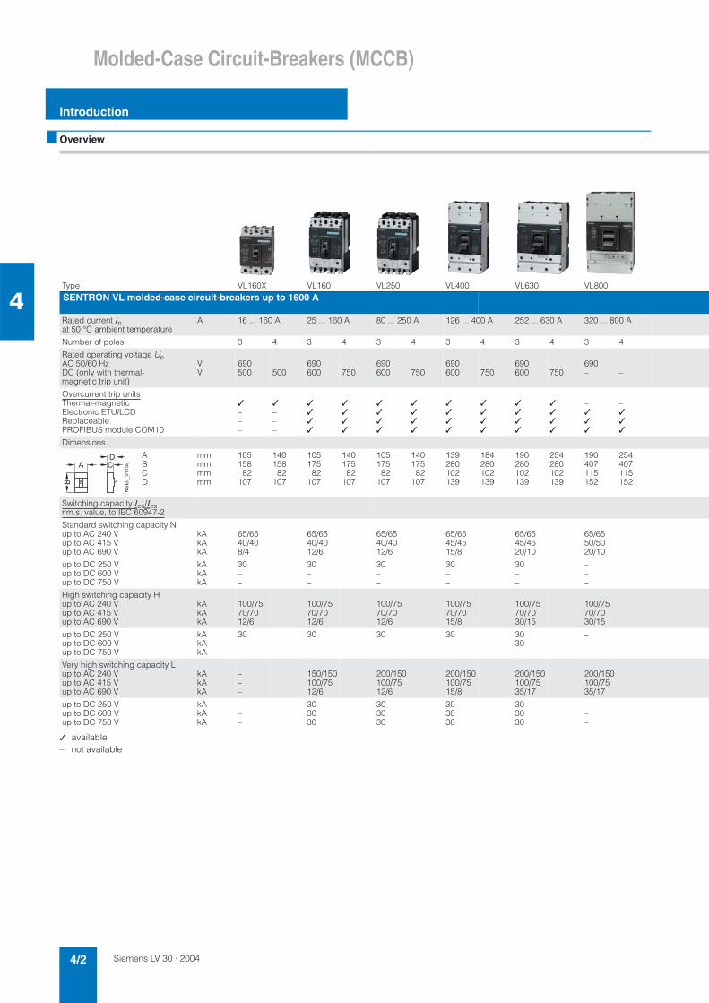
Type VL160X VL160 VL250 VL400 VL630 VL800SENTRON VL molded-case circuit-breakers up to 1600 A
Rated current Inat 50 °C ambient temperature
A 16 ... 160 A 25 ... 160 A 80 ... 250 A 126 ... 400 A 252 ... 630 A 320 ... 800 A
Number of poles 3 4 3 4 3 4 3 4 3 4 3 4
Rated operating voltage UeAC 50/60 Hz DC (only with thermal-magnetic trip unit)
VV
690500 500
690600 750
690600 750
690600 750
690600 750
690– –
Overcurrent trip unitsThermal-magneticElectronic ETU/LCDReplaceablePROFIBUS module COM10
✓–––
✓–––
✓✓✓✓
✓✓✓✓
✓✓✓✓
✓✓✓✓
✓✓✓✓
✓✓✓✓
✓✓✓✓
✓✓✓✓
–✓✓✓
–✓✓✓
Dimensions
ABCD
mmmmmmmm
10515882
107
14015882
107
10517582
107
14017582
107
10517582
107
140175
82107
139280102139
184280102139
190280102139
254280102139
190407115152
254407115152
Switching capacity Icu/Icsr.m.s. value, to IEC 60947-2
Standard switching capacity Nup to AC 240 Vup to AC 415 Vup to AC 690 V
kAkAkA
65/6540/408/4
65/6540/4012/6
65/6540/4012/6
65/6545/4515/8
65/6545/4520/10
65/6550/5020/10
up to DC 250 Vup to DC 600 Vup to DC 750 V
kAkAkA
30––
30––
30––
30––
30––
–––
High switching capacity Hup to AC 240 Vup to AC 415 Vup to AC 690 V
kAkAkA
100/7570/7012/6
100/7570/7012/6
100/7570/7012/6
100/7570/7015/8
100/7570/7030/15
100/7570/7030/15
up to DC 250 Vup to DC 600 Vup to DC 750 V
kAkAkA
30––
30––
30––
30––
3030–
–––
Very high switching capacity Lup to AC 240 Vup to AC 415 Vup to AC 690 V
kAkAkA
–––
150/150100/7512/6
200/150100/7512/6
200/150100/7515/8
200/150100/7535/17
200/150100/7535/17
up to DC 250 Vup to DC 600 Vup to DC 750 V
kAkAkA
–––
303030
303030
303030
303030
–––
����������
�
�
Siemens LV 30 · 2004 4/3
Molded-Case Circuit-Breakers (MCCB)
Introduction
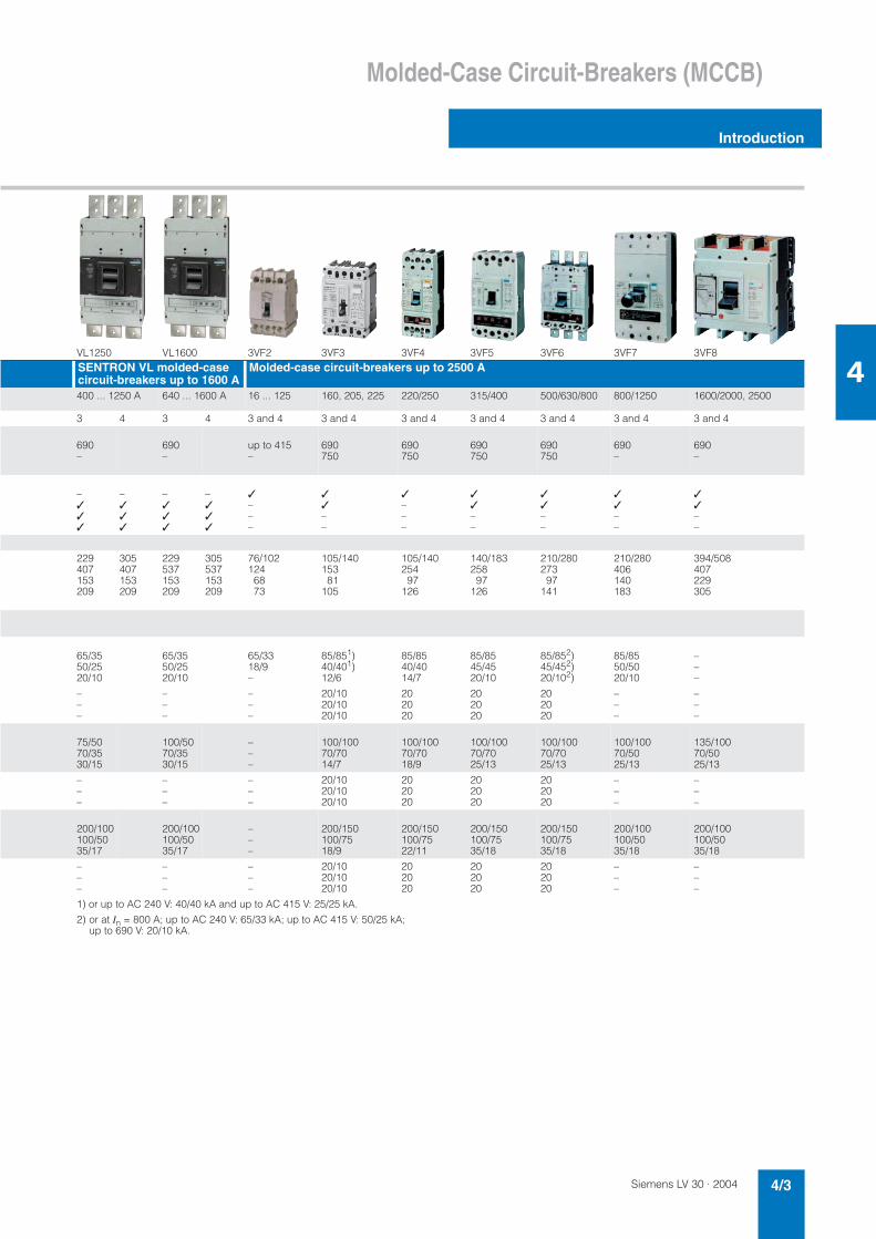
4VL1250 VL1600 3VF2 3VF3 3VF4 3VF5 3VF6 3VF7 3VF8SENTRON VL molded-case circuit-breakers up to 1600 A
Molded-case circuit-breakers up to 2500 A
400 ... 1250 A 640 ... 1600 A 16 ... 125 160, 205, 225 220/250 315/400 500/630/800 800/1250 1600/2000, 2500
3 4 3 4 3 and 4 3 and 4 3 and 4 3 and 4 3 and 4 3 and 4 3 and 4
690–
690–
up to 415–
690750
690750
690750
690750
690–
690–
–✓✓✓
–✓✓✓
–✓✓✓
–✓✓✓
✓–––
✓✓––
✓–––
✓✓––
✓✓––
✓✓––
✓✓––
229407153209
305407153209
229537153209
305537153209
76/1021246873
105/14015381
105
105/14025497
126
140/18325897
126
210/28027397
141
210/280406140183
394/508407229305
65/3550/2520/10
65/3550/2520/10
65/3318/9–
85/851)40/401)12/6
85/8540/4014/7
85/8545/4520/10
85/852)45/452)20/102)
85/8550/5020/10
–––
–––
–––
–––
20/1020/1020/10
202020
202020
202020
–––
–––
75/5070/3530/15
100/5070/3530/15
–––
100/10070/7014/7
100/10070/7018/9
100/10070/7025/13
100/10070/7025/13
100/10070/5025/13
135/10070/5025/13
–––
–––
–––
20/1020/1020/10
202020
202020
202020
–––
–––
200/100100/5035/17
200/100100/5035/17
–––
200/150100/7518/9
200/150100/7522/11
200/150100/7535/18
200/150100/7535/18
200/100100/5035/18
200/100100/5035/18
–––
–––
–––
20/1020/1020/10
202020
202020
202020
–––
–––
1) or up to AC 240 V: 40/40 kA and up to AC 415 V: 25/25 kA.
2) or at In = 800 A; up to AC 240 V: 65/33 kA; up to AC 415 V: 50/25 kA; up to 690 V: 20/10 kA.
Siemens LV 30 · 20044/4
SENTRON VL Circuit-Breakers up to 1600 A
General data
4
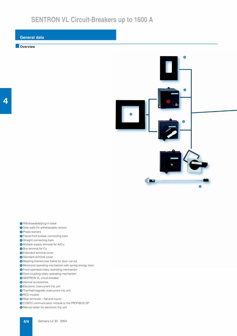
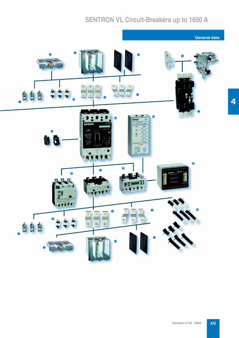
■ Overview
$Withdrawable/plug-in base
%Side walls for withdrawable version
&Phase barriers
(Flared front busbar connecting bars
)Straight connecting bars
*Multiple supply terminal for Al/Cu
+Box terminal for Cu
,Extended terminal cover
-Standard terminal cover
.Masking frame/cover frame for door cut-out
/Motorized operating mechanism with spring energy store
0Front-operated rotary operating mechanism
1Door-coupling rotary operating mechanism
2SENTRON VL circuit-breaker
3 Internal accessories
4Electronic overcurrent trip unit
5Thermal/magnetic overcurrent trip unit
6RCD module
7Rear terminals – flat and round
8COM10 communication module to the PROFIBUS DP
9Manual tester for electronic trip unit
.
0
/
1
.
Siemens LV 30 · 2004 4/5
SENTRON VL Circuit-Breakers up to 1600 A
General data
4
-
*
(
,%&
)
9
$
2
4
3
-
,
&
65
( 7
*
8
+
)
+
Siemens LV 30 · 20044/6
SENTRON VL Circuit-Breakers up to 1600 A
General data
4
■ Benefits
• The compact design of the SENTRON VL circuit-breakers cou-pled with excellent characteristics fulfills the high demands of today's electrical distribution systems.
• These circuit-breakers offer a broad product range, improved technology, space savings and easy operation.
• They are available both in thermal/magnetic (16 A to 630 A)and in electronic versions (63 A to 1600 A).
■ Area of application
The different versions of SENTRON VL circuit-breakers are suit-able for the following applications:• Incoming and outgoing circuit-breakers in distribution systems• Switching and protection devices for motors, transformers and
capacitors • Main control switches and EMERGENCY-STOP switches in
conjunction with lockable rotary operating mechanism and ter-minal covers.
The SENTRON VL circuit-breakers are available in the following versions:
1. For system protection (in 3 and 4-pole versions)The overload and short-circuit releases are designed for the pro-tection of cables, leads and non-motor loads.
2. For motor protection (in 3-pole versions) The overload and short-circuit releases are designed for opti-mized protection and direct starting of three-phase squirrel-cage motors. The circuit-breakers for motor protection are susceptible to phase failure and feature an adjustable trip class. The over-current trip units operate with a microprocessor.
3. For starter combinations (in 3-pole versions)These circuit-breakers are used both for short-circuit protection as well as for isolating functions, which may be required in starter combinations consisting of circuit-breakers, overload re-lays and motor contactors. These circuit-breakers exclusively feature adjustable, instantaneous short-circuit releases.
4. As non-automatic circuit-breakers (in 3- and 4-pole versions) These circuit-breakers can be used as feeder circuit-breakers, main control switches or disconnecting switches without over-load protection. They incorporate an integrated short-circuit self-protection system, eliminating the need for back-up fuses.
Standards and specifications
SENTRON VL circuit-breakers comply with:
IEC 60947-1, EN 60947-1, DIN VDE 0660, Part 100, IEC 60947-2, EN 60947-2, DIN VDE 0660, Part 101.Isolating features to IEC 60947-3, EN 60947-3.
Please contact Siemens for details of other standards.
The overcurrent trip units of the circuit-breakers for motor protec-tion also fulfill IEC 60947-4-1, DIN VDE 0660, Part 102.
Main control switches to EN 60204 or DIN VDE 0113 (see Area of application). EMERGENCY-STOP switches to EN 60204 or DIN VDE 0113 (see Area of application).
Operating conditions
The SENTRON VL circuit-breakers are climate-proof. They are intended for use in enclosed areas where no severe op-erating conditions (e.g. dust, corrosive vapors, damaging gases) are present.
When installed in dusty and damp areas, suitable enclosures must be provided.
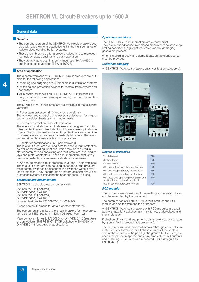
Utilization category
All SENTRON VL circuit-breakers satisfy utilization category A.
Degree of protection
RCD module
The RCD module is designed for retrofitting to the switch. It can also be retrofitted by the customer.
The combination of SENTRON VL circuit-breaker and RCD module can be fed from the top or bottom.
All SENTRON VL circuit-breakers with RCD modules are avail-able with auxiliary switches, alarm switches, undervoltage and shunt releases.
Protection of plant and equipment against overload or damage by ground faults (ground fault protection).
The RCD module trips the circuit-breaker through vectorial sum-mation current formation for all phase currents if the vectorial sum of the currents in the poles (= the ground fault current) ex-ceeds the pre-set response and delay time values. AC currents and pulsating DC currents are measured (CBR, design A to EN 60947-2).
Circuit-breaker IP20
Masking frame IP40
Terminal covers IP30
With front rotary operating mechanism IP40
With door-coupling rotary mechanism IP65
With motorized operating mechanism IP30
With motorized operating mechanism andmasking frame for the door cut-out
IP40
Plug-in base/withdrawable version IP20
Siemens LV 30 · 2004 4/7
SENTRON VL Circuit-Breakers up to 1600 A
General data
4
Switching of DC currents
The VL160X to VL630 circuit-breakers (for system protection with TM, for starter combinations, non-automatic circuit-breakers) can also be used for DC switching and protection applications.
The VL160 to VL1600 circuit-breakers with electronic trip units (ETU) are not suitable for DC applications.
However, the maximum permitted DC voltage for each current path needs to be taken into account for DC switching applica-tions.
For voltages above 250 V, a series connection of 2 or 3 current paths is required.
As the current has to flow through all of the current paths, the fol-lowing connections are recommended in order to satisfy the thermal tripping characteristics.
With DC applications, the response values of the instantaneous short-circuit releases ("I" trip units) are increased by 30 to 40%.
■ Design
• Rated current range from 16 A to 1600 A• Different switching capacity for each frame size
• No derating or loss of performance up to 50°C• Electronic overcurrent trip units from size 160 A (VL160), partic-
ularly for time-based discrimination and ground-fault protec-tion
• 2 families of internal accessories• Full range of external accessories e.g. terminals for aluminum
cable.
All circuit-breakers are supplied with integrated overcurrent trip units. The SENTRON VL160X to VL1600 circuit-breakers are avail-able with busbar connection pieces or box terminals (up to 400 A; see Page 4/10). Auxiliary switches/alarm switches or aux-iliary releases can be easily adapted by the customer, or they are also available ready installed if required. The switching capacity is shown on the front of every circuit-breaker.• Standard switching capacity:
Icu = 40 to 50 kA at AC 50/60 Hz 380/415 V• High switching capacity:
Icu = 70 kA at AC 50/60 Hz 380/415 V • Very high switching capacity:
Icu = 100 kA at AC 50/60 Hz 380/415 V
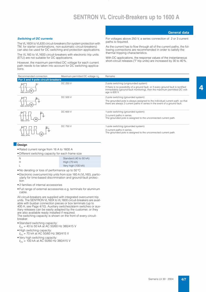
Recommended connection Maximum permitted DC voltage Ue RemarksFor 3 and 4-pole circuit-breakers
DC 250 V 2-pole switching (ungrounded system)
If there is no possibility of a ground fault, or if every ground fault is rectified immediately (ground-fault monitoring), then the maximum permitted DC volt-age is 600 V.
DC 500 V 2-pole switching (grounded system)
The grounded pole is always assigned to the individual current path, so that there are always 2 current paths in series in the event of a ground fault.
DC 600 V 1-pole switching (grounded system)
3 current paths in series. The grounded pole is assigned to the unconnected current path.
DC 750 V 1-pole switching (grounded system)
4 current paths in series. The grounded pole is assigned to the unconnected current path.
L
NSE0_00741M
L
L
NSE0_00742M
L
L
NSE0_00743M
L
L L
NSE0_00744M
N Standard (40 to 50 kA)H High (70 kA)L Very high (100 kA)
Siemens LV 30 · 20044/8
SENTRON VL Circuit-Breakers up to 1600 A
General data
4
Connection
The SENTRON VL160X to VL160 circuit-breakers are equipped with incoming and outgoing terminals which are suitable for stranded conductors, flexible copper rails and conductors with end sleeves. Different supply terminals are available for VL630 to VL1600 (sizes 630 A to 1600 A).
Appropriate accessories for screw connection to fixed and flex-ible copper bars or cables are available for SENTRON VL160X to VL1600 circuit-breakers.
SENTRON VL160X to VL1600 circuit-breakers can be equipped with connecting bars. These are intended for connection of stan-dard busbars and can be used for front or rear connection. The SENTRON VL1600 circuit-breaker is supplied with front con-necting bars.
The incoming and outgoing connections for the circuit-breaker can be freely selected. The electrical specifications remain the same.The infeed for circuit-breakers with RCD modules can be con-nected above or below.
Bare conductors at the top connections must be insulated in the arc quenching space that is necessary above the arcing cham-bers. Phase barriers or terminal covers can be used for this pur-pose.
For the SENTRON VL160X to VL1600 circuit-breakers, the con-nections for the internal accessories (auxiliary releases, auxiliary switches and alarm switches) are supplied with terminal screws.
The auxiliary releases (shunt releases and undervoltage re-leases), auxiliary switches and alarm switches for all SENTRON VL circuit-breakers can be connected easily and directly.
The motorized operating mechanisms with spring energy stores are always equipped with terminals. The leading auxiliary switches for the rotary operating mechanisms are always sup-plied with connecting leads.
SENTRON VL160X circuit-breakers
The main components of the SENTRON VL160X circuit-breakers are the three conducting paths with the incoming and outgoing terminals. The fixed and moving contacts are designed in such a way that the contacts are magnetically repelled if there is a short-circuit. In conjunction with the arcing chambers, a dy-namic impedance is created that causes current limiting due to a reduction in the damaging effects of I2t and Ip energy that arises during short-circuits.
The trip unit is preassembled and equipped with fixed or adjust-able overload releases as well as with fixed short-circuit releases for each pole.
The circuit-breaker is trip-free.
To the right and left of the operating mechanism, the double-in-sulated accessory compartments are situated for the auxiliary releases and auxiliary switches.
SENTRON VL160 to VL630 circuit-breakers
The arrangement of the current path, main contact and switch-ing mechanism corresponds to that of the SENTRON VL160X circuit-breakers. The trip units for the SENTRON VL160 to VL630 have the follow-ing features:• The trip units are available in thermal-magnetic and electronic
versions. They can be replaced by the customer using a spe-cial tool.
• The thermal-magnetic trip units have adjustable overload and short-circuit releases.
SENTRON VL800 to VL1600 circuit-breakers
The arrangement of the current paths and switching mecha-nisms corresponds with those of the SENTRON VL160X to VL630 circuit-breakers.
The SENTRON VL800 to VL1600 circuit-breakers are only avail-able with electronic trip units.
As is the case for all versions of the SENTRON VL circuit-break-ers with electronic trip units, the current transformers are in the same enclosure as the trip units. They send a signal which is proportional to the load current to the electronic overcurrent trip-ping unit.
All SENTRON VL circuit-breakers with electronic trip units mea-sure the actual r.m.s. current. This type of measurement is the most accurate method. Currents in today's electrical distribution systems with many harmonics are evaluated reliably.
Overcurrent trip unit systems
1. Overcurrent trip unit system of the SENTRON VL160X to VL630 circuit-breakers - thermal-magnetic
The overcurrent and short-circuit releases function with bimetal-lic and magnetic trip units. They are available in fixed set or ad-justable versions.
The four-pole circuit-breakers for system protection can be equipped with overcurrent trip units for all four poles or without an overcurrent trip unit for the fourth pole (N). From 100 A and higher, the trip units for the fourth pole (N) are set to 60% of the current for the 3 main current paths, so that safe protection for neutral conductors with a reduced cross-section is ensured.
The circuit-breakers for starter combination applications are usually combined with a motor contactor and a suitable overload relay.
The non-automatic circuit-breakers have an integrated short-circuit self-protection system eliminating the need for back-up fuses. These circuit-breakers have no overload protection. Four-pole circuit-breakers do not have a short-circuit release for the fourth pole (N).
2. Overcurrent trip unit system for SENTRON VL160 to VL1600 circuit-breakers, electronic, ETU
The electronic overcurrent trip unit system consists of:• 3 current transformers• Evaluation electronics with microprocessor• Tripping solenoid.
For SENTRON VL160 and VL250, the tripping solenoid is in-stalled in the left accessory compartment.
An auxiliary power supply is not necessary for the release.
A minimum load current of approx. 20 % of the corresponding rated current In of the circuit-breaker is required to activate the microprocessor trip units.
At the output of the electronic overcurrent trip unit module there is a tripping solenoid which trips in the case of overload or short-circuit.
Abbreviations (functions)
L, S, I, G designations in accordance with IEC 60947
L = Long Time Delay = Overload protection
S = Short Time Delay = Short-circuit protection (short-time delayed)
I = Instantaneous = Short-circuit protection(instantaneous)
G = Ground Fault = Ground-fault protection
Siemens LV 30 · 2004 4/9
SENTRON VL Circuit-Breakers up to 1600 A
General data
4
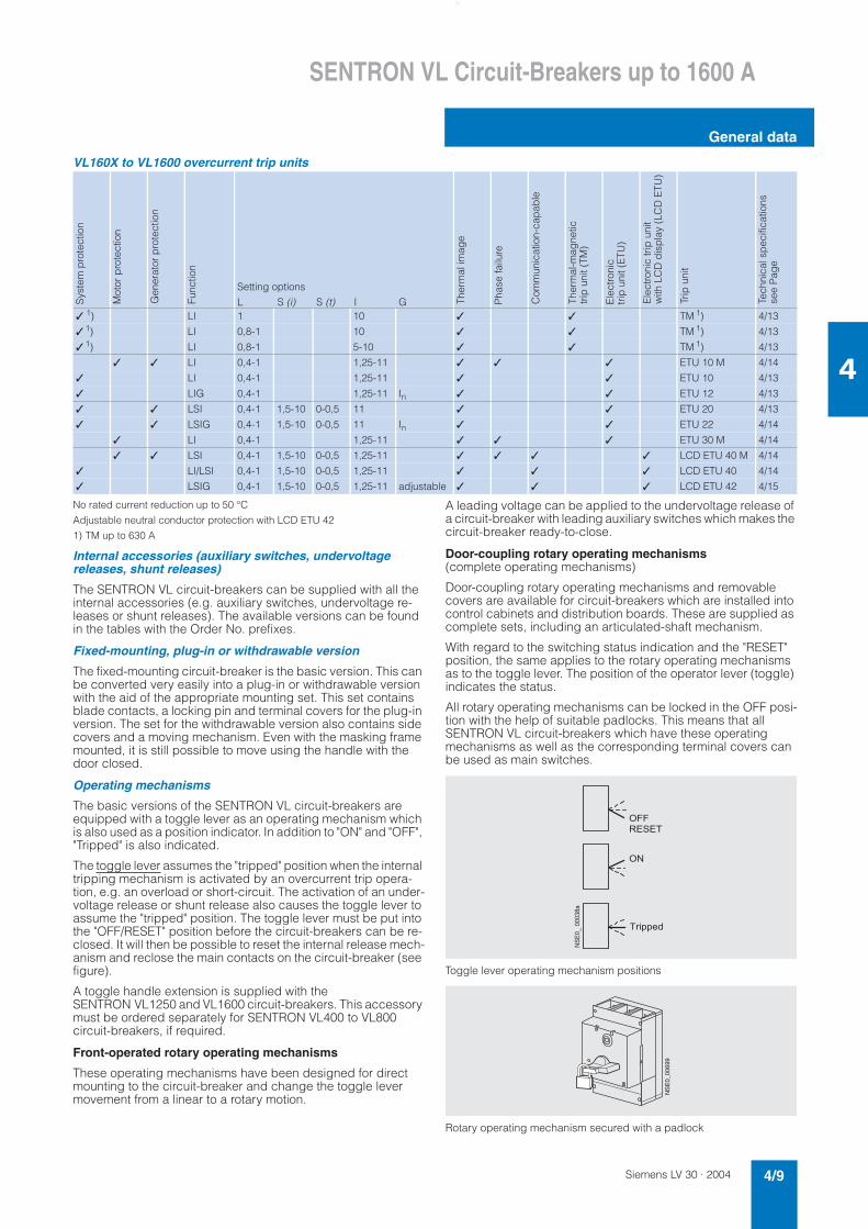
VL160X to VL1600 overcurrent trip units
No rated current reduction up to 50 °C
Adjustable neutral conductor protection with LCD ETU 42
1) TM up to 630 A
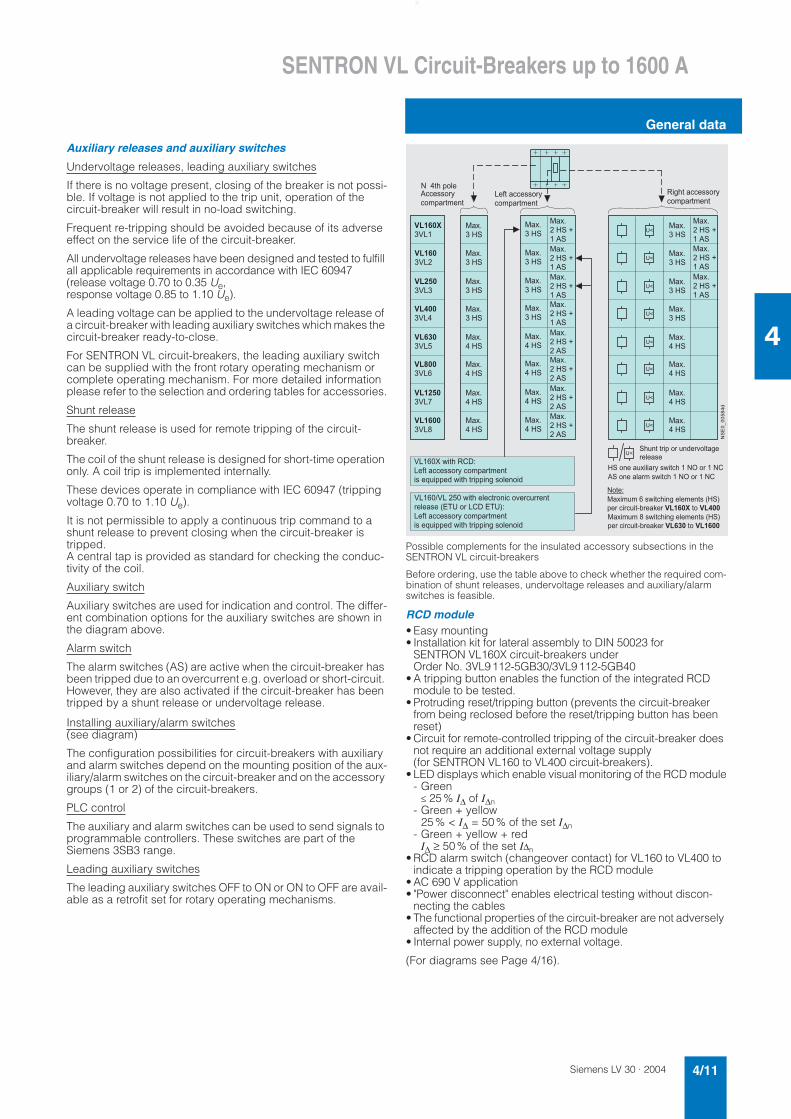
Internal accessories (auxiliary switches, undervoltage releases, shunt releases)
The SENTRON VL circuit-breakers can be supplied with all the internal accessories (e.g. auxiliary switches, undervoltage re-leases or shunt releases). The available versions can be found in the tables with the Order No. prefixes.
Fixed-mounting, plug-in or withdrawable version
The fixed-mounting circuit-breaker is the basic version. This can be converted very easily into a plug-in or withdrawable version with the aid of the appropriate mounting set. This set contains blade contacts, a locking pin and terminal covers for the plug-in version. The set for the withdrawable version also contains side covers and a moving mechanism. Even with the masking frame mounted, it is still possible to move using the handle with the door closed.
Operating mechanisms
The basic versions of the SENTRON VL circuit-breakers are equipped with a toggle lever as an operating mechanism which is also used as a position indicator. In addition to "ON" and "OFF", "Tripped" is also indicated.
The toggle lever assumes the "tripped" position when the internal tripping mechanism is activated by an overcurrent trip opera-tion, e.g. an overload or short-circuit. The activation of an under-voltage release or shunt release also causes the toggle lever to assume the "tripped" position. The toggle lever must be put into the "OFF/RESET" position before the circuit-breakers can be re-closed. It will then be possible to reset the internal release mech-anism and reclose the main contacts on the circuit-breaker (see figure).
A toggle handle extension is supplied with the SENTRON VL1250 and VL1600 circuit-breakers. This accessory must be ordered separately for SENTRON VL400 to VL800 circuit-breakers, if required.
Front-operated rotary operating mechanisms
These operating mechanisms have been designed for direct mounting to the circuit-breaker and change the toggle lever movement from a linear to a rotary motion.
A leading voltage can be applied to the undervoltage release of a circuit-breaker with leading auxiliary switches which makes the circuit-breaker ready-to-close.
Door-coupling rotary operating mechanisms(complete operating mechanisms)
Door-coupling rotary operating mechanisms and removable covers are available for circuit-breakers which are installed into control cabinets and distribution boards. These are supplied as complete sets, including an articulated-shaft mechanism.
With regard to the switching status indication and the "RESET" position, the same applies to the rotary operating mechanisms as to the toggle lever. The position of the operator lever (toggle) indicates the status.
All rotary operating mechanisms can be locked in the OFF posi-tion with the help of suitable padlocks. This means that all SENTRON VL circuit-breakers which have these operating mechanisms as well as the corresponding terminal covers can be used as main switches.
Toggle lever operating mechanism positions
Rotary operating mechanism secured with a padlock
Setting options
L S (i) S (t) I G✓ 1) LI 1 10 ✓ ✓ TM 1) 4/13
✓ 1) LI 0,8-1 10 ✓ ✓ TM 1) 4/13
✓ 1) LI 0,8-1 5-10 ✓ ✓ TM 1) 4/13
✓ ✓ LI 0,4-1 1,25-11 ✓ ✓ ✓ ETU 10 M 4/14
✓ LI 0,4-1 1,25-11 ✓ ✓ ETU 10 4/13
✓ LIG 0,4-1 1,25-11 In ✓ ✓ ETU 12 4/13
✓ ✓ LSI 0,4-1 1,5-10 0-0,5 11 ✓ ✓ ETU 20 4/13
✓ ✓ LSIG 0,4-1 1,5-10 0-0,5 11 In ✓ ✓ ETU 22 4/14
✓ LI 0,4-1 1,25-11 ✓ ✓ ✓ ETU 30 M 4/14
✓ ✓ LSI 0,4-1 1,5-10 0-0,5 1,25-11 ✓ ✓ ✓ ✓ LCD ETU 40 M 4/14
✓ LI/LSI 0,4-1 1,5-10 0-0,5 1,25-11 ✓ ✓ ✓ LCD ETU 40 4/14
✓ LSIG 0,4-1 1,5-10 0-0,5 1,25-11 adjustable ✓ ✓ ✓ LCD ETU 42 4/15
Sys
tem
pro
tect
ion
Mot
or p
rote
ctio
n
Gen
erat
or p
rote
ctio
n
Func
tion
Ther
mal
imag
e
Pha
se fa
ilure
Com
mun
icat
ion-
cap
able
Ther
mal
-mag
netic
tr
ip u
nit (
TM)
Ele
ctro
nic
trip
uni
t (E
TU)
Ele
ctro
nic
trip
uni
tw
ith L
CD
dis
pla
y (L
CD
ETU
)
Trip
uni
t
Tech
nica
l sp
ecifi
catio
ns
see
Pag
e
�����������
������
�
������
�����
����
�
Siemens LV 30 · 20044/10
SENTRON VL Circuit-Breakers up to 1600 A
General data
4
Motorized operating mechanism with spring energy store
The SENTRON VL160X to VL1600 circuit-breakers (sizes 160 to 1600 A) can be equipped with motorized operating mechanisms for remote opening and closing during operation.
These motorized operating mechanisms with spring energy stores for SENTRON VL160X to VL800 circuit-breakers have a stored-energy feature (for synchronization) with a maximum ON period of tE ≤ 100 ms. The SENTRON VL1250 and VL1600 cir-cuit-breakers are motor driven (tE ≤ 5 s). In addition, they permit remote opening of the circuit-breaker. The motorized operating mechanisms with spring energy store are always supplied with
a locking device for padlocks. Optional safety locks are also available.
These devices can be used to block the operating mechanism electrically and mechanically. All remote-controlled mechanisms are equipped with a manual operation option for maintenance purposes.
Main connections, basic equipment and options
- = scope of supply
x = available
– = not available
SENTRON VL160X and VL160 circuit-breakers
SENTRON VL250 to VL1250 circuit-breakers
SENTRON VL1600 circuit-breakers
Box terminal for copper cables or busbars
Connection with screw connection (available with direct cable lug connec-tion on VL160X, VL160, VL250, VL400)
Connection to front busbar connecting bars
For conductor cross-sections see Page 4/17
����������
����������
����������
Main connections
Circuit-breakers Connection overview and further options
Box terminals Connection with screw connection with metric thread
Circular conductor terminal (for Al/Cu cables)
Rear-mountingterminals
Front-accessible connecting bars
VL160X o x x x x
VL160 o x x x x
VL250 x o x x x
VL400 x o x x x
VL630 – o x x x
VL800 – o x x x
VL1250 – o x x x
VL1600 – x – x o
Siemens LV 30 · 2004 4/11
SENTRON VL Circuit-Breakers up to 1600 A
General data
4
Auxiliary releases and auxiliary switches
Undervoltage releases, leading auxiliary switches
If there is no voltage present, closing of the breaker is not possi-ble. If voltage is not applied to the trip unit, operation of the circuit-breaker will result in no-load switching.
Frequent re-tripping should be avoided because of its adverse effect on the service life of the circuit-breaker.
All undervoltage releases have been designed and tested to fulfill all applicable requirements in accordance with IEC 60947 (release voltage 0.70 to 0.35 Ue,response voltage 0.85 to 1.10 Ue).
A leading voltage can be applied to the undervoltage release of a circuit-breaker with leading auxiliary switches which makes the circuit-breaker ready-to-close.
For SENTRON VL circuit-breakers, the leading auxiliary switch can be supplied with the front rotary operating mechanism or complete operating mechanism. For more detailed information please refer to the selection and ordering tables for accessories.
Shunt release
The shunt release is used for remote tripping of the circuit-breaker.
The coil of the shunt release is designed for short-time operation only. A coil trip is implemented internally.
These devices operate in compliance with IEC 60947 (tripping voltage 0.70 to 1.10 Ue).
It is not permissible to apply a continuous trip command to a shunt release to prevent closing when the circuit-breaker is tripped.A central tap is provided as standard for checking the conduc-tivity of the coil.
Auxiliary switch
Auxiliary switches are used for indication and control. The differ-ent combination options for the auxiliary switches are shown in the diagram above.
Alarm switch
The alarm switches (AS) are active when the circuit-breaker has been tripped due to an overcurrent e.g. overload or short-circuit. However, they are also activated if the circuit-breaker has been tripped by a shunt release or undervoltage release.
Installing auxiliary/alarm switches(see diagram)
The configuration possibilities for circuit-breakers with auxiliary and alarm switches depend on the mounting position of the aux-iliary/alarm switches on the circuit-breaker and on the accessory groups (1 or 2) of the circuit-breakers.
PLC control
The auxiliary and alarm switches can be used to send signals to programmable controllers. These switches are part of theSiemens 3SB3 range.
Leading auxiliary switches
The leading auxiliary switches OFF to ON or ON to OFF are avail-able as a retrofit set for rotary operating mechanisms.
Possible complements for the insulated accessory subsections in the SENTRON VL circuit-breakers
Before ordering, use the table above to check whether the required com-bination of shunt releases, undervoltage releases and auxiliary/alarm switches is feasible.
RCD module• Easy mounting • Installation kit for lateral assembly to DIN 50023 for
SENTRON VL160X circuit-breakers under Order No. 3VL9112-5GB30/3VL9112-5GB40
• A tripping button enables the function of the integrated RCD module to be tested.
• Protruding reset/tripping button (prevents the circuit-breaker from being reclosed before the reset/tripping button has been reset)
• Circuit for remote-controlled tripping of the circuit-breaker does not require an additional external voltage supply (for SENTRON VL160 to VL400 circuit-breakers).
• LED displays which enable visual monitoring of the RCD module- Green
≤ 25% I∆ of I∆n- Green + yellow
25% < I∆ = 50% of the set I∆n- Green + yellow + red
I∆ ≥ 50% of the set I∆n• RCD alarm switch (changeover contact) for VL160 to VL400 to
indicate a tripping operation by the RCD module• AC 690 V application • "Power disconnect" enables electrical testing without discon-
necting the cables• The functional properties of the circuit-breaker are not adversely
affected by the addition of the RCD module • Internal power supply, no external voltage.
(For diagrams see Page 4/16).
�����������
������������
�������
�������
���������
���������
��������
��������
���������
���������
����������
��������!��"�
��������!��"�
�������
�������
�������
�������
�������
�������
�������
�������
�������
��������!��"�
�������
��������!��"�
�������
��������!��"�
�������
��������!��"�
�������
��������!��"�
�������
��������!��"�
�������
��������!��"�
���������
��������!��"�
���������
��������!��"�
���������
���������
���������
���������
���������
��
����#$��%&���'#�((�))%�*(%+��#+�,#
�����-�.�#$��/01��'#�((�))%�*�(%+��#+�,#�)��23������.�#$�#�����,4�)%&�,%��
�����5�������.�#$��&�(#�%,�(�%6��(3���,#��&�)��7� ��%���/0�� �81������'#�((�))%�*�(%+��#+�,#�)��23������.�#$�#�����,4�)%&�,%��
�$3,#�#����%��3,���6%���&�)�
�������%,��3��&��*�).�#($�����%�����/����"��%,��&�+�).�#($�����%�����/
�%#�1���+3+���).�#($�,4��&�+�,#)�7��8����(��(3�#9:��;����������#%��������+3+���).�#($�,4��&�+�,#)�7��8����(��(3�#9:��;��������#%�������
��4$#�((�))%�*(%+��#+�,#
"((�))%�*(%+��#+�,#
Siemens LV 30 · 20044/12
SENTRON VL Circuit-Breakers up to 1600 A
General data
4
■ Functions
Current limitation
The SENTRON VL circuit-breakers utilize the design principle of magnetic repulsion of the contacts. The contacts open before the anticipated peak value of the short-circuit current is achieved. The current-limiting effects of the SENTRON VL circuit-breakers provide effective protection for system compo-nents against the thermal and dynamic effects of the short-circuit current in the event of an electrical fault.
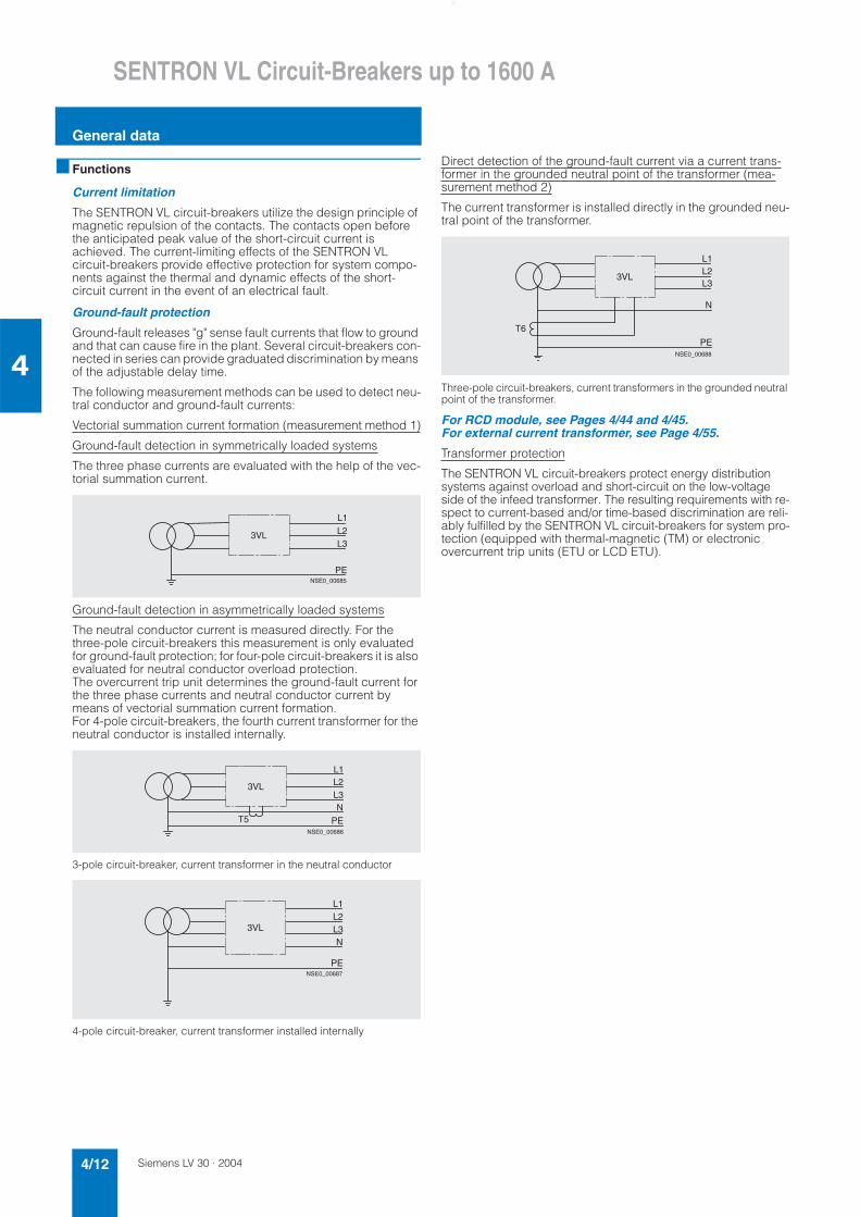
Ground-fault protection
Ground-fault releases "g" sense fault currents that flow to ground and that can cause fire in the plant. Several circuit-breakers con-nected in series can provide graduated discrimination by means of the adjustable delay time.
The following measurement methods can be used to detect neu-tral conductor and ground-fault currents:
Vectorial summation current formation (measurement method 1)
Ground-fault detection in symmetrically loaded systems
The three phase currents are evaluated with the help of the vec-torial summation current.
Ground-fault detection in asymmetrically loaded systems
The neutral conductor current is measured directly. For the three-pole circuit-breakers this measurement is only evaluated for ground-fault protection; for four-pole circuit-breakers it is also evaluated for neutral conductor overload protection. The overcurrent trip unit determines the ground-fault current for the three phase currents and neutral conductor current by means of vectorial summation current formation. For 4-pole circuit-breakers, the fourth current transformer for the neutral conductor is installed internally.
3-pole circuit-breaker, current transformer in the neutral conductor
4-pole circuit-breaker, current transformer installed internally
Direct detection of the ground-fault current via a current trans-former in the grounded neutral point of the transformer (mea-surement method 2)
The current transformer is installed directly in the grounded neu-tral point of the transformer.
Three-pole circuit-breakers, current transformers in the grounded neutral point of the transformer.
For RCD module, see Pages 4/44 and 4/45. For external current transformer, see Page 4/55.
Transformer protection
The SENTRON VL circuit-breakers protect energy distribution systems against overload and short-circuit on the low-voltage side of the infeed transformer. The resulting requirements with re-spect to current-based and/or time-based discrimination are reli-ably fulfilled by the SENTRON VL circuit-breakers for system pro-tection (equipped with thermal-magnetic (TM) or electronic overcurrent trip units (ETU or LCD ETU).
L1L2L3
PE
3VL
NSE0_00685
L1L2L3N
PE
3VL
T5NSE0_00686
L1L2L3N
PE
3VL
NSE0_00687
L1L2L3
3VL
T6
PE
N
NSE0_00688
Siemens LV 30 · 2004 4/13
SENTRON VL Circuit-Breakers up to 1600 A
General data
4
Thermal-magnetic overcurrent trip unit
Electronic overcurrent trip units ETU
1) Depending on size, see Page 4/23 (3-pole) and Page 4/30 (4-pole)
Application: system protection – TM, LI/LIN function
Overload protection (fixed), short-circuit protection (fixed); see selection table for VL160X (trip units installed in the switch enclosure)
Application: system protection – TM, LI/LIN function
Overload protection (adjustable IR = 0.8 to 1 × In),short-circuit protection (fixed); see selection tables for VL160X (trip units installed in the switch enclosure)
Application: system protection – TM, LI/LIN function
Overload protection (adjustable IR = 0.8 to 1 × In),short-circuit protection (adjustable Ii = 5 to 10 × In, for VL160 to VL630)
L
I
NSE0_00689
2 4 6
63AOFF
CAT.A50° CTM ~=
NSE-00539
L
I
NSE0_00690
�1.0 .8
R�nx
63AOFF
CAT.A50° CTM ~=
2 4 6
NSE-00540
L
I
NSE0_00691
2
5
6
7
nx
10
9
8
i
4 6
TM
50 C
CAT.A
=160An
x n.8
DCR 1.0
16�
� �~=
NSE-00541
�
� iR
�
�
For types VL160 to VL1600
General
No auxiliary voltage for tripping unit required
All ETUs have a thermal image
Flashing green LED indicates faultless operation of microprocessor
Overload status (I > 1.05 × IR) is indicated by continuous yellow LED (alarm)
Integrated self-test function
Female connector for test unit
Application: system protection – ETU10, LI/LIN function
Overload protection IR = 0.4; 0.45; 0.5 to 0.95; 1 × In, time-lag class tR = 2.5 to 30
Short-circuit protection (instantaneous) Ii = 1.25 to 11 × In
1)
Application: system and generator protection – ETU20, LSI/LSIN function
Overload protection IR = 0.4; 0.45; 0.5 to 0.95; 1 × In,
Short-circuit protection (short-time delayed) Isd = 1.5 to 10 × IR, tsd = 0 to 0.5 s,
I2t selectable on/off
Short-circuit protection (instantaneous) Ii = 11 × In (fixed)1)
Application: system protection – ETU12, LIG/LING function
Overload protection IR = 0.4; 0.45; 0.5 to 0.95; 1 × In, time-lag class tR = 2.5 to 30
Short-circuit protection (instantaneous) I = 1.25 to 11 × In
1)
Ground-fault protection:Measurement method no. 1: (GR) vectorial summation current formation for the currents of the three phases/and neutral conductor (four-conductor systems); I∆n = In, versions "AC", "AD", "BC", "BD" (for Order No. supplements see Page 4/25 or 4/31)
Measurement method no. 2: (GGND) direct detection of ground-fault current via current transformer installed in grounded neutral point, Ig = In (instantaneous); version "AJ" (for Order No. supplements see Page 4/25)
L
I
NSE0_00691
CAT.A =250A ~� n 25 AB
nx �
R�Alarm
X3
>1.05
25 AB
.45
.6
.9
1.0.95
.7.8
.4
.63
30
14
Rt 20.5
(S)Rt
25
R� i�
17
8
� i
nx �
6
2.54
108
2
1.251.5
43
1011
56
Active
NSE0_00542
L
SI
NSE0_00920
Alarm
>1.05
CAT.A
25 AEX3
.45
=250A
.6
1.0�R
.95
.9
.4
n�
n�x.7 .63
.8
108
�sd
sdt 7.5
~
sdR�� 56
.2
(S)
t22
tsd
�1.5
ONx�
2.5
4 3 R
0OFF
t2�.1
.2
.4
Active
.3
.3.4
.5.1
25 AE
NSE-00543
L
IG
NSE0_00693
.95
CAT.A
X3
>1.05
25 AD
R
x n
.8
.9
Alarm (S)t1.0 2.530.4
.5
.45
.7 .63
R
iR
Rt
101417
25
2086
4
i 1.2511
Active5
x n
6
8
10
4
2
3
1.5
=250An ~ 25 ADn n=
NSE-00544
Siemens LV 30 · 20044/14
SENTRON VL Circuit-Breakers up to 1600 A
General data
4
Electronic overcurrent trip units LCD ETU
1) Depending on size, see Page 4/23 (3-pole) and Page 4/30 (4-pole)
Application: system and generator protection – ETU22, LSIG/LSING function
Overload protection IR = 0.4; 0.45; 0.5 to 0.95; 1 × In,
Short-circuit protection (short-time delayed) Isd = 1.5 to 10 × IR, tsd = 0 to 0.5 s,
I2t selectable on/off
Short-circuit protection (instantaneous) Ii = 11 × In(fixed)1)
Ground-fault protection:Measurement method no. 1: (GR) vectorial summation current formation for the currents of the three phases/and neutral conductor (4-conductor systems); I∆n = In, versions "AG", "AH", "BG", "BH" (for Order No. supplements see Page 4/25 or 4/31)
Measurement method no. 2: (GGND) direct detection of ground-fault current via current transformer, Ig = In (instantaneous); version "AK" (for Order No. supplements see Page 4/25)
Application: motor protection – ETU10M, LI function
Overload protection adjustable in small steps IR = 0.41; 0.42 to 0.98; 0.99; 1 × In,trip class tc = 10 (fixed)
Thermal image
Short-circuit protection (instantaneous) Ii = 1.25 to 11 × In
1)with phase failure sensitivity
Application: motor protection – ETU30M, LI function
Overload protection adjustable in small steps IR = 0.41; 0.42 to 0.98; 0.99; 1 × In,trip class tc = 10 A, 10, 20, 30
Thermal image
Short-circuit protection (instantaneous) Ii = 6 to 11 × In with phase failure sensitivity
NSE0_00921
L
SIG
sd
.95
25 AG
CAT.A
X3
.9
�x n
.8
Alarm
>1.05R� sd
.5
.63.7.6 sdt
R� �sd
.45.41.0
�
4
7
65
�x2.5
R3
1.58
10t
2 OFF
Active
� t
.5
ON.2
.1
.2
.4.3
.4(S)
2 .3 .10 �2t
= 250An� ~ 25 AGn
NSE-00545
n� = �
NSE0_00943
L
I
Alarm
25 AP
CAT.A
>1.05
X3
�.100.4
0.70.80.9
+
x�
0.60.5
R
n
.07.06
.08
.09
IEC 60947-4EN 60947-4i�
11.01 1.2510
.04.05
.03
.02
6R� i�
8
3
1.5
5 4
Active
�nx2
=250An� ~ 25 AP
NSE-00546
L
I
NSE0_00691 nx
Alarm
>1.050.4
i =11x
NSE0_01160
X3
0.50.6
0.70.80.9
R .10 .01.02.03
.04.05.06
.07
.08.09
TC i=6x n
Active
i=8x n
1020
30 102030
102030
10A
n25 AS
General
No auxiliary voltage for trip unit required
Current indicator
Illuminated LCD display indicates faultlessoperation of microprocessor
Overload status (I > 105% IR) is indicated by "overload" on the LCD display
User-friendly, menu-driven settingof protection parameters in absolute ampere values via keys
Integrated self-test function
Female connector for test/programming device
For communication link to PROFIBUS DP see Section 3 "Communication-capable circuit-breakers".
Application: system protection – ETU40, LSI functions and motor protection – ETU40M, LSI/LSIN function
Overload protection IR = 0.4 to 1 × In,trip class tc = 2.5 to 30
On/off selectable thermal image
Short-circuit protection (short-time delayed) Isd = 1.5 to 10 × IR, tsd = 0 to 0.5 s,
I2t selectable on/off
Short-circuit protection (instantaneous) Ii = 1.25 to 11 × In
1)
NSE0_00944
L
I
ESCL1=178; L2=181
L3=179; N=0
CAT.A =250An� ~ 25 CLn n� = �
NSE-00547
Siemens LV 30 · 2004 4/15
SENTRON VL Circuit-Breakers up to 1600 A
General data
4
1) Depending on size, see Page 4/23 (3-pole) and Page 4/30 (4-pole)
■ Integration
Mounting
The SENTRON VL circuit-breakers are suitable for use in open and enclosed switchboards and distribution systems. The rec-ommended mounting positions for the SENTRON VL circuit-breakers are shown in the diagrams under "Technical specifica-tions, permissible mounting positions".
Application: system protection – ETU42, LSIG/LSING function
Overload protection IR = 0.4 to 1 x In,time-lag class tR = 2.5 to 30
On/off selectable thermal image
Short-circuit protection (short-time delayed) Isd = 1.5 to 10 × IR, tsd = 0 to 0.5 s,
I2t selectable on/off
Short-circuit protection (instantaneous) Ii = 1.25 to 11 × In
1)
Ground-fault protection:Measurement method 1: (GR) vectorial summation current formation for the currents of the three phases/and neutral conductor (4-conductor systems); I∆n = 0.4 to 1 × In, versions "CL", "CM", "CN" (for Order No. supplements see Page 4/26 or 4/32)
Measurement method 2: (GGND) direct detection of ground-fault current via current transformer, Ig = 0.4 to 1 × In,tg = 0.1 to 0.5 s; version "CM" (for Order No. supplements see Page 4/26)
L
S
IG
NSE0_00697
ESCL1=178; L2=181
L3=179; N=0
CAT.A =250An� ~ 25 CLn n� = �
NSE-00547

Siemens LV 30 · 20044/16
SENTRON VL Circuit-Breakers up to 1600 A
General data
4
■ Technical specifications
1) Circuit-breaker cannot be used for direct current.
Type VL160X3VL1
VL1603VL2
VL2503VL3
VL4003VL4
VL6303VL5
VL8003VL6
VL12503VL7
VL16003VL8
Max. rated current Independing on the version
A 160 160 250 400 630 800 1250 1600
Rated insulation voltage Ui to IEC 60947-2Main circuits AC V 800 800 800 800 800 800 800 800Auxiliary circuits AC V 690 690 690 690 690 690 690 690
Rated impulse withstand voltage UimpMain circuits kV 8 8 8 8 8 8 8 8Auxiliary circuits kV 4 4 4 4 4 4 4 4
Rated operating voltage Ue, 50/60 HzIEC AC V 690 690 690 690 690 690 690 690NEMA AC V 600 600 600 600 600 600 600 600
Permissible ambient temperature °C –25 ... +70 –25 ... +70 –25 ... +70 –25 ... +70 –25 ... +70 –25 ... +70 –25 ... +70 –25 ... +70
Permissible load at various ambient temperaturesclose to the circuit-breaker, related to therated current of the circuit-breaker
• Circuit-breakers for system protec-tion
at 40 °C % 100 100 100 100 100 100 100 100
at 50 °C % 100 100 100 100 100 100 100 100
at 60 °C % 93 93 93 93 93 95 95 95
at 70 °C % 86 86 86 86 86 86 86 80
• Circuit-breakers for motor protection at 40 °C % – 100 100 100 100 – – –
at 50 °C % – 100 100 100 100 – – –
at 60 °C % – 93 93 93 93 – – –
at 70 °C % – 86 86 86 86 – – –
• Circuit-breakers for starter combinations and non-automaticcircuit-breakers
at 40 °C % 100 100 100 100 100 100 100 100
at 50 °C % 100 100 100 100 100 100 100 100
at 60 °C % 93 93 93 93 93 95 95 95
at 70 °C % 86 86 86 86 86 86 86 80
Rated short-circuit switching capacity (DC)
for SENTRON VL circuit-breakers with TM trip unitTime constant t = 15 ms
1 current path
up to DC 250 V
2 current paths in seriesDC 440 V
3 current paths in series DC 600 V
kA 30 30 30 30 30 –1) –1) –1)
NEMATime constant t = 8 ms
1 current path 2 current pathsin series
DC 250 V–
–DC 250 V
kAkA
3030
3030
3030
3030
3030
–1)–1)
–1)–1)
–1)–1)
Weights of 3-pole circuit-breakersBasic unit without overcurrent trip unit Thermal-magnetic overcurrent trip unit Electronic overcurrent trip unit Basic unit
with thermal-magnetic overcurrent trip unitwith electronic overcurrent trip unit
kgkgkg
kgkg
–––
2.0–
1.50.70.9
2.22.4
1.60.70.9
2.32.5
4.21.51.7
5.75.9
7.81.21.5
9.09.3
14.2–1.8
–16.0
21–4.0
–25.0
27.3–4.0
–31.3
Weights of 4-pole circuit-breakers Basic unit without overcurrent trip unit Thermal-magnetic overcurrent trip unit Electronic overcurrent trip unit Basic unit
with thermal-magnetic overcurrent trip unit with electronic overcurrent trip unit
kgkgkg
kgkg
–––
2.5–
2.01.01.1
3.03.1
2.21.01.1
3.23.3
5.51.92.1
7.47.6
9.71.52.0
11.211.7
18.2–2.3
–20.5
27.5–6.0
–33.5
34.8–6.0
–40.8
Rated short-circuit switching capacity to IEC 60947-2 (at 50/60 Hz)
For rated short-circuit switching capacity see table on page 4/21.
SENTRON VL160Xwith RCD module
mounted laterally on the circuit-breaker (on left side)
SENTRON VL160X to VL400 with RCD module
mounted below the circuit-breaker
NS
E0_
0058
2
NS
E0_
0058
3
Siemens LV 30 · 2004 4/17
SENTRON VL Circuit-Breakers up to 1600 A
General data
4
Type VL160X3VL1
VL1603VL2
VL2503VL3
VL4003VL4
VL6303VL5
VL8003VL6
VL12503VL7
VL16003VL8
Mechanical endurance Operating cycles 20000 20000 20000 20000 10000 5000 3000 3000
Max. switching frequency 1/h 120 120 120 120 60 60 30 30
Conductor cross-sections and connection types for main conductors (see Page 4/10)
boxterminal
boxterminal
flat flat flat flat flat flat
Box terminal
Solid or stranded cable copper only mm2 2.5-70 2.5-70 25-150 50-240 – – – –
Finely stranded with end sleeve mm2 2.5-50 2.5-50 25-120 50-185 – – – –
Busbar mm 12 × 10 12 × 10 17 × 10 25 × 10 – – – –
Tightening torque for terminals Nm 4/8 4/8 12 25 – – – –
Multiple feed-in terminal for cable
Solid or stranded cable Cu or Al mm2 10-95 10-95 25-185 50-240 – – – –
Multiple feed-in terminal Cu or Al mm2 – – – 2 units50-120
2 units50-240
3 units50-240
4 units120-240
–
Tightening torque for Al terminal Cu or Al Nm 6/14 6/14 14/31 56/31 34 42 42 –Tightening torque for fixing screw Nm – – 11 15/15 15 26 26 –Direct connection of busbars Cu or Al mm 17 × 7 22 × 7 24 × 7 32 × 10 40 × 10 2 × 40 × 10 2 × 50 × 10 3 × 60 × 10Screw for connection with screw terminal M 5 M 5 M 8 M 8 M 6 M 8 M 8 –Tightening torque for busbar connection piece Nm 5 5 11 15 15 26 26 –
Conductor cross-sections for control circuits with terminal connection or terminal strip
Solid mm2 0.75-1.5 0.75-1.5 0.75-1.5 0.75-1.5 0.75-1.5 0.75-1.5 0.75-1.5 0.75-1.5Finely stranded with end sleeve mm2 0.75-1.0 0.75-1.0 0.75-1.0 0.75-1.0 0.75-1.0 0.75-1.0 0.75-1.0 0.75-1.0Tightening torque for terminal screw Nm 1 1 1 1 1 1 1 1
Power loss per circuit-breaker at max. rated current
System protection TM 0.8-1.0 W 12-70 15-48 32-80 60-175 85-230 – – –System protection ETU or
LCD ETUW – 40 60 90 160 250 210 260
for starter combinations or non-automatic circuit-breakers W 40 40 60 90 160 250 210 260for motor protection W – 40 60 90 160 – – –
Permissible mounting position
3SB34 00-0K and 3SB34 00-0J auxiliary and alarm switches
Conventional free-air thermal current Ith
A 10 10 10 10 10 10 10 10
Rated making capacity A 10 10 10 10 10 10 10 10
AC (AC-15)
Rated operating voltage V 24 48 110 230 400 600
Rated operating current AC-12 A 10 10 10 10 10 10AC-15 A 6 6 6 6 3 1
DC (DC-13)
Rated operating voltage V 24 48 110 230
Rated operating current DC-12 A 10 5 2.5 1DC-13 A 3 1.5 0.7 0.3
Back-up fuse/ miniature circuit-breaker
A 10 TDz / 10
Leading auxiliary switch with rotary operating mechanism
Rated thermal current Ith A 2 2 2 2 2 2 2 2Rated making capacity A 2 (ind. 0.5) 2 (ind. 0.5) 2 (ind. 0.5) 2 (ind. 0.5) 2 (ind. 0.5) 2 (ind. 0.5) 2 (ind. 0.5) 2 (ind. 0.5)Rated operating voltage AC V 230 230 230 230 230 230 230 230Rated operating current A 2 2 2 2 2 2 2 2Rated breaking capacity, induc., p.f.= 0.7 A 0.5 0.5 0.5 0.5 0.5 0.5 0.5 0.5Rated breaking capacity A 2 2 2 2 2 2 2 2Back-up fuse, quick A 2 2 2 2 2 2 2 2
Position indicator switches
Conventional thermal current Ith A 16 16Rated making capacity A 16 10Rated operating voltage AC V 250 400Rated operating current A 16 10Rated breaking capacity, induc., p.f.= 0.7 A 4 4Rated breaking capacity A 16 10Back-up fuse, quick A 16 10
90° 90°
NSE0_00026
30°
NSE-00923
90°
Siemens LV 30 · 20044/18
SENTRON VL Circuit-Breakers up to 1600 A
General data
4
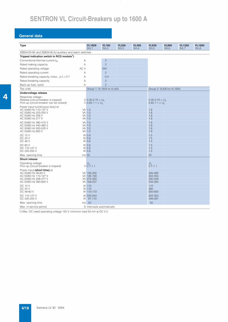
1) Max. DC rated operating voltage 125 V, minimum load 50 mA at DC 5 V.
Type VL160X3VL1
VL1603VL2
VL2503VL3
VL4003VL4
VL6303VL5
VL8003VL6
VL12503VL7
VL16003VL8
3SB34 00-0K and 3SB34 00-0J auxiliary and alarm switches
Tripped indication switch in RCD module1)
Conventional thermal current Ith A 2
Rated making capacity A 2
Rated operating voltage AC V 250
Rated operating current A 2
Rated breaking capacity, induc., p.f.= 0.7 A 0.5
Rated breaking capacity A 2
Back-up fuse, quick A 2
Trip units Group 1: VL160X to VL400 Group 2: VL630 to VL1600
Undervoltage release
Response voltage:Release (circuit-breaker is tripped) V 0.35-0.70 × Us 0.35-0.70 × UsPick-up (circuit-breaker can be closed) V 0.85-1.1 × Us 0.85-1.1 × Us
Power input (continuous duty) at:AC 50/60 Hz 110-127 V VA 1.0 1.8AC 50/60 Hz 220-250 V VA 1.0 1.8AC 50/60 Hz 208 V VA 1.0 1.8AC 50/60 Hz 277 V VA 1.0 1.8
AC 50/60 Hz 380-415 V VA 1.0 1.8AC 50/60 Hz 440-480 V VA 1.0 1.8AC 50/60 Hz 500-525 V VA 1.0 1.8AC 50/60 Hz 600 V VA 1.0 1.8
DC 12 V W 0.8 1.5DC 24 V W 0.8 1.5DC 48 V W 0.8 1.5
DC 60 V W 0.8 1.5DC 110-127 V W 0.8 1.5DC 220-250 V W 0.8 1.5
Max. opening time ms 50 50
Shunt release
Operating voltage: Us UsPick-up (circuit-breaker is tripped) V 0.7-1.1 0.7-1.1
Power input (short time) at:AC 50/60 Hz 48-60 V VA 158-200 300-480AC 50/60 Hz 110-127 V VA 136-158 302-353AC 50/60 Hz 208-277 V VA 274-350 330-349AC 50/60 Hz 380-600 V VA 158-237 243-384
DC 12 V W 110 110DC 24 V W 110 360DC 48-60 V W 110-172 500-820
DC 110-127 V W 220-254 302-353DC 220-250 V W 97-110 348-397
Max. opening time ms 50 50
Max. in-service period S interrupts automatically
Siemens LV 30 · 2004 4/19
SENTRON VL Circuit-Breakers up to 1600 A
General data
4
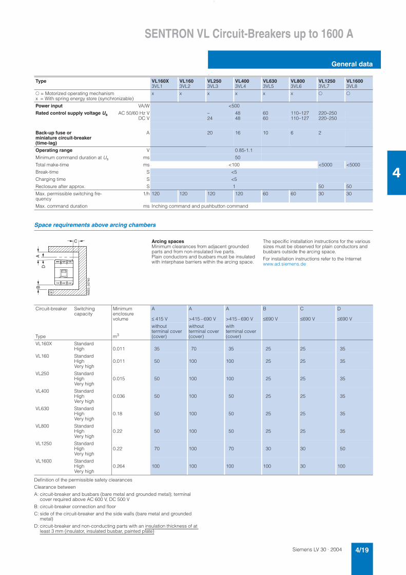
o
Space requirements above arcing chambers
Definition of the permissible safety clearances
Clearance between
A: circuit-breaker and busbars (bare metal and grounded metal); terminal cover required above AC 600 V, DC 500 V
B: circuit-breaker connection and floor
C: side of the circuit-breaker and the side walls (bare metal and grounded metal)
D: circuit-breaker and non-conducting parts with an insulation thickness of at least 3 mm (insulator, insulated busbar, painted plate)
Type VL160X3VL1
VL1603VL2
VL2503VL3
VL4003VL4
VL6303VL5
VL8003VL6
VL12503VL7
VL16003VL8
- = Motorized operating mechanismx = With spring energy store (synchronizable)
x x x x x x , ,
Power input VA/W <500
Rated control supply voltage Us AC 50/60 Hz V – 48 60 110–127 220–250DC V 24 48 60 110–127 220–250
Back-up fuse or miniature circuit-breaker (time-lag)
A 20 16 10 6 2
Operating range V 0.85-1.1
Minimum command duration at Us ms 50
Total make-time ms <100 <5000 <5000
Break-time S <5
Charging time S <5
Reclosure after approx. S 1 50 50
Max. permissible switching fre-quency
1/h 120 120 120 120 60 60 30 30
Max. command duration ms Inching command and pushbutton command
Arcing spacesMinimum clearances from adjacent grounded parts and from non-insulated live parts. Plain conductors and busbars must be insulated with interphase barriers within the arcing space.
The specific installation instructions for the various sizes must be observed for plain conductors and busbars outside the arcing space.
For installation instructions refer to the Internet www.ad.siemens.de
Circuit-breaker Switchingcapacity
Minimumenclosure volume
A
≤ 415 V
A
>415 – 690 V
A
>415 – 690 V
B
≤690 V
C
≤690 V
D
≤690 V
Type m3
withoutterminal cover (cover)
withoutterminal cover (cover)
with terminal cover (cover)
VL160X StandardHigh 0.011 35 70 35 25 25 35
VL160 StandardHighVery high
0.011 50 100 100 25 25 35
VL250 StandardHighVery high
0.015 50 100 100 25 25 35
VL400 StandardHighVery high
0.036 50 100 50 25 25 35
VL630 StandardHighVery high
0.18 50 100 50 25 25 35
VL800 StandardHighVery high
0.22 50 100 50 25 25 35
VL1250 StandardHighVery high
0.22 70 100 70 30 30 50
VL1600 StandardHighVery high
0.264 100 100 100 100 30 100
C
BA
NS
E0_
0074
0
D
Siemens LV 30 · 20044/20
SENTRON VL Circuit-Breakers up to 1600 A
General data
4
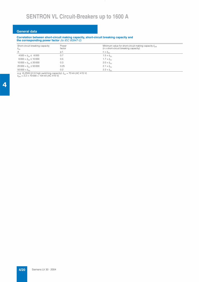
Correlation between short-circuit making capacity, short-circuit breaking capacity and the corresponding power factor (to IEC 60947-2)
Short-circuit breaking capacity Icu
Powerfactor
Minimum value for short-circuit making capacity Icm(n x short-circuit breaking capacity)
A p.f. n × Icu
4 500 < Icu ≤ 6 000 0.7 1.5 × Icu
6 000 < Icu ≤ 10 000 0.5 1.7 × Icu
10 000 < Icu ≤ 20 000 0.3 2.0 × Icu
20 000 < Icu ≤ 50 000 0.25 2.1 × Icu
50 000 < Icu 0.2 2.2 × Icu
e.g. VL250H (H r high switching capacity): Icu = 70 kA (AC 415 V)Icm = 2.2 × 70 000 = 154 kA (AC 415 V)
Siemens LV 30 · 2004 4/21
SENTRON VL Circuit-Breakers up to 1600 A
General data
4
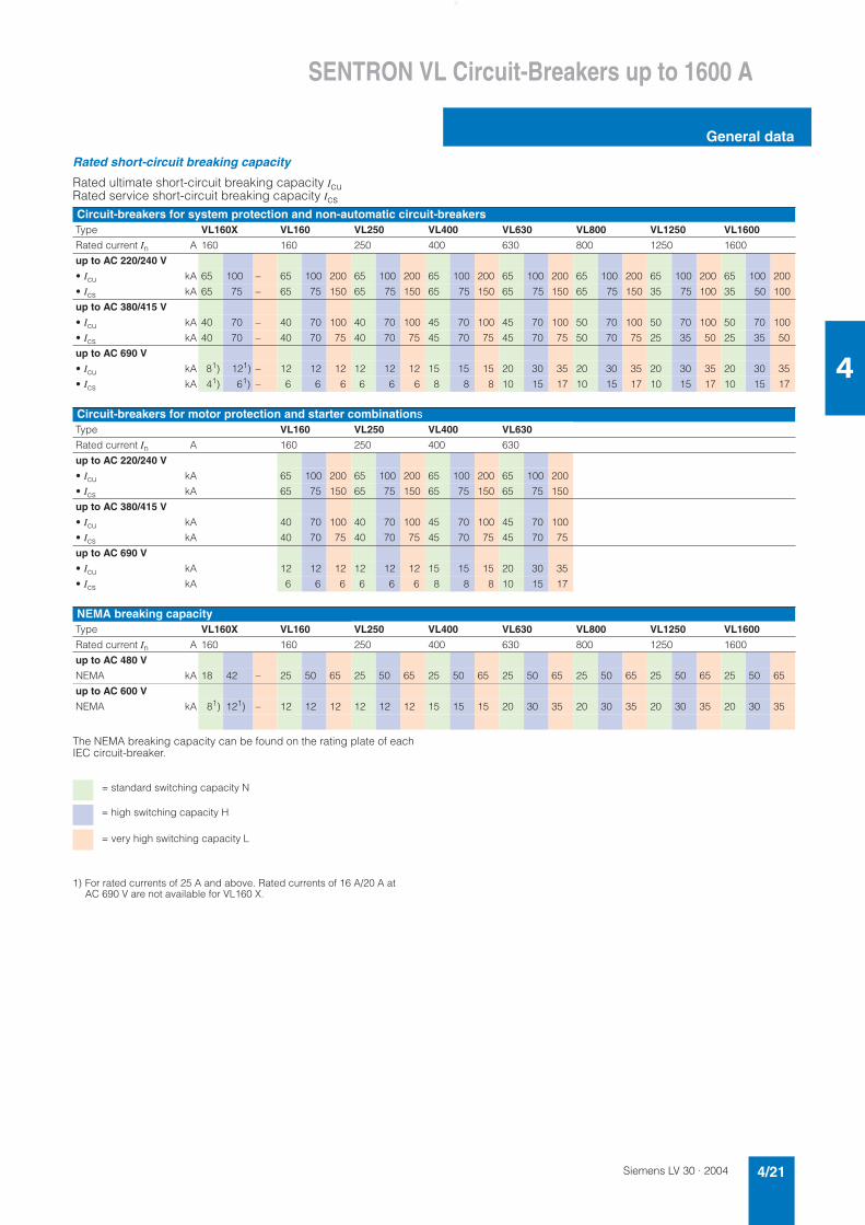
Rated short-circuit breaking capacity
Rated ultimate short-circuit breaking capacity IcuRated service short-circuit breaking capacity Ics
The NEMA breaking capacity can be found on the rating plate of each IEC circuit-breaker.
1) For rated currents of 25 A and above. Rated currents of 16 A/20 A at AC 690 V are not available for VL160 X.
Circuit-breakers for system protection and non-automatic circuit-breakersType VL160X VL160 VL250 VL400 VL630 VL800 VL1250 VL1600
Rated current In A 160 160 250 400 630 800 1250 1600
up to AC 220/240 V
• Icu kA 65 100 – 65 100 200 65 100 200 65 100 200 65 100 200 65 100 200 65 100 200 65 100 200
• Ics kA 65 75 – 65 75 150 65 75 150 65 75 150 65 75 150 65 75 150 35 75 100 35 50 100
up to AC 380/415 V
• Icu kA 40 70 – 40 70 100 40 70 100 45 70 100 45 70 100 50 70 100 50 70 100 50 70 100
• Ics kA 40 70 – 40 70 75 40 70 75 45 70 75 45 70 75 50 70 75 25 35 50 25 35 50
up to AC 690 V
• Icu kA 81) 121) – 12 12 12 12 12 12 15 15 15 20 30 35 20 30 35 20 30 35 20 30 35
• Ics kA 41) 61) – 6 6 6 6 6 6 8 8 8 10 15 17 10 15 17 10 15 17 10 15 17
Circuit-breakers for motor protection and starter combinationsType VL160 VL250 VL400 VL630
Rated current In A 160 250 400 630
up to AC 220/240 V
• Icu kA 65 100 200 65 100 200 65 100 200 65 100 200
• Ics kA 65 75 150 65 75 150 65 75 150 65 75 150
up to AC 380/415 V
• Icu kA 40 70 100 40 70 100 45 70 100 45 70 100
• Ics kA 40 70 75 40 70 75 45 70 75 45 70 75
up to AC 690 V
• Icu kA 12 12 12 12 12 12 15 15 15 20 30 35
• Ics kA 6 6 6 6 6 6 8 8 8 10 15 17
NEMA breaking capacityType VL160X VL160 VL250 VL400 VL630 VL800 VL1250 VL1600
Rated current In A 160 160 250 400 630 800 1250 1600
up to AC 480 V
NEMA kA 18 42 – 25 50 65 25 50 65 25 50 65 25 50 65 25 50 65 25 50 65 25 50 65
up to AC 600 V
NEMA kA 81) 121) – 12 12 12 12 12 12 15 15 15 20 30 35 20 30 35 20 30 35 20 30 35
= standard switching capacity N
= high switching capacity H
= very high switching capacity L
Siemens LV 30 · 20044/22
SENTRON VL Circuit-Breakers up to 1600 A
3-pole
4
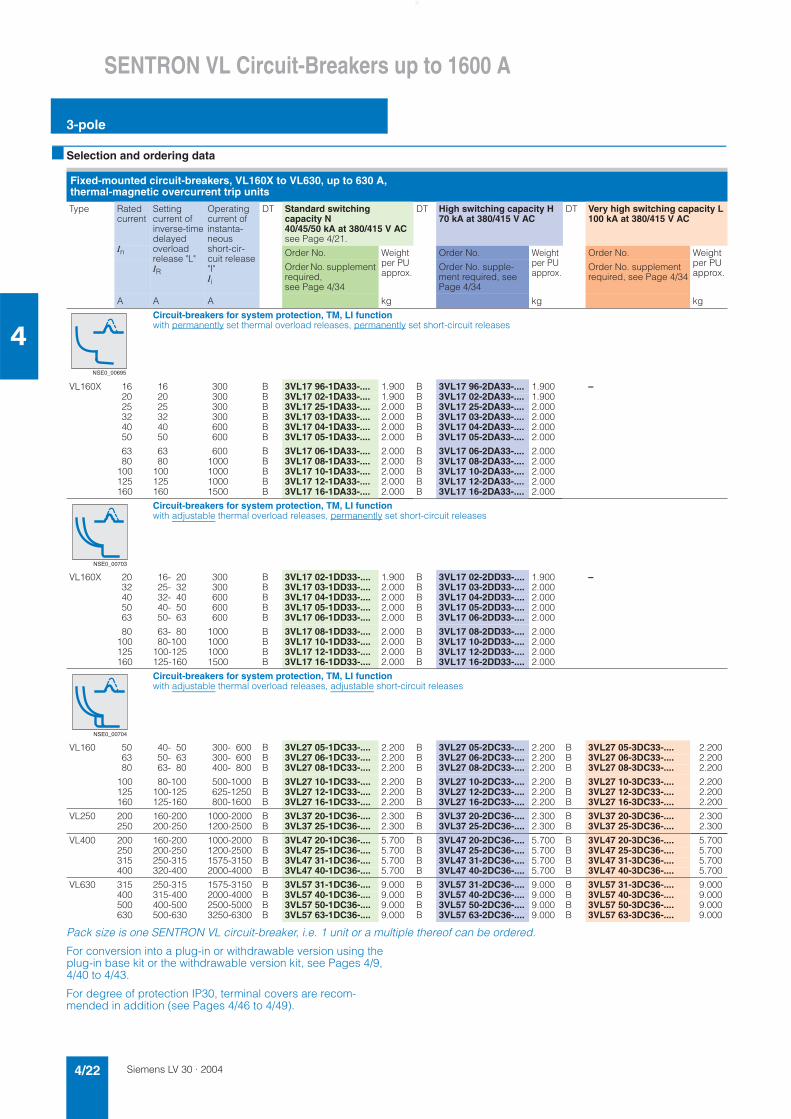
■ Selection and ordering data
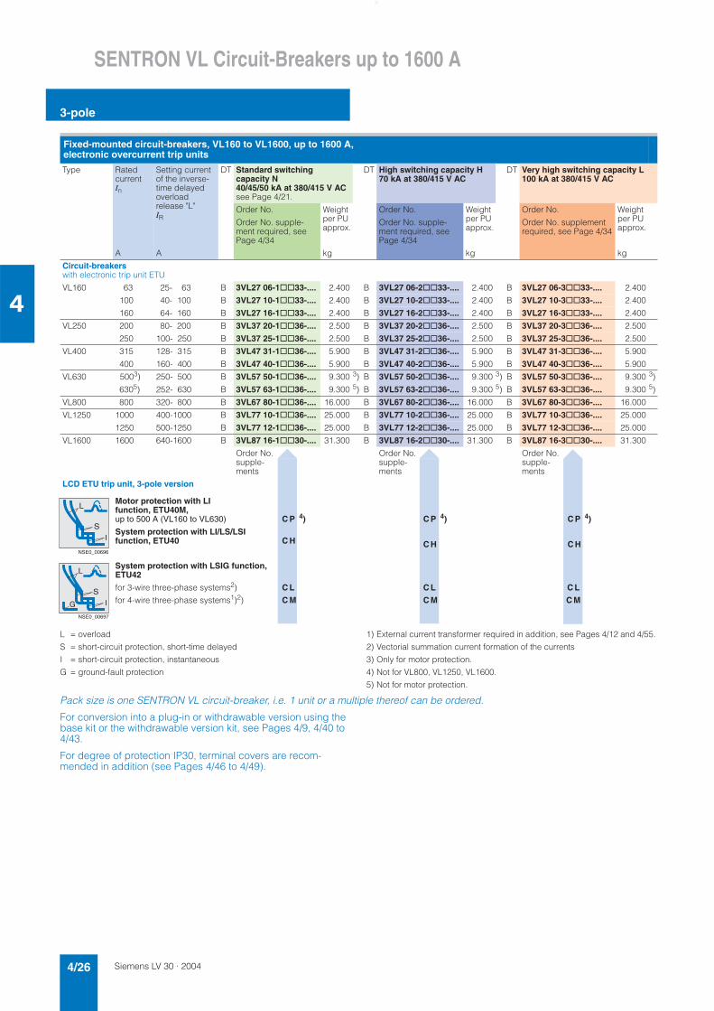
Pack size is one SENTRON VL circuit-breaker, i.e. 1 unit or a multiple thereof can be ordered.
For conversion into a plug-in or withdrawable version using the plug-in base kit or the withdrawable version kit, see Pages 4/9, 4/40 to 4/43.
For degree of protection IP30, terminal covers are recom-mended in addition (see Pages 4/46 to 4/49).
Fixed-mounted circuit-breakers, VL160X to VL630, up to 630 A, thermal-magnetic overcurrent trip units
Type Ratedcurrent
Settingcurrent of inverse-timedelayedoverloadrelease "L"IR
Operating current of instanta-neousshort-cir-cuit release "I"Ii
DT Standard switching capacity N40/45/50 kA at 380/415 V ACsee Page 4/21.
DT High switching capacity H 70 kA at 380/415 V AC
DT Very high switching capacity L 100 kA at 380/415 V AC
In Order No. Weight per PU approx.
Order No. Weight per PU approx.
Order No. Weight per PU approx.
Order No. supplement required, see Page 4/34
Order No. supple-ment required, see Page 4/34
Order No. supplement required, see Page 4/34
A A A kg kg kg
Circuit-breakers for system protection, TM, LI function with permanently set thermal overload releases, permanently set short-circuit releases
VL160X 16 16 300 B 3VL17 96-1DA33-.... 1.900 B 3VL17 96-2DA33-.... 1.900 –20 20 300 B 3VL17 02-1DA33-.... 1.900 B 3VL17 02-2DA33-.... 1.900 25 25 300 B 3VL17 25-1DA33-.... 2.000 B 3VL17 25-2DA33-.... 2.000 32 32 300 B 3VL17 03-1DA33-.... 2.000 B 3VL17 03-2DA33-.... 2.000 40 40 600 B 3VL17 04-1DA33-.... 2.000 B 3VL17 04-2DA33-.... 2.000 50 50 600 B 3VL17 05-1DA33-.... 2.000 B 3VL17 05-2DA33-.... 2.000
63 63 600 B 3VL17 06-1DA33-.... 2.000 B 3VL17 06-2DA33-.... 2.000 80 80 1000 B 3VL17 08-1DA33-.... 2.000 B 3VL17 08-2DA33-.... 2.000
100 100 1000 B 3VL17 10-1DA33-.... 2.000 B 3VL17 10-2DA33-.... 2.000 125 125 1000 B 3VL17 12-1DA33-.... 2.000 B 3VL17 12-2DA33-.... 2.000 160 160 1500 B 3VL17 16-1DA33-.... 2.000 B 3VL17 16-2DA33-.... 2.000
Circuit-breakers for system protection, TM, LI function with adjustable thermal overload releases, permanently set short-circuit releases
VL160X 20 16- 20 300 B 3VL17 02-1DD33-.... 1.900 B 3VL17 02-2DD33-.... 1.900 –32 25- 32 300 B 3VL17 03-1DD33-.... 2.000 B 3VL17 03-2DD33-.... 2.000 40 32- 40 600 B 3VL17 04-1DD33-.... 2.000 B 3VL17 04-2DD33-.... 2.000 50 40- 50 600 B 3VL17 05-1DD33-.... 2.000 B 3VL17 05-2DD33-.... 2.000 63 50- 63 600 B 3VL17 06-1DD33-.... 2.000 B 3VL17 06-2DD33-.... 2.000
80 63- 80 1000 B 3VL17 08-1DD33-.... 2.000 B 3VL17 08-2DD33-.... 2.000 100 80-100 1000 B 3VL17 10-1DD33-.... 2.000 B 3VL17 10-2DD33-.... 2.000 125 100-125 1000 B 3VL17 12-1DD33-.... 2.000 B 3VL17 12-2DD33-.... 2.000 160 125-160 1500 B 3VL17 16-1DD33-.... 2.000 B 3VL17 16-2DD33-.... 2.000
Circuit-breakers for system protection, TM, LI function with adjustable thermal overload releases, adjustable short-circuit releases
VL160 50 40- 50 300- 600 B 3VL27 05-1DC33-.... 2.200 B 3VL27 05-2DC33-.... 2.200 B 3VL27 05-3DC33-.... 2.20063 50- 63 300- 600 B 3VL27 06-1DC33-.... 2.200 B 3VL27 06-2DC33-.... 2.200 B 3VL27 06-3DC33-.... 2.20080 63- 80 400- 800 B 3VL27 08-1DC33-.... 2.200 B 3VL27 08-2DC33-.... 2.200 B 3VL27 08-3DC33-.... 2.200
100 80-100 500-1000 B 3VL27 10-1DC33-.... 2.200 B 3VL27 10-2DC33-.... 2.200 B 3VL27 10-3DC33-.... 2.200125 100-125 625-1250 B 3VL27 12-1DC33-.... 2.200 B 3VL27 12-2DC33-.... 2.200 B 3VL27 12-3DC33-.... 2.200160 125-160 800-1600 B 3VL27 16-1DC33-.... 2.200 B 3VL27 16-2DC33-.... 2.200 B 3VL27 16-3DC33-.... 2.200
VL250 200 160-200 1000-2000 B 3VL37 20-1DC36-.... 2.300 B 3VL37 20-2DC36-.... 2.300 B 3VL37 20-3DC36-.... 2.300250 200-250 1200-2500 B 3VL37 25-1DC36-.... 2.300 B 3VL37 25-2DC36-.... 2.300 B 3VL37 25-3DC36-.... 2.300
VL400 200 160-200 1000-2000 B 3VL47 20-1DC36-.... 5.700 B 3VL47 20-2DC36-.... 5.700 B 3VL47 20-3DC36-.... 5.700250 200-250 1200-2500 B 3VL47 25-1DC36-.... 5.700 B 3VL47 25-2DC36-.... 5.700 B 3VL47 25-3DC36-.... 5.700315 250-315 1575-3150 B 3VL47 31-1DC36-.... 5.700 B 3VL47 31-2DC36-.... 5.700 B 3VL47 31-3DC36-.... 5.700400 320-400 2000-4000 B 3VL47 40-1DC36-.... 5.700 B 3VL47 40-2DC36-.... 5.700 B 3VL47 40-3DC36-.... 5.700
VL630 315 250-315 1575-3150 B 3VL57 31-1DC36-.... 9.000 B 3VL57 31-2DC36-.... 9.000 B 3VL57 31-3DC36-.... 9.000400 315-400 2000-4000 B 3VL57 40-1DC36-.... 9.000 B 3VL57 40-2DC36-.... 9.000 B 3VL57 40-3DC36-.... 9.000500 400-500 2500-5000 B 3VL57 50-1DC36-.... 9.000 B 3VL57 50-2DC36-.... 9.000 B 3VL57 50-3DC36-.... 9.000630 500-630 3250-6300 B 3VL57 63-1DC36-.... 9.000 B 3VL57 63-2DC36-.... 9.000 B 3VL57 63-3DC36-.... 9.000
NSE0_00695
NSE0_00703
NSE0_00704
Siemens LV 30 · 2004 4/23
SENTRON VL Circuit-Breakers up to 1600 A
3-pole
4
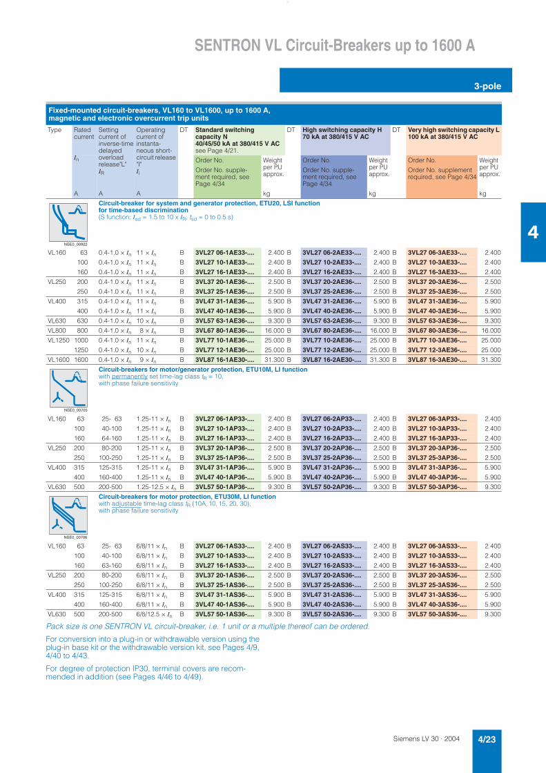
Pack size is one SENTRON VL circuit-breaker, i.e. 1 unit or a multiple thereof can be ordered.
For conversion into a plug-in or withdrawable version using the plug-in base kit or the withdrawable version kit, see Pages 4/9, 4/40 to 4/43.
For degree of protection IP30, terminal covers are recom-mended in addition (see Pages 4/46 to 4/49).
Fixed-mounted circuit-breakers, VL160 to VL1600, up to 1600 A, magnetic and electronic overcurrent trip units
Type Ratedcurrent
Settingcurrent of inverse-timedelayedoverloadrelease"L"IR
Operating current of instanta-neous short-circuit release "I"Ii
DT Standard switching capacity N 40/45/50 kA at 380/415 V ACsee Page 4/21.
DT High switching capacity H 70 kA at 380/415 V AC
DT Very high switching capacity L 100 kA at 380/415 V AC
In Order No. Weight per PU approx.
Order No. Weight per PU approx.
Order No. Weight per PU approx.
Order No. supple-ment required, see Page 4/34
Order No. supple-ment required, see Page 4/34
Order No. supplement required, see Page 4/34
A A A kg kg kg
Circuit-breaker for system and generator protection, ETU20, LSI functionfor time-based discrimination (S function: Isd = 1.5 to 10 x IR, tsd = 0 to 0.5 s)
VL160 63 0.4-1.0 × In 11 × In B 3VL27 06-1AE33-.... 2.400 B 3VL27 06-2AE33-.... 2.400 B 3VL27 06-3AE33-.... 2.400
100 0.4-1.0 × In 11 × In B 3VL27 10-1AE33-.... 2.400 B 3VL27 10-2AE33-.... 2.400 B 3VL27 10-3AE33-.... 2.400
160 0.4-1.0 × In 11 × In B 3VL27 16-1AE33-.... 2.400 B 3VL27 16-2AE33-.... 2.400 B 3VL27 16-3AE33-.... 2.400
VL250 200 0.4-1.0 × In 11 × In B 3VL37 20-1AE36-.... 2.500 B 3VL37 20-2AE36-.... 2.500 B 3VL37 20-3AE36-.... 2.500
250 0.4-1.0 × In 11 × In B 3VL37 25-1AE36-.... 2.500 B 3VL37 25-2AE36-.... 2.500 B 3VL37 25-3AE36-.... 2.500
VL400 315 0.4-1.0 × In 11 × In B 3VL47 31-1AE36-.... 5.900 B 3VL47 31-2AE36-.... 5.900 B 3VL47 31-3AE36-.... 5.900
400 0.4-1.0 × In 11 × In B 3VL47 40-1AE36-.... 5.900 B 3VL47 40-2AE36-.... 5.900 B 3VL47 40-3AE36-.... 5.900
VL630 630 0.4-1.0 × In 10 × In B 3VL57 63-1AE36-.... 9.300 B 3VL57 63-2AE36-.... 9.300 B 3VL57 63-3AE36-.... 9.300
VL800 800 0.4-1.0 × In 8 × In B 3VL67 80-1AE36-.... 16.000 B 3VL67 80-2AE36-.... 16.000 B 3VL67 80-3AE36-.... 16.000
VL1250 1000 0.4-1.0 × In 11 × In B 3VL77 10-1AE36-.... 25.000 B 3VL77 10-2AE36-.... 25.000 B 3VL77 10-3AE36-.... 25.000
1250 0.4-1.0 × In 10 × In B 3VL77 12-1AE36-.... 25.000 B 3VL77 12-2AE36-.... 25.000 B 3VL77 12-3AE36-.... 25.000
VL1600 1600 0.4-1.0 × In 9 × In B 3VL87 16-1AE30-.... 31.300 B 3VL87 16-2AE30-.... 31.300 B 3VL87 16-3AE30-.... 31.300
Circuit-breakers for motor/generator protection, ETU10M, LI functionwith permanently set time-lag class tR = 10, with phase failure sensitivity
VL160 63 25- 63 1.25-11 × In B 3VL27 06-1AP33-.... 2.400 B 3VL27 06-2AP33-.... 2.400 B 3VL27 06-3AP33-.... 2.400
100 40-100 1.25-11 × In B 3VL27 10-1AP33-.... 2.400 B 3VL27 10-2AP33-.... 2.400 B 3VL27 10-3AP33-.... 2.400
160 64-160 1.25-11 × In B 3VL27 16-1AP33-.... 2.400 B 3VL27 16-2AP33-.... 2.400 B 3VL27 16-3AP33-.... 2.400
VL250 200 80-200 1.25-11 × In B 3VL37 20-1AP36-.... 2.500 B 3VL37 20-2AP36-.... 2.500 B 3VL37 20-3AP36-.... 2.500
250 100-250 1.25-11 × In B 3VL37 25-1AP36-.... 2.500 B 3VL37 25-2AP36-.... 2.500 B 3VL37 25-3AP36-.... 2.500
VL400 315 125-315 1.25-11 × In B 3VL47 31-1AP36-.... 5.900 B 3VL47 31-2AP36-.... 5.900 B 3VL47 31-3AP36-.... 5.900
400 160-400 1.25-11 × In B 3VL47 40-1AP36-.... 5.900 B 3VL47 40-2AP36-.... 5.900 B 3VL47 40-3AP36-.... 5.900
VL630 500 200-500 1.25-12.5 × In B 3VL57 50-1AP36-.... 9.300 B 3VL57 50-2AP36-.... 9.300 B 3VL57 50-3AP36-.... 9.300
Circuit-breakers for motor protection, ETU30M, LI functionwith adjustable time-lag class tR (10A, 10, 15, 20, 30), with phase failure sensitivity
VL160 63 25- 63 6/8/11 × In B 3VL27 06-1AS33-.... 2.400 B 3VL27 06-2AS33-.... 2.400 B 3VL27 06-3AS33-.... 2.400
100 40-100 6/8/11 × In B 3VL27 10-1AS33-.... 2.400 B 3VL27 10-2AS33-.... 2.400 B 3VL27 10-3AS33-.... 2.400
160 63-160 6/8/11 × In B 3VL27 16-1AS33-.... 2.400 B 3VL27 16-2AS33-.... 2.400 B 3VL27 16-3AS33-.... 2.400
VL250 200 80-200 6/8/11 × In B 3VL37 20-1AS36-.... 2.500 B 3VL37 20-2AS36-.... 2.500 B 3VL37 20-3AS36-.... 2.500
250 100-250 6/8/11 × In B 3VL37 25-1AS36-.... 2.500 B 3VL37 25-2AS36-.... 2.500 B 3VL37 25-3AS36-.... 2.500
VL400 315 125-315 6/8/11 × In B 3VL47 31-1AS36-.... 5.900 B 3VL47 31-2AS36-.... 5.900 B 3VL47 31-3AS36-.... 5.900
400 160-400 6/8/11 × In B 3VL47 40-1AS36-.... 5.900 B 3VL47 40-2AS36-.... 5.900 B 3VL47 40-3AS36-.... 5.900
VL630 500 200-500 6/8/12.5 × In B 3VL57 50-1AS36-.... 9.300 B 3VL57 50-2AS36-.... 9.300 B 3VL57 50-3AS36-.... 9.300
NSE0_00922
NSE0_00705
NSE0_00706
Siemens LV 30 · 20044/24
SENTRON VL Circuit-Breakers up to 1600 A
3-pole
4
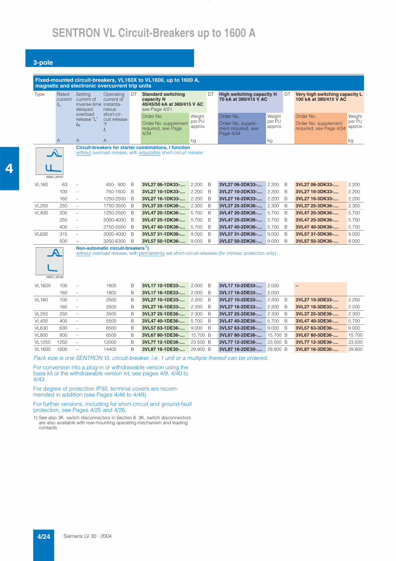
Pack size is one SENTRON VL circuit-breaker, i.e. 1 unit or a multiple thereof can be ordered.
For conversion into a plug-in or withdrawable version using the base kit or the withdrawable version kit, see pages 4/9, 4/40 to 4/43.
For degree of protection IP30, terminal covers are recom-mended in addition (see Pages 4/46 to 4/49).
For further versions, including for short-circuit and ground-fault protection, see Pages 4/25 and 4/26.1) See also 3K. switch disconnectors in Section 6. 3K. switch disconnectors
are also available with rear-mounting operating mechanism and leading contacts.
Fixed-mounted circuit-breakers, VL160X to VL1600, up to 1600 A, magnetic and electronic overcurrent trip units
Type Ratedcurrent In
Settingcurrent of inverse-timedelayed overloadrelease "L"IR
Operating current of instanta-neousshort-cir-cuit release "I"Ii
DT Standard switching capacity N 40/45/50 kA at 380/415 V ACsee Page 4/21.
DT High switching capacity H 70 kA at 380/415 V AC
DT Very high switching capacity L 100 kA at 380/415 V AC
Order No. Weight per PU approx.
Order No. Weight per PU approx.
Order No. Weight per PU approx.
Order No. supplement required, see Page 4/34
Order No. supple-ment required, see Page 4/34
Order No. supplement required, see Page 4/34
A A A kg kg kg
Circuit-breakers for starter combinations, I functionwithout overload release, with adjustable short-circuit release
VL160 63 – 450- 900 B 3VL27 06-1DK33-.... 2.200 B 3VL27 06-2DK33-.... 2.200 B 3VL27 06-3DK33-.... 2.200
100 – 750-1500 B 3VL27 10-1DK33-.... 2.200 B 3VL27 10-2DK33-.... 2.200 B 3VL27 10-3DK33-.... 2.200
160 – 1250-2500 B 3VL27 16-1DK33-.... 2.200 B 3VL27 16-2DK33-.... 2.200 B 3VL27 16-3DK33-.... 2.200
VL250 250 – 1750-3500 B 3VL37 25-1DK36-.... 2.300 B 3VL37 25-2DK36-.... 2.300 B 3VL37 25-3DK36-.... 2.300
VL400 200 – 1250-2500 B 3VL47 20-1DK36-.... 5.700 B 3VL47 20-2DK36-.... 5.700 B 3VL47 20-3DK36-.... 5.700
250 – 2000-4000 B 3VL47 25-1DK36-.... 5.700 B 3VL47 25-2DK36-.... 5.700 B 3VL47 25-3DK36-.... 5.700
400 – 2750-5500 B 3VL47 40-1DK36-.... 5.700 B 3VL47 40-2DK36-.... 5.700 B 3VL47 40-3DK36-.... 5.700
VL630 315 – 2000-4000 B 3VL57 31-1DK36-.... 9.000 B 3VL57 31-2DK36-.... 9.000 B 3VL57 31-3DK36-.... 9.000
500 – 3250-6300 B 3VL57 50-1DK36-.... 9.000 B 3VL57 50-2DK36-.... 9.000 B 3VL57 50-3DK36-.... 9.000
Non-automatic circuit-breakers1)without overload release, with permanently set short-circuit releases (for intrinsic protection only)
VL160X 100 – 1800 B 3VL17 10-1DE33-.... 2.000 B 3VL17 10-2DE33-.... 2.000 –
160 – 1800 B 3VL17 16-1DE33-.... 2.000 B 3VL17 16-2DE33-.... 2.000
VL160 100 – 2500 B 3VL27 10-1DE33-.... 2.200 B 3VL27 10-2DE33-.... 2.200 B 3VL27 10-3DE33-.... 2.200
160 – 2500 B 3VL27 16-1DE33-.... 2.200 B 3VL27 16-2DE33-.... 2.200 B 3VL27 16-3DE33-.... 2.200
VL250 250 – 3500 B 3VL37 25-1DE36-.... 2.300 B 3VL37 25-2DE36-.... 2.300 B 3VL37 25-3DE36-.... 2.300
VL400 400 – 5500 B 3VL47 40-1DE36-.... 5.700 B 3VL47 40-2DE36-.... 5.700 B 3VL47 40-3DE36-.... 5.700
VL630 630 – 6500 B 3VL57 63-1DE36-.... 9.000 B 3VL57 63-2DE36-.... 9.000 B 3VL57 63-3DE36-.... 9.000
VL800 800 – 6500 B 3VL67 80-1DE36-.... 15.700 B 3VL67 80-2DE36-.... 15.700 B 3VL67 80-3DE36-.... 15.700
VL1250 1250 – 12000 B 3VL77 12-1DE36-.... 23.500 B 3VL77 12-2DE36-.... 23.500 B 3VL77 12-3DE36-.... 23.500
VL1600 1600 – 14400 B 3VL87 16-1DE30-.... 29.800 B 3VL87 16-2DE30-.... 29.800 B 3VL87 16-3DE30-.... 29.800
NSE0_00707
NSE0_00708
Siemens LV 30 · 2004 4/25
SENTRON VL Circuit-Breakers up to 1600 A
3-pole
4
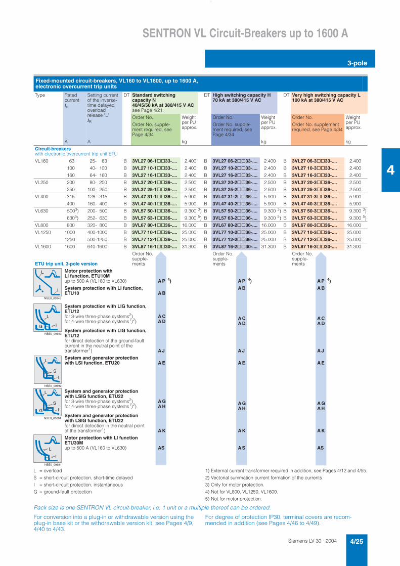
L = overload
S = short-circuit protection, short-time delayed
I = short-circuit protection, instantaneous
G = ground-fault protection
1) External current transformer required in addition, see Pages 4/12 and 4/55.
2) Vectorial summation current formation of the currents
3) Only for motor protection.
4) Not for VL800, VL1250, VL1600.
5) Not for motor protection.
Pack size is one SENTRON VL circuit-breaker, i.e. 1 unit or a multiple thereof can be ordered.
For conversion into a plug-in or withdrawable version using the plug-in base kit or the withdrawable version kit, see Pages 4/9, 4/40 to 4/43.
For degree of protection IP30, terminal covers are recom-mended in addition (see Pages 4/46 to 4/49).
Fixed-mounted circuit-breakers, VL160 to VL1600, up to 1600 A, electronic overcurrent trip units
Type Ratedcurrent In
Setting current of the inverse-time delayed overload release "L" IR
DT Standard switching capacity N 40/45/50 kA at 380/415 V ACsee Page 4/21.
DT High switching capacity H 70 kA at 380/415 V AC
DT Very high switching capacity L 100 kA at 380/415 V AC
Order No. Weight per PU approx.
Order No. Weight per PU approx.
Order No. Weight per PU approx.
Order No. supple-ment required, see Page 4/34
Order No. supple-ment required, see Page 4/34
Order No. supplement required, see Page 4/34
A A kg kg kg
Circuit-breakerswith electronic overcurrent trip unit ETU
VL160 63 25- 63 B 3VL27 06-1@@33-.... 2.400 B 3VL27 06-2@@33-.... 2.400 B 3VL27 06-3@@33-.... 2.400
100 40- 100 B 3VL27 10-1@@33-.... 2.400 B 3VL27 10-2@@33-.... 2.400 B 3VL27 10-3@@33-.... 2.400
160 64- 160 B 3VL27 16-1@@33-.... 2.400 B 3VL27 16-2@@33-.... 2.400 B 3VL27 16-3@@33-.... 2.400
VL250 200 80- 200 B 3VL37 20-1@@36-.... 2.500 B 3VL37 20-2@@36-.... 2.500 B 3VL37 20-3@@36-.... 2.500
250 100- 250 B 3VL37 25-1@@36-.... 2.500 B 3VL37 25-2@@36-.... 2.500 B 3VL37 25-3@@36-.... 2.500
VL400 315 128- 315 B 3VL47 31-1@@36-.... 5.900 B 3VL47 31-2@@36-.... 5.900 B 3VL47 31-3@@36-.... 5.900
400 160- 400 B 3VL47 40-1@@36-.... 5.900 B 3VL47 40-2@@36-.... 5.900 B 3VL47 40-3@@36-.... 5.900
VL630 5003) 200- 500 B 3VL57 50-1@@36-.... 9.300 3) B 3VL57 50-2@@36-.... 9.300 3) B 3VL57 50-3@@36-.... 9.300 3)
6305) 252- 630 B 3VL57 63-1@@36-.... 9.300 5) B 3VL57 63-2@@36-.... 9.300 5) B 3VL57 63-3@@36-.... 9.300 5)
VL800 800 320- 800 B 3VL67 80-1@@36-.... 16.000 B 3VL67 80-2@@36-.... 16.000 B 3VL67 80-3@@36-.... 16.000
VL1250 1000 400-1000 B 3VL77 10-1@@36-.... 25.000 B 3VL77 10-2@@36-.... 25.000 B 3VL77 10-3@@36-.... 25.000
1250 500-1250 B 3VL77 12-1@@36-.... 25.000 B 3VL77 12-2@@36-.... 25.000 B 3VL77 12-3@@36-.... 25.000
VL1600 1600 640-1600 B 3VL87 16-1@@30-.... 31.300 B 3VL87 16-2@@30-.... 31.300 B 3VL87 16-3@@30-.... 31.300
ETU trip unit, 3-pole version
Order No. supple-ments
Order No. supple-ments
Order No. supple-ments
Motor protection with LI function, ETU10Mup to 500 A (VL160 to VL630) A P 4) A P 4) A P 4)
System protection with LI function, ETU10 A B
A B A B
System protection with LIG function, ETU12for 3-wire three-phase systems2) A Cfor 4-wire three-phase systems1)2) A D
A CA D
A CA D
System protection with LIG function, ETU12for direct detection of the ground-fault current in the neutral point of the transformer1) A J A J A J
System and generator protection with LSI function, ETU20 A E A E A E
System and generator protection with LSIG function, ETU22for 3-wire three-phase systems2) A Gfor 4-wire three-phase systems1)2) A H
A GA H
A GA H
System and generator protection with LSIG function, ETU22for direct detection in the neutral point of the transformer1) A K A K A K
Motor protection with LI function ETU30Mup to 500 A (VL160 to VL630) AS A S AS
NSE0_00943
L
I
L
IG
NSE0_00693
L
S
I
NSE0_00692
L
S
IG
NSE0_00694
L
I
NSE0_00691
Siemens LV 30 · 20044/26
SENTRON VL Circuit-Breakers up to 1600 A
3-pole
4
L = overload
S = short-circuit protection, short-time delayed
I = short-circuit protection, instantaneous
G = ground-fault protection
1) External current transformer required in addition, see Pages 4/12 and 4/55.
2) Vectorial summation current formation of the currents
3) Only for motor protection.
4) Not for VL800, VL1250, VL1600.
5) Not for motor protection.
Pack size is one SENTRON VL circuit-breaker, i.e. 1 unit or a multiple thereof can be ordered.
For conversion into a plug-in or withdrawable version using the base kit or the withdrawable version kit, see Pages 4/9, 4/40 to 4/43.
For degree of protection IP30, terminal covers are recom-mended in addition (see Pages 4/46 to 4/49).
Fixed-mounted circuit-breakers, VL160 to VL1600, up to 1600 A, electronic overcurrent trip units
Type Ratedcurrent In
Setting current of the inverse-time delayed overload release "L" IR
DT Standard switching capacity N 40/45/50 kA at 380/415 V ACsee Page 4/21.
DT High switching capacity H 70 kA at 380/415 V AC
DT Very high switching capacity L 100 kA at 380/415 V AC
Order No. Weight per PU approx.
Order No. Weight per PU approx.
Order No. Weight per PU approx.
Order No. supple-ment required, see Page 4/34
Order No. supple-ment required, see Page 4/34
Order No. supplement required, see Page 4/34
A A kg kg kg
Circuit-breakerswith electronic trip unit ETU
VL160 63 25- 63 B 3VL27 06-1@@33-.... 2.400 B 3VL27 06-2@@33-.... 2.400 B 3VL27 06-3@@33-.... 2.400
100 40- 100 B 3VL27 10-1@@33-.... 2.400 B 3VL27 10-2@@33-.... 2.400 B 3VL27 10-3@@33-.... 2.400
160 64- 160 B 3VL27 16-1@@33-.... 2.400 B 3VL27 16-2@@33-.... 2.400 B 3VL27 16-3@@33-.... 2.400
VL250 200 80- 200 B 3VL37 20-1@@36-.... 2.500 B 3VL37 20-2@@36-.... 2.500 B 3VL37 20-3@@36-.... 2.500
250 100- 250 B 3VL37 25-1@@36-.... 2.500 B 3VL37 25-2@@36-.... 2.500 B 3VL37 25-3@@36-.... 2.500
VL400 315 128- 315 B 3VL47 31-1@@36-.... 5.900 B 3VL47 31-2@@36-.... 5.900 B 3VL47 31-3@@36-.... 5.900
400 160- 400 B 3VL47 40-1@@36-.... 5.900 B 3VL47 40-2@@36-.... 5.900 B 3VL47 40-3@@36-.... 5.900
VL630 5003) 250- 500 B 3VL57 50-1@@36-.... 9.300 3) B 3VL57 50-2@@36-.... 9.300 3) B 3VL57 50-3@@36-.... 9.300 3)
6305) 252- 630 B 3VL57 63-1@@36-.... 9.300 5) B 3VL57 63-2@@36-.... 9.300 5) B 3VL57 63-3@@36-.... 9.300 5)
VL800 800 320- 800 B 3VL67 80-1@@36-.... 16.000 B 3VL67 80-2@@36-.... 16.000 B 3VL67 80-3@@36-.... 16.000
VL1250 1000 400-1000 B 3VL77 10-1@@36-.... 25.000 B 3VL77 10-2@@36-.... 25.000 B 3VL77 10-3@@36-.... 25.000
1250 500-1250 B 3VL77 12-1@@36-.... 25.000 B 3VL77 12-2@@36-.... 25.000 B 3VL77 12-3@@36-.... 25.000
VL1600 1600 640-1600 B 3VL87 16-1@@30-.... 31.300 B 3VL87 16-2@@30-.... 31.300 B 3VL87 16-3@@30-.... 31.300
Order No. supple-ments
Order No. supple-ments
Order No. supple-ments
LCD ETU trip unit, 3-pole version
Motor protection with LI function, ETU40M, up to 500 A (VL160 to VL630) C P 4) C P 4) C P 4)
System protection with LI/LS/LSI function, ETU40 C H C H C H
System protection with LSIG function, ETU42
for 3-wire three-phase systems2) C L
for 4-wire three-phase systems1)2) C M
C L
C M
C L
C M
L
S
I
NSE0_00696
L
S
IG
NSE0_00697
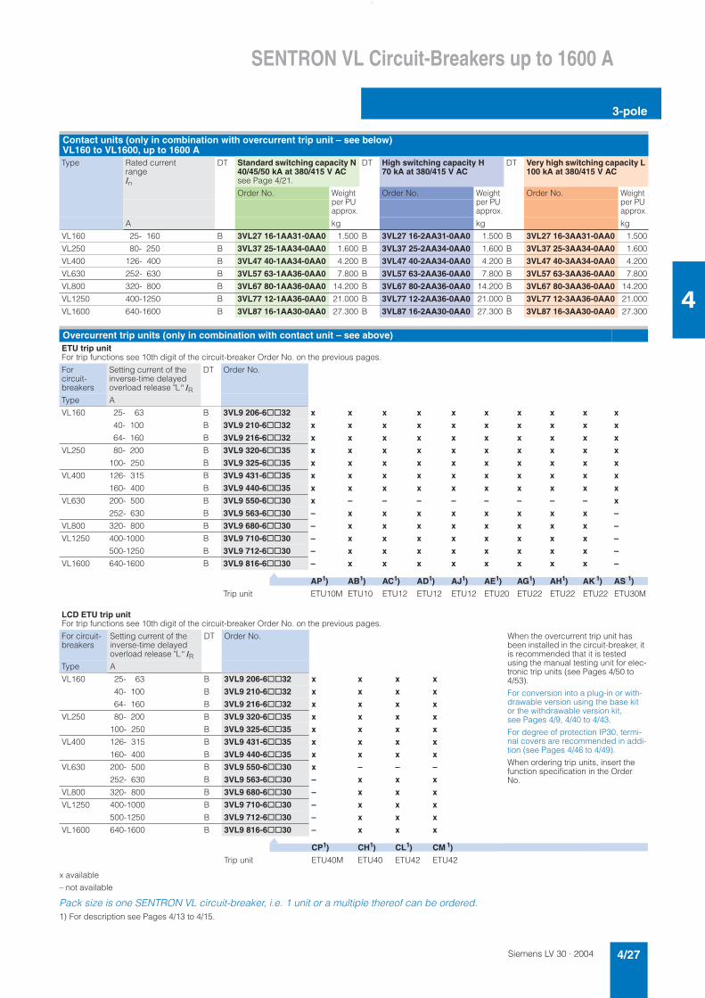
Siemens LV 30 · 2004 4/27
SENTRON VL Circuit-Breakers up to 1600 A
3-pole
4
x available
– not available
Pack size is one SENTRON VL circuit-breaker, i.e. 1 unit or a multiple thereof can be ordered.1) For description see Pages 4/13 to 4/15.
Contact units (only in combination with overcurrent trip unit – see below) VL160 to VL1600, up to 1600 AType Rated current
rangeIn
DT Standard switching capacity N 40/45/50 kA at 380/415 V AC see Page 4/21.
DT High switching capacity H 70 kA at 380/415 V AC
DT Very high switching capacity L 100 kA at 380/415 V AC
Order No. Weight per PU approx.
Order No. Weight per PU approx.
Order No. Weight per PU approx.
A kg kg kg
VL160 25- 160 B 3VL27 16-1AA31-0AA0 1.500 B 3VL27 16-2AA31-0AA0 1.500 B 3VL27 16-3AA31-0AA0 1.500
VL250 80- 250 B 3VL37 25-1AA34-0AA0 1.600 B 3VL37 25-2AA34-0AA0 1.600 B 3VL37 25-3AA34-0AA0 1.600
VL400 126- 400 B 3VL47 40-1AA34-0AA0 4.200 B 3VL47 40-2AA34-0AA0 4.200 B 3VL47 40-3AA34-0AA0 4.200
VL630 252- 630 B 3VL57 63-1AA36-0AA0 7.800 B 3VL57 63-2AA36-0AA0 7.800 B 3VL57 63-3AA36-0AA0 7.800
VL800 320- 800 B 3VL67 80-1AA36-0AA0 14.200 B 3VL67 80-2AA36-0AA0 14.200 B 3VL67 80-3AA36-0AA0 14.200
VL1250 400-1250 B 3VL77 12-1AA36-0AA0 21.000 B 3VL77 12-2AA36-0AA0 21.000 B 3VL77 12-3AA36-0AA0 21.000
VL1600 640-1600 B 3VL87 16-1AA30-0AA0 27.300 B 3VL87 16-2AA30-0AA0 27.300 B 3VL87 16-3AA30-0AA0 27.300
Overcurrent trip units (only in combination with contact unit – see above)ETU trip unitFor trip functions see 10th digit of the circuit-breaker Order No. on the previous pages.
Forcircuit-breakers
Setting current of the inverse-time delayed overload release "L" IR
DT Order No.
Type A
VL160 25- 63 B 3VL9 206-6@@32 x x x x x x x x x x
40- 100 B 3VL9 210-6@@32 x x x x x x x x x x
64- 160 B 3VL9 216-6@@32 x x x x x x x x x x
VL250 80- 200 B 3VL9 320-6@@35 x x x x x x x x x x
100- 250 B 3VL9 325-6@@35 x x x x x x x x x x
VL400 126- 315 B 3VL9 431-6@@35 x x x x x x x x x x
160- 400 B 3VL9 440-6@@35 x x x x x x x x x x
VL630 200- 500 B 3VL9 550-6@@30 x – – – – – – – – x
252- 630 B 3VL9 563-6@@30 – x x x x x x x x –
VL800 320- 800 B 3VL9 680-6@@30 – x x x x x x x x –
VL1250 400-1000 B 3VL9 710-6@@30 – x x x x x x x x –
500-1250 B 3VL9 712-6@@30 – x x x x x x x x –
VL1600 640-1600 B 3VL9 816-6@@30 – x x x x x x x x –
AP1) AB1) AC1) AD1) AJ1) AE1) AG1) AH1) AK 1) AS 1)
Trip unit ETU10M ETU10 ETU12 ETU12 ETU12 ETU20 ETU22 ETU22 ETU22 ETU30M
LCD ETU trip unitFor trip functions see 10th digit of the circuit-breaker Order No. on the previous pages.
For circuit-breakers
Setting current of the inverse-time delayed overload release "L" IR
DT Order No. When the overcurrent trip unit has been installed in the circuit-breaker, it is recommended that it is tested using the manual testing unit for elec-tronic trip units (see Pages 4/50 to 4/53).
For conversion into a plug-in or with-drawable version using the base kit or the withdrawable version kit, see Pages 4/9, 4/40 to 4/43.
For degree of protection IP30, termi-nal covers are recommended in addi-tion (see Pages 4/46 to 4/49).
When ordering trip units, insert the function specification in the Order No.
Type A
VL160 25- 63 B 3VL9 206-6@@32 x x x x
40- 100 B 3VL9 210-6@@32 x x x x
64- 160 B 3VL9 216-6@@32 x x x x
VL250 80- 200 B 3VL9 320-6@@35 x x x x
100- 250 B 3VL9 325-6@@35 x x x x
VL400 126- 315 B 3VL9 431-6@@35 x x x x
160- 400 B 3VL9 440-6@@35 x x x x
VL630 200- 500 B 3VL9 550-6@@30 x – – –
252- 630 B 3VL9 563-6@@30 – x x x
VL800 320- 800 B 3VL9 680-6@@30 – x x x
VL1250 400-1000 B 3VL9 710-6@@30 – x x x
500-1250 B 3VL9 712-6@@30 – x x x
VL1600 640-1600 B 3VL9 816-6@@30 – x x x
CP1) CH1) CL1) CM 1)
Trip unit ETU40M ETU40 ETU42 ETU42
▼
▼
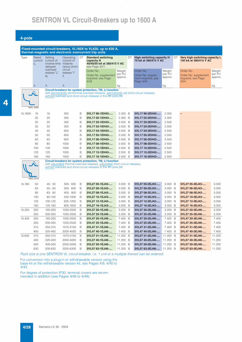
Siemens LV 30 · 20044/28
SENTRON VL Circuit-Breakers up to 1600 A
4-pole
4
Pack size is one SENTRON VL circuit-breaker, i.e. 1 unit or a multiple thereof can be ordered.
For conversion into a plug-in or withdrawable version using the base kit or the withdrawable version kit, see Pages 4/9, 4/40 to 4/43.
For degree of protection IP30, terminal covers are recom-mended in addition (see Pages 4/46 to 4/49).
Fixed-mounted circuit-breakers, VL160X to VL630, up to 630 A, thermal-magnetic and electronic overcurrent trip units
Type Ratedcurrent In
Settingcurrent of inverse-timedelayedoverloadrelease "L"IR
Operatingcurrent of instanta-neous short-circuit release "I"Ii
DT Standard switching capacity N 40/45/50 kA at 380/415 V ACsee Page 4/21.
DT High switching capacity H 70 kA at 380/415 V AC
DT Very high switching capacity L 100 kA at 380/415 V AC
Order No. Weight per PU approx.
Order No. Weight per PU approx.
Order No. Weight per PU approx.
Order No. supplement required, see Page 4/34
Order No. supple-ment required, see Page 4/34
Order No. supplement required, see Page 4/34
A A A kg kg kg
Circuit-breakers for system protection, TM, LI functionwith permanently set thermal overload releases, permanently set short-circuit releases, without overload and short-circuit releases in the 4th pole (N)
VL160X 16 16 300 B 3VL17 96-1EH43-.... 2.300 B 3VL17 96-2EH43-.... 2.300 –
20 20 300 B 3VL17 02-1EH43-.... 2.300 B 3VL17 02-2EH43-.... 2.300
25 25 300 B 3VL17 25-1EH43-.... 2.500 B 3VL17 25-2EH43-.... 2.500
32 32 300 B 3VL17 03-1EH43-.... 2.500 B 3VL17 03-2EH43-.... 2.500
40 40 600 B 3VL17 04-1EH43-.... 2.500 B 3VL17 04-2EH43-.... 2.500
50 50 600 B 3VL17 05-1EH43-.... 2.500 B 3VL17 05-2EH43-.... 2.500
63 63 600 B 3VL17 06-1EH43-.... 2.500 B 3VL17 06-2EH43-.... 2.500
80 80 1000 B 3VL17 08-1EH43-.... 2.500 B 3VL17 08-2EH43-.... 2.500
100 100 1000 B 3VL17 10-1EH43-.... 2.500 B 3VL17 10-2EH43-.... 2.500
125 125 1000 B 3VL17 12-1EH43-.... 2.500 B 3VL17 12-2EH43-.... 2.500
160 160 1500 B 3VL17 16-1EH43-.... 2.500 B 3VL17 16-2EH43-.... 2.500
Circuit-breakers for system protection, TM, LI functionwith adjustable thermal overload releases, adjustable short-circuit releases, without overload and short-circuit releases in the 4th pole (N)
VL160 50 40- 50 300- 600 B 3VL27 05-1EJ43-.... 3.000 B 3VL27 05-2EJ43-.... 3.000 B 3VL27 05-3EJ43-.... 3.000
63 50- 63 300- 600 B 3VL27 06-1EJ43-.... 3.000 B 3VL27 06-2EJ43-.... 3.000 B 3VL27 06-3EJ43-.... 3.000
80 63- 80 400- 800 B 3VL27 08-1EJ43-.... 3.000 B 3VL27 08-2EJ43-.... 3.000 B 3VL27 08-3EJ43-.... 3.000
100 80-100 500-1000 B 3VL27 10-1EJ43-.... 3.000 B 3VL27 10-2EJ43-.... 3.000 B 3VL27 10-3EJ43-.... 3.000
125 100-125 625-1250 B 3VL27 12-1EJ43-.... 3.000 B 3VL27 12-2EJ43-.... 3.000 B 3VL27 12-3EJ43-.... 3.000
160 125-160 800-1600 B 3VL27 16-1EJ43-.... 3.000 B 3VL27 16-2EJ43-.... 3.000 B 3VL27 16-3EJ43-.... 3.000
VL250 200 160-200 1000-2000 B 3VL37 20-1EJ46-.... 3.200 B 3VL37 20-2EJ46-.... 3.200 B 3VL37 20-3EJ46-.... 3.200
250 200-250 1250-2500 B 3VL37 25-1EJ46-.... 3.200 B 3VL37 25-2EJ46-.... 3.200 B 3VL37 25-3EJ46-.... 3.200
VL400 200 160-200 1000-2000 B 3VL47 20-1EJ46-.... 7.400 B 3VL47 20-2EJ46-.... 7.400 B 3VL47 20-3EJ46-.... 7.400
250 200-250 1250-2500 B 3VL47 25-1EJ46-.... 7.400 B 3VL47 25-2EJ46-.... 7.400 B 3VL47 25-3EJ46-.... 7.400
315 250-315 1575-3150 B 3VL47 31-1EJ46-.... 7.400 B 3VL47 31-2EJ46-.... 7.400 B 3VL47 31-3EJ46-.... 7.400
400 320-400 2000-4000 B 3VL47 40-1EJ46-.... 7.400 B 3VL47 40-2EJ46-.... 7.400 B 3VL47 40-3EJ46-.... 7.400
VL630 315 250-315 1575-3150 B 3VL57 31-1EJ46-.... 11.200 B 3VL57 31-2EJ46-.... 11.200 B 3VL57 31-3EJ46-.... 11.200
400 320-400 2000-4000 B 3VL57 40-1EJ46-.... 11.200 B 3VL57 40-2EJ46-.... 11.200 B 3VL57 40-3EJ46-.... 11.200
500 400-500 2500-5000 B 3VL57 50-1EJ46-.... 11.200 B 3VL57 50-2EJ46-.... 11.200 B 3VL57 50-3EJ46-.... 11.200
630 500-630 3250-6300 B 3VL57 63-1EJ46-.... 11.200 B 3VL57 63-2EJ46-.... 11.200 B 3VL57 63-3EJ46-.... 11.200
NSE0_00695
NSE0_00704
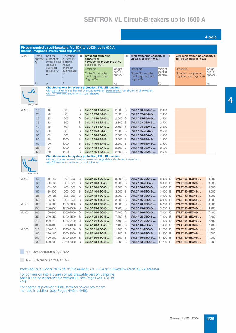
Siemens LV 30 · 2004 4/29
SENTRON VL Circuit-Breakers up to 1600 A
4-pole
4
N = 100 % protection for In ≤ 100 A
N = 60 % protection for In ≥ 125 A
Pack size is one SENTRON VL circuit-breaker, i.e. 1 unit or a multiple thereof can be ordered.
For conversion into a plug-in or withdrawable version using the base kit or the withdrawable version kit, see Pages 4/9, 4/40 to 4/43.
For degree of protection IP30, terminal covers are recom-mended in addition (see Pages 4/46 to 4/49).
Fixed-mounted circuit-breakers, VL160X to VL630, up to 630 A, thermal-magnetic overcurrent trip units
Type Ratedcurrent In
Settingcurrent of inverse-timedelayed overloadrelease "L"IR
Operating current of instanta-neousshort-cir-cuit release "I"Ii
DT Standard switching capacity N 40/45/50 kA at 380/415 V ACsee Page 4/21.
DT High switching capacity H 70 kA at 380/415 V AC
DT Very high switching capacity L 100 kA at 380/415 V AC
Order No. Weight per PU approx.
Order No. Weight per PU approx.
Order No. Weight per PU approx.
Order No. supple-ment required, see Page 4/34
Order No. supple-ment required, see Page 4/34
Order No. supplement required, see Page 4/34
A A A kg kg kg
Circuit-breakers for system protection, TM, LIN functionwith permanently set thermal overload releases, permanently set short-circuit releases, with "N" overload and short-circuit releases
VL160X 16 16 300 B 3VL17 96-1EA43-.... 2.300 B 3VL17 96-2EA43-.... 2.300 –
20 20 300 B 3VL17 02-1EA43-.... 2.300 B 3VL17 02-2EA43-.... 2.300
25 25 300 B 3VL17 25-1EA43-.... 2.500 B 3VL17 25-2EA43-.... 2.500
32 32 300 B 3VL17 03-1EA43-.... 2.500 B 3VL17 03-2EA43-.... 2.500
40 40 600 B 3VL17 04-1EA43-.... 2.500 B 3VL17 04-2EA43-.... 2.500
50 50 600 B 3VL17 05-1EA43-.... 2.500 B 3VL17 05-2EA43-.... 2.500
63 63 600 B 3VL17 06-1EA43-.... 2.500 B 3VL17 06-2EA43-.... 2.500
80 80 1000 B 3VL17 08-1EA43-.... 2.500 B 3VL17 08-2EA43-.... 2.500
100 100 1000 B 3VL17 10-1EA43-.... 2.500 B 3VL17 10-2EA43-.... 2.500
125 125 1000 B 3VL17 12-1EA43-.... 2.500 B 3VL17 12-2EA43-.... 2.500
160 160 1500 B 3VL17 16-1EA43-.... 2.500 B 3VL17 16-2EA43-.... 2.500
Circuit-breakers for system protection, TM, LIN functionwith adjustable thermal overload releases, adjustable short-circuit releases, with "N" overload and short-circuit releases
VL160 50 40- 50 300- 600 B 3VL27 05-1EC43-.... 3.000 B 3VL27 05-2EC43-.... 3.000 B 3VL27 05-3EC43-.... 3.000
63 50- 63 300- 600 B 3VL27 06-1EC43-.... 3.000 B 3VL27 06-2EC43-.... 3.000 B 3VL27 06-3EC43-.... 3.000
80 63- 80 400- 800 B 3VL27 08-1EC43-.... 3.000 B 3VL27 08-2EC43-.... 3.000 B 3VL27 08-3EC43-.... 3.000
100 80-100 500-1000 B 3VL27 10-1EC43-.... 3.000 B 3VL27 10-2EC43-.... 3.000 B 3VL27 10-3EC43-.... 3.000
125 100-125 625-1250 B 3VL27 12-1EC43-.... 3.000 B 3VL27 12-2EC43-.... 3.000 B 3VL27 12-3EC43-.... 3.000
160 125-160 800-1600 B 3VL27 16-1EC43-.... 3.000 B 3VL27 16-2EC43-.... 3.000 B 3VL27 16-3EC43-.... 3.000
VL250 200 160-200 1000-2000 B 3VL37 20-1EC46-.... 3.200 B 3VL37 20-2EC46-.... 3.200 B 3VL37 20-3EC46-.... 3.200
250 200-250 1200-2500 B 3VL37 25-1EC46-.... 3.200 B 3VL37 25-2EC46-.... 3.200 B 3VL37 25-3EC46-.... 3.200
VL400 200 160-200 1000-2000 B 3VL47 20-1EC46-.... 7.400 B 3VL47 20-2EC46-.... 7.400 B 3VL47 20-3EC46-.... 7.400
250 200-250 1200-2500 B 3VL47 25-1EC46-.... 7.400 B 3VL47 25-2EC46-.... 7.400 B 3VL47 25-3EC46-.... 7.400
315 250-315 1575-3150 B 3VL47 31-1EC46-.... 7.400 B 3VL47 31-2EC46-.... 7.400 B 3VL47 31-3EC46-.... 7.400
400 320-400 2000-4000 B 3VL47 40-1EC46-.... 7.400 B 3VL47 40-2EC46-.... 7.400 B 3VL47 40-3EC46-.... 7.400
VL630 315 250-315 1575-3150 B 3VL57 31-1EC46-.... 11.200 B 3VL57 31-2EC46-.... 11.200 B 3VL57 31-3EC46-.... 11.200
400 320-400 2000-4000 B 3VL57 40-1EC46-.... 11.200 B 3VL57 40-2EC46-.... 11.200 B 3VL57 40-3EC46-.... 11.200
500 400-500 2500-5000 B 3VL57 50-1EC46-.... 11.200 B 3VL57 50-2EC46-.... 11.200 B 3VL57 50-3EC46-.... 11.200
630 500-630 3250-6300 B 3VL57 63-1EC46-.... 11.200 B 3VL57 63-2EC46-.... 11.200 B 3VL57 63-3EC46-.... 11.200
NSE0_00695
NSE0_00704
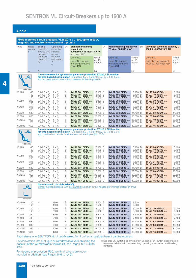
Siemens LV 30 · 20044/30
SENTRON VL Circuit-Breakers up to 1600 A
4-pole
4
Pack size is one SENTRON VL circuit-breaker, i.e. 1 unit or a multiple thereof can be ordered.
For conversion into a plug-in or withdrawable version using the base kit or the withdrawable version kit, see Pages 4/9, 4/40 to 4/43.
For degree of protection IP30, terminal covers are recom-mended in addition (see Pages 4/46 to 4/49).
1) See also 3K. switch disconnectors in Section 6. 3K. switch disconnectors are also available with rear-mounting operating mechanism and leading contacts.
Fixed-mounted circuit-breakers, VL160X to VL1600, up to 1600 A, magnetic and electronic overcurrent trip units
Type Ratedcurrent In
Setting current of inverse-time delayedoverload release "L" IR
Operating current of instanta-neousshort-cir-cuit release "I"Ii
DT Standard switching capacity N 40/45/50 kA at 380/415 V ACsee Page 4/21.
DT High switching capacity H 70 kA at 380/415 V AC
DT Very high switching capacity L 100 kA at 380/415 V AC
Order No. Weight per PU approx.
Order No. Weight per PU approx.
Order No. Weight per PU approx.
Order No. supple-ment required, see Page 4/34
Order No. supple-ment required, see Page 4/34
Order No. supplement required, see Page 4/34
A A A kg kg kg
Circuit-breakers for system and generator protection, ETU20, LSI functionfor time-based discrimination (S function: Isd = 1.5 to 10 × IR, tsd = 0 to 0.5 s), without overload and short-circuit releases in the 4th pole (N)
VL160 63 0.4-1.0 × In 11 × In B 3VL27 06-1BE43-.... 3.100 B 3VL27 06-2BE43-.... 3.100 B 3VL27 06-3BE43-.... 3.100100 0.4-1.0 × In 11 × In B 3VL27 10-1BE43-.... 3.100 B 3VL27 10-2BE43-.... 3.100 B 3VL27 10-3BE43-.... 3.100160 0.4-1.0 × In 11 × In B 3VL27 16-1BE43-.... 3.100 B 3VL27 16-2BE43-.... 3.100 B 3VL27 16-3BE43-.... 3.100
VL250 200 0.4-1.0 × In 11 × In B 3VL37 20-1BE46-.... 3.300 B 3VL37 20-2BE46-.... 3.300 B 3VL37 20-3BE46-.... 3.300250 0.4-1.0 × In 11 × In B 3VL37 25-1BE46-.... 3.300 B 3VL37 25-2BE46-.... 3.300 B 3VL37 25-3BE46-.... 3.300
VL400 315 0.4-1.0 × In 11 × In B 3VL47 31-1BE46-.... 7.600 B 3VL47 31-2BE46-.... 7.600 B 3VL47 31-3BE46-.... 7.600400 0.4-1.0 × In 11 × In B 3VL47 40-1BE46-.... 7.600 B 3VL47 40-2BE46-.... 7.600 B 3VL47 40-3BE46-.... 7.600
VL630 630 0.4-1.0 × In 10 × In B 3VL57 63-1BE46-.... 11.700 B 3VL57 63-2BE46-.... 11.700 B 3VL57 63-3BE46-.... 11.700
VL800 800 0.4-1.0 × In 8 × In B 3VL67 80-1BE46-.... 20.500 B 3VL67 80-2BE46-.... 20.500 B 3VL67 80-3BE46-.... 20.500
VL1250 1000 0.4-1.0 × In 11 × In B 3VL77 10-1BE46-.... 33.500 B 3VL77 10-2BE46-.... 33.500 B 3VL77 10-3BE46-.... 33.5001250 0.4-1.0 × In 10 × In B 3VL77 12-1BE46-.... 33.500 B 3VL77 12-2BE46-.... 33.500 B 3VL77 12-3BE46-.... 33.500
VL1600 1600 0.4-1.0 × In 9 × In B 3VL87 16-1BE40-.... 40.800 B 3VL87 16-2BE40-.... 40.800 B 3VL87 16-3BE40-.... 40.800
Circuit-breakers for system and generator protection, ETU20, LSIN functionfor time-based discrimination (S function: Isd = 1.5 to 10 × IR, tsd = 0 to 0.5 s), with overload and short-circuit releases in the 4th pole (N): 50 %
VL160 63 0.4-1.0 × In 11 × In B 3VL27 06-1BF43-.... 3.100 B 3VL27 06-2BF43-.... 3.100 B 3VL27 06-3BF43-.... 3.100100 0.4-1.0 × In 11 × In B 3VL27 10-1BF43-.... 3.100 B 3VL27 10-2BF43-.... 3.100 B 3VL27 10-3BF43-.... 3.100160 0.4-1.0 × In 11 × In B 3VL27 16-1BF43-.... 3.100 B 3VL27 16-2BF43-.... 3.100 B 3VL27 16-3BF43-.... 3.100
VL250 200 0.4-1.0 × In 11 × In B 3VL37 20-1BF46-.... 3.300 B 3VL37 20-2BF46-.... 3.300 B 3VL37 20-3BF46-.... 3.300250 0.4-1.0 × In 11 × In B 3VL37 25-1BF46-.... 3.300 B 3VL37 25-2BF46-.... 3.300 B 3VL37 25-3BF46-.... 3.300
VL400 315 0.4-1.0 × In 11 × In B 3VL47 31-1BF46-.... 7.600 B 3VL47 31-2BF46-.... 7.600 B 3VL47 31-3BF46-.... 7.600400 0.4-1.0 × In 11 × In B 3VL47 40-1BF46-.... 7.600 B 3VL47 40-2BF46-.... 7.600 B 3VL47 40-3BF46-.... 7.600
VL630 630 0.4-1.0 × In 10 × In B 3VL57 63-1BF46-.... 11.700 B 3VL57 63-2BF46-.... 11.700 B 3VL57 63-3BF46-.... 11.700
VL800 800 0.4-1.0 × In 8 × In B 3VL67 80-1BF46-.... 20.500 B 3VL67 80-2BF46-.... 20.500 B 3VL67 80-3BF46-.... 20.500
VL1250 1000 0.4-1.0 × In 11 × In B 3VL77 10-1BF46-.... 33.500 B 3VL77 10-2BF46-.... 33.500 B 3VL77 10-3BF46-.... 33.5001250 0.4-1.0 × In 10 × In B 3VL77 12-1BF46-.... 33.500 B 3VL77 12-2BF46-.... 33.500 B 3VL77 12-3BF46.... 33.500
VL1600 1600 0.4-1.0 × In 9 × In B 3VL87 16-1BF40-.... 40.800 B 3VL87 16-2BF40-.... 40.800 B 3VL87 16-3BF40-.... 40.800
Non-automatic circuit-breakers1)without overload release, with permanently set short-circuit release (for intrinsic protection only)
VL160X 100 – 1800 B 3VL17 10-1EE43-.... 2.500 B 3VL17 10-2EE43-.... 2.500 –160 – 1800 B 3VL17 16-1EE43-.... 2.500 B 3VL17 16-2EE43-.... 2.500 –
VL160 100 – 2500 B 3VL27 10-1EE43-.... 3.000 B 3VL27 10-2EE43-.... 3.000 B 3VL27 10-3EE43-.... 3.000160 – 2500 B 3VL27 16-1EE43-.... 3.000 B 3VL27 16-2EE43-.... 3.000 B 3VL27 16-3EE43-.... 3.000
VL250 250 – 3500 B 3VL37 25-1EE46-.... 3.200 B 3VL37 25-2EE46-.... 3.200 B 3VL37 25-3EE46-.... 3.200
VL400 400 – 5500 B 3VL47 40-1EE46-.... 7.400 B 3VL47 40-2EE46-.... 7.400 B 3VL47 40-3EE46-.... 7.400
VL630 630 – 6300 B 3VL57 63-1EE46-.... 11.200 B 3VL57 63-2EE46-.... 11.200 B 3VL57 63-3EE46-.... 11.200
VL800 800 – 6300 B 3VL67 80-1EE46-.... 19.900 B 3VL67 80-2EE46-.... 19.900 B 3VL67 80-3EE46-.... 19.900
VL1250 1250 – 12000 B 3VL77 12-1EE46-.... 31.000 B 3VL77 12-2EE46-.... 31.000 B 3VL77 12-3EE46-.... 31.000
VL1600 1600 – 14400 B 3VL87 16-1EE40-.... 38.300 B 3VL87 16-2EE40-.... 38.300 B 3VL87 16-3EE40-.... 38.300
NSE0_00922
NSE0_00922
NSE0_00708
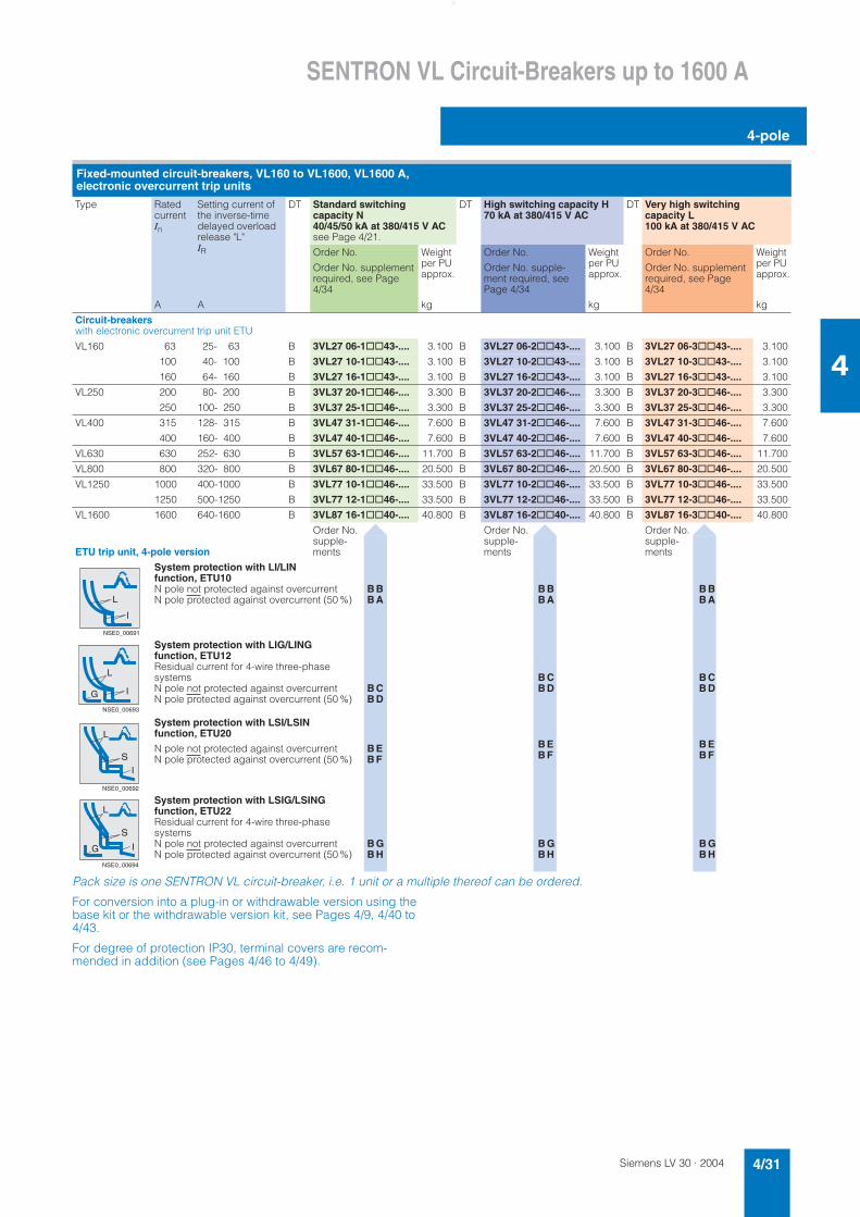
Siemens LV 30 · 2004 4/31
SENTRON VL Circuit-Breakers up to 1600 A
4-pole
4
Pack size is one SENTRON VL circuit-breaker, i.e. 1 unit or a multiple thereof can be ordered.
For conversion into a plug-in or withdrawable version using the base kit or the withdrawable version kit, see Pages 4/9, 4/40 to 4/43.
For degree of protection IP30, terminal covers are recom-mended in addition (see Pages 4/46 to 4/49).
Fixed-mounted circuit-breakers, VL160 to VL1600, VL1600 A, electronic overcurrent trip units
Type RatedcurrentIn
Setting current of the inverse-time delayed overload release "L" IR
DT Standard switching capacity N 40/45/50 kA at 380/415 V ACsee Page 4/21.
DT High switching capacity H 70 kA at 380/415 V AC
DT Very high switching capacity L 100 kA at 380/415 V AC
Order No. Weight per PU approx.
Order No. Weight per PU approx.
Order No. Weight per PU approx.
Order No. supplement required, see Page 4/34
Order No. supple-ment required, see Page 4/34
Order No. supplement required, see Page 4/34
A A kg kg kg
Circuit-breakerswith electronic overcurrent trip unit ETU
VL160 63 25- 63 B 3VL27 06-1@@43-.... 3.100 B 3VL27 06-2@@43-.... 3.100 B 3VL27 06-3@@43-.... 3.100
100 40- 100 B 3VL27 10-1@@43-.... 3.100 B 3VL27 10-2@@43-.... 3.100 B 3VL27 10-3@@43-.... 3.100
160 64- 160 B 3VL27 16-1@@43-.... 3.100 B 3VL27 16-2@@43-.... 3.100 B 3VL27 16-3@@43-.... 3.100
VL250 200 80- 200 B 3VL37 20-1@@46-.... 3.300 B 3VL37 20-2@@46-.... 3.300 B 3VL37 20-3@@46-.... 3.300
250 100- 250 B 3VL37 25-1@@46-.... 3.300 B 3VL37 25-2@@46-.... 3.300 B 3VL37 25-3@@46-.... 3.300
VL400 315 128- 315 B 3VL47 31-1@@46-.... 7.600 B 3VL47 31-2@@46-.... 7.600 B 3VL47 31-3@@46-.... 7.600
400 160- 400 B 3VL47 40-1@@46-.... 7.600 B 3VL47 40-2@@46-.... 7.600 B 3VL47 40-3@@46-.... 7.600
VL630 630 252- 630 B 3VL57 63-1@@46-.... 11.700 B 3VL57 63-2@@46-.... 11.700 B 3VL57 63-3@@46-.... 11.700
VL800 800 320- 800 B 3VL67 80-1@@46-.... 20.500 B 3VL67 80-2@@46-.... 20.500 B 3VL67 80-3@@46-.... 20.500
VL1250 1000 400-1000 B 3VL77 10-1@@46-.... 33.500 B 3VL77 10-2@@46-.... 33.500 B 3VL77 10-3@@46-.... 33.500
1250 500-1250 B 3VL77 12-1@@46-.... 33.500 B 3VL77 12-2@@46-.... 33.500 B 3VL77 12-3@@46-.... 33.500
VL1600 1600 640-1600 B 3VL87 16-1@@40-.... 40.800 B 3VL87 16-2@@40-.... 40.800 B 3VL87 16-3@@40-.... 40.800
ETU trip unit, 4-pole version
Order No. supple-ments
Order No. supple-ments
Order No. supple-ments
System protection with LI/LIN function, ETU10N pole not protected against overcurrent B BN pole protected against overcurrent (50 %) B A
B BB A
B BB A
System protection with LIG/LING function, ETU12Residual current for 4-wire three-phase systemsN pole not protected against overcurrent B CN pole protected against overcurrent (50 %) B D
B CB D
B CB D
System protection with LSI/LSIN function, ETU20
N pole not protected against overcurrent B EN pole protected against overcurrent (50 %) B F
B EB F
B EB F
System protection with LSIG/LSING function, ETU22Residual current for 4-wire three-phase systemsN pole not protected against overcurrent B GN pole protected against overcurrent (50 %) B H
B GB H
B GB H
L
I
NSE0_00691
L
IG
NSE0_00693
L
S
I
NSE0_00692
L
S
IG
NSE0_00694
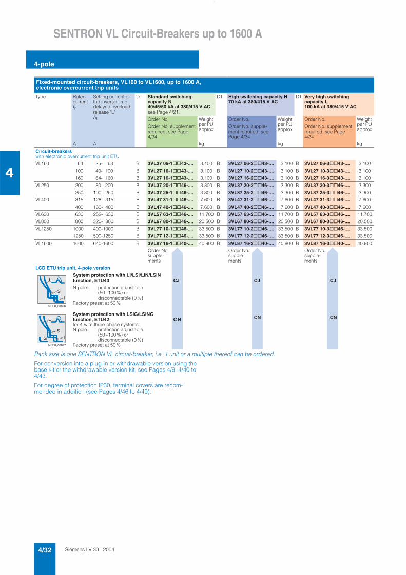
Siemens LV 30 · 20044/32
SENTRON VL Circuit-Breakers up to 1600 A
4-pole
4
Pack size is one SENTRON VL circuit-breaker, i.e. 1 unit or a multiple thereof can be ordered.
For conversion into a plug-in or withdrawable version using the base kit or the withdrawable version kit, see Pages 4/9, 4/40 to 4/43.
For degree of protection IP30, terminal covers are recom-mended in addition (see Pages 4/46 to 4/49).
Fixed-mounted circuit-breakers, VL160 to VL1600, up to 1600 A, electronic overcurrent trip units
Type RatedcurrentIn
Setting current of the inverse-time delayed overload release "L" IR
DT Standard switching capacity N 40/45/50 kA at 380/415 V ACsee Page 4/21.
DT High switching capacity H 70 kA at 380/415 V AC
DT Very high switching capacity L 100 kA at 380/415 V AC
Order No. Weight per PU approx.
Order No. Weight per PU approx.
Order No. Weight per PU approx.
Order No. supplement required, see Page 4/34
Order No. supple-ment required, see Page 4/34
Order No. supplement required, see Page 4/34
A A kg kg kg
Circuit-breakerswith electronic overcurrent trip unit ETU
VL160 63 25- 63 B 3VL27 06-1@@43-.... 3.100 B 3VL27 06-2@@43-.... 3.100 B 3VL27 06-3@@43-.... 3.100
100 40- 100 B 3VL27 10-1@@43-.... 3.100 B 3VL27 10-2@@43-.... 3.100 B 3VL27 10-3@@43-.... 3.100
160 64- 160 B 3VL27 16-1@@43-.... 3.100 B 3VL27 16-2@@43-.... 3.100 B 3VL27 16-3@@43-.... 3.100
VL250 200 80- 200 B 3VL37 20-1@@46-.... 3.300 B 3VL37 20-2@@46-.... 3.300 B 3VL37 20-3@@46-.... 3.300
250 100- 250 B 3VL37 25-1@@46-.... 3.300 B 3VL37 25-2@@46-.... 3.300 B 3VL37 25-3@@46-.... 3.300
VL400 315 128- 315 B 3VL47 31-1@@46-.... 7.600 B 3VL47 31-2@@46-.... 7.600 B 3VL47 31-3@@46-.... 7.600
400 160- 400 B 3VL47 40-1@@46-.... 7.600 B 3VL47 40-2@@46-.... 7.600 B 3VL47 40-3@@46-.... 7.600
VL630 630 252- 630 B 3VL57 63-1@@46-.... 11.700 B 3VL57 63-2@@46-.... 11.700 B 3VL57 63-3@@46-.... 11.700
VL800 800 320- 800 B 3VL67 80-1@@46-.... 20.500 B 3VL67 80-2@@46-.... 20.500 B 3VL67 80-3@@46-.... 20.500
VL1250 1000 400-1000 B 3VL77 10-1@@46-.... 33.500 B 3VL77 10-2@@46-.... 33.500 B 3VL77 10-3@@46-.... 33.500
1250 500-1250 B 3VL77 12-1@@46-.... 33.500 B 3VL77 12-2@@46-.... 33.500 B 3VL77 12-3@@46-.... 33.500
VL1600 1600 640-1600 B 3VL87 16-1@@40-.... 40.800 B 3VL87 16-2@@40-.... 40.800 B 3VL87 16-3@@40-.... 40.800
Order No. supple-ments
Order No. supple-ments
Order No. supple-ments
LCD ETU trip unit, 4-pole version
System protection with LI/LSI/LIN/LSIN function, ETU40 CJ CJ CJ
N pole: protection adjustable (50 –100 %) or disconnectable (0 %)
Factory preset at 50 %
System protection with LSIG/LSING function, ETU42 C Nfor 4-wire three-phase systemsN pole: protection adjustable
(50 –100 %) or disconnectable (0 %)
Factory preset at 50 %
CN CN
L
S
I
NSE0_00696
L
S
IG
NSE0_00697
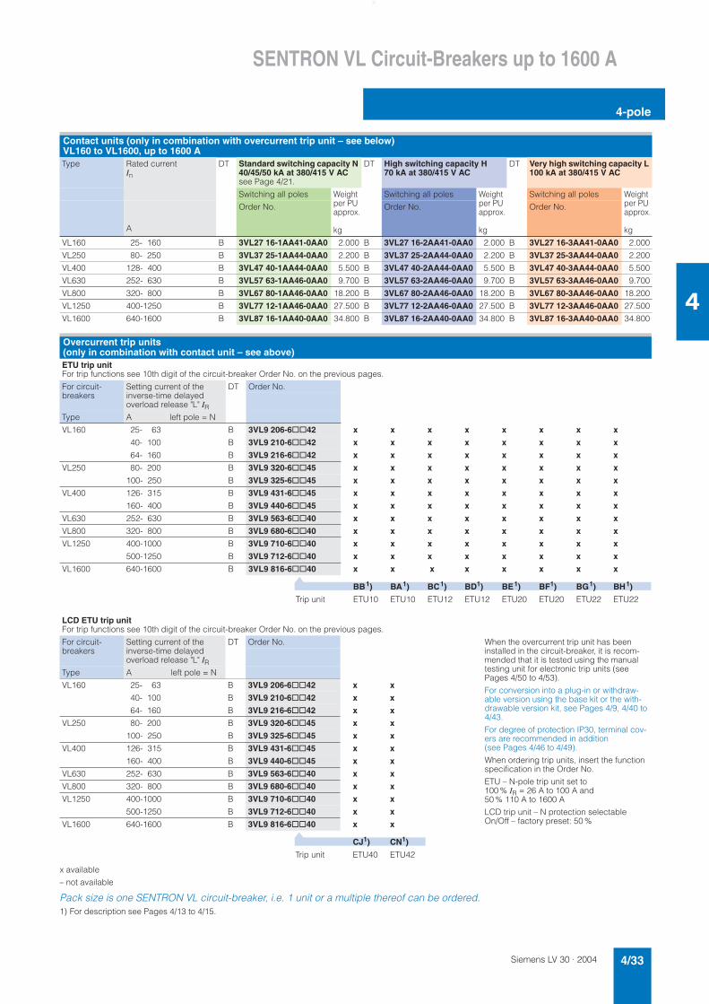
Siemens LV 30 · 2004 4/33
SENTRON VL Circuit-Breakers up to 1600 A
4-pole
4
x available
– not available
Pack size is one SENTRON VL circuit-breaker, i.e. 1 unit or a multiple thereof can be ordered.1) For description see Pages 4/13 to 4/15.
Contact units (only in combination with overcurrent trip unit – see below) VL160 to VL1600, up to 1600 AType Rated current
InDT Standard switching capacity N
40/45/50 kA at 380/415 V ACsee Page 4/21.
DT High switching capacity H 70 kA at 380/415 V AC
DT Very high switching capacity L 100 kA at 380/415 V AC
Switching all poles Weight per PU approx.
kg
Switching all poles Weight per PU approx.
kg
Switching all poles Weight per PU approx.
kgA
Order No. Order No. Order No.
VL160 25- 160 B 3VL27 16-1AA41-0AA0 2.000 B 3VL27 16-2AA41-0AA0 2.000 B 3VL27 16-3AA41-0AA0 2.000
VL250 80- 250 B 3VL37 25-1AA44-0AA0 2.200 B 3VL37 25-2AA44-0AA0 2.200 B 3VL37 25-3AA44-0AA0 2.200
VL400 128- 400 B 3VL47 40-1AA44-0AA0 5.500 B 3VL47 40-2AA44-0AA0 5.500 B 3VL47 40-3AA44-0AA0 5.500
VL630 252- 630 B 3VL57 63-1AA46-0AA0 9.700 B 3VL57 63-2AA46-0AA0 9.700 B 3VL57 63-3AA46-0AA0 9.700
VL800 320- 800 B 3VL67 80-1AA46-0AA0 18.200 B 3VL67 80-2AA46-0AA0 18.200 B 3VL67 80-3AA46-0AA0 18.200
VL1250 400-1250 B 3VL77 12-1AA46-0AA0 27.500 B 3VL77 12-2AA46-0AA0 27.500 B 3VL77 12-3AA46-0AA0 27.500
VL1600 640-1600 B 3VL87 16-1AA40-0AA0 34.800 B 3VL87 16-2AA40-0AA0 34.800 B 3VL87 16-3AA40-0AA0 34.800
Overcurrent trip units (only in combination with contact unit – see above)ETU trip unitFor trip functions see 10th digit of the circuit-breaker Order No. on the previous pages.
For circuit-breakers
Setting current of the inverse-time delayed overload release "L" IR
DT Order No.
Type A left pole = N
VL160 25- 63 B 3VL9 206-6@@42 x x x x x x x x
40- 100 B 3VL9 210-6@@42 x x x x x x x x
64- 160 B 3VL9 216-6@@42 x x x x x x x x
VL250 80- 200 B 3VL9 320-6@@45 x x x x x x x x
100- 250 B 3VL9 325-6@@45 x x x x x x x x
VL400 126- 315 B 3VL9 431-6@@45 x x x x x x x x
160- 400 B 3VL9 440-6@@45 x x x x x x x x
VL630 252- 630 B 3VL9 563-6@@40 x x x x x x x x
VL800 320- 800 B 3VL9 680-6@@40 x x x x x x x x
VL1250 400-1000 B 3VL9 710-6@@40 x x x x x x x x
500-1250 B 3VL9 712-6@@40 x x x x x x x x
VL1600 640-1600 B 3VL9 816-6@@40 x x x x x x x x
BB1) BA1) BC1) BD1) BE1) BF1) BG1) BH1)
Trip unit ETU10 ETU10 ETU12 ETU12 ETU20 ETU20 ETU22 ETU22
▼
LCD ETU trip unitFor trip functions see 10th digit of the circuit-breaker Order No. on the previous pages.
For circuit-breakers
Setting current of the inverse-time delayed overload release "L" IR
DT Order No. When the overcurrent trip unit has been installed in the circuit-breaker, it is recom-mended that it is tested using the manual testing unit for electronic trip units (see Pages 4/50 to 4/53).
For conversion into a plug-in or withdraw-able version using the base kit or the with-drawable version kit, see Pages 4/9, 4/40 to 4/43.
For degree of protection IP30, terminal cov-ers are recommended in addition (see Pages 4/46 to 4/49).
When ordering trip units, insert the function specification in the Order No.
ETU – N-pole trip unit set to 100 % IR = 26 A to 100 A and 50 % 110 A to 1600 A
LCD trip unit – N protection selectable On/Off – factory preset: 50 %
Type A left pole = N
VL160 25- 63 B 3VL9 206-6@@42 x x
40- 100 B 3VL9 210-6@@42 x x
64- 160 B 3VL9 216-6@@42 x x
VL250 80- 200 B 3VL9 320-6@@45 x x
100- 250 B 3VL9 325-6@@45 x x
VL400 126- 315 B 3VL9 431-6@@45 x x
160- 400 B 3VL9 440-6@@45 x x
VL630 252- 630 B 3VL9 563-6@@40 x x
VL800 320- 800 B 3VL9 680-6@@40 x x
VL1250 400-1000 B 3VL9 710-6@@40 x x
500-1250 B 3VL9 712-6@@40 x x
VL1600 640-1600 B 3VL9 816-6@@40 x x
CJ1) CN1)
Trip unit ETU40 ETU42
▼
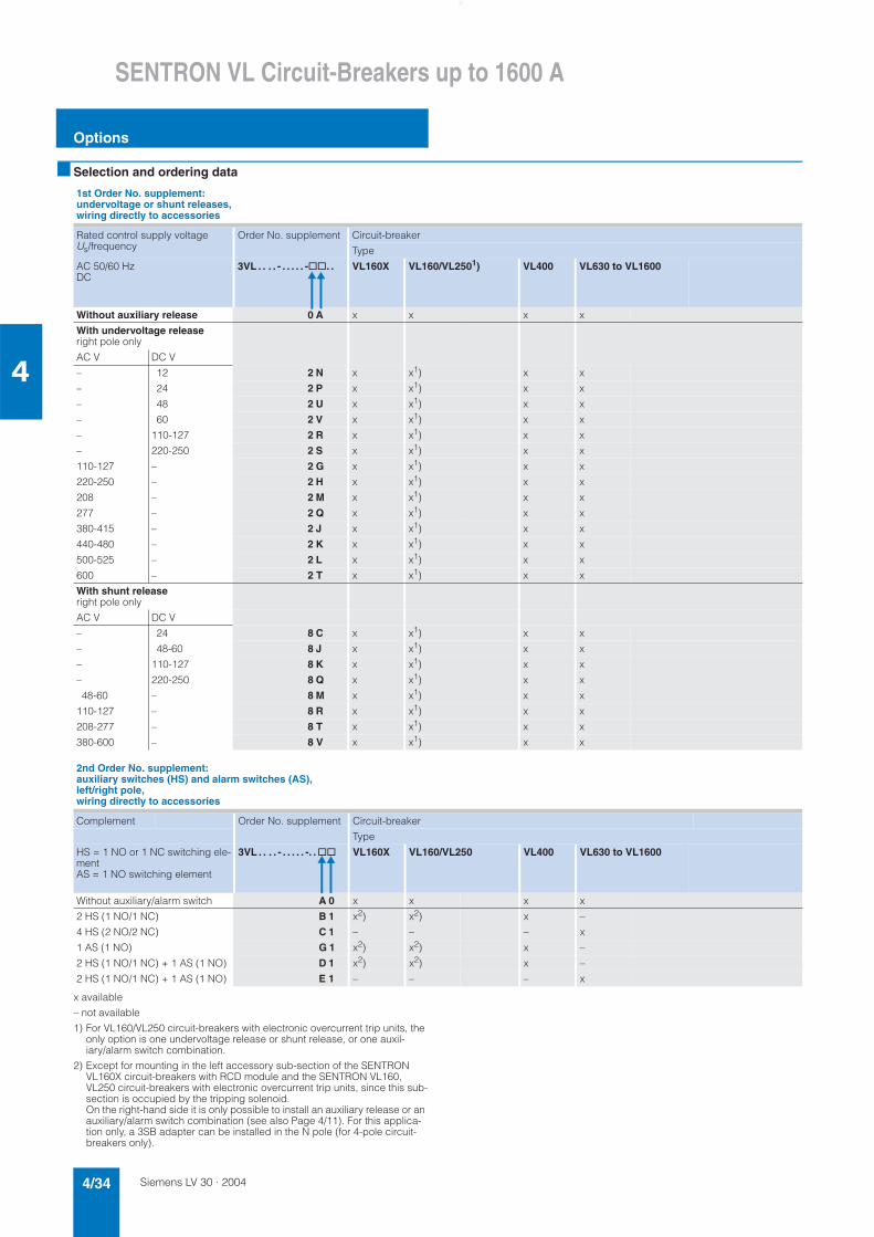
Siemens LV 30 · 20044/34
SENTRON VL Circuit-Breakers up to 1600 A
Options
4
■ Selection and ordering data
x available
– not available
1) For VL160/VL250 circuit-breakers with electronic overcurrent trip units, the only option is one undervoltage release or shunt release, or one auxil-iary/alarm switch combination.
2) Except for mounting in the left accessory sub-section of the SENTRON VL160X circuit-breakers with RCD module and the SENTRON VL160, VL250 circuit-breakers with electronic overcurrent trip units, since this sub-section is occupied by the tripping solenoid. On the right-hand side it is only possible to install an auxiliary release or an auxiliary/alarm switch combination (see also Page 4/11). For this applica-tion only, a 3SB adapter can be installed in the N pole (for 4-pole circuit-breakers only).
1st Order No. supplement: undervoltage or shunt releases, wiring directly to accessories
Rated control supply voltage Us/frequency
Order No. supplement Circuit-breaker
Type
AC 50/60 HzDC
3VL . . . . - . . . . . -@@. . VL160X VL160/VL2501) VL400 VL630 to VL1600
Without auxiliary release 0 A x x x x
With undervoltage release right pole only
AC V DC V
– 12 2 N x x1) x x
– 24 2 P x x1) x x
– 48 2 U x x1) x x
– 60 2 V x x1) x x
– 110-127 2 R x x1) x x
– 220-250 2 S x x1) x x
110-127 – 2 G x x1) x x
220-250 – 2 H x x1) x x
208 – 2 M x x1) x x
277 – 2 Q x x1) x x
380-415 – 2 J x x1) x x
440-480 – 2 K x x1) x x
500-525 – 2 L x x1) x x
600 – 2 T x x1) x x
With shunt release right pole only
AC V DC V
– 24 8 C x x1) x x
– 48-60 8 J x x1) x x
– 110-127 8 K x x1) x x
– 220-250 8 Q x x1) x x
48-60 – 8 M x x1) x x
110-127 – 8 R x x1) x x
208-277 – 8 T x x1) x x
380-600 – 8 V x x1) x x
2nd Order No. supplement: auxiliary switches (HS) and alarm switches (AS), left/right pole, wiring directly to accessories
Complement Order No. supplement Circuit-breaker
Type
HS = 1 NO or 1 NC switching ele-mentAS = 1 NO switching element
3VL . . . . - . . . . . -. .@@ VL160X VL160/VL250 VL400 VL630 to VL1600
Without auxiliary/alarm switch A 0 x x x x
2 HS (1 NO/1 NC) B 1 x2) x2) x –
4 HS (2 NO/2 NC) C 1 – – – x
1 AS (1 NO) G 1 x2) x2) x –
2 HS (1 NO/1 NC) + 1 AS (1 NO) D 1 x2) x2) x –
2 HS (1 NO/1 NC) + 1 AS (1 NO) E 1 – – – x
▲▲
▲▲
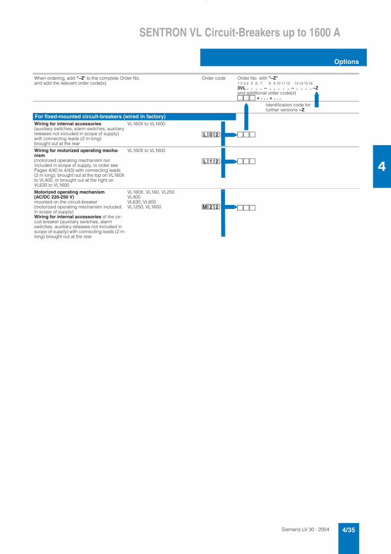
Siemens LV 30 · 2004 4/35
SENTRON VL Circuit-Breakers up to 1600 A
Options
4
▲
▲
When ordering, add "–Z" to the complete Order No. and add the relevant order code(s).
Order code Order No. with "–Z"1 2 3 4 5 6 7 8 9 10 11 12 13 14 15 163VL . . . . – . . . . . – . . . . –Zand additional order code(s)@@@ + . . . + . . .
Identification code for further versions –Z
For fixed-mounted circuit-breakers (wired in factory)Wiring for internal accessories(auxiliary switches, alarm switches, auxiliary releases not included in scope of supply) with connecting leads (2 m long) brought out at the rear
VL160X to VL1600
çÒÔ @@@
Wiring for motorized operating mecha-nism(motorized operating mechanism nor included in scope of supply, to order see Pages 4/40 to 4/43) with connecting leads (2 m long), brought out at the top on VL160X to VL400, or brought out at the right on VL630 to VL1600
VL160X to VL1600
çÓÔ @@@
Motorized operating mechanism (AC/DC 220-250 V)mounted on the circuit-breaker (motorized operating mechanism included in scope of supply) Wiring for internal accessories of the cir-cuit-breaker (auxiliary switches, alarm switches, auxiliary releases not included in scope of supply) with connecting leads (2 m long) brought out at the rear
VL160X, VL160, VL250 VL400VL630, VL800 VL1250, VL1600 èÔÔ @@@
▲▲
▲
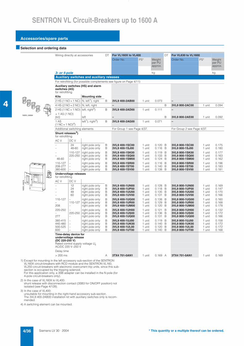
Siemens LV 30 · 20044/36
SENTRON VL Circuit-Breakers up to 1600 A
Accessories/spare parts
4
■ Selection and ordering data
1) Except for mounting in the left accessory sub-section of the SENTRON VL160X circuit-breakers with RCD module and the SENTRON VL160, VL250 circuit-breakers with electronic overcurrent trip units, since this sub-section is occupied by the tripping solenoid. For this application only, a 3SB adapter can be installed in the N pole (for 4-pole circuit-breakers only).
2) In the case of VL160X to VL400: shunt release with disconnection contact (3SB3 for ON/OFF position) not isolated (see Page 4/128).
3) In the case of VL400: unsuitable for mounting in the right-hand accessory sub-section. The 3VL9 400-2AB00 installation kit with auxiliary switches only is recom-mended.
4) A switching element can be mounted.
Wiring directly at accessories DT For VL160X to VL400 DT For VL630 to VL1600
Order No. PS* Weight per PU approx.
Order No. PS* Weight per PU approx.
3- or 4-pole kg kg
Auxiliary switches and auxiliary releasesFor retrofitting (for possible complements see figure on Page 4/11)
Auxiliary switches (HS) and alarm switches (AS)for retrofitting
Kits Mounting side
2 HS (1 NO + 1 NC) N, left1), right B 3VL9 400-2AB00 1 unit 0.073 –
4 HS (2 NO + 2 NC) N, left, right – B 3VL9 800-2AC00 1 unit 0.094
2 HS (1 NC + 1 NO) left, right3) B 3VL9 400-2AD00 1 unit 0.111 –
+ 1 AS (1 NO) (kit) left – B 3VL9 800-2AE00 1 unit 0.092
1 AS (1 NC + 1 NO)4)
left1), right3) B 3VL9 400-2AG00 1 unit 0.071 –
Additional switching elements For Group 1 see Page 4/37. For Group 2 see Page 4/37.
Shunt releases2)for retrofitting
AC V DC V
– 24 right pole only B 3VL9 400-1SC00 1 unit 0.120 B 3VL9 800-1SC00 1 unit 0.175– 48-60 right pole only B 3VL9 400-1SJ00 1 unit 0.116 B 3VL9 800-1SJ00 1 unit 0.180
– 110-127 right pole only B 3VL9 400-1SK00 1 unit 0.119 B 3VL9 800-1SK00 1 unit 0.177– 220-250 right pole only B 3VL9 400-1SQ00 1 unit 0.133 B 3VL9 800-1SQ00 1 unit 0.16348-60 – right pole only B 3VL9 400-1SM00 1 unit 0.124 B 3VL9 800-1SM00 1 unit 0.162
110-127 – right pole only B 3VL9 400-1SR00 1 unit 0.116 B 3VL9 800-1SR00 1 unit 0.196208-277 – right pole only B 3VL9 400-1ST00 1 unit 0.140 B 3VL9 800-1ST00 1 unit 0.183380-600 – right pole only B 3VL9 400-1SV00 1 unit 0.138 B 3VL9 800-1SV00 1 unit 0.181
Undervoltage releasesfor retrofitting
AC V DC V
– 12 right pole only B 3VL9 400-1UN00 1 unit 0.128 B 3VL9 800-1UN00 1 unit 0.169– 24 right pole only B 3VL9 400-1UP00 1 unit 0.118 B 3VL9 800-1UP00 1 unit 0.147– 48 right pole only B 3VL9 400-1UU00 1 unit 0.135 B 3VL9 800-1UU00 1 unit 0.170– 60 right pole only B 3VL9 400-1UV00 1 unit 0.131 B 3VL9 800-1UV00 1 unit 0.166
110-127 – right pole only B 3VL9 400-1UG00 1 unit 0.138 B 3VL9 800-1UG00 1 unit 0.160– 110-127 right pole only B 3VL9 400-1UR00 1 unit 0.129 B 3VL9 800-1UR00 1 unit 0.168208 – right pole only B 3VL9 400-1UM00 1 unit 0.120 B 3VL9 800-1UM00 1 unit 0.178
220-250 – right pole only B 3VL9 400-1UH00 1 unit 0.121 B 3VL9 800-1UH00 1 unit 0.132– 220-250 right pole only B 3VL9 400-1US00 1 unit 0.136 B 3VL9 800-1US00 1 unit 0.172277 – right pole only B 3VL9 400-1UQ00 1 unit 0.131 B 3VL9 800-1UQ00 1 unit 0.166
380-415 – right pole only B 3VL9 400-1UJ00 1 unit 0.119 B 3VL9 800-1UJ00 1 unit 0.158440-480 – right pole only B 3VL9 400-1UK00 1 unit 0.140 B 3VL9 800-1UK00 1 unit 0.172500-525 – right pole only B 3VL9 400-1UL00 1 unit 0.120 B 3VL9 800-1UL00 1 unit 0.172600 – right pole only B 3VL9 400-1UT00 1 unit 0.140 B 3VL9 800-1UT00 1 unit 0.168
Time-delay device for undervoltage release (DC 220-250 V)Rated control supply voltage UsAC/DC 220 V–250 V
Delay time
> 200 ms A 3TX4 701-0AN1 1 unit 0.169 A 3TX4 701-0AN1 1 unit 0.169
����������
�����
����
�
* This quantity or a multiple thereof can be ordered.
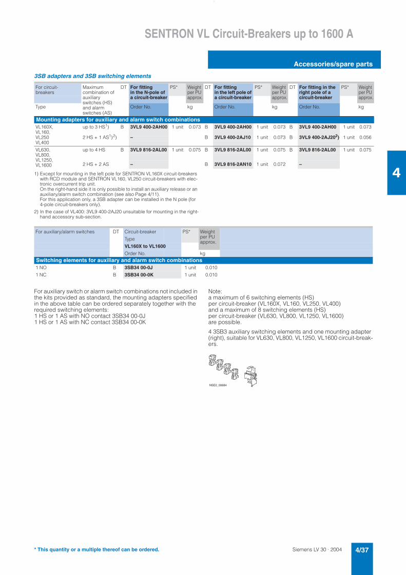
Siemens LV 30 · 2004 4/37
SENTRON VL Circuit-Breakers up to 1600 A
Accessories/spare parts
4
3SB adapters and 3SB switching elements
1) Except for mounting in the left pole for SENTRON VL160X circuit-breakers with RCD module and SENTRON VL160, VL250 circuit-breakers with elec-tronic overcurrent trip unit. On the right-hand side it is only possible to install an auxiliary release or an auxiliary/alarm switch combination (see also Page 4/11). For this application only, a 3SB adapter can be installed in the N pole (for 4-pole circuit-breakers only).
2) In the case of VL400: 3VL9 400-2AJ20 unsuitable for mounting in the right-hand accessory sub-section.
For auxiliary switch or alarm switch combinations not included in the kits provided as standard, the mounting adapters specified in the above table can be ordered separately together with the required switching elements: 1 HS or 1 AS with NO contact 3SB34 00-0J 1 HS or 1 AS with NC contact 3SB34 00-0K
Note:a maximum of 6 switching elements (HS) per circuit-breaker (VL160X, VL160, VL250, VL400) and a maximum of 8 switching elements (HS) per circuit-breaker (VL630, VL800, VL1250, VL1600) are possible.
4 3SB3 auxiliary switching elements and one mounting adapter (right), suitable for VL630, VL800, VL1250, VL1600 circuit-break-ers.
For circuit-breakers
Maximumcombination of auxiliary switches (HS) and alarm switches (AS)
DT For fitting in the N-pole of a circuit-breaker
PS* Weight per PU approx.
DT For fitting in the left pole of a circuit-breaker
PS* Weight per PU approx.
DT For fitting in the right pole of a circuit-breaker
PS* Weight per PU approx.
Type Order No. kg Order No. kg Order No. kg
Mounting adapters for auxiliary and alarm switch combinationsVL160X, up to 3 HS1) B 3VL9 400-2AH00 1 unit 0.073 B 3VL9 400-2AH00 1 unit 0.073 B 3VL9 400-2AH00 1 unit 0.073VL160,VL250 2 HS + 1 AS1)2) – B 3VL9 400-2AJ10 1 unit 0.073 B 3VL9 400-2AJ202) 1 unit 0.056VL400
VL630,VL800,VL1250,VL1600
up to 4 HS B 3VL9 816-2AL00 1 unit 0.075 B 3VL9 816-2AL00 1 unit 0.075 B 3VL9 816-2AL00 1 unit 0.075
2 HS + 2 AS – B 3VL9 816-2AN10 1 unit 0.072 –
For auxiliary/alarm switches DT Circuit-breaker PS* Weight per PU approx.
Type
VL160X to VL1600
Order No. kgSwitching elements for auxiliary and alarm switch combinations1 NO B 3SB34 00-0J 1 unit 0.010
1 NC B 3SB34 00-0K 1 unit 0.010
����������
* This quantity or a multiple thereof can be ordered.
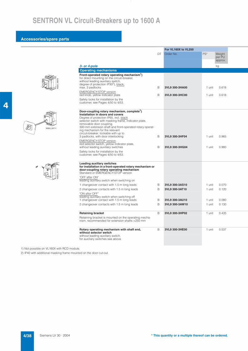
Siemens LV 30 · 20044/38
SENTRON VL Circuit-Breakers up to 1600 A
Accessories/spare parts
4
1) Not possible on VL160X with RCD module.
2) IP40 with additional masking frame mounted on the door cut-out.
For VL160X to VL250
DT Order No. PS* Weight per PU approx.
3- or 4-pole kg
Operating mechanismsFront-operated rotary operating mechanism1)for direct mounting on the circuit-breaker, without leading auxiliary switch, degree of protection IP302), black,max. 3 padlocks B 3VL9 300-3HA00 1 unit 0.618
EMERGENCY-STOP versionred knob, yellow indicator plate B 3VL9 300-3HC00 1 unit 0.618
Safety locks for installation by the customer, see Pages 4/50 to 4/53.
Door-coupling rotary mechanism, complete1)Installation in doors and coversDegree of protection IP65, incl. blackselector switch with masking frame, indicator plate, removable door coupling, 300 mm extension shaft and front-operated rotary operat-ing mechanism for the relevant circuit-breaker, lockable with up to 3 padlocks, with door interlocking B 3VL9 300-3HF04 1 unit 0.965
EMERGENCY-STOP versionred selector switch, yellow indicator plate, without leading auxiliary switches B 3VL9 300-3HG04 1 unit 0.980
Safety locks for installation by the customer, see Pages 4/50 to 4/53.
Leading auxiliary switches for installation in a front-operated rotary mechanism or door-coupling rotary operating mechanismStandard or EMERGENCY-STOP version
"OFF after ON"leading auxiliary switch when switching on
1 changeover contact with 1.5 m long leads B 3VL9 300-3AS10 1 unit 0.070
2 changeover contacts with 1.5 m long leads B 3VL9 300-3AT10 1 unit 0.120
"ON after OFF"leading auxiliary switch when switching off1 changeover contact with 1.5 m long leads B 3VL9 300-3AU10 1 unit 0.080
2 changeover contacts with 1.5 m long leads B 3VL9 300-3AW10 1 unit 0.130
Retaining bracket B 3VL9 300-3HP02 1 unit 0.435
Retaining bracket is mounted on the operating mecha-nism, recommended for extension shafts >250 mm
Rotary operating mechanism with shaft end, without selector switch
B 3VL9 300-3HE00 1 unit 0.537
without leading auxiliary switch, for auxiliary switches see above
�����
����
�
����������
�����
����
�
* This quantity or a multiple thereof can be ordered.
Siemens LV 30 · 2004 4/39
SENTRON VL Circuit-Breakers up to 1600 A
Accessories/spare parts
4
For VL400 For VL630 to VL800 For VL1250 to VL1600
DT Order No. PS* Weight per PU approx.
DT Order No. PS* Weight per PU approx.
DT Order No. PS* Weight per PU approx.
kg kg kg
B 3VL9 400-3HA00 1 unit 0.618 B 3VL9 600-3HA00 1 unit 1.370 B 3VL9 800-3HA00 1 unit 1.370
B 3VL9 400-3HC00 1 unit 0.618 B 3VL9 600-3HC00 1 unit 1.360 B 3VL9 800-3HC00 1 unit 1.370
B 3VL9 400-3HF04 1 unit 0.965 B 3VL9 600-3HF04 1 unit 2.460 B 3VL9 800-3HF04 1 unit 4.100
B 3VL9 400-3HG04 1 unit 1.100 B 3VL9 600-3HG04 1 unit 2.460 B 3VL9 800-3HG04 1 unit 4.100
B 3VL9 400-3AS10 1 unit 0.070 B 3VL9 600-3AS10 1 unit 0.097 B 3VL9 800-3AS10 1 unit 0.090
B 3VL9 400-3AT10 1 unit 0.120 B 3VL9 600-3AT10 1 unit 0.146 B 3VL9 800-3AT10 1 unit 0.145
B 3VL9 400-3AU10 1 unit 0.070 B 3VL9 600-3AU10 1 unit 0.082 B 3VL9 800-3AU10 1 unit 0.098
B 3VL9 400-3AW10 1 unit 0.120 B 3VL9 600-3AW10 1 unit 0.143 B 3VL9 800-3AW10 1 unit 0.143
B 3VL9 400-3HP02 1 unit 0.435 B 3VL9 600-3HP02 1 unit 0.570 B 3VL9 800-3HP02 1 unit 0.723
B 3VL9 400-3HE00 1 unit 0.618 B 3VL9 600-3HE00 1 unit 1.250 B 3VL9 800-3HE00 1 unit 2.760
* This quantity or a multiple thereof can be ordered.
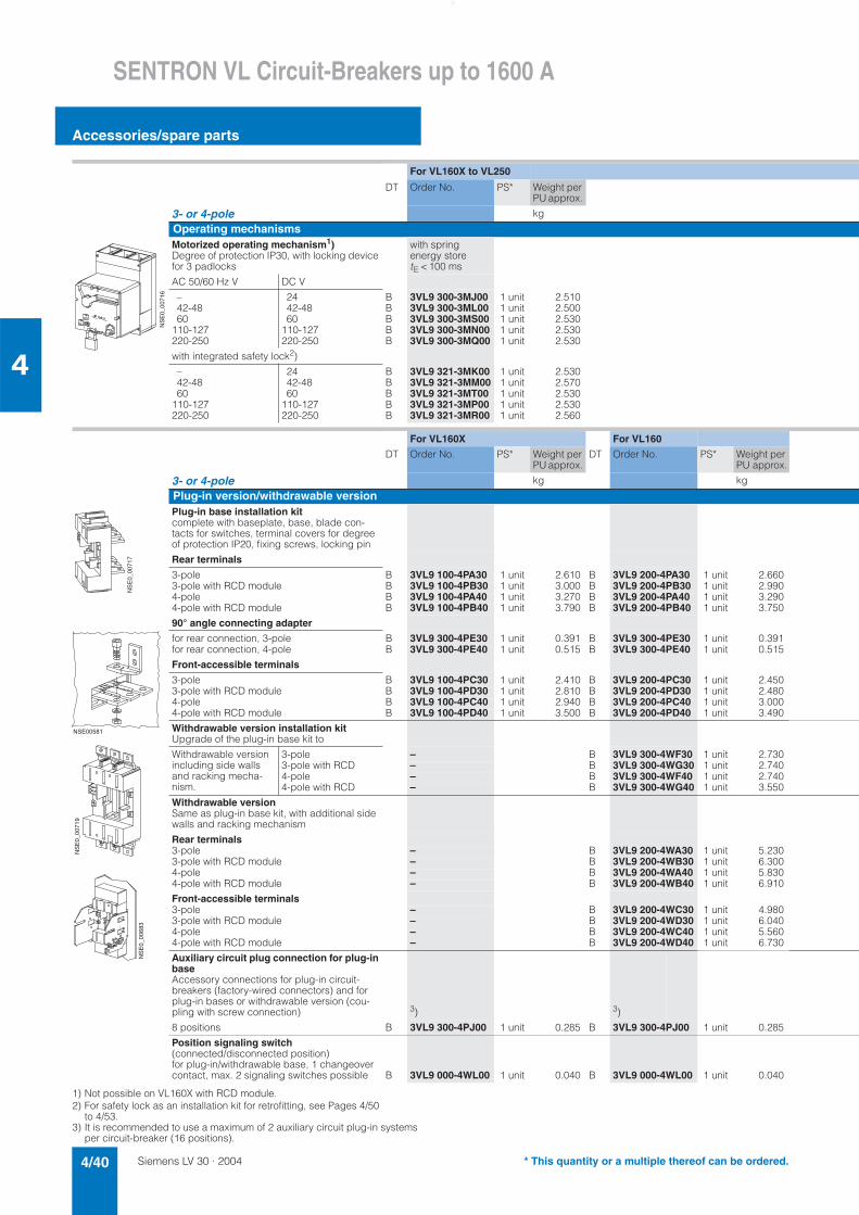
Siemens LV 30 · 20044/40
SENTRON VL Circuit-Breakers up to 1600 A
Accessories/spare parts
4
1) Not possible on VL160X with RCD module.2) For safety lock as an installation kit for retrofitting, see Pages 4/50
to 4/53.3) It is recommended to use a maximum of 2 auxiliary circuit plug-in systems
per circuit-breaker (16 positions).
For VL160X to VL250
DT Order No. PS* Weight per PU approx.
3- or 4-pole kg
Operating mechanismsMotorized operating mechanism1)Degree of protection IP30, with locking device for 3 padlocks
with spring energy storetE < 100 ms
AC 50/60 Hz V DC V
– 24 B 3VL9 300-3MJ00 1 unit 2.51042-48 42-48 B 3VL9 300-3ML00 1 unit 2.50060 60 B 3VL9 300-3MS00 1 unit 2.530
110-127 110-127 B 3VL9 300-3MN00 1 unit 2.530220-250 220-250 B 3VL9 300-3MQ00 1 unit 2.530
with integrated safety lock2)
– 24 B 3VL9 321-3MK00 1 unit 2.53042-48 42-48 B 3VL9 321-3MM00 1 unit 2.57060 60 B 3VL9 321-3MT00 1 unit 2.530
110-127 110-127 B 3VL9 321-3MP00 1 unit 2.530220-250 220-250 B 3VL9 321-3MR00 1 unit 2.560
For VL160X For VL160
DT Order No. PS* Weight per PU approx.
DT Order No. PS* Weight per PU approx.
3- or 4-pole kg kg
Plug-in version/withdrawable versionPlug-in base installation kitcomplete with baseplate, base, blade con-tacts for switches, terminal covers for degree of protection IP20, fixing screws, locking pin
Rear terminals
3-pole B 3VL9 100-4PA30 1 unit 2.610 B 3VL9 200-4PA30 1 unit 2.6603-pole with RCD module B 3VL9 100-4PB30 1 unit 3.000 B 3VL9 200-4PB30 1 unit 2.9904-pole B 3VL9 100-4PA40 1 unit 3.270 B 3VL9 200-4PA40 1 unit 3.2904-pole with RCD module B 3VL9 100-4PB40 1 unit 3.790 B 3VL9 200-4PB40 1 unit 3.750
90° angle connecting adapter
for rear connection, 3-pole B 3VL9 300-4PE30 1 unit 0.391 B 3VL9 300-4PE30 1 unit 0.391for rear connection, 4-pole B 3VL9 300-4PE40 1 unit 0.515 B 3VL9 300-4PE40 1 unit 0.515
Front-accessible terminals
3-pole B 3VL9 100-4PC30 1 unit 2.410 B 3VL9 200-4PC30 1 unit 2.4503-pole with RCD module B 3VL9 100-4PD30 1 unit 2.810 B 3VL9 200-4PD30 1 unit 2.4804-pole B 3VL9 100-4PC40 1 unit 2.940 B 3VL9 200-4PC40 1 unit 3.0004-pole with RCD module B 3VL9 100-4PD40 1 unit 3.500 B 3VL9 200-4PD40 1 unit 3.490
Withdrawable version installation kitUpgrade of the plug-in base kit to
Withdrawable version including side walls and racking mecha-nism.
3-pole – B 3VL9 300-4WF30 1 unit 2.7303-pole with RCD – B 3VL9 300-4WG30 1 unit 2.7404-pole – B 3VL9 300-4WF40 1 unit 2.7404-pole with RCD – B 3VL9 300-4WG40 1 unit 3.550
Withdrawable versionSame as plug-in base kit, with additional side walls and racking mechanism
Rear terminals3-pole – B 3VL9 200-4WA30 1 unit 5.2303-pole with RCD module – B 3VL9 200-4WB30 1 unit 6.3004-pole – B 3VL9 200-4WA40 1 unit 5.8304-pole with RCD module – B 3VL9 200-4WB40 1 unit 6.910
Front-accessible terminals3-pole – B 3VL9 200-4WC30 1 unit 4.9803-pole with RCD module – B 3VL9 200-4WD30 1 unit 6.0404-pole – B 3VL9 200-4WC40 1 unit 5.5604-pole with RCD module – B 3VL9 200-4WD40 1 unit 6.730
Auxiliary circuit plug connection for plug-in baseAccessory connections for plug-in circuit-breakers (factory-wired connectors) and for plug-in bases or withdrawable version (cou-pling with screw connection) 3) 3)
8 positions B 3VL9 300-4PJ00 1 unit 0.285 B 3VL9 300-4PJ00 1 unit 0.285
Position signaling switch (connected/disconnected position)for plug-in/withdrawable base, 1 changeover contact, max. 2 signaling switches possible B 3VL9 000-4WL00 1 unit 0.040 B 3VL9 000-4WL00 1 unit 0.040
�����
����
�
�����
����
�
��������
�����
����
�
�����
����
�
* This quantity or a multiple thereof can be ordered.
Siemens LV 30 · 2004 4/41
SENTRON VL Circuit-Breakers up to 1600 A
Accessories/spare parts
4
For VL400
DT Order No. PS* Weight per PU approx.
kg
with spring energy storetE < 100 ms
B 3VL9 400-3MJ00 1 unit 2.510B 3VL9 400-3ML00 1 unit 2.510B 3VL9 400-3MS00 1 unit 2.510B 3VL9 400-3MN00 1 unit 2.510B 3VL9 400-3MQ00 1 unit 2.510
B 3VL9 415-3MK00 1 unit 2.530B 3VL9 415-3MM00 1 unit 2.530B 3VL9 415-3MT00 1 unit 2.530B 3VL9 415-3MP00 1 unit 2.530B 3VL9 415-3MR00 1 unit 2.530
For VL250 For VL400
DT Order No. PS* Weight per PU approx.
DT Order No. PS* Weight per PU approx.
kg kg
B 3VL9 300-4PA30 1 unit 3.400 B 3VL9 400-4PA30 1 unit 3.400B 3VL9 300-4PB30 1 unit 3.120 B –4)B 3VL9 300-4PA40 1 unit 3.400 B 3VL9 400-4PA40 1 unit 3.400B 3VL9 300-4PB40 1 unit 3.890 B 3VL9 400-4PB40 1 unit 3.890
B 3VL9 300-4PE30 1 unit 0.391 B –B 3VL9 300-4PE40 1 unit 0.515 B –
B 3VL9 300-4PC30 1 unit 2.550 B 3VL9 400-4PC30 1 unit 2.450B 3VL9 300-4PD30 1 unit 2.970 B –4)B 3VL9 300-4PC40 1 unit 2.660 B 3VL9 400-4PC40 1 unit 3.000B 3VL9 300-4PD40 1 unit 3.650 B 3VL9 400-4PD40 1 unit 3.490
B 3VL9 300-4WF30 1 unit 2.730 B 3VL9 400-4WF30 1 unit 2.730B 3VL9 300-4WG30 1 unit 2.740 B –4)B 3VL9 300-4WF40 1 unit 2.740 B 3VL9 400-4WF40 1 unit 2.740B 3VL9 300-4WG40 1 unit 3.550 B 3VL9 400-4WG40 1 unit 3.550
B 3VL9 300-4WA30 1 unit 5.190 B 3VL9 400-4WA30 1 unit 5.230B 3VL9 300-4WB30 1 unit 9.800 B –4)B 3VL9 300-4WA40 1 unit 6.040 B 3VL9 400-4WA40 1 unit 5.830B 3VL9 300-4WB40 1 unit 7.490 B 3VL9 400-4WB40 1 unit 6.910
B 3VL9 300-4WC30 1 unit 5.100 B 3VL9 400-4WC30 1 unit 4.980B 3VL9 300-4WD30 1 unit 6.240 B –4)B 3VL9 300-4WC40 1 unit 5.710 B 3VL9 400-4WC40 1 unit 5.560B 3VL9 300-4WD40 1 unit 6.890 B 3VL9 400-4WD40 1 unit 6.730
3) 5)
B 3VL9 300-4PJ00 1 unit 0.285 B 3VL9 400-4PJ00 1 unit on req.
B 3VL9 000-4WL00 1 unit 0.040 B 3VL9 000-4WL00 1 unit 0.040
4) For 3-pole applications please use 4-pole withdrawable version with 4-pole RCD module.
5) It is recommended to use a maximum of 3 auxiliary circuit plug-in systems per circuit-breaker (24 positions).
* This quantity or a multiple thereof can be ordered.
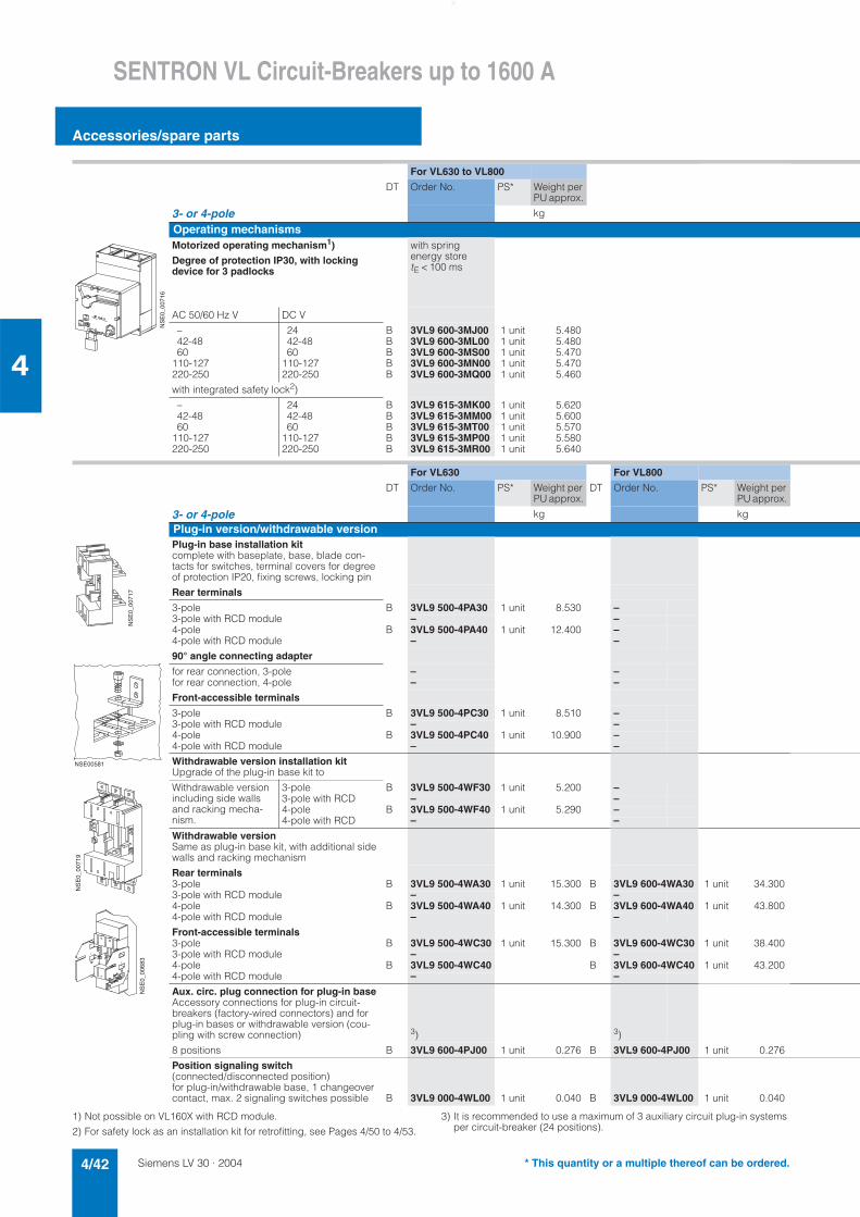
Siemens LV 30 · 20044/42
SENTRON VL Circuit-Breakers up to 1600 A
Accessories/spare parts
4
1) Not possible on VL160X with RCD module.
2) For safety lock as an installation kit for retrofitting, see Pages 4/50 to 4/53.
3) It is recommended to use a maximum of 3 auxiliary circuit plug-in systems per circuit-breaker (24 positions).
For VL630 to VL800
DT Order No. PS* Weight per PU approx.
3- or 4-pole kg
Operating mechanismsMotorized operating mechanism1)
Degree of protection IP30, with locking device for 3 padlocks
with spring energy storetE < 100 ms
AC 50/60 Hz V DC V
– 24 B 3VL9 600-3MJ00 1 unit 5.48042-48 42-48 B 3VL9 600-3ML00 1 unit 5.48060 60 B 3VL9 600-3MS00 1 unit 5.470
110-127 110-127 B 3VL9 600-3MN00 1 unit 5.470220-250 220-250 B 3VL9 600-3MQ00 1 unit 5.460
with integrated safety lock2)
– 24 B 3VL9 615-3MK00 1 unit 5.62042-48 42-48 B 3VL9 615-3MM00 1 unit 5.60060 60 B 3VL9 615-3MT00 1 unit 5.570
110-127 110-127 B 3VL9 615-3MP00 1 unit 5.580220-250 220-250 B 3VL9 615-3MR00 1 unit 5.640
For VL630 For VL800
DT Order No. PS* Weight per PU approx.
DT Order No. PS* Weight per PU approx.
3- or 4-pole kg kg
Plug-in version/withdrawable versionPlug-in base installation kitcomplete with baseplate, base, blade con-tacts for switches, terminal covers for degree of protection IP20, fixing screws, locking pin
Rear terminals
3-pole B 3VL9 500-4PA30 1 unit 8.530 –3-pole with RCD module – –4-pole B 3VL9 500-4PA40 1 unit 12.400 –4-pole with RCD module – –
90° angle connecting adapter
for rear connection, 3-pole – –for rear connection, 4-pole – –
Front-accessible terminals
3-pole B 3VL9 500-4PC30 1 unit 8.510 –3-pole with RCD module – –4-pole B 3VL9 500-4PC40 1 unit 10.900 –4-pole with RCD module – –
Withdrawable version installation kitUpgrade of the plug-in base kit to
Withdrawable version including side walls and racking mecha-nism.
3-pole B 3VL9 500-4WF30 1 unit 5.200 –3-pole with RCD – –4-pole B 3VL9 500-4WF40 1 unit 5.290 –4-pole with RCD – –
Withdrawable versionSame as plug-in base kit, with additional side walls and racking mechanism
Rear terminals3-pole B 3VL9 500-4WA30 1 unit 15.300 B 3VL9 600-4WA30 1 unit 34.3003-pole with RCD module – –4-pole B 3VL9 500-4WA40 1 unit 14.300 B 3VL9 600-4WA40 1 unit 43.8004-pole with RCD module – –
Front-accessible terminals3-pole B 3VL9 500-4WC30 1 unit 15.300 B 3VL9 600-4WC30 1 unit 38.4003-pole with RCD module – –4-pole B 3VL9 500-4WC40 B 3VL9 600-4WC40 1 unit 43.2004-pole with RCD module – –
Aux. circ. plug connection for plug-in baseAccessory connections for plug-in circuit-breakers (factory-wired connectors) and for plug-in bases or withdrawable version (cou-pling with screw connection) 3) 3)
8 positions B 3VL9 600-4PJ00 1 unit 0.276 B 3VL9 600-4PJ00 1 unit 0.276
Position signaling switch(connected/disconnected position)for plug-in/withdrawable base, 1 changeover contact, max. 2 signaling switches possible B 3VL9 000-4WL00 1 unit 0.040 B 3VL9 000-4WL00 1 unit 0.040
�����
����
�
�����
����
�
��������
�����
����
�
�����
����
�
* This quantity or a multiple thereof can be ordered.
Siemens LV 30 · 2004 4/43
SENTRON VL Circuit-Breakers up to 1600 A
Accessories/spare parts
4
For VL1250 to VL1600
DT Order No. PS* Weight per PU approx.
kg
Motorized oper. mech. without spring energy store (not for syn-chronization)tE < 5 s
B 3VL9 800-3MJ00 1 unit 7.540B 3VL9 800-3ML00 1 unit 7.540B 3VL9 800-3MS00 1 unit 7.540B 3VL9 800-3MN00 1 unit 0.750B 3VL9 800-3MQ00 1 unit 7.580
B 3VL9 815-3MK00 1 unit 7.540B 3VL9 815-3MM00 1 unit 7.540B 3VL9 815-3MT00 1 unit 7.540B 3VL9 815-3MP00 1 unit 7.540B 3VL9 815-3MR00 1 unit 7.730
For VL1250 For VL1600
DT Order No. PS* Weight per PU approx.
DT Order No. PS* Weight per PU approx.
kg kg
– –– –– –– –
– –– –
– –– –– –– –
– –– –– –– –
B 3VL9 800-4WA30 1 unit 30.300 B 3VL9 800-4WA30 1 unit 30.300– –
B 3VL9 800-4WA40 1 unit 28.400 B 3VL9 800-4WA40 1 unit 28.400– –
B 3VL9 800-4WC30 1 unit 41.800 B 3VL9 800-4WC30 1 unit 41.800– –
B 3VL9 800-4WC40 1 unit 41.100 B 3VL9 800-4WC40 1 unit 41.100– –
3)3)
B 3VL9 800-4PJ00 1 unit 0.289 B 3VL9 800-4PJ00 1 unit 0.289
B 3VL9 000-4WL00 1 unit 0.040 B 3VL9 000-4WL00 1 unit 0.040
* This quantity or a multiple thereof can be ordered.
Siemens LV 30 · 20044/44
SENTRON VL Circuit-Breakers up to 1600 A
Accessories/spare parts
4
RCD module
1) Only the right-hand accessory compartment and the neutral conductor (4-pole) accessory compartment can be used for the installation of acces-sories, see Page 4/11.
2) The installation kit consists of the mounting plate, wiring and covers for switches and RCD module (for 75 mm standard mounting rail). The RCD module (3VL9 112-5GA30/-5GA40) must be ordered separately.
Circuit-breakers for system protection, only for TM, starters, disconnectors
Ratedcurrent In
Residual currents Iadjustable
Delay tdadjustable
Rated operat-ing voltage Ue
DT Circuit-breaker 3-pole
PS* Weight per PU approx.
DT Circuit-breaker 4-pole
PS* Weight per PU approx.
3- and 4-pole A A S AC V Order No. kg Order No. kg
VL160X 0.03 instanta-neous
(Bottom mounting1) 160 0.10 0.06 127-480 B 3VL9 112-5GA30 1 unit 1.510 B 3VL9 112-5GA40 1 unit 1.840
(Mounting kit for left side, without RCD)1)2)
0.30
0.50
1.00
3.00
0.10
0.25
0.50
1.00
B 3VL9 112-5GB30 1 unit 1.960 B 3VL9 112-5GB40 1 unit 2.340
VL160 160 127-480 B 3VL9 216-5GC30 1 unit 1.430 B 3VL9 216-5GC40 1 unit 1.740
230-690 B 3VL9 216-5GD30 1 unit 1.440 B 3VL9 216-5GD40 1 unit 1.750
VL250 250 127-480 B 3VL9 325-5GE30 1 unit 1.500 B 3VL9 325-5GE40 1 unit 1.800
230-690 B 3VL9 325-5GF30 1 unit 1.490 B 3VL9 325-5GF40 1 unit 1.820
VL400 400 127-480 – B 3VL9 440-5GG40 1 unit 3.320
230-690 – B 3VL9 440-5GH40 1 unit 3.320
* This quantity or a multiple thereof can be ordered.
Siemens LV 30 · 2004 4/45
SENTRON VL Circuit-Breakers up to 1600 A
Accessories/spare parts
4
Circuit-breakers with RCD module
1) Only the right-hand accessory compartment and the neutral conductor (4-pole) accessory compartment can be used for the installation of acces-sories, see Page 4/11.
Circuit-breakers for system pro-tection, only for TM, starters, disconnectors
Ratedcurrent In
Residualcurrents Iadjustable
Delay tdadjustable
Rated operat-ing voltage Ue
Circuit-breaker 3-pole
Circuit-breaker 4-pole
3- and 4-pole A A S AC V
Order No. with "–Z"
3VL. . . . - . D . . . - . . . .-Z
and additional order code
@@@
Order No. with "–Z"
3VL. . . . - . E . . . - . . . .-Z
and additional order code
@@@
VL160X 0.03 instantaneous
(bottom mounting) 160 0.10 0.06 127-480 A 0 11) A 0 11)
0.30 0.10
0.50 0.25
VL160 160 1.00 0.50 127-480 A 0 1 A 0 1
3.00 1.00 230-690 A 0 2 A 0 2
VL250 250 127-480 A 0 1 A 0 1
230-690 A 0 2 A 0 2
VL400 400 127-480 – A 0 1
230-690 – A 0 2
▲▲▲▲▲▲
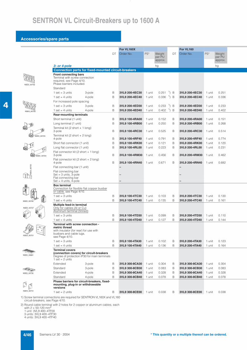
Siemens LV 30 · 20044/46
SENTRON VL Circuit-Breakers up to 1600 A
Accessories/spare parts
4
1) Screw terminal connections are required for SENTRON VL160X and VL160 circuit-breakers, see Page 4/10.
2) Round cable terminal with 2 holes for 2 copper or aluminum cables, each with 2 × 50-120 mm2
1 unit: 3VL9 400–4TF003 units: 3VL9 400–4TF30 4 units: 3VL9 400–4TF40
For VL160X For VL160
DT Order No. PS* Weight per PU approx.
DT Order No. PS* Weight per PU approx.
3- or 4-pole kg kg
Connection parts for fixed-mounted circuit-breakersFront connecting barsTerminal with screw connection required, see Page 4/10. Phase barriers included.
Standard
1 set = 3 units 3-pole B 3VL9 200-4EC30 1 unit 0.251 1) B 3VL9 200-4EC30 1 unit 0.251
1 set = 4 units 4-pole B 3VL9 200-4EC40 1 unit 0.336 1) B 3VL9 200-4EC40 1 unit 0.336
For increased pole spacing
1 set = 3 units 3-pole B 3VL9 200-4ED30 1 unit 0.233 1) B 3VL9 200-4ED30 1 unit 0.233
1 set = 4 units 4-pole B 3VL9 200-4ED40 1 unit 0.402 1) B 3VL9 200-4ED40 1 unit 0.402
Rear-mounting terminals
Short terminal (1 unit) B 3VL9 100-4RA00 1 unit 0.152 B 3VL9 200-4RA00 1 unit 0.151
Long terminal (1 unit) B 3VL9 100-4RB00 1 unit 0.250 B 3VL9 200-4RB00 1 unit 0.268
Terminal kit (2 short + 1 long)3-pole B 3VL9 100-4RC30 1 unit 0.525 B 3VL9 200-4RC30 1 unit 0.514
Terminal kit (2 short + 2 long)4-pole B 3VL9 100-4RF40 1 unit 0.791 B 3VL9 200-4RF40 1 unit 0.774
Short flat connector (1 unit) B 3VL9 100-4RK00 1 unit 0.121 B 3VL9 200-4RK00 1 unit 0.120
Long flat connector (1 unit) B 3VL9 100-4RL00 1 unit 0.223 B 3VL9 200-4RL00 1 unit 0.231
Flat connector kit (2 short + 1 long)3-pole B 3VL9 100-4RM30 1 unit 0.456 B 3VL9 200-4RM30 1 unit 0.462
Flat connector kit (2 short + 2 long)4-pole B 3VL9 100-4RN40 1 unit 0.671 B 3VL9 200-4RN40 1 unit 0.682
Flat connecting bar (1 unit) – –
Flat connecting barSet = 3 units, 3-pole – –Flat connecting barSet = 4 units, 4-pole – –
Box terminalConnection for flexible flat copper busbaror cable, see Page 4/10.
1 set = 3 units B 3VL9 100-4TC30 1 unit 0.103 B 3VL9 200-4TC30 1 unit 0.130
1 set = 4 units B 3VL9 100-4TC40 1 unit 0.135 B 3VL9 200-4TC40 1 unit 0.161
Multiple feed-in terminalOnly for cables (Al or Cu)Aluminum terminal (tinned)
1 set = 3 units B 3VL9 100-4TD30 1 unit 0.099 B 3VL9 200-4TD30 1 unit 0.110
1 set = 4 units B 3VL9 100-4TD40 1 unit 0.127 B 3VL9 200-4TD40 1 unit 0.144
Terminal with screw connection - metric threadwith insulator (for rear) for use withbusbars and cable lugs, see Page 4/10.
1 set = 3 units B 3VL9 100-4TA30 1 unit 0.102 B 3VL9 200-4TA30 1 unit 0.123
1 set = 4 units B 3VL9 100-4TA40 1 unit 0.136 B 3VL9 200-4TA40 1 unit 0.164
Terminal covers (connection covers) for circuit-breakersDegree of protection IP30 for main terminals 1 set = 2 units
Extended 3-pole B 3VL9 300-8CA30 1 unit 0.304 B 3VL9 300-8CA30 1 unit 0.304
Standard 3-pole B 3VL9 300-8CB30 1 unit 0.083 B 3VL9 300-8CB30 1 unit 0.083
Extended 4-pole B 3VL9 300-8CA40 1 unit 0.328 B 3VL9 300-8CA40 1 unit 0.328
Standard 4-pole B 3VL9 300-8CB40 1 unit 0.078 B 3VL9 300-8CB40 1 unit 0.078
Phase barriers for circuit-breakers, fixed-mounting, plug-in or withdrawable versions
1 set = 2 units B 3VL9 300-8CE00 1 unit 0.038 B 3VL9 300-8CE00 1 unit 0.038
����������
����������
����������
����������
�����
����
�
����������
NSE0_00727
����������
����������
����������
����������
* This quantity or a multiple thereof can be ordered.
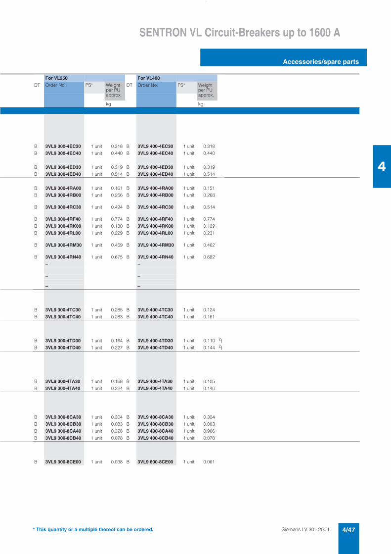
Siemens LV 30 · 2004 4/47
SENTRON VL Circuit-Breakers up to 1600 A
Accessories/spare parts
4
For VL250 For VL400
DT Order No. PS* Weight per PU approx.
DT Order No. PS* Weight per PU approx.
kg kg
B 3VL9 300-4EC30 1 unit 0.318 B 3VL9 400-4EC30 1 unit 0.318
B 3VL9 300-4EC40 1 unit 0.440 B 3VL9 400-4EC40 1 unit 0.440
B 3VL9 300-4ED30 1 unit 0.319 B 3VL9 400-4ED30 1 unit 0.319
B 3VL9 300-4ED40 1 unit 0.514 B 3VL9 400-4ED40 1 unit 0.514
B 3VL9 300-4RA00 1 unit 0.161 B 3VL9 400-4RA00 1 unit 0.151
B 3VL9 300-4RB00 1 unit 0.256 B 3VL9 400-4RB00 1 unit 0.268
B 3VL9 300-4RC30 1 unit 0.494 B 3VL9 400-4RC30 1 unit 0.514
B 3VL9 300-4RF40 1 unit 0.774 B 3VL9 400-4RF40 1 unit 0.774
B 3VL9 300-4RK00 1 unit 0.130 B 3VL9 400-4RK00 1 unit 0.129
B 3VL9 300-4RL00 1 unit 0.229 B 3VL9 400-4RL00 1 unit 0.231
B 3VL9 300-4RM30 1 unit 0.459 B 3VL9 400-4RM30 1 unit 0.462
B 3VL9 300-4RN40 1 unit 0.675 B 3VL9 400-4RN40 1 unit 0.682
– –
– –
– –
B 3VL9 300-4TC30 1 unit 0.285 B 3VL9 400-4TC30 1 unit 0.124
B 3VL9 300-4TC40 1 unit 0.283 B 3VL9 400-4TC40 1 unit 0.161
B 3VL9 300-4TD30 1 unit 0.164 B 3VL9 400-4TD30 1 unit 0.110 2)
B 3VL9 300-4TD40 1 unit 0.227 B 3VL9 400-4TD40 1 unit 0.144 2)
B 3VL9 300-4TA30 1 unit 0.168 B 3VL9 400-4TA30 1 unit 0.105
B 3VL9 300-4TA40 1 unit 0.224 B 3VL9 400-4TA40 1 unit 0.140
B 3VL9 300-8CA30 1 unit 0.304 B 3VL9 400-8CA30 1 unit 0.304
B 3VL9 300-8CB30 1 unit 0.083 B 3VL9 400-8CB30 1 unit 0.083
B 3VL9 300-8CA40 1 unit 0.328 B 3VL9 400-8CA40 1 unit 0.966
B 3VL9 300-8CB40 1 unit 0.078 B 3VL9 400-8CB40 1 unit 0.078
B 3VL9 300-8CE00 1 unit 0.038 B 3VL9 600-8CE00 1 unit 0.061
* This quantity or a multiple thereof can be ordered.
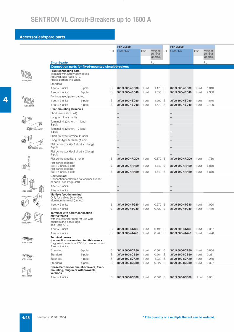
Siemens LV 30 · 20044/48
SENTRON VL Circuit-Breakers up to 1600 A
Accessories/spare parts
4
For VL630 For VL800
DT Order No. PS* Weight per PU approx.
DT Order No. PS* Weight per PU approx.
3- or 4-pole kg kg
Connection parts for fixed-mounted circuit-breakersFront connecting barsTerminal with screw connection required, see Page 4/10. Phase barriers included.
Standard
1 set = 3 units 3-pole B 3VL9 500-4EC30 1 unit 1.170 B 3VL9 600-4EC30 1 unit 1.810
1 set = 4 units 4-pole B 3VL9 500-4EC40 1 unit 1.550 B 3VL9 600-4EC40 1 unit 2.380
For increased pole spacing
1 set = 3 units 3-pole B 3VL9 500-4ED30 1 unit 1.200 B 3VL9 600-4ED30 1 unit 1.840
1 set = 4 units 4-pole B 3VL9 500-4ED40 1 unit 1.570 B 3VL9 600-4ED40 1 unit 2.400
Rear-mounting terminals
Short terminal (1 unit) – –
Long terminal (1 unit) – –
Terminal kit (2 short + 1 long)3-pole – –
Terminal kit (2 short + 2 long)4-pole – –
Short flat-type terminal (1 unit) – –
Long flat-type terminal (1 unit) – –
Flat connector kit (2 short + 1 long)3-pole – –
Flat connector kit (2 short + 2 long)4-pole – –
Flat connecting bar (1 unit) B 3VL9 500-4RG00 1 unit 0.372 B 3VL9 600-4RG00 1 unit 1.730
Flat connecting barSet = 3 units, 3-pole B 3VL9 500-4RH30 1 unit 1.540 B 3VL9 600-4RH30 1 unit 6.870Flat connecting barSet = 4 units, 4-pole B 3VL9 500-4RH40 1 unit 1.540 B 3VL9 600-4RH40 1 unit 6.870
Box terminalConnection for flexible flat copper busbaror cable, see Page 4/10.
1 set = 3 units – –
1 set = 4 units – –
Multiple feed-in terminalOnly for cables (Al or Cu)aluminum terminal (tinned)
1 set = 3 units B 3VL9 500-4TG30 1 unit 0.570 B 3VL9 600-4TG30 1 unit 1.090
1 set = 4 units B 3VL9 500-4TG40 1 unit 0.720 B 3VL9 600-4TG40 1 unit 1.410
Terminal with screw connection – metric threadwith insulator (for rear) for use withbusbars and cable lugs, see Page 4/10.
1 set = 3 units B 3VL9 500-4TA30 1 unit 0.195 B 3VL9 600-4TA30 1 unit 0.357
1 set = 4 units B 3VL9 500-4TA40 1 unit 0.260 B 3VL9 600-4TA40 1 unit 0.476
Terminal covers (connection covers) for circuit-breakersDegree of protection IP30 for main terminals 1 set = 2 units
Extended 3-pole B 3VL9 600-8CA30 1 unit 0.864 B 3VL9 600-8CA30 1 unit 0.864
Standard 3-pole B 3VL9 600-8CB30 1 unit 0.261 B 3VL9 600-8CB30 1 unit 0.261
Extended 4-pole B 3VL9 600-8CA40 1 unit 1.230 B 3VL9 600-8CA40 1 unit 1.230
Standard 4-pole B 3VL9 600-8CB40 1 unit 0.327 B 3VL9 600-8CB40 1 unit 0.327
Phase barriers for circuit-breakers, fixed-mounting, plug-in or withdrawable versions
1 set = 2 units B 3VL9 600-8CE00 1 unit 0.061 B 3VL9 600-8CE00 1 unit 0.061
����������
����������
����������
����������
�����
����
�
����������
NSE0_00727
����������
����������
����������
����������
* This quantity or a multiple thereof can be ordered.
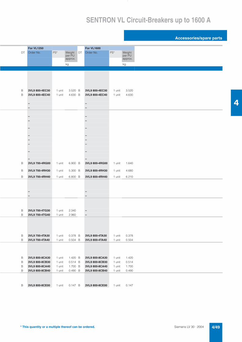
Siemens LV 30 · 2004 4/49
SENTRON VL Circuit-Breakers up to 1600 A
Accessories/spare parts
4
For VL1250 For VL1600
DT Order No. PS* Weight per PU approx.
DT Order No. PS* Weight per PU approx.
kg kg
B 3VL9 800-4EC30 1 unit 3.520 B 3VL9 800-4EC30 1 unit 3.520
B 3VL9 800-4EC40 1 unit 4.630 B 3VL9 800-4EC40 1 unit 4.630
– –
– –
– –
– –
– –
– –
– –
– –
– –
– –
B 3VL9 700-4RG00 1 unit 6.900 B 3VL9 800-4RG00 1 unit 1.640
B 3VL9 700-4RH30 1 unit 5.300 B 3VL9 800-4RH30 1 unit 4.680
B 3VL9 700-4RH40 1 unit 6.800 B 3VL9 800-4RH40 1 unit 6.210
– –
– –
B 3VL9 700-4TG30 1 unit 2.340 –
B 3VL9 700-4TG40 1 unit 2.960 –
B 3VL9 700-4TA30 1 unit 0.378 B 3VL9 800-4TA30 1 unit 0.378
B 3VL9 700-4TA40 1 unit 0.504 B 3VL9 800-4TA40 1 unit 0.504
B 3VL9 800-8CA30 1 unit 1.420 B 3VL9 800-8CA30 1 unit 1.420
B 3VL9 800-8CB30 1 unit 0.514 B 3VL9 800-8CB30 1 unit 0.514
B 3VL9 800-8CA40 1 unit 1.700 B 3VL9 800-8CA40 1 unit 1.700
B 3VL9 800-8CB40 1 unit 0.490 B 3VL9 800-8CB40 1 unit 0.490
B 3VL9 800-8CE00 1 unit 0.147 B 3VL9 800-8CE00 1 unit 0.147
* This quantity or a multiple thereof can be ordered.
Siemens LV 30 · 20044/50
SENTRON VL Circuit-Breakers up to 1600 A
Accessories/spare parts
4
1) Two interlocking modules and one Bowden wire are required. Cannot be used in conjunction with motorized operating mechanism.
2) Assembled safety lock in motorized operating mechanism, see Pages 4/40 to 4/43.
For VL160X For VL160
DT Order No. PS* Weight per PU approx.
DT Order No. PS* Weight per PU approx.
3- or 4-pole kg kg
InterlocksLocking device for toggle handlefor locking the circuit-breaker in the OFF position. Up to 3 padlocks with diameter from 5 to 8 mm can be used.Removable (padlocks not included)
B 3VL9 300-3HL00 1 unit 0.075 B 3VL9 300-3HL00 1 unit 0.075
Rear interlocking modulefor the mechanical interlocking of two adjacent circuit-breakers. The circuit-breakers must be of the same installation type and size. (mounting plate not within scope of supply)
Fixed-mounting circuit-breakers B 3VL9 300-8LC00 1 unit 0.386 B 3VL9 300-8LC00 1 unit 0.386
Plug-in/withdrawable circuit-breakers B 3VL9 300-8LD00 1 unit 0.436 B 3VL9 300-8LD00 1 unit 0.436
Interlocking module for Bowden wire interlocking1)for the mechanical interlocking of two circuit-breakers. Interlocking module for one circuit-breaker
Combinations of next size up/down possible (see Order No.)
B 3VL9 300-8LA00 1 unit 0.182 B 3VL9 300-8LA00 1 unit 0.182
Bowden wire for Bowden wire interlocking1)
Wire length 0.5 m B 3VL9 000-8LH10 1 unit 0.367 B 3VL9 000-8LH10 1 unit 0.367
Wire length 1.0 m B 3VL9 000-8LH20 1 unit 0.478 B 3VL9 000-8LH20 1 unit 0.478
Wire length 1.5 m B 3VL9 000-8LH30 1 unit 0.646 B 3VL9 000-8LH30 1 unit 0.646
Safety lock installation kits2)Key can be removed with the circuit-breaker in the OFF positionFor front-operated rotary operating mech-anisms
Lock types
Ronis B 3VL9 715-8HA00 1 unit 0.309 B 3VL9 715-8HA00 1 unit 0.309
CES B 3VL9 711-8HA00 1 unit 0.210 B 3VL9 711-8HA00 1 unit 0.210
For motorized operating mechanism with spring energy storeLock typesRonis – –
Filli Giussani B 3VL9 321-8HA00 1 unit 0.053 B 3VL9 321-8HA00 1 unit 0.053
Set of fixing screws (metric thread)including the screws, washers and nuts required to secure a 3- or 4-pole circuit-breaker to a prepared surface
Set with 4 screws B 3VL9 300-8SA40 1 unit 0.045 B 3VL9 300-8SA40 1 unit 0.045
Transparent cover for trip unit, sealableTo prevent access by unqualified person-nel and unauthorized changes to settings (seal not included) Electronic overcurrent trip unit – B 3VL9 700-8BL00 1 unit 0.011
Thermal-magnetic B 3VL9 300-8BM00 1 unit 0.052 B 3VL9 300-8BM00 1 unit 0.052
Manual tester for electronic trip units(battery-operated)for ETU/LCD ETU trip units, also interface with laptop or PC – 3VL9 000-8AK00 1 unit 0.660
Universal power supply(AC 50/60 Hz 120–240 V)Adapter unit – required if the battery power for the manual tester is not used
– B 3VL9 000-8AL00 1 unit 0.605
����������
����������
NS
E0_
0073
4
����������
���9��� �
* This quantity or a multiple thereof can be ordered.
Siemens LV 30 · 2004 4/51
SENTRON VL Circuit-Breakers up to 1600 A
Accessories/spare parts
4
For VL250 For VL400
DT Order No. PS* Weight per PU approx.
DT Order No. PS* Weight per PU approx.
kg kg
B 3VL9 300-3HL00 1 unit 0.075 B 3VL9 400-3HL00 1 unit 0.075
B 3VL9 300-8LC00 1 unit 0.386 B 3VL9 400-8LC00 1 unit 0.386
B 3VL9 300-8LD00 1 unit 0.436 B 3VL9 400-8LD00 1 unit 0.436
B 3VL9 300-8LA00 1 unit 0.182 B 3VL9 400-8LA00 1 unit 0.182
B 3VL9 000-8LH10 1 unit 0.367 –
B 3VL9 000-8LH20 1 unit 0.478 B 3VL9 000-8LH20 1 unit 0.478
B 3VL9 000-8LH30 1 unit 0.646 B 3VL9 000-8LH30 1 unit 0.646
B 3VL9 715-8HA00 1 unit 0.309 B 3VL9 715-8HA00 1 unit 0.309
B 3VL9 711-8HA00 1 unit 0.210 B 3VL9 711-8HA00 1 unit 0.210
– B 3VL9 715-8HA00 1 unit 0.309
B 3VL9 321-8HA00 1 unit 0.053 –
B 3VL9 300-8SA40 1 unit 0.045 B 3VL9 500-8SA40 1 unit 0.096
B 3VL9 700-8BL00 1 unit 0.011 B 3VL9 700-8BL00 1 unit 0.011
B 3VL9 300-8BM00 1 unit 0.052 B 3VL9 400-8BM00 1 unit 0.052
B 3VL9 000-8AK00 1 unit 0.660 B 3VL9 000-8AK00 1 unit 0.660
B 3VL9 000-8AL00 1 unit 0.605 B 3VL9 000-8AL00 1 unit 0.605
* This quantity or a multiple thereof can be ordered.
Siemens LV 30 · 20044/52
SENTRON VL Circuit-Breakers up to 1600 A
Accessories/spare parts
4
1) Two interlocking modules and one Bowden wire are required. Cannot be used in conjunction with motorized operating mechanism.
2) Assembled safety lock in motorized operating mechanism, see Pages 4/40 to 4/43.
For VL630 For VL800
DT Order No. PS* Weight per PU approx.
DT Order No. PS* Weight per PU approx.
3- or 4-pole kg kg
InterlocksLocking device for toggle handlefor locking the circuit-breaker in the OFF position. Up to 3 padlocks with diameter from 5 to 8 mm can be used.Removable (padlocks not included)
B 3VL9 600-3HL00 1 unit 0.184 B 3VL9 600-3HL00 1 unit 0.184
Rear interlocking modulefor the mechanical interlocking of two adjacent circuit-breakers. The circuit-breakers must be of the same installation type and size.
Fixed-mounting circuit-breakers B 3VL9 600-8LC00 1 unit 1.900 B 3VL9 600-8LC00 1 unit 1.900
Plug-in/withdrawable circuit-breakers B 3VL9 600-8LD00 1 unit 5.070 B 3VL9 600-8LD00 1 unit 5.070
Interlocking module for Bowden wire interlocking1)for the mechanical interlocking of two circuit-breakers. Interlocking module for one circuit-breaker
Combinations of next size up/down possible (see Order No.)
B 3VL9 600-8LA00 1 unit 0.256 B 3VL9 600-8LA00 1 unit 0.256
Bowden wire for Bowden wire interlocking1)
Wire length 0.5 m – –
Wire length 1.0 m B 3VL9 000-8LH20 1 unit 0.478 B 3VL9 000-8LH20 1 unit 0.478
Wire length 1.5 m B 3VL9 000-8LH30 1 unit 0.646 B 3VL9 000-8LH30 1 unit 0.646
Safety lock installation kits2)Key can be removed with the circuit-breaker in the OFF positionFor front-operated rotary operating mech-anisms
Lock types
Ronis B 3VL9 715-8HA00 1 unit 0.309 B 3VL9 715-8HA00 1 unit 0.309
CES B 3VL9 711-8HA00 1 unit 0.210 B 3VL9 711-8HA00 1 unit 0.210
For motorized operating mechanism with spring energy storeLock typesRonis B 3VL9 715-8HA00 1 unit 0.309 B 3VL9 715-8HA00 1 unit 0.309
Filli Giussani – –
Set of fixing screws (metric thread)including the screws, washers and nuts required to secure a 3 or 4-pole circuit-breaker to a prepared surface
Set with 4 screws B 3VL9 500-8SA40 1 unit 0.096 B 3VL9 600-8SA40 1 unit 0.107
Transparent cover for trip unit, sealableTo prevent access by unqualified person-nel and unauthorized changes to settings (seal not included) Electronic overcurrent trip unit B 3VL9 700-8BL00 1 unit 0.011 B 3VL9 700-8BL00 1 unit 0.011
Thermal-magnetic B 3VL9 600-8BM00 1 unit 0.026 –
Manual tester for electronic trip units(battery-operated)for ETU/LCD ETU trip unit, also interface with laptop or PC B 3VL9 000-8AK00 1 unit 0.660 B 3VL9 000-8AK00 1 unit 0.660
Universal power supply(AC 50/60 Hz 120–240 V)Adapter unit – required if the battery power for the manual tester is not used
B 3VL9 000-8AL00 1 unit 0.605 B 3VL9 000-8AL00 1 unit 0.605
����������
����������
NS
E0_
0073
4
����������
���9��� �
* This quantity or a multiple thereof can be ordered.
Siemens LV 30 · 2004 4/53
SENTRON VL Circuit-Breakers up to 1600 A
Accessories/spare parts
4
For VL1250 For VL1600
DT Order No. PS* Weight per PU approx.
DT Order No. PS* Weight per PU approx.
kg kg
B 3VL9 800-3HL00 1 unit 0.240 B 3VL9 800-3HL00 1 unit 0.240
B 3VL9 800-8LC00 1 unit 2.930 B 3VL9 800-8LC00 1 unit 2.930
B 3VL9 800-8LD00 1 unit 3.820 B 3VL9 800-8LD00 1 unit 3.820
B 3VL9 800-8LA00 1 unit 0.287 B 3VL9 800-8LA00 1 unit 0.287
– –
– –
B 3VL9 000-8LH30 1 unit 0.646 B 3VL9 000-8LH30 1 unit 0.646
B 3VL9 715-8HA00 1 unit 0.309 B 3VL9 715-8HA00 1 unit 0.309
B 3VL9 711-8HA00 1 unit 0.210 B 3VL9 711-8HA00 1 unit 0.210
B 3VL9 715-8HA00 1 unit 0.309 B 3VL9 715-8HA00 1 unit 0.309
– –
B 3VL9 800-8SA40 1 unit 0.102 B 3VL9 800-8SA40 1 unit 0.102
B 3VL9 700-8BL00 1 unit 0.011 B 3VL9 700-8BL00 1 unit 0.011
– –
B 3VL9 000-8AK00 1 unit 0.660 B 3VL9 000-8AK00 1 unit 0.660
B 3VL9 000-8AL00 1 unit 0.605 B 3VL9 000-8AL00 1 unit 0.605
* This quantity or a multiple thereof can be ordered.
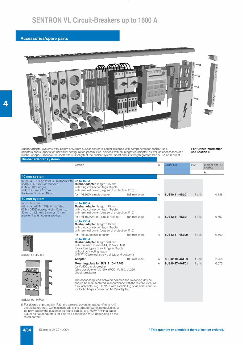
Siemens LV 30 · 20044/54
SENTRON VL Circuit-Breakers up to 1600 A
Accessories/spare parts
4
1) For degree of protection IP30, the terminal covers on pages 4/46 to 4/49 should be ordered. Connecting leads to the adapter/switching device must be provided by the customer as round cables, e.g. H07V-R with a cable lug, or as flat conductors for bolt-type connection M10, depending on the rated current.
Busbar adapter systems with 40 mm or 60 mm busbar center-to-center distance with components for busbar runs, adapters and supports for individual configuration possibilities, devices with an integrated adapter, as well as accessories andbusbar copper. Observe the short-circuit strength of the busbar system. Short-circuit strength greater than 50 kA on request.
For further information see Section 8.
Busbar adapter systems
Version DT Order No. PS* Weight per PU approx.
kg
40 mm systemto DIN 43870 Part 2 for Cu busbars with sharp (DIN 1759) or rounded (DIN 46 433) edges, width 12 mm or 15 mm, thickness 5 mm or 10 mm.
up to 160 ABusbar adapter, length 175 mm with plug connection tags, 3-pole with terminal cover (degree of protection IP10)1)
for 1 VL160X circuit-breaker 108 mm wide A 8US10 11–4SL01 1 unit 0.585
60 mm systemfor Cu busbars with sharp (DIN 1759) or rounded (DIN 46433) edges, width 12 mm to 30 mm, thickness 5 mm or 10 mm,also for T and I special profiles
up to 160 ABusbar adapter, length 175 mm with plug connection tags, 3-pole with terminal cover (degree of protection IP10)1)
for 1 VL160X/VL160 circuit-breaker 108 mm wide A 8US12 11–4SL01 1 unit 0.597
up to 250 ABusbar adapter, length 175 mm with plug connection tags, 3-pole with terminal cover (degree of protection IP10)1)
8US12 11–4SL00
for 1 VL250 circuit-breaker 108 mm wide A 8US12 11–4SL00 1 unit 0.662
up to 400 ABusbar adapter, length 320 mm with threaded inserts M 4, M 6 and M 8 for various types of switchgear, 3-pole without connecting leads, with M 10 terminal screws at top and bottom1)
8US12 10–4AF00
Adapter 185 mm wide A 8US12 10–4AF00 1 unit 2.760
Mounting plate for 8US12 10–4AF00for VL400 circuit-breaker(also possible for VL160X+RCD, VL160, VL250 circuit-breakers)
The connecting lead between adapter and switching device should be manufactured in accordance with the rated current as a round cable, e.g. H07V-R, with a cable lug or as a flat conduc-tor for bolt-type connection M 10 (adapter).
A 8US19 27–4AF01 1 unit 0.575
* This quantity or a multiple thereof can be ordered.
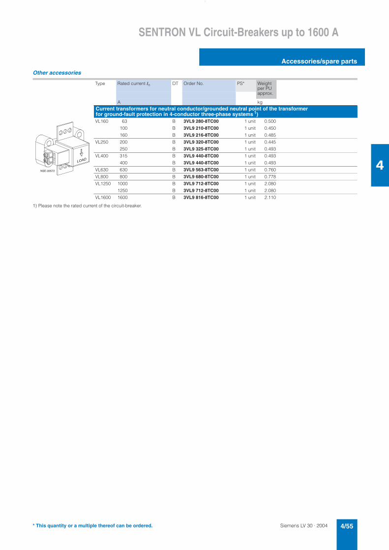
Siemens LV 30 · 2004 4/55
SENTRON VL Circuit-Breakers up to 1600 A
Accessories/spare parts
4
Other accessories
1) Please note the rated current of the circuit-breaker.
Type Rated current In DT Order No. PS* Weight per PU approx.
A kgCurrent transformers for neutral conductor/grounded neutral point of the transformer for ground-fault protection in 4-conductor three-phase systems 1)VL160 63 B 3VL9 280-8TC00 1 unit 0.500
100 B 3VL9 210-8TC00 1 unit 0.450
160 B 3VL9 216-8TC00 1 unit 0.485
VL250 200 B 3VL9 320-8TC00 1 unit 0.445
250 B 3VL9 325-8TC00 1 unit 0.493
VL400 315 B 3VL9 440-8TC00 1 unit 0.493
400 B 3VL9 440-8TC00 1 unit 0.493
VL630 630 B 3VL9 563-8TC00 1 unit 0.760
VL800 800 B 3VL9 680-8TC00 1 unit 0.778
VL1250 1000 B 3VL9 712-8TC00 1 unit 2.080
1250 B 3VL9 712-8TC00 1 unit 2.080
VL1600 1600 B 3VL9 816-8TC00 1 unit 2.110
NSE-00572
* This quantity or a multiple thereof can be ordered.

Siemens LV 30 · 20044/56
SENTRON VL Circuit-Breakers up to 1600 A
Accessories/spare parts
4
1) For withdrawable version IP20.
For VL160X For VL160
DT Order No. PS* Weight per PU approx.
DT Order No. PS* Weight per PU approx.
3- or 4-pole kg kg
Other accessoriesA Masking frame (cover frame)
for door cut-out
AIP40
Fixed-mounted or plug-in circuit-breaker B 3VL9 300-8BC00 1 unit 0.140 B 3VL9 300-8BC00 1 unit 0.140
BIP40
Circuit-breaker with front-operated rotary operating mechanism or motorized operating mechanism B 3VL9 300-8BG00 1 unit 0.099 B 3VL9 300-8BG00 1 unit 0.099
B CIP20
Withdrawable circuit-breaker with toggle lever actuation. Installation kit contains masking frame and extended escutcheon (cannot be used together with a motorized operating mechanism/rotary oper-ating mechanism)
– B 3VL9 300-8BH00 1 unit 0.267
DIP40
Fixed-mounted or plug-in circuit-breaker RCD switch masking frame B 3VL9 300-8BD00 1 unit 0.047 B 3VL9 300-8BD00 1 unit 0.047
C RCD masking frame B 3VL9 300-8BD00 1 unit 0.047 B 3VL9 300-8BD00 1 unit 0.047
E 1)IP40
Circuit-breaker with RCD module and front-operated rotary operating mechanism. Installation kit con-tains masking frame and extended escutcheon
– B 3VL9 300-8BH00 1 unit 0.267
D
Circuit-breaker with RCD module and motorized operating mechanism.Installation kit contains masking frame and extended escutcheon – B 3VL9 300-8BJ00 1 unit 1.040
Toggle lever extension – –
E
NSE-00574
���9��� �
�����
����
��
���9���
���9��� �
* This quantity or a multiple thereof can be ordered.
Siemens LV 30 · 2004 4/57
SENTRON VL Circuit-Breakers up to 1600 A
Accessories/spare parts
4
For VL250 For VL400
DT Order No. PS* Weight per PU approx.
DT Order No. PS* Weight per PU approx.
kg kg
B 3VL9 300-8BC00 1 unit 0.140 B 3VL9 400-8BC00 1 unit 0.057
B 3VL9 300-8BG00 1 unit 0.099 B 3VL9 400-8BG00 1 unit 0.145
B 3VL9 300-8BH00 1 unit 0.267 B 3VL9 400-8BH00 1 unit 0.267
B 3VL9 300-8BD00 1 unit 0.047 B 3VL9 400-8BC00 1 unit 0.057
B 3VL9 300-8BD00 1 unit 0.047 B 3VL9 400-8BD00 1 unit 0.047
B 3VL9 300-8BH00 1 unit 0.267 B 3VL9 400-8BH00 1 unit 0.267
B 3VL9 300-8BJ00 1 unit 1.040 B 3VL9 400-8BJ00 1 unit 1.040
– B 3VL9 400-3HN00 1 unit 0.038
* This quantity or a multiple thereof can be ordered.
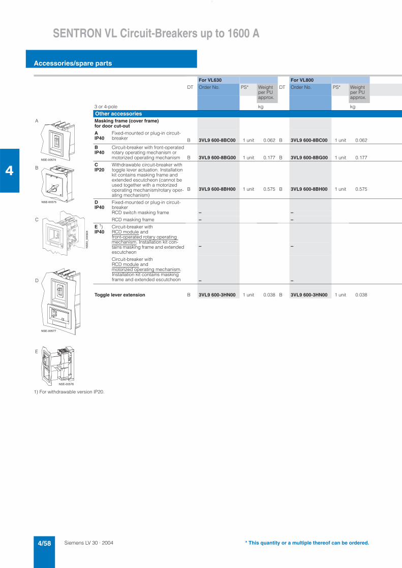
Siemens LV 30 · 20044/58
SENTRON VL Circuit-Breakers up to 1600 A
Accessories/spare parts
4
1) For withdrawable version IP20.
For VL630 For VL800
DT Order No. PS* Weight per PU approx.
DT Order No. PS* Weight per PU approx.
3 or 4-pole kg kg
Other accessoriesA Masking frame (cover frame)
for door cut-out
AIP40
Fixed-mounted or plug-in circuit-breaker B 3VL9 600-8BC00 1 unit 0.062 B 3VL9 600-8BC00 1 unit 0.062
BIP40
Circuit-breaker with front-operated rotary operating mechanism or motorized operating mechanism B 3VL9 600-8BG00 1 unit 0.177 B 3VL9 600-8BG00 1 unit 0.177
BCIP20
Withdrawable circuit-breaker with toggle lever actuation. Installation kit contains masking frame and extended escutcheon (cannot be used together with a motorized operating mechanism/rotary oper-ating mechanism)
B 3VL9 600-8BH00 1 unit 0.575 B 3VL9 600-8BH00 1 unit 0.575
DIP40
Fixed-mounted or plug-in circuit-breakerRCD switch masking frame – –
C RCD masking frame – –
E 1)IP40
Circuit-breaker with RCD module and front-operated rotary operating mechanism. Installation kit con-tains masking frame and extended escutcheon
– –
D
Circuit-breaker with RCD module and motorized operating mechanism.Installation kit contains masking frame and extended escutcheon – –
Toggle lever extension B 3VL9 600-3HN00 1 unit 0.038 B 3VL9 600-3HN00 1 unit 0.038
E
NSE-00574
���9��� �
�����
����
��
���9���
���9��� �
* This quantity or a multiple thereof can be ordered.
Siemens LV 30 · 2004 4/59
SENTRON VL Circuit-Breakers up to 1600 A
Accessories/spare parts
4
For VL1250 For VL1600
DT Order No. PS* Weight per PU approx.
DT Order No. PS* Weight per PU approx.
kg kg
B 3VL9 800-8BC00 1 unit 0.050 B 3VL9 800-8BC00 1 unit 0.050
B 3VL9 800-8BG00 1 unit 0.254 B 3VL9 800-8BG00 1 unit 0.254
B 3VL9 800-8BH00 1 unit 0.805 B 3VL9 800-8BH00 1 unit 0.805
– –– –
– –
– –
B 3VL9 800-3HN00 1 unit 0.244 B 3VL9 800-3HN00 1 unit 0.244
* This quantity or a multiple thereof can be ordered.
Siemens LV 30 · 20044/60
SENTRON VL Circuit-Breakers up to 1600 A
Project planning aids
4
■ Characteristics
Tripping characteristics
The indicated tripping values for the inverse-time delayed over-current trip units (thermal overload releases, "L" trip units) are mean values taken from the spread of all setting ranges from the cold state and under even load conditions on the conducting paths.
The tripping characteristics of the instantaneous (electromag-netic) short-circuit releases ("I" trip units) are based on the phase rated current In, which also represents the upper value of the setting range on circuit-breakers with adjustable thermal over-load release. With a lower operating current there is a corre-spondingly higher multiple for the tripping current of the "I" trip unit.
"L" thermal overload release
"I" instantaneous (electromagnetic) short-circuit release
SENTRON VL160 circuit-breakerTripping characteristic for system protection circuit-breaker, Icu 100 kA max. at 415 V; adjustable "I" trip unit
SENTRON VL160X circuit-breakerTripping characteristic for system protection circuit-breaker, Icu 70 kA max. at 415 V; "I" trip unit with fixed setting
SENTRON VL250 circuit-breakerTripping characteristic for system protection circuit-breaker, Icu 100 kA max. at 415 V; adjustable "I" trip unit
�
��
��
��
���
���
���
�����
��
����
����
�� ��� �� �� ��� ��� ��� �����������
���
�����
�����
�����
������
���
���
��
��
��
�
�
������ �
�������
������
�
��
��
��
���
���
���
�����
��
����
����
�� ��� �� �� ��� ��� ��� ������������
���
�����
�����
�����
������
���
���
��
��
��
�
�
��������
�������
������
�
��
��
��
���
���
���
�����
��
����
����
�� ��� �� �� ��� ��� ��� �����������
���
�����
�����
�����
������
���
���
��
��
��
�
�
��������
�������
������
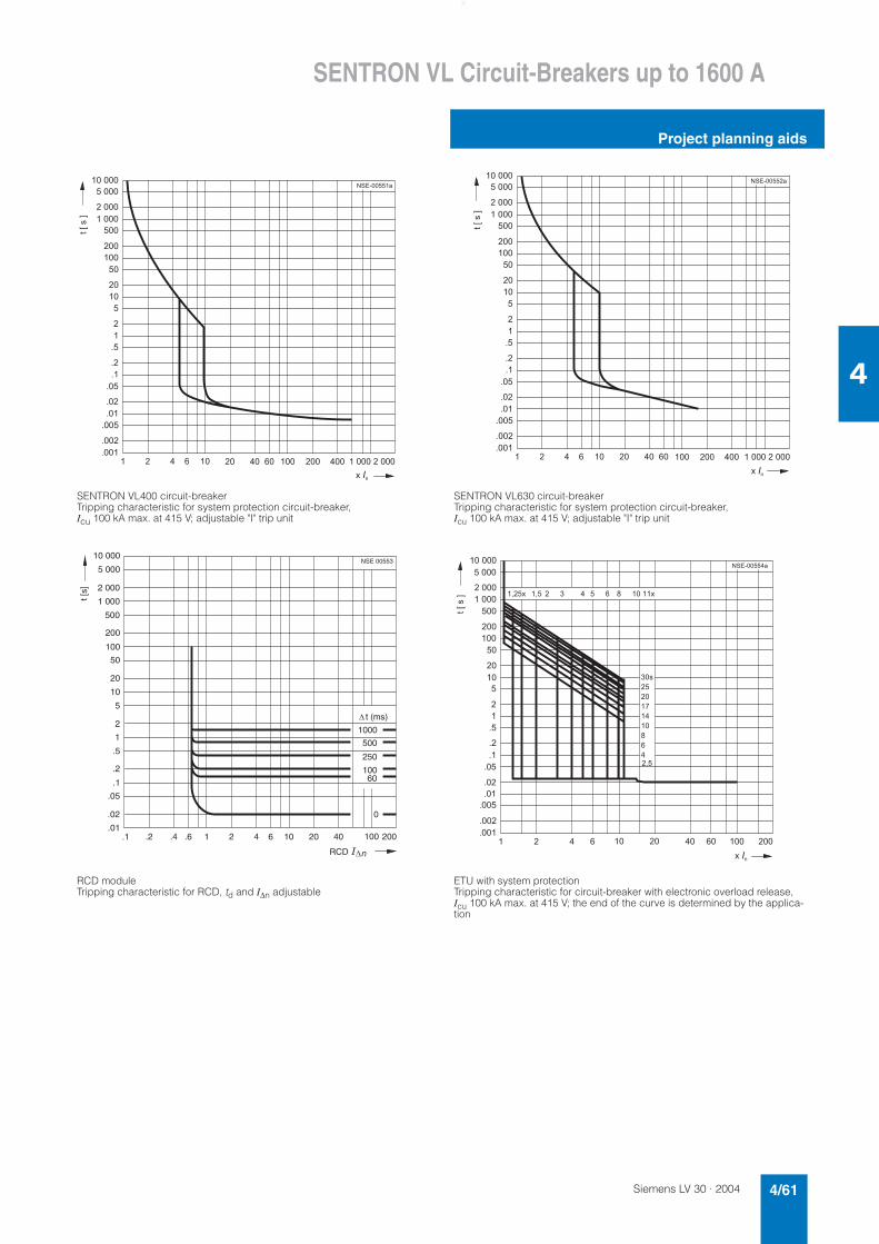
Siemens LV 30 · 2004 4/61
SENTRON VL Circuit-Breakers up to 1600 A
Project planning aids
4
SENTRON VL400 circuit-breakerTripping characteristic for system protection circuit-breaker, Icu 100 kA max. at 415 V; adjustable "I" trip unit
SENTRON VL630 circuit-breakerTripping characteristic for system protection circuit-breaker, Icu 100 kA max. at 415 V; adjustable "I" trip unit
RCD module Tripping characteristic for RCD, td and I∆n adjustable
ETU with system protection Tripping characteristic for circuit-breaker with electronic overload release,Icu 100 kA max. at 415 V; the end of the curve is determined by the applica-tion
�
��
��
��
���
���
���
�����
��
����
����
�� ��� �� �� ��� ��� ��� �����������
���
�����
�����
�����
������
���
���
��
��
��
�
�
��������
�������
�����
�
��
��
��
���
���
���
�����
��
����
����
�� ��� �� �� ��� ��� ��� �����������
���
�����
�����
�����
������
���
���
��
��
��
�
�
��������
�������
������
10
2
5
1
.5
.1
.2
.01.1
2
.02
.05
.4.2 1.6 4 6 10 20 40 200
5 000
10 000
2 000
1 000
100
200
500
20
50
NSE 00553
100
1000
500
250
10060
0
� t (ms)
�
t [s]
�nRCD
�
��
��
��
���
���
���
�����
��
����
����
�� ��� �� �� ��� ���
���
������
���
���
��
��
��
�
�
��������
�����
�����
�����
����� ��� � � � � � � ������
���
��
��
��
��
��
�
�
����
�������
������
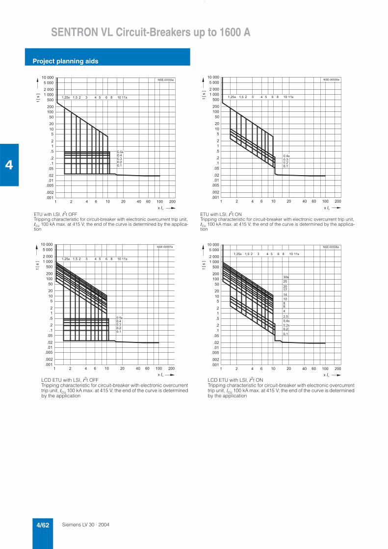
Siemens LV 30 · 20044/62
SENTRON VL Circuit-Breakers up to 1600 A
Project planning aids
4
ETU with LSI, I2t OFF Tripping characteristic for circuit-breaker with electronic overcurrent trip unit,Icu 100 kA max. at 415 V; the end of the curve is determined by the applica-tion
ETU with LSI, I2t ON Tripping characteristic for circuit-breaker with electronic overcurrent trip unit,Icu 100 kA max. at 415 V; the end of the curve is determined by the applica-tion
LCD ETU with LSI, I2t OFF Tripping characteristic for circuit-breaker with electronic overcurrent trip unit, Icu 100 kA max. at 415 V; the end of the curve is determined by the application
LCD ETU with LSI, I2t ON Tripping characteristic for circuit-breaker with electronic overcurrent trip unit, Icu 100 kA max. at 415 V; the end of the curve is determined by the application
�
��
��
��
���
���
���
�����
��
����
����
�� ��� �� �� ��� ���
���
������
���
���
��
��
��
�
�
��������
�����
�����
�����
����� ��� � � � � � � ������
����������������
�������
�����
�
��
��
��
���
���
���
�����
��
����
����
�� ��� �� �� ��� ���
���
������
���
���
��
��
��
�
�
��������
�����
�����
�����
����� ��� � � � � � � ������
�������������
�������
������
�
��
��
��
���
���
���
�����
��
����
����
�� ��� �� �� ��� ���
���
������
���
���
��
��
��
�
�
��������
�����
�����
�����
����� ��� � � � � � � ������
����������������
�������
�����
�
��
��
��
���
���
���
�����
��
����
����
�� ��� �� �� ��� ���
���
������
���
���
��
��
��
�
�
��������
�����
�����
���������� ��� � � � � � � ������
���
��
����
��
��
��
�
���
����
�������
���
�������
������
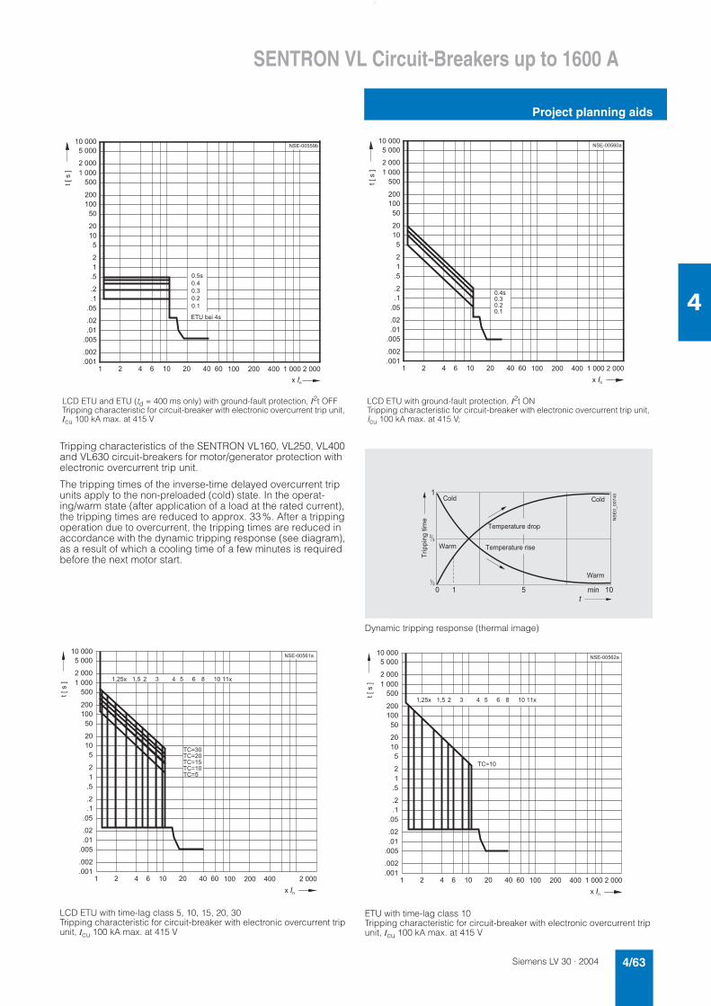
Siemens LV 30 · 2004 4/63
SENTRON VL Circuit-Breakers up to 1600 A
Project planning aids
4
Tripping characteristics of the SENTRON VL160, VL250, VL400 and VL630 circuit-breakers for motor/generator protection with electronic overcurrent trip unit.
The tripping times of the inverse-time delayed overcurrent trip units apply to the non-preloaded (cold) state. In the operat-ing/warm state (after application of a load at the rated current), the tripping times are reduced to approx. 33%. After a tripping operation due to overcurrent, the tripping times are reduced in accordance with the dynamic tripping response (see diagram), as a result of which a cooling time of a few minutes is required before the next motor start.
LCD ETU with time-lag class 5, 10, 15, 20, 30 Tripping characteristic for circuit-breaker with electronic overcurrent trip unit, Icu 100 kA max. at 415 V
Dynamic tripping response (thermal image)
ETU with time-lag class 10 Tripping characteristic for circuit-breaker with electronic overcurrent trip unit, Icu 100 kA max. at 415 V
LCD ETU and ETU (td = 400 ms only) with ground-fault protection, I2t OFF Tripping characteristic for circuit-breaker with electronic overcurrent trip unit, Icu 100 kA max. at 415 V
LCD ETU with ground-fault protection, I2t ON Tripping characteristic for circuit-breaker with electronic overcurrent trip unit, Icu 100 kA max. at 415 V;
�
��
��
��
���
���
���
�����
��
����
����
�� ��� �� �� ��� ��� ��� �����������
���
�����
�����
�����
������
���
���
��
��
��
�
�
������ �
����
���
���
���
���
�������
����������
����
�
��
��
��
���
���
���
�����
��
����
����
�� ��� �� �� ��� ��� ��� �����������
���
�����
�����
�����
������
���
���
��
��
��
�
�
��������
�������������
�������
������
�
��
��
��
���
���
���
�����
��
����
����
�� ��� �� �� ��� ��� ��� �����
���
�����
�����
�����
������
���
���
��
��
��
�
�
��������
����� ��� � � � � � � ������
������������������������
�������
������
�
��
��
� � � �� ��
�
��!�����
�"�##��$��� �
�� #�"��%"��&"'#
�� #�"��%"��"���
�'(&
)�"
�'(&
)�"
�
��
��
��
���
���
���
�����
��
����
����
�� ��� �� �� ��� ��� ��� �����������
���
�����
�����
�����
������
���
���
��
��
��
�
�
��������
����� ��� � � � � � � ������
�����
�������
������
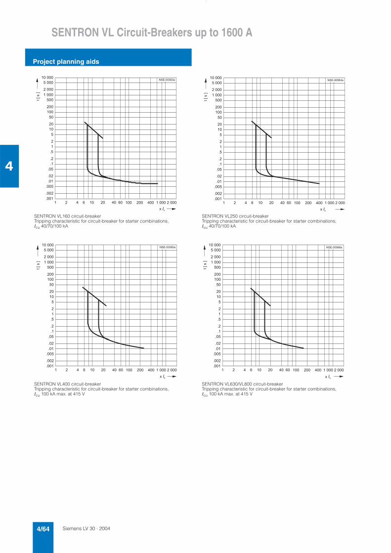
Siemens LV 30 · 20044/64
SENTRON VL Circuit-Breakers up to 1600 A
Project planning aids
4
SENTRON VL160 circuit-breakerTripping characteristic for circuit-breaker for starter combinations, Icu 40/70/100 kA
SENTRON VL250 circuit-breakerTripping characteristic for circuit-breaker for starter combinations, Icu 40/70/100 kA
SENTRON VL400 circuit-breakerTripping characteristic for circuit-breaker for starter combinations, Icu 100 kA max. at 415 V
SENTRON VL630/VL800 circuit-breakerTripping characteristic for circuit-breaker for starter combinations, Icu 100 kA max. at 415 V
�
��
��
��
���
���
���
�����
��
����
����
�� ��� �� �� ��� ��� ��� �����������
���
�����
�����
�����
������
���
���
��
��
��
�
�
��������
�������
�����
�
��
��
��
���
���
���
�����
��
����
����
�� ��� �� �� ��� ��� ��� �����������
���
�����
�����
�����
������
���
���
��
��
��
�
�
��������
�������
�������
�
��
��
��
���
���
���
�����
��
����
����
�� ��� �� �� ��� ��� ��� �����������
���
�����
�����
�����
������
���
���
��
��
��
�
�
��������
�������
�����
�
��
��
��
���
���
���
�����
��
����
����
�� ��� �� �� ��� ��� ��� �����������
���
�����
�����
�����
������
���
���
��
��
��
�
�
��������
�������
�����
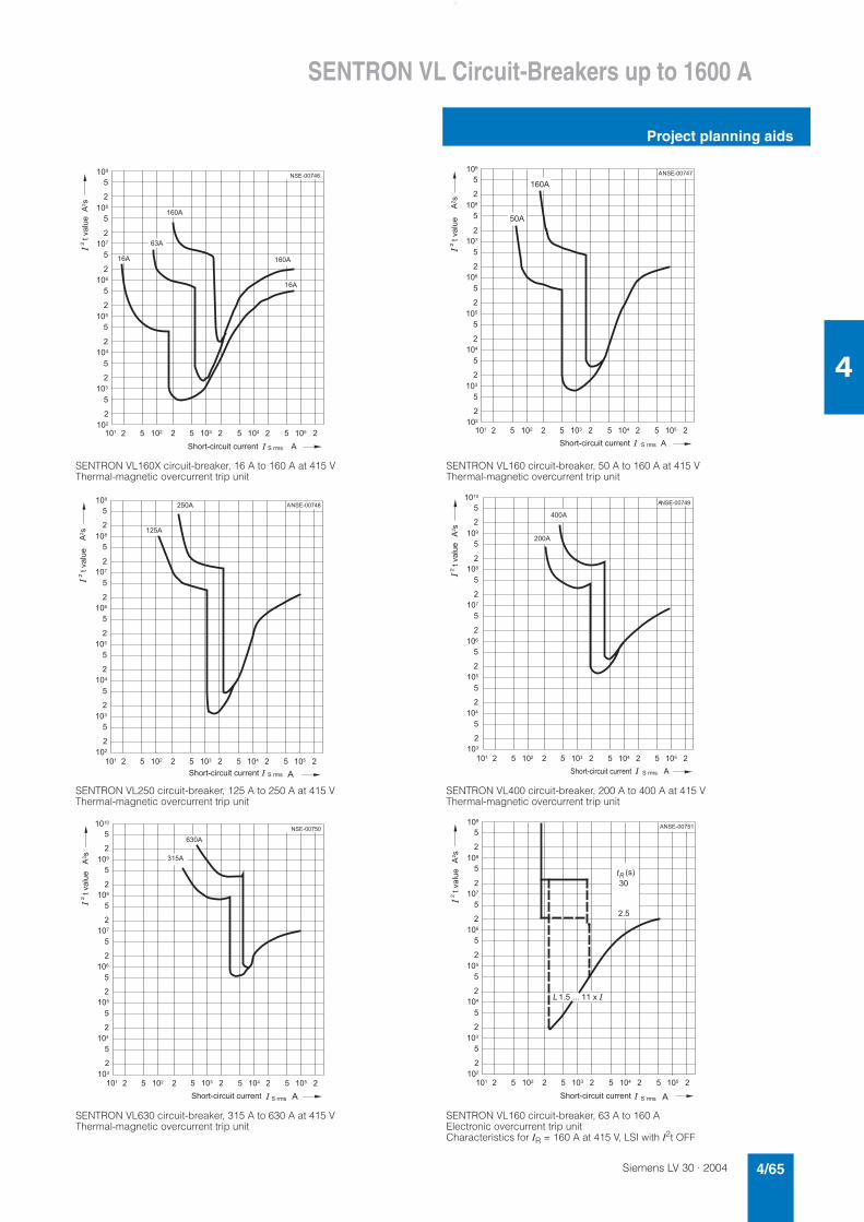
Siemens LV 30 · 2004 4/65
SENTRON VL Circuit-Breakers up to 1600 A
Project planning aids
4
SENTRON VL160X circuit-breaker, 16 A to 160 A at 415 V Thermal-magnetic overcurrent trip unit
SENTRON VL160 circuit-breaker, 50 A to 160 A at 415 V Thermal-magnetic overcurrent trip unit
SENTRON VL250 circuit-breaker, 125 A to 250 A at 415 V Thermal-magnetic overcurrent trip unit
SENTRON VL400 circuit-breaker, 200 A to 400 A at 415 V Thermal-magnetic overcurrent trip unit
SENTRON VL630 circuit-breaker, 315 A to 630 A at 415 V Thermal-magnetic overcurrent trip unit
SENTRON VL160 circuit-breaker, 63 A to 160 A Electronic overcurrent trip unit Characteristics for IR = 160 A at 415 V, LSI with I2t OFF
�������
���*
��*
��* ���*
��*
���
�
���
�
����
���
�
�
�
�
�
�
���
��
�
���
����
�
�
�
���� �� ���� ��� � � ��� � � ��� �
*��
*+'"��,�",%���,%""���
���-�(%�
�" �
���
�
�
���
�
����
���
���
�
�
�
�� ���� ��� �
�
�
�
���
��
�
���
����
�
�
�
� ��� � � ��� �
�������
���*
��*
*��
*+'"��,�",%���,%""������-�(%�
�" �
*
���
�
���
�
����
���
�
�
�
�
�
�
���
��
�
���
����
�
�
�
�������
���� �� ���� ��� � � ��� � � ��� �
���*
���*
*��
*+'"��,�",%���,%""���
���-�(%�
�" �
*
���
�
���
�
����
���
�
�
�
�
�
�
��
����
�
���
����
�
�
�
������
���� �� ���� ��� � � ��� � � ��� �
���*
���*
*��
*+'"��,�",%���,%""���
���-�(%�
�" �
*
���
�
���
�
����
���
�
�
�
�
�
�
��
����
�
���
����
�
�
�
�������
���� �� ���� ��� � � ��� � � ��� �
���*
���**��
*+'"��,�",%���,%""���
���-�(%�
�" ��
���
�
���
�
����
���
�
�
�
�
�
�
���
��
�
���
����
�
�
�
*��
�������
���� �� ���� ��� �
*
� ��� � � ��� �
�� .�/��
���
� ��������������
+'"��,�",%���,%""���
���-�(%�
�" �
*
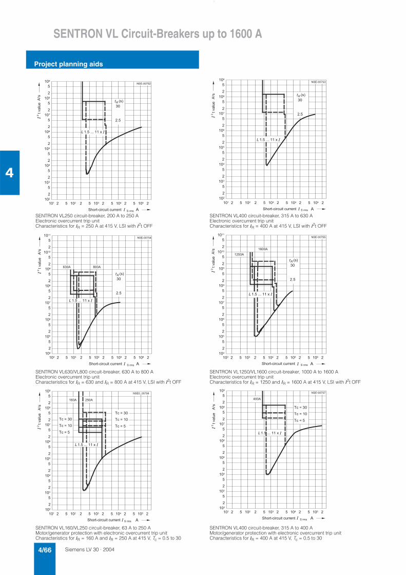
Siemens LV 30 · 20044/66
SENTRON VL Circuit-Breakers up to 1600 A
Project planning aids
4
SENTRON VL250 circuit-breaker, 200 A to 250 A Electronic overcurrent trip unit Characteristics for IR = 250 A at 415 V, LSI with I2t OFF
SENTRON VL400 circuit-breaker, 315 A to 630 A Electronic overcurrent trip unit Characteristics for IR = 400 A at 415 V, LSI with I2t OFF
SENTRON VL630/VL800 circuit-breaker, 630 A to 800 A Electronic overcurrent trip unit Characteristics for IR = 630 and IR = 800 A at 415 V, LSI with I2t OFF
SENTRON VL1250/VL1600 circuit-breaker, 1000 A to 1600 A Electronic overcurrent trip unit Characteristics for IR = 1250 and IR = 1600 A at 415 V, LSI with I2t OFF
SENTRON VL160/VL250 circuit-breaker, 63 A to 250 A Motor/generator protection with electronic overcurrent trip unit Characteristics for IR = 160 A and IR = 250 A at 415 V, Tc = 0.5 to 30
SENTRON VL400 circuit-breaker, 315 A to 400 A Motor/generator protection with electronic overcurrent trip unit Characteristics for IR = 400 A at 415 V, Tc = 0.5 to 30
���
�
���
�
����
���
�
�
�
�
�
�
���
��
�
���
����
�
�
�
*��
�������
���� �� ���� ��� �
*
� ��� � � ��� �
�� .�/��
���
� ��������������
+'"��,�",%���,%""���
���-�(%�
�" �
���
�
���
�
����
���
�
�
�
�
�
�
���
��
�
���
����
�
�
�
*��
�������
���� �� ���� ��� �
*
� ��� � � ��� �
�� .�/��
���
� ��������������
+'"��,�",%���,%""������-�(%�
�" �
���
�
���
�
����
���
�
�
�
�
�
�
����
����
�
��
����
�
�
�
*��
�������
���� �� ���� ��� �
*
� ��� � � ��� �
���* ���*
�� .�/��
���
� ��������������
+'"��,�",%���,%""���
���-�(%�
�" �
���
�
���
�
����
���
�
�
�
�
�
�
����
����
�
��
����
�
�
�
*��
�������
���� �� ���� ��� �
*
� ��� � � ��� �
����*
����*
�� .�/��
���
� ��������������
+'"��,�",%���,%""���
���-�(%�
�" �
���
�
���
�
����
���
�
�
�
�
�
�
���
��
�
���
����
�
�
�
*��
��!�����
���� �� ���� ��� �
*
� ��� � � ��� �
���* ���*
�,�����
� ��������������
�,�����
�,����
�,�����
�,�����
�,����
+'"��,�",%���,%""���
���-�(%�
�" ��
���
�
���
�
����
���
�
�
�
�
�
�
���
��
�
���
����
�
�
�
*��
�������
���� �� ���� ��� �
*
� ��� � � ��� �
���*
�,�����
� ��������������
�,�����
�,����
+'"��,�",%���,%""���
���-�(%�
�" �
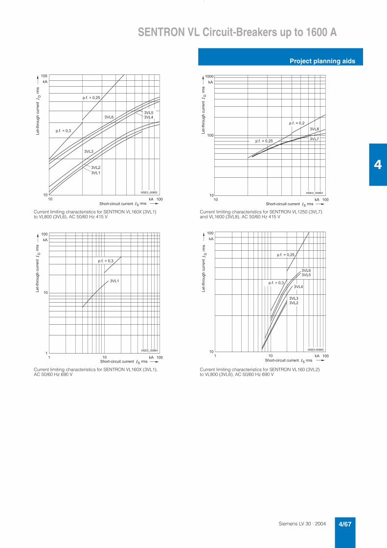
Siemens LV 30 · 2004 4/67
SENTRON VL Circuit-Breakers up to 1600 A
Project planning aids
4
Current limiting characteristics for SENTRON VL160X (3VL1) to VL800 (3VL6), AC 50/60 Hz 415 V
Current limiting characteristics for SENTRON VL1250 (3VL7) and VL1600 (3VL8), AC 50/60 Hz 415 V
Current limiting characteristics for SENTRON VL160X (3VL1), AC 50/60 Hz 690 V
Current limiting characteristics for SENTRON VL160 (3VL2) to VL800 (3VL6), AC 50/60 Hz 690 V
��
���
��!�����
�� 0* ���
0*
�12�
�12�
�12�
�12�
�12��12�
+'"��,�",%���,%""��� " �
2����+"'%$+�,%""���3" �
#�4��������
#�4�������
��
����
��!�����
�� 0* ���
0*
����12�
�12�
3" �
+'"��,�",%���,%""��� " �
#�4��������
#�4�������
2����+"'%$+�,%""���
�
���
��!�����
� 0* �����
0*
��
�12�
3" �
+'"��,�",%���,%""��� " �
#�4�������
2����+"'%$+�,%""���
��
���
��������
� 0* �����
0*
�12�
�12�
�12��12�
�12�
+'"��,�",%���,%""��� " �
3" �
#�4��������
#�4�������
2����+"'%$+�,%""���
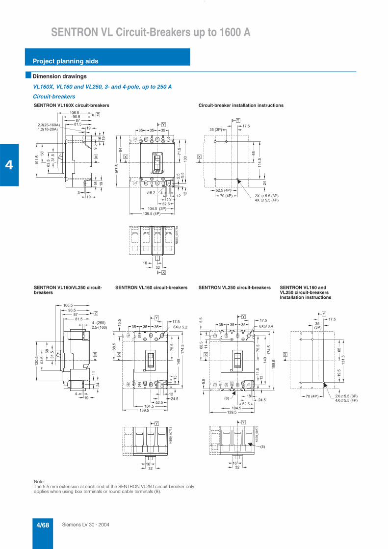
Siemens LV 30 · 20044/68
SENTRON VL Circuit-Breakers up to 1600 A
Project planning aids
4
■ Dimension drawings
VL160X, VL160 and VL250, 3- and 4-pole, up to 250 A
Circuit-breakers
SENTRON VL160X circuit-breakers Circuit-breaker installation instructions
SENTRON VL160/VL250 circuit-breakers
SENTRON VL160 circuit-breakers SENTRON VL250 circuit-breakers SENTRON VL160 and VL250 circuit-breakersInstallation instructions
Note:The 5.5 mm extension at each end of the SENTRON VL250 circuit-breaker only applies when using box terminals or round cable terminals (8).
�
�
�
�
�
�
� � � � � � � � �
� � � � � � � � � �
���
� ��� ���
����
� � � � � � �
� �
�
���
� � � � � � � � � �
� � � � � � � � �
�
� � � � �
� � � � �
� � �
� � � �
�
�
���
�
�
�����
�
� � � � � � � �
� �
� �
� �
����
� ���
� �
� � � �
�
����
�
� �
� � � � � �
� � � �
���
��
����
� � �
� � �
� � � �
�
� �
��������� �
� � �
� � � � � � � �
�
�
�
�����
����
�
�
����
� � � � �
� � � � �
� � �
� � � �
� � � �
���
�
� � � �
� � � � �
� � � � � � � �
� � � � � � � �
�����
����
� �
���
�
� � � �
��
� �
� � � �
� � �
�����
�����
�
�
� � � � � �
����������
� � �
�
� � �
�
�
� � � � � � � � �
� � � � � � � � � �
�
� � � �
� � � � �
����
�����
����
� � � � � �
�����
���
� � � �
�
�
� � � � �
���
� � �
�����
� � �
�����
� �
� �
���
����
� � � �
���
� � � � � �� �
�
�
�
���������
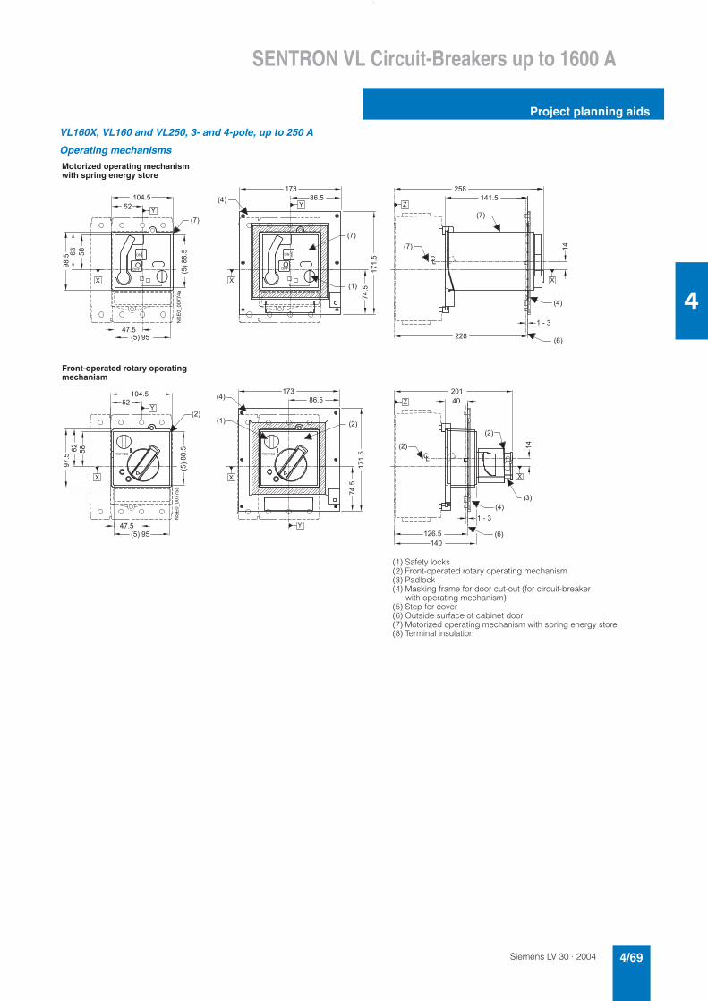
Siemens LV 30 · 2004 4/69
SENTRON VL Circuit-Breakers up to 1600 A
Project planning aids
4
VL160X, VL160 and VL250, 3- and 4-pole, up to 250 A
Operating mechanisms
Motorized operating mechanism with spring energy store
Front-operated rotary operating mechanism
(1) Safety locks(2) Front-operated rotary operating mechanism(3) Padlock(4) Masking frame for door cut-out (for circuit-breaker with operating mechanism)(5) Step for cover(6) Outside surface of cabinet door(7) Motorized operating mechanism with spring energy store (8) Terminal insulation
� � �
�
� � �
� � �
�
�
� � �
� � �
� �
��
� � �
� � �
� � �
��
���
�����
� � � � �
� � �
� � � � �
� � � � � � �
���������
� � �
��
� � � �
� �
�� � � �
�� �
�� � � �
�
�
�
�
�����������
�
� � � �
� ��
����
� � �
� � �
� � �
� � �
� �
� � �
� � �
��
� �
� � �
� � �
����� ���
���
� � � � �
� � � � � � �
� � �
� � � � �
���������
� � � �
� �
��
� � � �
� �
�
� � � !
� �
� � � !
�
�
�
�����������
�
� � � �
� ��
����
� �
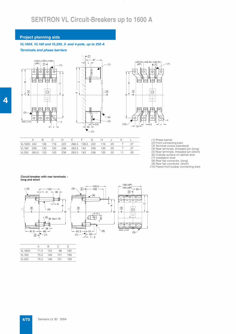
Siemens LV 30 · 20044/70
SENTRON VL Circuit-Breakers up to 1600 A
Project planning aids
4
VL160X, VL160 and VL250, 3- and 4-pole, up to 250 A
Terminals and phase barriers
A B C D E F G H J K L (1) Phase barrier(2) Front connecting bars(3) Terminal covers (standard)(4) Rear terminals, threaded pin (long)(5) Rear terminals, threaded pin (short)(6) Outside surface of cabinet door(7) Installation level(8) Rear flat connector, (long)(9) Rear flat connector, (short)
(10) Flared front busbar connecting bars
VL160X 242 126 116 222 266.5 138.5 222 116 20 7 27
VL160 258 130 120 238 283.5 143 238 120 20 7 27
VL250 263.5 133 120 238 283.5 143 238 120 22 11 29
� � �
� �
� � �
� � �
� � �
� � �
� �� �
� � �
�
"
�
� �
� � �
� �
�!
�
�
� � � �
� �
� � �
� � �
#
$
� � � � �
�
� �
�
�
�
� � � �
� � ��
�
� � � � � � � %
& �
&
%
� � � � �
Circuit-breaker with rear terminals – long and short
NSE0_0124966
123
A
81.5
4A
C
B DB
25.5
1 - 3
5181.5
11
63
38
120.5108
6
38
139 (4P) 104 (3P) 52
1 - 3
(7)
(3)
(4)
(9)
(5)
(7)(3)
(8)
(3)X
Z
Z
X X X
M 12x1.75
A B C D
VL160X 71.5 133 96 182
VL160 75.5 149 101 199
VL250 75.5 149 101 199
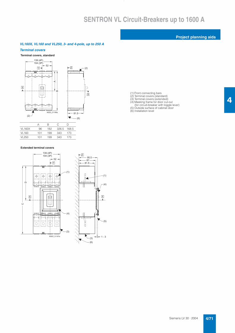
Siemens LV 30 · 2004 4/71
SENTRON VL Circuit-Breakers up to 1600 A
Project planning aids
4
VL160X, VL160 and VL250, 3- and 4-pole, up to 250 A
Terminal covers
Terminal covers, standard
(1) Front connecting bars(2) Terminal covers (standard)(3) Terminal covers (extended)(4) Masking frame for door cut-out (for circuit-breaker with toggle lever)(5) Outside surface of cabinet door(6) Installation level
� � �
� � �
� � �
� � � �
� � � � �
� � � � �
� � �
"
�
�
�
� � � � � � � � �
�
�
A B C D
VL160X 96 182 326.5 168.5
VL160 101 199 343 173
VL250 101 199 343 173
Extended terminal covers
� �
� � �
� �
� �
� � �
� � �
� � �
� �
!
�
� � �
� � � �
� � � � �
� � � � �
� � �
� � � �
� � � � �
�
� �
�
� � � � � � � � �
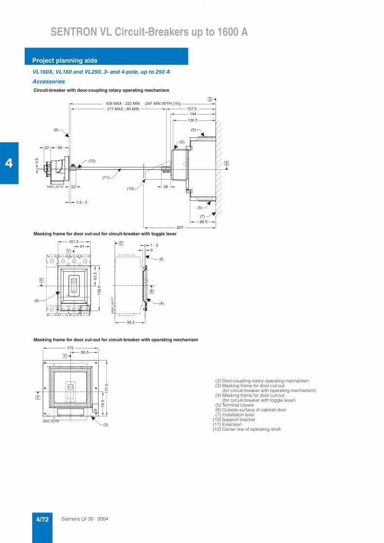
Siemens LV 30 · 20044/72
SENTRON VL Circuit-Breakers up to 1600 A
Project planning aids
4
VL160X, VL160 and VL250, 3- and 4-pole, up to 250 A
Accessories
Circuit-breaker with door-coupling rotary operating mechanism
Masking frame for door cut-out for circuit-breaker with toggle lever
Masking frame for door cut-out for circuit-breaker with operating mechanism
(2) Door-coupling rotary operating mechanism(3) Masking frame for door cut-out
(for circuit-breaker with operating mechanism)(4) Masking frame for door cut-out
(for circuit-breaker with toggle lever)(5) Terminal covers(6) Outside surface of cabinet door(7) Installation level
(10) Support bracket(11) Extension(12) Center line of operating shaft
� � �
� � �
� � � � � �
� � �
� � � � � � � � � �
� � � � ' � � � � � � � � ' � �
����
� � �� � �
� �
� � � ' � � � � � � � � � ' � �
� � �
� � � �
� �
�
� � � � �
� � �
�
� � �
� �
� � �
� � � � ' � � � ( � � # � � � � �
� � � �
� � �
� � �
� � �
� � �
����
� ���
� � � �
� � � � �
� � � � �
� ��
�
�
�
����������
� �
� �
� � � � �
�����
� ���
�
�
� � � � � � � � � �
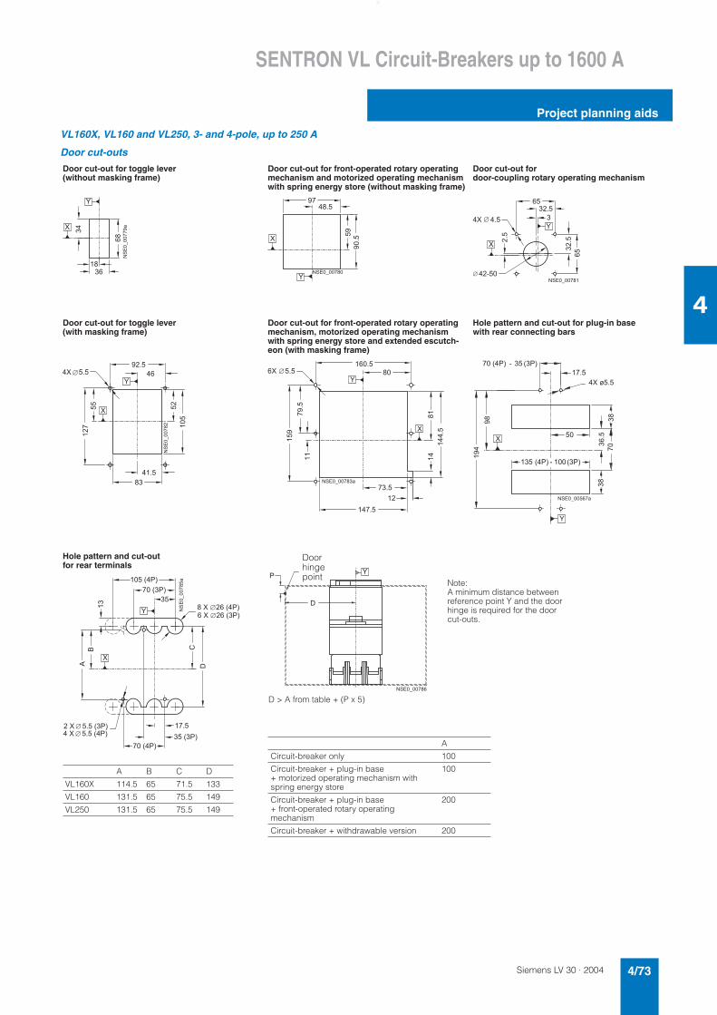
Siemens LV 30 · 2004 4/73
SENTRON VL Circuit-Breakers up to 1600 A
Project planning aids
4
VL160X, VL160 and VL250, 3- and 4-pole, up to 250 A
Door cut-outs
Door cut-out for toggle lever (without masking frame)
Door cut-out for front-operated rotary operating mechanism and motorized operating mechanism with spring energy store (without masking frame)
Door cut-out for door-coupling rotary operating mechanism
Door cut-out for toggle lever (with masking frame)
Door cut-out for front-operated rotary operating mechanism, motorized operating mechanism with spring energy store and extended escutch-eon (with masking frame)
Hole pattern and cut-out for plug-in base with rear connecting bars
Hole pattern and cut-out for rear terminals
�
�
�
� �
�
��
�����������
�
�
� � �
� � � � �
���
�����
� � � � � � � � � �
�
� � � �
� � � � � �
� �
����
� � �
����
���
�
� � � � � � � � �
�
�
� � ��
�
�
� � � �
� � �� � �
���
���
� �
� � � � �
���
���
����������
�� �
�
�
���
�����
�
� � �
� � � � �
�
� � � �
� � � � �
� �
����
� � �
� � � � � � � � � �
� �
�
�
�
� � � � � � � � � � � � �
��
� � � � � � � � � � � �
��
� �
� � �
�����
�
�
� � � � � � � � � � �
� � � ) � � �
�
!
� � � � � � � � � �
Doorhingepoint
Note:A minimum distance between reference point Y and the door hinge is required for the door cut-outs.
D > A from table + (P x 5)
A
Circuit-breaker only 100
Circuit-breaker + plug-in base + motorized operating mechanism with spring energy store
100
Circuit-breaker + plug-in base + front-operated rotary operating mechanism
200
Circuit-breaker + withdrawable version 200
�
�
"
�
�
� � � �
� � � � � �
�
� � � �
�
� � � � �
� � � � � �
!
� � � � � � � � � � � �
�����������
� � � � � � � � � � � � � �
� � � � � � � � � � � � � � �
� � � � � � � � � � � � �
A B C D
VL160X 114.5 65 71.5 133
VL160 131.5 65 75.5 149
VL250 131.5 65 75.5 149
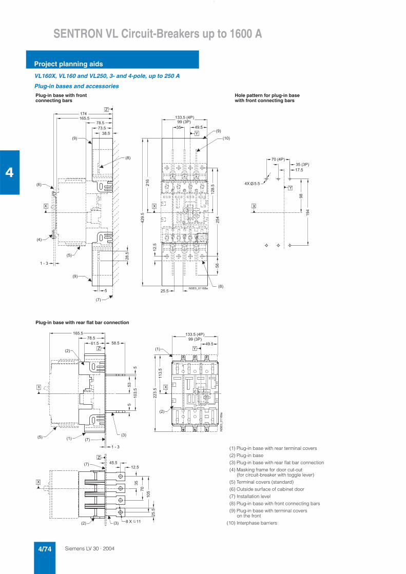
Siemens LV 30 · 20044/74
SENTRON VL Circuit-Breakers up to 1600 A
Project planning aids
4
VL160X, VL160 and VL250, 3- and 4-pole, up to 250 A
Plug-in bases and accessories
Plug-in base with front connecting bars
Hole pattern for plug-in base with front connecting bars
Plug-in base with rear flat bar connection
�
�
�
�
�
�
� � �
� � �
� � �
� � �
� � �
� � �
� � �
� � �
� � �
� � �
� � � � � �
� � � �
�
�����
� � �
� � � � �
� � � �
� � �
� � � � �
� � � �
������
����
� ��
� � � � � �
� � � � �
� � � � � �
��
����
�����
���
���
� � � �
� � � �
� � �� �
� � � � � � � � �
�
�
�
�
�
� � �
� � �
� � �� �
� � �
� � �
� �
� � �
� �
��
�
� � � � �
� � �
� � �
�����
������
��
���
��
�����
���
� � � � �
� � � � �
� � � � � � � �� � � �
� � � � � �
� � � � �
� � � � � � �
������ ���
�
� �
(1) Plug-in base with rear terminal covers
(2) Plug-in base
(3) Plug-in base with rear flat bar connection
(4) Masking frame for door cut-out (for circuit-breaker with toggle lever)
(5) Terminal covers (standard)
(6) Outside surface of cabinet door
(7) Installation level
(8) Plug-in base with front connecting bars
(9) Plug-in base with terminal covers on the front
(10) Interphase barriers
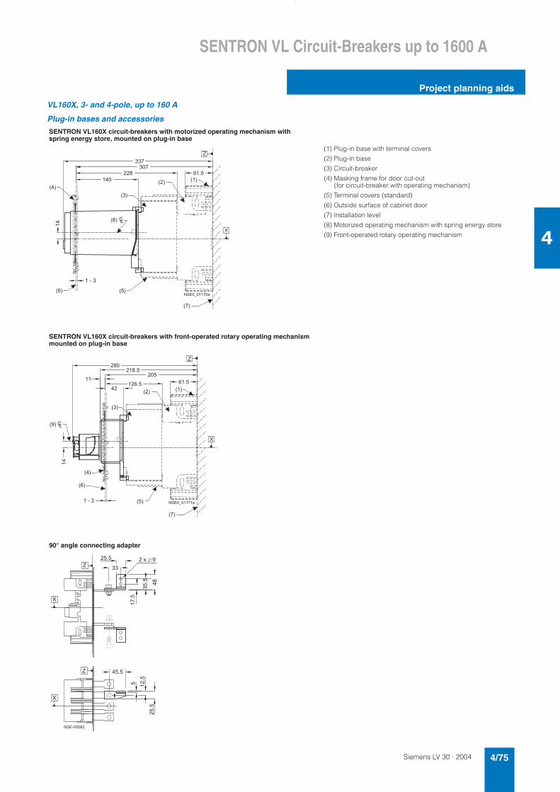
Siemens LV 30 · 2004 4/75
SENTRON VL Circuit-Breakers up to 1600 A
Project planning aids
4
VL160X, 3- and 4-pole, up to 160 A
Plug-in bases and accessories
SENTRON VL160X circuit-breakers with motorized operating mechanism with spring energy store, mounted on plug-in base
(1) Plug-in base with terminal covers
(2) Plug-in base
(3) Circuit-breaker
(4) Masking frame for door cut-out (for circuit-breaker with operating mechanism)
(5) Terminal covers (standard)
(6) Outside surface of cabinet door
(7) Installation level
(8) Motorized operating mechanism with spring energy store
(9) Front-operated rotary operating mechanism
SENTRON VL160X circuit-breakers with front-operated rotary operating mechanism mounted on plug-in base
90° angle connecting adapter
� � �
�
�
� � �
��
� � � � � �
� � �
� �
� � �
� �
��
� � � �
� � �
� � �
� �
�
� � � �
� � � � � � � � �
�
� � �
�
� � �
� � �
� � �
� � �
� � �
��
� �
� �
� � � �
��
�
� � � �
� � �
� � � � �
� � � � �
� � �
� � � �
� � � � � � � �
� ��
����
����
����
����
����
�
�������
�
�
�
���������
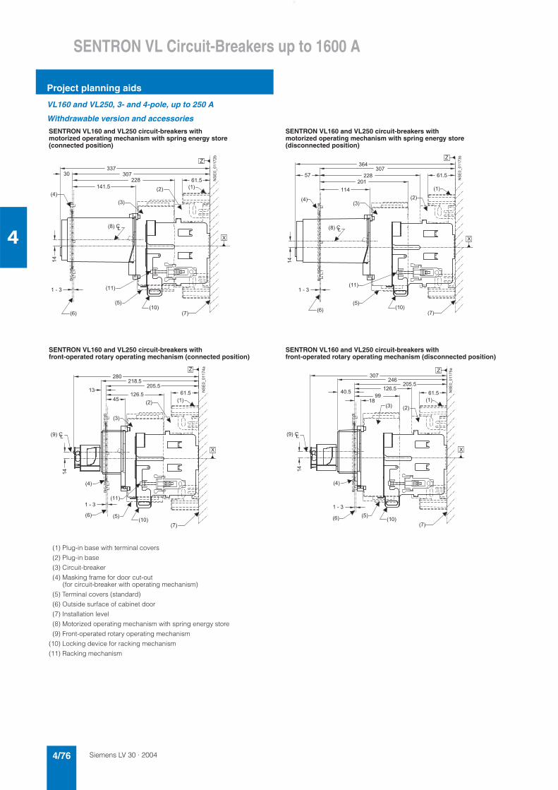
Siemens LV 30 · 20044/76
SENTRON VL Circuit-Breakers up to 1600 A
Project planning aids
4
VL160 and VL250, 3- and 4-pole, up to 250 A
Withdrawable version and accessories
SENTRON VL160 and VL250 circuit-breakers with motorized operating mechanism with spring energy store (connected position)
SENTRON VL160 and VL250 circuit-breakers with motorized operating mechanism with spring energy store (disconnected position)
SENTRON VL160 and VL250 circuit-breakers with front-operated rotary operating mechanism (connected position)
SENTRON VL160 and VL250 circuit-breakers with front-operated rotary operating mechanism (disconnected position)
(1) Plug-in base with terminal covers
(2) Plug-in base
(3) Circuit-breaker
(4) Masking frame for door cut-out (for circuit-breaker with operating mechanism)
(5) Terminal covers (standard)
(6) Outside surface of cabinet door
(7) Installation level
(8) Motorized operating mechanism with spring energy store
(9) Front-operated rotary operating mechanism
(10) Locking device for racking mechanism
(11) Racking mechanism
� � �
� �
��
� � �
� �
� � �
� � �
� � �
� � �
� � �� �
�
�
� � � �
��
�
� � � �
�
� �
� � � � � � � ������ ��*
� � �
� �
��
� � �
� � �
� �
� � �
� � �
� � �
� �
� � �
�
�
��
� � � �
� �
� �
� � �
� �
�
� �
� � � �
������ �*
� � �
�
� �
� � �� � �
� � �
� � �
� � �
��
� �
� � �� �
�
��
� � � �
� � � �
� � � � �
� � � � �
� �
� � � � � �
� � � �
������ ���
� � �
�
� � �
� � �
� � �
� � �
� � �
� �
��
� � �� �
�
� � � �
��
� �
� � � �
�
� � �
� � � � � �
� � � � �
� � �
� � � �
������ ���
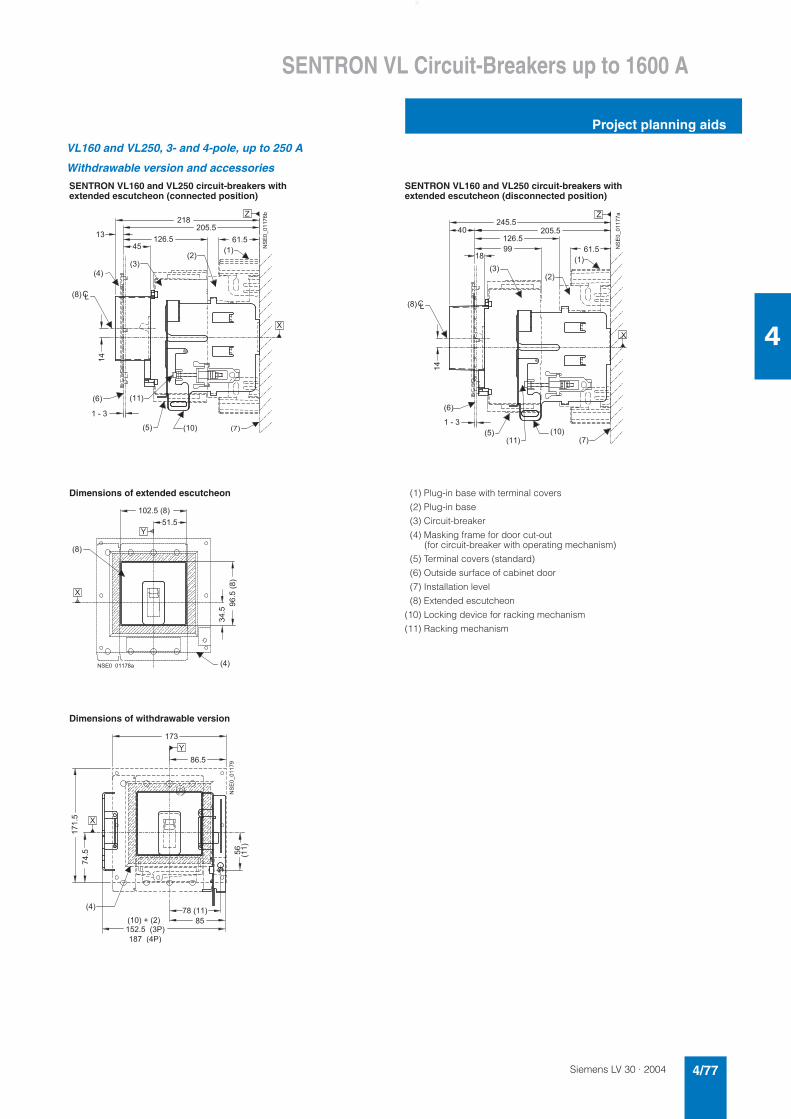
Siemens LV 30 · 2004 4/77
SENTRON VL Circuit-Breakers up to 1600 A
Project planning aids
4
VL160 and VL250, 3- and 4-pole, up to 250 A
Withdrawable version and accessories
SENTRON VL160 and VL250 circuit-breakers with extended escutcheon (connected position)
SENTRON VL160 and VL250 circuit-breakers with extended escutcheon (disconnected position)
Dimensions of extended escutcheon (1) Plug-in base with terminal covers
(2) Plug-in base
(3) Circuit-breaker
(4) Masking frame for door cut-out (for circuit-breaker with operating mechanism)
(5) Terminal covers (standard)
(6) Outside surface of cabinet door
(7) Installation level
(8) Extended escutcheon
(10) Locking device for racking mechanism
(11) Racking mechanism
Dimensions of withdrawable version
� � �
�
�
� � �
� � � � �
� � �
� � �
��
� �
� � �
� � �
� �
� �
� � � �
��
� �
� � � �
� � � � � �
� � � �
������ ��*
� � �
�
�
� � �
��
� � �
� �
� � �
� � �
� �
� �
� � �
��
� � � �
�
� �
� � � � �
� � �
� � � � � �
� � � � � �
� � � �
������ ���
� � �
�
� � �
�
� � � � � � � �
� � �
��������
���
� � � � � � � � �
�
�
� � �
� � � � + � � � �
� � � � � � � �
� � � � � � �
� ���
�����
� � �
� �
� � � � �
� � � � � �
���
� �
������ ��
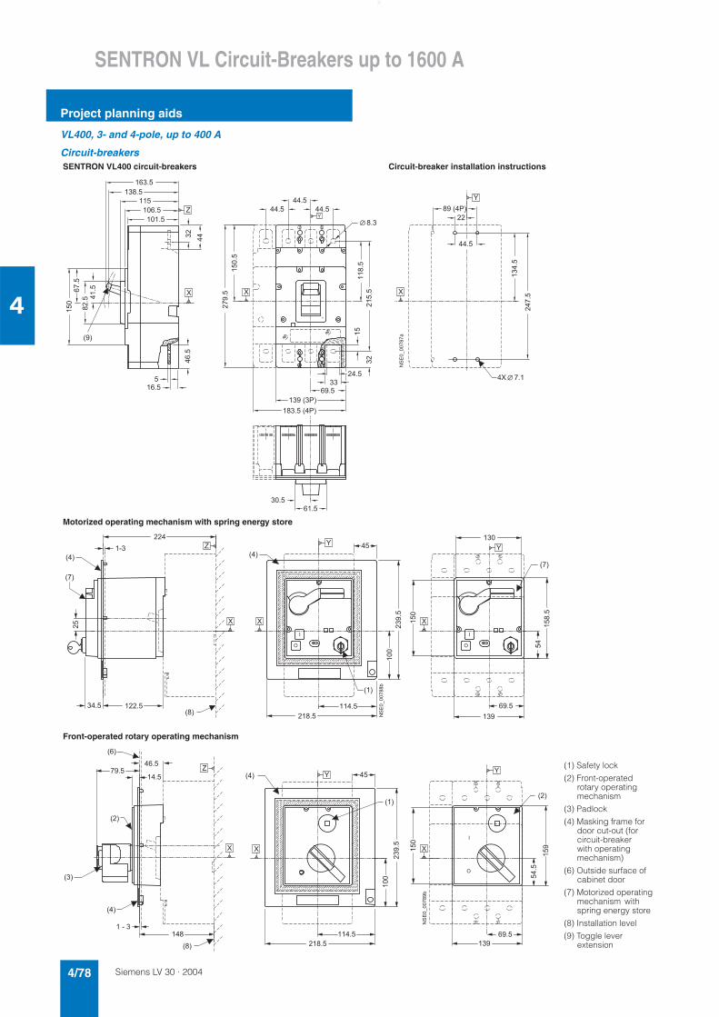
Siemens LV 30 · 20044/78
SENTRON VL Circuit-Breakers up to 1600 A
Project planning aids
4
VL400, 3- and 4-pole, up to 400 A
Circuit-breakersSENTRON VL400 circuit-breakers Circuit-breaker installation instructions
Motorized operating mechanism with spring energy store
Front-operated rotary operating mechanism
� � � �
� � � � � � �
� � �
� � �
� �
� � � � �
� � � �
� � � �
�����
� � � �
���
�����
� ��
����� ����
� �
� � � � � �
�
� � � � �� � � � �
�����
� � � � �
����
������
� � �
� ����
� � � � �
��
� � � � �
������
� �
�
�
� �
�
�
�����������
� �
� � �
� � �
�
���
�
� � � �
� � �
� � �
� � �
� � �
� � �
��
� � � � �
� � �
��
� � � � �
����
��
����
� � � �
� � � � �
� �
� �
� � �
��
��
��
� �
�
�
����������*
�
�
��
� �
� � �
� � �
� �
� � �
� � � �
� � �
� � �
� �
� � � �
� � �
��
����
� � � � �
� �
����
��
� � �
� � � � � �
� � � �
�
��
�
�
����������*
�
�
� � � �
� �
���
(1) Safety lock
(2) Front-operated rotary operating mechanism
(3) Padlock
(4) Masking frame for door cut-out (for circuit-breaker with operating mechanism)
(6) Outside surface of cabinet door
(7) Motorized operating mechanism with spring energy store
(8) Installation level
(9) Toggle lever extension
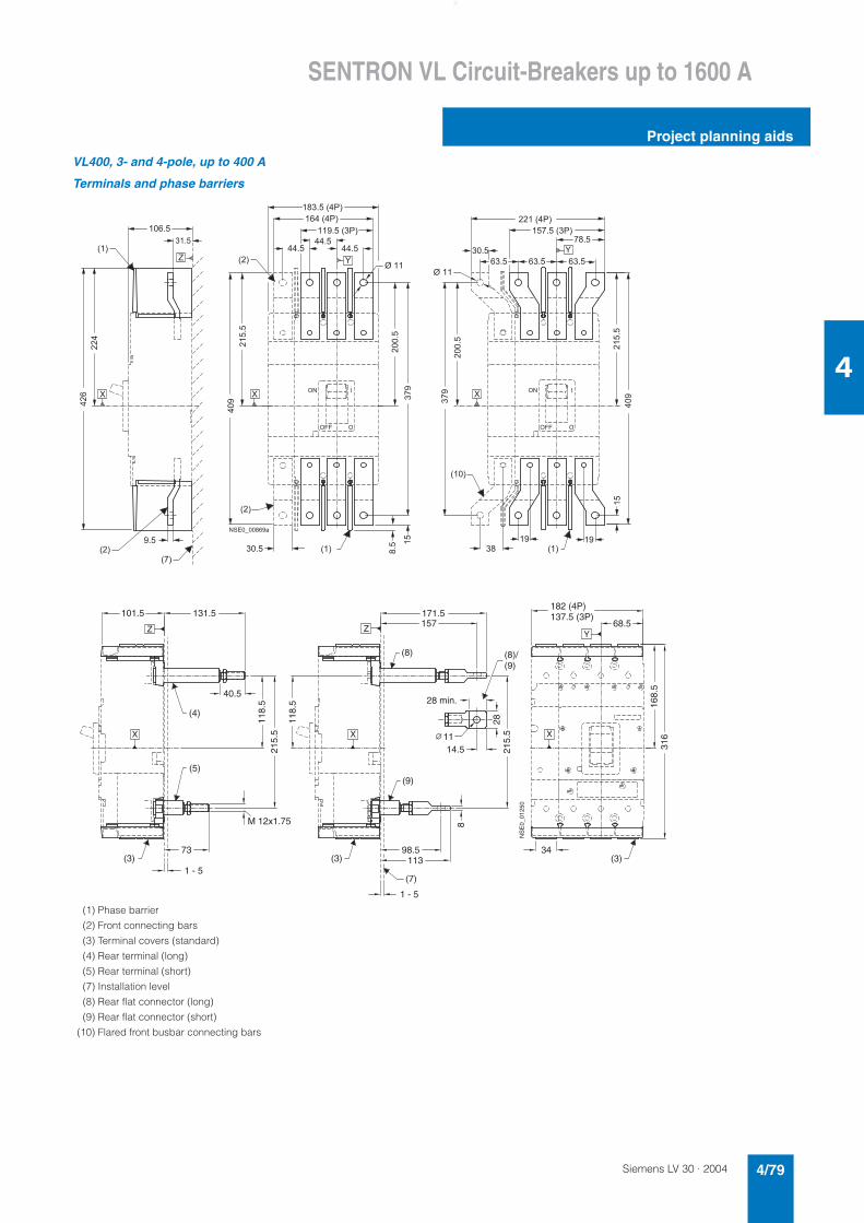
Siemens LV 30 · 2004 4/79
SENTRON VL Circuit-Breakers up to 1600 A
Project planning aids
4
VL400, 3- and 4-pole, up to 400 A
Terminals and phase barriers
���
� � �
���
� � �
� � �
����
�
�
� �
� � �
�
� �
� � �
� �
�
� �
� � � �
� �
���
� � � �
� � � � �
� ����
� � � �� � �
� � �
� � � � � �
� � � � � �
� � � � �
� � � � �
� � �
������
��
������
���
� ����
� � � � � � �
� � � � � �
�
�
� � �
� �
� � � �
� � �
�
�
�
�
�
�
� � � � � � � � � � �
� � � � �
, �
, �
���
� � �
� � � � � � �
(1) Phase barrier
(2) Front connecting bars
(3) Terminal covers (standard)
(4) Rear terminal (long)
(5) Rear terminal (short)
(7) Installation level
(8) Rear flat connector (long)
(9) Rear flat connector (short)
(10) Flared front busbar connecting bars
1 - 5(3)(3)
215.
5
73
40.5
118.
5
131.5
118.
5
101.5
1 - 5
316
168.
5
182 (4P) 137.5 (3P)
34(3)
28 min.
8
215.
528
68.5
98.5113
14.5
157171.5
(4)
(5)
(7)
(8)
(9)
Z ZY
X X X11
(8)/(9)
NS
E0_
0125
0
M 12x1.75
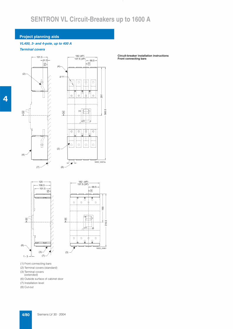
Siemens LV 30 · 20044/80
SENTRON VL Circuit-Breakers up to 1600 A
Project planning aids
4
VL400, 3- and 4-pole, up to 400 A
Terminal covers
(1) Front connecting bars
(2) Terminal covers (standard)
(3) Terminal covers (extended)
(6) Outside surface of cabinet door
(7) Installation level
(8) Cut-out
� � � �
� � �
� � �
� � �
� � �
� � � �
� � � � � �
� � � � � �
�� �
������
� � �
�� � �
�� �
�
� �
�
� � � � � � � � � � �
� �
� � �
Circuit-breaker installation instructionsFront connecting bars
� � �
� � �
� � � �
� � � �
� � � � � � �
� � � � � �
�
� � � � �
� � �
���
����
� �
� � �
� �
�
�
� �
� � �
� �
�
� � � � � � � � �
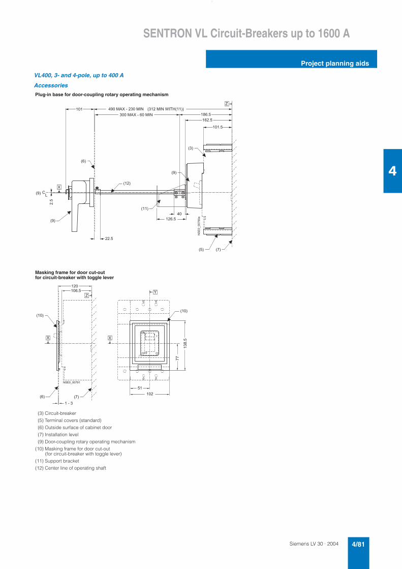
Siemens LV 30 · 2004 4/81
SENTRON VL Circuit-Breakers up to 1600 A
Project planning aids
4
VL400, 3- and 4-pole, up to 400 A
Accessories
Plug-in base for door-coupling rotary operating mechanism
Masking frame for door cut-out for circuit-breaker with toggle lever
(3) Circuit-breaker
(5) Terminal covers (standard)
(6) Outside surface of cabinet door
(7) Installation level
(9) Door-coupling rotary operating mechanism
(10) Masking frame for door cut-out (for circuit-breaker with toggle lever)
(11) Support bracket
(12) Center line of operating shaft
�
� � �
� �
� � �
� � � �
���
� � �
�
� � � �
� � � ' � � � � � � � � ' � �
� � � � � ' � � � � � � � � ' � �
� �
� � �
� � �
�
� � �
�
�����������
� � � �
� � �
� � � �
� �
� � �
� � � ' � � � ( � � # � � �
� � �
� � �
����
� � � � �
� � �
� � �
� �
� � �
� � � �
� � �
���
� � � �
� �
�
�
�
�
� � � � � � � � �
�
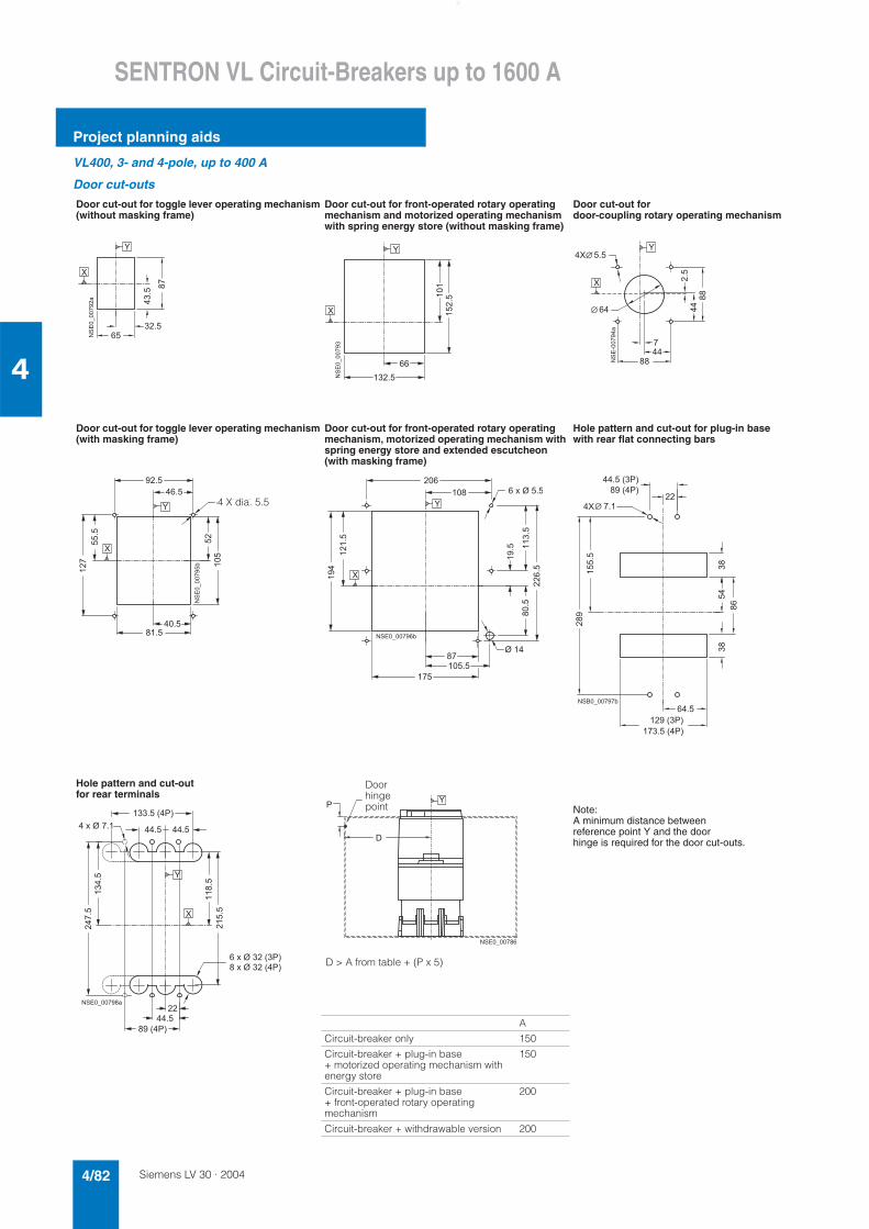
Siemens LV 30 · 20044/82
SENTRON VL Circuit-Breakers up to 1600 A
Project planning aids
4
VL400, 3- and 4-pole, up to 400 A
Door cut-outs
Door cut-out for toggle lever operating mechanism(without masking frame)
Door cut-out for front-operated rotary operating mechanism and motorized operating mechanism with spring energy store (without masking frame)
Door cut-out for door-coupling rotary operating mechanism
Door cut-out for toggle lever operating mechanism(with masking frame)
Door cut-out for front-operated rotary operating mechanism, motorized operating mechanism with spring energy store and extended escutcheon (with masking frame)
Hole pattern and cut-out for plug-in base with rear flat connecting bars
Hole pattern and cut-out for rear terminals
Note:A minimum distance between reference point Y and the door hinge is required for the door cut-outs.
A
Circuit-breaker only 150
Circuit-breaker + plug-in base + motorized operating mechanism with energy store
150
Circuit-breaker + plug-in base + front-operated rotary operating mechanism
200
Circuit-breaker + withdrawable version 200
��
� � �
� � � �
����
�
�
�����������
����
�
� � �
� � �
�
�
���������
���
�
��
��
� �
����������
���
��
� � - � , � � � �
� � � �
� � � � �
��
���
� � � � �
� � � �
����
��
�
�
����������*
4 X dia. 5.5
� ���
��
� � �
� � �
� � - � , � � � �
�����
�����
� �
� � �
��
���
� � � � �
, � �
�
�
� � � � � � � � � � *
��
� �
� � � � � � �
� � � � � �
� �
�����
������
��
� � � � �
� � � � � � �
� � � � �
����
� � " � � � � � � � *
� �
�
!
� � � � � � � � � �
Doorhingepoint
D > A from table + (P x 5)
����
� ����
� �
� � � � �
����
� � - � , � � �
�����
� � � � � �
�
�
� � � � � � � � � � �
� � - � , � � � � �
� � - � , � � � � � �
� � � � � � � �
� � � � � �
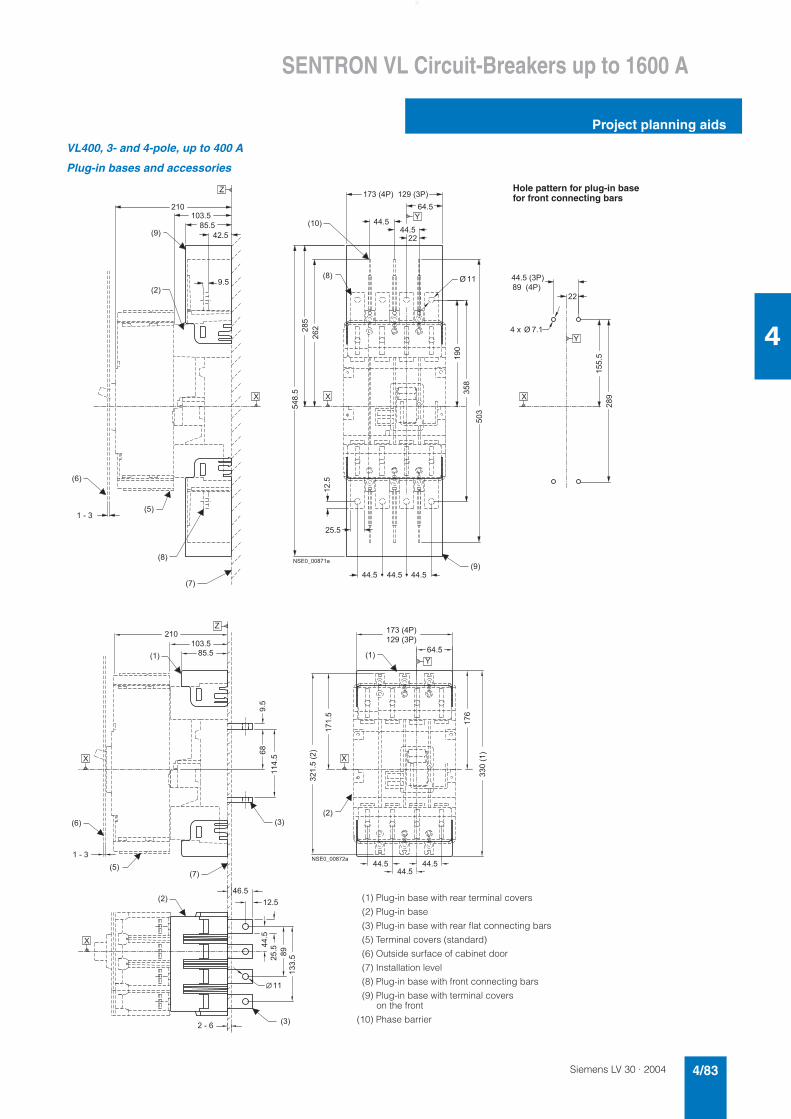
Siemens LV 30 · 2004 4/83
SENTRON VL Circuit-Breakers up to 1600 A
Project planning aids
4
VL400, 3- and 4-pole, up to 400 A
Plug-in bases and accessories
���
� � �
� � �
� � �
� � �
� � � �
����
���
���
�����
� � �
� � � � � � � �
� � � �
� � � �
� � � �
� � � � �
� � � � �
� � �
� � �
� � �
� �
����
� � � � �
� � � � �
� �
� � � �
� � �
� � �
� � � � � � � � � � � �
���
����
����
� � � � � � �
� � � � � � �
� �
�
�
�
�
� � � � � � � � � �
� � - � � � � � � �
� � � �
Hole pattern for plug-in base for front connecting bars
� � � � �
� � � � �
� �
� � �
� � �
� � � �
� � �
� � �
� � � � �
� � � �
���
� �
� � � � �
� ���
��� �
� � � � �
� � � � � � � � � �
� � �
� ������
����
����
� �
�����
� � � �
���
��
���
� �
�����
� � � �
�
�
�
�
�
� � � � � � � � � � �
� � �
� �
(1) Plug-in base with rear terminal covers
(2) Plug-in base
(3) Plug-in base with rear flat connecting bars
(5) Terminal covers (standard)
(6) Outside surface of cabinet door
(7) Installation level
(8) Plug-in base with front connecting bars
(9) Plug-in base with terminal covers on the front
(10) Phase barrier
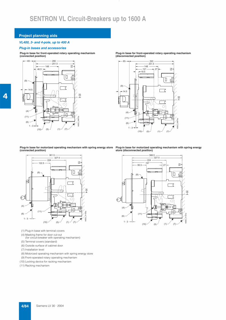
Siemens LV 30 · 20044/84
SENTRON VL Circuit-Breakers up to 1600 A
Project planning aids
4
VL400, 3- and 4-pole, up to 400 A
Plug-in bases and accessories
Plug-in base for front-operated rotary operating mechanism (connected position)
Plug-in base for front-operated rotary operating mechanism (disconnected position)
Plug-in base for motorized operating mechanism with spring energy store (connected position)
Plug-in base for motorized operating mechanism with spring energy store (disconnected position)
(1) Plug-in base with terminal covers
(4) Masking frame for door cut-out (for circuit-breaker with operating mechanism)
(5) Terminal covers (standard)
(6) Outside surface of cabinet door
(7) Installation level
(8) Motorized operating mechanism with spring energy store
(9) Front-operated rotary operating mechanism
(10) Locking device for racking mechanism
(11) Racking mechanism
� �
� � �
� � �
� �
� � �
� � �
� � �� �� � �� � �
�
� � � �
� � �
� � � � �
�
����������
� � � �
� � �
� � �� �� � �� � �
� � �
� �
� � �
� � �
� � �
� � �
� � �
� � � � �
� �
� �
� � �
�
�
�����������
� � �
� � �
� � �
� � �
� � � �
� � � �
� � � �
� � � � �
� � �
� � �� �� � � � � �
� �
� � � �
�
�
������ ���
� � �
� � � �
� � � �
� � �
� � � � �
� � �
� � �� �
� �
� � � � � �
� � �
� � �
� � � �
� � � � �
�
�
������ � �
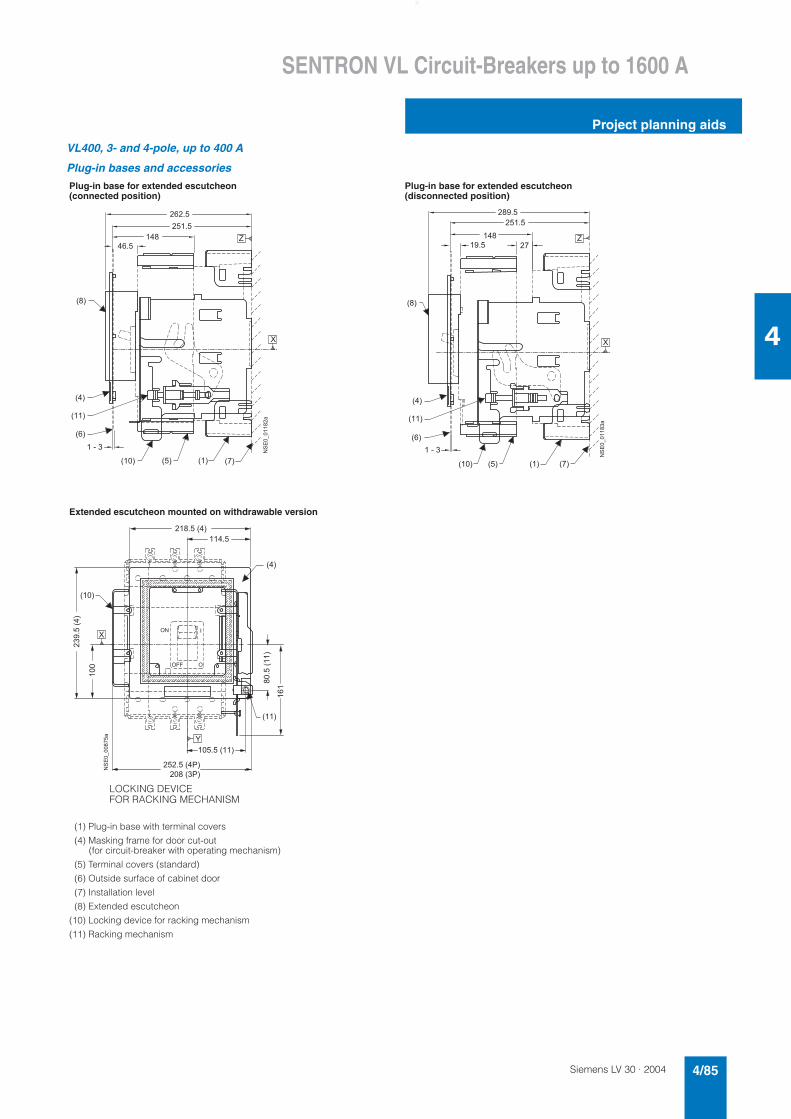
Siemens LV 30 · 2004 4/85
SENTRON VL Circuit-Breakers up to 1600 A
Project planning aids
4
VL400, 3- and 4-pole, up to 400 A
Plug-in bases and accessories
Plug-in base for extended escutcheon(connected position)
Plug-in base for extended escutcheon(disconnected position)
Extended escutcheon mounted on withdrawable version
(1) Plug-in base with terminal covers
(4) Masking frame for door cut-out (for circuit-breaker with operating mechanism)
(5) Terminal covers (standard)
(6) Outside surface of cabinet door
(7) Installation level
(8) Extended escutcheon
(10) Locking device for racking mechanism
(11) Racking mechanism
� � �� � � � �� � �
� �
� � �
� � �
� � �
� � � � � �
� � � � �
� � �
� � �
�
�
������ ���
� � � �
� � �� �� � �� � �
� � �
� �
� � �
� � �
� � � � �
� � �
� � � � � �
� � �
� � �
� � �
�
�
������ ��
� � �
� � � � � � � �
� � �
������ �
� � �
��
��������
� � � � � � �
� �
�
�
� � �
� �
�
�
�����������
� � � � � � � � �
� � � � � � � � �
�
LOCKING DEVICE FOR RACKING MECHANISM
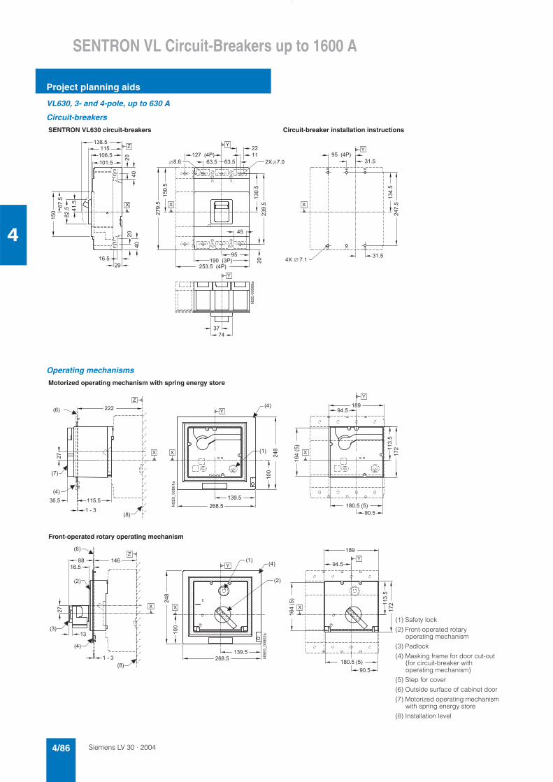
Siemens LV 30 · 20044/86
SENTRON VL Circuit-Breakers up to 1600 A
Project planning aids
4
VL630, 3- and 4-pole, up to 630 A
Circuit-breakers
Operating mechanisms
SENTRON VL630 circuit-breakers Circuit-breaker installation instructions
� ���
�
�
��
�����
�����
��� ����
�������
������
��
��
��
��
�����
��������
������
���� ����
�����
����������������
����
����
�����
����
�����
�����
�������������
���������
��� ����� ��
����
��
Motorized operating mechanism with spring energy store
Front-operated rotary operating mechanism
� � �
� � �
� � �
� � �
�
�
�
�
� ��
� � �
�
� � �
� � �
� � �
��
� � �� � � �
� � � � � � � �
� � �
� � � � �
������
��
���
��
��
� �
��������� �
� � � �
� �
� � �
� � �
� � �
�
� � �
��
�
� �
� � �
� � �
�
��
� � �
� �
� � �
� �
� � � �
� � � � � � � �
��
���
� � �
� � � � �
������
��
� � �
���
�����������
�
� � � �
(1) Safety lock
(2) Front-operated rotary operating mechanism
(3) Padlock
(4) Masking frame for door cut-out (for circuit-breaker with operating mechanism)
(5) Step for cover
(6) Outside surface of cabinet door
(7) Motorized operating mechanism with spring energy store
(8) Installation level
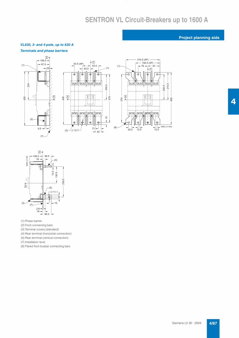
Siemens LV 30 · 2004 4/87
SENTRON VL Circuit-Breakers up to 1600 A
Project planning aids
4
VL630, 3- and 4-pole, up to 630 A
Terminals and phase barriers
(1) Phase barrier
(2) Front connecting bars
(3) Terminal covers (standard)
(4) Rear terminal (horizontal connection)
(5) Rear terminal (vertical connection)
(7) Installation level
(8) Flared front busbar connecting bars
�
� �
� � �
� � �
�
� � �
�
� �
� � �
� �
�
� �
� � � � � � � � �
� � � �
���
� � �
���
� �
� � � �
���
� � � � � � �
� � �
�
� � �
� � �
� �
�
�����
��
� � � �
� � � � � � �
� �
� ���
���
�����
�
�
� � �
� � � � � � � � �
� � �
��
� �
� � �
��
� � �
� � �
� � �
� � � �
�
�
� � � �
�
� � � �
���
���
�
�
����
������ ��
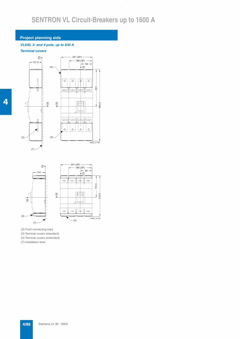
Siemens LV 30 · 20044/88
SENTRON VL Circuit-Breakers up to 1600 A
Project planning aids
4
VL630, 3- and 4-pole, up to 630 A
Terminal covers
(2) Front connecting bars
(3) Terminal covers (standard)
(4) Terminal covers (extended)
(7) Installation level
� � �
� � �
� � �
�
� � �
�
�
�
� � �
��
�����
� � � � �
� � � � � �
� �
� � � � � � � �
�
� �
� � �
�
�
�
� �
� �
� � � � �
� � � � � �
� �
����
���
� � � � � � � �
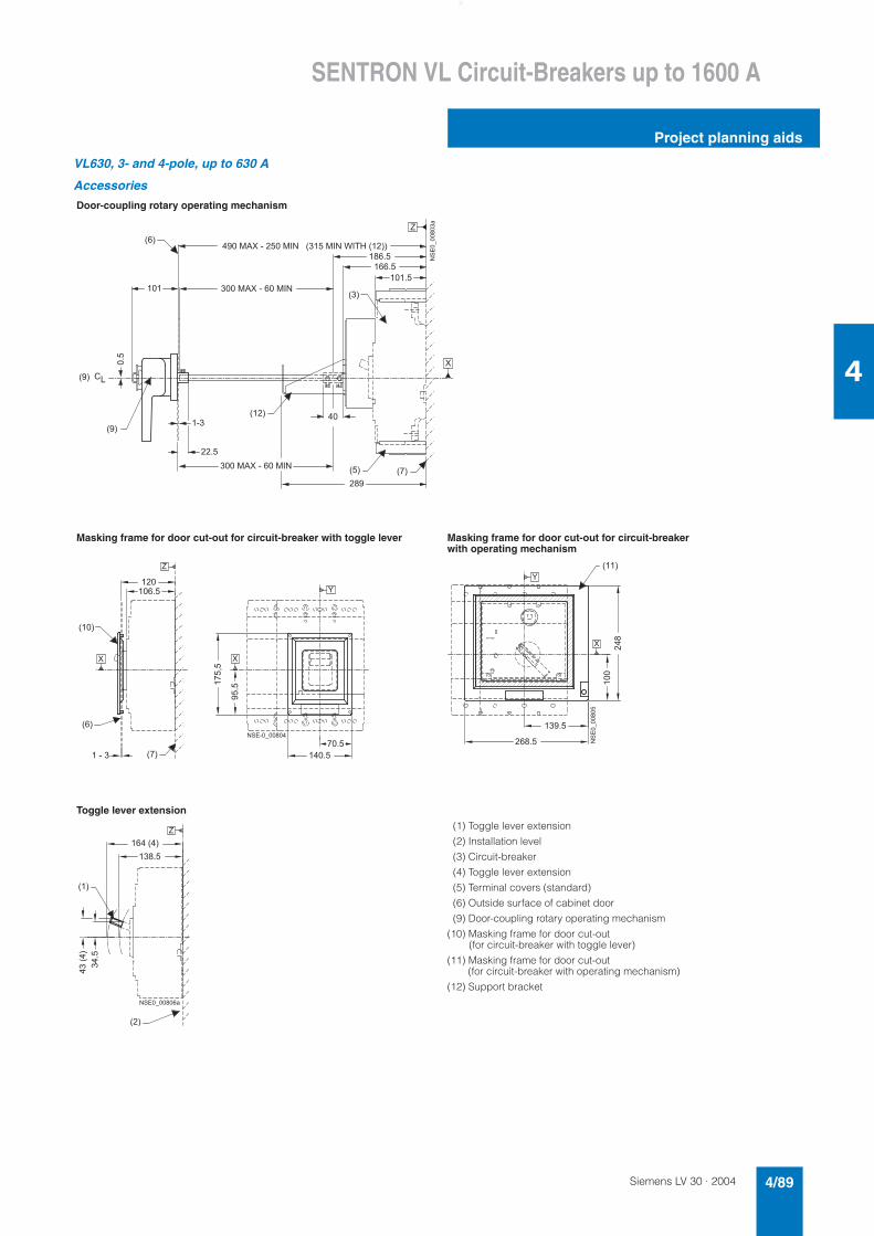
Siemens LV 30 · 2004 4/89
SENTRON VL Circuit-Breakers up to 1600 A
Project planning aids
4
VL630, 3- and 4-pole, up to 630 A
Accessories
Door-coupling rotary operating mechanism
Masking frame for door cut-out for circuit-breaker with toggle lever Masking frame for door cut-out for circuit-breaker with operating mechanism
Toggle lever extension
(1) Toggle lever extension
(2) Installation level
(3) Circuit-breaker
(4) Toggle lever extension
(5) Terminal covers (standard)
(6) Outside surface of cabinet door
(9) Door-coupling rotary operating mechanism
(10) Masking frame for door cut-out (for circuit-breaker with toggle lever)
(11) Masking frame for door cut-out (for circuit-breaker with operating mechanism)
(12) Support bracket
� � �
� � �
��
� � �
� � � ' � � � � � � � � ' � �
�
���
� � � �
�
� � � � ' � � � � � � � � � ' � �
����������
� � �
� � � �
� � � �
� �
� � �
�
�
� �
� � � � � �
� � � ' � � � ( � � # � � � � �
� � � ' � � � � � � � � ' � �
� � �
� � �
� � �
� � �
�
�
�
�
� � � �
� � �
� �
� � � �
��.�
����
� � � �
� � � � � � � � � � �
�
� �
�
� � � � �
� � �
��
���
� � � !
����������
� � �
� �
�
� � � �
� � � � � �
�����
���
� � � � � � � � � � �
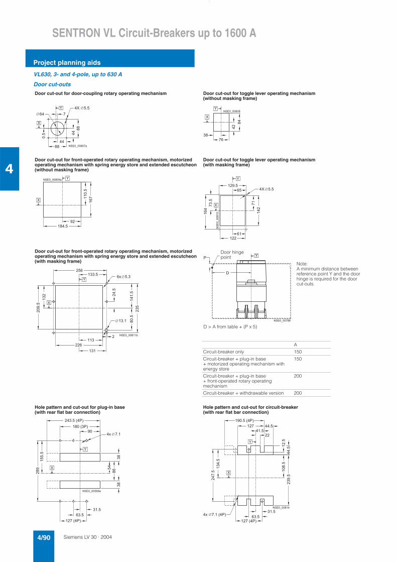
Siemens LV 30 · 20044/90
SENTRON VL Circuit-Breakers up to 1600 A
Project planning aids
4
VL630, 3- and 4-pole, up to 630 A
Door cut-outs
Door cut-out for door-coupling rotary operating mechanism Door cut-out for toggle lever operating mechanism(without masking frame)
Door cut-out for front-operated rotary operating mechanism, motorized operating mechanism with spring energy store and extended escutcheon (without masking frame)
Door cut-out for toggle lever operating mechanism(with masking frame)
Door cut-out for front-operated rotary operating mechanism, motorized operating mechanism with spring energy store and extended escutcheon (with masking frame)
A
Circuit-breaker only 150
Circuit-breaker + plug-in base + motorized operating mechanism with energy store
150
Circuit-breaker + plug-in base + front-operated rotary operating mechanism
200
Circuit-breaker + withdrawable version 200
Hole pattern and cut-out for plug-in base (with rear flat bar connection)
Hole pattern and cut-out for circuit-breaker(with rear flat bar connection)
�
�
���
� �
��
� �
� �
� �
��
� � �� � �
� � � � � � � � � � �
�
� �
��
��
� � � � � � � � � �
�
�
�
�
� � � �
� �
���
��
� � � � � � � � � � �
� �
�
� � � �
���
��
� �
�
��
� � �
�������� �
�
� �
�
D > A from table + (P x 5)
Note:A minimum distance between reference point Y and the door hinge is required for the door cut-outs.
�
!
� � � � � � � � � �
Door hinge point
�
�
� � �
� � � �
�����
�
� �
��
�
� ��
� �
�
� � � � � � � � *
� -
����
����
�
�
� � � � � � � �
� � �
� � � � � �
� � � � �
����
���
��
� �
��
�
� �
�
� � � � � � � � � � �
� � � -
�
����
�����
���
� � � � � �
� � �
� � �
� � � � � � � �
� �
� �
� �
���
����
����
� � � �
� � � � � �� -
�
� � � � � � � � �
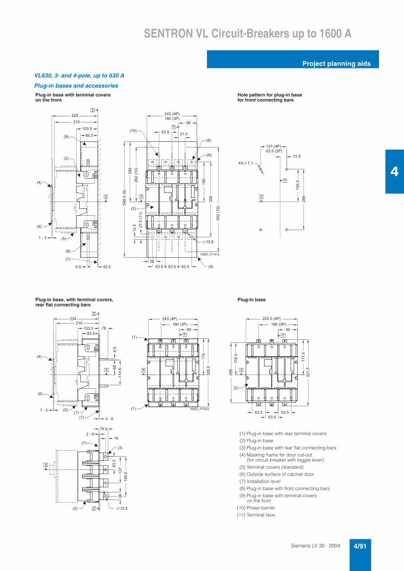
Siemens LV 30 · 2004 4/91
SENTRON VL Circuit-Breakers up to 1600 A
Project planning aids
4
VL630, 3- and 4-pole, up to 630 A
Plug-in bases and accessories
Plug-in base with terminal covers on the front
Hole pattern for plug-in base for front connecting bars
Plug-in base, with terminal covers, rear flat connecting bars
Plug-in base
� � �
� � �
� � �
� � �
� � �
� � �
� � �
�
� � �
� � �
� � �
� � �
� � �
� � � �
� � �
� � � �
� � �
� � � �
� � � �
���������
� � �
���
� �
� � �
����� ��
���
� � � � � �
� � � � �
� � �
� � �
� �
����� ��
���
� � �
���
�����
� � � � � �
� �
����
� �
�
� �
�
�
� � � � � � � �
������ �
� � � � � � � � �
� � � � � �
� � �
� � �
� � �
� � �
� � �
� � �
� �
� �
� �
� � �
� � � � � � � �
� � � �
� � � � �
� � �
� � �
� � � �
��
�
� � � �
����
���
�����
����
� �
��
� � � � �
� � �
����
� �
� � � � � �
� � � � �
� � �
����
����
��
� � � �
�����
� � � �
� � � �
� � � � �
� � �
� ���
� ���
�
�
�
� �
�
�
�
� � � � � � � � �
� �
(1) Plug-in base with rear terminal covers
(2) Plug-in base
(3) Plug-in base with rear flat connecting bars
(4) Masking frame for door cut-out (for circuit-breaker with toggle lever)
(5) Terminal covers (standard)
(6) Outside surface of cabinet door
(7) Installation level
(8) Plug-in base with front connecting bars
(9) Plug-in base with terminal covers on the front
(10) Phase barrier
(11) Terminal face
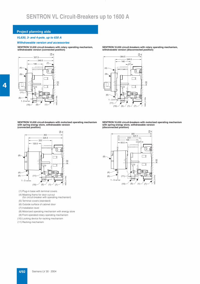
Siemens LV 30 · 20044/92
SENTRON VL Circuit-Breakers up to 1600 A
Project planning aids
4
VL630, 3- and 4-pole, up to 630 A
Withdrawable version and accessories
SENTRON VL630 circuit-breakers with rotary operating mechanism,withdrawable version (connected position)
SENTRON VL630 circuit-breakers with rotary operating mechanism,withdrawable version (disconnected position)
SENTRON VL630 circuit-breakers with motorized operating mechanism with spring energy store, withdrawable version (connected position)
SENTRON VL630 circuit-breakers with motorized operating mechanism with spring energy store, withdrawable version (disconnected position)
(1) Plug-in base with terminal covers
(4) Masking frame for door cut-out (for circuit-breaker with operating mechanism)
(5) Terminal covers (standard)
(6) Outside surface of cabinet door
(7) Installation level
(8) Motorized operating mechanism with energy store
(9) Front-operated rotary operating mechanism
(10) Locking device for racking mechanism
(11) Racking mechanism
� � �
� � �
� �
� � �
� � �
� � �
� �� � �
�
� �
� � � �
� �
� � � � � �
�
������ ���
� � �
� � �
� � �
� � �
� �
� � � � � � � �
� � �
� �
� �
� � � �
� � � � � �
�
�
������ ���
� � �
� � �
� � � � �
� � � � � �� � � � �
� � �
� � �
� � � �
� � � � �
� � � �
�
�
������ ���
� � �
� � �
� � �
� �
� � �
� � �
� � � �
� � �
� � �� �
� � � � �
�
�
������ � �
� � � � � �� � � � �
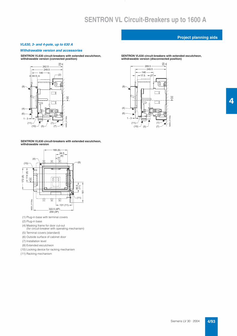
Siemens LV 30 · 2004 4/93
SENTRON VL Circuit-Breakers up to 1600 A
Project planning aids
4
VL630, 3- and 4-pole, up to 630 A
Withdrawable version and accessories
SENTRON VL630 circuit-breakers with extended escutcheon,withdrawable version (connected position)
SENTRON VL630 circuit-breakers with extended escutcheon,withdrawable version (disconnected position)
SENTRON VL630 circuit-breakers with extended escutcheon,withdrawable version
(1) Plug-in base with terminal covers
(2) Plug-in base
(4) Masking frame for door cut-out (for circuit-breaker with operating mechanism)
(5) Terminal covers (standard)
(6) Outside surface of cabinet door
(7) Installation level
(8) Extended escutcheon
(10) Locking device for racking mechanism
(11) Racking mechanism
�
�
������ ���
� �
� � �
� � �
� � �
� � �
� �
� � � � � �
� � �
� � � � � �
� �
� � �
� � � �
� � � � � �
������ ��
�
�
� � �
� � �
� � �
� � �
� �
� � � � � �
� �
� � �
� � � � � �
� � �
� �
� � � � � �
� �
�
�
������ ���
�
� �
� � �
� � �
� � �
� � � � � � � �
� � � � � �
������
�����
� � �
� � � � � �
� � � � �
� � �
������
� �
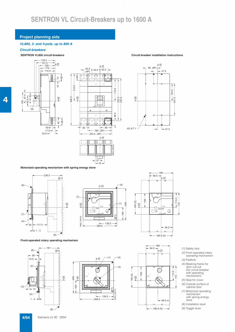
Siemens LV 30 · 20044/94
SENTRON VL Circuit-Breakers up to 1600 A
Project planning aids
4
VL800, 3- and 4-pole, up to 800 A
Circuit-breakers
SENTRON VL800 circuit-breakers Circuit-breaker installation instructions
Motorized operating mechanism with spring energy store
Front-operated rotary operating mechanism
� � �
�
�
� � � �
� �
� � � �
� � �
����������
��� � ���
�
� � �
� � � � � � �
� � �
� � � � � �
� � � � � � � � �
� �
���
�
���
���
������
� ����
� � �
� � �
� � � �
�����
���
� � �
� � � �
�����
� � �
����
� � �
������
�
� �
� � �
�
�
�������� ��
� � �
� � �
� �
� � � � �
��
���
� � �
� � �
� � �
� � �
� � �
� �
� � �
� � � � � �
� � � �
� � � � �
� � �
� � � � � � � �
� � � � � �
� � � �
��
���
������
� � � � ���
���
� � / � � �� �
�
� �
�
�
�
�������� ��
��
� � � �
� � �
� �
� � �
� � �
� � �
� �
� � �
� � �
�
� � � �
� � � �
� �
�
� � �
� � � � � � � �
� � � � � �
��
���
� � � �
������
� � � � �
���
���
�
��
�
�
�
�������� ��
��
� � � �
(1) Safety lock
(2) Front-operated rotary operating mechanism
(3) Padlock
(4) Masking frame for door cut-out (for circuit-breaker with operating mechanism)
(5) Step for cover
(6) Outside surface of cabinet door
(7) Motorized operating mechanism with spring energy store
(8) Installation level
(9) Toggle lever
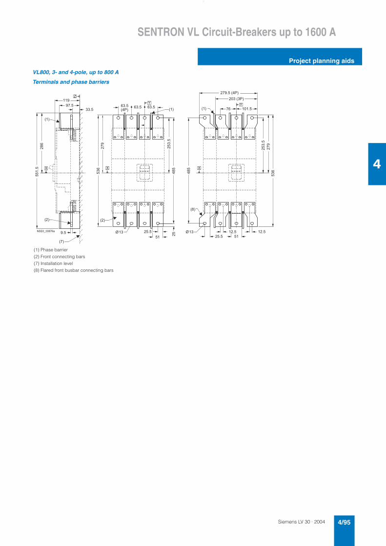
Siemens LV 30 · 2004 4/95
SENTRON VL Circuit-Breakers up to 1600 A
Project planning aids
4
VL800, 3- and 4-pole, up to 800 A
Terminals and phase barriers
(1) Phase barrier
(2) Front connecting bars
(7) Installation level
(8) Flared front busbar connecting bars
� � �
� � �
� �
�
� � �
� � �
� �� �
� � �
�� ��
� � �
���
� � � � �
� �
�
� � � �
��
� � � �
� � � �
�
���
���
� � � � � � �
����
���
���
� �
� � � � � � � � �
� � � � �
� � �
��
� � � �
����
���
�
�
� � �
� � �
�
� �
� � � � � � � � � � �
, ,
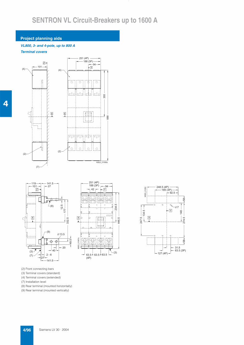
Siemens LV 30 · 20044/96
SENTRON VL Circuit-Breakers up to 1600 A
Project planning aids
4
VL800, 3- and 4-pole, up to 800 A
Terminal covers
(2) Front connecting bars
(3) Terminal covers (standard)
(4) Terminal covers (extended)
(7) Installation level
(8) Rear terminal (mounted horizontally)
(9) Rear terminal (mounted vertically)
� � �
� � �
� � �
�
� � �
� � �
�
���
� � � � � �
� � � � �
� �
��
� �
�
� � � � � � � � � �
����
���
���
� �
� �
� � � � �
� �
� � �
� � �
��
� � �
� �
�
�
�����
����
� � � � � �� � �
� � �
� �
� �
� � � � � �
� � � � �
������ ����
��
� �
� �
� � �
� �
� � �
� �
� � � � � � � � �
� � � � � �
� �
� � � � � �
� � � � �
�����
���
� � � �
��
�����
��
��
������ ���
�
�
�
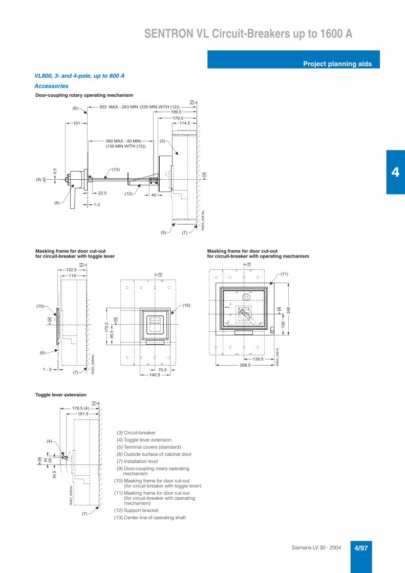
Siemens LV 30 · 2004 4/97
SENTRON VL Circuit-Breakers up to 1600 A
Project planning aids
4
VL800, 3- and 4-pole, up to 800 A
Accessories
Door-coupling rotary operating mechanism
Masking frame for door cut-out for circuit-breaker with toggle lever
Masking frame for door cut-out for circuit-breaker with operating mechanism
Toggle lever extension
� � �
� � � ��
� � �
� � � � � �
� �
�
� � � � ' � � � � � � � � ' � �
����
� �
�
� � � � �
� � � ' � � � � � � � � ' � �
� �
� � � �
� � � � �
� � � � �
�
�������� ��
� � �
� �
� � � ' � � � ( � � # � � � � �
� � � ' � � � ( � � # � � � � �
� � �
� � �
� � �� � �
� � � �
� �
� � � �
� � � � �
� � � � �
����
����
��
�
�
�����������
� �
� � � � � �
� � � �
��
���
�
�
�������� �
� � �
� � �
�
����
� � � �
� � � � � � � �
�����������
�
�
���
(3) Circuit-breaker
(4) Toggle lever extension
(5) Terminal covers (standard)
(6) Outside surface of cabinet door
(7) Installation level
(9) Door-coupling rotary operating mechanism
(10) Masking frame for door cut-out (for circuit-breaker with toggle lever)
(11) Masking frame for door cut-out (for circuit-breaker with operating mechanism)
(12) Support bracket
(13) Center line of operating shaft
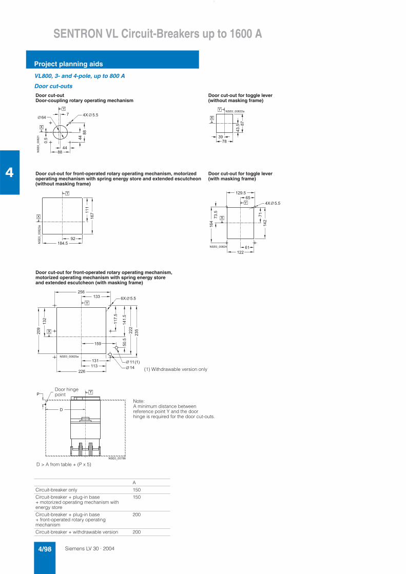
Siemens LV 30 · 20044/98
SENTRON VL Circuit-Breakers up to 1600 A
Project planning aids
4
VL800, 3- and 4-pole, up to 800 A
Door cut-outs
Door cut-out Door-coupling rotary operating mechanism
Door cut-out for toggle lever (without masking frame)
Door cut-out for front-operated rotary operating mechanism, motorized operating mechanism with spring energy store and extended escutcheon (without masking frame)
Door cut-out for toggle lever (with masking frame)
Door cut-out for front-operated rotary operating mechanism, motorized operating mechanism with spring energy store and extended escutcheon (with masking frame)
A
Circuit-breaker only 150
Circuit-breaker + plug-in base + motorized operating mechanism with energy store
150
Circuit-breaker + plug-in base + front-operated rotary operating mechanism
200
Circuit-breaker + withdrawable version 200
�
���
� �
���
� �
� � �
� � �
���
� � �� �
�
���������
�
� �
��� ��
�
�
� � � � � � � � � � �
� �
� � � �
��
�
�
����������
�
����
���
� �
�
� � � � �
� � �
���
�
�
� � � � �
� � � � � � � � � �
�
� � � �
��
���
� � � �
�
�
���
���
� ���
����
�
� � � � �
�
�
� � � � � � � � � � �
����
� �
� �
(1) Withdrawable version only
�
!
� � � � � � � � � �
Note:A minimum distance between reference point Y and the door hinge is required for the door cut-outs.
Door hingepoint
D > A from table + (P x 5)
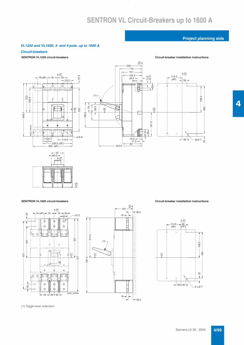
Siemens LV 30 · 2004 4/99
SENTRON VL Circuit-Breakers up to 1600 A
Project planning aids
4
VL1250 and VL1600, 3- and 4-pole, up to 1600 A
Circuit-breakers
SENTRON VL1250 circuit-breakers Circuit-breaker installation instructions
SENTRON VL1600 circuit-breakers Circuit-breaker installation instructions
(1) Toggle lever extension
� �
�
� � � �
� � � � �
� � �
� � � � � � � � �
� � �
������
� -
���
�����
���
� � � � � � �
� � � �
�
����
�����
� � � �
��
�����
�����
��
���
� � � � � � � � � � � �
� � � �
���
���
��
���
� � � � �
� � �
�
� � �
� � � �
� � �
��
�
� �
�
� � �
�
�
�
� � �
�
� �
�
�
�
�����������
����
�
� � �
� � �
� �
��
� ��
� �
��
���
����
����
���
�� ��
����
� � � � � � � � � � � �
�
� � � �
� �
��
�
� � �
� �
��
�
� � �
- -
�
� � � � � � � � � � �
�� �
� �
� �
�
� � �
�
��
�����
���
� � � �
� � �
� �
�
� � - � , � �
-
� �
�
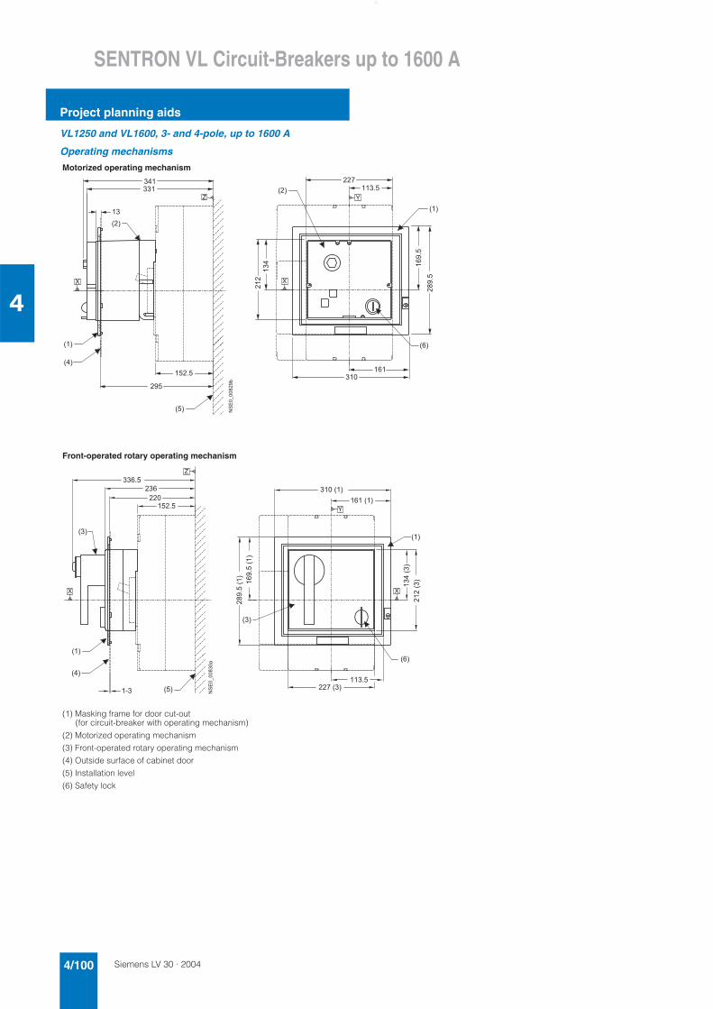
Siemens LV 30 · 20044/100
SENTRON VL Circuit-Breakers up to 1600 A
Project planning aids
4
VL1250 and VL1600, 3- and 4-pole, up to 1600 A
Operating mechanisms
Motorized operating mechanism
Front-operated rotary operating mechanism
(1) Masking frame for door cut-out (for circuit-breaker with operating mechanism)
(2) Motorized operating mechanism
(3) Front-operated rotary operating mechanism
(4) Outside surface of cabinet door
(5) Installation level
(6) Safety lock
� � �
� � �
� �
� � �
� �
� � �
� � �
�
�
�����
����
� � �
� � � � �
�
�
��
����������*
�
� �
� � �
�
� �
� �
� � �
� �
� � �
� �
� � �
� �
������ �
������� �
� �
� � � �
� � � �
����
� ����
� �
� �
� � �
� � � � �
� � �
�
��
�
����������
� � � � � �
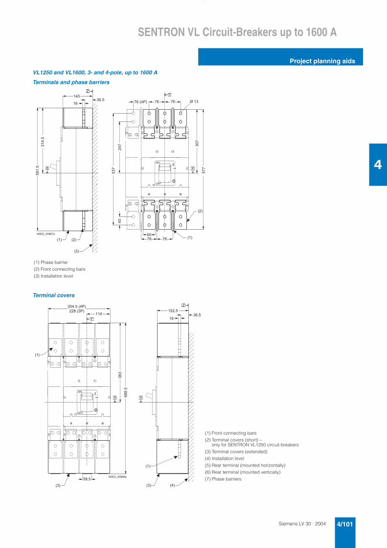
Siemens LV 30 · 2004 4/101
SENTRON VL Circuit-Breakers up to 1600 A
Project planning aids
4
VL1250 and VL1600, 3- and 4-pole, up to 1600 A
Terminals and phase barriers
Terminal covers
(1) Phase barrier
(2) Front connecting bars
(3) Installation level
� �
� � �
� �
� �
� � �
�
���
��
����
� � � � � � �
� �
���
���
�� ���
����
� � �
� � �
�
��
�
� � �
� �
��
� � �
�
� �
�
�
� � � � � � � � � � �
, � �
� �
� �
� �
� �
� �
�
� � �
� � � � � � � �
� � � � � �
�
�����
�
� � � �
�
� � � �
��
�
� � �
� �
��
�
�
�
� � � � � � � � � � �
� � � �
(1) Front connecting bars
(2) Terminal covers (short) – only for SENTRON VL1250 circuit-breakers
(3) Terminal covers (extended)
(4) Installation level
(5) Rear terminal (mounted horizontally)
(6) Rear terminal (mounted vertically)
(7) Phase barriers
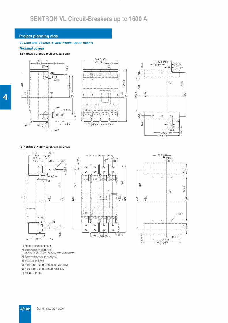
Siemens LV 30 · 20044/102
SENTRON VL Circuit-Breakers up to 1600 A
Project planning aids
4
VL1250 and VL1600, 3- and 4-pole, up to 1600 A
Terminal covers
SENTRON VL1250 circuit-breakers only
SENTRON VL1600 circuit-breakers only
���
�����
� �
�
���
���
� �
� ��
����
����
� � � �
� �
� � �
� �� � � � � � � �
� � � � �
� � � � � � � �
� � � � � �
������ ��
� � �
��
��
� �
� �
� � �
� � �
� � �� � �
��
����
� � � � �
�
� � � � �
� � � � � � � �
����
��
��
����
�
�����
� � � �
�
� � � � � � � �
� � � � � � �
� �
� �
������ ���
�
�
�
� �
���
���
��
���
��
���
� � �
���
� � � �
�
� �
�
�
� � �
��
)
����
�
� �
� �
� �� �
��
� �
������ ���
�
�
� �
� � �
� � �
� � � � � �
(1) Front connecting bars
(2) Terminal covers (short) – only for SENTRON VL1250 circuit-breaker
(3) Terminal covers (extended)
(4) Installation level
(5) Rear terminal (mounted horizontally)
(6) Rear terminal (mounted vertically)
(7) Phase barriers
���
� � � � � � � �
� � � � �
�
��
��
� �
� � � � � � �
� � � � � �
��
��
��
�������
������ ���
�
�
�
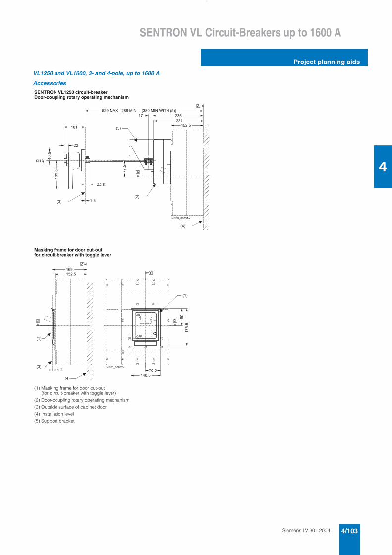
Siemens LV 30 · 2004 4/103
SENTRON VL Circuit-Breakers up to 1600 A
Project planning aids
4
VL1250 and VL1600, 3- and 4-pole, up to 1600 A
Accessories
SENTRON VL1250 circuit-breakerDoor-coupling rotary operating mechanism
Masking frame for door cut-out for circuit-breaker with toggle lever
(1) Masking frame for door cut-out (for circuit-breaker with toggle lever)
(2) Door-coupling rotary operating mechanism
(3) Outside surface of cabinet door
(4) Installation level
(5) Support bracket
� � �
� �
��
� � �
� � �
����
����
� � �
� �
� � � � �
����
� � � � ' � � � � � � � � � ' � �
�
� � � � �
� �
� �
�
�
� � � � � � � � �
�
� � � � ' � � � ( � � # � � � � �
� � �
� �
� �
� �
� � �
� � � �
� � � � �
��
����
� � � � �
� � �
�
��
�
� � �
� �
��
�
�
�
�
� � � � � � � � � �
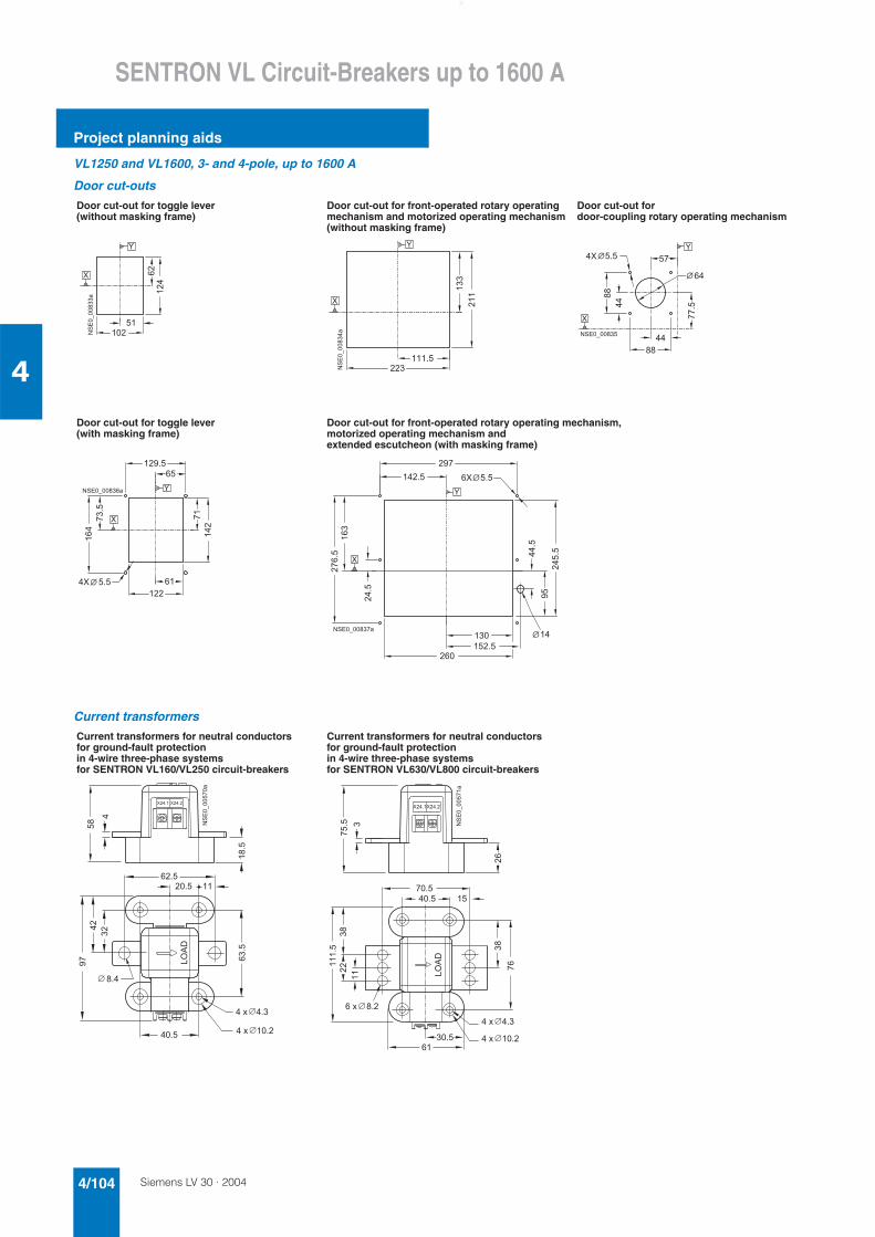
Siemens LV 30 · 20044/104
SENTRON VL Circuit-Breakers up to 1600 A
Project planning aids
4
VL1250 and VL1600, 3- and 4-pole, up to 1600 A
Door cut-outs
Current transformers
Door cut-out for toggle lever (without masking frame)
Door cut-out for front-operated rotary operating mechanism and motorized operating mechanism (without masking frame)
Door cut-out for door-coupling rotary operating mechanism
Door cut-out for toggle lever (with masking frame)
Door cut-out for front-operated rotary operating mechanism, motorized operating mechanism and extended escutcheon (with masking frame)
�
� �
��
��
�
�
���������
�
� � �
� � �
����������
�
�
�����
� � �
� � �
� �
���
���
� � � � � � � � �
�
� �
�
� �� � �
� � �
����
���
�
� �
� � � � �
�
��
� � �
� � � � � � � � � �
�
� �
�
������
����
�
� � �
� � � �
�
������
��
����
� � � � � � �
� � �
�
�
� � �
� � � � � � � � � �
�
Current transformers for neutral conductors for ground-fault protection in 4-wire three-phase systems for SENTRON VL160/VL250 circuit-breakers
Current transformers for neutral conductors for ground-fault protection in 4-wire three-phase systems for SENTRON VL630/VL800 circuit-breakers
��
���
� � � � � � � � �
���!
� � � �
�
� � � �
���
�
�����������
��
��
� � �
� � � �
� � -
� � -
� �
� � �
��
� � � �
�
�
����
� � � �
� � -
��
� � � � �� � � �
���!
��������� �
��
� � �
�
�
� � -
� �
� � �
��
� � - � � �
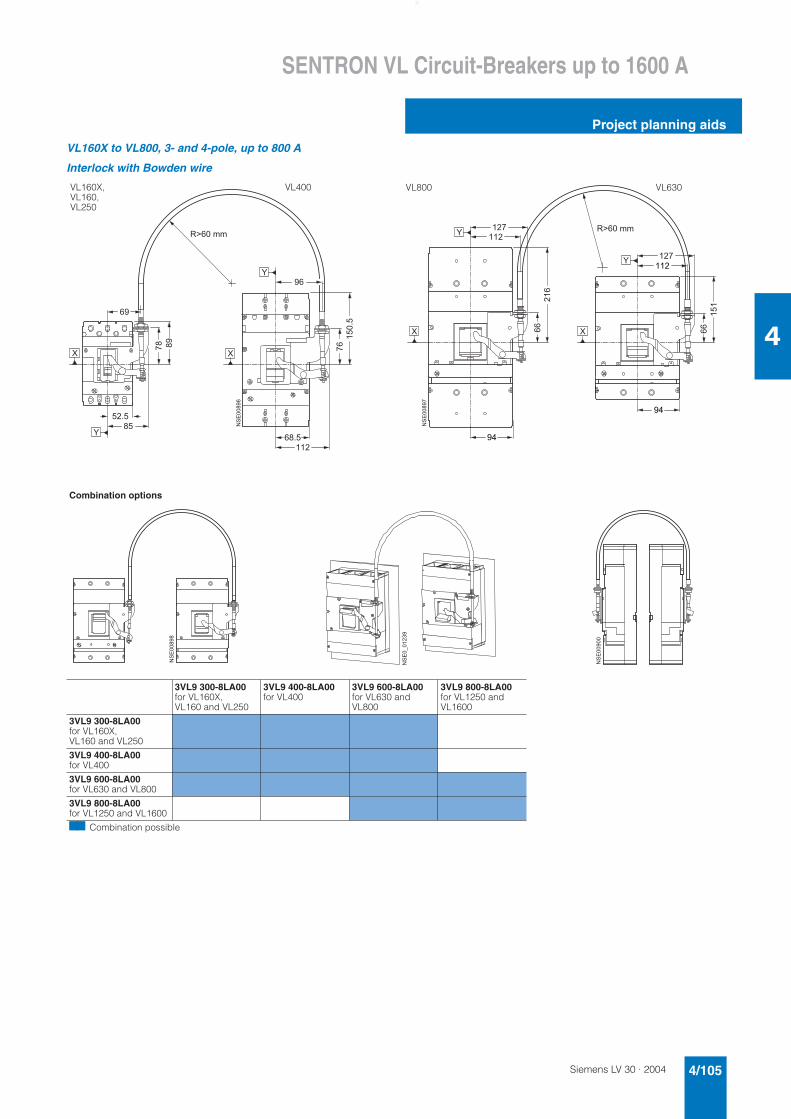
Siemens LV 30 · 2004 4/105
SENTRON VL Circuit-Breakers up to 1600 A
Project planning aids
4
VL160X to VL800, 3- and 4-pole, up to 800 A
Interlock with Bowden wire
Combination options
��
������
�����
��
�������
� �
������
�
�
�������
VL160X,VL160,VL250
VL400
�
��
��
���
���
���
���
��
���
��
���
������
�
�������
VL800 VL630
������
������ ��
��������
3VL9 300-8LA00for VL160X, VL160 and VL250
3VL9 400-8LA00for VL400
3VL9 600-8LA00for VL630 and VL800
3VL9 800-8LA00for VL1250 and VL1600
3VL9 300-8LA00for VL160X, VL160 and VL250
3VL9 400-8LA00for VL400
3VL9 600-8LA00for VL630 and VL800
3VL9 800-8LA00for VL1250 and VL1600
77 Combination possible
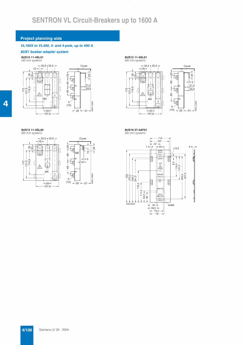
Siemens LV 30 · 20044/106
SENTRON VL Circuit-Breakers up to 1600 A
Project planning aids
4
VL160X to VL400, 3- and 4-pole, up to 400 A
8US1 busbar adapter system
8US10 11-4SL01 (40 mm system)
8US12 11-4SL01 (60 mm system)
8US12 11-4SL00 (60 mm system)
8US19 27-4AF01 (60 mm system)
�����
��������
������
��
������
�
����
�
����
�����
���
����
��
��
��
�����
�� ���������
!"#$
���������
�����
����
�����
���
������
��
���������
��
��
��
��
�
����
����
����
�����
!"#$
���������
�����
����
�����
���
������
���������
��
��
��
��
��
�
��
���
����
�����
!"#$
�%&�
�%&�'�
�����
�����
����
������
�%&��������%&�(� )
&�
�%*�
�%*�
�%&�
�����
����������
�������
�����
������
�����
�����
����������������
� ����������
����
��
�
�%&�'�'�
�������
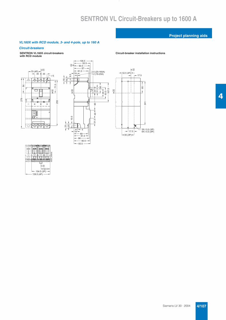
Siemens LV 30 · 2004 4/107
SENTRON VL Circuit-Breakers up to 1600 A
Project planning aids
4
VL160X with RCD module, 3- and 4-pole, up to 160 A
Circuit-breakers
SENTRON VL160X circuit-breakers with RCD module
Circuit-breaker installation instructions
���
���
� �
� �
� � �
� �
� � � �
� � � � �
� � � �
���
��
� � � � �
� � � � � � �
� � � � � � �
�
� � � � � � �� � �
� � � � � � � �
� � � � � � � �
���
���
� � � � �
� � � �
� � � �
� �
� � � � � � � � � � � �
� � � �
�����
����
���
��
���
���
��
� ���
����
���
����
� � � � � �
�
�
��
�� �
���
� � � �
�
� �
����������*
� �
�
� � � �
��
� � � � � � � � � �
� � � � �
�
� � �
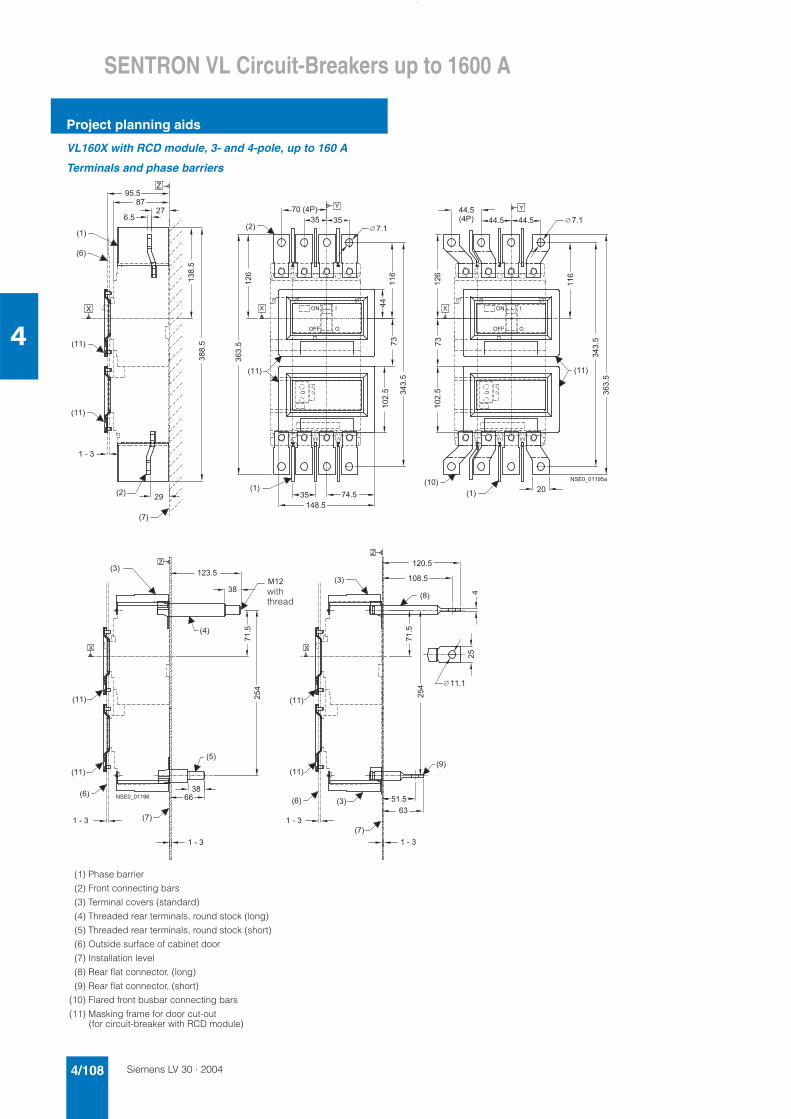
Siemens LV 30 · 20044/108
SENTRON VL Circuit-Breakers up to 1600 A
Project planning aids
4
VL160X with RCD module, 3- and 4-pole, up to 160 A
Terminals and phase barriers
(1) Phase barrier
(2) Front connecting bars
(3) Terminal covers (standard)
(4) Threaded rear terminals, round stock (long)
(5) Threaded rear terminals, round stock (short)
(6) Outside surface of cabinet door
(7) Installation level
(8) Rear flat connector, (long)
(9) Rear flat connector, (short)
(10) Flared front busbar connecting bars
(11) Masking frame for door cut-out (for circuit-breaker with RCD module)
� �
���
� � � � �
� � � � �
� �
�����
� � � �
� � �
� �
� �
� � �
� � �
� �
����
� � �
�����
� � �
� �
� � � �
� � � � � �
��
��
��
����
��
� �
� � � � �
� � � �
���
����
� � �
�
� � �
�
� �
� � �
�
� �
��
���
� � � �
� � �
��
��
��� �
�� � �
�� �
�� � �
� � � � � � � � �
� �
� �
�
�
� � � � � � � �
� � � �
� � � � �
� � � � �
� ���
� ���
� � �
� �
�
� � � �
����
����
� �
� � � �
� � �
�
� � �
�
�
' � �
�
�
� � �
� � �
� � �
� � �
� � �
� � �
� �
� �
� �
� �
� �
� �
� �
� � �
� � �
��
���
� � � � � � � �
�
withthread
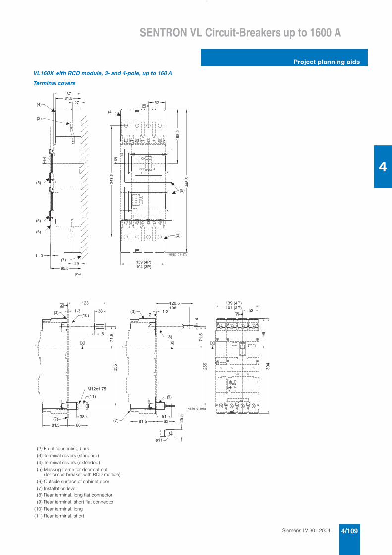
Siemens LV 30 · 2004 4/109
SENTRON VL Circuit-Breakers up to 1600 A
Project planning aids
4
VL160X with RCD module, 3- and 4-pole, up to 160 A
Terminal covers
(2) Front connecting bars
(3) Terminal covers (standard)
(4) Terminal covers (extended)
(5) Masking frame for door cut-out (for circuit-breaker with RCD module)
(6) Outside surface of cabinet door
(7) Installation level
(8) Rear terminal, long flat connector
(9) Rear terminal, short flat connector
(10) Rear terminal, long
(11) Rear terminal, short
���
� � �
� � � � �
� � � �
� �
� � �
0
� � �
� � �
� � �
� � � �
� �
� � �
� � �
� � �
�
�����
� � � � �
� � � � �
� � �
� � �
� � �
����
-
�
�� �
�� � �
� � � � � � � � �
� � �
���
� �� � �
�
�
�
�
� ��
�
��
���
����
)
�
�
� � � � �
� � � � � � �
� � � �
�
� ��
�
��
� �
� �
� � �
�
�
� � �
� �
' � - � � �
� � �
� � �
�
� �
�
� � �
�
�
� � � � � � � � �
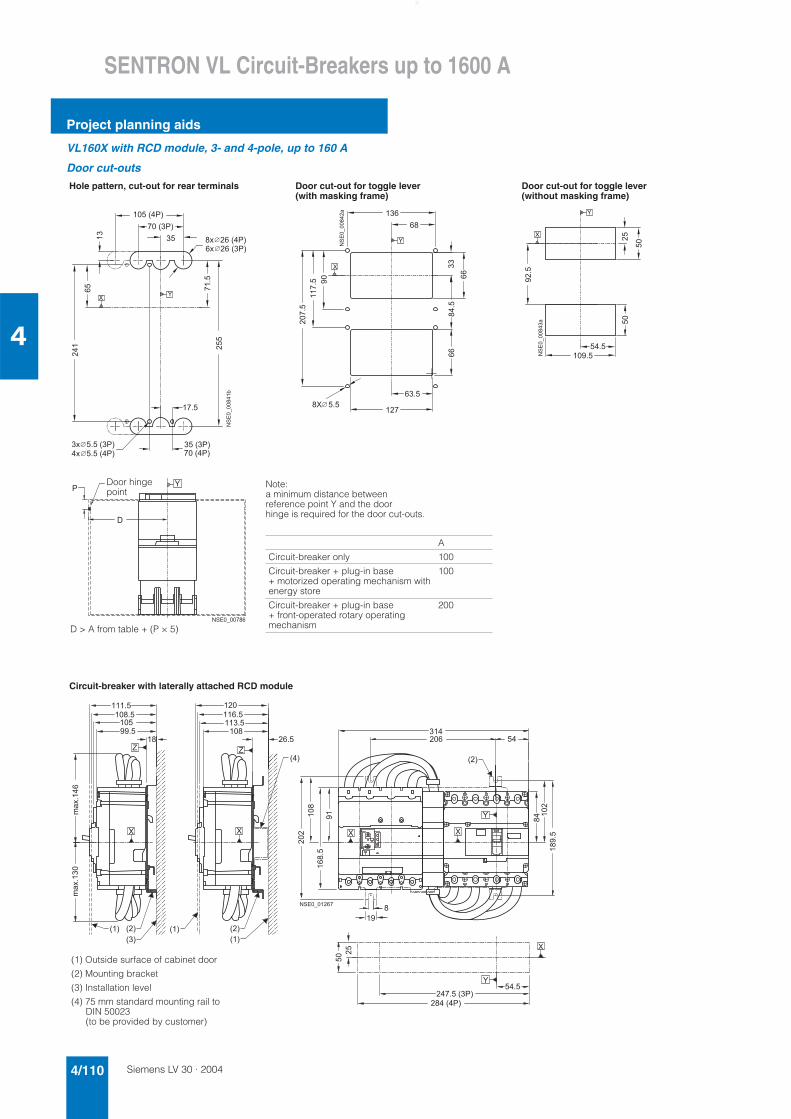
Siemens LV 30 · 20044/110
SENTRON VL Circuit-Breakers up to 1600 A
Project planning aids
4
VL160X with RCD module, 3- and 4-pole, up to 160 A
Door cut-outs
Hole pattern, cut-out for rear terminals Door cut-out for toggle lever (with masking frame)
Door cut-out for toggle lever (without masking frame)
Circuit-breaker with laterally attached RCD module
����
� � � �
� � � �
� - � � � � � � � � � �
- � � � � � � � � �
� - � � � � � � � � �
� - � � � � � � � � � �
� ���
� � � � � �
� � � � �
�
���
��
� �
�
�
��������� *
�
�
� � � � � � ���
�
� � � � � � �
� � �
��
���
� � �
���
� � �
�
�
����������
���
��
���
�
� �
� � � �
�
�
��
�
�
�����������
�
�
�
� � � � � � � � � �
Note:a minimum distance between reference point Y and the door hinge is required for the door cut-outs.
Door hingepoint
D > A from table + (P × 5)
A
Circuit-breaker only 100
Circuit-breaker + plug-in base + motorized operating mechanism with energy store
100
Circuit-breaker + plug-in base + front-operated rotary operating mechanism
200
������
�
���
����
�
�
���
� � � � � � � �
� � � � � � �
������
�
�
�
� �
� �
� �
�
� � �
� � �
�
� �
� �
� �
� �
�
� �
�
�
�
��
�
�
�
�
� � � �
� � �
� � � �
� �
� � � � �
� � � � � � � �
(1) Outside surface of cabinet door
(2) Mounting bracket
(3) Installation level
(4) 75 mm standard mounting rail to DIN 50023 (to be provided by customer)
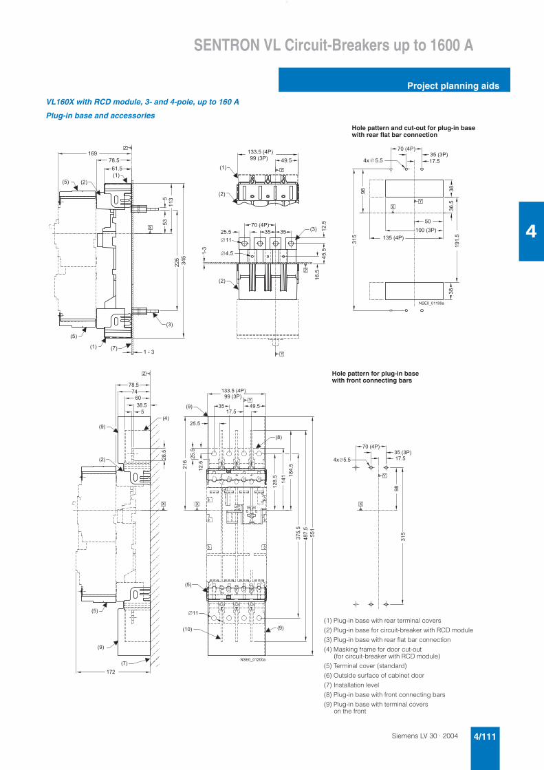
Siemens LV 30 · 2004 4/111
SENTRON VL Circuit-Breakers up to 1600 A
Project planning aids
4
VL160X with RCD module, 3- and 4-pole, up to 160 A
Plug-in base and accessories
Hole pattern and cut-out for plug-in base with rear flat bar connection
� � � � � � �
��
� �
� � � ��
� � �
� � �
� �
� �
� � � � � � � � � �
� � � � � � � �
� �
� �
�
�
� � � � � � �
� � � �
� � �
�
�� �
�
��
� �
�
� � �
� �
� �
�
� �
�
� �� �
���
���
� � � � � � �
� � � � � �
� � �
�� �
��� �
� �
���
� � � � � � �
� � � � � �
�
�
� � � � � � � � �
�
�
� �
��
� � � � � �
� � �
� �
� � � � � � � �
�� �
�� �
����
�
�
� �
��
� � � �
�� �
�
� � �
�
� � �
� � �
�
� �
� � �
� � �
� � �
�
� �
� � �
� �
� � � � � � �
� � � � � �
���
� � �
� �
�
�
�
� � � � � � � � �
� �
� �
� �
� � �
� � �
� � � � � � �
�
� ���
�
(1) Plug-in base with rear terminal covers
(2) Plug-in base for circuit-breaker with RCD module
(3) Plug-in base with rear flat bar connection
(4) Masking frame for door cut-out (for circuit-breaker with RCD module)
(5) Terminal cover (standard)
(6) Outside surface of cabinet door
(7) Installation level
(8) Plug-in base with front connecting bars
(9) Plug-in base with terminal covers on the front
Hole pattern for plug-in base with front connecting bars
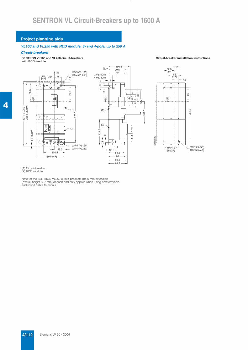
Siemens LV 30 · 20044/112
SENTRON VL Circuit-Breakers up to 1600 A
Project planning aids
4
VL160 and VL250 with RCD module, 3- and 4-pole, up to 250 A
Circuit-breakers
SENTRON VL160 and VL250 circuit-breakers with RCD module
Circuit-breaker installation instructions
(1) Circuit-breaker(2) RCD module
Note for the SENTRON VL250 circuit-breaker: The 5 mm extension (overall height 307 mm) at each end only applies when using box terminals and round cable terminals.
���
���
�
���
���
������� �
����� �
���������
� �������
����
������� �
� ����� �
�� ��
��
��
����
��
���������
��
��
��
����
�
� ��
����
� ����
������ ���� ��� ��
��
��
��
��
� ���
��
��������
��
��
��
� ��� ���
�����
��
����
��������
����
������� �
�
������� �������� �
�
��
��������
�
����������������
��
��� ����
������
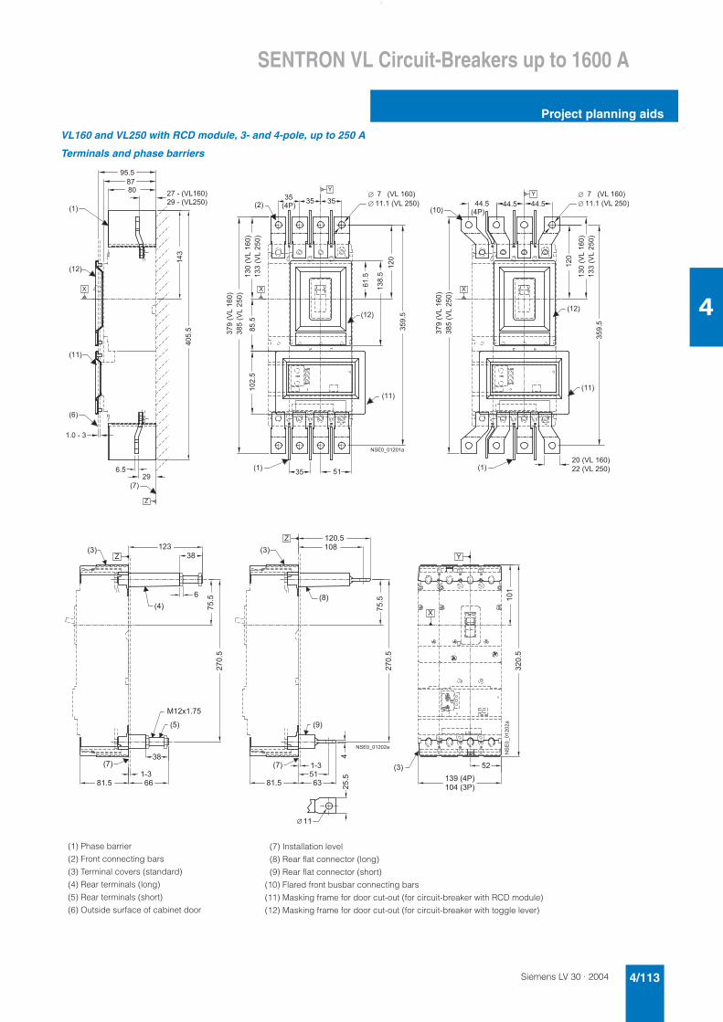
Siemens LV 30 · 2004 4/113
SENTRON VL Circuit-Breakers up to 1600 A
Project planning aids
4
VL160 and VL250 with RCD module, 3- and 4-pole, up to 250 A
Terminals and phase barriers
(1) Phase barrier
(2) Front connecting bars
(3) Terminal covers (standard)
(4) Rear terminals (long)
(5) Rear terminals (short)
(6) Outside surface of cabinet door
� � �
� �
� �
� �
� �
� �
� �
� �
� �
� � �
� �
� �
� �
� � � � � �
� �
�� �
� �
� � � � � � � � � �
� � � � � � � � �
�� � �
� � �
���
� � �
� � �
� �
� � � � �
� � � �
�
� �� �
�� �
��� �
� ��
��
�� ����� ���
� � �
� �� �
��
�
�
� � �
� � � � � � � �
�
�
� � � �
�
� � � � � � � �
�
� � � � � � � � � � � ��
� � � � � � � � � � � �
� � � � � � � � � � � ��
� � � � � � � �
� � � � � � � � � �
������������
�� ����� ���
������������
�
������� ���
�����������
������� ���
�����������
� �
�
� �
���
� �
� �
� �
� �
�
� � � � � � �
� � � � � � �
���
� �
� �
� �
� �
� �
� �
� �
���
�
� � � �
��������
�
�
�
�
� � �
� � �
� �
� � �
� � �
� � �
� � �
� � �
� � �
� � � � � � � �
(7) Installation level
(8) Rear flat connector (long)
(9) Rear flat connector (short)
(10) Flared front busbar connecting bars
(11) Masking frame for door cut-out (for circuit-breaker with RCD module)
(12) Masking frame for door cut-out (for circuit-breaker with toggle lever)
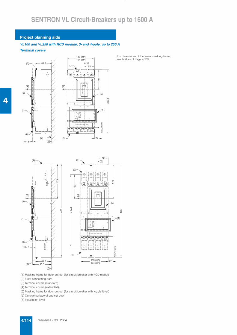
Siemens LV 30 · 20044/114
SENTRON VL Circuit-Breakers up to 1600 A
Project planning aids
4
VL160 and VL250 with RCD module, 3- and 4-pole, up to 250 A
Terminal covers
(1) Masking frame for door cut-out (for circuit-breaker with RCD module)
(2) Front connecting bars
(3) Terminal covers (standard)
(4) Terminal covers (extended)
(5) Masking frame for door cut-out (for circuit-breaker with toggle lever)
(6) Outside surface of cabinet door
(7) Installation level
� � �
�
� �
� �
� � � � � �
���������
� � �
�
���
��
� � � � � � �
� � � � � � �
� � �
� � �
� � �
� �
� �
� � �
�
�
�
For dimensions of the lower masking frame, see bottom of Page 4/109.
� � �
� � �
� � �
� �
� � �
� �
� �
� � � � � �
� � �
� � �
�� �
���
� �� �
��
� � � � � � �
� � � � � � �
���
��
�
� � �
� �
� �
���������
�
�
�
�
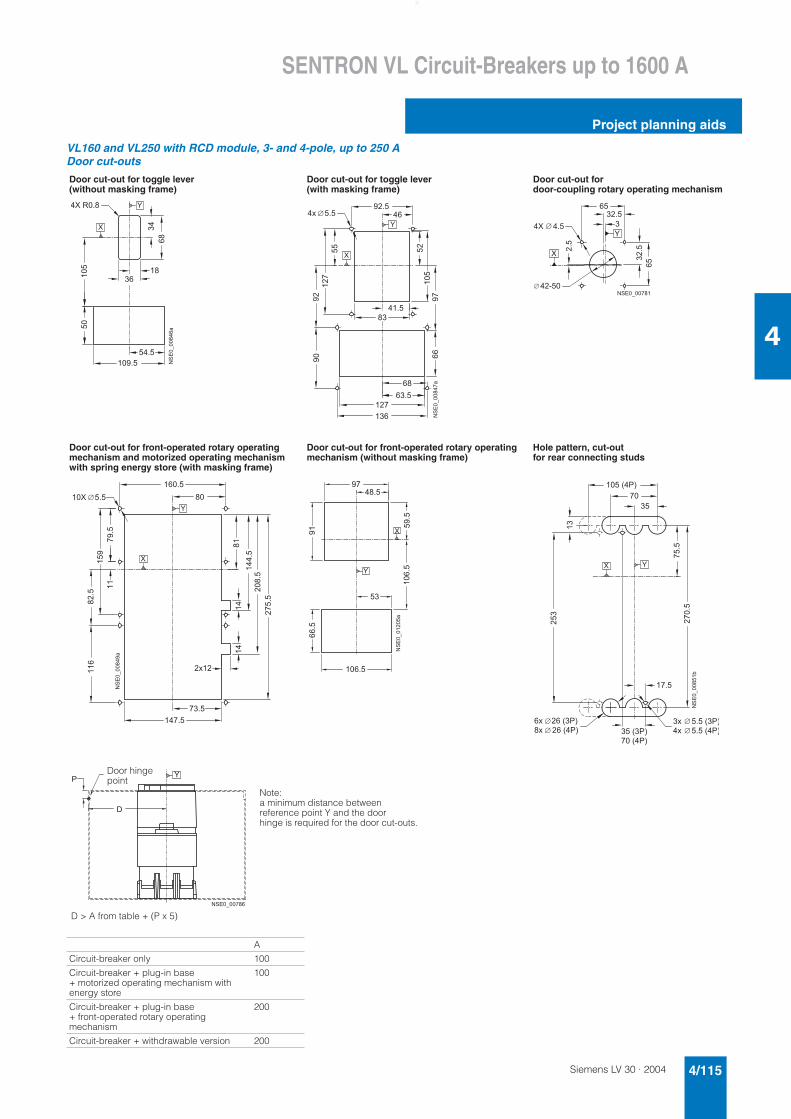
Siemens LV 30 · 2004 4/115
SENTRON VL Circuit-Breakers up to 1600 A
Project planning aids
4
VL160 and VL250 with RCD module, 3- and 4-pole, up to 250 ADoor cut-outs
Door cut-out for toggle lever (without masking frame)
Door cut-out for toggle lever (with masking frame)
Door cut-out for door-coupling rotary operating mechanism
Door cut-out for front-operated rotary operating mechanism and motorized operating mechanism with spring energy store (with masking frame)
Door cut-out for front-operated rotary operating mechanism (without masking frame)
Hole pattern, cut-out for rear connecting studs
A
Circuit-breaker only 100
Circuit-breaker + plug-in base + motorized operating mechanism with energy store
100
Circuit-breaker + plug-in base + front-operated rotary operating mechanism
200
Circuit-breaker + withdrawable version 200
� � � � � � �
� �
� � � �
�
�
� �
��
�
��
�����������
�
�
���
��
�
��
� �
��
� � �
�
� �
� �
� � �
� �
�
� �
��
� � �
� � �
�
�
�
�����������
�
� � �
� � � �
� �
� �
� �
�� �
� �
� �
� � � � � � � � �
�
�
� � �
��
�
�� �
��� �
�
���
� � �
� � �
�
� �
� � � �
� � �
��
� �
�
�
�����������
�
�
���
�
��� �
��� �
� � � �
�
� � �
� � � �
��
�
�
������� �
� �
� � � � � �
��
� �
� � ��� �
� � � � � �
�
�
� � �
� � �
� �
� � � � � �
� �
� � � � � �
� � � � � � � �
��������
� � � � � �
� � � � � � �
�
�
�
� � � � � � � � � �
Note:a minimum distance between reference point Y and the door hinge is required for the door cut-outs.
Door hingepoint
D > A from table + (P x 5)
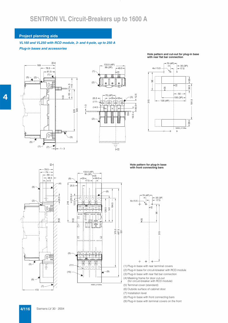
Siemens LV 30 · 20044/116
SENTRON VL Circuit-Breakers up to 1600 A
Project planning aids
4
VL160 and VL250 with RCD module, 3- and 4-pole, up to 250 A
Plug-in bases and accessories
� � � � � � �
��
� �
� � � ��
� � �
� � �
� �
� �
� � � � � � � � � �
� � � � � � � �
� �
� �
�
�
� � � � � � �
� � � �
� � �
�
�� �
�
��
� �
�
� � �
� �
� �
�
� �
�
� �� �
���
���
� � � � � � �
� � � � � �
� � �
�� �
��� �
� �
���
� � � � � � �
� � � � � �
�
�
� � � � � � � � �
�
�
� �
��
Hole pattern and cut-out for plug-in base with rear flat bar connection
� � � � � �
� � �
� �
� � � � � � � �
�� �
�� �
����
�
�
� �
��
� � � �
�� �
�
� � �
�
� � �
� � �
�
� �
� � �
� � �
� � �
�
� �
� � �
� �
� � � � � � �
� � � � � �
���
� � �
� �
�
�
�
� � � � � � � � �
� �
� �
� �
� � �
� � �
� � � � � � �
�
� ���
�
Hole pattern for plug-in base with front connecting bars
(1) Plug-in base with rear terminal covers
(2) Plug-in base for circuit-breaker with RCD module
(3) Plug-in base with rear flat bar connection
(4) Masking frame for door cut-out (for circuit-breaker with RCD module)
(5) Terminal cover (standard)
(6) Outside surface of cabinet door
(7) Installation level
(8) Plug-in base with front connecting bars
(9) Plug-in base with terminal covers on the front
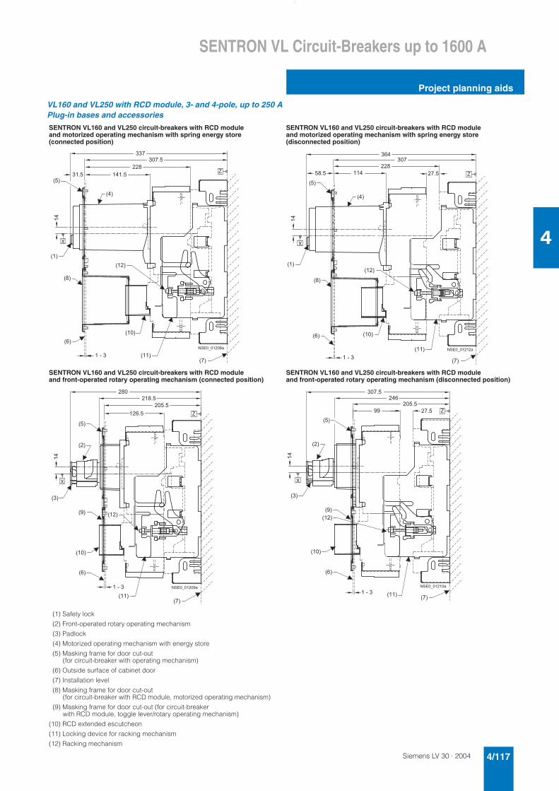
Siemens LV 30 · 2004 4/117
SENTRON VL Circuit-Breakers up to 1600 A
Project planning aids
4
VL160 and VL250 with RCD module, 3- and 4-pole, up to 250 APlug-in bases and accessories
SENTRON VL160 and VL250 circuit-breakers with RCD module and motorized operating mechanism with spring energy store (connected position)
SENTRON VL160 and VL250 circuit-breakers with RCD module and motorized operating mechanism with spring energy store (disconnected position)
SENTRON VL160 and VL250 circuit-breakers with RCD module and front-operated rotary operating mechanism (connected position)
SENTRON VL160 and VL250 circuit-breakers with RCD module and front-operated rotary operating mechanism (disconnected position)
(1) Safety lock
(2) Front-operated rotary operating mechanism
(3) Padlock
(4) Motorized operating mechanism with energy store
(5) Masking frame for door cut-out (for circuit-breaker with operating mechanism)
(6) Outside surface of cabinet door
(7) Installation level
(8) Masking frame for door cut-out (for circuit-breaker with RCD module, motorized operating mechanism)
(9) Masking frame for door cut-out (for circuit-breaker with RCD module, toggle lever/rotary operating mechanism)
(10) RCD extended escutcheon
(11) Locking device for racking mechanism
(12) Racking mechanism
� �
� � �
� � �
� � �
� �
� �
� � �
�
� � �
� �
� � � �
�
� � � �
��
� � � �
� � � � �
�
� � � � � � � � �
� � �
� �
� � �
� � �
� �
� �
� �
� � �
� � �
� � � �
��
� � �
� � �
�
�
� � � �
� � �
� � � � � � �
�
� �
� � �
� � �
� � �
� � �
� �
� � �
� �
� �
� � � �
��
� �
� �
� � �
� �
� � � � � � � � �
�
�
� � �
� �
� � �
� � �
� � �
� �
� � �
� �
� �
� �
��
� �
� � � �
� � �
� � �
� � � �
� � � � � � � �
�
�
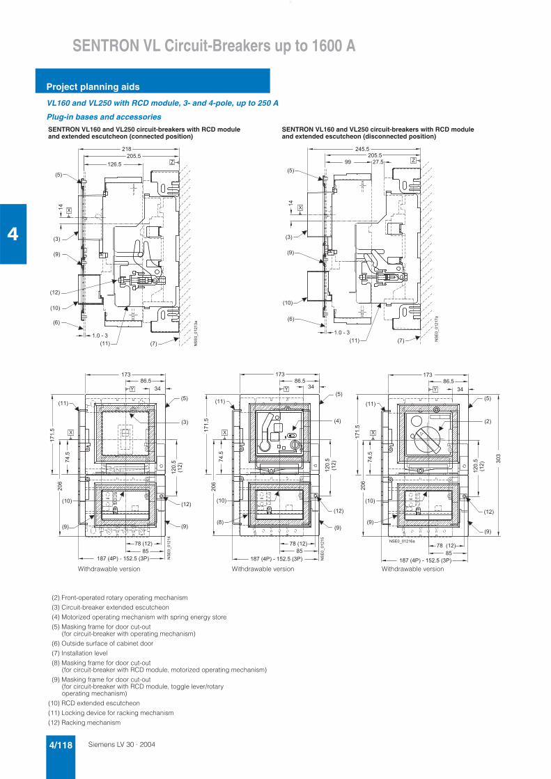
Siemens LV 30 · 20044/118
SENTRON VL Circuit-Breakers up to 1600 A
Project planning aids
4
VL160 and VL250 with RCD module, 3- and 4-pole, up to 250 A
Plug-in bases and accessories
SENTRON VL160 and VL250 circuit-breakers with RCD module and extended escutcheon (connected position)
SENTRON VL160 and VL250 circuit-breakers with RCD module and extended escutcheon (disconnected position)
(2) Front-operated rotary operating mechanism
(3) Circuit-breaker extended escutcheon
(4) Motorized operating mechanism with spring energy store
(5) Masking frame for door cut-out (for circuit-breaker with operating mechanism)
(6) Outside surface of cabinet door
(7) Installation level
(8) Masking frame for door cut-out (for circuit-breaker with RCD module, motorized operating mechanism)
(9) Masking frame for door cut-out (for circuit-breaker with RCD module, toggle lever/rotary operating mechanism)
(10) RCD extended escutcheon
(11) Locking device for racking mechanism
(12) Racking mechanism
� �
� � �
� � �
� � �
� � �
� �
� � �
� �
�
� � � � � �
��
� �
�
� � �
�
��������
� � �
� � �
� � �
� � �
� � � � �
� �
� � � � � �
��
� � �
� �
� �
��������
�
�� �
� �
� � �
� � � � � �
� �
� � �
� �
��� �
�� �
�� �
��
� � � � � � � � � � � � � � � �
� � � � �
� �
���
� � � �
� � �
� � ��
�������
�
� � �
� � �
� �
� � �
� �
� � �
� �
� � � � �
� � � � � � � � � � � � � � � �
���
�� �
��� �
�� �
��
� �
� � �
� � � �
� � �
������
�
�
� � �
� � �
� �
� � �
� �
� �
� �
� � � � � � � � � � � � � � � �
� � � � � �
� �
���
�� �
��� �
� � �
� � � �
� � �
�� �
��
�
� � � � � � � �
�
���
Withdrawable version Withdrawable version Withdrawable version
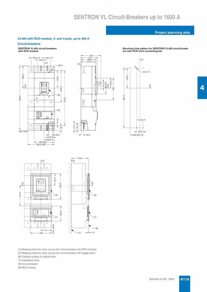
Siemens LV 30 · 2004 4/119
SENTRON VL Circuit-Breakers up to 1600 A
Project planning aids
4
VL400 with RCD module, 3- and 4-pole, up to 400 A
Circuit-breakers
SENTRON VL400 circuit-breakers with RCD module
Mounting hole pattern for SENTRON VL400 circuit-break-ers with RCD front connecting bar
(1) Masking frame for door cut-out (for circuit-breaker with RCD module)
(5) Masking frame for door cut-out (for circuit-breaker with toggle lever)
(6) Outside surface of cabinet door
(7) Installation level
(8) Circuit-breaker
(9) RCD module
� � �
� � �
� � � �
� � � � � � � �
� � � � � � �
� � �
�
� � �
� �
����
��
�
��
� � �
� � � � � �
�
�
�� �
�
! " " !
! � #
� � � � � � � � �
�
� �
���
��
�
��
�
���
� �
�
� � �
� �
� � � � � � �
� � �
����
���
�
�
� � � � � �
� �
�
�
� �
�� �
� �
�� �
�� �
��� �
�
! " "
! �
!
#
�������� ��
� �
� � �
� � �
� �
� �
�
�
� �
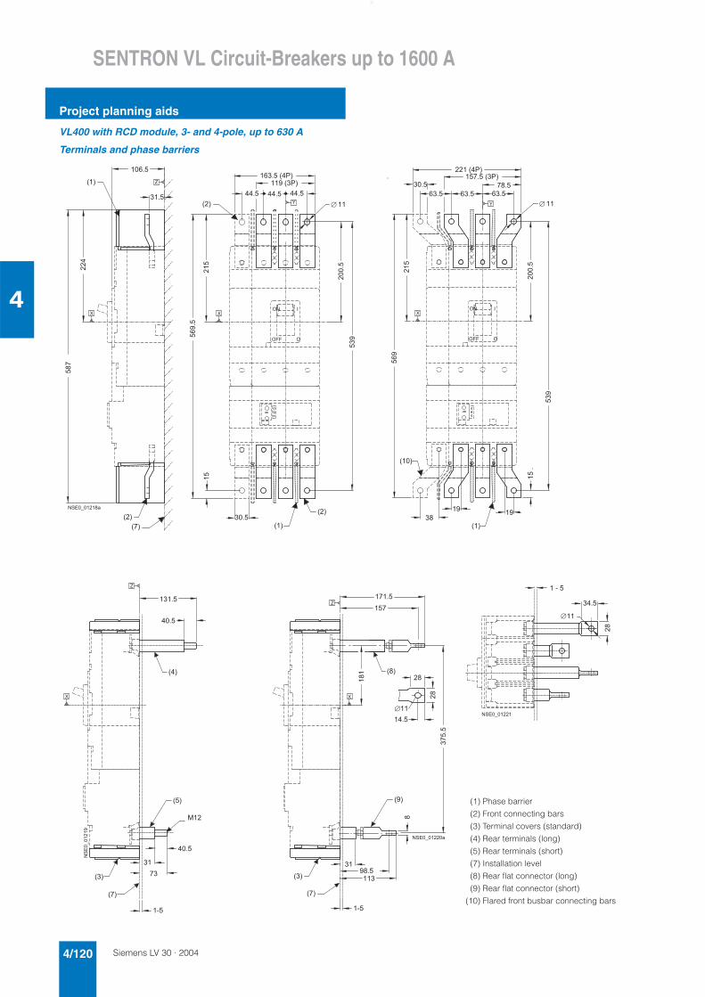
Siemens LV 30 · 20044/120
SENTRON VL Circuit-Breakers up to 1600 A
Project planning aids
4
VL400 with RCD module, 3- and 4-pole, up to 630 A
Terminals and phase barriers
��
� �
� � �
�
�
� � � �
� �
� �
�
� � � � � � � �
� � �
�
� �
� �
�
���
� �
� � �
��
���
� � � � � �
� � � � � � � �
� � �
�
� � � �
! " "
! �
!
#
� � � � � � �
�
� �
� �
� � �
�
��
� � �
�
� � �
� � � � �
� � �
��
�
��
���
� � �
�
� � �
! " "
! �
!
#
� �
�
� � �
� � �
� � �
�
�
� �
�
�
� � �
� � �
� �
�������
�
� � �
� � �
� � �
�
�
� � �
�
�
� � �
� �
�
�
�
� �
�
�� �
� � � � � � � �
�
�
� � �
� � �
�
� � � � � �
(1) Phase barrier
(2) Front connecting bars
(3) Terminal covers (standard)
(4) Rear terminals (long)
(5) Rear terminals (short)
(7) Installation level
(8) Rear flat connector (long)
(9) Rear flat connector (short)
(10) Flared front busbar connecting bars
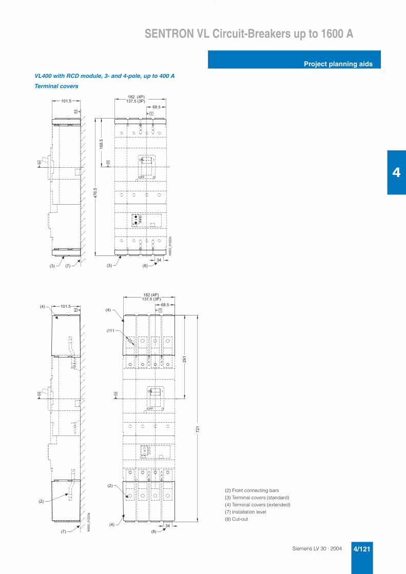
Siemens LV 30 · 2004 4/121
SENTRON VL Circuit-Breakers up to 1600 A
Project planning aids
4
VL400 with RCD module, 3- and 4-pole, up to 400 A
Terminal covers
� � �� � �
�
�
� �
�������
� � �
� � � � � � �
� � � � � � � �
����
�
���
�
� � �
! �
! " "
#
!
� �
� � �
� �
�
� � � � �
�
� � �
��������
� � � � � �
� � � � � � � �
� � �
� �
�
� � �
�
�
�
�
� � �
! " "
! �
!
#
� � �
� �
(2) Front connecting bars
(3) Terminal covers (standard)
(4) Terminal covers (extended)
(7) Installation level
(8) Cut-out
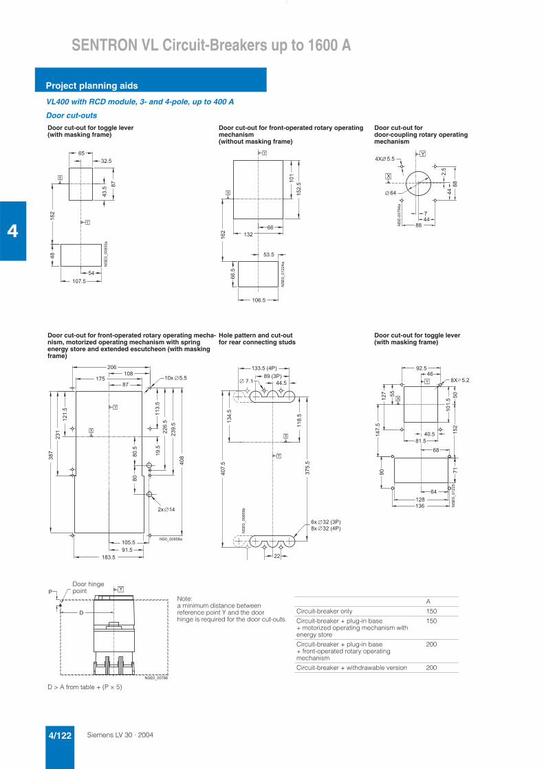
Siemens LV 30 · 20044/122
SENTRON VL Circuit-Breakers up to 1600 A
Project planning aids
4
VL400 with RCD module, 3- and 4-pole, up to 400 A
Door cut-outs
Door cut-out for toggle lever (with masking frame)
Door cut-out for front-operated rotary operating mechanism (without masking frame)
Door cut-out for door-coupling rotary operating mechanism
Door cut-out for front-operated rotary operating mecha-nism, motorized operating mechanism with spring energy store and extended escutcheon (with masking frame)
Hole pattern and cut-out for rear connecting studs
Door cut-out for toggle lever (with masking frame)
Note:a minimum distance between reference point Y and the door hinge is required for the door cut-outs.
A
Circuit-breaker only 150
Circuit-breaker + plug-in base + motorized operating mechanism with energy store
150
Circuit-breaker + plug-in base + front-operated rotary operating mechanism
200
Circuit-breaker + withdrawable version 200
D > A from table + (P × 5)
�
�
� � �
�
��
�
� �
�
���
��
�������� �
�
�
���
� �
� � �
�
� �
�
�
�
��������
��
���
�
����
��
���
�
���� ����
���
��
�
� � �
� �
� �
�
��
�
�
� �
� �
� �
�
��
���
� � � � � � �
� � � � � � � � �
���
�
�
���
��
�
��
���
�� �
����
� � � � � � � � � � � �
�
���
�
�������� �
� � � � �
� � � � � � �
� � � � � � � �
��
� � � � � � � � � � � �
�
�
��� �
� � � �
� � �
�
�� � ��
�
���
��
� �
� � �
� � �
��
� � �
� � �
� �
� � �
� ��
������
�
�
�
� � � � � � � � � �
Door hingepoint
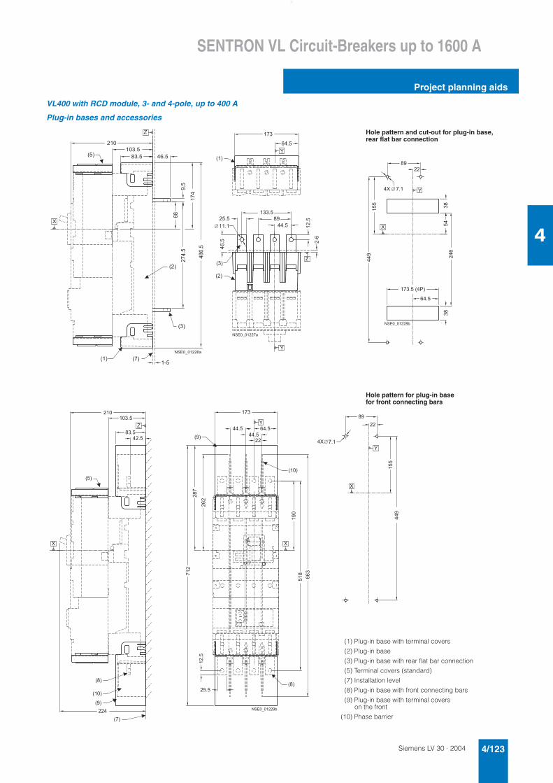
Siemens LV 30 · 2004 4/123
SENTRON VL Circuit-Breakers up to 1600 A
Project planning aids
4
VL400 with RCD module, 3- and 4-pole, up to 400 A
Plug-in bases and accessories
� � �
��� �
� � �� �
� �
� �
�� �
��
� � � �
� �
� �
� � � � � � �
��
�
�
� � � � � � � �
����
Hole pattern and cut-out for plug-in base, rear flat bar connection
� �
� � � �
� �
���
� � �
��
�
� �
� � � �
� �
� �
� � �
� � � �
�
�
� � � � � � � �
�
� � � � � � � �
����
�
��
� � � �
���
���
�
� �
� � � � �
�
� � � � � � �
� � �
� � �
� � �
� � �
� �
� � � �
� � � �
� �
� � �
� �
� �
� � �
��
��
���
� � � �
�����
� � �
� �
� � � �� � � �
� � �
���
�
����
� �
! �#
! " "!
�
��
�
�
� � � �
�
� � � � � � �
� �
Hole pattern for plug-in base for front connecting bars
(1) Plug-in base with terminal covers
(2) Plug-in base
(3) Plug-in base with rear flat bar connection
(5) Terminal covers (standard)
(7) Installation level
(8) Plug-in base with front connecting bars
(9) Plug-in base with terminal covers on the front
(10) Phase barrier
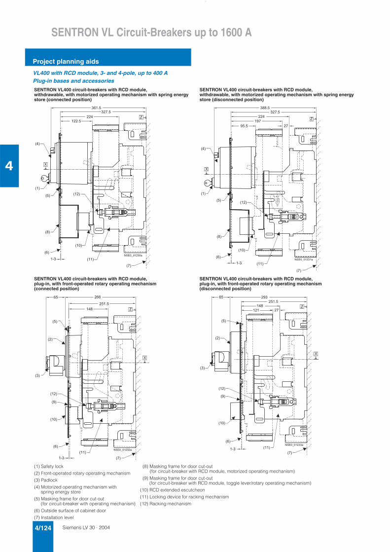
Siemens LV 30 · 20044/124
SENTRON VL Circuit-Breakers up to 1600 A
Project planning aids
4
VL400 with RCD module, 3- and 4-pole, up to 400 APlug-in bases and accessories
SENTRON VL400 circuit-breakers with RCD module, withdrawable, with motorized operating mechanism with spring energy store (connected position)
SENTRON VL400 circuit-breakers with RCD module, withdrawable, with motorized operating mechanism with spring energy store (disconnected position)
SENTRON VL400 circuit-breakers with RCD module,plug-in, with front-operated rotary operating mechanism (connected position)
SENTRON VL400 circuit-breakers with RCD module,plug-in, with front-operated rotary operating mechanism (disconnected position)
(1) Safety lock
(2) Front-operated rotary operating mechanism
(3) Padlock
(4) Motorized operating mechanism with spring energy store
(5) Masking frame for door cut-out (for circuit-breaker with operating mechanism)
(6) Outside surface of cabinet door
(7) Installation level
(8) Masking frame for door cut-out (for circuit-breaker with RCD module, motorized operating mechanism)
(9) Masking frame for door cut-out (for circuit-breaker with RCD module, toggle lever/rotary operating mechanism)
(10) RCD extended escutcheon
(11) Locking device for racking mechanism
(12) Racking mechanism
� � �
� �
� � �
� � �
� �
� � �
� �
� �
� �
� �
� � �
� �
� � �
� � � �
�
�
� � � � � � � � �
� � �
� � �
� � �
� � �
� � �
� �
� �
� �
� �
� � �
� � � � �
� � � �
� � � �
� � �
� �
�
�
� � � � � � � �
� �
� � �
� �
� � �
� � �
� � �
� �
� � �
� �
� �
� � �
�
� �
� � �
�
� � � � � � � �
�
� � �
� � �� �
� � �
� � �
� � �
� � �
� �
� �
� �
� � �
�
� � �
� �
� � �
�
�
� � � � � � � � �
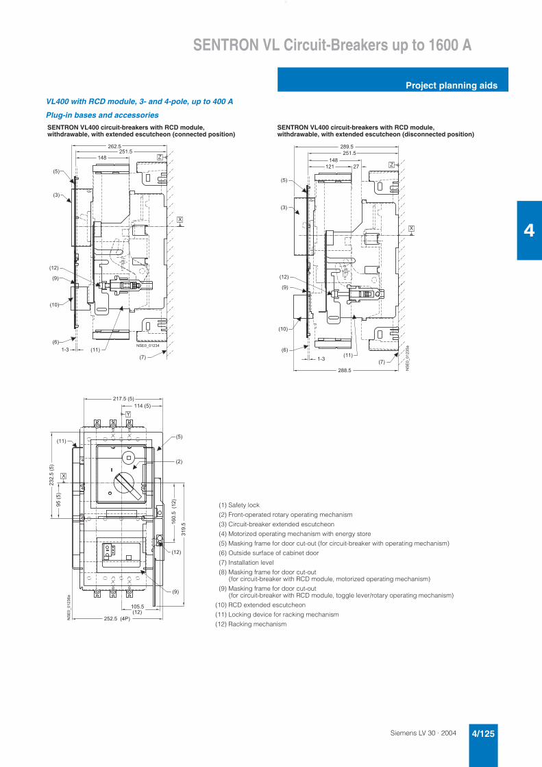
Siemens LV 30 · 2004 4/125
SENTRON VL Circuit-Breakers up to 1600 A
Project planning aids
4
VL400 with RCD module, 3- and 4-pole, up to 400 A
Plug-in bases and accessories
SENTRON VL400 circuit-breakers with RCD module, withdrawable, with extended escutcheon (connected position)
SENTRON VL400 circuit-breakers with RCD module, withdrawable, with extended escutcheon (disconnected position)
(1) Safety lock
(2) Front-operated rotary operating mechanism
(3) Circuit-breaker extended escutcheon
(4) Motorized operating mechanism with energy store
(5) Masking frame for door cut-out (for circuit-breaker with operating mechanism)
(6) Outside surface of cabinet door
(7) Installation level
(8) Masking frame for door cut-out (for circuit-breaker with RCD module, motorized operating mechanism)
(9) Masking frame for door cut-out (for circuit-breaker with RCD module, toggle lever/rotary operating mechanism)
(10) RCD extended escutcheon
(11) Locking device for racking mechanism
(12) Racking mechanism
� � � �
� � �
� �
� �
� � �
� � �
� � �
� � �
� � �
� �
� � �
�
�
� � � � � � � �
� � � �
�
� �
� � �
� � �
� � �
� �
� �
� � �
� � �
� �
�
� � �
� �
�
�
������� �
� � �
� � � � � � �
� � �
� �
� � �
�� �� �
� �� �
��� ����
� �
� �
� �
� � � � �
� � � �
� �
�
�
���������
���
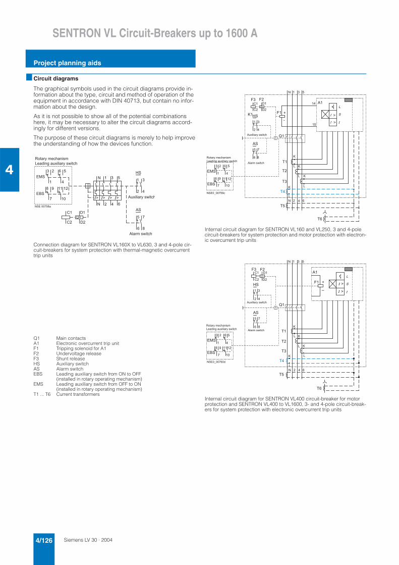
Siemens LV 30 · 20044/126
SENTRON VL Circuit-Breakers up to 1600 A
Project planning aids
4
■ Circuit diagrams
The graphical symbols used in the circuit diagrams provide in-formation about the type, circuit and method of operation of the equipment in accordance with DIN 40713, but contain no infor-mation about the design.
As it is not possible to show all of the potential combinations here, it may be necessary to alter the circuit diagrams accord-ingly for different versions.
The purpose of these circuit diagrams is merely to help improvethe understanding of how the devices function.
Connection diagram for SENTRON VL160X to VL630, 3 and 4-pole cir-cuit-breakers for system protection with thermal-magnetic overcurrent trip units
Internal circuit diagram for SENTRON VL160 and VL250, 3 and 4-pole circuit-breakers for system protection and motor protection with electron-ic overcurrent trip units
Internal circuit diagram for SENTRON VL400 circuit-breaker for motor protection and SENTRON VL400 to VL1600, 3- and 4-pole circuit-break-ers for system protection with electronic overcurrent trip units
Q1 Main contactsA1 Electronic overcurrent trip unitF1 Tripping solenoid for A1F2 Undervoltage releaseF3 Shunt releaseHS Auxiliary switchAS Alarm switchEBS Leading auxiliary switch from ON to OFF
(installed in rotary operating mechanism)EMS Leading auxiliary switch from OFF to ON
(installed in rotary operating mechanism)T1 ... T6 Current transformers
��
������
��
��� ����
�
�
�
�
���
����
�
���
��
��
�
��
�
�
�
�
�
�
�
�
�� �� ��
��
�
�
�
�
��
�
�
�
�
!"�#$%&'(�)*+%�&�,*)-�./*0*�#$+1*"'(
�0�#%+1*"'(
�./*0*�#$+1*"'(
$
�
��
$
�
$
�
% �
%
%
% �
�
$
�
�
�
�
" " �
&
&
'
"
�
�
(
�
)
� � � � � � � � � *
$
�
�
�
� � �
� + � �
�
�
�
) �
�
�
�
, �
�
�
%
% �
� - . � / 0 � � 1 * 2 � 3 4 5 �
� 1 � 6 4 3 7 � � 8 � 4 9 4 � / 0 � 5 : 4 . * 2
) 9 � / � � 5 : 4 . * 2
) 8 � 4 9 4 � / 0 � 5 : 4 . * 2
�
$
" � "
%
% �
% �
$
�
%
�
�
$
�
'
��
�
�
$
)
"
�
(
� � � � � � � � � � 6
�
� &
&
;
;
�
�
�
� � �
� + �
�
�
�
�
) �
�
�
�
, �
�
�
%
% �
� - . � / 0 � � 1 * 2 � 3 4 5 �
� 1 � 6 4 3 7 � � 8 � 4 9 4 � / 0 � 5 : 4 . * 2) 9 � / � � 5 : 4 . * 2
) 8 � 4 9 4 � / 0 � 5 : 4 . * 2
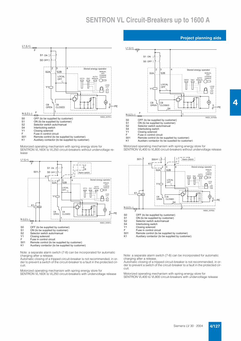
Siemens LV 30 · 2004 4/127
SENTRON VL Circuit-Breakers up to 1600 A
Project planning aids
4
Motorized operating mechanism with spring energy store for SENTRON VL160X to VL250 circuit-breakers without undervoltage re-lease
Note: a separate alarm switch (7-8) can be incorporated for automatic charging after a release. Automatic closing of a tripped circuit-breaker is not recommended, in or-der to prevent a switch of the circuit-breaker to a fault in the protected cir-cuit.
Motorized operating mechanism with spring energy store for SENTRON VL160X to VL250 circuit-breakers with undervoltage release
Motorized operating mechanism with spring energy store for SENTRON VL400 to VL800 circuit-breakers without undervoltage release
Note: a separate alarm switch (7-8) can be incorporated for automatic charging after a release.Automatic closing of a tripped circuit-breaker is not recommended, in or-der to prevent a switch of the circuit-breaker to a fault in the protected cir-cuit.
Motorized operating mechanism with spring energy store for SENTRON VL400 to VL800 circuit-breakers with undervoltage release
� � � � < � � �
� �
� � � � ( �
� )
� �
�
� �
� +
�
� � � � � � � � � *
"
"
�
& +
! � � �
& +
& � ! � � �
� ! & ) �
! " "
� . - / 1 6 � 1 3 1 / 7 0 � - = 1 / � . - /
! " " > � ! � >
) ? % ! >
� ) � ? ) �
� ) � ? ) �
! " " >
& , ) � @ �
, ) � � � �
� ! & $
! ? %
! " "
! �
� �
�
�
� �
�
"
� �
$
! " " � � . - � 1 � 5 8 = = 9 4 1 6 � 0 � * 8 5 . - � 1 / �
! � � � . - � 1 � 5 8 = = 9 4 1 6 � 0 � * 8 5 . - � 1 / �
� 1 9 1 * . - / � 5 : 4 . * 2 � � 8 . - > � � 3 8 � 9
# 3 . 1 / 9 - * A 4 3 7 � 5 : 4 . * 2
& 9 - 5 4 3 7 � 5 - 9 1 3 - 4 6
" 8 5 1 � 4 3 � * - 3 . / - 9 � * 4 / * 8 4 .
� 1 � - . 1 � * - 3 . / - 9 � � . - � 1 � 5 8 = = 9 4 1 6 � 0 � * 8 5 . - � 1 / �
) 8 � 4 9 4 � / 0 � * - 3 . � * . - / � � . - � 1 � 5 8 = = 9 4 1 6 � 0 � * 8 5 . - � 1 / �
� � � � ( �
� � � � < � � �
$
� �
� )
�
� �
$
� �
� +
� �
�
�
�
� � � � � � � � *
"
"
�
& +
! � � �
& +
& � ! � � �
� . - / 1 6 � 1 3 1 / 7 0 � - = 1 / � . - /
! " " > � ! � >
) ? % ! >
� ) � ? ) �
� ) � ? ) �
! " " >
& , ) � @ �
, ) � � � �
� ! & $
! ? %
! " "
! �
� ! & ) �
! " "
) 9 � / � � 5 : 4 . * 2
� �
�
�
�
"
� �
$
! " " � � . - � 1 � 5 8 = = 9 4 1 6 � 0 � * 8 5 . - � 1 / �
! � � � . - � 1 � 5 8 = = 9 4 1 6 � 0 � * 8 5 . - � 1 / �
� 1 9 1 * . - / � 5 : 4 . * 2 � � 8 . - > � � 3 8 � 9
& 9 - 5 4 3 7 � 5 - 9 1 3 - 4 6
" 8 5 1 � 4 3 � * - 3 . / - 9 � * 4 / * 8 4 .
� 1 � - . 1 � * - 3 . / - 9 � � . - � 1 � 5 8 = = 9 4 1 6 � 0 � * 8 5 . - � 1 / �
) 8 � 4 9 4 � / 0 � * - 3 . � * . - / � � . - � 1 � 5 8 = = 9 4 1 6 � 0 � * 8 5 . - � 1 / �
� �
� � � � < � � �
� �
� � � � ( �
�
� )
� +
� �
� �
� � � � � � � � �
�
"
"
�& +
! � � �
& +
& � ! � � �
� . - / 1 6 � 1 3 1 / 7 0 � - = 1 / � . - /
! " " > � ! � >
) ? % ! >
� ) � ? ) �
� ) � ? ) �
! " " >
& , ) � @ �
, ) � � � �
� ! & $
! ? %
! " "
! �
� ! & ) �
! " "
� �
�
�
� �
�
"
� �
$
! " " � � . - � 1 � 5 8 = = 9 4 1 6 � 0 � * 8 5 . - � 1 / �
! � � � . - � 1 � 5 8 = = 9 4 1 6 � 0 � * 8 5 . - � 1 / �
� 1 9 1 * . - / � 5 : 4 . * 2 � � 8 . - > � � 3 8 � 9
# 3 . 1 / 9 - * A 4 3 7 � 5 : 4 . * 2
& 9 - 5 4 3 7 � 5 - 9 1 3 - 4 6
" 8 5 1 � 4 3 � * - 3 . / - 9 � * 4 / * 8 4 .
� 1 � - . 1 � * - 3 . / - 9 � � . - � 1 � 5 8 = = 9 4 1 6 � 0 � * 8 5 . - � 1 / �
) 8 � 4 9 4 � / 0 � * - 3 . � * . - / � � . - � 1 � 5 8 = = 9 4 1 6 � 0 � * 8 5 . - � 1 / �
� �
� � � � < � � �
"
� �
$
� �
� )
� +
� �
�
� �
� � � � � � � � � � *
$
�
�& +
! � � �
& +
& � ! � � �
� ! & ) �
! " "
� . - / 1 6 � 1 3 1 / 7 0 � - = 1 / � . - /
! " " > � ! � >
) ? % ! >
� ) � ? ) �
� ) � ? ) �
! " " >
& , ) � @ �
, ) � � � �
� ! & $
! ? %
! " " ) 9 � / � � 5 : 4 . * 2
� �
�
�
� �
�
"
� �
$
! " " � � . - � 1 � 5 8 = = 9 4 1 6 � 0 � * 8 5 . - � 1 / �
! � � � . - � 1 � 5 8 = = 9 4 1 6 � 0 � * 8 5 . - � 1 / �
� 1 9 1 * . - / � 5 : 4 . * 2 � � 8 . - > � � 3 8 � 9
# 3 . 1 / 9 - * A 4 3 7 � 5 : 4 . * 2
& 9 - 5 4 3 7 � 5 - 9 1 3 - 4 6
" 8 5 1 � 4 3 � * - 3 . / - 9 � * 4 / * 8 4 .
� 1 � - . 1 � * - 3 . / - 9 � � . - � 1 � 5 8 = = 9 4 1 6 � 0 � * 8 5 . - � 1 / �
) 8 � 4 9 4 � / 0 � * - 3 . � * . - / � � . - � 1 � 5 8 = = 9 4 1 6 � 0 � * 8 5 . - � 1 / �
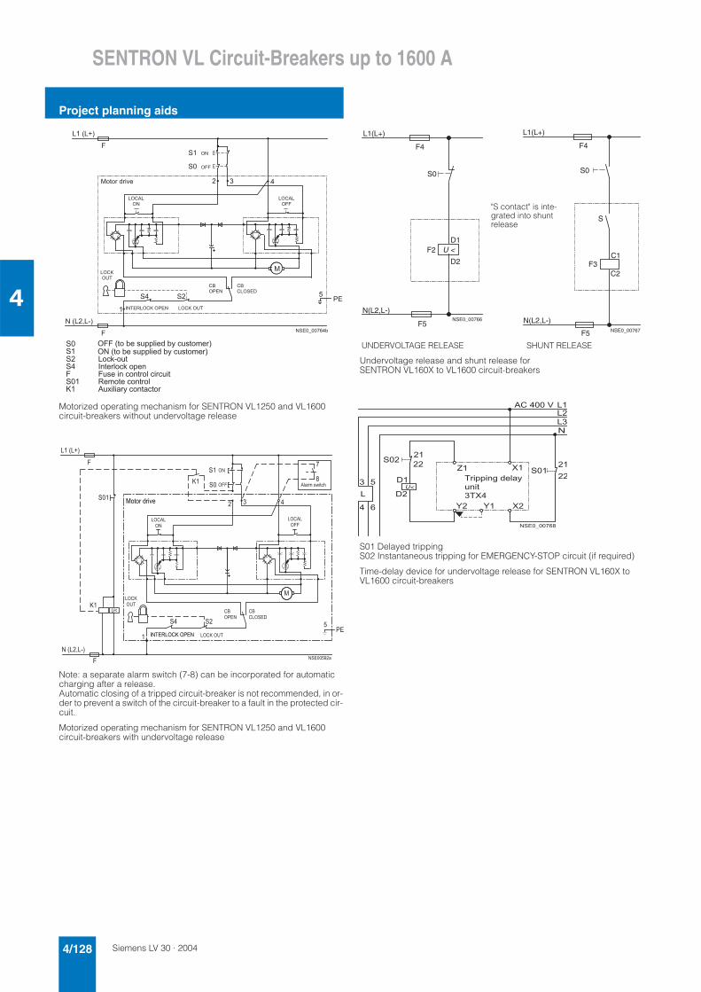
Siemens LV 30 · 20044/128
SENTRON VL Circuit-Breakers up to 1600 A
Project planning aids
4
Motorized operating mechanism for SENTRON VL1250 and VL1600 circuit-breakers without undervoltage release
Note: a separate alarm switch (7-8) can be incorporated for automatic charging after a release. Automatic closing of a tripped circuit-breaker is not recommended, in or-der to prevent a switch of the circuit-breaker to a fault in the protected cir-cuit.
Motorized operating mechanism for SENTRON VL1250 and VL1600 circuit-breakers with undervoltage release
Undervoltage release and shunt release for SENTRON VL160X to VL1600 circuit-breakers
S01 Delayed tripping S02 Instantaneous tripping for EMERGENCY-STOP circuit (if required)
Time-delay device for undervoltage release for SENTRON VL160X to VL1600 circuit-breakers
� �
� � � � < � � �
"
� � � � ( �
"
�
� �
�
� � � � � � � � � �
� �� � �
& +
! � � �
& +
& � ! � � �
� ! & $
! ? %
! " "
! �
� ! & ) �
! �
� ! & ) �
! " "
� - . - / � 6 / 4 B 1
# � % � � � ! & $ � ! � � � � ! & $ � ! ? %
� �
�
"
� �
$
! � � � . - � 1 � 5 8 = = 9 4 1 6 � 0 � * 8 5 . - � 1 / �
! " " � � . - � 1 � 5 8 = = 9 4 1 6 � 0 � * 8 5 . - � 1 / �
" 8 5 1 � 4 3 � * - 3 . / - 9 � * 4 / * 8 4 .
� 1 � - . 1 � * - 3 . / - 9
) 8 � 4 9 4 � / 0 � * - 3 . � * . - /
�
� �
� - * A � - 8 .
# 3 . 1 / 9 - * A � - = 1 3
����2���
3
�
����4�
3
�
� � �
�
�
� �
5�
5�
���
�
��
��� ����
��
�� ��
��6���
����6���
633
6�
�6���6�
�0�#%+1*"'(
�6���633
�6�5678
�!"!#,#*9&
:�8� �6�56��� �6�5678
N(L2,L-)
D2
F5
L1(L+)
D1F2
F4
S0
NSE0_00766
C2
F5
F4
S0
L1(L+)
S
F3C1
N(L2,L-)NSE0_00767
UNDERVOLTAGE RELEASE SHUNT RELEASE
"S contact" is inte-grated into shunt release
� �
�
�
�
�
�
�
�
� �
�
) & � � � � � �
� �
�
�
�
�
� �
� � � � � � � � � �
% / 4 = = 4 3 7 � 6 1 9 � 0 �
8 3 4 .
� % � �
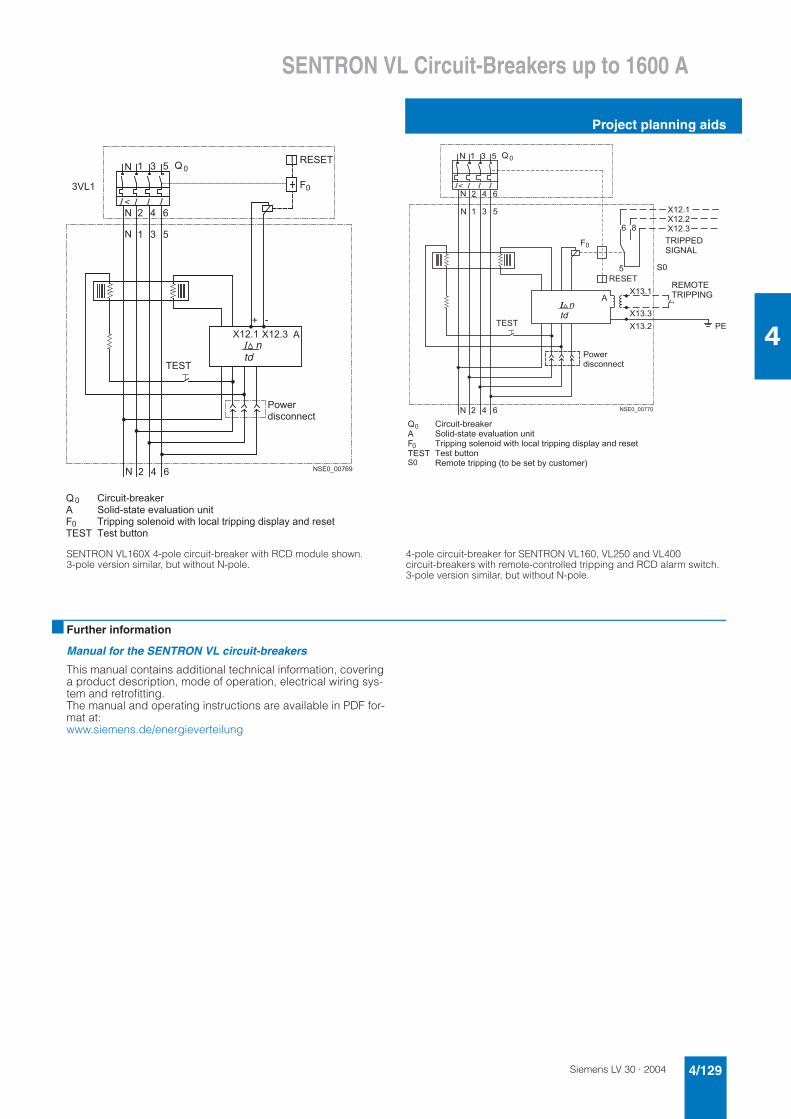
Siemens LV 30 · 2004 4/129
SENTRON VL Circuit-Breakers up to 1600 A
Project planning aids
4
SENTRON VL160X 4-pole circuit-breaker with RCD module shown. 3-pole version similar, but without N-pole.
4-pole circuit-breaker for SENTRON VL160, VL250 and VL400 circuit-breakers with remote-controlled tripping and RCD alarm switch. 3-pole version similar, but without N-pole.
■ Further information
Manual for the SENTRON VL circuit-breakers
This manual contains additional technical information, covering a product description, mode of operation, electrical wiring sys-tem and retrofitting. The manual and operating instructions are available in PDF for-mat at: www.siemens.de/energieverteilung
� � �
� � �� �
( �
�
�
�
�
�
�
�
#
� � � � � � � � � �
)
� � �
'�
� � � � %
"�
� - : 1 /
6 4 5 * - 3 3 1 * .
% � � %
& 4 / * 8 4 . � / 1 � A 1 /
� - 9 4 6 � 5 . � . 1 � 1 B � 9 8 � . 4 - 3 � 8 3 4 .
% / 4 = = 4 3 7 � 5 - 9 1 3 - 4 6 � : 4 . 2 � 9 - * � 9 � . / 4 = = 4 3 7 � 6 4 5 = 9 � 0 � � 3 6 � / 1 5 1 .
% 1 5 . � 8 . . - 3
'
)
"
% � � %
�
�
�� �
�
�
�
�
�
�
�
� � � �
� � �
#
� �
� � �
� �
� �
� �
� � �
� � � � � � � � � �
�
)
'�
� � � � %
"�
� - : 1 /
6 4 5 * - 3 3 1 * .
% � � %
� �
% � # � � � �
� # @ � ) �
� � � ! % �
% � # � � # � @
& 4 / * 8 4 . � / 1 � A 1 /
� - 9 4 6 � 5 . � . 1 � 1 B � 9 8 � . 4 - 3 � 8 3 4 .
% / 4 = = 4 3 7 � 5 - 9 1 3 - 4 6 � : 4 . 2 � 9 - * � 9 � . / 4 = = 4 3 7 � 6 4 5 = 9 � 0 � � 3 6 � / 1 5 1 .
% 1 5 . � 8 . . - 3
� 1 � - . 1 � . / 4 = = 4 3 7 � � . - � 1 � 5 1 . � 0 � * 8 5 . - � 1 / �
'
)
"
% � � %
� �
�
�
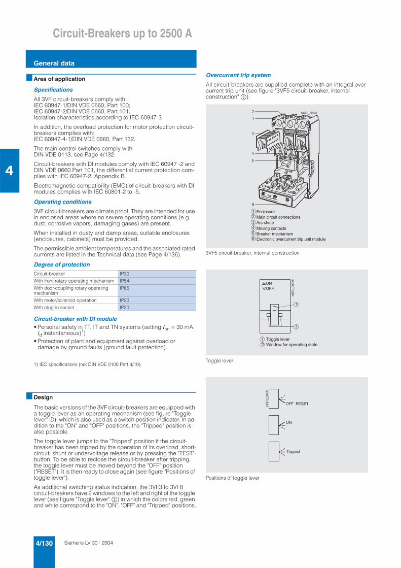
Siemens LV 30 · 20044/130
Circuit-Breakers up to 2500 A
General data
4
■ Area of application
Specifications
All 3VF circuit-breakers comply with: IEC 60947-1/DIN VDE 0660, Part 100; IEC 60947-2/DIN VDE 0660, Part 101. Isolation characteristics according to IEC 60947-3
In addition, the overload protection for motor protection circuit-breakers complies with: IEC 60947-4-1/DIN VDE 0660, Part 132.
The main control switches comply with DIN VDE 0113, see Page 4/132.
Circuit-breakers with DI modules comply with IEC 60947 -2 and DIN VDE 0660 Part 101, the differential current protection com-plies with IEC 60947-2, Appendix B.
Electromagnetic compatibility (EMC) of circuit-breakers with DI modules complies with IEC 60801-2 to -5.
Operating conditions
3VF circuit-breakers are climate proof. They are intended for use in enclosed areas where no severe operating conditions (e.g. dust, corrosive vapors, damaging gases) are present.
When installed in dusty and damp areas, suitable enclosures (enclosures, cabinets) must be provided.
The permissible ambient temperatures and the associated rated currents are listed in the Technical data (see Page 4/136).
Degree of protection
Circuit-breaker with DI module• Personal safety in TT, IT and TN systems (setting I∆n = 30 mA,
td instantaneous)1)• Protection of plant and equipment against overload or
damage by ground faults (ground fault protection).
1) IEC specifications (not DIN VDE 0100 Part 4/10).
■ Design
The basic versions of the 3VF circuit-breakers are equipped with a toggle lever as an operating mechanism (see figure "Toggle lever" ¿), which is also used as a switch position indicator. In ad-dition to the "ON" and "OFF" positions, the "Tripped" position is also possible.
The toggle lever jumps to the "Tripped" position if the circuit-breaker has been tripped by the operation of its overload, short-circuit, shunt or undervoltage release or by pressing the "TEST"-button. To be able to reclose the circuit-breaker after tripping, the toggle lever must be moved beyond the "OFF" position ("RESET"). It is then ready to close again (see figure "Positions of toggle lever").
As additional switching status indication, the 3VF3 to 3VF8 circuit-breakers have 2 windows to the left and right of the toggle lever (see figure "Toggle lever" %) in which the colors red, green and white correspond to the "ON", "OFF" and "Tripped" positions.
Overcurrent trip system
All circuit-breakers are supplied complete with an integral over-current trip unit (see figure "3VF5 circuit-breaker, internal construction" *).
3VF5 circuit-breaker, internal construction
Toggle lever
Positions of toggle lever
Circuit-breaker IP30
With front rotary operating mechanism IP54
With door-coupling rotary operating mechanism
IP65
With motor/solenoid operation IP20
With plug-in socket IP20
� � � � � � � � � �
�
�
�
�
� � � � � � � �
� � � � � � � � � � � � � � � � � � � �
� � � � � � �
� � � � � � � � � � � � �
� � � � � � � � � � � � � � � �
� � � � � � � � � � � � � � � � � � � � � � � � � � � � � � � ! � � �
�
�
�
�
" �
" # #
���������$
�
� � % � � � � � � � � � � �
� � � & � � ! � ' � ( � � � � � � � � � � � � � � � � �
���������
" # # � � ) � � � %
" �
% � � � !
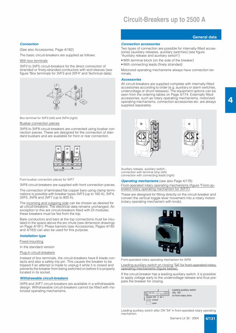
Siemens LV 30 · 2004 4/131
Circuit-Breakers up to 2500 A
General data
4
Connection
(See also Accessories, Page 4/182)
The basic circuit-breakers are supplied as follows:
With box terminals
3VF2 to 3VF5 circuit-breakers for the direct connection of stranded or finely-stranded conductors with end sleeves (see figure "Box terminals for 3VF3 and 3VF4" and Technical data).
Box terminal for 3VF3 (left) and 3VF4 (right)
Busbar connection pieces
3VF6 to 3VF8 circuit-breakers are connected using busbar con-nection pieces. These are designed for the connection of stan-dard busbars and are available for front or rear connection.
Front busbar connection pieces for 3VF7
3VF6 circuit-breakers are supplied with front connection pieces.
The connection of laminated flat copper bars using clamp termi-nations is possible with breaker types 3VF3 (up to 160 A), 3VF4, 3VF5, 3VF6 and 3VF7 (up to 800 A).
The incoming and outgoing side can be chosen as desired for all circuit-breakers. The electrical data remains unchanged. An exception to this are circuit-breakers fitted with DI modules: these breakers must be fed from the top.
Bare conductors and bars at the top connections must be insu-lated in the space above the arc chute (see dimension drawings on Page 4/191). Phase barriers (see Accessories, Pages 4/182 and 4/183) can also be used for this purpose.
Installation type
Fixed-mounting
In the standard version
Plug-in circuit-breakers
Instead of box terminals, the circuit-breakers have 6 blade con-tacts and also a safety trip pin. This causes the breaker to be tripped if an attempt is made to unplug it while it is closed and prevents the breaker from being switched on before it is properly located in its socket.
Withdrawable circuit-breakers
3VF6 and 3VF7 circuit-breakers are available in a withdrawable design. Withdrawable circuit-breakers cannot be fitted with mo-torized operating mechanisms.
Connection accessoriesTwo types of connection are possible for internally-fitted acces-sories (auxiliary releases, auxiliary switches) (see figure "Auxiliary release and auxiliary switch"):• With terminal block (on the side of the breaker)• With connecting leads (finely stranded)
Motorized operating mechanisms always have connection ter-minals.
AccessoriesAll circuit-breakers are supplied complete with internally-fitted accessories according to order (e.g. auxiliary or alarm switches, undervoltage or shunt releases). The equipment options can be seen from the ordering tables on Page 4/174. Externally fitted accessories, such as rotary operating mechanisms, motorized operating mechanisms, connection accessories etc. are always supplied separately.
Auxiliary release, auxiliary switch - connection with terminal strip (left) connection with connecting leads (right)
Operating mechanisms (see also Page 4/178)Front-operated rotary operating mechanisms (figure "Front-op-erated rotary operating mechanism for 3VF3")
These are designed for fitting directly on the circuit-breaker and convert the vertical toggle lever movement into a rotary motion (rotary operating mechanism with knob).
Front-operated rotary operating mechanism for 3VF6
Leading auxiliary switch on closing "S4" for front-operated rotary operating mechanisms (figure below).
If the circuit-breaker has a leading auxiliary switch, it is possible to apply voltage early to the undervoltage release and thus pre-pare the breaker for closing.
Leading auxiliary switch after ON "S4" in front-operated rotary operating mechanism
�����������
����������
����������
����������
�����������
�
�
�
* + � * � + � * �
� ' � � � � " �
� � � � !
� � �
* � � ! � � � � � � , � � � � � - � � ' � � �
" � + � . � .
� � � ( � � � � � � � � � � - � ! � � � �
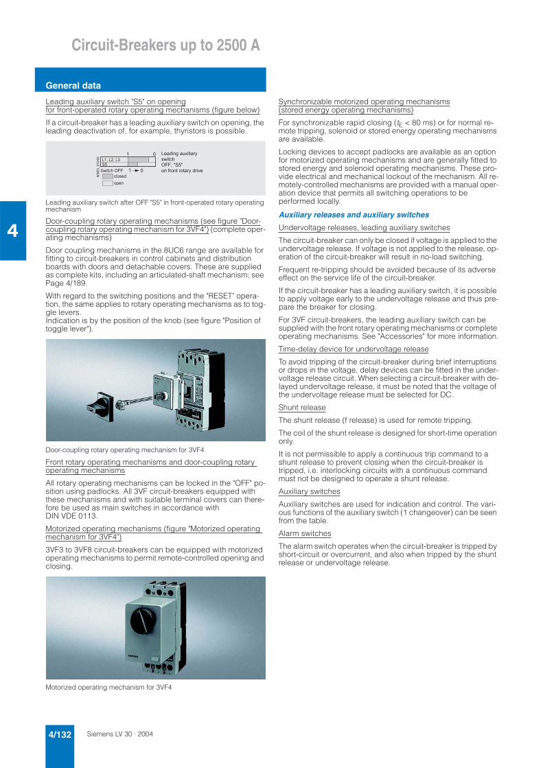
Siemens LV 30 · 20044/132
Circuit-Breakers up to 2500 A
General data
4
Leading auxiliary switch "S5" on openingfor front-operated rotary operating mechanisms (figure below)
If a circuit-breaker has a leading auxiliary switch on opening, the leading deactivation of, for example, thyristors is possible.
Leading auxiliary switch after OFF "S5" in front-operated rotary operating mechanism
Door-coupling rotary operating mechanisms (see figure "Door-coupling rotary operating mechanism for 3VF4") (complete oper-ating mechanisms)
Door coupling mechanisms in the 8UC6 range are available for fitting to circuit-breakers in control cabinets and distribution boards with doors and detachable covers. These are supplied as complete kits, including an articulated-shaft mechanism; see Page 4/189.
With regard to the switching positions and the "RESET" opera-tion, the same applies to rotary operating mechanisms as to tog-gle levers. Indication is by the position of the knob (see figure "Position of toggle lever").
Door-coupling rotary operating mechanism for 3VF4
Front rotary operating mechanisms and door-coupling rotary operating mechanisms
All rotary operating mechanisms can be locked in the "OFF" po-sition using padlocks. All 3VF circuit-breakers equipped with these mechanisms and with suitable terminal covers can there-fore be used as main switches in accordance withDIN VDE 0113.
Motorized operating mechanisms (figure "Motorized operating mechanism for 3VF4")
3VF3 to 3VF8 circuit-breakers can be equipped with motorized operating mechanisms to permit remote-controlled opening and closing.
Motorized operating mechanism for 3VF4
Synchronizable motorized operating mechanisms(stored energy operating mechanisms)
For synchronizable rapid closing (tE < 80 ms) or for normal re-mote tripping, solenoid or stored energy operating mechanisms are available.
Locking devices to accept padlocks are available as an option for motorized operating mechanisms and are generally fitted to stored energy and solenoid operating mechanisms. These pro-vide electrical and mechanical lockout of the mechanism. All re-motely-controlled mechanisms are provided with a manual oper-ation device that permits all switching operations to be performed locally.
Auxiliary releases and auxiliary switches
Undervoltage releases, leading auxiliary switches
The circuit-breaker can only be closed if voltage is applied to the undervoltage release. If voltage is not applied to the release, op-eration of the circuit-breaker will result in no-load switching.
Frequent re-tripping should be avoided because of its adverse effect on the service life of the circuit-breaker.
If the circuit-breaker has a leading auxiliary switch, it is possible to apply voltage early to the undervoltage release and thus pre-pare the breaker for closing.
For 3VF circuit-breakers, the leading auxiliary switch can be supplied with the front rotary operating mechanisms or complete operating mechanisms. See "Accessories" for more information.
Time-delay device for undervoltage release
To avoid tripping of the circuit-breaker during brief interruptions or drops in the voltage, delay devices can be fitted in the under-voltage release circuit. When selecting a circuit-breaker with de-layed undervoltage release, it must be noted that the voltage of the undervoltage release must be selected for DC.
Shunt release
The shunt release (f release) is used for remote tripping.
The coil of the shunt release is designed for short-time operation only.
It is not permissible to apply a continuous trip command to a shunt release to prevent closing when the circuit-breaker is tripped, i.e. interlocking circuits with a continuous command must not be designed to operate a shunt release.
Auxiliary switches
Auxiliary switches are used for indication and control. The vari-ous functions of the auxiliary switch (1 changeover) can be seen from the table.
Alarm switches
The alarm switch operates when the circuit-breaker is tripped by short-circuit or overcurrent, and also when tripped by the shunt release or undervoltage release.
��������
�
�
� �
* + � * � + � * �
� ' � � � � " # #
� � � � !
� � �
* � � ! � � � � � � , � � � � � - �
� ' � � �
" # # + � . � � .
� � � ( � � � � � � � � � � - � ! � � � �
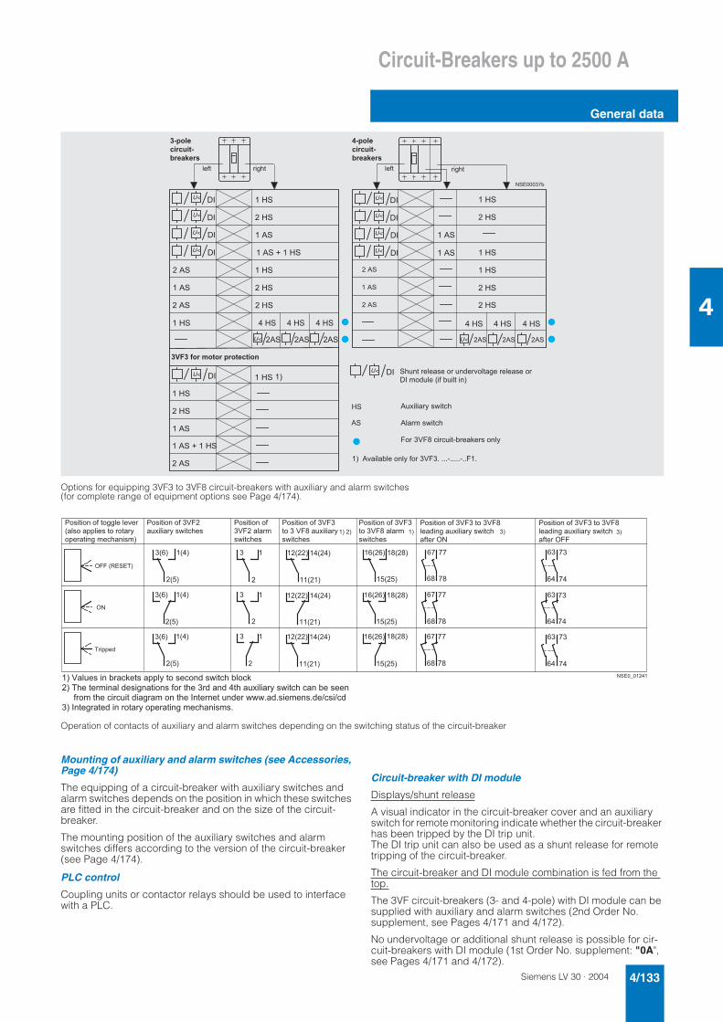
Siemens LV 30 · 2004 4/133
Circuit-Breakers up to 2500 A
General data
4
Options for equipping 3VF3 to 3VF8 circuit-breakers with auxiliary and alarm switches (for complete range of equipment options see Page 4/174).
Operation of contacts of auxiliary and alarm switches depending on the switching status of the circuit-breaker
Mounting of auxiliary and alarm switches (see Accessories, Page 4/174)
The equipping of a circuit-breaker with auxiliary switches and alarm switches depends on the position in which these switches are fitted in the circuit-breaker and on the size of the circuit-breaker.
The mounting position of the auxiliary switches and alarm switches differs according to the version of the circuit-breaker (see Page 4/174).
PLC control
Coupling units or contactor relays should be used to interface with a PLC.
Circuit-breaker with DI module
Displays/shunt release
A visual indicator in the circuit-breaker cover and an auxiliary switch for remote monitoring indicate whether the circuit-breaker has been tripped by the DI trip unit. The DI trip unit can also be used as a shunt release for remote tripping of the circuit-breaker.
The circuit-breaker and DI module combination is fed from the top.
The 3VF circuit-breakers (3- and 4-pole) with DI module can be supplied with auxiliary and alarm switches (2nd Order No. supplement, see Pages 4/171 and 4/172).
No undervoltage or additional shunt release is possible for cir-cuit-breakers with DI module (1st Order No. supplement: "0A",see Pages 4/171 and 4/172).
� � � �
� � �
� � � �
� � � �
� � �
� � � �
� / �
� � �
� � / �
� � � � 0 � � / �
� � � �
� / �
� � �
� � / �
� � � � 0 � � / �
� / �
� � / �
� � / �
� � �
� � �
� / �
� � / �
� � / �
� � / �
� / �
� / �
� � � � � � � 1 2
3 4
3 4
3 4
3 4
3 4
3 4
3 4
3 4
3 4
3 4
� � �
� / �
� � �
� / �
� � �
� / �
� � �
� / �
� � �
� / �
� � �
� / �
� / �
� / �
5
� � � � � �
� � � � � �
� � � � �
� � � � � �
� � � � � �
� � � � �
� � ( � � � � � � � � ( � � � � � �
� � � � � � � � � � � � � � � � � � � � � �
� � , � � � � � - � � ' � � �
� � � � � � � ' � � �
# � � � � 6 # 7 � � � � � � 8 2 � � � � � � � � � � � -
� � � � � � � � � � � � � � � � � � � ! � � � � � � � � � � � � � � � � � � � �
3 4 � � � ! � � � � 9 � ( � 2 � � � � � � � 5
/ �
� �
5 � � � � � � � � 2 � � � � � � - � ( � � � � 6 # � : � : : : 8 : : : : : 8 : : # :
� 9 � 5 9 5
� 9 � 5
� 9 � 5 9 5
� 9 � 5
� 9 � 5 9 5
� 9 � 5
� 9 � � 5 9 � 5
9 � 5
� 9 � � 5 9 � 5
9 � 5
� 9 � � 5 9 � 5
9 � 5
� 9 � � 5 7 9 � 7 5
� 9 � � 5
� 9 � � 5 7 9 � 7 5
� 9 � � 5
� 9 � � 5 7 9 � 7 5
� 9 � � 5
� 1 1 1
1 7� 7
� 1 1 1
1 7� 7
� 1 1 1
1 7� 7
�
�
�
�
�
�
� � � � � � �
� � 1 �
1 �
� � 1 �
1 �
� � 1 �
1 �
; � � � � � � � � � ( � � � � � � � � � � � � �
9 � � � � � � � � � � � � � � � � � � � -
� � � � � � � � � � � � � � � � � 5
" �
% � � � !
; � � � � � � � � � ( � � 6 # �
� � , � � � � � - � � ' � � � � �
; � � � � � � � � � ( �
� 6 # � � � � � � �
� ' � � � � �
; � � � � � � � � � ( � � 6 # � � � � � � 6 # 7 �
� � � ! � � � � � � , � � � � � - � � ' � � � �
� ( � � � � " �
" # # � 9 ) � � � % 5
� 5 �
; � � � � � � � � � ( � � 6 # � � � � � � 6 # 7 �
� � � ! � � � � � � , � � � � � - � � ' � � �
� ( � � � � " # #
� 5 �
5 � 6 � � � � � � � � � 2 � � � � � � � � � - � � � � � � � � ! � � ' � � � � 2 � � �
� 5 � % � � � � � � � � � � � � ! � � � � � � � � � � � � ( � � � � � � � � � ! � � � ! � � � � � � , � � � � � - � � ' � � � � � � � 2 � � � � � �
� � � � � ( � � � � � � � � � � � � � � ! � � � � � � � � � � � � � � 4 � � � � � � � � � � ! � � � ' ' ' : � ! : � � � � � � � : ! � < � � < !
� 5 � 4 � � � � � � � � ! � � � � � � � � � - � � � � � � � � � � � � � � � � � � � :
; � � � � � � � � � ( � � 6 # �
� � � � � 6 # 7 � � � , � � � � � -
� ' � � � � �
; � � � � � � � � � ( � � 6 # �
� � � � 6 # 7 � � � � � �
� ' � � � � �
5 � 5 � � 5
Siemens LV 30 · 20044/134
Circuit-Breakers up to 2500 A
General data
4
■ Functions
3VF2 to 3VF6 circuit-breakers for system protection with me-chanical overload and short-circuit release, i.e. overcurrent trip unit version "LI"
The overload and short-circuit releases function with bimetallic or magnetic elements. They can be supplied as non-adjustable or adjustable units.
Four-pole circuit-breakers for system protection can be supplied optionally with overcurrent trip units in all 4 poles or without over-current trip unit in the 4th pole (N). Above 100 A rated current the trip units in the 4th pole (N) are designed for 60 % of the current of the 3 main conductors to ensure safe protection for cables with reduced cross-section neutral conductors.
Electronic overcurrent trip unit for system protection (example 3VF7)
3VF5 to 3VF8 system protection circuit-breakers with electronic overcurrent trip unit
All 3VF7 to 3VF8 circuit-breakers are equipped with "LSI" elec-tronic overcurrent trip units for short-delay short-circuit tripping.
The electronic overcurrent trip unit system consists of: • 3 current transformers• Evaluation electronics with microprocessor• Tripping solenoid.
No auxiliary voltage supply is required for the release system.
A minimum load current of approximately 20% of the corre-sponding rated current In of the circuit-breaker is required to ac-tivate the overcurrent trip unit.
Fault-free operation of the overcurrent trip unit is indicated by the "heartbeat", a flashing LED ( ("ACTIVE") (see figure "Electronic overcurrent trip unit" (). A maintained light indicates an over-load condition I > 100 % In an.
Inverse-time delayed overload tripping operation "L"
The 3VF5 to 3VF8 circuit-breakers for system protection with electronic trip units have real r.m.s. current measuring and are therefore also suitable for use in networks with a high harmonic content. The harmonics are evaluated for overload protection in the usual manner.
The set current Ir can be set from 0.5 to 1 times the value of the rated current In of the circuit-breaker in 4 increments.
The time-lag class of the inverse-time delayed tripping operation corresponds to 10 s with 7.2 × Ir (see figure "Electronic overcur-rent trip unit" $).
Short-time delayed short-circuit tripping operation "S"
The operating value Id can be set in 7 increments between 2 and 8 times the value of Ir.
The delay time td can be set from 0 (instantaneous) to 300 ms in 4 increments.
This means that time-based discrimination to downstream cir-cuit-breakers can be achieved up to current values of
- 4.0 kA ± 15% for 3VF5,- 5.5 kA ± 15% for 3VF5,- 15 kA ± 15% for 3VF7 and- 20 kA ± 15% for 3VF8.
Instantaneous short-circuit tripping operation "I"
The operating value Ii of the instantaneous short-circuit release is set to a fixed value of 4 kA for 3VF5, 5.5 kA for 3VF6, 15 kA for 3VF7 and 20 kA for 3VF8. The electronic circuit of the overcurrent trip unit is inherently safe at high temperatures: if the tempera-ture of the printed circuit board rises to 90 °C the circuit-breaker trips.
Circuit-breakers for motor protection
All circuit-breakers for motor protection are equipped with elec-tronic overcurrent trip units. These work on the same principle as the electronic overcurrent trip units fitted to the line protection circuit-breakers.
The characteristic curve of the inverse-time delayed overcurrent trip unit is optimally matched to the overload behavior of three-phase motors. Depending on the version, the time lag character-istic of the overload release can be set in steps between "Class 5" and "Class 30".
Phase failure sensitivity is also integrated into this version vari-ant, so that the motor is provided with reliable protection even in the event of phase failure or severe asymmetry.
All 3VF3 to 3VF6 circuit-breakers for motor protection have a so-called "thermal memory" which stores the preload of the breaker and tripping history due to overload and takes account of the heating of the motor by reducing the tripping time. A cooling pe-riod of a few minutes may therefore be required following trip-ping due to overload before the motor can be re-started.
The same applies if there are too many starts within a short pe-riod which can cause the motor to heat up excessively. A reclos-ing lockout remains in force for one minute following a trip on overload.
In circuits with very high harmonic content caused by frequency converters or soft starters, 3VF2 to 3VF6 circuit-breakers with "LI" bimetal releases are recommended.
Circuit-breakers for starter combinations
Circuit-breakers for starter combinations are used in practice to-gether with a motor contactor and a matched overload relay.
Non-automatic circuit-breakers
Non-automatic circuit-breakers have integral short-circuit pro-tection so that back-up fuses are not required. 4-pole non-auto-matic circuit-breakers do not have a short-circuit release in the 4th pole (N).
Circuit-breakers as main control switches to EN 60204 or DIN VDE 0113 in combination with lockable rotary operating mechanisms with terminal covers or as EMERGENCY-STOP switches to EN 60204 or DIN VDE 0113 in combination with red operating mechanisms on yellow backgrounds and undervolt-age releases, if required.
� � � � �
7 � � � �
� � � � �
� � � � �
�
� � � �
! !
�
� �
� � � � �
� � � � � � � � � 7
� � �
� � �
� ��
� 7
1
�
�
� = % 4 6 �
� �
�
�
� � � 8 ! � � � - � !
� � � � � � � � � � � � � � � � � � � � � � � � � � � �
= � � � � � � � � � � � � � �
" � � � � � � � � � � � � � �
3 � � � - � � � � �
* � 3 � ( � � � � � � >
# � � � � 8 ( � � � � � � � � � � � � � � ( � � � � � � � � � � � � � � � � � � � � � � � � � � � � � ?
* � 3 � � � � � ! - � � � � � � >
" � � � � � � ! � � � � � �
�
!
!
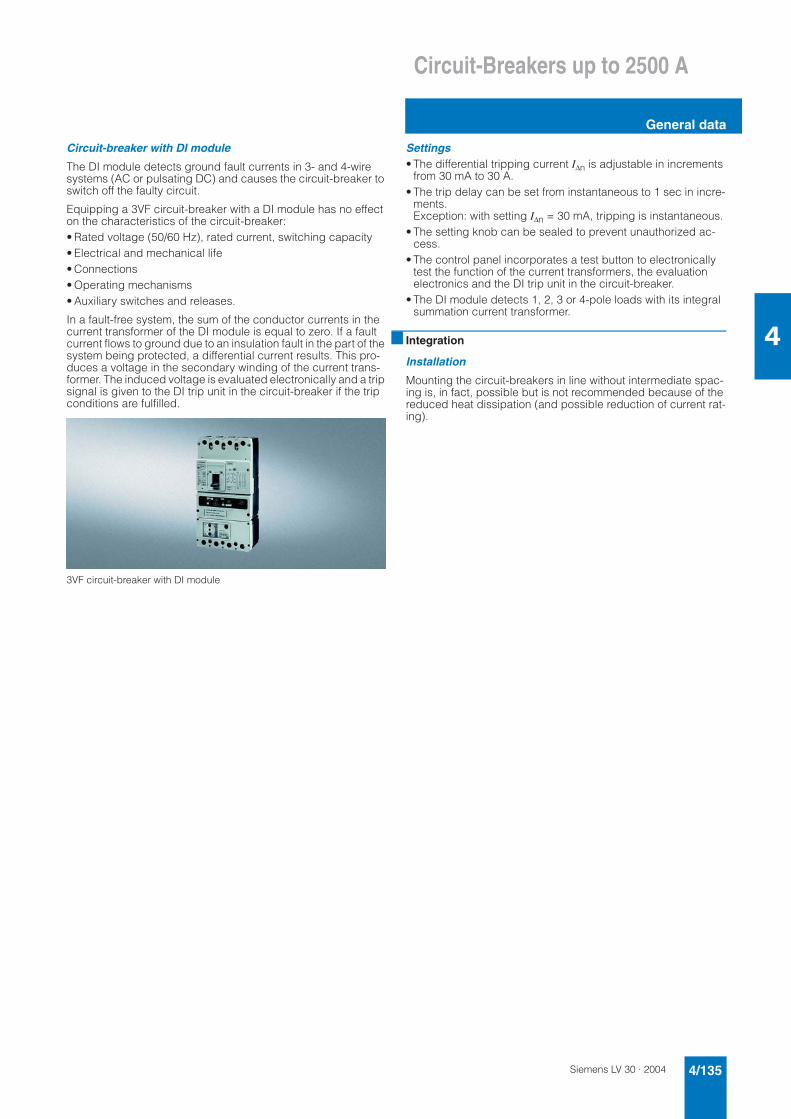
Siemens LV 30 · 2004 4/135
Circuit-Breakers up to 2500 A
General data
4
Circuit-breaker with DI module
The DI module detects ground fault currents in 3- and 4-wire systems (AC or pulsating DC) and causes the circuit-breaker to switch off the faulty circuit.
Equipping a 3VF circuit-breaker with a DI module has no effect on the characteristics of the circuit-breaker:• Rated voltage (50/60 Hz), rated current, switching capacity• Electrical and mechanical life• Connections• Operating mechanisms• Auxiliary switches and releases.
In a fault-free system, the sum of the conductor currents in the current transformer of the DI module is equal to zero. If a fault current flows to ground due to an insulation fault in the part of the system being protected, a differential current results. This pro-duces a voltage in the secondary winding of the current trans-former. The induced voltage is evaluated electronically and a trip signal is given to the DI trip unit in the circuit-breaker if the trip conditions are fulfilled.
3VF circuit-breaker with DI module
Settings• The differential tripping current I∆n is adjustable in increments
from 30 mA to 30 A.• The trip delay can be set from instantaneous to 1 sec in incre-
ments.Exception: with setting I∆n = 30 mA, tripping is instantaneous.
• The setting knob can be sealed to prevent unauthorized ac-cess.
• The control panel incorporates a test button to electronically test the function of the current transformers, the evaluation electronics and the DI trip unit in the circuit-breaker.
• The DI module detects 1, 2, 3 or 4-pole loads with its integral summation current transformer.
■ Integration
Installation
Mounting the circuit-breakers in line without intermediate spac-ing is, in fact, possible but is not recommended because of the reduced heat dissipation (and possible reduction of current rat-ing).
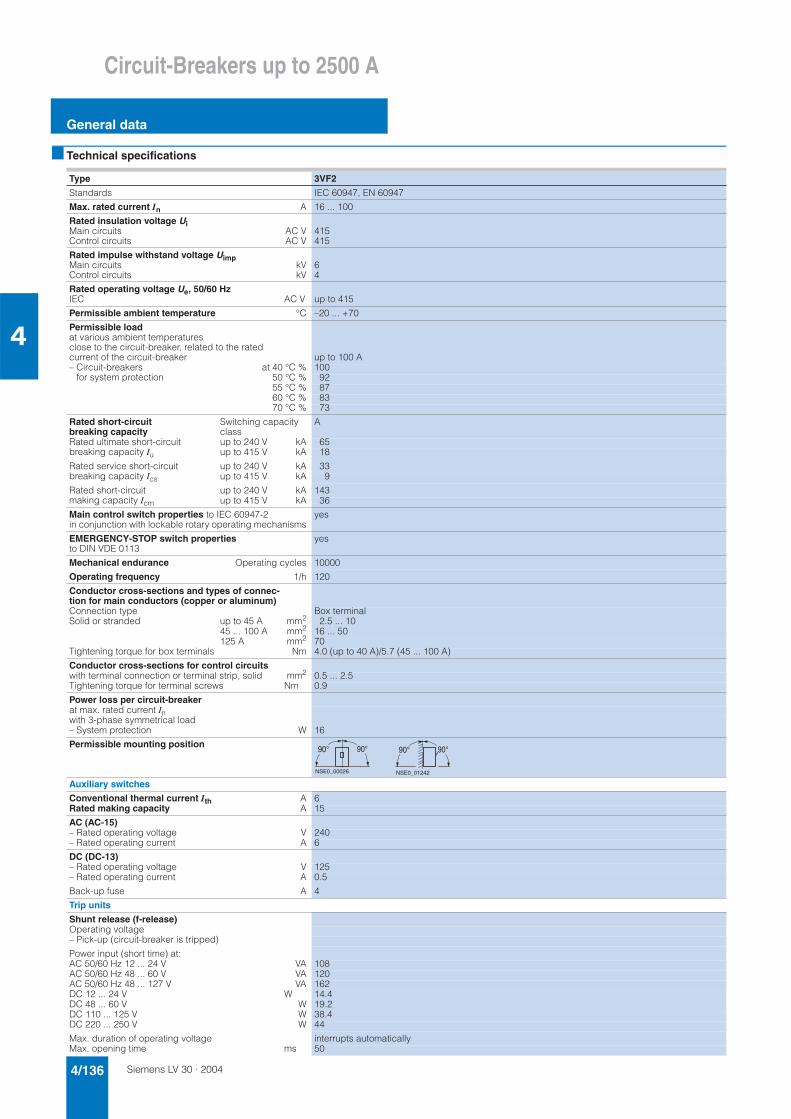
Siemens LV 30 · 20044/136
Circuit-Breakers up to 2500 A
General data
4
■ Technical specifications
Type 3VF2
Standards IEC 60947, EN 60947
Max. rated current In A 16 ... 100
Rated insulation voltage UiMain circuitsControl circuits
AC VAC V
415415
Rated impulse withstand voltage UimpMain circuitsControl circuits
kVkV
64
Rated operating voltage Ue, 50/60 HzIEC AC V up to 415
Permissible ambient temperature °C –20 ... +70
Permissible loadat various ambient temperatures close to the circuit-breaker, related to the rated current of the circuit-breaker up to 100 A– Circuit-breakers for system protection
at 40 °C % 10050 °C % 9255 °C % 8760 °C % 8370 °C % 73
Rated short-circuit breaking capacity
Switching capacity class
A
Rated ultimate short-circuit breaking capacity Iu
up to 240 V kA 65up to 415 V kA 18
Rated service short-circuit breaking capacity Ics
up to 240 V kA 33up to 415 V kA 9
Rated short-circuit making capacity Icm
up to 240 V kA 143up to 415 V kA 36
Main control switch properties to IEC 60947-2 in conjunction with lockable rotary operating mechanisms
yes
EMERGENCY-STOP switch propertiesto DIN VDE 0113
yes
Mechanical endurance Operating cycles 10000
Operating frequency 1/h 120
Conductor cross-sections and types of connec-tion for main conductors (copper or aluminum)Connection type Box terminalSolid or stranded up to 45 A mm2 2.5 ... 10
45 ... 100 A mm2 16 ... 50125 A mm2 70
Tightening torque for box terminals Nm 4.0 (up to 40 A)/5.7 (45 ... 100 A)
Conductor cross-sections for control circuitswith terminal connection or terminal strip, solid mm2 0.5 ... 2.5Tightening torque for terminal screws Nm 0.9
Power loss per circuit-breakerat max. rated current Inwith 3-phase symmetrical load– System protection W 16
Permissible mounting position
Auxiliary switches
Conventional thermal current Ith A 6Rated making capacity A 15
AC (AC-15)– Rated operating voltage V 240– Rated operating current A 6
DC (DC-13)– Rated operating voltage V 125– Rated operating current A 0.5
Back-up fuse A 4
Trip units
Shunt release (f-release)Operating voltage– Pick-up (circuit-breaker is tripped)
Power input (short time) at:AC 50/60 Hz 12 ... 24 V VA 108AC 50/60 Hz 48 ... 60 V VA 120AC 50/60 Hz 48 ... 127 V VA 162DC 12 ... 24 V W 14.4DC 48 ... 60 V W 19.2DC 110 ... 125 V W 38.4DC 220 ... 250 V W 44
Max. duration of operating voltage interrupts automaticallyMax. opening time ms 50
90° 90°
NSE0_00026
90° 90°
NSE0_01242
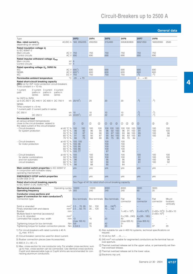
Siemens LV 30 · 2004 4/137
Circuit-Breakers up to 2500 A
General data
4
1) For circuit-breakers with rated currents ≤ 40 A: Ue max. 415 V.
2) Circuit-breaker cannot be used for direct current.
3) Busbar connection pieces (see Accessories).
4) 800 A: 3 × 40 × 5.
5) Max. cross-section for one conductor only. For smaller cross-sections: sum up to max. cross-section can be connected. Use identical cross-sections. CupAI end sleeves/cable lugs or CupAI shims are recommended for con-necting aluminum conductors.
6) Also suitable for use in 400 Hz systems, technical specifications on request.
7) 10 kA for 3VF.. ..–0....–....
8) 240 mm2 not suitable for segmented conductors as the terminal has an oval aperture.
$Thermal overload release set to the upper value, or permanently set ther-mal overload release.
%Thermal overload release set to the lower value.
&Electronic trip unit.
Type 3VF3 3VF4 3VF5 3VF6 3VF7 3VF8
Max. rated current In AC/DC A 160; 205/225 200/250 315/400 500/630/800 800/1250 1600/2000 2500depending on version
Rated insulation voltage Uito IEC 60947-2Main circuits AC V 750 750 750 750 750 750Control circuits AC V 690 690 690 690 690 690
Rated impulse withstand voltage UimpMain circuits kV 8Control circuits kV 4
Rated operating voltage Ue, 50/60 HzIEC AC V 6901) 690 690 690 690 690NEMA AC V 6001) 600 600 600 600 600IEC DC V 750 750 750 750 –2) –2)
Permissible ambient temperature °C –20 ... + 70 –5 ... + 60
Rated short-circuit breaking capacity (DC) not for 3VF motor protection circuit-breakersTime constant τ = 10 ms
1 current path
2 current paths in series
3 current paths in series
4 current paths in series
for 3VF3 to 3VF6up to DC 250 V DC 440 V DC 600 V DC 750 V kA 20/107) 20 20 20 –2) –2)
NEMATime constant τ = 8 ms1 current path 2 current paths in series
DC 250 V – kA 10 10 10 10 –2) –2)– DC 250 V kA 22/207) 22 22 22 –2) –2)
Permissible loadat various ambient temperatures close to the circuit-breaker, related to the rated current of the circuit-breaker
$ % $ % $ % & $ % & $ & &
– Circuit-breakers for system protection
at 40 °C %50 °C %55 °C %60 °C %70 °C %
10096939186
10092878373
10096949288
10094908780
10096939085
10092878475
10010010010085
10096939085
10091868270
100100100100
84
100918581
–
100100100100–
1001009692
–
– Circuit-breakers for motor protection
at 40 °C %50 °C %55 °C %60 °C %70 °C %
100; 100100; 96100; 90100; 86100; 77
–––––
100100100100
87
10010010010090
–––––
–––––
– Circuit-breakers for starter combinations and non-automatic circuit-breakers
at 40 °C %50 °C %55 °C %60 °C %70 °C %
100100
969186
100100969288
100100
959085
100100959084
100918581
–
100100100100–
1001009692
–
Main control switch properties to IEC 60947-2 in conjunction with lockable rotary operating mechanisms
yes yes yes yes yes yes
EMERGENCY-STOP switch properties to DIN VDE 0113
yes yes yes yes yes yes
Rated short-circuit breaking capacityto IEC 60947-2 (AC 50/60 Hz)6)
See Page 4/141 for rated short-circuit breaking capacity.
Mechanical enduranceOperating frequency
Operating cycles1/h
10000300
10000240
8000240
8000240
300060
300020
Conductor cross-sections and types of connection for main conductors5)Connection type Box terminals Box terminals Box terminals Flat
connectorFlatconnector
Flatconnector
Mountbusbarsvertically
Solid or stranded mm2 2.5 ... 70; 95 50 ... 150 95 ... 2408) – – – –Finely stranded with end sleeve mm2 2.5 ... 50; 70 35 ... 120 70 ... 150 – – – –Busbar mm – – – 1×40 × 104) 2×40×103) 2×60×103)/ 3×80×10Multiple feed-in terminal (accessory) 2×80×103)Cu or Al, stranded mm2 – – – 2×(185...240) 4×(95...185) – –Laminated flat copper, max. width mm 13
(max 160 A)15 20 40
(max 630 A)40(max 800 A)
– –
Tightening torque for box terminals Nm 5/9 20 42 31 31 – –Tightening torque for busbar connection pieces Nm 4.5/4.5 15 30 6 50 37 20
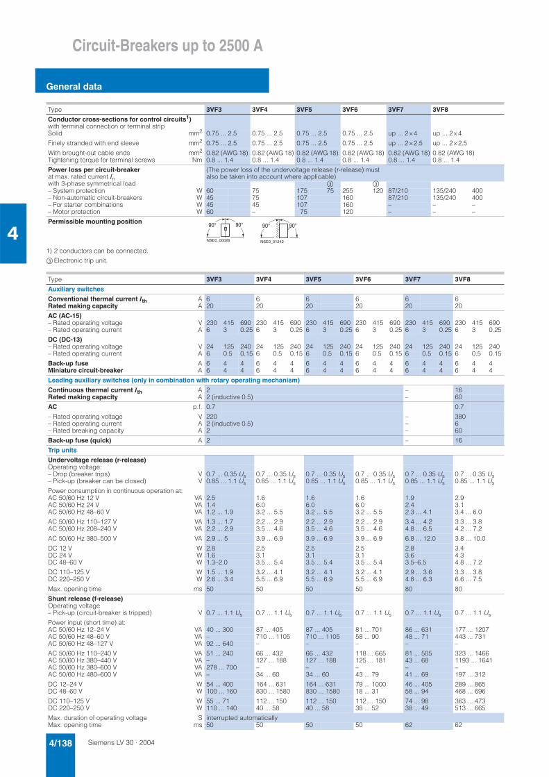
Siemens LV 30 · 20044/138
Circuit-Breakers up to 2500 A
General data
41) 2 conductors can be connected.
&Electronic trip unit.
Type 3VF3 3VF4 3VF5 3VF6 3VF7 3VF8
Conductor cross-sections for control circuits1)with terminal connection or terminal stripSolid mm2 0.75 ... 2.5 0.75 ... 2.5 0.75 ... 2.5 0.75 ... 2.5 up ... 2×4 up ... 2×4
Finely stranded with end sleeve mm2 0.75 ... 2.5 0.75 ... 2.5 0.75 ... 2.5 0.75 ... 2.5 up ... 2×2.5 up ... 2×2.5
With brought-out cable ends mm2 0.82 (AWG 18) 0.82 (AWG 18) 0.82 (AWG 18) 0.82 (AWG 18) 0.82 (AWG 18) 0.82 (AWG 18)Tightening torque for terminal screws Nm 0.8 ... 1.4 0.8 ... 1.4 0.8 ... 1.4 0.8 ... 1.4 0.8 ... 1.4 0.8 ... 1.4
Power loss per circuit-breakerat max. rated current Inwith 3-phase symmetrical load
(The power loss of the undervoltage release (r-release) must also be taken into account where applicable)
& &– System protection W 60 75 175 75 255 120 87/210 135/240 400– Non-automatic circuit-breakers W 45 75 107 160 87/210 135/240 400– For starter combinations W 45 45 107 160 – – –– Motor protection W 60 – 75 120 – – –
Permissible mounting position 90° 90°
NSE0_00026
90° 90°
NSE0_01242
Type 3VF3 3VF4 3VF5 3VF6 3VF7 3VF8
Auxiliary switches
Conventional thermal current Ith A 6 6 6 6 6 6Rated making capacity A 20 20 20 20 20 20
AC (AC-15)– Rated operating voltage V 230 415 690 230 415 690 230 415 690 230 415 690 230 415 690 230 415 690– Rated operating current A 6 3 0.25 6 3 0.25 6 3 0.25 6 3 0.25 6 3 0.25 6 3 0.25
DC (DC-13)– Rated operating voltage V 24 125 240 24 125 240 24 125 240 24 125 240 24 125 240 24 125 240– Rated operating current A 6 0.5 0.15 6 0.5 0.15 6 0.5 0.15 6 0.5 0.15 6 0.5 0.15 6 0.5 0.15
Back-up fuse A 6 4 4 6 4 4 6 4 4 6 4 4 6 4 4 6 4 4Miniature circuit-breaker A 6 4 4 6 4 4 6 4 4 6 4 4 6 4 4 6 4 4
Leading auxiliary switches (only in combination with rotary operating mechanism)
Continuous thermal current Ith A 2 – 16Rated making capacity A 2 (inductive 0.5) – 60
AC p.f. 0.7 0.7
– Rated operating voltage V 220 – 380– Rated operating current A 2 (inductive 0.5) – 6– Rated breaking capacity A 2 – 60
Back-up fuse (quick) A 2 – 16
Trip units
Undervoltage release (r-release)Operating voltage:– Drop (breaker trips) V 0.7 ... 0.35 Us 0.7 ... 0.35 Us 0.7 ... 0.35 Us 0.7 ... 0.35 Us 0.7 ... 0.35 Us 0.7 ... 0.35 Us– Pick-up (breaker can be closed) V 0.85 ... 1.1 Us 0.85 ... 1.1 Us 0.85 ... 1.1 Us 0.85 ... 1.1 Us 0.85 ... 1.1 Us 0.85 ... 1.1 Us
Power consumption in continuous operation at:AC 50/60 Hz 12 V VA 2.5 1.6 1.6 1.6 1.9 2.9AC 50/60 Hz 24 V VA 1.4 6.0 6.0 6.0 2.4 3.1AC 50/60 Hz 48–60 V VA 1.2 ... 1.9 3.2 ... 5.5 3.2 ... 5.5 3.2 ... 5.5 2.3 ... 4.1 3.4 ... 6.0
AC 50/60 Hz 110–127 V VA 1.3 ... 1.7 2.2 ... 2.9 2.2 ... 2.9 2.2 ... 2.9 3.4 ... 4.2 3.3 ... 3.8AC 50/60 Hz 208–240 V VA 2.2 ... 2.9 3.5 ... 4.6 3.5 ... 4.6 3.5 ... 4.6 4.8 ... 6.5 4.2 ... 7.2
AC 50/60 Hz 380–500 V VA 2.9 ... 5 3.9 ... 6.9 3.9 ... 6.9 3.9 ... 6.9 6.8 ... 12.0 3.8 ... 10.0
DC 12 V W 2.8 2.5 2.5 2.5 2.8 3.4DC 24 V W 1.6 3.1 3.1 3.1 3.6 4.3DC 48–60 V W 1.3–2.0 3.5 ... 5.4 3.5 ... 5.4 3.5 ... 5.4 3.5–6.5 4.8 ... 7.2
DC 110–125 V W 1.5 ... 1.9 3.2 ... 4.1 3.2 ... 4.1 3.2 ... 4.1 2.9 ... 3.6 3.3 ... 3.8DC 220–250 V W 2.6 ... 3.4 5.5 ... 6.9 5.5 ... 6.9 5.5 ... 6.9 4.8 ... 6.3 6.6 ... 7.5
Max. opening time ms 50 50 50 50 80 80
Shunt release (f-release)Operating voltage– Pick-up (circuit-breaker is tripped) V 0.7 ... 1.1 Us 0.7 ... 1.1 Us 0.7 ... 1.1 Us 0.7 ... 1.1 Us 0.7 ... 1.1 Us 0.7 ... 1.1 Us
Power input (short time) at:AC 50/60 Hz 12–24 V VA 40 ... 300 87 ... 405 87 ... 405 81 ... 701 86 ... 631 177 ... 1207AC 50/60 Hz 48–60 V VA – 710 ... 1105 710 ... 1105 58 ... 90 48 ... 71 443 ... 731AC 50/60 Hz 48–127 V VA 92 ... 640 – – – – –
AC 50/60 Hz 110–240 V VA 51 ... 240 66 ... 432 66 ... 432 118 ... 665 81 ... 505 323 ... 1466AC 50/60 Hz 380–440 V VA – 127 ... 188 127 ... 188 125 ... 181 43 ... 68 1193 ... 1641AC 50/60 Hz 380–600 V VA 278 ... 700 – – – – –AC 50/60 Hz 480–600 V VA – 34 ... 60 34 ... 60 43 ... 79 41 ... 69 197 ... 312
DC 12–24 V W 54 ... 400 164 ... 631 164 ... 631 79 ... 1000 46 ... 405 289 ... 865DC 48–60 V W 100 ... 160 830 ... 1580 830 ... 1580 18 ... 31 58 ... 94 468 ... 696
DC 110–125 V W 55 ... 71 112 ... 150 112 ... 150 112 ... 150 74 ... 98 363 ... 473DC 220–250 V W 110 ... 140 40 ... 58 40 ... 58 38 ... 52 38 ... 49 513 ... 665
Max. duration of operating voltage S interrupted automaticallyMax. opening time ms 50 50 50 50 62 62
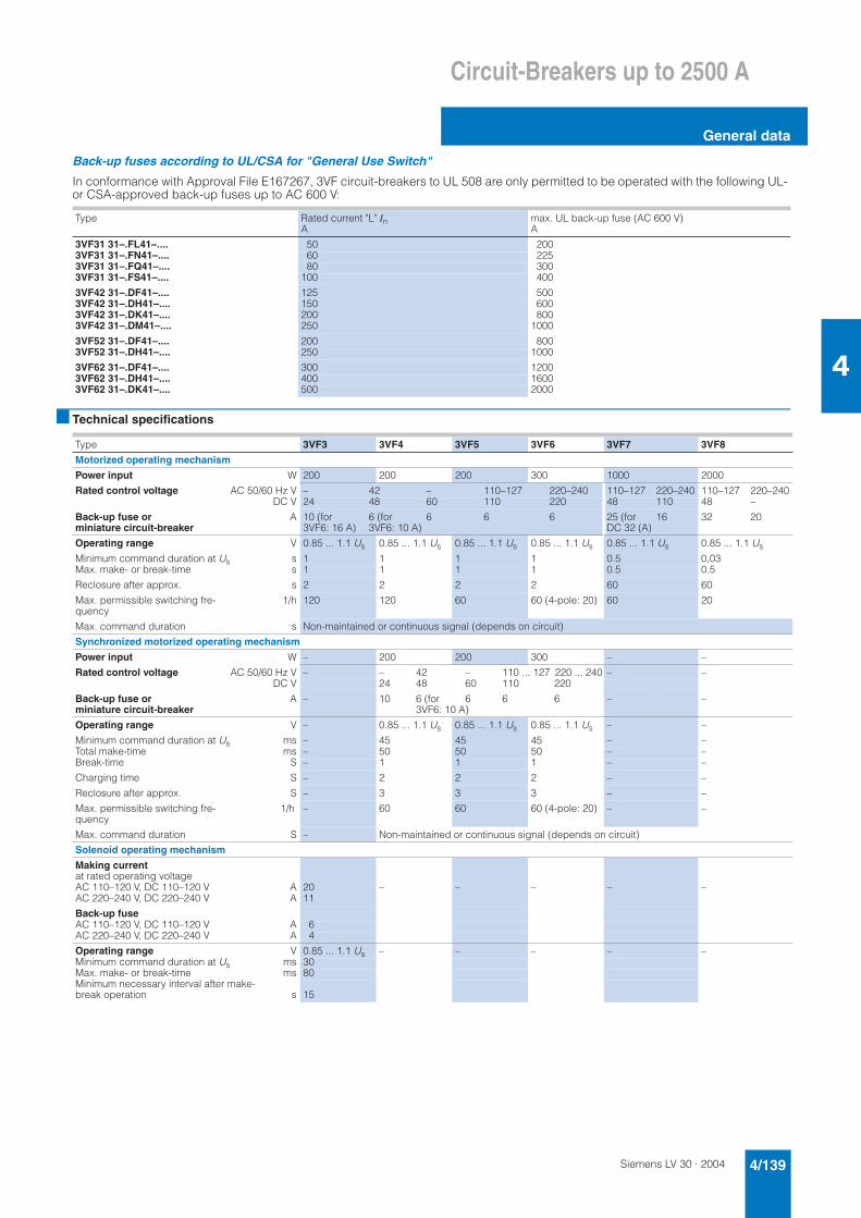
Siemens LV 30 · 2004 4/139
Circuit-Breakers up to 2500 A
General data
4
Back-up fuses according to UL/CSA for "General Use Switch"
In conformance with Approval File E167267, 3VF circuit-breakers to UL 508 are only permitted to be operated with the following UL-or CSA-approved back-up fuses up to AC 600 V:
■ Technical specifications
Type Rated current "L" InA
max. UL back-up fuse (AC 600 V)A
3VF31 31–.FL41–.... 50 2003VF31 31–.FN41–.... 60 2253VF31 31–.FQ41–.... 80 3003VF31 31–.FS41–.... 100 400
3VF42 31–.DF41–.... 125 5003VF42 31–.DH41–.... 150 6003VF42 31–.DK41–.... 200 8003VF42 31–.DM41–.... 250 1000
3VF52 31–.DF41–.... 200 8003VF52 31–.DH41–.... 250 1000
3VF62 31–.DF41–.... 300 12003VF62 31–.DH41–.... 400 16003VF62 31–.DK41–.... 500 2000
Type 3VF3 3VF4 3VF5 3VF6 3VF7 3VF8
Motorized operating mechanism
Power input W 200 200 200 300 1000 2000
Rated control voltage AC 50/60 Hz V – 42 – 110–127 220–240 110–127 220–240 110–127 220–240DC V 24 48 60 110 220 48 110 48 –
Back-up fuse or miniature circuit-breaker
A 10 (for 6 (for 6 6 63VF6: 16 A) 3VF6: 10 A)
25 (for DC 32 (A)
16 32 20
Operating range V 0.85 ... 1.1 Us 0.85 ... 1.1 Us 0.85 ... 1.1 Us 0.85 ... 1.1 Us 0.85 ... 1.1 Us 0.85 ... 1.1 Us
Minimum command duration at Us s 1 1 1 1 0.5 0,03Max. make- or break-time s 1 1 1 1 0.5 0.5
Reclosure after approx. s 2 2 2 2 60 60
Max. permissible switching fre-quency
1/h 120 120 60 60 (4-pole: 20) 60 20
Max. command duration s Non-maintained or continuous signal (depends on circuit)
Synchronized motorized operating mechanism
Power input W – 200 200 300 – –
Rated control voltage AC 50/60 Hz V – – 42 – 110 ... 127 220 ... 240 – –DC V 24 48 60 110 220
Back-up fuse or miniature circuit-breaker
A – 10 6 (for 6 6 63VF6: 10 A)
– –
Operating range V – 0.85 ... 1.1 Us 0.85 ... 1.1 Us 0.85 ... 1.1 Us – –
Minimum command duration at Us ms – 45 45 45 – –Total make-time ms – 50 50 50 – –Break-time S – 1 1 1 – –
Charging time S – 2 2 2 – –
Reclosure after approx. S – 3 3 3 – –
Max. permissible switching fre-quency
1/h – 60 60 60 (4-pole: 20) – –
Max. command duration S – Non-maintained or continuous signal (depends on circuit)
Solenoid operating mechanism
Making currentat rated operating voltageAC 110–120 V, DC 110–120 V A 20 – – – – –AC 220–240 V, DC 220–240 V A 11
Back-up fuseAC 110–120 V, DC 110–120 V A 6AC 220–240 V, DC 220–240 V A 4
Operating range V 0.85 ... 1.1 Us – – – – –Minimum command duration at Us ms 30Max. make- or break-time ms 80Minimum necessary interval after make-break operation s 15
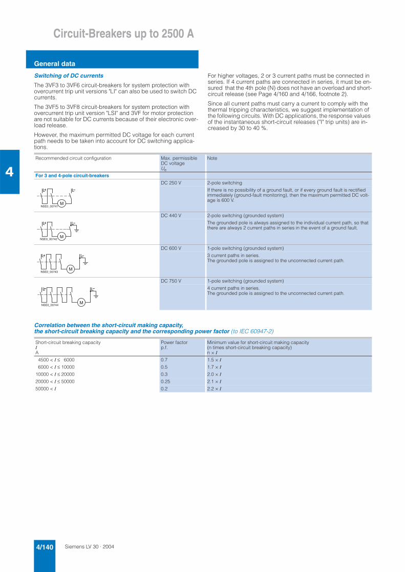
Siemens LV 30 · 20044/140
Circuit-Breakers up to 2500 A
General data
4
Switching of DC currents
The 3VF3 to 3VF6 circuit-breakers for system protection with overcurrent trip unit versions "LI" can also be used to switch DC currents.
The 3VF5 to 3VF8 circuit-breakers for system protection with overcurrent trip unit version "LSI" and 3VF for motor protection are not suitable for DC currents because of their electronic over-load release.
However, the maximum permitted DC voltage for each current path needs to be taken into account for DC switching applica-tions.
For higher voltages, 2 or 3 current paths must be connected in series. If 4 current paths are connected in series, it must be en-sured that the 4th pole (N) does not have an overload and short-circuit release (see Page 4/160 and 4/166, footnote 2).
Since all current paths must carry a current to comply with the thermal tripping characteristics, we suggest implementation of the following circuits. With DC applications, the response values of the instantaneous short-circuit releases ("I" trip units) are in-creased by 30 to 40 %.
Correlation between the short-circuit making capacity, the short-circuit breaking capacity and the corresponding power factor (to IEC 60947-2)
Recommended circuit configuration Max. permissible DC voltage Ue
Note
For 3 and 4-pole circuit-breakers
DC 250 V 2-pole switching
If there is no possibility of a ground fault, or if every ground fault is rectified immediately (ground-fault monitoring), then the maximum permitted DC volt-age is 600 V.
DC 440 V 2-pole switching (grounded system)
The grounded pole is always assigned to the individual current path, so that there are always 2 current paths in series in the event of a ground fault.
DC 600 V 1-pole switching (grounded system)
3 current paths in series. The grounded pole is assigned to the unconnected current path.
DC 750 V 1-pole switching (grounded system)
4 current paths in series. The grounded pole is assigned to the unconnected current path.
L
NSE0_00741M
L
L
NSE0_00742M
L
L
NSE0_00743M
L
L L
NSE0_00744M
Short-circuit breaking capacityIA
Power factorp.f.
Minimum value for short-circuit making capacity (n times short-circuit breaking capacity) n × I
4500 < I ≤ 6000 0.7 1.5 × I
6000 < I ≤ 10000 0.5 1.7 × I
10000 < I ≤ 20000 0.3 2.0 × I
20000 < I ≤ 50000 0.25 2.1 × I
50000 < I 0.2 2.2 × I
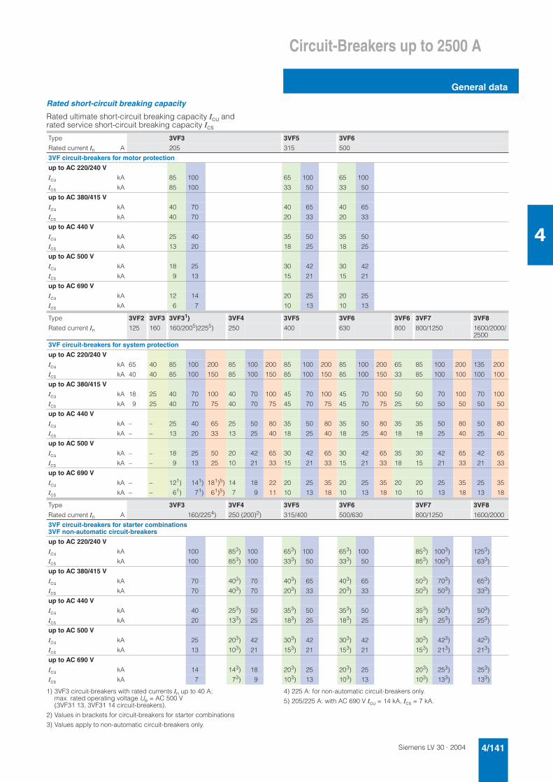
Siemens LV 30 · 2004 4/141
Circuit-Breakers up to 2500 A
General data
4
Rated short-circuit breaking capacity
Rated ultimate short-circuit breaking capacity Icu and rated service short-circuit breaking capacity Ics
1) 3VF3 circuit-breakers with rated currents In up to 40 A; max. rated operating voltage Ue = AC 500 V (3VF31 13, 3VF31 14 circuit-breakers).
2) Values in brackets for circuit-breakers for starter combinations
3) Values apply to non-automatic circuit-breakers only.
4) 225 A: for non-automatic circuit-breakers only.
5) 205/225 A: with AC 690 V Icu = 14 kA, Ics = 7 kA.
Type 3VF3 3VF5 3VF6
Rated current In A 205 315 500
3VF circuit-breakers for motor protection
up to AC 220/240 V
Icu kA 85 100 65 100 65 100
Ics kA 85 100 33 50 33 50
up to AC 380/415 V
Icu kA 40 70 40 65 40 65
Ics kA 40 70 20 33 20 33
up to AC 440 V
Icu kA 25 40 35 50 35 50
Ics kA 13 20 18 25 18 25
up to AC 500 V
Icu kA 18 25 30 42 30 42
Ics kA 9 13 15 21 15 21
up to AC 690 V
Icu kA 12 14 20 25 20 25
Ics kA 6 7 10 13 10 13
Type 3VF2 3VF3 3VF31) 3VF4 3VF5 3VF6 3VF6 3VF7 3VF8
Rated current In 125 160 160/2005)2255) 250 400 630 800 800/1250 1600/2000/2500
3VF circuit-breakers for system protection
up to AC 220/240 V
Icu kA 65 40 85 100 200 85 100 200 85 100 200 85 100 200 65 85 100 200 135 200
Ics kA 40 40 85 100 150 85 100 150 85 100 150 85 100 150 33 85 100 100 100 100
up to AC 380/415 V
Icu kA 18 25 40 70 100 40 70 100 45 70 100 45 70 100 50 50 70 100 70 100
Ics kA 9 25 40 70 75 40 70 75 45 70 75 45 70 75 25 50 50 50 50 50
up to AC 440 V
Icu kA – – 25 40 65 25 50 80 35 50 80 35 50 80 35 35 50 80 50 80
Ics kA – – 13 20 33 13 25 40 18 25 40 18 25 40 18 18 25 40 25 40
up to AC 500 V
Icu kA – – 18 25 50 20 42 65 30 42 65 30 42 65 35 30 42 65 42 65
Ics kA – – 9 13 25 10 21 33 15 21 33 15 21 33 18 15 21 33 21 33
up to AC 690 V
Icu kA – – 121) 141) 181)5) 14 18 22 20 25 35 20 25 35 20 20 25 35 25 35
Ics kA – – 61) 71) 61)5) 7 9 11 10 13 18 10 13 18 10 10 13 18 13 18
Type 3VF3 3VF4 3VF5 3VF6 3VF7 3VF8
Rated current In A 160/2254) 250 (200)2) 315/400 500/630 800/1250 1600/2000
3VF circuit-breakers for starter combinations3VF non-automatic circuit-breakers
up to AC 220/240 V
Icu kA 100 853) 100 653) 100 653) 100 853) 1003) 1253)
Ics kA 100 853) 100 333) 50 333) 50 853) 1003) 633)
up to AC 380/415 V
Icu kA 70 403) 70 403) 65 403) 65 503) 703) 653)
Ics kA 70 403) 70 203) 33 203) 33 503) 503) 333)
up to AC 440 V
Icu kA 40 253) 50 353) 50 353) 50 353) 503) 503)
Ics kA 20 133) 25 183) 25 183) 25 183) 253) 253)
up to AC 500 V
Icu kA 25 203) 42 303) 42 303) 42 303) 423) 423)
Ics kA 13 103) 21 153) 21 153) 21 153) 213) 213)
up to AC 690 V
Icu kA 14 143) 18 203) 25 203) 25 203) 253) 253)
Ics kA 7 73) 9 103) 13 103) 13 103) 133) 133)

Siemens LV 30 · 20044/142
Circuit-Breakers up to 2500 A
3-pole, fixed-mounted design
4
■ Selection and ordering data
Pack size for 3VF is one unit, i.e. one unit or a multiple thereof can be ordered.
For shunt releases and auxiliary/alarm switches see Accessories, Page 4/173.
System protection, TM3VF2 circuit-breakers, up to 18 kAMaking/breaking capacity class A
Rated ultimate short-circuitbreaking capacity Icu
up to 240 Vup to 415 V
kAkA
6518
Rated service short-circuit breaking capacity Ics
up to 240 Vup to 415 V
kAkA
339
Rated short-circuit making capacity Icm
up to 240 Vup to 415 V
kAkA
14338
Rated current In
Setting current of the inverse-time delayed overload release "L"
Ir
Operating current of instantaneousshort-circuit release "I"
Ii
DT VF100 circuit-breakerMaking/breaking capacity class A
Weight per PU approx.
A A A Order No. kg
With permanently set thermal overload releases
16 16 350 B 3VF22 13–0FC41–0AA0 0.94820 20 450 B 3VF22 13–0FD41–0AA0 0.95325 25 500 B 3VF22 13–0FE41–0AA0 0.96132 32 600 B 3VF22 13–0FG41–0AA0 0.949
40 40 750 B 3VF22 13–0FJ41–0AA0 0.97345 45 750 B 3VF22 13–0FK41–0AA0 0.96050 50 800 B 3VF22 13–0FL41–0AA0 0.963
63 63 800 B 3VF22 13–0FN41–0AA0 0.96770 70 900 B 3VF22 13–0FP41–0AA0 0.98080 80 900 B 3VF22 13–0FQ41–0AA0 0.97690 90 1000 B 3VF22 13–0FR41–0AA0 0.968
100 100 1000 B 3VF22 13–0FS41–0AA0 0.977
NSE0_00695
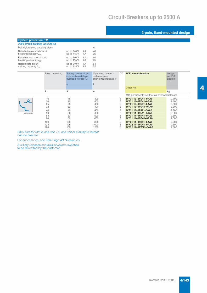
Siemens LV 30 · 2004 4/143
Circuit-Breakers up to 2500 A
3-pole, fixed-mounted design
4
Pack size for 3VF is one unit, i.e. one unit or a multiple thereof can be ordered.
For accessories, see from Page 4/174 onwards.
Auxiliary releases and auxiliary/alarm switches to be retrofitted by the customer.
System protection, TM3VF3 circuit-breaker, up to 25 kAMaking/breaking capacity class A
Rated ultimate short-circuitbreaking capacity Icu
up to 240 Vup to 415 V
kAkA
4025
Rated service short-circuit breaking capacity Ics
up to 240 Vup to 415 V
kAkA
4025
Rated short-circuit making capacity Icm
up to 240 Vup to 415 V
kAkA
8452
Rated current In Setting current of the inverse-time delayed overload release "L"
Ir
Operating current of instantaneousshort-circuit release "I"
Ii
DT 3VF3 circuit-breaker Weight per PU approx.
Order No.
A A A kg
With permanently set thermal overload releases
16 16 400 B 3VF31 13–0FC41–0AA0 2.30020 20 400 B 3VF31 13–0FD41–0AA0 2.30025 25 400 B 3VF31 13–0FE41–0AA0 2.30032 32 400 B 3VF31 13–0FG41–0AA0 2.300
40 40 400 B 3VF31 13–0FJ41–0AA0 2.30050 50 400 B 3VF31 11–0FL41–0AA0 2.30063 63 500 B 3VF31 11–0FN41–0AA0 2.30080 80 630 B 3VF31 11–0FQ41–0AA0 2.300
100 100 800 B 3VF31 11–0FS41–0AA0 2.300125 125 1000 B 3VF32 11–0FU41–0AA0 2.300160 160 1280 B 3VF32 11–0FW41–0AA0 2.300
NSE0_00695

Siemens LV 30 · 20044/144
Circuit-Breakers up to 2500 A
3-pole, fixed-mounted design
4
Pack size for 3VF is one unit, i.e. one unit or a multiple thereof can be ordered.
For degree of protection IP30, terminal covers are recom-mended in addition (see Pages 4/182 to 4/185).1) Front busbar connection pieces are included in the scope of supply and
are to be fitted by the customer.
2) 50 kA at AC 380/415 V.
3VF3 to 3VF6 circuit-breakers
Type Ratedcurrent In
Setting current of the inverse-time delayed overloadrelease "L" Ir
Operatingcurrent of the instanta-neous short-circuit release "I" Ii
DT Standard switching capacity 40/45/50 kA at AC 380/415 V
Fixed-mounted circuit-breakers Weight per PU approx.
Order No.
A A AOrder No. supplements, see Pages 4/171 and 4/172. kg
System protection, TMCircuit-breakers with permanently set thermal overload releases; for In up to 40 A: Ue max. AC 415 A
3VF3 1620253240
1620253240
400400400400400
BBBBB
3VF31 13–1FC41–....3VF31 13–1FD41–....3VF31 13–1FE41–....3VF31 13–1FG41–....3VF31 13–1FJ41–....
2.3002.3002.3002.3002.300
506380
100
506380
100
400500630800
BBBB
3VF31 11–1FL41–....3VF31 11–1FN41–....3VF31 11–1FQ41–....3VF31 11–1FS41–....
2.3002.3002.3002.300
125160
125160
10001280
BB
3VF32 11–1FU41–....3VF32 11–1FW41–....
2.3002.300
200225
200225
24002400
BB
3VF33 11–1FX41–....3VF33 11–1FY41–....
2.3002.300
3VF4 125160200250
125160200250
625–1250800–1600
1000–20001250–2500
BBBB
3VF42 11–1DF41–....3VF42 11–1DH41–....3VF42 11–1DK41–....3VF42 11–1DM41–....
4.2004.2004.2004.200
3VF5 200250315400
200250315400
1000–20001250–25001575–31502000–4000
BBBB
3VF52 11–1DF41–....3VF52 11–1DH41–....3VF52 11–1DK41–....3VF52 11–1DM41–....
5.5005.5005.5005.500
3VF6 315400500630
315400500630
1575–31502000–40002500–50003150–6300
BBBB
3VF62 11–1DF44–....3VF62 11–1DH44–....3VF62 11–1DK44–....3VF62 11–1DM44–....
8.4008.4008.4008.400
1)1)1)1)
800 800 3200–6400 B 3VF63 11–2DQ44–.... 8.400 1)2)
Circuit-breakers with adjustable thermal overload releases
3VF3 506380
100
40– 5050– 6363– 8080–100
300– 500315– 630400– 800500–1000
BBBB
3VF31 11–1BL41–....3VF31 11–1BN41–....3VF31 11–1BQ41–....3VF31 11–1BS41–....
2.3002.3002.3002.300
125160
100–125125–160
625–1250800–1600
BB
3VF32 11–1BU41–....3VF32 11–1BW41–....
2.3002.300
200 160–200 1000–2000 B 3VF33 11–1BX41–.... 2.300
3VF4 125160200250
100–125125–160160–200200–250
625–1250800–1600
1000–20001250–2500
BBBB
3VF42 11–1BF41–....3VF42 11–1BH41–....3VF42 11–1BK41–....3VF42 11–1BM41–....
4.2004.2004.2004.200
3VF5 200250315400
160–200200–250250–315315–400
1000–20001250–25001575–31502000–4000
BBBB
3VF52 11–1BF41–....3VF52 11–1BH41–....3VF52 11–1BK41–....3VF52 11–1BM41–....
5.5005.5005.5005.500
3VF6 315400500630
250–315315–400400–500500–630
1575–31502000–40002500–50003150–6300
BBBB
3VF62 11–1BF44–....3VF62 11–1BH44–....3VF62 11–1BK44–....3VF62 11–1BM44–....
8.4008.4008.4008.400
1)1)1)1)
3VF5 circuit-breaker for fixed mounting
3VF5 plug-in circuit-breaker with plug-in base (for plug-in bases see Pages 4/182 to 4/185)
NSE0_00695
NSE0_00015
NSE0_00704
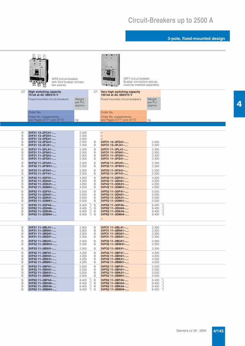
Siemens LV 30 · 2004 4/145
Circuit-Breakers up to 2500 A
3-pole, fixed-mounted design
4
DT High switching capacity 70 kA at AC 380/415 V
DT Very high switching capacity 100 kA at AC 380/415 V
Fixed-mounted circuit-breakers Weight per PU approx.
Fixed-mounted circuit-breakers Weight per PU approx.
Order No. Order No.
Order No. supplements, see Pages 4/171 and 4/172. kg
Order No. supplements, see Pages 4/171 and 4/172. kg
BBBBB
3VF31 13–2FC41–....3VF31 13–2FD41–....3VF31 13–2FE41–....3VF31 13–2FG41–....3VF31 13–2FJ41–....
2.3002.3002.3002.3002.300
BB
–––3VF31 13–3FG41–....3VF31 13–3FJ41–....
2.3002.300
BBBB
3VF31 11–2FL41–....3VF31 11–2FN41–....3VF31 11–2FQ41–....3VF31 11–2FS41–....
2.3002.3002.3002.300
BBBB
3VF31 11–3FL41–....3VF31 11–3FN41–....3VF31 11–3FQ41–....3VF31 11–3FS41–....
2.3002.3002.3002.300
BB
3VF32 11–2FU41–....3VF32 11–2FW41–....
2.3002.300
BB
3VF32 11–3FU41–....3VF32 11–3FW41–....
2.3002.300
BB
3VF33 11–2FX41–....3VF33 11–2FY41–....
2.3002.300
BB
3VF33 11–3FX41–....3VF33 11–3FY41–....
2.3002.300
BBBB
3VF42 11–2DF41–....3VF42 11–2DH41–....3VF42 11–2DK41–....3VF42 11–2DM41–....
4.2004.2004.2004.200
BBBB
3VF42 11–3DF41–....3VF42 11–3DH41–....3VF42 11–3DK41–....3VF42 11–3DM41–....
4.2004.2004.2004.200
BBBB
3VF52 11–2DF41–....3VF52 11–2DH41–....3VF52 11–2DK41–....3VF52 11–2DM41–....
5.5005.5005.5005.500
BBBB
3VF52 11–3DF41–....3VF52 11–3DH41–....3VF52 11–3DK41–....3VF52 11–3DM41–....
5.5005.5005.5005.500
BBBB
3VF62 11–2DF44–....3VF62 11–2DH44–....3VF62 11–2DK44–....3VF62 11–2DM44–....
8.4008.4008.4008.400
1)1)1)1)
BBBB
3VF62 11–3DF44–....3VF62 11–3DH44–....3VF62 11–3DK44–....3VF62 11–3DM44–....
8.4008.4008.4008.400
1)1)1)1)
– –
BBBB
3VF31 11–2BL41–....3VF31 11–2BN41–....3VF31 11–2BQ41–....3VF31 11–2BS41–....
2.3002.3002.3002.300
BBBB
3VF31 11–3BL41–....3VF31 11–3BN41–....3VF31 11–3BQ41–....3VF31 11–3BS41–....
2.3002.3002.3002.300
BB
3VF32 11–2BU41–....3VF32 11–2BW41–....
2.3002.300
BB
3VF32 11–3BU41–....3VF32 11–3BW41–....
2.3002.300
B 3VF33 11–2BX41–.... 2.300 B 3VF33 11–3BX41–.... 2.300
BBBB
3VF42 11–2BF41–....3VF42 11–2BH41–....3VF42 11–2BK41–....3VF42 11–2BM41–....
4.2004.2004.2004.200
BBBB
3VF42 11–3BF41–....3VF42 11–3BH41–....3VF42 11–3BK41–....3VF42 11–3BM41–....
4.2004.2004.2004.200
BBBB
3VF52 11–2BF41–....3VF52 11–2BH41–....3VF52 11–2BK41–....3VF52 11–2BM41–....
5.5005.5005.5005.500
BBBB
3VF52 11–3BF41–....3VF52 11–3BH41–....3VF52 11–3BK41–....3VF52 11–3BM41–....
5.5005.5005.5005.500
BBBB
3VF62 11–2BF44–....3VF62 11–2BH44–....3VF62 11–2BK44–....3VF62 11–2BM44–....
8.4008.4008.4008.400
1)1)1)1)
BBBB
3VF62 11–3BF44–....3VF62 11–3BH44–....3VF62 11–3BK44–....3VF62 11–3BM44–....
8.4008.4008.4008.400
1)1)1)1)
3VF6 circuit-breaker, with front busbar connec-tion pieces
3VF7 circuit-breaker Busbar connection pieces must be ordered separately
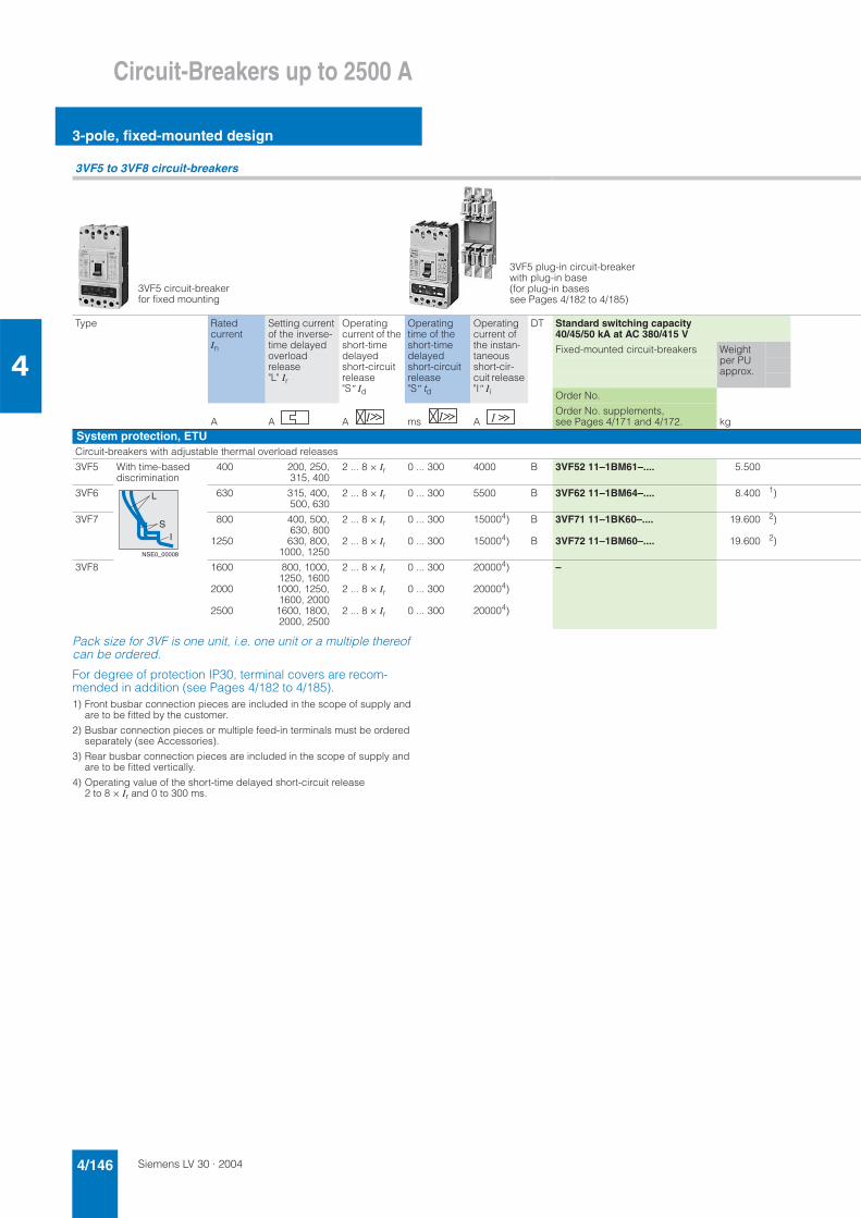
Siemens LV 30 · 20044/146
Circuit-Breakers up to 2500 A
3-pole, fixed-mounted design
4
Pack size for 3VF is one unit, i.e. one unit or a multiple thereof can be ordered.
For degree of protection IP30, terminal covers are recom-mended in addition (see Pages 4/182 to 4/185).1) Front busbar connection pieces are included in the scope of supply and
are to be fitted by the customer.
2) Busbar connection pieces or multiple feed-in terminals must be ordered separately (see Accessories).
3) Rear busbar connection pieces are included in the scope of supply and are to be fitted vertically.
4) Operating value of the short-time delayed short-circuit release 2 to 8 × Ir and 0 to 300 ms.
3VF5 to 3VF8 circuit-breakers
Type Ratedcurrent In
Setting current of the inverse-time delayed overloadrelease "L" Ir
Operatingcurrent of the short-time delayedshort-circuit release "S" Id
Operatingtime of the short-time delayedshort-circuit release "S" td
Operatingcurrent of the instan-taneousshort-cir-cuit release "I" Ii
DT Standard switching capacity 40/45/50 kA at AC 380/415 V
Fixed-mounted circuit-breakers Weight per PU approx.
Order No.
A A A ms AOrder No. supplements, see Pages 4/171 and 4/172. kg
System protection, ETUCircuit-breakers with adjustable thermal overload releases
3VF5 With time-based discrimination
400 200, 250,315, 400
2 ... 8 × Ir 0 ... 300 4000 B 3VF52 11–1BM61–.... 5.500
3VF6 630 315, 400,500, 630
2 ... 8 × Ir 0 ... 300 5500 B 3VF62 11–1BM64–.... 8.400 1)
3VF7 800
1250
400, 500,630, 800630, 800,
1000, 1250
2 ... 8 × Ir
2 ... 8 × Ir
0 ... 300
0 ... 300
150004)
150004)
B
B
3VF71 11–1BK60–....
3VF72 11–1BM60–....
19.600
19.600
2)
2)
3VF8 1600
2000
2500
800, 1000,1250, 16001000, 1250,1600, 20001600, 1800,2000, 2500
2 ... 8 × Ir
2 ... 8 × Ir
2 ... 8 × Ir
0 ... 300
0 ... 300
0 ... 300
200004)
200004)
200004)
–
3VF5 circuit-breaker for fixed mounting
3VF5 plug-in circuit-breaker with plug-in base (for plug-in bases see Pages 4/182 to 4/185)
L
SI
NSE0_00008
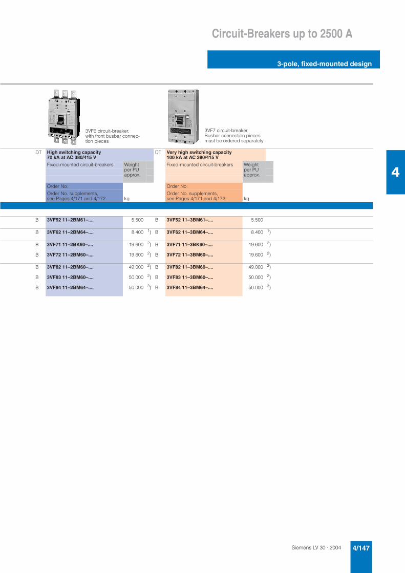
Siemens LV 30 · 2004 4/147
Circuit-Breakers up to 2500 A
3-pole, fixed-mounted design
4
DT High switching capacity 70 kA at AC 380/415 V
DT Very high switching capacity 100 kA at AC 380/415 V
Fixed-mounted circuit-breakers Weight per PU approx.
Fixed-mounted circuit-breakers Weight per PU approx.
Order No. Order No.
Order No. supplements, see Pages 4/171 and 4/172. kg
Order No. supplements, see Pages 4/171 and 4/172. kg
B 3VF52 11–2BM61–.... 5.500 B 3VF52 11–3BM61–.... 5.500
B 3VF62 11–2BM64–.... 8.400 1) B 3VF62 11–3BM64–.... 8.400 1)
B
B
3VF71 11–2BK60–....
3VF72 11–2BM60–....
19.600
19.600
2)
2)
B
B
3VF71 11–3BK60–....
3VF72 11–3BM60–....
19.600
19.600
2)
2)
B
B
B
3VF82 11–2BM60–....
3VF83 11–2BM60–....
3VF84 11–2BM64–....
49.000
50.000
50.000
2)
2)
3)
B
B
B
3VF82 11–3BM60–....
3VF83 11–3BM60–....
3VF84 11–3BM64–....
49.000
50.000
50.000
2)
2)
3)
3VF6 circuit-breaker, with front busbar connec-tion pieces
3VF7 circuit-breaker Busbar connection pieces must be ordered separately

Siemens LV 30 · 20044/148
Circuit-Breakers up to 2500 A
3-pole, fixed-mounted design
4
Pack size for 3VF is one unit, i.e. one unit or a multiple thereof can be ordered.
For degree of protection IP30, terminal covers are recom-mended in addition (see Pages 4/182 to 4/185).1) Guide values for 4-pole standard motors. The start-up data and ratings of
the motor to be protected are the determining factors.
2) System protection circuit-breakers must be used in combination with fre-quency converters or soft starters.
3) Front busbar connection pieces are included in the scope of supply and are to be fitted by the customer.
4) Busbar connection pieces must be ordered separately (see Accessories).
3VF3 to 3VF8 circuit-breakers
Type Ratedcurrent In
Rating of the three-phase motors to be protected1) at AC 50 Hz
Setting cur-rent of the inverse-timedelayed over-loadrelease "L" Ir
Operating current of the instanta-neous short-circuit release "I" Ii
Time lag classTc
DT Standard switching capacity 40/50 kA at AC 380/415 V
Fixed-mounted circuit-breakers Weight per PU approx.
380/415 V up to kW
500 V
up to kW
Order No.
Order No. supplements, see Pages 4/171 and 4/172.A A A kg
Motor protection, ETU2)without adjustable time lag class, without phase failure sensitivity
3VF3 80100160205
374575
110
5555
110132
40– 8080–100
100–160160–205
15 × Ir15 × Ir15 × Ir13 × Ir
10101010
BBBB
3VF31 11–5DN71–....3VF31 11–5DQ71–....3VF32 11–5DS71–....3VF33 11–5DU71–....
2.3002.3002.3002.300
3VF5 315 160 200 160–315 15 × Ir 20 B 3VF51 11–5DL71–.... 4.200
3VF6 500 250 355 250–500 15 × Ir 20 B 3VF61 11–5DL74–.... 4.200 3)
with adjustable time lag class, with phase failure sensitivity
3VF3 80100160205
374575
110
5555
110132
40– 8080–100
100–160160–205
15 × Ir15 × Ir15 × Ir13 × Ir
5/10/15/205/10/15/205/10/15/2010
BBBB
3VF31 11–5EN71–....3VF31 11–5EQ71–....3VF32 11–5ES71–....3VF33 11–5FU71–....
2.3002.3002.3002.300
3VF5 315 160 200 160–315 15 × Ir 10/15/20/30 B 3VF51 11–5EL71–.... 4.200
3VF6 500 250 355 250–500 15 × Ir 10/15/20/30 B 3VF61 11–5EL74–.... 4.200 3)
Starter combinations3VF3 up to 63
up to 100up to 160
304575
3755
110
– 500–1000750–1500
1200–2400
– –
3VF4 up to 125up to 160up to 200
557590
75110132
– 1000–20001250–25001500–3000
– –
3VF5 up to 200up to 250up to 315
90110160
132160200
– 1500–30001900–38002400–4800
– –
3VF6 up to 315up to 400up to 500
160200250
200250355
– 2400–48003000–60003800–7500
– –
Non-automatic circuit-breakers3VF3 up to 100
up to 160– – – 2400
2400– –
3VF4 up to 250 – – – 3000 – B 3VF42 11–5BM31–.... 4.200
3VF5 up to 400 – – – 4800 – B 3VF52 11–5BM31–.... 5.500
3VF6 up to 500up to 630
– – – 75007500
– B 3VF62 11–5BM34–.... 8.400 3)
3VF7 up to 800up to 1250
– – – 1500015000
– BB
3VF71 11–1BK30–....3VF72 11–1BM30–....
19.60019.600
4)4)
3VF8 up to 1600up to 2000
– – – 2000020000
– –
NSE0_01243
NSE0_00706
NSE0_00707
NSE0_00708

Siemens LV 30 · 2004 4/149
Circuit-Breakers up to 2500 A
3-pole, fixed-mounted design
4
DT High switching capacity 65/70 kA at AC 380/415 V
p
Fixed-mounted circuit-breakers Weight per PU approx.
Order No.
Order No. supplements, see Pages 4/171 and 4/172. kg
BBBB
3VF31 11–6DN71–....3VF31 11–6DQ71–....3VF32 11–6DS71–....3VF33 11–6DU71–....
2.3002.3002.3002.300
B 3VF51 11–6DL71–.... 4.200
B 3VF61 11–6DL74–.... 4.200 3)
BBBB
3VF31 11–6EN71–....3VF31 11–6EQ71–....3VF32 11–6ES71–....3VF33 11–6FU71–....
2.3002.3002.3002.300
B 3VF51 11–6EL71–.... 4.200
B 3VF61 11–6EL74–.... 4.200 3)
BBB
3VF31 11–6BS21–....3VF31 11–6BU21–....3VF32 11–6BW21–....
2.3002.3002.300
BBB
3VF42 11–6BH21–....3VF42 11–6BK21–....3VF42 11–6BM21–....
4.2004.2004.200
BBB
3VF51 11–6BH21–....3VF51 11–6BK21–....3VF51 11–6BM21–....
5.5005.5005.500
BBB
3VF61 11–6BH24–....3VF61 11–6BK24–....3VF61 11–6BM24–....
8.4008.4008.400
3)3)3)
BB
3VF31 11–6BS31–....3VF32 11–6BW31–....
2.3002.300
B 3VF42 11–6BM31–.... 4.200
B 3VF52 11–6BM31–.... 5.500
B 3VF61 11–6BK34–.... 8.400 3)
BB
3VF71 11–2BK30–....3VF72 11–2BM30–....
25.50025.500
4)4)
BB
3VF82 11–2BM30–....3VF83 11–2BM30–....
25.50025.500
4)4) 3VF non-automatic circuit-
breaker
3VF circuit-breakerfor starter combinations
3VF circuit-breaker for motor protection
NS
E0_
0000
2N
SE
0_00
003
NSE0_00004
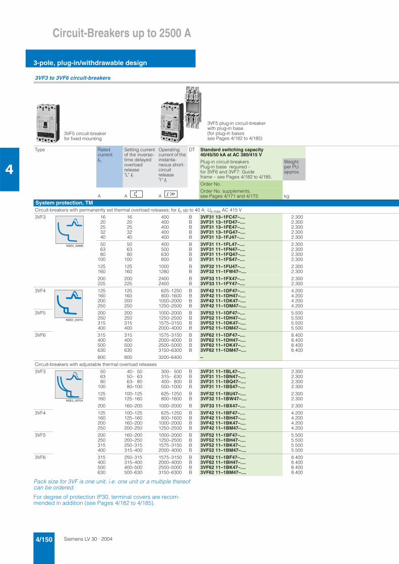
Siemens LV 30 · 20044/150
Circuit-Breakers up to 2500 A
3-pole, plug-in/withdrawable design
4
Pack size for 3VF is one unit, i.e. one unit or a multiple thereof can be ordered.
For degree of protection IP30, terminal covers are recom-mended in addition (see Pages 4/182 to 4/185).
3VF3 to 3VF6 circuit-breakers
Type Ratedcurrent In
Setting current of the inverse-time delayed overloadrelease "L" Ir
Operatingcurrent of the instanta-neous short-circuit release "I" Ii
DT Standard switching capacity 40/45/50 kA at AC 380/415 V
Plug-in circuit-breakersPlug-in base required – for 3VF6 and 3VF7: Guideframe – see Pages 4/182 to 4/185.
Weight per PU approx.
Order No.
A A AOrder No. supplements, see Pages 4/171 and 4/172. kg
System protection, TMCircuit-breakers with permanently set thermal overload releases; for In up to 40 A: Ue max AC 415 V
3VF3 1620253240
1620253240
400400400400400
BBBBB
3VF31 13–1FC47–....3VF31 13–1FD47–....3VF31 13–1FE47–....3VF31 13–1FG47–....3VF31 13–1FJ47–....
2.3002.3002.3002.3002.300
506380
100
506380
100
400500630800
BBBB
3VF31 11–1FL47–....3VF31 11–1FN47–....3VF31 11–1FQ47–....3VF31 11–1FS47–....
2.3002.3002.3002.300
125160
125160
10001280
BB
3VF32 11–1FU47–....3VF32 11–1FW47–....
2.3002.300
200225
200225
24002400
BB
3VF33 11–1FX47–....3VF33 11–1FY47–....
2.3002.300
3VF4 125160200250
125160200250
625–1250800–1600
1000–20001250–2500
BBBB
3VF42 11–1DF47–....3VF42 11–1DH47–....3VF42 11–1DK47–....3VF42 11–1DM47–....
4.2004.2004.2004.200
3VF5 200250315400
200250315400
1000–20001250–25001575–31502000–4000
BBBB
3VF52 11–1DF47–....3VF52 11–1DH47–....3VF52 11–1DK47–....3VF52 11–1DM47–....
5.5005.5005.5005.500
3VF6 315400500630
315400500630
1575–31502000–40002500–50003150–6300
BBBB
3VF62 11–1DF47–....3VF62 11–1DH47–....3VF62 11–1DK47–....3VF62 11–1DM47–....
8.4008.4008.4008.400
800 800 3200–6400 –
Circuit-breakers with adjustable thermal overload releases
3VF3 506380
100
40– 5050– 6363– 8080–100
300– 500315– 630400– 800500–1000
BBBB
3VF31 11–1BL47–....3VF31 11–1BN47–....3VF31 11–1BQ47–....3VF31 11–1BS47–....
2.3002.3002.3002.300
125160
100–125125–160
625–1250800–1600
BB
3VF32 11–1BU47–....3VF32 11–1BW47–....
2.3002.300
200 160–200 1000–2000 B 3VF33 11–1BX47–.... 2.300
3VF4 125160200250
100–125125–160160–200200–250
625–1250800–1600
1000–20001250–2500
BBBB
3VF42 11–1BF47–....3VF42 11–1BH47–....3VF42 11–1BK47–....3VF42 11–1BM47–....
4.2004.2004.2004.200
3VF5 200250315400
160–200200–250250–315315–400
1000–20001250–25001575–31502000–4000
BBBB
3VF52 11–1BF47–....3VF52 11–1BH47–....3VF52 11–1BK47–....3VF52 11–1BM47–....
5.5005.5005.5005.500
3VF6 315400500630
250–315315–400400–500500–630
1575–31502000–40002500–50003150–6300
BBBB
3VF62 11–1BF47–....3VF62 11–1BH47–....3VF62 11–1BK47–....3VF62 11–1BM47–....
8.4008.4008.4008.400
3VF5 circuit-breaker for fixed mounting
3VF5 plug-in circuit-breaker with plug-in base (for plug-in bases see Pages 4/182 to 4/185)
NSE0_00695
NSE0_00015
NSE0_00704
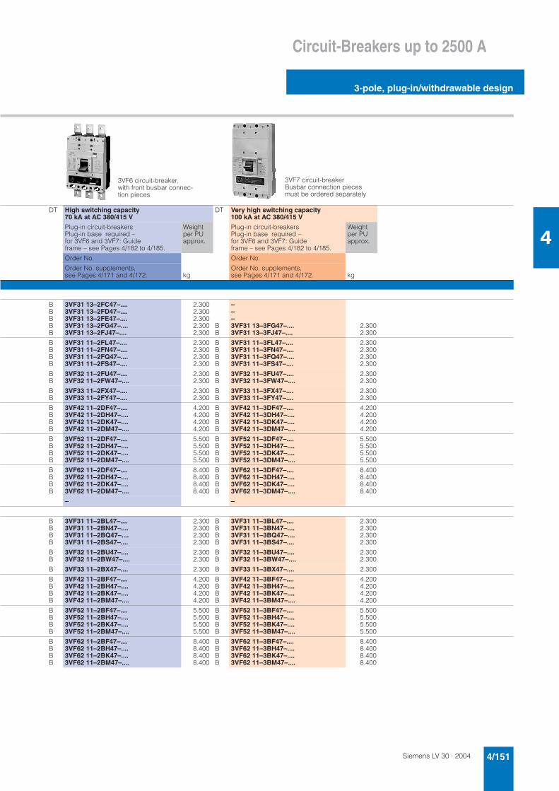
Siemens LV 30 · 2004 4/151
Circuit-Breakers up to 2500 A
3-pole, plug-in/withdrawable design
4
DT High switching capacity 70 kA at AC 380/415 V
DT Very high switching capacity 100 kA at AC 380/415 V
Plug-in circuit-breakersPlug-in base required – for 3VF6 and 3VF7: Guideframe – see Pages 4/182 to 4/185.
Weight per PU approx.
Plug-in circuit-breakersPlug-in base required – for 3VF6 and 3VF7: Guideframe – see Pages 4/182 to 4/185.
Weight per PU approx.
Order No. Order No.
Order No. supplements, see Pages 4/171 and 4/172. kg
Order No. supplements, see Pages 4/171 and 4/172. kg
BBBBB
3VF31 13–2FC47–....3VF31 13–2FD47–....3VF31 13–2FE47–....3VF31 13–2FG47–....3VF31 13–2FJ47–....
2.3002.3002.3002.3002.300
BB
–––3VF31 13–3FG47–....3VF31 13–3FJ47–....
2.3002.300
BBBB
3VF31 11–2FL47–....3VF31 11–2FN47–....3VF31 11–2FQ47–....3VF31 11–2FS47–....
2.3002.3002.3002.300
BBBB
3VF31 11–3FL47–....3VF31 11–3FN47–....3VF31 11–3FQ47–....3VF31 11–3FS47–....
2.3002.3002.3002.300
BB
3VF32 11–2FU47–....3VF32 11–2FW47–....
2.3002.300
BB
3VF32 11–3FU47–....3VF32 11–3FW47–....
2.3002.300
BB
3VF33 11–2FX47–....3VF33 11–2FY47–....
2.3002.300
BB
3VF33 11–3FX47–....3VF33 11–3FY47–....
2.3002.300
BBBB
3VF42 11–2DF47–....3VF42 11–2DH47–....3VF42 11–2DK47–....3VF42 11–2DM47–....
4.2004.2004.2004.200
BBBB
3VF42 11–3DF47–....3VF42 11–3DH47–....3VF42 11–3DK47–....3VF42 11–3DM47–....
4.2004.2004.2004.200
BBBB
3VF52 11–2DF47–....3VF52 11–2DH47–....3VF52 11–2DK47–....3VF52 11–2DM47–....
5.5005.5005.5005.500
BBBB
3VF52 11–3DF47–....3VF52 11–3DH47–....3VF52 11–3DK47–....3VF52 11–3DM47–....
5.5005.5005.5005.500
BBBB
3VF62 11–2DF47–....3VF62 11–2DH47–....3VF62 11–2DK47–....3VF62 11–2DM47–....
8.4008.4008.4008.400
BBBB
3VF62 11–3DF47–....3VF62 11–3DH47–....3VF62 11–3DK47–....3VF62 11–3DM47–....
8.4008.4008.4008.400
– –
BBBB
3VF31 11–2BL47–....3VF31 11–2BN47–....3VF31 11–2BQ47–....3VF31 11–2BS47–....
2.3002.3002.3002.300
BBBB
3VF31 11–3BL47–....3VF31 11–3BN47–....3VF31 11–3BQ47–....3VF31 11–3BS47–....
2.3002.3002.3002.300
BB
3VF32 11–2BU47–....3VF32 11–2BW47–....
2.3002.300
BB
3VF32 11–3BU47–....3VF32 11–3BW47–....
2.3002.300
B 3VF33 11–2BX47–.... 2.300 B 3VF33 11–3BX47–.... 2.300
BBBB
3VF42 11–2BF47–....3VF42 11–2BH47–....3VF42 11–2BK47–....3VF42 11–2BM47–....
4.2004.2004.2004.200
BBBB
3VF42 11–3BF47–....3VF42 11–3BH47–....3VF42 11–3BK47–....3VF42 11–3BM47–....
4.2004.2004.2004.200
BBBB
3VF52 11–2BF47–....3VF52 11–2BH47–....3VF52 11–2BK47–....3VF52 11–2BM47–....
5.5005.5005.5005.500
BBBB
3VF52 11–3BF47–....3VF52 11–3BH47–....3VF52 11–3BK47–....3VF52 11–3BM47–....
5.5005.5005.5005.500
BBBB
3VF62 11–2BF47–....3VF62 11–2BH47–....3VF62 11–2BK47–....3VF62 11–2BM47–....
8.4008.4008.4008.400
BBBB
3VF62 11–3BF47–....3VF62 11–3BH47–....3VF62 11–3BK47–....3VF62 11–3BM47–....
8.4008.4008.4008.400
3VF6 circuit-breaker, with front busbar connec-tion pieces
3VF7 circuit-breaker Busbar connection pieces must be ordered separately
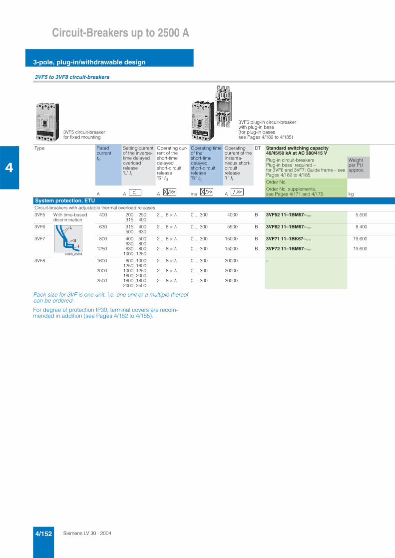
Siemens LV 30 · 20044/152
Circuit-Breakers up to 2500 A
3-pole, plug-in/withdrawable design
4
Pack size for 3VF is one unit, i.e. one unit or a multiple thereof can be ordered.
For degree of protection IP30, terminal covers are recom-mended in addition (see Pages 4/182 to 4/185).
3VF5 to 3VF8 circuit-breakers
Type Ratedcurrent In
Setting current of the inverse-time delayed overloadrelease "L" Ir
Operating cur-rent of the short-time delayedshort-circuit release "S" Id
Operating time of the short-time delayedshort-circuit release "S" td
Operatingcurrent of the instanta-neous short-circuit release "I" Ii
DT Standard switching capacity 40/45/50 kA at AC 380/415 V
Plug-in circuit-breakersPlug-in base required – for 3VF6 and 3VF7: Guide frame – see Pages 4/182 to 4/185.
Weight per PU approx.
Order No.
A A A ms AOrder No. supplements, see Pages 4/171 and 4/172. kg
System protection, ETUCircuit-breakers with adjustable thermal overload releases
3VF5 With time-based discrimination
400 200, 250, 315, 400
2 ... 8 × Ir 0 ... 300 4000 B 3VF52 11–1BM67–.... 5.500
3VF6 630 315, 400, 500, 630
2 ... 8 × Ir 0 ... 300 5500 B 3VF62 11–1BM67–.... 8.400
3VF7 800
1250
400, 500, 630, 800630, 800,
1000, 1250
2 ... 8 × Ir
2 ... 8 × Ir
0 ... 300
0 ... 300
15000
15000
B
B
3VF71 11–1BK67–....
3VF72 11–1BM67–....
19.600
19.600
3VF8 1600
2000
2500
800, 1000, 1250, 16001000, 1250, 1600, 20001600, 1800, 2000, 2500
2 ... 8 × Ir
2 ... 8 × Ir
2 ... 8 × Ir
0 ... 300
0 ... 300
0 ... 300
20000
20000
20000
–
3VF5 circuit-breaker for fixed mounting
3VF5 plug-in circuit-breaker with plug-in base (for plug-in bases see Pages 4/182 to 4/185)
L
SI
NSE0_00008
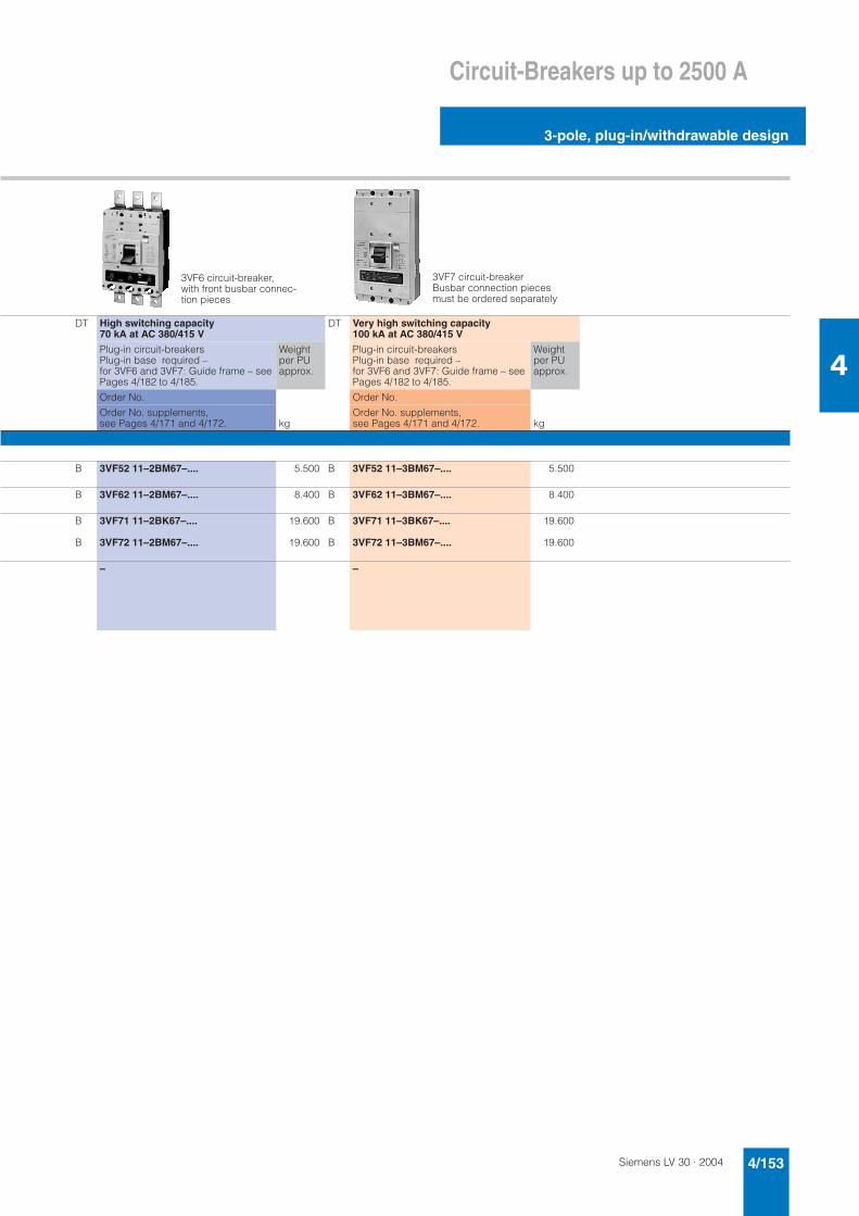
Siemens LV 30 · 2004 4/153
Circuit-Breakers up to 2500 A
3-pole, plug-in/withdrawable design
4
DT High switching capacity 70 kA at AC 380/415 V
DT Very high switching capacity 100 kA at AC 380/415 V
Plug-in circuit-breakersPlug-in base required – for 3VF6 and 3VF7: Guide frame – see Pages 4/182 to 4/185.
Weight per PU approx.
Plug-in circuit-breakersPlug-in base required – for 3VF6 and 3VF7: Guide frame – see Pages 4/182 to 4/185.
Weight per PU approx.
Order No. Order No.
Order No. supplements, see Pages 4/171 and 4/172. kg
Order No. supplements, see Pages 4/171 and 4/172. kg
B 3VF52 11–2BM67–.... 5.500 B 3VF52 11–3BM67–.... 5.500
B 3VF62 11–2BM67–.... 8.400 B 3VF62 11–3BM67–.... 8.400
B
B
3VF71 11–2BK67–....
3VF72 11–2BM67–....
19.600
19.600
B
B
3VF71 11–3BK67–....
3VF72 11–3BM67–....
19.600
19.600
– –
3VF6 circuit-breaker, with front busbar connec-tion pieces
3VF7 circuit-breaker Busbar connection pieces must be ordered separately
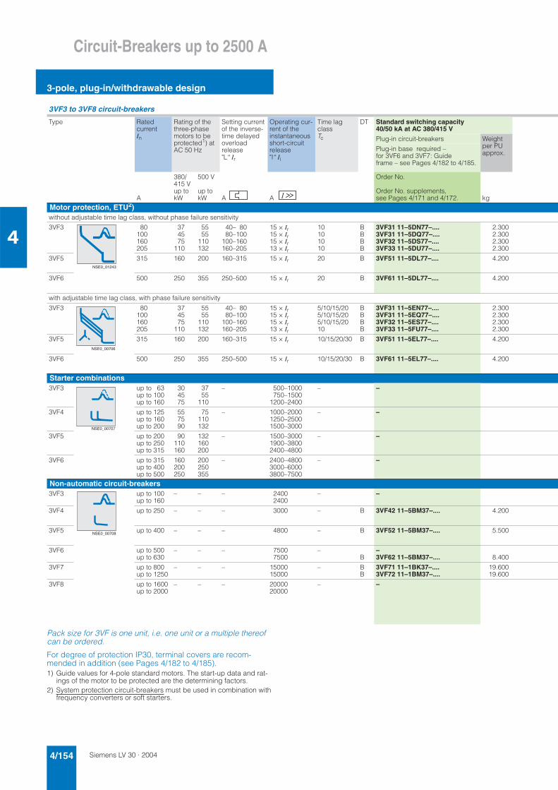
Siemens LV 30 · 20044/154
Circuit-Breakers up to 2500 A
3-pole, plug-in/withdrawable design
4
Pack size for 3VF is one unit, i.e. one unit or a multiple thereof can be ordered.
For degree of protection IP30, terminal covers are recom-mended in addition (see Pages 4/182 to 4/185).1) Guide values for 4-pole standard motors. The start-up data and rat-
ings of the motor to be protected are the determining factors.2) System protection circuit-breakers must be used in combination with
frequency converters or soft starters.
3VF3 to 3VF8 circuit-breakers
Type Ratedcurrent In
Rating of the three-phase motors to be protected1) at AC 50 Hz
Setting current of the inverse-time delayed overloadrelease "L" Ir
Operating cur-rent of the instantaneousshort-circuit release "I" Ii
Time lag classTc
DT Standard switching capacity 40/50 kA at AC 380/415 V
Plug-in circuit-breakers Weight per PU approx.
Plug-in base required – for 3VF6 and 3VF7: Guideframe – see Pages 4/182 to 4/185.
380/415 V up to kW
500 V
up to kW
Order No.
Order No. supplements, see Pages 4/171 and 4/172.A A A kg
Motor protection, ETU2)without adjustable time lag class, without phase failure sensitivity
3VF3 80100160205
374575
110
5555
110132
40– 8080–100
100–160160–205
15 × Ir15 × Ir15 × Ir13 × Ir
10101010
BBBB
3VF31 11–5DN77–....3VF31 11–5DQ77–....3VF32 11–5DS77–....3VF33 11–5DU77–....
2.3002.3002.3002.300
3VF5 315 160 200 160–315 15 × Ir 20 B 3VF51 11–5DL77–.... 4.200
3VF6 500 250 355 250–500 15 × Ir 20 B 3VF61 11–5DL77–.... 4.200
with adjustable time lag class, with phase failure sensitivity
3VF3 80100160205
374575
110
5555
110132
40– 8080–100
100–160160–205
15 × Ir15 × Ir15 × Ir13 × Ir
5/10/15/205/10/15/205/10/15/2010
BBBB
3VF31 11–5EN77–....3VF31 11–5EQ77–....3VF32 11–5ES77–....3VF33 11–5FU77–....
2.3002.3002.3002.300
3VF5 315 160 200 160–315 15 × Ir 10/15/20/30 B 3VF51 11–5EL77–.... 4.200
3VF6 500 250 355 250–500 15 × Ir 10/15/20/30 B 3VF61 11–5EL77–.... 4.200
Starter combinations3VF3 up to 63
up to 100up to 160
304575
3755
110
– 500–1000750–1500
1200–2400
– –
3VF4 up to 125up to 160up to 200
557590
75110132
– 1000–20001250–25001500–3000
– –
3VF5 up to 200up to 250up to 315
90110160
132160200
– 1500–30001900–38002400–4800
– –
3VF6 up to 315up to 400up to 500
160200250
200250355
– 2400–48003000–60003800–7500
– –
Non-automatic circuit-breakers3VF3 up to 100
up to 160– – – 2400
2400– –
3VF4 up to 250 – – – 3000 – B 3VF42 11–5BM37–.... 4.200
3VF5 up to 400 – – – 4800 – B 3VF52 11–5BM37–.... 5.500
3VF6 up to 500up to 630
– – – 75007500
–B
–3VF62 11–5BM37–.... 8.400
3VF7 up to 800up to 1250
– – – 1500015000
– BB
3VF71 11–1BK37–....3VF72 11–1BM37–....
19.60019.600
3VF8 up to 1600up to 2000
– – – 2000020000
– –
NSE0_01243
NSE0_00706
NSE0_00707
NSE0_00708
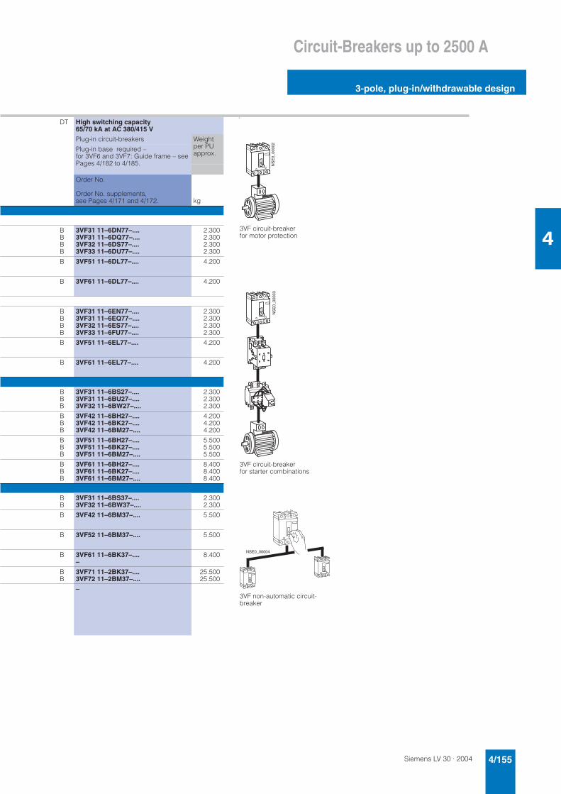
Siemens LV 30 · 2004 4/155
Circuit-Breakers up to 2500 A
3-pole, plug-in/withdrawable design
4
DT High switching capacity 65/70 kA at AC 380/415 V
p
Plug-in circuit-breakers Weight per PU approx.
Plug-in base required – for 3VF6 and 3VF7: Guide frame – see Pages 4/182 to 4/185.
Order No.
Order No. supplements, see Pages 4/171 and 4/172. kg
BBBB
3VF31 11–6DN77–....3VF31 11–6DQ77–....3VF32 11–6DS77–....3VF33 11–6DU77–....
2.3002.3002.3002.300
B 3VF51 11–6DL77–.... 4.200
B 3VF61 11–6DL77–.... 4.200
BBBB
3VF31 11–6EN77–....3VF31 11–6EQ77–....3VF32 11–6ES77–....3VF33 11–6FU77–....
2.3002.3002.3002.300
B 3VF51 11–6EL77–.... 4.200
B 3VF61 11–6EL77–.... 4.200
BBB
3VF31 11–6BS27–....3VF31 11–6BU27–....3VF32 11–6BW27–....
2.3002.3002.300
BBB
3VF42 11–6BH27–....3VF42 11–6BK27–....3VF42 11–6BM27–....
4.2004.2004.200
BBB
3VF51 11–6BH27–....3VF51 11–6BK27–....3VF51 11–6BM27–....
5.5005.5005.500
BBB
3VF61 11–6BH27–....3VF61 11–6BK27–....3VF61 11–6BM27–....
8.4008.4008.400
BB
3VF31 11–6BS37–....3VF32 11–6BW37–....
2.3002.300
B 3VF42 11–6BM37–.... 5.500
B 3VF52 11–6BM37–.... 5.500
B 3VF61 11–6BK37–....–
8.400
BB
3VF71 11–2BK37–....3VF72 11–2BM37–....
25.50025.500
–3VF non-automatic circuit-breaker
3VF circuit-breakerfor starter combinations
3VF circuit-breaker for motor protection
NS
E0_
0000
2N
SE
0_00
003
NSE0_00004
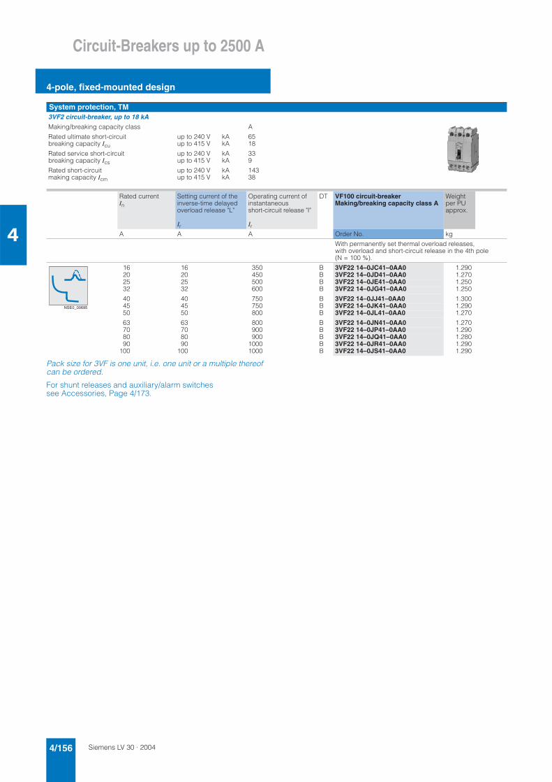
Siemens LV 30 · 20044/156
Circuit-Breakers up to 2500 A
4-pole, fixed-mounted design
4
Pack size for 3VF is one unit, i.e. one unit or a multiple thereof can be ordered.
For shunt releases and auxiliary/alarm switches see Accessories, Page 4/173.
System protection, TM3VF2 circuit-breaker, up to 18 kAMaking/breaking capacity class A
Rated ultimate short-circuitbreaking capacity Icu
up to 240 Vup to 415 V
kAkA
6518
Rated service short-circuit breaking capacity Ics
up to 240 Vup to 415 V
kAkA
339
Rated short-circuit making capacity Icm
up to 240 Vup to 415 V
kAkA
14338
Rated current In
Setting current of the inverse-time delayed overload release "L"
Ir
Operating current of instantaneousshort-circuit release "I"
Ir
DT VF100 circuit-breakerMaking/breaking capacity class A
Weight per PU approx.
A A A Order No. kg
With permanently set thermal overload releases, with overload and short-circuit release in the 4th pole (N = 100 %).
16 16 350 B 3VF22 14–0JC41–0AA0 1.29020 20 450 B 3VF22 14–0JD41–0AA0 1.27025 25 500 B 3VF22 14–0JE41–0AA0 1.25032 32 600 B 3VF22 14–0JG41–0AA0 1.250
40 40 750 B 3VF22 14–0JJ41–0AA0 1.30045 45 750 B 3VF22 14–0JK41–0AA0 1.29050 50 800 B 3VF22 14–0JL41–0AA0 1.270
63 63 800 B 3VF22 14–0JN41–0AA0 1.27070 70 900 B 3VF22 14–0JP41–0AA0 1.29080 80 900 B 3VF22 14–0JQ41–0AA0 1.28090 90 1000 B 3VF22 14–0JR41–0AA0 1.290
100 100 1000 B 3VF22 14–0JS41–0AA0 1.290
NSE0_00695
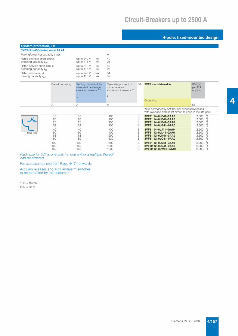
Siemens LV 30 · 2004 4/157
Circuit-Breakers up to 2500 A
4-pole, fixed-mounted design
4
Pack size for 3VF is one unit, i.e. one unit or a multiple thereof can be ordered.
For accessories, see from Page 4/174 onwards.
Auxiliary releases and auxiliary/alarm switches to be retrofitted by the customer.
1) N = 100 %.
2) N = 60 %.
System protection, TM3VF3 circuit-breaker, up to 25 kAMaking/breaking capacity class A
Rated ultimate short-circuitbreaking capacity Icu
up to 240 Vup to 415 V
kAkA
4025
Rated service short-circuit breaking capacity Ics
up to 240 Vup to 415 V
kAkA
4025
Rated short-circuit making capacity Icm
up to 240 Vup to 415 V
kAkA
8452
Rated current In Setting current of the inverse-time delayed overload release "L"
Ir
Operating current of instantaneousshort-circuit release "I"
Ii
DT 3VF3 circuit-breaker Weight per PU approx.
Order No.
A A A kg
With permanently set thermal overload releases, with overload and short-circuit release in the 4th pole
16 16 400 B 3VF31 14–0JC41–0AA0 2.600 1)20 20 400 B 3VF31 14–0JD41–0AA0 2.600 1)25 25 400 B 3VF31 14–0JE41–0AA0 2.600 1)32 32 400 B 3VF31 14–0JG41–0AA0 2.600 1)
40 40 400 B 3VF31 14–0JJ41–0AA0 2.600 1)50 50 400 B 3VF31 12–0JL41–0AA0 2.600 1)63 63 500 B 3VF31 12–0JN41–0AA0 2.600 1)80 80 630 B 3VF31 12–0JQ41–0AA0 2.600 1)
100 100 800 B 3VF31 12–0JS41–0AA0 2.600 1)125 125 1000 B 3VF32 12–0JU41–0AA0 2.600 2)160 160 1280 B 3VF32 12–0JW41–0AA0 2.600 2)
NSE0_00695
Siemens LV 30 · 20044/158
Circuit-Breakers up to 2500 A
4-pole, fixed-mounted design
4
Pack size for 3VF is one unit, i.e. one unit or a multiple thereof can be ordered.
For degree of protection IP30, terminal covers are recom-mended in addition (see Pages 4/182 to 4/185).
1) Front busbar connection pieces are included in the scope of supply and are to be fitted by the customer.
2) 50 kA at 380/415 V.
3) N = 100 %.
4) N = 60 %. To be observed in DC applications.
5) Front busbar connection pieces are included in the scope of supply and are to be fitted by the customer.
3VF3 to 3VF6 circuit-breakers
Type Ratedcurrent In
Setting current of the inverse-time delayed overloadrelease "L" Ir
Operatingcurrent of the short-time delayedshort-circuit release "S" Id
Operatingtime of the short-time delayedshort-circuit release "S" td
Operatingcurrent of the instanta-neous short-circuit release "I" Ii
DT Standard switching capacity 40/45/50 kA at AC 380/415 V
Fixed-mounted circuit-breakers Weight per PU approx.
Order No.
A A A ms AOrder No. supplements, see Pages 4/171 and 4/172. kg
System protection, TMwithout overload release and short-circuit release in the 4th pole (N); at In up to 40 A: Ue max. AC 415 V
3VF3 1620253240
1620253240
– – 400400400400400
BBBBB
3VF31 14–1RC41–....3VF31 14–1RD41–....3VF31 14–1RE41–....3VF31 14–1RG41–....3VF31 14–1RJ41–....
2.6002.6002.6002.6002.600
506380
100
40– 5050– 6363– 8080–100
– – 300– 500315– 630400– 800500–1000
BBBB
3VF31 12–1ML41–....3VF31 12–1MN41–....3VF31 12–1MQ41–....3VF31 12–1MS41–....
2.6002.6002.6002.600
125160
100–125125–160
630–1250800–1600
BB
3VF32 12–1MU41–....3VF32 12–1MW41–....
2.6002.600
200225
160–200225
1000–20002400
BB
3VF33 12–1MX41–....3VF33 12–1RY41–....
2.6002.600
3VF4 125160200250
100–125125–160160–200200–250
– – 630–1250800–1600
1000–20001250–2500
BBBB
3VF42 12–1MF41–....3VF42 12–1MH41–....3VF42 12–1MK41–....3VF42 12–1MM41–....
5.5005.5005.5005.500
3VF5 200250315400
160–200200–250250–315315–400
– – 1000–20001250–25001575–31502000–4000
BBBB
3VF52 12–1MF41–....3VF52 12–1MH41–....3VF52 12–1MK41–....3VF52 12–1MM41–....
6.5006.5006.5006.500
3VF6 315400500630
250–315315–400400–500500–630
– – 1575–31502000–40002500–50003150–6300
BBBB
3VF62 12–1MF44–....3VF62 12–1MH44–....3VF62 12–1MK44–....3VF62 12–1MM44–....
11.00011.00011.00011.000
1)1)1)1)
800 800 – – 3200–6400 B 3VF63 12–2TQ44–.... 11.000 2)
with overload and short-circuit releases in the 4th pole (N); at In up to 40 A: Ue max AC 415 V
3VF3 1620253240
1620253240
– – 4003)4003)4003)4003)4003)
BBBBB
3VF31 14–1JC41–....3VF31 14–1JD41–....3VF31 14–1JE41–....3VF31 14–1JG41–....3VF31 14–1JJ41–....
2.6002.6002.6002.6002.600
506380
100
40– 5050– 6363– 8080–100
– – 300– 5003)315– 6303)400– 8003)500–10003)
BBBB
3VF31 12–1HL41–....3VF31 12–1HN41–....3VF31 12–1HQ41–....3VF31 12–1HS41–....
2.6002.6002.6002.600
125160
100–125125–160
630–12504)800–16004)
BB
3VF32 12–1HU41–....3VF32 12–1HW41–....
2.6002.600
200225
160–200225
1000–20004)24004)
BB
3VF33 12–1HX41–....3VF33 12–1JY41–....
2.6002.600
3VF4 200250
160–200200–250
– – 1000–20004)1250–25004)
BB
3VF42 12–1HK41–....3VF42 12–1HM41–....
5.5005.500
3VF5 315400
250–315315–400
– – 1575–31504)2000–40004)
BB
3VF52 12–1HK41–....3VF52 12–1HM41–....
6.5006.500
3VF6 500630
400–500500–630
– – 2500–50004)3150–63004)
BB
3VF62 12–1HK44–....3VF62 12–1HM44–....
11.00011.000
5)5)
800 800 – – 3200–64004) B 3VF63 12–2LQ44–.... 11.000 2)5)
NSE0_00704
NSE0_00704
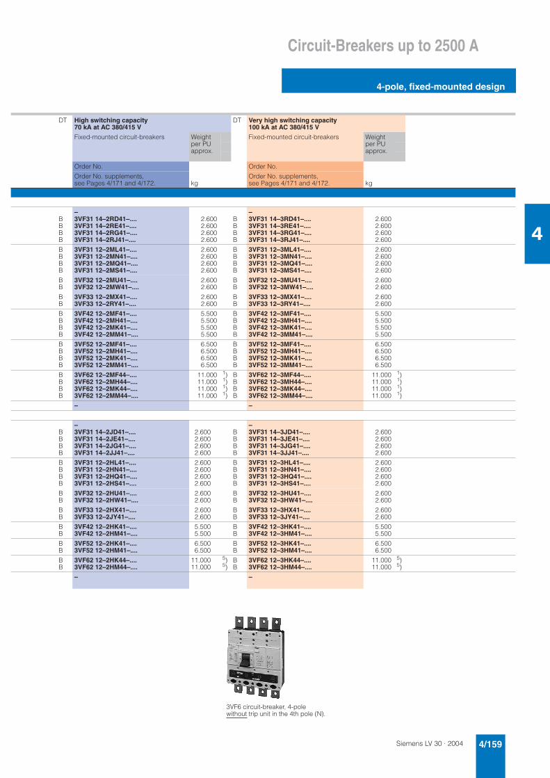
Siemens LV 30 · 2004 4/159
Circuit-Breakers up to 2500 A
4-pole, fixed-mounted design
4
DT High switching capacity 70 kA at AC 380/415 V
DT Very high switching capacity 100 kA at AC 380/415 V
Fixed-mounted circuit-breakers Weight per PU approx.
Fixed-mounted circuit-breakers Weight per PU approx.
Order No. Order No.
Order No. supplements, see Pages 4/171 and 4/172. kg
Order No. supplements, see Pages 4/171 and 4/172. kg
BBBB
–3VF31 14–2RD41–....3VF31 14–2RE41–....3VF31 14–2RG41–....3VF31 14–2RJ41–....
2.6002.6002.6002.600
BBBB
–3VF31 14–3RD41–....3VF31 14–3RE41–....3VF31 14–3RG41–....3VF31 14–3RJ41–....
2.6002.6002.6002.600
BBBB
3VF31 12–2ML41–....3VF31 12–2MN41–....3VF31 12–2MQ41–....3VF31 12–2MS41–....
2.6002.6002.6002.600
BBBB
3VF31 12–3ML41–....3VF31 12–3MN41–....3VF31 12–3MQ41–....3VF31 12–3MS41–....
2.6002.6002.6002.600
BB
3VF32 12–2MU41–....3VF32 12–2MW41–....
2.6002.600
BB
3VF32 12–3MU41–....3VF32 12–3MW41–....
2.6002.600
BB
3VF33 12–2MX41–....3VF33 12–2RY41–....
2.6002.600
BB
3VF33 12–3MX41–....3VF33 12–3RY41–....
2.6002.600
BBBB
3VF42 12–2MF41–....3VF42 12–2MH41–....3VF42 12–2MK41–....3VF42 12–2MM41–....
5.5005.5005.5005.500
BBBB
3VF42 12–3MF41–....3VF42 12–3MH41–....3VF42 12–3MK41–....3VF42 12–3MM41–....
5.5005.5005.5005.500
BBBB
3VF52 12–2MF41–....3VF52 12–2MH41–....3VF52 12–2MK41–....3VF52 12–2MM41–....
6.5006.5006.5006.500
BBBB
3VF52 12–3MF41–....3VF52 12–3MH41–....3VF52 12–3MK41–....3VF52 12–3MM41–....
6.5006.5006.5006.500
BBBB
3VF62 12–2MF44–....3VF62 12–2MH44–....3VF62 12–2MK44–....3VF62 12–2MM44–....
11.00011.00011.00011.000
1)1)1)1)
BBBB
3VF62 12–3MF44–....3VF62 12–3MH44–....3VF62 12–3MK44–....3VF62 12–3MM44–....
11.00011.00011.00011.000
1)1)1)1)
– –
BBBB
–3VF31 14–2JD41–....3VF31 14–2JE41–....3VF31 14–2JG41–....3VF31 14–2JJ41–....
2.6002.6002.6002.600
BBBB
–3VF31 14–3JD41–....3VF31 14–3JE41–....3VF31 14–3JG41–....3VF31 14–3JJ41–....
2.6002.6002.6002.600
BBBB
3VF31 12–2HL41–....3VF31 12–2HN41–....3VF31 12–2HQ41–....3VF31 12–2HS41–....
2.6002.6002.6002.600
BBBB
3VF31 12–3HL41–....3VF31 12–3HN41–....3VF31 12–3HQ41–....3VF31 12–3HS41–....
2.6002.6002.6002.600
BB
3VF32 12–2HU41–....3VF32 12–2HW41–....
2.6002.600
BB
3VF32 12–3HU41–....3VF32 12–3HW41–....
2.6002.600
BB
3VF33 12–2HX41–....3VF33 12–2JY41–....
2.6002.600
BB
3VF33 12–3HX41–....3VF33 12–3JY41–....
2.6002.600
BB
3VF42 12–2HK41–....3VF42 12–2HM41–....
5.5005.500
BB
3VF42 12–3HK41–....3VF42 12–3HM41–....
5.5005.500
BB
3VF52 12–2HK41–....3VF52 12–2HM41–....
6.5006.500
BB
3VF52 12–3HK41–....3VF52 12–3HM41–....
6.5006.500
BB
3VF62 12–2HK44–....3VF62 12–2HM44–....
11.00011.000
5)5)
BB
3VF62 12–3HK44–....3VF62 12–3HM44–....
11.00011.000
5)5)
– –
3VF6 circuit-breaker, 4-pole without trip unit in the 4th pole (N).
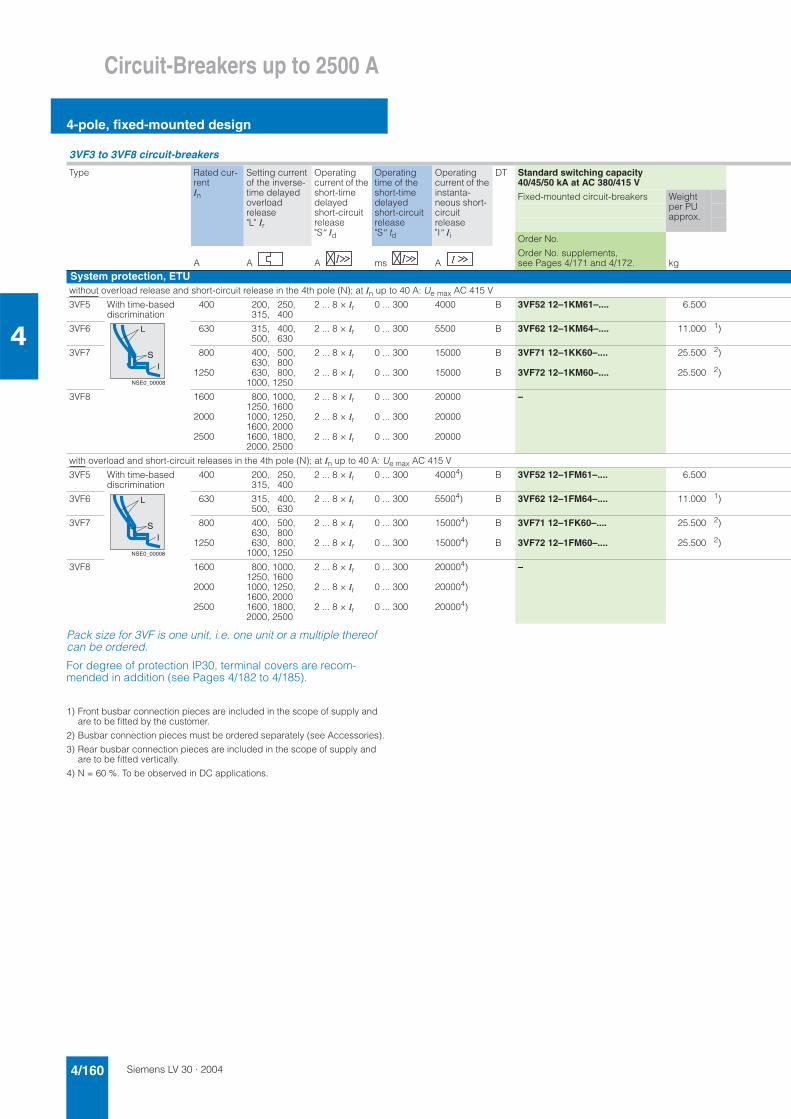
Siemens LV 30 · 20044/160
Circuit-Breakers up to 2500 A
4-pole, fixed-mounted design
4
Pack size for 3VF is one unit, i.e. one unit or a multiple thereof can be ordered.
For degree of protection IP30, terminal covers are recom-mended in addition (see Pages 4/182 to 4/185).
1) Front busbar connection pieces are included in the scope of supply and are to be fitted by the customer.
2) Busbar connection pieces must be ordered separately (see Accessories).
3) Rear busbar connection pieces are included in the scope of supply and are to be fitted vertically.
4) N = 60 %. To be observed in DC applications.
3VF3 to 3VF8 circuit-breakers
Type Rated cur-rent In
Setting current of the inverse-time delayed overloadrelease "L" Ir
Operatingcurrent of the short-time delayedshort-circuit release "S" Id
Operatingtime of the short-time delayedshort-circuit release "S" td
Operatingcurrent of the instanta-neous short-circuit release "I" Ii
DT Standard switching capacity 40/45/50 kA at AC 380/415 V
Fixed-mounted circuit-breakers Weight per PU approx.
Order No.
A A A ms AOrder No. supplements, see Pages 4/171 and 4/172. kg
System protection, ETUwithout overload release and short-circuit release in the 4th pole (N); at In up to 40 A: Ue max AC 415 V
3VF5 With time-based discrimination
400 200, 250, 315, 400
2 ... 8 × Ir 0 ... 300 4000 B 3VF52 12–1KM61–.... 6.500
3VF6 630 315, 400, 500, 630
2 ... 8 × Ir 0 ... 300 5500 B 3VF62 12–1KM64–.... 11.000 1)
3VF7 800
1250
400, 500, 630, 800630, 800,
1000, 1250
2 ... 8 × Ir
2 ... 8 × Ir
0 ... 300
0 ... 300
15000
15000
B
B
3VF71 12–1KK60–....
3VF72 12–1KM60–....
25.500
25.500
2)
2)
3VF8 1600
2000
2500
800, 1000, 1250, 1600 1000, 1250, 1600, 2000 1600, 1800, 2000, 2500
2 ... 8 × Ir
2 ... 8 × Ir
2 ... 8 × Ir
0 ... 300
0 ... 300
0 ... 300
20000
20000
20000
–
with overload and short-circuit releases in the 4th pole (N); at In up to 40 A: Ue max AC 415 V
3VF5 With time-based discrimination
400 200, 250, 315, 400
2 ... 8 × Ir 0 ... 300 40004) B 3VF52 12–1FM61–.... 6.500
3VF6 630 315, 400, 500, 630
2 ... 8 × Ir 0 ... 300 55004) B 3VF62 12–1FM64–.... 11.000 1)
3VF7 800
1250
400, 500, 630, 800630, 800,
1000, 1250
2 ... 8 × Ir
2 ... 8 × Ir
0 ... 300
0 ... 300
150004)
150004)
B
B
3VF71 12–1FK60–....
3VF72 12–1FM60–....
25.500
25.500
2)
2)
3VF8 1600
2000
2500
800, 1000, 1250, 16001000, 1250, 1600, 20001600, 1800, 2000, 2500
2 ... 8 × Ir
2 ... 8 × Ir
2 ... 8 × Ir
0 ... 300
0 ... 300
0 ... 300
200004)
200004)
200004)
–
L
SI
NSE0_00008
L
SI
NSE0_00008
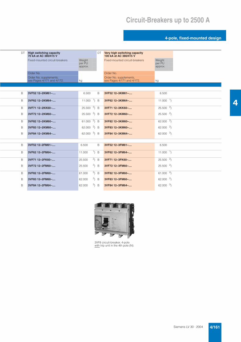
Siemens LV 30 · 2004 4/161
Circuit-Breakers up to 2500 A
4-pole, fixed-mounted design
4
DT High switching capacity 70 kA at AC 380/415 V
DT Very high switching capacity 100 kA at AC 380/415 V
Fixed-mounted circuit-breakers Weight per PU approx.
Fixed-mounted circuit-breakers Weight per PU approx.
Order No. Order No.
Order No. supplements, see Pages 4/171 and 4/172. kg
Order No. supplements, see Pages 4/171 and 4/172. kg
B 3VF52 12–2KM61–.... 6.500 B 3VF52 12–3KM61–.... 6.500
B 3VF62 12–2KM64–.... 11.000 1) B 3VF62 12–3KM64–.... 11.000 1)
B
B
3VF71 12–2KK60–....
3VF72 12–2KM60–....
25.500
25.500
2)
2)
B
B
3VF71 12–3KK60–....
3VF72 12–3KM60–....
25.500
25.500
2)
2)
B
B
B
3VF82 12–2KM60–....
3VF83 12–2KM60–....
3VF84 12–2KM64–....
61.000
62.000
62.000
2)
2)
3)
B
B
B
3VF82 12–3KM60–....
3VF83 12–3KM60–....
3VF84 12–3KM64–....
62.000
62.000
62.000
2)
2)
3)
B 3VF52 12–2FM61–.... 6.500 B 3VF52 12–3FM61–.... 6.500
B 3VF62 12–2FM64–.... 11.000 1) B 3VF62 12–3FM64–.... 11.000 1)
B
B
3VF71 12–2FK60–....
3VF72 12–2FM60–....
25.500
25.500
2)
2)
B
B
3VF71 12–3FK60–....
3VF72 12–3FM60–....
25.500
25.500
2)
2)
B
B
B
3VF82 12–2FM60–....
3VF83 12–2FM60–....
3VF84 12–2FM64–....
61.000
62.000
62.000
2)
2)
3)
B
B
B
3VF82 12–3FM60–....
3VF83 12–3FM60–....
3VF84 12–3FM64–....
61.000
62.000
62.000
2)
2)
3)
3VF8 circuit-breaker, 4-pole with trip unit in the 4th pole (N).
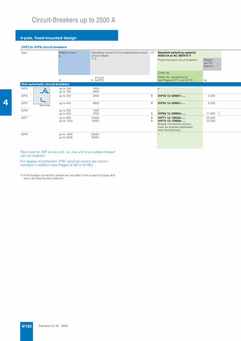
Siemens LV 30 · 20044/162
Circuit-Breakers up to 2500 A
4-pole, fixed-mounted design
4
Pack size for 3VF is one unit, i.e. one unit or a multiple thereof can be ordered.
For degree of protection IP30, terminal covers are recom-mended in addition (see Pages 4/182 to 4/185).
1) Front busbar connection pieces are included in the scope of supply and are to be fitted by the customer.
3VF3 to 3VF8 circuit-breakers
Type Rated current In
Operating current of the instantaneous short-circuit release "I" Ii
DT Standard switching capacity 40/50 kA at AC 380/415 V
Fixed-mounted circuit-breakers Weight per PU approx.
Order No.
A AOrder No. supplements, see Pages 4/171 and 4/172. kg
Non-automatic circuit-breakers3VF3 up to 100
up to 16015002400
–
3VF4 up to 250 3000 B 3VF42 12–5DM31–.... 5.500
3VF5 up to 400 4800 B 3VF52 12–5DM31–.... 6.500
3VF6 up to 500up to 630
75007500 B
–3VF62 12–5DM34–.... 11.000 1)
3VF7 up to 800up to 1250
1500015000
BB
3VF71 12–1DK30–....3VF72 12–1DM30–....Busbar connection pieces must be ordered separately (see Accessories)
25.50025.500
3VF8 up to 1600up to 2000
2000020000
–
NSE0_00708
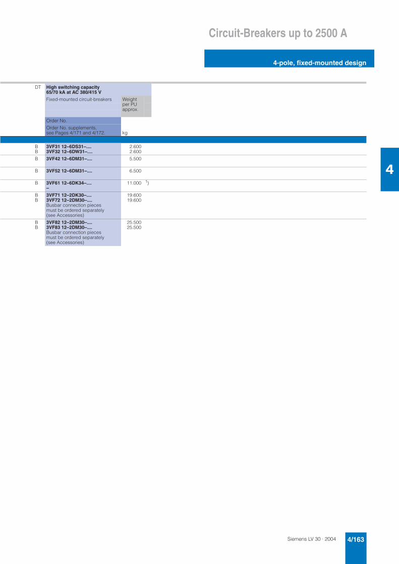
Siemens LV 30 · 2004 4/163
Circuit-Breakers up to 2500 A
4-pole, fixed-mounted design
4
DT High switching capacity 65/70 kA at AC 380/415 V
Fixed-mounted circuit-breakers Weight per PU approx.
Order No.
Order No. supplements, see Pages 4/171 and 4/172. kg
BB
3VF31 12–6DS31–....3VF32 12–6DW31–....
2.6002.600
B 3VF42 12–6DM31–.... 5.500
B 3VF52 12–6DM31–.... 6.500
B 3VF61 12–6DK34–....–
11.000 1)
BB
3VF71 12–2DK30–....3VF72 12–2DM30–....Busbar connection pieces must be ordered separately (see Accessories)
19.60019.600
BB
3VF82 12–2DM30–....3VF83 12–2DM30–....Busbar connection pieces must be ordered separately (see Accessories)
25.50025.500
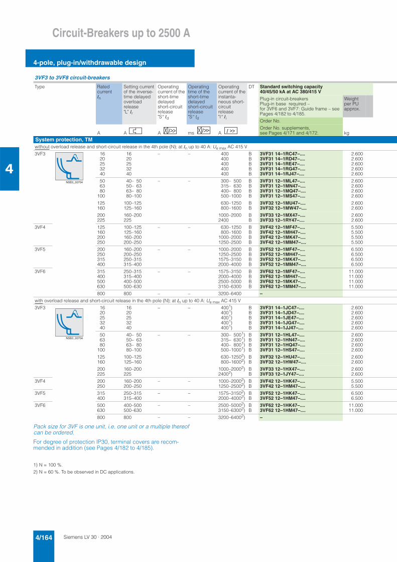
Siemens LV 30 · 20044/164
Circuit-Breakers up to 2500 A
4-pole, plug-in/withdrawable design
4
Pack size for 3VF is one unit, i.e. one unit or a multiple thereof can be ordered.
For degree of protection IP30, terminal covers are recom-mended in addition (see Pages 4/182 to 4/185).
1) N = 100 %.
2) N = 60 %. To be observed in DC applications.
3VF3 to 3VF8 circuit-breakers
Type Ratedcurrent In
Setting current of the inverse-time delayed overloadrelease "L" Ir
Operatingcurrent of the short-time delayedshort-circuit release "S" Id
Operatingtime of the short-time delayedshort-circuit release "S" td
Operatingcurrent of the instanta-neous short-circuit release "I" Ii
DT Standard switching capacity 40/45/50 kA at AC 380/415 V
Plug-in circuit-breakersPlug-in base required – for 3VF6 and 3VF7: Guide frame – see Pages 4/182 to 4/185.
Weight per PU approx.
Order No.
A A A ms AOrder No. supplements, see Pages 4/171 and 4/172. kg
System protection, TMwithout overload release and short-circuit release in the 4th pole (N); at In up to 40 A: Ue max AC 415 V
3VF3 1620253240
1620253240
– – 400400400400400
BBBBB
3VF31 14–1RC47–....3VF31 14–1RD47–....3VF31 14–1RE47–....3VF31 14–1RG47–....3VF31 14–1RJ47–....
2.6002.6002.6002.6002.600
506380
100
40– 5050– 6363– 8080–100
– – 300– 500315– 630400– 800500–1000
BBBB
3VF31 12–1ML47–....3VF31 12–1MN47–....3VF31 12–1MQ47–....3VF31 12–1MS47–....
2.6002.6002.6002.600
125160
100–125125–160
630–1250800–1600
BB
3VF32 12–1MU47–....3VF32 12–1MW47–....
2.6002.600
200225
160–200225
1000–20002400
BB
3VF33 12–1MX47–....3VF33 12–1RY47–....
2.6002.600
3VF4 125160200250
100–125125–160160–200200–250
– – 630–1250800–1600
1000–20001250–2500
BBBB
3VF42 12–1MF47–....3VF42 12–1MH47–....3VF42 12–1MK47–....3VF42 12–1MM47–....
5.5005.5005.5005.500
3VF5 200250315400
160–200200–250250–315315–400
– – 1000–20001250–25001575–31502000–4000
BBBB
3VF52 12–1MF47–....3VF52 12–1MH47–....3VF52 12–1MK47–....3VF52 12–1MM47–....
6.5006.5006.5006.500
3VF6 315400500630
250–315315–400400–500500–630
– – 1575–31502000–40002500–50003150–6300
BBBB
3VF62 12–1MF47–....3VF62 12–1MH47–....3VF62 12–1MK47–....3VF62 12–1MM47–....
11.00011.00011.00011.000
800 800 – – 3200–6400 –
with overload release and short-circuit release in the 4th pole (N); at In up to 40 A: Ue max AC 415 V
3VF3 1620253240
1620253240
– – 4001)4001)4001)4001)4001)
BBBBB
3VF31 14–1JC47–....3VF31 14–1JD47–....3VF31 14–1JE47–....3VF31 14–1JG47–....3VF31 14–1JJ47–....
2.6002.6002.6002.6002.600
506380
100
40– 5050– 6363– 8080–100
– – 300– 5001)315– 6301)400– 8001)500–10001)
BBBB
3VF31 12–1HL47–....3VF31 12–1HN47–....3VF31 12–1HQ47–....3VF31 12–1HS47–....
2.6002.6002.6002.600
125160
100–125125–160
630–12502)800–16002)
BB
3VF32 12–1HU47–....3VF32 12–1HW47–....
2.6002.600
200225
160–200225
1000–20002)24002)
BB
3VF33 12–1HX47–....3VF33 12–1JY47–....
2.6002.600
3VF4 200250
160–200200–250
– – 1000–20002)1250–25002)
BB
3VF42 12–1HK47–....3VF42 12–1HM47–....
5.5005.500
3VF5 315400
250–315315–400
– – 1575–31502)2000–40002)
BB
3VF52 12–1HK47–....3VF52 12–1HM47–....
6.5006.500
3VF6 500630
400–500500–630
– – 2500–50002)3150–63002)
BB
3VF62 12–1HK47–....3VF62 12–1HM47–....
11.00011.000
800 800 – – 3200–64002) –
NSE0_00704
NSE0_00704
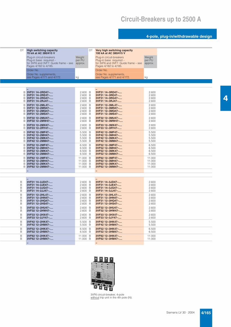
Siemens LV 30 · 2004 4/165
Circuit-Breakers up to 2500 A
4-pole, plug-in/withdrawable design
4
DT High switching capacity 70 kA at AC 380/415 V
DT Very high switching capacity 100 kA at AC 380/415 V
Plug-in circuit-breakersPlug-in base required – for 3VF6 and 3VF7: Guide frame – see Pages 4/182 to 4/185.
Weight per PU approx.
Plug-in circuit-breakersPlug-in base required – for 3VF6 and 3VF7: Guide frame – see Pages 4/182 to 4/185.
Weight per PU approx.
Order No. Order No.
Order No. supplements, see Pages 4/171 and 4/172. kg
Order No. supplements, see Pages 4/171 and 4/172. kg
BBBB
–3VF31 14–2RD47–....3VF31 14–2RE47–....3VF31 14–2RG47–....3VF31 14–2RJ47–....
2.6002.6002.6002.600
BBBB
–3VF31 14–3RD47–....3VF31 14–3RE47–....3VF31 14–3RG47–....3VF31 14–3RJ47–....
2.6002.6002.6002.600
BBBB
3VF31 12–2ML47–....3VF31 12–2MN47–....3VF31 12–2MQ47–....3VF31 12–2MS47–....
2.6002.6002.6002.600
BBBB
3VF31 12–3ML47–....3VF31 12–3MN47–....3VF31 12–3MQ47–....3VF31 12–3MS47–....
2.6002.6002.6002.600
BB
3VF32 12–2MU47–....3VF32 12–2MW47–....
2.6002.600
BB
3VF32 12–3MU47–....3VF32 12–3MW47–....
2.6002.600
BB
3VF33 12–2MX47–....3VF33 12–2RY47–....
2.6002.600
BB
3VF33 12–3MX47–....3VF33 12–3RY47–....
2.6002.600
BBBB
3VF42 12–2MF47–....3VF42 12–2MH47–....3VF42 12–2MK47–....3VF42 12–2MM47–....
5.5005.5005.5005.500
BBBB
3VF42 12–3MF47–....3VF42 12–3MH47–....3VF42 12–3MK47–....3VF42 12–3MM47–....
5.5005.5005.5005.500
BBBB
3VF52 12–2MF47–....3VF52 12–2MH47–....3VF52 12–2MK47–....3VF52 12–2MM47–....
6.5006.5006.5006.500
BBBB
3VF52 12–3MF47–....3VF52 12–3MH47–....3VF52 12–3MK47–....3VF52 12–3MM47–....
6.5006.5006.5006.500
BBBB
3VF62 12–2MF47–....3VF62 12–2MH47–....3VF62 12–2MK47–....3VF62 12–2MM47–....
11.00011.00011.00011.000
BBBB
3VF62 12–3MF47–....3VF62 12–3MH47–....3VF62 12–3MK47–....3VF62 12–3MM47–....
11.00011.00011.00011.000
– –
BBBB
–3VF31 14–2JD47–....3VF31 14–2JE47–....3VF31 14–2JG47–....3VF31 14–2JJ47–....
2.6002.6002.6002.600
BBBB
–3VF31 14–3JD47–....3VF31 14–3JE47–....3VF31 14–3JG47–....3VF31 14–3JJ47–....
2.6002.6002.6002.600
BBBB
3VF31 12–2HL47–....3VF31 12–2HN47–....3VF31 12–2HQ47–....3VF31 12–2HS47–....
2.6002.6002.6002.600
BBBB
3VF31 12–3HL47–....3VF31 12–3HN47–....3VF31 12–3HQ47–....3VF31 12–3HS47–....
2.6002.6002.6002.600
BB
3VF32 12–2HU47–....3VF32 12–2HW47–....
2.6002.600
BB
3VF32 12–3HU47–....3VF32 12–3HW47–....
2.6002.600
BB
3VF33 12–2HX47–....3VF33 12–2JY47–....
2.6002.600
BB
3VF33 12–3HX47–....3VF33 12–3JY47–....
2.6002.600
BB
3VF42 12–2HK47–....3VF42 12–2HM47–....
5.5005.500
BB
3VF42 12–3HK47–....3VF42 12–3HM47–....
5.5005.500
BB
3VF52 12–2HK47–....3VF52 12–2HM47–....
6.5006.500
BB
3VF52 12–3HK47–....3VF52 12–3HM47–....
6.5006.500
BB
3VF62 12–2HK47–....3VF62 12–2HM47–....
11.00011.000
BB
3VF62 12–3HK47–....3VF62 12–3HM47–....
11.00011.000
– –
3VF6 circuit-breaker, 4-pole without trip unit in the 4th pole (N).
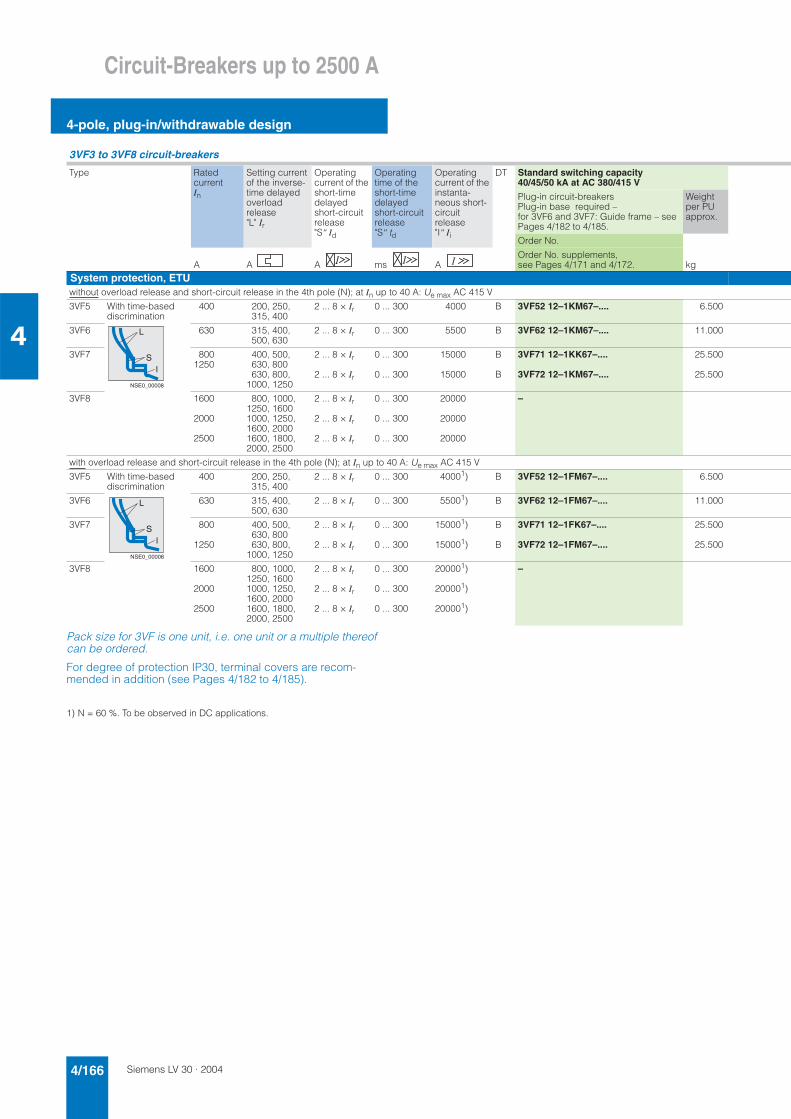
Siemens LV 30 · 20044/166
Circuit-Breakers up to 2500 A
4-pole, plug-in/withdrawable design
4
Pack size for 3VF is one unit, i.e. one unit or a multiple thereof can be ordered.
For degree of protection IP30, terminal covers are recom-mended in addition (see Pages 4/182 to 4/185).
1) N = 60 %. To be observed in DC applications.
3VF3 to 3VF8 circuit-breakers
Type Ratedcurrent In
Setting current of the inverse-time delayed overloadrelease "L" Ir
Operatingcurrent of the short-time delayedshort-circuit release "S" Id
Operatingtime of the short-time delayedshort-circuit release "S" td
Operatingcurrent of the instanta-neous short-circuit release "I" Ii
DT Standard switching capacity 40/45/50 kA at AC 380/415 V
Plug-in circuit-breakersPlug-in base required – for 3VF6 and 3VF7: Guide frame – see Pages 4/182 to 4/185.
Weight per PU approx.
Order No.
A A A ms AOrder No. supplements, see Pages 4/171 and 4/172. kg
System protection, ETUwithout overload release and short-circuit release in the 4th pole (N); at In up to 40 A: Ue max AC 415 V
3VF5 With time-based discrimination
400 200, 250, 315, 400
2 ... 8 × Ir 0 ... 300 4000 B 3VF52 12–1KM67–.... 6.500
3VF6 630 315, 400, 500, 630
2 ... 8 × Ir 0 ... 300 5500 B 3VF62 12–1KM67–.... 11.000
3VF7 8001250
400, 500, 630, 800630, 800,
1000, 1250
2 ... 8 × Ir
2 ... 8 × Ir
0 ... 300
0 ... 300
15000
15000
B
B
3VF71 12–1KK67–....
3VF72 12–1KM67–....
25.500
25.500
3VF8 1600
2000
2500
800, 1000, 1250, 16001000, 1250, 1600, 20001600, 1800, 2000, 2500
2 ... 8 × Ir
2 ... 8 × Ir
2 ... 8 × Ir
0 ... 300
0 ... 300
0 ... 300
20000
20000
20000
–
with overload release and short-circuit release in the 4th pole (N); at In up to 40 A: Ue max AC 415 V
3VF5 With time-based discrimination
400 200, 250, 315, 400
2 ... 8 × Ir 0 ... 300 40001) B 3VF52 12–1FM67–.... 6.500
3VF6 630 315, 400, 500, 630
2 ... 8 × Ir 0 ... 300 55001) B 3VF62 12–1FM67–.... 11.000
3VF7 800
1250
400, 500, 630, 800630, 800,
1000, 1250
2 ... 8 × Ir
2 ... 8 × Ir
0 ... 300
0 ... 300
150001)
150001)
B
B
3VF71 12–1FK67–....
3VF72 12–1FM67–....
25.500
25.500
3VF8 1600
2000
2500
800, 1000, 1250, 16001000, 1250, 1600, 20001600, 1800, 2000, 2500
2 ... 8 × Ir
2 ... 8 × Ir
2 ... 8 × Ir
0 ... 300
0 ... 300
0 ... 300
200001)
200001)
200001)
–
L
SI
NSE0_00008
L
SI
NSE0_00008
Siemens LV 30 · 2004 4/167
Circuit-Breakers up to 2500 A
4-pole, plug-in/withdrawable design
4
DT High switching capacity 70 kA at AC 380/415 V
DT Very high switching capacity 100 kA at AC 380/415 V
Plug-in circuit-breakersPlug-in base required – for 3VF6 and 3VF7: Guide frame – see Pages 4/182 to 4/185.
Weight per PU approx.
Plug-in circuit-breakersPlug-in base required – for 3VF6 and 3VF7: Guide frame – see Pages 4/182 to 4/185.
Weight per PU approx.
Order No. Order No.
Order No. supplements, see Pages 4/171 and 4/172. kg
Order No. supplements, see Pages 4/171 and 4/172. kg
B 3VF52 12–2KM67–.... 6.500 B 3VF52 12–3KM67–.... 6.500
B 3VF62 12–2KM67–.... 11.000 B 3VF62 12–3KM67–.... 11.000
B
B
3VF71 12–2KK67–....
3VF72 12–2KM67–....
25.500
25.500
B
B
3VF71 12–3KK67–....
3VF72 12–3KM67–....
25.500
25.500
– –
B 3VF52 12–2FM67–.... 6.500 B 3VF52 12–3FM67–.... 6.500
B 3VF62 12–2FM67–.... 11.000 B 3VF62 12–3FM67–.... 11.000
B
B
3VF71 12–2FK67–....
3VF72 12–2FM67–....
25.500
25.500
B
B
3VF71 12–3FK67–....
3VF72 12–3FM67–....
25.500
25.500
– –
3VF8 circuit-breaker, 4-pole with trip unit in the 4th pole (N).
Siemens LV 30 · 20044/168
Circuit-Breakers up to 2500 A
4-pole, plug-in/withdrawable design
4
Pack size for 3VF is one unit, i.e. one unit or a multiple thereof can be ordered.
For degree of protection IP30, terminal covers are recom-mended in addition (see Pages 4/182 to 4/185).
3VF3 to 3VF8 circuit-breakers
Type Rated current In
Operating current of the instantaneous short-circuit release "I" Ii
DT Standard switching capacity 40/50 kA at AC 380/415 V
Plug-in circuit-breakersPlug-in base required – for 3VF6 and 3VF7: Guide frame – see Pages 4/182 to 4/185.
Weight per PU approx.
Order No.
A AOrder No. supplements, see Pages 4/171 and 4/172. kg
Non-automatic circuit-breakers3VF3 up to 100
up to 16015002400
–
3VF4 up to 250 3000 B 3VF42 12–5DM37–.... 5.500
3VF5 up to 400 4800 B 3VF52 12–5DM37–.... 6.500
3VF6 up to 500up to 630
75007500 B
–3VF62 12–5DM37–.... 11.000
3VF7 up to 800up to 1250
1500015000
BB
3VF71 12–1DK37–....3VF72 12–1DM37–....
25.50025.500
3VF8 up to 1600up to 2000
2000020000
–
NSE0_00708
Siemens LV 30 · 2004 4/169
Circuit-Breakers up to 2500 A
4-pole, plug-in/withdrawable design
4
DT High switching capacity 65/70 kA at AC 380/415 V
Plug-in circuit-breakersPlug-in base required – for 3VF6 and 3VF7: Guide frame – see Pages 4/182 to 4/185.
Weight per PU approx.
Order No.
Order No. supplements, see Pages 4/171 and 4/172. kg
BB
3VF31 12–6DS37–....3VF32 12–6DW37–....
2.6002.600
B 3VF42 12–6DM37–.... 5.500
B 3VF52 12–6DM37–.... 6.500
B 3VF61 12–6DK37–....–
11.000
BB
3VF71 12–2DK37–....3VF72 12–2DM37–....
19.60019.600
–
Siemens LV 30 · 20044/170
Circuit-Breakers up to 2500 A
3-pole, fixed-mounted design
General Use Switch
4
Approved according to IEC 60947-2, UL 508 and CSA C22.2, No. 141)/circuit-breakers according to UL 489 on request 3VF3 to 3VF6 circuit-breakers
1) Only operated with back-up fuses approved according to UL or CSA (see Page 4/139) up to AC 600 V.
2) With box terminals: on 3VF3 for Cu cables AWG 14–2/0 (25 to 50 mm2);on 3VF4 for Cu/Al cables AWG 4–350 MCM (25 to 185 mm2);on 3VF5 and 3VF6 for Cu/Al cables MCM 250–350 (120 to 150 mm2)(on 3VF6 for 2 cables).
3) Accessories with connecting leads required.
Type Ratedcurrent In
Operating current of the instan-taneousshort-cir-cuit release "I" Ii
DT Standard switching capacity DT High switching capacity DT Very high switching capacity
Fixed-mounted circuit-breakers
Weight per PU approx.
Fixed-mounted circuit-breakers
Weight per PU approx.
Fixed-mounted circuit-breakers
Weight per PU approx.with box terminals2) with box terminals2) with box terminals2)
Order No. Order No. Order No.
A A
Order No. supplements, see Pages 4/171 and 4/1723). kg
Order No. supplements, see Pages 4/171 and 4/1723). kg
Order No. supplements, see Pages 4/171 and 4/1723). kg
Circuit-breakers for system protectionwith permanently set overload/short-circuit releases
Short-circuit breaking capacity (NEMA rating): 25 kA with AC 480 V 18 kA with AC 600 V
Short-circuit breaking capacity (NEMA rating): 65 kA with AC 480 V 25 kA with AC 600 V
Short-circuit breaking capacity (NEMA rating): 100 kA with AC 480 V 35 kA with AC 600 V
3VF3 506080
100
400500630800
BBBB
3VF31 31–1FL41–....3VF31 31–1FN41–....3VF31 31–1FQ41–....3VF31 31–1FS41–....
2.3002.3002.3002.300
BBBB
3VF31 31–2FL41–....3VF31 31–2FN41–....3VF31 31–2FQ41–....3VF31 31–2FS41–....
2.3002.3002.3002.300
BBBB
3VF31 31–3FL41–....3VF31 31–3FN41–....3VF31 31–3FQ41–....3VF31 31–3FS41–....
2.3002.3002.3002.300
with permanently set thermal overload releases and adjustable instantaneous short-circuit releases
Short-circuit breaking capacity (NEMA rating): 25 kA with AC 480 V 18 kA with AC 600 V
Short-circuit breaking capacity (NEMA rating): 65 kA with AC 480 V 25 kA with AC 600 V
Short-circuit breaking capacity (NEMA rating): 100 kA with AC 480 V 50 kA with AC 600 V
3VF4 125150200250
625–1250800–1600
1000–20001250–2500
BBBB
3VF42 31–1DF41–....3VF42 31–1DH41–....3VF42 31–1DK41–....3VF42 31–1DM41–....
4.2004.2004.2004.200
BBBB
3VF42 31–2DF41–....3VF42 31–2DH41–....3VF42 31–2DK41–....3VF42 31–2DM41–....
4.2004.2004.2004.200
BBBB
3VF42 31–3DF41–....3VF42 31–3DH41–....3VF42 31–3DK41–....3VF42 31–3DM41–....
4.2004.2004.2004.200
Short-circuit breaking capacity (NEMA rating): 35 kA with AC 480 V 25 kA with AC 600 V
Short-circuit breaking capacity (NEMA rating): 65 kA with AC 480 V 35 kA with AC 600 V
Short-circuit breaking capacity (NEMA rating): 100 kA with AC 480 V 50 kA with AC 600 V
3VF5 200250
1000–20001250–2500
BB
3VF52 31–1DF41–....3VF52 31–1DH41–....
5.5005.500
BB
3VF52 31–2DF41–....3VF52 31–2DH41–....
5.5005.500
BB
3VF52 31–3DF41–....3VF52 31–3DH41–....
5.5005.500
Short-circuit breaking capacity (NEMA rating): 35 kA with AC 480 V 25 kA with AC 600 V
Short-circuit breaking capacity (NEMA rating): 65 kA with AC 480 V 35 kA with AC 600 V
Short-circuit breaking capacity (NEMA rating): 100 kA with AC 480 V 50 kA with AC 600 V
3VF6 300400500
1575–31502000–40002500–5000
BBB
3VF62 31–1DF41–....3VF62 31–1DH41–....3VF62 31–1DK41–....
8.4008.4008.400
BBB
3VF62 31–2DF41–....3VF62 31–2DH41–....3VF62 31–2DK41–....
8.4008.4008.400
BBB
3VF62 31–3DF41–....3VF62 31–3DH41–....3VF62 31–3DK41–....
8.4008.4008.400
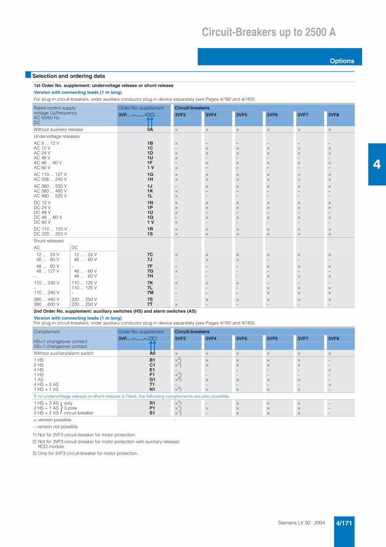
Siemens LV 30 · 2004 4/171
Circuit-Breakers up to 2500 A
Options
4
■ Selection and ordering data
1) Not for 3VF3 circuit-breaker for motor protection.
2) Not for 3VF3 circuit-breaker for motor protection with auxiliary release/RCD module.
3) Only for 3VF3 circuit-breaker for motor protection.
1st Order No. supplement: undervoltage release or shunt release
Version with connecting leads (1 m long)
For plug-in circuit-breakers, order auxiliary conductor plug-in device separately (see Pages 4/182 and 4/183).
Rated control supply voltage US/frequency AC 50/60 Hz DC
Order No. supplement Circuit-breakers
3VF.. ..–.....–@@. . 3VF3 3VF4 3VF5 3VF6 3VF7 3VF8
Without auxiliary release 0A × × × × × ×
Undervoltage releases
AC 9 ... 12 VAC 12 VAC 24 VAC 48 VAC 48 ... 60 VAC 60 V
AC 110 ... 127 VAC 208 ... 240 V
AC 380 ... 500 VAC 380 ... 480 VAC 480 ... 525 V
DC 12 VDC 24 VDC 48 VDC 48 ... 60 VDC 60 V
DC 110 ... 125 VDC 220 ... 250 V
1B1C1D1U1F1 V
1G1H
1J1K1L
1N1P1U1Q1 V
1R1S
×–××–×
××
–××
×××–×
××
–××–×–
××
×––
××–×–
××
–××–×–
××
×––
××–×–
××
–××–×–
××
×––
××–×–
××
–××–×–
××
×––
××–×–
××
–××–×–
××
×––
××–×–
××
Shunt releases
AC DC
12 ... 24 V48 ... 60 V
48 ... 60 V48 ... 127 V
–
110 ... 240 V–110 ... 240 V
380 ... 440 V380 ... 600 V
12 ... 24 V48 ... 60 V
–48 ... 60 V48 ... 60 V
110 ... 125 V110 ... 125 V–
220 ... 250 V220 ... 250 V
7C7J
7F7G7H
7K7L7M
7S7T
×–
–×–
×––
–×
××
–––
×––
×–
××
–––
×––
×–
×–
×–×
–××
×–
×–
×–×
–××
×–
×–
×–×
–××
×–
2nd Order No. supplement: auxiliary switches (HS) and alarm switches (AS)
Version with connecting leads (1 m long)For plug-in circuit-breakers, order auxiliary conductor plug-in device separately (see Pages 4/182 and 4/183).
Complement
HS=1 changeover contactAS=1 changeover contact
Order No. supplement Circuit-breakers
3VF.. ..–.....–..@@ 3VF3 3VF4 3VF5 3VF6 3VF7 3VF8
Without auxiliary/alarm switch A0 × × × × × ×
1 HS2 HS4 HS1 HS1 AS4 HS + 2 AS1 HS + 1 AS
B1C1E1F1G1T1N1
×2)×2)–×3)×2)–×2)
××––×–×
××––×–×
××––×–×
××––×–×
––×––×–
If no undervoltage release or shunt release is fitted, the following complements are also possible:
1 HS + 2 AS only2 HS + 1 AS 3-pole2 HS + 2 AS circuit-breaker
R1P1S1
×1)×1)×1)
–×–
×××
×××
×××
–––
× version possible.
– version not possible
.
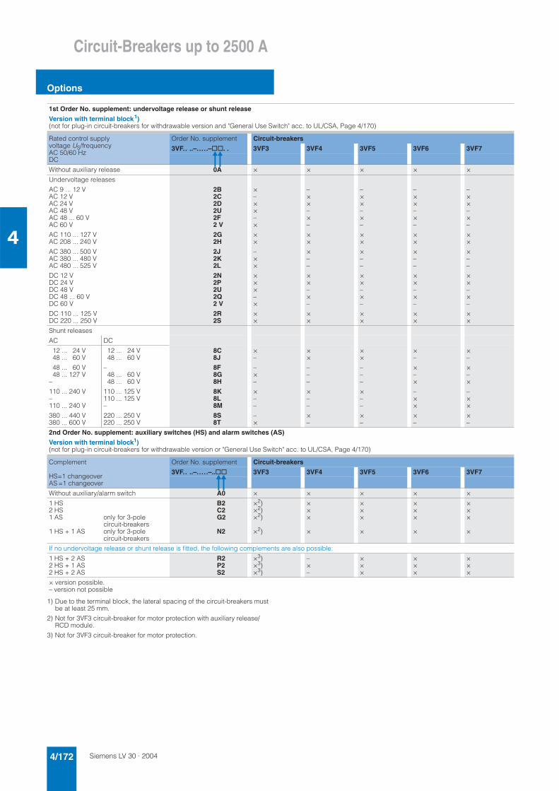
Siemens LV 30 · 20044/172
Circuit-Breakers up to 2500 A
Options
4
1) Due to the terminal block, the lateral spacing of the circuit-breakers must be at least 25 mm.
2) Not for 3VF3 circuit-breaker for motor protection with auxiliary release/RCD module.
3) Not for 3VF3 circuit-breaker for motor protection.
1st Order No. supplement: undervoltage release or shunt release
Version with terminal block1)(not for plug-in circuit-breakers for withdrawable version and "General Use Switch" acc. to UL/CSA, Page 4/170)
Rated control supply voltage US/frequency AC 50/60 Hz DC
Order No. supplement Circuit-breakers
3VF.. ..–.....–@@. . 3VF3 3VF4 3VF5 3VF6 3VF7
Without auxiliary release 0A × × × × ×
Undervoltage releases
AC 9 ... 12 VAC 12 VAC 24 VAC 48 VAC 48 ... 60 VAC 60 V
AC 110 ... 127 VAC 208 ... 240 V
AC 380 ... 500 VAC 380 ... 480 VAC 480 ... 525 V
DC 12 VDC 24 VDC 48 VDC 48 ... 60 VDC 60 V
DC 110 ... 125 VDC 220 ... 250 V
2B2C2D2U2F2 V
2G2H
2J2K2L
2N2P2U2Q2 V
2R2S
×–××–×
××
–××
×××–×
××
–××–×–
××
×––
××–×–
××
–××–×–
××
×––
××–×–
××
–××–×–
××
×––
××–×–
××
–××–×–
××
×––
××–×–
××
Shunt releases
AC DC
12 ... 24 V48 ... 60 V
48 ... 60 V48 ... 127 V
–
110 ... 240 V–110 ... 240 V
380 ... 440 V380 ... 600 V
12 ... 24 V48 ... 60 V
–48 ... 60 V48 ... 60 V
110 ... 125 V110 ... 125 V–
220 ... 250 V220 ... 250 V
8C8J
8F8G8H
8K8L8M
8S8T
×–
–×–
×––
–×
××
–––
×––
×–
××
–––
×––
×–
×–
×–×
–××
×–
×–
×–×
–××
×–
2nd Order No. supplement: auxiliary switches (HS) and alarm switches (AS)
Version with terminal block1)(not for plug-in circuit-breakers for withdrawable version or "General Use Switch" acc. to UL/CSA, Page 4/170)
Complement
HS=1 changeoverAS =1 changeover
Order No. supplement Circuit-breakers
3VF.. ..–.....–..@@ 3VF3 3VF4 3VF5 3VF6 3VF7
Without auxiliary/alarm switch A0 × × × × ×
1 HS2 HS1 AS
1 HS + 1 AS
only for 3-pole circuit-breakersonly for 3-pole circuit-breakers
B2C2G2
N2
×2)×2)×2)
×2)
×××
×
×××
×
×××
×
×××
×
If no undervoltage release or shunt release is fitted, the following complements are also possible:
1 HS + 2 AS2 HS + 1 AS2 HS + 2 AS
R2P2S2
×3)×3)×3)
–×–
×××
×××
×××
× version possible.– version not possible
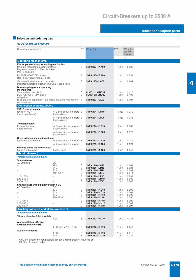
Siemens LV 30 · 2004 4/173
Circuit-Breakers up to 2500 A
Accessories/spare parts
4
■ Selection and ordering data
for 3VF2 circuit-breakers
1) Only one accessory part possible per 3VF2 circuit-breaker; mounting on left side of circuit-breaker.
Operating mechanisms DT Order No. PS* Weight per PU approx.
kgOperating mechanismsFront-operated rotary operating mechanismfor direct mounting on circuit-breakers B 3VF9 223–1AA00 1 unit 0.232Degree of protection IP30, black knobMax. 3 padlocks
EMERGENCY-STOP version B 3VF9 223–1BA00 1 unit 0.232Red knob, yellow indicator plate
Version with shaft stub without knob (required operating mechanism 8UC61, see below)
B 3VF9 223–1JA00 1 unit 0.204
Door-coupling rotary operating mechanismsStandard version, black B 8UC61 12–1BD22 1 unit 0.417EMERGENCY-STOP version, red/yellow
B 8UC61 22–3BD22 1 unit 0.402
to be ordered separately: front rotary operating mechanism with shaft stub
B 3VF9 223–1JA00 1 unit 0.204
Connection systems, covers3VF22 rear terminalsfor 45 to 100 A (cover, see below)
for 3-pole circuit-breakers 1 set = 6 units
B 3VF9 224–1LD10 1 set 0,252
for 4-pole circuit-breakers 1 set = 8 units
B 3VF9 224–1LD20 1 set 0.333
Terminal coversfor main terminal, cable terminal
for 3-pole circuit-breakers 1 set = 2 units
B 3VF9 224–1NB10 1 set 0.063
for 4-pole circuit-breakers 1 set = 2 units
B 3VF9 224–1NB20 1 set 0.079
Cover with cap dimension 45 mmfor distributor structure for 3-pole circuit-breakers B 3VF9 220–1CA10 1 unit 0.019
for 4-pole circuit-breakers B 3VF9 220–1CA20 1 unit 0.021
Masking frame for door cut-outFor circuit-breakers 1 set = 1 unit B 3VF9 220–1AA00 1 set 0.048Shunt releases1)Version with terminal blockShunt releaseAC 50/60 Hz DC– 12 V B 3VF9 221–1JC10 1 unit 0.282– 24 V B 3VF9 221–1JD10 1 unit 0.281– 48 V B 3VF9 221–1JH10 1 unit 0.289– 110–125 V B 3VF9 221–1JL10 1 unit 0.271
110–127 V – B 3VF9 221–1JP10 1 unit 0.292220–240 V – B 3VF9 221–1JM10 1 unit 0.280380–415 V – B 3VF9 221–1JV10 1 unit 0.282
Shunt release with auxiliary switch 1 COAC 50/60 Hz DC– 12 V B 3VF9 221–1KC10 1 unit 0.298– 24 V B 3VF9 221–1KD10 1 unit 0.302– 48 V B 3VF9 221–1KH10 1 unit 0.303– 110–125 V B 3VF9 221–1KL10 1 unit 0.296
110–127 V – B 3VF9 221–1KP10 1 unit 0.300220–240 V – B 3VF9 221–1KM10 1 unit 0.302380-415 V – B 3VF9 221–1KV10 1 unit 0.297Auxiliary switches and alarm switches1)Version with terminal blockTripped signaling/alarm switch
1 CO B 3VF9 222–1AC10 1 unit 0.233
Alarm switches (AS) and auxiliary switches (HS)
1 CO (AS) + 1 CO (HS) B 3VF9 222–1DC10 1 unit 0.243
Auxiliary switches1 CO B 3VF9 222–1BC10 1 unit 0.2152 CO B 3VF9 222–1CC10 1 unit 0.235
* This quantity or a multiple thereof quantity can be ordered.
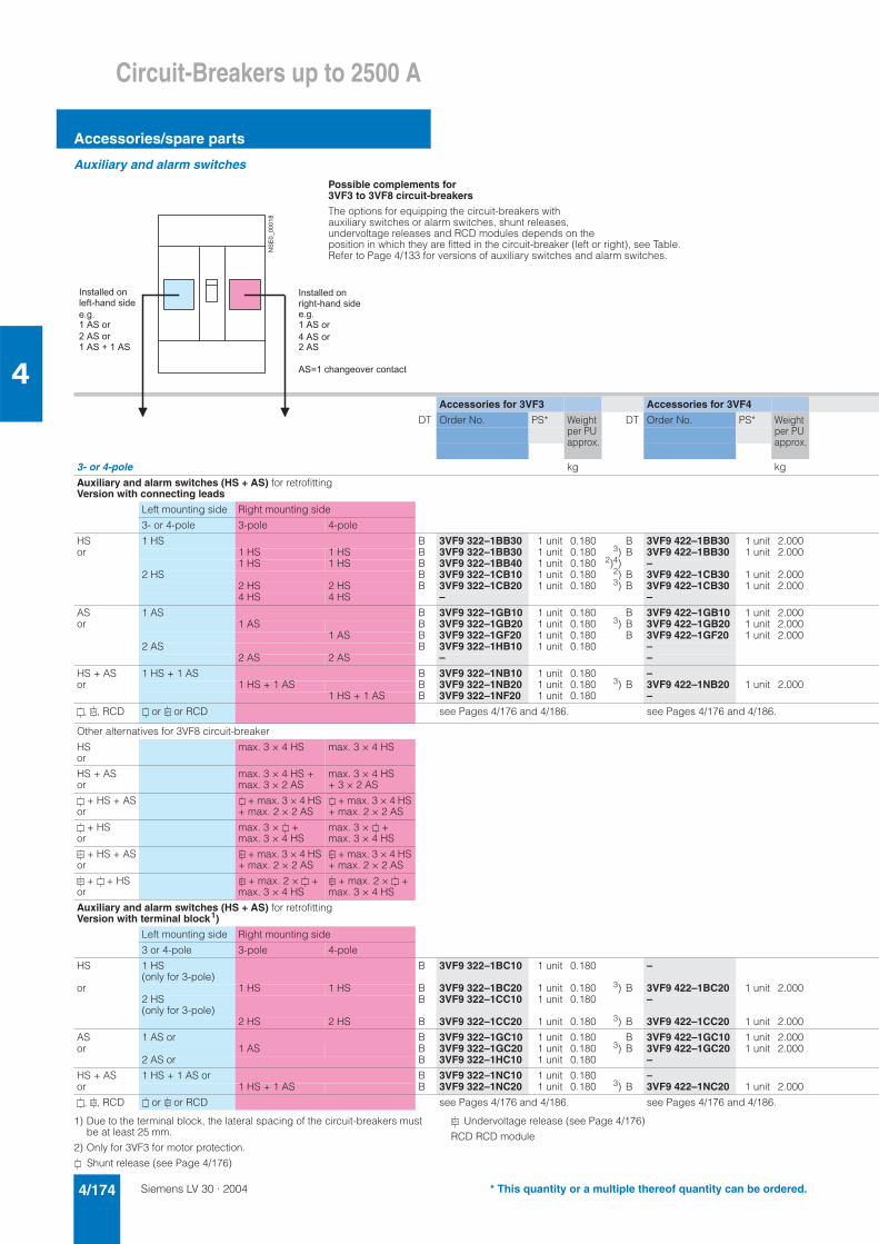
Siemens LV 30 · 20044/174
Circuit-Breakers up to 2500 A
Accessories/spare parts
4
Auxiliary and alarm switches
1) Due to the terminal block, the lateral spacing of the circuit-breakers must be at least 25 mm.
2) Only for 3VF3 for motor protection.
Shunt release (see Page 4/176)
Undervoltage release (see Page 4/176)
RCD RCD module
Possible complements for 3VF3 to 3VF8 circuit-breakers
The options for equipping the circuit-breakers with auxiliary switches or alarm switches, shunt releases, undervoltage releases and RCD modules depends on the position in which they are fitted in the circuit-breaker (left or right), see Table. Refer to Page 4/133 for versions of auxiliary switches and alarm switches.
Accessories for 3VF3 Accessories for 3VF4
DT Order No. PS* Weight per PU approx.
DT Order No. PS* Weight per PU approx.
3- or 4-pole kg kg
Auxiliary and alarm switches (HS + AS) for retrofittingVersion with connecting leads
Left mounting side Right mounting side
3- or 4-pole 3-pole 4-pole
HS 1 HS B 3VF9 322–1BB30 1 unit 0.180 B 3VF9 422–1BB30 1 unit 2.000or 1 HS 1 HS B 3VF9 322–1BB30 1 unit 0.180 3) B 3VF9 422–1BB30 1 unit 2.000
1 HS 1 HS B 3VF9 322–1BB40 1 unit 0.180 2)4) –2 HS B 3VF9 322–1CB10 1 unit 0.180 2) B 3VF9 422–1CB30 1 unit 2.000
2 HS 2 HS B 3VF9 322–1CB20 1 unit 0.180 3) B 3VF9 422–1CB30 1 unit 2.0004 HS 4 HS – –
AS 1 AS B 3VF9 322–1GB10 1 unit 0.180 B 3VF9 422–1GB10 1 unit 2.000or 1 AS B 3VF9 322–1GB20 1 unit 0.180 3) B 3VF9 422–1GB20 1 unit 2.000
1 AS B 3VF9 322–1GF20 1 unit 0.180 B 3VF9 422–1GF20 1 unit 2.0002 AS B 3VF9 322–1HB10 1 unit 0.180 –
2 AS 2 AS – –
HS + AS 1 HS + 1 AS B 3VF9 322–1NB10 1 unit 0.180 –or 1 HS + 1 AS B 3VF9 322–1NB20 1 unit 0.180 3) B 3VF9 422–1NB20 1 unit 2.000
1 HS + 1 AS B 3VF9 322–1NF20 1 unit 0.180 –
, , RCD or or RCD see Pages 4/176 and 4/186. see Pages 4/176 and 4/186.
Other alternatives for 3VF8 circuit-breaker
HSor
max. 3 × 4 HS max. 3 × 4 HS
HS + ASor
max. 3 × 4 HS + max. 3 × 2 AS
max. 3 × 4 HS + 3 × 2 AS
+ HS + ASor
+ max. 3 × 4 HS + max. 2 × 2 AS
+ max. 3 × 4 HS + max. 2 × 2 AS
+ HSor
max. 3 × + max. 3 × 4 HS
max. 3 × + max. 3 × 4 HS
+ HS + ASor
+ max. 3 × 4 HS + max. 2 × 2 AS
+ max. 3 × 4 HS + max. 2 × 2 AS
+ + HSor
+ max. 2 × + max. 3 × 4 HS
+ max. 2 × + max. 3 × 4 HS
Auxiliary and alarm switches (HS + AS) for retrofittingVersion with terminal block1)
Left mounting side Right mounting side
3 or 4-pole 3-pole 4-pole
HS 1 HS (only for 3-pole)
B 3VF9 322–1BC10 1 unit 0.180 –
or 1 HS 1 HS B 3VF9 322–1BC20 1 unit 0.180 3) B 3VF9 422–1BC20 1 unit 2.0002 HS (only for 3-pole)
B 3VF9 322–1CC10 1 unit 0.180 –
2 HS 2 HS B 3VF9 322–1CC20 1 unit 0.180 3) B 3VF9 422–1CC20 1 unit 2.000
AS 1 AS or B 3VF9 322–1GC10 1 unit 0.180 B 3VF9 422–1GC10 1 unit 2.000or 1 AS B 3VF9 322–1GC20 1 unit 0.180 3) B 3VF9 422–1GC20 1 unit 2.000
2 AS or B 3VF9 322–1HC10 1 unit 0.180 –
HS + AS 1 HS + 1 AS or B 3VF9 322–1NC10 1 unit 0.180 –or 1 HS + 1 AS B 3VF9 322–1NC20 1 unit 0.180 3) B 3VF9 422–1NC20 1 unit 2.000
, , RCD or or RCD see Pages 4/176 and 4/186. see Pages 4/176 and 4/186.
��������7
4 � � � � � � � ! � � �
� � ( � 8 � � � ! � � � ! �
� : � :
� � � � � �
� � � � � � �
� � � � 0 � � � �
4 � � � � � � � ! � � � �
� � � � � 8 � � � ! � � � ! �
� : � :
� � � � � �
� � � � � �
� � � �
� � @ � � � � � � � � � � � � � � � �
A A
A A A
A A A
A A
A
* This quantity or a multiple thereof quantity can be ordered.
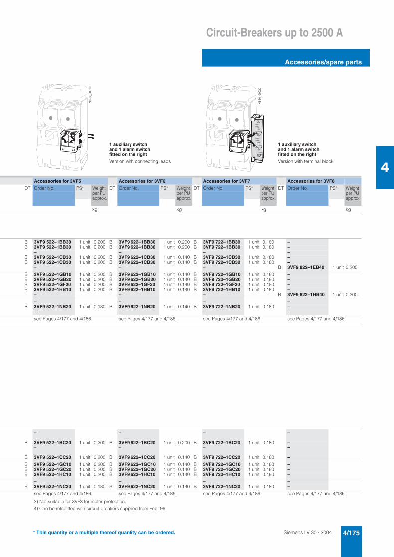
Siemens LV 30 · 2004 4/175
Circuit-Breakers up to 2500 A
Accessories/spare parts
4
1 auxiliary switch and 1 alarm switch fitted on the right
Version with connecting leads
1 auxiliary switch and 1 alarm switch fitted on the right
Version with terminal block
Accessories for 3VF5 Accessories for 3VF6 Accessories for 3VF7 Accessories for 3VF8
DT Order No. PS* Weight per PU approx.
DT Order No. PS* Weight per PU approx.
DT Order No. PS* Weight per PU approx.
DT Order No. PS* Weight per PU approx.
kg kg kg kg
B 3VF9 522–1BB30 1 unit 0.200 B 3VF9 622–1BB30 1 unit 0.200 B 3VF9 722–1BB30 1 unit 0.180 –B 3VF9 522–1BB30 1 unit 0.200 B 3VF9 622–1BB30 1 unit 0.200 B 3VF9 722–1BB30 1 unit 0.180 –
– – – –B 3VF9 522–1CB30 1 unit 0.200 B 3VF9 622–1CB30 1 unit 0.140 B 3VF9 722–1CB30 1 unit 0.180 –B 3VF9 522–1CB30 1 unit 0.200 B 3VF9 622–1CB30 1 unit 0.140 B 3VF9 722–1CB30 1 unit 0.180 –
– – – B 3VF9 822–1EB40 1 unit 0.200
B 3VF9 522–1GB10 1 unit 0.200 B 3VF9 622–1GB10 1 unit 0.140 B 3VF9 722–1GB10 1 unit 0.180 –B 3VF9 522–1GB20 1 unit 0.200 B 3VF9 622–1GB20 1 unit 0.140 B 3VF9 722–1GB20 1 unit 0.180 –B 3VF9 522–1GF20 1 unit 0.200 B 3VF9 622–1GF20 1 unit 0.140 B 3VF9 722–1GF20 1 unit 0.180 –B 3VF9 522–1HB10 1 unit 0.200 B 3VF9 622–1HB10 1 unit 0.140 B 3VF9 722–1HB10 1 unit 0.180 –
– – – B 3VF9 822–1HB40 1 unit 0.200
– – – –B 3VF9 522–1NB20 1 unit 0.180 B 3VF9 622–1NB20 1 unit 0.140 B 3VF9 722–1NB20 1 unit 0.180 –
– – – –
see Pages 4/177 and 4/186. see Pages 4/177 and 4/186. see Pages 4/177 and 4/186. see Pages 4/177 and 4/186.
– – – –
B 3VF9 522–1BC20 1 unit 0.200 B 3VF9 622–1BC20 1 unit 0.200 B 3VF9 722–1BC20 1 unit 0.180 –– – – –
B 3VF9 522–1CC20 1 unit 0.200 B 3VF9 622–1CC20 1 unit 0.140 B 3VF9 722–1CC20 1 unit 0.180 –
B 3VF9 522–1GC10 1 unit 0.200 B 3VF9 622–1GC10 1 unit 0.140 B 3VF9 722–1GC10 1 unit 0.180 –B 3VF9 522–1GC20 1 unit 0.200 B 3VF9 622–1GC20 1 unit 0.140 B 3VF9 722–1GC20 1 unit 0.180 –B 3VF9 522–1HC10 1 unit 0.200 B 3VF9 622–1HC10 1 unit 0.140 B 3VF9 722–1HC10 1 unit 0.180 –
– – – –B 3VF9 522–1NC20 1 unit 0.180 B 3VF9 622–1NC20 1 unit 0.140 B 3VF9 722–1NC20 1 unit 0.180 –
see Pages 4/177 and 4/186. see Pages 4/177 and 4/186. see Pages 4/177 and 4/186. see Pages 4/177 and 4/186.
3) Not suitable for 3VF3 for motor protection.
4) Can be retrofitted with circuit-breakers supplied from Feb. 96.
���!&
!!!�
$
���!&
!!!�
!
* This quantity or a multiple thereof quantity can be ordered.
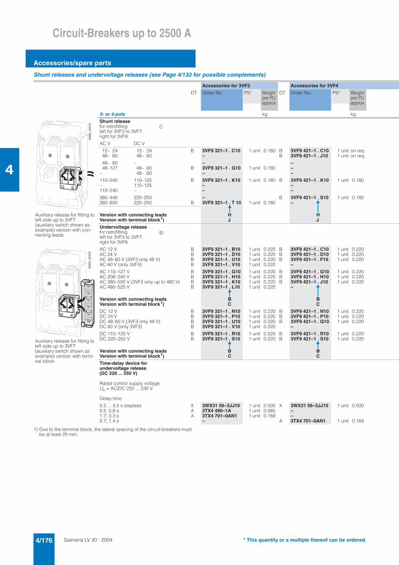
Siemens LV 30 · 20044/176
Circuit-Breakers up to 2500 A
Accessories/spare parts
4
Shunt releases and undervoltage releases (see Page 4/133 for possible complements)
1) Due to the terminal block, the lateral spacing of the circuit-breakers must be at least 25 mm.
Accessories for 3VF3 Accessories for 3VF4
DT Order No. PS* Weight per PU approx.
DT Order No. PS* Weight per PU approx.
3- or 4-pole kg kg
Shunt releasefor retrofitting left for 3VF3 to 3VF7, right for 3VF8
AC V DC V
12– 24 12– 24 B 3VF9 321–1 . C10 1 unit 0.180 B 3VF9 421–1 . C10 1 unit on req.48– 60 48– 60 – B 3VF9 421–1 . J10 1 unit on req.
48– 60 – – –48–127 48– 60 B 3VF9 321–1 . G10 1 unit 0.180 –
– 48– 60 – –
110–240 110–125 B 3VF9 321–1 . K10 1 unit 0.180 B 3VF9 421–1 . K10 1 unit 0.180– 110–125 – –110–240 – – –
380–440 220–250 – B 3VF9 421–1 . S10 1 unit 0.180380–600 220–250 B 3VF9 321–1 . T 10 1 unit 0.180 –
Version with connecting leadsVersion with terminal block1)
HJ
HJ
Undervoltage releasefor retrofitting left for 3VF3 to 3VF7, right for 3VF8
AC 12 V B 3VF9 321–1 . B10 1 unit 0.220 B 3VF9 421–1 . C10 1 unit 0.220AC 24 V B 3VF9 321–1 . D10 1 unit 0.220 B 3VF9 421–1 . D10 1 unit 0.220AC 48–60 V (3VF3 only 48 V) B 3VF9 321–1 . U10 1 unit 0.220 B 3VF9 421–1 . F10 1 unit 0.220AC 60 V (only 3VF3) B 3VF9 321–1 . V10 1 unit 0.220 –
AC 110–127 V B 3VF9 321–1 . G10 1 unit 0.220 B 3VF9 421–1 . G10 1 unit 0.220AC 208–240 V B 3VF9 321–1 . H10 1 unit 0.220 B 3VF9 421–1 . H10 1 unit 0.220AC 380–500 V (3VF3 only up to 480 V) B 3VF9 321–1 . K10 1 unit 0.220 B 3VF9 421–1 . J10 1 unit 0.220AC 480–525 V B 3VF9 321–1 . L10 1 unit 0.220 –
Version with connecting leadsVersion with terminal block1)
BC
BC
DC 12 V B 3VF9 321–1 . N10 1 unit 0.220 B 3VF9 421–1 . N10 1 unit 0.220DC 24 V B 3VF9 321–1 . P10 1 unit 0.220 B 3VF9 421–1 . P10 1 unit 0.220DC 48–60 V (3VF3 only 48 V) B 3VF9 321–1 . U10 1 unit 0.220 B 3VF9 421–1 . Q10 1 unit 0.220DC 60 V (only 3VF3) B 3VF9 321–1 . V10 1 unit 0.220 –
DC 110–125 V B 3VF9 321–1 . R10 1 unit 0.220 B 3VF9 421–1 . R10 1 unit 0.220DC 220–250 V B 3VF9 321–1 . S10 1 unit 0.220 B 3VF9 421–1 . S10 1 unit 0.220
Version with connecting leadsVersion with terminal block1)
BC
BC
Time-delay device for undervoltage release (DC 220 ... 250 V)
Rated control supply voltage Us = AC/DC 220 ... 230 V
Delay time
0.3 ... 3.5 s stepless X 3WX31 56–3JJ10 1 unit 0.500 X 3WX31 56–3JJ10 1 unit 0.5000.5; 0.8 s A 3TX4 490–1A 1 unit 0.085 –1.7; 3.3 s A 3TX4 701–0AN1 1 unit 0.169 –0.7; 1.4 s – A 3TX4 701–0AN1 1 unit 0.169
Auxiliary release for fitting toleft side up to 3VF7 (auxiliary switch shown as example) version with con-necting leads
���!&
!!!�
$
A
Auxiliary release for fitting toleft side up to 3VF7 (auxiliary switch shown as example) version with termi-nal block
���!&
!!!�
!
* This quantity or a multiple thereof can be ordered.
Siemens LV 30 · 2004 4/177
Circuit-Breakers up to 2500 A
Accessories/spare parts
4
Accessories for 3VF5 Accessories for 3VF6 Accessories for 3VF7 Accessories for 3VF8
DT Order No. PS* Weight per PU approx.
DT Order No. PS* Weight per PU approx.
DT Order No. PS* Weight per PU approx.
DT Order No. PS* Weight per PU approx.
kg kg kg kg
B 3VF9 521–1 . C10 1 unit on req. B 3VF9 621–1 . C10 1 unit 0.200 B 3VF9 721–1 . C10 1 unit 0.180 B 3VF9 821–1 . C40 1 unit 0.200B 3VF9 521–1 . J10 1 unit on req. – – –
– B 3VF9 621–1 . F10 1 unit 0.200 B 3VF9 721–1 . F10 1 unit 0.180 B 3VF9 821–1 . F40 1 unit 0.200– – – –– B 3VF9 621–1 . H10 1 unit 0.200 B 3VF9 721–1 . H10 1 unit 0.180 B 3VF9 821–1 . H40 1 unit 0.200
B 3VF9 521–1 . K10 1 unit 0.180 – – –– B 3VF9 621–1 . L10 1 unit 0.200 B 3VF9 721–1 . L10 1 unit 0.180 B 3VF9 821–1 . L40 1 unit 0.200– B 3VF9 621–1 . M10 1 unit 0.200 B 3VF9 721–1 . M10 1 unit 0.180 B 3VF9 821–1 . M40 1 unit 0.200
B 3VF9 521–1 . S10 1 unit 0.180 B 3VF9 621–1 . S10 1 unit 0.200 B 3VF9 721–1 . S10 1 unit 0.180 B 3VF9 821–1 . S40 1 unit 0.200– – – –
HJ
HJ
HJ
H–
B 3VF9 521–1 . C10 1 unit on req. B 3VF9 621–1 . C10 1 unit 0.200 B 3VF9 721–1 . C10 1 unit 0.180 B 3VF9 821–1 . C40 1 unit 0.200B 3VF9 521–1 . D10 1 unit on req. B 3VF9 621–1 . D10 1 unit 0.200 B 3VF9 721–1 . D10 1 unit 0.180 B 3VF9 821–1 . D40 1 unit 0.200B 3VF9 521–1 . F10 1 unit on req. B 3VF9 621–1 . F10 1 unit 0.200 B 3VF9 721–1 . F10 1 unit 0.180 B 3VF9 821–1 . F40 1 unit 0.200
– – – –
B 3VF9 521–1 . G10 1 unit on req. B 3VF9 621–1 . G10 1 unit 0.200 B 3VF9 721–1 . G10 1 unit 0.180 B 3VF9 821–1 . G40 1 unit 0.200B 3VF9 521–1 . H10 1 unit 0.220 B 3VF9 621–1 . H10 1 unit 0.200 B 3VF9 721–1 . H10 1 unit 0.180 B 3VF9 821–1 . H40 1 unit 0.200B 3VF9 521–1 . J10 1 unit 0.220 B 3VF9 621–1 . J10 1 unit 0.200 B 3VF9 721–1 . J10 1 unit 0.180 B 3VF9 821–1 . J40 1 unit 0.200
– – – –
BC
BC
BC
B–
B 3VF9 521–1 . N10 1 unit 0.220 B 3VF9 621–1 . N10 1 unit 0.200 B 3VF9 721–1 . N10 1 unit 0.180 B 3VF9 821–1 . N40 1 unit 0.200B 3VF9 521–1 . P10 1 unit 0.220 B 3VF9 621–1 . P10 1 unit 0.200 B 3VF9 721–1 . P10 1 unit 0.180 B 3VF9 821–1 . P40 1 unit 0.200B 3VF9 521–1 . Q10 1 unit 0.220 B 3VF9 621–1 . Q10 1 unit 0.200 B 3VF9 721–1 . Q10 1 unit 0.180 B 3VF9 821–1 . Q40 1 unit 0.200
– – – –
B 3VF9 521–1 . R10 1 unit 0.220 B 3VF9 621–1 . R10 1 unit 0.200 B 3VF9 721–1 . R10 1 unit 0.180 B 3VF9 821–1 . R40 1 unit 0.200B 3VF9 521–1 . S10 1 unit 0.220 B 3VF9 621–1 . S10 1 unit 0.200 B 3VF9 721–1 . S10 1 unit 0.180 B 3VF9 821–1 . S40 1 unit 0.200
BC
BC
BC
B–
X 3WX31 56–3JJ10 1 unit 0.500 X 3WX31 56–3JJ10 1 unit 0.500 X 3WX31 56–3JJ10 1 unit 0.500 X 3WX31 56–3JJ10 1 unit 0.500– – – –– – – –
A 3TX4 701–0AN1 1 unit 0.169 A 3TX4 701–0AN1 1 unit 0.169 A 3TX4 701–0AN1 1 unit 0.169 A 3TX4 701–0AN1 1 unit 0.169
* This quantity or a multiple thereof can be ordered.
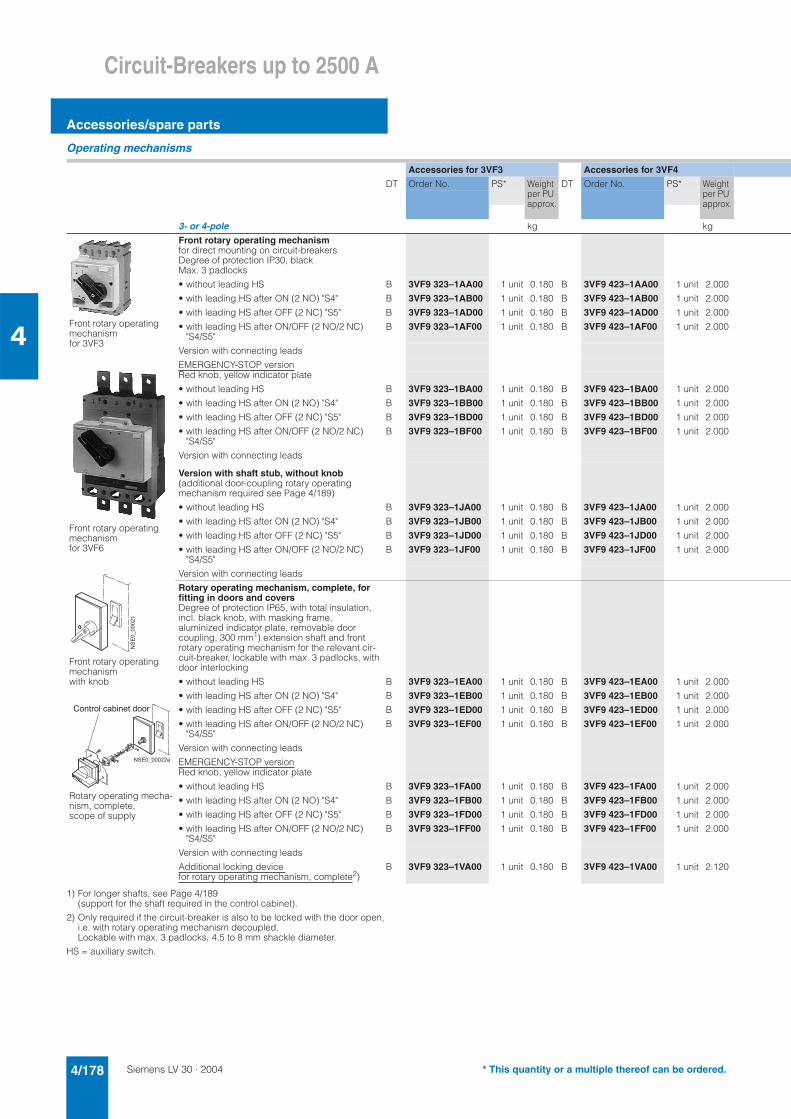
Siemens LV 30 · 20044/178
Circuit-Breakers up to 2500 A
Accessories/spare parts
4
Operating mechanisms
1) For longer shafts, see Page 4/189(support for the shaft required in the control cabinet).
2) Only required if the circuit-breaker is also to be locked with the door open, i.e. with rotary operating mechanism decoupled. Lockable with max. 3 padlocks, 4.5 to 8 mm shackle diameter.
HS = auxiliary switch.
Accessories for 3VF3 Accessories for 3VF4
DT Order No. PS* Weight per PU approx.
DT Order No. PS* Weight per PU approx.
3- or 4-pole kg kg
Front rotary operating mechanismfor direct mounting on circuit-breakersDegree of protection IP30, blackMax. 3 padlocks
• without leading HS B 3VF9 323–1AA00 1 unit 0.180 B 3VF9 423–1AA00 1 unit 2.000
• with leading HS after ON (2 NO) "S4" B 3VF9 323–1AB00 1 unit 0.180 B 3VF9 423–1AB00 1 unit 2.000
• with leading HS after OFF (2 NC) "S5" B 3VF9 323–1AD00 1 unit 0.180 B 3VF9 423–1AD00 1 unit 2.000
• with leading HS after ON/OFF (2 NO/2 NC) "S4/S5"
B 3VF9 323–1AF00 1 unit 0.180 B 3VF9 423–1AF00 1 unit 2.000
Version with connecting leads
EMERGENCY-STOP versionRed knob, yellow indicator plate
• without leading HS B 3VF9 323–1BA00 1 unit 0.180 B 3VF9 423–1BA00 1 unit 2.000
• with leading HS after ON (2 NO) "S4" B 3VF9 323–1BB00 1 unit 0.180 B 3VF9 423–1BB00 1 unit 2.000
• with leading HS after OFF (2 NC) "S5" B 3VF9 323–1BD00 1 unit 0.180 B 3VF9 423–1BD00 1 unit 2.000
• with leading HS after ON/OFF (2 NO/2 NC) "S4/S5"
B 3VF9 323–1BF00 1 unit 0.180 B 3VF9 423–1BF00 1 unit 2.000
Version with connecting leads
Version with shaft stub, without knob(additional door-coupling rotary operating mechanism required see Page 4/189)
• without leading HS B 3VF9 323–1JA00 1 unit 0.180 B 3VF9 423–1JA00 1 unit 2.000
• with leading HS after ON (2 NO) "S4" B 3VF9 323–1JB00 1 unit 0.180 B 3VF9 423–1JB00 1 unit 2.000
• with leading HS after OFF (2 NC) "S5" B 3VF9 323–1JD00 1 unit 0.180 B 3VF9 423–1JD00 1 unit 2.000
• with leading HS after ON/OFF (2 NO/2 NC) "S4/S5"
B 3VF9 323–1JF00 1 unit 0.180 B 3VF9 423–1JF00 1 unit 2.000
Version with connecting leads
Rotary operating mechanism, complete, for fitting in doors and coversDegree of protection IP65, with total insulation, incl. black knob, with masking frame, aluminized indicator plate, removable door coupling, 300 mm1) extension shaft and front rotary operating mechanism for the relevant cir-cuit-breaker, lockable with max. 3 padlocks, with door interlocking
• without leading HS B 3VF9 323–1EA00 1 unit 0.180 B 3VF9 423–1EA00 1 unit 2.000
• with leading HS after ON (2 NO) "S4" B 3VF9 323–1EB00 1 unit 0.180 B 3VF9 423–1EB00 1 unit 2.000
• with leading HS after OFF (2 NC) "S5" B 3VF9 323–1ED00 1 unit 0.180 B 3VF9 423–1ED00 1 unit 2.000
• with leading HS after ON/OFF (2 NO/2 NC) "S4/S5"
B 3VF9 323–1EF00 1 unit 0.180 B 3VF9 423–1EF00 1 unit 2.000
Version with connecting leads
EMERGENCY-STOP versionRed knob, yellow indicator plate
• without leading HS B 3VF9 323–1FA00 1 unit 0.180 B 3VF9 423–1FA00 1 unit 2.000
• with leading HS after ON (2 NO) "S4" B 3VF9 323–1FB00 1 unit 0.180 B 3VF9 423–1FB00 1 unit 2.000
• with leading HS after OFF (2 NC) "S5" B 3VF9 323–1FD00 1 unit 0.180 B 3VF9 423–1FD00 1 unit 2.000
• with leading HS after ON/OFF (2 NO/2 NC) "S4/S5"
B 3VF9 323–1FF00 1 unit 0.180 B 3VF9 423–1FF00 1 unit 2.000
Version with connecting leads
Additional locking device for rotary operating mechanism, complete2)
B 3VF9 323–1VA00 1 unit 0.180 B 3VF9 423–1VA00 1 unit 2.120
Front rotary operating mechanismfor 3VF3
Front rotary operating mechanismfor 3VF6
Front rotary operating mechanismwith knob
Rotary operating mecha-nism, complete, scope of supply
� � � � � � � � � � �
= � � � � � � � � 2 � � � � � ! � � �
���������
* This quantity or a multiple thereof can be ordered.
Siemens LV 30 · 2004 4/179
Circuit-Breakers up to 2500 A
Accessories/spare parts
4
Accessories for 3VF5 Accessories for 3VF6 Accessories for 3VF7 Accessories for 3VF8
DT Order No. PS* Weight per PU approx.
DT Order No. PS* Weight per PU approx.
DT Order No. PS* Weight per PU approx.
DT Order No. PS* Weight per PU approx.
kg kg kg kg
B 3VF9 523–1AA00 1 unit 1.080 B 3VF9 623–1AA00 1 unit 0.140 B 3VF9 723–1AA00 1 unit 3.680 B 3VF9 823–1AA01 1 unit 0.200
B 3VF9 523–1AB00 1 unit 1.080 B 3VF9 623–1AB00 1 unit 0.140 B 3VF9 723–1AB00 1 unit 3.680 B 3VF9 823–1AB01 1 unit 0.200
B 3VF9 523–1AD00 1 unit 1.080 B 3VF9 623–1AD00 1 unit 0.140 B 3VF9 723–1AD00 1 unit 3.680 B 3VF9 823–1AD01 1 unit 0.200
B 3VF9 523–1AF00 1 unit 1.080 B 3VF9 623–1AF00 1 unit 0.140 B 3VF9 723–1AF00 1 unit 3.680 B 3VF9 823–1AF01 1 unit 0.200
B 3VF9 523–1BA00 1 unit 1.080 B 3VF9 623–1BA00 1 unit 0.140 B 3VF9 723–1BA00 1 unit 3.680 B 3VF9 823–1BA01 1 unit 0.200
B 3VF9 523–1BB00 1 unit 1.080 B 3VF9 623–1BB00 1 unit 0.140 B 3VF9 723–1BB00 1 unit 3.680 B 3VF9 823–1BB01 1 unit 0.200
B 3VF9 523–1BD00 1 unit 1.080 B 3VF9 623–1BD00 1 unit 0.140 B 3VF9 723–1BD00 1 unit 3.680 B 3VF9 823–1BD01 1 unit 0.200
B 3VF9 523–1BF00 1 unit 1.080 B 3VF9 623–1BF00 1 unit 0.140 B 3VF9 723–1BF00 1 unit 3.680 B 3VF9 823–1BF01 1 unit 0.200
B 3VF9 523–1JA00 1 unit 1.080 B 3VF9 623–1JA00 1 unit 0.140 B 3VF9 723–1JA00 1 unit 3.680 B 3VF9 823–1JA01 1 unit 0.200
B 3VF9 523–1JB00 1 unit 1.080 B 3VF9 623–1JB00 1 unit 0.140 B 3VF9 723–1JB00 1 unit 3.680 B 3VF9 823–1JB01 1 unit 0.200
B 3VF9 523–1JD00 1 unit 1.080 B 3VF9 623–1JD00 1 unit 0.140 B 3VF9 723–1JD00 1 unit 3.680 B 3VF9 823–1JD01 1 unit 0.200
B 3VF9 523–1JF00 1 unit 1.080 B 3VF9 623–1JF00 1 unit 0.140 B 3VF9 723–1JF00 1 unit 3.680 B 3VF9 823–1JF01 1 unit 0.200
B 3VF9 523–1EA00 1 unit 1.080 B 3VF9 623–1EA00 1 unit 0.140 B 3VF9 723–1EA00 1 unit 3.680 B 3VF9 823–1EA01 1 unit 0.200
B 3VF9 523–1EB00 1 unit 1.080 B 3VF9 623–1EB00 1 unit 0.140 B 3VF9 723–1EB00 1 unit 3.680 B 3VF9 823–1EB01 1 unit 0.200
B 3VF9 523–1ED00 1 unit 1.080 B 3VF9 623–1ED00 1 unit 0.140 B 3VF9 723–1ED00 1 unit 3.680 B 3VF9 823–1ED01 1 unit 0.200
B 3VF9 523–1EF00 1 unit 1.080 B 3VF9 623–1EF00 1 unit 0.140 B 3VF9 723–1EF00 1 unit 3.680 B 3VF9 823–1EF01 1 unit 0.200
B 3VF9 523–1FA00 1 unit 1.080 B 3VF9 623–1FA00 1 unit 0.140 B 3VF9 723–1FA00 1 unit 3.680 B 3VF9 823–1FA01 1 unit 0.200
B 3VF9 523–1FB00 1 unit 1.080 B 3VF9 623–1FB00 1 unit 0.140 B 3VF9 723–1FB00 1 unit 3.680 B 3VF9 823–1FB01 1 unit 0.200
B 3VF9 523–1FD00 1 unit 1.080 B 3VF9 623–1FD00 1 unit 0.140 B 3VF9 723–1FD00 1 unit 3.680 B 3VF9 823–1FD01 1 unit 0.200
B 3VF9 523–1FF00 1 unit 1.080 B 3VF9 623–1FF00 1 unit 0.140 B 3VF9 723–1FF00 1 unit 3.680 B 3VF9 823–1FF01 1 unit 0.200
B 3VF9 523–1VA00 1 unit 1.080 B 3VF9 623–1VA00 1 unit 0.332 integrated in front rotary operating mechanism
integrated in front rotary operating mechanism
* This quantity or a multiple thereof can be ordered.
Siemens LV 30 · 20044/180
Circuit-Breakers up to 2500 A
Accessories/spare parts
4
Operating mechanisms
1) With control voltages of 380/400 V or 500 V a transformer is required: e.g. 400/230 V (380/220 V), Order No. 4AM34 42–5AT10–0FA0 e.g. 500/230 V, Order No. 4AM34 42–5FT10–0FA0. The motorized operating mechanism must be ordered for AC 50/60 Hz 220 V.
2) For local manual closing.
3) Do not use motorized operating mechanisms in combination with guide frames in the case of 3VF6/3VF7.
4) Not for DC voltages.
Accessories for 3VF3 Accessories for 3VF4
DT Order No. PS* Weight per PU approx.
DT Order No. PS* Weight per PU approx.
3- or 4-pole kg kg
Motorized operating mechanism1)degree of protection IP00 without locking device
AC 50/60 Hz DC
– 24 V B 3VF9 323–1MA20 1 unit 0.180 B 3VF9 423–1MA20 1 unit 2.00042 V 48 V B 3VF9 323–1MB10 1 unit 0.180 B 3VF9 423–1MB10 1 unit 2.000– 60 V B 3VF9 323–1MC20 1 unit 0.180 B 3VF9 423–1MC20 1 unit 2.000
110/127 V 110/127 V B 3VF9 323–1MD10 1 unit 0.180 B 3VF9 423–1MD10 1 unit 2.000220/240 V 220 V B 3VF9 323–1ME10 1 unit 0.180 B 3VF9 423–1ME10 1 unit 2.000
with locking device for 3 padlocks
AC 50/60 Hz DC
– 24 V B 3VF9 323–1NA20 1 unit 0.180 B 3VF9 423–1NA20 1 unit 2.120– 48 V – –42 V 48 V B 3VF9 323–1NB10 1 unit 0.180 B 3VF9 423–1NB10 1 unit 2.120– 60 V B 3VF9 323–1NC20 1 unit 0.180 B 3VF9 423–1NC20 1 unit 2.120
– 110/125 V – –110/127 V 110/127 V B 3VF9 323–1ND10 1 unit 0.180 B 3VF9 423–1ND10 1 unit 2.120220/240 V 220 V B 3VF9 323–1NE10 1 unit 0.180 B 3VF9 423–1NE10 1 unit 2.120
Motorized operating mechanism suitable for synchronizingDegree of protection IP00 with locking device for 3 padlocks
AC 50/60 Hz DC
– 24 V – C 3VF9 423–1QA20 1 unit 2.120– 48 V – –42 V 48 V – C 3VF9 423–1QB10 1 unit 2.120– 60 V – C 3VF9 423–1QC20 1 unit 2.120110/127 V 110/127 V – C 3VF9 423–1QD10 1 unit 2.120220/240 V 220 V – C 3VF9 423–1QE10 1 unit 2.120
Handle for motorized operating mechanisms suitable for synchronizing2)
– B 3VF9 623–1WB00 1 unit 0.332
Solenoid operating mechanism
AC 50/60 Hz 110/120 V B 3VF9 323–1SD30 1 unit 0.180 –
AC 50/60 Hz 220/240 V B 3VF9 323–1SE30 1 unit 0.180 –
DC 110/120 V B 3VF9 323–1SD20 1 unit 0.180 –
DC 220/240 V B 3VF9 323–1SE20 1 unit 0.180 –
Motorized operating mechanism for 3VF3
Motorized operating mechanism for 3VF4, 3VF5, 3VF6 (shown with 3VF6)
Motorized operating mechanism for 3VF8
Catalog LV 10 "Switchgear and Controlgear for Industry"
* This quantity or a multiple thereof can be ordered.
Siemens LV 30 · 2004 4/181
Circuit-Breakers up to 2500 A
Accessories/spare parts
4
Accessories for 3VF5 Accessories for 3VF6 Accessories for 3VF7 Accessories for 3VF8
DT Order No. PS* Weight per PU approx.
DT Order No. PS* Weight per PU approx.
DT Order No. PS* Weight per PU approx.
DT Order No. PS* Weight per PU approx.
kg kg kg kg
B 3VF9 523–1MA20 1 unit 1.080 B 3VF9 623–1MA20 1 unit 0.140 3) – –B 3VF9 523–1MB10 1 unit 1.080 B 3VF9 623–1MB10 1 unit 0.140 3) – –B 3VF9 523–1MC20 1 unit 1.080 B 3VF9 623–1MC20 1 unit 0.140 3) – –
B 3VF9 523–1MD10 1 unit 1.080 B 3VF9 623–1MD10 1 unit 2.500 3) – –B 3VF9 523–1ME10 1 unit 1.080 B 3VF9 623–1ME10 1 unit 2.500 3) – –
B 3VF9 523–1NA20 1 unit 1.080 B 3VF9 623–1NA20 1 unit 2.500 3) – –– – D 3VF9 723–1NB20 1 unit 3.680 3) B 3VF9 833–1NB20 1 unit 17.300
B 3VF9 523–1NB10 1 unit 1.080 B 3VF9 623–1NB10 1 unit 2.500 3) – –B 3VF9 523–1NC20 1 unit 1.080 B 3VF9 623–1NC20 1 unit 2.500 3) – –
– – D 3VF9 723–1ND20 1 unit 3.680 3) –B 3VF9 523–1ND10 1 unit 1.080 B 3VF9 623–1ND10 1 unit 2.500 3) D 3VF9 723–1ND30 1 unit 3.680 3)4) B 3VF9 833–1ND30 1 unit 17.300 4)B 3VF9 523–1NE10 1 unit 1.080 B 3VF9 623–1NE10 1 unit 2.500 3) D 3VF9 723–1NE30 1 unit 3.680 3)4) B 3VF9 833–1NE30 1 unit 17.300 4)
C 3VF9 523–1QA20 1 unit 1.080 C 3VF9 623–1QA20 1 unit 0.332 – –– – – –
C 3VF9 523–1QB10 1 unit 1.080 C 3VF9 623–1QB10 1 unit 0.332 – –C 3VF9 523–1QC20 1 unit 1.080 C 3VF9 623–1QC20 1 unit 0.332 – –C 3VF9 523–1QD10 1 unit 1.080 C 3VF9 623–1QD10 1 unit 0.332 – –C 3VF9 523–1QE10 1 unit 1.080 C 3VF9 623–1QE10 1 unit 0.332 – –
B 3VF9 623–1WB00 1 unit 0.332 B 3VF9 623–1WB00 1 unit 0.332 – –
– – – –
– – – –
– – – –
– – – –
* This quantity or a multiple thereof can be ordered.
Siemens LV 30 · 20044/182
Circuit-Breakers up to 2500 A
Accessories/spare parts
4
Connections
For 8US1 busbar adapter system, see Section 8 "Components for distribution systems".1) Not in conjunction with guide frames.
2) For easy removal of 3VF circuit-breakers when mounted in a row.
3) 3 sets required for 4-pole circuit-breakers.
4) Use plug-in circuit-breakers with connecting leads (see Page 4/171).
5) The guide frame cannot be used in combination with the motorized operat-ing mechanism for 3VF6 and 3VF7.
Accessories for 3VF3 Accessories for 3VF4
DT Order No. PS* Weight per PU approx.
DT Order No. PS* Weight per PU approx.
3- or 4-pole kg kg
Auxiliary conductor plug-in devicefor plug-in circuit-breakers/ withdrawable circuit-breakersExternal mounting on side of plug-in circuit-breaker1)
} 3VF9 624–1VA40 1 unit 0.258 } 3VF9 624–1VA40 1 unit 0.258
Fitted to rear of circuit-breaker – } 3VF9 524–1VA50 1 unit 0.429Additional lateral connector1) } 3VF9 624–1VJ40 1 unit 0.128 } 3VF9 624–1VJ40 1 unit 0.128Additional rear connector – } 3VF9 624–1VJ50 1 unit 0.158
Pull-out device2) B 3VF9 624–1VF00 1 unit 0.498 B 3VF9 624–1VF00 1 unit 0.498for plug-in circuit-breakers/plug-in bases
Position indicator switches – –for disconnected positionfor guide frame
Phase barrier3) B 3VF9 324–1RA10 1 set 0.189 B 3VF9 524–1RA10 1 set 0.429for main connection1 set = 2 units
3-pole onlyFront busbar connection pieces B 3VF9 324–1JA10 1 set 3.650 B 3VF9 424–1JA10 1 set 2.7601 set = 3 units
Rear terminals B 3VF9 324–1LD10 1 set 3.650 B 3VF9 424–1LD10 1 set 0.3801 set = 3 units
Terminal with phase barriers for flexible flat copper bars1 set = 3 units
with standard termi-nal, included inscope of supply of circuit-breaker (up to 160 A)
with standard ter-minal, included in scope of supply of circuit-breaker
Multiple feed-in terminal – –1 set = 3 units
Plug-in basecomplete with baseplate and2 terminal coversfor front connection B 3VF9 324–1FA10 1 unit 3.650 B 3VF9 424–1FA10 1 unit 2.760for circuit-breaker with ’RCD module
B 3VF9 324–1FE10 1 unit 3.650 B 3VF9 424–1FE10 1 unit 2.760
Plug-in basewith baseplatefor rear connection B 3VF9 324–1FB10 1 unit 3.650 B 3VF9 424–1FB10 1 unit 2.760for circuit-breaker with RCDmodule
B 3VF9 324–1FF10 1 unit 3.650 B 3VF9 424–1FF10 1 unit 2.760
Guide frame4)with baseplate and crank handlefor front connection – –for rear connection – –
Terminal covers IP30 } 3VF9 324–1NB10 1 set 0.146 } 3VF9 424–1NB10 1 set 0.160with integrated phase barriers for main connections
for cable connection for cable connection
1 set = 2 units
3VF9 524–1VA50Auxiliary conductor plug-in device for 3VF4/3VF5
3VF9 324–1LD10Rear terminal for 3VF3
3VF9 524–1FA10Plug-in base with baseplate for front connection for 3VF5
3VF9 724–1LD10Rear connections for 3VF7
����������
�������� !" #�� $"�$�"!�%���&��
����������
'�� !" #(��!� �()�#�" %�*�
�)�#�" �%�*�
* This quantity or a multiple thereof can be ordered.
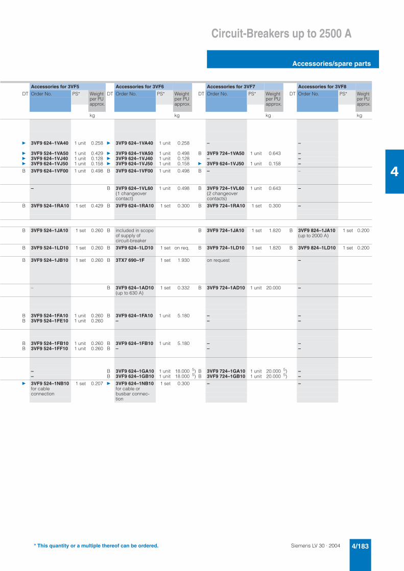
Siemens LV 30 · 2004 4/183
Circuit-Breakers up to 2500 A
Accessories/spare parts
4
Accessories for 3VF5 Accessories for 3VF6 Accessories for 3VF7 Accessories for 3VF8
DT Order No. PS* Weight per PU approx.
DT Order No. PS* Weight per PU approx.
DT Order No. PS* Weight per PU approx.
DT Order No. PS* Weight per PU approx.
kg kg kg kg
} 3VF9 624–1VA40 1 unit 0.258 } 3VF9 624–1VA40 1 unit 0.258 – –
} 3VF9 524–1VA50 1 unit 0.429 } 3VF9 624–1VA50 1 unit 0.498 B 3VF9 724–1VA50 1 unit 0.643 –} 3VF9 624–1VJ40 1 unit 0.128 } 3VF9 624–1VJ40 1 unit 0.128 – –} 3VF9 624–1VJ50 1 unit 0.158 } 3VF9 624–1VJ50 1 unit 0.158 } 3VF9 624–1VJ50 1 unit 0.158 –
B 3VF9 624–1VF00 1 unit 0.498 B 3VF9 624–1VF00 1 unit 0.498 B – –
– B 3VF9 624–1VL60 1 unit 0.498 B 3VF9 724–1VL60 1 unit 0.643 –(1 changeover contact)
(2 changeover contacts)
B 3VF9 524–1RA10 1 set 0.429 B 3VF9 624–1RA10 1 set 0.300 B 3VF9 724–1RA10 1 set 0.300 –
B 3VF9 524–1JA10 1 set 0.260 B included in scope of supply of circuit-breaker
B 3VF9 724–1JA10 1 set 1.820 B 3VF9 824–1JA10 1 set 0.200(up to 2000 A)
B 3VF9 524–1LD10 1 set 0.260 B 3VF9 624–1LD10 1 set on req. B 3VF9 724–1LD10 1 set 1.820 B 3VF9 824–1LD10 1 set 0.200
B 3VF9 524–1JB10 1 set 0.260 B 3TX7 690–1F 1 set 1.930 on request –
– B 3VF9 624–1AD10 1 set 0.332 B 3VF9 724–1AD10 1 unit 20.000 –(up to 630 A)
B 3VF9 524–1FA10 1 unit 0.260 B 3VF9 624–1FA10 1 unit 5.180 – –B 3VF9 524–1FE10 1 unit 0.260 – – –
B 3VF9 524–1FB10 1 unit 0.260 B 3VF9 624–1FB10 1 unit 5.180 – –B 3VF9 524–1FF10 1 unit 0.260 B – – –
– B 3VF9 624–1GA10 1 unit 18.000 5) B 3VF9 724–1GA10 1 unit 20.000 5) –– B 3VF9 624–1GB10 1 unit 18.000 5) B 3VF9 724–1GB10 1 unit 20.000 5) –
} 3VF9 524–1NB10 1 set 0.207 } 3VF9 624–1NB10 1 set 0.300 – –for cableconnection
for cable or busbar connec-tion
* This quantity or a multiple thereof can be ordered.
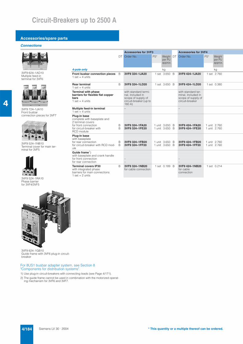
Siemens LV 30 · 20044/184
Circuit-Breakers up to 2500 A
Accessories/spare parts
4
Connections
For 8US1 busbar adapter system, see Section 8 "Components for distribution systems".1) Use plug-in circuit-breakers with connecting leads (see Page 4/171).
2) The guide frame cannot be used in combination with the motorized operat-ing mechanism for 3VF6 and 3VF7.
Accessories for 3VF3 Accessories for 3VF4
DT Order No. PS* Weight per PU approx.
DT Order No. PS* Weight per PU approx.
4-pole only kg kg
Front busbar connection pieces B 3VF9 324–1JA20 1 set 3.650 B 3VF9 424–1JA20 1 set 2.7601 set = 4 units
Rear terminal B 3VF9 324–1LD20 1 set 3.650 B 3VF9 424–1LD20 1 set 0.3801 set = 4 units
Terminal with phase barriers for flexible flat copper bars
with standard termi-nal, included in scope of supply of circuit-breaker (up to 160 A)
with standard ter-minal, included in scope of supply of circuit-breaker1 set = 4 units
Multiple feed-in terminal – –1 set = 4 units
Plug-in basecomplete with baseplate and2 terminal coversfor front connection B 3VF9 324–1FA20 1 unit 3.650 B 3VF9 424–1FA20 1 unit 2.760for circuit-breaker with RCD module
B 3VF9 324–1FE20 1 unit 3.650 B 3VF9 424–1FE20 1 unit 2.760
Plug-in basewith baseplatefor rear connection B 3VF9 324–1FB20 1 unit 3.650 B 3VF9 424–1FB20 1 unit 2.760for circuit-breaker with RCD mod-ule
B 3VF9 324–1FF20 1 unit 3.650 B 3VF9 424–1FF20 1 unit 2.760
Guide frame1)with baseplate and crank handlefor front connection – –for rear connection – –
Terminal covers IP30 B 3VF9 324–1NB20 1 set 0.189 B 3VF9 424–1NB20 1 set 0.214with integrated phase barriers for main connections1 set = 2 units
for cable connection for cable connection
3VF9 724–1JA10Front busbar connection pieces for 3VF7
3VF9 524–1NB10Terminal cover for main ter-minal for 3VF5
3VF9 524–1RA10Phase barrier for 3VF4/3VF5
3VF9 624–1GB10Guide frame with 3VF6 plug-in circuit-breaker
3VF9 624–1AD10Multiple feed-in terminal for 3VF6
* This quantity or a multiple thereof can be ordered.

Siemens LV 30 · 2004 4/185
Circuit-Breakers up to 2500 A
Accessories/spare parts
4
Accessories for 3VF5 Accessories for 3VF6 Accessories for 3VF7 Accessories for 3VF8
DT Order No. PS* Weight per PU approx.
DT Order No. PS* Weight per PU approx.
DT Order No. PS* Weight per PU approx.
DT Order No. PS* Weight per PU approx.
kg kg kg kg
B 3VF9 524–1JA20 1 set 0.260 included in scope of supply of circuit-breaker
B 3VF9 724–1JA20 1 set 1.820 C 3VF9 824–1JA20 1 set 0.200(up to 2000 A)
B 3VF9 524–1LD20 1 set 0.260 B 3VF9 624–1LD20 1 set on req. B 3VF9 724–1LD20 1 set 0.300 C 3VF9 824–1LD20 1 set 0.200
B 3VF9 524–1JB20 1 set 0.260 B 3TX7 690–1F 1 set 1.930 on request –
– B 3VF9 624–1AD20 1 unit 5.180 B 3VF9 724–1AD20 1 unit 20.000 –(up to 630 A)
B 3VF9 524–1FA20 1 unit 0.260 B 3VF9 624–1FA20 1 unit 5.180 – –B 3VF9 524–1FE20 1 unit 0.260 – – –
B 3VF9 524–1FB20 1 unit 0.260 B 3VF9 624–1FB20 1 unit 5.180 – –B 3VF9 524–1FF20 1 unit 0.260 – – –
– B 3VF9 624–1GA20 1 unit 18.000 2) B 3VF9 724–1GA20 1 unit 20.000 2) –– B 3VF9 624–1GB20 1 unit 18.000 2) B 3VF9 724–1GB20 1 unit 20.000 2) –
B 3VF9 524–1NB20 1 set 0.270 B 3VF9 624–1NB20 1 set 0.391 – –for cable-connection
for cable or busbar connection
* This quantity or a multiple thereof can be ordered.
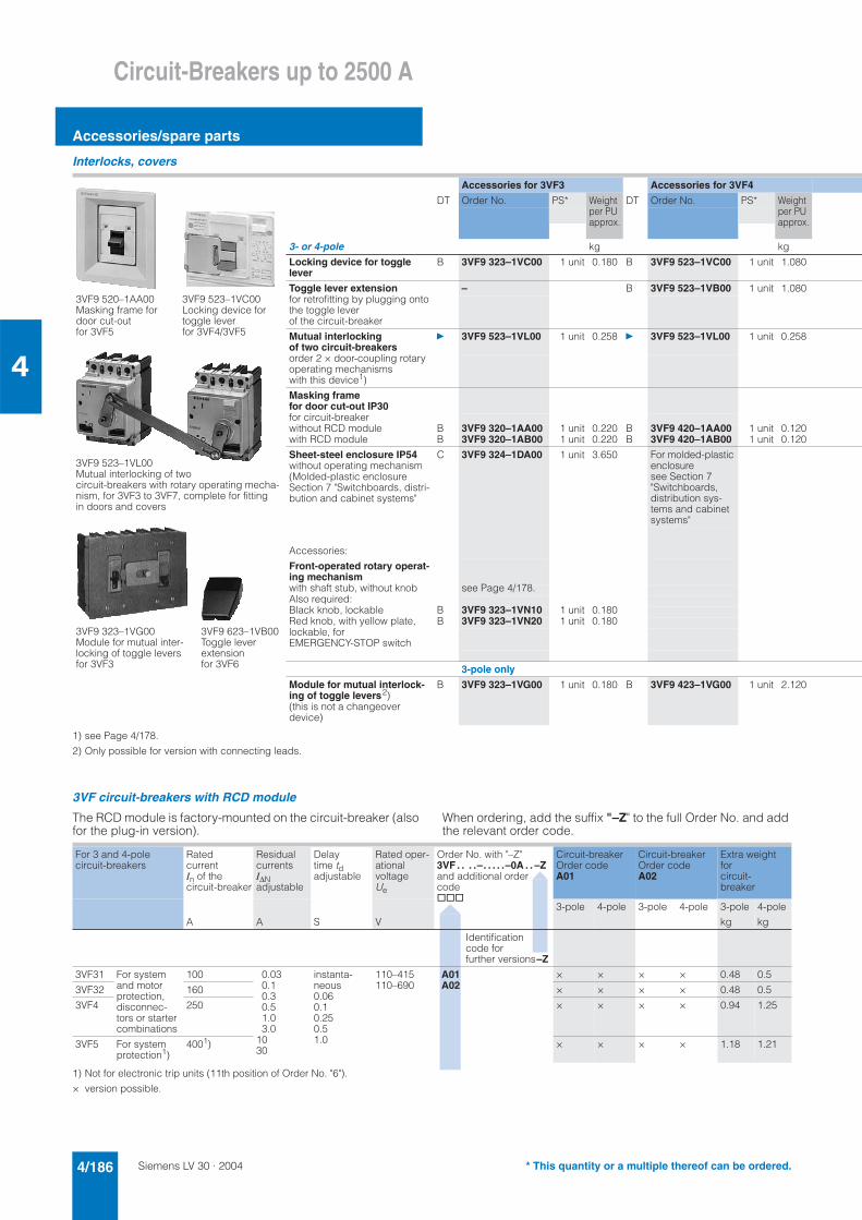
Siemens LV 30 · 20044/186
Circuit-Breakers up to 2500 A
Accessories/spare parts
4
* This quantity or a multiple thereof can be ordered.
Interlocks, covers
1) see Page 4/178.
2) Only possible for version with connecting leads.
3VF circuit-breakers with RCD module
The RCD module is factory-mounted on the circuit-breaker (also for the plug-in version).
When ordering, add the suffix "–Z" to the full Order No. and add the relevant order code.
1) Not for electronic trip units (11th position of Order No. "6").
× version possible.
Accessories for 3VF3 Accessories for 3VF4
DT Order No. PS* Weight per PU approx.
DT Order No. PS* Weight per PU approx.
3- or 4-pole kg kg
Locking device for toggle lever
B 3VF9 323–1VC00 1 unit 0.180 B 3VF9 523–1VC00 1 unit 1.080
Toggle lever extension – B 3VF9 523–1VB00 1 unit 1.080for retrofitting by plugging ontothe toggle lever of the circuit-breaker
Mutual interlocking of two circuit-breakers
} 3VF9 523–1VL00 1 unit 0.258 } 3VF9 523–1VL00 1 unit 0.258
order 2 × door-coupling rotary operating mechanisms with this device1)
Masking frame for door cut-out IP30for circuit-breakerwithout RCD module B 3VF9 320–1AA00 1 unit 0.220 B 3VF9 420–1AA00 1 unit 0.120with RCD module B 3VF9 320–1AB00 1 unit 0.220 B 3VF9 420–1AB00 1 unit 0.120
Sheet-steel enclosure IP54without operating mechanism
C 3VF9 324–1DA00 1 unit 3.650 For molded-plastic enclosure see Section 7 "Switchboards, distribution sys-tems and cabinet systems"
(Molded-plastic enclosure Section 7 "Switchboards, distri-bution and cabinet systems"
Accessories:
Front-operated rotary operat-ing mechanismwith shaft stub, without knob see Page 4/178.Also required:Black knob, lockable B 3VF9 323–1VN10 1 unit 0.180Red knob, with yellow plate, B 3VF9 323–1VN20 1 unit 0.180lockable, for EMERGENCY-STOP switch
3-pole only
Module for mutual interlock-ing of toggle levers2)
B 3VF9 323–1VG00 1 unit 0.180 B 3VF9 423–1VG00 1 unit 2.120
(this is not a changeover device)
3VF9 520–1AA00Masking frame for door cut-out for 3VF5
3VF9 523–1VC00Locking device for toggle lever for 3VF4/3VF5
3VF9 323–1VG00Module for mutual inter-locking of toggle levers for 3VF3
3VF9 623–1VB00Toggle lever extension for 3VF6
3VF9 523–1VL00Mutual interlocking of two circuit-breakers with rotary operating mecha-nism, for 3VF3 to 3VF7, complete for fitting in doors and covers
For 3 and 4-pole circuit-breakers
RatedcurrentIn of the circuit-breaker
Residualcurrents I∆Nadjustable
Delaytime tdadjustable
Rated oper-ationalvoltage Ue
Order No. with "–Z"3VF . . . .–. . . . .–0A . . –Zand additional order code@@@
Circuit-breakerOrder code A01
Circuit-breakerOrder code A02
Extra weight forcircuit-breaker
A A S V
3-pole 4-pole 3-pole 4-pole 3-pole
kg
4-pole
kg
Identificationcode for further versions–Z
3VF31 For system and motor protection, disconnec-tors or starter combinations
100 0.030.10.30.51.03.0
1030
instanta-neous0.060.10.250.51.0
110–415110–690
A01 A02
× × × × 0.48 0.5
3VF32 160 × × × × 0.48 0.5
3VF4 250 × × × × 0.94 1.25
3VF5 For system protection1)
4001) × × × × 1.18 1.21
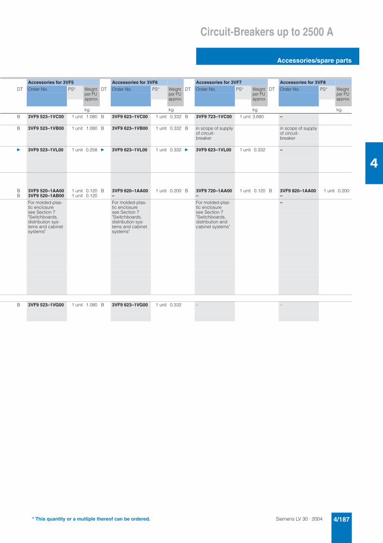
Siemens LV 30 · 2004 4/187
Circuit-Breakers up to 2500 A
Accessories/spare parts
4
Accessories for 3VF5 Accessories for 3VF6 Accessories for 3VF7 Accessories for 3VF8
DT Order No. PS* Weight per PU approx.
DT Order No. PS* Weight per PU approx.
DT Order No. PS* Weight per PU approx.
DT Order No. PS* Weight per PU approx.
kg kg kg kg
B 3VF9 523–1VC00 1 unit 1.080 B 3VF9 623–1VC00 1 unit 0.332 B 3VF9 723–1VC00 1 unit 3.680 –
B 3VF9 523–1VB00 1 unit 1.080 B 3VF9 623–1VB00 1 unit 0.332 B in scope of supply in scope of supplyof circuit- of circuit-breaker breaker
} 3VF9 523–1VL00 1 unit 0.258 } 3VF9 623–1VL00 1 unit 0.332 } 3VF9 623–1VL00 1 unit 0.332 –
B 3VF9 520–1AA00 1 unit 0.120 B 3VF9 620–1AA00 1 unit 0.200 B 3VF9 720–1AA00 1 unit 0.120 B 3VF9 820–1AA00 1 unit 0.200B 3VF9 520–1AB00 1 unit 0.120 – – –
For molded-plas-tic enclosure see Section 7 "Switchboards, distribution sys-tems and cabinet systems"
For molded-plas-tic enclosure see Section 7 "Switchboards, distribution sys-tems and cabinet systems"
For molded-plas-tic enclosure see Section 7 "Switchboards, distribution and cabinet systems"
–
B 3VF9 523–1VG00 1 unit 1.080 B 3VF9 623–1VG00 1 unit 0.332 – –
* This quantity or a multiple thereof can be ordered.
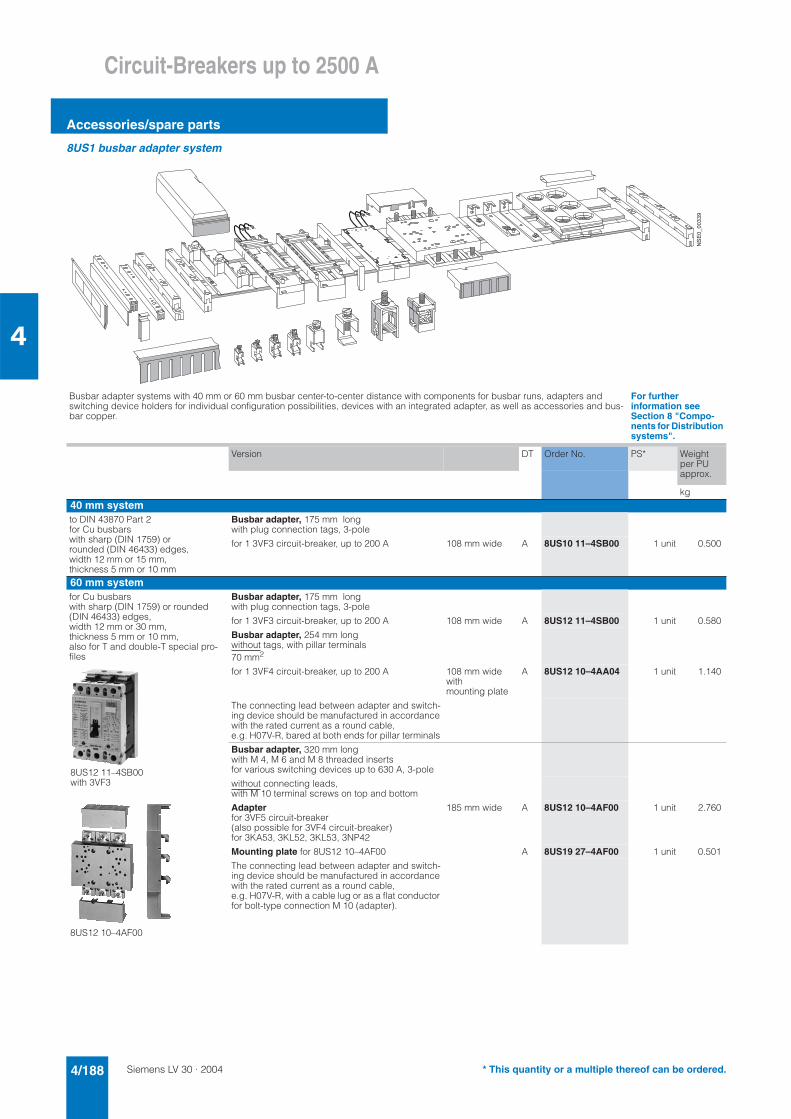
Siemens LV 30 · 20044/188
Circuit-Breakers up to 2500 A
Accessories/spare parts
4
8US1 busbar adapter system
Busbar adapter systems with 40 mm or 60 mm busbar center-to-center distance with components for busbar runs, adapters and switching device holders for individual configuration possibilities, devices with an integrated adapter, as well as accessories and bus-bar copper.
For further information see Section 8 "Compo-nents for Distribution systems".
Version DT Order No. PS* Weight per PU approx.
kg40 mm systemto DIN 43870 Part 2 for Cu busbars with sharp (DIN 1759) or rounded (DIN 46433) edges, width 12 mm or 15 mm, thickness 5 mm or 10 mm
Busbar adapter, 175 mm long with plug connection tags, 3-pole
for 1 3VF3 circuit-breaker, up to 200 A 108 mm wide A 8US10 11–4SB00 1 unit 0.500
60 mm systemfor Cu busbars with sharp (DIN 1759) or rounded (DIN 46433) edges, width 12 mm or 30 mm, thickness 5 mm or 10 mm, also for T and double-T special pro-files
Busbar adapter, 175 mm long with plug connection tags, 3-pole
for 1 3VF3 circuit-breaker, up to 200 A 108 mm wide A 8US12 11–4SB00 1 unit 0.580
Busbar adapter, 254 mm longwithout tags, with pillar terminals 70 mm2
for 1 3VF4 circuit-breaker, up to 200 A 108 mm wide withmounting plate
A 8US12 10–4AA04 1 unit 1.140
The connecting lead between adapter and switch-ing device should be manufactured in accordance with the rated current as a round cable, e.g. H07V-R, bared at both ends for pillar terminals
Busbar adapter, 320 mm long with M 4, M 6 and M 8 threaded inserts for various switching devices up to 630 A, 3-pole
without connecting leads, with M 10 terminal screws on top and bottom
Adapterfor 3VF5 circuit-breaker(also possible for 3VF4 circuit-breaker) for 3KA53, 3KL52, 3KL53, 3NP42
185 mm wide A 8US12 10–4AF00 1 unit 2.760
Mounting plate for 8US12 10–4AF00 A 8US19 27–4AF00 1 unit 0.501
The connecting lead between adapter and switch-ing device should be manufactured in accordance with the rated current as a round cable, e.g. H07V-R, with a cable lug or as a flat conductor for bolt-type connection M 10 (adapter).
���������$
8US12 11–4SB00 with 3VF3
8US12 10–4AF00
* This quantity or a multiple thereof can be ordered.
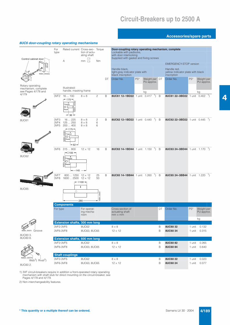
Siemens LV 30 · 2004 4/189
Circuit-Breakers up to 2500 A
Accessories/spare parts
4
8UC6 door-coupling rotary operating mechanisms
1) 3VF circuit-breakers require in addition a front-operated rotary operating mechanism with shaft stub for direct mounting on the circuit-breaker, see Pages 4/178 and 4/179.
2) Non-interchangeability features.
Fortype
Rated current
A
Cross-sec-tion of actu-ating shaft
mm
Torque
Nm
Door-coupling rotary operating mechanism, completeLockable with padlocks, with door interlockingSupplied with gasket and fixing screws
EMERGENCY-STOP version
Handle black,light-gray indicator plate with black inscription
Handle red, yellow indicator plate with black inscription
DT Order No. PS* Weight per PU approx.
DT Order No. PS* Weight per PU approx.
Illustrated:handle, masking frame kg kg
3VF2 16 ... 100 8 × 8 2 B 8UC61 12–1BD22 1 unit 0.417 1) B 8UC61 22–3BD22 1 unit 0.402 1)
3VF33VF43VF5
16 ... 225125 ... 250200 ... 400
8 × 88 × 88 × 8
266
B 8UC62 12–1BD22 1 unit 0.440 1) B 8UC62 22–3BD22 1 unit 0.445 1)
3VF6 315 ... 800 12 × 12 16 B 8UC63 14–1BD44 1 unit 1.150 1) B 8UC63 24–3BD44 1 unit 1.170 1)
3VF73VF8
800 ... 12501600 ... 2500
12 × 1212 × 12
2550
B 8UC65 14–1BB44 1 unit 1.260 1) B 8UC65 24–3BB44 1 unit 1.220 1)
ComponentsFor type For operat-
ing mecha-nism
Cross-section of actuating shaft mm × mm
DT Order No. PS* Weight per PU approx.
kgExtension shafts, 300 mm long3VF2-3VF5 8UC62 8 × 8 B 8UC60 32 1 unit 0.132
3VF6-3VF8 8UC63, 8UC65 12 × 12 B 8UC60 34 1 unit 0.315
Extension shafts, 600 mm long3VF2-3VF5 8UC62 8 × 8 B 8UC60 82 1 unit 0.265
3VF6-3VF8 8UC63, 8UC65 12 × 12 B 8UC60 84 1 unit 0.640
Shaft couplings3VF2-3VF5 8UC62 8 × 8 B 8UC60 22 1 unit 0.023
3VF6-3VF8 8UC63, 8UC65 12 × 12 B 8UC60 24 1 unit 0.077
Rotary operating mechanism, complete see Pages 4/178 and 4/179
8UC61
8UC62
8UC65
� � � � � � � � � � �
= � � � � � � � � 2 � � � � � ! � � �
75
36
Tripped
Reset
NS
E0_00362
75
62
Tripped
Reset
NS
E0_00363
100
140
Tripped
Reset
NS
E0_00364
NS
E0_
0036
1
100
280
8UC60 3.8UC60 8.
8UC60 2.
NSE0_00373
NSE0_00374
Groove
Web2) Rivet2)
* This quantity or a multiple thereof can be ordered.
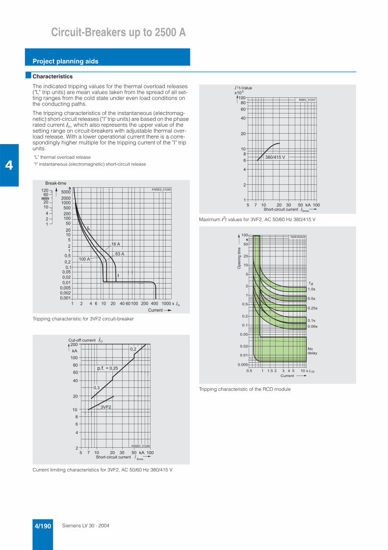
Siemens LV 30 · 20044/190
Circuit-Breakers up to 2500 A
Project planning aids
4
■ Characteristics
The indicated tripping values for the thermal overload releases ("L" trip units) are mean values taken from the spread of all set-ting ranges from the cold state under even load conditions on the conducting paths.
The tripping characteristics of the instantaneous (electromag-netic) short-circuit releases ("I" trip units) are based on the phase rated current In, which also represents the upper value of the setting range on circuit-breakers with adjustable thermal over-load release. With a lower operational current there is a corre-spondingly higher multiple for the tripping current of the "I" trip units.
Tripping characteristic for 3VF2 circuit-breaker
Current limiting characteristics for 3VF2, AC 50/60 Hz 380/415 V
Maximum I2t values for 3VF2, AC 50/60 Hz 380/415 V
Tripping characteristic of the RCD module
"L" thermal overload release
"I" instantaneous (electromagnetic) short-circuit release
� � � � , � � � � � � � � � � � � � � � �
� �
� �
� �
�
�
� � � �
� � � �
� � �
� � �
�
� + �
� � �
� �
� �
� �
�
�
� + �
� +
� + � �
� + � �
� + �
� + � � �
� + � � �
� + � �
� � �
� � � �
� � � �
� � � � � � � �
�
= � � � � � �
� � � � � 8 � � � �
�
� 1 � � � � � � � � �� �
� �
7 �
� �
�
� �
�
7
�
�
� � � � � � � �
� � �
� �
@
� + �
� + � �
� + �
� 6 # �
�
= � � 8 � ( ( � � � � � � � �3
� � � �
� � � � � 8 � � � � � � � � � � � � �
: ( :
� 1 � � � � � � � � �� �
� �
7 �
� �
�
� �
�
7
�
�
, ��
� � � � � � � 1
� 7 � < � � 6
� � � � � 8 � � � � � � � � � � � �
� � � 8 6 � � � ��
� � � �
���
��
�
�
�
��
��
�
� � � � � ����
�
�� ��������
��
�����
������
������
���
����
�����
����
����
���
���
��� ���
����
����
�����
����
�����
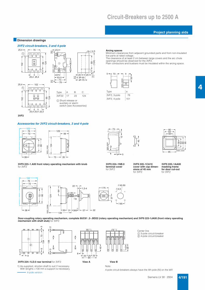
Siemens LV 30 · 2004 4/191
Circuit-Breakers up to 2500 A
Project planning aids
4
■ Dimension drawings
3VF2 circuit-breakers, 3 and 4-pole
Accessories for 3VF2 circuit-breakers, 3 and 4-pole
1) As-supplied, shorten shaft to suit if necessary. With lengths >130 mm a support is necessary.
4-pole version
Note:
4-pole circuit-breakers always have the 4th pole (N) on the left!
Arcing spacesMinimum clearances from adjacent grounded parts and from non-insulated live parts at rated voltage.The clearance of at least 2 cm between large covers and the arc chute openings should be observed for the 3VF2.Plain conductors and busbars must be insulated within the arcing space.
3VF2
1 �
��������1
� �
��
1
7$
��
1
7$
�
� � +
� � +
� � +
� � + � � +
� � +
� � +
��:�
1 �
1 7
� 1
� � : �
� �
B
B
�
��
, � � � � : �
7$
9�5
1
� ; 8 � �
; 8 1 �
� �� �
B
,
Type A B C
3VF22 17 23 124
$ Shunt release or auxiliary or alarm switch (see Accessories)
Type a
3VF2, 3-pole 78
3VF2, 4-pole 101
NS
E0_
0006
4
5 a73
50
3VF9 223–1.A00 front rotary operating mechanism with knob for 3VF2
3VF9 224–1NB.0 terminal coverfor 3VF2
3VF9 220–1CA10cover with cap dimen-sions of 45 mm for 3VF2
3VF9 220–1AA00masking frame for door cut-out for 3VF2
Door-coupling rotary operating mechanism, complete 8UC61 .2–.BD22 (rotary operating mechanism) and 3VF9 223-1JA00 (front rotary operating mechanism with shaft stub) for 3VF2
NS
E0_
0006
5
102129
73 35
5672
38
124
72
76
80
7345
9 5
NS
E0_
0006
6
12
12
45
5
NSE0_00067
58
95
9563 80
586380
1)
1,5-4
300
28
22
2257
65
75
37
42-50
4,5
8
31
NS
E0_
0006
8
38
124
35139
8072
102
7276
64
3VF9 224–1LD.0 rear terminal for 3VF2 View A View B
Center line$ 3-pole circuit-breaker% 4-pole circuit-breaker
NS
E0_
0006
9
7313
46
5
9
5
A
B
A
B
213
93
825 25 25
84
40 31 39
1
2
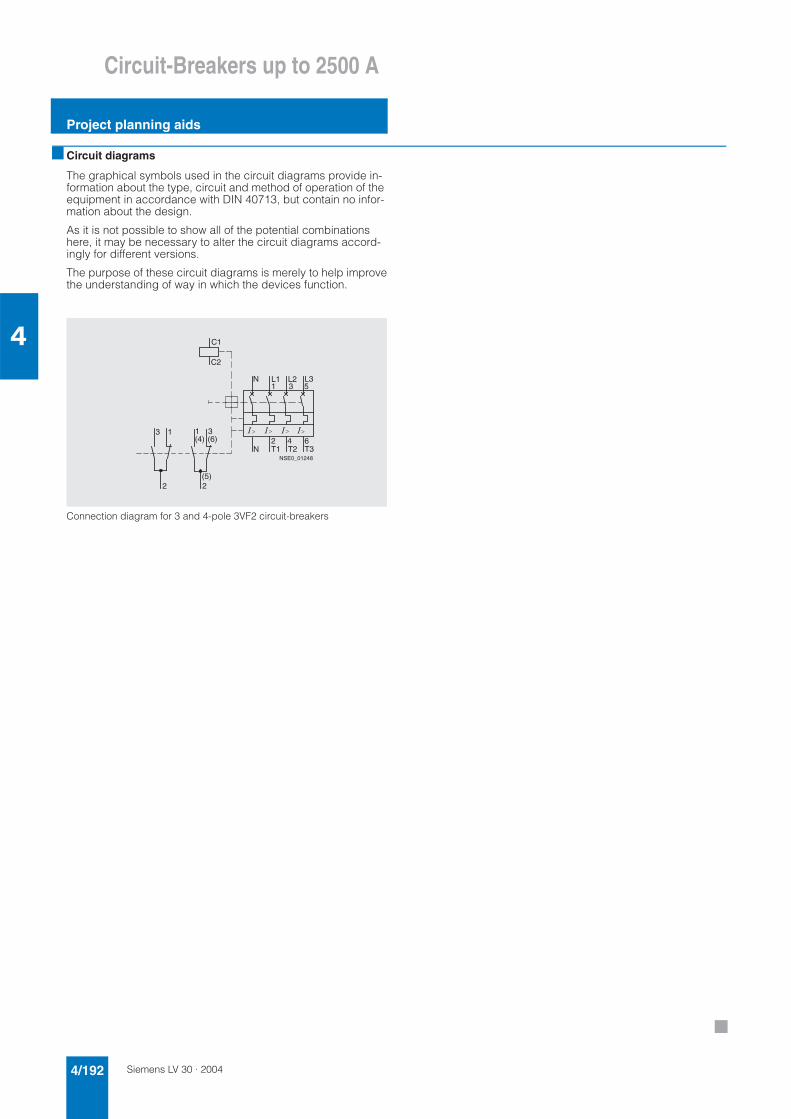
Siemens LV 30 · 20044/192
Circuit-Breakers up to 2500 A
Project planning aids
4
■ Circuit diagrams
The graphical symbols used in the circuit diagrams provide in-formation about the type, circuit and method of operation of the equipment in accordance with DIN 40713, but contain no infor-mation about the design.
As it is not possible to show all of the potential combinations here, it may be necessary to alter the circuit diagrams accord-ingly for different versions.
The purpose of these circuit diagrams is merely to help improvethe understanding of way in which the devices function.
Connection diagram for 3 and 4-pole 3VF2 circuit-breakers
1 3 5
NSE0_01248
C2
C1
N L1 L2 L3
2 4 6N T1 T2 T3
� � ��3 1
2
3(6)
2(5)
1(4)
■