molecular dynamics simulation on temperature and stain
TRANSCRIPT
Vol.:(0123456789)1 3
Applied Physics A (2018) 124:506 https://doi.org/10.1007/s00339-018-1918-5
Molecular dynamics simulation on temperature and stain rate-dependent tensile response and failure behavior of Ni-coated CNT/Mg composites
Xia Zhou1 · Xiaoxia Liu1 · Frederic Sansoz2 · Mengqi Shen1
Received: 26 January 2018 / Accepted: 16 June 2018 / Published online: 25 June 2018 © Springer-Verlag GmbH Germany, part of Springer Nature 2018
AbstractThis paper focuses on the molecular dynamics (MD) simulation of the tensile response of Ni-coated CNT-reinforced mag-nesium matrix composites (Ni-CNT/Mg) subjected to uniaxial tension at different temperatures and strain rates. The results show that Ni-CNTs can improve the mechanical properties of the composites effectively. The maximum stress of Ni-(6,6)CNT/Mg is, respectively, increased by 25.66 and 11.13%, while the elastic modulus is increased by 23.69 and 14.43% com-pared with those of the single-crystal Mg and uncoated (6,6)CNT/Mg at 300 K and 1 × 10⁹ s−1. In addition, the calculated elastic modulus of the Ni-(6,6)CNT/Mg composite is consistent with the prediction based on the rule-of-mixture. The Ni-CNT/Mg composites still have better mechanical properties at 500 K but exhibit a significant temperature softening effect in the temperature range 100–500 K and a strong positive strain-rate sensitivity at a strain rate greater than 1 × 10⁹ s−1. The various failure modes of the composite at the nano-scale are mainly determined by the combined effects of the different fac-tors such as the atomic disordering, the void and dislocation nucleation, structural phase transformations in Mg nanocrystals near the interface, and the subsequent fracture of the Ni-coated CNT close to the voids.
1 Introduction
Novel lightweight magnesium (Mg) alloys and Mg matrix nanocomposites are now considered having broad applica-tion prospects in the automobile, aerospace, and weapon industries due to their high strength-to-weight ratio and better combination of mechanical properties and energy absorption characteristics [1]. Currently, the research on
mechanical properties and failure mechanisms of nanosized particulate and whisker reinforced Mg-based composites at low strain rates has achieved some results [2]. Compared with nanoparticles and nanofibers, carbon nanotubes (CNTs) have been expected as ideal reinforcements for composites [3] due to their high aspect ratios, high strength, high tough-ness, and lightweight characteristics. As a result, CNT-rein-forced Mg matrix composites possess the potential to be the next generation structural materials, so it is necessary to quantificationally analyze the bonding characteristics between CNTs and Mg matrix and their influences on the macroscopic dynamic mechanical properties.
The uniform CNT dispersion and strong interface bond-ing are two key issues to obtain high strength and good duc-tility of Mg matrix composites reinforced by CNTs, while the interfacial bonding is one of the most significant chal-lenging issues that determines the efficiency of load transfer from the matrix to the CNTs. Existing experimental studies on the CNT/Mg interface are mostly focused on the inter-face microstructure characterization and interface chemis-try as well as their qualitative effects on the macroscopic mechanical properties of the composites [4, 5]. Liang et al. [4] fabricated 0.5 and 1.0 wt% Ni-CNT-reinforced AZ91D Mg alloy (Ni-CNTs/AZ91D) composites by ultrasonic
* Xia Zhou [email protected]
Xiaoxia Liu [email protected]
Frederic Sansoz [email protected]
Mengqi Shen [email protected]
1 State Key Laboratory of Structural Analysis for Industrial Equipment, Department of Engineering Mechanics, International Research Center for Computational Mechanics, Dalian University of Technology, Dalian 116024, People’s Republic of China
2 Department of Mechanical Engineering, The University of Vermont, Burlington, VT 05405, USA

X. Zhou et al.
1 3
506 Page 2 of 11
vibration method followed by extrusion. They found that the ultimate tensile strength (UTS) of the composite was increased by 17% after adding 0.5 wt% CNTs, while the UTS of the 1.0 wt% CNTs/AZ91D composite was less than that of AZ91D alloy. They believe that the fracture mode is the interface disengaged mechanism, but the interface between Ni-CNTs and Mg alloy requires further study. Investigations by Nai et al. [5] found that the presence of nickel coating on the CNT results in the formation of Mg2Ni intermetallics at the Ni-CNT/Mg interface, enhances the grain refinement and uniform dispersion of the Ni-CNT reinforcements in the Mg matrix, and so improves the micro-hardness, UTS and 0.2% yield strength of the monolithic Mg by 41, 39, and 64%, respectively.
Molecular dynamics (MD) simulation technique has been widely used in the study of interface behavior, because accu-rate interface measuring methods are difficult to be carried out and the interface description theory is not yet com-plete. Zhou et al. [6] studied the static tensile mechanical properties of Ni-CNT/Mg composite using MD simulation method. Their simulation results have verified and confirmed the effectiveness of Ni-CNTs in improving the mechanical properties of CNT/Mg composites. Song and Zha [7] ana-lyzed the uniaxial tension behavior of Ni-CNT-reinforced gold matrix composite using MD simulation method. They found that the mechanical properties of Ni-CNT/Au com-posites were obviously improved compared with those of the uncoated CNT-reinforced composite and they believed that nickel coating could provide an effective channel for interfa-cial stress transfer. Duan et al. [8] investigated the damping
characteristics of Ni-CNT-reinforced copper-matrix nano-composites at the atomic level and demonstrated that the distorted Cu lattice structure caused by the attraction of Ni is the dominant factor for the high damping rate of Ni-coated CNT/Cu composites.
In the present paper, to study improvement mechanism in mechanical properties and damage evolution behavior of Ni-coated CNT-reinforced Mg matrix composites undergoing dynamic loading conditions, MD simulation was conducted to investigate the tensile properties and failure behavior of Ni-coated armchair single-walled CNT/Mg composites under uniaxial tension by considering the coupled effects of temperature and strain rate. For convenience, the armchair SWCNT mentioned in this paper is denoted as CNT.
2 MD simulation approach
2.1 Simulation models
MD simulations of uniaxial tension of Ni-CNT/Mg compos-ites at different temperatures and strain rates were carried out using the Large-scale Atomic/Molecular Massively Parallel Simulator (LAMMPS) software [9] in this work. The MD simulation model of the Ni-(6,6)CNT/Mg composite is shown in Fig. 1. To represent the nano-scale structure inside a Ni-CNT/Mg composite, periodic boundary conditions (PBCs) were applied in the x, y, and z directions, while the x, y, and z axes are along the crystal orientation of [ ̄2110], [112̄ 0] and [0001] in hexagonal close packed (HCP) Mg single crystals,
Fig. 1 Atomic model of Ni-(6,6)CNT/Mg composite with a top view, b side view, and c embedded Ni-CNT in Mg. The red, blue, and yellow atoms denote magnesium, carbon, and nickel, respectively
Molecular dynamics simulation on temperature and stain rate-dependent tensile response and…
1 3
Page 3 of 11 506
respectively. In addition, the initial equilibrium positions of Ni atoms on CNT surfaces are all near the centers of carbon-atom hexagonal rings in CNTs [10], and the distance between Ni atoms and CNT surfaces is about 0.15 nm.
All composite models have the same Mg matrix geometry with various inner diameters of Ni-coated armchair CNTs, and the composite models have equal dimensions: length of 9.80 nm, width of 6.67 nm, and depth of 6.44 nm. The geomet-rical parameters of CNTs used in the MD models are shown in Table 1 and the CNTs with or without surface-coated nickel atoms are embedded in the center of the Mg matrix parallel to the axial tensile direction. Each model for Ni-coated (4,4)CNT, (6,6)CNT, (8,8)CNT, and (10,10)CNT-reinforced Mg composites contains 17,966 atoms (C: 640, Ni: 322, and Mg: 17,004), 18,160 atoms (C: 960, Ni: 480, and Mg: 16,720), 18,356 atoms (C: 1280, Ni: 640, and Mg: 16,436), and 18,550 atoms (C: 1600, Ni: 800, and Mg: 16,150), respectively.
2.2 Inter‑atomic interaction potentials
For MD simulation, the selection of potential function is a key factor to obtain reasonable results. In the present MD model, different potential functions were employed to describe the interactions of atoms. Herein, the empirical embedded-atom method (EAM) potential developed by Sun et al. [11] was adopted to describe the interactions between Mg atoms. The total energy Ei of an atom i is given by
where Fα is the embedding energy, which is a function of the atomic electron density ρβ; ϕαβ is a pair potential interac-tion, and α and β are the element types of atoms i and j. Both summations in the formula are over all neighbors j of atom i within the cut-off distance.
The C–C inter-atomic interactions were simulated using the adaptive intermolecular reactive bond-order (AIREBO) [12] potential with a cut-off radius of 2.0 Å [13]. The AIREBO potential is composed of the Reactive Empirical Bond-Order (REBO) potential, the Lennard–Jones (LJ) potential and the torsional interaction potential. It is expressed as
(1)Ei = F�
(Σj≠i
��(rij))
+1
2Σj≠i
���
(rij),
(2)E =1
2
∑i
∑j≠i
[EREBOij
+ ELJij+∑k≠i,j
∑l≠i,j,k
ETORSIONkijl
],
where the EREBOij
item describes short-ranged C–C interac-
tions with distance r < 2.0 Å. The ELJij
item adds longer
ranged interactions (2.0 Å < r < cut-off distance) using the standard 12-6 LJ potential. The ETORSION
ij term is an explicit
four-body potential that describes various dihedral angle preferences in hydrocarbon configurations.
The C–Ni and Ni–Ni interaction potential parameters were determined using the bond-order potential [14]. The functions of the bond-order potential are shown as follows:
where EC−Niij
and ENi−Niij
, respectively, denote the total poten-
tial energy in C–Ni and Ni–Ni atoms, and rij represents the distance between atoms i and j. The potential parameters S, β, b, and δ determine the shape of the potential function. The additional term B* is a function of carbon coordination num-ber NC of a metal atom. The binding energy De and the equi-librium bond length Re are expressed as direct functions of the metal coordination number NM. From the cut-off func-tion f(rij), the coordination numbers of NC
i and NM
i can be
(3)EC−Niij
=De
S − 1exp
�−�
√2S
�rij − Re
��
− B∗DeS
S − 1exp
�−�
√2∕S
�rij − Re
��
(4)B∗ ={1 + b
(NC − 1
)}�
(5)ENi−Niij
=De
S − 1exp
�−�
√2S
�rij − Re
��
−DeS
S − 1exp
�−�
√2∕S
�rij − Re
��
(6)De = De1 + De2exp{−CD
(NM − 1
)}
(7)Re = Re1 − Re2exp{−CR
(NM − 1
)}
(8)
f�rij�=
⎧⎪⎪⎨⎪⎪⎩
1 rij < R1
1
2
�1 + cos
𝜋�rij − R1
�R2 − R1
�R1 < rij < R2
0 rij > R2
(9)NCi= 1 +
∑carbon
f(rik)
(10)NMi
= 1 +∑metal
f(rik), NM
ij=(NMi+ NM
j
)/2,
Table 1 Geometrical parameters of armchair CNTs embedded in Mg matrix
Chirality index (4,4) (6,6) (8,8) (10,10)
Diameter (nm) 0.542 0.814 1.805 1.356Length (nm) 9.8 9.8 9.8 9.8Atom numbers 640 960 1280 1600

X. Zhou et al.
1 3
506 Page 4 of 11
obtained. The parameters used in this potential for the C–Ni and Ni–Ni interactions can be found in reference [14].
In addition, the interactions between Mg and C atoms or Mg and Ni atoms are modeled by the LJ potential [6]:
where ε is the depth of the potential well, σ is the distance where the inter-atomic potential is zero, and r is the distance between two atoms. The LJ (12-6) parameters are shown in Table 2.
2.3 Simulation details and calculation of stress at nano‑scale
Before starting the MD simulations of uniaxial tension, the initial configurations must be energy minimized to obtain a stable structure by the conjugate gradient method. Thus, the systems were thermally equilibrated to the set temperature such as 300 K under the NPT ensemble with a pressure of 0 bar by running 40,000 steps with a time step of 1 fs. During the relaxation process, the temperature was kept constant at a certain temperature with Nose–Hoover thermostat and the system press was adjusted using Parrinello–Rahman barostat. Relaxation time of 40 ps was found to be enough for differ-ent Ni-CNT/Mg composite systems to reach the equilibrium stage, while the system temperature and total energy were found constant after 10 ps. Figure 2 shows the energy conver-gence of four Ni-CNT/Mg composite systems with different CNT diameters at 300 K. After relaxation, these Ni-CNT/Mg composites were subjected to a uniaxial tensile loading. The tensile simulations were carried out with a pressure of 0 bar at different temperatures and strain rates in the positive direction of the z-axis (Fig. 1).
During uniaxial tensile simulation, the velocity-Verlet algorithm was used for the integral calculation of the classical Newton’s moving equation. The open-source visualization tool OVITO was utilized to visualize MD data and generate snap-shots [15]. The structure was characterized with the common neighbor analysis (CNA) technique to distinguish defects from HCP, FCC, and BCC environments.
In addition, the normal tensile stress at nano-scale has been calculated based on virial stress by the following equation:
(11)ELJ(r) = 4�
[(�
r
)12
−(�
r
)6],
(12)𝜎(r) =1
Ω
∑i
[−mi�i ⊗ �i +
1
2
∑i≠j
rij ⊗ f ij
],
where Ω is the total volume, and mi and νi are the mass and velocity of atom i, respectively. ⊗ represents the cross prod-uct operator of two vectors and rij is the relative displace-ment vector from atom i to atom j, while fij is the force that the atom j acts on the atom i [16] .
3 Results and discussion
3.1 Ni‑CNT effect on tensile properties of Mg and CNT/Mg composites
The tensile stress–strain curves of Ni-coated (6,6)CNT and uncoated (6,6)CNT-reinforced Mg composites as well as monolithic Mg at 300 K and 1 × 10⁹ s−1 are displayed in Fig. 3 for comparison. In the case of the monolithic Mg,
Table 2 Lennard–Jones parameters [6] of �Mg−C and �Mg−Ni for Ni-CNT/Mg interface
Parameters �Mg−C �Mg−Ni
ε (eV) 0.0028 0.0024σ (nm) 0.3502 0.2965
Fig. 2 Total energy variation during relaxation
Fig. 3 Stress–strain curves for Ni-(6,6)CNT/Mg,(6,6)CNT/Mg and monolithic Mg at 300 K and 1 × 10⁹ s−1

Molecular dynamics simulation on temperature and stain rate-dependent tensile response and…
1 3
Page 5 of 11 506
similar to the Ni-CNT/Mg composite model (Fig. 1b), the size of the monolithic Mg model was, respectively, 9.80 × 6.67 × 6.44 nm in the x, y, and z directions, and PBCs were also assigned to the x, y, and z directions. It can be seen that the stress–strain curves for the above three materials have different characteristics. During the initial elastic stage and the subsequent nonlinear elastic stage, stress–strain curves are not overlapped, indicating that the elastic prop-erties are sensitive to different materials. With the increase of applied strain, the Young’s modulus decreases slightly, which can be seen from the slight change in slope towards the end of elastic deformation. The Young’s modulus can be determined by linear regression analysis for the initial elastic stage [17]. Here, the Young’s modulus for the Ni-CNT/Mg composites is about 83.12 GPa, while those for the CNT/Mg composites and the monolithic Mg are 77.01 and 67.20 GPa, respectively. It can be found that good agreement in elastic modulus of single-crystal Mg between the present MD prediction (67.20 GPa) and existing calculation result (69.6 GPa) in reference [11] was achieved, preliminarily validating the applicability of our MD model. The enhance-ment in the elastic modulus of the Ni-CNT/Mg composites is directly correlated with the improved interface bonding of the Ni-CNT to the Mg matrix.
As mentioned before, the stress–strain curves at the initial elastic stages for the three materials (Fig. 3) differ a lot due to the contribution of the Ni-CNT to the elastic modulus. In fact, it can be easily seen that there is also a significant dif-ference for the stress–strain curves after the stress reaches the highest point (at this point, the stress is defined as peak stress). For the Ni-CNT/Mg, the CNT/Mg composites, and the monolithic Mg, there all exist an ever-decreasing stage of the stress due to the nucleation of defects and a stress flow stage because of the interaction of defects after the stress reaches the peak stress, but a second large stress decrease stage occurs in the stress–strain curves for the first two due to the CNT fracture (at this point, the stress is defined as fracture stress) and the fracture propagation. Compared with the uncoated (6,6)CNT/Mg composite and the monolithic Mg matrix, the peak stress for the Ni-(6,6)CNT/Mg compos-ite is, respectively, increased by 11.13 and 25.66%, while its fracture stress is separately increased by 28.47 and 223.64%, showing that the Ni-CNT also contributes significantly to the strength of the uncoated CNT/Mg composite and the Mg matrix.
To further investigate the effects of the inner diameter of CNT on the tensile behavior of Ni-CNTs and Ni-CNT/Mg composites, Ni-coated armchair CNTs and Ni-CNT/Mg matrix composites with different CNT chiral indexes are simulated, as shown in Figs. 4 and 5, respectively. It should be noted that the tensile simulation of the Ni-CNT along its axial direction was conducted under the identical conditions with those of Ni-CNT/Mg composites including
temperature, strain rate, and Ni-CNT volumes except for boundary conditions. With respect to the Ni-CNT, an axial periodic boundary and free boundary conditions in the other two directions were adopted, since the mechanical properties of CNTs were insensitive to the simulation box under PBCs [18]. The stress–strain curves of (4, 4), (6, 6), (8, 8), and (10, 10) Ni-CNTs are shown in Fig. 4 in which the table lists the elastic moduli of the Ni-CNTs calculated by linear regres-sion. It can be found from Fig. 4 that the predicted elastic modulus by MD simulations depends on the CNT diameter. The elastic modulus of Ni-(6,6)CNT with the diameter of 0.814 nm predicted by MD simulation is 788.18 GPa and it is close to that reported in reference [19] (747 GPa), thus further validating the present MD model. In addition, as can be observed from Fig. 5, the mechanical behaviors
Fig. 4 Stress–strain curves of Ni-CNTs with chirality of (4, 4), (6, 6), (8, 8), and (10, 10) at 300 K and 1 × 10⁹ s−1
Fig. 5 Stress–strain curves of Ni-CNT/Mg composites with different chiral indexes
X. Zhou et al.
1 3
506 Page 6 of 11
such as the elastic modulus, the peak stress, and the frac-ture stress are significantly improved with the increase in the inner diameter of the Ni-CNT. However, the fracture strain increases with the increase in the inner diameter of the Ni-CNT. This is because the tensile stress in the nano-tube is diameter dependent [18] and the strengthening of the Ni-CNT/Mg composite is dominated by the Ni-CNTs reinforcement, while the fracture behavior of the Ni-CNT/Mg composite maybe governed by more factors such as Ni-CNT size characteristics and deformation mechanisms [19].
It is worth noting that the elastic behavior of the Ni-CNT/Mg composites is CNT diameter dependent and the elas-tic modulus of the Ni-CNT/Mg composites is considerably enhanced with the increase in the inner diameter of the Ni-CNT. However, because the mechanical behaviors of the Ni-CNT/Mg composites are not sensitive to the dimension of the simulation model by exertion of periodic boundaries, the effective elastic modulus of the Ni-CNT/Mg composites could still be estimated by a simple and well established rule-of-mixtures (ROM) [20] expressed as follows:
where VNi-CNT and VMg are separately the volume fractions of the Ni-CNT and Mg matrix; ENi-CNT/Mg, ENi-CNT, and EMg are, respectively, the elastic moduli of the Ni-CNT/Mg com-posites, Ni-CNT, and Mg matrix. Here, the volume of the Ni-CNT can be approximated to be that of the CNT [21]. As such, the volume fractions of the Ni-CNT VNi−CNT and Mg matrix VMg in Ni-CNT/Mg composites can be, respectively, c a l c u l a t e d a s VNi−CNT =
2πRCNTt⋅l
V−[π(RCNT−t∕ 2)
2⋅l] a n d
VMg = 1 − VNi−CNT , where RCNT is the mean radius of the CNT, t is the wall thickness of the CNT and is about 0.34 nm, l is the length of the CNT, and V is the total volume of the Ni-CNT/Mg composite model.
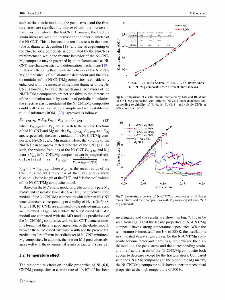
Based on the MD elastic modulus predictions of a pure Mg matrix and an isolated Ni-coated SWCNT, the effective elastic moduli of the Ni-CNT/Mg composites with different Ni-CNT inner diameters corresponding to chirality of (4, 4), (6, 6), (8, 8), and (10, 10) CNTs are estimated by the rule-of-mixture and are illustrated in Fig. 6. Meanwhile, the ROM-based calculated moduli are compared with the MD modulus predictions of the Ni-CNT/Mg composites with varied CNT diameter sizes. It is found that there is good agreement of the elastic moduli between the ROM-based calculated results and the present MD predictions for different inner diameter of Ni-CNT-reinforced Mg composites. In addition, the present MD predictions also agree well with the experimental results of Liao and Yuan [22].
3.2 Temperature effect
The temperature effect on tensile properties of Ni-(6,6)CNT/Mg composites at a strain rate of 1 × 10⁹ s−1 has been
(13)ENi−CNT∕Mg = EMgVMg + ENi−CNTVNi−CNT,
investigated and the results are shown in Fig. 7. It can be seen from Fig. 7 that the tensile properties of Ni-CNT/Mg composite have a strong temperature dependence. When the temperature is increased from 100 to 500 K, the oscillations in simulated stress–strain curves for the Ni-CNT/Mg com-posite become larger and more irregular; however, the elas-tic modulus, the peak stress and the corresponding strain, and the fracture strain of the Ni-CNT/Mg composite both appear to decrease except for the fracture stress. Compared with the CNT/Mg composite and the monolithic Mg matrix, the Ni-CNT/Mg composite still shows superior mechanical properties at the high temperature of 500 K.
Fig. 6 Comparison of elastic moduli predicted by MD and ROM for Ni-CNT/Mg composites with different Ni-CNT inner diameters cor-responding to chirality of (4, 4), (6, 6), (8, 8), and (10,10) CNTs at 300 K and 1 × 10⁹ s−1
Fig. 7 Stress–strain curves of Ni-CNT/Mg composites at different temperatures and their comparisons with Mg single crystal and CNT/Mg composite

Molecular dynamics simulation on temperature and stain rate-dependent tensile response and…
1 3
Page 7 of 11 506
Figure 8 shows the changes in tensile failure modes for Ni-CNT/Mg composites at the fracture strains with tem-peratures. It can be found from the composite configura-tion changes at failure that when the temperature is lower (100 K), the atomic structure is relative perfect at the begin-ning of tensile loading, the disordered atoms and subsequent micro-voids appear near the interface as the tensile process proceeds, the damage initiates from the micro-voids and propagates along the glide plane within the matrix, and finally, the Ni-CNT breaks near the interface pores. As the temperature increases from 100 to 500 K, there are more defects such as disordered atoms, point defects, dislocation, and slip bands in the Mg matrix and the near interface Mg matrix due to the increased atomic activity. In addition, the plastic deformation resistance for the Mg matrix and CNTs is weakened due to their structural changes during deforma-tion at high temperatures [23]. The damage at high tempera-tures can be formed and propagated from multiple defects at the same time. As a consequent, the defective CNTs fracture occurs near the interface with more defects after undergoing a certain degree of necking.
3.3 Strain‑rate effect
Figure 9 depicts the tensile stress–strain curves of Ni-CNT/Mg nanocomposites at 300 K and three typical strain rates, in which the longitudinal coordinates represent the average
Fig. 8 Snapshots of tensile failure modes for Ni-CNT/Mg composites at different temperatures of a T = 100 K, b T = 200 K, c T = 300 K, and d T = 500 K
Fig. 9 Tensile stress–strain curves of Ni-CNT/Mg composites at 300 K and three typical strain rates

X. Zhou et al.
1 3
506 Page 8 of 11
stress value of the Ni-CNT/Mg composites in the z (tensile) direction. It can be seen from Fig. 9 that the stress–strain curves for the Ni-CNT/Mg composites at different strain rates are completely coincident in the initial linear elastic stage during their tensile loading, indicating no obvious change in Young’s modulus of the composites with strain rate. This may be attributed to the little strain-rate sensitiv-ity of the elastic modulus of nanomaterials or is slightly decreased with the strain rate increases [24]. In addition, it is worth noting that there all exists a secondary declined stress stage in the stress–strain curves of the composites at different strain rates after the peak stress; however, at the lower strain rate (4 × 10⁸ s−1), the fluctuations in the stress–strain curves become larger after the second stress drop due to the Ni-CNT fracture, while at the higher strain rate (2 × 10¹⁰ s−1), the tensile stress decreases more slowly after it reaches the peak stress and the stress–strain curve is relatively smooth, so the peak stress and the corresponding strain is obviously increased. The variation in the stress–strain response after the elastic stage is related to the plastic deformation mecha-nism of the composites at different strain rates. The reasons for the different deformation mechanisms will be further analyzed in the following text.
The strain rate also influences the peak stress, corre-sponding tensile strain, fracture stress, and fracture strain of the Ni-CNT/Mg composites. Figure 10 presents the varia-tions in the peak stress, corresponding tensile strain, fracture stress, and fracture strain as a function of logarithmic strain rate for tensile deformation at 300 K. It can be seen from Fig. 10a, b that when the strain rate is lower than 1 × 10⁹ s−1, the peak stress, corresponding tensile strain, and fracture strain have little strain-rate sensitivity and their values are kept at 6.95 GPa, 9.5 and 11.5%, respectively. On the other side, when the strain rate is higher than 1 × 10⁹ s−1, the peak stress and corresponding tensile strain increase continuously with the strain rate, showing an obvious strain-rate hard-ening effect. Meanwhile, the fracture strain also increases
as the strain rate increases, but the increment magnitude (56.67%) is larger than that (33.69%) of the tensile strain at point corresponding to the peak stress when the strain rate increases from 1 × 10⁹ to 2 × 10¹⁰ s−1. This may be related to the nonlinear stress–strain relation at the later stage of the tensile stress–strain curve, which means that a small change in the fracture stress will result in a big change in the fracture strain. In contrast to the peak stress and corresponding ten-sile strain as well as fracture strain, the fracture stress shows a fluctuating increase with the increasing strain rate over the entire strain-rate range (Fig. 10b). This increasing trend in fracture stress can be attributed to the combined effects of strain-rate hardening and more defects at high strain rates. From the above, it can be concluded that increasing strain rate has the effect of improving the peak stress and fracture stress, but the strain-rate effect on the mechanical properties is less significant compared to the temperature effect [25], as presented in the previous section.
3.4 Tensile response and fracture at different temperatures and strain rates
Figure 11 shows the tensile stress–strain curves of Ni-CNT/Mg nanocomposites under the coupled effects of different temperatures (200, 300, 400, and 500 K) and strain rates (1 × 10⁹, 4 × 10⁹, 8 × 10⁹, and 2 × 10¹⁰ s−1). It is noted that there is a general increase in tensile stress with increasing strain rate, but a decrease with increasing temperature, indi-cating that the composites have strain-rate hardening and temperature softening effects. However, the temperature has a greater effect on stress at low strain rate than that at high strain rate, for instance, when the temperature is increased from 200 to 500 K, the peak stress is decreased by 33.84% at a lower strain rate of 1 × 10⁹ s−1 but only 28.81% at a higher strain rate of 2 × 10¹⁰ s−1. In addition, the stress–strain curves for the composites at different temperatures are a little dif-ferent in shape with the increase of strain rate, especially the
Fig. 10 Correlations between mechanical properties and strain rates in Ni-CNT/Mg composites at 300 K: a peak stress and corresponding strain and b fracture stress and fracture strain as a function of logarithmic strain rate

Molecular dynamics simulation on temperature and stain rate-dependent tensile response and…
1 3
Page 9 of 11 506
fracture stress and strain at low temperature show a general increasing trend with increasing strain rate.
Figure 12 shows the snapshots of tensile failure modes for Ni-CNT/Mg composites at the fracture strains under the coupled effects of different temperatures and strain rates. It can be seen that the failure processes of the composites under the coupled effects of different temperatures and strain rates are approximately the same to some degree. These pro-cesses involve initial microvoid formation, matrix cracking and crack propagation along the microvoid, and final CNT fracture. However, the deformation and failure mechanisms of the composites at different temperatures and strain rates are different.
As shown in Fig. 12a, the composite shows in general a “brittle fracture” mode and its fracture mainly occurs near the Ni-CNT/Mg interface at relatively high temperature and low strain rate. Under the above conditions, the disordered atoms and subsequent micro-voids preferentially appear near the interface, and the damage propagates along the glide plane inside the matrix and more dislocations are generated nearby. At last, the Ni-CNT fracture occurs at the expanded micro-voids near the interface due to the simultaneous bond
breaking in it, and the composite has a lower failure strain. As shown in Fig. 12b, c, when the temperature decreases and the strain rate increases, there are multiple fracture sites in the matrix and Ni-CNT as well as their interface during the failure of the composites, and the corresponding failure strain increases. The composite shows the “quasi-brittle frac-ture” characteristics. When the temperature is relative low and the strain rate is relative high, as shown in Fig. 10d, the composite is characterized by a “mixed fracture”. Under this condition, there are more slip bands, local amorphization and micro-voids in the matrix, and multiple damage failures have occurred in the matrix before the damage occurs at the interface. As a result, the multiple fracture of Ni-CNT occurs at the interface after undergoing a larger necking and the corresponding failure strain of the composite has the maximum value.
To further investigate the coupled effects of temperature and strain rate, the strain-rate sensitivity exponents at dif-ferent temperatures are calculated and analyzed. The strain-rate sensitivity exponent (m) measures how much a material changes in peak stress as strain-rate changes and it can be defined as follows [25]:
Fig. 11 Tensile stress–strain curves of Ni-CNT/Mg composites at the temperatures and strain rates of a T = 200–500 K and �̇� = 1 × 10⁹ s−1, b
T = 200–500 K and �̇� = 4 × 10⁹ s−1, c T = 200–500 K and �̇� = 8 × 10
9 s−1, and d T = 200–500 K and �̇� = 2 × 10¹⁰ s−1

X. Zhou et al.
1 3
506 Page 10 of 11
(14)m = 𝜕ln(𝜎)∕𝜕ln(�̇�)
Equation (14) shows that the strain-rate sensitivity coef-ficient m can be obtained from the slope of the fitting line of ln (�) vs. ln (�̇�) , as shown in Fig. 13. It can be seen that the strain-rate sensitivity exponent increases from 0.01678 to 0.04537 when the temperature ranges from 200 to 500 K. This indicates that the peak stress is more sensitive to strain rate at high temperatures. In the same way, it also can be found that the temperature effect on the peak stress is more significant at a low strain rate than that at a high strain rate. These conclusions are consistent with the summary results in Fig. 12.
4 Conclusions
1. MD simulations of uniaxial tension of Ni-CNT/Mg com-posites at different temperatures and strain rates have shown that the Ni-coated CNT can effectively enhance the elastic modulus and peak stress of the composites.
2. Temperature and strain rate have a strong influence on the tensile mechanical properties of Ni-CNT/Mg com-posites. The peak stress decreases by about 42.99% at 1 × 10⁹ s−1 when the temperature increases from 100 to
Fig. 12 Snapshots of tensile failure modes for Ni-CNT/Mg composites under the coupled effects of different temperatures and strain rates: a T = 500 K and �̇� = 1 × 10
9 s−1, b T = 400 K and �̇� = 4 × 10⁹ s−1, c T = 300 K and �̇� = 8 × 10
9 s−1, and d T = 200 K and �̇� = 2 × 10¹⁰ s−1
Fig. 13 Strain-rate sensitivity exponents of the peak stress in the plot of ln(�) vs. ln(�̇�) for Ni-CNT/Mg composites at different temperatures. The slope of the fitting line is the strain-rate sensitivity exponent

Molecular dynamics simulation on temperature and stain rate-dependent tensile response and…
1 3
Page 11 of 11 506
500 K, while the peak stress of Ni-CNT/Mg composite at the room temperature (300 K) increases by 12.76% as the strain rate increases from 1 × 10⁹ to 1 × 10¹⁰ s−1. Moreover, the mechanical properties of the composites are affected by the coupled effect of temperature and strain rate. The mechanical properties are more sensitive to high temperature at low strain rate, and reciprocally, to high strain rate at low temperature.
3. The Ni-CNT/Mg composite shows different failure modes under the coupled effects of different tempera-tures and strain rates. The composites show good overall mechanical behavior at low temperature and high strain rate.
Acknowledgements This work was supported by the National Nature Science Foundation of China (Grant numbers: 11272072, 11672055).
References
1. A. Dey, K.M. Pandey, Magnesium metal matrix composites—a review. Rev. Adv. Mater. Sci. 42, 58–67 (2015)
2. T.S. Srivatsan, C. Godbole, T. Quick, M. Paramsothy, M. Gupta, Mechanical behavior of a magnesium alloy nanocomposite under conditions of static tension and dynamic fatigue. J. Mater. Eng. Perform. 22, 439–453 (2013)
3. N. Silvestre, State-of-the-art review on carbon nanotube reinforced metal matrix composites. Intl. J. Compos. Mater. 3, 28–44 (2013)
4. J. Liang, H. Li, X. Hu, J. Wei, L. Qi, Fabrication of Ni-coated carbon nanotubes reinforced magnesium matrix composites, In: International Conference on Manipulation, Manufacturing and Measurement on the Nanoscale, IEEE, 2014, 299–302
5. M.H. Nai, J. Wei, M. Gupta, Interface tailoring to enhance mechanical properties of carbon nanotube reinforced magnesium composites. Mater. Design. 60, 490–495 (2014)
6. X. Zhou, S.Y. Song, L. Li, R.J. Zhang, Molecular dynamics simu-lation for mechanical properties of magnesium matrix composites reinforced with nickel-coated single-walled carbon nanotubes. J. Compos. Mater. 50, 191–200 (2016)
7. H.Y. Song, X.W. Zha, Mechanical properties of nickel-coated single-walled carbon nanotubes and their embedded gold matrix composites. Phys. Lett. A. 374, 1068–1072 (2010)
8. K. Duan, L. Li, Y.J. Hu, X.L. Wang, Damping characteristic of Ni-coated carbon nanotube/copper composite. Mater. Design. 133, 455–463 (2017)
9. LAMMPS Molecular Dynamics Simulator. Available at: http://www.cdc.gov/kawas aki/. Accessed January 9, 2018
10. S. Inoue, Y. Matsumura, Molecular dynamics simulation of physical vapor deposition of metals onto a vertically aligned
single-walled carbon nanotube surface. Carbon 46, 2046–2052 (2008)
11. D.Y. Sun, M.I. Mendelev, C.A. Becker, K. Kudin, T. Haxhimali, M. Asta, J.J. Hoyt, A. Karma, D.J. Srolovitz, Crystal-melt inter-facial free energies in hcp metals: A molecular dynamics study of Mg. Phys. Rev. B 73, (2006). 024116-1-024116-12
12. S.J. Stuart, A.B. Tutein, J.A. Harrison, A reactive potential for hydrocarbons with intermolecular interactions. J. Chem. Phys. 112, 6472–6486 (2000)
13. M. Sammalkorpi, A. Krasheninnikov, A. Kuronen, K. Nordlund, K. Kaski, Mechanical properties of carbon nanotubes with vacan-cies and related defects. Phys. Rev. B 70, 121–127 (2004)
14. Y. Shibuta, S. Maruyama, Bond-order Potential for transition metal carbide cluster for the growth simulation of a single-walled carbon nanotube. Comp. Mater. Sci. 39, 842–848 (2007)
15. A. Stukowski, Visualization and analysis of atomistic simulation data with OVITO-the Open Visualization Tool. Model. Simul. Mater. Sci. Eng. 18, 015012 (2010)
16. S. Lee, J. Park, J. Yang, W. Lu, Molecular dynamics simulations of the traction-separation response at the Interface between PVDF binder and graphite in the electrode of Li-ion batteries. J. Electro-chem. Soc. 161, A1218–A1223 (2014)
17. L. Li, M. Han, Molecular dynamics simulations on tensile behav-iors of single-crystal bcc Fe nanowire: effects of strain rates and thermal environment. Appl. Phys. A 123, 450 (2017)
18. J.F. Xiang, L.J. Xie, S.A. Meguid, S.Q. Pang, J. Yi, Y. Zhang, R. Liang, An atomic-level understanding of the strengthening mecha-nism of aluminum matrix composites reinforced by aligned carbon nanotubes. Comp. Mater. Sci. 128, 359–372 (2017)
19. F.L. Zhu, H.Y. Liao, K. Tang, Y.K. Chen, S. Liu, Molecular dynamics study on the effect of temperature on the tensile prop-erties of single-walled carbon nanotubes with a Ni-coating. J. Nanomater. 1–7 (2015) (2015)
20. N. Silvestre, B. Faria, J.N.C. Lopes, Compressive behavior of CNT-reinforced aluminum composites using molecular dynam-ics. Comp. Sci. Technol. 90, 16–24 (2014)
21. A.L. Kalamkarov, A.V. Georgiades, S.K. Rokkam, V.P. Veedu, M.N. Ghasemi-Nejhad, Analytical and numerical techniques to predict carbon nanotubes properties. Int. J. Solids. Struct. 43, 6832–6854 (2006)
22. L. Liao, Q.H. Yuan, Microstructure and mechanical properties of AZ91 alloy composites reinforced with Ni-coated carbon nano-tubes. Mater. Mech. Eng. 34, 92–95 (in Chinese) (2010)
23. S.F. Hassan, M. Paramsothy, Z.M. Gasem, F. Patel, M. Gupta, Effect of carbon nanotube on high-temperature formability of AZ31 magnesium alloy. J. Mater. Eng. Perform. 23, 2984–2991 (2014)
24. Y.G. Zhou, M. Hu, Mechanical behaviors of nanocrystalline Cu/SiC composites: An atomistic investigation. Comp. Mater. Sci. 129, 129–136 (2017)
25. M.Q. Chen, S.S. Quek, Z.D. Sha, C.H. Chiu, Q.X. Pei, Y.W. Zhang, Effects of grain size, temperature and strain rate on the mechanical properties of polycrystalline graphene – A molecular dynamics study. Carbon 85, 135–146 (2015)