molecular dynamics studies of low-energy atom impact...
TRANSCRIPT
Linkoping Studies in Science and TechnologyDissertation No. 1028
Molecular Dynamics Studies of Low-Energy Atom
Impact Phenomena on Metal Surfaces duringCrystal Growth
Dragan Adamovic
Department of Physics, Chemistry and BiologyLinkopings universitet, SE-581 83 Linkoping, Sweden
Linkoping 2006

ISBN 91-85523-56-9ISSN 0345-7524
Printed in Sweden by LiU-Tryck, Linkoping 2006

To my dear family

Abstract
It is a well-known fact in the materials science community that the use of low-energy atom impacts during thin film deposition is an effective tool for alteringthe growth behavior and for increasing the crystallinity of the films. However,the manner in which the incident atoms affect the growth kinetics and surfacemorphology is quite complicated and still not fully understood. This provides astrong incentive for further investigations of the interaction among incident atomsand surface atoms on the atomic scale. These impact-induced energetic events arenon-equilibrium, transient processes which complete in picoseconds. The only ac-cessible technique today which permits direct observation of these events is molec-ular dynamics (MD) simulations.
This thesis deals with MD simulations of low-energy atom impact phenomenaon metal surfaces during crystal growth. Platinum is chosen as a model systemgiven that it has seen extended use as a model surface over the past few decades,both in experiments and simulations. In MD, the classical equations of motion aresolved numerically for a set of interacting atoms. The atomic interactions are cal-culated using the embedded atom method (EAM). The EAM is a semi-empirical,pair-functional interatomic potential based on density functional theory. This po-tential provides a physical picture that includes many-atom effects while retainingcomputational efficiency needed for larger systems.
Single adatoms residing on a surface constitute the smallest possible clustersand are the fundamental components controlling nucleation kinetics. Small two-dimensional clusters on a surface are the result of nucleation and are presentduring the early stages of growth. These surface structures are chosen as targetsin the simulations (papers I and II) to provide further knowledge of the atomisticprocesses which occur during deposition, to investigate at which impact energiesthe different kinetic pathways open up, and how they may affect growth behav-ior. Some of the events observed are adatom scattering, dimer formation, clusterdisruption, formation of three-dimensional clusters, and residual vacancy forma-tion. Given the knowledge obtained, papers III and IV deal with growth of severallayers with the aim to study the underlying mechanisms responsible for altering
v

vi
growth behavior and how the overall intra- and interlayer atomic migration canbe controlled by low-energy atom impacts.
PREFACE
This thesis is a summary of the work I have carried out in the Theoretical PhysicsGroup and the Thin Film Physics Group at Linkopings University between June2000 and June 2006. The thesis is divided in two parts. The first part is intendedto give an introduction to the research field dealt with. The second part includesthe scientific papers.
Since I started my PhD studies, many people here at the physics departmenthave contributed to the progress in me gaining deeper knowledge in physics ingeneral and to the scientific work I have carried out. First and foremost, I wouldlike to express my deep gratitude to my supervisor Docent Peter Munger and co-adviser Docent Valeriu Chirita for their guidance and support over the years. Wehave had many discussions regarding the simulation results and how to write thescientific papers. It has truly been a learning process. A special thanks goes toLars Hultman and Joe Greene in providing additional guidance how to become abetter writer.
I would like to thank the senior staff of Theoretical and Computational Physicsgroups who gladly shared their knowledge. To my fellow, former and present, PhDstudents, diploma workers, and scholars, thank you for putting up with me andproviding support when needed. I would also like to thank the people in the ThinFilm group for inviting me to your yearly trips and for the discussions we have hadregarding experiments vs. computer simulations. Thank you Ingegard Anderssonfor all the help with administrative issues.
I acknowledge financial support from the Swedish Research Council (VR), andthe Swedish Foundation for Strategic Research (SSF) Strategic Research Centeron Materials Science and Nanoscale Surface Engineering.
I would also like to thank my friends outside the university for being there andfor all the things we have done together. We have lived the life, no doubt!
Dragan AdamovicLinkopings Universitet, 2006
vii

CONTENTS
1 Introduction. 1
2 Crystal growth. 3
2.1 Film growth from the vapor phase. . . . . . . . . . . . . . . . . . . 3
2.2 Growth modes. . . . . . . . . . . . . . . . . . . . . . . . . . . . . . 42.3 Film microstructure. . . . . . . . . . . . . . . . . . . . . . . . . . . 5
3 Low-energy atom impacts during crystal growth. 7
3.1 The basics. . . . . . . . . . . . . . . . . . . . . . . . . . . . . . . . 73.2 Surface and sub-surface effects. . . . . . . . . . . . . . . . . . . . . 83.3 Bombardment and substrate temperature. . . . . . . . . . . . . . . 93.4 Bombardment and growth modes. . . . . . . . . . . . . . . . . . . 9
3.5 Aims of the thesis. . . . . . . . . . . . . . . . . . . . . . . . . . . . 10
4 Molecular dynamics. 13
5 The embedded atom method. 17
5.1 Fundamentals. . . . . . . . . . . . . . . . . . . . . . . . . . . . . . 185.2 Phenomenology. . . . . . . . . . . . . . . . . . . . . . . . . . . . . . 195.3 Analytic forms. . . . . . . . . . . . . . . . . . . . . . . . . . . . . . 20
5.4 Applications. . . . . . . . . . . . . . . . . . . . . . . . . . . . . . . 225.5 Other methods. . . . . . . . . . . . . . . . . . . . . . . . . . . . . . 23
6 Simulation experiments. 25
6.1 Substrate specifics. . . . . . . . . . . . . . . . . . . . . . . . . . . . 256.2 Paper I. . . . . . . . . . . . . . . . . . . . . . . . . . . . . . . . . . 266.3 Paper II. . . . . . . . . . . . . . . . . . . . . . . . . . . . . . . . . . 266.4 Paper III. . . . . . . . . . . . . . . . . . . . . . . . . . . . . . . . . 27
6.5 Paper IV. . . . . . . . . . . . . . . . . . . . . . . . . . . . . . . . . 28
ix

x Contents
Paper I 31
Paper II 37
Paper III 59
Paper IV 75
CHAPTER 1
Introduction.
Before the invention of computers, more than half a century ago, the progress inscience was determined by the interplay of experiment and theory. An experimentis characterized by the set-up of a physical system which is then subjected to mea-surements, and results are obtained in numeric form. A theory is a representationof the physical system, usually in the form of mathematical equations. The modelis then authenticated by its ability to reproduce the system behavior for specifi-cally chosen circumstances. In many cases, approximations are required to carryout the calculations.
The advent of ’high-speed’ computers in 1960’s altered the conventional pic-ture of progress in science by introducing a new element in the interplay of theoryand experiment, the computer experiment. In a computer experiment, or a com-puter simulation, the model representing a system is provided by theorists and thecalculations are carried out by the computers. This often requires the knowledgein transforming the mathematical equations into a form that the computers canhandle.
By utilizing simulations, complexity can be introduced and more realistic sys-tems can be studied. This opens a path towards better understanding of theoryand experiment. However, it is important to realize that simulations play a muchmore significant role than validating experiments and or theories. In many cases,simulations are the only alternative. Needless to say, the birth of computer simu-lations is not only a link between theory and experiment it is also a powerful toolto propel progress in new directions.
Today, simulations are indispensable in most research areas. Many brancheswithin the scientific community conduct research in which the time evolution of asystem on the atomic scale is of great interest. An extensively used technique forsimulating the time evolution of a set of interacting atoms is molecular dynamics(MD). The method finds use, for example, in studying assembly phenomena dur-ing thin film growth.
1
2 Introduction.
The incentive for investigating growth on the atomic level by means of com-puter simulations is the need for increased fundamental knowledge, which can notbe obtained by experiments or theories alone, in order to meet the ever morestringent requirements on the quality of thin films for developing advanced micro-electronics, optical and magnetic devices, and coatings with enhanced mechanicalproperties.
But even if the knowledge to manufacture sophisticated thin-film applicationsare accessible, they will only find practical use if satisfying the industrial demandfor mass production at low cost. This, in turn, has led to the development of growthtechniques away from near-equilibrium deposition toward kinetically limited pro-cesses. One of the approaches being explored includes the use of low-energy, highflux ion irradiation1 at low temperatures.
Given that thermally activated atomistic processes are exponentially depressedat low temperatures, the focus turns to the events induced by single ion impacts.The latter are picosecond-events, and the only accessible technique today whichpermits direct observation of these non-equilibrium transient mechanisms is MDsimulations.
In order to conduct computer experiments in which the effects of single atomimpacts are studied, some 103 − 106 atoms and 103 − 109 time steps are required.Typically, several hundreds of simulations are carried out to provide statistics. Forthis purpose, semi-empirical, pair-functional models which are much less complexthan first-principles calculations but incorporates the necessary many-body effects,and are not much more computationally demanding than simple pair potentials,are commonly used for describing the atomic interactions.
This thesis deals with molecular dynamics studies of low-energy atom impactphenomena on metal surfaces during crystal growth from the vapor phase usingthe embedded atom method (EAM). The chapters are organized as follows. Inchapter 2, a brief summary of crystal growth from the vapor phase without bom-bardment is given. Chapter 3 is intended to illustrate the basics of low-energyion irradiation during deposition and the aims of this study. In chapter 4, thecomputational method for studying the time evolution of a set of atoms is given.The model describing the atomic interactions is presented in chapter 5. In chapter6 a summary of the included papers is given.
1The term ”ion irradiation” is used to refer to bombardment by fast neutrals as well as
accelerated ions.
CHAPTER 2
Crystal growth.
2.1 Film growth from the vapor phase.
Before discussing the effects of ion bombardment during deposition it is instructiveto go over the basics of film growth from the vapor phase without ion irradiation [1-3]. The thermally activated processes involved in the film evolution are governed bycharacteristic times determined by activation energies, attempt frequency factors,and the substrate temperature. The time scale for thermal events range frompicoseconds to miliseconds.
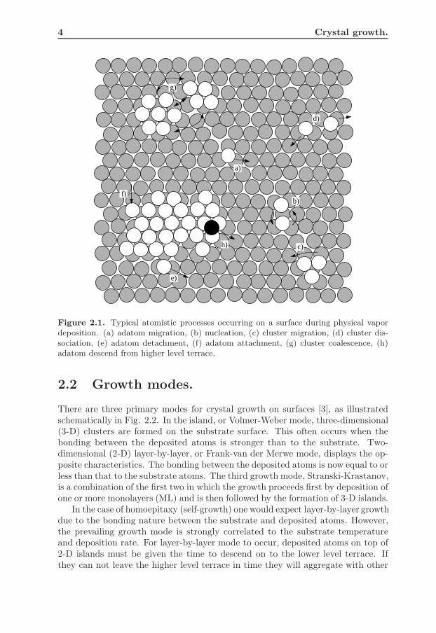
In the initial phase of film formation, two main processes take place, arrivalof atoms at the substrate and the migration of atoms (adatoms) on the substratesurface. This is illustrated schematically in Fig. 2.1. The adatoms migrate over thesurface via diffusive random hops before meeting other adatoms with the possibilityof creating a small cluster, a nucleus. A nucleus may capture additional atoms andin that way increase its size or it may dissociate releasing migrating adatoms. Thestability of a cluster increases with increasing size. In nucleation theory, the criticalisland size is defined as the size at which for the first time the island becomes morestable with the addition of just one more atom. This typically occurs with 3 or 4atoms, depending on the surface orientation.
As the deposition process continues, clusters grow larger by capturing mi-grating adatoms and subcritical clusters. Larger clusters may also grow at theexpense of neighboring smaller clusters by ripening. Eventually, clusters join, ei-ther by growth or migration. This coalescence continues and forms a network ofconnected clusters which is followed by the filling of the remaining voids resultingin a film with full coverage.
3
4 Crystal growth.
a)
b)
c)
d)
e)
f)
g)
h)
Figure 2.1. Typical atomistic processes occurring on a surface during physical vapordeposition. (a) adatom migration, (b) nucleation, (c) cluster migration, (d) cluster dis-sociation, (e) adatom detachment, (f) adatom attachment, (g) cluster coalescence, (h)adatom descend from higher level terrace.
2.2 Growth modes.
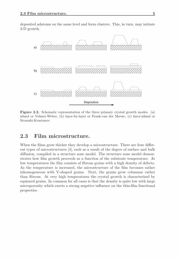
There are three primary modes for crystal growth on surfaces [3], as illustratedschematically in Fig. 2.2. In the island, or Volmer-Weber mode, three-dimensional(3-D) clusters are formed on the substrate surface. This often occurs when thebonding between the deposited atoms is stronger than to the substrate. Two-dimensional (2-D) layer-by-layer, or Frank-van der Merwe mode, displays the op-posite characteristics. The bonding between the deposited atoms is now equal to orless than that to the substrate atoms. The third growth mode, Stranski-Krastanov,is a combination of the first two in which the growth proceeds first by deposition ofone or more monolayers (ML) and is then followed by the formation of 3-D islands.
In the case of homoepitaxy (self-growth) one would expect layer-by-layer growthdue to the bonding nature between the substrate and deposited atoms. However,the prevailing growth mode is strongly correlated to the substrate temperatureand deposition rate. For layer-by-layer mode to occur, deposited atoms on top of2-D islands must be given the time to descend on to the lower level terrace. Ifthey can not leave the higher level terrace in time they will aggregate with other
2.3 Film microstructure. 5
deposited adatoms on the same level and form clusters. This, in turn, may initiate3-D growth.
a)
b)
c)
Deposition
Figure 2.2. Schematic representation of the three primary crystal growth modes. (a)island or Volmer-Weber, (b) layer-by-layer or Frank-van der Merwe, (c) layer-island orStranski-Krastanov.
2.3 Film microstructure.
When the films grow thicker they develop a microstructure. There are four differ-ent types of microstructures [4], each as a result of the degree of surface and bulkdiffusion, compiled in a structure zone model. The structure zone model demon-strates how film growth proceeds as a function of the substrate temperature. Atlow temperatures the film consists of fibrous grains with a high density of defects.As the temperature is increased, the microstructure of the film becomes ratherinhomogeneous with V-shaped grains. Next, the grains grow columnar ratherthan fibrous. At very high temperatures the crystal growth is characterized byequiaxed grains. In common for all cases is that the density is quite low with largemicroporosity which exerts a strong negative influence on the thin-film functionalproperties.

6
References.
[1] K. L. Chopra, Thin Film Phenomena, McGraw-Hill Book Company, Inc.(1969).
[2] Z. Zhang and M. G. Lagally, Science 276 (1997) 377.[3] J. A. Venables, G. D. T. Spiller, and M. Hanbucken, Rep. Prog. Phys. 47
(1984) 399.[4] P. B. Barna and M. Adamik, Thin Solid Films 317 (1998) 27.
CHAPTER 3
Low-energy atom impacts during crystal growth.
3.1 The basics.
The impingement of energetic atoms or ions on solid surfaces is known to producea wide variety of effects [1-4]. Many of these effects are beneficial for thin-filmdeposition while some are detrimental and can be avoided by keeping the energylow.
The actual energy transfer in the ion/surface interactions depend on the inci-dent ion and target atom mass. Considering a head-on binary elastic collision ofan incident ion of mass mi and kinetic energy Ei, and a target atom with massmt initially at rest, the transferred energy Tm is given by
Tm =4mimt
(mi + mt)2Ei = γEi . (3.1)
The energy transfer efficiency factor γ is the main feature of ion bombardment as itgives incident ions the ability to displace target (film) atoms. This individual factis responsible for altering the nucleation and coalescence kinetics during growth.
In the case of mi ∼ mt, Ei of only a few eV is sufficient to move a targetatom from one surface site to another. Incident ions with a few tens of eV can,in addition of activating surface processes, recoil into the sub-surface layers ordislodge surface atoms into the vapor phase. Thus, it appears that there is anenergy regime, ranging from a few eV to several tens of eV, for which incidentions can cause rearrangement of the surface but not of the bulk. This is usuallyreferred to as the ’low-energy’ range.
Note that if the mass of the incident ions is greater or smaller than the targetatoms, the irradiation energy has to be raised in order to provide similar effects interms of atomic displacements on the surface or in the sub-surface region comparedto the case where mi ∼ mt.
7
8 Low-energy atom impacts during crystal growth.
3.2 Surface and sub-surface effects.
Some of the impact-induced events that can occur on the surface and in the sub-surface region during low-energetic deposition are rather intuitive and what followsis a brief summary of the basic processes and their effect on the morphological de-velopment. The processes below will be labeled ’wanted’ or ’unwanted’ which areto be interpreted in the context of layer-by-layer growth since this type of growthmode is higly desirable for crystal growers. For simplicity of the discussion, theincident species are considered to be of the same type as the substrate atoms (ho-moepitaxy), however, some remarks on how the identified processes may affectheteroepitaxial growth will be given.
On an atomically flat surface, an incident atom can either be deposited di-rectly on the surface or it can recoil into the substrate. The latter can result intwo different reactions, both distinguished by the impact energy. Assuming thatthe incident energy is rather low, what follows is that a substrate atom is pushedup onto the surface. This particular type of process is usually labeled as an in-terlayer exchange event. In homoepitaxy, interlayer exchange is if no significance.However, in heteroepitaxy, it is usually of interest to keep the mixing probabilitybetween the two materials as low as possible in order to keep the interface sharp-ness high.
If the impact energy is raised, an interlayer exchange process can again occur,however, with two (or more) substrate atoms being pushed up onto the surface in-stead of only one, leaving one (or more) surface vacancies behind. These processesare usually identified as adatom/vacancy pair formation events. In heteropitaxythe vacancies can act as sinkholes for the other type of deposited material whichresults in intermixing. In homoepitaxy, adatom/vacancy pair formation can bothhave wanted and unwanted effects. Formation of additional adatoms can nucleatewith other nearby adatoms. This is typically considered to be a wanted effectif it occurs on the lowest level terrace as it can contribute in keeping the islandnumber density high. However, if adatom/vacancy formation occurs on a higherlevel terrace 3D growth can be accelerated which is an unwanted effect.
As the deposition process continues small islands will nucleate and some ofthem will be subjected to energetic impacts. Similar to bombardment of a flatsurface, a number of events involving the island atoms can be initiated. Thereare basically three main types of events that can occur. At rather low irradiationenergies, the incident atom will in most cases simply be deposited on top of theisland without causing any rearrangement involving the island. This is usually anunwanted effect since it can lead to nucleation on top of the island surface withother deposited adatoms which, in turn, can initiate 3D growth.
If the irradiation energy is increased, the impacts can induce a push-out pro-cess. This simply means that one of the outer island atoms is pushed to a neigh-boring surface site by the incident atom which settles at the formerly occupiedsurface site. These types of events are wanted since they act to keep the surfacetopograpy flat which promotes layer-by-layer growth.
At even higher impact energies, scattering of outer island atoms can occur. Areduction in island size during film growth is known to have two effects, a reduced
3.3 Bombardment and substrate temperature. 9
probability for arriving adatoms to be deposited on top of islands, and an increasedfrequency, for already deposited adatoms atop islands, to reach island edges andsubsequently descend onto the lower level terrace. Obviously, this promotes layer-by-layer growth and is a highly wanted feature.
3.3 Bombardment and substrate temperature.
Thermally activated atomic motion is present, in princinple, as long as the tem-perature is above 0 K, while bombardment-induced mass transport only dependson the impact energy (or energy transfer) and stops as soon as the excess ki-netic energy is dissipated through coupling into the surface. At low temperatures,where the thermally activated processes are exponentially depressed, the effects ofion-irradiation become increasingly significant. One could say that ion irradiationprovides the means of having high temperature processes (locally) while keepingthe substrate temperature low.
3.4 Bombardment and growth modes.
Low-energy (often < 100 eV) ion bombardment is an effective tool for altering thegrowth mode from 3-D, or island growth, to 2-D, or layer-by-layer growth, and isknown to increase the epitaxial thickness of films deposited at low temperatures[1-12]. The proposed model(s) explaining the growth mode transition is that ionbombardment enhances inter- and intralayer mass transport during deposition,leading to changes in initial nucleation and coalescence of islands which affect theoverall morphological development and microstructure evolution. For example, ithas been suggested that incident ions are responsible for suppressing 3D islandformation by removal of atoms from barely stable nuclei during the initial nucle-ation stages of growth. It has also been proposed that ion bombardment enhancesthe adatom number density via disruption of dimers which, in turn, results inhigher island nucleation rates. Another explanation is that during bombardment,adatoms are created via displacement of surface atoms and that these form oneor several adatom islands close to the impact site leading to an increased islandnumber density.
The manner in which low-energetic incident atoms affect the growth kineticsand surface morphology is quite complicated and still not fully understood. Thisprovides a strong incentive for further investigations of the interaction among inci-dent ions and surface atoms on the atomic scale. These impact-induced energeticevents are non-equilibrium transient processes which complete in picoseconds, andas such, not accessible even to state-of-the-art in situ experimental techniques,which can only detail initial and final states. The only accessible techniques to-day which permit direct observation of these events are computer simulations, inparticular molecular dynamics (MD) simulations [13-19].
10 Low-energy atom impacts during crystal growth.
3.5 Aims of the thesis.
The objective of this thesis is to employ MD simulations in order to provide furtherinsight into low-energy atom impact phenomena which occur during growth andhow they may affect growth behavior, specifically,
• To study the kinetic pathways as induced by low-energy atom impacts ofsingle adatoms and small 2-D clusters.
• To elucidate how the impact-induced processes affect nucleation, coalescence,and morphological development during growth.
• To demonstrate how the overall intra- and interlayer mass transport can becontrolled via low-energy single atom impacts during growth.
With a view to keep things simple, a metal is chosen as a model surface sincemetal bonds (in contrast to semiconductors or molecular materials) have essentiallyno directionality that can be used to direct atomic processes. To avoid furtherunnecessary complications, such as lattice mismatch and differences in surfaceenergy, the incident atoms are chosen to be of the same type as the substrateatoms (homoepitaxy).
In the included papers, Pt(111) is chosen as a model surface due to extensivefield ion microscopy [20-23] and scanning tunneling microscopy [24-29] data, andfor the simplicity of the existing semi-empirical models describing the cohesionof late transition metals. All papers deal with low-energy (5 - 50 eV) normallyincident Pt atom impacts on Pt(111).
The results and conclusions presented in the papers are expected to be vaild formost face-centered cubic (111) metallic planes as inferred by the strong similaritiesin the surface properties of these systems [29-32].
11
References.
[1] J. E. Greene, D. T. J. Hurle (Ed.), Handbook of Crystal Growth,Fundamentals, Part A, Vol. 1, North-Holland, Inc. (1993), p.639.
[2] D. L. Smith, Thin-Film Deposition, Principles & Practice, MacGraw-HillBook Company, Inc. (1995).
[3] W. Ensinger, Nucl. Instr. and Meth. in Phys. Res. B 127 (1997) 796.[4] I. Petrov, P. B. Barna, L. Hultman, and J. E. Greene, J. Vac. Sci.
Technol. A 21 (2003) S117.[5] N. D. Telling, M. D. Crapper, D. R. Lovett, S. J. Guilfoyle, C. C. Tang,
M. Petty, Thin Solid Films 317 (1998) 278.[6] S. J. Guilfoyle, R. J. Pollard, P. J. Grundy, J. Appl. Phys. 79 (1998)
4939.[7] T. -Y. Lee, S. Kodambaka, J. G. Wen, R. D. Twesten, J. E. Greene, and
I. Petrov, Appl. Phys. Lett. 84 (2004) 2796.[8] L. Hultman, G. Hakansson, U. Wahlstrom, J. -E. Sundgren, I. Petrov,
F. Adibi, and J. E. Greene, Thin Solid Films 205 (1991) 153.[9] N. -E. Lee, G. A. Tomasch, and J. E. Greene, Appl. Phys. Lett. 65 (1994)
3236[10] M. V. Ramana, H. A. Atwater, A. J. Kellock, J. E. E. Baglin, Appl. Phys.
Lett. 62 (1993) 2566.[11] S. Tungasmita, J. Birch, P. O. A. Persson, K. Jarrendahl, and L. Hultman,
Appl. Phys. Lett. 76, (2000) 170.[12] J. Y. Tsao, E. Chason, K. Horn, D. Brice, and S. T. Picraux, Nucl.
Instrum. Methods Phys. Res., Sect. B 39, (1989) 72.[13] D. Adamovic, E. P. Munger, V. Chirita, L. Hultman, and J. E. Greene
Appl. Phys. Lett. 86 (2005) 211915.[14] M. Villarba, H. Jonsson, Surf. Sci. 324 (1995) 35.[15] J. Jacobsen, B. H. Cooper, J. P. Sethna, Phys. Rev. B 58 (1998) 15847.[16] X. W. Zhou and H. N. G. Wadley, J. Appl. Phys. 84 (1998) 2301.[17] C. M. Gilmore and J. A. Sprague, Phys. Rev. B 44 (1991) 8950.[18] M. Koster and H. M. Urbassek, Surf. Sci. 496 (2002) 196.[19] M. Kitabatake and J. E. Greene, Thin Solid Films 272 (1996) 271.[20] K. Kyuno and G. Ehrlich, Surf. Sci. 437 (1999) 29.[21] K. Kyuno and G. Ehrlich, Phys. Rev. Lett. 84 (2000) 2658.[22] K. Kyuno, A. Golzhauser, and G. Ehrlich, Surf. Sci. 397 (1998) 191.[23] P. J. Feibelman, J. S. Nelson, and G. L. Kellogg, Phys. Rev. B 49
(1994) 10548.[24] S. Esch, M. Bott, T. Michely, and G. Comsa, Appl. Phys. Lett.
67 (1995) 3209.[25] M. Kalff, M. Breeman, M. Morgenstern, T. Michely, and G. Comsa,
Appl. Phys. Lett. 70 (1997) 182.[26] T. Michely and C. Teichert, Phys. Rev. B 50 (1994) 11156.[27] M. Bott, T. Michely, and G. Comsa, Surf. Sci. 272 (1992) 161.[28] T. Michely, M. Kalff, G. Comsa, M. Strobel, and K. -H. Heinig. Phys. Rev.
Lett. 86 (2001) 2589.
12 Low-energy atom impacts during crystal growth.
[29] S. Esch, M. Breeman, M. Morgenstern, T. Michely, and G. Comsa, Surf. Sci.365 (1996) 187.
[30] S. C. Wang and G. Ehrlich, Surf. Sci. 239 (1990) 301.[31] J. Naumann, J. Osing, A. J. Quinn, and I. V. Shvets, Surf. Sci. 388
(1997) 212.[32] W. Wulfhekel, N. N. Lipkin, J. Kliewer, G. Rosenfeld, L. C. Jorritsma,
B. Poelsema, and G. Comsa, Surf. Sci. 348 (1996) 227.
CHAPTER 4
Molecular dynamics.
Molecular dynamics is a commonly employed technique for studying the motionof a set of interacting objects in space [1]. The objects can, in principle, be of anykind but are usually atoms or molecules. If the atoms are treated classically, theequations of motion are given by
Fi = miai , (4.1)
where Fi is the force acting on atom i with mass mi giving it an acceleration ai.Integrating ai once and twice with respect to time yields the velocity and positionvectors vi and ri for atom i, respectively.
The exerted force Fi on atom i is usually caused by the interaction with theremaining atoms in the system. If the interatomic energy potential Ep is known,an explicit form of the force Fi can be obtained via
Fi = −∇iEp , (4.2)
where ∇iEp is the gradient of the potential Ep with respect to the position vectorri.
Usually, the equations of motion (4.1) must be solved numerically. A standardmethod is the finite difference approach [2]. The basics are as follows. First, thetime axis is discretized in time steps, where δt is the time step between consecutivepoints along the time axis. Then, given the atomic positions, velocities and accel-erations at time t, the same quantities can be obtained at a later time t + δt to asufficient degree of accuracy. By repeating the procedure, the time evolution of thesystem can be followed. A finite difference scheme is known as a time integrationalgorithm and is the engine in molecular dynamics.
Finite difference methods are usually based on Taylor expansions truncatedat some term. Hence, the accuracy of the algorithm is related to the truncation
13
14 Molecular dynamics.
ri
vi
ai
t t + δt t t + δt t t + δt t t + δt
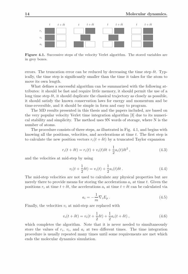
Figure 4.1. Successive steps of the velocity Verlet algorithm. The stored variables arein grey boxes.
errors. The truncation error can be reduced by decreasing the time step δt. Typ-ically, the time step is significantly smaller than the time it takes for the atom tomove its own length.
What defines a successful algorithm can be summarized with the following at-tributes: it should be fast and require little memory, it should permit the use of along time step δt, it should duplicate the classical trajectory as closely as possible,it should satisfy the known conservation laws for energy and momentum and betime-reversible, and it should be simple in form and easy to program.
The MD results presented in this thesis and the papers included, are based onthe very popular velocity Verlet time integration algorithm [3] due to its numeri-cal stability and simplicity. The method uses 9N words of storage, where N is thenumber of atoms.
The procedure consists of three steps, as illustrated in Fig. 4.1, and begins withknowing all the positions, velocities, and accelerations at time t. The first step isto calculate the new position vectors ri(t + δt) by a truncated Taylor expansion
ri(t + δt) = ri(t) + vi(t)δt +1
2ai(t)δt
2 , (4.3)
and the velocities at mid-step by using
vi(t +1
2δt) = vi(t) +
1
2ai(t)δt . (4.4)
The mid-step velocities are not used to calculate any physical properties but aremerely there to provide means for storing the accelerations ai at time t. Given thepositions ri at time t + δt, the accelerations ai at time t + δt can be calculated via
ai = − 1
m∇iEp . (4.5)
Finally, the velocities vi at mid-step are replaced with
vi(t + δt) = vi(t +1
2δt) +
1
2ai(t + δt) , (4.6)
which completes the algorithm. Note that it is never needed to simultaneouslystore the values of ri, vi, and ai at two different times. The time integrationprocedure is usually repeated many times until some requirements are met whichends the molecular dynamics simulation.

15
References.
[1] M. P. Allen and D. J. Tildesley, Computer Simulation of Liquids, OxfordUniversity Press, Inc. (1987).
[2] L. Rade and B. Westergren, Mathematics Handbook for Science andEngineering, Studentlitteratur, Inc. (1989).
[3] W. C. Swoope, H. C. Andersen, P. H. Berens, and K. R. Wilson, J. Chem.Phys. 76 (1982) 637.

16 Molecular dynamics.
CHAPTER 5
The embedded atom method.
The embedded atom method is a semi-empirical, pair-functional model for calcu-lating the cohesive energy of a metallic system. The success of the EAM sinceits formulation in 1983 by Daw and Baskes [1-2] is explained by the fact that itis much less complex than first-principles calculations but still manages to mimicthe coordination-dependent metallic bonding, and is not significantly more com-putationally demanding than pair potential schemes.
In the embedded-atom treatment, each atom is viewed as being embedded ina host lattice consisting of all other atoms. The fundamental concept is that theembedding energy for a particular species of atom is a unique function of the hostelectron density, independent of the source of that electron density. In addition,there is an energy from two-body electrostatic interactions. The ansatz for thecohesive energy for a set of atoms is
Ecoh =∑
i
Gi(ρi) +1
2
∑
i,j,i6=j
Uij(Rij) , (5.1)
with
ρi =∑
j( 6=i)
ρj(Rij) , (5.2)
where G is the embedding function, ρi is the electron density at atom i determinedby the densities from all other atoms j, U is the electrostatic two-body interaction,and Rij is the separation distance between atoms i and j. The embedding energyis defined as the interaction of the atom with the background electron gas. Thebackground gas at that atom is taken to be a linear superposition of sphericallyaveraged tail densities from all other atoms.
17
18 The embedded atom method.
5.1 Fundamentals.
The EAM format (eq. 5.1) can be derived from the density functional theory(DFT). This approach has been covered in depth by Daw [3] and what follows isa short summary of the process.
The cohesive energy Ecoh of a solid in terms of the electron density ρ withinthe DFT [4] is given by
Ecoh = G[ρ]+1
2
∑
i,j,i6=j
ZiZj
Rij−
∑
i
∫
Ziρ(r)
|r − Ri|dr+
1
2
∫ ∫
ρ(r1)ρ(r2)
|r1 − r2|dr1dr2−Eatoms,
(5.3)where the sums over i and j are over the nuclei of the solid, Z is the charge of anucleus, R is the position vector of a nucleus, and r is the position vector for theelectron density. The first term in the above equation represents the kinetic, ex-change, and correlation energy functional of the electrons. The second, third, andfourth terms represent the repulsive nucleus-nucleus, attractive electron-nucleus,and Coulombic electron-electron contributions, respectively. The last term is thetotal energy of the atoms at an infinite distance from each other.
Equation 5.1 can be obtained from 5.3 by making following two assumptions.First, it is assumed that the functional G[ρ] is semilocal
G[ρ] =
∫
g(ρ(r),∇ρ(r), . . .))dr (5.4)
which means that G can be divided into a sum of contributions from individualvolumes. Second, the electron density of the solid ρs(r) is approximated by alinear superposition of the densities of the individual atoms
ρs(r) =∑
i
ρai (r − Ri) . (5.5)
The first assumption is motivated by studies of the response function of the nearlyuniform electron gas [4]. The second assumption is justified if the covalent bondingin the metal is negligible [5]. The latter implies that the EAM is expected only tobe valid for simple metals and for early and late transition metals.
By rearranging eq. 5.3 and substituting ρ(r) with ρs(r) it can be written as
Ecoh = G[∑
i
ρai ] −
∑
i
G[ρai ] +
1
2
∑
i,j,i6=j
Uaij , (5.6)
where the first two terms represent the difference in kinetic, exchange, and corre-lation energies going from the case of isolated atoms to the solid. The last term isthe electrostatic energy of the overlaping charge distributions.
By considering a region around atom i, it is reasonable to assume that ρai dom-
inates and that the background density from the surrounding atoms in that regionis relatively small and slowly varying. Therefore, it seems plausible to approximatethe background density by a constant ρi.
5.2 Phenomenology. 19
The embedding energy for an atom in an electron gas of some constant density(neutralized by a positive background density) can thus be defined as
Gi(ρi) = G[ρai + ρi] − G[ρa
i ] − G[ρi] . (5.7)
By using the above defined embedding energy, the cohesive energy from eq. 5.6can be written as
Ecoh =∑
i
Gi(ρi) +1
2
∑
ij,i6=j
Uaij + Eerr , (5.8)
where the error is a function of the constant background density. Setting the errorto zero gives an equation for optimal ρi. In general, ρi is a functional of the truebackground density.
The difference between eqs. 5.3 and 5.8 is that the functional G[ρ] for the solidhas been reduced to evaluating the embedding function G(ρi) for each atom. Thisbecomes an advantage only if the constant background density is approximatedby
ρi =∑
j( 6=i)
ρaj (r − Rj) (5.9)
which, in turn, leads to that atomistic calculations become very straightforward.Note that since the embedding energy does not depend on the source of the
background density, same embedding functions can be used to evaluate the energyfor atoms in a homo-nuclear solid as well as in an alloy.
5.2 Phenomenology.
What makes the EAM so appealing is its physical picture of metallic bonding.The perspective where each atom is viewed as being embedded in a host electrongas created by its neighboring atoms provides the means for describing and un-derstanding the very important many-body interactions that are present in solids.In particular, it is simple to demonstrate how bonding is affected by coordinationZ.
It has been suggested [6] that the cohesive energy should scale something like−√
Z for metallic systems. Given the non-linearity for the cohesive energy and thatthe two-body electrostatic interactions are not coordination-dependent, the em-bedding function must be non-linear. This non-linearity reflects the bond strengthsaturation with increasing background density which, in turn, requires that thecurvature of the embedding function must be positive.
A way of realizing the presence of many-body interactions within the EAM isto examine the change in cohesive energy when making small perturbations from areference state. The basic approach is to replace G with a Taylor series expansionabout the unperturbed host electron density ρ. By choosing a uniform homonu-clear solid as the reference state, the cohesive energy for small distortions can be
20 The embedded atom method.
−1 0 1 2 3 4 5 6 7 8 9−1
−0.8
−0.6
−0.4
−0.2
0
Sca
led
pot
enti
alen
ergy
E
Scaled separation distance r
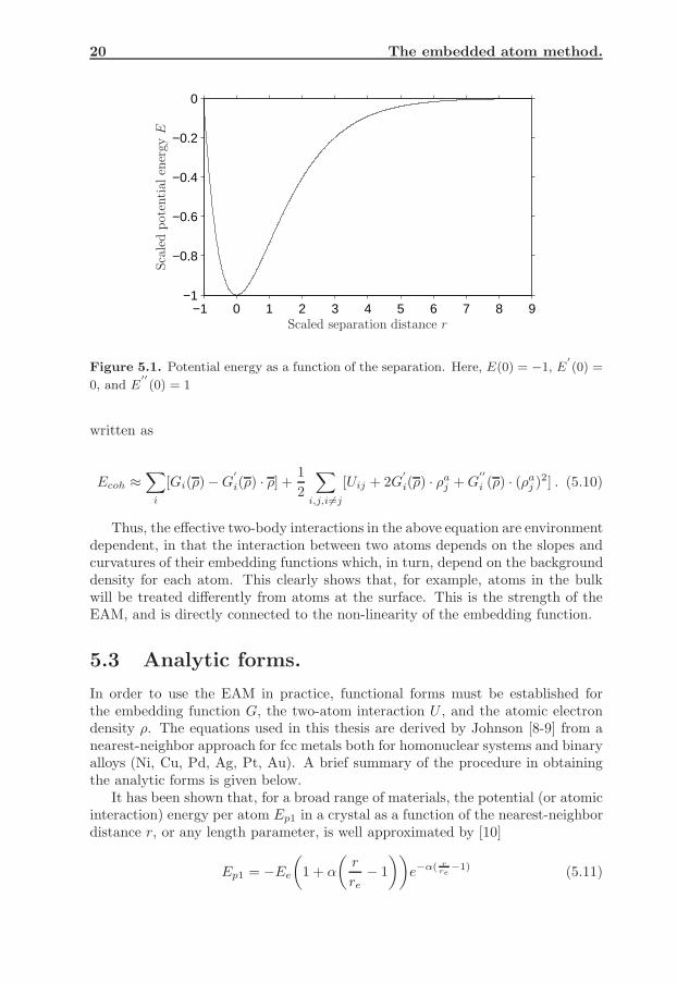
Figure 5.1. Potential energy as a function of the separation. Here, E(0) = −1, E′
(0) =
0, and E′′
(0) = 1
written as
Ecoh ≈∑
i
[Gi(ρ)− G′
i(ρ) · ρ] +1
2
∑
i,j,i6=j
[Uij + 2G′
i(ρ) · ρaj + G
′′
i (ρ) · (ρaj )2] . (5.10)
Thus, the effective two-body interactions in the above equation are environmentdependent, in that the interaction between two atoms depends on the slopes andcurvatures of their embedding functions which, in turn, depend on the backgrounddensity for each atom. This clearly shows that, for example, atoms in the bulkwill be treated differently from atoms at the surface. This is the strength of theEAM, and is directly connected to the non-linearity of the embedding function.
5.3 Analytic forms.
In order to use the EAM in practice, functional forms must be established forthe embedding function G, the two-atom interaction U , and the atomic electrondensity ρ. The equations used in this thesis are derived by Johnson [8-9] from anearest-neighbor approach for fcc metals both for homonuclear systems and binaryalloys (Ni, Cu, Pd, Ag, Pt, Au). A brief summary of the procedure in obtainingthe analytic forms is given below.
It has been shown that, for a broad range of materials, the potential (or atomicinteraction) energy per atom Ep1 in a crystal as a function of the nearest-neighbordistance r, or any length parameter, is well approximated by [10]
Ep1 = −Ee
(
1 + α
(
r
re− 1
))
e−α( r
re
−1) (5.11)
5.3 Analytic forms. 21
with
α = 3
(
ΩeBe
Ee
)
, (5.12)
where the subscript e is used to indicate evaluation at equilibrium, re is the nearest-neighbor distance, Ωe is the atomic volume, Be is the bulk modulus, and Ee is thecohesive energy. The functional behavior of eq. 5.11 is illustrated in Fig. 5.1.
While the EAM does not require the atomic interactions to be limited tonearest-neighbors only, it provides a very simple scheme in obtaining useful ana-lytic forms while retaining the first-order effects. Thus, for a perfect crystal thetwo-body interaction energy per atom as a function of the separation distance rcan be written as
Ua = 6U(r) , (5.13)
where U(r) represents the interaction between two atoms. Similarly, the back-ground electron density for each atom is then
ρa = 12ρ(r) , (5.14)
where ρ(r) is the tail density from one nearest-neighboring atom. By studyingthe sperically averaged free-atom charge densities calculated from Hartree-Focktheory for late transition metals [11-12], it can be seen that the density is wellapproximated by a single exponential term in the range of distances of interest inEAM calculations. Thus, the electronic density is taken as
ρ(r) = ρee−β( r
re
−1) , r ≤ rc . (5.15)
The two-body potential is taken as a Born-Mayer repulsion [13] in order to havethe same analytic form as ρ(r), i.e.
U(r) = Uee−γ( r
re
−1) , r ≤ rc , (5.16)
where rc is a cutoff parameter and β and γ are model parameters.The potential energy per atom in a perfect crystal from the EAM (nearest-
neighbor approximation) is
Ep1 = G(ρa) + Ua (5.17)
which in combination with eqs. 5.11, 5.15, and 5.16 leads to an expression for theembedding function G. Dropping the subscript a, the final form of G becomes
G(ρ) = −Ee
(
1 − α
βln
(
ρ
ρe
))(
ρ
ρe
)α/β
− 6Ue
(
ρ
ρe
)α/γ
. (5.18)
As seen, the embedding function is non-linear and when the electron densitygoes to zero so does G. The model parameters β, γ, ρe, and Ue are determinedvia a fitting procedure in which the lattice constant, cohesive energy, unrelaxedvacancy-formation energy, bulk modulus and Voigt-average shear modulus are used
22 The embedded atom method.
as input parameters to obtain the best fit [9]. The parameters given in [9] alsoyield a positive curvature of the embedding function.
The exact choice of the cutoff radius rc plays no significant role as long asit is well within the gap between first and second neighbors. In this thesis, theJohnson potential is replaced by a cubic spline in the interval ranging from 1.04 to1.5 of the nearest neighbor distance. The spline goes to zero at 1.5 of the nearestneighbor distance which is the interaction cutoff.
In the case of a binary alloy with atoms of type A and B, UAA and UBB aregiven by their respective model, while the two-body interaction between type Aand B is given by a weighted arithmetic mean
UAB(r) = UBA(r) =1
2
(
ρA(r)
ρB(r)UBB(r) +
ρB(r)
ρA(r)UAA(r)
)
. (5.19)
The above equation also imposes a criterion on the weighting factors, in that theelectron density for any of the alloy constituent cannot be zero at any distancefor which the two-body potential is non-zero. Therefore, a cutoff distance for thetwo-body potentials must be shorter than the interaction range for the densityfunctions.
Note that the analytic form is fitted to bulk solid properties and is thus ex-pected to work best for bulk calculations.
5.4 Applications.
The EAM has been applied to a large variety of problems related to bulk propertiesof late transition metals. A review of the various applications are summarized in[14] and show that calculations of, for example, bulk phonons, thermal expansioncoefficients, melting points, and point defects are in quite good agreement withexperimental values. In addition, metal surface properties such as surface energiesand relaxations have also been examined. Generally, the surface energies are sys-tematically too low, though the ordering with respect to face is correct. The errorin the absolute surface energy is due to neglecting the slope of the backgroundelectron density experienced by the surface atoms [3]. The interlayer spacings,calculated for relaxed surface geometries relative to the spacing in bulk geome-tries, show contraction between the top surface layer and the first sub-surfacelayer. Moreover, the rougher (110) surfaces demonstrate larger relaxations thanthe smoother (100) and (111) surfaces. Both of these general features agree withthe trends found in experimental data.
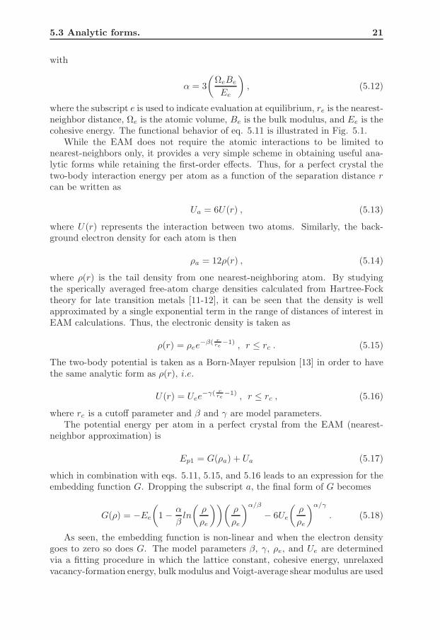
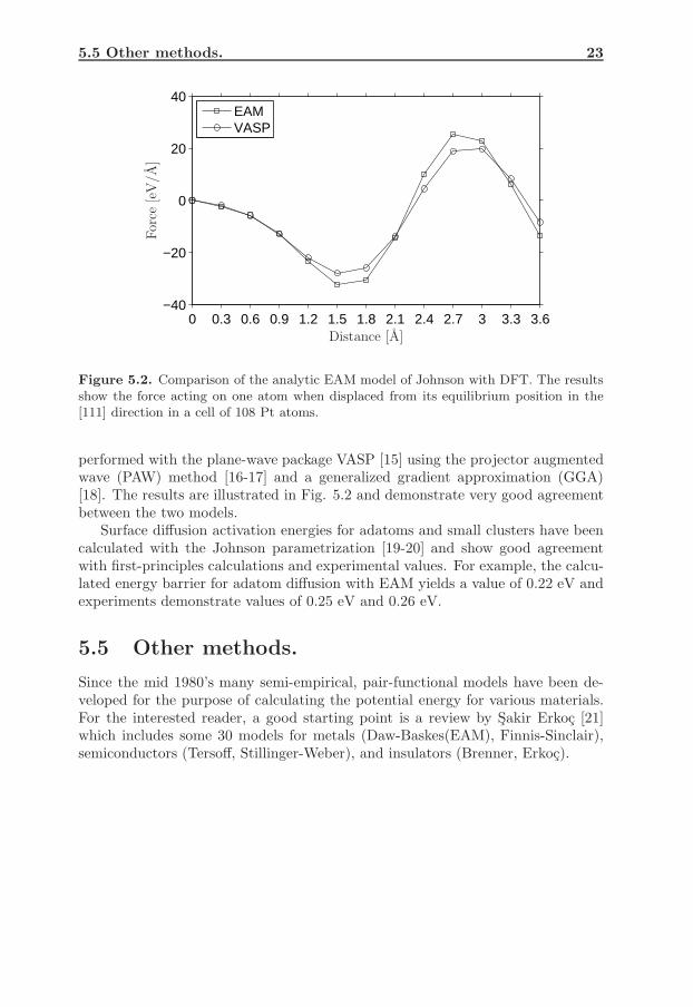
The analytic EAM model derived by Johnson [9] have been tested (by ourresearch group) by evaluating forces of displaced atoms in the bulk and energybarriers for surface diffusion. Comparisons with first-principles calculations andexperimental values have been made. For the bulk test, a cell of 108 Pt atomswas used. The atoms were initially at equilibrium positions. One atom was thendisplaced from the equilibrium position in the [111] direction in increments of 0.3A while keeping the remaining atoms fixed. The force acting on that atom wascalculated by using both EAM of Johnson and DFT. The DFT calculations were
5.5 Other methods. 23
0 0.3 0.6 0.9 1.2 1.5 1.8 2.1 2.4 2.7 3 3.3 3.6−40
−20
0
20
40
EAMVASP
For
ce[e
V/A
]
Distance [A]
Figure 5.2. Comparison of the analytic EAM model of Johnson with DFT. The resultsshow the force acting on one atom when displaced from its equilibrium position in the[111] direction in a cell of 108 Pt atoms.
performed with the plane-wave package VASP [15] using the projector augmentedwave (PAW) method [16-17] and a generalized gradient approximation (GGA)[18]. The results are illustrated in Fig. 5.2 and demonstrate very good agreementbetween the two models.
Surface diffusion activation energies for adatoms and small clusters have beencalculated with the Johnson parametrization [19-20] and show good agreementwith first-principles calculations and experimental values. For example, the calcu-lated energy barrier for adatom diffusion with EAM yields a value of 0.22 eV andexperiments demonstrate values of 0.25 eV and 0.26 eV.
5.5 Other methods.
Since the mid 1980’s many semi-empirical, pair-functional models have been de-veloped for the purpose of calculating the potential energy for various materials.For the interested reader, a good starting point is a review by Sakir Erkoc [21]which includes some 30 models for metals (Daw-Baskes(EAM), Finnis-Sinclair),semiconductors (Tersoff, Stillinger-Weber), and insulators (Brenner, Erkoc).

24
References.
[1] M. S. Daw and M. I. Baskes, Phys. Rev. Lett. 50 (1983) 1285.[2] M. S. Daw and M. I. Baskes, Phys. Rev. B 29 (1994) 6443.[3] M. S. Daw, Phys. Rev. B 39 (1989) 7441.[4] P. Hohenberg and W. Kohn, Phys. Rev. B 136 (1964) 864.[5] I. M. Torres, Interatomic Potentials, Academic Press, Inc. (1972).[6] A. Carlsson, H. Ehrenreich and D. Turnbull (Eds.), Solid State Physics,
Vol. 43, Academin Press, Inc. (1990).[7] S. M. Foiles, Phys. Rev. B 32 (1985) 3409.[8] R. A. Johnson, Phys. Rev. B 37 (1988) 3924.[9] R. A. Johnson, Phys. Rev. B 39 (1989) 12554.[10] J. H. Rose, J. R. Smith, F. Guinea, and J. Ferrante, Phys. Rev. B 29
(1984) 2963.[11] E. Clementi and C. Roetti, At. Data Nucl. Data Tables 14 (1974) 177.[12] A. D. McLean and R. S. McLean, At. Data Nucl. Data Tables 26
(1981) 197.[13] M. Born and J. E. Mayer, Z. Phys. 75 (1932) 1.[14] M. S. Daw, S. M. Foiles, and M. I. Baskes, Mat. Sci. Rep. 9 (1993) 251.[15] G. Kresse, and J. Furthmuller, Phys. Rev. B 54, (1996) 11169.[16] P. E. Blochl, Phys. Rev. B 50, (1994) 17953.[17] G. Kresse and D. Joubert, Phys. Rev. B 59, (1999) 1758.[18] J. P. Perdew, J. A. Chevary, S. H. Vosko, K. A. Jackson, M. R. Pederson,
D. J. Singh, and C. Fiolhais, Phys Rev. B 46, (1992) 6671.[19] E. P. Munger, V. Chirita, J. E. Greene, and J. -E. Sundgren, Surf. Sci.
355 (1996) L325.[20] E. P. Munger, V. Chirita, L. Hultman, and J. E. Greene, Surf. Sci. 539
(2003) L567.[21] S. Erkoc, Phys. Rep. 278 (1997) 79.
CHAPTER 6
Simulation experiments.
The purpose of this chapter is to give a brief summary of the results in the papersincluded. In common for all papers is that they focus on the intra- and interlayeratomistic patways as induced by normally incident Pt atoms on Pt(111) with ki-netic energies E ranging from 5 to 50 eV.
The MD program used to perform all simulation experiments was developedand written by Peter Munger (my supervisor). The program has been used inprevious MD studies with great success [1-11].
My contributions to the papers included are as follows. I performed the simu-lations. I conducted the analysis of the MD data. I compiled the results. I wrotethe first draft of each manuscript and was involved in all iterations until the finalversion.
6.1 Substrate specifics.
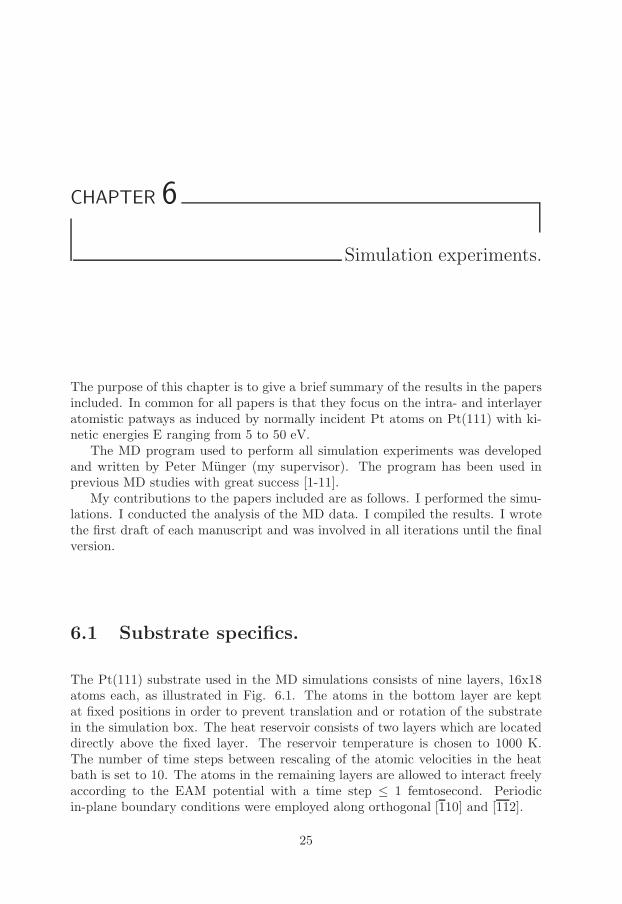
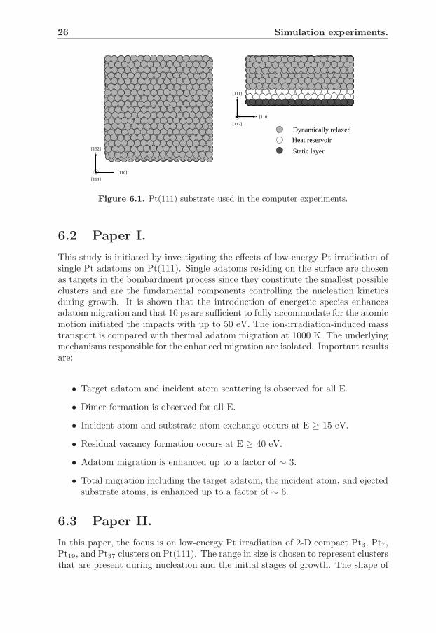
The Pt(111) substrate used in the MD simulations consists of nine layers, 16x18atoms each, as illustrated in Fig. 6.1. The atoms in the bottom layer are keptat fixed positions in order to prevent translation and or rotation of the substratein the simulation box. The heat reservoir consists of two layers which are locateddirectly above the fixed layer. The reservoir temperature is chosen to 1000 K.The number of time steps between rescaling of the atomic velocities in the heatbath is set to 10. The atoms in the remaining layers are allowed to interact freelyaccording to the EAM potential with a time step ≤ 1 femtosecond. Periodicin-plane boundary conditions were employed along orthogonal [110] and [112].
25
26 Simulation experiments.
[110]
[111]
[110]
[112]
[111]
[132] Static layer
Heat reservoir
Dynamically relaxed
Figure 6.1. Pt(111) substrate used in the computer experiments.
6.2 Paper I.
This study is initiated by investigating the effects of low-energy Pt irradiation ofsingle Pt adatoms on Pt(111). Single adatoms residing on the surface are chosenas targets in the bombardment process since they constitute the smallest possibleclusters and are the fundamental components controlling the nucleation kineticsduring growth. It is shown that the introduction of energetic species enhancesadatom migration and that 10 ps are sufficient to fully accommodate for the atomicmotion initiated the impacts with up to 50 eV. The ion-irradiation-induced masstransport is compared with thermal adatom migration at 1000 K. The underlyingmechanisms responsible for the enhanced migration are isolated. Important resultsare:
• Target adatom and incident atom scattering is observed for all E.
• Dimer formation is observed for all E.
• Incident atom and substrate atom exchange occurs at E ≥ 15 eV.
• Residual vacancy formation occurs at E ≥ 40 eV.
• Adatom migration is enhanced up to a factor of ∼ 3.
• Total migration including the target adatom, the incident atom, and ejectedsubstrate atoms, is enhanced up to a factor of ∼ 6.
6.3 Paper II.
In this paper, the focus is on low-energy Pt irradiation of 2-D compact Pt3, Pt7,Pt19, and Pt37 clusters on Pt(111). The range in size is chosen to represent clustersthat are present during nucleation and the initial stages of growth. The shape of
6.4 Paper III. 27
the target clusters (hexagonal starting with Pt7) are chosen since they correspondto the most energetically stable configurations on (111) planes.
The results are divided in three parts, intralayer effects, interlayer effects, anddefect formation. In common for all cases is that a few ps (< 10 ps) are sufficientfor the impact-induced processes to complete. The focus in the first part is on theintralayer effects where it is demonstrated that a rich variety of atomistic processescan be triggered during the bombardment process. Based upon visual inspection ofthe MD simulations, the overall results can be divided into three classes: clusterpreservation, cluster reconfiguration, and cluster disruption. Important resultsare:
• As E increases the island preservation probability decreases for all islandsizes.
• The overall preservation probability increases with island size.
• With E < 15 eV cluster reconfiguration is observed only to occur for Pt3and Pt7.
• With E ≥ 20 eV cluster disruption starts to occur.
The second part deals with interlayer events, specifically, the formation of 3-D is-lands. The results demonstrate four different energy-dependent mechanisms lead-ing to the transition from 2-D to 3-D islands. Important results are:
• Negligible probability for 3-D island formation involving Pt3.
• Decreasing 3-D island formation probability with increasing E for Pt7.
• For Pt19 and Pt37, the probability for 3-D island formation is ∼ 0.2 and 0.4,respectively, irrespective of E.
The third and last part deals with residual point defect formation, i.e. adatom/vacancypair formation events. Important results are:
• Point defects in clusters are only observed to occur for Pt19 and Pt37.
• A 3-D island is always created when a residual vacancy in a cluster is formed.
• Point defect formation is negligible up to E ∼ 30 eV.
6.4 Paper III.
With the knowledge basis obtained with papers I and II, paper III deals withlow-energy Pt irradiation on Pt(111) during homoepitaxy. Given that it is knownfrom experiments that low-energy ion irradiation is an effective tool for alteringthe growth from 3-D to 2-D mode in this energy range, the aim of this paper isto investigate the underlying mechanisms responsible for the transition in growthbehavior. In the simulations, 5 ML are deposited for each energy E with an
28 Simulation experiments.
arrival rate of 100 ps−1, for a total simulation time of 1 µs. This correspondsto a deposition rate of 5x10⁵ µs/mm, which is 103 times higher compared toexperimental conditions (electron beam-physical vapor deposition). At E = 25 eV,5 ML are deposited with an arrival rate of 1 ns−1, i.e. only 2 orders of magnitudehigher than experimental rates, for a total simulation time of 1 µs or 1.5 billiontime steps. Important results are:
• Ion-irraditiaion-induced mass transport is separated from thermal migrationduring growth, where the former is completed within 10 ps following theimpacts.
• The irradiation-induced mass transport is strongly dependent on the impactenergy.
• Thermal migration is essentially independent of deposition energy.
• With E ≥ 20 eV layer-by-layer growth is obtained and maintaned.
• The growth mode is determined solely by the atomistic processes in the first10 ps following the impacts and the energy level of the impacts.
• The same kinetic pathways, leading to an even more clear layer-by-layergrowth mode, are identified at fluxes approaching experimental conditions.
The MD simulation with the lower deposition rate took approximately 7 monthsto finish on a Intel Pentium 4 - 3.40 GHz.
Comment: In order to determine the growth mode, the specular anti-phaseintensity I, as would be measured in, for example, reflection high-energy electrondiffraction experiments, is calculated from the simulations as a function of time.The expression for the normalized anti-phase intensity is given by
I =[
∞∑
n=0
(−1)n(Θn − Θn+1)]2
, (6.1)
where Θn is the fractional coverage of the nth layer.
6.5 Paper IV.
This paper is built upon the same simulations as paper III, however, the focusis to give detailed information regarding the intra- and interlayer mass transportduring deposition as a function of the energy E. The results are divided in twoparts, interlayer and intralayer activity. In order to investigate the mass transportas induced by bombardment, the time between impacts is divided in two intervals,10 ps and 90 ps. The former represents bombardment-induced activity while thelatter corresponds to thermal migration. Important results are:
• Number of impacts generating interlayer events and the total displacementat each event is strongly correlated to incident energy E.
6.5 Paper IV. 29
• With E ≥ 20 eV, the net impact-induced interlayer mass transport is in theupward direction (towards the surface).
• The final distributions of the substrate and deposited atoms are stronglycorrelated to the impact energy E.
• Interlayer mixing with substrate surface atoms start to occur at E = 15 eV.
• Interlayer mixing with substrate sub-surface atoms start to occur at E = 30eV.
• Sputtering is observed with E ≥ 25 eV, reaching a value of less than 1% atE = 50 eV.
• The mass transport within a layer is strongly correlated to the layer coverage.
• Maximum intralayer migration within a layer occurs at a coverage of ∼ 0.05ML.
• The majority of the intralayer mass transport is generated by adatoms.
30
References.
[1] E. P. Munger, V. Chirita, J. E. Greene, and J. -E. Sundgren,Surf. Sci. 355 (1996) L325.
[2] M. H. Carlberg, V. Chirita, and E. P. Munger, Phys. Rev. B 54(1996) 2217.
[3] M. H. Carlberg, V. Chirita, and E. P. Munger, Nucl. Instrum.Methods Phys. Res. B 112 (1996) 109.
[4] M. H. Carlberg, V. Chirita, and E. P. Munger, Thin Solid Films317 (1998) 10.
[5] V. Chirita, E. P. Munger, J. -E. Sundgren, and J. E. Greene,Appl. Phys. Lett. 72 (1998) 127.
[6] E. P. Munger, V. Chirita, J. -E. Sundgren, and J. E. Greene,Thin Solid Films 318 (1998) 57.
[7] V.Chirita, E. P. Munger, J. E. Greene, and J. -E. Sundgren,Surf. Sci. 436 (1999) L641.
[8] M. H. Carlberg, E. P. Munger, and L. Hultman, J. Phys. Cond.Mat. 11 (1999) 6509.
[9] V. Chirita, E. P. Munger, J. E. Greene, and J. -E. Sundgren,Thin Solid Films 370 (2000) 179.
[10] M. H. Carlberg, E. P. Munger, and L. Hultman, J. Phys. Cond.Mat. 12 (2000) 79.
[11] E. P. Munger, V. Chirita, L. Hultman, and J. E. Greene, Surf.Sci. 539 (2003) L567.