moncalieri plant gt i t
TRANSCRIPT
M O N C A L I E R I P L A N T3RD G T
w w w . i r e n e n e r g i a . i t
Iren Energia is the company in the Iren Group whose core
businesses are the production and distribution of electri-
city, the production and distribution of thermal energy for
district heating and the provision of technological services.
Iren Energia constantly pursues its objectives, which are qua-
lity, reliability, sustainable development, energy efficiency
and a close relationship with the areas in which it operates.
The 3rd GT is part of the Moncalieri cogeneration plant, which,
together with the Torino Nord plant, supplies Turin’s district
heating system.
The plant is made up of two combined-cycle cogenera-
tion units (2nd GT and 3rd GT), with an overall electrical
capacity of 800 MW and thermal capacity of 520 MW in
cogeneration mode, and a 141 MW supplementary and
back-up plant.
The heat produced by the cogenerators provides district
heating for a total volume of 55 million cubic metres,
making Turin the city with the largest district heating sy-
stem in Italy.
Iren Energia S.p.A.Corso Svizzera, 9510143 Torino - ItalyTel. +39 011 5549 111Fax +39 011 53 83 13
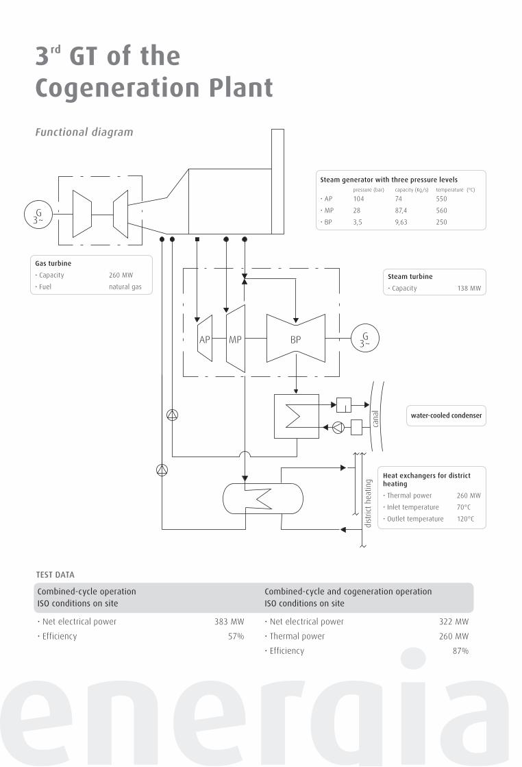
Combined-cycle operationISO conditions on site
• Net electrical power 383 MW
• Efficiency 57%
Combined-cycle and cogeneration operation ISO conditions on site
• Net electrical power 322 MW
• Thermal power 260 MW
• Efficiency 87%
TEST DATA
3rd GT of the Cogeneration Plant
G3~
GAP MP BP 3~
dist
rict
heat
ing
cana
l
Functional diagram
Steam generator with three pressure levels pressure (bar) capacity (Kg/s) temperature (°C)
• AP 104 74 550
• MP 28 87,4 560
• BP 3,5 9,63 250
Heat exchangers for district heating
• Thermal power 260 MW
• Inlet temperature 70°C
• Outlet temperature 120°C
Gas turbine
• Capacity 260 MW
• Fuel natural gas
Steam turbine
• Capacity 138 MW
water-cooled condenser
octo
ber
2013

M O N C A L I E R I P L A N T3RD G T
w w w . i r e n e n e r g i a . i t
Iren Energia is the company in the Iren Group whose core
businesses are the production and distribution of electri-
city, the production and distribution of thermal energy for
district heating and the provision of technological services.
Iren Energia constantly pursues its objectives, which are qua-
lity, reliability, sustainable development, energy efficiency
and a close relationship with the areas in which it operates.
The 3rd GT is part of the Moncalieri cogeneration plant, which,
together with the Torino Nord plant, supplies Turin’s district
heating system.
The plant is made up of two combined-cycle cogenera-
tion units (2nd GT and 3rd GT), with an overall electrical
capacity of 800 MW and thermal capacity of 520 MW in
cogeneration mode, and a 141 MW supplementary and
back-up plant.
The heat produced by the cogenerators provides district
heating for a total volume of 55 million cubic metres,
making Turin the city with the largest district heating sy-
stem in Italy.
Iren Energia S.p.A.Corso Svizzera, 9510143 Torino - ItalyTel. +39 011 5549 111Fax +39 011 53 83 13
Combined-cycle operationISO conditions on site
• Net electrical power 383 MW
• Efficiency 57%
Combined-cycle and cogeneration operation ISO conditions on site
• Net electrical power 322 MW
• Thermal power 260 MW
• Efficiency 87%
TEST DATA
3rd GT of the Cogeneration Plant
G3~
GAP MP BP 3~
dist
rict
heat
ing
cana
l
Functional diagram
Steam generator with three pressure levels pressure (bar) capacity (Kg/s) temperature (°C)
• AP 104 74 550
• MP 28 87,4 560
• BP 3,5 9,63 250
Heat exchangers for district heating
• Thermal power 260 MW
• Inlet temperature 70°C
• Outlet temperature 120°C
Gas turbine
• Capacity 260 MW
• Fuel natural gas
Steam turbine
• Capacity 138 MW
water-cooled condenser
octo
ber
2013
3rd GT of theCogeneration Plant
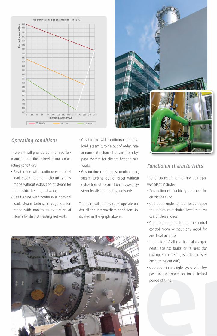
Operating conditions
The plant will provide optimum perfor-
mance under the following main ope-
rating conditions:
• Gas turbine with continuous nominal
load, steam turbine in electricity only
mode without extraction of steam for
the district heating network;
• Gas turbine with continuous nominal
load, steam turbine in cogeneration
mode with maximum extraction of
steam for district heating network;
• Gas turbine with continuous nominal
load, steam turbine out of order, ma-
ximum extraction of steam from by-
pass system for district heating net-
work;
• Gas turbine continuous nominal load,
steam turbine out of order without
extraction of steam from bypass sy-
stem for district heating network.
The plant will, in any case, operate un-
der all the intermediate conditions in-
dicated in the graph above.
Functional characteristics
The functions of the thermoelectric po-
wer plant include:
• Production of electricity and heat for
district heating;
• Operation under partial loads above
the minimum technical level to allow
use of these loads;
• Operation of the unit from the central
control room without any need for
any local actions;
• Protection of all mechanical compo-
nents against faults or failures (for
example, in case of gas turbine or ste-
am turbine cut-out);
• Operation in a single cycle with by-
pass to the condenser for a limited
period of time.
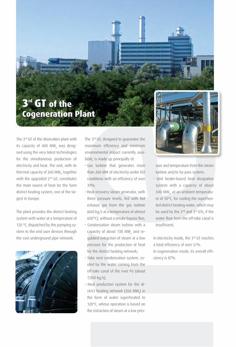
The 3rd GT of the Moncalieri plant with
its capacity of 400 MWe was desig-
ned using the very latest technologies
for the simultaneous production of
electricity and heat. The unit, with its
thermal capacity of 260 MWt, together
with the upgraded 2nd GT, constitutes
the main source of heat for the Turin
district heating system, one of the lar-
gest in Europe.
The plant provides the district heating
system with water at a temperature of
120 °C, dispatched by the pumping sy-
stem to the end user devices through
the vast underground pipe network.
The 3rd GT, designed to guarantee the
maximum efficiency and minimum
environmental impact currently avai-
lable, is made up principally of:
• Gas turbine that generates more
than 260 MW of electricity under ISO
conditions with an efficiency of over
39%;
• Heat recovery steam generator, with
three pressure levels, fed with hot
exhaust gas from the gas turbine
(660 kg/s at a temperature of almost
600°C), without a smoke bypass flue;
• Condensation steam turbine with a
capacity of about 138 MWe and re-
gulated extraction of steam at a low
pressure for the production of heat
for the district heating network;
• Tube nest condensation system, co-
oled by the water coming from the
off-take canal of the river Po (about
7,000 kg/s);
• Heat production system for the di-
strict heating network (260 MWt) in
the form of water superheated to
120°C, whose operation is based on
the extraction of steam at a low pres-
sure and temperature from the steam
turbine and/or by-pass system;
• Unit heater-based heat dissipation
system with a capacity of about
340 MWt, at an ambient temperatu-
re of 30°C, for cooling the superhea-
ted district heating water, which may
be used by the 2nd and 3rd GTs, if the
water flow from the off-take canal is
insufficient;
In electricity mode, the 3rd GT reaches
a total efficiency of over 57%.
In cogeneration mode, its overall effi-
ciency is 87%.
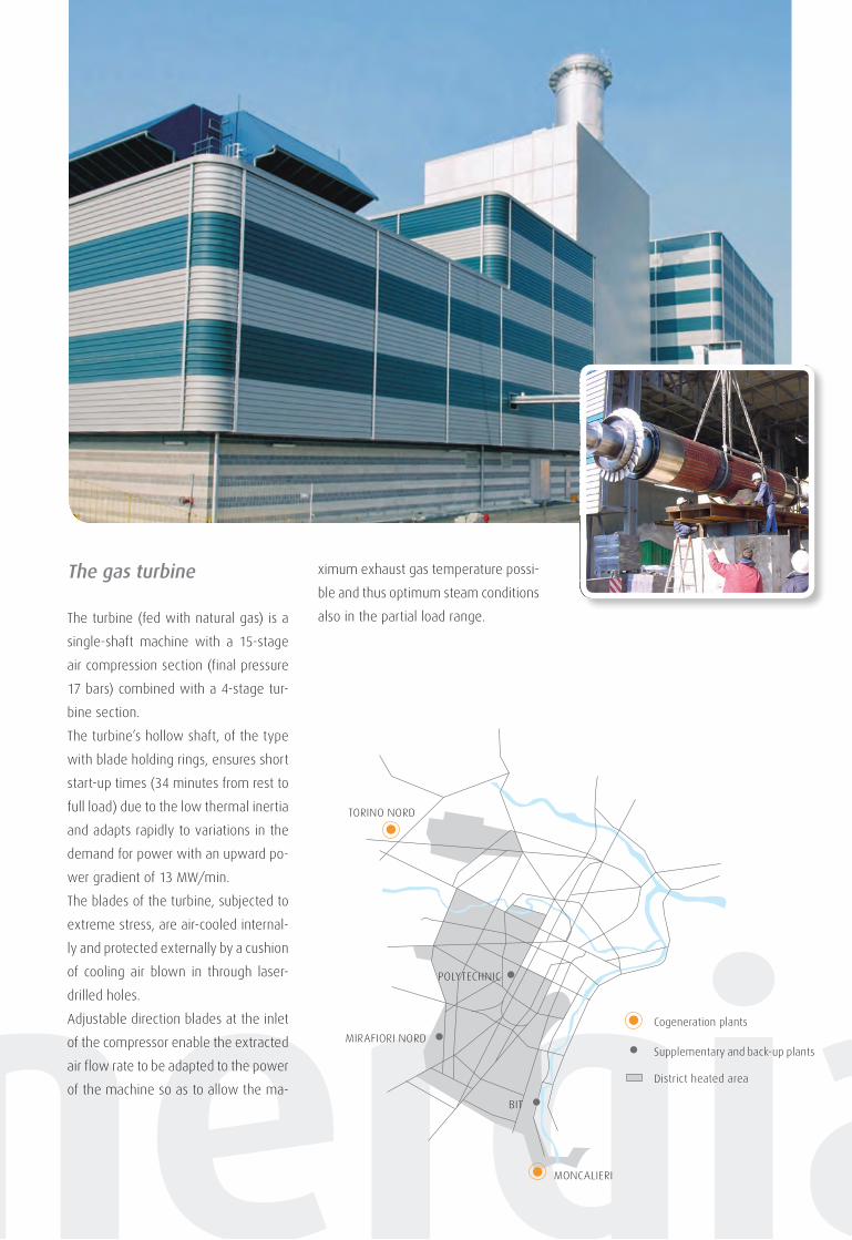
The gas turbine
The turbine (fed with natural gas) is a
single-shaft machine with a 15-stage
air compression section (final pressure
17 bars) combined with a 4-stage tur-
bine section.
The turbine’s hollow shaft, of the type
with blade holding rings, ensures short
start-up times (34 minutes from rest to
full load) due to the low thermal inertia
and adapts rapidly to variations in the
demand for power with an upward po-
wer gradient of 13 MW/min.
The blades of the turbine, subjected to
extreme stress, are air-cooled internal-
ly and protected externally by a cushion
of cooling air blown in through laser-
drilled holes.
Adjustable direction blades at the inlet
of the compressor enable the extracted
air flow rate to be adapted to the power
of the machine so as to allow the ma-
ximum exhaust gas temperature possi-
ble and thus optimum steam conditions
also in the partial load range.
The steam generator
The heat recovery steam generator
has the following characteristics:
• Three pressure levels;
• Degassing tower built into the cylin-
drical low-pressure body;
• High efficiency thermal design with
small-diameter tubes and tabs den-
sely arranged in a quincunx confor-
mation;
• Natural circulation, based on bro-
ad-diameter cylindrical bodies with
high-efficiency separators and high
circulation stability in the evapora-
tion circuits;
• “Hanging” support to allow free
downward expansion of the heat
exchange elements;
• Cold wall closure (insulated internal-
ly) with structure and reinforcements
welded externally;
• Fully welded pressurized parts;
• Completely drainable heat exchange
elements.
The steam turbine
The condensation steam turbine is
made up of separate high, medium
and low pressure turbine sections.
The high pressure turbine section has
a barrel-shaped body. The fixed sup-
port is situated between the HP and
MP turbine sections.
The LP turbine section has a dual-flow
design.
The internal casing of the LP section is
connected to the casing of the MP sec-
tion by connecting rods to reduce the
necessary play (thermal expansion).
The turbine blades provide three-di-
mensional flow optimization.
The HP and MP valves are compact,
combined valves (regulation and quick
stop valve form a unit). The steam
flows towards the bottom of the con-
denser situated below the turbine.
Steam for the district heating system
can be extracted from two steam
taps on the medium pressure turbi-
ne section.
390
380
370
360
350
340
330
320
310
300
290
280
270
260
250
240
230
220
210
200
190
1800 20 40 60 80 100 120 140 160 180 200 220 240 260
Thermal power (MW )
Elec
tric
al p
ower
(M
W ) e
t
TG 100% TG 75% TG 60%
Operating range at an ambient T of 15°C
Cogeneration plants
Supplementary and back-up plants
MONCALIERI
POLYTECHNIC
MIRAFIORI NORD
BIT
TORINO NORD
District heated area
3rd GT of theCogeneration Plant
Operating conditions
The plant will provide optimum perfor-
mance under the following main ope-
rating conditions:
• Gas turbine with continuous nominal
load, steam turbine in electricity only
mode without extraction of steam for
the district heating network;
• Gas turbine with continuous nominal
load, steam turbine in cogeneration
mode with maximum extraction of
steam for district heating network;
• Gas turbine with continuous nominal
load, steam turbine out of order, ma-
ximum extraction of steam from by-
pass system for district heating net-
work;
• Gas turbine continuous nominal load,
steam turbine out of order without
extraction of steam from bypass sy-
stem for district heating network.
The plant will, in any case, operate un-
der all the intermediate conditions in-
dicated in the graph above.
Functional characteristics
The functions of the thermoelectric po-
wer plant include:
• Production of electricity and heat for
district heating;
• Operation under partial loads above
the minimum technical level to allow
use of these loads;
• Operation of the unit from the central
control room without any need for
any local actions;
• Protection of all mechanical compo-
nents against faults or failures (for
example, in case of gas turbine or ste-
am turbine cut-out);
• Operation in a single cycle with by-
pass to the condenser for a limited
period of time.
The 3rd GT of the Moncalieri plant with
its capacity of 400 MWe was desig-
ned using the very latest technologies
for the simultaneous production of
electricity and heat. The unit, with its
thermal capacity of 260 MWt, together
with the upgraded 2nd GT, constitutes
the main source of heat for the Turin
district heating system, one of the lar-
gest in Europe.
The plant provides the district heating
system with water at a temperature of
120 °C, dispatched by the pumping sy-
stem to the end user devices through
the vast underground pipe network.
The 3rd GT, designed to guarantee the
maximum efficiency and minimum
environmental impact currently avai-
lable, is made up principally of:
• Gas turbine that generates more
than 260 MW of electricity under ISO
conditions with an efficiency of over
39%;
• Heat recovery steam generator, with
three pressure levels, fed with hot
exhaust gas from the gas turbine
(660 kg/s at a temperature of almost
600°C), without a smoke bypass flue;
• Condensation steam turbine with a
capacity of about 138 MWe and re-
gulated extraction of steam at a low
pressure for the production of heat
for the district heating network;
• Tube nest condensation system, co-
oled by the water coming from the
off-take canal of the river Po (about
7,000 kg/s);
• Heat production system for the di-
strict heating network (260 MWt) in
the form of water superheated to
120°C, whose operation is based on
the extraction of steam at a low pres-
sure and temperature from the steam
turbine and/or by-pass system;
• Unit heater-based heat dissipation
system with a capacity of about
340 MWt, at an ambient temperatu-
re of 30°C, for cooling the superhea-
ted district heating water, which may
be used by the 2nd and 3rd GTs, if the
water flow from the off-take canal is
insufficient;
In electricity mode, the 3rd GT reaches
a total efficiency of over 57%.
In cogeneration mode, its overall effi-
ciency is 87%.
The gas turbine
The turbine (fed with natural gas) is a
single-shaft machine with a 15-stage
air compression section (final pressure
17 bars) combined with a 4-stage tur-
bine section.
The turbine’s hollow shaft, of the type
with blade holding rings, ensures short
start-up times (34 minutes from rest to
full load) due to the low thermal inertia
and adapts rapidly to variations in the
demand for power with an upward po-
wer gradient of 13 MW/min.
The blades of the turbine, subjected to
extreme stress, are air-cooled internal-
ly and protected externally by a cushion
of cooling air blown in through laser-
drilled holes.
Adjustable direction blades at the inlet
of the compressor enable the extracted
air flow rate to be adapted to the power
of the machine so as to allow the ma-
ximum exhaust gas temperature possi-
ble and thus optimum steam conditions
also in the partial load range.
The steam generator
The heat recovery steam generator
has the following characteristics:
• Three pressure levels;
• Degassing tower built into the cylin-
drical low-pressure body;
• High efficiency thermal design with
small-diameter tubes and tabs den-
sely arranged in a quincunx confor-
mation;
• Natural circulation, based on bro-
ad-diameter cylindrical bodies with
high-efficiency separators and high
circulation stability in the evapora-
tion circuits;
• “Hanging” support to allow free
downward expansion of the heat
exchange elements;
• Cold wall closure (insulated internal-
ly) with structure and reinforcements
welded externally;
• Fully welded pressurized parts;
• Completely drainable heat exchange
elements.
The steam turbine
The condensation steam turbine is
made up of separate high, medium
and low pressure turbine sections.
The high pressure turbine section has
a barrel-shaped body. The fixed sup-
port is situated between the HP and
MP turbine sections.
The LP turbine section has a dual-flow
design.
The internal casing of the LP section is
connected to the casing of the MP sec-
tion by connecting rods to reduce the
necessary play (thermal expansion).
The turbine blades provide three-di-
mensional flow optimization.
The HP and MP valves are compact,
combined valves (regulation and quick
stop valve form a unit). The steam
flows towards the bottom of the con-
denser situated below the turbine.
Steam for the district heating system
can be extracted from two steam
taps on the medium pressure turbi-
ne section.
390
380
370
360
350
340
330
320
310
300
290
280
270
260
250
240
230
220
210
200
190
1800 20 40 60 80 100 120 140 160 180 200 220 240 260
Thermal power (MW )
Elec
tric
al p
ower
(M
W ) e
t
TG 100% TG 75% TG 60%
Operating range at an ambient T of 15°C
Cogeneration plants
Supplementary and back-up plants
MONCALIERI
POLYTECHNIC
MIRAFIORI NORD
BIT
TORINO NORD
District heated area

M O N C A L I E R I P L A N T3RD G T
w w w . i r e n e n e r g i a . i t
Iren Energia is the company in the Iren Group whose core
businesses are the production and distribution of electri-
city, the production and distribution of thermal energy for
district heating and the provision of technological services.
Iren Energia constantly pursues its objectives, which are qua-
lity, reliability, sustainable development, energy efficiency
and a close relationship with the areas in which it operates.
The 3rd GT is part of the Moncalieri cogeneration plant, which,
together with the Torino Nord plant, supplies Turin’s district
heating system.
The plant is made up of two combined-cycle cogenera-
tion units (2nd GT and 3rd GT), with an overall electrical
capacity of 800 MW and thermal capacity of 520 MW in
cogeneration mode, and a 141 MW supplementary and
back-up plant.
The heat produced by the cogenerators provides district
heating for a total volume of 55 million cubic metres,
making Turin the city with the largest district heating sy-
stem in Italy.
Iren Energia S.p.A.Corso Svizzera, 9510143 Torino - ItalyTel. +39 011 5549 111Fax +39 011 53 83 13
Combined-cycle operationISO conditions on site
• Net electrical power 383 MW
• Efficiency 57%
Combined-cycle and cogeneration operation ISO conditions on site
• Net electrical power 322 MW
• Thermal power 260 MW
• Efficiency 87%
TEST DATA
3rd GT of the Cogeneration Plant
G3~
GAP MP BP 3~
dist
rict
heat
ing
cana
l
Functional diagram
Steam generator with three pressure levels pressure (bar) capacity (Kg/s) temperature (°C)
• AP 104 74 550
• MP 28 87,4 560
• BP 3,5 9,63 250
Heat exchangers for district heating
• Thermal power 260 MW
• Inlet temperature 70°C
• Outlet temperature 120°C
Gas turbine
• Capacity 260 MW
• Fuel natural gas
Steam turbine
• Capacity 138 MW
water-cooled condenser
octo
ber
2013