monitoring fugitive emissions per epa draft method 325 … · monitoring fugitive emissions per epa...
TRANSCRIPT

Monitoring fugitive emissions per EPA Draft Method 325 and ozone precursors via PAMS networks
Agilent technologies, Inc.
June 2015

Indoor air quality and
tracer gases used for
ventilation studies
Landfill gas monitoring
Biogenic
emissions
Odorous industrial emissions
Hydraulic
Fracturing
Air Monitoring Applications Include:
Atmospheric Research
In situ monitoring of underground
contamination
ambient air monitoring

Refinery Perimeter Monitoring per EPA Method 325 (Draft)
Passive Sampling with
VOC Analysis by
TD/GC/MS

Refinery Perimeter Monitoring New Regulation Requirements
Continuous monitoring of vapor phase organics (VOCs)
around the perimeter of oil refineries
• Planned implementation in mid-2015
• Operators will be given 3 years to comply
US EPA Methods 325 A and 325 B drafted for compliance
• Final comment period closes at end of October 2014
• Method 325 specifies 2-week passive sampling using sorbent
tubes. Pumped monitoring onto sorbent tubes may also be allowed.
• Analysis by TD/GC/MS (FID allowed, MS recommended)

Target Compounds Refinery Perimeter Monitoring
Target compounds include:
• Benzene
• Any of the 97 VOCs that EPA has classed as hazardous air
pollutants (HAPs)
• Other VOCs present in refinery air
• For example, light- and middle-distillate fuel
components

Why passive sampling using sorbent tubes?
• Well validated for ambient air – ISO 16017-2, ASTM D6196, EN
14662-4
• Robust – Variable ambient conditions (temperature, wind speed,
humidity, interferences) have minimal impact on uptake rate
• Low cost – Samplers are re-usable >50 times and are inexpensive
to buy and transport
• Versatile – Sorbent tubes can be used for
pumped or passive sampling and offer
quantitative sampling & release of
compounds over a wide volatility range.
For passive sampling a diffusion cap
is fitted to the sampling end of the
tube, while the other end is kept
sealed

Monitoring Industrial Air Using Passive Sorbent Tubes
Passive (diffusive) samplers
are deployed around the
perimeter of refineries and
other petrochemical plants
under weather proof hoods.
(Reproduced with permission from BP)
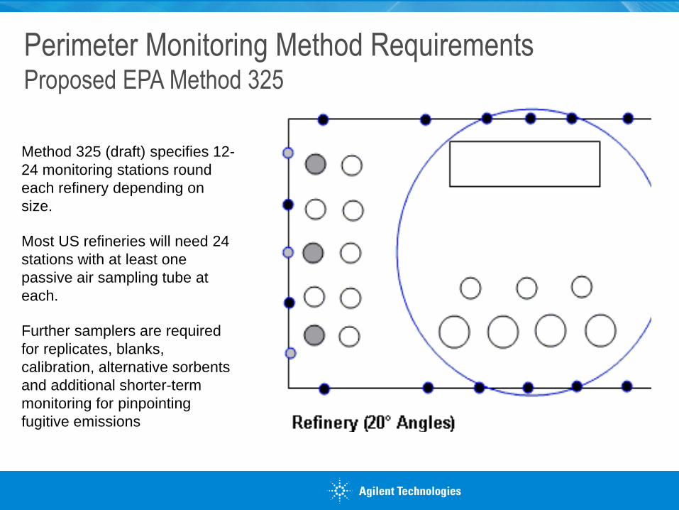
Method 325 (draft) specifies 12-
24 monitoring stations round
each refinery depending on
size.
Most US refineries will need 24
stations with at least one
passive air sampling tube at
each.
Further samplers are required
for replicates, blanks,
calibration, alternative sorbents
and additional shorter-term
monitoring for pinpointing
fugitive emissions
Perimeter Monitoring Method Requirements Proposed EPA Method 325

Long-term passive sampling of ambient and industrial air
2-week passive sampling of light hydrocarbons monitored around the perimeter
of a major petrochemical installation
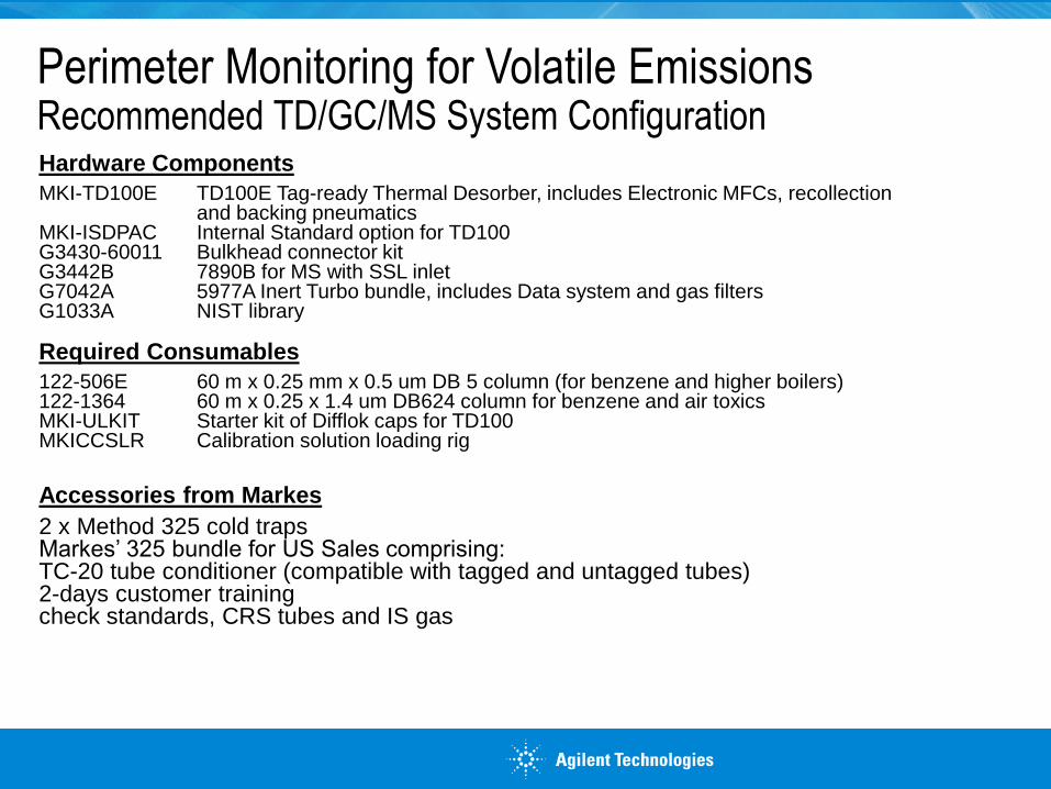
Perimeter Monitoring for Volatile Emissions Recommended TD/GC/MS System Configuration
Hardware Components
MKI-TD100E TD100E Tag-ready Thermal Desorber, includes Electronic MFCs, recollection and backing pneumatics MKI-ISDPAC Internal Standard option for TD100 G3430-60011 Bulkhead connector kit G3442B 7890B for MS with SSL inlet G7042A 5977A Inert Turbo bundle, includes Data system and gas filters G1033A NIST library Required Consumables
122-506E 60 m x 0.25 mm x 0.5 um DB 5 column (for benzene and higher boilers) 122-1364 60 m x 0.25 x 1.4 um DB624 column for benzene and air toxics MKI-ULKIT Starter kit of Difflok caps for TD100 MKICCSLR Calibration solution loading rig
Accessories from Markes
2 x Method 325 cold traps Markes’ 325 bundle for US Sales comprising: TC-20 tube conditioner (compatible with tagged and untagged tubes) 2-days customer training check standards, CRS tubes and IS gas

Tube shelters for each refinery perimeter monitoring point
Field monitoring kits comprising:
Conditioned capped and tagged sorbent tubes
Diffusion caps
Convenient sampling tools
Tag read/write tools
Note: Continuous 14-day monitoring is required so 3 sets of samplers will
normally be needed: One in use in the field, one in the lab being analysed
and a third set ready for deployment
Perimeter Monitoring for Volatile Emissions Sampling equipment required
6/24/2015
Monitoring Refinery Perimeters for VOC Emissions
11
• Oil Refiners (~140 US Refinery Locations)
• Associated contract laboratories (environmental,
petrochemical services)
• Federal and state regulators
• Any other petrochemical operations faced with longer
term impact
Perimeter Monitoring for Volatile Emissions

Analytical system provides the following unique
advantages:
1. Quantitative sample re-collection for repeat analysis -
recommended for validation of analyte recovery
2. 100-tube capacity - optimises productivity
3. TubeTAG - RFID tube tags track tubes from field to lab and
record the history of each sampler. Recommended for
reliable audit trail and chain-of custody
4. Reliability - TD-100 system operates cryogen-free and
provides full compliance with key national and international
standard methods
Perimeter Monitoring for Volatile Emissions Key Performance Advantages

Agilent’s partners at Markes pioneered automatic
quantitative sample re-collection of TD samples
(SecureTD-Q)
Quantitative re-collection of TD samples offers the
following key capabilities
• Repeat analysis under the same conditions for
confirmation of data and method validation
• Repeat analysis using a different analytical system
• Sample archiving
Advantage #1: Recollection for Repeat Analysis A Breakthrough in Thermal Desorption

• Inert heated, low volume valve allows
quantitative recovery of high & low volatility
compounds plus reactive species
• It also isolates the TD system allowing
compliance with standard methods: leak testing,
backflush trap desorption, purge to vent, overlap
mode, etc.
Heated valve
To GC
Time
Inte
nsity
During stage 1 trapped analytes are
desorbed from the heated sample
tube and transferred to the
electrically-cooled focusing trap
Principles of Operation Recollection for Repeat Analysis, Stage 1
Heated valve
To GC
Time
Inte
nsity
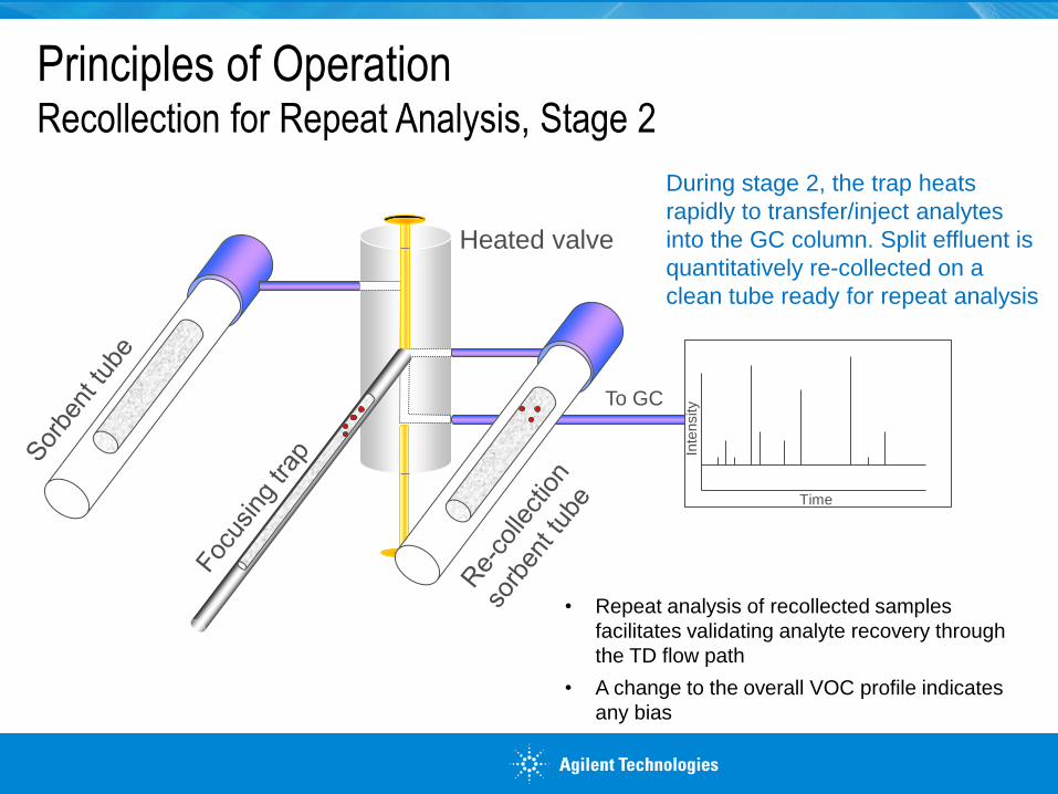
• Repeat analysis of recollected samples
facilitates validating analyte recovery through
the TD flow path
• A change to the overall VOC profile indicates
any bias
During stage 2, the trap heats
rapidly to transfer/inject analytes
into the GC column. Split effluent is
quantitatively re-collected on a
clean tube ready for repeat analysis
Principles of Operation Recollection for Repeat Analysis, Stage 2

With a compact arrangement of up to 10 trays, each housing up to 10 tagged or untagged
tubes, TD-100 can accommodate up to 100 sorbent tubes
This can comprise:
- 100 sample tubes, or…
- 50 sample tubes and 50 re-collection tubes
With 40 minute GC cycle times a fully loaded TD-100 can operate unattended all weekend
Another unique advantage of TD-100 is the patented
tube capping arrangement… Tubes are kept capped
and sealed at all times while on the TD-100 – before,
during and after operation. This prevents analyte losses
and ingress of lab air contaminants, without
complicating mechanical operation
Advantage #2: TD-100 has capacity for 100 tubes
DiffLok caps remain on sorbent
tubes throughout automatic
thermal desorption

All tubes are labelled with a unique ID number
in barcode and alphanumeric format, standard.
- They can also be RFID-tagged
Tags allow history to be tracked throughout
tube life: sorbent type, date of packing, number
of analytical cycles, etc.
Tags can also be programmed with sample-
specific data, such as, sampling start
time/date, sampling end time/date, and
sampling location
Tag read/write functions standard feature of the
TD-100
Advantage #3: TubeTAGTM Unique Innovation for TD
Note: tube tagging is optional not mandatory on TD-100

1. Tag permanently attached to tube & programmed
with tube-related information using TAGSCRIBE
2. Tagged tube sent
to field. Sample
details written to tag
via TAGSCRIBE
3. Tagged tube returned to lab and data
retrieved using automated tag r/w on TD
instrument
4. Tube analysed on TD system.
Tag(s) automatically updated with
relevant info. Tagged tube ready for
re-use
RFID tagging offers
enhanced traceability
for optimum chain-
of-custody
TubeTAGTM Theory of Operation

Tube Information
Sample location
Sorbent packing
# analytical cycles
Tube status
Access to
sample info
in the field
Sample Information
Access to tube &
sample info via
TD-100 in lab
Sample start info Sample end info “TubeTAG is a genuine breakthrough in TD technology. It allows users to monitor the history of each individual tube and track samples from field to lab.”
Information Stored on TubeTAG

Use of tagged tubes enhances automated re-
collection for repeat analysis
When tagged tubes are used, sample information is
automatically transferred to the tag of the re-
collection tube creating an audit trail
Automated TD re-collection using a single TD autosampler is proprietary.
Patents: GB 2395785 & US 6,446,515 B2
On-board TAG Read/Write and Recollection
TD-100 Thermal Desorber

• With barcode technology it is difficult to guarantee continued legibility as
tubes are subjected to high desorption temperatures and ambient
weather conditions. If you can’t read the barcode, you cannot read the
data!
• Who creates and maintains the tube database? The environmental lab?
The field monitoring contractor? The site owners? If you can’t rely on a
well maintained database, barcodes can’t be used to track tube history or
sample information.
− With tags, the information stays with the tube and can be accessed at any
time via TAGScribe or TD-100
• Barcodes are difficult / impossible to read automatically during TD-GCMS
analysis. This means bar codes can’t be used to track a sample through a
sequence of re-collections and repeat analysis
Advantages of TubeTAG versus bar codes

PAMS Program: Monitoring Ozone Precursors
Agilent technologies, Inc.
June 2015

Online sampling applications
Ambient Air
Zero Air
Standard
Gas
A three sample channel system can be used to alternate between
sample, standard and blank gases facilitating automatic calibration
and unattended operation of the system.

Where to monitor?
Ozone precursor (O3P) stations are carefully located according to
meteorology, topography, and relative proximity to emissions sources of
VOC and NOx.
Each O3P network generally consists of four different monitoring sites
(Types 1, 2, 3, and 4) designed to fulfill unique data collection objectives.
Type 1
Type 2
Type 3 Type 4

Quantitative Retention of
Acetylene from 1500 mL of
Air without Liquid Cryogen
Plot of peak area against volume
sampled for acetylene
(courtesy Ecole des Mines de Douai)
Key:
Blue (3 am)
Red (12 noon)
Green (5.30 pm)
Ethane
Ethene
Acetylene
Propane Propene
2-methylpropene
Butane
1-Butene
Pentane
Sequence of Analyses of Ozone
Precursors in Suburban Air Using a
Single Column Splitless analysis of 500 mL of ambient air
Performance of the system

Click to edit Master title style
Deans Switch Switch
effluent to
Second
Column
Deans
Switch
7890A GC
FID1 FID2
Column 1 Column 2
Capillary Flow Technology
UNITY -
Air Server

Column 1
Mid point pressure
17 psi
Sample in
38 psi
Polydimethylsiloxane
(Pre-column)
PLOT AL2O3/Na2SO4
(Column 2)
Deactivated silica (Column 1)
FID 1 FID 2
Dual-column, dual-FID, System for Optimum
Ozone Precursor Analysis

Column 2
Mid point pressure
17 psi
Sample in
38 psi
Polydimethylsiloxane
(Pre-column)
PLOT AL2O3/Na2SO4
(Column 2)
Deactivated silica (Column 1)
FID 1 FID 2
Dual-column, dual-FID, System for Optimum
Ozone Precursor Analysis

Application: Monitoring of C2-C10 hydrocarbons (ozone precursors) in ambient air (TD-GC dual FID)
• Target compounds:
- C2 to C10 Hydrocarbons (Ozone
Precursors)
- ‘Ozone Precursors’ focusing trap
used at -30ºC, flow path at 120⁰C
• Performance in field operation:
- Detection limits: <0.05 ppb
- Retention time stability: <0.2% RSD
across all compounds
- Standard reproducibility: 0.2-5%
RSD
- Excellent peak shape for splitless
injection
DB-1 Column showing
retention of C7 to C9
PLOT Column
showing retention of
C2 to C6 compounds

Repeat Analyses of Ozone Precursor Gas
Standard by UNITY-Air Server - GC-FID (Dual
column)
Volume of standard Range of RSD’s
250 mL 0.2 to 5.5
375 mL 0.3 to 2.9
500 mL 0.2 to 4.3
625 mL 0.3 to 3.5
750 mL 0.3 to 3.2
C2–C3 hydrocarbons:
Detection: 0.05 ppb; quantification: 0.1 ppb
C4+ hydrocarbons:
Detection: 0.03 ppb; quantification: 0.06 ppb
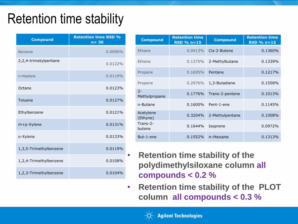
Retention time stability
Compound Retention time RSD %
n= 30
Benzene 0.0090%
2,2,4-trimetylpentane
0.0122%
n-Heptane 0.0119%
Octane 0.0123%
Toluene 0.0127%
Ethylbenzene 0.0121%
m+p-Xylene 0.0131%
o-Xylene 0.0133%
1,3,5-Trimethylbenzene 0.0119%
1,2,4-Trimethylbenzene 0.0108%
1,2,3-Trimethylbenzene 0.0104%
Compound Retention time
RSD % n=15 Compound
Retention time
RSD % n=15
Ethane 0.0413% Cis-2-Butene 0.1360%
Ethene 0.1375% 2-Methylbutane 0.1339%
Propane 0.1695% Pentane 0.1217%
Propene 0.2976% 1,3-Butadiene 0.1558%
2-
Methylpropane 0.1776% Trans-2-pentene 0.1013%
n-Butane 0.1600% Pent-1-ene 0.1145%
Acetylene
(Ethyne) 0.3204% 2-Methylpentane 0.1008%
Trans-2-
butene 0.1644% Isoprene 0.0972%
But-1-ene 0.1552% n-Hexane 0.1313%
• Retention time stability of the
polydimethylsiloxane column all
compounds < 0.2 %
• Retention time stability of the PLOT
column all compounds < 0.3 %
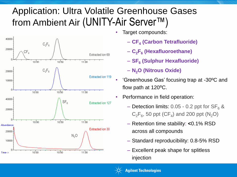
Application: Ultra Volatile Greenhouse Gases
from Ambient Air (UNITY-Air Server™)
Extracted ion 69
Extracted ion 119
Extracted ion 127
Extracted ion 30
CF4
C2F6
C2F6
SF6
N2O
• Target compounds:
‒ CF4 (Carbon Tetrafluoride)
‒ C2F6 (Hexafluoroethane)
‒ SF6 (Sulphur Hexafluoride)
‒ N2O (Nitrous Oxide)
• ‘Greenhouse Gas’ focusing trap at -30ºC and
flow path at 120⁰C.
• Performance in field operation:
‒ Detection limits: 0.05 - 0.2 ppt for SF6 &
C2F6, 50 ppt (CF4) and 200 ppt (N2O)
‒ Retention time stability: <0.1% RSD
across all compounds
‒ Standard reproducibility: 0.8-5% RSD
‒ Excellent peak shape for splitless
injection

Thank you Let’s Continue the Conversation