monitoring systems for coal mines utilizing booster …
TRANSCRIPT
MONITORING SYSTEMS FOR COAL MINES
UTILIZING BOOSTER FANS
by
Vasu Gangrade
A thesis submitted to the faculty of The University of Utah
in partial fulfillment of the requirements for the degree of
Master of Science
Department of Mining Engineering
The University of Utah
August 2014

Copyright © Vasu Gangrade 2014
All Rights Reserved

T h e U n i v e r s i t y o f U t a h G r a d u a t e S c h o o l
STATEMENT OF THESIS APPROVAL
The thesis of Vasu Gangrade
has been approved by the following supervisory committee members:
Felipe Calizaya , Chair 05/14/2014
Date Approved
Michael G. Nelson , Member 05/14/2014
Date Approved
Kevin Perry , Member 05/14/2014
Date Approved
and by Michael G. Nelson , Chair/Dean of
the Department/College/School of Mining Engineering
and by David B. Kieda, Dean of The Graduate School.

ABSTRACT
A booster fan is an underground ventilation device installed in series with a main
surface fan and is used to boost the pressure of air of the current passing through it.
Currently, federal regulations in the U.S. do not permit the use of booster fans in
underground bituminous and lignite coal mines. Considering that a booster fan is an
active device with moving parts, it is imperative to install it with an efficient and
reliable monitoring and control system. The important aspects of booster fans and
monitoring systems that are discussed in this thesis are environmental monitoring,
condition monitoring, design and installation principles, guidelines for safe operation of
booster fans, fan interlocking, and risk assessment.
The environmental status of underground mining operations with large booster fans
is critical to the health and safety of the miners. Mining operations, especially in large
deep coal mines, rely greatly upon the monitoring systems to create safe and healthy
work conditions by monitoring carbon monoxide, methane, carbon dioxide, oxygen,
nitrogen oxides, and smoke.
Condition monitoring is the process of measuring the fan operating factors to
evaluate and predict the health of mining machinery. In coal mine ventilation, condition
monitoring includes the measurement and evaluation of the following factors: vibration,
barometric pressure, noise, input power, motor and bearing temperatures, differential

iv
pressures, and air flow rate.
The monitoring system network in a mine could become extremely complex if the
monitors are not located at the right place. Recommendations are given for calculating
the appropriate siting and spacing of monitors.
Booster fans are assembled and installed to operate under harsh conditions; they are
subject to wear and tear and malfunction. Installation principles are discussed in detail
and recommendations are made for the safe operation of booster fans. Interlocking is
one method of preventing the occurrence of unsafe conditions due to electrical or
mechanical failures. It is described in detail, and the best practices used in other coal
mining countries are summarized. To ensure the safe operation of booster fans and
monitoring systems underground, a risk assessment was done, critical hazards were
identified, and mitigation controls are outlined.

TABLE OF CONTENTS
ABSTRACT .................................................................................................................... iii
LIST OF TABLES .......................................................................................................... vii
LIST OF FIGURES ....................................................................................................... viii
ACKNOWLEDGEMENTS .............................................................................................. x
Chapters
1 INTRODUCTION ................................................................................................ 1
1.1 Problem Statements ........................................................................................ 3 1.2 Thesis Objectives and Scope of Work ............................................................ 7
2 BOOSTER FAN SYSTEMS ................................................................................ 9
2.1 History of Booster Fans in the U.S. ................................................................ 9 2.2 Basic Requirements ...................................................................................... 10 2.3 Fan Monitoring and Control System ............................................................ 11 2.4 Advantages and Disadvantages .................................................................... 13 2.5 Recirculation ................................................................................................. 15
3 MINE VENTILATION FORMULAE ............................................................... 20
3.1 Fluid Flow Principles .................................................................................... 203.2 Airflow Resistance ........................................................................................ 23 3.3 Leakage Flow ................................................................................................ 25 3.4 Fan Pressure .................................................................................................. 27 3.5 Recirculation ................................................................................................. 28 3.6 Methane Layering ......................................................................................... 29
4 ATMOSPHERIC MONITORING SYSTEMS .................................................. 34
4.1 Terminology ................................................................................................. 35

vi
4.2 Transmission of Data .................................................................................... 36 4.3 Implementation of AMS in the U.S. ............................................................. 39 4.4 Environmental Monitoring ........................................................................... 40 4.5 Condition Monitoring ................................................................................... 48 4.6 Design of AMS ............................................................................................. 63 4.7 AMS Operator Training ................................................................................ 67
5 BOOSTER FAN MONITORING SYSTEMS ................................................... 77
5.1 Introduction ................................................................................................... 78 5.2 Design and Installation Principles ................................................................ 81 5.3 Basic Monitoring Requirements in Coal Mines ........................................... 83 5.4 Number, Location, and Type of Monitors .................................................... 91 5.5 Fan Interlocking System ............................................................................... 94 5.6 Uninterruptible Power Supply ...................................................................... 97 5.7 Risk Assessment of Monitoring Systems ..................................................... 98
6 CONCLUSIONS AND DISCUSSIONS .......................................................... 111
6.1 Conclusions................................................................................................. 111 6.2 Discussions ................................................................................................. 114
Appendices
A: GAS SENSING METHODS ................................................................................... 119
B: SUMMARY OF FEDERAL REGULATIONS ....................................................... 124
C: GUIDELINES FOR SPACING OF MONITORS ................................................... 132
REFERENCES ............................................................................................................. 138
LIST OF TABLES
4.1 Parameters monitored by AMS .......................................................................... 71
4.2 Classification of mine gases ............................................................................... 72
5.1 Use of booster fan in U.K. and Australian coal mines—comparative analysis ............................................................................................................. 103
5.2 Risk matrix ........................................................................................................ 108
5.3 WRAC analysis and outcomes ......................................................................... 109
C.1 Production constants for coal and wood ........................................................... 135

LIST OF FIGURES
2.1 Schematic showing booster fan installation ....................................................... 18
2.2 Schematic of an atmospheric monitoring system (AMS) installation ................ 18
2.3 Types of controlled recirculation ........................................................................ 19
3.1 Example of ventilation system to demonstrate pressure losses in a mine .......... 32
3.2 Basic layout of face or district ventilation flow quantities ................................. 33
4.1 Schematic of an AMS installation in mine ......................................................... 70
4.2 Measuring vibration using a vibrometer ............................................................. 73
4.3 Vibration severity chart ...................................................................................... 73
4.4 Fan pressure vs. barometric pressure measured in Salt Lake City ..................... 74
4.5 Measure of velocity at an underground booster fan ........................................... 75
4.6 Schematic showing the operating principle of an ultrasonic anemometer ........ 75
4.7 Lateral placement of sensor in belt entry ............................................................ 76
5.1 Installation of booster fans in Australian coal mines ........................................ 102
5.2 Installation of booster fan in U.K. coal mines .................................................. 102
5.3 Booster fan installation in the roof (section view) ............................................ 105
5.4 Shotcreting near the booster fan installation .................................................... 105
5.5 Conceptual design of booster fan installation and monitoring system ............. 106
5.6 Location of monitor for air flow measurement ................................................. 106

ix
5.7 Schematic of interlocking system ..................................................................... 107
5.8 Bow-tie analysis chart ....................................................................................... 110
B.1 Location of CO sensor where air splits ............................................................. 128
B.2 Sensor spacing—air from belt entry is not used to ventilate working sections 129
B.3 Sensor spacing—air from belt entry is used to ventilate working sections ...... 129
B.4 Point-feed regulator and CO sensor locations .................................................. 130
B.5 Primary escapeway sensor locations—mines using air from belt entry to ventilate working sections ................................................................................ 131
C.1 Entry parameter (ƳE) as a function of the entry height-to-width ratio (H/W) 135
C.2 Gas parameter (ƳX) as a function of the ratio of alarm threshold to production constant (Xa − Xo)/KX ...................................................................................... 136
C.3 Spacing categories and appropriate spacing equations for mine entries .......... 137

ACKNOWLEDGEMENTS
I would like to express my special appreciation and thanks to my advisor Dr. Felipe
Calizaya. You have been a tremendous mentor for me. I would like to thank you for
encouraging my research and for allowing me to grow as a research assistant. Your
advice on both research as well as on my career and personal life have been priceless. I
would also like to thank my committee members, Dr. Michael G. Nelson and Dr. Kevin
Perry, for providing me valuable guidance and serving as my committee members even
at hardship.
In addition, I would like to thank Pam Hofmann (Super Pam) for being the best at
everything and having answers to all my questions regarding all aspects of life and
career. You truly inspire me.
Acknowledgement for financial support is given to the National Institute for
Occupational Safety and Health (NIOSH) for funding my research and education.
Finally, and above all, I would like to express my love and appreciation towards my
parents for their unconditional love, encouragement, guidance, and sacrifice. Special
thanks to my little brother Yash for motivating me and inspiring me with his great
results and to the loveliest person in my family, Pinku. Special thanks to Sumedha for
always being there for me, through thick and thin.

CHAPTER 1
INTRODUCTION
Mine ventilation is essentially the application of the principles of fluid dynamics to
the flow of air in mine openings. In underground coal mines, the purpose of ventilation
is to supply enough air to work areas for human comfort and product needs. A good
ventilation system controls both the physical and chemical quality of air. Clean, fresh
air is supplied to remove air contaminants such as mine gas, dust, heat, and moisture
from the underground workings. A small quantity of air may flow through mine
workings naturally, but this would be insufficient and uncontrolled and therefore, it is
necessary to provide a mechanical means of ventilating the mine using main surface and
underground booster fans. According to U.S. regulations, to accomplish this objective,
at least two connections between the surface and coal seam are required. Large surface
fans are used to create the required pressure differences to overcome friction and shock
losses. These fans are primarily of exhaust type, which creates negative pressure to
direct the air into the mine from the surface via intake shafts, ramps, and roadways to
the working areas and back to the surface through the exhaust shafts. The roadways
underground are divided into two groups, one carries fresh air into the workings (intake
airways) and the other carries the used air back (return airways). The belt entry is

2
usually kept neutral. Regulations require that air used to ventilate one working location
cannot be used to ventilate another (parallel ventilation). This mining practice requires a
number of separate circuits off the main roadways known as ventilation splits.
In order to ensure adequate flow to all parts of the mine, a number of control
devices such as stoppings, overcasts, airlocks, and regulators are used; these are
arranged so that fresh air is directed to workings in the desired manner and in the
desired quantities. However, in many cases high-pressure surface fans are inefficient in
delivering the required quantity of air to the workings.
The use of underground booster fans is one method of increasing the effectiveness
of a ventilation system. Booster fans can reduce ventilation costs and increase the
system efficiency by reducing the required main fan pressure and by decreasing system
leakage. Booster fan systems are used commonly in underground coal mines in the
United Kingdom, Australia, and other coal producing countries where these systems are
considered safe, reliable, and essential. Though booster fans are used regularly in other
countries, they are prohibited in most underground coal mines in the United States
(Federal Register 2010). The regulations relevant to booster fans are discussed in detail
in the next section.
As described above, for deep and extensive mines with multiple workings and
numerous flow control devices, the ventilation system can become a large and complex
network. Therefore, monitoring of key environmental parameters becomes an essential
component of the mining process to provide first-hand knowledge of what is happening
in the mine. The state of the mine ventilation is monitored to ensure that the required
quantity of air is supplied consistently and that the air contaminant levels are

3
maintained below their threshold limit values.
1.1 Problem Statements
As an underground mine goes deeper and deeper, ventilation system becomes more
complex, and the ventilation loads are difficult to manage without adequate planning.
With progression of mining and stringent regulations, fan and atmospheric monitoring
is of utmost importance. Booster fans are one method of increasing the effectiveness of
the ventilation system, and an efficient and reliable monitoring system is essential for
their use.
1.1.1 Blowing or Exhaust Ventilation System
The primary means of producing and controlling the airflow are main fans, either
single or in combination. Main fans handle all the air that passes through the mine.
Because of the hazards of gases and dust that may both be explosive, legislation
governing the ventilation of coal mines is stricter than for most other underground
facilities. Because booster fans are not allowed in underground coal mines in the U.S., a
surface fan becomes the most important entity of a mine ventilation system. This must
provide the required quantity of air to all the underground workings. As an underground
mine goes deeper, the mine resistance increases considerably. The increase in mine
resistance leads to a requirement of high-pressure surface fans that can range in excess
of 5500 Pa (22 in.w.g.). This is the highest pressure fan that is currently manufactured
in the U.S. A practical problem with using high-pressure fans is that they have to be

4
custom built; therefore, the spare parts are hard to procure and maintenance is difficult.
Another problem with use of high-pressure surface fans is that they lead to very high air
leakages between intake and return airways. In order to decrease the air leakage, high
duty stoppings and airlock doors are required. Often, these are expensive to install and
maintain. To monitor the air leakage, efficient and reliable monitoring system is
required.
1.1.2 Push-Pull Ventilation System
A push-pull ventilation system is a combination of both blowing and exhausting
systems. It is comprised of a blowing fan at the intake shaft pushing the air in the mine
and an exhausting fan at the return shaft pulling the air out of the mine. Whenever there
is a question of using a booster fan to assist the main exhaust fan, there is always an
argument to use a blowing fan on the surface rather than a booster fan underground.
However, there are number of issues associated with push-pull ventilation systems. One
major issue is the air leakage between intake and return, especially in a U-tube
ventilation system, which is the most common type of ventilation system used in the
U.S. Since coal mines are large in size, the distance between the surface connections
and the workings can be as long as 6 to 7 km. Therefore, the chances of formation of
neutral zones with no airflow near the workings are very high. The probability of
formation of a neutral zone is highest near the working areas as they are generally
farthest from the ventilation shafts, where it is most essential to have good quantity and
quality of air. Another problem is that using a fan at the intake will call for an additional
mine entry (ramp, etc.) for the miners and machinery to enter and exit the mine. To

5
reduce recirculation, this entry must be equipped with multiple heavy-duty airlock
doors. This increases the initial cost of development and maintenance.
1.1.3 Booster Fan Ventilation System
One of the main problems associated with the utilization of booster fans is
uncontrolled recirculation. It occurs when the fan is not properly sized or sited. This
causes the pressure in the return airway to be higher than the pressure in the intake
airway, causing the return air to leak from the return to the intake or back to the
working areas. In systems with multiple booster fans, the possibility of uncontrolled
recirculation is quite high.
In underground coal mines utilizing booster fans, fan monitoring becomes an
important component for the safety and overall efficiency of the mine ventilation
system. Furthermore, they are usually much less accessible than a surface fan in case of
an emergency condition. Therefore, a booster fan should be subjected to continuous
monitoring and suitable fan interlocking. The fan needs to be equipped with reliable
monitors capable of transmitting information in a near-continuous manner to the surface
where the data can be analyzed, processed, and recorded for further use. Since booster
fans are mostly used in return airways, it is important to protect the motor and other
electrical installations by either ventilating or enclosing in flameproof housings. These
safety practices are very common in Australia and the U.K.
6
1.1.4 Environmental and Conditional Monitoring
Atmospheric monitoring techniques continue to develop but still present challenges
because available technologies demonstrate issues that limit accuracy, response time,
range, sensitivity, and survivability. The monitoring sensors are limited by the sensing
technology used to detect the parameters of interest. Most commercially available gas
sensors have response times averaging between 10 and 30 seconds. Catalytic gas
sensors range from 10 to 15 seconds, and IR sensors range from 15 to 30 seconds
(Griffin 2012). These times may not be adequate to de-energize equipment in rapidly
changing atmospheres and may allow for movement of equipment when it must be de-
energized.
The other problem associated with monitoring sensors is the sensitivity of the
sensor. It is typically based on the sensing technology and cross-sensitivity to other
gases. One of the primary sensors used in underground coal mines is a catalytic or
pellistor methane sensor. These are limited to detecting methane concentrations from 0
to 5% (Valoski 2010) and may experience interference from organosulfur or
organophosphorus compounds, alkyl lead derivatives, higher hydrocarbons, ethane,
propane, hydrogen, and other flammable gases (Eggins 2002). The deployment of
carbon monoxide (CO) sensors in a mine entry to achieve early and reliable fire
detection is important for miner safety. Each type of sensing technology ultimately has
strengths and weaknesses because each detection method is limited by the sensing
technology itself.
Air velocity and pressure are among the most important ventilation parameters.
Placing these monitors at strategic locations can quickly alert operators to a malfunction

7
of the ventilation system. The most commonly used velocity measurement methods are
vortex shredding or ultrasonic anemometers, pitot tubes, pressure transducers, and
thermal mass flow. However, devices with moving parts are problematic for remote
continuous monitoring. Other problems arise due to interference of moisture and dust
with sensors and the appropriate location of sensors where an average flow can be
accurately measured.
1.2 Thesis Objectives and Scope of Work
Although progression of technology has allowed mine monitoring techniques to
become more sophisticated, there are a number of gaps in the application of these
systems that needs to be filled. The objective of this thesis is to fill these gaps by
developing guidelines for the practical design of the monitoring systems for coal mines
utilizing booster fans in the U.S. First, specific practices, design principles, and
regulations related to the use of booster fans and monitoring systems in the United
Kingdom, Australia, and the United States are identified and discussed. This is followed
by defining the inherent issues associated with existing atmospheric monitoring
systems. Next, the condition and environmental monitoring and fan interlocking
systems are discussed. This is followed by recommendations for design of underground
monitoring systems. Lastly, a risk assessment of booster fan installations and
monitoring systems is done, and critical hazards are identified, and control and recovery
measures are recommended for mitigation.
The major areas of concern that are included in this study are (1) development of
guidelines for environmental and conditional monitoring of booster fans, (2) design and
8
installation principles for booster fans, (3) development of guidelines for design of
monitoring systems with special emphasis on location and spacing of monitors, and (4)
risk assessment of booster fan installation and operation.
This thesis covers the topics mentioned in the scope of work and provides solutions
to the major problems stated above. Critical review of condition and environmental
monitoring, design recommendations for monitoring systems, and booster fan
installations are discussed in atmospheric monitoring systems. Recommendations for
fan monitoring, fan interlocking systems, development of guidelines for safe operation
of booster fans, and risk assessment are described in booster fan monitoring systems.

CHAPTER 2
BOOSTER FAN SYSTEMS
2.1 History of Booster Fans in the U.S.
Booster fans are not new to mining; they have been in use for over 100 years in
different countries around the world. These fans were used in the U.S. coal mines in the
early 1900s. However, as a result of several fires, accidents, and explosions related to
their use in underground coal mines, the initial regulations in the 1920s were influenced
with safety concerns. For many years, research was done to formulate recommendations
for the safe use of booster and auxiliary fans. The Mine Safety Board was the first
organization to take a step in this direction. In 1928, they recommended that auxiliary
fans or blowers should not be used as an alternate regular and continuous coursing of
the air to every face. Later in 1937, the use of booster fans was recommended only in
mines where sinking a new shaft was uneconomical and the operating pressure of the
main fan was so high that the ventilation doors could not function properly. This
recommendation was based on the investigations of recirculation of mine air in
underground coal mines. A year later the booster fans were regulated in the Federal
Register in 1938. These regulations stated, in part, that “Booster and auxiliary fans may
be used underground only with the written permission of the district mining supervisor

10
under specified conditions” (Martikainen 2010). It is important to understand that
booster fans were still being used in coal mines. Even in The Federal Coal Mine and
Safety Act of 1969, better known as the Coal Mine Act, booster fans were not
specifically prohibited. In 1989, a new proposal for coal mine ventilation rules was
published by the U.S. Mine Safety and Health Administration (MSHA) that did not
support the use of booster fans. Later in 1992 the final rule came, which is still
applicable. It does not permit the use of booster fans in underground bituminous and
lignite coal mines (Martikainen 2010). Reasons cited by MSHA include existing
approval criteria, established industry practice, and several safety concerns associated
with issues such as recirculation, fires, fan control, noise, and dust. Specifically, section
30 CFR § 75.302 states, “Each coal mine shall be ventilated by one or more main mine
fans. Booster fans shall not be installed underground to assist main mine fans except in
anthracite mines.” This section prohibits the use of underground fans in coal mines in
the United States.
2.2 Basic Requirements
A booster fan is an underground ventilation device installed in series with a main
surface fan and used to boost the pressure of air of the current passing through it
(McPherson 1993). The first and foremost basic requirement of any booster fan
installation is a thorough evaluation of the existing mine ventilation system. If the
ventilation requirement can be fulfilled economically by upgrading the main fan,
decreasing the airway resistances, or repairing bulkheads, then these options should be
given priority over booster fan installations. The evaluation comprises of extensive

11
ventilation surveys, prediction of future airflow requirements, and simulations by means
of numerical simulators such as VnetPC, VUMA, and Ventsim. The simulation results
are checked against practical constrains such as the need of driving bypass drifts,
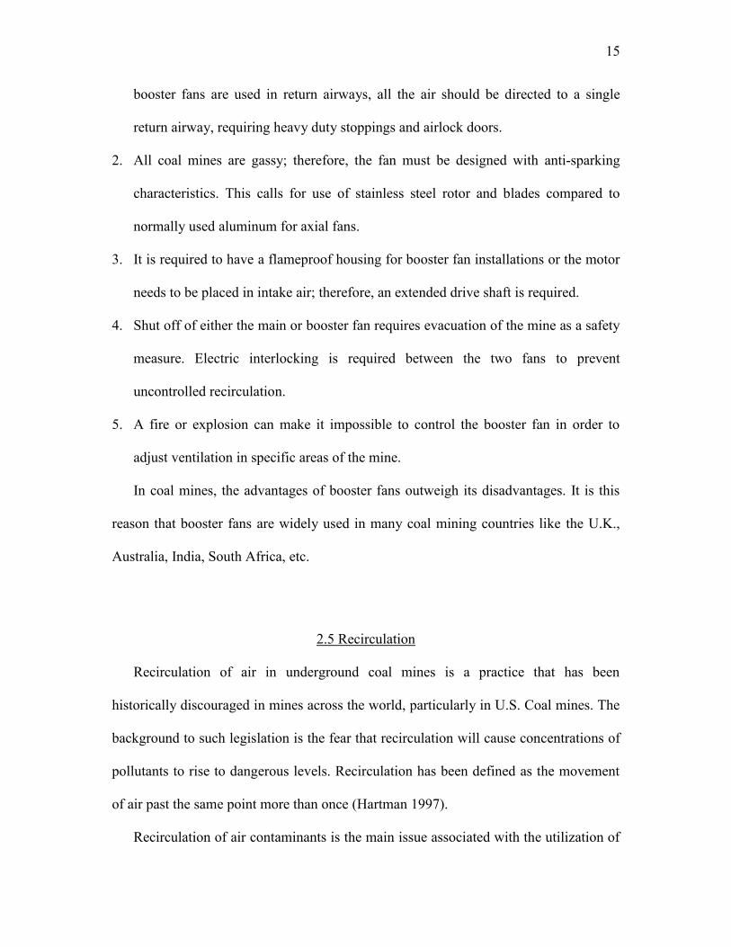
slashing existing drifts, and installing airlock doors. Figure 2.1 shows a schematic of a
booster fan installation in a drift.
Following simulation exercises and fan selection, the next task is site preparation
and fan installation. The installation begins with construction of concrete foundations,
followed with the installations of an overhead monorail, fan housing, bulkheads, airlock
doors and a prefabricated fixture between the diffuser and the bulkhead. Before
commissioning, the fan must be tested at no-load and full load conditions. During each
test, parameters such as vibration, bearing temperature, blade tip clearance, and power
consumption should be measured and compared against allowable limits defined by
regulations. The fan is commissioned only when the measured values are consistently
lower than the allowable limits.
2.3 Fan Monitoring and Control System
Monitoring and control systems have been used in the U.S. mining industry for the
last 4 decades. They have become more sophisticated over the years, and continuous
monitoring and control of underground machinery from the surface is a common
practice.
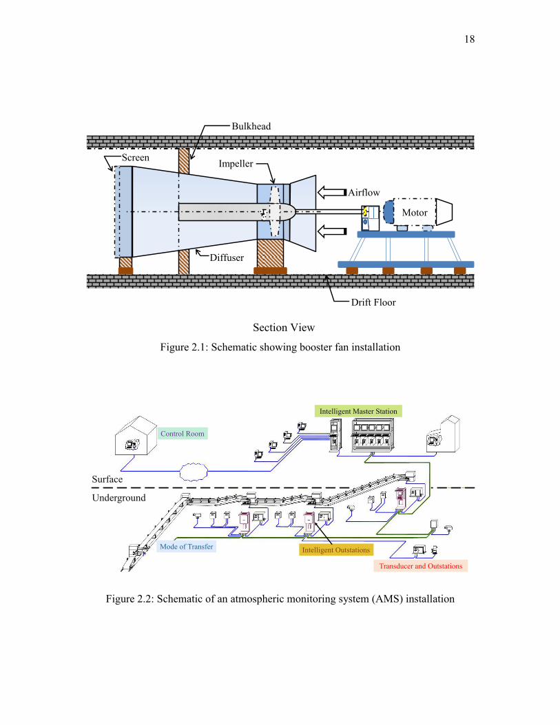
It is a system that performs three functions: sensing, data transmission, and data
processing (recording, analyzing, and displaying). In the case of monitoring and control
systems the “control” represents a fourth and separate function. A monitoring system

12
consists of a series of transducers and sensors installed at different places and mounted
on machines in the underground. They are further connected to the outstations and
intelligent stations through a programmable logical controller, fiber optic cable, or other
mode of transmission. The data are further transmitted to the surface for processing and
displaying on the computer screen in the control room. A schematic of atmospheric
monitoring is shown in Figure 2.2.
The control policies for any piece of machinery, including mine fans, are based on
existing regulations and industry best practices around the world. The control policy
basically defines the normal operating conditions and what actions need to be taken
when there is a deviation from normal conditions. In addition, the monitoring system
includes audio-visual alert and alarm devices that are activated automatically when
abnormal conditions are reported.
Mine operators continue to realize the benefits of improved fire detection
capabilities of the monitoring systems as the number of mines using the systems as well
as the percentage of mines continues to increase. One reason for the increase in
utilization is the cost effectiveness of atmospheric monitoring systems (AMS). Recent
cost analyses have shown that the initial cost of AMS is in some cases less than the
traditional fire detection systems (point-type heat sensors) used to comply with 30 CFR
§ 75.1103.
Continuous monitoring systems play a very important role in control of booster
fans. The monitors underground can be primarily divided into two categories;
environmental monitors and fan operation monitors. The major parameters monitored
by environmental monitors are airflow velocity (0 to 23 m s-1), air pressure (0 to 6 kPa),

13
carbon monoxide (0 to 50 ppm), methane (0–5%), and barometric pressure (0 to 103
kPa). The parameters monitored by condition monitors include vibration (0–5 mm s-1),
bearing temperature (0 to 250°C), motor voltage (0 to 600 VAC), motor current (0 to
400 Amps), and air flow direction indicator, on/off, and emergency off control devices
(Calizaya 1989).
Another important aspect of the booster fan monitoring is the fan interlock and
control system. It prevents any mishap in case of failure of the main or booster fans,
failure of airlock doors, fire prevention units, etc. This system mainly works on three
control routines, viz. hardware control, process evaluation, and redundant control. The
hardware control routine is predominantly used to check the status of main and booster
fans and operating conditions of the monitoring system. The process evaluation routine
is used to check the correctness of the collected data, in which the data evaluation is
performed on a transducer-by-transducer basis. The redundant control routine is
independent of the other two routines. It helps in re-examining the monitoring system
data in case of unexpected events such as electrical and/or mechanical failure to fans,
monitors, and control devices. The control system should be capable of
activating/deactivating all audio-visual alarms and shutting of the main or booster fans.
2.4 Advantages and Disadvantages
In coal mines, the installation of larger surface fans and sinking new shafts is given
preference over booster fan installations in the underground. This is mainly due to the
operational problems and economic considerations associated with booster fans. The
various advantages and disadvantages of these fans are discussed briefly in this section.

14
2.4.1 Advantages
There are several ways of gaining advantage from the use of a booster fan. Even if
booster fans are not suitable for every situation, they are capable of providing
improvements in various underground environments when properly sized and located
(Calizaya et al. 1989; McPherson 1993). Some of the possible advantages of booster
fans are
1. The airflow distribution in the mine is enhanced, especially in the difficult-to-
ventilate areas.
2. The pressure differentials from intake to return are reduced, hence reducing leakage
and need for airlocks.
3. The surface fan pressures are reduced, therefore allowing existing installations to
remain in place.
4. It can be used as a method to boost single panel(s) rather than the whole mine to
minimize use of regulators and hence mine resistance. A booster fan reduces the
effective resistance of a section.
5. The overall development costs are much less as compared to installation of large
surface fans or sinking a new shaft.
6. The operating electric power costs for booster fans is low as they augment main fan
power and less energy is lost because regulators are required.
2.4.2 Disadvantages
The major disadvantages of booster fans are
1. Most coal mines have multiple parallel intake and return airways; therefore, if
15
booster fans are used in return airways, all the air should be directed to a single
return airway, requiring heavy duty stoppings and airlock doors.
2. All coal mines are gassy; therefore, the fan must be designed with anti-sparking
characteristics. This calls for use of stainless steel rotor and blades compared to
normally used aluminum for axial fans.
3. It is required to have a flameproof housing for booster fan installations or the motor
needs to be placed in intake air; therefore, an extended drive shaft is required.
4. Shut off of either the main or booster fan requires evacuation of the mine as a safety
measure. Electric interlocking is required between the two fans to prevent
uncontrolled recirculation.
5. A fire or explosion can make it impossible to control the booster fan in order to
adjust ventilation in specific areas of the mine.
In coal mines, the advantages of booster fans outweigh its disadvantages. It is this
reason that booster fans are widely used in many coal mining countries like the U.K.,
Australia, India, South Africa, etc.
2.5 Recirculation
Recirculation of air in underground coal mines is a practice that has been
historically discouraged in mines across the world, particularly in U.S. Coal mines. The
background to such legislation is the fear that recirculation will cause concentrations of
pollutants to rise to dangerous levels. Recirculation has been defined as the movement
of air past the same point more than once (Hartman 1997).
Recirculation of air contaminants is the main issue associated with the utilization of

16
booster fans. It occurs when the pressure in the return airway is higher than the pressure
in the intake airway, causing the return air to leak from the return to the intake or back
to the working areas. In systems with multiple fans when the booster fans are not sited
or sized properly, the possibility of recirculation is quite high. There are two types of
recirculation: controlled flow recirculation and uncontrolled flow recirculation.
2.5.1 Controlled Recirculation
Controlled recirculation is a ventilation practice in which a specific fraction of the
air returning from a work area is passed back into the intake in a controlled fashion in
order to provide additional air quantity without adversely affecting other ventilation
variables. When properly designed, this practice can result in increased airflow quantity
at the workings, leading to overall lower general gas concentrations. The velocity of air
increases at the face, which results in better turbulent mixing of air and methane at the
point of release. Therefore, with controlled recirculation, the tendency of methane
layering, accumulation of explosive methane-air mixtures, and gas build-up is
decreased.
Depending upon the position of the booster fan in relation to the workings, there are
three types of controlled recirculation: (1) cross-cut recirculation, (2) in-line
recirculation, and (3) combined recirculation (as shown in Figure 2.3).
Controlled recirculation is used in deep mines to increase the face air velocity, to
control the concentration of air contaminants, and to reduce ventilation costs (Calizaya
2009). Although this technology is prohibited in U.S. underground coal mines, it is used
in metal and nonmetal mines.

17
2.5.2 Uncontrolled Recirculation
Uncontrolled recirculation occurs when air is leaked from the return airway to the
intake airway, but the leakage is not expected and the recirculating air is not managed,
so there is the potential for the buildup of air contaminants. It is often the result of poor
maintenance of stoppings and doors. Uncontrolled recirculation can take place if
stoppings are not sealed properly or if airlock doors are not able to withstand the
pressure. It is extremely dangerous for mine ventilation and is one of the biggest fears
associated with booster fan use in underground mines.
18
Figure 2.1: Schematic showing booster fan installation
Figure 2.2: Schematic of an atmospheric monitoring system (AMS) installation
Section View
Airflow
Screen
Diffuser
Bulkhead
Drift Floor
Impeller
Motor
Transducer and Outstations
Mode of Transfer
Control Room
Intelligent Outstations
Intelligent Master Station
Surface
Underground
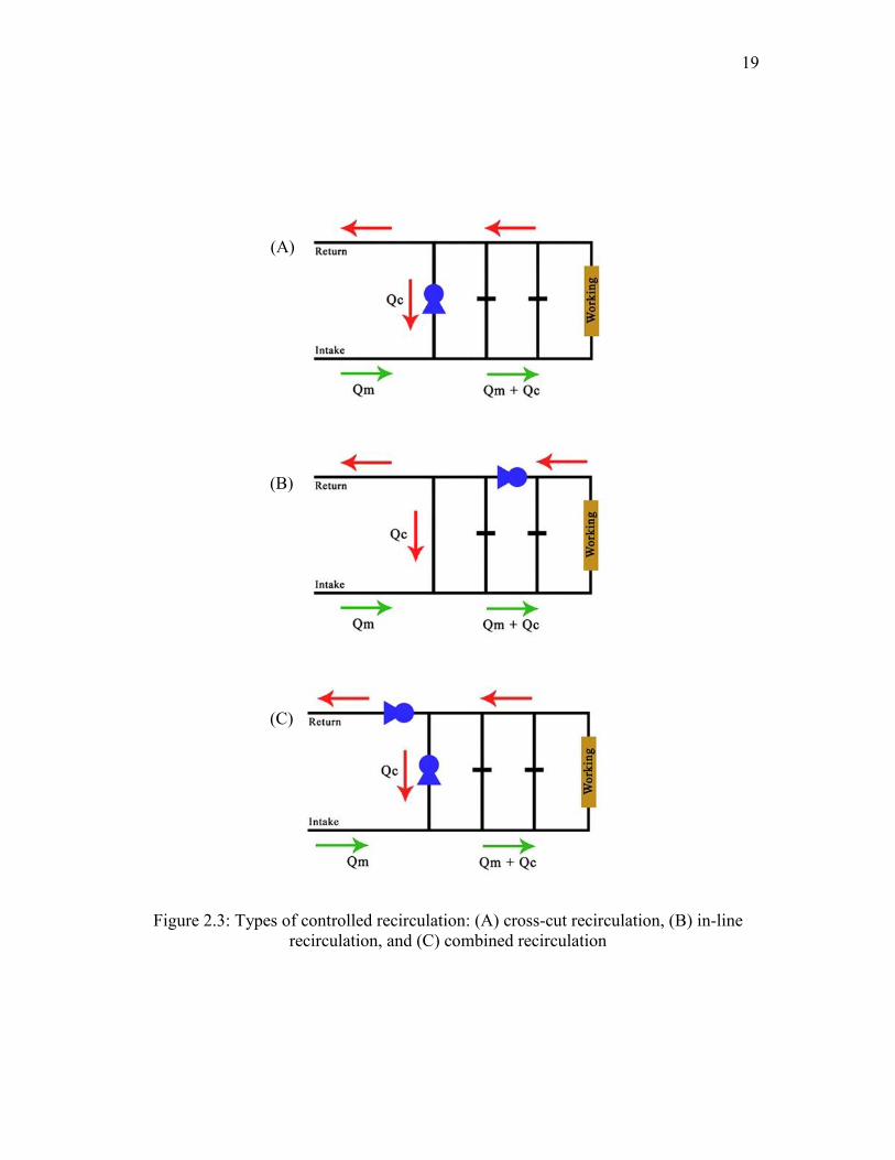
19
Figure 2.3: Types of controlled recirculation: (A) cross-cut recirculation, (B) in-line recirculation, and (C) combined recirculation
(A)
(B)
(C)
CHAPTER 3
MINE VENTILATION FORMULAE
In mine ventilation, the airflow is an example of a steady fluid flow process. It
means that none of the variables of flow changes with time, transitions, losses in
energy. The descriptions of different theories of fluid flow applicable to underground
mining are found in mine ventilation textbooks (Hall 1981; McPherson 1993; Hartman
et al. 1997). The basic principles and assumptions used in subsurface ventilation are
summarized in this chapter.
3.1. Fluid Flow Principles
The air is composed of different gases and water vapor and is compressible in
nature. However, it is considered as an ideal, incompressible gas if the mass density is
nearly constant. This condition exists in most mine ventilation situations. An exception
to this is when the mine is located at great depths where heating and cooling of air is
required and where the vertical movement of air is more than 500 m (1,640 ft). In these
situations, thermodynamics laws must also be considered. Since the heat energy is
neglected, the total energy at any section in a moving fluid (in this case air) consists of
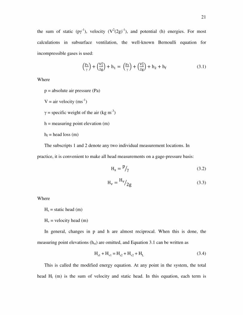
21
the sum of static (pγ-1
), velocity (V2(2g)
-1), and potential (h) energies. For most
calculations in subsurface ventilation, the well-known Bernoulli equation for
incompressible gases is used:
���γ
� + ������ + h� = ���
γ� + ����
�� + h� + h� (3.1)
Where
p = absolute air pressure (Pa)
V = air velocity (ms-1
)
γ = specific weight of the air (kg m-3
)
h = measuring point elevation (m)
hf = head loss (m)
The subscripts 1 and 2 denote any two individual measurement locations. In
practice, it is convenient to make all head measurements on a gage-pressure basis:
H� = pγ� (3.2)
H� = H� 2g� (3.3)
Where
Hs = static head (m)
Hv = velocity head (m)
In general, changes in p and h are almost reciprocal. When this is done, the
measuring point elevations (hst) are omitted, and Equation 3.1 can be written as
Hs1 + Hv1 = Hs2 + Hv2 + HL (3.4)
This is called the modified energy equation. At any point in the system, the total
head Ht (m) is the sum of velocity and static head. In this equation, each term is

22
expressed in terms of gage pressure:
Ht = Hs + Hv (3.5)
Pressure (Pa) measurements are obtained by multiplying the head values in
Equation 3.5 by the specific weight of air, giving
pt = ps + pv (3.6)
In mine ventilation, the modified energy equation is preferred over the steady state
energy equation.
3.1.1 State of Airflow
In our everyday world, we can observe many examples of the fact that there are two
basic kinds of fluid flow. A stream of oil poured out of a can on a slope flows smoothly
and in a controlled manner while water, poured out at the same rate, would break up
into cascading rivulets and droplets. This example suggests that the type of flow seems
to depend on the fluid type and its flow rate. In fluid mechanics, two distinct states of
fluid flow are defined: laminar and turbulent. The criterion used in establishing
boundaries for each state is the dimensionless Reynolds Number NR. Laminar flow
exists where NR < 2000 and turbulent flow where NR > 4000. The region between is
known as the transition range. For any fluid flow conditions, NR can be determined
from measurements and fluid properties:
N� = � = ��
� (3.7)
Where
NR = Reynolds Number (dimensionless)
ρ = density of the fluid (kg m-3
)
23
V = velocity of the fluid (m s-1
)
D = diameter of conduit (m)
μ = dynamic viscosity (Pa∙s)
v = kinematic viscosity (m2 s
-1)
In subsurface ventilation engineering, the characteristic length is normally taken to
be the hydraulic mean diameter of an airway, d, and the characteristic velocity is usually
the mean velocity of the airflow. In most mine airways, it is important that turbulent
flow always prevails to provide sufficient dispersion and removal of contaminants
(Kennedy 1996). Using typical dimensions of mine openings and air velocities in
Equation 3.7, it is evident that turbulent flow will nearly always prevail in any mine
airway. Exceptions to this include laminar flow in caved areas and "air-tight" stoppings
(Hartman et al. 1997). The state of airflow in a mine can also be perceived in terms of
resistance to airflow.
3.2 Airflow Resistance
The concept of airway resistance is of major importance in mine ventilation. The
cost of passing any given airflow through an airway varies directly with the resistance
of that airway. This is made up by friction and shock losses. The friction losses
typically constitute 70 to 90% of the total losses (Hartman et al. 1997). Friction losses
are caused by the drag forces between the walls and the air streams, which depend
primarily on the roughness of the individual wall surfaces. For example, moving air
through a smooth duct requires less power than moving air through the same size duct
with rough walls. Thus, rough walls have higher frictional resistance to flow.

24
In 1854, J. J. Atkinson published an equation that was originally derived from the
Chezy-Darcy fluid flow equation. Atkinson's Equation is applicable to incompressible
fluid flow that is turbulent in nature. As such, it is perhaps the most widely used
equation in mine ventilation:
∆p = ��.�.� !.��" � (3.8)
Where
∆p = differential pressure (Pa)
k = friction coefficient (kg m-3
, a function of density)
L = length (m)
Per = perimeter of the mine entry (m)
V = average velocity (m s-1
)
A = cross-sectional area (m2)
The parameters in Equation 3.8 are average values and/or differential measurements
between two locations. In mines, airflow quantities are calculated from measurements
of velocity and cross-sectional area of an airway:
Q = V·A (3.9)
Where
Q = airflow quantity (m3 s
-1)
Velocity, V, can be replaced with Q/A in Equation 3.8 and rewritten as:
∆p = ��.�.� !"# � ∗ Q� (3.10)
The friction factor k in mine ventilation corresponds to the coefficient of friction in
general fluid flow. It is assumed to be constant for a given airway, regardless of the
Reynolds number. It only changes with the density of air.

25
Whenever the airflow changes direction, additional vortices are formed. The
propagation of these large-scale eddies consumes mechanical energy (shock losses) and
hence, the resistance of the airway may increase significantly. This occurs at bends,
junctions, changes in cross-section, obstructions, regulators, and at points of entry or
exit from the system. The effects of shock losses remain the most uncertain of all the
factors that affect airway resistance. This is because fairly minor modifications in
geometry can cause significant changes in the generation of vortices and, hence, the
airway resistance. In general, the shock loss is calculated by multiplying the shock loss
factor and velocity head. The shock loss factor depends on a number of parameters such
as geometry of the airway, angle of bend, change of area, etc.
P' = X × P� (3.11)
Where
Px = Shock loss
X = Shock loss factor
Pv = Velocity head
Shock loss plays an important role in designing the fan houses, etc. They can range
as high as 30% loss of pressure.
3.3 Leakage Flow
Leakage of air is one of the major problem in mine ventilation systems. In coal and
metal mines, leakage is the most common cause of inefficient distribution of air. While
leakage in coal mine ventilation systems averages 50% of total volume of air circulated,
in metal mines, it averages about only 25%. Leakage flow is defined as any quantity of

26
air that is not usefully employed somewhere in the mine. This quantity can be
determined indirectly:
Q� = Q* − ∑Q- (3.12)
Where
QL = leakage quantity (m3 s
-1)
QT = total air quantity at the fan (m3 s
-1)
QE = air quantity reaching a working area (m3 s
-1)
A working area in a coal mine is any location in the mine that requires a minimum
fixed quantity of air. It includes longwall (LW) and continuous miner (CM) sections,
underground shops, charging stations, bleeder monitoring points, gob seals, and
pumping stations.
The total percent leakage in the system is the ratio of the quantity of air that is short-
circuited before reaching the working areas to the total quantity circulated by the fan. It
is calculated as follows:
L* = /1002 × /Q* − ∑Q-2/Q* (3.13)
Where
LT = total leakage (%)
Another important aspect related to leakage flow is volumetric efficiency. The
volumetric efficiency of the mine is defined as
Volumetric Efficiency = B� �CD "E!�DFG*FHID "E!�DFG HJ!FCJ KIEL �IL/�2 × 100% (3.14)
The useful airflow can be defined as the sum of the airflows reaching working faces
and important parts of the mine such as electrical gear, pumps, charging stations, etc.
(McPherson 1993). The volumetric efficiency of mines may vary from 10–75%.
27
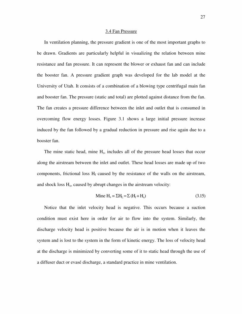
3.4 Fan Pressure
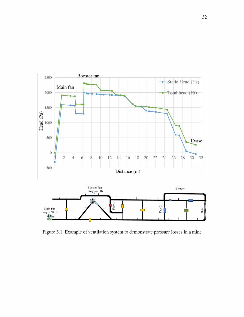
In ventilation planning, the pressure gradient is one of the most important graphs to
be drawn. Gradients are particularly helpful in visualizing the relation between mine
resistance and fan pressure. It can represent the blower or exhaust fan and can include
the booster fan. A pressure gradient graph was developed for the lab model at the
University of Utah. It consists of a combination of a blowing type centrifugal main fan
and booster fan. The pressure (static and total) are plotted against distance from the fan.
The fan creates a pressure difference between the inlet and outlet that is consumed in
overcoming flow energy losses. Figure 3.1 shows a large initial pressure increase
induced by the fan followed by a gradual reduction in pressure and rise again due to a
booster fan.
The mine static head, mine Hs, includes all of the pressure head losses that occur
along the airstream between the inlet and outlet. These head losses are made up of two
components, frictional loss Hf caused by the resistance of the walls on the airstream,
and shock loss Hx, caused by abrupt changes in the airstream velocity:
Mine Hs = ΣHL = Σ (Hf + Hx) (3.15)
Notice that the inlet velocity head is negative. This occurs because a suction
condition must exist here in order for air to flow into the system. Similarly, the
discharge velocity head is positive because the air is in motion when it leaves the
system and is lost to the system in the form of kinetic energy. The loss of velocity head
at the discharge is minimized by converting some of it to static head through the use of
a diffuser duct or evasé discharge, a standard practice in mine ventilation.

28
3.5 Recirculation
Recirculation of contaminated air in underground coal mines is an unsafe practice
that has been discouraged historically across the world, particularly in U.S. coal mines.
The main reason is that recirculation may cause concentrations of pollutants to rise to
dangerous levels. Recirculation has been defined as the movement of air past the same
point more than once.
Recirculation of air contaminants is the main hazard associated with the utilization
of booster fans. It occurs when the pressure in the return airway is higher than the
pressure in the intake airway, causing the return air to leak from the return to the intake.
In systems with multiple fans when the booster fans are not sited or sized properly, the
risk of recirculation might be quite high.
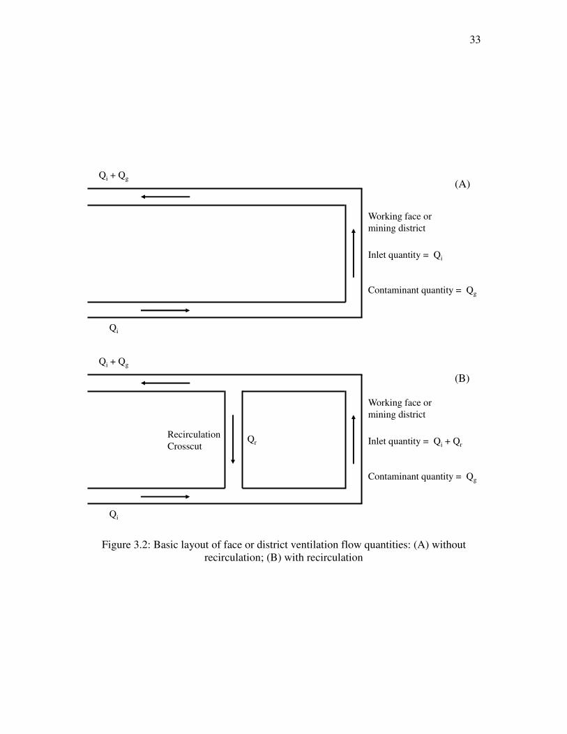
The recirculation of air and recirculation fraction (CR) can be better understood with
the two mine ventilation diagrams shown in Figure 3.2. In Figure 3.2(A), a section or
mining district is ventilated by a quantity of air Qi that contains a decimal proportion of
the contaminant Ci. At the working face, a quantity of contaminant Qg is introduced into
the air-stream and increases the level of contamination. As a result of this set of
conditions, the following ventilation parameters are found in the mine:
C� = OPQPROSOPROS
(3.16)
Where
CR = recirculation fraction
In order to increase the air at the working face without increasing the amount of
intake air, a recirculation circuit is set up by developing a recirculation crosscut as
shown in Figure 3.2(B). A fixed quantity of air Qr is deliberately recirculated through
29
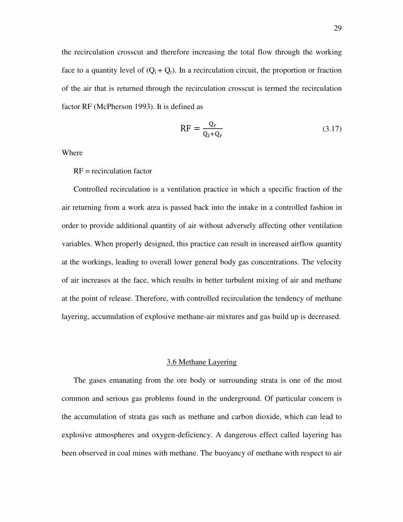
the recirculation crosscut and therefore increasing the total flow through the working
face to a quantity level of (Qi + Qr). In a recirculation circuit, the proportion or fraction
of the air that is returned through the recirculation crosscut is termed the recirculation
factor RF (McPherson 1993). It is defined as
RF = OVOPROV
(3.17)
Where
RF = recirculation factor
Controlled recirculation is a ventilation practice in which a specific fraction of the
air returning from a work area is passed back into the intake in a controlled fashion in
order to provide additional quantity of air without adversely affecting other ventilation
variables. When properly designed, this practice can result in increased airflow quantity
at the workings, leading to overall lower general body gas concentrations. The velocity
of air increases at the face, which results in better turbulent mixing of air and methane
at the point of release. Therefore, with controlled recirculation the tendency of methane
layering, accumulation of explosive methane-air mixtures and gas build up is decreased.
3.6 Methane Layering
The gases emanating from the ore body or surrounding strata is one of the most
common and serious gas problems found in the underground. Of particular concern is
the accumulation of strata gas such as methane and carbon dioxide, which can lead to
explosive atmospheres and oxygen-deficiency. A dangerous effect called layering has
been observed in coal mines with methane. The buoyancy of methane with respect to air
30
(specific gravity 0.554) produces a tendency for concentrated methane to collect in roof
cavities and to layer along the roofs of airways or working faces.
There are two main hazards associated with methane layers. First, they extend
greatly in poorly ventilated areas to form layers of gas that can ignite. Secondly, when
such an ignition has taken place, a methane layer acts very effectively as a fuse along
which the flame can propagate rapidly—perhaps leading to much larger accumulations
in roof cavities or gob areas that can cause explosions (McPherson 1993).
To foreworn of the likely occurrence of methane layering, Leach and Thompson
developed an empirical indicator, layering number Nl, which can be calculated from this
relationship:
ND = �W�.X Y Z
OS[
�/\ (3.18)
Where
Vu = air velocity in the upper half of the airway (m s-1
)
Qg = methane inflow (m3 s
-1)
b = airway width
The empirical results have defined that layering can be controlled if the air velocity
is sufficient to maintain Nl at values ≥ 5 in a horizontal airway, 5 in an airway with
uphill flow (8 if steep), and 3 in an airway with downhill flow (5 if steep). Irrespective
of airway slope, a safe approximate value of Nl to use on normal grades is thus 5. In a
typical coal mine, openings with moderate gas inflows and high air velocities (≥ 1 m/s)
may be required to counteract the layering effect.
In the case of products of combustion, dispersion and diffusion also play a very
important role. The rate of diffusion of a gas into air is inversely proportional to the

31
square root of specific gravity of the gas. In other words, a gas lighter than air will
diffuse faster than one heavier than air. Diffusion is also aided by turbulence and
temperature.
When a plume of combustion products rises towards the mine roof due to the
thermally induced density differences between the hot products-of-combustion (POC)
and the ambient air, the POC will also be convected with the bulk air flow downwind
from the fire source. The POC will be dispersed by the dilutive mixing with the fresh air
over the entry cross-section downwind from the source fire. This dispersion process is
enhanced by the thermal equilibration of the POC with the ambient air. It is therefore
important to know the expected distribution of CO near the mine roof in smoldering and
flaming coal fire to control the fire hazard (Edwards 2006).
32
Figure 3.1: Example of ventilation system to demonstrate pressure losses in a mine
-500
0
500
1000
1500
2000
2500
0 2 4 6 8 10 12 14 16 18 20 22 24 26 28 30 32
Hea
d (
Pa)
Distance (m)
Static Head (Hs)
Total head (Ht)
Evase
Main Fan
Freq. = 60 Hz Go
b
Booster Fan
Freq. =40 Hz
Fac
e 1
Fac
e 2
Bleeder
Main fan
Booster fan
33
Figure 3.2: Basic layout of face or district ventilation flow quantities: (A) without
recirculation; (B) with recirculation
Qi + Qg
Qi
Working face or
mining district
Inlet quantity = Qi
Contaminant quantity = Qg
Qi + Qg
Qi
Working face or
mining district
Inlet quantity = Qi + Qr
Contaminant quantity = Qg
QrRecirculation
Crosscut
(A)
(B)

CHAPTER 4
ATMOSPHERIC MONITORING SYSTEMS
Atmospheric monitoring systems (AMS) are used as a means to measure and
evaluate the air quality and quantity in the mine and to develop strategies to control
potential fire hazards. The application of these systems in coal mines has increased
rapidly in the last 20 years (Francart 2005). One reason for this increase is the cost
effectiveness of the system. Recent cost analyses have shown that the initial cost of an
AMS is often less than the cost of traditional fire detection systems. While maintenance
costs increase the overall cost of the AMS, effective early fire detection can save the
mine operator many times its initial investment by preventing losses in production and
recovery of fire areas.
The major manufacturers of the AMS are Pyott-Boone, AMR, CONSPEC, MSA,
and Rel-Tek. These companies are the market leaders in the United States. Around 90%
of the systems installed in coal mines are used for belt conveyors, and more than half of
them are used to monitor ventilation parameters including main fan duties. AMS can
easily be interfaced with booster fan monitoring systems. It provides the AMS operator
booster fan monitoring data along with the AMS data.

35
4.1 Terminology
Monitoring: The word monitoring originates in Latin where it means one who warns
or admonishes. In reference to mining, monitoring means measuring certain
parameters of mining, transmitting data for processing and then using the data as
input for decision-making. Monitoring is used for protection from a safety hazard
such as fires or explosions or for protection from a health hazard such as a toxic gas.
Transducer: It is a device that is a component of a monitoring and control system. It
is actuated by a one-transmission subsystem and supplies related waves to a
receiver. In another sense a transducer is a device that measures certain parameters
of a system such as pressure, current, and voltage and converts them into related or
proportional units. It converts a signal in one form of energy to another form of
energy. Energy types include (but are not limited to) electrical, mechanical,
electromagnetic, chemical, acoustic, and thermal energy. In this sense a transducer
is used as a synonym for a sensor.
Sensor: A sensor is a converter that measures a physical quantity and converts it into
a signal that can be read by an observer or by an electronic instrument that is a part
of a monitoring and control system."
Outstation: Outstations or field data stations represent a point of aggregation in a
hierarchical structure of data flow. They serve as an economical compromise by
allowing access to the communication trunk by a number of sensors. The major
function of an outstation is to provide a communication interface between a sensor
and the trunk connected to the central station computer.
Monitoring System: It is a system that performs three functions: sensing, data

36
transmission, and data processing (recording, analyzing, and displaying). In the case
of monitoring and control systems, the ―control‖ represents a fourth and separate
function. This system is called a ―monitoring and control system.‖
Data Acquisition System: Data acquisition is the process of sampling signals that
measure real world physical conditions and converting the resulting samples into
digital numeric values that can be manipulated by a computer. Data acquisition
systems typically convert analog waveforms into digital values for processing.
Threshold Limit Values (TLV): It refers to those concentrations within which
personnel may be exposed without known adverse effects to their health or safety.
Time-Weighted Average (TWA): It is the average concentration to which nearly all
workers may be exposed over an 8-hour shift and a 40-hour work week without
known adverse effects.
Short-Term Exposure Limit (STEL): It is a time-weighted average exposure for
duration of 15 minutes that cannot be repeated more than 4 times per day with at
least 60 minutes between exposure periods.
Ceiling Limit (TLC-C): It is the concentration that should not be exceeded at any
time. It is mostly relevant for the most toxic substances or those that produce an
immediate irritant effect.
A schematic of an AMS installation in a mine is shown in Figure 4.1
4.2 Transmission of Data
Conventional AMS installations for monitoring CO, Smoke, CH4, O2, and fan
parameters throughout underground mines are usually relegated to a modest 3–5 mile

37
extent and with data communication speeds confined to a ponderous 1–5K baud range
(Ketler 2008). New MSHA and state regulations require fast reporting of unsafe
conditions, and the old 20–30 minute updates are no longer acceptable. To
communicate farther and faster has always been a problem because data reliability
degenerates with excessive distances and high speeds. Presently, there are four major
types of data transmission modes based on the principles of wireless communication,
programmable logic controllers, fiber optics, and telemetering system.
In wireless monitoring, a network of wireless sensors gathers environmental data
and real-time status information from different mining operations. The mines of the
future will see a number of instruments with the highest level of reliability at the lowest
possible cost. One of the key areas of the next generation instrumentation is wireless
monitoring systems in underground coal mines. Emerging wireless networking
technologies are opening up opportunities for new systems, achieving significant cost
savings in equipment design and maintenance as well as significant reductions in time-
lost incidents due to injuries in mining operations (Smutny 2003).
A Programmable Logic Controller (PLC) is a digital computer-based system used in
underground mines for automation and control. The initial systems utilized mini
computers on the surface as the intelligence of the system. The remote outstations were
not intelligent, being wholly dependent on the remote mini computers to collect
information from and then to process the data to make logical decisions. Therefore, all
logic decisions were made by the microcomputer on the surface based on scanned input
data (Smallwood et al. 1993). Currently, monitors are placed along the belt lines and are
linked to the host computer in the control room through a PLC network. The monitors
38
can detect a rise in carbon monoxide or concentrations of other combustible gases,
which helps by giving out an early warning of potential hazards. The collected
information is immediately transmitted to the surface, so the operator can clearly locate
the problem area, determine the existing conditions, shut down processes in that section,
and restart when conditions permit (Conspec 2014).
A fiber-optic monitoring system uses a method of transmitting information from one
place to another by sending pulses of light through an optical fiber. The fiber-optic
systems are much more efficient than the PLC based systems as they can be laid out to
much further distances in large mines and are faster in communication speed. The
optical fiber technology offers an intrinsically safe, rapid, reliable, and accurate method
of sensing and monitoring. The drawback with fiber optics system is that they have high
initial cost as well as high maintenance costs and downtime costs to repair or replace
broken optical fibers (CRC mining 2013).
Telemetry is the highly automated communication system by which measurements
are made and other data collected at remote or inaccessible points and transmitted to
receiving equipment for monitoring and control. The telemetry monitoring systems
have intelligent outstations along with an intelligent master station on the surface.
Telemetry systems provide an inexpensive alternative to expensive fiber optic systems
by using a communication data highway, which uses inexpensive twisted-pair telemetry
cables, which can communicate well into the 20-mile extent of the largest mines (Ketler
2008).
39
4.3 Implementation of AMS in the U.S.
AMS have evolved rapidly since the 1970s, an area that the Bureau of Mines and
the Mine Safety and Health Administration (MSHA) foresaw as having huge potential
for safety improvements. Mine operators continue to realize the benefits of improved
fire detection capabilities as the number of mines using the systems continues to
increase.
Fire detection data and new technology implemented in underground coal mines
have been reviewed as well as the regulatory compliance, diesel exhaust emissions, and
hydrogen interference in carbon monoxide detection. Compliance with federal
regulations or petitions for modification (PFM) of federal regulations is the major cause
for installation of AMS in many mines (Francart 2005).
MSHA has conducted multiple surveys over the last 3 decades to monitor the
implementation of AMS in the United States. This survey was first completed in 1984
and has been periodically updated with the latest survey data released in 2003. In 1984,
only 38 mines used AMS in monitoring for mine fires. In 2003, the survey indicates that
the number of mines using AMS had increased to 146. The number is believed to be
much higher now. The increase in the number of installations is more dramatic when
the number of mine closures is considered. In 1992, 115 mines used AMS. Of this
number, 79 have been removed from the survey, mostly due to mine closure. This
yields an increase of 110 new AMS installations in underground coal mines in the past
10 years.
The increased implementation of AMS technology can be attributed to two main
factors. First, carbon monoxide (CO) detection technology is far superior to the heat

40
sensor technology used in mines for decades. The detection of reportable fires by
atmospheric monitoring systems using carbon monoxide sensors in belt entries has been
flawless since 1984. Second, the initial cost of an AMS system is competitive with
traditional heat sensor systems. For mines monitoring beltlines only, the initial capital
cost for an AMS can be less than heat sensors when more than 2,750 m (9,000 ft) of belt
are monitored. While maintenance and operating costs will cause the overall costs to be
greater for the AMS, there is no doubt that many mine operators have decided the cost
benefit of early detection of belt fires is justification for the AMS installation.
Many AMS installations monitor a variety of mine functions in addition to
providing fire detection in the belt entry. It is reported that almost 90% of mines
monitor the belt operations. Fan stoppage is monitored in 42% of the mines as the
second most monitored function. Twenty-two percent of mines monitor for methane
using AMS. Table 4.1 shows the functions monitored as a percentage of AMS
installations (Francart 2005).
4.4 Environmental Monitoring
Industrial and commercial application of computerized mine monitoring systems
started in the early 1970s. Since then, the systems have been developed and improved
significantly. The modern systems can monitor the mine environment, equipment
performance, and work force. Monitoring systems are used in almost all the mines in
the United States, and the other operators are considering future installation of these
systems. Mining operations, especially in large coal mines, rely upon monitoring
systems to provide safe and healthy work conditions to workers. Presently, various
41
monitoring systems are in industrial use in coal mines; several new systems are being
developed, and others are waiting to be approved for specific mining and geological
conditions. The various methods for monitoring gases underground are discussed in this
section and in further detail in Appendix A.
4.4.1 Gas Sensing Methods
The primary purpose of environmental monitoring is to ensure that the atmosphere
in the mine is free from toxic or flammable airborne pollutants. The parameters that are
essential for designing an environmental monitoring system for a mine are (1) air
contaminant, (2) type of sensor, and (3) location, spacing, and frequency of these
sensors.
4.4.1.1 Performance Indicators and Gas Sensor’s Stability
To evaluate the performance of gas sensing methods, several factors should be
considered:
1. Sensitivity: the minimum value of target gas concentration
2. Selectivity: the ability of gas sensors to identify a specific gas among a gas mixture.
3. Response time: the period from the time when gas concentration reaches a specific
value to that when sensor generates a warning signal.
4. Reversibility: whether the sensor could return to its original state after detection.
5. The principle and performance of different gas sensing methods based on the above
performance indicators are described in Appendix A.

42
4.4.2 Classification and Monitoring of Mine Gases
When air enters a mine atmosphere it has a volume composition of approximately
78% nitrogen, 21% oxygen, and 1% other gases on a moisture free basis. However, this
composition changes as air moves through different airways of the mine. This happens
because of two reasons. First, mining allows strata gases such as carbon dioxide and
methane to enter the ventilating air. These gases are produced over geological time and
are entrapped in the strata. Secondly, a number of chemical reactions take place in the
ventilating air, which changes its composition. Oxidation reduces the percentage of
oxygen and often causes evolution of carbon dioxide or sulfur dioxide. Incomplete
oxidation leads to an increase in carbon monoxide in air. A primary requirement of a
mine ventilation system is to dilute and remove airborne pollutants, including dust and
toxic gases. Therefore, an environmental monitoring system is of utmost importance for
an efficient and safe mine ventilation system (McPherson 1993).
The gases that are most commonly encountered in underground are discussed in
further detail in this section and are summarized in Table 4.2.
4.4.2.1 Carbon Monoxide
Carbon monoxide (CO) is a colorless, odorless, and tasteless gas that is slightly less
dense than air. The high toxicity of carbon monoxide coupled with its lack of smell,
taste, or color make this one of the most dangerous and insidious of mine gases. Most
fatalities that have occurred during fires and explosions in mines have been a result of
carbon monoxide poisoning. The hemoglobin present in the blood has a very high
affinity for carbon monoxide.
43
The high toxicity of CO makes it very important to have a good monitoring system
for continuous monitoring. Since CO is one of the first products of combustion, it also
acts as a parameter for early detection of fire underground. CO detectors are designed to
measure CO levels over time and sound an alarm before dangerous levels of CO
accumulate in an environment, giving people adequate warning to safely ventilate the
area or evacuate. The common sensors that are used for detection of CO are based on
catalytic oxidation, electrochemical reaction, semiconductors, and infrared absorption
principles. The time weighted average (TWA) value is .005% (50 ppm), and the short
term exposure limit (STEL) value is .04% (400 ppm) for carbon monoxide.
4.4.2.2 Methane
Methane is one of the most common strata gases. It is produced by bacterial and
chemical action on organic material during the formation of coal. Methane is not
particularly toxic but it is flammable and can form explosive mixtures with air. This has
resulted in the fatalities of many thousands of miners. Methane is retained within
fractures, voids, and pores in the rock either as a compressed gas or adsorbed on
mineral surfaces. When the strata is pierced by boreholes or mined openings, then the
gas pressure gradient that is created induces migration of the methane towards those
openings through natural or mining-induced fracture patterns. Methane has a density
that is a little over half that of air. This gives rise to a dangerous behavior pattern in
which methane forms pools or layers along the roofs of underground openings. Any
ignition of the gas can then propagate along those layers to emission sources. The
buoyancy of methane can also create problems in inclined workings. In an abundant

44
supply of air, methane burns to produce water vapor and carbon dioxide.
The explosive range for methane is normally quoted as 5 to 15% by volume in air. It
is considered to be most explosive at around 9.8% by volume in air. According to
legislation, 30 CFR § 75.342 directs that MSHA approved methane monitors shall be
installed on all face cutting machines, continuous miners, longwall face equipment,
loading machines, and other mechanized equipment used to extract or load coal within
the working place. The sensing device for methane monitors on longwall shearing
machines shall be installed at the return air end of the longwall face. It is recommended
that when the methane concentration at any methane monitor reaches 1% the monitor
shall give a warning signal and automatically de-energize electric equipment or shut
down diesel-powered equipment when the methane concentration at any methane
monitor reaches 2%. Mine personnel should also be removed from the mine when the
concentration of methane reaches 2%.
The common sensors that are used in monitoring of methane are based on the
principles of catalytic oxidation, thermal conductivity, and flame safety lamps.
4.4.2.3 Smoke
Smoke is an aerosol that is formed by incomplete combustion and ordinarily
consists of particles 0.01–1.0 micrometers in size. Smoke particles are usually visible
and distinguished from fumes by the fact that they do not result from condensation
processes. Smoke is one of the products of combustion and acts as a good indicator of a
fire underground. Smoke sensors can be classified into two types based upon their
operational principle: ionization and optical.

45
Ionization smoke sensors use a radioisotope such as americium-241 to produce
ionization in air. The oppositely charged ions form a current between two charged
electrodes. Diffusion of smoke particulates into the path of the ion current reduces the
ion current. This process increases the ion’s probability of recombination. The ion
current reduction is amplified as a measurable signal.
Optical smoke sensors operate on the principle of scattering or absorption of light
over an optical path through which the smoke particles migrate. For optical scattering,
the sensor is located to the side of the optical path to measure the amount of light
scattered by a smoke particle. In the case of optical absorption, the reduction of
transmitted light due to absorption and scattering is measured.
In summary, ionization sensors are more sensitive to the smaller smoke particles
associated with flaming combustion, whereas optical sensors are more sensitive to
larger smoke particles associated with smoldering combustion (Edwards 2006).
4.4.2.4 Oxygen
Oxygen is an important part of the mine atmosphere as it is used in respiration. In
mines, the oxygen concentration is maintained at levels between 18.5 and 23% (as per
30 CFR § 7.506). The concentration should be on the higher side, close to 21.5% in the
fresh air. There are several techniques that are available for monitoring the oxygen
concentration. One common method for mine sensors is a simple battery type
electrochemical cell. The air is allowed to diffuse through a membrane to a cathode
where oxygen is reduced to hydroxyl ions. The anode is oxidized producing a current
proportional to the oxygen concentration. A membrane diffuser barrier is used to set the

46
rate of oxygen transport to the cathode to be proportional to the oxygen concentration.
The cell is operated in the current limiting region where all the oxygen reaching the
electrode is consumed.
As air flows through an underground facility, it is probable that its oxygen content
will decrease. This occurs not only because of respiration but, more importantly, from
the oxidation of minerals (particularly coal and sulfide ores) and imported materials.
The burning of fuels within internal combustion engines and open fires also consume
oxygen. The oxygen concentration can easily drop below 19% in poorly ventilated areas
such as old workings, bleeders, etc. Oxygen deficiency implies an increased
concentration of one or more other gases.
4.4.2.5 Carbon Dioxide
Carbon dioxide appears in a mine from a variety of sources such as strata emissions,
oxidation of carbonaceous materials, internal combustion engines, blasting, fires,
explosions, and respiration. The specific gravity of CO2 to dry air is 1.5 and will,
therefore, tend to collect on the floors of mine workings. It is common to find
emanations of CO2 from the bottoms of seals behind which are abandoned workings,
particularly during a period of falling barometric pressure. The concentration of CO2 in
air is normally 0.037%, but when it increases to 2%, the lung ventilation increases by
50% leading to intolerable panting, severe headache, and collapse as exposure increases
over time.

47
4.4.3 Thermal Sensors
Thermal sensors respond to environmental changes produced by the presence of a
fire. Thermal sensors are not reliable for detecting fires in underground mines; they
have been phased out in the last few years. Thermal sensors work on a simple principle
of detecting an increase in air temperature and actuate an alarm that signals the presence
of a fire condition. Commonly used thermal sensors are primarily based on
thermocouples. A thermocouple is a bimetallic junction that generates an electromotive
force when heated. They are fairly rugged and suffer no adverse effects from humidity
or convection cooling owing to the ventilation flow. Another widely used thermal
sensor is a thermoresistive type. These sensors change their resistance as the
temperature increases. However, these devices should be maintained at a fairly constant
humidity and should not be subjected to excessive changes in the ventilation flow.
These factors can adversely affect the sensitivity and, hence, the reliability of the
sensor. Other types of thermal sensors include line-type heat sensors, fixed-temperature
sensors, rate-of-temperature rise sensors, and pressurized heat-sensitive plastic tubes.
In general, thermal sensors work fine, but the time response can be quite long
(several minutes). If a fire occurred immediately adjacent to a thermal sensor, it would
respond rapidly, but if a fire occurred far away from a thermal sensor, the ventilation
flow would be required to carry the warm air to the sensor. Along the way, the air
would cool, and the time response could be too long to initiate any corrective action
(Litton 1979).
48
4.5 Condition Monitoring
A well-maintained and low cost mining operation requires the use of condition
monitoring techniques. Condition monitoring is the process of measuring environmental
and fan operating factors to evaluate and predict the health and safety conditions of the
mine fans. An adequate and reliable condition monitoring system is quintessential for a
mine using a booster fan ventilation system. This includes the measurement and
evaluation of the following variables: vibration, barometric pressure, noise, power,
bearing temperature, differential pressure, and quantity of airflow.
4.5.1 Vibration
In its simplest form, vibration can be considered to be the oscillation or repetitive
motion of an object around an equilibrium position. The equilibrium position is the
position the object will attain when the force acting on it is zero. Vibration in a system
is a factor that can cause machinery distress. Identifying the vibration level that is due to
the changed operational parameters can prevent potential damage. Vibration analysis is
a powerful tool to assess the performance of mine fans. Variations in normal operating
conditions in mine fans produce significant changes in vibration level. It also causes
wear or deterioration of the fan’s condition. The cause of fan vibrations can be either
internal or external. The internal sources of vibration are defects in manufacturing or
machine problems such as being out of balance, misalignment, or looseness. External
factors responsible for producing vibration in the system include the operation of the
fan in the stall region, changes in the equivalent orifice of the ventilation system, and
changes in the rpm of the fan (Mukhopadhyay 1998). Fans often exhibit excessive

49
vibration due to aerodynamic forces and flow turbulence. When excessive vibration at
the aerodynamic frequency (i.e., at the blade frequency) is encountered, a common
cause is the resonance of some part of the fan. It may also be due to obstructions that
disturb the smooth flow of air through the fan.
There are two types of vibrations: forced and free. An elastic body will vibrate
freely at one or more of its natural frequencies if an external force momentarily disturbs
its equilibrium. The motion will gradually die down because of damping. If an external
force is applied repeatedly, an elastic body will vibrate at the frequency of the external
excitation, whether this coincides with a natural frequency or not. The modes of
vibration are classified according to their numerical order and the direction of vibration
relative to the principal axis of the part or member. The direction of oscillation may be
longitudinal, lateral, or angular. Longitudinal vibrations are seldom serious in fan parts.
Lateral vibrations cause bending. Angular vibrations lead to torsion. The first bending
mode may have a higher or lower frequency than the first torsional mode, depending on
the geometry and material of the part (Jorgenson 1999).
After reviewing the current technology and industry practice of vibration
monitoring, it is recommended to have at least six vibration monitors (velocity type):
two for the fan fixed bearing, one for fan floating bearing, two for the motor nondrive
end, and one for the motor drive end. Although these monitors are extremely useful and
necessary for minimizing fan system damage, they are somewhat limited in predicting
potential failure. To that end, further vibration monitoring (acceleration type) is
recommended. This technique allows frequency analysis of the vibration to be
undertaken and is therefore more useful in predicting potential failure.
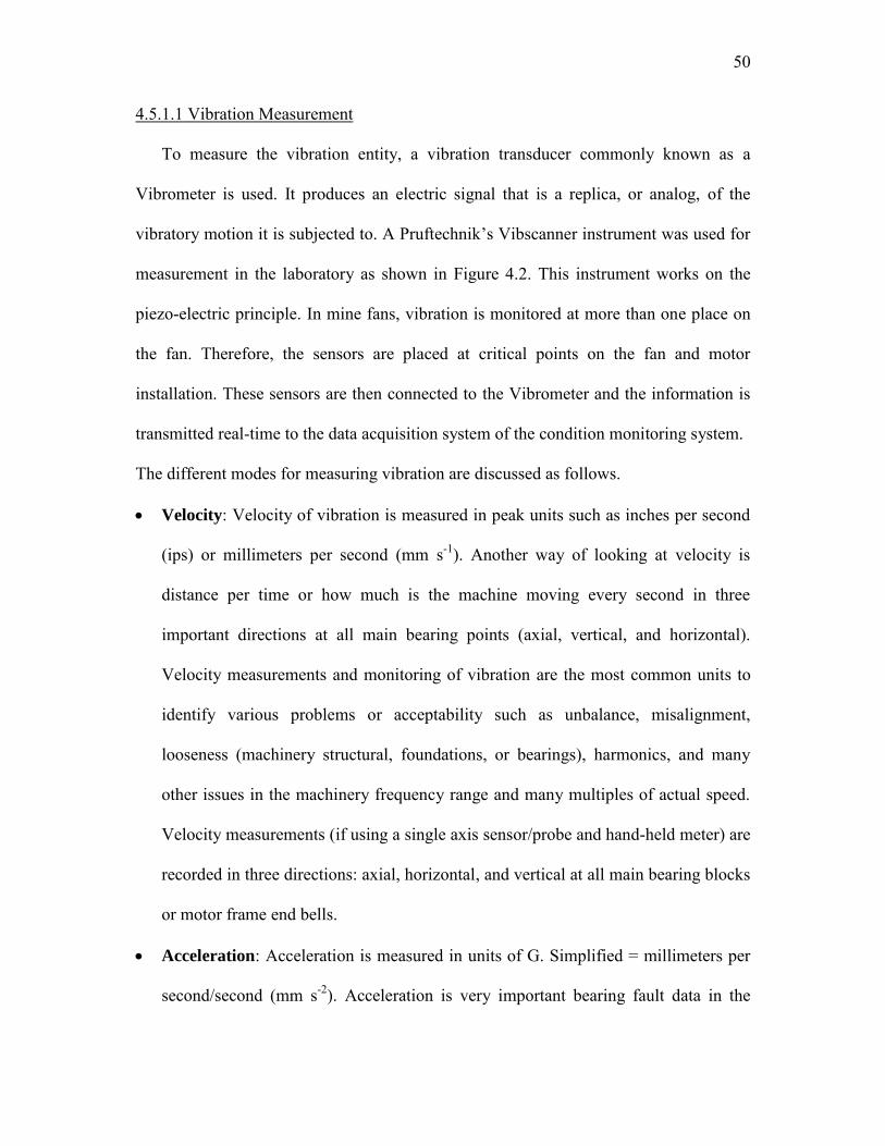
50
4.5.1.1 Vibration Measurement
To measure the vibration entity, a vibration transducer commonly known as a
Vibrometer is used. It produces an electric signal that is a replica, or analog, of the
vibratory motion it is subjected to. A Pruftechnik’s Vibscanner instrument was used for
measurement in the laboratory as shown in Figure 4.2. This instrument works on the
piezo-electric principle. In mine fans, vibration is monitored at more than one place on
the fan. Therefore, the sensors are placed at critical points on the fan and motor
installation. These sensors are then connected to the Vibrometer and the information is
transmitted real-time to the data acquisition system of the condition monitoring system.
The different modes for measuring vibration are discussed as follows.
Velocity: Velocity of vibration is measured in peak units such as inches per second
(ips) or millimeters per second (mm s-1). Another way of looking at velocity is
distance per time or how much is the machine moving every second in three
important directions at all main bearing points (axial, vertical, and horizontal).
Velocity measurements and monitoring of vibration are the most common units to
identify various problems or acceptability such as unbalance, misalignment,
looseness (machinery structural, foundations, or bearings), harmonics, and many
other issues in the machinery frequency range and many multiples of actual speed.
Velocity measurements (if using a single axis sensor/probe and hand-held meter) are
recorded in three directions: axial, horizontal, and vertical at all main bearing blocks
or motor frame end bells.
Acceleration: Acceleration is measured in units of G. Simplified = millimeters per
second/second (mm s-2). Acceleration is very important bearing fault data in the

51
high frequency ranges. Acceleration is also a sudden change in velocity.
Acceleration data are relevant in the rotational axis only. Some vibration meters
have earphone output to allow the analyst to listen to the noise inside bearings while
recording G. Listening to bearings using earphones such as an electronic
stethoscope is very useful for defect identification (Sandwell 2012).
Displacement: Displacement is measured in peak-to-peak units of mils (1 mil =
.001‖) or mm (1 mm = .0025‖). Displacement measurements are recorded in the
three directions as velocity (axial, horizontal, and vertical). Displacement is not used
or recommended for recording or monitoring because severity or acceptability is
speed dependent. For example 1 mil at 1800 rpm is excellent, but 1 mil at 30,000
rpm is dangerous. Displacement is used to identify problems in the lower frequency
ranges. Displacement can be used for measuring reference values for walls, floors,
beams, pads, frames, and for very slow moving or stationary objects (Sandwell
2012).
It is always a question whether to use the displacement, velocity, or acceleration
amplitude unit for monitoring the fan vibration. Here is a rule of thumb based on the
frequency. Displacement is a good measure at lower frequencies especially less than 5
Hz. The failure mode is generally the ―stress‖ due to the displacement. Velocity
measures how often the displacement is being applied in a given time period. It is
related to the fatigue mode of failure. Velocity amplitude unit is a good measure in the
range of 5–2000 Hz frequency. Even at small displacement amplitudes, the repeated
motion can cause fatigue failure. Above 2000 Hz, the failure is normally force related.
Acceleration is a measure of the likelihood of force being the mode of failure. The

52
proper selection of the amplitude unit will depend upon the application under study.
Note that frequency, displacement, velocity, and acceleration are related. Knowing any
two quantities allows other variables to be easily calculated.
4.5.1.2 Vibration Severity Chart
In order to come up with a specific recommendation or guideline for machine
vibration for mine fans, a number of regulations and industry best practices from
different countries like South Africa, the United States, and the United Kingdom were
reviewed. Also, the vibration severity chart for rotating equipment machinery from the
International Standards Organization (ISO 2014) was reviewed. The chart depicts the
findings and is recommended as reference to study the fan vibration (as shown in Figure
4.3).
4.5.2 Fan Noise
Noise is sound that is unwanted or disturbing. The sound emitted by a fan is an
inevitable by-product of the energy-transfer process. Because most fan sound is
unwanted, it is classified as noise. Noise control can be accomplished by reducing the
amount of noise generated, by altering the characteristics of the acoustical path, or by
protecting the receiver. Both the quantity and quality of noise are important in
determining the undesirability of sound. It is necessary to understand these physical
properties and how they are measured before numerical values can be assigned to
generated sound, acceptable sound, and the reduction required in a particular situation
53
(Jorgenson 1999).
Noise is an important factor and is discussed in detail in the Code of Federal
Regulations (CFR). A number of protective devices are commonly used in mines to
protect the workers from excessive noise. Some of the common ones, as mentioned in
the CFR, are earplugs and earmuffs. It is essential to use these when working near the
mine fans, both at the surface and underground.
4.5.2.1 Sources of Noise
There are different sources of noise in a fan. These include mechanical as well as
aerodynamical sources of noise. If the mechanical noise predominates, this usually
implies a mechanical deficiency. For instance, excessive bearing noise suggests that
these components are either overloaded or failing and that immediate corrective
measures should be undertaken. Similarly, the forces due to rotating unbalance tend to
produce vibrations that can be transmitted mechanically and will, ultimately, produce
noise. Excessive unbalance should be corrected immediately, and any mechanical-
transmission paths should be interrupted with flexible connections and resilient mounts,
as appropriate.
The other form of noise created by mine fans is aerodynamic noise. It consists of a
series of discreet tones superimposed on a broadband background. The series of tones
can be traced to the energy transfer that also leads to the development of head. One way
to solve the problem is isolation. The fan can be installed in the return way and isolated
by means of stoppings and doors. The return airway is not used by miners for walking
or as a road for trucks or other mining equipment unless it is an emergency situation.

54
Even in emergency situations, the booster fan is always turned off; therefore, fan noise
is not a major problem in return airways. Another way to control noise is by using the
fans at optimum frequency. For example, large diameter fans should be used at low rpm
(600–800 rpm). If the large fans are used at higher frequencies, it generates a lot of
noise and fan vibration (Calizaya 2000).
4.5.3 Barometric Pressure
Barometric pressure is the force per unit area exerted on a surface by the weight of
air above that surface in the atmosphere of Earth. In most circumstances barometric
pressure is closely approximated by the hydrostatic pressure caused by
the weight of air above the measurement point. It is of common knowledge that
barometric pressures vary. It is also well known that these variations in barometric
pressure can affect conditions in mines. As per popular belief and studies over the years,
it is believed that there are only two situations in which variations in barometric
pressure affect conditions in mines. The first is their effect on gas emissions from the
strata, the gas concerned usually, but not always, being methane. Secondly, variations in
barometric pressure result in leakage into and out of sealed areas or areas such as the
gob in longwall coal mining that have not been sealed effectively. These leakages can
result in either the emission of undesirable gases into the mine workings or the addition
of air to an area where it is not desired. In some cases, both effects are of importance
(Hemp 1994). The tests conducted during the course of this study suggest that there is a
third situation: the barometric pressure also affects the operating point of mine fans in
underground mines. While this is well known in a qualitative sense, little work has been

55
aimed at providing a quantitative understanding of the situation. Such an understanding
is essential for the complete design of ventilation systems and also for the formulation
of any warning system and for the design of mine fans according to the place where the
mine is located. The tests conducted at the University of Utah show that there is a
certain relation between the barometric pressure and the fan’s operating point. It can be
seen in Figure 4.4 that the fan pressure has a direct relation with barometric pressure or
natural ventilation pressure.
Natural heating and cooling of the atmosphere is responsible for localized changes
in barometric pressure, known as diurnal pressure changes. Under certain conditions,
these changes may be more significant than the general barometric pressure trend. By
accounting for both the general and diurnal pressure changes, the mine operator may be
able to adjust to the effects of these changes. To study these effects, the barometric
pressure data were recorded every 20 seconds using a Druck DPI 740 Precision
Pressure Barometer in Salt Lake City, Utah (altitude ~1500 m). The differential
pressure is higher for near sea level altitudes and it also varies from season to season. A
250 Pa drop in barometric pressure in 2 hrs time can cause sudden emission of gas from
the sealed gob into the active mine ventilation system. During the course of this project,
a number of deep mines were visited in the U.K., the changes in barometric pressure at
these mines had a significant impact on the ventilation system with the natural
ventilation pressure accounting for approximately 500 Pa. Mines in the U.K. are
generally deep and hot, with depth in the order of 1000 m and temperatures in the order
of 35°C.
Another important aspect associated with variation of barometric pressure is storm

56
fronts. Storm fronts are normally predicted by the National Weather Service (NWS).
They are associated with decreasing barometric pressures as they approach, followed by
an increasing barometric pressure after they pass. Hurricanes and some strong tropical
storms have the potential for rapid pressure change rates for short periods of time. Even
a powerful line of thunderstorms has been capable of short-term rate of change as high
as 60 Pa min-1 (Chalmers 2010).
4.5.4 Airflow and Pressure Measurement
One of the main differences between a mine ventilation system and ductwork in a
building is that the mine is a dynamic entity, changing continuously due to
modifications of the structure of the network and resistances of individual branches.
Fans are the most important entities of the mine ventilation system. It is, therefore,
important to continuously monitor the airflow and pressure at the main and booster fans.
The volume of air passing any fixed point in an airway every second, Q, is normally
determined as the product of mean velocity of the air, v, and the cross-sectional area of
the airway, A:
(4.1)
Most of the techniques of measuring airflow are, therefore, combinations of the
methods available for measuring mean velocity and the cross-sectional area. The
different techniques and industry best practices from mining and related fields are
reviewed and discussed in this section.
57
4.5.4.1 Vane Anemometer
Anemometers are the most common instruments used around the world to measure
air velocity. When held in a moving airstream, the air passing through the instrument
exerts a force on the angled vanes, causing them to rotate with an angular velocity that
is closely proportional to the airspeed. A gearing mechanism and clutch arrangement
couple the vanes either to a pointer that rotates against a circular dial calibrated in
meters (or feet) or to a digital counter. The instrument is used in conjunction with a
stopwatch and actually indicates the number of "meters of air" that have passed through
the anemometer during a given time period. The quantity of air is found by multiplying
the average velocity measured by the anemometer to the area of cross-section where the
measurement is taken. Considering that the mine fans require continuous monitoring,
they do not fulfill the required standards of the modern day mining industry and,
therefore, are not recommended for recording the quantity of air flowing through a fan.
4.5.4.2 Pitot Tube
A pitot-static tube is used to measure static, velocity, and total pressures of a
moving stream of air. This device consists essentially of two concentric tubes. When
held facing directly into an airflow, the inner tube is subjected to the total pressure of
the moving airstream, PT. The outer tube is perforated by a ring of small holes drilled at
right angles to the shorter stem of the instrument and, hence, perpendicular to the
direction of air movement. This tube is, therefore, not influenced by the kinetic energy
of the airstream and registers the static pressure only, PS. A manometer connected
across the two taps will indicate the difference between the total and static pressure (i.e.,

58
the velocity pressure, PV):
√
(4.2)
Where
V = Velocity of air, m/s
PV = Velocity pressure, pa
ρ = Density of air, kg/m3
Pitot-static tubes vary widely in overall dimensions. Modern pitot-static tubes
reflect the total, static, and velocity pressures of the airflow to an excellent degree of
accuracy. The precision of the measurement depends also upon the manometer
connected to the taps. It is used to measure high velocities (> 5 ms-1).
Though pitot tubes are very effective and easy to use for calculating the velocity of
air, they do not always give the accurate readings required for reliable condition
monitoring. The flow near the fan is extremely turbulent and therefore, the pitot tubes
show different readings at different points and also fluctuating readings at the same
point of measurement. Therefore, they require frequent calibration.
Pitot tubes are very handy for measuring the quantity of air flowing through a
booster fan underground. The airflow is measured at the inlet side of the fan, as the flow
of air is less turbulent on this side. They are seldom used in underground mines.
4.5.4.3 Vortex Shedding Anemometer
Vortex shedding anemometers are widely used for continuous monitoring systems,
especially in fluids. They are better than the rotating vane and swinging vane

59
instruments as they have no moving parts. In this instrument, a bluff object is placed in
a stream of fluid, which forms a series of oscillating vortices downstream by boundary
layer breakaway, first from one side of the body then the other. The propagation of the
vortices is known as a Kármán street and can often be observed downstream from
projecting boulders in a river. The rate of vortex production depends upon the fluid
velocity. In the vortex-shedding anemometer, the vortices may be sensed by the
pulsations of pressure or variations in air density that they produce, which can be used
to find the velocity of the air. There is one apparent disadvantage with this anemometer:
it requires calibration for each specific location they are placed in for measurement.
It has been experimentally proven by many researchers that the repetitive shedding
of vortices in a Karman Vortex Sheet conforms to a constant frequency. This frequency
is predicted by using the known relationship between the dimensionless parameters,
known as the Strouhal number (St) and Reynolds number (NR).
(4.3)
Where
f = frequency
d = cylinder diameter
U = free stream velocity
The Strouhal Number attains a constant value, 0.21, when the Reynolds Number is
in excess of 1000. The Reynolds Number found in mine air flows is typically much
greater than 1000. Therefore, the relationship between the frequency and the free stream
velocity is
(4.5)
60
Vortex shedding anemometers are fairly reliable and also rugged to some degree.
They are used in underground mines considering they do not have any moving parts and
are easy to install and maintain.
4.5.4.4 Ultrasonic Anemometer
Ultrasonic anemometers use ultrasonic sound waves to measure air velocity. They
measure air velocity based on the time of flight of sonic pulses between pairs
of transducers. Measurements from pairs of transducers can be combined to yield a
measurement of velocity in 1-, 2-, or 3-dimensional flow. Modern ultrasonic sensors
measure accurate values of air velocity, volumetric flow, temperature, and flow
direction. These sensors are generally not affected by temperature, humidity, or dust.
They are connected to the central conditional monitoring system and the real-time
values of the above-mentioned parameters can be displayed remotely on the computer
linked to the monitoring system. In a mine, two ultrasonic sensors are placed diagonally
across the fan inlet duct in which airflow is measured (as shown in Figure 4.5). Each of
these sensors is capable of sending and receiving ultrasonic pulses. In order to measure
the velocity of air, the time of transit of a pulse is measured from transmitter sensor to
the receiving sensor. The transit time of a second pulse is then taken in the opposite
direction. The difference in the transit time is proportional to the velocity of air. Airflow
is measured in both directions. One direction is represented as positive measurement,
the other as a negative measurement. It is to be noted that although these sensors are
very accurate in measuring velocities, they actually measure velocity in only one plane
in which they are placed (as shown in Figure 4.6). Therefore, the overall airflow

61
through the duct is still questionable. One way to increase the accuracy of the reading is
by adjusting the sensor read out by a calibration factor.
4.5.4.5 Differential Pressure
The estimation of booster fan operating pressure is done by measuring the pressure
differential (or gage pressure) across the bulkhead. It is common for ventilation
textbooks to show that the static pressure taken across a booster fan mounted in a duct
system is equal to the total pressure generated by the fan. This simple method is based
on the assumption that the ducting and fan have the same shape and diameter; therefore,
the velocity pressure remains constant and hence no shock loss. Therefore, the standard
equation for fan total pressure is
(
)
(4.6)
However, in common practice as per assumption, =
; therefore the equation
reduces to
(4.6)
However, in real mining conditions, booster fans mounted in bulkheads with a large
aspect ratio in cross-sectional area and free discharge can have very high shock losses
that drastically reduce the overall efficiency of the fan assemblage (Krog 2002). In spite
of this phenomenon, the fan pressure is measured across the bulkhead because it gives
an approximate reading effortlessly and is easy to measure without any additional
installation of expensive instruments. In some cases, when measuring the pressure
differential across the bulkhead is not possible, it should be measured at the nearest
airlock door for an approximate reading.

62
4.5.5 Bearing Temperature
Bearings are one of the most critical components in the operation of a fan and
careful consideration must be given for proper monitoring of the bearings. One of the
most reliable indicators of the status of bearing condition is the bearing temperature.
Fan bearings are an important part of the fan assembly because they have to withstand
the loads due to the dead weight, thrust, and unbalance of the rotor assembly. They must
also be able to operate at the intended speed without overheating. Various methods are
used to estimate the temperature rise in the sleeve and antifriction bearings. When
enough heat is not dissipated by natural convection from the pillow block or other type
of bearing housing, some form of forced cooling is necessary. Small fan wheels, called
heat slingers, mounted on the shaft between a hot fan casing and the bearing promote
cooling by increasing the circulation of air over the bearing and by providing an
extended heat-dissipation surface for the shaft. Pillow blocks and some bearing liners
can be provided with internal passages through which cooling water or even cooling air
can be circulated. Lubricating oil can also be circulated through an external cooler.
Motor stator temperature monitoring is used to locate hot spots or high operating
temperatures. Each 10°C increase in operating temperature shortens motor life by 50%.
Bearing temperature monitoring can indicate problems related to fluid-film bearings,
including overload bearing fatigue or insufficient lubrication.
The permissible operating temperature for track runner bearings is mainly limited
by the dimensional stability of the bearing rings and rolling elements, cage, seals, and
the lubricant. The bearing temperature should be maintained below 85°C for better
dimensional stability.

63
4.6 Design of AMS
Atmospheric Monitoring Systems (AMS) are used as means to measure and
evaluate the air quality and quantity in a mine and to develop strategies to control
potential fire hazards. It performs three functions: sensing, data transmission, and data
processing (recording, analyzing, and displaying). The AMS network in a mine could
become extremely complex if the monitors are not located in the right places. For
efficient and reliable working of the AMS, it is critical to place sensors at a certain
minimum spacing in intake, belt, and return airways. In this section, the regulations
related to location and spacing of monitors are discussed followed by procedure-based
guidelines to calculate the appropriate spacing of sensors in the intake, belt, and return
airways.
4.6.1 Regulations
Title 30 Code of Federal Regulations discusses the operation of AMS in more than
one section. The details can be found in sections § 75.323, 75.340, 75.350, 75.351, and
75.362. The locations of sensors are directed for the belt entries, primary escapeways,
and return air splits. Regulations are in a greater detail for the belt entries than for intake
or return. The federal regulations are briefly described in Appendix B.
4.6.2 Location and Spacing of Monitors
The design of AMS in coal mines is based on a number of factors. These factors
include size of the mine, background gas concentrations, methane emission, diesel

64
particulate matter concentration, number of entries, velocity of air, etc. In the intake, the
monitors are primarily located near the bottom of the shaft, at places where the air
splits, at point-feed regulators, and near the working sections. The main purpose of
monitors in the intake is to measure the quality and quantity of the fresh air. In case of
return airways, the monitors are located near the working section for measuring the CO,
smoke, and methane concentrations. It also provides some data on the emissions from
the working area. In belt entries, the regulations for the spacing and location of monitors
are defined in 30 CFR § 75.351, where the maximum spacing ranges from 350 ft to
1000 ft between monitors. The spacing of monitors is primarily dependent on the
velocity of air in the airway, which in turn is dependent on the dust in the mine.
Although booster fans are currently not being used in U.S. coal mines, several papers
were reviewed to understand the types of monitors required near the fan installation.
The three major environmental parameters monitored are CO, smoke, and CH4. It is
interesting to note that the CH4 monitors are located both before and after the fan
installation, whereas the CO and smoke monitors are located after the fan. This
configuration is desirable because if there is a fire in the fan installation, it will be
recorded only after the fan by the three monitors and not before the fan. In case there is
a fire in the working sections, it will be picked up both before and after the fan. The
three parameters used for condition monitoring are differential pressure, vibration, and
temperature.
For an AMS to provide a specified level of protection for an underground mine, few
guidelines for sensor distribution exist. This section discusses briefly the relationships
that exist between the fire, products of combustion that are liberated, sensitivity of the
65
detectors, velocity of air, size of the drift, federal regulations, and how these factors can
be utilized to determine the optimum distribution of candidate sensors. A number of
reports by different agencies including the Bureau of Mines (Litton 1983), NIOSH
(Edwards 2006), and MSHA (Stricklin 2013) were reviewed. A couple of AMS
manufacturing companies, namely CONSPEC and AMR, were also contacted via email.
The information obtained from this review is used to form guidelines for spacing of
sensors in a drift. The guidelines are described for lateral, vertical, and siting placement
in a drift.
4.6.2.1 Lateral Placement
An AMS uses different monitors for different parameters. In general, AMS are used
mainly to detect and monitor products of combustion in entries. The point of origin of a
fire is quite unpredictable. It may occur along the floor, ribs, or roof of an entry. In
order to provide optimum protection, it is recommended that the sensors be located
within 0.7 m of the approximate midpoint of the entry. Another important factor that
should be taken into account is the height of the largest vehicle that is used in the drift.
In case the vehicle or machine is too big and does not give much vertical clearance in
the center, the monitor should be placed on either side of the drift. For entries in which
the point of origin of the fire can be better estimated (such as a belt entry), the sensors
should be located in such a manner that they provide for the estimated best coverage of
that entry. As an example, in a belt entry where the conveyor is on one side of the entry,
it would be judicious to locate the sensors above the centerline of the belt conveyor
rather than to locate them in the middle of the entry (as shown in Figure 4.7), One thing

66
that needs to be addressed in this case is that the monitor should be reachable, and if
there is a problem with a monitor, it can be fixed without stopping the conveyor.
4.6.2.2 Vertical Placement
The vertical placement of a monitor in an airway depends on multiple factors such
as the type of gases present, size of the entry, height of the largest vehicle, and most
importantly the dispersion and diffusion of gases in the entry. Again, as most common
monitors are designed to detect and monitor the products of combustion such as smoke,
CO, CO2, and methane the location should be based on them. The hot gases from a fire
will rise owing to buoyancy forces. As a result, combustion products will initially be
stratified near the roof of an entry. As this stratified gas layer moves away from the fire,
the resultant cooling and dilution will eventually produce a well-mixed flow of
combustion products. Data from full stratification can exist at distances of hundreds of
feet from the source of the fire. Because of this effect, POC fire sensors should be
located at a vertical distance from the entry height. For example, in an entry with a
height of 2 m, the maximum distance from the roof is 0.3–0.5 m. In case the height of
the entry is 2 m and say the height of largest vehicle is 1.8 m, then the monitor should
be placed on either side of the entry with a vertical spacing of 0.3–0.5 m.
4.6.2.3 Spacing
The most complicated part in the design of an AMS for a mine is to determine the
spacing of monitors. The regulations for spacing and location of monitors are defined in
67
30 CFR § 75.351. Guidelines for improving the rationale for spacing of monitors in
underground mine are presented in Appendix C.
4.7 AMS Operator Training
In the event of a mine emergency, one of the most important people to respond to
the emergency is the AMS operator. AMS operators must have the background,
experience, training, and authority to assure that proper actions are taken in response to
AMS signals, including alerts, alarms, and malfunctions. AMS operators should be
experienced miners and certified foremen who have been given all the tools they need,
including the mine map, computers, video, two-way communications, and access to the
technicians to assure that the system operates correctly. The AMS operators do far more
than just monitor the AMS. AMS operators receive calls on a number of issues that are
unrelated to the operation and monitoring of the AMS. They also have to monitor the
operation of the fans at the mines and receive calls on the mine pager phone with people
traveling to and from different areas of the mines. The AMS operator monitors the CO
sensors and relays any messages to the proper people. A mine needs a responsible
person whose sole job is to monitor the AMS to ensure the health and safety of each and
every person in the mine and who is trained and certified to do so. This action would
result in a reduction of miners’ exposure to smoke or gas in the mines in the event of a
fire or an explosion. Also, the withdrawal time would be less, and the probability of
someone surviving these events would be greater (MSHA AMS Training Guide 2014).
One of the important aspects during an emergency situation in a mine are the critical
actions (or nonactions) of the AMS operator. Mine operators may assign the AMS

68
operator to be the ―Responsible Person‖ required to take charge during mine
emergencies under 30 CFR § 75.1501—Emergency evacuations. AMS operators
involved in emergencies may or may not have sufficient training to unequivocally
handle mine emergencies. Therefore, it is imperative that the AMS operator have the
background, experience, training, and authority to ensure that proper actions are taken
in response to all AMS signals, including alerts, alarms, and malfunctions to provide the
utmost assurance of safety of all affected miners. In an emergency situation, decision-
making involves the following steps: detection of the problem, definition/diagnosis,
consideration of options, choosing from options, and execution of the decision. This
process is impacted by miners’ skills, knowledge and attitude, uncertainty, stress, and
the complexity of the situation. Therefore, there should be special training for dealing
with emergencies, which should include routine functioning of the system, diagnosing
nonroutine situations, giving and receiving emergency warnings, and the impact of
stress during and after emergencies.
AMS operator duties and responsibilities are contained in 30 CFR § 75.351—
Atmospheric monitoring systems and 30 CFR § 75.352—Actions in response to AMS
malfunction, alert, or alarm signals.
Booster fans are one of the most important entities of any mine ventilation system.
It is, therefore, very important to have an efficient and reliable monitoring system for it.
The present day technology of atmospheric monitoring systems, as was discussed in this
chapter, is good enough to accommodate booster fan monitoring. There is no additional
need of a new technology to monitor a booster fan if it is added in an underground
mine. AMS installation similar to the one used for monitoring main surface fan duties

69
can easily handle the booster fan’s conditional and environmental monitoring in an
underground mine.

70
Figure 4.1: Schematic of an AMS installation in mine
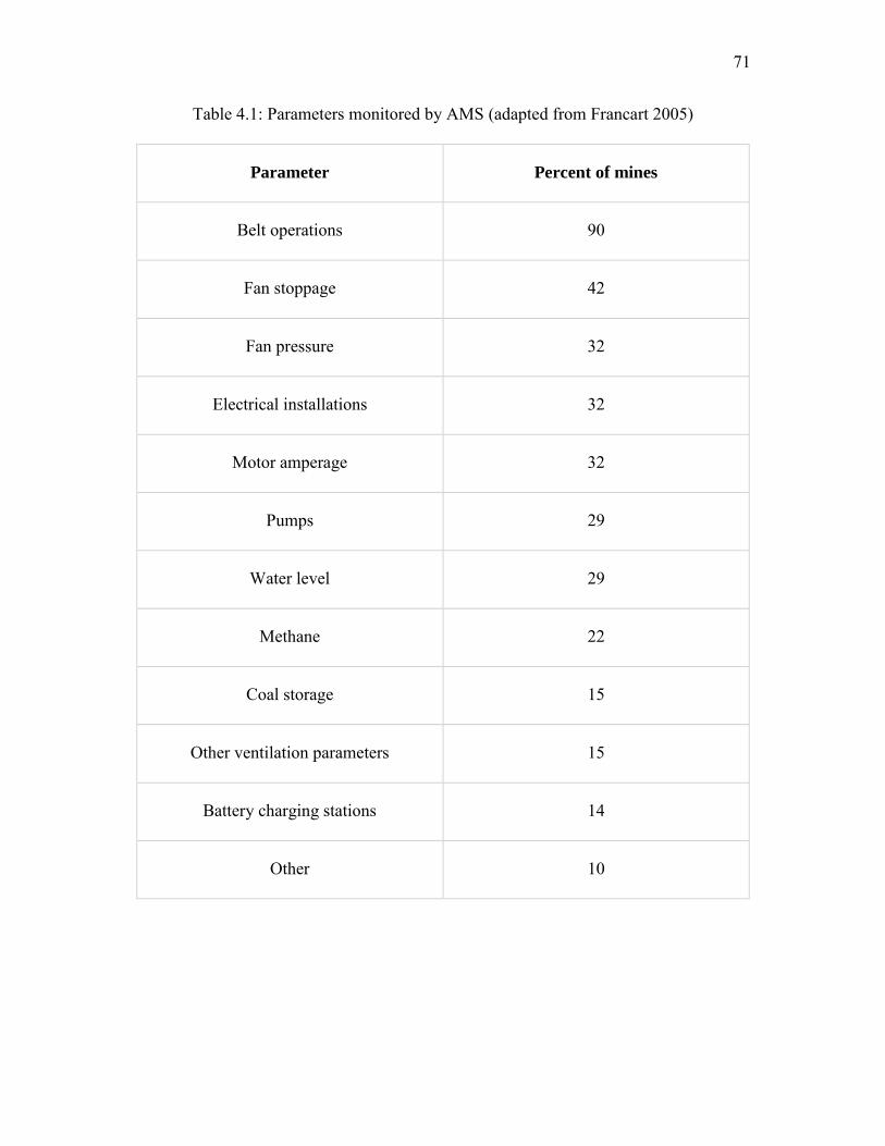
71
Table 4.1: Parameters monitored by AMS (adapted from Francart 2005)
Parameter Percent of mines
Belt operations 90
Fan stoppage 42
Fan pressure 32
Electrical installations 32
Motor amperage 32
Pumps 29
Water level 29
Methane 22
Coal storage 15
Other ventilation parameters 15
Battery charging stations 14
Other 10

72
Table 4.2: Classification of mine gases
Name Hazards
Guideline
TLVs
Methods of
detection
Flammability
Limits
Carbon
Monoxide,
CO
Highly toxic
and explosive
TWA=50
ppm
STEL=400
ppm
Electrochemical,
catalytic oxidation,
semiconductor,
infra-red
12.5 to 74.2%
Methane,
CH4
Explosive;
layering
1%: de-
energize
equipment
2%: remove
personnel
Catalytic oxidation,
thermal conductivity,
optical, acoustic,
flame safety lamp
5 to 15%
Oxygen,
O2
Oxygen
deficiency; may
cause explosive
mixtures with
reactive gases
>19.5%
Electrochemical,
paramagnetic, flame
safety lamp
Supports
combustion;
itself not
flammable
Carbon
Dioxide,
CO2
Promotes
increased rate of
respiration
TWA=0.5%
STEL=3% Optical and infrared
Does not
supports
combustion

73
Figure 4.2: Measuring vibration using a vibrometer
Figure 4.3: Vibration severity chart
Small Fans Large Fans15kW < P ≤ 300kW P > 300kW
Vel
oci
ty
2
0
4
6
8
10
Alert
Alarm
Alert
Alarm
mm/secrms
New machine condition
Long-term operation allowable
Short-term operation allowable
Vibration causes damage
Vibration Severity Chart

74
Figure 4.4: Fan pressure vs. barometric pressure measured in Salt Lake City
84900
85000
85100
85200
85300
85400
85500
85600
85700
2015
2020
2025
2030
2035
2040
2045
2050
2055
2060
2065
Baro
metric P
ressure (P
a)
Fan
Pre
ssu
re (
Pa)
Time(01/31/14 11:30 AM - 02/01/14 08:30 AM)
Fan Pressure vs Barometric Pressure vs Time
Fan pressure Barometric Pressure 50 per. Mov. Avg. (Fan pressure) 50 per. Mov. Avg. (Barometric Pressure)
11:30 AM2.11 mm/sec67 F
06:50 PM5.36 mm/sec95 F
03:50 PM3.05 mm/sec94 F
10:10 PM3.47 mm/sec92 F
01:35 AM3.44 mm/sec93 F
08:30 AM3.46 mm/sec
87 F
74

75
Figure 4.5: Measure of velocity at an underground booster fan
Figure 4.6: Schematic showing the operating principle of an ultrasonic anemometer. ∆S: Sensor face-to-face distance, A: Drift cross-sectional area perpendicular to air flow stream, and L: Distance from Sensor #1 (S1) to Sensor #2 (S2) parallel to the airflow
stream
L
Flow
S1
S2A
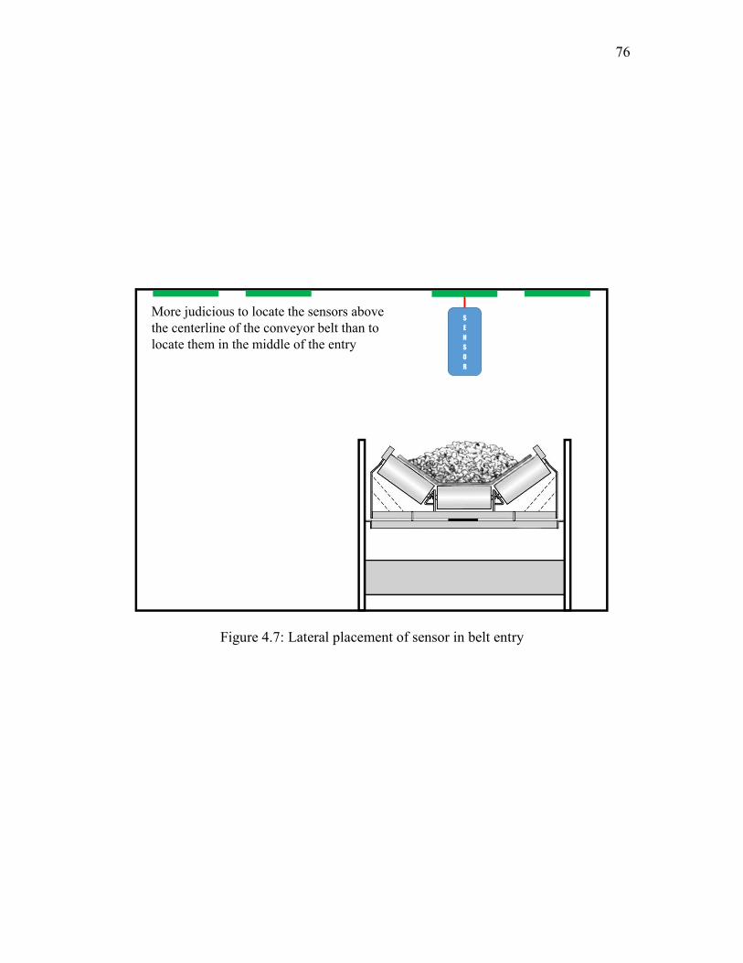
76
Figure 4.7: Lateral placement of sensor in belt entry
S
E
N
S
O
R
More judicious to locate the sensors above the centerline of the conveyor belt than to locate them in the middle of the entry

CHAPTER 5
BOOSTER FAN MONITORING SYSTEMS
As underground mines go deeper and deeper, ventilation conditions may deteriorate
due to the difficulties found in attempting to meet the required airflows. This problem is
even more difficult when the mine is ventilated solely by means of surface fans. At
greater depths coal mining has encountered several problems, including increased gas
emission and heat flow rates, requiring larger quantities of fresh air. Currently, high-
pressure fans are being used to supply these quantities. High-pressure fans often induce
substantial losses of fresh air in the form of leakage. In addition, they require a number
of airlock doors. Booster fans can be used to overcome this problem. The operation of
these units must meet a certain number of requirements including fan condition and
environmental monitoring. In fact, in all coal mining countries, an AMS is an integral
part of the booster fan ventilation system. It is of utmost importance to understand that
booster fans cannot be used in place of main fans at any point.
In this chapter, the experiences of booster fan use in the U.K. and Australia are
discussed followed by design and installation principles of the booster fans. Next, fan
electrical interlocking systems and the importance of uninterruptible power supplies are
discussed in brief detail. The environmental and condition monitoring guidelines are

78
laid out. Finally, risk assessment has been conducted to study the issues associated with
booster fan use, and the subsequent control measures are laid out. Special emphasis was
given to risk assessment because it is one of the most integral parts of designing booster
fan ventilation systems in the U.K. and Australia.
5.1 Introduction
A booster fan is an important component of a mine ventilation system. In practice,
this term is generally used to describe a fan that gives boost to the air current passing
through it. The fan is installed in a permanent bulkhead and equipped with airlock
doors, stoppings, electrical interlocking devices with the main fan, and an atmospheric
monitoring and control system. Considering that the fan is an active device with moving
parts, it is imperative to install it with an efficient continuous monitoring and control
system. This task is accomplished by a modern day monitoring and control system that
can not only monitor and collect data but also control numerous parameters from a
computer terminal at the control room on surface. The parameters monitored at or near
a booster fan may include environmental parameters such as CH4, CO, smoke,
barometric pressure, air velocity and pressure, and conditional parameters such as fan
speed, vibration, motor and impeller bearing temperatures, and electric power.
5.1.1 Sample Installations
In order to understand the principle and design of booster fan installations, six
underground coal mines were visited, three in Australia and three in the United

79
Kingdom, during the course of the project. In these mines, booster fans are used
regularly to overcome adverse conditions created by higher airway resistances and
increased airflow requirements. In each case, booster fans are installed in the return
airway to assist the main fans in delivering the required quantities of air to workings
that are located at great depths, with large CH4 emission rates and under
environmentally sensitive areas. In both countries, booster fans are seen as integral parts
of the mine ventilation design (Calizaya 2014). The installation principles learnt from
these inspections are summarized in two sample installations.
5.1.1.1 Sample Installation I
This installation represents a typical booster fan system in an Australian
underground coal mine. The working areas are approximately 500 m below the surface.
As mentioned above, the fans are installed in the return airways. The system primarily
consists of two double-inlet centrifugal fans installed in concrete bulkheads. The system
is designed to deliver 300 m3s-1 at 3.0 kPa pressure, with the surface fans delivering 320
m3s-1 at 3.2 kPa. The fans are equipped with heavy-duty airlock doors and an
independent fan conditioning and environmental monitoring system (as shown in Figure
5.1). One of the interesting things to see in Australian installations is that, because of
regulatory restrictions, the fan motor is required to be ventilated by fresh air all the time
(Benson 2002). As a result, the fan motor must be located in a specially designed, fire
resistant chamber, which is ventilated with fresh air by two separately routed, 30-cm-
diameter pipes. The heavy-duty airlock doors are used in series; sometimes an
installation can have more than two airlock doors in series. These doors are capable of

80
withstanding high pressure differentials and are used to allow machine access to the fan
site and to minimize recirculation. The booster fan system is equipped with condition
monitors and environmental monitors located upstream and downstream of the booster
fan and in the motor chamber. The factors that are monitored include differential
pressure, air flow rate, smoke sensors, and CH4 and CO concentrations. From a safety
point of view, the system is equipped with an independent power supply routed from
the surface through a borehole. A site specific operating procedure is used to start and
stop the fans and to avoid the onset of unwanted flow recirculation. The fact of that the
surface fan capacities are larger than those of the booster fans reduces the possibility of
flow recirculation.
5.1.1.2 Sample Installation II
Figure 5.2 shows a schematic of a booster fan installation in a British underground
coal mine with significant flow requirements. In this mine, the workings are located at
about 1000 m below the surface, where the rock temperature may be as high as 42ºC. In
addition, the mine uses a substantial amount of water to control dust and to cool the
mining machinery. The booster fan system consists of a single 1500-kW axial fan
installed in the main return airway, near the neutral point. The motor, also located in the
return airway, is protected by a fireproof enclosure. The fan is equipped with a set of
heavy duty airlock doors to reduce flow recirculation and a system that monitors the
operating condition of the fan. Because of high pressure differentials across the
stoppings, four heavy duty airlock doors are used to isolate the fan from the intake
entries. The factors that are monitored include differential pressure, flow rate, motor

81
and bearing temperatures, vibration, and CH4 and CO concentrations. The fan system is
designed to deliver 160 m3s-1 at 7.0 kPa pressure with the surface fans delivering 280
m3s-1 at 5.5 kPa. A site specific safe operating procedure is used to start and stop the
fans and the mining machinery near the fan. Although series ventilation is discouraged
because of the high pressure differentials across the stoppings, some recirculation (<
10%) is allowed (Leeming 2012). In this mine, booster fans are viewed as an essential
component of the ventilation system. Other alternatives such as sinking a new shaft and
upgrading the main fans have been considered, but all were rejected because they were
not as effective or economic as the booster fans in providing adequate air volume to the
workings.
A comparative analysis of use of booster fans in UK and Australian coal mines is
presented in Table 5.1.
5.2 Design and Installation Principles
Booster fan installation may require development of a bypass drift, widening of an
existing drift, installation of stoppings, and miscellaneous civil constructions. The drifts
should be widened as recommended by the fan manufacturer. They should provide
ample space to house the fan assembly, an overhead monorail, man doors, and fan
condition monitoring components. In coal mines, booster fans are generally located in
the return way in the straight section of a drift or a bypass drift and are equipped with
airlock doors and stoppings. When multiple fans in parallel are used, each fan must be
equipped with self-closing doors. Bulkheads and doors should be designed to reduce
leakage and to withstand high pressure differences.

82
The concept of bypass drift can also be utilized to control the problem of
spontaneous combustion near the fan. Figure 5.3 shows an installation of a booster fan
in a bypass drift developed in the overlying strata. This is generally made up of
sandstone or shale, which minimizes the chances of spontaneous combustion, increases
the stability, and provides a route for the machinery to move across the fan if there is a
problem.
Another simpler but less effective method to deal with the problem of spontaneous
combustion near the fan installation is to grout the roof, walls, and floor around the
installation (Figure 5.4). This is generally done for 30 m upstream and downstream of
the fan. It helps in controlling the spontaneous combustion up to a certain level. It
should also be noted that the fan motor should be enclosed in a flameproof enclosure. If
something goes wrong with the motor such as sparks or fire, it should be contained
within the enclosure. This is mostly required when axial fans are used.
Another important aspect of booster fan installation is the selection of the right type
of fan, preferably custom made. The type of installation is dependent on the type of fan.
Generally, axial fans operate at lower pressures and deliver higher quantities of air,
whereas the centrifugal fans operate at higher pressures and deliver lower quantity.
Booster fans are used underground to overcome the high resistance of the mine by
assisting the main fan in delivering the required quantity of fresh air at the working
areas. It is therefore recommended to use centrifugal fans as booster fans. Another
reason why centrifugal fans should be preferred over axial fans is that the motor does
not need to be in-line with the fan as in the case of axial fans. In centrifugal fan
installations, the motor is placed in a chamber next to the fan; this chamber is ventilated
83
by fresh air at all times. The fresh air ventilates the chamber through ~30-cm steel ducts
connected to the intake airway (Figure 5.1). This reduces the chances of fire or other
major problems in the underground (Benson 2002). As booster fans are installed in
return airways, centrifugal fans are the better option. If axial fans are used, the motor
and all electrical components need to be enclosed in a flameproof housing. Flameproof
is a theoretical term since from a practical point of view, nothing is flameproof. It can
withstand the pressure up to a certain level. Even after flameproof enclosure, an
explosion or fire could take place near the fan installation.
A few more recommendations are also made related to installation of booster fans
underground. Most mine pillars are square or rectangular in shape, which leads to
higher shock losses near booster fans in return airways. In general, booster fans are
permanently installed in one or two return airways, and the air from other entries is
directed to them. It is, therefore, recommended to have special designs such as
trapezoidal shaped pillars with a 45-degree crosscut angle to minimize the shock loss
(Figure 5.5). It will also be worthwhile to have longer pillars and wider drifts where
booster fans are to be installed. This will help in streamlining the flow and reducing
shock losses but will also lower the air leakage through crosscuts. Most leakage takes
place through the 10–12 crosscuts near the fan (Miles 2010). Hence, increasing the
pillar size would lower the amount of air leakage and uncontrolled recirculation.
5.3 Basic Monitoring Requirements in Coal Mines
Monitoring is the process of measuring environmental and fan operating factors to
evaluate and predict the health and safety conditions in the mine. When booster fans are

84
used in coal mines, a mine monitoring system is a basic requirement, not only to
determine the operating status of booster fans but also to ensure that it is being used
safely and efficiently. Monitoring systems have been used in the mining industry for
almost 4 decades. The use of these units in U.S. coal mines began in 1976 when, for the
first time, belt entry was used to ventilate the face with fresh air. This section is
subdivided into two major subparts: condition monitoring and environmental
monitoring.
5.3.1 Condition Monitoring
A well-maintained and low-cost mining operation requires the use of condition
monitoring techniques. Condition monitoring is the process of measuring fan operating
factors to evaluate and predict the health and safety conditions of the mine fans. An
adequate and reliable condition monitoring system is quintessential for a mine using a
booster fan ventilation system. This includes the measurement and evaluation of the
following variables at booster fans: vibration, noise, power, bearing temperature,
differential pressure, and quantity. They are used to diagnose the health of the fan.
These parameters are briefly discussed in this section and are discussed in greater detail
in Chapter 4.
5.3.1.1 Vibration
Vibration analysis is a powerful tool to assess the performance of main and booster
fans. Variations in normal operating conditions of mine fans produce significant
85
changes in vibration levels and causes wear or deterioration of the fan. After reviewing
the current literature on vibration monitoring, it is recommended to have at least six
vibration monitors (velocity type): two for the fan fixed bearing, one for fan floating
bearing, two for the motor non drive end, and one for the motor drive end. The
application of this type of monitoring is somewhat limited in predicting potential
failures. Acceleration-type vibration monitors are recommended for this purpose
(Jorgenson 1999).
5.3.1.2 Bearing Temperature
Bearings are the most critical components of main fans. Bearing temperature is one
of the most reliable indicators of the status of the fan. Bearings are important parts of
the fan assembly because they must withstand the loads due to the dead weight, thrust,
and unbalance of the rotor assembly. They must also be able to operate at the intended
speed without overheating. Each 10°C increase in operating temperature shortens the
motor life by 50%. High bearing temperatures indicate problems related to fluid-film,
including overload bearing fatigue, and insufficient lubrication. Under normal
conditions, the bearings should be maintained at temperatures of less than 85°C (Snaith
1998).
5.3.1.3 Air Pressure and Quantity
Booster fans are one of the most important entities of a mine; therefore, it is
essential to continuously monitor their duties, that is, fan pressure and flow rate.
86
Commonly, fan pressures are measured by means of manometers and the flow rates by
measuring the air velocity and the cross-sectional area of the airway. Fan static
pressures are monitored by means of differential pressure transducers that are easily
interfaced with a mine-wide monitoring system. The differential pressure is monitored
across the bulkhead and airlock doors. Air velocities are monitored by means of a Pitot
tube and manometer, ultrasonic anemometer, or a vortex shedding anemometer. The
pros and cons of the application of these instruments were discussed in greater detail in
Chapter 4. The main problem here is the location of the monitor in the airway to record
an average velocity. Commonly, velocity transducers are located near the roof, thus
collecting point velocities. Then these are corrected (calibrated) using hand-held
instruments. Other types of sensors are seldom used in coal mines. Another important
aspect of measuring the air flow near the underground booster fan is the location of the
monitor relative to the fan. It is recommended to place the monitor at a distance
equivalent to 2–4 diameters on the intake side and 6–10 diameters distance on the
exhaust side of the fan as shown in Figure 5.6. Results are expressed as flow rate.
5.3.1.4 Booster Fan Noise
Noise is sound that is unwanted or disturbing. The sound emitted by a fan is an
inevitable by-product of the energy-transfer process. Because most fan sound is
unwanted, it is classified as noise. Fan noise increases with both flow rate and specific
output. However, selecting the fan operating point properly so that the fan operates at its
quieter points of rating will minimize noise. Noise is an important factor and is
discussed in detail in the Code of Federal Regulations (CFR). It is recommended to

87
continuously monitor noise near the booster fans. The noise pattern along with vibration
patterns is a good sign to know if there is something wrong with the fan.
5.3.2 Environmental Monitoring
Monitoring of environmental parameters near the booster fans in underground is
critical to the health and safety of the miners particularly in a large mine. The multitude
of interacting parameters that can favorably or adversely affect the environmental status
makes the manpower requirement of the routine checking of specific areas and
conditions a formidable one. Mining operations around the world, especially in large
deep coal mines using booster fans, rely upon monitoring systems to provide miner
safety by monitoring CO, CH4, smoke, and several other parameters. From the
inspection in Australian and British coal mines, as discussed in sample installations, a
number of principles were learnt for optimal design of monitoring system. The location
of monitors and monitor parameters is explained with the help of Figure 5.1 and 5.2.
More details on the type of monitors and their pros and cons are discussed in Chapter 4
and Appendix A.
5.3.2.1 Carbon Monoxide
Carbon monoxide (CO) is a colorless, odorless, and tasteless gas that is slightly less
dense than air. The high toxicity of CO coupled with its lack of smell, taste, or color
make this one of the most dangerous and insidious of mine gases. The high toxicity of
CO makes it very important to have a good monitoring system for continuous

88
monitoring. Since CO is one of the first products of combustion, it also acts as a
parameter for early detection of fire underground. CO detectors are designed to measure
the gas levels over time and sound an alarm before dangerous levels of poisonous gases
accumulate in an environment, giving people adequate warning to safely ventilate the
area or evacuate. The common sensors that are used for detection of CO are based on
catalytic oxidation, electrochemical reaction, and infrared absorption principles. After
carefully reviewing all the sensing principles, it is recommended to use the monitors
based on the infrared absorption principle near the fan as the primary monitor for CO.
The monitor should be placed approximately 4–6 diameter lengths away from the fan
on the exhaust side. It is placed after the fan so that if there is a fire in the fan
installation, it can be detected early by this monitor. Monitors based on the optical
methods are highly sensitive, selective, and stable. Although they are expensive, they
have a long lifetime that would call for fewer inspections and troubleshooting. As for a
redundant monitor, it is recommended to have a monitor based on electrochemical
principles used traditionally in mines. One of the major disadvantages of
electrochemical analyzers is that they can become temporarily saturated when exposed
to high concentrations of gas. The recovery period may be several minutes. However, as
a redundant monitor they are a good choice because they can indicate the concentration
of CO if infrared monitors do not work in case of a large fire. They must be calibrated
regularly.

89
5.3.2.2 Smoke
Smoke is an aerosol that is formed by incomplete combustion and ordinarily
consists of particles 0.01–1.0 micrometers in size. Smoke particles are usually visible
and distinguished from fumes by the fact that they do not result from the condensation
processes. Using smoke sensors for environmental monitoring is mentioned in the CFR.
Smoke is one of the products of combustion and acts as a good indicator of a fire
underground.
Smoke sensors can be more sensitive to the early detection of mine fires than the
CO sensors currently used in most AMS systems (Edwards 2003). Smoke sensors can
be classified into two types based upon their operational principle: ionization and
optical. Ionization sensors are more sensitive to the smaller smoke particles associated
with flaming combustion, whereas optical sensors are more sensitive to larger smoke
particles associated with smoldering combustion. The advantages of smoke sensors over
CO sensors for early warning is partly due to the origins/mode of the conveyor belt
heating/fire and the materials involved (e.g., producing significant smoke but little CO).
It is obvious that multiple sensor types, used in combination, could provide earlier and
more reliable detection. Multiple sensors (CO and Smoke) should be used near the
booster fan. In the case of a conveyor fire, the smoke sensor should go off before the
CO sensor, which is a good indication that there may be conveyor fire and not fire in the
fan installation.
90
5.3.2.3 Methane
Methane is one of the most common strata gases. It is produced by bacterial and
chemical action on organic material during the formation of coal. Methane is not
particularly toxic but it is flammable and can form explosive mixtures with air. This has
resulted in the fatalities of many thousands of miners. As shown in Figure 5.1 and 5.2,
CH4 is monitored upstream and downstream of the fan. This enables the AMS operator
to know if the fire is in the fan installation or in other parts of the mine. The common
sensors that are used in monitoring methane are based on the principles of catalytic
oxidation and thermal conductivity. The details of these monitors can be found in
Appendix C. When the methane concentration at any methane monitor reaches 1% the
monitor shall give a warning signal. As learnt from experience from the mines in the
U.K., it is recommended to permit the operation of booster fans up to 1.25% methane.
At levels above this the fans must be shut off. At 1.8% methane development should be
halted and at 2% methane all personnel should be withdrawn from the mine. According
to 30 CFR § 75.342, when the methane concentration at any methane monitor reaches
1.0% the monitor shall give a warning signal. The warning signal device of the methane
monitor shall be visible to a person who can de-energize electric equipment or shut
down diesel-powered equipment on which the monitor is mounted. This shall be done
automatically if the methane concentration at any methane monitor reaches 2.0% or if
the monitor is not working properly.

91
5.4 Number, Location, and Type of Monitors
The key to an efficient and reliable monitoring system is selecting the right type and
number of monitors and placing them at optimum locations. There is no absolute rule
for the type or number of monitors for booster fan installations; it depends on the
specific installation and conditions of the mine. Some recommendations are made in
section 4.6.2 for optimum placement and spacing of monitors. Monitoring of fan and
environmental parameters near a booster fan installation underground is critical for the
health and safety of the miners.
For condition monitoring, the parameters that need to be monitored are vibration,
noise, differential pressure, airflow, electrical power, and motor and bearing
temperatures. For monitoring vibration, six vibration monitors are required (velocity
type); two for the fan fixed bearing, one for fan floating bearing, two for the motor non
drive end, and one for the motor drive end. This recommendation is valid for both axial
and centrifugal fans. Noise should be monitored near the fan at all times; fluctuations in
noise are a good indication of a malfunction in the fan. Also, proper hearing protectors
should be used if somebody had to go near the fan as booster fans create a lot of noise.
Dosimeters are used for monitoring noise. The differential pressure is measured across
the bulkhead, nearest airlock doors, and across the intake and return airway at the
nearest stopping. Airflow is probably the most important parameter that needs to be
monitored continuously underground. It is recommended to place the monitor at a
distance of 6–10 drift diameter lengths away on the exhaust side of the fan or 2–4
diameter lengths away on the intake side (Daly 1992). The airflow readings on the
intake side of the fan are more reliable because the flow is less turbulent compared to

92
that on the exhaust side of the fan. Electrical power is another important parameter that
needs to be monitored really well. Booster fans have an independent power supply
separate from the other equipment in the mine. Monitoring power gives a good
indication of the efficiency of the fan. Motor and bearing temperatures should be
monitored continuously; they are a good indicator of any malfunction in the fan
installation. Booster fan installation should have four temperature probes on the
bearings; two on motor and two on fan along with amperage monitoring of the motor.
For environmental monitoring, the parameters that need to be monitored are carbon
monoxide, smoke, and methane. Redundancy is also very important for a reliable
environmental monitoring system. Since monitors are placed in harsh environments
with lots of heat, humidity, and dust, a number of things can go wrong in a monitor.
Therefore, it is essential to have redundant units especially near the booster fan
installation. It helps the AMS operator and mine management in making decisions with
a greater confidence level, in case of an emergency. The monitoring sensors are limited
by the sensing technology used to detect the parameters of interest. Most commercially
available gas sensors have response times averaging between 10 and 30 seconds.
Catalytic gas sensors used for monitoring CO and CH4 range from 10 to 15 seconds,
and IR sensors used for monitoring CO and CO2 range from 15 to 30 seconds (Griffin
2012). In addition to these sensing timings, additional time is required for transmitting
the data to the surface and processing it, followed by making a logical decision. These
times may not be adequate to de-energize booster fan and equipment downstream in
rapidly changing atmospheres and may allow for movement of equipment well into an
explosive atmosphere. For monitoring carbon monoxide, it is recommended to use

93
monitors based on the infrared absorption principle near the fan as the primary monitor
for CO. The monitor should be placed approximately 4–6 diameters away from the fan
on the exhaust side. It is placed after the fan so that if there is a fire in the fan
installation, it can be detected early by this monitor. Monitors based on the optical
methods are highly sensitive, selective, and stable. As for redundant monitors, it is
recommended to have a monitor based on electrochemical principles used traditionally
in mines. As a redundant monitor they are a good choice because they can indicate the
concentration of CO if infrared monitors do not work in case of a large fire. In addition
to CO, smoke sensors should also be used near the fan installation. They can be more
sensitive to the early detection of mine fires than the CO sensors. The advantages of
smoke sensors over CO sensors for early warning is partly due to the origins/mode of
the conveyor belt heating/fire and the materials involved, e.g., producing significant
smoke but little CO. For methane, it is recommended to have monitors based catalytic
oxidation principle as primary monitor because they are heavy duty and can accurately
measure concentrations within the 0–5% range. As a second monitor, monitors based on
thermal conductivity should be used since they are good for a range from 5–100%. This
sort of arrangement both before and after the fan not only gives the indication of the fire
but also provides information on the scale of the fire or explosion in greater detail. As
far as lateral and vertical spacing is concerned, all the monitors should be placed in the
center of the drift and at a distance of 1 to 2 ft from the roof.
All these monitors should be connected to the surface control room where all the
levels are computer monitored. Preset alarm conditions should be listed on screens with
an alert for the operator and visually displayed on schematics.

94
5.5 Fan Interlocking System
Interlocking is a method of preventing the occurrence of any unsafe condition,
which in a general sense can include any electrical, electronic, or mechanical problem
in the mine ventilation system. The simplest example of fan interlocking is that if the
main fan shuts off due to power failure or any other problem, the booster fan and all the
mining equipment should automatically switch off to prevent any kind of uncontrolled
recirculation in the mine. Most mines use electrical interlocking with the AMS so that if
high concentrations of gas are detected, electrical equipment downstream is de-
energized and the booster fans are disabled to allow flow through ventilation and
prevent the recirculation of contaminants (Burton et al. 1986). Main and booster fans
are operated as long as the workers are in an underground mine. The monitoring system
measures all the relevant parameters including the concentrations of air contaminants.
The booster fan is equipped with an interlocking device to cut off the power to the fan
in the event of main fan failure. If a booster fan fails for any reason, the equipment
nearby must be de-energized and the airlock doors must open automatically. This action
is performed to prevent the build-up of air contaminants. If the main fan fails for any
reason, the booster fan and all underground equipment must be de-energized. Under this
condition, the whole system is down and an alarm must be generated. That alarm may
be generated automatically or by a management procedure. Alternatively, a redundant
main fan is used as in the U.K. Workers must be trained to understand that, in the
instance of such an alarm, the mine’s emergency evacuation procedure is initiated. A
fan start-stop protocol is to be established to restore power after any power stoppage,
including those scheduled for changing the fan duties.
95
In order to come up with proper recommendations for fan interlocking, practices in
the U.K. and Australia were reviewed. In Australia, booster fans are used in two coal
mining states: New South Wales (NSW) and Queensland (QLD). In both the states, fan
interlocking is part of the regulations. The underground mines in Australia are
shallower (~500 m) compared to mines in the U.K. Therefore, it is not difficult to have
a fan interlocking in place. It is a common practice in Australia to have ventilation
boreholes. These boreholes are also used for providing an independent power line for
the booster fan. Most Australian mines have centrifugal fans over axial fans, mainly
because of their high pressure requirements. Recirculation is not permitted in the
Australian mines; therefore, to prevent any uncontrolled recirculation or gas build up,
fan interlocking is used. The airlock doors are opened if the booster fan turns off due to
any problem. In case the main fan shuts off, the booster fans are switched off
automatically (Coal Mine Health and Safety Regulation 2006).
In the United Kingdom, electrical interlocking between the main and booster fan is
not required (The Coal and Other Mines (Ventilation) Order 1956). The coal mines in
the U.K. are very deep (In the order of 800–1000 m). Therefore, it is difficult to have an
interlocking system. Booster fans are accepted as a necessary tool for adequate mine
ventilation. In several mines in the U.K., booster fans are recognized as the only
feasible option for providing adequate air velocity and quantity to the active work areas.
In order to prevent any uncontrolled recirculation or gas build up in the underground
because of failure of the main surface fan, mines in the U.K. have a redundant surface
fan. The two fans have different power supplies so that if the primary fan fails, the
redundant back up fan can be switched on. The redundant fan may not have the same

96
capacity and may or may not provide the equal amount of air as provided by the
primary surface fan, but it still serves the purpose of buying time for miners to take
shelter in a rescue chamber and move mine equipment to a safe place if possible.
Meanwhile, the problem in the primary fan can be resolved. The booster fan cannot be
controlled from the surface directly; it has to be manually switched off or on by a
competent person in the underground. When the booster fan is switched off, the airlock
doors are opened. Booster fans can be installed in a ventilation system without any
special application to the Mine Inspectorate, but a person must monitor them every half
hour. In order to extend the fan inspection time to 8 hours, the mine must use a robust
environmental and fan monitoring system and apply to the Inspectorate for an
exemption.
The recommended design of the fan interlocking system can be seen in Figure 5.7.
Different equipment, fans, airlock doors, and AMS are connected to a central electric
interlocking system. This system not only provides an interlock between the main fan
and booster fan, but also includes other mine equipment, airlock doors, and AMS.
Firstly, on the surface, it is recommended to have two main fans. The two fans may or
may not be of the same capacity. These fans should have independent power supplies
from each other. One is used as a primary and the other is always used as a redundant
fan. As shown in the figure, if the primary fan fails due to some reason, it sends a signal
to the electric interlocking system that in turn sends a signal to the redundant fan and
switches it on. The redundant fan may or may not provide the same quantity of air as
delivered by the primary fan. Secondly, the booster fan can both send and receive a
signal from the electric interlocking system. If the primary fan fails, the booster fan
97
should be turned off immediately, and the airlock doors should be opened automatically
to prevent any kind of uncontrolled recirculation or gas build-up. When the redundant
fan is switched on, the booster fan may or may not be used depending on the ventilation
conditions and fan duty of the redundant fan. Thirdly, the electric interlocking system is
also connected to the AMS so that if high concentrations of gases are detected, the
booster fans can be turned off accordingly to prevent any disaster from happening. In all
the cases, the mining equipment and machinery nearby (longwall, continuous miners,
shuttle cars, etc.) shall be de-energized automatically. This pattern of electric
interlocking can prevent most of the problems in the mines related to the use of booster
fans in underground.
5.6 Uninterruptible Power Supply
An uninterruptible power supply, UPS, is an electrical apparatus in a mine that
provides emergency power to mine fans and other electrical equipment when the input
power source, typically main power, fails. A UPS differs from an auxiliary or
emergency power system or standby generator in a way that it will provide near-
instantaneous protection from input power interruptions by supplying energy stored in
batteries or a flywheel. The on-battery runtime of most uninterruptible power sources is
relatively short (only a few minutes) but sufficient to start a standby power source or
properly shut down the protected equipment. A UPS is typically used to protect
hardware such as monitoring systems, data centers, communication equipment, mine
fans, or other important electrical equipment in the mine where an unexpected power
disruption could cause injuries, fatalities, serious business disruption, or data loss.
98
The primary role of any UPS is to provide short-term power when the main power
source fails. However, most UPS units are also capable in varying degrees of correcting
common utility power problems like voltage spikes or sustained overvoltage,
momentary or sustained reduction in input voltage, noise, defined as a high frequency
transient or oscillation, usually injected into the line by nearby equipment, instability of
the mains frequency, etc. It is very important to have UPS as an integral part of the
booster fan ventilation system because power failure can lead to disastrous conditions
such as uncontrolled recirculation or gas build up along with monitoring systems down
for a few minutes.
5.7 Risk Assessment of Monitoring Systems
Risk assessment is the process by which the outcomes of risk analysis are compared
against the risk acceptance criteria established for this purpose and understood by all
parties. If requirements are not met, changes to the system should be made and the
process is repeated until the requirements are met. Risk assessment has many powerful
tools that can identify hazards associated with the operation and maintenance of booster
fans and the AMS in the mine. It analyzes the accompanying risks and recommends
control measures to reduce those risks to acceptable levels. The hazards associated with
the operation of monitoring systems were identified, the risks analyzed, and the
response to each failure mode was established.
Although mine monitoring systems are assembled and installed to operate under
harsh conditions, they are subject to wear and tear and malfunction. The system
components should be maintained regularly, and the sensors must be calibrated against
99
primary standards. Furthermore, the system must be equipped with redundant units. If
the system provides erroneous readings, fan conditions cannot be predicted and the
failure modes cannot be avoided. Gas sensors, pressure transducers and other devices
used with a monitoring system are subject to wear and malfunction. Using faulty units
can result in unsafe and unhealthy conditions. To overcome the problem, transducers
should be calibrated frequently. Redundant units and uninterruptable power supplies
should be provided for critical monitors. The same is true for condition monitoring
parameters such as motor and bearing temperatures. The fan motor and bearings may
fail under high load beyond their rated power. The motor and bearing temperatures are
key indicators of the fan health. When the fan is installed properly, with the right
alignment, these temperatures should never exceed the alarm level, which is typically
85ºC. However, these temperatures may vary with weather conditions.
5.7.1 Risk Matrix
The risk matrix is an evaluation tool used to rank the risk of a potential hazard in
terms of the likelihood (L) and consequence (C) of the undesired events. It increases the
visibility of the risk and assists the management in making timely, informed decisions
(Chapanis 1986; Grayson 2001). Table 5.2 shows the risk matrix used in this study.
Work Place Risk Assessment and Control (WRAC) is a qualitative risk ranking
method (as shown in Table 5.3). It breaks down the work into steps in a process map
and evaluates each unwanted event using a risk matrix. A WRAC analysis was
performed for the installation and use of booster fans and its monitoring system
(Calizaya 2014).

100
5.7.2 Bow-Tie Analysis for Booster Fan Ventilation Systems
Risk assessment of the booster fan ventilation systems was conducted using bow-tie
analysis. The analysis was conducted as a part of a process designed to ensure that the
hazards relating to booster fan system safety are being managed appropriately in order
to render the associated risks to an acceptable level to all workers, management, and
stakeholders.
Bow-tie analysis is an extremely powerful tool for assessing and managing the risks
associated with operations in mining, machinery use, etc. It is simple to use and can be
used for a wide variety of risks. It can be used to assess work-place conditions and
workers’ behavior. It produces a clear picture of cause-consequence relationships and
helps producing risk registries. Unlike traditional risk evaluation tools, the bow-tie
method makes the link between risk controls and the health safety and management
systems. However, it is difficult to link this analysis to other quantitative techniques.
The analysis began with the scoping process, which basically means assessing the
risks associated with booster fan ventilation systems. The objectives, scope, and breadth
of the risk assessment were defined in this step. Identifying the different threats to the
system and consequences associated with them that would lead to malfunction of the
booster fan ventilation systems followed this.
The threats related to the operation of the booster fans were identified with the aim
of establishing appropriate control measures and in turn booster fan operation protocol.
The different threats identified are loss of mine power, failure of the main fan, failure of
the booster fan, failure of airlock doors, failure of monitoring system, and spontaneous
combustion. The control measures to each of the threats identified were developed

101
through a process defining operating conditions existing prior to the threat and the safe
operating conditions subsequent to the threat. The control measures are summarized for
each of the threats respectively (as shown in Figure 5.8).
The consequences are identified based on previous experiences and experience of
other mines utilizing the booster fans ventilation systems. Recovery measures
corresponding to every consequence can be seen in the bow-tie analysis chart (Figure
5.8). The major consequences are build-up of air contaminants, uncontrolled
recirculation, fire in fan housing, reduction of total quantity of air delivered, and
unavailability of monitoring data. Some of the control and recovery measures to deal
with the threats are removing power from booster fans, opening by-pass doors, de-
energizing equipment, redirecting air, adjusting regulators, etc.
Under current regulations, booster fan research in the U.S. is challenging due to
nonexistent options for field studies. Computer simulations, laboratory studies, and
comparison to metal and nonmetal mines are the only available tools for research.
Research, experiences, and regulations of other countries present important
comparisons for the potential use of boosters in the US. The use of booster fans can
facilitate continued operation of a mine that is being considered for closure. Booster
fans when installed with proper bulkheads, an efficient and reliable monitoring system,
and sizing and position work normally just like any other fan in a mine.

102
Figure 5.1: Installation of booster fans in Australian coal mines
Figure 5.2: Installation of booster fan in U.K. coal mines
Fan and Environmental Monitors
Tube Bundle Methane Delta Pressure
Booster Fan
Double Bypass Doors
30 cm D
iam. Pipe
Intake
Intake
Return
Return
Fan and Environmental Monitors
Tube BundleMethane
Carbon MonoxideManometer
SmokeDelta Pressure
Man Doors
To TailGate
Bulkhead
Return
Intake
Booster Fan
Airlock Doors

103
Table 5.1: Use of booster fan in U.K. and Australian coal mines—comparative analysis
Description Australia United Kingdom
1. Regulations Coal mine operators are
allowed to use booster fans
to assist main fans in
Australian mines
Booster fans are accepted as safe
and effective ventilation control
devices in underground coal mines
2. Reasons for
using booster fans
Because of mine depths (±
500 m), remoteness of
workings, and
economic reasons
Because of mine depths (> 800 m)
and increased resistance, to
decrease effective mine resistance,
and economic reasons
3. Basic
Requirements
Fan installation plan
approved by Mine
Inspectorate
Installed in concrete
bulkhead
Multiple airlock doors
Set of fan controls and
monitors
Safe operating procedure
(SOP) for each fan
Maintenance every four
months
Need demonstrated through
studies to mine inspector and
results included in the
ventilation plan
Installed in concrete bulkhead
and equipped with airlock doors
Fan condition and
environmental monitoring
system
Fan examination every 30 min*
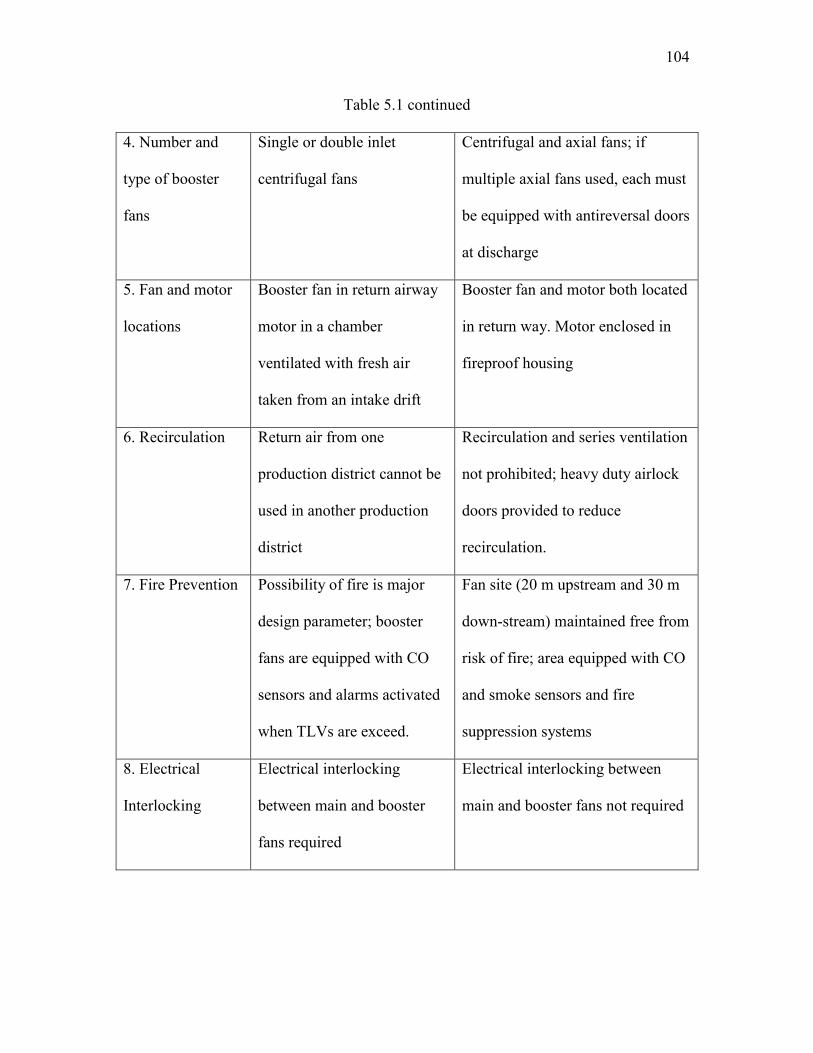
104
Table 5.1 continued
4. Number and
type of booster
fans
Single or double inlet
centrifugal fans
Centrifugal and axial fans; if
multiple axial fans used, each must
be equipped with antireversal doors
at discharge
5. Fan and motor
locations
Booster fan in return airway
motor in a chamber
ventilated with fresh air
taken from an intake drift
Booster fan and motor both located
in return way. Motor enclosed in
fireproof housing
6. Recirculation Return air from one
production district cannot be
used in another production
district
Recirculation and series ventilation
not prohibited; heavy duty airlock
doors provided to reduce
recirculation.
7. Fire Prevention Possibility of fire is major
design parameter; booster
fans are equipped with CO
sensors and alarms activated
when TLVs are exceed.
Fan site (20 m upstream and 30 m
down-stream) maintained free from
risk of fire; area equipped with CO
and smoke sensors and fire
suppression systems
8. Electrical
Interlocking
Electrical interlocking
between main and booster
fans required
Electrical interlocking between
main and booster fans not required

105
Table 5.1 continued
9. Risk Analysis Each mine must develop and
implement appropriate H&S
management system, to
ensure that risks are assessed
and controls are in place at
all times
No fan (not being an auxiliary fan)
shall be installed at any place
below ground unless the manager
is satisfied that it is necessary to
install it at that place for proper
ventilation of the mine
*: Mine inspector has the power of exemption for all aspects of mining law.
Figure 5.3: Booster fan installation in the roof (section view)
Figure 5.4: Shotcreting near the booster fan installation
Coal
Shale/Sandstone
Return Airway
Booster Fan
Airlock Doors
CoalShale
ShotcretingReturn Airway

106
Figure 5.5: Conceptual design of booster fan installation and monitoring system
Figure 5.6: Location of monitor for air flow measurement
Fan and Environmental Monitors
Tube BundleMethane
Carbon MonoxideManometer
SmokeDelta Pressure
Shotcreting
Airlock Doors
Booster Fan
Booster Fan
Return
Return
Return
Before the fan2-4 Diameters
After the fan6-10 Diameters
Monitors

107
Figure 5.7 Schematic of interlocking system
INTERLOCKING
SYSTEM
Longwall
Continuous Miner
Airlock
DoorsAMS
Booster Fan
Surface Fan
(Primary)
Surface Fan
(Redundant)
Power Supply
(Redundant Fan)
Power Supply
(Primary Fan)
Surface
Underground
Incoming
SignalOutgoing
Signal
Power Supply
(Booster Fan)
107

108
Table 5.2: Risk matrix
Severity Insignificant (1) Minor (2) Moderate (3) Major (4) Catastrophic (5)
Likelihood Risk Rating
Most Certain (5) 5 10 15 20 25
Likely (4) 4 8 12 16 20
Poosible (3) 3 6 9 12 15
Unlikely (2) 2 4 6 8 10
Rare (1) 1 2 3 4 5
Risk Rating Guidelines for Risk Matrix
15 to 25 Eliminate or Avoid and Implement Action Plan
9 to 12 Proactive Manage
4 to 8 Actively Manage
1 to 3 Monitor & Manage
Categories of harm severity Categories of harm likelihood
Catastrophic Multiple deaths Most Certain Occurs once or twice in a year
Critical Death or multiple severe injuries Likely Occurs less than once in a year
Moderate 1-3 severe injuries Possible Occur or may re-occur in 10 years
Minor Severy injury or multiple minor injuries Unlikely Can happen in 20 years
Insignificant Minor injury Rare Has never occurred before
108

109
Table 5.3: WRAC analysis and outcomes
Steps in process Unwanted
Event
Current
Controls L C R Recommendation
Failure to design
monitoring
system
Undetected
fire and
recirculation
Use hand
held units to
monitor CO
3 4 12
Follow the good
practices as
adopted in other
country
Failure to design
airlock doors and
bulkhead
Airlock
doors fails to
open, or
close
Test airlock
doors for
stability
2 4 8
Follow the good
practice as adopted
in other country.
Failure to
measure vibration
and temperature
Damage to
motor and
fan parts
Fan
monitoring
system
2 4 8 Check manually,
redundant sensors.
Mechanical or
Electrical fault
Failure of
electrical
interlocks
Fans
installed in
same circuit
1 5 5
Independent power
sources for main
and booster fans
Failure of
monitoring
system
Check air
quality
manually
2 4 8 Install redundant
monitoring
Failure of
motor
Regular
maintenance 2 4 8
Keep spare motor
and fan parts

110
Figure 5.8: Bow-tie analysis chart
Loss of Mine
Power
Failure of
main fan
Failure of
booster fan
Failure of
monitoring
system
Spontaneous
Combustion
Build Up of
Air
Contaminants
Reduction of
Total
Quantity of
Air Delivered
Uncontrolled
Recirculation
Unavailability
of Monitoring
Data
Fire in Fan
Housing
Open by-pass doors
Start backup generator
Adjust Regulators
Alter gas monitoring alarms
U/G power removed
Booster Fan power removed
Monitor U/G environment
Open by-pass doors
U/G power removed
Remove power from
development feeder
Check electrical interlocking
Open by-pass doors
Failure of
Booster Fan
Ventilation
System
De-energize all equipment
Check redundant monitors
Conduct air quality survey manually
Restart all systems
Eliminate ignition source
Balance pressure
Redirect air to different airways
Evacuate the mine and de-energize all equipment
Adjust regulators
Increase flow rate
Open by-pass doors
Open by-pass doors
Monitor air quantities at face
Adjust Regulators
Open by-pass doors
Turn-off booster fan(s)
Adjust Regulators
Read redundant monitor data
Conduct air quality survey manually
Contact service and tech-support
Evacuate mine personnel
Turn-off main and booster fans
Open by-pass doors
Continuously monitor air
Evacuate mine if very less value
Redirect air from old workings
Monitor for gas build up
and concentrations
Continuously monitor for gas build-up and contamination
T
H
R
E
A
T
S
C
O
N
S
E
Q
U
E
S
C
E
S
CONTROL MEASURES RECOVERY MEASURES
TOP
EVENT
110

CHAPTER 6
CONCLUSIONS AND DISCUSSIONS
6.1 Conclusions
As underground mines go deeper and deeper, ventilation conditions may deteriorate
in the mine due to the difficulties found in attempting to meet the required airflows. The
resistance of active mines increases due to more extensive development, heat and mine
gases, and as adequate mine ventilation becomes difficult. In these mines, the
volumetric efficiency of the ventilation system is often low, and high pressure main fans
with high volumetric flow capacity are necessary to achieve adequate airflow. The use
of booster fans is one method of increasing the efficiency of ventilation systems,
reducing the required main fan pressure and reducing the total flow rate by reducing
leakage. In the United States, booster fans are permitted in metal and nonmetal mining
as well as in anthracite coal mines. However, booster fans are not allowed in the U.S.
bituminous and lignite coal mining operations at the present time due to safety
concerns. Installing booster fans is the only alternative to building more surface
connections when the usual ways to increase ventilation, such as adding intake and
return entries or installing larger main fans or widening shafts, are considered
impractical or uneconomical. A booster fan is typically installed to overcome mine
112
environmental conditions in which the surface fan is physically incapable of meeting
the airflow requirements or when these requirements can only be fulfilled at extremely
high pressures, which can cause excessive air leakage. The attempts to install booster
fans in U.S. coal mines are effectively blocked by MSHA, and proposals by companies
like Jim Walter Resources and others have been rejected in the past.
There are several requirements that accompany the use of booster fans in
underground mines. A booster fan installation may require the development of a bypass
drift or widening of an existing drift. It may also require construction of concrete
foundations and installation of an overhead monorail, fan housing, bulkheads, airlock
doors, and a prefabricated fixture between the diffuser and the bulkhead. There are
several ways of gaining advantage from the use of a booster fan. Even if booster fans
are not suitable for every situation, they are capable of providing improvements in
various underground environments when properly sized and located. The operating
electric power costs for booster fans are relatively low as compared to that of
augmenting the main fan pressure, and less energy is lost because of few airlock doors.
The overall development costs are much less as compared to installation of large
surface fans or sinking a new shaft. If a booster fan is added to the system, the required
operating pressure of the surface will be less, which allows the existing installation to
remain in place. The airflow distribution in the mine is enhanced, especially in the
difficult-to-ventilate areas. However, there are several concerns associated with the use
of booster fans in underground mines. Recirculation of air contaminants is the main
issue associated with the utilization of booster fans. It occurs when the pressure in the
return airway is higher than the pressure in the intake airway, causing the return air to
113
leak from the return to the intake. One of the simplest ways to decrease or eliminate
recirculation is by choosing a booster fan that has a lower operating pressure than the
main fan. Although this does not ensure elimination of recirculation, it is a good starting
point for designing and optimizing the ventilation system. Most coal mines have
multiple parallel intake and return entries. Therefore, if a booster fan is used in a return
airway all the air should be directed to a single return airway. Another example is that a
fire or explosion can make it difficult to control the booster fan in order to adjust
ventilation in specific areas of the mine.
Considering that booster fans are active devices with moving parts, it is imperative
to install them with an efficient atmospheric monitoring and control system. Monitoring
systems are used as a means to measure and evaluate the air quality and quantity in the
mine and to develop strategies to control potential fire hazards. The important aspects of
monitoring systems involve environmental and condition monitoring. The
environmental status of underground mining operations with large booster fans is
critical to the health and safety of the miners. Mining operations, especially in large
deep coal mines, rely solely upon the monitoring systems to provide for miner safety by
monitoring carbon monoxide, methane, carbon dioxide, oxygen, nitrogen oxides, and
smoke. In coal mines, condition monitoring includes the measurement and evaluation of
the following factors: vibration, barometric pressure, noise, input power, motor and
bearing temperatures, differential pressures, and air quantity.
A booster fan is a large fan running on electrical power in the underground.
Therefore, it is very important to have an efficient fan electrical interlocking system in
place. The simplest example of fan interlocking is that if the main fan shuts off due to a
114
power failure or any other problem, the booster fan and all the mining equipment should
automatically switch off to prevent any kind of uncontrolled recirculation in the mine. A
good interlocking system not only provides an interlock between the main fan and
booster fan, but also includes other mine equipment, airlock doors, and the AMS. If the
primary or booster fan fails or if the AMS detects high concentrations of gases, the
mining equipment and machinery inby (longwall, continuous miners, shuttle cars, etc.)
should be de-energized automatically.
6.2 Discussions
Booster fans, when sized and sited properly, assist the surface fans in balancing
pressure drops and reducing airflow leakage, thereby decreasing the total airpower
requirement in the mine. They are not intended to replace main surface fans. The
restriction on booster fan use reduces flexibility in mine system design and operation.
As depths to coal seams increase, or as panels become larger and wider, the difficulty of
designing coal mine ventilation systems with fans located only on the surface must
surely increase. Without approval of booster fans in underground mines on an
experimental basis, data and experience in U.S. coal mines will not be developed. It can
be said that deep cover seams may not be mined without using booster fans in
ventilation systems. One of the reasons why booster fans are still not used in the U.S. is
the fear among the lawmakers and lack of expertise. Booster fans are still not
considered as safe devices to use underground. The main problem that is always
discussed in the use of booster fans is the possibility of uncontrolled recirculation in an
inadequately designed system. However, with good planning and the use of reliable

115
monitoring systems, booster fans can be operated safely and economically. When a
monitoring design is used to evaluate and control the operating conditions of booster
fans, sufficient redundancy should be built into the system, such that abnormal alarm
conditions could be detected and corrective actions undertaken based on reliable data.
The booster fan installation principles and practices vary from country to country. In
the U.K., multiple booster fans are used in clusters. Mines have several active booster
fan sites with few additional sites generally available. Each booster fan site consists of
multiple fans in clusters; all of them may or may not be active simultaneously. Booster
fans are mostly of axial type with a few exceptions of centrifugal fans. One of the
important parameters that should be taken into account while designing the installation
is the spacing between the fans. If the fans are closely placed, there will be a loss of
energy and higher turbulence. Incorrect spacing can also lead to uncontrolled local
recirculation. These fans also require self-closing doors.
A push-pull system is often considered as an alternative of having a booster fan. A
push-pull ventilation system is a combination of both blowing and exhausting systems.
It is comprised of a blowing fan at the intake shaft pushing the air in the mine and an
exhausting fan at the return shaft pulling the air out of the mine. Whenever there is a
question of using a booster fan to assist the main exhaust fan, there is always an
argument to use a blowing fan on the surface rather than a booster fan underground.
However, there are a number of issues associated with push-pull ventilation systems.
One major issue is that it is very hard to balance the ventilation system, which results in
neutral zones in the mine. Since coal mines are large in size, the distance between the
intake shaft and return shaft can be on the order of 3 to 4 miles. Therefore, the chances

116
of formation of the neutral zones with no airflow are very high. The probability of
formation of a neutral zone is highest near the working areas, especially when a U-tube
ventilation system is used. The working areas are generally farthest from the two shafts
where it is most essential to have good quantity and quality of airflow. Another
alternative that is considered is to increase the size of the main surface fans. A surface
fan has to provide the air for the workings underground by overcoming the resistance of
the mine. As the underground mines goes deeper and deeper, the mine resistance
increases considerably. The increase in mine resistance leads to a requirement of high-
pressure surface fans that ranges in order of 5500 pa (22 in.w.g.). This is the highest
pressure fan that is currently manufactured in the U.S. A practical problem with using
high pressure fans is that they have to be custom built. Therefore, the spare parts are
hard to procure and maintenance is difficult. The main technical problem with use of
high pressure surface fans is that it leads to very high air leakages between intake and
return airways. In order to decrease the air leakage, multiple, heavy-duty airlock doors
are required. For fan pressures ranging in order of ~5000 pa (~20 in.w.g.), more than
two heavy-duty airlock doors are required, which are expensive to build and maintain.
A few recommendations are also made related to installation of booster fans
underground. Most mine pillars are square or rectangular in shape, which leads to
higher shock losses near booster fans in return airways. In general, booster fans are
permanently installed in one of the return airways, and the air from other entries is
directed to it. It is, therefore, recommended to have large trapezoidal shaped pillars with
45-degree crosscut angles to minimize the shock loss. It will also be worthwhile to have
longer pillars and wider drifts where booster fans are installed. This will help in

117
streamlining the flow and shock losses but will also lower the air leakage through
crosscuts. Most leakage takes place through the 10–12 crosscuts near the fan. Hence,
increasing the pillar size will lower the amount of air leakage and uncontrolled
recirculation.
It should always be kept in mind that no matter how objective, systematic, and
comprehensive a monitoring system is, it only provides an early detection of a problem.
For example, a fire can be detected early, but the smoke and carbon monoxide from the
fire will still contaminate the mine, with or without a monitoring system. The mine
operator and miners still have to find the fire, bring it under control, and evacuate
everybody who is in the mine. The monitoring system does prevent fires from occurring
and does not result in controlling combustible materials or sources of ignition or
products of combustion being conveyed to face. In summary, booster fans are very
efficient tools that buy us time by early detection to stop a disaster from occurring and
save expensive machinery and lives of the miners working underground. In addition to
electronic gas monitoring systems, a tube bundle system should also be used to sample
mine gases underground.
Finally, an important aspect of having an efficient monitoring system is its
maintenance and calibration. Qualified people are needed to operate and maintain the
monitoring system. Most mines have difficulty in maintaining their monitoring system
the way manufacturers would like to see them maintained. The best monitoring system
in the world is useless and will not benefit the miners unless it is properly installed,
operated, and maintained.
A booster fan system is a proven technology used in most coal mining countries,

118
including those described in this thesis report, the United Kingdom and Australia. It is
used to reduce pressure differentials between intakes and returns, reduce the surface fan
pressure, and boost the flow rate in single panels rather than the whole mine. Both types
of fans, axial and centrifugal, are used as booster fans in these countries. In the United
States, specific guidelines for the safe and effective use of booster fans in underground
coal mine ventilation systems need to be defined. It should include methods for
identifying and controlling risks associated with booster fans at every stage, such as
planning and design, installation and commissioning, and fan operation. Workplace risk
assessment and control (WRAC) analysis can be used to identify critical hazards during
all the stages of booster fan use. The failure mode effect and criticality analysis
(FMECA) can be used to evaluate the effects of potential failure modes of subsystems,
assembly components, or functions. The guidelines should also include
recommendations for an extensive and robust monitoring system, effective protocols for
fan electrical interlocking systems, guidelines for installation and maintenance, and
other requirements for practical use of booster fans in underground coal mines in the
United States.

APPENDIX A
GAS SENSING METHODS
120
A.1 Gas Sensing Methods
The primary purpose of environmental monitoring is to ensure that the atmosphere
in the mine is free from toxic or flammable airborne pollutants. There are three main
points that are essential for designing an environmental monitoring system for a mine:
threshold limit value for each pollutant, type of sensor, and the location, spacing, and
frequency of these sensors. The operating principles, advantages, and shortcomings of
commonly used gas sensors are discussed briefly in this section.
A.2 Filament and Catalytic Oxidation (Pellistor) Detectors
A pellistor is a solid-state device used to detect gases that are either combustible or
that have a significant difference in thermal conductivity to that of air. The word
"pellistor" is a combination of pellet and resistor. The filament type detector has a
thermal conductivity (TC) pellistor that works by measuring the change in heat loss
(and hence temperature/resistance) of the detecting element in the presence of the target
gas. The catalytic oxidation detector uses a catalytic bead sensor for gas detection that
works by burning the target gas, the heat generated producing a change in the resistance
of the detecting element of the sensor proportional to the gas concentration. This
filament and bead sensor acts as one arm of a Wheatstone bridge circuit; its change in
resistance can be sensed as a change in voltage drop or current that is proportional to the
concentration of the combustible gas. This principle is primarily used for the
measurement of methane and other gases that will burn in air such as carbon monoxide
and hydrogen. Pellistor detectors have shown a high degree of reliability; they operate
satisfactorily and continuously over a period of time. However, there are still some

121
disadvantages that should be taken in account. First, they rely on the oxidation process
and, hence, the availability of oxygen. A good quality, heavy duty, pellistor will
indicate increasing concentrations of methane up to 9 or 10%. These sensors are limited
to detecting methane concentrations from 0 to 5% (McPherson 2009). Second, pellistors
are subject to poisoning by some other gases and vapors. Vaporized products of silicon
compounds or phosphate esters will produce permanent poisoning of pellistors, while
halogens from refrigerants or heated plastics can give a temporary reduction of the
instrument output. Third, pellistor transducers react to any combination of combustible
gases that pass through absorbent filter. It may experience interference from
organosulfur compounds, alkyl lead derivatives, ethane, hydrogen, and other flammable
gases (Eggins 2002).
A.3 Gas Detectors Based on Thermal Conductivity
Thermal conductivity detectors are used in high range methanometers. The principle
behind this detector is the difference in thermal conductivity of methane and air at the
same temperature. For example, at 20°C and at normal atmospheric pressures, the
thermal conductivity of methane is 0.0328 Wm-1°C compared with 0.0257 Wm-1°C for
air. Based on this principle, the detector consists of two heated sensors, one exposed to
the gas sample and the other retainer as a reference within a sealed, air-filled chamber.
A sample of the ambient air is drawn through the instrument at a constant rate. The
sample sensor cools at a greater rate due to the higher thermal conductivity of the
methane. The change in resistance of the sample sensor is detected within an electrical
bridge to give a deflection on the meter. Typical ranges for a thermal conductivity

122
methanometer are 2 or 5% to 100%. To reduce interference from other gases, suitable
filters should be employed. For use in mining, a soda lime filter is advisable.
A.4 Gas Chromatograph
Gas chromatographs (GC) are used widely for the laboratory analysis of sampled
mixtures of gases. GC is a common method for gas sensing. It is a typical laboratory
analytical technique that has excellent separation performance, high sensitivity, and
selectivity. An inert carrier gas is pumped continuously through one or more columns
that contain gas adsorbents. A small pulse of the sample gas mixture is injected into the
line upstream from the columns. The column material that eventually gives very
accurate concentrations of different gases present in the air sample initially adsorbs the
constituent gases. However, the cost of GC is high, and its miniaturization for portable
application needs more technological breakthroughs. Therefore, GC does not quite
satisfy the device and material constraints for unattended operation (McPherson 2009).
A.5 Electrochemical Methods
Small concentrations of many gases can be detected by their influence on the output
from an electrochemical cell. This method is based upon oxidation or reduction of the
gas within a galvanic cell. The cell has at least two electrodes and an intervening
electrolyte. The gas sample is supplied to the interface between the electrolyte and one
of the electrodes (the "sensing electrode”). The electrochemical reaction at the
electrode/electrolyte interface changes the rate at which free electrons are released to

123
flow through the electrolyte and be collected by the "receiving electrode." The resulting
change in electrical current is proportional to the concentration of gas in the sample.
One of the major disadvantages of electrochemical analyzers is that they can become
temporarily saturated when exposed to high concentrations of gas. The recovery period
may be several minutes.

APPENDIX B
SUMMARY OF FEDERAL REGULATIONS

125
B.1 Federal Regulations
Title 30 Code of Federal Regulations discusses the operation of AMS in more than
one section. The details can be found in sections § 75.323, 75.340, 75.350, 75.351, and
75.362. The locations of sensors are directed for the belt entries, primary escapeways,
and return air splits. Regulations are in a greater detail for the belt entries than for intake
or return. The regulations are briefly described in this section.
B.2 Belt Entries
The sensors are installed in accordance with the locations specified in the
Ventilation Plan, PFM, and §§ 75.351(e) and 75.1103-4.
For a mine using air from the belt entry to ventilate the section, the sensor must be
located upwind in the belt entry at a distance no greater than 150 feet from the mixing
point where intake air is mixed with the belt air at or near the tailpiece. This mixing
point is not considered a pointfeed. For automatic fire sensor and warning device
systems that use carbon monoxide sensors to provide identification of fire along belt
conveyors, a sensor is required not more than 100 feet downwind of each section
loading point. Upwind, a distance no greater than 50 feet from the point where the belt
air course is combined with another air course or splits into multiple air courses (as
shown in Figure B.1).
For a mine not using air from the belt entry to ventilate the working section, the
sensor must be located at intervals not to exceed 1,000 feet along each belt entry. The
air velocity must be maintained at 50 fpm or higher. In areas along each belt entry
where air velocities are less than 50 feet per minute, the sensor spacing must not exceed

126
350 feet (as shown in Figure B.2)
For a mine using air from a belt entry to ventilate a working section, the sensor must
be located at intervals not to exceed 1,000 feet along each belt entry. The air velocities
must be maintained at 100 fpm or higher. For air velocity between 50 and 100 fpm,
sensor spacing must not exceed 500 feet. In areas along each belt entry where air
velocities are approved to be less than 50 fpm, the sensor spacing must not exceed 350
feet (as shown in Figure B.3)
The sensor must be located in the intake entry at a location 50 feet upwind of the
point-feed regulator. If the air through the point-feed regulator enters a belt air course
that is used to ventilate a working section, a second sensor must be located 1,000 feet
upwind of the point-feed regulator (as shown in Figure B.4). In the belt entry, sensor
must be located within 50 feet of mixing point where air flowing through the point-feed
regulator mixes with the belt air (as shown in Figure B.4).
As far as the lateral and vertical spacing of sensors is concerned, the CO sensors and
cables should be installed in the upper third of the entry (height), near the center of the
entry (width). The sensor must be placed in such a manner that it is protected from roof
falls and the moving belt. It should not be located in abnormally high areas or in other
locations where the airflow patterns do not permit products of combustion to be carried
to the sensors.
B.3 Primary Escapeways
The location of the sensors in the primary escapeway is discussed in section §
75.351(f). When air from the belt entry is used to ventilate the working section, CO

127
sensors must be located within 500 feet of the working section and areas where
mechanized equipment is being installed or removed. A sensor is required within 500
feet inby the beginning of the panel. However, the point-feed sensor may also serve at
the beginning of the panel if it is within 500 feet of the beginning of the panel (as shown
in Figure B.5).
B.4 Return Air Splits
If an AMS is used to monitor return air splits, a methane sensor should be installed
between the last working place, longwall or shortwall face ventilated by that air split.
The methane sensors should be installed in the return air course opposite the section
loading point, within 300 feet downwind from the fan exhaust and immediately upwind
of the location where an air split is used to ventilate seals or worked out areas.

128
Figure B.1: Location of CO sensor where air splits
S ≤
100
ft
S ≤ 50 ft
Legend
Overcast
Stopping
Intake
Return Belt
CO sensor
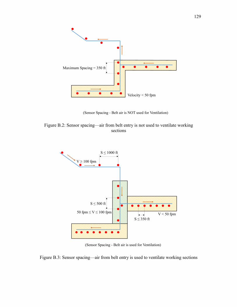
129
Figure B.2: Sensor spacing—air from belt entry is not used to ventilate working sections
Figure B.3: Sensor spacing—air from belt entry is used to ventilate working sections
Velocity < 50 fpm
Maximum Spacing = 350 ft
(Sensor Spacing - Belt air is NOT used for Ventilation)
V < 50 fpmS ≤ 350 ft
50 fpm ≤ V ≤ 100 fpm
S ≤ 500 ft
S ≤ 1000 ft
V ≥ 100 fpm
(Sensor Spacing - Belt air is used for Ventilation)

130
Figure B.4: Point-feed regulator and CO sensor locations
Point-feed regulator and CO sensor locationsLegend
Overcast
Stopping
Intake
Return Belt
CO sensor
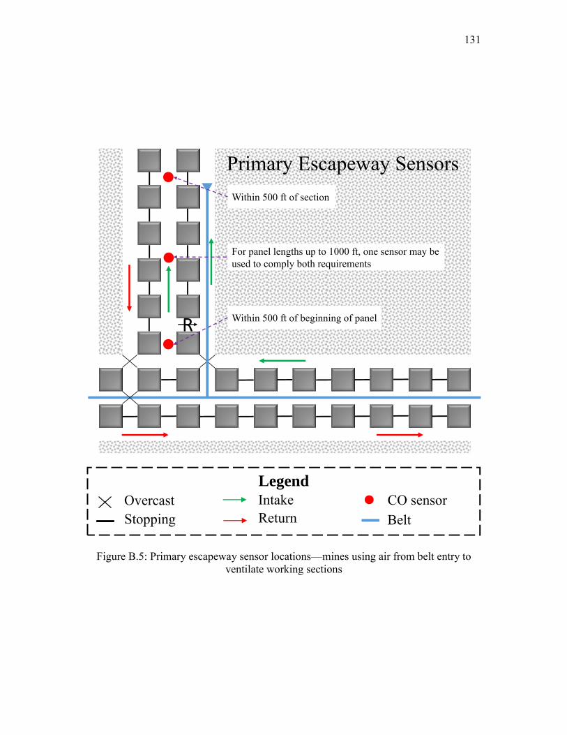
131
Figure B.5: Primary escapeway sensor locations—mines using air from belt entry to ventilate working sections
Primary Escapeway Sensors
R
Within 500 ft of section
For panel lengths up to 1000 ft, one sensor may be used to comply both requirements
Within 500 ft of beginning of panel
Legend
Overcast
Stopping
Intake
Return Belt
CO sensor

APPENDIX C
GUIDELINES FOR SPACING OF MONITORS

133
C.1 Spacing of Monitors
The most complicated part in the design of an AMS for a mine is to determine the
spacing of monitors. A guideline for spacing of monitors in underground mines is
presented step by step as a recommendation for an airway.
1. Determine the average entry height (H) and width (W).
2. Take the ratio of height to width (H/W) and, from Figure C.1, determine the
appropriate value for the entry parameter (ƳE).
3. Determine the type of sensor to be used (CO, CO2, or smoke) and its alarm
threshold (Xa); that is the gas concentration that will activate the sensor alarm.
4. Determine the primary combustible within the entry (either coal or wood) and, from
Table C.1, select the production constant (KX) for the gas to be detected.
5. Determine the average background level (Xo) of the gas to be detected.
6. Subtract Xo from Xa and divide the result by the appropriate KX-value.
7. From Figure C.2, determine the value of the gas parameter (ƳX) at the value of
(Xa − Xo)/KX defined in step 6.
8. Determine the average velocity (V), in feet per minute, within the entry and, in
Figure C.3, draw a vertical at this velocity parallel to the y-axis.
9. Multiply H by W to determine the average entry cross-sectional area (A) and, in
Figure C.3, draw a horizontal line at this A-value parallel to the x-axis.
10. Use the point of intersection of the vertical and horizontal lines in Figure C.3 to find
appropriate spacing equation for calculation of sensor spacing Z.
11. For intake and return airways, the resulting Z is recommended spacing. For belt
entry, the spacing also depends on velocity in airway as per the CFR 75.351. For V

134
≤ 50 fpm, if Z ≤ 350 ft, then use the value of Z else use 350 ft as appropriate
spacing. Similarly, for 50 < V ≤ 100 fpm; Z ≤ 500 ft; and for 100 < V ≤ 1000 fpm, Z
≤ 1000 ft. If the calculated sensor spacing (Z) is less than the sensor spacing value
in federal regulations, it is recommended to use the calculated spacing rather than
the sensor spacing mentioned in regulations.
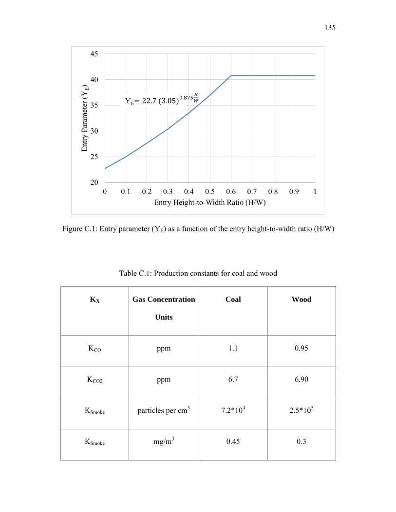
135
Figure C.1: Entry parameter (ƳE) as a function of the entry height-to-width ratio (H/W)
Table C.1: Production constants for coal and wood
KX Gas Concentration
Units
Coal Wood
KCO ppm 1.1 0.95
KCO2 ppm 6.7 6.90
KSmoke particles per cm3 7.2*104 2.5*105
KSmoke mg/m3 0.45 0.3
20
25
30
35
40
45
0 0.1 0.2 0.3 0.4 0.5 0.6 0.7 0.8 0.9 1
Entry
Par
amet
er (Ƴ
E)
Entry Height-to-Width Ratio (H/W)
ƳE= 22.7 (3.05)0.875𝐻
𝑊

136
Figure C.2: Gas parameter (ƳX) as a function of the ratio of alarm threshold to production constant (Xa − Xo)/KX
0
5
10
15
20
25
30
35
40
45
50
0 10 20 30 40 50 60 70 80 90 100
Gas
Par
amet
er (Ƴ
X)
(Xa-Xo)/KX
ƳX = 5Xa−Xo
KX
12
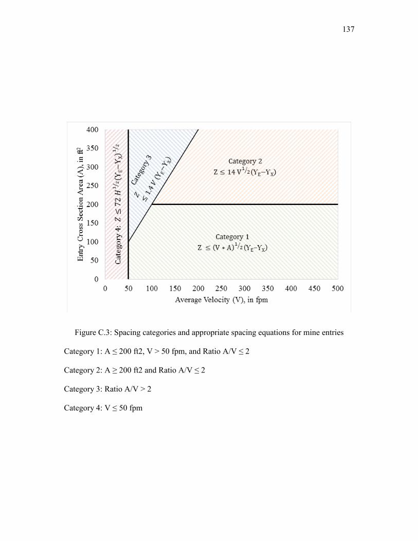
137
Figure C.3: Spacing categories and appropriate spacing equations for mine entries
Category 1: A ≤ 200 ft2, V > 50 fpm, and Ratio A/V ≤ 2
Category 2: A ≥ 200 ft2 and Ratio A/V ≤ 2
Category 3: Ratio A/V > 2
Category 4: V ≤ 50 fpm
REFERENCES
Benson, D. 2002. Use of booster fan ventilation at West Cliff colliery. Coal Operators'
Conference. University of Wollongong and the Australasian Institute of Mining and Metallurgy, Wollowgong, February 6–8.
Bian, B. 1989. The ultrasonic technique for monitoring air quantity of a mine fan. In
Proceedings of the 4th U.S. Mine Ventilation Symposium, Berkeley, CA, June 5–7. pp. 597–599.
Burton, R.C., Middleton, J.N., Wernick, B.J., Shereston, B.G., and Pretorisu, B.C.B.
1986. An automatic fire detection system for underground air recirculation schemes. International Symposium on Underground Mining, Nottingham, U.K., November 8–13.
Calizaya, F. 2000. Commissioning of a 750 kw centrifugal fan at PT Freeport
Indonesia’s deep ore zone mine. SME Preprint No. 00–132. Littleton, CO: SME. Calizaya, F. 2009. Guidelines for installing and operating booster fans in underground
mines. In Proceedings of the Ninth International Mine Ventilation Congress, New Delhi, India: Oxford and IBH.
Calizaya, F. and Tien, J.C. 2009. Utilization of belt air to ventilate working sections in
underground coal mines. Min. Eng. 61(4): 77–82. Calizaya, F., McPherson, M.J., and Mousset-Jones, P. 1989. Guidelines for
implementing a booster fan monitoring and control system in coal mines. In Proceedings of the 4th U.S. Mine Ventilation Symposium, Berkeley, CA. pp. 382–391.
Calizaya, F., McPherson, M.J., and Mousset-Jones, P. 1990. The Use of Booster Fans in
Underground Coal Mines. Final Report. Generic Mineral Technology Center in Mine Systems Designs, USBM. Grant No. G1125151. Berkeley, CA: University of California.

139
Calizaya, F., Nelson, M.G., and Shriwas, M. 2014. Risk assessment for the use of
booster fans in underground coal mines. Min. Eng. 66(3): 52–57
Chalmers, D.R. 2010. Inertization help or hindrance. In Proceedings of 13th US/North
American Mine Ventilation Symposium, Sudbury, ON, June 13–17. pp. 259–265
Chapanis, A. 1986. To err is human, to forgive, design. In Proceedings of the Annual
Professional Development Conference, New Orleans, LA, ASSE, 8 pp. Coal Mine Health and Safety Regulation, 2006.
www.legislation.nsw.gov.au/maintop/view/inforce/subordleg+783+2006+cd+0+N.
Accessed April 2014.
Conspec Controls, Inc. 2014. PLC atmospheric monitoring system network.
www.conspec–controls.com/products/atmospheric–monitoring–system.asp.
Accessed April 2014.
CRC Mining, 2014. Fibre optic sensing in underground coal mines.
www.crcmining.com.au/breakthrough–solutions/novel–fibre–optic–gas–sensing–in–
mining–project. Accessed April 2014.
Daly, B.B. 1992. Woods Practical Guide to Fan Engineering. Flakt Woods Limited.
http://www.venttech.co.nz/wp-content/uploads/2012/WPG_FE(s).pdf. Accessed
April 2014.
Edwards, J.C., Franks, R.A., Friel, G.F., and Yuan, L. 2006. CO dispersion from a coal
fire in a mine entry. In Proceedings of the 11th U.S./North American Mine
Ventilation Symposium, University Park, PA, June 5–7. London: Taylor and Francis
Group.
Eggins, B.R. 2002. Chemical Sensors and Biosensors. West Sussex, England: John
Wiley and Sons.
http://onlinelibrary.wiley.com/doi/10.1002/9780470511305.fmatter/pdf. Accessed
April 2014.
Federal Register. 2010. Title 30 CFR Part 75 Mandatory Safety Standards—
Underground Coal Mines, Subpart D—Ventilation. Code of Federal Regulations
July 1 edition.
www.msha.gov/30cfr/75.0.htm. Accessed April 2014.

140
Francart, W.J. 2005. 2003—MSHA survey—atmospheric monitoring systems in U.S.
underground coal mines. SME Preprint No. 00–132. Littleton, CO: SME
Grayson, R. L. 2001. Hazard identification, risk management, and hazard control. In
Mine Health and Safety Management. Edited by M. Karmis. Littleton, CO: SME
Griffin, K.R., Luxbacher, K.D., Schafrik, S.J., and Karmis, M.E. 2012. Comprehensive
ventilation simulation of atmospheric monitoring sensors in underground coal
mines. In Proceedings of 14th U.S. North American Mine Ventilation Symposium,
Salt Lake City, UT, June 17–20.
Hall, C.J. 1981. Mine Ventilation Engineering. American Institute of Mining,
Metallurgical and Petroleum Engineers, New York. ISBN: 9780895202734.
Hartman, H.L., Mutmansky, J.M., Ramani R.J., and Wang, Y.J. 1997. Mine Ventilation
and Air Conditioning. New York: John Wiley and Sons. ISBN: 0471116351.
Hemp, R. 1994. The effect of changes in barometric pressure on mines in the highveld
of South Africa. The Journal of the South African Institute of Mining and
Metallurgy. June 1994. pp. 133–146.
ISO 10816–3. 2014. Mechanical Vibration—Evaluation of Machine Vibration by
Measurements On Non–Rotating Parts. Geneva: International Organization for
Standardization. Available from www.iso.org.
Jorgensen, R. 1999. Howden Fan Engineering Handbook. Buffalo, NY: Howden
Buffalo, Inc.
http://av8rdas.wordpress.com/2012/02/28/howden-buffalos-fan-engineering-
handbook/. Accessed April 2014.
Kennedy, W. 1996. Practical Mine Ventilation. Chicago, IL: Intertec Publishing.
http://books.google.com/books/about/Practical_Mine_Ventilation.html?id=yZc8Ag
AACAAJ. Accessed April 2014.
Ketler, A.E. 2008. Atmospheric monitoring systems for very large mines. In
Proceedings of 12th U.S./North American Mine Ventilation Symposium, Reno, NV.
pp. 599–604.
Krog, R.B. 2002. Selection of underground booster fans. In Proceedings of 9th
U.S./North American Mine Ventilation Symposium, Kingston, ON, June 8–12.

141
Leeming, J.R., and Webb, D.J.T. 2012. Underground booster fans—current U.K.
practice for safe installation and management. In Proceedings of 14th U.S./North
American Mine Ventilation Symposium, Salt Lake City, UT, June 17–20.
Leeming, J.R., Hunneyball, S.R., Jobling, S., and Shead, P.R. 2008. The application af
nitrogen to control a spontaneous combustion event during a longwall face salvage.
In Proceedings of 12th U.S./North American Mine Ventilation Symposium, Reno,
NV, June 15–18.
Litton, C.D. 1979. Fire Detectors in Underground Mines. Information Circular IC–
8786. Washington, DC: U.S. Bureau of Mines.
Litton, C.D. 1983. Guidelines for Siting Product-of-Combustion Fire Sensors in
Underground Mines. Information Circular IC–8919. Washington, DC: U.S. Bureau
of Mines.
Martikainen, A.L, and Taylor, C.D. 2010. Breaking the ice on the booster fan dilemma
in U.S. underground coal mines. Min. Eng. 62(10): 47–53.
McPherson, M. 1993. Subsurface Ventilation Engineering. Clovis, CA: Mine
Ventilation Services.
http://www.mvsengineering.com/index.php/downloads/publications. Accessed April
2014.
McPherson, M.J., Dhar, N., and Mousset-Jones, P. 1985. A survey of booster fan use in
underground mines. In Proceedings of 3rd Annual Workshop, Generic Mineral
Technology Center on Mine Systems Design and Ground Control, November 25–26,
Lexington, KY.
Moreby, R. 2009. Ventilation—Australasian Coal Mining Practice. Carlton, Victoria:
Australasian Institute of Mining and Metallurgy.
MSHA (Mine Safety and Health Administration). 2007. Utilization of Belt Air and the
Composition and Fire Retardant Properties of Belt Materials in Underground Coal
Mining. Final Report. Washington, DC: MSHA.
MSHA (Mine Safety and Health Administration). 2013. Code of Federal Regulations:
Title 30. www.msha.gov/30cfr/download/30cfrdownload.asp. Accessed April 2014.

142
MSHA (Mine Safety and Health Administration). 2014. Atmospheric Monitoring
Systems Operator’s Training Guide. MSHA 3188. Washington, DC: MSHA.
www.msha.gov/beltair/AMSTrainingGuide.pdf. Accessed April 2014.
Mukopadhyay, A.K., Pathak, M.K., and Panigrahi, D.C. 1998. Study on vibration
problems in mine ventilation fans. Trans. SME 144:104–106.
Robinson, R., 1989. The use of booster fans and recirculation systems for
environmental control in British coal mines. In Proceedings of the 4th US Mine
Ventilation Symposium, Belkeley, CA, July 7–10.
Sandwell, G. 2012. Basic understanding of machinery vibration.
www.vibescorp.ca/pdf/basic_understanding_of_machinery_vibration.pdf. Accessed
April 2014.
Smallwood, M.L., Horn, M., and Meade, K. 1993. Programmable logic controller based
mine wide monitoring system. In Proceedings of the 6th Us Mine Ventilation
Symposium. Salt Lake City, UT, June 21–23. pp. 495–500.
Smutny, L., and Farana, R. 2003. Mining smart instrumentation on future intelligent
mines. Mine Planning and Equipment Selection. Kalgoorlie, WA, April 23– 25.
ISBN: 978-1-875776-96-2.
Snaith, J.K. 1998. DOM Fan Commissioning. Site Report 348, Contract Ref. CS 3254,
Howden Sirocco PTY, Limited, 97–103 Pacific Highway, North Sydney, NSW
2060, Australia.
Stephens, M. 2011. Laboratory and numerical modeling used to characterize leakage in
underground coal mines. M.S. Thesis, University of Utah, Salt Lake City, UT.
Stricklin, K.G. 2013. Automatic fire sensor and warning device systems using carbon
monoxide sensors and atmospheric monitoring system inspection procedure.
Handbook Number: PH–13–V–3. Washington, DC: Mine Safety and Health
Administration. pp. 13–25.
United Kingdom Statutory Instruments. 1956. No. 1764, Mines and Quarries (5) Ventilation, The Coal and Other Mines (Ventilation) Order. www.legislation.gov.uk/uksi/1956/1764/made. Accessed April 2014.

143
Valoski, M. P. 2010. Instruments for gas analysis at mine fires/explosions. SME Preprint No. 10–039. Littleton, CO: SME.