monster r istr - 731 / 00 96480921a kit silenziatori ... · documentazione necessaria per eseguire...
TRANSCRIPT

Symbols
To allow quick and easy consultation, this manual uses graphic symbols to highlight situations in which maximum care is required, as well as practical advice or information.Pay attention to the meaning of the symbols since they serve to avoid repeating technical concepts or safety warnings throughout the text. The symbols should therefore be seen as real reminders. Please refer to this page whenever in doubt as to their meaning.
WarningFailure to follow these instructions might give raise to a dangerous situation and provoke severe personal injuries or even death.
CautionFailure to follow these instructions might cause damages to the vehicle and/or its components.
NotesUseful information on the procedure being described.
References
Parts highlighted in grey and with a numeric reference (Example 1 ) are the accessory to be installed and any assembly components supplied with the kit.
Parts with an alphabetic reference (Example A ) are the original components fitted on the vehicle.
Any right- or left-hand indication refers to the vehicle direction of travel.
General notes
WarningCarefully perform the operations on the following pages since they might negatively affect rider safety.
WarningCarefully perform the operations on the following pages since they might negatively affect rider safety.
NotesThe following documents are necessary for assembling the Kit:WORKSHOP MANUAL of your bike model.
NotesShould it be necessary to change any kit parts, please refer to the attached spare part table.
Simbologia
Per una lettura rapida e razionale sono stati impiegati simboli che evidenziano situazioni di massima attenzione, consigli pratici o semplici informazioni.Prestare molta attenzione al significato dei simboli, in quanto la loro funzione è quella di non dovere ripetere concetti tecnici o avvertenze di sicurezza. Sono da considerare, quindi, dei veri e propri “promemoria”.Consultare questa pagina ogni volta che sorgeranno dubbi sul loro significato.
AttenzioneLa non osservanza delle istruzioni riportate può creare una situazione di pericolo e causare gravi lesioni personali e anche la morte.
ImportanteIndica la possibilità di arrecare danno al veicolo e/o ai suoi componenti se le istruzioni riportate non vengono eseguite.
NoteFornisce utili informazioni sull’operazione in corso.
Riferimenti
I particolari evidenziati in grigio e riferimento numerico (Es. 1 ) rappresentano l’accessorio da installare e gli eventuali componenti di montaggio forniti a kit.
I particolari con riferimento alfabetico (Es. A ) rappresentano i componenti originali presenti sul motoveicolo.
Tutte le indicazioni destro o sinistro si riferiscono al senso di marcia del motociclo.
Avvertenze generali
AttenzioneLe operazioni riportate nelle pagine seguenti devono essere eseguite da un tecnico specializzato o da un’officina autorizzata DUCATI.
AttenzioneLe operazioni riportate nelle pagine seguenti se non eseguite a regola d’arte possono pregiudicare la sicurezza del pilota.
NoteDocumentazione necessaria per eseguire il montaggio del Kit è il MANUALE OFFICINA, relativo al modello di moto in vostro possesso.
NoteNel caso fosse necessaria la sostituzione di un componente del kit consultare la tavola ricambi allegata.
Kit silenziatori racingRacing silencer kit
1
Monster R ISTR - 731 / 00 96480921A

WarningThis exhaust kit is for racing use (i.e., closedcourse competition) only. After mounting this exhaust kit, the vehicle cannot be used on public roads. Owner is responsible for compliance with all laws concerning racing use and competition vehicles.
AttenzioneIl presente kit di scarico è per utilizzo esclusivo su pista (esempio: gare sportive su circuiti).Dopo il montaggio del kit, il motoveicolo non può circolare su strade pubbliche. Il proprietario si impegna ad attenersi alle leggi e regolamenti vigenti sull’utilizzo in pista e sui motoveicoli da competizione.
Pos. Denominazione Description
1 Silenziatore superiore Upper silencer
2 Silenziatore inferiore Lower silencer
3 Staffa supporto silenziatore Silencer support bracket
4 Vite TEF M6x16 TEF screw M6x16
5 DDS map key dp1 1305 DDS map key dp1 1305
6 Raccordo a Y Y-shaped union
7 Paracalore silenziatore Silencer heat guard
8 Distanziale Spacer
9 Vite TBEI M5x14 TBEI screw M5x14
10 Clip Clip
11 Rosetta aramidica Aramid washer
12 Molla scarichi Exhaust spring
2 ISTR 731 / 00
4
4
11
3 9
8 10
11
9
711
8
9
11
8
10
4
12
1
2
5
12 6

Removing the original components
WarningThe engine and exhaust parts become hot when the motorcycle engine is running and will stay hot for some time after the engine has been stopped.Wear heat-resistant gloves before handling these components or allow the engine and exhaust system to cool down before proceeding.
WarningThe exhaust system might be hot, even after engine is switched OFF; pay particular attention not to touch exhaust system with any body part and do not park the motorcycle next to inflammable material (wood, leaves etc.).
Removing the silencer
Loosen clamp (B).Loosen screw (A1) while holding nut (A5) on the opposite side.Make sure the 2 vibration dampers (A3) and bushing (A2) remain fitted on the RH footpeg holder plate (C).Remove silencer (A).Collect washer (A4), screw (A1) and nut (A5).
Smontaggio componenti originali
AttenzioneIl motore e le parti del sistema di scarico diventano molto calde con l'uso della motocicletta, e rimangono calde ancora per lungo tempo dopo aver fatto funzionare il motore. Per manipolare queste parti usare dei guanti anticalore, o attendere che si siano ben raffreddate.
AttenzioneL'impianto di scarico può essere caldo, anche dopo lo spegnimento del motore; prestare molta attenzione a non toccare con nessuna parte del corpo l'impianto di scarico e a non parcheggiare il veicolo in prossimità di materiali infiammabili (compreso legno, foglie, ecc.).
Smontaggio silenziatore
Allentare la fascetta (B).Svitare la vite (A1) mantenendo, dal lato opposto, il dado (A5).Assicurarsi che i n.2 gommini antivibranti (A3) e la boccola (A2) rimangano montati sulla piastra portapedana destra (C).Rimuovere il silenziatore (A).Recuperare la rondella (A4), la vite (A1) e il dado (A5).
3ISTR 731 / 00
A3
A1A
B
A2
A3
A4
A5
C
4 ISTR 731 / 00
1
3
12
7
8 11
8
11
10
9
11911
11
8
10
9
4
4
4
2
12
6
A4
3A A5
A3
A3A2
A1
B D
10 Nm ± 10%
10 Nm ± 10%
10 Nm ± 10%
4 Nm ± 10%
4 Nm ± 10%
4 Nm ± 10%
3
4
4
9
11
11
7
8
12
8A
X
Z
Y
18 Nm ± 10%
7 Nm ± 10%
C

Kit installation
CautionCheck that all components are clean and in perfect condition before installation.Adopt any precaution necessary to avoid damages to any part of the motorcycle you are working on.
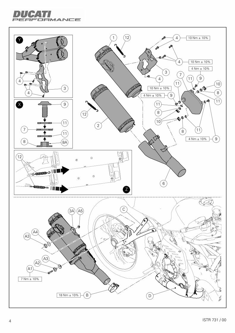
Insert the upper (1) and lower (2) silencer in the manifold (6). Fix the upper (1) and lower (2) silencer to the manifold (6) fitting no. 2 springs (12) with a spring stretcher available on the market, as shown in figure (Z).Fit bracket (3) on silencers (1) and (2) starting the 6 screws (4). as shown in figure (Y).Tighten the 6 screws (4) to the specified torque.Fit no. 3 quick fasteners (10) on manifold (6) brackets.
Fit no. 3 aramid washers (11) on no. 3 screws (9).Fit no. 3 screws (9) in heat guard holes (7) on the indicated side.Fit the other 3 aramid washers (11) and no.3 spacers with collar (8) on screw (9) projecting parts.
NotesThe 3 spacers (8) must be positioned with collar (8A) facing the heat guard, as shown on figure (X).
Position the just pre-assembled silencer heat guard assembly onto manifold (6) and drive it fully home by hand, making sure that aramid washers (11) are fully seated so as to prevent them from being damaged during tightening.Tighten the 3 screws (8) to the specified torque.
Insert original clamp (B) onto central body (D).Insert the already preassembled silencer unit into the central body (D).Make sure the 2 vibration dampers (A3) and bushing (A2) are fitted on the RH footpeg holder plate (C).Start original screw (A1) on bushing (A2) after placing washer (A4) between the internal vibration damper (A3) and the silencer bracket (3A).Tighten original nut (A5) on screw projection (A1) on the opposite side.Tighten screw (A1) to the specified torque, while locking nut (A5) on the opposite side.Position and tighten the original clamp (B) to the specified torque.
Montaggio componenti kit
ImportanteVerificare, prima del montaggio, che tutti i componenti risultino puliti e in perfetto stato.Adottare tutte le precauzioni necessarie per evitare di danneggiare qualsiasi parte nella quale ci si trova adoperare.
Inserire il silenziatore superiore (1) e inferiore (2) nel collettore (6). Fissare il silenziatore superiore (1) e inferiore (2) al collettore (6) montando n.2 molle (12) con un tiramolle commerciale, come indicato in figura (Z).Montare la staffa (3) sui silenziatori (1) e (2) impuntando le n. 6 viti (4), come indicato in figura (Y).Serrare le n.6 viti (4) alla coppia indicata.Montare i n.3 fissaggi rapidi (10) sulle staffe del collettore (6).
Inserire le n.3 rosette aramidiche (11) su n.3 viti (9).Introdurre le n.3 viti (9) nei fori del paracalore (7), dal lato indicato.Inserire altre 3 rosette aramidiche (11) e n.3 distanziali con collare (8) sulle sporgenze delle viti (9).
NoteI n.3 distanziali (8) devono essere orientati con il collare (8A) rivolto verso il paracalore, come indicato in figura (X).
Posizionare il gruppo paracalore silenziatore appena premontato sul collettore (6), avvitare a mano fino a battuta e assicurarsi che le rosette aramidiche (11) siano nelle rispettive sedi perfettamente a battuta al fine di evitare che si danneggino in fase di serraggio.Serrare le n.3 viti (9) alla coppia indicata.
Inserire la fascetta originale (B) sul corpo centrale (D).Inserire il gruppo silenziatori, premontato in precedenza, nel corpo centrale (D).Assicurandosi che i n.2 gommini antivibranti (A3) e la boccola (A2) siano montati sulla piastra portapedana destra (C).Impuntare la vite originale (A1) sulla boccola (A2), interponendo tra il gommino antivibrante interno (A3) e la staffa silenziatore (3A) la rondella (A4).Avvitare dal lato opposto, sulla sporgenza della vite (A1), il dado originale (A5).Serrare la vite (A1) alla coppia indicata, mantenendo dalla parte opposta, il dado (A5).Orientare e serrare la fascetta originale (B) alla coppia indicata.
5 ISTR 731 / 00

6 ISTR 731 / 00
1A 1
1B
2A
2
2B
F
F1
1
2

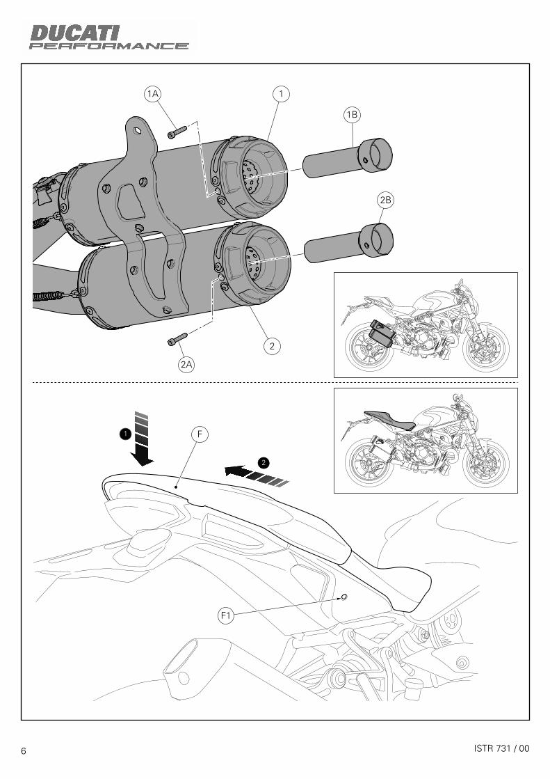
NotesAccording to regulations currently in force, it is possible to remove the dB killer in facilities used as race tracks.
Loosen the screw (1A) and slide dB killer (1B) from the upper silencer (1) using a suitable hook.Loosen the screw (2A) and slide dB killer (2B) from the lower silencer (2) using a suitable hook.
Engine control unit calibration
NotesThe Racing silencer kit is supplied with MAP-KEY, which enables engine control unit "Performance" calibration download.
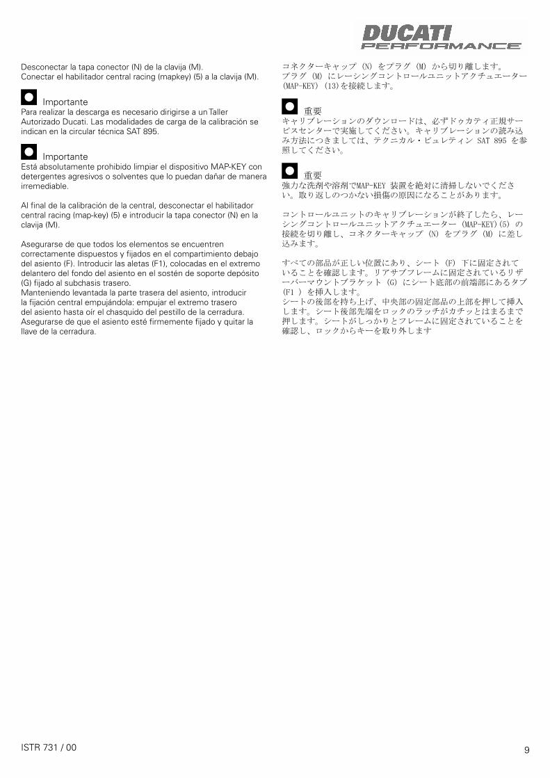
Insert the key in lock (F1), turn clockwise while pressing down at the latch to help release the pin.Remove the seat (F) pulling it backwards until sliding it out of the front retainers.
NoteÈ possibile rimuovere il riduttore fonico, in base alle regole vigenti, nelle strutture adibite a pista.
Svitare la vite (1A) e sfilare con un gancio appropriato il riduttore fonico (1B) dal silenziatore superiore (1).Svitare la vite (2A) e sfilare con un gancio appropriato il riduttore fonico (2B) dal silenziatore inferiore (2).
Calibrazione centralina controllo motore
NoteIl kit silenziatori Racing viene fornito con MAP-KEY che consente il download della calibrazione centralina controllo motore “Performance”.
Introdurre la chiave nella serratura (F1), ruotarla in senso orario e contemporaneamente premere verso il basso in prossimità del chiavistello per agevolare lo sgancio del piolo. Sfilare la sella (F) dai fermi anteriori tirandola all’indietro.
7 ISTR 731 / 00

8 ISTR 731 / 00
M
N5
F1
G
F

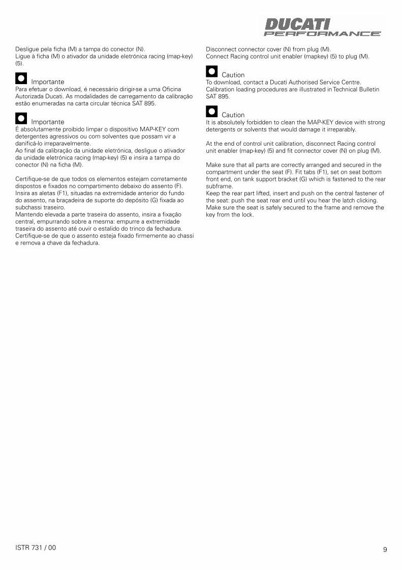
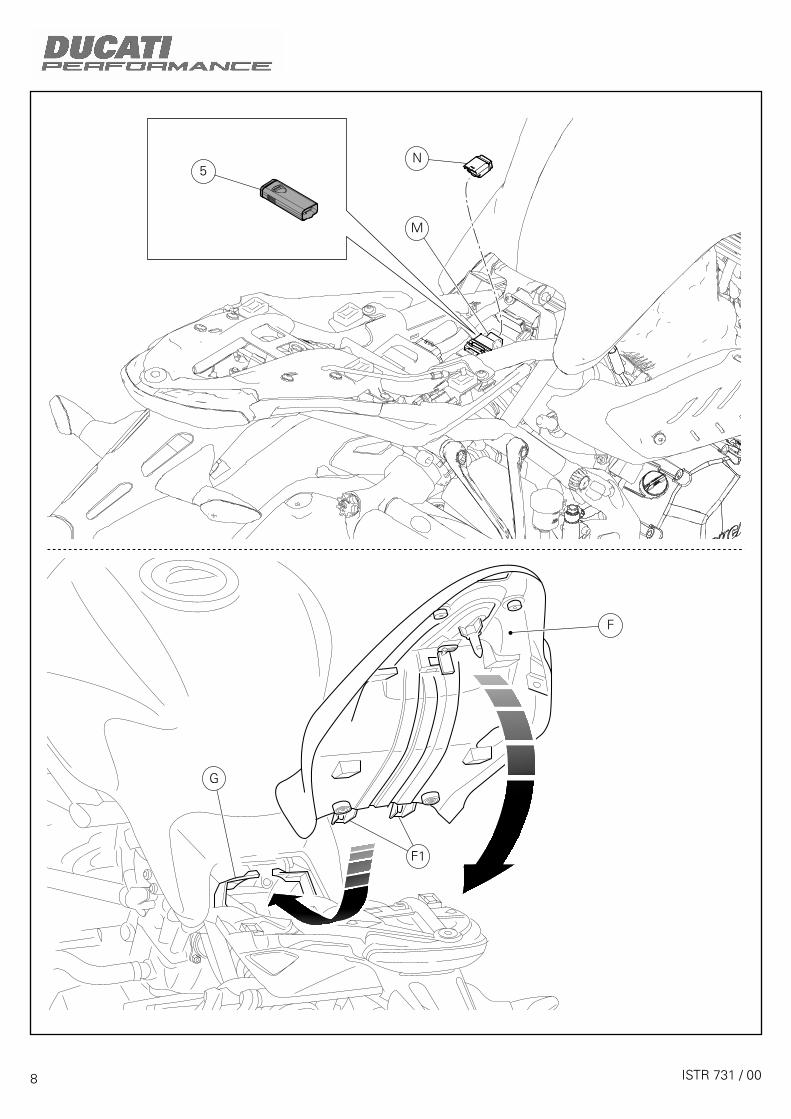
Disconnect connector cover (N) from plug (M).Connect Racing control unit enabler (mapkey) (5) to plug (M).
CautionTo download, contact a Ducati Authorised Service Centre. Calibration loading procedures are illustrated in Technical Bulletin SAT 895.
CautionIt is absolutely forbidden to clean the MAP-KEY device with strong detergents or solvents that would damage it irreparably.
At the end of control unit calibration, disconnect Racing control unit enabler (map-key) (5) and fit connector cover (N) on plug (M).
Make sure that all parts are correctly arranged and secured in the compartment under the seat (F). Fit tabs (F1), set on seat bottom front end, on tank support bracket (G) which is fastened to the rear subframe.Keep the rear part lifted, insert and push on the central fastener of the seat: push the seat rear end until you hear the latch clicking. Make sure the seat is safely secured to the frame and remove the key from the lock.
Scollegare dalla spina (M) il coperchio connettore (N). Collegare alla spina (M) l'abilitatore centralina racing (map-key) (5).
ImportantePer effettuare il download è necessario rivolgersi ad un’Officina Autorizzata Ducati. Le modalità di caricamento calibrazione sono elencate sulla circolare tecnica SAT 895.
ImportanteÈ assolutamente vietato pulire il dispositivo MAP-KEY con detergenti aggressivi o solventi che lo danneggerebbero irrimediabilmente.
Al termine della calibrazione centralina, scollegare l'abilitatore centralina racing (map-key) (5) e inserire il coperchio connettore (N) nella spina (M).
Assicurarsi che tutti gli elementi siano correttamente disposti e fissati nel vano sotto la sella (F). Inserire le alette (F1), poste sull'estremità anteriore del fondo sella, nella staffa supporto serbatoio (G) fissata al telaietto posteriore.Tenendo sollevata la parte posteriore della sella, inserire il fissaggio centrale, spingendo sopra di esso: spingere sull’estremità posteriore della sella fino ad udire lo scatto del chiavistello della serratura.Assicurarsi che la sella sia saldamente fissata al telaio e rimuovere la chiave dalla serratura.
9 ISTR 731 / 00
NOTE / NOTES
1 P/N 商品名
2 P/N 商品名
3 P/N 商品名
4 P/N 商品名
5 P/N 商品名
ご注文商品
レース専用部品 ご注文書DUCATI PERFORMANCE accessories
モデル名
ご注文日
販売日 年 月 日
1. 上記ご記入の上、弊社アフターセールス部までFAXしてください。FAX:03-6692-1317
お客様ご記入欄
私は上記レース専用部品を下記車両に装着し、サーキット走行のみに利用し、一般公道には利用しません。
販売店署名
販売店様へお願い
車台番号 ZDM
お客様署名
ドゥカティ正規ネットワーク店記入欄
お客様に上記レース専用部品を販売し、レース専用部品のご利用方法を説明いたしました。
1. 上記ご記入の上、弊社アフターセールス部までFAXしてください。FAX:03-6692-13172. 取り付け車両1台に1枚でご使用ください。
ISTR 731 / 00

Symbole
Zum schnellen und übersichtlichen Lesen werden Symbole verwendet, die außerordentlich wichtige Situationen, praktische Ratschläge oder auch nur einfache Informationen hervorheben. Der Bedeutung dieser Symbole ist besondere Aufmerksamkeit zu schenken, da sich hierdurch das ständige Wiederholen von technischen Konzepten oder Sicherheitshinweisen erübrigt. Sie stellen daher regelrechte „Merker“ dar. Diese Seite ist immer dann zur Hand zu nehmen, wenn Zweifel über die Bedeutung eines Symbols bestehen sollten.
AchtungEine Nichtbeachtung der hier wiedergegebenen Anweisungen kann Gefahrensituationen schaffen und zu schweren Verletzungen und auch zum Tod führen.
WichtigWeist darauf hin, dass bei Nichteinhaltung der hier wiedergegebenen Anweisungen die Möglichkeit für Schäden am Fahrzeug und/oder seiner Komponenten besteht.
HinweisÜbermittelt nützliche Informationen zum betreffenden Arbeitseingriff.
Bezugsangaben
Die grau gekennzeichneten Bestandteile mit numerischem Bezug (Bsp. 1 ) geben das zu installierende Bestandteil und die eventuellen, im Kit enthaltenen Montagekomponenten wieder.
Die Bestandteile mit alphabetischem Bezug (Bsp. A ) geben die Original-Bestandteile wieder, die am Motorrad verbaut wurden.
Alle Angaben wie „rechts” oder „links” beziehen sich auf die Fahrtrichtung des Motorrads.
Allgemeine Warnhinweise
AchtungWerden die auf den folgenden Seiten beschriebenen Arbeitsmaßnahmen nicht fachgerecht ausgeführt, kann sich dies auf die Sicherheit des Fahrers auswirken.
AchtungWerden die auf den folgenden Seiten beschriebenen Arbeitsmaßnahmen nicht fachgerecht ausgeführt, kann sich dies auf die Sicherheit des Fahrers auswirken.
HinweisFür die Montage des Kits sind folgende Unterlagen erforderlich: WERKSTATTHANDBUCH, des sich in Ihrem Besitz befindlichen Motorrads.
HinweisSollte sich der Austausch eines Bestandteils des Kits als erforderlich erweisen, ist dazu Bezug auf die beiliegende Ersatzteiltafel zu nehmen.
Symboles
Pour faciliter la consultation de ce manuel, des symboles signalent des situations exigeant le maximum d'attention, des conseils pratiques ou de simples informations. Lire attentivement la signification de ces symboles car ils renvoient à des concepts techniques ou des consignes de sécurité de la plus grande importance. Ils doivent être considérés comme de véritables « aide-mémoire ». Toujours consulter cette page en cas de doute concernant leur signification.
AttentionLa non-observance des instructions reportées ci-dessous peut créer une situation dangereuse et provoquer de graves lésions personnelles voire la mort.
ImportantIndique la possibilité d'endommager le véhicule et/ou ses composants si les instructions reportées ci-dessous ne sont pas suivies.
RemarquesFournit des informations utiles sur l'opération en cours.
Références
Les pièces surlignées en gris et la référence numérique (Ex. 1 ) représentent l'accessoire à installer et les composants de montage éventuels fournis en kit.
Les pièces avec référence alphabétique (Ex. A ) représentent les composants d'origine présents sur le motocycle.
Toutes les indications droite ou gauche se réfèrent au sens de marche la moto.
Avertissements généraux
AttentionLes opérations indiquées dans les pages suivantes, au cas où elles ne seraient pas effectuées selon les règles de l'art pourraient compromettre la sécurité du pilote.
AttentionLes opérations indiquées dans les pages suivantes, au cas où elles ne seraient pas effectuées selon les règles de l'art pourraient compromettre la sécurité du pilote.
RemarquesLa documentation nécessaire pour effectuer la pose du Kit est le : MANUEL D'ATELIER, relatif au modèle de moto en votre possession.
RemarquesAu cas où il serait nécessaire d'effectuer le remplacement d'un composant du kit, il faudra consulter la planche relative aux pièces détachées ci-jointe.
Kit silencieux racingKit Racing-Schalldämpfer
1
Monster R ISTR - 731 / 00 96480921A

AchtungVorliegendes Auspuffkit ist ausschließlich für den Einsatz auf der Rennstrecke (zum Beispiel bei Sportveranstaltungen) vorgesehen. Nach der Montage des Auspuffkits darf das Motorrad nicht mehr auf öffentlichen Straßen gefahren werden.Der Eigentümer verpflichtet sich, die für den Einsatz auf Rennstrecken und für Rennmotorräder geltenden Gesetze und Verordnungen zu beachten.
AttentionLe présent kit d’échappement est destiné à l’usage exclusif sur piste (exemple : compétitions sportives sur circuits).Après l’installation du kit, le motocycle ne peut pas circuler sur des voies publiques.Le propriétaire s’engage formellement à se conformer aux lois et règlements sur l’usage des motocycles sur piste et sur les motocycles de compétition.
Pos. Designation Bezeichnung
1 Silencieux supérieur Oberer Schalldämpfer
2 Silencieux inférieur Unterer Schalldämpfer
3 Bride de support silencieux Schalldämpferhaltebügel
4 Vis THB M6x16 Geflanschte Sechskantschraube M6x16
5 DDS map key dp1 1305 DDS Map Key dp1 1305
6 Raccord en Y Y-Anschluss
7 Pare-chaleur silencieux Schalldämpferwärmeschutz
8 Entretoise Distanzstück
9 Vis TBHC M5x14 Linseninnensechskantschraube M5x14
10 Clip Clip
11 Rondelle aramidique Aramid-Unterlegscheibe
12 Ressort du système d'échappement Auspufffeder
2 ISTR 731 / 00
4
4
11
3 9
8 10
11
9
711
8
9
11
8
10
4
12
1
2
5
12 6

Ausbau der Original-Bestandteile
AchtungDer Motor und die Auspuffanlage werden während der Fahrt sehr heiß und behalten diese Temperaturen auch nach Abstellen des Motors über lange Zeit hinweg bei.Für die Handhabung dieser Teile sind daher Wärmeschutzhandschuhe zu tragen bzw. ist so lange zu warten, bis sie abgekühlt sind.
AchtungDie Auspuffanlage kann auch nach dem Ausschalten des Motors noch heiß sein, daher ist darauf zu achten, dass man mit keinem Körperteil mit der Auspuffanlage in Berührung kommt und dass das Fahrzeug nicht in der Nähe von entflammbarem Material (einschließlich Holz, Blätter usw.) abgestellt wird.
Abnahme des Schalldämpfers
Die Schelle (B) lockern.Die Schraube (A1) lösen und dabei an der gegenüberliegenden Seite die Mutter (A5) kontern.Sicherstellen, dass die 2 Schwingungsdämpfergummis (A3) und die Buchse (A2) an der rechten Fußrastenhalterplatte (C) montiert bleiben.Den Schalldämpfer (A) entfernen.Die Unterlegscheibe (A4), die Schraube (A1) und die Mutter (A5) aufnehmen.
Dépose composants d'origine
AttentionLe moteur et le système d'échappement atteignent des températures très élevées pendant l'utilisation de la moto et restent chauds longtemps après l'arrêt du moteur. Pour manipuler ces pièces, porter des gants isolants ou attendre qu'elles se refroidissent.
AttentionLe système d'échappement peut être chaud, même après avoir arrêté le moteur : prendre garde qu'aucune partie du corps ne touche le système d'échappement et veiller à ne pas garer le motocycle à proximité de matières inflammables (y compris le bois, les feuilles, etc.).
Dépose du silencieux
Desserrer le collier serre-flex (B).Desserrer la vis (A1) en tenant, du côté opposé, l'écrou (A5).S'assurer que les 2 plots antivibratoires (A3) et la bague (A2) restent installés sur la platine de support repose-pied droite (C).Déposer le silencieux (A).Récupérer la rondelle (A4), la vis (A1) et l'écrou (A5).
3ISTR 731 / 00
A3
A1A
B
A2
A3
A4
A5
C

4 ISTR 731 / 00
1
3
12
7
8 11
8
11
10
9
11911
11
8
10
9
4
4
4
2
12
6
A4
3A A5
A3
A3A2
A1
B D
10 Nm ± 10%
10 Nm ± 10%
10 Nm ± 10%
4 Nm ± 10%
4 Nm ± 10%
4 Nm ± 10%
3
4
4
9
11
11
7
8
12
8A
X
Z
Y
18 Nm ± 10%
7 Nm ± 10%
C

Montage der Komponenten des Kits
WichtigVor der Montage überprüfen, dass sich alle Komponenten im sauberen und perfekten Zustand befinden.Alle erforderlichen Vorsichtsmaßnahmen treffen, um eine Beschädigung der Oberflächen der Komponenten, die vom Eingriff betroffen sind, zu vermeiden.
Den oberen (1) und den unteren (2) Schalldämpfer in den Auspuffkrümmer (6) einfügen. Den oberen (1) und den unteren (2) Schalldämpfer am Auspuffkrümmer (6) befestigen, dazu, wie in Abbildung (Z) dargestellt, mit einem handelsüblichen Federzieher 2 Federn (12) montieren.Den Bügel (3) an den Schalldämpfern (1) und (2) durch Ansetzen der 6 Schrauben (4), wie auf der Abbildung (Y) angegeben, montieren.Die 6 Schrauben (4) mit dem angegebenen Anzugsmoment anziehen.Die 3 Schnellbefestigungen (10) an den Bügeln des Auspuffkrümmers (6) montieren.
Die 3 Aramid-Unterlegscheiben (11) auf die 3 Schrauben (9) fügen.Die 3 Schrauben (9) von der angegebenen Seite aus in die Bohrungen des Wärmeschutzes (7) einfügen.Die weiteren 3 Aramid-Unterlegscheiben (11) sowie die 3 Distanzstücke mit Bund (8) auf die überstehenden Schraubenenden (9) fügen.
HinweisDie 3 Distanzstücke (8) müssen dabei mit dem Bund (8A) zum Wärmeschutz gerichtet sein; siehe dazu Abbildung (X).
Die soeben vormontierte Wärmeschutzeinheit des Schalldämpfers am Auspuffkrümmer (6) anordnen und von Hand bis auf Anschlag einschrauben, dabei sicherstellen, dass die Aramid-Unterlegscheiben (11) jeweils perfekt in ihren Sitzen auf Anschlag liegen, damit sie in der Anzugphase nicht beschädigt werden.Die 3 Schrauben (9) mit dem angegebenen Anzugsmoment anziehen.
Die Original-Schelle (B) auf den mittleren Körper (D) fügen.Die vormontierte Schalldämpfereinheit in den mittleren Körper (D) einfügen.Sicherstellen, dass die 2 Schwingungsdämpfergummis (A3) und die Buchse (A2) an der rechten Fußrastenhalterplatte (C) montiert sind.Die Original-Schraube (A1) auf der Buchse (A2) ansetzen und die Unterlegscheibe (A4) zwischen dem inneren Schwingungsdämpfergummi (A3) und dem Schalldämpferbügel (3A) einfügen.An der gegenüberliegenden Seite die Original-Mutter (A5) auf den Vorsprung der Schraube (A1) schrauben.Die Schraube (A1) mit dem angegebenen Anzugsmoment anziehen und dabei an der gegenüberliegenden Seite die Mutter (A5) kontern.Die Original-Schelle (A) ausrichten und mit dem angegebenen Anzugsmoment anziehen.
Pose composants kit
ImportantVérifier, avant la pose, que tous les composants sont propres et en parfait état.Adopter toutes les précautions nécessaires pour éviter d'endommager la surface externe des composants où on opère.
Introduire les silencieux supérieur (1) et inférieur (2) dans le collecteur (6). Fixer les silencieux supérieur (1) et inférieur (2) au collecteur (6) en montant les deux ressorts (12) à l'aide d'un monte-ressort disponible dans le commerce, comme la figure (Z) le montre.oser la bride (3) sur les silencieux (1) et (2) en présentant les 6 vis (4), comme la figure (Y) le montre.Serrer les 6 vis (4) au couple indiqué.Poser les 3 raccords rapides (10) sur les brides du collecteur (6).
Insérer les 3 rondelles aramidiques (11) sur les 3 vis (9).Insérer les 3 vis (9) dans les trous du pare-chaleur (7), du côté indiqué.Insérer 3 autres rondelles aramidiques (11) et 3 entretoises à collerette (8) sur les saillies des vis (9).
RemarquesLes 3 entretoises (8) doivent être orientées avec la collerette (8A) tournée vers le pare-chaleur, comme la figure (X) le montre.
Positionner l'ensemble pare-chaleur silencieux qui vient d'être pré-monté sur le collecteur (6), visser à la main jusqu'en butée et s'assurer que les rondelles aramidiques (11) sont dans les logements correspondants parfaitement en butée pour éviter qu'elles puissent s'abîmer pendant la phase de serrage.Serrer les 3 vis (9) au couple indiqué.
Insérer le collier serre-flex d'origine (B) sur le corps central (D).Insérer l'ensemble silencieux,préalablement installé, dans le corps central (D).S'assurer que les 2 plots antivibratoires (A3) et la bague (A2) sont installés sur la platine de support repose-pied droite (C).Présenter la vis d'origine (A1) sur la bague (A2), en interposant la rondelle (A4) entre le plot antivibratoire interne (A3) et la bride du silencieux (3A).Visser l'écrou d'origine (A5) sur la saillie de la vis (A1) du côté opposé.Serrer la vis (A1) au couple prescrit en tenant l'écrou (A5) du côté opposé.Orienter et serrer le collier serre-flex d'origine (A) au couple indiqué.
5 ISTR 731 / 00

6 ISTR 731 / 00
1A 1
1B
2A
2
2B
F
F1
1
2

HinweisDer dB-Killer kann den in den sich in Kraft befindlichen Reglements gemäß im Rennstreckeneinsatz abgenommen werden.
Die Schraube (1A) lösen und unter Anwendung eines angemessenen Hakens den Schalldämpfereinsatz (1B) aus dem oberen Schalldämpfer (1) herausziehen.Die Schraube (2A) lösen und unter Anwendung eines angemessenen Hakens den Schalldämpfereinsatz (2B) aus dem unteren Schalldämpfer (2) herausziehen.
Kalibrierung des Motorsteuergeräts
HinweisDas Kit Racing-Schalldämpfer wird mit dem MAP-KEY geliefert, der das Download der „Performance”-Kalibrierung des Motorsteuergeräts ermöglicht.
Den Schlüssel in das Schloss (F1) stecken, im Uhrzeigersinn drehen und gleichzeitig am Schlossriegel nach unten drücken, um das Entriegeln des Stifts zu erleichtern. Die Sitzbank (F) nach hinten ziehen und so von den vorderen Klemmhalterungen abziehen.
RemarquesIl est possible de déposer le réducteur cranté selon les règles envigueur, dans les structures transformées en pistes.
Desserrer la vis (1A) et sortir le réducteur de bruit (1B) du silencieux supérieur (1) à l'aide d'un crochet approprié.Desserrer la vis (2A) et sortir le réducteur de bruit (2B) du silencieux inférieur (2) à l'aide d'un crochet approprié.
Calibrage centrale commande moteur
RemarquesLe kit silencieux Racing est fourni avec MAP-KEY qui permet de télécharger le réglage de la centrale commande moteur « Performance ».
Introduire la clé dans la serrure (F1), la tourner dans le sens des aiguilles d'une montre en poussant vers le bas à proximité du verrou pour faciliter le décrochage de la vis sans tête. Dégager la selle (F) de ses arrêtoirs avant et la tirer vers l'arrière.
7 ISTR 731 / 00

8 ISTR 731 / 00
M
N5
F1
G
F

Die Abdeckung des Verbinders (N) vom Stecker (M) lösen.Den Stick des Racing-Mappings (Map-Key) (5) an den Stecker (M) schließen.
WichtigFür das Durchführen des Downloads muss man sich an eine Ducati Vertragswerkstatt wenden. Für das Einlesen der Kalibrierung ist das im Technischen Rundschreiben SAT 895 beschriebene Verfahren zu befolgen.
WichtigEs ist strikt verboten, die MAP-KEYVorrichtung mit aggressiven Reinigungsmittel oder Lösungsmitteln zu reinigen, da diese dabei in irreparabler Weise beschädigt werden würde.
Nach der Kalibrierung des Steuergeräts, den Stick des Racing-Mappings (Map-Key) (5) abziehen und die Steckerkappe (N) auf den Stecker (M) fügen.
Sicherstellen, dass alle Elemente korrekt angeordnet und im Sitzbankfach (F) befestigt sind. Die sich am vorderen Endteil des Sitzbankbodens befindlichen Rippen (F1) in den Stützbügel des am Heckrahmen befestigten Tanks (G) einfügen.Während man den hinteren Teil der Sitzbank angehoben hält, die mittlere Befestigung durch entsprechendes Andrücken einfügen: Auf die hinteren Endteile der Sitzbank drücken, bis das Einrasten des Schlossriegels zu hören ist.Sicherstellen, dass die Sitzbank fest am Rahmen befestigt ist, dann den Schlüssel aus dem Schloss herausziehen.
Débrancher de la fiche (M) le couvercle connecteur (N).Relier à la fiche (M) le dispositif d'activation boîtier électronique Racing (map-key) (5).
ImportantS'adresser à un Atelier Agréé Ducati pour effectuer le téléchargement. Les modes de chargement réglage figurent sur la circulaire technique SAT 895.
ImportantNe jamais nettoyer le dispositif MAP-KEY avec des détergents agressifs ou des solvants qui peuvent irrémédiablement l'endommager.
Une fois le calibrage du boîtier électronique terminé, débrancher le dispositif d'activation boîtier électronique Racing (map-key) (5) et insérer le couvercle connecteur (N) dans la fiche (M).
Vérifier que tous les éléments sont correctement placés et fixés dans le compartiment dessous de selle (F). Insérer les pattes (F1 situées à l'extrémité avant du fond de selle, sur l'étrier de support du réservoir (G) fixé au sous-cadre arrière.Tenir la partie arrière de la selle levée et introduire la fixation centrale en appuyant sur celle-ci : pousser l'extrémité arrière de la selle jusqu'à entendre le déclic du verrou de la serrure. S'assurer de la parfaite fixation de la selle au cadre et retirer la clé de la serrure.
9 ISTR 731 / 00

REMARQUES / HINWEIS
1 P/N 商品名
2 P/N 商品名
3 P/N 商品名
4 P/N 商品名
5 P/N 商品名
ご注文商品
レース専用部品 ご注文書DUCATI PERFORMANCE accessories
モデル名
ご注文日
販売日 年 月 日
1. 上記ご記入の上、弊社アフターセールス部までFAXしてください。FAX:03-6692-1317
お客様ご記入欄
私は上記レース専用部品を下記車両に装着し、サーキット走行のみに利用し、一般公道には利用しません。
販売店署名
販売店様へお願い
車台番号 ZDM
お客様署名
ドゥカティ正規ネットワーク店記入欄
お客様に上記レース専用部品を販売し、レース専用部品のご利用方法を説明いたしました。
1. 上記ご記入の上、弊社アフターセールス部までFAXしてください。FAX:03-6692-13172. 取り付け車両1台に1枚でご使用ください。
ISTR 731 / 00

Símbolos
Para uma leitura rápida e racional, foram utilizados símbolos que evidenciam situações de máxima atenção, conselhos práticos ou simples informações. Preste muita atenção ao significado dos símbolos, pois a sua função é a de evitar a repetição de conceitos técnicos ou de avisos de segurança. Portanto, os símbolos devem ser considerados como verdadeiros "lembretes". Consulte esta página sempre que tiver dúvidas acerca do seu significado.
AtençãoO não cumprimento das instruções mostradas pode criar uma situação de perigo e causar graves lesões pessois e até mesmo a morte.
ImportanteIndica a possibilidade de causar danos ao veículo e/ou aos seus componentes se as instruções mostradas não forem executadas.
NotasFornisce utili informazioni sull’operazione in corso.
Referências
Os detalhes evidenciados em cinza e com referência numérica (Ex. A ) representam o acessório a ser instalado e os eventuais componentes de montagem fornecidos como kit.
Os detalhes com referência alfabética (Ex. A ) representam os componentes originais presentesna moto.
Todas as indicações direita ou esquerda, referem-se ao sentido de marcha da moto.
Advertências gerais
AtençãoAs operações mostradas nas páginas a seguir, se não forem executadas com boa técnica, podem prejudicar a segurança do condutor.
AtençãoAs operações mostradas nas páginas a seguir, se não forem executadas com boa técnica, podem prejudicar a segurança do condutor.
NotasDocumentação necessária para executar a montagem do Conjunto: MANUAL DE OFICINA, relativo ao modelo de moto em sua posse.
NotasCaso seja necessária a substituição de um componente do conjunto, consulte o quadro de peças de reposição em anexo.
Conjunto de silenciadores racingRacing silencer kit
Symbols
To allow quick and easy consultation, this manual uses graphic symbols to highlight situations in which maximum care is required, as well as practical advice or information.Pay attention to the meaning of the symbols since they serve to avoid repeating technical concepts or safety warnings throughout the text. The symbols should therefore be seen as real reminders. Please refer to this page whenever in doubt as to their meaning.
WarningFailure to follow these instructions might give raise to a dangerous situation and provoke severe personal injuries or even death.
CautionFailure to follow these instructions might cause damages to the vehicle and/or its components.
NotesUseful information on the procedure being described.
References
Parts highlighted in grey and with a numeric reference (Example 1 ) are the accessory to be installed and any assembly components supplied with the kit.
Parts with an alphabetic reference (Example A ) are the original components fitted on the vehicle.
Any right- or left-hand indication refers to the vehicle direction of travel.
General notes
WarningCarefully perform the operations on the following pages since they might negatively affect rider safety.
WarningCarefully perform the operations on the following pages since they might negatively affect rider safety.
NotesThe following documents are necessary for assembling the Kit:WORKSHOP MANUAL of your bike model.
NotesShould it be necessary to change any kit parts, please refer to the attached spare part table.
1
Monster R ISTR - 731 / 00 96480921A

AtençãoEste kit de escape é para a utilização exclusiva na pista (exemplo: provas desportivas em circuitos).Após a montagem do kit, a moto não pode circular em estradas públicas.O proprietário empenha-se em respeitar as leis e regulamentos em vigor sobre a utilização na pista e sobre as motos de competição.
Pos. Descrição Description
1 Silenciador superior Upper silencer
2 Silenciador inferior Lower silencer
3 Grampo de suporte do silenciador Silencer support bracket
4 Parafuso de cabeça sextavada flangeada M6x16 TEF screw M6x16
5 DDS map key dp1 1305 DDS map key dp1 1305
6 Junção tipo Y Y-shaped union
7 Proteção anticalor do silenciador Silencer heat guard
8 Espaçador Spacer
9 Parafuso de cabeça abaulada com sextavado interno M5x14 TBEI screw M5x14
10 Clip Clip
11 Anilha de fibra aramídica Aramid washer
12 Mola dos escapes Exhaust spring
WarningThis exhaust kit is for racing use (i.e., closedcourse competition) only. After mounting this exhaust kit, the vehicle cannot be used on public roads. Owner is responsible for compliance with all laws concerning racing use and competition vehicles.
2 ISTR 731 / 00
4
4
11
3 9
8 10
11
9
711
8
9
11
8
10
4
12
1
2
5
12 6

Desmontagem dos componentes originais
AtençãoO motor e as partes do sistema de escape ficam muito quentes com o uso da moto, permanecendo quentes por muito tempo mesmo depois de o motor ter sido desligado.Para manusear estas partes, use luvas para a proteção térmica ou espere que estejam bem frias.
AtençãoO sistema de escape pode estar quente, mesmo depois de o motor ter sido desligado; tome muito cuidado para que nenhuma parte do corpo entre em contacto com o sistema de escape e para não estacionar o veículo perto de materiais inflamáveis (como madeira, folhas, etc.).
Desmontagem do silenciador
Alivie a braçadeira (B).Desatarraxe o parafuso (A1) segurando, pelo lado oposto, a porca (A5).Certifique-se de que as 2 borrachas antivibrações (A3) e o casquilho (A2) fiquem montados na placa porta-patim direita (C).Remova o silenciador (A).Recupere a anilha (A4), o parafuso (A1) e a porca (A5).
Removing the original components
WarningThe engine and exhaust parts become hot when the motorcycle engine is running and will stay hot for some time after the engine has been stopped.Wear heat-resistant gloves before handling these components or allow the engine and exhaust system to cool down before proceeding.
WarningThe exhaust system might be hot, even after engine is switched OFF; pay particular attention not to touch exhaust system with any body part and do not park the motorcycle next to inflammable material (wood, leaves etc.).
Removing the silencer
Loosen clamp (B).Loosen screw (A1) while holding nut (A5) on the opposite side.Make sure the 2 vibration dampers (A3) and bushing (A2) remain fitted on the RH footpeg holder plate (C).Remove silencer (A).Collect washer (A4), screw (A1) and nut (A5).
3ISTR 731 / 00
A3
A1A
B
A2
A3
A4
A5
C

4 ISTR 731 / 00
1
3
12
7
8 11
8
11
10
9
11911
11
8
10
9
4
4
4
2
12
6
A4
3A A5
A3
A3A2
A1
B D
10 Nm ± 10%
10 Nm ± 10%
10 Nm ± 10%
4 Nm ± 10%
4 Nm ± 10%
4 Nm ± 10%
3
4
4
9
11
11
7
8
12
8A
X
Z
Y
18 Nm ± 10%
7 Nm ± 10%
C

Montagem dos componentes
ImportanteVerifique, antes da montagem, se todos os componentes estão limpos e em perfeito estado. Adote todas as precauções necessárias para evitar danificar qualquer peça com a qual deve trabalhar.
Insira o silenciador superior (1) e inferior (2) no coletor (6). Fixe o silenciador superior (1) e inferior (2) ao coletor (6), montando n.2 molas (12) com um esticador de molas presente no comércio, como o indicado na figura (Z).Monte o suporte (3) nos silenciadores (1) e (2), introduzindo os n. 6 parafusos (4), como o indicado na figura (Y).Aperte os n.6 parafusos (4) ao binário indicado.Monte as n.3 fixações rápidas (10) nos grampos do coletor (6).
Insira as n.3 anilhas de fibras aramídicas (11) nos n.3 parafusos (9).Introduza os n.3 parafusos (9) nos furos da proteção anticalor (7), pelo lado indicado.Insira outras 3 anilhas de fibras aramídicas (11) e n.3 espaçadores com colar (8) nas saliências dos parafusos (9).
NotasOs n.3 espaçadores (11) devem ser orientados com o colar (11A) virado para a proteção anticalor, como o indicado na figura (X).
Posicione o grupo da proteção anticalor do silenciador apenas montado no coletor (6), atarraxe manualmente até encostar e certifique-se de que as anilhas de fibras aramídicas (11) estejam nas respetivas sedes encostando perfeitamente, a fim de evitar que se danifiquem na fase de aperto.Aperte os n.3 parafusos (9) ao binário indicado.
Insira a braçadeira original (B) no corpo central (D).Insira o grupo dos silenciadores, montado anteriormente, no corpo central (D).Certifique-se de que as 2 borrachas antivibrações (A3) e o casquilho (A2) fiquem montados na placa porta-patim direita (C).Encoste o parafuso original (A1) no casquilho (A2), interpondo entre a borracha antivibrações interna (A3) e o grampo do silenciador (3A) a anilha (A4).Atarraxe a porca original (A5) pelo lado oposto, na saliência do parafuso (A1).Aperte o parafuso (A1) ao binário indicado segurando, pelo lado oposto, a porca (A5).Oriente e aperte a braçadeira original (B) ao binário indicado.
Kit installation
CautionCheck that all components are clean and in perfect condition before installation.Adopt any precaution necessary to avoid damages to any part of the motorcycle you are working on.
Insert the upper (1) and lower (2) silencer in the manifold (6). Fix the upper (1) and lower (2) silencer to the manifold (6) fitting no. 2 springs (12) with a spring stretcher available on the market, as shown in figure (Z).Fit bracket (3) on silencers (1) and (2) starting the 6 screws (4). as shown in figure (Y).Tighten the 6 screws (4) to the specified torque.Fit no. 3 quick fasteners (10) on manifold (6) brackets.
Fit no. 3 aramid washers (11) on no. 3 screws (9).Fit no. 3 screws (9) in heat guard holes (7) on the indicated side.Fit the other 3 aramid washers (11) and no.3 spacers with collar (8) on screw (9) projecting parts.
NotesThe 3 spacers (8) must be positioned with collar (8A) facing the heat guard, as shown on figure (X).
Position the just pre-assembled silencer heat guard assembly onto manifold (6) and drive it fully home by hand, making sure that aramid washers (11) are fully seated so as to prevent them from being damaged during tightening.Tighten the 3 screws (8) to the specified torque.
Insert original clamp (B) onto central body (D).Insert the already preassembled silencer unit into the central body (D).Make sure the 2 vibration dampers (A3) and bushing (A2) are fitted on the RH footpeg holder plate (C).Start original screw (A1) on bushing (A2) after placing washer (A4) between the internal vibration damper (A3) and the silencer bracket (3A).Tighten original nut (A5) on screw projection (A1) on the opposite side.Tighten screw (A1) to the specified torque, while locking nut (A5) on the opposite side.Position and tighten the original clamp (B) to the specified torque.
5 ISTR 731 / 00
6 ISTR 731 / 00
1A 1
1B
2A
2
2B
F
F1
1
2

NotasÉ possível remover o redutor fónico, com base nas regras em vigor, nas estruturas usadas como pista.
Desatarraxe o parafuso (1A) e retire, com um gancho apropriado, o redutor fónico (1B) pelo silenciador superior (1).Desatarraxe o parafuso (2A) e retire, com um gancho apropriado, o redutor fónico (2B) pelo silenciador inferior (2).
Calibragem da unidade eletrónica de controlo do motor
NotasÉ absolutamente proibido limpar o dispositivo MAP-KEY com detergentes agressivos ou com solventes que possam vir a danificá-lo irreparavelmente.
Introduza a chave na fechadura (F1), gire-a no sentido horário e, simultaneamente, pressione para baixo perto do trinco para facilitar o desengate do pino.Retire o assento (F) dos fechos dianteiros, puxandoo para trás.
NotesAccording to regulations currently in force, it is possible to remove the dB killer in facilities used as race tracks.
Loosen the screw (1A) and slide dB killer (1B) from the upper silencer (1) using a suitable hook.Loosen the screw (2A) and slide dB killer (2B) from the lower silencer (2) using a suitable hook.
Engine control unit calibration
NotesThe Racing silencer kit is supplied with MAP-KEY, which enables engine control unit "Performance" calibration download.
Insert the key in lock (F1), turn clockwise while pressing down at the latch to help release the pin.Remove the seat (F) pulling it backwards until sliding it out of the front retainers.
7 ISTR 731 / 00

8 ISTR 731 / 00
M
N5
F1
G
F
Desligue pela ficha (M) a tampa do conector (N).Ligue à ficha (M) o ativador da unidade eletrónica racing (map-key) (5).
ImportantePara efetuar o download, é necessário dirigir-se a uma OficinaAutorizada Ducati. As modalidades de carregamento da calibração estão enumeradas na carta circular técnica SAT 895.
ImportanteÉ absolutamente proibido limpar o dispositivo MAP-KEY com detergentes agressivos ou com solventes que possam vir a danificá-lo irreparavelmente.Ao final da calibração da unidade eletrónica, desligue o ativador da unidade eletrónica racing (map-key) (5) e insira a tampa do conector (N) na ficha (M).
Certifique-se de que todos os elementos estejam corretamente dispostos e fixados no compartimento debaixo do assento (F).Insira as aletas (F1), situadas na extremidade anterior do fundo do assento, na braçadeira de suporte do depósito (G) fixada ao subchassi traseiro.Mantendo elevada a parte traseira do assento, insira a fixação central, empurrando sobre a mesma: empurre a extremidade traseira do assento até ouvir o estalido do trinco da fechadura. Certifique-se de que o assento esteja fixado firmemente ao chassi e remova a chave da fechadura.
Disconnect connector cover (N) from plug (M).Connect Racing control unit enabler (mapkey) (5) to plug (M).
CautionTo download, contact a Ducati Authorised Service Centre. Calibration loading procedures are illustrated in Technical Bulletin SAT 895.
CautionIt is absolutely forbidden to clean the MAP-KEY device with strong detergents or solvents that would damage it irreparably.
At the end of control unit calibration, disconnect Racing control unit enabler (map-key) (5) and fit connector cover (N) on plug (M).
Make sure that all parts are correctly arranged and secured in the compartment under the seat (F). Fit tabs (F1), set on seat bottom front end, on tank support bracket (G) which is fastened to the rear subframe.Keep the rear part lifted, insert and push on the central fastener of the seat: push the seat rear end until you hear the latch clicking. Make sure the seat is safely secured to the frame and remove the key from the lock.
9 ISTR 731 / 00

NOTAS / NOTES
1 P/N 商品名
2 P/N 商品名
3 P/N 商品名
4 P/N 商品名
5 P/N 商品名
ご注文商品
レース専用部品 ご注文書DUCATI PERFORMANCE accessories
モデル名
ご注文日
販売日 年 月 日
1. 上記ご記入の上、弊社アフターセールス部までFAXしてください。FAX:03-6692-1317
お客様ご記入欄
私は上記レース専用部品を下記車両に装着し、サーキット走行のみに利用し、一般公道には利用しません。
販売店署名
販売店様へお願い
車台番号 ZDM
お客様署名
ドゥカティ正規ネットワーク店記入欄
お客様に上記レース専用部品を販売し、レース専用部品のご利用方法を説明いたしました。
1. 上記ご記入の上、弊社アフターセールス部までFAXしてください。FAX:03-6692-13172. 取り付け車両1台に1枚でご使用ください。
ISTR 731 / 00

シンボル
素早くかつ合理的に読み進めることができるように、本マニュアルではいくつかのシンボルを導入し、最大限の注意を払う必要がある状況や、推奨事項、または一般情報を明確にしてあります。技術的概念や安全に関する警告を繰り返し記載する必要がないように機能しているので、各シンボルの意味に十分注意してください。シンボルは、実際上の“覚え書き” であると考えてください。シンボルなどの意味がわからなくなったり疑問に思う場合は、必ずこのページで調べるようにしてください。
注記この説明書に従わずに使用すると危険な状況を招き、重大なけが、あるいは死をももたらす原因となることがあります。
重要この説明書に従わずに使用すると、車体及び/ 又はその部品に損害を招く可能性があります
参考操作中の内容に関する有用な情報を掲載しています。
参照
灰色で表示する部品、および参照番号 (Es. 1 ) で表示する部品
は、キットに付属する取り付け部品および組み立て部品を示しま
す。
参照アルファベット (Es. A ) で表示する部品は、車両に付属す
るオリジナル部品を示します。
すべての右及び左の指示は車体の進行方向を向いたものです。
一般警告事項
警告以下のページに記載されている作業が規定通りに実施されないと、ライダーの安全性を脅かすおそれがあります。
警告以下のページに記載されている作業が規定通りに実施されないと、ライダーの安全性を脅かすおそれがあります。
参考キットの取り付けに必要な資料:お手持ちの車両モデルに対応するワークショップマニュアル 。
参考キットの部品を交換する必要がある場合は、添付のスペアパーツ表を参照してください。
Símbolos
Para una lectura rápida y racional se han empleado símbolos que evidencian situaciones de máxima atención, consejos prácticos o simples informaciones. Prestar mucha atención al significado de los símbolos porque su función consiste en omitir la repetición de conceptos técnicos o advertencias de seguridad. Los símbolos deben considerarse como verdaderos “apuntes”. Consultar esta página cada vez que se tengan dudas sobre su significado.
AtenciónEl incumplimiento de las instrucciones indicadas puede crear una situación de peligro y ocasionar graves lesiones e incluso la muerte.
ImportanteIndica la posibilidad de provocar un daño al vehículo y/o a sus componentes si no se siguen las instrucciones indicadas.
NotasSuministra útiles informaciones sobre la operación en curso.
Referencias
Las partes resaltadas en gris y la referencia numérica (Por ej. 1 ) representan el accesorio que se debe instalar y los eventuales componentes de montaje suministrados en el kit.
Las partes con referencia alfabética (Por ej. A ) representan los componentes originales presentes en la motocicleta.
Todas las indicaciones derecha o izquierda se refieren al sentido de marcha de la motocicleta.
Advertencias generales
AtenciónLas operaciones descritas en las siguientes páginas deben realizarse correctamente para no perjudicar la seguridad del piloto.
AtenciónLas operaciones descritas en las siguientes páginas deben realizarse correctamente para no perjudicar la seguridad del piloto.
NotasLa documentación necesaria para realizar el montaje del Kit es el: MANUAL DE TALLER, relativo al modelo de moto en vuestro poder.
NotasSi fuera necesario sustituir un componente del kit, consultar la tabla de recambios adjunta.
Kit silenciadores racingレーシングサイレンサーキット
1
Monster R ISTR - 731 / 00 96480921A

注記このエキゾーストキットはサーキット走行専用品( サーキットでのスポーツレース等) です。 本キットを取り付けた車両は一般公道を走行することはできません。車両の所有者はサーキット走行やレース用バイクに関連する法律および規制を必ず遵守してください。
AtenciónEl presente kit de escape debe utilizarse exclusivamente en pistas (por ejemplo, en competencias deportivas en circuitos). Tras el montaje del kit, la motocicleta no podrá circular en carreteras públicas. El propietario se compromete a cumplir con todas las leyes y regulaciones sobre el uso en pistas y sobre motocicletas de carreras.
Pos. Denominacion 説明
1 Silenciador superior アッパーサイレンサー
2 Silenciador inferior ロアサイレンサー
3 Sostén soporte silenciador サイレンサーマウントブラケット
4 Tornillo TEF M6x16 スクリュー TEF M6X16
5 DDS map key dp1 1305 DDS マップキー dp1 1305
6 Empalme en Y Y 形ジョイント
7 Protector calor silenciador サイレンサーヒートガード
8 Separador スペーサー
9 Tornillo especial TBEI M5x14 スクリュー TBEI M5x14
10 Clip クリップ
11 Arandela de aramida アラミドワッシャー
12 Muelle escapes エキゾーストスプリング
2 ISTR 731 / 00
4
4
11
3 9
8 10
11
9
711
8
9
11
8
10
4
12
1
2
5
12 6

オリジナル部品の取り外し
注記エンジンおよびエキゾーストシステム部品は、モーターサイクルを使用することにより非常に高温になります。またエンジンを切った後も高温状態が長時間続きます。これらの部品で作業をおこなう際は、保護手袋を着用するか、部品が十分冷めるのを待ってからおこなってください。
注記エンジン停止後でもエキゾーストユニットは高温の場合があります。身体が触れないよう十分注意し、車両を木材や木の葉などの可燃物のそばに駐車しないようにしてください。
サイレンサーの取り外し
クランプ (B) を緩めます。反対側からナット (A5) を保持しながら、スクリュー (A1) を緩めて外します。2 個の耐震ラバー (A3) とブッシュ (A2) は右フットペグホルダープレート (C) に取り付けたままにしてください。サイレンサー (A) を取り外します。ワッシャー (A4)、スクリュー (A1)、ナット (A5) を回収します。
Desmontaje componentes originales
AtenciónEl motor y el sistema de escape alcanzan altas temperaturas cuando la motocicleta está en marcha y permanecen calientes durante mucho tiempo después de apagar el motor.Para manipular estas partes, usar guantes aislantes o esperar hasta que se enfríen.
AtenciónEl sistema de escape puede estar caliente, incluso luego de apagar el motor; no tocarlo con ninguna parte del cuerpo ni aparcar la motocicleta cerca de materiales inflamables (incluidas madera, hojas, etc.).
Desmontaje silenciador
Aflojar la abrazadera (B).Desatornillar el tornillo (A1) manteniendo, del lado opuesto, la tuerca (A5).Asegurarse de que las 2 juntas antivibrantes (A3) y el casquillo (A2) queden montados en la placa porta estribo derecha (C).Quitar el silenciador (A).Recuperar la arandela (A4), el tornillo (A1) y la tuerca (A5).
3ISTR 731 / 00
A3
A1A
B
A2
A3
A4
A5
C

4 ISTR 731 / 00
1
3
12
7
8 11
8
11
10
9
11911
11
8
10
9
4
4
4
2
12
6
A4
3A A5
A3
A3A2
A1
B D
10 Nm ± 10%
10 Nm ± 10%
10 Nm ± 10%
4 Nm ± 10%
4 Nm ± 10%
4 Nm ± 10%
3
4
4
9
11
11
7
8
12
8A
X
Z
Y
18 Nm ± 10%
7 Nm ± 10%
C

キット部品の取り付け
重要取り付け前にすべての部品に汚れがなく、完璧な状態であることを確認します。作業する部品の外側表面を傷つけないために、必要な予防措置を取ってください
アッパーサイレンサー (1) およびロアサイレンサー (2) をマニホールド (6) に挿入します。図 (Z) のように、一般的なスプリングテンショナーで 2 個のスプリング (12) を取り付け、アッパーサイレンサー (1) およびロアサイレンサー (2) をマニホールド (6) に固定します。図 (Y) のように、ブラケット (3) をサイレンサー (1) および (2) に取り付け、6 本のスクリュー (4) を差し込みます。6 本のスクリュー (4) を 規定のトルクで締め付けます。3 個のクイックファスナー (10) をマニホールド (6) のブラケットに取り付けます。
3 個のアラミドワッシャー (11) を 3 本のスクリュー (9) に挿入します。3 本のスクリュー (9) をヒートガード (7) の穴に図に示した側から取り付けます。さらに 3 個のアラミドワッシャー (11) および 3 個のカラー付きスペーサー (8) をスクリュー (9) の突起に挿入します。
参考図 (X) のように、3 個のスペーサー (8) はカラー (8A) がヒートガードの方に向くようにする必要があります。
先ほど仮取り付けしたサイレンサーヒートガードユニットをマニホールド (6) に配置し、手で奥までねじ込みます。締め付け段階で破損しないよう、アラミドワッシャー (11) が完全に所定の位置に接していることを確認します。3 本のスクリュー (9) を 規定のトルクで締め付けます。
オリジナルクランプ (B) をセンターボディ (D) に挿入します。先に取り付けたサイレンサーユニットをセンターボディ (D) に差し込みます。2 個の耐震ラバー (A3) とブッシュ (A2) が右フットペグホルダープレート (C) に取り付けられていることを確認してください。内側の耐震ラバー (A3) とサイレンサーブラケット (3A) の間にワッシャー (A4) をはさみ、ブッシュ (A2) にオリジナルのスクリュー (A1) を差し込みます。反対側からスクリュー (A1) の突起部にオリジナルのナット (A5) をねじ込みます。反対側からナット (A5) を保持しながらスクリュー (A1) を規定のトルクで締め付けます。オリジナルクランプ (B) の向きを調整し、既定のトルクで締め付けます。
Montaje componentes kit
ImportanteControlar, antes del montaje, que todos los componentes se encuentren limpios y en perfecto estado.Adoptar todas las precauciones necesarias para evitar daños en la superficie exterior de los componentes donde se debe operar.
Introducir el silenciador superior (1) e inferior (2) en el colector (6). Fijar el silenciador superior (1) e inferior (2) al colector (6) montando 2 muelles (12) con un tensor de muelles comercial, como indica la figura (Z).Montar el sostén (3) en los silenciadores (1) y (2) introduciendo los 6 tornillos (4), como indica la figura (Y).Ajustar los 6 tornillos (4) al par de apriete indicado.Montar las 3 fijaciones rápidas (10) en los sostenes del colector (6).
Introducir las 3 arandelas de aramida (11) en los 3 tornillos (9).Introducir los 3 tornillos (9) en los orificios del protector calor (7) desde el lado indicado.Introducir las otras 3 arandelas de aramida (11) y los 3 separadores con collar (8) en las salientes de los tornillos (89
NotasLos 3 separadores (8) deben orientarse con el collar (8A) dirigido hacia el protector calor, como indica la figura (X).
Colocar el grupo protector de calor silenciador recién pre-montado en el colector (6), atornillar a mano a tope y asegurarse de que las arandelas de aramida (11) estén perfectamente a tope en sus respectivos alojamientos para evitar que se dañen durante el ajuste.Ajustar los 3 tornillos (9) al par de apriete indicado.
Introducir la abrazadera original (B) en el cuerpo central (D).Introducir el grupo silenciadores previamente montado dentro del cuerpo central (D).Asegurándose de que las 2 juntas antivibrantes (A3) y el casquillo (A2) estén montados en la placa porta estribo derecha (C).Introducir el tornillo original (A1) en el casquillo (A2), interponiendo la arandela (A4) entre la junta antivibrante interna (A3) y el sostén silenciador (3A).Atornillar del lado opuesto, en la parte que sobresale del tornillo (A1), la tuerca original (A5).Ajustar el tornillo (A1) al par de apriete indicado, bloqueando del lado opuesto la tuerca (A5).Orientar y ajustar la abrazadera original (B) al par de apriete indicado.
5 ISTR 731 / 00

6 ISTR 731 / 00
1A 1
1B
2A
2
2B
F
F1
1
2

参考現行の法規に基づき、サーキットとして使用可能な施設ではノイズレデューサー (DB キラー) を取り外すことができます。
スクリュー (1A) を緩めて外し、適切なフックでノイズレデューサー (1B) をアッパーサイレンサー (1) から抜き取ります。スクリュー (2A) を緩めて外し、適切なフックでノイズレデューサー (2B) をロアサイレンサー (2) から抜き取ります。
エンジンコントロールユニットのキャリブレーション
参考レーシングサイレンサーキットには、ECU キャリブレーション “Performance”のダウンロードが可能な MAP-KEY が付属します。
ロック (F1) にキーを差し込み、時計回りに回しま す。同時にラッチ付近を下に押し、ピンを外しやすくします。シート (F) を後ろに引っ張りながらフロントリテーナーから抜き取ります。
NotasEs posible quitar el reductor de ruido en base a las normativas vigentes en las instalaciones utilizadas como pistas.
Desatornillar el tornillo (1A) y extraer con un gancho adecuado el reductor fónico (1B) del silenciador superior (1).Desatornillar el tornillo (2A) y extraer con un gancho adecuado el reductor fónico (2B) del silenciador inferior (2).
Calibración central de control del motor
NotasEl kit silenciadores Racing se suministra con MAP-KEY que permite la descarga de la calibración de la central control motor “Performance”.
Introducir la llave en la cerradura (F1), girarla en el sentido de las agujas del reloj y contemporáneamente presionar hacia abajo cerca del pestillo para facilitar la liberación del perno. Extraer el asiento (F) de los seguros delanteros tirando hacia atrás.
7 ISTR 731 / 00
8 ISTR 731 / 00
M
N5
F1
G
F
コネクターキャップ (N) をプラグ (M) から切り離します。プラグ (M) にレーシングコントロールユニットアクチュエーター (MAP-KEY) (13)を接続します。
重要キャリブレーションのダウンロードは、必ずドゥカティ正規サービスセンターで実施してください。キャリブレーションの読み込み方法につきましては、テクニカル・ビュレティン SAT 895 を参照してください。
重要強力な洗剤や溶剤でMAP-KEY 装置を絶対に清掃しないでください。取り返しのつかない損傷の原因になることがあります。
コントロールユニットのキャリブレーションが終了したら、レーシングコントロールユニットアクチュエーター (MAP-KEY)(5) の接続を切り離し、コネクターキャップ (N) をプラグ (M) に差し込みます。
すべての部品が正しい位置にあり、シート (F) 下に固定されていることを確認します。リアサブフレームに固定されているリザーバーマウントブラケット (G) にシート底部の前端部にあるタブ(F1 ) を挿入します。シートの後部を持ち上げ、中央部の固定部品の上部を押して挿入します。シート後部先端をロックのラッチがカチッとはまるまで押します。シートがしっかりとフレームに固定されていることを確認し、ロックからキーを取り外します
Desconectar la tapa conector (N) de la clavija (M).Conectar el habilitador central racing (mapkey) (5) a la clavija (M).
ImportantePara realizar la descarga es necesario dirigirse a un Taller Autorizado Ducati. Las modalidades de carga de la calibración se indican en la circular técnica SAT 895.
ImportanteEstá absolutamente prohibido limpiar el dispositivo MAP-KEY con detergentes agresivos o solventes que lo puedan dañar de manera irremediable.
Al final de la calibración de la central, desconectar el habilitador central racing (map-key) (5) e introducir la tapa conector (N) en la clavija (M).
Asegurarse de que todos los elementos se encuentren correctamente dispuestos y fijados en el compartimiento debajo del asiento (F). Introducir las aletas (F1), colocadas en el extremo delantero del fondo del asiento en el sostén de soporte depósito (G) fijado al subchasis trasero.Manteniendo levantada la parte trasera del asiento, introducir la fijación central empujándola: empujar el extremo trasero del asiento hasta oír el chasquido del pestillo de la cerradura. Asegurarse de que el asiento esté firmemente fijado y quitar la llave de la cerradura.
9 ISTR 731 / 00

NOTAS / 参考
1 P/N 商品名
2 P/N 商品名
3 P/N 商品名
4 P/N 商品名
5 P/N 商品名
ご注文商品
レース専用部品 ご注文書DUCATI PERFORMANCE accessories
モデル名
ご注文日
販売日 年 月 日
1. 上記ご記入の上、弊社アフターセールス部までFAXしてください。FAX:03-6692-1317
お客様ご記入欄
私は上記レース専用部品を下記車両に装着し、サーキット走行のみに利用し、一般公道には利用しません。
販売店署名
販売店様へお願い
車台番号 ZDM
お客様署名
ドゥカティ正規ネットワーク店記入欄
お客様に上記レース専用部品を販売し、レース専用部品のご利用方法を説明いたしました。
1. 上記ご記入の上、弊社アフターセールス部までFAXしてください。FAX:03-6692-13172. 取り付け車両1台に1枚でご使用ください。
ISTR 731 / 00

1 P/N 商品名
2 P/N 商品名
3 P/N 商品名
4 P/N 商品名
5 P/N 商品名
ご注文商品
レース専用部品 ご注文書DUCATI PERFORMANCE accessories
モデル名
ご注文日
販売日 年 月 日
1. 上記ご記入の上、弊社アフターセールス部までFAXしてください。FAX:03-6692-1317
お客様ご記入欄
私は上記レース専用部品を下記車両に装着し、サーキット走行のみに利用し、一般公道には利用しません。
販売店署名
販売店様へお願い
車台番号 ZDM
お客様署名
ドゥカティ正規ネットワーク店記入欄
お客様に上記レース専用部品を販売し、レース専用部品のご利用方法を説明いたしました。
1. 上記ご記入の上、弊社アフターセールス部までFAXしてください。FAX:03-6692-13172. 取り付け車両1台に1枚でご使用ください。

4
4
11
39
810
11 9 7
118
9 11 8 10
4 12
1
2
5
126
Mon
ster
RIS
TR -
731
/ 00
9648
0921
A
Kit
sile
nzia
tori
raci
ng /
Rac
ing
sile
ncer
kit
/ Kit
sile
ncie
ux r
acin
g / K
it R
acin
g-S
chal
ldäm
pfer
/ C
onju
nto
de s
ilenc
iado
res
raci
ng /
K
it si
lenc
iado
res
raci
ng /
レーシングサイレンサーキット

Pos.
Cod
.D
enom
inaz
ione
Des
crip
tion
Des
igna
tion
Bez
eich
nung
Des
criç
ãoD
enom
inac
ion
説明
Q.t
y
196
4102
51A
Sile
nzia
tore
sup
erio
reU
pper
sile
ncer
Sile
ncie
ux s
upér
ieur
Obe
rer
Sch
alld
ämpf
erS
ilenc
iado
r su
perio
rS
ilenc
iado
r su
perio
rアッパーサイレンサー
1
296
4102
61A
Sile
nzia
tore
infe
riore
Low
er s
ilenc
erS
ilenc
ieux
infé
rieur
Unt
erer
Sch
alld
ämpf
erS
ilenc
iado
r in
ferio
rS
ilenc
iado
r in
ferio
rロアサイレンサー
1
396
4116
41A
AS
taffa
sup
port
o si
lenz
iato
reS
ilenc
er s
uppo
rt
brac
ket
Brid
e de
sup
port
si
lenc
ieux
Sch
alld
ämpf
erha
lte-
büge
lG
ram
po d
e su
port
e do
sile
ncia
dor
Sos
tén
sopo
rte
sile
ncia
dor
サイレンサーマウン
トブラケット
1
477
2532
90Z
Vite
TE
F M
6x16
TEF
scre
w M
6x16
Vis
THB
M6x
16G
eflan
scht
e S
echs
-ka
ntsc
hrau
be M
6x16
Para
fuso
de
cabe
ça
sext
avad
a fla
ngea
da
M6x
16
Torn
illo
TEF
M6x
16スクリュー TEF M6X16
6
596
5105
21A
DD
S m
ap k
ey d
p1
1305
DD
S m
ap k
ey d
p1
1305
DD
S m
ap k
ey d
p1
1305
DD
S M
ap K
ey d
p1
1305
DD
S m
ap k
ey d
p1
1305
DD
S m
ap k
ey d
p1
1305
DDS マップキー dp1
1305
1
696
4116
91A
Rac
cord
o a
YY-
shap
ed u
nion
Rac
cord
en
YY-
Ans
chlu
ssJu
nção
tip
o Y
Em
palm
e en
YY 形ジョイント
1
796
9104
41B
APa
raca
lore
sile
nzia
tore
Sile
ncer
hea
t gu
ard
Pare
-cha
leur
si
lenc
ieux
Sch
alld
ämpf
erw
ärm
e-sc
hutz
Prot
eção
ant
ical
or d
o si
lenc
iado
rPr
otec
tor
calo
r si
lenc
iado
rサイレンサーヒート
ガード
1
871
6114
61A
BD
ista
nzia
leS
pace
rE
ntre
tois
eD
ista
nzst
ück
Esp
açad
orS
epar
ador
スペーサー
3
977
2108
82B
Vite
TB
EI M
5x14
TBE
I scr
ew M
5x14
Vis
TBH
C M
5x14
Lins
enin
nens
echs
-ka
ntsc
hrau
be M
5x14
Para
fuso
de
cabe
ça
abau
lada
com
se
xtav
ado
inte
rno
M5x
14
Torn
illo
espe
cial
TB
EI
M5x
14スクリュー TBEI
M5x14
3
1085
0405
51A
Clip
Clip
Clip
Clip
Clip
Clip
クリップ
3
1185
2107
21B
Ros
etta
ara
mid
ica
Ara
mid
was
her
Ron
delle
ara
mid
ique
Ara
mid
-Unt
erle
gsch
ei-
beA
nilh
a de
fibr
a ar
amíd
ica
Ara
ndel
a de
ara
mid
aアラミドワッシャー
6
1279
9104
81A
Mol
la s
caric
hiE
xhau
st s
prin
gR
esso
rt d
u sy
stèm
e d'
écha
ppem
ent
Aus
pufff
eder
Mol
a do
s es
cape
sM
uelle
esc
apes
エキゾーストスプリ
ング
2
ISTR
731
/ 00