monterey, california - dtic
TRANSCRIPT

NAVAL POSTGRADUATE SCHOOL MONTEREY, CALIFORNIA
THESIS
MODERNIZATION OF THE MULTIPLE LAUNCH ROCKET SYSTEM EMBEDDED SYSTEM SOFTWARE
by
Jeffrey J. Mockensturm
March 1995
Thesis Advisor: Second Reader:
Martin J. McCaffrey
James C. Emery
Approved for public release; distribution is unlimited
19950620 123 DUG QUALITY INSPBWKBÖ i

REPORT DOCUMENTATION PAGE Form Approved OMB No. 0704
Public reporting burden for this collection of information is estimated to average 1 hour per response, including the time for reviewing instruction, searching existing data sources, gathering and maintaining the data needed, and completing and reviewing the collection of information. Send comments regarding this burden estimate or anv other aspect of this collection of information, including suggestions for reducing this burden, to Washington Headquarters Services. Directorate for Information Operations and Reports, 1215 Jefferson Davis Highway. Suite 1204, Arlington. VA 22202-4302. and to the office of Management and Budget, Paperwork Reduction Project (0704-0188) Washington DC 20503.
1. AGENCY USE ONLY (Leave Blank) REPORT DATE
March 1995
3. REPORT TYPE AND DATES COVERED
Master's Thesis
TITLE AND SUBTITLE Modernization of the Multiple Launch Rocket System Embedded Svstem Software
6. AUTHOR(S) Jeffrey J. Mockcnsturm
7. PERFORMING ORGANIZATION NAME(S) AND ADDRESS(ES) Naval Postgraduate School Monterev CA 93943-5000
5. FUNDING NUMBERS
PERFORMING ORGANIZATION REPORT NUMBER
9. SPONSORING/MONITORING AGENCY NAME(S) AND ADDRESS(ES) 10. SPONSORING/MONITORING AGENCY REPORT NUMBER
1. SUPPLEMENTARY NOTES The views expressed in this thesis are those of the author and do not reflect the official policy or position of the Department of Defense or the U.S. Government.
12a. DISTRIBUTION/AVAILABILITY STATEMENT Approved for public release; distribution is unlimited.
12b. DISTRIBUTION CODE
13. ABSTRACT (maximum 200 words)
Weapon systems in the Department of Defense (DoD) are becoming increasingly reliant on embedded software. As the size and level of complexity of these software development efforts have increased, the management of these programs has become more challenging. Additionally, as the Army strives to digitize the future battlefield, the demand for software will only increase. This thesis reviews the software development efforts associated with modernizing the Army's Multiple Launch Rocket System (MLRS). The thesis begins by presenting a background discussion of the Army's Fire Direction Data Manager (FDDM) development. After the FDDM background discussion, a case study of the troubled FDDM software development effort is presented. The FDDM case study follows the general format presented in the May 1992 General Accounting Office report on the FDDM software development difficulties. Following the FDDM review, the current MLRS software development effort, the Improved Fire Control System (IFCS) is presented. Next, the FDDM case study is reviewed to determine the software development lessons learned. Using the FDDM software lessons learned, the IFCS program is analyzed to determine the software risks, and to review the risk mitigation strategies ofthat program. The objective of the thesis is to provide insight into the use of modern software management methods in reducing software development program risk.
14. SUBJECT TERMS Embedded Software, MLRS, FDDM, IFCS, Software Management, Ada, Software Risk Management, Case Study, Army Software Acquisition Management
17. SECURITY CLASSIFI- CATION OF REPORT
Unclassified
18. SECURITY CLASSIFI- CATION OF THIS PAGE
Unclassified
19. SECURITY CLASSIFI- CATION OF ABSTRACT
Unclassified
15. NUMBER OF PAGES * ■'135
16. PRICE CODE
20. LIMITATION OF ABSTRACT
UL
NSN 7540-01-280-5500 Standard Form 298 (Rev. 2-89)

11

Approved for public release; distribution is unlimited
MODERNIZATION OF THE MULTIPLE LAUNCH ROCKET SYSTEM EMBEDDED SYSTEM SOFTWARE
Jeffrey J. Mockensturm Captain, United States Army
B.S., University of Toledo, 1985
Submitted in partial fulfillment of the requirement for the degree of
Accesion For
By : Distribution |
NTIS CRA&I H DTIC TA3 D Unannounced D Justification _
Availability Code?
Avail and] or Djst Special
M
MASTER OF SCIENCE IN SYSTEMS MANAGEMENT
from the
NAVAL POSTGRADUATE SCHOOL MARCH 1995
Author:
Approved by:
David R. Whipple, Jr., ChairmarLEfepartment of Systems Management _
in
ABSTRACT
Weapon systems in the Department of Defense (DoD) are becoming increasingly reliant
on embedded software. As the size and level of complexity of these software development
efforts have increased, the management of these programs has become more challenging.
Additionally, as the Army strives to digitize the future battlefield, the demand for software
will only increase. This thesis reviews the software development efforts associated with
modernizing the Army's Multiple Launch Rocket System (MLRS). The thesis begins by
presenting a background discussion of the Army's Fire Direction Data Manager (FDDM)
development. After the FDDM background discussion, a case study of the troubled
FDDM software development effort is presented. The FDDM case study follows the
general format presented in the May 1992 General Accounting Office report on the
FDDM software development difficulties. Following the FDDM review, the current
MLRS software development effort, the Improved Fire Control System (IFCS) is
presented. Next, the FDDM case study is reviewed to determine the software
development lessons learned. Using the FDDM software lessons learned, the IFCS
program is analyzed to determine the software risks, and to review the risk mitigation
strategies ofthat program. The objective of the thesis is to provide insight into the use of
modern software management methods in reducing software development program risk.
IV

TABLE OF CONTENTS
I. INTRODUCTION 1
A. PRIMARY AND SUPPORTING RESEARCH QUESTIONS 2
1. Primary Research Question 2
2. Supporting Research Questions 2
B. RELEVANCE AND APPLICABILITY OF THIS THESIS 3
1. Relevance of This Thesis Topic 4
2. Applications of This Thesis 8
a. General Applications 8
b. Specific Applications 9
C. SCOPE OF THE THESIS 9
1. Research Limitations 10
2. References and Supporting Documentation 11
D. STRUCTURE OF THE THESIS 12
II. BACKGROUND 13
A. FDDM PROGRAM OVERVIEW 13
1. History 14
a. Concept Exploration 14
b. Mission Need 15
c. Early Development 16
d. Requirements Change - aFieldable System 17
e. Low Rate Initial Production 18
f. Development Testing 18
g. Operational Testing and Fielding 20
2. Transition to AFATDS 21
B. FDDM CONCEPT 22
1. General Concept and Major Components 22
2. Operational Concept 24
v

3. Special Applications Program (SPAP) Concept 26
a. Real Time Configuration of DPU Software 26
b. Allows Unlimited Number of SPAPs to be Added to System 26
c. Reduces Costs 27
C. FDDM SOFTWARE DESCRIPTION 28
1. MLRS Ada FDS Software 28
2. Communications Distribution Unit Software 29
3. Data Processing Unit Software 29
a. Common Applications 29
b. Digital Map 30
c. ATACMS 30
d. Generic Weapon 31
III. CASE STUDY OF THE MLRS FDDM SOFTWARE DEVELOPMENT 33
A. CASE BACKGROUND 33
1. Development Timeframe 33
2. Program Management 34
3. Development Strategy 35
B. SOFTWARE DEVELOPMENT PROBLEMS, SCHEDULE DELAYS, AND
COST INCREASES 41
1. Software Development Problems 41
a. Decoupling of FDDM and ATACMS Operational Testing 42
b. Pre-ISIT in March 1991 42
c. Fire Direction and Data Processing Data Base
Synchronization 43
d. Problems Uncovered During the December 1991ISIT 43
2. FDDM Development Costs 44
3. FDDM Development Schedule 45
C. FDDM SOFTWARE DEVELOPMENT MANAGEMENT 46
1. FDDM Functional Requirements Definition/Control 46
vi

2. Enforcement of Defense Software Standards in FDDM
Development 48
3. Inadequacy of Contractor Testing 48
4. Contractor's Software Development Capability 49
D. FDDM-AFATDS INTEGRATION EFFORT 50
E. GAO CONCLUSIONS AND RECOMMENDATIONS 51
F. SUMMARY 52
IV. THE MLRS IMPROVED FIRE CONTROL SYSTEM DEVELOPMENT 55
A. BACKGROUND 55
1. IFCS Requirement 56
2. IFCS System Description 57
3. IFCS Development Schedule 58
4. IFCS Management Structure and Acquisition Strategy 60
B. DESCRIPTION OF THE IFCS COMPONENTS AND FUNCTIONS 61
1. IFCS Hardware Components 62
a. Fire Control Panel (TCP) 62
b. Main Processor (MP) 62
c. Communications Processor (CMP) 62
d. Position Determining and Navigation Unit (PNU) 63
e. Meteorological Sensor (MS) 63
f. Power Management Unit (PMU) 63
g. Launcher Interface Unit (LIU) 64
h. Weapon Interface Unit (WIU) 64
i. Weapon Power Unit (WPU) 64
j. Mass Storage Device (MSD) 64
k. Contact Test Set (CTS) 65
2. IFCS Software Components 65
a. Communications Management 65
b. Launcher Interface 65
vii

c. Maintenance Management 66
d. Man/Machine Interface 66
e. Missile/Rocket Manager 66
f. Missile/Rocket Ballistics Manager 67
g. Position/Navigation 67
h. Power Management 67
i. Resource Management 68
j. Weapon Interface 68
k. FCS Institutional Trainer 68
IFCS SOFTWARE DEVELOPMENT STRATEGY 69
1. Software Development 69
a. Software Development Plan 69
b. Development Language 73
c. Software Development Environment 74
d. Software Requirements Specification (SRS) 74
e. MCCR Engineering Reviews, Tests, and Audits 75
f. Non-developmental Software 75
g. Software Reuse Program 76
2. Acquisition Strategy and Contractual Features 77
3. Post Deployment Software Support (PDSS) 78
a. Life Cycle Software Support Environment (LCSSE) 78
b. Supportability Demonstration 78
4. Software Testing 78
a. Software Test Documentation 79
b. Growth Capability Demonstration 79
c. Software Test Readiness Review 80
5. Software Quality Assurance 80
a. Software Quality Program 80
b. Software Metrics 80
c. Software Quality Factors 81
viii

d. Software Complexity 81
D. SUMMARY 82
V. ANALYSIS AND APPLICATION OF FDDM LESSONS LEARNED 83
A. FDDM LESSONS LEARNED 83
1. Functional Requirements 83
2. Program Management Structure 84
3. Software Development Strategy 85
4. Choice of Contractual Mechanisms 86
5. Choice of Development Contractor 87
B. COMPARISON OF THE FDDM AND IFCS DEVELOPMENT
PROGRAMS 89
1. Functional Requirements 90
a. FDDM Lesson Learned 90
b. IFCS 90
2. Program Management Structure 92
a. FDDM 92
b. IFCS 92
3. Software Development Strategies 92
a. FDDM 92
b. IFCS 93
4. Choice of Contractual Mechanism 93
a. FDDM 93
b. IFCS 93
5. Choice of Development Contractor 93
a. FDDM 93
b. IFCS 94
D. SUMMARY 95
VI. CONCLUSION 97
A. ANSWERS TO RESEARCH QUESTIONS 97
ix

1. Primary Research Question 97
2. Supporting Research Questions 99
B. RECOMMENDATIONS FOR FURTHER RESEARCH 103
1. Implementation of an Object-oriented Approach 103
2. Effects of Eliminating Military Standards and Specifications on Software
Development Contracts 103
3. Software Engineering Professionals and the PM Staff 104
4. Contract Incentive Provisions for Software Engineering
Management 104
C. CONCLUSIONS 105
APPENDIX A. LIST OF ACRONYMS 107
APPENDIXB. FDDM SYSTEM EMPLOYMENT 113
LIST OF REFERENCES 119
INITIAL DISTRIBUTION LIST 121

LIST OF FIGURES
1 Growth of Aircraft Systems Software 5
2 Software Impact on System Design/Development 7
3 FDDM Lifecycle 21
4 FDDM Component Overview 22
5 FDDM System Configuration 24
6 Common Applications to Special Applications Architecture 27
7 FDDM Product Management Office Structure 35
8 Summary of FDDM Requirements Changes 37
9 IFCS System Diagram 58
10 IFCS Functional Diagram 59
11 IFCS Software Components 59
12 IFCS Development Schedule 60
XI

I. INTRODUCTION
The Multiple Launch Rocket System (MLRS) was originally designed as a self-
propelled launcher capable of firing up to 12 dual purpose rockets in a field artillery
mission role. Beginning in 1985 the Army decided to increase the utility of the MLRS by
firing missiles as well as rockets. The Army Tactical Missile System (ATACMS), which
was then under development, was intended to be the first missile to use the MLRS
launcher. However, the existing MLRS fire direction system could not provide the
additional communications and data processing capabilities that the missile required. The
Army decided to provide those capabilities through a new system already under
development, the Advanced Field Artillery Tactical Data System (AFATDS), scheduled to
be ready when ATACMS was deployed in 1990.
The AFATDS, however, would not be completed in time to support the ATACMS
operational tests scheduled to begin in 1989. To meet the ATACMS operational test
requirements, the Army contracted in March 1986 for development of hardware and
software to provide a test device that would mimic the AFATDS-ATACMS interface.
This test device was designated as the Fire Direction Data Manager (FDDM).
[Ref. 1, p. 1-1]
Development of the FDDM was the responsibility of the MLRS Project Manager
(PM). Within the MLRS project office, a product management office for the M270
Family of Munitions Command, Control, Communications, and Intelligence (MFOM C3I)
was established with the responsibility of coordinating efforts between the MLRS PM
(located at the Army Missile Command) and the AFATDS PM (located at the Army
Communications and Electronics Command).
In 1987, the Army delayed the AFATDS deployment date until 1993. This meant
that AFATDS would not be ready to support the ATACMS fielding in 1990. At the
direction of the Army Deputy Chief of Staff for Operations, the MLRS PM was directed
to field a limited number of FDDM systems to support the scheduled ATACMS

deployment. This changed the mission of the FDDM from that of a test device to a
fieldable system. The requirements changes generated by this decision would significantly
effect the FDDM development program.
In 1992, the General Accounting Office (GAO) reported that the FDDM software
development program was behind schedule, over cost, and would not meet operational
requirements. According to the GAO, the primary causes of these development problems
were a failure to adequately define initial requirements and a lack of enforcement of the
Department of Defense (DoD) software development standard. [Ref. 2, p. 1]
By July 1994, however, the Army PM had overcome these problems and
successfully fielded the FDDM to Army field artillery units. Currently, the MLRS PM is
undertaking a new development effort to modernize the Fire Control System of the MLRS
launcher. The Improved Fire Control System (IFCS) is similar to the FDDM development
effort in many ways and may present similar software development challenges.
A. PRIMARY AND SUPPORTING RESEARCH QUESTIONS
The objective of this thesis is to establish the lessons learned from the FDDM
software development effort. With these lessons learned, an analysis of the IFCS
development strategy, identifying software risk areas and proposed methods to reduce or
control these software risks in the IFCS development program, will be made.
1. Primary Research Question
The primary research questions for this thesis are, how was the software for the
FDDM developed, and what lessons learned from that effort can be applied to the IFCS?
2. Supporting Research Questions
The supporting research questions for this thesis are as follows:
• What difficulties were encountered in the FDDM development effort, and of
these, were they foreseen as risk areas by the project manager?
• What effects did the choice of Ada, as a programming language, have on the
complexity and level of difficulty in the software development effort for the
FDDM?
• In what ways did requirement changes affect the software development of the
FDDM?
• Was the primary contractor for the FDDM software development effort
sufficiently qualified (mature) for that program?
• What type of contract was used for the development of the FDDM software,
and what specific military standards, specifications, and metrics were called for
in that contract? Was this the best type of contract for this design effort?
• What type of contract is being used to develop the IFCS software, and what
specific military standards, specifications, and metrics will be called for in that
document? Are there any shortcomings in this contract?
• What other software development efforts have been considered, or used as
models, for the software engineering effort for the IFCS?
• Under DoD Standard 2167A what tailoring has been done, and how is the
contractor implementing these modifications?
B. RELEVANCE AND APPLICABILITY OF THIS THESIS
The modern battlefield has become digitized as an array of computers and embedded
computer subsystems significantly influence the scale and pace of warfare. The United
States (US) has maintained a commanding lead in the development of automated weapon
systems. Increasingly these systems are being modernized in the face of changing threats,
doctrine, enemy weapon systems, and technology. To keep pace with these trends, the
Department of Defense (DoD) must design weapon systems for change - rather than to
change. That is, our weapon systems today must be designed for flexibility and growth,
that they might meet future threats, not only the threats of today. One design method that
has provided this level of flexibility is the reliance on software to perform missions that

previously only hardware systems could perform. By automating many hardware design
features, software changes can more rapidly respond to changes in the system operational
environment.
What does automation give us? It gives us the ability to design weapons that push
physical limitations to extremes; the ability to make better decisions faster than potential
adversaries; and the ability to build weapon systems that multiply the combat
effectiveness of our soldiers, sailors, and airmen. Automation also gives us the ability to
wage a new dimension in warfare: "information war" - or literally, a war of command,
control, communications, and intelligence (C3I). Desert Storm was the first application of
this new style of warfare, as illustrated by the following statement:
Over the Gulf flew two of the most powerful information weapons of all - AWACS and JSTARS. Boeing 707 aircraft crammed with computers, communications gear, radar, and sensors, the AWACS (Airborne Warning and Control System) scanned skies 360 degrees in all directions to detect enemy aircraft or missiles and sent targeting data to interceptors and ground units. [Ref. 3, p. 70]
1. Relevance of This Thesis Topic
In the context of this thesis, the term "digital weapon system" refers to those
weapon systems that rely whole or in part upon the use of digital computer technology for
successful mission operation and function. More specifically, this thesis is concerned with
the development of the embedded software that operates the mission critical computer
resources that have been designed into modern digital weapon systems.
Weapon systems of today are increasingly more reliant on embedded computer
systems software. As the trend toward automation continues, weapon system complexity
is driven by the increasing size and complexity of software for the system. More
frequently, we are seeing the tendency of engineers and designers to ask software to
perform that which hardware cannot perform (or cannot perform at a reasonable cost). As
the relative cost of computer hardware has fallen (in terms of speed and memory
capacities), weapons designers are taking advantage of this opportunity. Figure 1 shows

the growth in size of aircraft computer memory requirements since 1965. This trend is
analogous to the growth in software size and complexity over the same period.
[Ref. 4, p. 2-2]
Thousands of wards
4 10 -
B-1B •ATF
5^EF-111 LANTIRN S^
s^% F-16C/D
B-1A S^ • 3 • s^ CA1
10 - F18 S' * r 1D • s^ HH-«0A
ONBOARD MEMORY
C-5A /^•F-15
2 10 - " FB-111
10
6 S 70 75 80 85 90 95
YEAR
Figure 1 - Growth of Aircraft Systems Software [Ref. 4, p. 2-2]
As an example of the growth in the use of embedded computers and software,
consider the case of the B-2 bomber. The B-2 derives much of its stealth characteristic
from its extremely small physical cross-sectional area. To provide the aerodynamic lift
necessary to carry large payloads, yet retain this small cross-section, the aircraft was
designed as a "flying wing" - that is, it has no rudder control surfaces. The result of this
design is an aircraft that is inherently aerodynamically unstable. The only way to control
the aircraft is to make constant control surface corrections that respond (in real time) to
humanly undetectable changes in surface air pressures. This is accomplished by "pushing
off" much of the aircraft's control system function into digital automation. This "fly by

wire" design enables the human pilot to direct the aircraft's movement at the macro level
while the "real" flying is done by the on-board system of sensors, computers, and
software.
As designers have relied more heavily on computers in the design and development
of new systems, embedded software has played an increasingly important role in the
overall system design. If we consider a system's total design effort, we could divide the
total effort between the two general design areas of hardware and software. The relative
influence of either hardware or software could be defined as the percent of total
engineering and design hours for the system design. As an example, consider how
designers have replaced many control switches and knobs with "soft" keys on
multifunction displays (MFDs). In this way (and others) designers are replacing hardware
designs with software designs. As Figure 2 shows, today the relative influence played by
software has displaced hardware. Where hardware design predominated earlier design
efforts, today software consumes a larger portion of the total design. According to the
Mission Critical Computer Resources Management Guide:
It is very clear that in 1950 software had no influence on weapon systems design. This is because these systems contained no digital hardware. By 1980, however, the relative influence of software on system design averaged about 50 percent with some systems being influenced by as much as 70 percent or as little as 30 percent. This means that software considerations affected overall system design and development about 50 percent of the time. System engineers could no longer make hardware design decisions without considering the software implications. As can be seen, the trend seems to be for an increasing role for software. [Ref. 4, p. 2-3]
As mentioned previously, modern weapon systems are being employed as part of
"information warfare". On-board computer systems track and prioritize targets, assign
targets to other weapon systems, manage communications traffic, and continuously inform
the operator (and external users) of threats, targets, and status. The computers embedded
in modern weapon systems are linked with external systems to provide operators the

capabilities of other perspectives of the battlefield. Many of our weapon systems today
are more a part of a distributed C3I processing network than a discreet weapon.
Hardware 03 u
CD > I x
Figure 2 - Software Impact on System Design/Development [Ref 2, p. 2-3]
This is the essence of "information warfare" - linking systems together intelligently
by sharing information resources to multiply the combined effects across the battlefield.
The 1995 Army Posture Statement established the requirements for this "digitization of
the battlefield" as one of the Army's key modernization initiatives:
The creation of the digitized battlefield is crucial to the Army's efforts to maintain a small, modern force capable of decisive victory. Digital data networks will allow rapid transmission of critical battle information to soldiers throughout the battlefield. This technology allows an Army commander to visualize the battle more clearly and to control its pace by closely linking tanks, fighting vehicles, fire support, command centers, higher headquarters, helicopters, and unmanned aerial vehicles. [Ref. 5, p. 87]
As the Army modernizes its weapons platforms through digitization, review of case
studies (such as the FDDM) will play an increasingly important role in future software
management decisions. In the next section, a discussion of how this thesis may be applied

within the DoD to improve the management of embedded software acquisition
management will be presented.
2. Applications of This Thesis
Anecdotal evidence suggests that software acquisition management within the
DoD is an area of increasing concern. GAO reports have cited numerous instances of cost
overruns, schedule slippages, and performance shortfalls in major DoD weapon system
development programs attributable to software. Programs including the Air Force C-17
cargo plane, the Army FDDM, and the Navy BSY-2 Seawolf combat system indicate that
the DoD must improve how software systems are developed and managed. Compounding
these management challenges, and given the trend of the past 20 years, the DoD will likely
acquire more software in the future than it has in the past.
a. General Applications
At the same time that weapon systems increase their reliance on complex
software systems, the available resources to produce software are becoming scarce.
According to James Kitfield, a senior editor for Military Forum, the DoD is facing stiff
competition from the commercial markets for software developers as the following
statement illustrates:
Any attempts by DoD to come to terms with its own software woes will play out against that backdrop of runaway demand and a profound shortage of software programmers. [Ref. 6, p. 28]
To deal with the simultaneous challenges of increased requirements for software and a
shortage of available producers, Kitfield believes that DoD software acquisition officials
must do two things. First, the DoD must better understand software acquisition; and
second, acquisition managers must improve the methods used to control these
development programs. One method that may be used to improve our understanding of
the software acquisition process is to review programs that encountered serious software
development difficulties.

In this thesis, the software development effort of the FDDM is reviewed. In better
understanding the lessons learned from this program, DoD acquisition officials may
improve the management of software development in future weapon systems.
b. Specific Applications
The MLRS PM is currently modernizing the fire control system for the
MLRS launcher. The Improved Fire Control System (IFCS) development effort will
upgrade the capabilities of the current launcher through a substantially more software-
intensive, modular design. Because of the inherent modularity and flexibility of the IFCS
design, the MLRS PM expects to improve how the MLRS launcher accommodates future
missile and rocket systems. [Ref. 7]
The IFCS completed preliminary design review (PDR) in the second quarter of
fiscal year 1994 and is currently undergoing detailed system design. This thesis will be
available to the MLRS PM prior to the IFCS critical design review (CDR) scheduled for
the fourth quarter of fiscal year 1995. The conclusions and recommendations of this thesis
may provide assistance to the PM in the analysis of his software development strategy
prior to this review.
In this section, I have discussed the relevance and applicability of this thesis to the
DoD. As the DoD is increasingly dependent on software in future weapon systems, and as
the commercial demand for programmers creates a shortage of available resources,
acquisition officials must improve the software development process to capitalize on those
resources available.
C. SCOPE OF THE THESIS
This thesis describes how the application of modern software development
techniques in DoD embedded software systems can deliver more flexible and efficient
products to the military user. This thesis presents a case study of the FDDM software
development effort highlighting the numerous lessons learned by the MLRS project

management office. Following this is a discussion of the current efforts underway to
modernize the MLRS fire control system emphasizing the modern software management
techniques being used to mitigate the technical risks in that system.
This thesis will explore how embedded software for the FDDM was developed, and
how lessons learned from this, and similar efforts have been used to improve the design of
the IFCS. Specifically, this study will provide an in-depth review of the management,
software engineering (to include implications for the use of Ada), and contractual issues
encountered in developing the FDDM software. While the history of the embedded
software development process will be discussed generally, an in-depth case study and
analysis will be presented on the development of the MLRS M270 Family of Munitions,
Command, Control, Communications, and Intelligence (MFOM C3I) and the IFCS
software development efforts. This analysis should enable a generalization of those
findings for application in future software development efforts. As such, the MLRS
MFOM C3I (FDDM) case study will be used as a vehicle to record lessons learned for the
IFCS, and for similar software development efforts in the DoD.
The following section defines the research limitations to this thesis and describes the
references and supporting documentation intended to be used.
1. Research Limitations
This thesis provides a review of the software development effort for the FDDM
and records the lessons learned from the program. Additionally, the thesis reviews the
current plans for the IFCS software development effort to determine if the MLRS PM is
applying the lessons learned from the FDDM in an effort to avoid similar difficulties. In
doing so, a comparison of the management approach of the FDDM effort against
"modern" software management techniques is made. Because of time and funding
limitations, the case study for this thesis was constrained to only the FDDM.
The original FDDM prime contractor was bought out by LVS Corporation.
Because of personnel changes resulting from the LVS buy out, and the time that has
10

passed since the FDDM development, contractor personnel were unavailable for
information concerning the FDDM. As a result, the FDDM case study relies on
information accumulated from Government documentation and interviews only.
2. References and Supporting Documentation
This thesis explores how application of modern software development tools and
techniques can significantly improve the management of software design efforts and
reduce the software development risks. In the field of management science, much has
been written to assist project managers in their understanding of software project
management. Organizations such as the Institute of Electrical and Electronics Engineers
(IEEE), the Association for Computing Machinery (ACM), and the Software Engineering
Institute (SEI) have been instrumental in documenting and defining many of the early
problems related to software management. These organizations (along with federal
agencies, including the DoD) have produced and published numerous volumes on
software development, and have established both industry and DoD standards and
protocols. Software development methodologies such as the "waterfall" model
(associated with DoD Standard 2167A) and the "Spiral" model (TRW Defense Systems
Group), and management evaluations such as the SEI software capability evaluations,
have assisted project managers in casting software into a familiar management framework
which can be more easily understood and controlled.
For this thesis numerous interviews were conducted, both by telephone and face-
to-face, with representatives of the MLRS project management office, the Army Missile
Command Software Engineering Directorate, and the Program Executive Office, Tactical
Missiles.
11

D. STRUCTURE OF THE THESIS
This thesis is organized into six chapters, as follows:
Chapter I is the introduction, consisting of a review of the thesis, its relevance and
applicability to the DoD, and the scope and structure of the thesis.
Chapter II provides the reader with background information for the FDDM
software development case study that will follow. The chapter describes the primary
components and a functional description of the FDDM.
Chapter III presents a case study of the FDDM software management decisions
prior to 1992 and documents the program achievements from that point through the
successful fielding of the system in 1994.
Chapter IV is an overview of the MLRS launcher IFCS software development
effort. The overview includes a discussion of the current IFCS program baselines,
software development risk areas, and the software development strategy pursued by the
MLRS PM.
Chapter V summarizes the lessons learned from the FDDM development effort.
The chapter also presents analysis and application of the lessons learned from the FDDM
software development effort to determine if these lessons learned are applicable to the
IFCS development effort.
Chapter VI provides the conclusions and recommendations, summarizes the
FDDM lessons learned, summarizes the IFCS software risk areas, and answers the thesis
questions posed in Chapter I.
12

II. BACKGROUND
This chapter describes how the FDDM was designed to support the Army's fire
support operations and provides a functional and operational description of the Fire
Direction Data Manager (FDDM) design. The chapter is presented in three sections: a
FDDM program overview (including the program development history), a description of
the FDDM concept, and a description of the FDDM software components. A summary of
the FDDM system operational employment concept is given at Appendix B. Together,
this will provide the reader with a detailed background of the FDDM case study presented
in the chapter that follows.
A. FDDM PROGRAM OVERVIEW
With the fielding of the Army Tactical Missile System (ATACMS) field artillery
units were given a more diverse range of weapons that may be employed on the standard
Multiple Launch Rocket System (MLRS). The increased diversity of weapons (and
payloads for those weapons) resulted in an increased array of potential targets available to
this weapon system. The FDDM was designed to provide enhanced tactical and technical
fire support command and control capabilities for MLRS rocket and missile field artillery
units located from the division level through the corps Fire Support Elements (FSEs).
The requirement for the FDDM is to provide a capability for effective planning and
employment of the full range of the MLRS Family of Munitions (MFOM). The MFOM
munitions intended to be supported by the FDDM include:
• the MLRS Dual Purpose Improved Conventional Munition (DPICM)
• the ATACMS
• the MLRS Sense and Destroy Armor Munition (SADARM)
• the Tri-Service Standoff Attack Missile (TSSAM), and
• the Brilliant Antiarmor Submunition (BAT) [Ref. 1, p. 1-1]
13

The need for the FDDM arose from the inadequacies of the existing fire support
command and control systems. Neither the MLRS Fire Direction System (FDS) nor the
Tactical Fire Direction System (TACFIRE) possessed the capabilities for planning and
executing complex missile and rocket artillery fire missions against the increased target
base that the ATACMS could strike. [Ref. 1, p. 1-1]
1. History
The following section provides a summary of the key milestones in the
development of the FDDM from concept exploration through system deployment.
a. Concept Exploration
During the late 1970's and early 1980's several studies related to field
artillery command and control were completed; they include: The Lethal Attack of
Emitters Study, The Corps Support Weapons Studies, Counterfire Studies, and Anti-
Armor Studies. The following key fire support system requirements were generated by
these studies:
• MLRS launcher and MLRS DPICM
• MLRS Terminal Guidance Warhead (TGW) munition
• Joint Tactical Missile System (JTACMS)
• Sense and Destroy Armor (SADARM) munition. [Ref. 1, p. 1-2]
The first requirement to be met was the MLRS with the DPICM (M77)
submunition. This system was originally fielded to heavy divisions in a general support
(GS) role. Each division was assigned one battery of MLRS launchers within the GS
battalion of the division artillery. The MLRS Command and Control system consisted of
the M270 launcher with the Fire Control System (FCS) and Fire Direction System (FDS).
The role of the FDS was to perform launcher control, tactical fire control, and status
reporting. The launcher (with the FCS) performed ballistic computations, aiming, and
14

firing operations. Planning was performed at the division artillery tactical operations
center on the Tactical Fire Direction System (TACFIRE) computer. [Ref. 1, p. 1-2]
b. Mission Need
The Army approved development of the ATACMS in 1985 as a
replacement for the aging Lance missile system. Field Circular 100-15-1, Corps Deep
Operations, described the doctrinal concept of employment for the ATACMS. This
established a need for a system that could link the locations of high value targets (within
the range of ATACMS) with the launcher capable of engaging the target. Overlaying this
communication requirement, a new system was needed to control and prioritize the
missions of these launchers. The Army's AirLand Battle doctrine placed increased
integration requirements on the deep battle. As a result, in 1987 and 1988 the Vice Chief
of Staff of the Army ordered two force development test and experimentations (FDTEs)
conducted to demonstrate deep battle command, control, communications, and
intelligence (C3I) effectiveness. A significant part of the doctrine that evolved (and
ultimately drove the fire support C3I requirement) was the development of the "decide-
detect-deliver" employment doctrine for long range advanced weapon systems.
[Ref. 1, p. 1-2]
As more missile and rocket Systems were developed, and as MLRS battalions
began to be fielded to the Corps artilleries, greater emphasis was placed on the ability to
plan and control fires within MLRS. TGW was to begin fielding in 1989, as was
AFATDS. The Army Tactical Command and Control System (ATCCS) common
hardware was to be available in 1991. The MLRS M270 Family of Munitions (MFOM)
and the FDDM were forming a "system of systems" structure that would shape future fire
support C3I operations. [Ref. 1, p. 1-2]
During the approval process for ATACMS, it was determined that AFATDS
would not be available for developmental testing (engineering development test - EDT)
and initial operational test and evaluation - IOT&E). A device to support the tests of
15

ATACMS and the conduct of the MFOM FDTE was needed. A decision was made to
build a test device, a hybrid consisting of a FDS and the Improved Electronics Unit (IEU)
from the M270 launcher for additional data storage, management and communications
support. This design was designated the FDDM. A limited number of FDDMs (between
seven and nine) were to be developed for use in testing as part of the ATACMS
integration contract. [Ref. 1, p. 1-2]
c. Early Development
One of the significant problems with designing the FDDM was that it was
required to support operational testing - it was not initially planned to be a development
item that would be deployed to Army units. As such, the designers were constrained with
presenting the users with a device that would look and act like the device that they would
ultimately use in the field. This meant that the battery computer unit (BCU), already
developed and fielded as part of the TACFIRE, would have to serve as the "front end" for
the device itself. What was really needed was the AFATDS running on the ATCCS
hardware - which would not be available in time for the operational testing.
[Ref. 1, p. 1-3]
Integration testing conducted in early 1986 revealed that the FDDM with a single
IEU would not support all the storage, processing, and communications that were
required. A front-end processing unit was needed to manage message traffic and process
computational interrupts. What resulted was a three-box system consisting of the BCU
components of the FDS, one IEU for data management and storage, and a modified IEU
for communication management (designated as the Communications Distribution Unit -
CDU). But even this design was found to be insufficient: inadequate CDU throughput,
inadequate processing speed, and too many components were among the problems cited
by the testers. The ATACMS project management office directed the purchase of a non-
developmental item (NDI) to improve on these shortcomings. The Communications and
Data Processing Unit (CDPU) - essentially a ruggedized Digital Equipment Corporation
16

MicroVax - was coupled with the FDS to form a more simplified "two-box" design.
During development, it became apparent that a better solution to the BCU would be
required. However, there was insufficient time to change the human interface and still
meet the test schedule for ATACMS. [Ref. 1, p. 1-3]
d. Requirements Change - a Fieldable System
Based on an announced slip of the AFATDS program in 1987, the Army
Deputy Chief of Staff for Operations and Plans (DCSOPS) directed that the FDDM be
fielded in limited quantities (31) to forward deployed corps in Europe and Korea until
AFATDS was available for transition. At the time, AFATDS was scheduled to be ready
for deployment in 1994. The MLRS Project Manager would fund the acquisition of 31
additional BCUs and 31 Fire Direction Adaptation Kits (FDAE). The original
configuration of the FDDM was to be made up of the AN/GYK-29 BCU with
MLRS/Lance software (Government furnished), an enhancement package (the FDAE)
consisting of a CDPU with enhanced software, and ancillary equipment. This was
intended to support the additional communications and data processing requirements of
the advanced munitions of the MFOM and the doctrinal employment concepts.
[Ref. 1, p. 1-3]
As FDDM development proceeded, difficulties continued to be encountered in
overcoming shortcomings of the "two box" system interface and in meeting expanding
MFOM requirements (the Tri-Service Standoff Attack Missile - TSSAM, and the Ground
Launch Tacit Rainbow - GLTR). The BCU was memory, processor, and architecture
dependent, and the BCU to CDPU interface was obsolete and very slow. Plans were
made to transition the FDDM to the ATCCS common hardware. [Ref. 1, p. 1-3]
In 1987, the decision to field the FDDM as described in Field Circular 100-15-1
resulted from a Deep Battle Review at Department of the Army Headquarters. The
Program Executive Office (PEO) Fire Support and PEO Command and Control Systems
were tasked to develop a detailed transition plan. [Ref. 1, p. 1-3]
17

e. Low Rate Initial Production
The FDDM was approved for Low Rate Initial Production (LRIP) in 1989
and type-classified Limited Production Urgent (LPU). However, development/integration
of the BCU-based hardware and software was not progressing on schedule, and the
FDDM program was cut from the ATACMS IOT&E. This action resulted in the FDDM
becoming a stand-alone system which was to progress on a separate development
schedule, and be fielded subsequent to the FDDM operations test. The command, control,
communications and intelligence (C I) demonstration at Fort Sill in September, 1989
confirmed that the planned configuration of the FDDM was not adequate to support the
MFOM, and that the BCU should be replaced prior to fielding of the FDDM. It was
determined that the BCU should be replaced with an ATCCS common front end processor
(Transportable Computer Unit - TCU) to improve processing time and support the
enhancement package hardware and software interface requirements. This reconfiguration
also included incorporation of an updated MLRS FDS, using the Ada programming
language as the operational software for the FDS. The FDDM would have to be fielded
in the Standardized Integrated Command Post System (SICPS) or Ml068 vehicle. The
M1068 is a modified M577A2 tracked vehicle and is the Army's new standard command
post. This configuration is being fielded as the baseline MFOM C3 system until transition
to AFATDS. Based on the Army's decision to purchase Lightweight Computer Units
(LCUs) (that represent a significant savings to the Army), it was decided in 4th Quarter
FY 1992 that the front-end device for fielding would be the LCU. [Ref. 1, p. 1-3]
f. Development Testing
Independent system integration testing (ISIT) was scheduled to assess the
tactical operational capability of an FDDM configured with a TCU (as a replacement for
the BCU) and integrated into a SICPS. The ISIT consisted of two phases, single thread
1 Hereafter in this thesis, and throughout the references, this software is referred to as the "Ada FDS software", as compared to the previous, non-Ada software releases of the FDS.
18

node diagnostic tests, and a user-approved integrated system level, 24-hour operational
scenario test based on a modified central European threat. [Ref. 1, p. 1-3]
A pre-ISIT was conducted in the spring of 1991. The test was conducted on
tactical equipment with a BCU configuration. Problems were immediately evident, and
the scenario was not run past the third hour due to inherent system limitations of the
BCU-equipped FDDM. The principle cause of system failure was determined to lie with
the message throughput capability of the BCU. [Ref. 1, p. 1-4]
A council of Colonels at Fort Sill directed a limited demonstration to occur using
the BCU-based FDDM in July 1991. The purpose of this test was to validate that the
BCU-based FDDM could process fire missions for MLRS and DPICM only. The test
limitations included non-tactical firing rates, and demonstration of MLRS DPICM and
ATACMS only. The fire missions did not demonstrate special access program
requirements. Reconfiguration of battery and battalion FDDM was also demonstrated.
[Ref 1, p. 1-4]
The BCU/FDS replacement with the TCU hosting MLRS Ada Version 1 software
began formal qualification testing (FQT) in August 1991. The ISIT was completed in
December 1991 with the following accomplishments:
• Demonstrated that an FDDM with a TCU front end meets European threat
scenario requirements;
• Successfully integrated common hardware and software and SICPS into an
M577 command track vehicle. Operated FDDM off of the vehicle's internal
power. Successfully deployed and operated a battalion configured vehicle;
• Demonstrated that the FDDM special applications architecture was sound;
• Successfully integrated the MFOM architecture from the Corps FSE down to
the M270 launcher and concurrently exercised all unit launchers; and
• Postured the FDDM for a successful customer test. [Ref. 1, p. 1-4]
19

The FDDM customer test was conducted at Fort Sill with soldiers from the 3rd
Battalion 9th Field Artillery in June 1992. The test validated the FDDM training program
and allowed soldiers to operate the system in field conditions for four 96 hour scenarios.
The system experienced few failures and actually exceeded its mean time between
operational failure rate - achieving 317 hours versus a target of 210 hours. [Ref. 1, p. 1-4]
In preparation for the FDDM operational test, the FDDM underwent a series of
technical tests. These tests were performed with the LCU as a front end. A FQT and SIT
were successfully completed in February 1993. [Ref. 1, p. 1-5]
In addition to the FDDM's technical tests, the FDDM PM felt it was necessary to
verify that certain operational capabilities were exercised using tactical equipment prior to
operational testing. An independent MFOM integration test (MIT), which exercised the
FDDM C3 configurations from the launcher through corps FSEs, was conducted in
December 1992. [Ref. 1, p. 1-5]
g. Operational Testing and Fielding
The UVUT results demonstrated to the FDDM PM and to the using
community that the design of the FDDM system could support the same message load
expected in the operational test. The FDDM underwent combined operational testing as
part of the TACFIRE Version 10 software OT in the second and third quarters of FY
1993. Fielding of the FDDM to 31 units Army-wide began during the 4th quarter 1993
and concluded in March 1994. [Ref. 8]
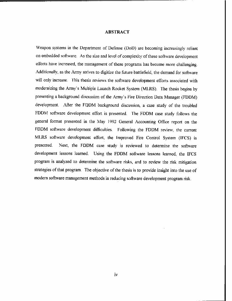
A summarization of the FDDM lifecycle is presented graphically on a timeline
shown in Figure 3.
20
► AFATDS delay generates FDDM mission need as test device
• Original FDDM design found to be insufficient
• FDDM three box design introduced
• AFATDS slips further - FDDM designated as a field able system
• TCU introduced as front end
• FDDM approved forLJRIP
■ Ft SiU C3I demo
1985 1986 1987 1988 1989 1990 1991 1992 1993 1994
• Pre-ISIT at Ft Sill
• Limited Demo at Ft Sill
• FDDM FQT begins
• FDDM ISIT
• Ft SiU Customer Test
* LCU designated as FDDM front end
•1MIT
• Operational Testing
• Fielding
Figure 3 - FDDM Lifccyclc [Ref. 1]
2. Transition to AFATDS
The FDDM is an interim system pending the fielding of AFATDS. The PEO
Tactical Missile Systems (formerly PEO Fire Support) is transitioning the FDDM program
to PEO Command and Control Systems for integration into AFATDS Version 3. The
transition plan, approved in July 1992, includes four major requirements for incorporation
of FDDM into AFATDS:
• Identify unique FDDM requirements that must be incorporated;
• Special application software interfaces;
• Incorporate weapon special applications software; and
• Incorporate utilities special applications software. [Ref. 1, p. 1-5]
21

B. FDDM CONCEPT
This section presents the FDDM concept by describing the FDDM general concept
and components, and operational concept.
1. General Concept and Major Components
The FDDM is fielded in two configurations: a track mounted version for all
echelons of selected MLRS units, and a truck mounted version for selected units above
the battalion level. The FDDM augments TACFIRE and early versions of AFATDS. It
provides a subset of the planned AFATDS functionality for advanced rockets, missiles,
and their submunitions. It is also an automated interface and focal point for target
intelligence and targeting information gathered from the full range of battlefield
intelligence systems. Devices that "talk" in TACFIRE message formats (such as the
AN/TPQ-36A Firefinder) can interface with the FDDM. The FDDM components are
listed in Figure 4. [Ref. 1, p. 2-1]
Fire Direction System
• Lightweight Computer Unit • Combat Net Radio with Comsec • Power Supply (110 v) • Printer • Cables • Installation Kit • MLRS Ada FDS Software
Fire Direction Adaptation Equipment
• Communications and Data Processing • Power Conditioning Unit • Cables • Installation Kit • CDU/DPU Software
Fire Direction Data Manager
Figure 4 - FDDM Component Overview [From Ref. 1, p. 2-1]
22

The Fire Direction System consists of an LCU and the MLRS Ada FDS software.
The FDS provides computational and graphical capabilities, and the man-machine
interface for the FDDM system. The major components of the Fire Direction Adaptation
Equipment (FDAE) are the Communications and Data Processing Unit (CDPU), Power
Conditioning Unit (PCU), associated installation cables and the CDU and DPU software.
The Program Load Unit (PLU) is available as a special tool for loading and upgrading
software systems. [Ref. 1, p. 2-2]
The CDPU consists of a Communications Distribution Unit (CDU) and a Data
Processing Unit (DPU). Each of these units is based on the ruggedized MicroVax chassis.
The PCU conditions and supplements the power provided by the M577 (command and
control vehicle) and can provide temporary power to the CDPU if the vehicle power is not
available. The PCU consists of an electronics box and a battery box containing two 12
volt batteries. [Ref. 1, p. 2-2]
Both the CDU and DPU software is written in Ada, and runs on the corresponding
unit (either the CDU or the DPU) within the CDPU. The CDU software provides the
communications processing logic. The DPU software provides the MFOM specific
processing. The DPU software is further divided into a Common Applications Program
that provides a set of utilities that are both common and shared by all munitions, and the
munition specific programs. [Ref. 1, p. 2-2]
The PLU is included as a basic issue item of the FDDM system and is the same
item that is issued to deep attack capable MLRS units as a special tool. Its purpose is to
provide the capability to download software and tactical messages from the FDDM to
cassettes that can be taken to the M270 launcher for uploading the IEU. Figure 5 shows
the total FDDM system configuration. [Ref. 1, p. 2-2]
23

Fire Direction Data Manager (FDDM)
AN/GYK-37
Lt Weight Computer Unit
Printer/Plotter
Power Supply
Carrier
I FDAE Inst Assy Comms
CDPU Power
Cond Unit
Battery Box
Electronic Box
Cable Assemblies
Radio Set ANA/RC-92A
Inst Kit MK2333A/RC
Figure 5 - FDDM System Configuration [Ref. 1, p. 2-6]
2. Operational Concept
The FDDM concept emphasizes distributed MFOM command and control (C2)
operations. Distributed processing involves many different computers and applications
executing at different echelons of MLRS within the corps area of operations. The FDDM
is capable of configuring its software based on the MFOM payloads that are available to
its subordinate units (batteries or launchers) through the use of Special Application
Programs (SPAPs). [Ref. 1, p. 2-3]
The same FDDM performs Fire Support Element (FSE), field artillery brigade,
MLRS battalion, or MLRS battery functions depending on the operator's input. The
FDDM operational concept implements this strategy by standardizing the hardware and
software across the various MLRS echelons. Personnel transferred between MLRS
echelons should not require extensive training in a new system since they will not be
working with a different system, just different functions of the same system.
[Ref. 1, p. 2-3]
The FDDM allows either the operator or the computer to set time intervals for the
execution of stored time-related fire missions. This capability supports the execution and
24

transmission of large numbers of fire plan targets. A tracking mechanism, accounting
"processing time" by large mission and munition, permits the automatic calculation of
appropriate application '"wake up" times to insure that fire mission time-to-fire, time-on-
target, and no-later-than times are met. [Ref. 1, p. 2-3]
The FDDM provides a library of message formats, battlefield geometry, friendly
unit position data, targets, fire missions, fire plans, threat information, terrain data, and
munitions data. The data stored may include cannon and air asset data as well as rocket
and missile data. The FDDM maintains resource status relationship information (i.e.,
planned fire mission, timed fire missions not in a plan, and available launchers) of assets
allocated to tasks for a total of 96 hours (versus the previous 24 hour capability of
TACFIRE). Upon demand, a unit's ability to accomplish and plan operations can be
calculated and displayed or transmitted. Additionally, "what if exercises are allowed
which will not impact the existing "real" database. An example of this capability would be
to enter an additional fire unit and recalculate the schedule of fire to assess the impact.
[Ref. 1, p. 2-3]
The FDDM enhances the communications capability and the technical and tactical
fire control capabilities of the battalion and battery. The FDDM at the brigade-corps-
division echelons emulates the function of the Variable Format Message Entry Devices
(VFMEDs) and provides deep fires planning capabilities. The corps MLRS battalions will
be the primary delivery units for the MFOM weapons and will provide fires in General
Support (GS) of the corps and General Support-Reinforcing (GS-R) to selected division
artillery units within the corps area. Under centralized control, the corps FSE, in
coordination with the corps tactical operations center support element, will provide target
planning and engagement data to the MLRS battalion via TACFIRE/AFATDS on
established FM, high frequency, or other communications nets. [Ref. 1, p. 2-3]
Based on the commander's guidance and attack criteria, a "quickfire" channel
linking the target acquisition device directly to the MLRS battalion or battery (i.e.,
decentralized control) may be established to facilitate rapid engagement of certain
25

relevant, high-payoff targets such as theater ballistic missile (e.g., the SCUD missile)
launch sites. All that is required to establish this linkage is that the target acquisition
device "talk" in TACFIRE message formats. FIREFINDER is one example of a target
acquisition device that possesses the capability to interface directly with FDDM.
[Ref. 1, p. 2-3]
3. Special Applications Program (SPAP) Concept
The Special Applications Programs (SPAPs) divide the weapon specific processing
from the Common Applications (CA) processing software running within the DPU. This
architecture is depicted in Figure 6. Each SPAP communicates with the CA software
through a structured and documented interface. The Fire Direction Data Manager
Executive Summary [Ref. 1, p. 2-8] lists the following advantages of this architecture:
a. Real Time Configuration of DPU Software
The user invokes only those SPAPs that are necessary to support the
assigned mission. The DPU software runs faster in this configuration than in a
configuration that automatically loads all of the software. The faster execution time is due
to the reduced number of active programs that have to be serviced by the DPU operating
system.
b. Allows Unlimited Number of SPAPs to be Added to the System
The current FDDM architecture allows ten SPAPs to run concurrently.
There is no limitation on the total number of SPAPs developed. This approach also allows
the development of the CA software package without knowing the requirements of future
munitions. This allows the tailoring of munition specific applications as the munition
matures into a fielded system.
26

CDU and External System/Components
DPU Common
A pplications
D D
atab Nee
gital Map ase B ased on ds of SPAP
Digital Map Database
W eapon 1 SPAP
(Army TACMS)
Weapon N SPAP
Figure 6 - Common Applications to Special Applications Architecture [From Ref. 1, p. 2-8]
c. Reduces Costs
The costs of software development and maintenance can be reduced based
on reduced lines of code, reduced testing, commonality and reuse of software, and an
open-ended architecture:
(1) Reduced lines of code. The number of lines of code developed
for a munition are less using the SPAP architecture as opposed to each munition
developing its own complete software package. The CA and CDU software are
developed once, then the SPAPs only have to develop and maintain munition specific
software.
(2) Reduced testing. SPAPs require only a limited amount of
testing of non-SPAP software. The SPAP must test the interface with CA, but does not
have to test all of the CA software requirements. Due to the interface architecture, which
limits the SPAP communications only to those CA relevant to a specific munition,
27

software problems associated with a SPAP are generally limited within the SPAP interface
itself, and not the CA.
(3) Commonality and reuse of software. Each SPAP is forced to
use the CA-to-SPAP interface in generally the same way. This approach takes advantage
of the software reuse libraries concept that the Ada programming language provides. This
will tend to lead to a common approach to future SPAP architectures. This common
approach will reduce the number of personnel required to maintain the software. This also
will allow future munitions to build on the proven concepts/architectures of existing
SPAPs by reusing previous SPAP designs.
(4) Open-ended architecture. Allows the FDDM to be fielded
without knowing what the detailed requirements are for future munitions. The CA-to-
SPAP interface is flexible enough to allow the development and integration of new SPAPs
after the initial development of the current FDDM software. [Ref. 1, p. 2-9]
C. FDDM SOFTWARE DESCRIPTION
The significant FDDM software components are the MLRS Ada software, the
Communications Distribution Unit (CDU) software, and the Data Processing Unit (DPU)
software. The FDDM also has low-level device handling software and firmware, but these
are not addressed in this thesis.
1. MLRS Ada FDS Software
The MLRS Ada FDS software runs on the Lightweight Computer Unit (LCU).
The purpose of the MLRS Ada FDS software is to provide tactical and technical fire
control at the various echelons of field artillery rocket and missile units. As employed at
selected MLRS battalion and battery echelons in the FDDM configuration, the MLRS Ada
FDS software provides the SPAP fire control capabilities as in the stand-alone FDS. The
Ada FDS software also provides additional capabilities required for the CDPU interface
and the deployment of the MFOM. [Ref. 1, p. C-l]
28

2. Communications Distribution Unit Software
The CDU software runs on the CDPU's CDU main processor. The purpose of the
CDU software is to provide external message reception and transmission, and internal
message distribution for the FDDM. The CDU software initializes the CDU software and
hardware, establishes and maintains communications with external and internal FDDM
interfaces, verifies and processes messages, and provides built-in test (BIT) capabilities.
[Ref. 1, p. C-l]
3. Data Processing Unit Software
The DPU software runs on the CDPU's DPU main processor. The purpose of the
DPU software is to receive, process, and transmit data through the CDU to the LCU or
remote subscribers. The data contains information concerning fire units, ammunition, and
targets. The DPU, using weapon special application programs, processes fire missions for
the specified munition and target. Additionally, the DPU software schedules time-related
missions prior to the target becoming an active fire mission. In this way, the DPU
software is used for management of fire support assets and battle planning.
[Ref. 1, p. C-l]
The DPU software consists of several software packages that can be run
simultaneously on the CDPU's DPU main processor. Common Applications are run in the
DPU to support the SPAPs. The following describes each of the DPU software packages.
a. Common Applications
The Common Applications (CA) initializes the DPU software and
hardware, establishes and maintains communications with the CDU, provides a set of
common utilities that weapon SPAPs processing require, and provides built in test (BIT)
capabilities. The following are the major common utilities that CA provides:
29

• Maintains databases containing information about units, munitions, and tactical
plans/situations;
• Activates SPAPs programs as needed;
• Provides software utility libraries for math and character functions; and
• Provides generic fire mission planning and execution. [Ref. 1, p. C-l]
b. Digital Map
In order to meet the special data requirements of enhanced systems,
computer software within the FDDM must be able to access terrain elevation data. This
requirement has been identified as the Defense Mapping Agency (DMA) Level I Digital
Terrain Elevation Data (DTED). To provide the DTED, the CDPU requires the DMA
program to access processed DTED from external media, select the data for a defined
area, and transfer that data to the internal storage device. The DTED is placed on external
media using the DTED compressor utility. The operator requests the DTED of a specified
area to be loaded onto the internal storage device (removable hard drive) so that other
special applications programs may access the data. The digital map SPAP, associated
programs, and data files reside on the internal storage device for immediate processing of
requests for elevation data. [Ref. 1, p. C-2]
c. ATACMS
The ATACMS SPAP provides critical information through a series of
messages that assist the commander in the planning and employment of ATACMS. The
ATACMS SPAP provides the FDDM operator with ATACMS effects, number of rounds
to fire, missile location and altitude. Missile location and altitude information facilitates air
space coordination with the Air Force (a deficiency identified during Desert Storm
operations). The ATACMS weapon has extended range capabilities that can be exploited
using an extended range algorithm provided by the ATACMS SPAP. The ATACMS
SPAP is envisioned being employed only at the C2 node (corps FSE) responsible for
30

planning ATACMS missions, but can easily be provided to lower echelons if operationally
required. [Ref. 1, p. C-2]
d Generic Weapon
The Generic Weapon (GW) SPAP is used to simulate future munition
special applications for testing purposes. The following are some of the ways that the GW
SPAP may be used to support testing:
• Exercise the DPU CA software interface;
• Simulate the processing required by future weapons; and
• Simulate additional MFOM weapons during field testing. [Ref. 1, p. C-2]
This chapter presented background information including the FDDM program
overview, the program history, a description of the system operational concept, and the
FDDM system software. Additional information describing the operational employment
concept of the FDDM is given at Appendix. The chapter that follows will present a case
study of the events and conditions leading up to the 1992 GAO report on the FDDM.
31

32

III. CASE STUDY OF THE MLRS FDDM SOFTWARE DEVELOPMENT
In May 1992, the General Accounting Office released its report, Software
Development Problems Delay the Army's Fire Direction Data Manager. The report cited
software performance problems, schedule delays, and cost overruns as summarized by the
following:
Due to software development problems, FDDM software is not complete, the prime contractor's development costs have tripled from $8 million to over $24 million, and the program is more than 2 years behind schedule. Existing software problems that need to be corrected before FDDM is deployed could push costs and completion dates even further from original projections. [Ref. 2, p. 1]
This chapter provides a case study of the FDDM software management decisions prior to
1992, and documents the program achievements from that point through the successful
system fielding in 1994.
A. CASE BACKGROUND
This section provides further background to the FDDM software development case
study in addition to that introduced in the previous chapter. The development timeframe,
program management structure, and development strategy will be discussed.
1. Development Timeframe
The FDDM was originally intended as a "hybrid test device" to support the
operational testing of the ATACMS. Because of this, neither a mission needs statement
nor operational requirements document were written to document the early system
requirements. The test device, designated as the FDDM in 1986, was needed to mimic the
command and control operations of AFATDS, which would not be available to support
the ATACMS operational testing in 1990. The "hybrid" design consisted of the existing
MLRS FDS and a modified IEU (from the M270 launcher) with the software resident on
33

the IEU principally for the handling of message traffic. A firm-fixed-price contract was
awarded to the MLRS launcher's prime contractor in 1986 to develop and build seven
FDDMs at a price of approximately $8 million. Delivery of these systems was required to
coincide with the ATACMS operational testing in 1989. [Ref. 8]
Following significant technical requirements changes resulting from the designation
of the FDDM as a fieldable system in 1987, the FDDM development schedule was
released from the ATACMS operational test schedule and progressed as a stand-alone
system. Fielding of the FDDM as an interim system for the AFATDS was scheduled to
take place in 1993, subsequent to ATACMS operational testing. [Ref. 1, p. 1-3]
2. Program Management
The FDDM (as originally intended) was designed as a modification to existing
MLRS field artillery command and control devices to support the ATACMS operational
testing. Government management of the development effort resided within the MLRS PM
office because of their experience with MLRS hardware and relationship with the MLRS
launcher's prime contractor. Funding for the FDDM development came from the
ATACMS test budget. Both the MLRS project office and the ATACMS project office
were assigned to the Program Executive Office for Fire Support (now Tactical Missiles),
located at Redstone Arsenal, Alabama. [Ref. 8]
In 1987, the AFATDS PM announced a further slip in schedule that indicated that
AFATDS would not be available when ATACMS was fielded. In order to keep the
ATACMS program on schedule (with operational testing in 1990 followed by deployment
in 1991), the Army Deputy Chief of Staff for Operations directed that the FDDM be
fielded in limited quantities (31 systems) as an interim for the AFATDS. This decision
also required that FDDM support other missiles and munitions which were under
development at that time. [Ref. 1, p. 1-3]
In order to support development of the FDDM as a fieldable system that would
support not just ATACMS but BAT, SADARM, and TSSAM as well, the MLRS PM
34

formed a product management office to oversee the FDDM. The M270 Family of
Munitions Command, Control, Communications, and Intelligence (MFOMC3I) Product
Manager1 position was created within the MLRS project office to provide this program
oversight. The product management office consisted of the MFOMC3I PM (a US Army
lieutenant colonel) with matrix support tasked from the MLRS project office. An
organization chart depicting the FDDM product management office structure and its
relationship to the MLRS PM office is shown in Figure 7. [Ref. 8,1]
MLRS Project Manager
L
Hardware Engineering
Software Engineering
MFOMCI Product Manager
Tech Mgt/ Deputy PM
Program Management
Contracting
MLR 5 Project Manag ement Office Matrix
Figure 7 - FDDM Product Management Office Structure
3. Development Strategy
The original FDDM development strategy was very limited. At the time, it was
believed (by both the Army and the prime contractor) that the basic (i.e., "two box")
design for the FDDM could provide the command and control requirements for the
ATACMS operational testing with minor modifications and limited development testing.
1 Throughout the literature and this thesis, the title "MFOMC3I PM" is referred to simply as the "FDDM PM'. The FDDM development effort was the primary role of the MFOMC3! PM.
35

For this reason, the FDDM development was not tracked and reported under the
requirements of DoD Standard 1521B, Technical Reviews and Audits for Systems,
Equipments, and Computer Software. According to LTC Mario Cervantes, the most
recent FDDM product manager:
At the time, the FDDM was not a product; it was a test device to support ATACMS. We used a fixed price contract with (the prime contractor) that said, basically, 'Modify this government furnished equipment and write a small piece of software that will do what AFATDS is supposed to do for ATACMS'... We weren't really interested in how (the prime contractor) did it, so long as they got it done on time. ...the MLRS PM had a number of contracts open at any given time that didn't report under (DoD Standard) 2167A or 1521B. [Ref. 8]
When the requirement for the FDDM changed from that of a test device for
ATACMS to a fieldable system supporting all of the munitions in the MFOM, the FDDM
PM took steps to formalize the FDDM oversight structure with the prime contractor. A
series of government-supervised development tests and demonstrations were scheduled to
determine the feasibility of the existing design against the growth in requirements to
support the additional munitions. These tests indicated that the planned FDDM hardware
configuration could not support the requirements of the additional munitions in the
MFOM.
As summarized in Figure 8, at this point the accumulation of changes to the
FDDM requirements essentially constituted a change in scope. The FDDM was no
longer to be a test device to support ATACMS only for operational testing, but a fieldable
system required to support the basic MLRS functionality as well as ATACMS, BAT,
TSSAM, and TGW. [Ref. 10]
Because of the significant hardware and software development complications
resulting both from the requirements growth and the changes required for a fieldable
system, and based on the poor testing results achieved up to that time, the FDDM was
separated from the ATACMS operational test schedule in October 1989. [Ref. 1, p. 1-3]
36

Requirements prior to designation Requirements following desgination
as a fieldable system... as a fieldable system...
• Test device/AFATDS mockup • Fieldable svstem with commensurate • Support ATACMS functionality safety, logistics, training, documentation
only fc^ and interface requirements
• Hosted on existing hardware ^ • Support full MFOM functionality • Minimal software development including basic MLRS, ATACMS, BAT
TSSAM and TGW • Hosted on existing hardware with unique
hardware requirements to be added • Extensive software development
Figure 8 - Summary of FDDM Requirements Changes
Because the FDDM had become a fieldable C3I system, instead of a missile test
device, the FDDM PM consulted with the US Army Communications and Electronics
Command (CECOM) Fort Sill Center for Software Engineering beginning in late 1989.
The Fort Sill Center is the Army's experts for development of fire support software C I
systems, and would ultimately be the life cycle software support center for the FDDM. In
June 1990, the Fort Sill Center contracted with Telos to assist the FDDM PM in an
independent verification and validation (IV&V) capacity. Information regarding the
FDDM software development (to include subsequent software release packages) were
forwarded through the Fort Sill Center to Telos. In this way, Telos was given progressive
release packages of the FDDM software to evaluate. [Ref. 8]
The firm-fixed-price nature of the original FDDM contract bound the prime
contractor to continue performing under the terms of the contract. While the changes
mentioned previously amounted to a change in scope [Ref. 10], this was not contested by
the prime contractor. Rather, as a result of mutual consent by both the Government and
the prime contractor, the original contract was repeatedly modified to encompass the
additional requirements. These changes, plus the addition of Telos as an IV&V
37

contractor, greatly increased the price of the FDDM development (discussed in greater
detail in the following section). [Ref. 8]
Throughout 1990, the prime contractor continued to experience software
development difficulties with the data processing software and, according to the FDDM
PM, "...was considerably behind schedule." [Ref. 8] The Fort Sill Center advised the PM
that Telos (the IV&V contractor) was confident that they could complete the data
processing software development and deliver the full FDDM functionality "...within six to
twelve months." [Ref. 10] Telos had considerable experience in developing other fire
support command and control software systems, and further benefited from their
collocation with the Fort Sill Software Development Center and the user community (the
US Army Field Artillery School).
In March 1991, the FDDM PM accepted the latest incremental release of the
FDDM software from the prime contractor. This release, designated as package 8, was
tested informally during a preliminary independent system integration test (pre-ISIT). The
pre-ISIT identified numerous problems with the data processing software, and the test had
to be canceled in July 1991 due to incompleteness of the software. [Ref. 2, p. 6]
In August 1991, the FDDM PM granted a conditional release of the package 8
software to the Fort Sill Center for Software Engineering. The Fort Sill Center in turn
contracted with Telos for final development of the FDDM software. The Fort Sill Center
was well positioned to assume control of the remaining FDDM software development as a
result of its involvement in reviewing the software progress from the prime contractor for
the previous twelve months. [Ref. 10]
The FDDM PM did not terminate the original contract with the prime contractor.
Following conditional acceptance of the package 8 software release, the PM allowed the
contract with the original prime contractor to expire. As mentioned previously, the
remaining software development was performed by the Fort Sill Center. An additional
contract (cost plus incentive fee) was subsequently awarded to Codar for production of
hardware and the remaining FDDM integration effort. [Ref. 8, 19]
38

The Fort Sill Center for Software Engineering significantly accelerated the FDDM
software development strategy by incorporating a series of rapid prototyping
demonstrations with the user community from Fort Sill. The Fort Sill Center established a
software development facility for the FDDM on site by installing the prototype FDDM
hardware and downloading the conditionally released FDDM software (package 8) from
the original prime contractor. Software engineers from Telos worked directly with
representatives from the Fort Sill user community to find and fix the remaining FDDM
software problems. Representatives of the US Army Missile Command Software
Engineering Directorate and the Fort Sill Center Staff maintained configuration control
throughout the "test-fix-test" cycles. [Ref. 11]
In December 1991, an I SIT was conducted at Fort Sill, Oklahoma. This test
demonstrated the basic FDDM functionality while identifying 30 additional software
trouble reports (STRs) [Ref. 11]. These STRs were subsequently identified and fixed by
Telos, and in June 1992, the FDDM PM conducted a successful customer test that
demonstrated significantly better mean time between operational failure rates than required
(317 hours versus 210 hours required). [Ref. 1, p. 1-4]
In May 1993, the FDDM underwent combined operational testing as part of the
TACFIRE Version 10 operational testing at Fort Sill, Oklahoma. The following summary
was extracted from the conclusions and recommendations paragraph of the FDDM
conditional release approval based on the interim abbreviated operational assessment,
performed by the Army's Operational Evaluation Command (OEC):
Overall Conclusions. Operationally, the FDDM is marginally effective and marginally suitable. The FDDM effectively replaces the functions of the currently fielded FDS as a command and control system, however, has shortcomings in providing some of its enhanced capabilities. The most significant problems were in processing fire plans and transmitting weapons effects data for special applications. Workarounds have been identified for these effectiveness shortcomings. Deficiencies in TM (technical manual) coverage of error warning messages, lack of collective training, and poor printer performance are the most significant problems in relation to system suitability. [Ref. 12, attachment E]
39

The conditional release of the FDDM was principally due to existing
shortcomings in several classified weapons SPAPs. According to the FDDM PM, these
shortcomings had no effect on the ATACMS or MLRS DPICM SPAPs, but were
sufficient to warrant the system description as "marginally effective". Because none of
these classified systems had yet been fielded, and because of the modular design of the
SPAP architecture, there was no reason to withhold fielding of the FDDM in the interim.
The performance difficulties of each of these SPAPs was corrected or resolved in the six
months following the conditional release. [Ref. 8]
The test results were found to be sufficient to grant conditional release of the
FDDM and are summarized by the FDDM PM in the following:
The May OT (operational test), the FDDM's most important test of the year, took place using US Army soldiers in a tactical environment at Fort Sill, Oklahoma. As a subset of the TACFIRE Package 10 OT, the FDDM very successfully participated in phases III and V of a five part test. The third phase consisted of an FDDM system test and the fifth phase tested the FATDS system's ability to interface with one another. [Ref. 13, p. 5]
In August 1993, the MICOM Materiel Release Review Board (MRRB)
conditionally approved the FDDM for fielding. The package was forwarded to the US
Army Materiel Command (AMC) where release was approved in September 1993.
[Ref. 13, p. 5]
Materiel release approvals at MICOM and AMC were the last steps necessary for
tactical fieldings to begin. The contractor had been prepared to start equipment
installations and the ceremony to hand off the first tactical FDDM to the 75th Field
Artillery Brigade took place on 27 September 1993. The FDDM initial operational
capability (IOC) occurred with the fielding of the 6th Battalion, 27th Field Artillery
1 Following several "neck down" decisions by the PEO Tactical Missiles and at the order of the Assistant Secretary of the Army, Research, Development, and Acquisition, the TSSAM, TGW, and GLTR programs were canceled or significantly restructured as of June 1992. This obviated the need to incorporate these requirements into the FDDM SPAPs. [Ref. 16]
40

Battalion, at Fort Sill on 28 October 1993. At the conclusion of fieldings in July 1994, a
total of 31 tactical FDDM systems had been fielded. [Ref. 13, p. 5,6]
This section consisted primarily of a more detailed background of the history of
the FDDM and the management decisions that led to the successful fielding of the system
in 1993 and 1994. In the next section, the software development, project cost, and project
schedule problems experienced by the FDDM program prior to May 1992, will be
discussed in greater detail using the May 1992 GAO report as a guide.
B. SOFTWARE DEVELOPMENT PROBLEMS, SCHEDULE DELAYS, AND COST INCREASES
The purpose of this section is to document the software development, project cost,
and project schedule problems experienced by the FDDM program as of May 1992 (the
date of the GAO report on the FDDM). The references for this section are the GAO
Report to the Chairman, Subcommittee on Research and Development, Committee on
Armed Services, House of Representatives, Embedded Computer Systems: Software
Development Problems Delay the Army's Fire Direction Data Manager [Ref. 2] and the
formal response sent from the FDDM PM (via the Fire Support PEO) to the Office of the
Under Secretary of Defense for Acquisition3 [Ref. 14].
1. Software Development Problems
The GAO report states that the FDDM development effort had encountered a
number of software development problems since 1986. The software development
problems were demonstrated at key program test and demonstration points cited by the
GAO report as follows: the decoupling of FDDM from ATACMS operational testing in
1989, preliminary independent systems integration testing (pre-ISIT) in March 1991, fire
These two documents are henceforth referred to as "the GAO report" and "the PM's response".
41

direction and data processing data base synchronization, and problems uncovered during
the FDDMISIT in December 1991. [Ref. 2, p. 6,7]
a. Decoupling of FDDM and ATACMS Operational Testing
The first significant example of the FDDM's software development
problems, as cited by the GAO, was the failure of "...a critical field test in 1989" that led
to the system's exclusion from the ATACMS operational testing. [Ref. 2, p. 6] The
"critical field test" was the C3I demonstration conducted at Fort Sill, Oklahoma in
September 1989 [Ref. 1, p. 1-3]. According to the GAO report, the cause of this testing
failure was that "...its (the FDDM) communications software would not work and had to
be rewritten and its data-processing software was not completed in time to be used in the
field test - and was unable to support the missile's (ATACMS) operational tests held later
that year." [Ref. 2, p. 6]
The PM's response to this issue states that the C3I demonstration was intended to
test the capability of the FDDM hardware configuration with the original BCU front end.
Since the purpose of these tests was primarily testing of the hardware configuration, the
data processing software was not planned as part of the test. [Ref. 14, p. 2] The Army
was considering replacing the BCU with an alternative, the TCU (transportable computer
unit) common hardware. These tests validated that the BCU was insufficient as a front-
end processor for the FDDM. [Ref. 1, p. 1-3]
According to the FDDM product manager, the data processing software was not
complete at the time of the C3I demonstration. The last of the C3I demonstrations was
canceled due to unavailability of the data processing software. This was the primary
reason that the FDDM was decoupled from the ATACMS operational testing. [Ref. 8]
b. Pre-ISIT in March 1991
The pre-ISIT is addressed in the GAO report as follows:
In March 1991, preliminary integration testing was performed on updated data-processing software. However, the software was still
42

incomplete. It could not run the approved test procedures and had to be modified before testing could be resumed. In July 1991, the Army had to cancel this testing because the fire direction system did not have the capacity to handle high volumes of messages, and the system would therefore shut down. [Ref. 2, p. 6]
The PM's response states that the pre-ISIT was conducted as a "...series of test-
fix-test cycles" intended to find problems with the software. The PM's response attributes
"a significant number of the issues" associated with this test to the BCU front end
processor. According to the PM's response, the Army had already decided to use the
TCU front end (now the LCU) as the front end for the FDDM. [Ref. 14, p. 2]
c. Fire Direction and Data Processing Data Base Synchronization
According to the GAO report, the pre-ISIT uncovered difficulties in
keeping the fire direction and data processing data bases synchronized during fire
missions. Without this synchronization, the data processing system would not have
accurate data on launcher status and assignments. [Ref. 2, p. 6]
The PM's response states that the synchronization problems were attributable to
the use of the BCU during these tests. The TCU, with larger memory and faster
processing power, overcame the problems associated with data base synchronization in
later tests. [Ref. 14]
d. Problems Uncovered During the December 1991ISIT
The GAO's review of the December 1991 ISIT indicated that a number of
FDDM's software problems had not yet been addressed. The GAO report states that,
during periods when high firing rates were required, the data manager experienced
communications bottlenecks due to the large number of messages being transmitted.
[Ref. 2, p. 7]
The PM's response indicates that the bottlenecks were the result of intentionally
stressful test scenarios that were designed to test the FDDM to its operational limits.
43

According to the PM, the I SIT tests showed that the FDDM exceeded its message
handling requirements, as evidenced by the following statement:
...the FDDM exceeded its required mission rate and that the bottlenecks only occurred in planned overstress test environments designed to find such bottlenecks. In the I SIT, the FDDM met the fire mission processing requirements of the European scenario which had a considerably higher fire mission rate than the Post Cold War mission scenario. [Ref. 14, p. 2]
2. FDDM Development Costs
The GAO reported that the costs to develop the FDDM had increased from $8
million in 1986 to an estimated $50 million by 1992. According to the GAO report:
Because the original FDDM contract did not require separate identification of software development costs, it is difficult to estimate exact costs or cost growth. However, the Army estimates that original contract costs have increased from $8 million to about $24.5 million, with most of these increases due to added requirements. In addition, the Army has spent another $25 million beyond its original estimate to contract for services such as engineering assistance, and independent verification and validation. [Ref. 2, p. 7]
According to the PM's response, the development costs for the FDDM grew for
the following reasons:
FDDM costs have grown as reported. However, changes in the mission and planned FDDM utilization have been the driver. The FDDM was originally contracted as a demonstration/test device to provide command/control interface during development testing of the Army's suite of long range missiles and smart munitions. When the Army decision was made in 1987 to upgrade the FDDM into a fieldable system to support the ATACMS missile, as well as the other missile systems under development at that time, the mission requirement and associated costs of the FDDM were raised significantly. The change to a fielded system added previously unfunded requirements for documentation, environmental protection, qualification testing, logistic support, and the other requirements associated with fielding a system. These requirements significantly raised oversight requirements and therefore the support services cost. [Ref. 14, p. 3]
44

3. FDDM Development Schedule
The GAO report states that the Army intended the FDDM to be ready by 1989 in
order to support the ATACMS operational tests. The FDDM did not support the
ATACMS operational testing, nor was it ready for ATACMS fielding in 1990. While the
missile can function without the FDDM, it cannot be fired rapidly when needed. By 1990,
the planned deployment date for the FDDM had been further slipped to January 1993.
The GAO report further states:
The contractor delivered communications software in May 1991, but due to software problems the Army postponed the delivery date for the data-processing software until May 1992. Without the data-processing software, FDDM is not functional. As of April 1992, FDDM was still undergoing development and testing, and the Army had delayed FDDM deployment from January 1993 to June 1993. [Ref. 2, p. 7]
The PM's response states that the software had completed all testing and had met
the requirements necessary to support a fielding decision. The reason the deployment date
was slipped ten months was "...to take advantage of a 60% production cost savings
obtained by using the latest version of the Army common hardware computer, the
Lightweight Computer Unit (LCU)." [Ref. 14, p. 3]
The GAO report included remarks concerning the FDDM PM's decision to
transition the system software development management to the Fort Sill Center for
Software Engineering. The GAO report indicated concern for the system schedule in light
of the switch to a different contractor, as illustrated by the following:
This organization (the Fort Sill Center), however, is not using the original FDDM contractor and has brought in another contractor (Telos). The new contractor is familiar with some of the FDDM system but will have to learn how all the FDDM components work together before solving FDDM's existing problems, and completing FDDM testing may affect FDDM's deployment schedule. [Ref. 2, p. 7]
According to the PM's response, the Fort Sill Center had been identified
previously as the life cycle software support center for the FDDM and had been receiving
completed work packets from the prime contractor throughout development. The PM
45

defended his decision to transition the final development of the FDDM to the Fort Sill
Center as follows:
The product office directed the FDDM designated post deployment software life cycle support center to take over the software development under the product office's management. This decision was made because of the new contractor and the need to get the software on schedule. The new contractor (Telos) was considered a positive move because of their demonstrated performance. The results of this move have been that the software development was completed on schedule and successfully tested during the June 1992 customer test. [Ref. 14, p. 4]
C. FDDM SOFTWARE DEVELOPMENT MANAGEMENT
The GAO report stated that the FDDM software development suffered from poor
management, as exemplified by the following extract from the GAO report:
Many of FDDM's problems have occurred because the Army did not effectively manage the FDDM software development effort. Specifically, it did not provide detailed requirements in the original 1986 contract or promptly enforce Defense standards for software development, and it continued to add functional requirements that further delayed development. The contractor added to these development problems with poor testing in some areas. [Ref. 2, p.8]
This section addresses management issues associated with the FDDM software
development. The discussion will be presented through a review of the following GAO
findings: that the FDDM functional requirements were not well-defined or controlled, that
Defense standards were not enforced, and that contractor testing was inadequate and
delayed development. Though not addressed by the GAO report, this section will also
discuss the prime contractor's software development capability and its sufficiency in
meeting the requirements for the FDDM.
1. FDDM Functional Requirements Definition/Control
The GAO report states that the Army did not provide sufficiently detailed
functional requirements in the original 1986 contract. Poor functional requirements
46

definition was cited by the prime contractor's software development manager as "...the
major problem with FDDM development." Between 1986 and 1991, the Army continued
to add requirements, which required additional software development. These additions
were principally to support additional weapon systems that the FDDM would control.
According to the GAO report, "The first FDDM product manager agreed that the
additional requirements caused delays in the development schedule." [Ref. 2, p. 8]
The PM's response states that the "additional requirements" were actually "...a
complete change in the mission and objective of the FDDM system." [Ref. 14, p.4] This
period is consistent with the timeframe when the FDDM went from that of a test device to
a fieldable system (1987). As the GAO report states, these additions incorporated the
additional weapons and munitions that the FDDM would support in a fielded environment.
An additional complicating factor associated with the requirements growth
experienced by the FDDM was the nature of the new weapons being incorporated during
this period. At the time these requirements were generated, the TSSAM, BAT, and
Ground Launch Tacit Rainbow (GLTR) programs were special access programs (SAP),
commonly referred to as "black programs." Design information, requirements, and
weapon characteristics were restricted information. According to Mr. Raymond
Pietruszka, lead engineer for the FDDM, this made incorporation of the programs into the
FDDM more challenging, as indicated by the following:
First of all, we didn't even know about these programs, or know who they were, or where they were at. One day, a guy comes in, briefs us, and says, 'Sign this piece of paper.' Now we have to incorporate this into our design. But, we couldn't just pick up a phone and call a SAP program and have them tell us what we needed to know. Just trying to get together for a meeting would take weeks. And then, at the meeting, their engineers would say something like, "We can't tell you about that, you don't have access to that area." [Ref. 10]
This view was confirmed in an interview with Mr. George Williams, Program Executive
Officer (PEO) for Tactical Missiles (formerly Fire Support). Mr. Williams agreed that a
substantial portion of the development problems encountered in the MFOM integration
47
effort in general, and the FDDM in particular, was attributable to the restrictions required
in SAP programs. [Ref. 15]
2. Enforcement of Defense Software Standards in FDDM Development
The GAO report states that the Army required the contractor to follow DoD
Standard 1521 (Technical Reviews and Audits for Systems, Equipment, and Computer
Software) during the software development effort, "...but did not promptly enforce its
provisions." According to the GAO, this allowed the Army to increase requirements
without controls established by an approved baseline. The GAO report also cites a
requirement in DoD Standard 2167 (Defense System Software Development) for a
software development plan (SDP). According to the GAO, the contractor did not have a
detailed SDP to guide development of the software. [Ref. 2, p. 8]
According to the PM's response, formal specification reviews (such as the
software specification review required by DoD Standard 1521) were not required for the
original FDDM contract. The PM's response states the following:
...in-depth reviews were held for each software specification to insure that both the contractor and Army understood the requirements. While the data processing software specification was not signed by the government until 1989, interim approval had been given to the contractor at the preliminary design review of each software package. [Ref. 14, p. 6]
The PM's response states that the Army did not require incorporation of DoD
Standard 2167 into the original FDDM contract because "...it had not been incorporated
into the MICOM contracts at that time." This oversight was corrected later with the
development of the data processing software, and with the transition to the Fort Sill
Center, which implemented DoD Standard 2167 for the FDDM. [Ref 14, p. 6]
3. Inadequacy of Contractor Testing
The GAO report states that development was delayed because numerous problems
were not detected during the contractor's initial testing. A specific example of the
48

inadequacy of the contractor's testing, as cited by the GAO, was the contractor's use of
hard wired communications in testing where radio link communications were called for in
the system test. [Ref. 2, p. 9] According to Mr. Pietruszka, who was present at this test,
the communications failure could have been avoided by testing the system in the lab before
the demonstration. Mr. Pietruszka states:
The problem with this test was that the modem they (the contractor) installed was too sensitive for use in the noisy FM environment. The modem kept keying on background noise, which would lock up the system. It took us two weeks to figure that one out...all we had to do was reduce the sensitivity of the modems and the problem was fixed. But we didn't find this until we were out on the ranges of Fort Sill...if they (the contractor) had tested their modems in the lab with FM, like they were supposed to, this would have been found earlier. [Ref. 10]
4. Contractor's Software Development Capability
Throughout numerous interviews conducted as research for this thesis,
government program management officials associated with the FDDM expressed their
belief that the contractor did not possess the capability to develop the FDDM software
once the requirements changed from a test/demonstration device to a fieldable system.
While some of the remarks may be attributable to a defense of the PM's decision to
transfer software development to the Fort Sill Center (and the new contractor, Telos), the
consistency of the remarks is pertinent to a discussion of the FDDM's software
management decisions.
When asked whether the FDDM would have been successfully deployed if the
Army had stayed with the prime contractor, LTC Cervantes, the FDDM PM responsible
for the decision to move the FDDM to the Fort Sill Center, replied as follows:
The FDDM would not have made the progress it did, in the timeframe we were working. After giving the work over to the Fort Sill Center, we had maybe six months until the ISIT. When we came through that test (in December 1991) with only a few problems remaining, I thought, 'this is it...we've turned the corner.' You see, this was the very first success that FDDM had; this was the light at the end of the tunnel.
49

Would we have been there if we had stayed with (the prime contractor)? No. I don't think so. [Ref. 8]
Mr. Pietruszka stated the following concerning the software capabilities of the
prime contractor:
The (prime contractor) is the expert when it comes to working on the (MLRS) launcher and the launcher hardware. They were the right guys for the job when the FDDM was nothing but an IEU and FDS. But when the requirement changed to a command and control device for the MFOM, they were out of their league. They just didn't have the software experience to do the job. [Ref. 10]
According to Mr. James Steelman, a systems engineer assigned to the Fire Support
PEO staff during development of the FDDM, the prime contractor did not have the
software capability necessary for the FDDM effort. His remarks included the following:
(The prime contractor) gained a lot of software experience on the FDDM, and the government paid for that experience. They got smart on Ada and we got smart on software in general... I don't think it was just requirements changes that made it tough for the contractor - they didn't have the people and they didn't have the experience that was needed on that program. [Ref. 16]
D. FDDM-AFATDS INTEGRATION EFFORT
Since 1987, when the Army decided that the FDDM would be a fielded system as an
interim for the AFATDS, the FDDM has been required to integrate many of the AFATDS
requirements for advanced missiles and munitions. Because of this, the Army has planned
to transition the FDDM software into the AFATDS software beginning in 1994.
According to the GAO report, as of January 1992, the Army had not made formal plans
for a detailed integration of the FDDM software into AFATDS. The GAO report states
that a formal transition plan is necessary "...to determine how much FDDM software will
be compatible with AFATDS and how much new software will have to be written."
[Ref. 2, p. 10]
50

According to the PM's response, the strategy to transition the FDDM software to
AFATDS is as follows:
First, the TRADOC (Training and Doctrine Command) System Manager for Fire Support Command and Control Systems (TSM-FSC2S) has developed a set of user functional descriptions for the FDDM. Second, PM FATDS, PM MLRS and TSM-FSC2S have agreed to a transition plan. Key actions in the plan are for PM FATDS to perform a requirement trace between the FDDM software, user requirements, and AFATDS, insuring AFATDS Version 2 supports the future incorporation of the FDDM into AFATDS Version 3 and establishing a management structure to oversee the process. [Ref. 14, p. 8]
LTC Mario Cervantes, the most recent FDDM PM, when interviewed for this
thesis in July 1994, indicated that the integration effort was progressing well, as indicated
by the following:
Our plan was to 'grow' the FDDM requirements into the AFATDS in Version 3 starting in Version 2. So far we've been able to do that principally because the FDDM code is written in Ada and is modular. A good deal of credit, though goes to the people at the Fort Sill Center (for Software Engineering) who worked with us and the AFATDS PM in tracing the requirements from our product to theirs...their (the Fort Sill Center staff) knowledge of Fire Support requirements is key to making the transition work. [Ref. 8]
The AFATDS is currently scheduled for initial operational test and evaluation
(IOT&E) beginning in August 1995. According to the current product manager for
AFATDS, the FDDM integration effort has proceeded as planned and will not delay the
expected fielding or functionality of AFATDS. [Ref. 17]
E. GAO CONCLUSIONS AND RECOMMENDATIONS
The GAO report concluded that the increased costs and schedule delays were the
result of the Army's failure to follow required development procedures. In addition, the
GAO report states that the change in software contractor and new software requirements
51

may affect the planned June 1993 deployment of the FDDM. According to the GAO,
additional delays would limit the useful life of the FDDM. [Ref. 2, p. 11]
The GAO recommendations to the Army concerned the PM's strategy for
integration of the FDDM into the AFATDS, and included the following:
• Provide direction for determining how much, if any, of the FDDM software
can be used in AFATDS;
• Establish clear lines of authority and accountability between the FDDM and
FATDS offices for making decisions and resolving problems; and
• Provide specific milestones for actions to accomplish the transition.
[Ref. 2, p. 11]
The PM's response indicates that "not using proper procedures" caused some of
the increased costs and schedule delays, but was "not the sole reason", as indicated by the
following:
In addition to not using proper procedures, the FDDM was affected by the dynamic environment of the period in which several new weapons systems were added to the MFOM, each adding or changing requirements, and the delays experienced by AFATDS which change the very role the FDDM was to play. [Ref. 14, p. 8]
The PM's response defends movement of the software management responsibility to the
Fort Sill Center and the selection of Telos as the contractor for FDDM software in the
following:
While factors beyond the control of the product office may impact the fielding of the FDDM, it will not be its software. The change in contractors has proved to be the best action possible under the condition with the result that the FDDM completed a highly successful customer test in June of 1992. [Ref. 14, p. 8]
F. SUMMARY
The GAO report [Ref. 2] was published in May 1992. Up to that point, the FDDM
program had exhibited numerous software problems including the following:
52

• After numerous tests and demonstrations, the FDDM software was still not
complete;
• The prime contractor's costs had tripled from $8 million to more than $24
million, and the Army had committed an additional $25 million for engineering
services and support contracts; and
• The FDDM program was more than two years behind schedule and had been
decoupled from its original mission of supporting the ATACMS operational
testing.
The GAO report attributed the majority of the FDDM software development
problems to a failure by the Army to follow required procedures. [Ref. 2] The FDDM
PM's response stated that, while the Army's failure to follow procedures contributed
somewhat to the FDDM's difficulties, the principal reason for the FDDM's development
problems was the result of the change in role and mission of the FDDM. [Ref. 14]
Government officials associated with the FDDM development effort indicated that the
prime contractor did not possess the software capability to develop the FDDM software
when the requirement changed from a test device to a fieldable C I system. [Refs. 8, 10,
and 16] The Army's position is that moving the software development from the original
prime contractor to the Fort Sill Center (for software development) and Codar (for
hardware production and integration) was in the best interest of the FDDM program at
that time. These actions ultimately resulted in the successful customer test in June 1992.
In the following chapter, the MLRS PM's development strategy for the Improved
Fire Control System (IFCS) will be reviewed. Similarities and differences between the
software development strategies of the FDDM and IFCS will be highlighted in subsequent
chapters to evaluate the application of lessons learned from the FDDM development
effort.
53

54

IV. THE MLRS IMPROVED FIRE CONTROL SYSTEM DEVELOPMENT
In November 1992, the MLRS project office awarded a sole-source, cost plus
award fee (CPAF) contract to Loral Vought Systems Corporation (LVS) for the
engineering and manufacturing development (EMD) phase on a comprehensive upgrade to
the existing fire control system (FCS) of the MLRS launcher. The upgrade program,
designated as the improved fire control system (IFCS), will modernize the MLRS launcher
and provide it with improved C3I capabilities for operations in deep fire missions on future
digitized battlefields.
The IFCS design is a combination of both hardware and software improvements.
The primary focus of this chapter is a description of the IFCS embedded software
development strategy. While the chapter culminates in a description of the IFCS
embedded software development program, the reader will first be given an understanding
of the overall system development, including the hardware design. The discussion in this
chapter is presented in the following order: the IFCS program background, a description
of the IFCS which details its major hardware and software components, and specific
details of the IFCS software development strategy. In the chapter that follows, the IFCS
software development strategy will be evaluated against the lessons learned from the
FDDM software development.
A. BACKGROUND
This section provides the reader with background information concerning the IFCS
program. The background is presented in the following order: the IFCS requirement; a
general, system-level description of the IFCS; the IFCS development schedule; and a
description of the IFCS management structure and acquisition strategy.
55

1. IFCS Requirement
The original design of the MLRS launcher is nearing 15 years of age. The MLRS
development program was originally proposed in the mid-1970s to counter the "...massive
Warsaw Pact forces arrayed against the NATO forces in Europe." Design of the MLRS
proceeded throughout the 1970s and was finalized at the DSARC IIIA decision in
November 1982. A full-scale production contract was awarded to the initial source in
December 1982. [Ref. 18, p. 1-1, C-8]
Since 1982, the FCS of the MLRS launcher has undergone minor product
improvements to improve component reliability, availability, and maintainability (RAM)
factors. But little has been done previously to modernize the original design to provide
the compatibility needed in terms of data processing speeds, throughput, and flexibility
necessary to keep the launcher current with evolving fire direction systems and future
MLRS munitions. [Ref. 7]
The existing FCS on the MLRS launcher is based on early 1980's digital and
analog technology. The Intel Z80, 8080, and 8088 microprocessors used in the system
have reached their maximum potential. Also, the existing architecture does not support
the standard word sizes that evolving fire direction systems will require (e.g., 32 bit
messaging modes). As a result of this, the existing FCS will soon be considered obsolete
by the Army. [Ref. 9]
In considering the requirement for an upgrade to the FCS, the MLRS PM has
focused on future requirements for digital data transmission and processing. As the Army
moves forward in its initiative to digitize the battlefield, the MLRS launcher will have the
flexibility to operate with the Army's future data interchange protocol. Currently, the
IFCS file transfer protocol will use the Transmission Control Protocol - Internet Program
(TCP-IP). Should the Army protocol change or differ from that currently being pursued
by the IFCS PM, the IFCS protocol can be modified using software. [Ref. 19, p. 19]
The reduction of operations and support (O&S) costs represents an additional
requirement for the IFCS. The IFCS design is intended to reduce the number and skill
56

level of system maintainers and improve the reliability and maintainability of the launcher.
Additionally, with the costs of military-specification hardware costs increasing (due to a
decline in the size of the military industrial base) the IFCS will save on the cost of spare
parts through the use of commercial standards in an "open" architecture. According to
the IFCS product manager, the IFCS enhancement (when fielded with a parallel program,
the improved launcher mechanical system - ILMS) will save approximately $250,000 per
MLRS battery per year. [Ref. 9]
2. IFCS System Description
The IFCS is being developed as a major product enhancement to the existing
MLRS launcher. The IFCS operational environment is depicted in the IFCS system level
diagram shown in Figure 9. The following is extracted from the general description of the
IFCS as provided by the IFCS system specification (commonly referred to as the "A"
specification):
The IFCS enables the MLRS Family of Munitions (MFOM) to interoperate with national fire direction systems. The IFCS shall support this MFOM with the addition of the appropriate missile/rocket manager out of the munition, launcher, or fire direction system employed...The IFCS shall have the on-board capability to conduct built-in test (BIT), receive a fire mission, navigate/determine launcher location, compute firing data, orient on the target, and fire the selected weapons. [Ref. 19, p. 8]
The IFCS design stresses the use of common hardware, software, and standardized
interfaces. The "open" nature of this architecture is intended to negate system
obsolescence or dependence on a specific technology. As fire support technologies
mature, the IFCS is intended to grow to accommodate future requirements. This is
accomplished primarily through the distribution, or modularity, of the overall system
architecture. The following excerpt describes this architecture in greater detail:
The IFCS implementation shall utilize common hardware, software, and interfaces in all line replaceable unit (LRU) designs. LRUs shall allow for technology insertion which mitigates obsolescence and promotes
57

growth. Data buses, buses, processors, and memories shall be implemented using controlled standards and military qualified electronic components...All circuit card assemblies (CCAs) used to implement identical or common FCS functions (e.g., MIL-STD-1553 interface, Institute of Electrical and Electronics Engineers (IEEE) 802.3 interface, power conditioner modules, processor CCAs, memory CCAs, etc.) shall be common and interchangeable between LRUs. [Ref. 19, p. 11]
National Fire Direction Global Positioning System
Operator Fire Control System
Weapons MLPA* Trainer !
* Missile Launch Pod Assembly
Figure 9 - IFCS System Diagram [From Ref. 19, p. 9]
The IFCS functional diagram listing the principle hardware and software
components is shown at Figure 10. IFCS software components are listed in Figure 11. A
description of each of these components will be presented in a later section.
3. IFCS Development Schedule
The IFCS program received approval to enter the EMD phase in November 1992.
A hardware preliminary design review (PDR) and the system design review (SDR) were
concluded during 1993. In fiscal year 1994, the system specification review (SSR),
hardware critical design review (CDR), and software PDR were completed. Currently,
the IFCS program is undergoing engineering design tests. The software CDR will lock in
58

the CSCI designs in August 1995. The complete IFCS development program schedule is
shown at figure 12. [Ref. 9]
IFCS FUNCTIONAL DIAGRAM
INTERCOM
DUAL RADIO SETS
COMSEC
POWER SWITCHING UNIT (PSU)
FIRE CONTROL
PANEL (FCP) (EMBEDDED MSD)
DUAL REDUNDANT MIL STD 1553 BUS
METEOROLOGICAL SENSOR (MS)
ELECTRONIC ASSY TRANSCEIVER ASSY
CONTACT TEST SET (CTS)
(TEST AND PROGRAM LOAD FUNCTIONS)
GPS ANTENNA
ODOMETERS
LAUNCHER INTERFACE
UNIT (LIU)
EMBEDDED MP, CMP AND
PMU FUNCTIONS
LAUNCHER DRIVE SYSTEM
(LDS)
POWER DIST BOX
(PDB)
BOOMS
HOISTS
BOOM CONTROLLER (BC)
POSITION/ NAVIGATION UNIT (PNU)
EMBEDDED POSITION GPS
WEAPON INTERFACE
UNIT (WIU)
COMBINED WIU/ WPU FUNCTIONS
LAUNCH POD
ASSEMBLIES
(LPA1 &
LPA2)
Figure 10 - IFCS Functional Diagram [From Ref. 19, p. 10]
IFCS Software Components
• Communications Management • Launcher Interface • Maintenance Management • Man/Machine Interface • Missile/Rocket Manager
• Missile/Rocket Ballistics Manager • Position/Navigation • Power Management • Weapon Interface • FCS Institutional Trainer
Figure 11 - IFCS Software Components [Ref. 19, Section 3.2.2.2]
59

IFCS SCHEDULE
Design Reviews
Engrg Design Tests (EDT)
Pre Prod Qual Tests
Operational Tests (OT)
Mod Kits
92 93 94 95 96 97 98 98 00 01
A A GO AHEAD SDR
AsSR A A SW CDR
HWraRAHWCDRi
A SW PDR
A PCI
A AECP FQT
I I LOG DEMO
DEVELOPMENT
SYS TEM INTEGRATION
TEST
□-"
EXTENDED SYSTEM
INTEGRATION TEST
MS IHA
A LONG LEAD
LRIP DECISION
COMBINED IFCS/ILMS
A lOTE
KIT DELIVERIES A BEGIN
POT I
Figure 12 - IFCS Development Schedule [From unpublished slides, MLRS Project Office]
The LFCS program will run concurrently with the improved launcher mechanical
system (LLMS) program scheduled to begin in August 1995. The ILMS program will
upgrade the launcher's mechanical systems at the same time the LFCS program modernizes
the launcher FCS. The IFCS will be incorporated into the MLRS launchers using
modification kits. Currently, the MLRS PM is uncertain whether the overhaul kits will be
installed at unit locations or at depot maintenance facilities. The kit installations and
ILMS overhauls are scheduled to begin during the third quarter of fiscal year 2000.
[Ref. 9]
4. IFCS Management Structure and Acquisition Strategy
The LFCS is a major product improvement to the existing MLRS launcher, and is
considered an acquisition category (ACAT) III program. The system development is
being managed by the MLRS Project Management Office within the Program Executive
60

Office, Tactical Missiles, at Redstone Arsenal, Alabama. An Army system product
manager position has been created for this system, and is currently filled by a GM-15
civilian Department of the Army centrally-selected product manager. [Ref. 9]
The Government IFCS product management team is similar to the former FDDM
product management structure. The IFCS PM office consists of the product manager with
matrix support from the MLRS project office. The current product manager is the former
deputy/chief of technical management from the FDDM program. Hardware, software,
contracting, and program management support is supplied by the MLRS PM matrix staff
from the ground support branch, software engineering branch, acquisition management
branch, and program management staff, respectively. [Ref. 9]
The prime contractor and integrator for the IFCS is LVS, located in Dallas, Texas.
The Government issued a CPAF contract, with a maximum price of $137 million, to LVS
for the EMD phase of the IFCS development. LVS has subcontracted to Raytheon for the
meteorological sensor, and Allied Signal for the position and navigation unit. Total
procurement authority for the IFCS program is currently estimated at $750 million. The
procurement strategy for the IFCS has not yet been published. [Ref. 9]
B. DESCRIPTION OF THE IFCS COMPONENTS AND FUNCTIONS
This section describes in greater detail the function of the IFCS components
(referred to as line replaceable units, or LRUs) and computer software configuration items
(CSCIs). The primary reference for this section is the system specification for the IFCS
(reference 19). The descriptions presented are extracted from the paragraphs that specify
the system components' requirements allocation (for LRUs), and the segment definitions
(for CSCIs). The discussion addresses the hardware components first, followed by the
software components (CSCIs).
61

1. IFCS Hardware Components
This section describes the functions and requirement allocations for the primary
LRUs in the IFCS.
a. Fire Control Panel (FCP)
The primary purpose of the FCP is to provide the man/machine interface
(MMI) function for the IFCS. The FCP will consist of a display, alphanumeric keypad,
toggle switches, and light emitting diode (LED) indicators. The display will be capable of
providing the operator with both alphanumeric and real time video information. Because
the MLRS is an international program, the display and keyboard must be capable of being
configured in multiple languages. All IFCS functions will be controlled through the FCP.
These include system power, resource allocation, communications, and fire mission
control. [Ref. 19, p. 22]
b. Main Processor (MP)
The MP provides general purpose processing capability for the
implementation of a missile/rocket manager, resource management, MMI processing,
maintenance processing, and other control functions. The MP is housed in the launcher
interface unit (LIU) and interfaces directly with the IEEE 802.3 and MIL-STD-1553
buses. [Ref. 19, p. 27]
c Communications Processor (CMP)
The CMP is the communications interface between the FCS and the
combat radio networks. The CMP will include programmable modems capable of baud
rates up to 19,600 bits per second, and must also support two-wire land line
communications. The CMP will interface with the FCS using both the IEEE 802.3 and
MIL-STD-1553 buses. The CMP functionality is combined with the MP in the launcher
interface unit (LIU). [Ref. 19, p. 29]
62
(L Position Determining and Navigation Unit (PNU)
The PNU has two primary functions: control of the launcher aim for firing
operations, and determination and report of launcher location. The PNU will consist of a
global positioning system (GPS), ring laser gyros, and accelerometers. For firing
operations, the PNU will provide position, attitude and angular rate data required to aim
the launcher loader module (LLM) to a given azimuth and elevation. Additionally, the
PNU will stabilize the LLM prior to, during, and following firing operations, then retarget
the LLM for different aiming parameters. For position determination and reporting, the
PNU is required to provide the launcher's position, direction of travel, rate of travel, and
elevation. The PNU will interface directly with the MIL-STD-1553 and IEEE 802.3 buses
for position and navigation updates to the FCS. [Ref. 19, p. 29]
e. Meteorological Sensor (MS)
In addition to firing missiles, the MLRS fires standard rockets in a ballistic
mode without mid-course correction. Because of this, the launcher aim must compensate
for the effects of wind speed and temperature. The MS provides both wind speed and
direction, and atmospheric temperature to the FCS for these ballistic computations. The
MS interfaces directly with the FCS through the MIL-STD-1553 bus.
/ Power Management Unit (PMU)
The PMU manages the FCS and launcher drive system (LDS) direct
current (DC) power. The PMU will function under software control to direct power to
each LRU as necessary. In addition to power switching devices, the PMU will also
provide general purpose processor CCAs with nonvolatile memory for the power control
software. The PMU will interface directly with the IEEE 802.3 and MIL-STD-1553
buses for communication with the FCS. [Ref. 19, p. 41]
63

g. Launcher Interface Unit (LIU)
The LIU serves as the interface between the FCS and the launcher loader
module (LLM). The primary function of the LIU is to direct the specific boom and hoist
operations of the launcher, as directed by the FCS. The LIU must also function in a
manual mode in the event that the FCS or primary controls are disabled. The LIU is
required to interface with the MIL-STD-1553 bus and provide general purpose processing
capabilities. [Ref. 19, p. 37]
h. Weapon Interface Unit (WIU)
The primary functions of the WIU are to test and fire the weapons in the
launch pod assemblies. The testing functions determine both the availability and readiness
of a weapon to be fired, as well as the "safe" status of a weapon. The firing capability
involves the direction of power through the interface cable to a specified weapon's firing
squib. Because the MLRS is capable of firing different types of munitions, each with
different firing and safety specifications, the WIU is required to be software
reprogrammable for specific munitions. This necessitates that the WIU have a general
purpose processing capability with random access memory (RAM), and interface directly
with both the IEEE 802.3 and MIL-STD-1553 buses.
i. Weapon Power Unit (WPU)
The WPU provides power to the weapons loaded into the launch pod
assemblies (LPAs). The primary functions of the WPU include power control, weapon
preparation and readiness, and mine setting. The WPU interfaces directly with the LPAs
and the MIL-STD-1553 and IEEE 802.3 buses.
j. Mass Storage Device (MSD)
The MSD will be the primary nonvolatile storage device for the IFCS. The
proposed design for the MSD is a shock-isolated, removable hard disk drive with one
64

gigabyte of storage capacity. [Ref. 20] The MSD will be housed in the same chassis as
the FCP and will interface with the FCP using a small computer system interface (SCSI).
[Ref. 19, p. 44]
k. Contact Test Set (CTS)
The CTS is the primary direct support maintenance diagnostic tool for the
FCS. The CTS will interface through the launcher control unit (LCU) with the MIL-STD-
1553 and IEEE 802.3 buses. The primary purpose of the CTS is error detection and fault
isolation within individual LRUs. [Ref. 19, p. 44]
2. IFCS Software Components
This section describes the IFCS software components (CSCIs) and details the
requirements allocated to software within the operational segments defined in the IFCS
system specification.
a. Communications Management
This function manages all digital communications for the FCS and allows
the operator and the FCS to report status. The communications management functions
include the following: background BIT (built in test) capability (CMP status), database
communications management, emission control, operational transition reports, and digital
fire missions. The communications manager will be hosted on the launcher interface unit
(LIU). [Ref. 19, p. 78]
b. Launcher Interface
The launcher interface provides a standard interface between the FCS and
the launcher. The launcher interface will be capable of aiming the LLM to an aimpoint,
reporting launcher status and health, preventing firing in a "no-fire" zone, preventing
movement of the LLM into a damage zone, maintaining LLM position, and reporting
65

LLM azimuth and elevation. The launcher interface will be hosted on the launcher
interface unit (LIU). [Ref. 19, p. 78]
c. Maintenance Management
The maintenance function manages all maintenance specific operations
including: maintenance of an activity log, CCA stored faults, CTS operations, LRU and
fuse tests, LRU activity logs, and maintenance software. The maintenance function will be
hosted on the FCP, but is capable of operating through either the FCP or the CTS.
[Ref. 19, p. 79]
d. Man/Machine Interface
The man/machine interface (MMI) provides the single interface between
the operator and the FCS. The MMI controls the digital map for the operator, and
ensures that from the operator's perspective, every fire mission "looks" the same. The
MMI must be reprogrammable to account for a multilingual user base and be capable of
displaying many languages and alphabets. Specific MMI capabilities include the following:
FCS configuration, command operations, communications map, fire mission control,
meteorological data, position and navigation data, LRU information, map format and
control, activity logs, and video displays. The MMI will be hosted on the FCP.
[Ref 19, p. 80]
e. Missile/Rocket Manager
The missile/rocket management function is responsible for managing the
weapon payload to support the FCS. During fire missions, the missile/rocket manager
sequences the launcher to execute the mission. A separate missile/rocket manager will
manage each weapon. This function's capabilities will include the following: arm
weapon, fire mission control and editing, weapon firing, weapon loading, countdown
66

sequencing, hang-fire and hold-fire alarms, and weapon communications. The
missile/rocket manager will be hosted on the weapon interface unit (WIU).
[Ref. 19, p. 78]
/ Missile/Rocket Ballistics Manager
The missile/rocket ballistics management function is responsible for
managing and performing the weapon ballistics computations. This function is a
companion to the missile/rocket manager. A separate ballistics computation manager is
expected for each weapon type. This function's capabilities include amendment of
meteorological data, latitude domain, and aimpoint ballistics. This software, along with
the companion missile/rocket manager, will be hosted on the WIU. [Ref. 19, p. 81]
g. Position/Navigation
The position/navigation function provides the FCS with positional and
attitude information. The primary reference for this function is the inertial navigation
system; the secondary reference is GPS. The position/navigation capabilities include the
following: GPS attitude determination, location initialization, position of launcher,
position of LLM, POS/NAV attitude and slew rate determination, and background BIT
(POS/NAV status). The position/navigation software will be hosted on the PNU.
[Ref. 19, p. 83]
h. Power Management
The power management function provides the FCS with the capability to
switch power to any LRU. This function will include the following capabilities: abort,
CMP power only, CTS connected, LRU on/off, PMU check, power indicator, power
saver mode, and reboot/restart. This function will be hosted on the PMU.
[Ref. 19, p. 83]
67

i. Resource Management
The resource manager is responsible for managing the FCS resources (i.e.,
software, memory, fire mission initiation and sequencing). This function supports the
following capabilities: activity log, addressable memory programming, resource allocation,
background BIT (MP, MS, and MSD status), system clock, communications log, fire
mission schedule, initialization of fire missions, missile/rocket manager loading, local
meteorological, reconfiguration, reinitialization, LLM reloading, fire missions storage,
system initialization, and read/write CCA faults. This function is hosted on the FCP.
[Ref. 19, p. 83]
j. Weapon Interface
The weapon interface is responsible for managing the power, data, mine
setting functions, fuse setting functions, status, and squib lines between the FCS and the
weapon pod. This function includes the following capabilities: fire rocket, fuse setter test,
identify launch pod assembly, mine setter, power data, set fuse, set mine, WPU/WIU
commanded BIT, and background BIT (WPU/WIU status). The weapon interface is
hosted on the WIU. [Ref. 19, p. 84]
k. FCS Institutional Trainer
The FCS institutional trainer (FIT) will provide the interface to the six
gunner stations for the instructor console and give the instructor the ability to conduct
training classes. The FIT capabilities will include the following functions: record, store,
fault insertion, scenario, start/stop/send FM radio transmission, and view station.
[Ref. 19, p. 85]
This section provided additional background information about the specific
components and functions of the IFCS hardware and software. In the next section, the
IFCS software development strategy will be discussed.
68

C. IFCS SOFTWARE DEVELOPMENT STRATEGY
The preceding sections of this chapter described the IFCS program, the system
functions, and the IFCS hardware and software components. This section describes the
IFCS software development strategy. The section is presented in five parts, as follows: a
description of the software development effort, a discussion concerning the software
acquisition strategy and contractual features, a description of the post deployment
software support (PDSS) requirements, software testing, and software quality assurance.
1. Software Development
The IFCS software development strategy is being managed and reported in
accordance with DoD Standard 2167A, Defense System Software Development, and DoD
Standard 2168, Defense System Software Quality Program. The following excerpt from
the IFCS statement of work describes the overall mission critical computer resources
(MCCR) development strategy:
The MCCR requirements in this paragraph and subparagraphs apply to all FCS software and all support software/tools. The contractor shall develop all software (in accordance with) DoD Standard 2167 and DoD Standard 2168 from a total life cycle software support perspective. The development approach shall promote standardization of computer hardware and software with the objective of minimizing the number and types of computer hardware and languages to be utilized. [Ref. 21, p. 10]
In the following subsections, the IFCS software development program will be
described by addressing several of the unique MCCR requirements within the IFCS
contract's statement of work. The primary references for this section are the IFCS
statement of work (reference 21), and the SDP prepared by LVS (reference 22).
a. Software Development Plan (SDP)
In response to a requirement in paragraph 3.2.4.1.1 in the IFCS statement
of work, LVS has prepared and forwarded the IFCS SDP to the MLRS Project Office.
The following excerpt from the SDP provides a general overview of the SDP:
69

This plan describes the computer program development, test, and evaluation philosophy; establishes the basic design and coding conventions; sets forth the quality assurance and configuration management methods; and establishes the management structure and organizational responsibility for the software development effort of all CSCIs that are comprised with FCS. This SDP has been prepared in accordance with DOD-STD-2167. [Ref. 22, p. 5]
The following highlights of the SDP will be addressed below: software
development activities; risk management; IV&V interface; software development library;
and the helix software engineering process.
(1) Software Development Activities. The IFCS software
development activities follow the recommended procession described in DoD Standard
2167. The IFCS SDP describes the software development activities as follows:
FCS software development activities will consist of requirements analysis, preliminary design, detail design, coding, computer software unit (CSU) testing, computer software component (CSC) integration and testing, CSCI testing, and system test support. Each CSCI will be managed individually and have its own schedule. CSCIs to be developed by subcontractors will be managed by the Tactical Hardware Team via the Integration Team, as defined in the SEMP.
Object-oriented (00) methodology and the "Helix" software development cycle will be used for the development of CSCIs covered by this plan. Design, code, and test occurs at multiple points in the development process and at different levels of abstraction. Each band of the "Helix" provides for the accomplishment of a formal review (software specification review (SSR), preliminary design review (PDR), critical design review (CDR), and formal qualification test (FQT)). The schedules associated with each CSCI will be determined for each "Helix" band and will be provided in the software team schedule and hardware team schedule included at appendix. Schedule risk is indicated by critical path notation for each scheduled task. No schedule risk has been identified for software. [Ref. 22, p. 12]
70

(2) Risk Management. The software development risks identified
in the SDP are as follows: Ada compilation system for the i960MX processor; timely
availability of the developmental software support environment (DSSE); hardware
stability; and schedule risk.
The SDP states that there is very little design and programming experience for the
MX architecture microprocessors using the first generation compilation systems that are
commercially available. This introduces risks associated with compiler selection, compiler
availability, compiler quality, compiler capacity, code expansion ratios, and runtime
characteristics. This risk has since been significantly reduced based on the selection of the
i486 as the target processor. [Ref. 22, p. 15]
The statement of work directs that LVS use the RATIONAL 1000 software
development environment. This system has been procured for the contractor and provided
as government furnished equipment (GFE) under the terms of the contract. Late delivery
of the DSSE delayed critical training on the development system and risked further delays
in project development. The DSSE was delivered two months late to LVS, but this slip
was recovered prior to SSR. [Refs. 20, 22, p. 14]
According to the SDP, the IFCS LRUs and circuit card assemblies represent new
hardware product development using state of the art technology. Because of the
complexity of the hardware solution, the first generations imply risk. The development
team's approach in mitigating this risk is to continue its involvement and support of the
electronics vendor. [Ref. 22, p. 15]
The SDP states that the software schedule has been compressed and depends on
the timely delivery of critical reusable components from the subcontractors. The schedule
between SDR, SSR, and PDR is less than optimal as predicted by the Revised
Intermediate Constructive Cost Model (COCOMO) software cost model. The software
development team's mitigation strategy for this risk is to take steps necessary to optimize
the advantages of the object-oriented approach within the "Helix" life cycle.
[Ref. 22, p. 15]
71

(3) IV&V Interface. The IV&V contractor for the IFCS is a
Government organization, MTD, a subordinate of the US Army Test and Evaluation
Command (TECOM), located at White Sands Missile Range, New Mexico. MTD has
over ten years of IV&V experience on the MLRS software including the original FCS, the
version 6.0 FCS software, and the FDDM. The SDP states the developer's policy in
dealing with the IV&V contractor:
Access to the prime contractor facilities and data will be made available to all duly authorized IV&V agents so designated by the customer. Every effort will be made to ensure non-interference with development activities in order to preserve schedule and not disrupt the normal flow of development activities. IV&V activity will be coordinated through the Software Product Evaluation Manager. In all cases, the IV&V agent will be assumed to be acting on the part of the customer and accorded the same level of cooperation that would be provided to the customer.
The philosophy of the prime contractor relative to interfacing with IV&V agents is to provide an atmosphere of cooperation aimed at two primary goals. These goals are product improvement and issue closure. Actions will be initiated as a result of IV&V results when it is determined by the prime contractor and the customer that a reported item demonstrates a non-conformance to process, product requirements, or represents a problem significant enough to warrant a change to requirements or processes which have been previously established. Prior to the initiation of any action, the closure criteria for satisfying the discrepancy must be agreed upon by both the prime contractor and the customer. [Ref. 22, p. 15]
(4) Software Development Library. The statement of work directs
that the contractor establish a software development library for the control and
management of all pertinent software code, test results, and documentation. This is one of
the reasons that the IFCS PM included the provision for use of a GFE software
development environment (the RATIONAL 1000 system). The RATIONAL 1000
generates and manages a software development library as part of the development
environment. [Ref. 20] The SDP addresses the software development library as follows:
72

The RATIONAL configuration management and version control system (CMVC) combined with the RATIONAL subsystems will allow designers, developers, and project managers the ability to effectively and efficiently manage multiple generations of software development deliverables. These deliverables include design, program source, documentation, tests, and other project-related information. Deliverables make the transition through the design, development, test, and release stages in a controllable manner. [Ref. 22, p. 17]
(6) Helix Software Engineering Process. LVS is using a
modification of the spiral model of software engineering. [Ref. 23] The process used,
called the Helix software engineering process, follows the same type of cyclic
development strategy used in the spiral model, except that each arc on the spiral is
completed during a formal review or test. [Ref. 20] The SDP describes the Helix process
as follows:
Software development within the Helix model is the engineering process that will be employed in the creation of FCS software. In contrast to implementing systems from the top down or bottom up, the iterative process, as represented in the Helix model, first constructs a system architectural prototype that performs minimal product functionality. System capability is then added incrementally through a series of iterations. In each iteration, a subset of the external system requirements is analyzed, designed, implemented, integrated, and tested. In this manner, the system evolves through a sequence of executable deliverables. [Ref. 22, p. 25]
b. Development Language
Ada (MIL-STD-1815) is the required implementation language for all FCS
operational software, any contractor-developed software necessary to translate the
operational software from the development environment to the tactical environment, and
all test or tool software developed by the contractor which is used for acceptance testing
or formal qualification. A Government-approved Ada waiver is required for all software
that is not implemented in Ada. All Ada software delivered to the Government must be
compiled on a compiler validated by the Ada Joint Project Office (AJPO). A graphical or
73

textural Ada design language may be used, provided the design language is fully described
in the SDP. [Ref. 21, p. 11a]
c. Software Development Environment
The Government has furnished LVS with a RATIONAL R1000 software
development environment as Government furnished equipment (GFE) at a cost to the
Government of approximately $1.2 million. According to Mr. Frank Gregory, chief of the
MLRS software engineering branch, the reasons for providing the software development
environment as GFE were as follows:
We looked at what LVS had available to do the development - a (Digital Equipment Corporation) VAX network - and what they would charge us (the Government) for use of the network. Buying the RATIONAL system and providing it to LVS as GFE was less expensive in the long run. Also, the RATIONAL system is a better choice for meeting the specific configuration management needs of a large software development effort. It is better tailored to providing us with the reports and updates we need to oversee the development. [Ref. 20]
The SDP prepared by LVS addresses the projected training requirements for use
of the RATIONAL 1000 environment. Up to 80 hours of training (conducted by
Rational, Incorporated) are available for the IFCS software development team.
[Ref. 22, p. B-2]
d. Software Requirements Specification (SRS)
The systems engineering process allocates system functional requirements
among discrete system components. The software specification review (SSR), conducted
in early 1994, and the software PDR, concluded in December 1994, identified the IFCS
CSCIs and allocated specific requirements to each of the CSCIs. A clear understanding of
these functional requirements is a critical factor in the developer's design and coding of
the CSCIs. Subsequent to these reviews, the software developer prepares software
74

requirements specifications (SRS) for each CSCI. Government review of the SRS ensures
that the developer understands these requirements. [Ref. 4, p. 5-6]
The IFCS statement of work directs the contractor to prepare the SRS for each
CSCI and provide the SRS to the Government in an object-oriented format. The complete
directions in the statement of work concerning SRS are given in the following:
The contractor shall prepare an SRS...for each CSCI. The contractor shall provide the SRS in an object-oriented format for all tactical embedded software. The contractor shall describe and document the exact format used for an object-oriented SRS in the SDP...All Computer Aided Software Engineering (CASE) tool files/databases used in the requirements analyses for the SRS shall be delivered in the appropriate format and available to the Government during review of the SRS. [Ref. 21, p. 11a]
e. MCCR Engineering Reviews, Tests, and Audits
Technical reviews, tests, and audits are scheduled by the contractor
according to the timelines proposed in the SDP. [Ref. 4, p. 8-7] The IFCS statement of
work provides the following directions concerning the conduct of reviews, tests, and
audits:
The major milestones associated with MCCR development shall concentrate on configuration identification, management and control, technical reviews, tests, and audits to be held at the contractor's site. These reviews, tests, and audits shall be conducted in accordance with MIL-STD-1521, at times to be delineated in the SDP, to analyze and control the development of the configuration items (CIs) and CSCIs. [Ref. 21, p. 12]
/ Non-developmental Software
In some circumstances, the IFCS developer may have access to software
that has already been developed, tested, and used elsewhere. This software is classified as
a non-developmental item (NDI), and may save the Government costs associated with a
duplicate development effort. The IFCS statement of work permits the contractor to use
NDI software, but requires the same documentation and testing as is required for
75

developmental software. The following extract from the statement of work establishes
this policy:
Non-Developmental Items include "commercial off the shelf (COTS) software, items previously developed by the contractor, items fielded by other US military services or Governmental agencies, or items fielded by US allies. Any NDI software (except COTS) shall be documented and tested in the same manner and to the same extent as required for software developed in accordance with this statement of work. [Ref. 21, p. 12]
g. Software Reuse Program
Significant development costs can be saved when a developer designs
software for future reuse. One method of achieving this is to design certain software
components around a "domain", or common architecture, that lends itself to ease of
modification for future applications. The IFCS statement of work directs that the
contractor establish a software reuse program, and directs its efforts (initially) at designing
a domain for the weapon systems managers. The IFCS statement of work establishes this
requirement as follows:
The contractor shall initiate a software reuse program and describe the program in the SDP... Additionally, the contractor shall, as a part of the FCS effort, conduct a domain analysis. The domain analysis shall focus on determining the primitive capabilities that the MLRS FCS should supply to present and future weapon systems managers which will be hosted on the MLRS. The domain analysis shall include sources of commercially and freely available reusable components which have been considered by the contractor, and the results of the evaluation of these components... This domain analysis shall produce a set of components which supply these capabilities and a domain architecture for weapons systems managers which uses these components. Additionally, the contractor shall investigate and select one primary with two alternate sets of automated tools which can help to generate new weapons system managers from a user-supplied skeleton and the components from the domain analysis. After Government approval, this selected tool shall be built by the contractor as a part of the deliverables for this system. Finally, the contractor shall then use the tool to create three weapons systems managers as a proof of principle that the domain analysis was successful. The first two weapons systems managers shall be for the M77 rocket and the ATACMS missile. The third weapon
76

systems manager shall be for a future missile which shall exercise the remaining capabilities present in the set of components created by the domain analysis. As part of the effort of creating the three weapons systems managers, the contractor shall collect additional metrics on the amount of reuse achieved in each of the weapons systems managers development and shall report these metrics as a part of the development deliverables. [Ref. 21, p. 12]
2. Acquisition Strategy and Contractual Features
During the process of selecting a developer for the EFCS, the MLRS PM sought a
developer who, among other capabilities, was both familiar with the existing MLRS FCS
and would be technically capable of developing the IFCS software using an object-
oriented software development approach. In order to support the development of
reusable software components, the object-oriented software development capability was
considered by the PM to be "highly desirable". [Ref. 20]
The acquisition strategy for the IFCS features the sole-source award of a CPAF
EMD contract to LVS in Dallas, Texas. This contract will be followed by a directed
competition for the production and fielding of the IFCS. The justification for the sole-
source development strategy is based on the contractor's experience (ten years) with the
MLRS launcher, and the contractor's willingness to proceed with a focus on object-
oriented software development. An industry survey confirmed that LVS was the most
experienced developer for the IFCS. [Ref. 20]
The software development incentive feature of the contract includes an emphasis
on software reuse. According to Mr. Frank Gregory, the incentive for successful
implementation of the reuse provisions in the contract (as stated above in the statement of
work) provides an award fee of one percent (up to a maximum of $1 million) of the total
development cost. Distribution of the award fee is based on the subjective interpretation
of the level of software reuse actually achieved as determined by a Government panel.
The statement of work specifies software reuse metrics be reported to the Government at
each major review. [Ref. 20]
77

3. Post Deployment Software Support (PDSS)
Upon acceptance by the Government, the IFCS software ultimately will be
transitioned to its corresponding Government life cycle software support center: the US
Army Missile Command's Software Engineering Directorate, located at Redstone Arsenal,
Alabama. [Ref. 20] The statement of work includes two PDSS requirements:
specifications concerning the life cycle software support environment, and a supportability
demonstration. Both of these requirements are described below.
a. Life Cycle Software Support Environment (LCSSE)
The life cycle software support environment requirements are specified in
the IFCS statement of work as follows:
The LCSSE shall serve as the sole means of sustainment for the FCS software and shall include all commercial, Government funded, and contractor proprietary software, all documentation/specifications, plus executing hardware with all applicable licenses necessary to enable the Government to fully support all FCS software. [Ref. 21, p. 14]
b. Supportability Demonstration
The IFCS PM has specified that the contractor will demonstrate the
LCSSE capability prior to final Government acceptance. The IFCS statement of work
requires that the contractor "...conduct a LCSSE supportability demonstration at the
contractor facility...to demonstrate that the LCSSE and documentation are adequate to
support the FCS software." [Ref. 21, p. 14]
4. Software Testing
Software testing consists of both contractor-conducted and Government-
supervised tests. Formal qualification tests are necessary prior to Government acceptance
of a CSCI. [Ref. 4, p. 11-3] The IFCS statement of work addresses software testing in
three areas: software test documentation, growth capability demonstration, and the
78

software test readiness review (TRR). The overall software testing strategy is defined in
the following extract from the statement of work:
The contractor shall develop and conduct a logical progression of independent software testing in accordance with DoD Standard 2167. The Government may witness this testing at its discretion. The software testing program shall verify the performance, configuration, and reliability of all CSCI developed as a part of this contract. Software testing shall be initiated during requirements analysis, progress through software unit testing and software integration testing, and culminate in a formal software qualification test for each CSCI. The contractor shall record results of each informal and formal test performed in the software development files. This material shall be recorded in accordance with the SDP and shall include sufficient documentation such that all testing contained in them is reproducible and verifiable, and demonstrates that all software paths have been traversed at some level of testing. [Ref. 21, p. 37]
a. Software Test Documentation
The IFCS statement of work requires the contractor to prepare software
test plans (STPs), software test reports (STRs), and software test descriptions (STDs).
Government approval of the STP is required prior to the PDR. Government approval of
the STD is required prior to completion of the software TRR. [Ref. 21, p. 37]
b. Growth Capability Demonstration
The IFCS statement of work directs the contractor to perform a growth
capability demonstration prior to the completion of the formal qualification testing (FQT).
The following excerpt from the IFCS statement of work addresses the growth capability
demonstration:
One operational system shall be demonstrated by the end of the formal qualification test (FQT) milestone that incorporates the memory and throughput growth requirements of the system specification. This requirement may be satisfied using prototype hardware in a laboratory environment. [Ref. 21, p. 37]
79

c. Software Test Readiness Review
The IFCS statement of work addresses test readiness reviews as follows:
The contractor shall conduct a TRR for each CSCI in accordance with MIL-STD-1521 and DOD-STD-2167. Test readiness reviews shall be scheduled at least thirty days in advance and shall be conducted at the contractor facility. [Ref. 21, p. 37]
5. Software Quality Assurance
Software quality is addressed in four paragraphs in the IFCS statement of work.
The following subsection will discuss the IFCS software quality program, software
metrics, software quality factors, and software complexity.
a. Software Quality Program
The IFCS statement of work requires that the contractor implement a
software quality program in accordance with the provisions of DoD Standard 2168. The
plan will apply to all software developed under the contract, including any test or
diagnostic software used during development. The plan will include the procedures used
to perform the evaluations described in DoD Standard 2167 (Figures 4-10).
[Ref. 21, p. 43]
b. Software Metrics
The IFCS statement of work addresses software metrics as follows:
The contractor's software quality assurance organization shall ensure the implementation and maintenance of a software metrics program with the guidance of Department of the Army Pamphlet 73-XX (Army Software Test and Evaluation Panel (STEP) Metrics), Chapter 17. The 12 metrics are as follows: Cost, Schedule, Computer Resource Utilization, Software Engineering Environment Requirements Traceability, Requirements Stability, Design Stability, Complexity, Breadth of Test, Depth of Test, Fault Profiles, and Reliability. The contractor shall present analysis/interpretation of the data collected at all design and in-process reviews. [Ref. 21, p. 43]
80

c. Software Quality Factors
The IFCS statement of work defines software quality factors in the
following:
The contractor's software requirements specifications shall address the software quality factors of maintainability, interoperability, and complexity. The contractor shall propose a quantifiable methodology for measuring the maintainability and interoperability of the mission critical software developed. [Ref. 21, p. 43]
d Software Complexity
Software complexity, as a measure of software quality, is defined by the
IFCS statement of work in the following:
For each unit of mission critical software, the cyclomatic complexity of ninety percent of the program units shall not exceed the following levels defined by the National Bureau of Standards Special Publication 500-99. Units proposed to exceed the following levels require approval by the Government prior to finalization of the unit design.
Program design language 7 Code 10 Redesigned code due to software errors 12
When calculating the complexity metric for each unit when "case" statements are used, add a complexity count of 1 for the "case" statement and add the complexity count for the most complex path embedded in the "case" statement.
This section described the IFCS software development strategy. The discussion
included the following: the software development program, the software acquisition
strategy and contractual features, the post deployment software support (PDSS) plan, the
software testing requirements, and the software quality program. The section that follows
will summarize the chapter.
81

D. SUMMARY
The improved fire control system (IFCS) constitutes a significant upgrade to the
existing FCS capabilities of the MLRS launcher. The improvements include: an enhanced
digital communications capability, expanded fire control automation, improved system
flexibility, improved and expanded user interface, and reduced operations and support
costs. These improvements will effectively modernize the MLRS launcher and prepare it
for operations on the evolving digital battlefield to support the Army's Force XXI vision.
The IFCS software development strategy is following an object-oriented approach.
The contractor has implemented several innovative methods to software development,
including a Helix software engineering process that will evolve the requirements into
functional software through successive process iterations. All program testing and
reporting is being conducted in accordance with DoD Standard 2167 and DoD Standard
1521.
This chapter provided a detailed description of the IFCS program including the
system acquisition strategy and schedule, described the IFCS and its major hardware and
software components, and described the IFCS software development strategy. The next
chapter summarizes the lessons learned from the FDDM, and compares the FDDM and
IFCS software development strategies.
82
V. ANALYSIS AND APPLICATION OF FDDM LESSONS LEARNED
The purpose of this chapter is to analyze the lessons learned from the FDDM
software development effort and apply these lessons to the IFCS development effort. This
chapter is organized as follows: first, the FDDM lessons learned are summarized;
secondly, the FDDM and IFCS development programs are compared using the same
format as the FDDM lessons learned; and lastly, the FDDM lessons learned and specific
IFCS applications of the lessons learned are summarized.
A. FDDM LESSONS LEARNED
In reviewing the FDDM case study, a number of acquisition lessons learned may be
apparent. The focus of this thesis, however, is analysis of the software development
lessons that can be derived from the FDDM case study. In an effort to determine the
proximate causes of the FDDM software development challenges, the FDDM case study
will be analyzed in the following areas: functional requirements, program management
structure, software development strategy, choice of contractual mechanisms, and choice of
development contractor.
1. Functional Requirements
System functional requirements evolve from the mission need statement (MNS)
and operational requirements documents (ORD). Since the FDDM was not originally
intended as a fieldable system, but as a test device for the ATACMS OT, these documents
were not required. Likewise, since the original hardware design proposed for the FDDM
consisted of NDI hardware (GFE), a system specification ("A" specification) was not
prepared. The combination of these factors early in the program distorted the traditional
systems engineering framework within which system requirements are normally developed.
It is for this reason that this analysis begins with the FDDM system requirements.
83

In 1987, when the FDDM concept changed from that of a test device (supporting
the ATACMS OT only), to a fieldable system (in support of the entire MLRS family of
munitions - MFOM), the existing FDDM requirements and program should have been re-
baselined. Continuing the program structure in its original context led to an incremental
"evolution" of requirements. Ultimately, the FDDM requirement became that of a C3I
system, which was inconsistent with the existing program management structure, software
development strategy, choice of contractual mechanisms, and choice of development
contractor.
The software management lesson learned is: if the combination of requirements
changes constitute a change in scope, the program must be re-baselined. In the sections
that follow, the effects of this scope change will be repeated in subsequent lessons learned.
2. Program Management Structure
The original FDDM program management structure was nonexistent. Managed as
a test device using GFE hardware, the FDDM development was relegated to that of a
contractual deliverable only. Following the change in FDDM scope, the FDDM
management structure was established and elevated to that of a product manager (the
MFOMC3I product manager) within the MLRS PM office.
The policy question at issue is whether or not the MLRS PM office - an
organization that is chartered to design and build rocket/missile launchers, munitions, and
associated support equipment - was the appropriate management structure to develop a
C3I system. The Army's expertise in building C3I systems lies within the Program
Executive Office, Command and Control Systems. This is the same organization that is
(and was at the time) managing the development of the AFATDS - for which the FDDM
was considered an interim system.
The software management lesson learned is: the program management structure
should be consistent with the type of system being developed. When the FDDM concept
changed to a fieldable C3I system, management should have transferred to the AFATDS
84

PM within the PEO for Command and Control Systems. In addition to being managed by
the Army's C3I experts, the FDDM would have been better positioned for eventual
integration into the AFATDS functionality.
This lesson learned could be extended further, in light of the increasing role of
software in weapon system acquisition. As weapon systems become more software-
dependent, there is an increasing role for software management professionals on the PM
staff. The MLRS PM office has established a software engineering branch within its
technical management division. These software professionals assist the PM in developing
software management plans and providing contract oversight. [Ref. 20] In software-
intensive development efforts, again, the program management structure should provide
for this expertise.
3. Software Development Strategy
Analysis of the FDDM software development strategy provides us with three
lessons learned. These lessons are:
• modular program design increases software flexibility;
• the use of Ada leads to a disciplined, modular approach that more readily
accommodates future chatiges; and,
• a software development effort cannot proceed without a validated software
development plan (SDP) and software test plan (STP).
Each of these is discussed below.
When the system requirements underwent significant change, the original
modularity of the FDDM design was instrumental in reconfiguring the software to
accommodate the changes. The design of the weapon SPAPs, for example, required little
modification when the host computer changed from the BCU to the TCU, and ultimately
to the LCU, prior to fielding. Likewise, initial FDDM functionality was achieved during
the December 1991 ISIT, despite the incompleteness of the database management
85

software. The modularity of the FDDM software allowed testing of some program
components while others proceeded in design and development.
The use of Ada proved essential to the program's completion after the FDDM
development was transferred from the original prime contractor to Telos in August 1991.
Upon receipt of the incomplete FDDM software, Telos was able to achieve the desired
initial FDDM functionality in six months (by December 1991). The Ada standard is
universally understandable by Ada-qualified developers. The Ada source code itself is also
readily understood. Additionally, the use of Ada forces the generation of reports and
documentation that clearly defines each piece of software developed. This structured
approach greatly enhanced software trouble-shooting during testing. [Ref. 11]
According to the Defense Systems Management College's, Mission Critical
Computer Resources Management Guide, "...the SDP and the STP are the basic
documents governing the conduct of the mission critical computer resources development
and test activities." [Ref. 4, p. 6-2] The SDP, developed by the original prime contractor,
was insufficient and did not adequately address software testing. [Ref. 2, p. 8] When the
prime contractor was unable to discover software errors during testing, it was likely that
errors would surface during customer demonstrations (e.g., the December 1989 C3I
demonstration at Fort Sill).
4. Choice of Contractual Mechanisms
The FDDM was originally intended to be developed under a firm-fixed-price
contract. As changes to the contract amounted to a change in contract scope, the contract
was amended to include the additions, but remained a fixed-price contract. Subsequently,
the Government was required to pay incrementally more for each contract change.
The original FDDM prime contractor stood to recognize a profit on this contract
only by restricting the overall level of effort within each incrementally negotiated contract
price. Because this contractor was operating in a bankrupt status at the time, resources
were unavailable to hire the required software professionals for the FDDM effort. As a
86

result, the available software staff did not possess the software engineering capability and
experience to develop a software-intensive C3I system. Additionally, any software process
"learning" would have occurred at a loss to this contractor. [Refs. 8, 10, and 16] For this
reason, there was no incentive for the contractor to invest in the costs of applying modern
software management techniques that would only add to growing losses on the FDDM
effort.
According to the Government Contract Guidebook, acquisitions involving a
considerable amount of risk should employ a contract designed to share the risk equitably
between the Government and the developer. Generally, cost-type contracts are
recommended for risk-intensive development programs. Modifications to cost-type
contracts can incentivize specific performance attributes such as cost, timeliness, and
quality. [Ref. 24, p. 2-19]
Software development programs are inherently risk-intensive, and the FDDM
development effort was not an exception to this general rule. When the sum of the FDDM
requirements changes amounted to a change in scope, the original, fixed-price contract
was no longer the appropriate contractual mechanism upon which to proceed. The
software management lesson learned is: software development efforts should be
contracted under a cost-type contract that balances the risk between the Government and
the developer, and allows for desired incentive provisions.
5. Choice of Development Contractor
The original FDDM prime contractor was chosen for the degree of experience
acquired while working on the MLRS launcher. This was reasonable, considering the
minimal software design required in the original FDDM concept, and the intent to use the
existing MLRS FCS hardware. This justification was no longer relevant, however, when
the requirement for the FDDM changed from its original purpose to that of a fieldable C3I
system. Additionally, the prime contractor's hardware expertise was no longer of value
when the hardware design was changed from the existing BCU to the TCU.
87

As weapon system development programs become more software intensive,
contractors should be selected for programs based on relevant, demonstrable software
proficiency and domain (i.e., C3I) experience. Assessment tools, such as the Software
Engineering Institute's Software Capability Assessment, can assist acquisition executives
in selecting contractors who demonstrate strong software management acumen within the
application domain. A developer who was strong in the management of C I software
programs would have been the appropriate choice in the case of the FDDM. The software
development lesson learned is: the development contractor's software management
capability and domain experience should be commensurate with (and relevant to) the
degree and type of software risk in the program.
In summary, the FDDM software lessons learned are:
• if the combination of requirements changes constitute a change in scope, the
program must be re-baselined;
• the program management structure should be consistent with the type of
system being developed;
• modular program design increases software flexibility;
• the use of Ada leads to a disciplined, modular approach that more readily
accommodates future changes;
• a software development effort cannot proceed without a validated software
development plan (SDP) and software test plan (STP);
• software development efforts should be contracted under a cost-type contract
that balances the risk between the Government and the developer, and allows
for desired incentive provisions; and,
• the development contractor's software management capability and domain
experience should be commensurate with (and relevant to) the degree and type
of software risk in the program.
In the section that follows the FDDM and IFCS software development program
similarities and differences will be determined.
88

B. COMPARISON OF THE FDDM AND IFCS DEVELOPMENT PROGRAMS
No two development programs, when compared, will be identical. However, in
analyzing different programs (with similar functions or capabilities) several common
attributes are often apparent. For the purpose of this discussion, the relevant program
attributes are requirements and risks. All development programs are initiated with a
requirement, which, when validated, incurs development risks. For example, all
acquisition programs are constrained by the general risk categories of cost, schedule, and
performance. It is the chartered responsibility of the program manager to develop a
programmatic solution to the requirement, while managing the risk level of each of these
categories against the others.
When analyzing a program's functional requirements, additional similarities and
differences emerge. In the FDDM and IFCS programs, functional requirements drove the
developer to propose a solution that combined the use of both hardware and software
components. While the focus of this thesis has been the software requirements, the
relationship between hardware requirements and software requirements, within the
systems engineering process, is paramount. As discussed initially in the first chapter of
this thesis, more frequently we are seeing requirements "pushed off' onto software that
would be otherwise unattainable using a purely hardware-oriented solution.
This section provides a comparison of the similarities between the software
development programs of the IFCS and the FDDM. The same analytic approach will be
used for these comparisons as was used for deriving the FDDM lessons learned. For each
general program management area, the FDDM lesson(s) learned will be summarized.
Following this, the IFCS software development program will be analyzed in the same
general area to determine the relevance or applicability of the FDDM lessons learned. As
was done for the FDDM lessons learned, this analysis will be performed in the following
areas: functional requirements, program management structure, software development
strategy, choice of contractual mechanisms, and choice of development contractor.
89

1. Functional Requirements
a. FDDM Lesson Learned
The FDDM functional requirements lesson learned is: if the combination
of requirements changes constitute a change in scope, the program must be re-baselined.
b. IFCS
The requirement for the IFCS originated within the MLRS project office.
The existing FCS design is nearly 15 years old and outdated. Plans to upgrade the design
have been studied throughout the MLRS life cycle. For this reason, the IFCS program has
proceeded immediately into its EMD phase.
To meet the future C3I requirements imposed by evolving weapon systems and
national fire direction centers, the current FCS must be upgraded in terms of speed,
capacity, and flexibility. Additionally, the emerging requirements of the Army's battlefield
digitization effort dictate the modernization of the MLRS platform as a digital system.
Lastly, the defense drawdown's effect on the military industrial base has made it desirable
that the MLRS FCS be modernized (to the extent possible) using common (versus
military-specific) hardware.
There are two functional requirement risks incurred by the IFCS software
development program. First, the IFCS incurs the risk of potential changes in functional
requirements as the Army's data architecture for battlefield digitization becomes finalized.
Secondly, the IFCS functional requirements have the potential to "snowball" in an effort
to extend IFCS functionality to include full battlefield digitization. The first of these risks
has the potential of making the IFCS obsolete or incompatible with the Army data
architecture if requirements are not changed. The second risk could extend the
development timeframe well beyond current projections in an effort to accommodate
evolving requirements.
In mitigation of these risks, the IFCS requirements, as presently defined, stress
maximum flexibility and the ability for future growth to accommodate increased digital
90

information interchange on future digitized battlefields. This has necessitated an "open"
hardware architecture which makes use of commercially available standard components
and interfaces. The software is required to remain adaptable to these potential hardware
changes.
An object-oriented approach (as opposed to an approach based on function/data
systems) can mitigate potential requirements changes if the approach is implemented
correctly. The following excerpt from Object-Oriented Software Engineering, by Ivar
Jacobson, illustrates this point:
This is yet another reason that function/data systems become more difficult to modify. Owing to the fact that they are designed around how a certain behavior will be carried out (this being a common area of modification), modifications often generate major consequences. Object- oriented methods structure the system from the items which exist in the problem domain. This is often a more natural way to describe the system. These items are normally very stable and change very little. The changes which do occur normally affect only one or a few such items, which means that the changes made are usually local in the system. If we wish to have a stable system, we should consider what has a tendency to change, and then design according to this knowledge. [Ref. 25, p. 75]
As discussed in the previous chapter, the IFCS statement of work requires that
LVS employ an object-oriented approach. The SRS for each CSCI is required to be
delivered to the Government in an "...object-oriented format." [Ref. 21, p. 11a] If this
approach is followed from requirements determination through coding, the impact of
hardware requirements changes on software requirements could be mitigated. However,
this is not apparent in the IFCS statement of work. It appears that the goal of the IFCS
object-oriented approach is to achieve a desired level of software reusability, specifically in
the weapons management software, and not mitigation of hardware-based requirements
risks. If significant hardware and software requirements changes result from the Army's
digitization effort (e.g., data architecture standards) the IFCS software may require
significant modifications.
91

2. Program Management Structure
a. FDDM
The FDDM program management structure lesson learned is: the program
management structure should be consistent with the type of system being developed.
b. IFCS
The current IFCS program management structure is consistent with the
development of an improved MLRS FCS. The primary requirement for the IFCS is
modernization of the existing FCS. However, to accommodate future C3I digitization
requirements, the IFCS solution is software-intensive and includes a highly flexible,
"open" design. Potentially, the IFCS requirements could drive the development effort to
mandate C3I expertise that lies outside the existing management structure.
As the Army's digitization effort matures, the IFCS program requirements may
evolve into those of a more complex C3I system. This is similar to the growth in
requirements (and change in scope) experienced during the FDDM development. In
mitigation of this potential risk, the IFCS PM must exercise requirements discipline
sufficient to maintain the current focus of the program as a fire control system for the
MLRS. If requirements changes begin to dictate otherwise, coordinating efforts with
more experienced C3I system developers (e.g., the CECOM Software Engineering Center)
should be considered.
3. Software Development Strategies
a. FDDM
The FDDM software development strategy lessons learned are: modular
program design increases software flexibility; the use of Ada leads to a disciplined,
modular approach that more readily accommodates future changes; and, a software
development effort cannot proceed without a validated software development plan (SDP)
and software test plan (STP).
92

b. IFCS
The IFCS software development strategy incorporates several of the
"modern" software management techniques that have evolved as a result of past DoD
software development difficulties. In light of the FDDM lessons learned, the IFCS
development strategy includes the following: an object-oriented approach (which leads to
a modular, reusable design); required use of the Ada programming language to enforce a
structured, disciplined development approach; and an approved software development
plan and software test plan.
4. Choice of Contractual Mechanisms
a, FDDM
The FDDM contractual mechanisms lesson learned is: software
development efforts should be contracted under a cost-type contract that shares risk
between the Government and the developer equally, and allows for desired incentive
provisions.
b. IFCS
The IFCS contract is a cost plus award fee (CPAF) contract with software
development incentive provisions for the extent of software reuse achieved in the
development. This type of contract distributes development risk equitably between the
contractor and the Government. Additionally, the incentive provision (award fee)
emphasizes the Government's desire for a software reuse library that will reduce future
costs associated with maintaining the software.
5. Choice of Development Contractor
a. FDDM
The FDDM lesson learned in the choice of a development contractor is: the
development contractor's software management capability and domain experience should
93

be commensurate M'ith (and relevant to) the degree and type of software risk in the
program.
b. IFCS
The IFCS development contractor is LVS Corporation, whose corporate
headquarters is in Dallas, Texas. The IFCS software development is being conducted at
LVS facilities located in Grand Prairie, Texas. [Ref. 22, p. 9] The LVS Corporation is
the successor (as the result of a corporate merger) to the same prime contractor that was
originally contracted to design and build the FDDM. Several of the software development
personnel working on the IFCS program team were formerly assigned to the FDDM
development team. [Ref. 20]
LVS was chosen for the IFCS development effort principally for their experience
with the original MLRS FCS. However, because of the software-intensive nature of the
IFCS development, the current software management capability of LVS was a factor of
consideration during contractor selection. While an independent software capability
assessment was not performed to determine the capabilities of LVS, the software
management concerns of the MLRS PM are addressed throughout the IFCS system
specification and statement of work (references 19 and 21). The software engineering
branch of the technical management division has worked closely with the IFCS PM in
designing the requirements for the system specification and statement of work to reflect
the Government's desire to maintain a structured, disciplined software development effort.
Examples of this include the following:
• Language requirements, code requirements (including use of "patches"),
memory reserve, processing speed/throughput, and throughput growth are
addressed in paragraph 3.1.1.10 of the system specification. [Ref. 19]
• Use of DoD Standards 2167 and 2168 dictating a "total life cycle software
support perspective" is addressed in paragraph 3.2.4 of the statement of work.
[Ref. 21]
94

• Use of Ada and Ada design language requirements, software source code
documentation specifications, and the software development environment (the
RATIONAL system) requirements, are specified in paragraph 3.2.4.1 of the
statement of work. [Ref. 21]
According to Mr. Robert Wilks, IFCS product manager for the MLRS PM office,
this method of risk mitigation is the result of having a dedicated team of software
professionals within the MLRS organization. This resource (the software engineering
branch) was not part of the MLRS PM structure when the FDDM program was initiated.
[Ref. 9]
This section compared the FDDM and IFCS software development strategies to
determine whether or not the FDDM software lessons learned were applicable. The IFCS
software development strategy was summarized in the following areas: functional
requirements; program management structure; software development strategy; choice of
contractual mechanisms; and choice of development contractor. In each of the analyses,
the risk areas were identified as well as those steps taken by the IFCS PM to mitigate
those risks. The analyses presented in this chapter are summarized in the following
section.
D. SUMMARY
The FDDM and IFCS programs are similar in several areas. First, both system
design solutions proposed a combination of hardware and software. Second, both systems
are required to meet a fire support C3I requirement in addition to other requirements.
Third, the programs share a similar program management structure, within the MLRS PM
office, and as matrix-supported product management offices. Fourth, both programs
mandated the use of Ada as a programming language, and pursued a modular software
95

design and development approach. Lastly, the same prime contractor was selected to
develop the system.
The primary differences between the FDDM and the IFCS efforts are the software
engineering approach and the contractual mechanism. The FDDM followed an
incremental software engineering approach that sought to accommodate increasing
requirements through increased development. The IFCS is employing a structured and
disciplined software engineering approach with emphasis on reuse. The FDDM was a
fixed-price contract, where the IFCS is a cost plus award fee contract.
This chapter discussed the lessons learned from the FDDM software development
effort and applied these lessons learned to the IFCS development effort. The following
chapter will state the conclusions and recommendations of this thesis, answer the research
questions proposed at the beginning of the thesis, and list areas for additional research.
96

VI. CONCLUSION
This thesis established the lessons learned from the FDDM software development
effort. With these lessons learned, an analysis was presented of the IFCS software
development strategy, identifying software risk areas and proposed methods to reduce or
control these software risks in the IFCS development program. In this section, the thesis
research questions are answered and recommendations are made for additional research.
A. ANSWERS TO RESEARCH QUESTIONS
This section provides summarized answers to the research questions presented in the
introduction to this thesis.
1. Primary Research Question
The primary research question for this thesis is: How was the software for the
FDDM developed, and what lessons learned from that effort can be applied to the
IFCS?
• The FDDM software development strategy was strongly influenced by the
changing requirements of the FDDM system.
• The original requirement for an FDDM (as a test device for the ATACMS OT)
required very little software development. As a result, an initial detailed
software development strategy was not prepared.
• Following the FDDM requirements change from a test device to a fieldable C3I
system, the FDDM software development effort was greatly expanded. The
resulting development strategy, while significantly more involved than the
original, did not follow the guidelines presented in DoD Standard 2167 or
Military Standard 1521.
• The sum of requirements changes in the FDDM constituted a change in scope
and mission for the FDDM. As a result, the original FDDM prime contractor
97

was incapable of meeting the requirements within the terms and conditions of
the original contract.
As a result of significant development difficulties encountered by the original
FDDM prime contractor, the incomplete software development effort was
turned over to a contractor with demonstrated proficiency in C3I system
development under the direction of the Fort Sill Center for Software
Engineering.
Using a rapid prototyping approach, the second FDDM software developer
completed the FDDM software functionality and delivered an acceptable
product to the Army.
The lessons learned from the FDDM that can be applied to the IFCS
development effort include the following:
• // the combination of requirements changes constitute a change in
scope, the program must be re-baselined;
• the program management structure should be consistent with the type
of system being developed;
• modidar program design increases software flexibility;
• the use of Ada leads to a disciplined, modular approach that more
readily accommodates future changes;
• a software development effort cannot proceed without a validated
software development plan (SDP) and software test plan (STP);
• high risk softM'are developments should be contracted under a cost-
type contract that shares risk between the Government and the
developer equally, and allows for desired incentive provisions; and,
• the development contractor's software management capability and
domain experience should be commensurate with (and relevant to) the
degree and type of software risk in the program.
98

2. Supporting Research Questions
The supporting research questions for this thesis are as follows:
What difficulties were encountered in the FDDM development effort, and of
these, were they foreseen as risk areas by the project manager?
• The principle difficulties encountered by the FDDM development effort were
driven by expanded requirements to field the FDDM and support the additional
munitions of the MFOM.
• When the requirement for the FDDM changed from a test device to a fieldable
system, additional software development requirements were added including
software documentation, maintainability, and safety.
• Several of the programs in the MFOM were special access programs ("black"
programs) that greatly increased the complexity of interface requirements. The
increased complexity and communications challenges inherent in these special
access programs resulted in a substantial challenge to the FDDM software
development process.
• The original FDDM prime contractor was not proficient in the development of
software for C3I systems and was unable to complete the FDDM development.
• The FDDM PM was not originally aware of the complexity of the special
access programs in the MFOM and could not have foreseen the challenges of
integrating these requirements. The decision to field the FDDM as a C I
system constituted a significant change in the scope of the development effort.
Questions should have been raised immediately following this decision as to the
program baseline, program management structure, type of contract used,
software development strategy, and choice of development contractor.
99

What effects did the choice of Ada, as a programming language, have on the
complexity and level of difficulty in the software development effort for the FDDM?
In what ways did requirement changes affect the software development of the
FDDM?
• The selection of Ada as the programming language for the FDDM enforced
discipline in the structuring and documentation of the code generated by the
original prime contractor. As a result, the second FDDM software developer
was able to assume responsibility for the development project quickly, and
rapidly complete the coding. The choice of Ada was significant in the
successful completion of the FDDM software.
• The FDDM software development effort grew significantly as the result of the
requirements changes. As a result of the structured, disciplined nature of the
Ada development environment, these requirements changes were more easily
accommodated in the overall software development effort.
• The challenges of the FDDM software resulted from the change from a test
device to a C3I system (and the subsequent requirements changes), not the use
of the programming language.
Was the primary contractor for the FDDM software development effort sufficiently
qualified (mature) for that program?
• The original FDDM prime contractor was qualified to develop the FDDM as a
test device for the ATACMS OT. This contractor had been selected based on
experience with MLRS FCS components, not development of complex C3I
systems.
• When the FDDM requirement changed to a fieldable C3I system, the prime
contractor was at a loss for experience in that domain. Domain experience, as
well as software process capability (or maturity), are equally important in the
selection of a qualified software developer.
100

What type of contract was used for the development of the FDDM software, and
what specific military standards, specifications, and metrics were called for in that
contract? Was this the best type of contract for this design effort?
• A firm-fixed price contract was the mechanism used for the original FDDM
development.
• Because the original FDDM was not be a fielded system, DoD Standards 2167
and 2168, and Military Standard 1521 were not applied in the contract.
• The original contract mechanism was sufficient for the level of risk in the
proposed FDDM. When the FDDM requirements underwent significant
changes, the original contract should have been renegotiated as a cost-type
contract, or terminated for the convenience of the Government and re-
competed under the new technical baseline.
What type of contract is being used to develop the IFCS software, and what specific
military standards, specifications, and metrics will be called for in that document?
Are there any shortcomings in this contract?
• The IFCS is being developed under the terms of a cost plus award fee (CPAF)
contract. Contract incentive provisions include software reusability.
• Among other military standards and specification, the EFCS contract requires
the development to proceed in accordance with DoD Standards 2167 and
2168, as well as Military Standard 1521.
• The analysis of the IFCS statement of work uncovered no shortcomings in the
software development management of this contract. Risk areas in functional
requirements, program management structure, and the software development
strategy appear to be sufficiently mitigated through the use of incentives,
Government oversight and review, and military standards and specifications.
101

What other software development efforts have been considered, or used as models,
for the software engineering effort for the IFCS?
• The prime contractor for the IFCS is using a "Helix" software engineering
model. This is similar to the spiral software development model. [Ref. 23]
• The "Helix" approach has been modified to accommodate the specific review
and audit requirements of DoD Standards 2167 and 2168, and Military
Standard 1521. Each spiral arc on the helix culminates in a mandated program
review, as specified by the aforementioned standards.
Under DoD Standard 2167, what tailoring has been done, and how is the contractor
implementing these modifications?
Tailoring requirements of DoD Standard 2167 are presented in the IFCS statement
of work. The contractor has addressed these requirements in the SDP. Included in the
tailoring requirements are the following:
• Ada and Ada design language are the required language for all IFCS software.
However, a graphical or textural Ada design language may be used provided
sufficient documentation and descriptions are provided in the contractor's
SDP.
• The contractor is required to assemble an automated software development
environment and make extensive use of commercially available software and
hardware for the development environment. The Government has provided a
RATIONAL 1000 development environment as GFE.
• The RATIONAL 1000 development environment provides modified Army
STEP metrics (12 total) to the IFCS PM as required. The contractor is
required to maintain and update the metrics database in the RATIONAL
system.
• The contractor is required by the statement of work to provide the
Government with an SRS for each CSCI in an object-oriented format.
102

Paragraph 8.1 of the SDP identifies a standard format for documentation of the
SRS and the object-oriented approach that the contractor will follow.
• The IFCS statement of work mandates the establishment of a software reuse
library. Initial requirements for the demonstration of software reusability
include the development of reusable weapons system managers. Paragraph 8.3
of the SDP describes the reuse library and procedures that the contractor will
follow.
B. RECOMMENDATIONS FOR FURTHER RESEARCH
The following areas are recommended for additional research:
1. Implementation of an Object-oriented Approach
The object-oriented methodology can enhance the reusability of software in DoD
weapon systems. Additional research should be focused on the following: how DoD
program managers could implement this approach, what the uses and benefits of this
approach would be, the tailoring requirements for applicable military standards and
specifications, and the contracting implications of an object-oriented approach.
2. Effects of Eliminating Military Standards and Specifications on Software
Development Contracts
The current structure of DoD Standards 2167, 2168, 1521, and the recently
approved Military Standard 498, present a familiar management framework within which
DoD weapon system software is developed. Additionally, numerous military standards
and specifications mitigate program technical risk by establishing readily available
guidelines. The Defense Management Review Task Force has recommended greatly
reducing (or eliminating entirely) many of these standards and specifications. The Army
has taken this policy one step further by eliminating the use of all military standards and
specifications except on an approved, exceptional basis. This invites additional research in
103
the following areas: the sufficiency of industry standards to meet DoD-specific software
requirements, the implications of industry standards in risk management, the development
of performance requirements for the management of software, and the contractual
implications of performance requirements in software development.
3. Software Engineering Professionals and the PM Staff
DoD weapon systems are increasingly software-reliant, but many PM staffs still
consist of managers with a predominantly hardware-oriented background. Additionally,
with greater competition from industry, Government PMs will have to work even harder
to attract qualified software professionals. Additional areas for research include: the
professional development, training, and promotion opportunities available for Government
software professionals; the Government incentive structure for attracting and retaining
software professionals; software training requirements for Government PMs; and the PM
software engineering staff and its role in the systems engineering process.
4. Contract Incentive Provisions for Software Engineering Management
Software engineering is still a relative newcomer to the systems engineering
process, and is evolving as an engineering discipline. While the IFCS contract makes a
number of advances in unique software provisions, clearly there is much to be learned and
explored in how the Government manages the software engineering processes of a
development effort. Additional research would be beneficial in the following areas:
selection of a contractor based on both domain expertise and software management
capability; identification of risk attributes associated with an object-oriented approach;
contractual implications for the use of artificial intelligence, virtual reality, and expert
systems in the software development process; and analysis of current cost-, schedule-, and
performance-based incentive features in software contracts.
104

C. CONCLUSIONS
This thesis addressed the nature of embedded software management as an
increasingly critical area in DoD weapon system's project management. As the
requirements for software-intensive systems grow, the application of modern software
management principles will become more important in mitigating the cost-, schedule-, and
performance-based risks of embedded software.
The FDDM case study is one of many DoD development programs that have
encountered significant software challenges. The recent history of DoD software
acquisition would indicate that there is much to be learned from studying both the
successes and failures of previous development programs. By analyzing the results of
previously employed software management techniques, acquisition managers can better
prepare for the software risks in future programs. For example, the IFCS software
development strategy exhibits a number of the lessons learned from the FDDM
development effort.
The IFCS analysis in this thesis revealed several areas that may provide additional
software risk mitigation techniques for DoD acquisition managers. The IFCS statement of
work explicitly addresses several modern software development initiatives. These
initiatives include: emphasis of an object-oriented design approach, specific provisions for
the achievement of software reuse, and the specification of a Government-furnished
software development environment (the RATIONAL 1000 system). These initiatives,
while unique to the IFCS development, may provide invaluable experience to software
professionals throughout the DoD.
As software engineering continues to evolve as a discipline, case studies and
analyses of development programs (such as the FDDM and the IFCS) will continue to
refine the software acquisition strategies and techniques available to DoD project
managers. In an era of simultaneously declining Defense resources and increasing
requirements complexity, the value of these strategies and techniques will be magnified in
importance.
105

106

APPENDIX A. LIST OF ACRONYMS
AFATDS AGSM AJPO ARTEP ASAS ASIOE ATCCS
BAT BCD BCU BII BIT BOC
C3I CA CASE CCA CDR CECOM CCS CDPU CDU CF CHS CMP COCOMO COMSEC COR COTS CPAF CSC CSCI CSU CTOCSE CTS CTT-H
Advanced Field Artillery Tactical Data System Army Ground Station Module Ada Joint Program Office Army Training and Evaluation Program All Source Analysis System Associated Support Items of Equipment Army Tactical Command and Control System
Brilliant Antiarmor Submunition Brigade-Corps-Division Battery Computer Unit Basic Issue Item Built In Test Battery Operations Center
Command and Control Command, Control, and Communications Command, Control, Communications, and Intelligence Common Application Computer Aided Software Engineering Circuit Card Assembly Critical Design Review Communications and Electronics Command Command and Control System Communications and Data Processing Unit Communications Distribution Unit Configuration Common Hardware and Software Communications Processor Constructive Cost Model Communications Security Contracting Officers Representative Commercial Off The Shelf Cost Plus Award Fee Computer Software Component Computer Software Configuration Item Computer Software Unit Corps Tactical Operations Center Support Element Contact Test Set Commanders Tactical Terminal-Hybrid
107

DA Department of the Army DCSOPS Deputy Chief of Staff, Operations DMA Defense Mapping Agency DoD Department of Defense DPICM Dual Purpose Improved Conventional Munition DPU Data Processing Unit DRAM Dynamic Random Access Memory DS Direct Support DSSE Development Software Support Environment DSU Direct Support Unit DTED Digital Terrain Elevation Data
ECP Engineering Change Proposal EDT Engineering Development Test EMD Engineering and Manufacturing Development
FA Field Artillery FC Field Circular FCS Fire Control System FDAE Fire Direction Adaptation Equipment FDC Fire Direction Center FDDM Fire Direction Data Manager FCP Fire Control Panel FCS Fire Control System FDS Fire Direction System FDTE Force Development Test and Experimentation FH Frequency Hopping FM Frequency Modulation FS Fire Support FSE Fire Support Element FSK Frequency Shift Keying FSO Fire Support Officer FSTD Fire Support Test Directorate FUE First Unit Equipped FQT Formal Qualification Test FY Fiscal Year
GCSS Guardrail Common Sensor System GFE Government Furnished Equipment GLTR Ground Launch Tacit Rainbow GPS Global Positioning System GS General Support GS-R General Support-Reinforcing GW Generic Weapon
108

HQ Headquarters
IEEE Institute of Electrical and Electronics Engineers
IEU Improved Electronics Unit
IEW Intelligence and Electronics Warfare
IFCS Improved Fire Control System
ILMS Improved Launcher Mechanical System IMIT Independent MFOM Integration Test
IOC Initial Operational Capability IOT&E Independent Operational Test and Evaluation
IRS Interface Requirements Specification
ISIT Independent System Integration Test
JSTARS Joint Surveillance/Target Attack Radar System
JTACMS Joint Tactical Missile System
LCSSE Life Cycle Software Support Environment LCU Lightweight Computer Unit LDS Launch Drive System LIU Launcher Interface Unit LPA Launch Pod Assembly LPU Limited Production Urgent LRIP Low Rate Initial Production LRU Line Replaceable Unit
MCCR Mission Critical Computer Resource MFOM M270 Family of Munitions MICOM Missile Command MLRS Multiple Launch Rocket System MMI Man Machine Interface MOS Military Occupational Specialty MP Main Processor MS Meteorological Sensor MSD Mass Storage Device MTOE Modified Table of Organization and Equipment
NDI Non Developmental Item
OT Operational Test O&S Operations and Support
PCU Power Conditioning Unit PDR Preliminary Design Review PEO Program Executive Office PLDMD Platoon Leaders Digital Message Device
109

PLL PLU PM PMO PNU PSU
R/T
Prescribed Load List Program Load Unit Project (Product) Manager Project (Product) Management Office Position/Navigation Unit Power Switching Unit
Receiver/Transmitter
.^vRM SAP SCSI SDP SDR SEI SICPS SIT SPAP SRS SSA SSR STD STP STR
TA TACFIRE TACOM TACMS TBM TCP-IP TCU TGW TIBS TMS TPF TRADOC TRR TSM-FSC2S TSM-RAMS TSSAM
USAFAS
VCSA
Sense and Destroy Armor Special Access Program Small Computer System Interface Software Development Plan System Design Review Software Engineering Institute Standardized Integrated Command Post System System Integration Test Special Applications Program Software Requirements Specification Supply Support Activity Software Specification Review Software Test Description Software Test Plan Software Test Report
Target Acquisition Tactical Fire Direction System Tank Automotive Command Tactical Missile System Theater Ballistic Missile Transmission Control Protocol - Internet Program Transportable Computer Unit Terminal Guidance Warhead Tactical Information Broadcast System Tactical Missile System Total Package Fielding Training and Doctrine Command Test Readiness Review TRADOC System Manager-Fire Support C2 Systems TRADOC System Manager-Rockets and Missiles Tri-Service Standoff Attack Missile
US Army Field Artillery School
Vice Chief of Staff, Army
110

VFMED Variable Format Message Entry Device
WIU Weapon Interface Unit
111

112

APPENDIX B. FDDM SYSTEM EMPLOYMENT
This appendix is provided as additional background information concerning the
operational employment concept for the FDDM. In the first section, each of the FDDM
tactical operating levels is described in detail. The second section describes the FDDM
capabilities within each of the operating levels.
The FDDM is the C2 computer for the MLRS FDC and for each MLRS battery
FDC and Battery Operations Center (BOC). It is also employed at the Corps FSEs, and at
field artillery brigades to augment the organic capability provided by the TACFIRE and
the early versions of the AFATDS. In this role, it replaces the remote terminal to
TACFIRE, the VFMED, and provides processing not scheduled to be included initially in
AFATDS at selected locations. [Ref. 1, p. 3-1]
A. FDDM SYSTEM ENVIRONMENT
The following describes the operational employment environment at the tactical
levels under which the FDDM is deployed.
1. Fire Support Element and Brigade Operations
The FDDM augments the processing provided by TACFIRE to remote subscribers
at the Corps FSEs and the field artillery brigades. This affords these units the capability to
automate the planning and execution of fires for all supported weapons in their area of
interest. The FDDM at the BCD echelons will emulate the functions of the VFMED and
provide deep fires planning capabilities. [Ref. 1, p. 3-1]
The FDDM allows the Fire Support Officer (FSO) to perform all operations he
currently is capable of with the VFMED, including the composition and transmission of
messages, access to TACFIRE's database, and receipt of TACFIRE responses. A library
of message formats, used by the VFMED, to build fire plans are available in the FDDM.
The availability of these message formats will reduce the communications traffic between
TACFIRE and the FSO. With the FDDM, the FSE can digitally communicate with
113

subscribers other than TACFIRE. This may include fire units with special missions,
sensors, other target acquisition sources, and lateral unit FSEs. [Ref. 1, p. 3-1]
The FDDM provides the FSO the additional capability to introduce, store, and
process weapons information which is not available to the TACFIRE system. The FDDM
will allow the FSO to perform "what if computations based on fire unit, munition, target,
and current database matching to determine projected firing parameters for planned
targets, to project future ammunition and fire unit requirements, and to estimate
probabilities of success on targets of opportunity. [Ref. 1, p. 3-1]
2. MLRS Battalion
The FDDM operates as a net control C2 computer at the battalion and must
interface and interoperate with its subordinate battery FDDMs on the battalion fire
direction net (FM digital secure) and on the battalion high frequency command/operations
net (voice and/or digital secure). [Ref. 1, p. 3-1]
The FDDM also must operate as a node on the nets of higher echelons, specifically
the force field artillery fire direction net (digital FM secure) and the force field artillery
command and fire direction nets (voice and/or digital secure). In these nets, the FDDM
may interface with TACFIRE or AFATDS at the division artillery, corps artillery, or the
field artillery brigade, as well as FDDMs at the various FSEs. [Ref. 1, p. 3-2]
The FDDM may also be configured on a mission required basis to have a direct
interface to various target acquisition systems. These systems provide target acquisition
„nd target attack information to support the decentralized execution mode of the
commanders concept of the operation. [Ref. 1, p. 3-2]
3. MLRS Battery
Within the battery, the FDDM acts as the net control computer and operates on
the battery fire direction net (digital FM secure). On this net, the FDDM must
interoperate with the FDS computer at each subordinate platoon headquarters, and the
FCS on each M270 launcher. [Ref. 1, p. 3-3]
114

The MLRS battery FDDM must operate on the controlling headquarters fire
direction net and the controlling headquarters command/operations net. It also interfaces
with either the controlling headquarters FDDM or TACFIRE/AFATDS. [Ref. 1, p. 3-3]
B. FDDM CAPABILITIES
The FDDM system provides two general capabilities: data and applications
processing, and communications distribution.
1. Data and Applications Processing
The FDDM provides 32 megabytes of volatile system memory (dynamic random
access memory - DRAM) for the DPU of the CDPU and may be optionally configured
with larger amounts of memory for active program storage. Its non-volatile storage
consists of a removable hard drive (142 megabyte capacity) and a removable cartridge
nine track tape backup system (296 megabyte capacity). In addition, the FDS component
(the front-end) has its own program space and hard drive (the FDS will be hosted on the
ATTCS common chassis). [Ref. 1, p. 3-3]
The FDDM front-end, the FDS, provides the same basic level of processing
performance as does the stand-alone FDS used in MLRS platoons. The FDS is capable of
processing basic MLRS DPICM and Army TACMS missions without relying on the
specialized processing in the DPU common and special applications. It performs tactical
and technical fire control for those munitions including effects processing, target
segmentation, fire unit selection, and other field artillery rocket and missile processing. In
addition, the FDS component acts as the human machine interface module for FDDM
processing. It provides the keyboard and video interfaces to the operator and provides
and supports operator inputs to the specialized processing performed within the DPU
special applications. [Ref. 1, p. 3-3]
The DPU common applications package provides data management and storage
for the common tasks to be conducted by the DPU. In addition, it interfaces with the
weapon support applications and provides a Special Applications Support Package for the
SPAPs. [Ref. 1, p. 3-3]
115

The Special Applications Support Package is a set of Ada routines which replaces
commonly used system calls with calls to functions in a high order language (Ada). This
method insulates the SPAPs from the operating system and allows weapons developers to
create applications which may be easily recompiled into usable modules on each host
machine. In this manner, relative hardware/operating system independence is supported.
Common applications interface with the system in this same manner. [Ref. 1, p. 3-2]
A special application, in general, provides a specific service which is unique to a
specific weapon, set of weapons, or task, and is not well suited to performance in a
generic manner. Some SPAPs are concerned with the management and utilization of
Defense Mapping Agency (DMA) Digital Terrain Elevation Data (DTED), others are
concerned with support tasks, and others are concerned with the processing for weapons
and may require special security considerations. [Ref. 1, p. 3-2]
One of the primary reasons for the existence of the FDDM is to provide the
capability to integrate classified and/or special access weapons programs into the fielded
system. With a few commands, entry of some weapon descriptor data, and reading the
weapon specific files into the DPU, the FDDM can be configured to perform technical
processing for a weapon about which it previously "knew" nothing. With the inclusion of
a companion set of weapon application files at the launcher, a "special mission" can be
planned, disseminated, and executed in a relatively short period of time without the
security risks attendant with "hard coding" all MLRS systems to perform that particular
mission. [Ref. 1, p. 3-3]
Special applications, particularly weapon SPAPs, may require databases to be
present to represent threat, terrain, targets, capabilities, and/or parametric information.
The FDDM SPAP processing allows the special handling, storage, safeguarding, and
encoding/decoding of information to be performed without operator intervention and with
a much reduced probability of loss or compromise. [Ref. 1, p. 3-3]
The FDDM automatically recognizes weapons or targets which must be processed
by one or more DPU special applications. Upon receipt of a "DPU' message, the mission
is sent through a process which determines each SPAP that is "interested" in the mission
(or message). The SPAPs are then invoked in an abbreviated manner to evaluate their
116

capacity to accomplish the mission or to otherwise process the message. For a fire
mission, unless a selection is specified by commander's criteria, a list of eligible weapons is
submitted to the operator for selection. Upon selection, the SPAP is invoked to execute
the mission. [Ref. 1, p. 3-3]
2. Communications Distribution
The CDU of the CDPU performs all internal and external message routing and net
control for the FDDM. The CDU is configured with 16 megabytes and may be configured
with up to 32 megabytes of program memory if required. The CDU maintains the FDDM
subscriber table, the list of nodes which the FDDM can "talk to", the net or port to which
the subscriber belongs, and the type of subscriber. [Ref. 1, p. 3-3]
The CDU routes incoming messages to the operator via the FDS component and
to the DPU. It queues message for transmission and monitors the networks according to
subscriber parameters set during system setup. Each net has its own parametric setup.
The FDDM is capable of receiving or transmitting communications to any of four ports.
The FDDM also controls two five-wire and two three-wire RS-232 ports. The two five-
wire ports are used for input/output for the Program Load Unit (PLU) while the two
three-wire ports are available for use under the DPU (SPAP) control.
The PLU capability allows the configuration of program loads for the FCS on the
launcher and permits the reading or writing of tactical message to bubble memory cassette.
Operational programs and files for the CPU and CDU may be read from or written to the
PLU cassette. [Ref. 1, p. 3-3]
117

118

LIST OF REFERENCES
1. Product Manager, M270 Family of Munitions Command and Control, Project Manager, Multiple Launch Rocket System, Fire Direction Data Manager (FDDM) Executive Summary, 1993.
2. United States General Accounting Office, Report to the Chairman, Subcommittee on Research and Development, Committee on Armed Services, House of Representatives, Embedded Computer Systems: Software Development Problems Delay the Army's Fire Direction Data Manager, US Government Printing Office, May 1992.
3. Toffler, Alvin and Heidi, War and Anti-War, Survival at the Dawn of the 21st Century, Little, Brown, 1993.
4. Defense Systems Management College, Mission Critical Computer Resources Management Guide, US Government Printing Office, 1990.
5. West, Togo D. Jr., Secretary of the Army, and Sullivan, Gordon R., General, US Army, Chief of Staff, US Army, Challenges and Opportunities, United States Army Posture Statement, FY95, US Government Printing Office, 1994.
6. Kitfield, James, "Is Software DoD's Achilles' Heel?", Military Forum, July 1989.
7. Taylor, William S., Colonel, US Army, Project Manager, Multiple Launch Rocket System, Interview with author, 22 July 1994.
8. Cervantes, Mario, Lieutenant Colonel, US Army, Product Manager, Multiple Launch Rocket System, M270 Family of Munitions Command, Control, Communications, and Intelligence, interviews with author, 18-20 July 1994.
9. Wilks, Robert, Product Manager, MLRS Improved Fire Control System (IFCS), MLRS Project Office, telephonic interview with author, 17 January, 1995.
10. Pietruszka, Raymond, Project Engineer, M270 Family of Munitions Command, Control, Communications, and Intelligence, interviews with author, 18-22 July 1994.
11. Bahgowalia, Daisy, Project Lead, FDDM, US Army Missile Command, Software Engineering Directorate, interview with author, 20 July 1994.
12. Product Management Office, Fire Direction Data Manager, Training Materiel Release and Conditional Materiel Release Documentation for the MLRS FDDM, September 1993.
119

13. Cervantes, Mario, Lieutenant Colonel, US Army, Product Manager, Multiple Launch Rocket System, M270 Family of Munitions Command, Control, Communications, and Intelligence, Memordandum, Product Management Report, August 1991 to August 1994, dated 22 July 1994.
14. Program Executive Office, Fire Support, US Army, Memorandum, Subject: GAO Final Report, GAO/INTEC-92-32, "Embedded Computer Systems: Software Development Problems Delay the Army's Fire Direction Data Manager," (GAO Code 510651), OSD Case 8966, 29 July 1992.
15. Williams, George G., Program Executive Officer, Tactical Missiles, interview with author, 19 July 1994.
16. Steelman, James, Systems Engineer, Program Executive Office, Tactical Missiles, interview with author, 21 July 1994.
17. Moore, Stephen C, LTC, US Army, Product Manager, Advanced Field Artillery Tactical Data Systems (AFATDS), telephonic interview with author, 17 January, 1995.
18. Defense Systems Management College, Department of Research and Information, Lessons Learned, Multiple Launch Rocket System, July 1980.
19. MLRS Project Office, System Specification for the Multiple Launch Rocket System Improved Fire Control System, 2 May 1994.
20. Gregory, Frank, Chief, Software Engineering Branch, MLRS Project Office, telephonic interview with author, 5 January 1995.
21. MLRS Project Office, Statement of Work, Improved Fire Control System, November, 1992.
22. Loral Vought Systems Corporation, Software Development Plan for the Improved Fire Control System <7FCS), 11 November 1994.
23. Boehm, Barry W., "A Spiral Model of Software Development and Enhancement", Computer, pp. 61-72, May 1988.
24. Arnavas, Donald P., and Ruberry, William I, Government Contract Guidebook, Federal Publications Inc., 1987.
25. Jacobson, Ivar, Object-Oriented Software Engineering, 4th Edition, Addison- Wesley Publishing Company, 1992.
120

INITIAL DISTRIBUTION LIST
No. Copies
1. Defense Technical Information Center Cameron Station Alexandria, Virginia 22304-6145
2
2. Library, Code 52 Naval Postgraduate School Monterey, California 93943-5101
2
3. Defense Logistic Studies Exchange U.S. Army Logistics Management College Fort Lee, Virginia 23801-6043
1
4. Professor David V. Lamm (Code SM/LT) Naval Postgraduate School Monterey, California 93943-5100
4
5. Professor Martin J. McCaffrey (Code SM/MF) Naval Postgraduate School Monterey, California 93943-5100
6
6. Professor James C. Emery (Code SM/EY) Naval Postgraduate School Monterey, California 93943-5100
1
7. OASA (RDA) ATTN: SARD-ZAC 103 Army Pentagon Washington, D.C. 20310
1
8. Program Executive Officer, Tactical Missiles ATTN: SFAE-MSL (Mr. George Williams) Redstone Arsenal, Alabama 35898-8000
2
9. Program Executive Office, Tactical Missiles ATTN: SFAE-MSL-ML (COL Taylor) Redstone Arsenal, Alabama 35898-5000
2
121

10. LTC John Dillard (Code SM/DJ) Naval Postgraduate School Monterey, California 93943-5100
11. Captain Jeffrey J. Mockensturm 6822 Carrietowne Ln Toledo, Ohio 43617
122