morphological and optical properties of electrospun sno2 ... · morphological and optical...
TRANSCRIPT
Digest Journal of Nanomaterials and Biostructures Vol. 12, No. 4, October-December 2017, p. 1097-1105
MORPHOLOGICAL AND OPTICAL PROPERTIES OF ELECTROSPUN
SnO2 FIBERS
A. D. BUSUIOC
a, I. CIOVICĂ
a, Ş. STOLERIU
a, M. ENCULESCU
b*,
A. EVANGHELIDISb, T. VIŞAN
a
aUniversity POLITEHNICA of Bucharest, RO-011061, Bucharest, Romania
bNational Institute of Materials Physics, RO-077125, Magurele, Romania
The electrospinning technique was employed for the preparation of SnO2 fibers starting
from a precursor solution consisting of a tin salt, polyvinylpyrrolidone as carrier polymer
and N,N-dimethylformamide as dispersion medium. In order to achieve single-phase
crystalline structures, the as-spun fibers were calcined at 500, 700 or 900 °C, with two
different heating rates of 1 or 10 °C/min. The thermally treated samples were characterized
in terms of structure, morphology and bandgap by employing X-ray diffraction, scanning
electron microscopy coupled with energy-dispersive X-ray spectroscopy and UV-Vis
spectroscopy. A fine tuning of the bandgap width was attained through the selection of
different values for the electrospinning and calcination parameters.
(Received July 12, 2017; Accepted November 13, 2017)
Keywords: Semiconductors; Fibers; Electrospinning; Bandgap; Gas Sensors.
1. Introduction
Gas sensors have demonstrated over the past decades their importance in monitoring
certain types of gases in real time and in a continuous manner, to ensure safety against gas-
generated hazards, for environmental or human protection [1]. The requirements that these types of
devices have to meet are as follows: high sensitivity, gas selectivity, chemical stability, short
response and recovery times, low operating temperature and power consumption, reduced size,
low cost and extended lifetime [2].
Metal oxides have a considerable potential as candidates for the emerging technologies,
including fields such as: optics, electronics, optoelectronics and biology [3-6]. The performances
of the corresponding systems depend on the size, shape and surface of the active material [7, 8]. In
other words, the optical and electrical properties of oxides are strongly influenced by the chemical
composition, crystalline structure and morphological features of the approached structures.
Moreover, the physical and chemical properties of oxide materials dramatically change in
a positive way when their dimension switch from the macro and micro fields to the nano one.
Structures like: nanoparticles [9], nanowires [10], nanorods [11], nanofibers [12-14], nanotubes
[15], nanobelts [16] and thin films [17], are of high interest. A further improvement of the
functional properties is possible through doping [18], loading [19] or integration in complex
composites [20].
Tin dioxide (SnO2) is an n type semiconductor with a bandgap width of 3.6 eV [8, 21].
Due to its unique characteristics, among which the transparency and conductivity are the most
notable, nanostructured SnO2 represents a choice for both researcher and engineers, regarding the
development of sensing devices for a wide range of gases [12, 13, 18, 20, 22, 23]. It is also
employed for other types of applications, such as solar cells [24, 25], ion batteries [14, 26],
photocatalysts [27, 28] and biosensors [19, 29].
The synthesis of one-dimensional materials based on SnO2 has been performed especially
through the electrospinning technique [11-13, 15, 18-20, 22, 23, 30], which is a simple, versatile
and environmental friendly approach for the fabrication of polymeric or inorganic fibers [31].
*Corresponding author: [email protected]
1098
Briefly, the precursor solution containing at least a polymer and a solvent is pumped in a high
electric field and, as a function of the equipment configuration, random or ordered nonwoven
mashes are deposited on the collector. Several carrier polymers have been used for the preparation
of SnO2 structures, such as: polyvinylpyrrolidone [12-14, 18, 20, 22, 23, 30], polyvinyl alcohol
[13], polyacrylonitrile [32] or polyvinyl acetate [33].
In this work, we report on the synthesis and characterization of SnO2 fibers obtained
through the electrospinning method. The precursor solution was electrospun in optimized
conditions and the resulting one-dimensional structures were subjected to a thermal treatment in
the 500 - 900 °C range. The heating rate was modified in order to investigate the influence of this
processing parameter on the morphological and optical properties of the semiconductor oxide
fibers.
2. Experimental
SnO2 fibers were prepared by the electrospinning technique, using tin(II) chloride
dihydrate (SnCl2·2H2O, ≥ 98 %, Sigma-Aldrich), polyvinylpyrrolidone (PVP, MW ~ 1,300,000,
Aldrich) and N,N-dimethylformamide (DMF, ≥ 99,8 %, Sigma-Aldrich). If the first compound
represents the source of metallic cations, the other two are used only as sacrificial substances,
namely as carrier polymer for generating an appropriate viscosity of the solution (PVP) and
solvent for the dissolution of the solid starting materials (DMF). The electrospinning solution was
obtained by solubilizing 8 g of SnCl2·2H2O and 4 g of PVP in 25 mL of DMF and stirring at room
temperature for at least 2 h. At the end of the homogenization step, a light yellow solution was
achieved, whose color turns in several hours to a more intense yellow, probably due to the partial
oxidation of tin cations (Sn2+
→ Sn4+
). Further, the precursor solution was loaded in a plastic
syringe with a blunt tipped stainless steel needle having 0.8 mm interior diameter. The syringe was
connected to a syringe pump, which feeds the equipment with a constant flow. A positive voltage
was applied to the needle, so that to make possible the solution spinning and fibers deposition on
the grounded collector, placed at a fixed distance from the tip of the needle. The one-dimensional
structures were gathered on silicon substrates. After optimizing the electrospinning conditions, the
following values were chosen: 0.5 mL/h feeding rate, 15 kV applied voltage and 15 cm working
distance.
The next step consisted in the calcination of the as-spun samples in order to cause the
elimination of the organic components, as well as nucleation and growth of SnO2 crystals. The
thermal treatment parameters were: 1 or 10 °C/min heating rate, 500, 700 or 900 °C maximum
temperature and 2 h period at the mentioned temperatures.
A thermal analysis on the precursor fibers was necessary to identify the temperature at
which the organic part is completely removed; this was performed on a Shimadzu DTG-60
equipment, in the 25 - 1000 °C temperature range. The calcined fibers were investigated by X-ray
diffraction (XRD), scanning electron microscopy (SEM) coupled with energy-dispersive X-ray
spectroscopy (EDX) and UV-Vis spectroscopy. A Shimadzu XRD 6000 diffractometer with Ni
filtered Cu Kα radiation (λ = 0.154 nm), 2θ ranging between 20 and 80 °, was used for the
structural characterization, while a Quanta Inspect F scanning electron microscope was employed
to visualize the morphology. The reflectance spectra in the UV-Vis field were recorded with two
different equipments, as a function of the amount and features of the specimens (small quantity
uniformly dispersed on the substrate or high quantity intensely exfoliated from the substrate).
Thus, a Perkin Elmer Lambda 45 UV-Vis spectrophotometer equipped with an integrating sphere
was used for the first case and a Jasco V 560 UV-Vis spectrophotometer for the second one. In
order to estimate the bandgap values, Kubelka-Munk functions (F(R)) were calculated on the basis
of the reflectance data and [F(R)·E]2 functions were plotted versus photon energy (E); Kubelka-
Munk function is expressed as F(R)=(1-R)2/(2·R), where R is the observed diffuse reflectance.
1099
3. Results and discussion
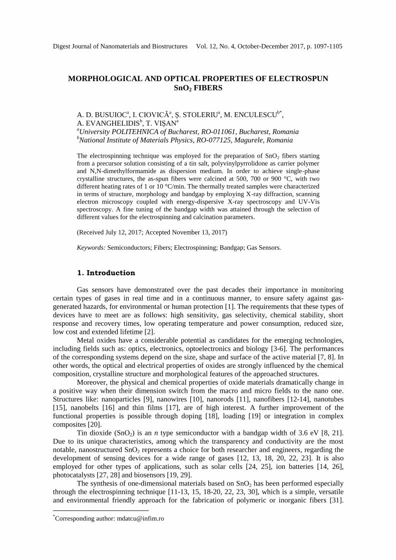
The precursor fibers containing both the mineral and organic components were subjected
to thermal analysis from room temperature to 1000 °C, in air. As it can be identified on the TG
curve (Fig. 1), the material suffers a significant weight loss of about 57 % up to 450 °C. Namely,
below 110 °C, a small weight loss associated with an endothermic effect is present, the process
being identified as the evaporation of residual solvent and moisture. Further, two important weight
losses with maxima at approximately 300 and 418 °C, coupled with an intense and extensive
exothermic effect, can be assigned to PVP combustion and chlorine elimination, simultaneously
with Sn2+
oxidation and SnO2 crystallization. At higher temperatures, a better arrangement of the
ions in the crystalline network is possible. The total weight loss in the studied range was calculated
as 69 %, the decrease occurred above 450 °C being determined by the air flow in the equipment;
this trains a part of the loose and light mass from the measuring crucible. In conclusion, the
minimum temperature at which the as-spun fibers should be calcined in order to achieve oxide
structures is 500 °C, higher values influencing especially the structural features and grain
dimension.
Fig. 1. Thermal analysis performed on the as-spun fibers: TG - thermogravimetric
analysis, DrTGA - the derivative of the themogravimetric analysis with respect to time and
DTA - differential thermal analysis
Going to the morphology of the precursor fibers, Figs. 2 a and a' display their overall
aspect, as well as the thickness and length. The resulted one-dimensional structures are deposited
on the substrate randomly, in the form of a nonwoven mesh, and present an uniform thickness over
the entire length. Based on the analysis of several SEM images, the average thickness was
estimated to about 400 nm, while the length can reach even hundreds of nm.
The EDX spectra recorded on both as-spun and 500 °C calcined samples (Fig. 2 b) show
the elemental composition and its evolution after the applied thermal treatment. It is obvious that
Cl- is completely removed from the system even for the lowest calcination temperature. C is still
present in the case of the thermally treated fibers due to the tape employed for fixing the
specimens, while Au was used as conductive coating.
1100
Fig. 2. SEM images of the as-spun fibers (a and a') and EDX spectra of
the fibers before and after calcination at 500 °C (b).
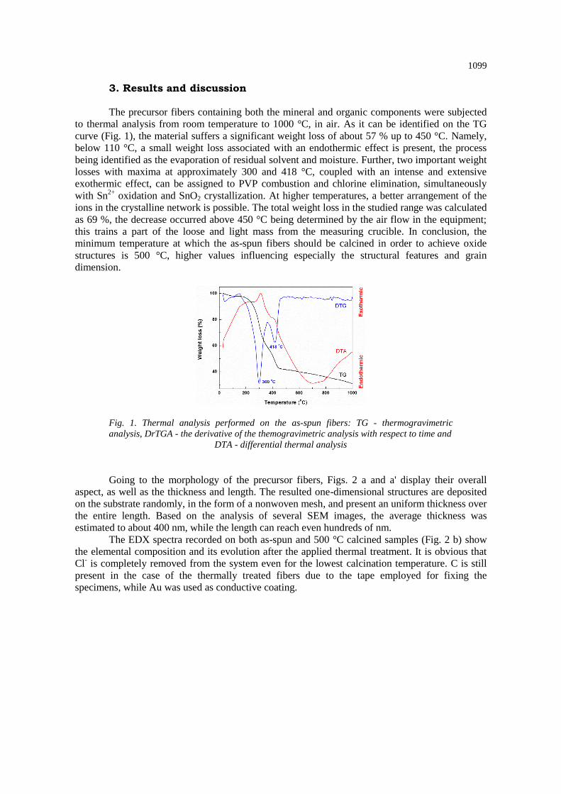
The thermal process allowed the obtaining of SnO2 with rutile-like structure (tetragonal
symmetry, JCPDS 01-080-6727) as single-phase. As indicated in Fig. 3, the emerged maxima are
attributed either to the deposited material or to the substrate. The growth of the calcination
temperature led, as expected, to the increase of the crystallinity degree, as well as to larger
crystallites, fact proved by the narrower and more intense peaks. A quick assessment of the
average crystallite size with Scherrer equation revealed a doubling of this parameter from 500 to
900 °C.
Fig. 3. XRD patterns of SnO2 calcined fibers for 1 °C/ min heating rate.
Figs. 4 and 5 present the SEM images at two magnifications for SnO2 fibers thermally
treated in different conditions. For all samples, a reduction of about 25 % in diameter can be
noticed, explained on the basis of organic part combustion, while the dimensional uniformity is
maintained. The processes of nucleation, growth and densification of the oxide phase are governed
by different laws, as a function of calcination temperature and heating rate. For 1 °C/min (Fig. 4),
the fibers are made up of quasi-spherical grains, whose average size increases with temperature
increasing from less than 20 nm (500 °C - Figs. 4 a and a') to approximately 40 nm (700 °C - Figs.
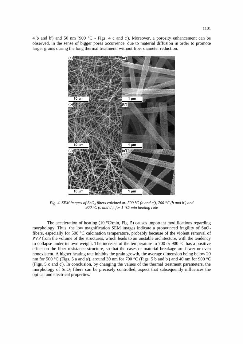
1101
4 b and b') and 50 nm (900 °C - Figs. 4 c and c'). Moreover, a porosity enhancement can be
observed, in the sense of bigger pores occurrence, due to material diffusion in order to promote
larger grains during the long thermal treatment, without fiber diameter reduction.
Fig. 4. SEM images of SnO2 fibers calcined at: 500 °C (a and a'), 700 °C (b and b') and
900 °C (c and c'), for 1 °C/ min heating rate
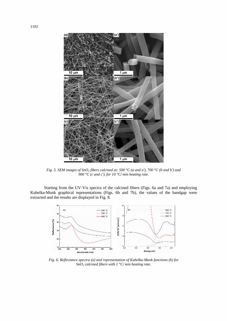
The acceleration of heating (10 °C/min, Fig. 5) causes important modifications regarding
morphology. Thus, the low magnification SEM images indicate a pronounced fragility of SnO2
fibers, especially for 500 °C calcination temperature, probably because of the violent removal of
PVP from the volume of the structures, which leads to an unstable architecture, with the tendency
to collapse under its own weight. The increase of the temperature to 700 or 900 °C has a positive
effect on the fiber resistance structure, so that the cases of material breakage are fewer or even
nonexistent. A higher heating rate inhibits the grain growth, the average dimension being below 20
nm for 500 °C (Figs. 5 a and a'), around 30 nm for 700 °C (Figs. 5 b and b') and 40 nm for 900 °C
(Figs. 5 c and c'). In conclusion, by changing the values of the thermal treatment parameters, the
morphology of SnO2 fibers can be precisely controlled, aspect that subsequently influences the
optical and electrical properties.
1102
Fig. 5. SEM images of SnO2 fibers calcined at: 500 °C (a and a'), 700 °C (b and b') and
900 °C (c and c'), for 10 °C/ min heating rate.
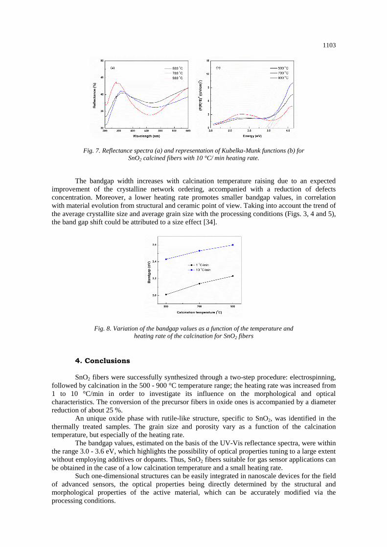
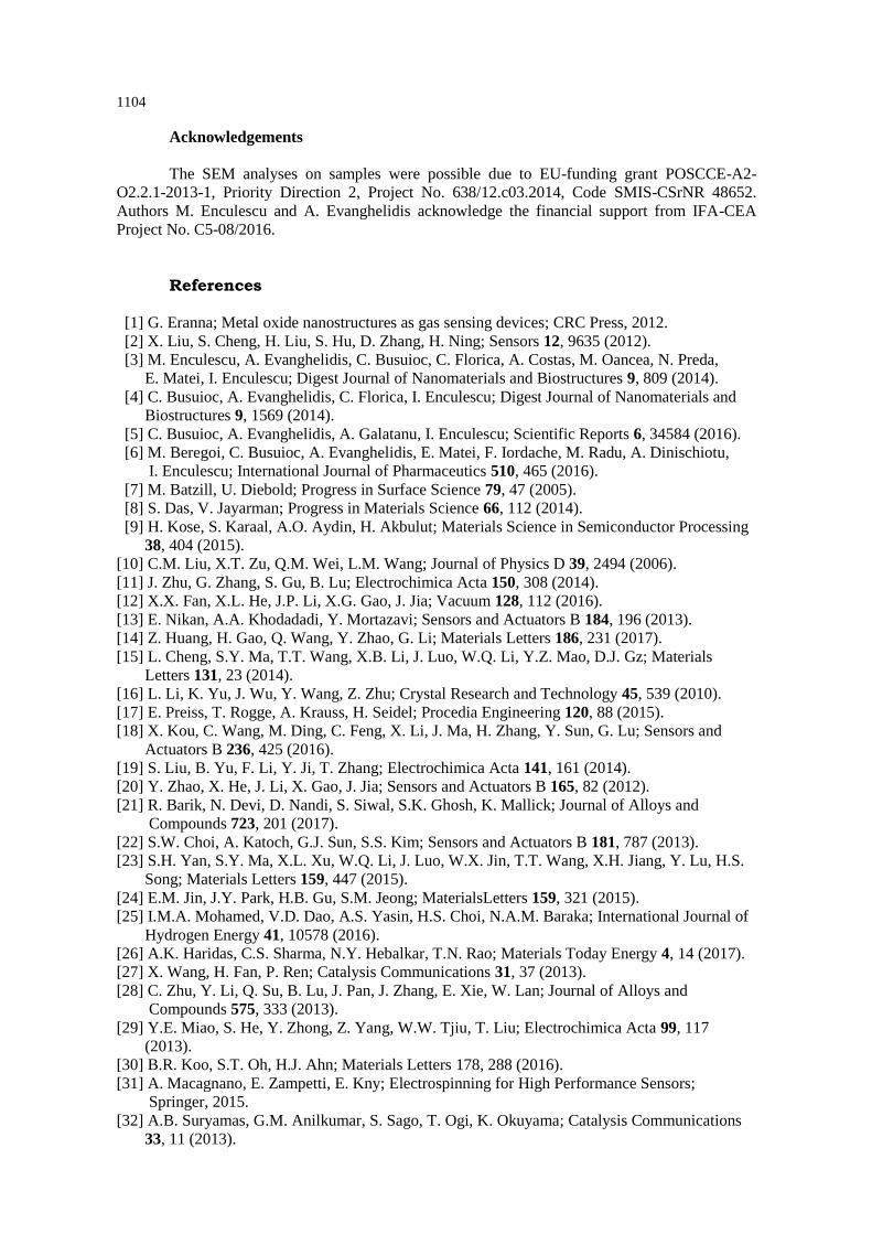
Starting from the UV-Vis spectra of the calcined fibers (Figs. 6a and 7a) and employing
Kubelka-Munk graphical representations (Figs. 6b and 7b), the values of the bandgap were
extracted and the results are displayed in Fig. 8.
Fig. 6. Reflectance spectra (a) and representation of Kubelka-Munk functions (b) for
SnO2 calcined fibers with 1 °C/ min heating rate.
1103
Fig. 7. Reflectance spectra (a) and representation of Kubelka-Munk functions (b) for
SnO2 calcined fibers with 10 °C/ min heating rate.
The bandgap width increases with calcination temperature raising due to an expected
improvement of the crystalline network ordering, accompanied with a reduction of defects
concentration. Moreover, a lower heating rate promotes smaller bandgap values, in correlation
with material evolution from structural and ceramic point of view. Taking into account the trend of
the average crystallite size and average grain size with the processing conditions (Figs. 3, 4 and 5),
the band gap shift could be attributed to a size effect [34].
Fig. 8. Variation of the bandgap values as a function of the temperature and
heating rate of the calcination for SnO2 fibers
4. Conclusions
SnO2 fibers were successfully synthesized through a two-step procedure: electrospinning,
followed by calcination in the 500 - 900 °C temperature range; the heating rate was increased from
1 to 10 °C/min in order to investigate its influence on the morphological and optical
characteristics. The conversion of the precursor fibers in oxide ones is accompanied by a diameter
reduction of about 25 %.
An unique oxide phase with rutile-like structure, specific to SnO2, was identified in the
thermally treated samples. The grain size and porosity vary as a function of the calcination
temperature, but especially of the heating rate.
The bandgap values, estimated on the basis of the UV-Vis reflectance spectra, were within
the range 3.0 - 3.6 eV, which highlights the possibility of optical properties tuning to a large extent
without employing additives or dopants. Thus, SnO2 fibers suitable for gas sensor applications can
be obtained in the case of a low calcination temperature and a small heating rate.
Such one-dimensional structures can be easily integrated in nanoscale devices for the field
of advanced sensors, the optical properties being directly determined by the structural and
morphological properties of the active material, which can be accurately modified via the
processing conditions.
1104
Acknowledgements
The SEM analyses on samples were possible due to EU-funding grant POSCCE-A2-
O2.2.1-2013-1, Priority Direction 2, Project No. 638/12.c03.2014, Code SMIS-CSrNR 48652.
Authors M. Enculescu and A. Evanghelidis acknowledge the financial support from IFA-CEA
Project No. C5-08/2016.
References
[1] G. Eranna; Metal oxide nanostructures as gas sensing devices; CRC Press, 2012.
[2] X. Liu, S. Cheng, H. Liu, S. Hu, D. Zhang, H. Ning; Sensors 12, 9635 (2012).
[3] M. Enculescu, A. Evanghelidis, C. Busuioc, C. Florica, A. Costas, M. Oancea, N. Preda,
E. Matei, I. Enculescu; Digest Journal of Nanomaterials and Biostructures 9, 809 (2014).
[4] C. Busuioc, A. Evanghelidis, C. Florica, I. Enculescu; Digest Journal of Nanomaterials and
Biostructures 9, 1569 (2014).
[5] C. Busuioc, A. Evanghelidis, A. Galatanu, I. Enculescu; Scientific Reports 6, 34584 (2016).
[6] M. Beregoi, C. Busuioc, A. Evanghelidis, E. Matei, F. Iordache, M. Radu, A. Dinischiotu,
I. Enculescu; International Journal of Pharmaceutics 510, 465 (2016).
[7] M. Batzill, U. Diebold; Progress in Surface Science 79, 47 (2005).
[8] S. Das, V. Jayarman; Progress in Materials Science 66, 112 (2014).
[9] H. Kose, S. Karaal, A.O. Aydin, H. Akbulut; Materials Science in Semiconductor Processing
38, 404 (2015).
[10] C.M. Liu, X.T. Zu, Q.M. Wei, L.M. Wang; Journal of Physics D 39, 2494 (2006).
[11] J. Zhu, G. Zhang, S. Gu, B. Lu; Electrochimica Acta 150, 308 (2014).
[12] X.X. Fan, X.L. He, J.P. Li, X.G. Gao, J. Jia; Vacuum 128, 112 (2016).
[13] E. Nikan, A.A. Khodadadi, Y. Mortazavi; Sensors and Actuators B 184, 196 (2013).
[14] Z. Huang, H. Gao, Q. Wang, Y. Zhao, G. Li; Materials Letters 186, 231 (2017).
[15] L. Cheng, S.Y. Ma, T.T. Wang, X.B. Li, J. Luo, W.Q. Li, Y.Z. Mao, D.J. Gz; Materials
Letters 131, 23 (2014).
[16] L. Li, K. Yu, J. Wu, Y. Wang, Z. Zhu; Crystal Research and Technology 45, 539 (2010).
[17] E. Preiss, T. Rogge, A. Krauss, H. Seidel; Procedia Engineering 120, 88 (2015).
[18] X. Kou, C. Wang, M. Ding, C. Feng, X. Li, J. Ma, H. Zhang, Y. Sun, G. Lu; Sensors and
Actuators B 236, 425 (2016).
[19] S. Liu, B. Yu, F. Li, Y. Ji, T. Zhang; Electrochimica Acta 141, 161 (2014).
[20] Y. Zhao, X. He, J. Li, X. Gao, J. Jia; Sensors and Actuators B 165, 82 (2012).
[21] R. Barik, N. Devi, D. Nandi, S. Siwal, S.K. Ghosh, K. Mallick; Journal of Alloys and
Compounds 723, 201 (2017).
[22] S.W. Choi, A. Katoch, G.J. Sun, S.S. Kim; Sensors and Actuators B 181, 787 (2013).
[23] S.H. Yan, S.Y. Ma, X.L. Xu, W.Q. Li, J. Luo, W.X. Jin, T.T. Wang, X.H. Jiang, Y. Lu, H.S.
Song; Materials Letters 159, 447 (2015).
[24] E.M. Jin, J.Y. Park, H.B. Gu, S.M. Jeong; MaterialsLetters 159, 321 (2015).
[25] I.M.A. Mohamed, V.D. Dao, A.S. Yasin, H.S. Choi, N.A.M. Baraka; International Journal of
Hydrogen Energy 41, 10578 (2016).
[26] A.K. Haridas, C.S. Sharma, N.Y. Hebalkar, T.N. Rao; Materials Today Energy 4, 14 (2017).
[27] X. Wang, H. Fan, P. Ren; Catalysis Communications 31, 37 (2013).
[28] C. Zhu, Y. Li, Q. Su, B. Lu, J. Pan, J. Zhang, E. Xie, W. Lan; Journal of Alloys and
Compounds 575, 333 (2013).
[29] Y.E. Miao, S. He, Y. Zhong, Z. Yang, W.W. Tjiu, T. Liu; Electrochimica Acta 99, 117
(2013).
[30] B.R. Koo, S.T. Oh, H.J. Ahn; Materials Letters 178, 288 (2016).
[31] A. Macagnano, E. Zampetti, E. Kny; Electrospinning for High Performance Sensors;
Springer, 2015.
[32] A.B. Suryamas, G.M. Anilkumar, S. Sago, T. Ogi, K. Okuyama; Catalysis Communications
33, 11 (2013).

1105
[33] A. Katoch, J.H. Byun, S.W. Choi, S.S. Kim; Sensors and Actuators B 202, 38 (2014).
[34] C. Busuioc, A. Evanghelidis, M. Enculescu, I. Enculescu; Digest Journal of Nanomaterials
and Biostructures 10, 957 (2015).