mors smitt industrial technology industrial current ... en/brochure-industrial... · mors smitt...
TRANSCRIPT
H a l l e f f e c t c u r r e n t & v o l t a g e s e n s o r s
Mors Smitt Industrial Technology Industrial current & voltage sensors


Industrial current & voltage sensors
Mors Smitt Industrial Technology
Industrial sensors

Closed loop current & voltage sensors meeting
major standards

5
www.morssmitt.com
Mors Smitt Industrial Technology
Mors Smitt has extended its product portfolio focusing on market sectors like power generation, transmission and distribution, factory automation, petro-chemical, water treatment plants and gene-ral industrial requirements.
Industrial sensorsToday, more and more applications that used to be mechanical are changing to fully electronic control offering increased reliability, improved regulation standards and higher energy efficiency.
For motors with inverter control total energy consumed savings of up to 50% are achievable. The inverter control requires reliable, accurate current measurements.
For renewable sources, power electronics also play a key role in energy savings. Modern systems are becoming more complex and require precise coordination between the power semiconductors, the system controller, mechanics and the feedback sensors. The sensors provide all necessary information of the load to fulfill that function.
Other power electronics applications involving sensors are: motor drives, UPS, welding, robotics, cranes, cable cars, ski lifts, elevators, medical systems, power supplies for computer servers and telecom.
Mors Smitt closed loop sensors ensure high accuracy of current measuring in power electronics equipments for a full protection against overload or underload, control and regulation of the power equipment.
ReliabilityWorldwide availability is assured by a network of professional, trained and dedicated subsidiaries, distributors and agents, offering local service and support.
Mors Smitt offers customizable protection solutions, enhancing safety and performance. Not just our products and services but also our production sites are focused on environmental performance improvements by certification of the ISO 9001:2008 and ISO 14001 standards.
The company strategy for the future is based upon further responsible development and expansion of its high quality components, responding to tomorrow’s needs in the many current sectors it serves. It is based upon putting the skills and talents of its staff to work for company, clients and mankind. Keeping that part of the world’s operation for which it plays a role, working successfully, without question and without failure.
Mors Smitt is part of Wabtec Corporation, the NYSE stock exchange listed, global supplier of highly engineered components and solutions for rail and selected industrial markets. Operations in 17 countries and world wide sales in over 100 countries. Wabtec Corporation holds over 1.200 patents and has world class internal processes based on lean manufacturing and continuous improvement principles (Wabtec Performance System).
Within the Wabtec group Mors Smitt has its own name & identity and is focused on satisfying the needs of customers in the power grid, industry and installation sectors.
September 2015 Mors Smitt continuously improves its products and services. Specifications are changed without prior notice. No rights can be derived from specifications in this brochure. Changes and printed errors reserved.
6 www.morssmitt.com
Industrial sensors
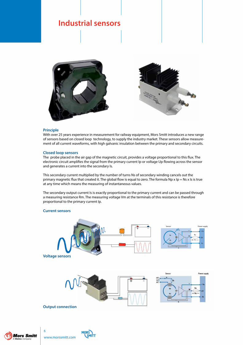
PrincipleWith over 25 years experience in measurement for railway equipment, Mors Smitt introduces a new range of sensors based on closed loop technology, to supply the industry market. These sensors allow measure-ment of all current waveforms, with high galvanic insulation between the primary and secondary circuits.
Closed loop sensorsThe probe placed in the air gap of the magnetic circuit, provides a voltage proportional to this flux. The electronic circuit amplifies the signal from the primary current Ip or voltage Up flowing across the sensor and generates a current into the secondary Is. This secondary current multiplied by the number of turns Ns of secondary winding cancels out the primary magnetic flux that created it. The global flow is equal to zero. The formula Np x Ip = Ns x Is is true at any time which means the measuring of instantaneous values.
The secondary output current Is is exactly proportional to the primary current and can be passed through a measuring resistance Rm. The measuring voltage Vm at the terminals of this resistance is therefore proportional to the primary current Ip.
Current sensors
Voltage sensors
Output connection
Power supply
+ VA
OV
- VA
RM
VM
+
M
-
NP
NS
IP
IS
Sensor

7
www.morssmitt.com
Molex output connector for MSA sensors M5 output connectors for MSV sensors
High galvanic isolationDielectric strength of 3.8 kV...6 kV - 50 Hz -1 min
Measuring of all waveformsDC, AC, impulse currents
Excellent accuracy, immunity and response timeFrom ± 1.5 % to ± 0.5 % at rated current over -40 °C...+85 °C with linearity < 0.1 %, and over a large frequency from DC to AC and impulse waveforms. Response time <1 µs
Form fit function The sensors can be mounted vertically or horizontally and provide form fit functions with other sensors
EMC compliantAll sensors include EMC compliancy
Compliant to major industrial standardsEN 50178 Electronic equipment for use in power installationsEN 61000-6-2 Electromagnetic compatibility - immunity for industrial environmentsEN 61000-6-4 Electromagnetic compatibility - emission standard for industial environments
Dedicated customer service & productionMors Smitt ensures customer support throughout the product life cycle, moreover we are able to adapt our capacity of production and reactivity to exceed our customer on time delivery and after sales service.
5 year warrantyMors Smitt return of experience in the railway sector facing the harshest environments and strictest standards allow us to provide our customers a 5 year warranty on all our industrial sensors.

8 www.morssmitt.com
Applications
Motor and renewable energy inverters
Typical applications:• Machine tools, printing, paper, textile, plastic• Steel mills• Lifts• Cranes• Robotics• Pumps• Energy inverters for all kind of renewable energies (wind, sun, hydrogen, ocean currents, energy storage etc.
G~
1~
3~ ~-
3~
3~
Uninterruptible power supplies
Typical applications:• EDP systems• Telecom• Security systems
3~
3~
Charger DC link VDC Battery Inverter I IDC
IL Rectifier or inverter DC link VDC PWM Inverter IM
IDC
~- ~
-
~- ~
-

9
www.morssmitt.com
1~
3~
Battery supplied applications
Typical applications:• Electric vehicles (zero emission vehicles)• Forklift trucks• Wheel chairs• Solar power supplies
M~
~-
Power supplies for welding applications
Typical applications:• Test & measurement in laboratories & universities• Medical X ray and imaging equipment• Electrolysis, currents monitoring• Inductive heating• Energy management systems, monitoring of load currents• Overcurrent protection• Control and safety systems• Electrical traction
AC
--
1~
3~
Input rectifier DC link VDC PWM Inverter Output rectifier I
IDC
DC
I
Charger IDC
Battery Inverter IM
3~
~-
~- -
-
~-
10 www.morssmitt.com
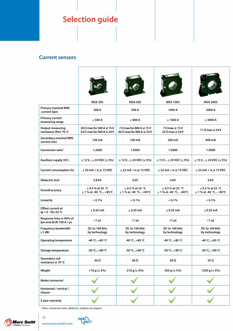
MSA 305 MSA 505 MSA 1005 MSA 2005
Primary nominal RMS current (lpn) 300 A 500 A 1000 A 2000 A
Primary current measuring range + 500 A + 800 A + 1500 A + 3000 A
Output measuring resistance (Rm) 70 oC
20 Ω max for 500 A @ 15 V54 Ω max for 500 A @ 24 V
7 Ω max for 800 A @ 15 V60 Ω max for 800 A @ 24 V
7 Ω max @ 15 V 25 Ω max @ 24 V 11 Ω max @ 24 V
Secondary nominal RMS current (Isn) 150 mA 100 mA 200 mA 400 mA
Conversion ratio1 1:2000 1:5000 1:5000 1:5000
Auxiliary supply (VC) + 12 V... + 24 VDC (+ 5%) + 12 V... + 24 VDC (+ 5%) + 15 V... + 24 VDC (+ 5%) + 15 V... + 24 VDC (+ 5%)
Current consumption (Ic) + 20 mA + Is @ 15 VDC + 22 mA + Is @ 15 VDC + 22 mA + Is @ 15 VDC + 33 mA + Is @ 15 VDC
Dielectric test1 3.8 kV 4 kV 4 kV 6 kV
Overall acuracy + 0.5 % at 25 oC+ 1 % at -40 oC... +85oC
+ 0.5 % at 25 oC+ 1 % at -40 oC... +85oC
+ 0.5 % at 25 oC+ 1 % at -40 oC... +85oC
+ 0.5 % at 25 oC+ 1 % at -40 oC... +85oC
Linearity < 0.1% < 0.1% < 0.1% < 0.1%
Offset current at lp = 0 - TA=25 oC + 0.25 mA + 0.25 mA + 0.25 mA + 0.25 mA
Response time @ 90% of lpn and di/dt 100 A / µs <1 µs <1 µs <1 µs <1 µs
Frequency bandwidth (-1 dB)
DC to 100 kHz by technology
DC to 100 kHzby technology
DC to 100 kHzby technology
DC to 100 kHzby technology
Operating temperature -40 oC...+85 oC -40 oC...+85 oC -40 oC...+85 oC -40 oC...+85 oC
Storage temperature -50 oC...+90 oC -50 oC...+90 oC -50 oC...+90 oC -50 oC...+90 oC
Secondary coil resistance @ 70 oC 30 Ω 60 Ω 30 Ω 25 Ω
Weight 110 g (+ 5%) 210 g (+ 5%) 550 g (+ 5%) 1550 g (+ 5%)
Molex connector1
Horizontal / vertical / chassis
5 year warranty
1 other conversion ratio, dielectric, outputs on request
Selection guide
Current sensors

11
www.morssmitt.com
MSV 100 MSV 200
Primary nominal RMSvoltage (lpn) 950 V 1000 V 2000 V 3000 V 4000 V 5000 V
Primary current measuring range + 1400 A + 1500 A + 3000 A + 4500 A + 6000 A + 6000 A
Output measuring resistance (Rm) 25 oC 220 Ω max for 1400 V tba
Secondary nominal RMS current (Isn) 50 mA for 1000 V 50 mA
Conversion ratio1 1000 V / 50 mA 1/5 1/10 1/15 1/20 1/25
Auxiliary supply (VC) + 12 V... + 24 VDC (+ 5%) + 12 V... + 24 VDC (+ 5%)
Current consumption (Ic) + 20 mA + Is @ 15 VDC + 33 mA + Is @ 24 VDC
Dielectric test1 3.8 kV 10 kV
Overall acuracy + 0.5 % at 25 oC+ 1 % at -40 oC... +85oC + 0.7 % at 25 oC
Linearity < 0.1% < 0.1%
Offset current at lp = 0 - TA=25 oC + 0.25 mA + 0.2 mA
Response time @ 90% of lpn and di/dt 100 A / µs <1 µs <100 µs
Frequency bandwidth (-1 dB)
DC to 100 kHzby technology DC to 100 kHz by technology
Operating temperature -50 oC...+85 oC -50 oC...+85 oC
Storage temperature -50 oC...+90 oC -50 oC...+90 oC
Secondary coil resistance @ 70 oC 60 Ω + 7% 60 Ω + 7%
Weight 500 g (+ 10%) 800 g (+ 10%)
Molex connector1
Horizontal / vertical / chassis
5 year warranty
1 other conversion ratio, dielectric, outputs on request
Voltage sensors

12 www.morssmitt.com
Current senors
General data• The housing and insulation resin (UL94 V0) are self-extinguishable upon fire• Mounting holes are provided in the housing mold for two positions on a base or flat mount through a plate • Direction of current: a primary current flowing in the direction of the top arrow on the sensor generates a positive secondary output current on terminal M
Primary connection• Hole for primary conductor• The temperature of the primary conductor in contact with the housing shall not exceed 100 °C
Secondary connection• Molex HE14 type connector• Other output on request
Wiring and mounting instructionsThese general instructions are not exhaustive and provide basis for proper installation of the sensors. Each configuration being different, please consult us for particular advice. (Note that non proper installation or incorrect use of the sensor can result in sensor poor performances or malfunction)
Wiring diagram• Direction of current: a primary current Ip flowing in the direction of the top arrow on the sensor generates a positive secondary output current on terminal M• Auxiliary supply voltage : bipolar voltage –VDC…0 V…+VDC
Features
+ + VDC
M 0 V
- - VDC
IS RM
VM
Current sensor Power supply

13
www.morssmitt.com
Mechanical mounting• Any mounting position is possible• Recommended fixing: by screws and flat washers• The busbar (or cable) must be centred
Precautions in electromagnetic environmentDue to their principle of operation (measure of magnetic field by the Hall effect probe), closed loop hall effect current sensors can be sensitive to strong magnetic fields. It is recommended to avoid positioning them to close to high current power cables.
Processing of the sensor output signalStandard codes of practice advise that, before the signal is processed, a low-pass filter adapted to the bandwidth of the sensor is used. Also, in the case of digital processing of the signal, it is also recommended that the sampling frequency is adapted to the bandwidth of both the signal to be measured and the sensor.
In the event of sensor failure, the processing of the output signal should take into account deterioration in performance (i.e. absence of signal or saturated signal) and rapidly and safely shut the system down.
Safety instructions
Our sensors must be used in electrical or electronic equipment with respect to relevant standards and safety requirements in accordance with the manufacturer’s operating instructions.
Caution, risk of electrical shock
When operating the sensor, certain parts of the module can carry hazardous voltage (eg. primary terminals, power supply). Ignoring this warning can lead to injury and/or cause serious damage. This sensor is a built-in device, whose conducting parts must be inaccessible after installation. A protective housing or additional shield could be used. Main supply must be able to be disconnected.
14 www.morssmitt.com
Current sensors
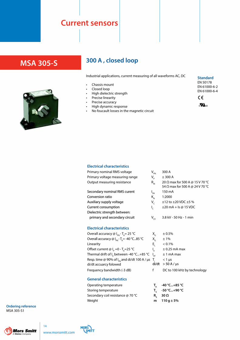
MSA 305-S
StandardEN 50178EN 61000-6-2EN 61000-6-4
Ordering referenceMSA 305-S1
300 A , closed loop
Industrial applications, current measuring of all waveforms AC, DC
• Chassis mount• Closed loop• High dielectric strength• Precise linearity• Precise accuracy• High dynamic response• No foucault losses in the magnetic circuit
Electrical characteristicsPrimary nominal RMS voltage VPN 300 APrimary voltage measuring range VP ± 300 AOutput measuring resistance RM 20 Ω max for 500 A @ 15 V 70 °C
54 Ω max for 500 A @ 24 V 70 °CSecondary nominal RMS curent ISN 150 mAConversion ratio KN 1:2000Auxiliary supply voltage VC ±12 to ±20 VDC ±5 %Current consumption IC ±20 mA + Is @ 15 VDCDielectric strength between: primary and secondary circuit VD1 3.8 kV - 50 Hz - 1 min
Electrical characteristicsOverall accuracy @ IPN - TA= 25 °C XG ± 0.5%Overall accuracy @ IPN - TA= -40 °C...85 °C XG ± 1%Linearity EL < 0.1%Offset current @ IP =0 - TA=25 °C I0 ± 0.25 mA maxThermal drift of I0 between -40 °C...+85 °C I0T ± 1 mA maxResp. time @ 90% of IPN and di/dt 100 A / µsdi/dt accuarcy folowed
Trdi/dt
< 1 µs> 50 A / µs
Frequency bandwidth (-3 dB) f DC to 100 kHz by technology
General characteristicsOperating temperature TA -40 °C...+85 °CStoring temperature TS -50 °C...+90 °CSecondary coil resistance @ 70 °C RS 30 Ω Weight m 110 g ± 5%

15
www.morssmitt.com
Connections
Dimensions
M -
+ Is Rm
+Vdc0v-Vdc
MSA 305
+ VDC
0 V
- VDC

16 www.morssmitt.com
Current sensors
MSA 505-S
StandardEN 50178EN 61000-6-2EN 61000-6-4
Ordering referenceMSA 505-S1
500 A , closed loop
Industrial applications, current measuring of all waveforms AC, DC
• Chassis mount• Closed loop• High dielectric strength• Precise linearity• Precise accuracy• High dynamic response• No foucault losses in the magnetic circuit
Electrical characteristicsPrimary nominal RMS voltage VPN 500 APrimary voltage measuring range VP ± 800 AOutput measuring resistance RM 7 Ω max for 800 A @ 15 V 70 °C
60 Ω max for 800 A @ 24 V 70 °CSecondary nominal RMS curent ISN 100 mAConversion ratio KN 1:5000Auxiliary supply voltage VC ±12 to ±24 VDC ±5 %Current consumption IC ± 22 mA + Is @ 15 VDCDielectric strength between: primary and secondary circuit VD1 4 kV - 50 Hz - 1 min
Electrical characteristicsOverall accuracy @ IPN - TA= 25 °C XG ± 0.5%Overall accuracy @ IPN - TA= -40 °C...85 °C XG ± 1%Linearity EL < 0.1%Offset current @ IP =0 - TA=25 °C I0 ± 0.25 mA maxThermal drift of I0 between -40 °C...+85 °C I0T ± 1 mA maxResp. time @ 90% of IPN and di/dt 100 A / µsdi/dt accuarcy folowed
Trdi/dt
< 1 µs> 100 A / µs
Frequency bandwidth (-3 dB) f DC to 100 kHz by technology
General characteristicsOperating temperature TA -40 °C...+85 °CStoring temperature TS -50 °C...+90 °CSecondary coil resistance @ 70 °C RS 60 Ω Weight m 210 g ± 5%

17
www.morssmitt.com
Connections
Dimensions
M -
+ Is Rm
+Vdc0v-Vdc
MSA 505
+ VDC
0 V
- VDC
18 www.morssmitt.com
Current sensors
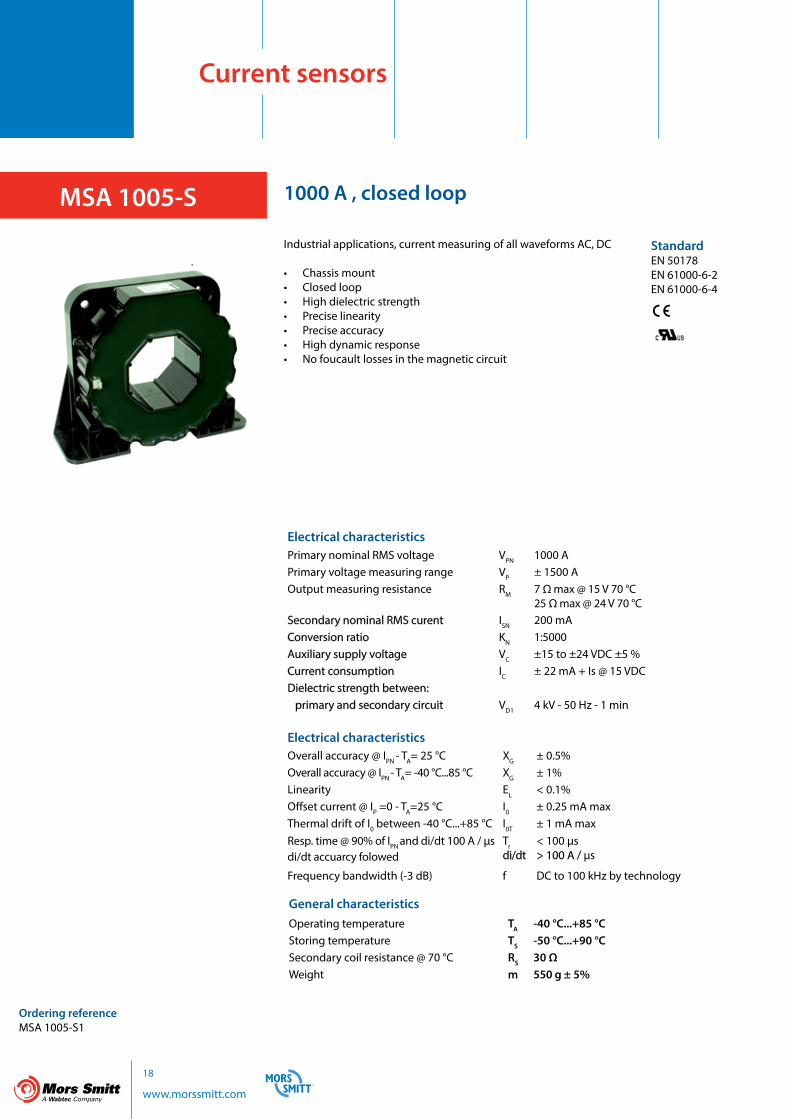
MSA 1005-S
StandardEN 50178EN 61000-6-2EN 61000-6-4
Ordering referenceMSA 1005-S1
1000 A , closed loop
Industrial applications, current measuring of all waveforms AC, DC
• Chassis mount• Closed loop• High dielectric strength• Precise linearity• Precise accuracy• High dynamic response• No foucault losses in the magnetic circuit
Electrical characteristicsPrimary nominal RMS voltage VPN 1000 APrimary voltage measuring range VP ± 1500 AOutput measuring resistance RM 7 Ω max @ 15 V 70 °C
25 Ω max @ 24 V 70 °CSecondary nominal RMS curent ISN 200 mAConversion ratio KN 1:5000Auxiliary supply voltage VC ±15 to ±24 VDC ±5 %Current consumption IC ± 22 mA + Is @ 15 VDCDielectric strength between: primary and secondary circuit VD1 4 kV - 50 Hz - 1 min
Electrical characteristicsOverall accuracy @ IPN - TA= 25 °C XG ± 0.5%Overall accuracy @ IPN - TA= -40 °C...85 °C XG ± 1%Linearity EL < 0.1%Offset current @ IP =0 - TA=25 °C I0 ± 0.25 mA maxThermal drift of I0 between -40 °C...+85 °C I0T ± 1 mA maxResp. time @ 90% of IPN and di/dt 100 A / µsdi/dt accuarcy folowed
Trdi/dt
< 100 µs> 100 A / µs
Frequency bandwidth (-3 dB) f DC to 100 kHz by technology
General characteristicsOperating temperature TA -40 °C...+85 °CStoring temperature TS -50 °C...+90 °CSecondary coil resistance @ 70 °C RS 30 Ω Weight m 550 g ± 5%

19
www.morssmitt.com
Connections
Dimensions
M -
+ Is Rm
+Vdc0v-Vdc
MSA 1005
+ VDC
0 V
- VDC
20 www.morssmitt.com
Current sensors
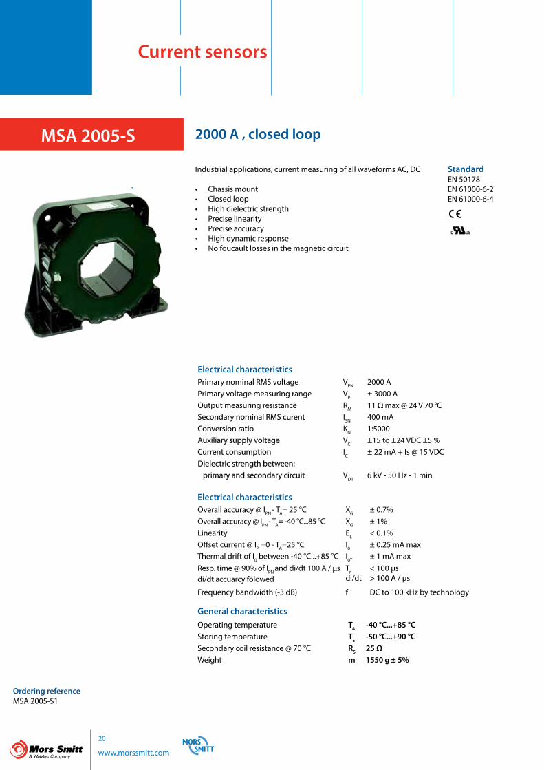
MSA 2005-S
StandardEN 50178EN 61000-6-2EN 61000-6-4
Ordering referenceMSA 2005-S1
2000 A , closed loop
Industrial applications, current measuring of all waveforms AC, DC
• Chassis mount• Closed loop• High dielectric strength• Precise linearity• Precise accuracy• High dynamic response• No foucault losses in the magnetic circuit
Electrical characteristicsPrimary nominal RMS voltage VPN 2000 APrimary voltage measuring range VP ± 3000 AOutput measuring resistance RM 11 Ω max @ 24 V 70 °CSecondary nominal RMS curent ISN 400 mAConversion ratio KN 1:5000Auxiliary supply voltage VC ±15 to ±24 VDC ±5 %Current consumption IC ± 22 mA + Is @ 15 VDCDielectric strength between: primary and secondary circuit VD1 6 kV - 50 Hz - 1 min
Electrical characteristicsOverall accuracy @ IPN - TA= 25 °C XG ± 0.7%Overall accuracy @ IPN - TA= -40 °C...85 °C XG ± 1%Linearity EL < 0.1%Offset current @ IP =0 - TA=25 °C I0 ± 0.25 mA maxThermal drift of I0 between -40 °C...+85 °C I0T ± 1 mA maxResp. time @ 90% of IPN and di/dt 100 A / µsdi/dt accuarcy folowed
Trdi/dt
< 100 µs> 100 A / µs
Frequency bandwidth (-3 dB) f DC to 100 kHz by technology
General characteristicsOperating temperature TA -40 °C...+85 °CStoring temperature TS -50 °C...+90 °CSecondary coil resistance @ 70 °C RS 25 Ω Weight m 1550 g ± 5%

21
www.morssmitt.com
Connections
Dimensions
M -
+ Is Rm
+Vdc0v-Vdc
MSA 2005
+ VDC
0 V
- VDC
22 www.morssmitt.com
Voltage sensors
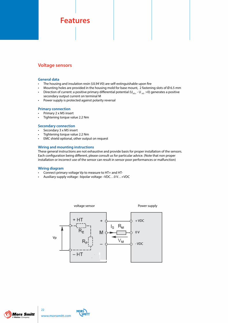
General data• The housing and insulation resin (UL94 V0) are self-extinguishable upon fire• Mounting holes are provided in the housing mold for base mount, 2 fastening slots of Ø 6.5 mm• Direction of current: a positive primary differential potential (UHT+ - U HT- >0) generates a positive secondary output current on terminal M• Power supply is protected against polarity reversal
Primary connection• Primary 2 x M5 insert• Tightening torque value 2.2 Nm
Secondary connection• Secondary 3 x M5 insert• Tightening torque value 2.2 Nm• EMC shield optional, other output on request
Wiring and mounting instructionsThese general instructions are not exhaustive and provide basis for proper installation of the sensors. Each configuration being different, please consult us for particular advice. (Note that non proper installation or incorrect use of the sensor can result in sensor poor performances or malfunction)
Wiring diagram• Connect primary voltage Vp to measure to HT+ and HT-• Auxiliary supply voltage : bipolar voltage –VDC…0 V…+VDC
Features
voltage sensor Power supply
Vp
+ VDC
0 V
- VDC

23
www.morssmitt.com
Mechanical mounting• Base mounting, heatsink on the top or on the side, with fins in vertical position• Recommended fixing: by 2 x M6 screws with flat washers • M5 inserts with tightening torque 2.2 Nm for primary and secondary connections
Precautions in electromagnetic environmentDue to their principle of operation (measure of magnetic field by the Hall effect probe), closed loop hall effect current sensors can be sensitive to strong magnetic fields. It is recommended to avoid positioning them to close to high current power cables.
Processing of the sensor output signalStandard codes of practice advise that, before the signal is processed, a low-pass filter adapted to the bandwidth of the sensor is used. Also, in the case of digital processing of the signal, it is also recommended that the sampling frequency is adapted to the bandwidth of both the signal to be measured and the sensor.
In the event of sensor failure, the processing of the output signal should take into account deterioration in performance (i.e. absence of signal or saturated signal) and rapidly and safely shut the system down.
Safety instructions
Our sensors must be used in electrical or electronic equipment with respect to relevant standards and safety requirements in accordance with the manufacturer’s operating instructions.
Caution, risk of electrical shock
When operating the sensor, certain parts of the module can carry hazardous voltage (eg. primary terminals, power supply). Ignoring this warning can lead to injury and/or cause serious damage. This sensor is a built-in device, whose conducting parts must be inaccessible after installation. A protective housing or additional shield could be used. Main supply must be able to be disconnected.
24 www.morssmitt.com
Voltage sensors
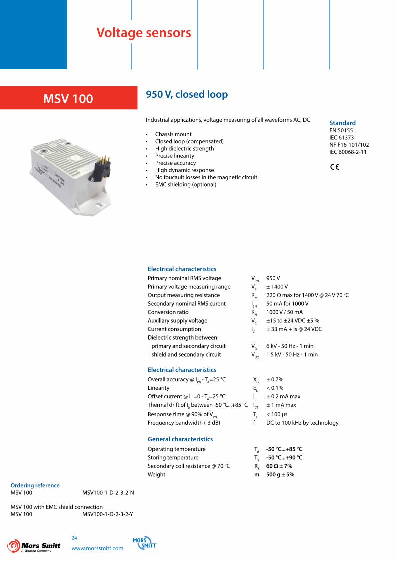
MSV 100
StandardEN 50155IEC 61373NF F16-101/102IEC 60068-2-11
Ordering referenceMSV 100 MSV100-1-D-2-3-2-N
MSV 100 with EMC shield connection MSV 100 MSV100-1-D-2-3-2-Y
950 V, closed loop
Industrial applications, voltage measuring of all waveforms AC, DC
• Chassis mount• Closed loop (compensated)• High dielectric strength• Precise linearity• Precise accuracy• High dynamic response• No foucault losses in the magnetic circuit• EMC shielding (optional)
Electrical characteristicsPrimary nominal RMS voltage VPN 950 VPrimary voltage measuring range VP ± 1400 V Output measuring resistance RM 220 Ω max for 1400 V @ 24 V 70 °CSecondary nominal RMS curent ISN 50 mA for 1000 VConversion ratio KN 1000 V / 50 mAAuxiliary supply voltage VC ±15 to ±24 VDC ±5 %Current consumption IC ± 33 mA + Is @ 24 VDCDielectric strength between: primary and secondary circuit VD1 6 kV - 50 Hz - 1 min shield and secondary circuit VD2 1.5 kV - 50 Hz - 1 min
Electrical characteristicsOverall accuracy @ IPN - TA=25 °C XG ± 0.7%Linearity EL < 0.1%Offset current @ IP =0 - TA=25 °C I0 ± 0.2 mA maxThermal drift of I0 between -50 °C...+85 °C I0T ± 1 mA max
Response time @ 90% of VPN Tr < 100 µsFrequency bandwidth (-3 dB) f DC to 100 kHz by technology
General characteristicsOperating temperature TA -50 °C...+85 °CStoring temperature TS -50 °C...+90 °CSecondary coil resistance @ 70 °C RS 60 Ω ± 7%Weight m 500 g ± 5%

25
www.morssmitt.com
Electrical characteristicsPrimary nominal RMS voltage VPN 950 VPrimary voltage measuring range VP ± 1400 V Output measuring resistance RM 220 Ω max for 1400 V @ 24 V 70 °CSecondary nominal RMS curent ISN 50 mA for 1000 VConversion ratio KN 1000 V / 50 mAAuxiliary supply voltage VC ±15 to ±24 VDC ±5 %Current consumption IC ± 33 mA + Is @ 24 VDCDielectric strength between: primary and secondary circuit VD1 6 kV - 50 Hz - 1 min shield and secondary circuit VD2 1.5 kV - 50 Hz - 1 min
Electrical characteristicsOverall accuracy @ IPN - TA=25 °C XG ± 0.7%Linearity EL < 0.1%Offset current @ IP =0 - TA=25 °C I0 ± 0.2 mA maxThermal drift of I0 between -50 °C...+85 °C I0T ± 1 mA max
Response time @ 90% of VPN Tr < 100 µsFrequency bandwidth (-3 dB) f DC to 100 kHz by technology
General characteristicsOperating temperature TA -50 °C...+85 °CStoring temperature TS -50 °C...+90 °CSecondary coil resistance @ 70 °C RS 60 Ω ± 7%Weight m 500 g ± 5%
Connections
Dimensions
MSV 100
(EMC shield is an option available with M5 secondary connection. EMC shield to be connected to ground or 0 V or -VDC)
_
+
MIs
+VDC
0 V- VDC
Rm
+HT
- HT
-VDC/0 V
E

26 www.morssmitt.com
Voltage sensors
MSV 200
StandardEN 50155IEC 61373NF F16-101/102IEC 60068-2-11
Ordering referenceMSV 200-1000V MSV200-1-D-2-3-2-NMSV 200-2000V MSV200-2-D-2-3-2-NMSV 200-3000V MSV200-3-D-2-3-2-NMSV 200-4000V MSV200-4-D-2-3-2-NMSV 200-5000V MSV200-5-D-2-3-2-N
MSV 200 with EMC shield connection MSV 200-1000V MSV200-1-D-2-3-2-YMSV 200-2000V MSV200-2-D-2-3-2-YMSV 200-3000V MSV200-3-D-2-3-2-YMSV 200-4000V MSV200-4-D-2-3-2-YMSV 200-5000V MSV200-5-D-2-3-2-Y
1000 V / 2000 V / 3000 V / 4000 V / 5000 V, closed loopIndustrial applications, voltage measuring of all waveforms AC, DC
• Chassis mount• Closed loop (compensated)• High dielectric strength• Precise linearity• Precise accuracy• High dynamic response• No foucault losses in the magnetic circuit• EMC shielding (optional)
Electrical characteristicsPrimary nominal RMS voltage VPN 1000 V / 2000 V / 3000 V / 4000 V / 5000 VPrimary voltage measuring range VP ± 1500 V / ± 3000 V / ± 4(00 V / ± 6000 VPrimary resistance @ 25 °C RP 100 kΩOutput measuring resistance RM tbaSecondary nominal RMS curent ISN 50 mA for 1000 VPrimary windings NP 10000 / 20000 / 30000 / 40000 / 50000Secondary windings NS 2000Conversion ratio KN NP / NS
Auxiliary supply voltage VC ±15 to ±24 VDC ±5 %Current consumption IC ±33 mA + Is @ 24 VDCDielectric strength between: primary and secondary circuit VD1 6 kV - 50 Hz - 1 min shield and secondary circuit VD2 1.5 kV - 50 Hz - 1 min
Electrical characteristicsOverall accuracy @ IPN - TA=25 °C XG ± 0.7%Linearity EL < 0.1%Offset current @ IP =0 - TA=25 °C I0 ± 0.2 mA maxThermal drift of I0 between -50 °C...+85 °C I0T ± 1 mA maxResponse time @ 90% of VPN Tr < 100 µsFrequency bandwidth (-3 dB) f DC to 100 kHz by technology
General characteristicsOperating temperature TA -50 °C...+85 °CStoring temperature TS -50 °C...+90 °CSecondary coil resistance @ 70 °C RS 60 Ω ± 7%Weight m 800 g ± 5%

27
www.morssmitt.com
Electrical characteristicsPrimary nominal RMS voltage VPN 1000 V / 2000 V / 3000 V / 4000 V / 5000 VPrimary voltage measuring range VP ± 1500 V / ± 3000 V / ± 4(00 V / ± 6000 VPrimary resistance @ 25 °C RP 100 kΩOutput measuring resistance RM tbaSecondary nominal RMS curent ISN 50 mA for 1000 VPrimary windings NP 10000 / 20000 / 30000 / 40000 / 50000Secondary windings NS 2000Conversion ratio KN NP / NS
Auxiliary supply voltage VC ±15 to ±24 VDC ±5 %Current consumption IC ±33 mA + Is @ 24 VDCDielectric strength between: primary and secondary circuit VD1 6 kV - 50 Hz - 1 min shield and secondary circuit VD2 1.5 kV - 50 Hz - 1 min
General characteristicsOperating temperature TA -50 °C...+85 °CStoring temperature TS -50 °C...+90 °CSecondary coil resistance @ 70 °C RS 60 Ω ± 7%Weight m 800 g ± 5%
MSV 200
(EMC shield is an option available with M5 secondary connection. EMC shield to be connected to ground or 0 V or -VDC)
_
+
MIs
+VDC
0 V
- VDC
Rm+HT
- HT
-VDC/0 V
E
Connections
Dimensions

28 www.morssmitt.com
Mors Smitt B.V.Vrieslantlaan 63526 AA UtrechtThe Netherlands
T +31 (0)30 288 1311F +31 (0)30 289 8816E [email protected]
Mors Smitt France SASTour Rosny 2Avenue du Général de Gaulle,F - 93118 Rosny-sous-BoisFrance
T +33 (0)1 4812 1440 F +33 (0)1 4855 9001E [email protected]
Mors Smitt Asia Ltd.# 807, Billion Trade Centre 31 Hung To RoadKwun Tong, KowloonHong Kong
T +852 2343 5555F +852 2343 6555E [email protected]
World wide sales network
29
www.morssmitt.com
Mors Smitt brochures are also available on our website: www.morssmitt.com
Surge protection devices
General purpose relaysHeavy duty relays
Instruments 1 Instruments 2
Actus relays
Industrial sensors
Nieaf-Smitt brochures are also available on our website: www.nieaf-smitt.com

Industrial current & voltage sensors
Mors Smitt Industrial Technology
Industrial sensors


SALES OFFICES
FRANCEMors Smitt France SASTour Rosny 2, Avenue du Général de Gaulle,F - 93118 Rosny-sous-Bois Cedex, FranceT +33 (0) 1 4812 1440F +33 (0) 1 4855 9001E [email protected]
HONG KONGMors Smitt Asia Ltd.29/F., Fun Tower, 35 Hung To RoadKwun Tong, Kowloon, Hong Kong SART +852 2343 5555F +852 2343 6555E [email protected]
THE NETHERLANDSMors Smitt B.V.Vrieslantlaan 63526 AA Utrecht, The NetherlandsT +31 (0)30 288 1311F +31 (0)30 289 8816E [email protected]
UNITED KINGDOMMors Smitt UK Ltd.Doulton Road, Cradley HeathWest Midlands, B64 5QB, UKT +44 (0)1384 567 755F +44 (0)1384 567 710E [email protected]
USAMors Smitt Technologies Inc.1010 Johnson DriveBuffalo Grove, IL 60089-6918, USAT +1 847 777 6497F +1 847 520 2222E [email protected]
Your local contact
www.morssmitt.com
BRO
Ind.
Sen
sors
V2.
3 Se
p 20
15