mos investigate avr & cbf relay
DESCRIPTION
MOS Investigate AVR & CBF RelayTRANSCRIPT
TNB 320/2013 TNBT 804913
T+ 9+
KERJA –KERJA ESTABLISHMENT OF PMU 275/33KV HULU TERENGGANU, TERENGGANU.
METHOD STATEMENT FOR:
Investigation on AVR Relay Faulty & Alarm for Breaker Failure Relay
CONTRACTOR
CD ELECTRICAL ENGINEERING SDN. BHD. – TRANSGRID VENTURES SDN. BHD. JOINT VENTURES
E-07-3, EAST WING BUSINESS PARK, SUBANG SQUARE, JALAN SS15/4G,
47050 SUBANG JAYA, SELANGOR D.E. TEL NO: 03-56219624 FAX NO: 03-56219752
Prepared by Check by Verified by Approved by
(ABDUL HADI MOHAMAD) CDEE-TGV JV
( ) Competent Engineer
( ) Engineer /Senior Engineer MP
( ) State Manager AM
TENAGA NASIONAL BERHAD

METHOD STATEMENT
CONTRACT NO.: TNB 320/2013 TENDER NO.: TNBT 804913
METHOD STATEMENT
Investigation on AVR Relay Faulty and Alarm for Breaker Failure Relay
Project Title : Kerja-kerja Establishment of PMU 275/33kV Hulu Terengganu, Terengganu
Substation : PMU 275/33kV Hulu Terengganu Bay : RTCC No.1 (EH+RT1)
275kV Bus Coupler (D04+R) Revision : 0 Date : 23-04-2015

METHOD STATEMENT
CLIENT: TENAGA NASIONAL BERHAD TENDER NO.: TNBT 804913
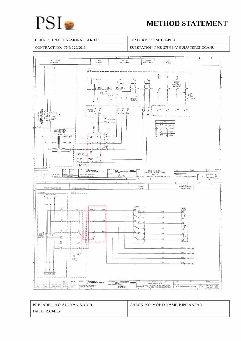
CONTRACT NO.: TNB 320/2013 SUBSTATION: PMU 275/33kV HULU TERENGGANU OBJECTIVES To investigate on the issues:
1. Siemens Microtapp AVR Relay at DH+RT1 (RTCC No 1) is not functioning well during paralleling with T2. In Auto Mode, when TPI is low, Raise command in AVR is malfunction
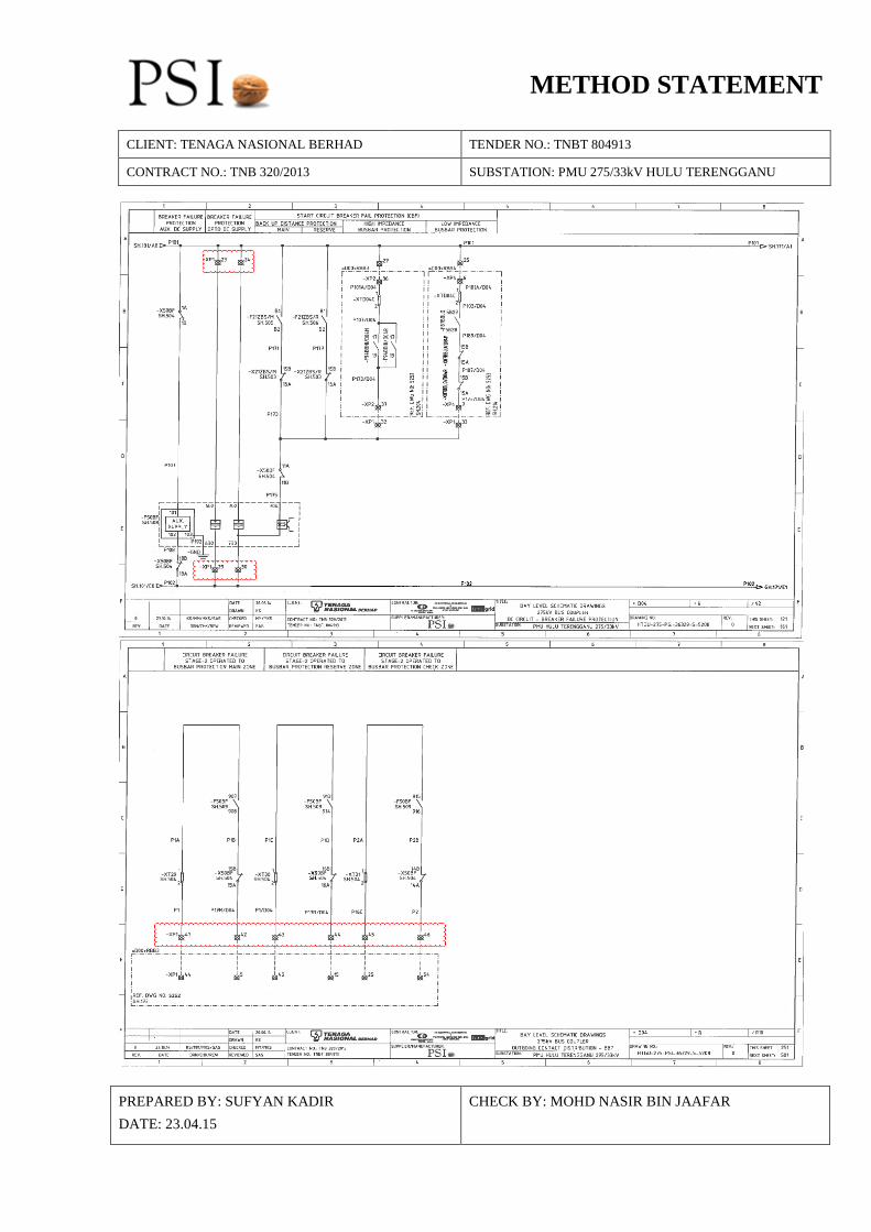
2. Alarm_Presist10 at Breaker Failure Relay (NARI RCS 921) for Bus Coupler bay D04+R occurred due to Neutral Current is higher than other phase
PANEL RELATED
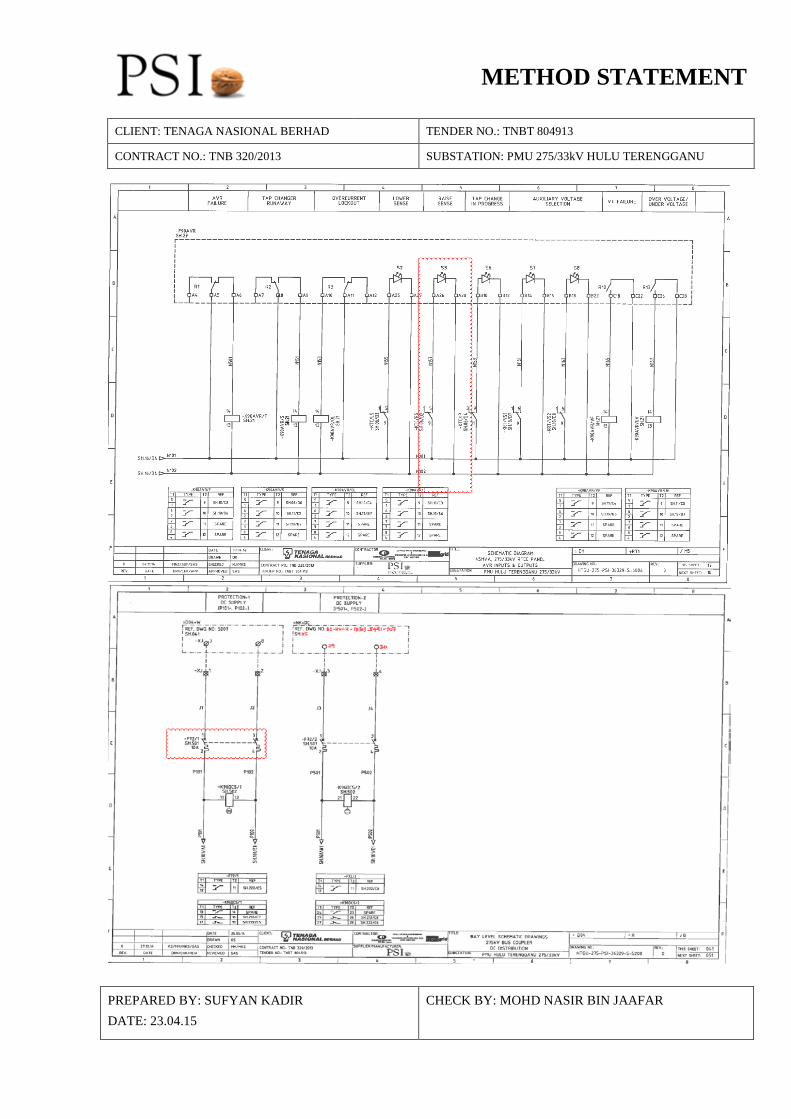
Based on the issues: 1. 275/33kV, 45MVA RTCC No 1 (DH+RT1) 2. 275kV Bus Coupler Relay Panel (D04+R)
STAFF LIST
Please refer to Appendix A. RISK ANALYSIS Please refer to Appendix B. WORK SCHEDULE Please refer to Appendix C. TOOLS Wiring tool, multimeter and drilling machine. ISOLATION AND TERMINATION LIST
Please refer to Appendix D. WORK PROCEDURE Please refer to Appendix D. CONTINGENCY PLAN Please refer to Appendix E. ITEM TO DISMANTLE AND INSTALL
No. Item To Dismantle Item To Install 1 Faulty AVR Relay
SIEMENS MICROTAPP New AVR Relay SIEMENS MICROTAPP
2 Faulty NARI RCS 921 Breaker Failure Relay New NARI RCS 921 Breaker Failure Relay Item dismantle are based on investigation, if the relay are faulty PSI will replace the faulty relay
PREPARED BY: SUFYAN KADIR DATE: 23.04.15
CHECK BY: MOHD NASIR BIN JAAFAR

METHOD STATEMENT
CLIENT: TENAGA NASIONAL BERHAD TENDER NO.: TNBT 804913
CONTRACT NO.: TNB 320/2013 SUBSTATION: PMU 275/33kV HULU TERENGGANU
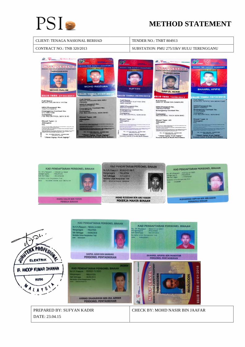
APPENDIX A STAFF LIST No. Name NRIC No. NIOSH No. NIOSH
Validity Date CIDB
Validity Date 1. Mohd Dalim Bin Yatim 730215-11-5329 TNB000885N 27/03/2017 05/03/2015
2. Mohd Ridzuan Bin Abu Hasan 900823-07-5913 TNB019618N 31/07/2015 05/11/2015
3. Muhammad Sufyan B Abd Kadir 900722-14-5003 TNB025993N 26/09/2016 76/06/2016
4. Saiful Azam Bin Samsuri 790102-14-5403 TNB001443N 14/ 08/2017 06/06/2016
5. Shahril Apipie Bin Mokhtar 900217-03-5997 TNB025993N 10/10/2016 06/05/2016
6. Ahmad Imaduddin Bin Zul Azman 850323-71-5053 TNB002026N 7/1/2018 6/5/2015
This is to certify that above listed personnel have been appointed to perform the site works such as dismantling works, panel cut out, wiring and termination works until cancellation of permit to work (PTW). The person above may vary depending on availability on the said work and day.
PREPARED BY: SUFYAN KADIR DATE: 23.04.15
CHECK BY: MOHD NASIR BIN JAAFAR
METHOD STATEMENT
CLIENT: TENAGA NASIONAL BERHAD TENDER NO.: TNBT 804913
CONTRACT NO.: TNB 320/2013 SUBSTATION: PMU 275/33kV HULU TERENGGANU
PREPARED BY: SUFYAN KADIR DATE: 23.04.15
CHECK BY: MOHD NASIR BIN JAAFAR
METHOD STATEMENT
CLIENT: TENAGA NASIONAL BERHAD TENDER NO.: TNBT 804913
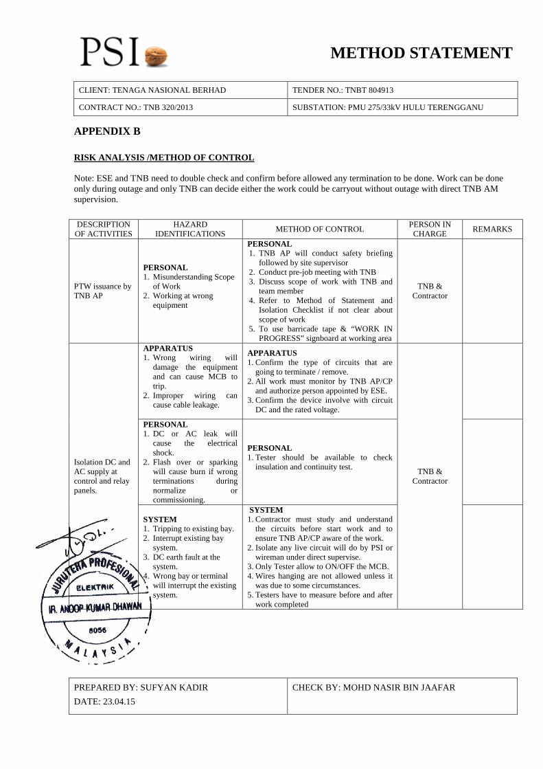
CONTRACT NO.: TNB 320/2013 SUBSTATION: PMU 275/33kV HULU TERENGGANU APPENDIX B RISK ANALYSIS /METHOD OF CONTROL Note: ESE and TNB need to double check and confirm before allowed any termination to be done. Work can be done only during outage and only TNB can decide either the work could be carryout without outage with direct TNB AM supervision. DESCRIPTION
OF ACTIVITIES HAZARD
IDENTIFICATIONS METHOD OF CONTROL PERSON IN CHARGE REMARKS
PTW issuance by TNB AP
PERSONAL 1. Misunderstanding Scope
of Work 2. Working at wrong
equipment
PERSONAL 1. TNB AP will conduct safety briefing
followed by site supervisor 2. Conduct pre-job meeting with TNB 3. Discuss scope of work with TNB and
team member 4. Refer to Method of Statement and
Isolation Checklist if not clear about scope of work
5. To use barricade tape & “WORK IN PROGRESS” signboard at working area
TNB & Contractor
Isolation DC and AC supply at control and relay panels.
APPARATUS 1. Wrong wiring will
damage the equipment and can cause MCB to trip.
2. Improper wiring can cause cable leakage.
APPARATUS 1. Confirm the type of circuits that are
going to terminate / remove. 2. All work must monitor by TNB AP/CP
and authorize person appointed by ESE. 3. Confirm the device involve with circuit
DC and the rated voltage.
TNB & Contractor
PERSONAL 1. DC or AC leak will
cause the electrical shock.
2. Flash over or sparking will cause burn if wrong terminations during normalize or commissioning.
PERSONAL 1. Tester should be available to check
insulation and continuity test.
SYSTEM 1. Tripping to existing bay. 2. Interrupt existing bay
system. 3. DC earth fault at the
system. 4. Wrong bay or terminal
will interrupt the existing system.
SYSTEM 1. Contractor must study and understand
the circuits before start work and to ensure TNB AP/CP aware of the work.
2. Isolate any live circuit will do by PSI or wireman under direct supervise.
3. Only Tester allow to ON/OFF the MCB. 4. Wires hanging are not allowed unless it
was due to some circumstances. 5. Testers have to measure before and after
work completed
PREPARED BY: SUFYAN KADIR DATE: 23.04.15
CHECK BY: MOHD NASIR BIN JAAFAR
METHOD STATEMENT
CLIENT: TENAGA NASIONAL BERHAD TENDER NO.: TNBT 804913
CONTRACT NO.: TNB 320/2013 SUBSTATION: PMU 275/33kV HULU TERENGGANU
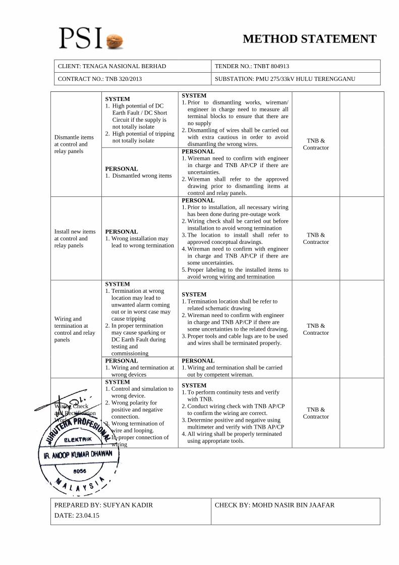
Dismantle items at control and relay panels
SYSTEM 1. High potential of DC
Earth Fault / DC Short Circuit if the supply is not totally isolate
2. High potential of tripping not totally isolate
SYSTEM 1. Prior to dismantling works, wireman/
engineer in charge need to measure all terminal blocks to ensure that there are no supply
2. Dismantling of wires shall be carried out with extra cautious in order to avoid dismantling the wrong wires. TNB &
Contractor
PERSONAL 1. Dismantled wrong items
PERSONAL 1. Wireman need to confirm with engineer
in charge and TNB AP/CP if there are uncertainties.
2. Wireman shall refer to the approved drawing prior to dismantling items at control and relay panels.
Install new items at control and relay panels
PERSONAL 1. Wrong installation may
lead to wrong termination
PERSONAL 1. Prior to installation, all necessary wiring
has been done during pre-outage work 2. Wiring check shall be carried out before
installation to avoid wrong termination 3. The location to install shall refer to
approved conceptual drawings. 4. Wireman need to confirm with engineer
in charge and TNB AP/CP if there are some uncertainties.
5. Proper labeling to the installed items to avoid wrong wiring and termination
TNB & Contractor
Wiring and termination at control and relay panels
SYSTEM 1. Termination at wrong
location may lead to unwanted alarm coming out or in worst case may cause tripping
2. In proper termination may cause sparking or DC Earth Fault during testing and commissioning
SYSTEM 1. Termination location shall be refer to
related schematic drawing 2. Wireman need to confirm with engineer
in charge and TNB AP/CP if there are some uncertainties to the related drawing.
3. Proper tools and cable lugs are to be used and wires shall be terminated properly.
TNB & Contractor
PERSONAL 1. Wiring and termination at
wrong devices
PERSONAL 1. Wiring and termination shall be carried
out by competent wireman.
Wiring Check and Rectification Works
SYSTEM 1. Control and simulation to
wrong device. 2. Wrong polarity for
positive and negative connection.
3. Wrong termination of wire and looping.
4. In-proper connection of wiring
SYSTEM 1. To perform continuity tests and verify
with TNB. 2. Conduct wiring check with TNB AP/CP
to confirm the wiring are correct. 3. Determine positive and negative using
multimeter and verify with TNB AP/CP 4. All wiring shall be properly terminated
using appropriate tools.
TNB & Contractor
PREPARED BY: SUFYAN KADIR DATE: 23.04.15
CHECK BY: MOHD NASIR BIN JAAFAR

METHOD STATEMENT
CONTRACT NO.: TNB 320/2013 TENDER NO.: TNBT 804913
WORK SCHEDULE
No. WORK DESCRIPTION Day 1
Working Hours 1 2 3 4 5 6 7 8 9
1 Obtain Permit to work
2. Investigation for RTCC Panel No. 1 (DH+RT1)
4. Isolation work at RTCC Panel No.1
5. RTCC Panel No.1 -Dismantling of faulty relay -Installation of new relay -Final Check -Handover to tester
Investigation for 275kV Bus Coupler Relay Panel (D04+R)
6. Isolation work for 275kV Bus Coupler Relay Panel (D04+R)
7. 275kV Bus Coupler Relay Panel (D04+R) -Dismantling of faulty relay -Installation of new relay -Final Check -Handover to tester
9. -Testing on going -Commissioning
METHOD STATEMENT
CLIENT: TENAGA NASIONAL BERHAD TENDER NO.: TNBT 804913
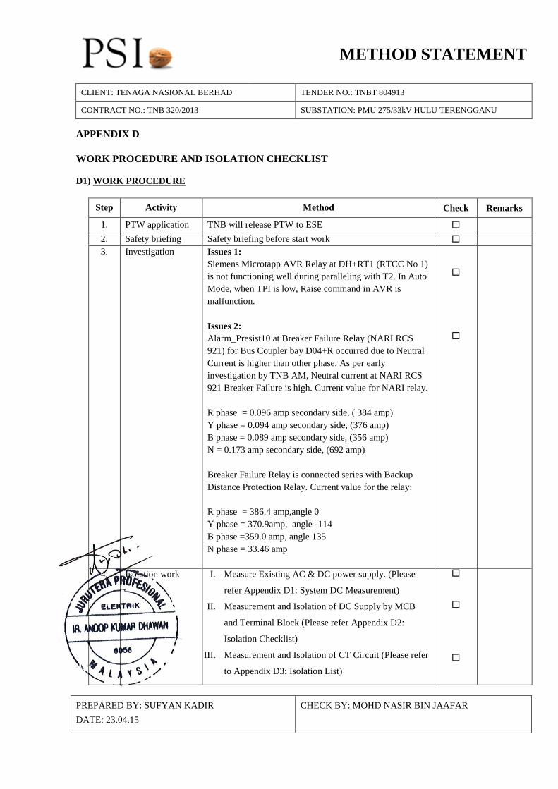
CONTRACT NO.: TNB 320/2013 SUBSTATION: PMU 275/33kV HULU TERENGGANU APPENDIX D WORK PROCEDURE AND ISOLATION CHECKLIST D1) WORK PROCEDURE
Step Activity Method Check Remarks
1. PTW application TNB will release PTW to ESE 2. Safety briefing Safety briefing before start work 3. Investigation Issues 1:
Siemens Microtapp AVR Relay at DH+RT1 (RTCC No 1) is not functioning well during paralleling with T2. In Auto Mode, when TPI is low, Raise command in AVR is malfunction. Issues 2: Alarm_Presist10 at Breaker Failure Relay (NARI RCS 921) for Bus Coupler bay D04+R occurred due to Neutral Current is higher than other phase. As per early investigation by TNB AM, Neutral current at NARI RCS 921 Breaker Failure is high. Current value for NARI relay. R phase = 0.096 amp secondary side, ( 384 amp) Y phase = 0.094 amp secondary side, (376 amp) B phase = 0.089 amp secondary side, (356 amp) N = 0.173 amp secondary side, (692 amp) Breaker Failure Relay is connected series with Backup Distance Protection Relay. Current value for the relay: R phase = 386.4 amp,angle 0 Y phase = 370.9amp, angle -114 B phase =359.0 amp, angle 135 N phase = 33.46 amp
4. Isolation work I. Measure Existing AC & DC power supply. (Please
refer Appendix D1: System DC Measurement)
II. Measurement and Isolation of DC Supply by MCB
and Terminal Block (Please refer Appendix D2:
Isolation Checklist)
III. Measurement and Isolation of CT Circuit (Please refer
to Appendix D3: Isolation List)
PREPARED BY: SUFYAN KADIR DATE: 23.04.15
CHECK BY: MOHD NASIR BIN JAAFAR

METHOD STATEMENT
CLIENT: TENAGA NASIONAL BERHAD TENDER NO.: TNBT 804913
CONTRACT NO.: TNB 320/2013 SUBSTATION: PMU 275/33kV HULU TERENGGANU
IV. Check (measure) all terminal block after isolation. To
re-confirm all terminal blocks are isolated as per
Appendix D2 and D3)
5. Dismantle faulty
relay
Issues 1: To dismantle faulty Siemens Microtapp AVR relay at RTCC Panel No.1 (The dismantle are based on investigation result) Issues 2: To dismantle faulty NARI RCS 921 Breaker Failure relay at 275kV Bus Coupler (D04+R) (The dismantle are based on investigation result)
6. Install new relay Issues 1: To install new Siemens Microtapp AVR relay at RTCC Panel No.1 (The installation are based on investigation result) Issues 2: To install new NARI RCS 921 Breaker Failure relay at 275kV Bus Coupler (D04+R) (The installation are based on investigation result)
7. Wiring work To do wiring base on approved drawing. 8. Testing Hand-over to TNB tester
PREPARED BY: SUFYAN KADIR DATE: 23.04.15
CHECK BY: MOHD NASIR BIN JAAFAR

METHOD STATEMENT
CLIENT: TENAGA NASIONAL BERHAD TENDER NO.: TNBT 804913
CONTRACT NO.: TNB 320/2013 SUBSTATION: PMU 275/33kV HULU TERENGGANU PHYSICAL CHECKLIST A) Safety Precaution (Prior to work Commencement) 1. Check permit to work (PTW) has been issued. 2. Identify panels under the scope of work and hang “DANGER: WORK IN PROGRESS” sign. 3. Ensure that the rest of the adjacent panels other than described in above item 2 are barricade/locked to define working area clearly. B) Visual Check of Initial Condition Visual inspection of all panels under the scope of work to identify a. Any Bare Wire or Not terminated Wire YES NO b. Wire which is in the list to be isolated but has been isolated YES NO earlier c. Unknown wire in the terminal block YES NO No. Description Remarks
PREPARED BY: SUFYAN KADIR DATE: 23.04.15
CHECK BY: MOHD NASIR BIN JAAFAR
METHOD STATEMENT
CLIENT: TENAGA NASIONAL BERHAD TENDER NO.: TNBT 804913
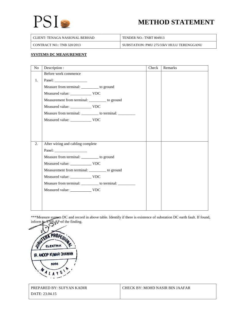
CONTRACT NO.: TNB 320/2013 SUBSTATION: PMU 275/33kV HULU TERENGGANU SYSTEMS DC MEASUREMENT
No Description : Check Remarks
1.
Before work commence
Panel: _________________
Measure from terminal: _________ to ground
Measured value: ___________ VDC
Measurement from terminal: _________ to ground
Measured value: ___________ VDC
Measure from terminal: _________ to terminal: _________
Measured value: ___________ VDC
2. After wiring and cabling complete
Panel: _________________
Measure from terminal: _________ to ground
Measured value: ___________ VDC
Measurement from terminal: _________ to ground
Measured value: ___________ VDC
Measure from terminal: _________ to terminal: _________
Measured value: ___________ VDC
***Measure system DC and record in above table. Identify if there is existence of substation DC earth fault. If found, inform to TNB AP of the finding.
PREPARED BY: SUFYAN KADIR DATE: 23.04.15
CHECK BY: MOHD NASIR BIN JAAFAR
METHOD STATEMENT
CLIENT: TENAGA NASIONAL BERHAD TENDER NO.: TNBT 804913
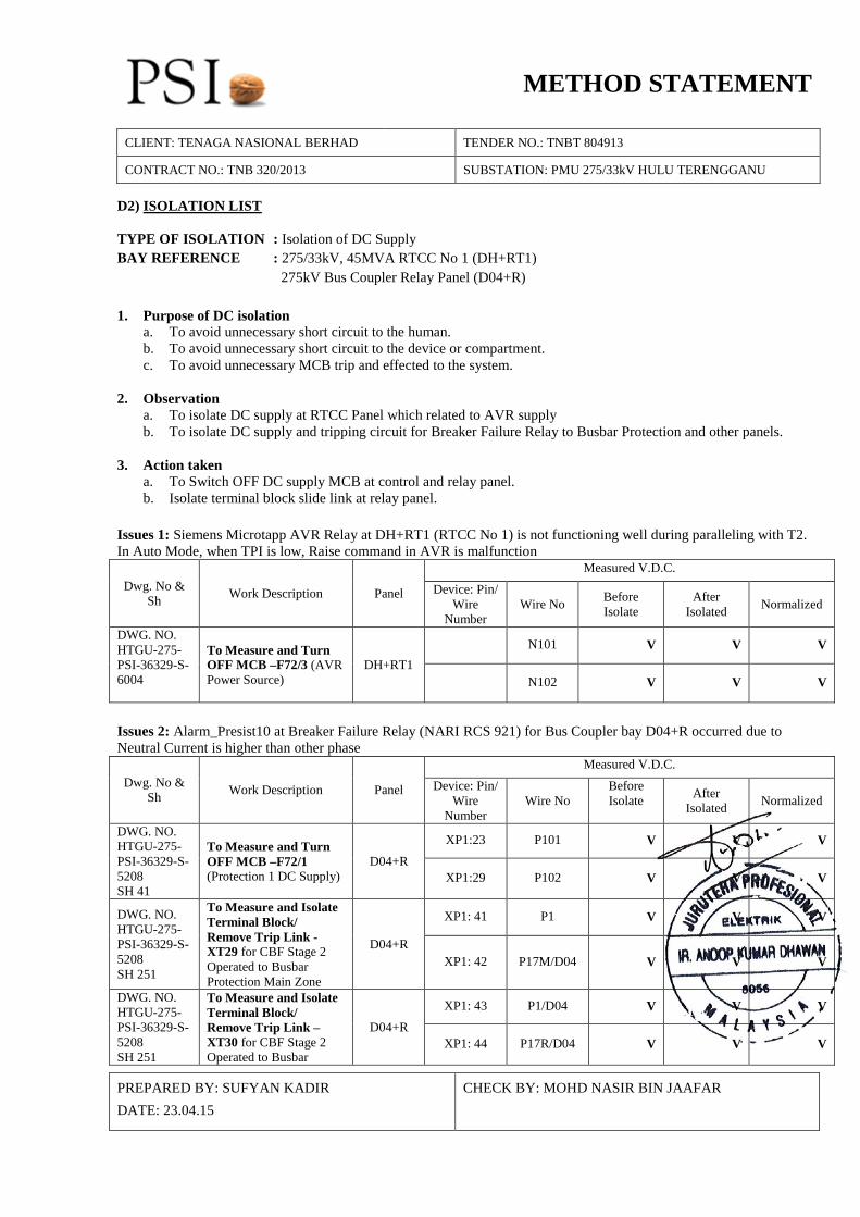
CONTRACT NO.: TNB 320/2013 SUBSTATION: PMU 275/33kV HULU TERENGGANU D2) ISOLATION LIST TYPE OF ISOLATION : Isolation of DC Supply BAY REFERENCE : 275/33kV, 45MVA RTCC No 1 (DH+RT1) 275kV Bus Coupler Relay Panel (D04+R) 1. Purpose of DC isolation
a. To avoid unnecessary short circuit to the human. b. To avoid unnecessary short circuit to the device or compartment. c. To avoid unnecessary MCB trip and effected to the system.
2. Observation
a. To isolate DC supply at RTCC Panel which related to AVR supply b. To isolate DC supply and tripping circuit for Breaker Failure Relay to Busbar Protection and other panels.
3. Action taken
a. To Switch OFF DC supply MCB at control and relay panel. b. Isolate terminal block slide link at relay panel.
Issues 1: Siemens Microtapp AVR Relay at DH+RT1 (RTCC No 1) is not functioning well during paralleling with T2. In Auto Mode, when TPI is low, Raise command in AVR is malfunction
Dwg. No & Sh Work Description Panel
Measured V.D.C. Device: Pin/
Wire Number
Wire No Before Isolate
After Isolated Normalized
DWG. NO. HTGU-275-PSI-36329-S-6004
To Measure and Turn OFF MCB –F72/3 (AVR Power Source)
DH+RT1 N101 V V V
N102 V V V
Issues 2: Alarm_Presist10 at Breaker Failure Relay (NARI RCS 921) for Bus Coupler bay D04+R occurred due to Neutral Current is higher than other phase
Dwg. No & Sh Work Description Panel
Measured V.D.C. Device: Pin/
Wire Number
Wire No Before Isolate After
Isolated Normalized
DWG. NO. HTGU-275-PSI-36329-S-5208 SH 41
To Measure and Turn OFF MCB –F72/1 (Protection 1 DC Supply)
D04+R XP1:23 P101 V V V
XP1:29 P102 V V V
DWG. NO. HTGU-275-PSI-36329-S-5208 SH 251
To Measure and Isolate Terminal Block/ Remove Trip Link -XT29 for CBF Stage 2 Operated to Busbar Protection Main Zone
D04+R
XP1: 41 P1 V V V
XP1: 42 P17M/D04 V V V
DWG. NO. HTGU-275-PSI-36329-S-5208 SH 251
To Measure and Isolate Terminal Block/ Remove Trip Link –XT30 for CBF Stage 2 Operated to Busbar
D04+R XP1: 43 P1/D04 V V V
XP1: 44 P17R/D04 V V V
PREPARED BY: SUFYAN KADIR DATE: 23.04.15
CHECK BY: MOHD NASIR BIN JAAFAR
METHOD STATEMENT
CLIENT: TENAGA NASIONAL BERHAD TENDER NO.: TNBT 804913
CONTRACT NO.: TNB 320/2013 SUBSTATION: PMU 275/33kV HULU TERENGGANU
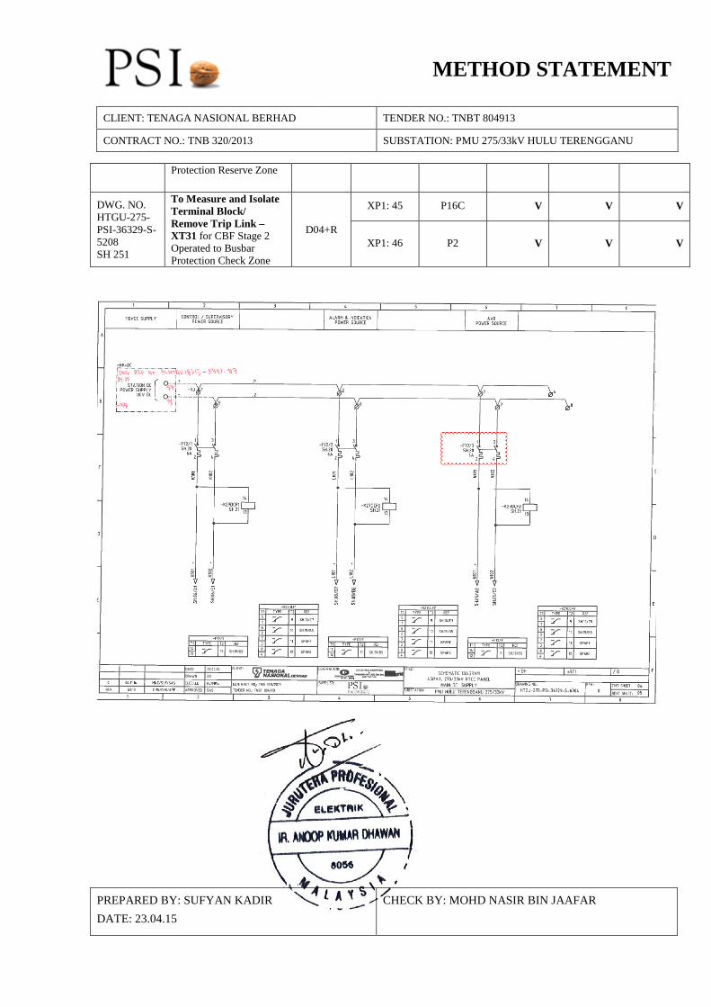
Protection Reserve Zone
DWG. NO. HTGU-275-PSI-36329-S-5208 SH 251
To Measure and Isolate Terminal Block/ Remove Trip Link –XT31 for CBF Stage 2 Operated to Busbar Protection Check Zone
D04+R
XP1: 45 P16C V V V
XP1: 46 P2 V V V
PREPARED BY: SUFYAN KADIR DATE: 23.04.15
CHECK BY: MOHD NASIR BIN JAAFAR
METHOD STATEMENT
CLIENT: TENAGA NASIONAL BERHAD TENDER NO.: TNBT 804913
CONTRACT NO.: TNB 320/2013 SUBSTATION: PMU 275/33kV HULU TERENGGANU
PREPARED BY: SUFYAN KADIR DATE: 23.04.15
CHECK BY: MOHD NASIR BIN JAAFAR
METHOD STATEMENT
CLIENT: TENAGA NASIONAL BERHAD TENDER NO.: TNBT 804913
CONTRACT NO.: TNB 320/2013 SUBSTATION: PMU 275/33kV HULU TERENGGANU
PREPARED BY: SUFYAN KADIR DATE: 23.04.15
CHECK BY: MOHD NASIR BIN JAAFAR
METHOD STATEMENT
CLIENT: TENAGA NASIONAL BERHAD TENDER NO.: TNBT 804913
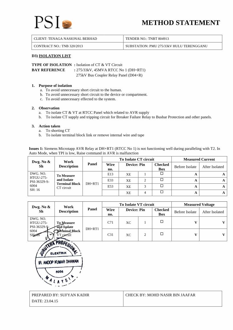
CONTRACT NO.: TNB 320/2013 SUBSTATION: PMU 275/33kV HULU TERENGGANU D3) ISOLATION LIST TYPE OF ISOLATION : Isolation of CT & VT Circuit BAY REFERENCE : 275/33kV, 45MVA RTCC No 1 (DH+RT1) 275kV Bus Coupler Relay Panel (D04+R) 1. Purpose of isolation
a. To avoid unnecessary short circuit to the human. b. To avoid unnecessary short circuit to the device or compartment. c. To avoid unnecessary effected to the system.
2. Observation
a. To isolate CT & VT at RTCC Panel which related to AVR supply b. To isolate CT supply and tripping circuit for Breaker Failure Relay to Busbar Protection and other panels.
3. Action taken
a. To shorting CT b. To isolate terminal block link or remove internal wire and tape
Issues 1: Siemens Microtapp AVR Relay at DH+RT1 (RTCC No 1) is not functioning well during paralleling with T2. In Auto Mode, when TPI is low, Raise command in AVR is malfunction
Dwg. No & Sh
Work Description Panel
To Isolate CT circuit Measured Current Wire no.
Device: Pin Checked Box Before Isolate After Isolated
DWG. NO. HTGU-275-PSI-36329-S-6004 SH: 16
To Measure and Isolate Terminal Block CT circuit
DH+RT1
E13 XE 1 A A
E33 XE 2 A A
E53 XE 3 A A
XE 4 A A
Dwg. No & Sh
Work Description Panel
To Isolate VT circuit Measured Voltage Wire no.
Device: Pin Checked Box Before Isolate After Isolated
DWG. NO. HTGU-275-PSI-36329-S-6004 SH: 16
To Measure and Isolate Terminal Block VT circuit
DH+RT1
C71 XC 1 V V
C31 XC 2 V V
PREPARED BY: SUFYAN KADIR DATE: 23.04.15
CHECK BY: MOHD NASIR BIN JAAFAR
METHOD STATEMENT
CLIENT: TENAGA NASIONAL BERHAD TENDER NO.: TNBT 804913
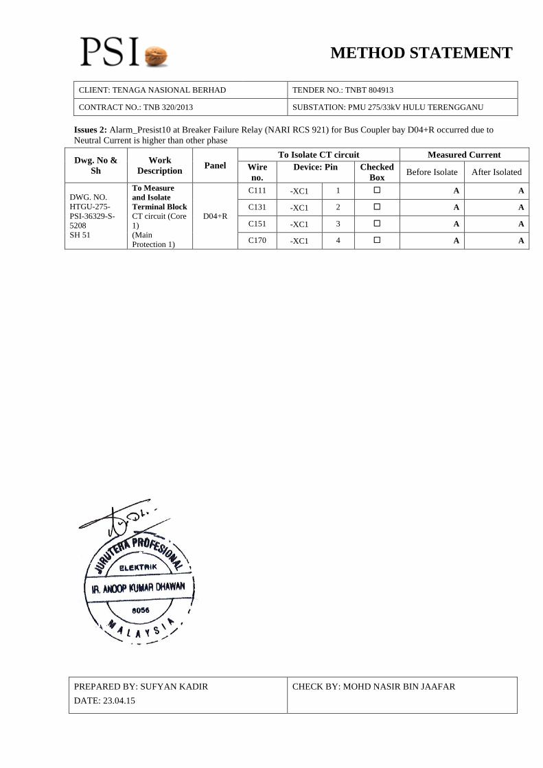
CONTRACT NO.: TNB 320/2013 SUBSTATION: PMU 275/33kV HULU TERENGGANU Issues 2: Alarm_Presist10 at Breaker Failure Relay (NARI RCS 921) for Bus Coupler bay D04+R occurred due to Neutral Current is higher than other phase
Dwg. No & Sh
Work Description Panel
To Isolate CT circuit Measured Current Wire no.
Device: Pin Checked Box Before Isolate After Isolated
DWG. NO. HTGU-275-PSI-36329-S-5208 SH 51
To Measure and Isolate Terminal Block CT circuit (Core 1) (Main Protection 1)
D04+R
C111 -XC1 1 A A
C131 -XC1 2 A A
C151 -XC1 3 A A
C170 -XC1 4 A A
PREPARED BY: SUFYAN KADIR DATE: 23.04.15
CHECK BY: MOHD NASIR BIN JAAFAR
METHOD STATEMENT
CLIENT: TENAGA NASIONAL BERHAD TENDER NO.: TNBT 804913
CONTRACT NO.: TNB 320/2013 SUBSTATION: PMU 275/33kV HULU TERENGGANU
PREPARED BY: SUFYAN KADIR DATE: 23.04.15
CHECK BY: MOHD NASIR BIN JAAFAR
METHOD STATEMENT
CLIENT: TENAGA NASIONAL BERHAD TENDER NO.: TNBT 804913
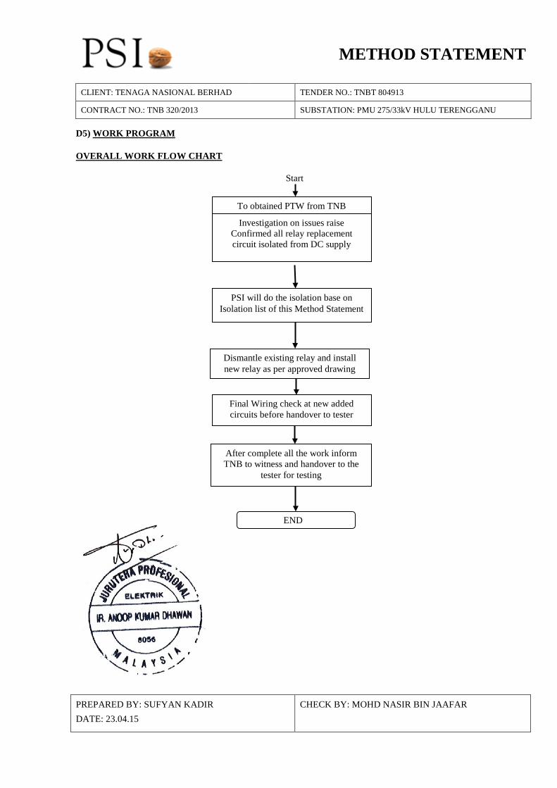
CONTRACT NO.: TNB 320/2013 SUBSTATION: PMU 275/33kV HULU TERENGGANU D5) WORK PROGRAM OVERALL WORK FLOW CHART
Start
To obtained PTW from TNB
Investigation on issues raise Confirmed all relay replacement circuit isolated from DC supply
PSI will do the isolation base on Isolation list of this Method Statement
Final Wiring check at new added circuits before handover to tester
After complete all the work inform TNB to witness and handover to the
tester for testing
Dismantle existing relay and install new relay as per approved drawing
END
PREPARED BY: SUFYAN KADIR DATE: 23.04.15
CHECK BY: MOHD NASIR BIN JAAFAR

METHOD STATEMENT
CLIENT: TENAGA NASIONAL BERHAD TENDER NO.: TNBT 804913
CONTRACT NO.: TNB 320/2013 SUBSTATION: PMU 275/33kV HULU TERENGGANU APPENDIX E CONTIGENCY PLAN Immediate action will be taken if any unwanted situation happens as below: 1) Action taken if any accident happen during do wiring etc.
Stop all work and report to TNB supervisor and TNB AP. Make sure the victim still conscious. Victim unconscious immediately send to hospital. PSI supervisor above will report to S.E and TNB PIC. Ask TNB AP for next cause of action Situations become worse stop all work.
2) Action taken when non tripping fault or hazard occurs during does any electrical work. (Non-tripping fault is
when fault happened, breaker will not trip. Only alarm will send to annunciator. Example: AC Supply Fail) Stop all work and report to TNB supervisor and TNB AP. Tester will Investigated location of fault happen. Asked all workers who at fault location. Discuss the outcome with the S.E and TNB PIC. Any conclusion TNB PIC and S.E will decide. Ask TNB AP for next cause of action
3) Action taken if any unknown tripping during electrical work.
Stop all work inside control room and inform ESE and TNB AP immediately Record tripping information from annunciation, prot relay, tx guard, bay no. etc Immediately study what caused tripping. Inform all the detail to the S.E and TNB PIC. Any conclusion depends on S.E and TNB PIC.
4) Action taken if any DC earth fault occurred during electrical work.
Stop all work inside control room. Asked all workers if any unusual things happen during do the work. Asked workers what wire they touch or cut. Investigated with the tester and clear the DC earth fault immediately. Inform to the S.E and TNB.
PREPARED BY: SUFYAN KADIR DATE: 23.04.15
CHECK BY: MOHD NASIR BIN JAAFAR


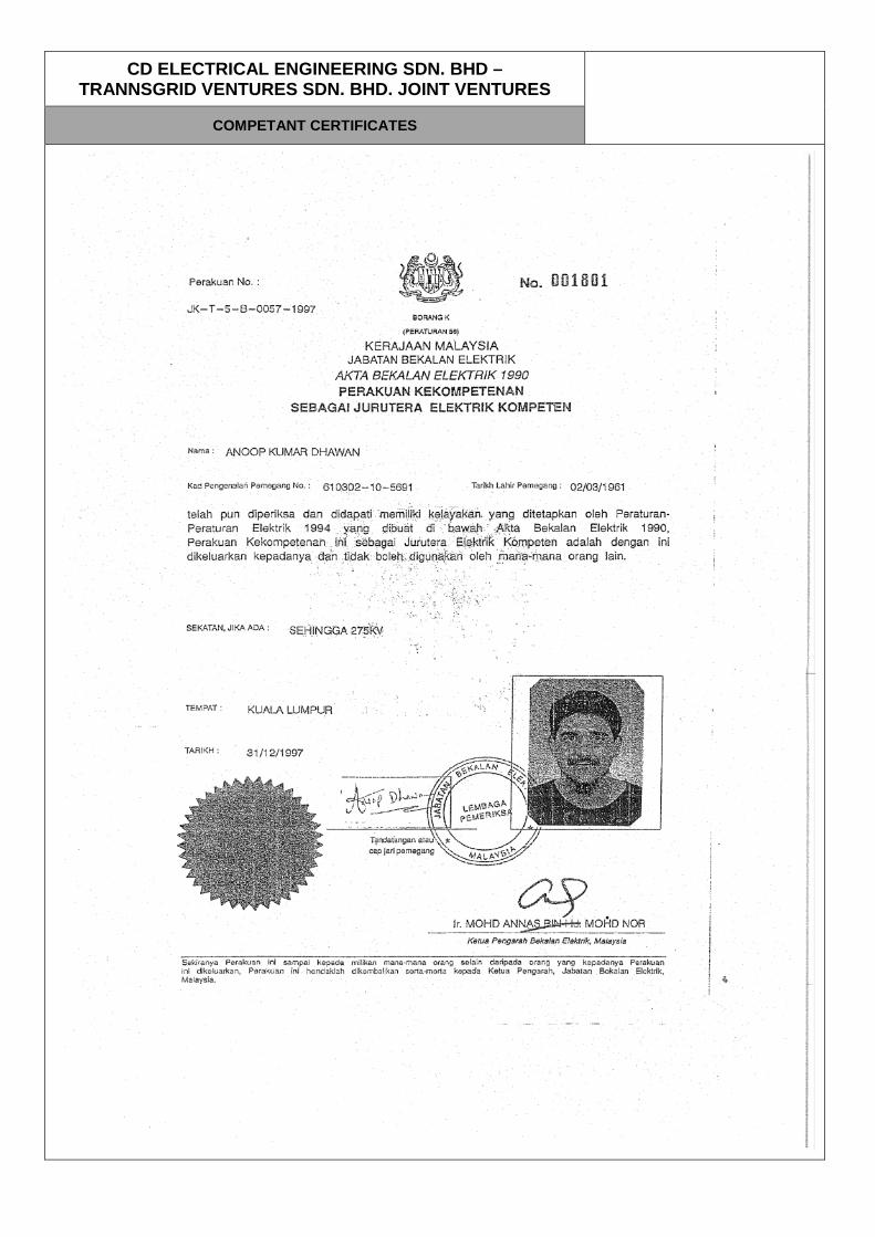
CD ELECTRICAL ENGINEERING SDN. BHD – TRANNSGRID VENTURES SDN. BHD. JOINT VENTURES
COMPETANT CERTIFICATES