moss - tarka-systems.nl · with dedicated connectors the bulkhead connectors on the side of the...
TRANSCRIPT
1
www.tarka-systems.nl v4.0
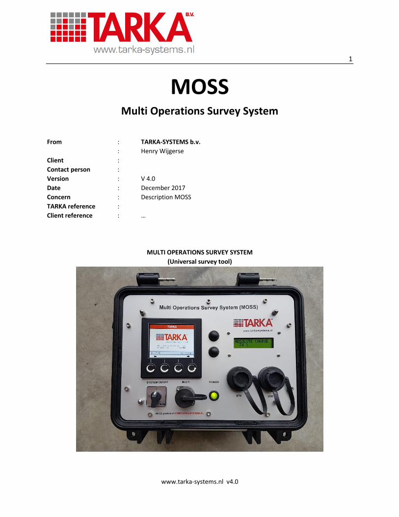
MOSS Multi Operations Survey System
From : TARKA-SYSTEMS b.v.
: Henry Wijgerse
Client :
Contact person :
Version : V 4.0
Date : December 2017
Concern : Description MOSS
TARKA reference :
Client reference : …
MULTI OPERATIONS SURVEY SYSTEM
(Universal survey tool)
2
www.tarka-systems.nl v4.0
Contents
1 INTRODUCTION ....................................................................................................................... 4
2 MOSS ....................................................................................................................................... 5
2.1 MOSS-SPECIFICATIONS ................................................................................................................. 5
2.2 MOSS-HARDWARE ........................................................................................................................ 6
2.2.1 Front panel items .................................................................................................................. 6
2.2.2 Side panel items .................................................................................................................... 7
2.2.3 Internal items ........................................................................................................................ 9
2.3 Power consumption .................................................................................................................... 12
2.4 SENSOR OPTIONS ........................................................................................................................ 13
2.5 MOSS SOFTWARE ........................................................................................................................ 14
2.6 MOSS-INTERFACES ...................................................................................................................... 15
2.7 DIMENSIONS ............................................................................................................................... 16
3 APPLICATIONS ........................................................................................................................ 17
3.1 Sensor types ................................................................................................................................ 17
3.2 Applied applications .................................................................................................................... 18
4 OPTIONS ................................................................................................................................ 20
3
www.tarka-systems.nl v4.0
Specification of updates:
Version Description Author Date
1.0 MOSS description HW Oct 2015
1.1 Added PCB info HW Nov 2015
1.2 Added extra dimensions and MOSS options HW Dec 2015
1.3 Added battery display and charge info HW Dec 2015
1.4 Added MOSS options and applications HW Jan 2016
1.5 Added information on USB HW Jan 2016
1.6 Added pictures of client specific MOSS units HW Jan 2016
1.7 Added info on power consumption HW Feb 2016
1.8 Updated after use of new board HW Nov 2016
1.9 Added detailed information and corrected some typos HW Dec 2016
2.0 Improved version HW Dec 2016
3.0 More universal text HW Oct 2017
4.0 Added information on 6-channel input board
Updated text
HW Dec 2017
4
www.tarka-systems.nl v4.0
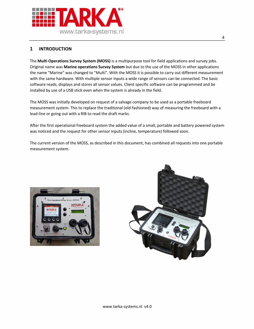
1 INTRODUCTION
The Multi Operations Survey System (MOSS) is a multipurpose tool for field applications and survey jobs.
Original name was Marine operations Survey System but due to the use of the MOSS in other applications
the name “Marine” was changed to “Multi”. With the MOSS it is possible to carry out different measurement
with the same hardware. With multiple sensor inputs a wide range of sensors can be connected. The basic
software reads, displays and stores all sensor values. Client specific software can be programmed and be
installed by use of a USB stick even when the system is already in the field.
The MOSS was initially developed on request of a salvage company to be used as a portable freeboard
measurement system. This to replace the traditional (old-fashioned) way of measuring the freeboard with a
lead-line or going out with a RIB to read the draft marks.
After the first operational freeboard system the added value of a small, portable and battery powered system
was noticed and the request for other sensor inputs (incline, temperature) followed soon.
The current version of the MOSS, as described in this document, has combined all requests into one portable
measurement system.
5
www.tarka-systems.nl v4.0
2 MOSS
The MOSS is a practical, robust, portable measurement solution for your monitoring and surveying needs.
Developed and manufactured by TARKA-SYSTEMS with the needs of Marine Surveyors and Naval Architects in
mind. It is not a single tool but a MULTIPURPOSE solution for many different measurements.
Save time and overhead by using the MOSS system for your surveys due to the pragmatic design, clear
functionality and the ability of reading a wide range of sensor inputs.
The functionality of the MOSS can be applied for Marine, Offshore, Salvage and Civil applications.
For special functionality the basic system can be extended on clients’ request.
The MOSS model is a handheld unit that provides the readout and storage of connected sensors.
The sensor values are gathered, displayed and stored on a USB stick. Average values can be calculated and
displayed during the measurements.
Additional to the data-gathering, visualization and storage there are possibilities to forward the data to an
overall main measurement system through one of the available ports on the MOSS.
2.1 MOSS-SPECIFICATIONS
The MOSS has the following specifications:
Portable / Battery powered
Sensor data gathering / visualization
Data logging on USB
Data forwarding wired/wireless
Time synchronization
RS232 or RS485 (Modbus RTU)
Ethernet / CAN / USB connection
Timer / Counter input
Digital inputs/outputs
Client specific software
Change of measurement program by reading new program from USB
(optional) PC-EXCEL tool for generating setup files (ini-file)
(optional) PC-EXCEL tool for generating reports from gathered data
More details on the above specifications is described in chapter 2.4.

6
www.tarka-systems.nl v4.0
2.2 MOSS-HARDWARE
The standard MOSS configuration consists of the following hardware:
Rugged travel case with shoulder strap
Frontplate with integrated items.
Battery with control board + charger
MOSS integration PCB
Rugged waterproof sensor connectors mounted on the side
Client specific solutions can differ from the basic description of the MOSS in this document.
2.2.1 Front panel items
The Frontplate consist of the following items:
Data Gathering and Display Module (DGDM)
Battery status display with control buttons
On/Off switch
Multi connector
ETH connector
USB connector
Power indicator light
DGDM The MOSS is equipped with a Data Gathering and Display Module (DGDM) which gathers and displays the sensor data. Data can be stored on a USB-stick through the USB port of the DGDM. There are two options of the DGDM. Both with all options but version 4 is equipped with a serial RS232 port while version 5 has a RS485 (MODBUS-RTU) port. Battery status display The battery display shows the status of the battery system. To scroll through the battery status display, press the buttons next to the display. The battery display shows all information which is available on the SMBUS protocol of the battery system. Some of the information is not relevant to the MOSS unit. On/off To switch the MOSS on, switch the on/off switch. The standard configuration switches of the main power after the battery control unit to the system. This provides leaking of current through additional electronics and results in a longer battery life.
7
www.tarka-systems.nl v4.0
Multi connector The Multi connector is an additional connector which can be used for several options depending on the configuration of the MOSS. Most common use is for optional Digital inputs and/or outputs. ETH connector The ETH connector is linked to the Ethernet port of the DGDM and network setups can be achieved. Time synchronization from an external source (NTP) can be achieved through the Ethernet port. USB connector The USB connector is used for uploading new programs into the DGDM. Software programs which uses an ini-file to create specific settings, the USB is also used to read the ini-files. When the program stores data on the USB, the USB must be connected during operation. USB must be formatted as fat32, an USB formatted as NTFS is not seen by the system 2.2.2 Side panel items
The side connectors are used to connect to the sensor cables. When client has already existing sensor cables
with dedicated connectors the bulkhead connectors on the side of the MOSS can be adjusted.
Depending on the configuration of the system and the demands of the client, the side panel can have
different layouts.
Examples of different side-layouts:
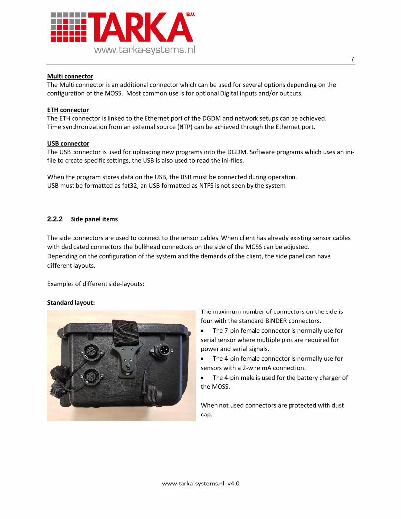
Standard layout:
The maximum number of connectors on the side is
four with the standard BINDER connectors.
The 7-pin female connector is normally use for
serial sensor where multiple pins are required for
power and serial signals.
The 4-pin female connector is normally use for
sensors with a 2-wire mA connection.
The 4-pin male is used for the battery charger of
the MOSS.
When not used connectors are protected with dust
cap.
8
www.tarka-systems.nl v4.0
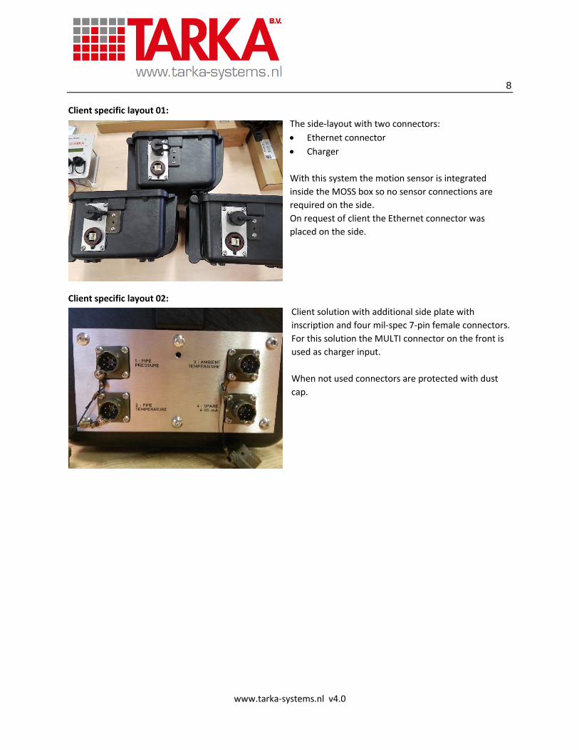
Client specific layout 01:
The side-layout with two connectors:
Ethernet connector
Charger
With this system the motion sensor is integrated
inside the MOSS box so no sensor connections are
required on the side.
On request of client the Ethernet connector was
placed on the side.
Client specific layout 02:
Client solution with additional side plate with
inscription and four mil-spec 7-pin female connectors.
For this solution the MULTI connector on the front is
used as charger input.
When not used connectors are protected with dust
cap.
9
www.tarka-systems.nl v4.0
2.2.3 Internal items
Battery system The MOSS is equipped with a battery system consisting of multiple items:
Battery
Control print
Status display
Battery charger
The battery is the smart type with SMbus protocol:
Lithium
14.40V
6600mAh
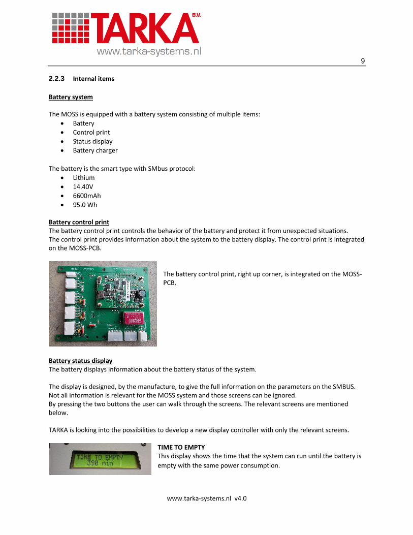
95.0 Wh Battery control print The battery control print controls the behavior of the battery and protect it from unexpected situations. The control print provides information about the system to the battery display. The control print is integrated on the MOSS-PCB.
The battery control print, right up corner, is integrated on the MOSS-PCB.
Battery status display The battery displays information about the battery status of the system. The display is designed, by the manufacture, to give the full information on the parameters on the SMBUS. Not all information is relevant for the MOSS system and those screens can be ignored. By pressing the two buttons the user can walk through the screens. The relevant screens are mentioned below. TARKA is looking into the possibilities to develop a new display controller with only the relevant screens.
TIME TO EMPTY This display shows the time that the system can run until the battery is
empty with the same power consumption.

10
www.tarka-systems.nl v4.0
RELATIVE CHARGE
This display shows the relative charge of the systems in percentage.
CURRENT
This display shows the current running in (charge) or out (consumption)
of the system.
VOLTAGE
This display shows the voltage of the system.
Voltage with active battery: approx. 14400 mV.
Battery charge
To recharge the MOSS the power supply cable (4-pins) must be connected to the related bulkhead connector
on the MOSS. Depending on the model the bulkhead connector is mounted on the side or on the front plate
(MULTI) of the MOSS. The charge loop is before the main switch so the MOSS can be charged when system is
turned off.
The MOSS (battery controller) is
charged with 12 Vdc.
11
www.tarka-systems.nl v4.0
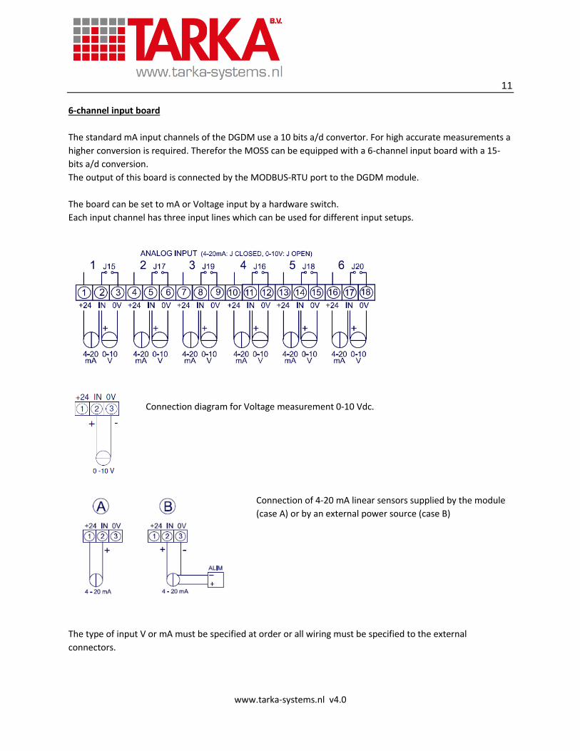
6-channel input board
The standard mA input channels of the DGDM use a 10 bits a/d convertor. For high accurate measurements a
higher conversion is required. Therefor the MOSS can be equipped with a 6-channel input board with a 15-
bits a/d conversion.
The output of this board is connected by the MODBUS-RTU port to the DGDM module.
The board can be set to mA or Voltage input by a hardware switch.
Each input channel has three input lines which can be used for different input setups.
Connection diagram for Voltage measurement 0-10 Vdc.
Connection of 4-20 mA linear sensors supplied by the module
(case A) or by an external power source (case B)
The type of input V or mA must be specified at order or all wiring must be specified to the external
connectors.
12
www.tarka-systems.nl v4.0
2.3 Power consumption
The MOSS power consumption is specified for different modes:
1. MOSS only
2. MOSS complete (with sensors)
1: MOSS only
The MOSS is active and charged, battery display is on and main switch is ON.
The Measurement screen is operational, no sensors are connected.
2: MOSS complete (with sensors)
The MOSS is active and charged, battery display is on and main switch is ON.
The Measurement screen is operational and all sensors are connected.
The number of sensors and the type of sensors can differ for each setup.
Time frame
Total battery capacity when fully charged: 6400 mAh.
Consumption (example)
1. MOSS only: 175 mA, 6400/175 = 36.5 hour
2. MOSS with motion sensor : indication : 220 mA, 6400/220 = 29.1 hour
Total consumption is relevant to type and number of connected sensors.
Consumption can differ due to connected sensor(s).
*above numbers are given as indication, real values can differ due to different system setup.
13
www.tarka-systems.nl v4.0
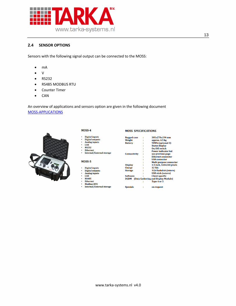
2.4 SENSOR OPTIONS
Sensors with the following signal output can be connected to the MOSS:
mA
V
RS232
RS485 MODBUS RTU
Counter Timer
CAN
An overview of applications and sensors option are given in the following document
MOSS-APPLICATIONS
14
www.tarka-systems.nl v4.0
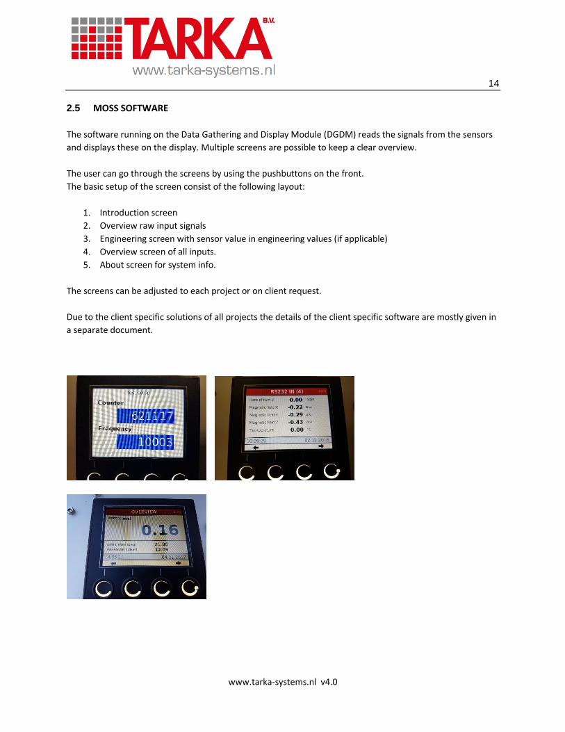
2.5 MOSS SOFTWARE
The software running on the Data Gathering and Display Module (DGDM) reads the signals from the sensors
and displays these on the display. Multiple screens are possible to keep a clear overview.
The user can go through the screens by using the pushbuttons on the front.
The basic setup of the screen consist of the following layout:
1. Introduction screen
2. Overview raw input signals
3. Engineering screen with sensor value in engineering values (if applicable)
4. Overview screen of all inputs.
5. About screen for system info.
The screens can be adjusted to each project or on client request.
Due to the client specific solutions of all projects the details of the client specific software are mostly given in
a separate document.
15
www.tarka-systems.nl v4.0
2.6 MOSS-INTERFACES
The MOSS system has a modular setup so it can read the most common sensor inputs. When the data output
type of a sensor is known the raw value can be read. With client specific software the engineering value can
be calculated and displayed on the display.
Available interface options DGDM:
2 CAN ISO 11898
USB Host (to connect USB mass storage)(fat32)
USB Device (to connect to PC)(fat32)
Ethernet
RS232 (NMEA) ontype-4 or RS485 (MODBUS-RTU) on type 5
Analog inputs (0-10V / 4-20 mA)
Counter / Timer
4 digital inputs
2 digital outputs
The DGDM is equipped with four special push buttons (tactile) which are used to control the measurement
program.
The sensors are connected through rugged waterproof connectors. Depending on the number of inputs the
number of connectors can change.
Each connector can have a power source output to power the related sensors, power can be battery-power
(15 Vdc) or boosted-power (24Vdc).
16
www.tarka-systems.nl v4.0
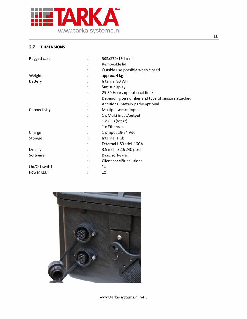
2.7 DIMENSIONS
Rugged case : 305x270x194 mm
: Removable lid
: Outside use possible when closed
Weight : approx. 4 kg
Battery : Internal 90 Wh
: Status display
: 25-50 Hours operational time
Depending on number and type of sensors attached
: Additional battery packs optional
Connectivity : Multiple sensor input
: 1 x Multi input/output
: 1 x USB (fat32)
: 1 x Ethernet
Charge : 1 x input 19-24 Vdc
Storage : Internal 1 Gb
: External USB stick 16Gb
Display : 3.5 inch, 320x240 pixel
Software : Basic software
: Client specific solutions
On/Off switch : 1x
Power LED : 1x
17
www.tarka-systems.nl v4.0
3 APPLICATIONS
With the DGDM-Type 5 the MOSS has the possibility to read:
RS485 (MODBUS-RTU) up to 32 sensors
2 CAN ISO 11898
Analog inputs (0-10V / 0-20 mA)
4 digital inputs
2 digital outputs
Optional – internal storage
With the above scope of inputs signals the MOSS can be used as a modular system for many different sensors
and many different measurements. When different measurement programs are required for a different type
of project the software can be changed by using a USB stick.
By placing an USB stick into the system the system will check the files on the stick. When a different program
is on the stick than installed on the DGDM that program is installed. When each client specific measurement
software is on a separate USB stick the MOSS can be used for multiple measurements without changing any
hardware.
The type of sensor is not important only the sensor should have one of the above protocols to be used
together with the MOSS. Sensors can be provided by TARKA-SYSTEMS.
3.1 Sensor types
Examples of sensors which can be read by the MOSS unit:
Pressure mA DGDM type 4/5
Temperature PT100 with convertor to mA DGDM type 4/5
Incline mA DGDM type 4/5
Incline RS485 (MODBUS-RTU) DGDM type 5
Strain gauge full bridge with convertor to mA DGDM type 4/5
Distance (freeboard) mA DGDM type 4/5
Distance RS485 (MODBUS-RTU) DGDM type 5
Wind sensor Serial RS232 NMEA DGDM type 4
Water Current Serial RS232 NMEA DGDM type 4
GPS Serial RS232 NMEA DGDM type 4
Motion (6DOF) Serial RS232 NMEA DGDM type 4
Motion (Roll & Pitch) Serial RS232 NMEA DGDM type 4
With the MODBUS RTU protocol up to 32 sensors can be connected in a bus-structure which allows the user
to carry out multiple measurements.

18
www.tarka-systems.nl v4.0
3.2 Applied applications
A short summary of applied applications:
Freeboard measurement
Sector Salvage
Sensors Ultrasonic sensor (RS485 MODBUS)
Incline sensor (RS485 MODBUS)
Software Read, display, store internal, store USB
Pipeline Services
Sector Civil
Sensors Pressure sensor – pipe pressure (4-20 mA)
Pt100 - pipe temperature (4-20mA)
Pt100 – ambient temperature (4-20mA)
Software Read, display, store internal, store USB
EXCEL tool for preparing measurement
EXCEL tool for generating pdf-report.
Underwater installations
Sector Diving
Sensors Pressure sensor – absolute (4-20 mA)
Pressure sensor – atmospheric (4-20mA)
Temperature sensor – ambient (4-20mA)
ADP sensor -water speed and current
Motion Measurement
Sector Offshore
Sensors Motion sensor (6DOF) or
Motion sensor (Roll&Pitch)
19
www.tarka-systems.nl v4.0
Additional to the above applied applications the MOSS could be used for the following applications:
Salvage monitoring and survey Marine survey of damaged vessels
Field measurement Incline experiments
Dry docking monitoring Floating dock monitoring
Semi-submersible monitoring Float-on/off monitoring
Heavy lift Load out
Pressure tests others………

20
www.tarka-systems.nl v4.0
4 OPTIONS
The MOSS is a multifunctional device and depending on the required specification the MOSS can be configured
in multiple ways related to hardware and software.
Below a summary of options:
MOSS (basic)
Hardware
o Rugged case with shoulder straps
o Data Gathering and Display Module (DGDM)
1. DGDM type 4
2. DGDM type 5
o Internal battery with status display
o Rugged sensor connectors
o USB / ETH connector
o Main switch with power led indicator
Software
o Basic Measurement software
1. Software RS485 MODBUS RTU
2. Software Analog input (4-20 mA / 0-10 Vdc)
3. Software RS232
4. Combi 1 & 2
o Software - Client specific solutions
Sensors (options)
Ultrasonic distance gauge 50 feet range (MODBUS RTU/RS232/ma)
Ultrasonic distance gauge 72 feet range (MODBUS RTU/RS232/ma)
Incline sensor (MODBUS RTU/mA)
Temperature sensor (PT100 (with mA conversion)/ mA / RS232)
GPS (RS232)
Wind (RS232)
Pressure sensors for Diving (absolute, relative, atmospheric)
All sensor of 4-20 mA (2-wire 15 or 24 Vdc source from case)
All RS232 NMEA sensors
Other options:
Special requests for software visualization
Client specific requests for hardware and software

21
www.tarka-systems.nl v4.0
Delivery:
Due to different requests the MOSS systems are made on order, normal delivery time within 6 weeks.
We have several demo systems available for urgent jobs.
Please specify your requirements for a MOSS that suits your demands.
Regards
Henry Wijgerse
TARKA-SYSTEMS