motion & drives - frequency inverters
TRANSCRIPT

C o m p a c t a n d c o m p l e t e
JX INVERTER
C o s t a n d e c o - f r i e n d l y »Co m m u n i c a t i o n s b u i l t - i n »
Q u a l i t y & re l i a b i l i t y y o u c a n d e p e n d o n »

1
2
The smallest gets integrated...
Omron fully understands your needs, which
is why we put quality and reliability first.
And we keep listening, so our products come
with new features and functionality that save
you time and money.
With the RFI filter built-in, and the
communications integrated as standard, the
JX provides a compact and complete solution
to a whole range of simple applications, such
as conveyor control.
Key features include:
• Ratings up to 7.5 kW
• RS485 Modbus built-in
• Side-by-side mounting
• EMC filter built-in
• PID function
• Micro-surge voltage suppression
• Automatic energy saving
• Emergency shut-off
• Second motor setting
• Auto carrier-frequency reduction
• PTC thermistor input
• Cooling fan switch control
• RoHS
Easy network integration
The RS485 Modbus is built into the RJ45 port in the inverter front, making it very easy to add inverters into the network without any extra option boards. Therefore, saving money and space.
Easy communications setting
Modbus commands are implemented even in low end CP1 PLC family by Modbus-RTU Easy Master functionality, making it easier than ever to integrate the inverters into the network.
Space and cost saving
The new JX has a built-in EMC filter that saves on costs and space compared with the standardexternal filter solution.1 ph : EN61800-3 cat. C13 ph : EN61800-3 cat. C2
120110
1009080706050403020100
Frequency (Hz)
Leve
l (dB
V)
Conducted emission data
Integrated EMC filter
No Filter
500k 1M 2M 5M 10M 20M 30M200150OMRON Function Block for Pulse Output Positioning.OMRON Function Block for Communications.
WWWWAARRRRRAAAANNNNTTYY
YYYYY EEEE AAA RRRRR SSSS
Sensor?
3 54
5
34
6
6
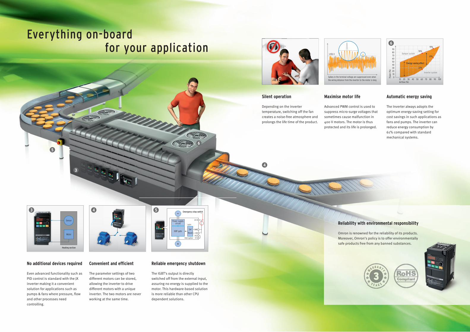
No additional devices required
Even advanced functionality such as PID control is standard with the JX inverter making it a convenient solution for applications such as pumps & fans where pressure, flow and other processes need controlling.
Automatic energy saving
The Inverter always adopts the optimum energy-saving setting for cost savings in such applications as fans and pumps. The inverter can reduce energy consumption by 61% compared with standard mechanical systems.
Reliability with environmental responsibility
Omron is renowned for the reliability of its products. Moreover, Omron’s policy is to offer environmentally safe products free from any banned substances.
Reliable emergency shutdown
The IGBT’s output is directly switched off from the external input, assuring no energy is supplied to the motor. This hardware-based solution is more reliable than other CPU dependent solutions.
Convenient and efficient
The parameter settings of two different motors can be stored, allowing the inverter to drive different motors with a unique inverter. The two motors are never working at the same time.
Silent operation
Depending on the inverter temperature, switching off the fan creates a noise-free atmosphere and prolongs the life time of the product.
Maximise motor life
Advanced PWM control is used tosuppress micro-surge voltages thatsometimes cause malfunction in 400 V motors. The motor is thus protected and its life is prolonged.
for your applicationEverything on-board
Heating section
Motor
Sensor
Emergency stop switch
IGBT gate
Power supplycircuit
SetReset
24 V
Latch
Interruption 0 VPCS
RS
EMR
M
~
9080706050403020100Po
wer (
%)
1,250 V76%
91%
61%
22%
Damper system
Energy-saving effect
Inverter system
Airflow (%)10 20 30 40 50 60 70 80 90 100
Spikes in the terminal voltage are suppressed even when the wiring distance from the inverter to the motor is long
6 Frequency inverters
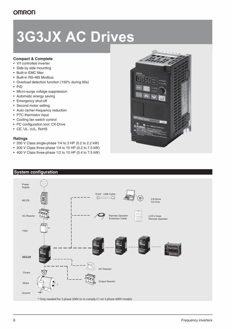
3G3JX AC DrivesCompact & Complete• V/f controlled inverter• Side by side mounting• Built-in EMC filter• Built-in RS-485 Modbus• Overload detection function (150% during 60s)• PID• Micro-surge voltage suppression• Automatic energy saving• Emergency shut-off• Second motor setting• Auto carrier-frequency reduction• PTC thermistor input• Cooling fan switch control• PC configuration tool: CX-Drive• CE, UL, cUL, RoHS
Ratings• 200 V Class single-phase 1/4 to 3 HP (0.2 to 2.2 kW)• 200 V Class three-phase 1/4 to 10 HP (0.2 to 7.5 kW)• 400 V Class three-phase 1/2 to 10 HP (0.4 to 7.5 kW)
System configuration
Choke
LCD 2 lines Remote Operator
Remote Operator Extansion Cable
* Only needed for 3 phase 200V or to comply C1 on 3 phase 400V models
Output Reactor
RJ45 - USB Cable
CX-Drive CX-One
*
MCCB
3G3JX
Filter
AC Reactor
Motor
Ground
Power Supply
DC Reactor

3G3JX 7
Type designation
200 V class
400 V class
Specifications
Single-phase: 3G3JX@ AB002 AB004 AB007 AB015 AB022 - - -
Three-phase: 3G3JX@ A2002 A2004 A2007 A2015 A2022 A2037 A2055 A2075Motor kW1
1. Based on a standard 3-Phase standard motor.
Applicable motor capacity 0.2 0.4 0.75 1.5 2.2 3.7 5.5 7.5
Ou
tpu
t ch
arac
teri
stic
s
Inverter capacity kVA200 V 0.4 0.9 1.3 2.4 3.4 5.5 8.3 11.0
240 V 0.5 1.0 1.6 2.9 4.1 6.6 9.9 13.3Rated output current (A) 1.4 2.6 4.0 7.1 10.0 15.9 24.0 32.0Max. output voltage Proportional to input voltage: 0…240 VMax. output frequency 400 Hz
Po
wer
su
pp
ly
Rated input voltageand frequency
Single-phase 200…240 V 50/60 Hz3-phase 200…240 V 50/60 Hz
Rated input current (A) 1.8 3.4 5.2 9.3 13.0 20.0 30.0 40.0Allowable voltage fluctuation -15%…+10%
Allowable frequency fluctuation +5%
Built-in filter EMC filter (C1 single phase)
Braking torque
At short-time decelerationAt capacitor feedback
Approx. 50%
50% for 3-phase
20 to 40% for 1-phase
Approx 20% to 40% Approx 20%
Cooling method Self cooling Forced-air-cooling
Three-phase: 3G3JX@ A4004 A4007 A4015 A4022 A4040 A4055 A4075Motor kW1
1. Based on a standard 3-Phase standard motor.
Applicable motor capacity 0.4 0.75 1.5 2.2 4.0 5.5 7.5
Ou
tpu
t ch
arac
teri
stic
s Inverter capacity kVA 380 V 0.9 1.6 2.5 3.6 5.6 8.5 10.5
480 V 1.2 2.0 3.1 4.5 7.1 10.8 13.3Rated output current (A) 1.5 2.5 3.8 5.5 8.6 13.0 16.0Max. output voltage Proportional to input voltage: 0…480 VMax. output frequency 400 Hz
Po
wer
su
pp
ly
Rated input voltageand frequency 3-phase 380…480 V 50/60 Hz
Rated input current (A) 2.0 3.3 5.0 7.0 11.0 16.5 20.0Allowable voltage fluctuation -15%…+10%
Allowable frequency fluctuation +5%
Built-in filter EMC filter C2 class
Braking torque
At short-time decelerationAt capacitor feedback
Approx. 50% Approx. 20% to 40% Approx. 20%
Cooling method Self cooling Forced-air-cooling
3G3JX series
A: Standard specs
J X A B 0 0 2 - E F
Voltage:B: Single-phase 200 VAC2: Three-phase 200 VAC4: Three-phase 400 VAC
Max. applicable motor output002: 1/4 HP (0.2 kW) ~
075: 10 HP (7.5 kW)
F: Built-in EMC Filter
E: Europe standard

8 Frequency inverters
Commom specifications
Specifications
Model number3G3JX@
Specifications
Co
ntr
ol f
un
ctio
ns
Control methods Phase-to-phase sinusoidal modulation PWM (V/f)
Output frequency range 0.5..400 Hz
Frequency precisionDigital set value: ±0.01% of the max. frequencyAnalogue set value: ±0.4% of the max. frequency (25 ±10 ºC)
Resolution of frequency set valueDigital set value: 0.1 Hz Analogue set value: 1/1000 of maximum frequency
Resolution of output frequency 0.1Hz
Overload capability 150% rated output current for one minute
Frequency set value 0 to 10 VDC (10KΩ), 4 to 20mA (250Ω), frequency setting volume (selectable), RS485 Modbus
V/f Characteristics Constant/ reduced torque
Fu
nct
ion
alit
y
Inputs signals
FW (forward), RV (reverse), CF1 to CF4 (multi-step speed), JG (jogging), DB (external DC injection braking), SET (2nd func-tion), 2CH (2-step acceleration/deceleration), FRS (free run), EXT (external trip), USP (USP function), SFT (soft lock), AT (analog current input function selection), RS (reset), PTC (thermistor input), STA (3-wire startup), STP (3-wire stop), F/R (3-wire forward/reverse), PID (PID selection), PIDC (PID integral reset), UP (UP of UP/DWN function), DWN (DWN of UP/DWN function), UDC (data clear of UP/DWN function), OPE (forced OPE mode), ADD (frequency addition), F-TM (forced terminal block), RDY (operation ready), SP-SET (special setting), EMR (emergency shutoff)
Output signals
RUN (signal during operation), FA1 (frequency arrival signal 1), FA2 (frequency arrival signal 2), OL (overload warning sig-nal), OD (PID excess deviation signal), AL (alarm signal), DC (analog input disconnection detection signal), FBV (PID FB status output), NDc (network error), LOG (logical operation result), ODc (communication option disconnected), LOC (light load signal)
Standard functions
AVR function, V/f characteristic selection, upper/lower limit, 16-step speeds, starting frequency adjustment, jogging operation, carrier frequency adjustment, PID control, frequency jump, analog gain/bias adjustment, S-shape acceleration/deceleration, electronic thermal characteristics/level adjustment, retry function, simplified torque boost, trip monitor, soft lock function, frequency conversion display, USP function, 2nd control function, motor rotation speed UP/DOWN, overcurrent suppression function
Analogue inputs 2 analogue inputs 0 to 10V (20KΩ), 4 to 20mA (250Ω)
Accel/Decel times 0.01 to 3000s (line/curve selection), 2nd accel/decel setting available
DisplayStatus indicator LED’s Run, Program, Power, Alarm, Power, Hz, Amps, Volume Led indicatorDigital operator: Available to monitor frequency reference, output current, output frequency
Pro
tect
ion
fu
nct
ion
s
Motor overload protection Electronic Thermal overload relay and PTC thermistor input
Instantaneous overcurrent 180% of rated current
Overload 150% for 1 minute
Overvoltage 790V for 400V type and 395 for 200V type
Momentary power loss Following items are selectable: Alarm, 0 Hz start, frequency output at interruption, maximum frequency
Cooling fin overheat Temperature monitor and error detection
Stall prevention level Selectable level applicable only at constant speed or during acceleration and constant speed
Ground fault Detected at power-on
Power charge indication On when power is supplied to the control part
Am
bie
nt
con
dit
ion
s Degree of protection IP20
Ambient humidity 90% RH or less (without condensation)
Storage temperature -20 ºC..+65 ºC (short-term temperature during transportation)
Ambient temperature −10°C to 50°C (Both the carrier frequency and output current need to be reduced at over 40°C.)
Installation Indoor (no corrosive gas, dust, etc.)
Installation height Max. 1000 m
Vibration 5.9 m/s2 (0.6G), 10 to 55 Hz (Complies with the test method specified in JIS C0040 (1999).)

3G3JX 9
IP 20 type 1/4 to 10 HP (0.2 to 7.5 kW)
Rasmi footprint Filters
Filter only needed by the 1-phase 200V or 3-phase 400V to comply with C1 EMC class.
Dimensions
Voltage class Max. applicable motor output kW Inverter model JX@ Figure
Dimensions in mm
W1 H1 W H D t1 D1 Weight
Single-phase 200 V
0.2 AB002 167 143 80 155
95.5
2.6
13 0.8
0.4 AB004 1 109.5 27 0.9
0.75 AB007 2
98 176 110 189
130.5 28 1.5
1.5 AB015 2157.5 6 55
2.3
2.2 AB022 2 2.4
Three-phase 200 V
0.2 A2002 1
67 143 80 155
95.5
2.6
13 0.8
0.4 A2004 1 109.5 27 0.9
0.75 A2007 1 132.5 50 1.1
1.5 A2015 2
98 176 110 189 157.5 6 55
2.2
2.2 A2022 22.4
3.7 A2037 2
5.5 A2055 2164 235 180 250 167.5 1.6 77.5 4.2
7.5 A2075 2
Three-phase400 V
0.4 A4004 2
98 176 110 189
130.5 2.6 28 1.5
0.75 A4007 2
157.5 6 55
2.3
1.5 A4015 2
2.42.2 A4022 2
4.0 A4040 2
5.5 A4055 2164 235 180 250 167.5 1.6 77.5 4.2
7.5 A4075 2
Figure 1 Figure 2
6
5
5
W
H1
W1
H
t1
D1
1.9 D
H1
5
H
W1
W
5
6
t1
D1
D1.9
Rasmi modelDimensions Weight
KGW H L X Y M
1x200 V
AX-FIJ1006-RE 81 40 193 183 57 M4 0.5
AX-FIJ1010-RE 112 47 226 216 88 M4 0.6
AX-FIJ1026-RE 112 47 226 216 88 M4 0.8
3x200 V
AX-FIJ2006-RE 81 50 193 183 57 M4 1.0
AX-FIJ2020-RE 112 50 226 216 88 M4 1.3
AX-FIJ2040-RE 182 55 289 279 150 M5 2.3
3x400 V
AX-FIJ3005-RE 112 45 226 216 88 M4 0.9
AX-FIJ3011-RE 112 45 226 216 88 M4 1.1
AX-FIJ3020-RE 182 45 289 279 150 M4 1.7

10 Frequency inverters
Input AC Reactor
DC Reactor
Output AC Reactor
Chokes
Voltage ReferenceDimensions Weight
KgA B2 C2 D E F
200VAX-RAI02800080-DE 120 70 120 80 52 5.5 1.78AX-RAI00880175-DE 120 80 120 80 62 5.5 2.35AX-RAI00350335-DE 180 85 190 140 55 6 5.5
400VAX-RAI07700042-DE 120 70 120 80 52 5.5 1.78AX-RAI03500090-DE 120 80 120 80 62 5.5 2.35AX-RAI01300170-DE 120 80 120 80 62 5.5 2.50
Voltage ReferenceDimensions Weight
KgA B C D E F G H
200V
AX-RC21400016-DE
84 113
96
101 66 5 7.5 2
1.22AX-RC10700032-DEAX-RC06750061-DE
105 1.60AX-RC03510093-DEAX-RC02510138-DE 116 1.95AX-RC01600223-DE 108 135 124 120 82 6.5
9.59.5 3.20
AX-RC01110309-DE120 152
136135 94 7 -
5.20AX-RC00840437-DE 146 6.00
400V
AX-RC43000020-DE
84 113
96
101 66 5 7.5 2
1.22AX-RC27000030-DE
105 1.60AX-RC14000047-DEAX-RC10100069-DE 116 1.95AX-RC06400116-DE 108 135 133 120 82 6.5
9.59.5 3.70
AX-RC04410167-DE120 152
136135 94 7 -
5.20AX-RC03350219-DE 146 6.00
Voltage ReferenceDimensions Weight
KgA B2 C2 D E F
200V
AX-RAO11500026-DE 120 70 120 80 52 5.5 1.78AX-RAO07600042-DE 120 70 120 80 52 5.5 1.78AX-RAO04100075-DE 120 80 120 80 62 5.5 2.35AX-RAO03000105-DE 120 80 120 80 62 5.5 2.35AX-RAO01830180-DE 180 85 190 140 55 6 5.5AX-RAO01150220-DE 180 85 190 140 55 6 5.5AX-RAO00950320-DE 180 85 205 140 55 6 6.5
400V
AX-RAO16300038-DE 120 70 120 80 52 5.5 1.78AX-RAO11800053-DE 120 80 120 80 52 5.5 2.35AX-RAO07300080-DE 120 80 120 80 62 5.5 2.35AX-RAO04600110-DE 180 85 190 140 55 6 5.5AX-RAO03600160-DE 180 85 205 140 55 6 6.5
X
H
YW Ø m
L
Ø d
Reference D diameter
MotorKW
Dimensions Weight KgL W H X Y m
AX-FER2102-RE 21 < 2.2 85 22 46 70 - 5 0.1AX-FER2515-RE 25 < 15 105 25 62 90 - 5 0.2

3G3JX 11
Standard connections
Terminal Block Specifications
Installation
Terminal Name Function (signal level)
R/L1, S/L2, T/N/L3Main circuit power supply input Used to connect line power to the drive.
Drives with single-phase 200 V input power use only terminals R/L1 and N (T/L3), terminal S/L2 is not available for these units
U/T1, V/T2, W/T3 Inverter output Used to connect the motor
PD/+1, P/+External DC reactor terminal Normally connected by the short-circuit bar. Remove the short-circuit bar between +1 and
P/+2 when a DC reactor is connected.
P/+, N/-Regenerative braking unit connection terminal Connect optional regenerative braking units (If a braking torque is required)
Grounding For grounding (grounding should conform to the local grounding code.)
Inverter
R (L1)
S (L2)
T/N (L3)
PCS
P24
U/T1
V/T2
W/T3
Motor
Note:To connect the DC reactor, remove the short-circuit bar.
For Source logic
5
4
4.7 kΩ
3
2
1
L
PD/+1
DC reactorP/+
N/-
11
24 V DC
CM2
10 kΩ
250 Ω
10 V DC
L
OI
O
H
AMFrequency meter
Frequency setting unit1 to 2 kΩ
4 to 20 mA DCPower supply input
Relay output
Common
AL1
AL2
AL0
RY
3-phase 200 V AC1-phase 200 V AC3-phase 400 V AC

12 Frequency inverters
Control Circuit
Side by side mounting
Type No. Signal name Function Signal level
Digital input
signals
PCS Input power supply
External power supply terminal for input signal (input)...At sink logicInternal power supply output terminal for input signal (output) ...At source logic
24 VDC ±10%
P24 Internal 24 VDC 24 VDC internal power supply 24 VDC ±10% 30 mA
1 Multi-function Input selection 1 Factory setting: Forward/ Stop
2 Multi-function Input selection 2 Factory setting: Reverse/ Stop
3 Multi-function Input selection 3 Factory setting: Fault reset
4 Multi-function Input selection 4 Factory setting: Emergency stop fault
5 Multi-function Input selection 5 Factory setting: Multi-step speed reference 1
L Multi-function Input selection common -- --
An
alo
g in
pu
t s
ign
al
H Frequency reference power supply 10 VDC 10 mA max
O Voltage frequency reference signal 0 to 10 VDC (10 KΩ)
OI Current frequency reference signal 4 to 20 mA (250 Ω)
L Frequency reference common --
Dig
ital
ou
tpu
t s
ign
als
AL2 NC output Factory default relay settingsUnder normal operation: AL2-AL0 ClosedUnder abnormal operation or power shutdown: AL1-AL0 Open
250 VAC 2.5 A30 VDC 3 A
AL1 NO output 250 VAC 1 A30 VDC 1 A
AL0 Relay Output common
11 Multi-function output terminal Factory setting: Frequency arrival signal at a constant speed 27 VDC50 mA max
CM2 Output signal common --
Mo
nit
or
Sig
nal
AMAnalog frequency monitor/Analog output current monitor Factory setting: Analog frequency monitor 0 to 10 VDC 1 mA

3G3JX 13
Input AC Reactor
DC Reactor
Output AC Reactor
3 phase 200 V class 400 V classMax. applicable
motor output kW Reference Current value A
InductancemH
Max. applicable motor output kW Reference Current value
AInductance
mH0.1 to 1.5 AX-RAI02800080-DE 8.0 2.8 0.4 to 1.5 AX-RAI07700042-DE 4.2 7.72.2 to 3.7 AX-RAI00880175-DE 17.5 0.88 2.2 to 4.0 AX-RAI03500090-DE 9.0 3.55.5 to 7.5 AX-RAI00350335-DE 33.5 0.35 5.5 to 7.5 AX-RAI01300170-DE 17.0 1.3
200 V class 400 V classMax. applicable
motor output kW Reference Current value A
InductancemH
Max. applicable motor output kW Reference Current value
AInductance
mH0.2 AX-RC21400016-DE 1.6 21.4 -0.4 AX-RC10700032-DE 3.2 10.7 0.4 AX-RC43000020-DE 2.0 43.00.7 AX-RC06750061-DE 6.1 6.75 0.7 AX-RC27000030-DE 3.0 27.01.5 AX-RC03510093-DE 9.3 3.51 1.5 AX-RC14000047-DE 4.7 14.02.2 AX-RC02510138-DE 13.8 2.51 2.2 AX-RC10100069-DE 6.9 10.13.7 AX-RC01600223-DE 22.3 1.60 4.0 AX-RC06400116-DE 11.6 6.405.5 AX-RC01110309-DE 30.9 1.11 5.5 AX-RC04410167-DE 16.7 4.417.5 AX-RC00840437-DE 43.7 0.84 7.5 AX-RC03350219-DE 21.9 3.35
200 V class 400 V classMax. applicable
motor output kW Reference Current value A
InductancemH
Max. applicable motor output kW Reference Current value
AInductance
mH0.1 to 0.4 AX-RAO11500026-DE 2.6 11.50 0.4 to 1.5 AX-RAO16300038-DE 3.8 16.30
0.75 AX-RAO07600042-DE 4.2 7.60 2.2 AX-RAO11800053-DE 5.3 11.801.5 AX-RAO04100075-DE 7.5 4.10 4.0 AX-RAO07300080-DE 8.0 7.302.2 AX-RAO03000105-DE 10.5 3.00 5.5 AX-RAO04600110-DE 11.0 4.603.7 AX-RAO01830160-DE 16.0 1.83 7.5 AX-RAO03600160-DE 16.0 3.605.5 AX-RAO01150220-DE 22.0 1.157.5 AX-RAO00950320-DE 32.0 0.95
MCCBPower supply
AC reactor JX
R/L1U
V
W
X
Y
Z
S/L2
T/L3
Powersupply
JX
DC reactor
R/L1
+1 P/+2
MCCB
S/L2
T/L3

14 Frequency inverters
3G3JX AC Drives (Inverters)
Ordering information
Specifications Model
Voltage class Max. applicable motor output (kW) Rated output current (A) Standard
Single-phase 200 V
0.2 1.4 3G3JX-AB002-EF
0.4 2.6 3G3JX-AB004-EF
0.75 4 3G3JX-AB007-EF
1.5 7.1 3G3JX-AB015-EF
2.2 10 3G3JX-AB022-EF
Three-phase 200 V
0.2 1.4 3G3JX-A2002-E
0.4 2.6 3G3JX-A2004-E
0.75 4 3G3JX-A2007-E
1.5 7.1 3G3JX-A2015-E
2.2 10 3G3JX-A2022-E
3.7 15.9 3G3JX-A2037-E
5.5 24 3G3JX-A2055-E
7.5 32 3G3JX-A2075-E
Three-phase400 V
0.4 1.5 3G3JX-A4004-EF
0.75 2.5 3G3JX-A4007-EF
1.5 3.8 3G3JX-A4015-EF
2.2 5.5 3G3JX-A4022-EF
4.0 8.6 3G3JX-A4040-EF
5.5 13 3G3JXA4055-EF
7.5 16 3G3JXA4075-EF
ChokeA
B BLCD 2 lines Remote Operator
Remote Operator Extansion Cable
A
A
C C C C
A Output reactor
B D
A
USB Cable CX-Drive CX-One
MCCB
3G3JX
Filter
AC Reactor
Motor
Ground
Power Supply
DC Reactor
* Only needed for 3 phase 200V or to comply C1 on 3 phase 400V models
*

3G3JX 15
A Line Filters 3G3AX-FIJ
A Input AC Reactors 3G3AX-RAI
A DC Reactors 3G3AX-RC
A Chokes 3G3AX-FER
A Output AC Reactors 3G3AX-RAO
B Accessories
D Computer software
Inverter Line filter Rasmi
Voltage Model JX-@ Reference Rated current (A) Weight (kg)
1-Phase 200 VAC
AB002 / AB004 AX-FIJ1006-RE 6 0.5
AB007 AX-FIJ1010-RE 10 0.6
AB015 / AB022 AX-FIJ1026-RE 26 0.8
3-Phase 200 VAC
A2002 / A2004 / A2007 AX-FIJ2006-RE 6 1.0
A2015 / A2022 / A2037 AX-FIJ2020-RE 20 1.3
A2055 / A2075 AX-FIJ2040-RE 40 2.3
3-Phase 400 VAC
A4004 / A4007 /A4015 AX-FIJ3005-RE 5 0.9
A4022 /A4040 AX-FIJ3011-RE 11 1.1
A4055 / A4075 AX-FIJ3020-RE 20 1.7
Inverter AC Reactor
Voltage Model JX-@ Reference
3-Phase 200 VAC
A2002 / A2004 / A2007 AX-RAI02800080-DE
A2015 / A2022 / A2037 AX-RAI00880175-DE
A2055 / A2075 AX-RAI00350335-DE
1-Phase 200 VAC
AB002 / AB004
Under developmentAB007
AB015 / AB022
3-Phase 400 VAC
A4004 / A4007 / A4015 AX-RAI07700042-DE
A4022 / A4040 AX-RAI03500090-DE
A4055 / A4075 AX-RAI01300170-DE
200V single phase 200V 3-phase 400V 3-phase
Inverter DC Reactor Inverter DC Reactor Inverter DC Reactor
JX-AB002 AX-RC10700032-DE JX-A2002 AX-RC21400016-DE -
JX-AB004 AX-RC06750061-DE JX-A2004 AX-RC10700032-DE JX-A4004 AX-RC43000020-DE
JX-AB007 AX-RC03510093-DE JX-A2007 AX-RC06750061-DE JX-A4007 AX-RC27000030-DE
JX-AB015 AX-RC02510138-DE JX-A2015 AX-RC03510093-DE JX-A4015 AX-RC14000047-DE
JX-AB022 AX-RC01600223-DE JX-A2022 AX-RC02510138-DE JX-A4022 AX-RC10100069-DE
-JX-A2037 AX-RC01600223-DE JX-A4040 AX-RC06400116-DE
JX-A2055 AX-RC01110309-DE JX-A4055 AX-RC04410167-DE
JX-A2075 AX-RC00840437-DE JX-A4075 AX-RC03350219-DE
Model Diameter Description
AX-FER2102-RE 21 For 2.2 KW motors or below
AX-FER2515-RE 25 For 7.5 KW motors or below
Inverter AC Reactor
Voltage Model JX-@ Reference
200 VAC
A2001 / A2002 / A2004 AB001 / AB002 / AB004 AX-RAO11500026-DE
A2007/AB007 AX-RAO07600042-DE
A2015 / AB015 AX-RAO04100075-DE
A2022 / AB022 AX-RAO03000105-DE
A2037 AX-RAO01830160-DE
A2055 AX-RAO01150220-DE
A2075 AX-RAO00950320-DE
400 VAC
A4004 / A4007 / A4015 AX-RAO16300038-DE
A4022 AX-RAO11800053-DE
A4040 AX-RAO07300080-DE
A4055 AX-RAO04600110-DE
A4075 AX-RAO03600160-DE
Types Model Description Functions
Dig
ital
oper
ator 3G3AX-OP05 LCD remote
operator
2 Line LCD remote opera-tor with copy function, cable length max. 3m.
3G3AX-CAJOP300-EE Remote operator cable
3 meters cable for con-necting remote operator
Acc
esso
ries
3G3AX-PCACN2 USB converter / USB cable
RJ45 to USB connection cable
3G3AX-CTB020-EE RJ45 T-Branch cable
T cable for RS-422 connection
Types Model Description Installation
Sof
twar
e CX-Drive Computer software
Configuration and monitor-ing drives
CX-One Computer software
Configuration and monitor-ing FA systems
In the interest of product improvement, specifications are subject to change without notice.
ALL DIMENSIONS SHOWN ARE IN MILLIMETERS.
To convert millimeters into inches, multiply by 0.03937. To convert grams into ounces, multiply by 0.03527.
Cat. No. I110E-EN-01B

Terms and Conditions of Sale1. Offer; Acceptance. These terms and conditions (these "Terms") are deemed
part of all quotes, agreements, purchase orders, acknowledgments, price lists,catalogs, manuals, brochures and other documents, whether electronic or inwriting, relating to the sale of products or services (collectively, the "Products")by Omron Electronics LLC and its subsidiary companies (“Omron”). Omronobjects to any terms or conditions proposed in Buyer’s purchase order or otherdocuments which are inconsistent with, or in addition to, these Terms.
2. Prices; Payment Terms. All prices stated are current, subject to change with-out notice by Omron. Omron reserves the right to increase or decrease priceson any unshipped portions of outstanding orders. Payments for Products aredue net 30 days unless otherwise stated in the invoice.
3. Discounts. Cash discounts, if any, will apply only on the net amount of invoicessent to Buyer after deducting transportation charges, taxes and duties, and willbe allowed only if (i) the invoice is paid according to Omron’s payment termsand (ii) Buyer has no past due amounts.
4. Interest. Omron, at its option, may charge Buyer 1-1/2% interest per month orthe maximum legal rate, whichever is less, on any balance not paid within thestated terms.
5. Orders. Omron will accept no order less than $200 net billing. 6. Governmental Approvals. Buyer shall be responsible for, and shall bear all
costs involved in, obtaining any government approvals required for the impor-tation or sale of the Products.
7. Taxes. All taxes, duties and other governmental charges (other than generalreal property and income taxes), including any interest or penalties thereon,imposed directly or indirectly on Omron or required to be collected directly orindirectly by Omron for the manufacture, production, sale, delivery, importa-tion, consumption or use of the Products sold hereunder (including customsduties and sales, excise, use, turnover and license taxes) shall be charged toand remitted by Buyer to Omron.
8. Financial. If the financial position of Buyer at any time becomes unsatisfactoryto Omron, Omron reserves the right to stop shipments or require satisfactorysecurity or payment in advance. If Buyer fails to make payment or otherwisecomply with these Terms or any related agreement, Omron may (without liabil-ity and in addition to other remedies) cancel any unshipped portion of Prod-ucts sold hereunder and stop any Products in transit until Buyer pays allamounts, including amounts payable hereunder, whether or not then due,which are owing to it by Buyer. Buyer shall in any event remain liable for allunpaid accounts.
9. Cancellation; Etc. Orders are not subject to rescheduling or cancellationunless Buyer indemnifies Omron against all related costs or expenses.
10. Force Majeure. Omron shall not be liable for any delay or failure in deliveryresulting from causes beyond its control, including earthquakes, fires, floods,strikes or other labor disputes, shortage of labor or materials, accidents tomachinery, acts of sabotage, riots, delay in or lack of transportation or therequirements of any government authority.
11. Shipping; Delivery. Unless otherwise expressly agreed in writing by Omron:a. Shipments shall be by a carrier selected by Omron; Omron will not drop ship
except in “break down” situations.b. Such carrier shall act as the agent of Buyer and delivery to such carrier shall
constitute delivery to Buyer;c. All sales and shipments of Products shall be FOB shipping point (unless oth-
erwise stated in writing by Omron), at which point title and risk of loss shallpass from Omron to Buyer; provided that Omron shall retain a security inter-est in the Products until the full purchase price is paid;
d. Delivery and shipping dates are estimates only; ande. Omron will package Products as it deems proper for protection against nor-
mal handling and extra charges apply to special conditions.12. Claims. Any claim by Buyer against Omron for shortage or damage to the
Products occurring before delivery to the carrier must be presented in writingto Omron within 30 days of receipt of shipment and include the original trans-portation bill signed by the carrier noting that the carrier received the Productsfrom Omron in the condition claimed.
13. Warranties. (a) Exclusive Warranty. Omron’s exclusive warranty is that theProducts will be free from defects in materials and workmanship for a period oftwelve months from the date of sale by Omron (or such other period expressedin writing by Omron). Omron disclaims all other warranties, express or implied.(b) Limitations. OMRON MAKES NO WARRANTY OR REPRESENTATION,EXPRESS OR IMPLIED, ABOUT NON-INFRINGEMENT, MERCHANTABIL-
ITY OR FITNESS FOR A PARTICULAR PURPOSE OF THE PRODUCTS.BUYER ACKNOWLEDGES THAT IT ALONE HAS DETERMINED THAT THEPRODUCTS WILL SUITABLY MEET THE REQUIREMENTS OF THEIRINTENDED USE. Omron further disclaims all warranties and responsibility ofany type for claims or expenses based on infringement by the Products or oth-erwise of any intellectual property right. (c) Buyer Remedy. Omron’s sole obli-gation hereunder shall be, at Omron’s election, to (i) replace (in the formoriginally shipped with Buyer responsible for labor charges for removal orreplacement thereof) the non-complying Product, (ii) repair the non-complyingProduct, or (iii) repay or credit Buyer an amount equal to the purchase price ofthe non-complying Product; provided that in no event shall Omron be responsi-ble for warranty, repair, indemnity or any other claims or expenses regardingthe Products unless Omron’s analysis confirms that the Products were prop-erly handled, stored, installed and maintained and not subject to contamina-tion, abuse, misuse or inappropriate modification. Return of any Products byBuyer must be approved in writing by Omron before shipment. Omron Compa-nies shall not be liable for the suitability or unsuitability or the results from theuse of Products in combination with any electrical or electronic components,circuits, system assemblies or any other materials or substances or environ-ments. Any advice, recommendations or information given orally or in writing,are not to be construed as an amendment or addition to the above warranty.See http://www.omron247.com or contact your Omron representative for pub-lished information.
14. Limitation on Liability; Etc. OMRON COMPANIES SHALL NOT BE LIABLEFOR SPECIAL, INDIRECT, INCIDENTAL, OR CONSEQUENTIAL DAMAGES,LOSS OF PROFITS OR PRODUCTION OR COMMERCIAL LOSS IN ANYWAY CONNECTED WITH THE PRODUCTS, WHETHER SUCH CLAIM ISBASED IN CONTRACT, WARRANTY, NEGLIGENCE OR STRICT LIABILITY.Further, in no event shall liability of Omron Companies exceed the individualprice of the Product on which liability is asserted.
15. Indemnities. Buyer shall indemnify and hold harmless Omron Companies andtheir employees from and against all liabilities, losses, claims, costs andexpenses (including attorney's fees and expenses) related to any claim, inves-tigation, litigation or proceeding (whether or not Omron is a party) which arisesor is alleged to arise from Buyer's acts or omissions under these Terms or inany way with respect to the Products. Without limiting the foregoing, Buyer (atits own expense) shall indemnify and hold harmless Omron and defend or set-tle any action brought against such Companies to the extent based on a claimthat any Product made to Buyer specifications infringed intellectual propertyrights of another party.
16. Property; Confidentiality. Any intellectual property in the Products is the exclu-sive property of Omron Companies and Buyer shall not attempt to duplicate itin any way without the written permission of Omron. Notwithstanding anycharges to Buyer for engineering or tooling, all engineering and tooling shallremain the exclusive property of Omron. All information and materials suppliedby Omron to Buyer relating to the Products are confidential and proprietary,and Buyer shall limit distribution thereof to its trusted employees and strictlyprevent disclosure to any third party.
17. Export Controls. Buyer shall comply with all applicable laws, regulations andlicenses regarding (i) export of products or information; (iii) sale of products to“forbidden” or other proscribed persons; and (ii) disclosure to non-citizens ofregulated technology or information.
18. Miscellaneous. (a) Waiver. No failure or delay by Omron in exercising any rightand no course of dealing between Buyer and Omron shall operate as a waiverof rights by Omron. (b) Assignment. Buyer may not assign its rights hereunderwithout Omron's written consent. (c) Law. These Terms are governed by thelaw of the jurisdiction of the home office of the Omron company from whichBuyer is purchasing the Products (without regard to conflict of law princi-ples). (d) Amendment. These Terms constitute the entire agreement betweenBuyer and Omron relating to the Products, and no provision may be changedor waived unless in writing signed by the parties. (e) Severability. If any provi-sion hereof is rendered ineffective or invalid, such provision shall not invalidateany other provision. (f) Setoff. Buyer shall have no right to set off any amountsagainst the amount owing in respect of this invoice. (g) Definitions. As usedherein, “including” means “including without limitation”; and “Omron Compa-nies” (or similar words) mean Omron Corporation and any direct or indirectsubsidiary or affiliate thereof.
Certain Precautions on Specifications and Use1. Suitability of Use. Omron Companies shall not be responsible for conformity
with any standards, codes or regulations which apply to the combination of theProduct in the Buyer’s application or use of the Product. At Buyer’s request,Omron will provide applicable third party certification documents identifyingratings and limitations of use which apply to the Product. This information byitself is not sufficient for a complete determination of the suitability of the Prod-uct in combination with the end product, machine, system, or other applicationor use. Buyer shall be solely responsible for determining appropriateness ofthe particular Product with respect to Buyer’s application, product or system.Buyer shall take application responsibility in all cases but the following is anon-exhaustive list of applications for which particular attention must be given:(i) Outdoor use, uses involving potential chemical contamination or electricalinterference, or conditions or uses not described in this document.(ii) Use in consumer products or any use in significant quantities. (iii) Energy control systems, combustion systems, railroad systems, aviationsystems, medical equipment, amusement machines, vehicles, safety equip-ment, and installations subject to separate industry or government regulations. (iv) Systems, machines and equipment that could present a risk to life or prop-erty. Please know and observe all prohibitions of use applicable to this Prod-uct. NEVER USE THE PRODUCT FOR AN APPLICATION INVOLVING SERIOUSRISK TO LIFE OR PROPERTY OR IN LARGE QUANTITIES WITHOUTENSURING THAT THE SYSTEM AS A WHOLE HAS BEEN DESIGNED TO
ADDRESS THE RISKS, AND THAT THE OMRON’S PRODUCT IS PROP-ERLY RATED AND INSTALLED FOR THE INTENDED USE WITHIN THEOVERALL EQUIPMENT OR SYSTEM.
2. Programmable Products. Omron Companies shall not be responsible for theuser’s programming of a programmable Product, or any consequence thereof.
3. Performance Data. Data presented in Omron Company websites, catalogsand other materials is provided as a guide for the user in determining suitabil-ity and does not constitute a warranty. It may represent the result of Omron’stest conditions, and the user must correlate it to actual application require-ments. Actual performance is subject to the Omron’s Warranty and Limitationsof Liability.
4. Change in Specifications. Product specifications and accessories may bechanged at any time based on improvements and other reasons. It is our prac-tice to change part numbers when published ratings or features are changed,or when significant construction changes are made. However, some specifica-tions of the Product may be changed without any notice. When in doubt, spe-cial part numbers may be assigned to fix or establish key specifications foryour application. Please consult with your Omron’s representative at any timeto confirm actual specifications of purchased Product.
5. Errors and Omissions. Information presented by Omron Companies has beenchecked and is believed to be accurate; however, no responsibility is assumedfor clerical, typographical or proofreading errors or omissions.

OMRON ELECTRONICS LLC • THE AMERICAS HEADQUARTERS
Schaumburg, IL USA • 847.843.7900 • 800.556.6766 • www.omron247.com
OMRON CANADA, INC. • HEAD OFFICE
Toronto, ON, Canada • 416.286.6465 • 866.986.6766 • www.omron247.com
OMRON ELETRÔNICA DO BRASIL LTDA • HEAD OFFICESão Paulo, SP, Brasil • 55.11.2101.6300 • www.omron.com.br
OMRON ELECTRONICS MEXICO SA DE CV • HEAD OFFICEApodaca, N.L. • 52.811.156.99.10 • 001.800.556.6766 • [email protected]
OMRON ARGENTINA • SALES OFFICECono Sur • 54.11.4783.5300
OMRON CHILE • SALES OFFICESantiago • 56.9.9917.3920
OTHER OMRON LATIN AMERICA SALES54.11.4783.5300
© 2009 Omron Electronics LLC
ALL DIMENSIONS SHOWN ARE IN MILLIMETERS.To convert millimeters into inches, multiply by 0.03937. To convert grams into ounces, multiply by 0.03527.
Note: This datasheet is provided as a guideline for selecting products. Do not use this document to operate the Unit.
Cat. No. I110E-EN-01B 01/10 Specifications are subject to change without notice.