motional emf - department of physics emf conducting rod moving across region of uniform magnetic...
TRANSCRIPT

Motional EMF
Conducting rod moving across region of uniform magnetic field
• moving charge carriers
• magnetic force ~FB = q~v × ~B
• charge separation
• electric field ~E
• electric force ~FE = q ~E
B
FB
FE
FE
FB
v
v
++
−−−
+
L
+
−
E
b
a
+
Equilibrium between electric and magnetic force:
FE = FB ⇒ qE = qvB ⇒ E = vB
Potential difference induced between endpoints of rod:
Vab ≡ Vb − Va = EL ⇒ Vab = vBL (motional EMF)
2/11/2015 [tsl246 – 1/20]

Current Produced by Motional EMF
• Motional EMF: E = vBL
• Terminal voltage: Vab = E − Ir
• Electric current: E − Ir − IR = 0 ⇒ I =E
r + R
• Applied mechanical force: ~Fapp
• Magnetic force: ~FB = I~L × ~B
• Motion at constant velocity: ~Fapp = −~FB
• Electrical power generated: Pgen = EI
• Mechanical power input: Pin = Fv = (ILB)v = (vBL)I = EI
• Electrical power output: Pout = VabI = EI − I2rI
ε
r
R
I
B
B FF app
L
va
b
b
a
2/11/2015 [tsl247 – 2/20]

Faraday’s Law of Induction (1)
Prototype: motional EMF reformulated.
• Choose area vector ~A for current loop: A = LsJ
.
• Magnetic flux: ΦB =R
~B · d ~A. Here ΦB = −BLs.
• Motional EMF: E = vBL.
• Change in area of loop: dA = Lds.
• Change in magnetic flux: dΦB = −BdA = −BLds.
• SI unit of magnetic flux: 1Wb=1Tm2 (Weber).
• Rate of change of flux:dΦB
dt= −BL
ds
dt= −vBL.
• Faraday’s law: E = −dΦB
dt.
I
Lv
s ds
ΑB
2/11/2015 [tsl248 – 3/20]

Magnetic flux and Faraday’s law
• Magnetic field ~B (given)
• Surface S with perimeter loop (given)
• Surface area A (given)
• Area vector ~A = An (my choice)
• Positive direction around perimeter: ccw(consequence of my choice)
• Magnetic flux: ΦB =
Z
~B · d ~A =
Z
~B · ndA
• Consider situation withd ~B
dt6= 0
• Induced electric field: ~E
• Induced EMF: E =
I
~E · d~ℓ
(integral ccw around perimeter)
• Faraday’s law: E = −dΦB
dt
2/11/2015 [tsl411 – 4/20]

Faraday’s Law of Induction (2)
Here the change in magnetic flux ΦB is caused by a moving bar magnet.
• Assume area vector ~A of loop pointing right.Hence positive direction around loop is clockwise.
• Motion of bar magnet causesdΦB
dt> 0.
• Faraday’s law: E = −dΦB
dt.
• Induced EMF is in negative direction, E < 0,which is counterclockwise.
• Induced EMF reflects induced electric field: E =
I
C
~E · d~ℓ.
• Field lines of induced electric field are closed.
• Faraday’s law is a dynamics relation between electric and
magnetic fields:I
C
~E · d~ℓ = −d
dt
Z
S
~B · d ~A.
2/11/2015 [tsl249 – 5/20]

Area – Field – Flux – EMF (1)
ΦB =
Z
~B · d ~A, E =
I
~E · d~ℓ = −dΦB
dt
2/11/2015 [tsl459 – 6/20]
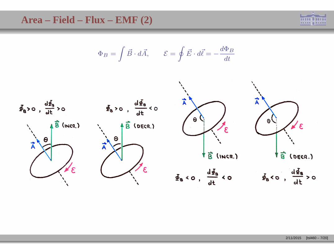
Area – Field – Flux – EMF (2)
ΦB =
Z
~B · d ~A, E =
I
~E · d~ℓ = −dΦB
dt
2/11/2015 [tsl460 – 7/20]

Magnetic Induction: Application (3)
A uniform magnetic field ~B pointing into the plane and increasing in magnitude as shown in thegraph exists inside the dashed rectangle.
• Find the magnitude (in amps) and the direction (cw/ccw) of the currents I1, I2 induced in thesmall conducting square and in the big conducting rectangle, respectively. Each conductingloop has a resistance R = 9Ω
B
2T
1st
3m
13m
B
9m
I I 3m 7m 10m2 1
2/11/2015 [tsl254 – 8/20]

Magnetic Induction: Application (4)
A magnetic field ~B of increasing strength and directed perpendicular to the plane exists inside thedashed square. It induces a constant clockwise current I = 8A in the large conducting square withresistance R = 9Ω.
• If ~B = 0 at time t = 0, find the direction (⊙,⊗) and magnitude of ~B at time t = 5s.
B I
6m
6m
2/11/2015 [tsl255 – 9/20]

Magnetic Induction: Application (5)
A uniform magnetic field ~B pointing out of the plane exists inside the dashed square. Fourconducting rectangles 1,2,3,4 move in the directions indicated.
• Find the direction (cw,ccw) of the current induced in each rectangle.
1
2
3
4
B
2/11/2015 [tsl256 – 10/20]

Magnetic Induction: Application (9)
Consider a conducting rod of length L rotating with angular velocity ω in a plane perpendicular to auniform magnetic field ~B.
• Angular velocity of slice: ω
• Linear velocity of slice: v = ωr
• EMF induced in slice: dE = Bvdr
• Slices are connected in series.
• EMF induced in rod:
E =
Z L
0
Bv dr = Bω
Z L
0
r dr
⇒ E =1
2BωL2 =
1
2BvL B
v
r
ω
drL
2/11/2015 [tsl260 – 11/20]

Lenz’s Rule (1)
The induced emf and induced currentare in such a direction as to opposethe cause that produces them.
• Lenz’s rule is a statement of negative feedback.
• The cause is a change in magnetic flux through some loop.
• The loop can be real or fictitious.
• What opposes the cause is a magnetic field generated by the induced emf.
If the loop is a conductor the opposing magnetic field is generated by the induced currentas stated in the law of Biot and Savart or in the restricted version of Ampère’s law.
If the loop is not a conductor the opposing magnetic field is generated by the inducedelectric field as stated by the extended version of Ampère’s law (to be discussed later).
2/11/2015 [tsl250 – 12/20]

Lenz’s Rule (2)
In the situation shown below the current induced in the conducting ring generates a magnetic fieldwhose flux counteracts the change in magnetic flux caused by the bar magnet.
• Moving the bar magnet closer to the ring increases the magnetic field ~B1 (solid field lines)through the ring by the amount ∆ ~B1.
• The resultant change in magnetic flux through the ring induces a current I in the directionshown.
• The induced current I, in turn, generates a magnetic field ~B2 (dashed field lines) in adirection that opposes the change of flux caused by the moving bar magnet.
2/11/2015 [tsl251 – 13/20]

AC Generator
• Area of conducting loop: A
• Number of loops: N
• Area vector: ~A = An
• Magnetic field: ~B
• Angle between vectors ~A and ~B: θ = ωt
• Magnetic flux: ΦB = N ~A · ~B = NAB cos(ωt)
• Induced EMF: E = −dΦB
dt= NABω
| z
Emax
sin(ωt)
2/11/2015 [tsl412 – 14/20]

AC Motor
• Power source produces alternating current (ac) in loop.
• Current exerts torque on loop.
• Torque initiates and maintains rotation.
• Rotating loop induces back emf (counteracting source emf).
2/11/2015 [tsl413 – 15/20]

Magnetic Induction: Application (8)
Consider a rectangular loop of width ℓ in a uniform magnetic field ~B directed into the plane. A slidewire of mass m is given an initial velocity ~v0 to the right. There is no friction between the slide wireand the loop. The resistance R of the loop is constant.
(a) Find the magnetic force on the slide wire as a function of its velocity.
(b) Find the velocity of the slide wire as a function of time.
(c) Find the total distance traveled by the slide wire.
2/11/2015 [tsl259 – 16/20]

Magnetic Induction: Application (1)
Consider three metal rods of length L = 2m moving translationally or rotationally across a uniformmagnetic field B = 1T directed into the plane.All velocity vectors have magnitude v = 2m/s.
• Find the induced EMF E between the ends of each rod.
v
v v
v
(a) (b) (c)
B B
v
2/11/2015 [tsl252 – 17/20]

Intermediate Exam III: Problem #2 (Spring ’06)
A conducting loop in the shape of a square with area A = 4m2 and resistance R = 5Ω is placed inthe yz-plane as shown. A time-dependent magnetic field B = Bx i is present. The dependence ofBx on time is shown graphically.(a) Find the magnetic flux ΦB through the loop at time t = 0.(b) Find magnitude and direction (cw/ccw) of the induced current I at time t = 2s.
2
0
3
2
1
0 4
B [T]x
t [s]
z
x
y
A
2/11/2015 [tsl356 – 18/20]

Intermediate Exam III: Problem #2 (Spring ’06)
A conducting loop in the shape of a square with area A = 4m2 and resistance R = 5Ω is placed inthe yz-plane as shown. A time-dependent magnetic field B = Bx i is present. The dependence ofBx on time is shown graphically.(a) Find the magnetic flux ΦB through the loop at time t = 0.(b) Find magnitude and direction (cw/ccw) of the induced current I at time t = 2s.
2
0
3
2
1
0 4
B [T]x
t [s]
z
x
y
A
Choice of area vector: ⊙/⊗ ⇒ positive direction = ccw/cw.
(a) ΦB = ±(1T)(4m2) = ±4Tm2.
(b)dΦB
dt= ±(0.5T/s)(4m2) = ±2V ⇒ E = −
dΦB
dt= ∓2V.
⇒ I =E
R= ∓
2V
5Ω= ∓0.4A (cw).
2/11/2015 [tsl356 – 18/20]

Intermediate Exam III: Problem #3 (Spring ’07)
A conducting frame with a moving conducting rod is located in a uniform magnetic field as shown.(a) Find the magnetic flux ΦB through the frame at the instant shown.(b) Find the induced emf E at the instant shown.(c) Find the direction (cw/ccw) of the induced current.
v = 4m/s
B = 5T
2m4m
2m
2m
2/11/2015 [tsl367 – 19/20]

Intermediate Exam III: Problem #3 (Spring ’07)
A conducting frame with a moving conducting rod is located in a uniform magnetic field as shown.(a) Find the magnetic flux ΦB through the frame at the instant shown.(b) Find the induced emf E at the instant shown.(c) Find the direction (cw/ccw) of the induced current.
v = 4m/s
B = 5T
2m4m
2m
2m
Solution:
(a) ΦB = ~A · ~B = ±(20m2)(5T) = ±100Wb.
(b) E = −dΦB
dt= ±(5T)(2m)(4m/s) = ±40V.
(c) clockwise.
2/11/2015 [tsl367 – 19/20]

Unit Exam III: Problem #3 (Spring ’09)
A pair of rails are connected by two mobile rods. A uniform magnetic field B directed into theplane is present. In the situations (a), (b), (c), (d), one or both rods move at constant velocity asshown. The resistance of the conducting loop is R = 0.2Ω in each case. Find magnitude I anddirection (cw/ccw) of the induced current in each case.
v = 3m/s4mB = 0.7T
(a)
v = 5m/s4mB = 0.7T
(b)
v = 3m/sB = 0.7T
v = 5m/s4m
(d)
v = 3m/sv = 5m/sB = 0.7T
4m
(c)
2/11/2015 [tsl397 – 20/20]

Unit Exam III: Problem #3 (Spring ’09)
A pair of rails are connected by two mobile rods. A uniform magnetic field B directed into theplane is present. In the situations (a), (b), (c), (d), one or both rods move at constant velocity asshown. The resistance of the conducting loop is R = 0.2Ω in each case. Find magnitude I anddirection (cw/ccw) of the induced current in each case.
v = 3m/s4mB = 0.7T
(a)
v = 5m/s4mB = 0.7T
(b)
v = 3m/sB = 0.7T
v = 5m/s4m
(d)
v = 3m/sv = 5m/sB = 0.7T
4m
(c)
Solution:
(a) |E| = (3m/s)(0.7T)(4m) = 8.4V, I =8.4V
0.2Ω= 42A ccw
(b) |E| = (5m/s)(0.7T)(4m) = 14V, I =14V
0.2Ω= 70A cw
(c) |E| = (5m/s − 3m/s)(0.7T)(4m) = 5.6V, I =5.6V
0.2Ω= 28A cw
(d) |E| = (5m/s + 3m/s)(0.7T)(4m) = 22.4V, I =22.4V
0.2Ω= 112A ccw
2/11/2015 [tsl397 – 20/20]