motivations, opportunities and challenges of additive manufacturing for space application
TRANSCRIPT

Motivations, Opportunities and Challenges of Additive Manufacturing for Space Application
Franck MouriauxGeneral Manager StructuresRUAG Schweiz AGRUAG SpaceDearborn, Mai 6th 2015

manf’flexibility
for free
designcomplexity
for free
designMASS
reduction
leadTIME
reduction
function integration
10.05.2015│RUAG Space│2
Why AM?
FREEDOM

SUPPLIER
10.05.2015│RUAG Space│3
PRODUCT
post-processing verification
How AM?
qualification
design analysis
PROCESS MATERIAL
10.05.2015│RUAG Space│4
WhereAM?
EVERYWHERE

10.05.2015│RUAG Space│5
SENTINEL-1

10.05.2015│RUAG Space│6
Original Design1.6kg88.7Hz163MPa
2First Optimisation Loop1.2kg88.7Hz
1
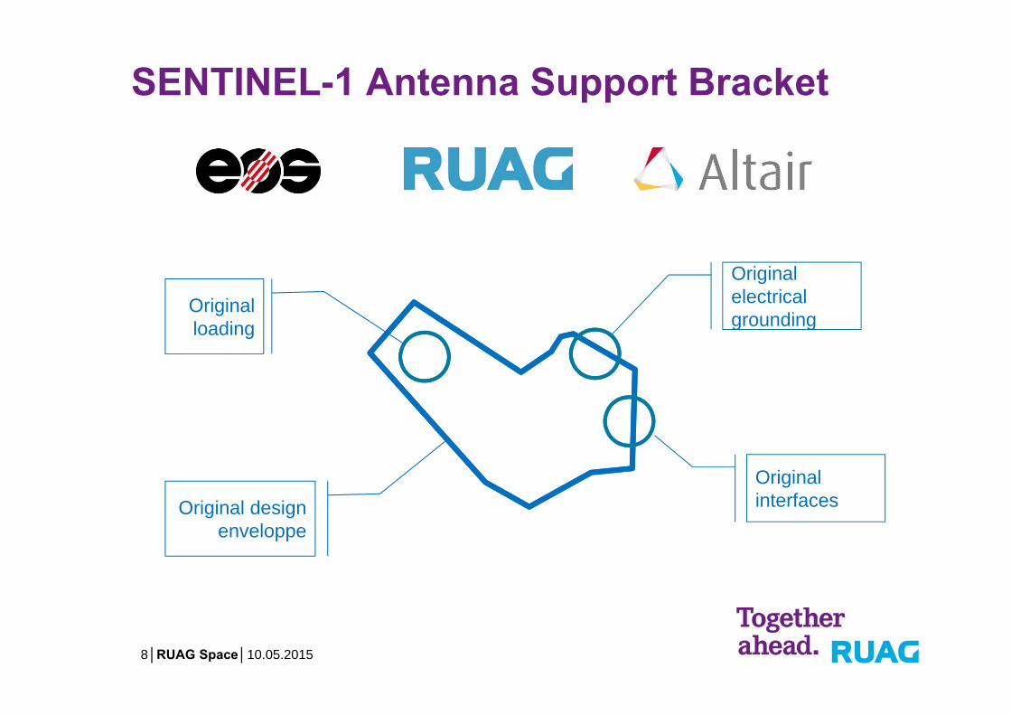
SENTINEL-1 Antenna Support Bracket

10.05.2015│RUAG Space│7
Original design enveloppe
Original interfaces
Original loading
Original electricalgrounding
SENTINEL-1 Antenna Support Bracket
10.05.2015│RUAG Space│8
Original design enveloppe
Original interfaces
Original loading
Original electricalgrounding
SENTINEL-1 Antenna Support Bracket

10.05.2015│RUAG Space│9
3Final Design0.936kg91.5Hz103MPa
SENTINEL-1 Antenna Support Bracket

10.05.2015│RUAG Space│10
Topology Optimization
Topology Loadpath
CAD interpretation
Baseline CAD Design spaceLoad Cases
Optimisation loops
Model Preparation
Concept Optimis.
ConceptInterpret.
ConceptDesign
DetailedOptimis.
DetailedVerif.
Additive Manf’

10.05.2015│RUAG Space│11
• Understand where to start• Definition of design space• Definition of load cases• Definition of material
Model Preparation
Concept Optimis.
Concept Interpret.
Concept Design
Detailed Optimis.
Stress Verif.
Additive Manf’

10.05.2015│RUAG Space│12
Optimization problem formulation:• Objective: Minimize Mass OR Compliance• Constrains: Vol. frac. / Stress / Freq / Manf’• Variables: Element densities
Model Preparation
ConceptOptimis.
ConceptInterpret.
ConceptDesign
DetailedOptimis.
Stress Verif.
Additive Manf’

10.05.2015│RUAG Space│13
Model Preparation
Concept Optimis.
ConceptInterpret. 4 5 6 7
• Obtained topology must be realized into a proper CAD design
• Understand and apply design principles from AM• Printing orientation• Overhang angle consideration• Heat dissipation and stress concentration• Post-processing consideration
• Understand results from optimization• Observe similarities• Identify primary and secondary load paths?• Cross sections geometries depending on
structural behaviour

10.05.2015│RUAG Space│14
Model Preparation
Concept Optimis.
ConceptInterpret.
ConceptDesign 5 6 7
Loadpath from topology iterations interpretated as CAD modelwith Solidthinking® Evolve.

10.05.2015│RUAG Space│15
Model Preparation
Concept Optimis.
ConceptInterpret.
ConceptDesign
DetailedOptimis. 6 7
Shear web could be replaced with cross members
Cross member could be discarded
• Many sections highlighted proved to be redundant after incorporating mounting interfaces.
• Findings from Loop2 topology iterations implemented in the new CAD

10.05.2015│RUAG Space│16
Model Preparation
Concept Optimis.
ConceptInterpret.
ConceptDesign
DetailedOptimis.
DetailedVerif. 7
Dynamic Verification
Static Strength Verification

10.05.2015│RUAG Space│17
Model Preparation
Concept Optimis.
ConceptInterpret.
ConceptDesign
DetailedOptimis.
DetailedVerif.
Additive Manf’
The parts printed from an EOS M400 from the company CITIM.
Material: AlSi10Mg (AA357-AA359 casting alloy)

10.05.2015│RUAG Space│18
Geometrical verification
Modal verification
Quasi-static load test
Sine vibration tests (3-dir.)
Random vibration tests (3-dir.)
Vibration Test
Geometrical verification
Modal verification
Quasi-static load test
Qualification Flight
Model Philosophy

10.05.2015│RUAG Space│19
Comparison of QM geometry with CAD model and identification of deviation.
Computer tomography scan with resolution of 320m
Verification

10.05.2015│RUAG Space│20
Test specimens were printed within the same print job as the two S1 AM brackets.
Verification
10.05.2015│RUAG Space│21
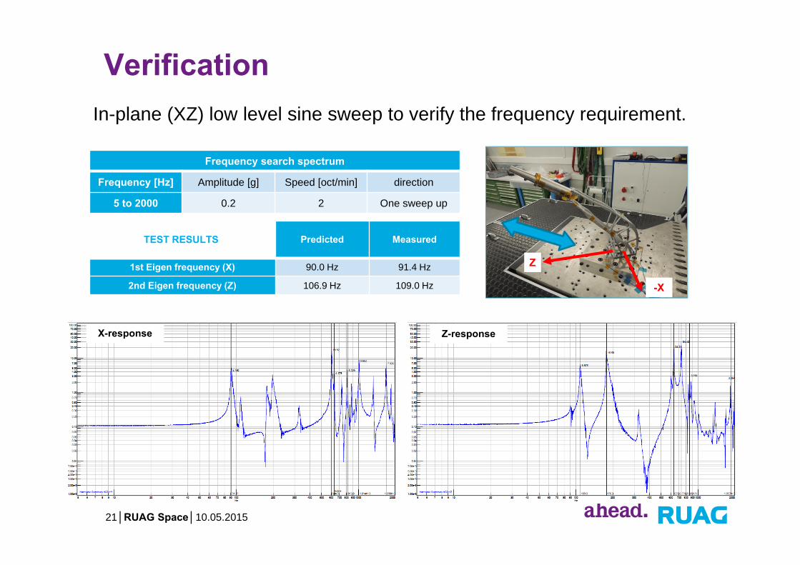
In-plane (XZ) low level sine sweep to verify the frequency requirement.
Frequency search spectrum
Frequency [Hz] Amplitude [g] Speed [oct/min] direction
5 to 2000 0.2 2 One sweep up
TEST RESULTS Predicted Measured
1st Eigen frequency (X) 90.0 Hz 91.4 Hz
2nd Eigen frequency (Z) 106.9 Hz 109.0 Hz -X
Z
X-response Z-response
Verification

10.05.2015│RUAG Space│22
Out-of-plane (Y) low level sine sweep to verify the frequency requirement.
Y
TEST RESULTS Predicted Measured
1st Eigen frequency 106.9 Hz 107.8 Hz
Verification
10.05.2015│RUAG Space│23
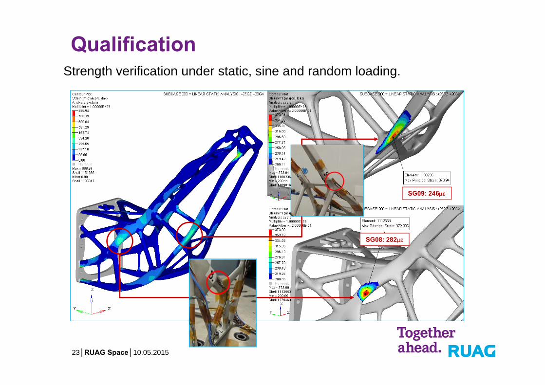
SG08: 282
SG09: 246
Strength verification under static, sine and random loading.
Qualification

10.05.2015│RUAG Space│24
Qualification

10.05.2015│RUAG Space│25
TopologyOptimisation
Design / Optimisation Manufacturing Verification / Testing
Functional analysis
Topology optimisation
CAD Interpretation
Size/Shape Optimisation
Detail Stressing
Optimisation
Post-Processing
Samples Definition
Process Control
Quality Control
Test Definition
Qualification Testing
Model Correlation
CAD Interpretation
Manufacturing Verification Testing
Additive Manufacturing Development Process

Main Challenges…
Acceptance of the technology by customers and authorities
Qualification and control of the materials and processes
Development of additive manufacturing technologies
Development of new engineering thinking
Development of new design tools
Acceptance
Qualification
Development
Development
Development
10.05.2015│RUAG Space│26

AM in Space…more than a hype!
10.05.2015│RUAG Space│27
"My goal is to have over 50% of the structures 3-D-printed within two to three years,"
Richard Ambrose, executive vice president ofDenver-based Lockheed Martin SpaceSystemsJul 24, 2014
Lockheed Martin Testing 3-D-Printed Subsystems On A2100 Space Bus | AWINONLY content from Aviation Week
Lockheed Martin Testing 3-D-Printed Subsystems On A2100Space Bus
10.05.2015│RUAG Space│28
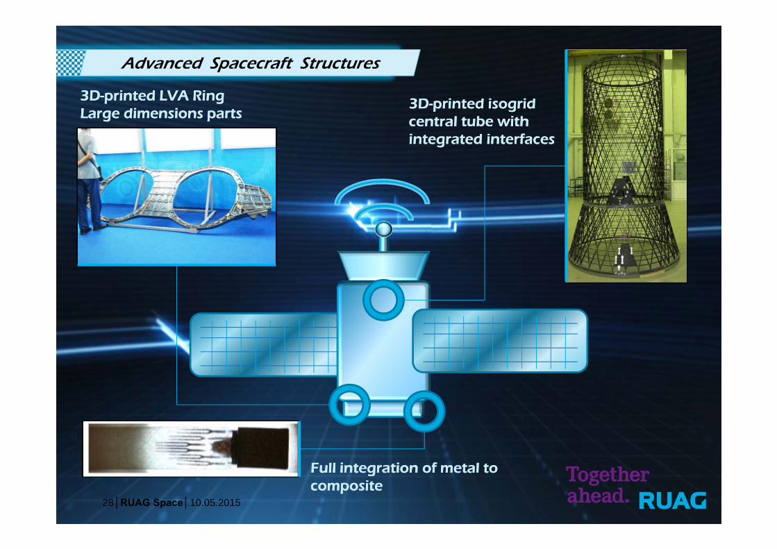
Advanced Spacecraft Structures
3D-printed LVA RingLarge dimensions parts3D-printed LVA RingLarge dimensions parts
Full integration of metal tocompositeFull integration of metal tocomposite
3D-printed isogridcentral tube withintegrated interfaces
3D-printed isogridcentral tube withintegrated interfaces

10.05.2015│RUAG Space│29
Advanced Spacecraft Structures
Integrated high power 3D-printed heatpipesIntegrated high power 3D-printed heatpipes
Integrated metal coatedplastic 3D-printed wave-guides
Integrated metal coatedplastic 3D-printed wave-guides
Surface printedelectrical circuitsSurface printedelectrical circuits
Thermo-opticalsurface coatingThermo-opticalsurface coating

10.05.2015│RUAG Space│30
Advanced Spacecraft Structures
Lightweight 3D-printed brackets with adaptive stiffness and damping
Lightweight 3D-printed brackets with adaptive stiffness and damping
Thin plies CFRP sandwichwith ultralight 3D-printed core with anti-telegrahingfeature
Thin plies CFRP sandwichwith ultralight 3D-printed core with anti-telegrahingfeature
High efficiency 3D-printed solar cellsHigh efficiency 3D-printed solar cells

10.05.2015│RUAG Space│31
Advanced Spacecraft Structures

Thank you for your attention!
10.05.2015│RUAG Space│32
Franck MouriauxGeneral Manager Structures
RUAG Schweiz AGRUAG SpaceSchaffhauserstrasse 5808052 Zürich · Switzerland
Tel. +41 44 306 21 37Fax. +41 44 306 27 50Mobile: +41 78 709 56 [email protected]://www.ruag.com