motor control starter kit user’s...
TRANSCRIPT
© 2011 Microchip Technology Inc. DS75015A
Motor Control Starter KitUser’s Guide
Note the following details of the code protection feature on Microchip devices:• Microchip products meet the specification contained in their particular Microchip Data Sheet.
• Microchip believes that its family of products is one of the most secure families of its kind on the market today, when used in the intended manner and under normal conditions.
• There are dishonest and possibly illegal methods used to breach the code protection feature. All of these methods, to our knowledge, require using the Microchip products in a manner outside the operating specifications contained in Microchip’s Data Sheets. Most likely, the person doing so is engaged in theft of intellectual property.
• Microchip is willing to work with the customer who is concerned about the integrity of their code.
• Neither Microchip nor any other semiconductor manufacturer can guarantee the security of their code. Code protection does not mean that we are guaranteeing the product as “unbreakable.”
Code protection is constantly evolving. We at Microchip are committed to continuously improving the code protection features of ourproducts. Attempts to break Microchip’s code protection feature may be a violation of the Digital Millennium Copyright Act. If such actsallow unauthorized access to your software or other copyrighted work, you may have a right to sue for relief under that Act.
Information contained in this publication regarding deviceapplications and the like is provided only for your convenienceand may be superseded by updates. It is your responsibility toensure that your application meets with your specifications.MICROCHIP MAKES NO REPRESENTATIONS ORWARRANTIES OF ANY KIND WHETHER EXPRESS ORIMPLIED, WRITTEN OR ORAL, STATUTORY OROTHERWISE, RELATED TO THE INFORMATION,INCLUDING BUT NOT LIMITED TO ITS CONDITION,QUALITY, PERFORMANCE, MERCHANTABILITY ORFITNESS FOR PURPOSE. Microchip disclaims all liabilityarising from this information and its use. Use of Microchipdevices in life support and/or safety applications is entirely atthe buyer’s risk, and the buyer agrees to defend, indemnify andhold harmless Microchip from any and all damages, claims,suits, or expenses resulting from such use. No licenses areconveyed, implicitly or otherwise, under any Microchipintellectual property rights.
DS75015A-page 2
Trademarks
The Microchip name and logo, the Microchip logo, dsPIC, KEELOQ, KEELOQ logo, MPLAB, PIC, PICmicro, PICSTART, PIC32 logo, rfPIC and UNI/O are registered trademarks of Microchip Technology Incorporated in the U.S.A. and other countries.
FilterLab, Hampshire, HI-TECH C, Linear Active Thermistor, MXDEV, MXLAB, SEEVAL and The Embedded Control Solutions Company are registered trademarks of Microchip Technology Incorporated in the U.S.A.
Analog-for-the-Digital Age, Application Maestro, chipKIT, chipKIT logo, CodeGuard, dsPICDEM, dsPICDEM.net, dsPICworks, dsSPEAK, ECAN, ECONOMONITOR, FanSense, HI-TIDE, In-Circuit Serial Programming, ICSP, Mindi, MiWi, MPASM, MPLAB Certified logo, MPLIB, MPLINK, mTouch, Omniscient Code Generation, PICC, PICC-18, PICDEM, PICDEM.net, PICkit, PICtail, REAL ICE, rfLAB, Select Mode, Total Endurance, TSHARC, UniWinDriver, WiperLock and ZENA are trademarks of Microchip Technology Incorporated in the U.S.A. and other countries.
SQTP is a service mark of Microchip Technology Incorporated in the U.S.A.
All other trademarks mentioned herein are property of their respective companies.
© 2011, Microchip Technology Incorporated, Printed in the U.S.A., All Rights Reserved.
Printed on recycled paper.
ISBN: 978-1-61341-318-0
© 2011 Microchip Technology Inc.
Microchip received ISO/TS-16949:2002 certification for its worldwide headquarters, design and wafer fabrication facilities in Chandler and Tempe, Arizona; Gresham, Oregon and design centers in California and India. The Company’s quality system processes and procedures are for its PIC® MCUs and dsPIC® DSCs, KEELOQ® code hopping devices, Serial EEPROMs, microperipherals, nonvolatile memory and analog products. In addition, Microchip’s quality system for the design and manufacture of development systems is ISO 9001:2000 certified.
MOTOR CONTROL STARTERKIT USER’S GUIDE
Table of Contents
Chapter 1. Introduction1.1 Kit Contents .................................................................................................. 111.2 Electrical Specifications ................................................................................ 121.3 Starter Kit Functionality and Features .......................................................... 12
Chapter 2. Software Description2.1 Motor Control Application ............................................................................. 152.2 mTouch Capacitive Slider Application .......................................................... 152.3 Integrating Motor Control and mTouch ......................................................... 16
Chapter 3. Hardware3.1 Programmer/Debugger ................................................................................. 183.2 Signal Configuration ..................................................................................... 193.3 Programmer/Debugger Components ........................................................... 203.4 Application Components .............................................................................. 203.5 Board Connectors ........................................................................................ 213.6 Indicators and Human Interfaces ................................................................. 223.7 Test Points ................................................................................................... 22
Appendix A. Layout, Schematics, and Bill of MaterialsA.1 Starter Kit Board Layout ............................................................................... 23A.2 Debugger Hardware Schematics ................................................................. 25A.3 Application Schematics ................................................................................ 26
© 2011 Microchip Technology Inc. DS75015A-page 3

Motor Control Starter Kit User’s Guide
NOTES:
DS75015A-page 4 © 2011 Microchip Technology Inc.
MOTOR CONTROL STARTER
KIT USER’S GUIDEPreface
INTRODUCTIONThis chapter contains general information that will be useful to know before you use the Motor Control Starter Kit. Items discussed in this Preface include:• Document Layout• Conventions Used in this Guide• Warranty Registration• Recommended Reading• The Microchip Web Site• Development Systems Customer Change Notification Service• Customer Support• Document Revision History
DOCUMENT LAYOUTThis document describes how to use one of the starter kits as a development tool to emulate and debug firmware on a target board. The document layout is as follows:• Chapter 1. “Introduction” – This chapter provides a brief overview of the Motor Control
Starter Kit.• Chapter 2. “Software Description” – This chapter describes the software that is provided
with the Motor Control Starter Kit.• Chapter 3. “Hardware” – This chapter describes the Motor Control Starter Kit hardware.• Appendix A. “Layout, Schematics, and Bill of Materials” – This appendix provides
detailed schematics, board layout, and the bill of materials for the Motor Control Starter Kit.
NOTICE TO CUSTOMERS
All documentation becomes dated, and this manual is no exception. Microchip tools and documentation are constantly evolving to meet customer needs, so some actual dialogs and/or tool descriptions may differ from those in this document. Please refer to our web site (www.microchip.com) to obtain the latest documentation available.Documents are identified with a “DS” number. This number is located on the bottom of each page, in front of the page number. The numbering convention for the DS number is “DSXXXXXA”, where “XXXXX” is the document number and “A” is the revision level of the document.For the most up-to-date information on development tools, see the MPLAB® IDE online help. Select the Help menu, and then Topics to open a list of available online help files.
© 2011 Microchip Technology Inc. DS75015A-page 5
Motor Control Starter Kit User’s Guide
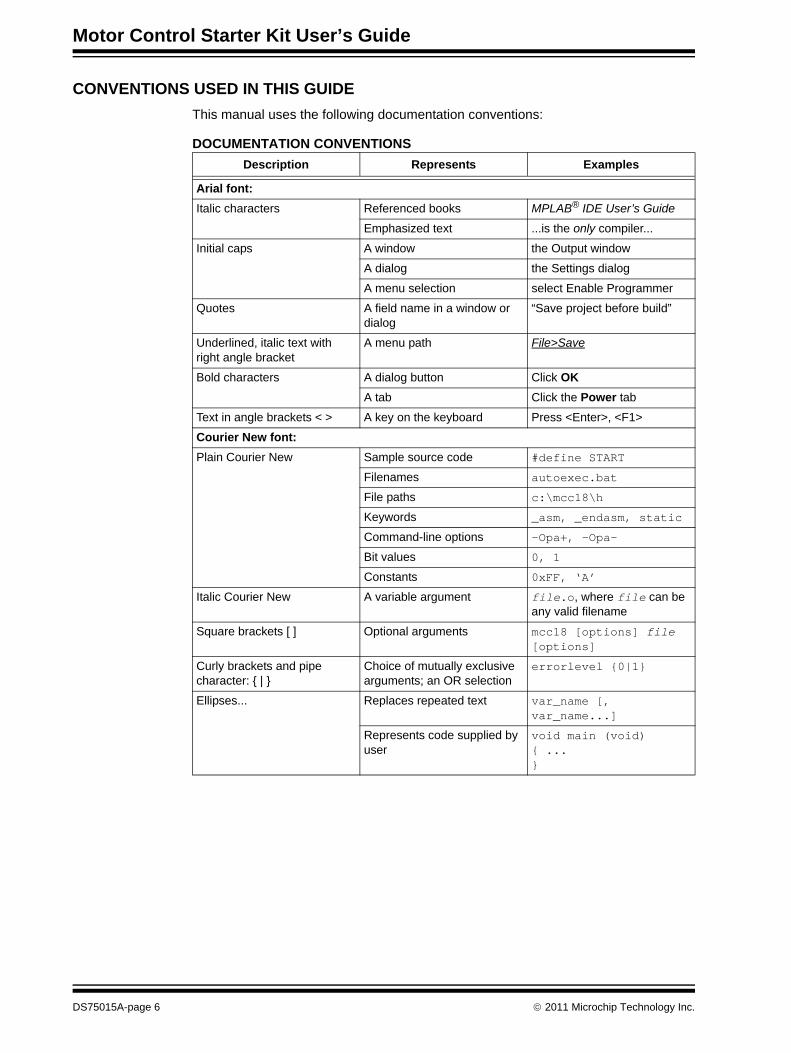
CONVENTIONS USED IN THIS GUIDEThis manual uses the following documentation conventions:
DOCUMENTATION CONVENTIONSDescription Represents Examples
Arial font:Italic characters Referenced books MPLAB® IDE User’s Guide
Emphasized text ...is the only compiler...
Initial caps A window the Output window
A dialog the Settings dialog
A menu selection select Enable Programmer
Quotes A field name in a window or dialog
“Save project before build”
Underlined, italic text with right angle bracket
A menu path File>Save
Bold characters A dialog button Click OKA tab Click the Power tab
Text in angle brackets < > A key on the keyboard Press <Enter>, <F1>
Courier New font:Plain Courier New Sample source code #define START
Filenames autoexec.bat
File paths c:\mcc18\h
Keywords _asm, _endasm, static
Command-line options -Opa+, -Opa-
Bit values 0, 1
Constants 0xFF, ‘A’
Italic Courier New A variable argument file.o, where file can be any valid filename
Square brackets [ ] Optional arguments mcc18 [options] file [options]
Curly brackets and pipe character: { | }
Choice of mutually exclusive arguments; an OR selection
errorlevel {0|1}
Ellipses... Replaces repeated text var_name [, var_name...]
Represents code supplied by user
void main (void){ ...}
DS75015A-page 6 © 2011 Microchip Technology Inc.
Preface
WARRANTY REGISTRATIONPlease complete the enclosed Warranty Registration Card and mail it promptly. Sending in the Warranty Registration Card entitles you to receive new product updates. Interim software releases are available at the Microchip web site.
RECOMMENDED READINGThis user’s guide describes how to use the Motor Control Starter Kit. The following are available and recommended as supplemental reference resources.
BLDC Motor Control Resources• AN1160 “Sensorless BLDC motor control using a Majority Function”• AN901 “Using the dsPIC30F for Sensorless BLDC Control”• AN885 “Brushless DC (BLDC) Motor Fundamentals”• AN857 “Brushless DC Motor Control Made Easy”• Web Seminar – “Sensorless BLDC Motor Control Using a Majority Function”
mTouch Resources• AN1250 “Microchip CTMU for Capacitive Touch Applications”• Web Seminar – “Introduction to mTouch™ Capacitive Touch Sensing”
You can obtain these reference documents as well as other related documents from your nearest Microchip sales office (listed in the back of this document) or by downloading them from the Microchip web site (www.microchip.com) at the following locations:• http://www.microchip.com/appnotes/• http://techtrain.microchip.com/webseminars/QuickList.aspx• http://www.microchip.com/motor/• http://www.microchip.com/mtouch/
dsPIC33FJ16GP101/102 and dsPIC33FJ16MC101/102 Data Sheet (DS70652)Refer to this document for detailed information on this family of dsPIC33F General Purpose and Motor Control Digital Signal Controllers (DSC). Reference information found in this data sheet includes:• Device memory maps• Device pinout and packaging details• Device electrical specifications• List of peripherals included on the devices
dsPIC33F/PIC24H Family Reference Manual SectionsFamily Reference Manual sections are available, which explain the operation of the dsPIC® DSC family architecture and peripheral modules. The specifics of each device family are discussed in the individual family’s device data sheet.
dsPIC33F/PIC24H Flash Programming Specification (DS70152)Refer to this document for information on instruction sets and firmware development. This document may be obtained from the Microchip web site or your local sales office.
© 2011 Microchip Technology Inc. DS75015A-page 7
Motor Control Starter Kit User’s Guide
MPLAB® C Compiler for PIC24 MCUs and dsPIC® DSCs User’s Guide (DS51284)This document details the use of Microchip’s MPLAB C Compiler for PIC24 MCUs and dsPIC DSC devices to develop an application. The MPLAB C Compiler is a GNU-based language tool, based on source code from the Free Software Foundation (FSF). For more information about the FSF, visit www.fsf.org.
MPLAB® IDE User’s Guide (DS51519)This document describes how to use the MPLAB IDE Integrated Development Environ-ment (IDE), as well as the MPLAB project manager, MPLAB editor and MPLAB SIM simulator. Use these development tools to help you develop and debug application code.
THE MICROCHIP WEB SITEMicrochip provides online support via our web site at www.microchip.com. This web site is used as a means to make files and information easily available to customers. Accessible by using your favorite Internet browser, the web site contains the following information:• Product Support – Data sheets and errata, application notes and sample programs,
design resources, user’s guides and hardware support documents, latest software releases and archived software
• General Technical Support – Frequently Asked Questions (FAQs), technical support requests, online discussion groups, Microchip consultant program member listing
• Business of Microchip – Product selector and ordering guides, latest Microchip press releases, listing of seminars and events, listings of Microchip sales offices, distributors and factory representatives
DEVELOPMENT SYSTEMS CUSTOMER CHANGE NOTIFICATION SERVICEMicrochip’s customer notification service helps keep customers current on Microchip products. Subscribers will receive e-mail notification whenever there are changes, updates, revisions or errata related to a specified product family or development tool of interest.To register, access the Microchip web site at www.microchip.com, click on Customer Change Notification and follow the registration instructions.The Development Systems product group categories are:• Compilers – The latest information on Microchip C compilers and other language tools.
These include the MPLAB® C compiler; MPASM™ and MPLAB 16-bit assemblers; MPLINK™ and MPLAB 16-bit object linkers; and MPLIB™ and MPLAB 16-bit object librari-ans.
• Emulators – The latest information on the Microchip in-circuit emulator, MPLAB REAL ICE™
• In-Circuit Debuggers – The latest information on the Microchip in-circuit debugger, MPLAB ICD 3.
• MPLAB IDE – The latest information on Microchip MPLAB IDE, the Windows® Integrated Development Environment for development systems tools. This list is focused on the MPLAB IDE, MPLAB SIM simulator, MPLAB IDE Project Manager and general editing and debugging features.
• Programmers – The latest information on Microchip programmers. These include the MPLAB PM3 device programmer and the PICkit™ 3 development programmers.
DS75015A-page 8 © 2011 Microchip Technology Inc.
Preface
CUSTOMER SUPPORTUsers of Microchip products can receive assistance through several channels:• Distributor or Representative• Local Sales Office• Field Application Engineer (FAE)• Technical Support
Customers should contact their distributor, representative or field application engineer (FAE) for support. Local sales offices are also available to help customers. A listing of sales offices and locations is included in the back of this document.Technical support is available through the web site at: http://www.microchip.com/support
DOCUMENT REVISION HISTORY
Revision A (June 2011)This is the initial released version of the document.
© 2011 Microchip Technology Inc. DS75015A-page 9
Motor Control Starter Kit User’s Guide
NOTES:
DS75015A-page 10 © 2011 Microchip Technology Inc.
MOTOR CONTROL STARTER
KIT USER’S GUIDEChapter 1. Introduction
Thank you for purchasing a Motor Control Starter Kit from Microchip Technology. The board provided in the kit is intended to introduce and demonstrate the capabilities and features of the low-cost 16-bit Motor Control and mTouch™ families of devices. In addition, the Motor Control Starter Kit includes an on-board programmer/debugger, which eliminates the need for an additional programmer or hardware interface.This chapter introduces thes Motor Control Starter Kit and provides an overview of its features. Topics covered include:• Kit Contents• Electrical Specifications• Starter Kit Functionality and Features
The software for the demonstration application that is preprogrammed into the on-board dsPIC33F Digital Signal Controller (DSC) is available for download from the Microchip web site at: http://www.microchip.com.All project files have been included so that the code may be used directly to restore the dsPIC33F DSC on the starter kit to its original state (i.e., if the sample device has been reprogrammed with another program) or so you can use the demonstration code as a platform for further experiment and evaluation.
1.1 KIT CONTENTSThe Motor Control Starter Kit contains the following:• Motor Control Starter Kit Board • BLDC motor• 9V power supply• USB cable
Note: Refer to the Readme file provided with the Motor Control Starter Kit demonstrationsoftware for instructions on how to run the demonstration application. Refer to theInformation Sheet that is provided with the starter kit package for additionalresources and instructions on how to use the starter kit for programming and debug-ging application software.
Note: If you are missing any part of a kit, contact a Microchip sales office for assistance. Alist of worldwide Microchip offices for sales and service is provided at the end of thisdocument.
© 2011 Microchip Technology Inc. DS75015A-page 11
Motor Control Starter Kit User’s Guide
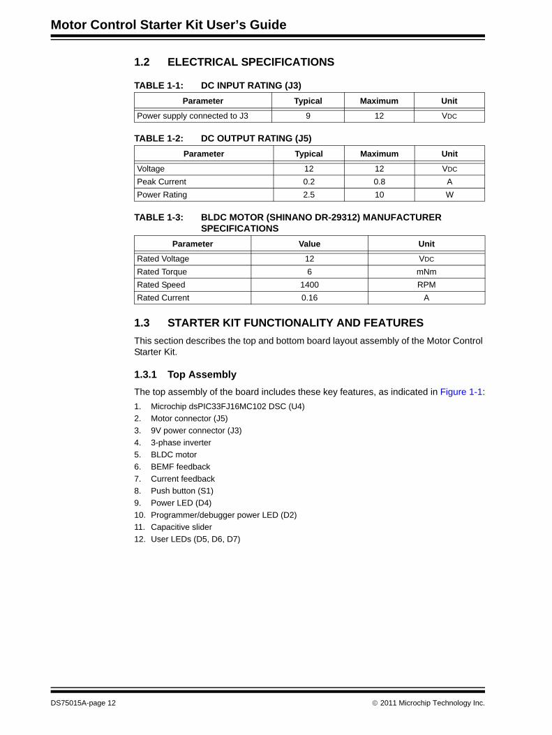
1.2 ELECTRICAL SPECIFICATIONS
TABLE 1-1: DC INPUT RATING (J3)
TABLE 1-2: DC OUTPUT RATING (J5)
TABLE 1-3: BLDC MOTOR (SHINANO DR-29312) MANUFACTURER SPECIFICATIONS
1.3 STARTER KIT FUNCTIONALITY AND FEATURESThis section describes the top and bottom board layout assembly of the Motor Control Starter Kit.
1.3.1 Top AssemblyThe top assembly of the board includes these key features, as indicated in Figure 1-1:1. Microchip dsPIC33FJ16MC102 DSC (U4)2. Motor connector (J5)3. 9V power connector (J3)4. 3-phase inverter5. BLDC motor6. BEMF feedback7. Current feedback8. Push button (S1)9. Power LED (D4)10. Programmer/debugger power LED (D2)11. Capacitive slider12. User LEDs (D5, D6, D7)
Parameter Typical Maximum Unit
Power supply connected to J3 9 12 VDC
Parameter Typical Maximum Unit
Voltage 12 12 VDC
Peak Current 0.2 0.8 APower Rating 2.5 10 W
Parameter Value Unit
Rated Voltage 12 VDC
Rated Torque 6 mNmRated Speed 1400 RPMRated Current 0.16 A
DS75015A-page 12 © 2011 Microchip Technology Inc.
Introduction
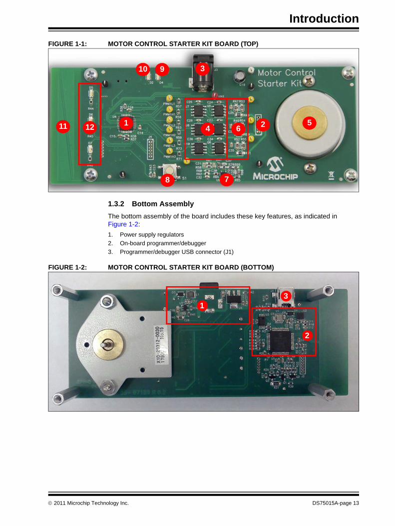
FIGURE 1-1: MOTOR CONTROL STARTER KIT BOARD (TOP)
1.3.2 Bottom AssemblyThe bottom assembly of the board includes these key features, as indicated in Figure 1-2:1. Power supply regulators2. On-board programmer/debugger3. Programmer/debugger USB connector (J1)
FIGURE 1-2: MOTOR CONTROL STARTER KIT BOARD (BOTTOM)
1 2
3
45
6
78
910
11 12
13
2
© 2011 Microchip Technology Inc. DS75015A-page 13

Motor Control Starter Kit User’s Guide
NOTES:
DS75015A-page 14 © 2011 Microchip Technology Inc.
MOTOR CONTROL STARTER
KIT USER’S GUIDEChapter 2. Software Description
The starter kit tutorial application demonstrates how to successfully integrate a noise sensitive mTouch application within a standard Motor Control environment.This chapter contains the following topics:• Motor Control Application• mTouch Capacitive Slider Application• Integrating Motor Control and mTouch
2.1 MOTOR CONTROL APPLICATIONThe motor control software and hardware on this starter kit are based on the algorithm described in the application note, AN1160 “Sensorless BLDC Control with Back-EMF Filtering Using a Majority Function”, which is available from the Microchip website (www.microchip.com).The main difference from the standard AN1160 software is the way the overcurrent fault functionality is implemented. The dsPIC33FJ16MC102 DSC features an internal ana-log comparator, which allows instant detection of an overcurrent condition and imme-diate hardware shutdown of the PWM outputs. The overcurrent level can be easily set in software, thus making the solution much more flexible and adaptable to a wide range of motors. The motor current that passes through a shunt, is amplified by an operational amplifier and is available as input on an analog pin of the dsPIC33FJ16MC102 DSC. The analog input can be configured in software both as a comparator input and as an ADC input. Reading the current with the ADC module offers the possibility of implementing more complex control algorithms, such as the single shunt.To close the Fault detection loop, the comparator output is wired externally to the PWM Fault input. As soon as the current exceeds the level set in software, the comparator will toggle its output and the PWM will be shut down immediately, without waiting for the next clock pulse to occur.
2.2 mTouch CAPACITIVE SLIDER APPLICATIONThe capacitive slider on the Motor Control Starter Kit is implemented based on the application note, AN1250 “Microchip CTMU for Capacitive Touch Applications”. For detailed information on mTouch sliders and buttons, and the CTMU module, refer to this document, which is available from the Microchip website (www.microhip.com).A two-channel capacitive slider is implemented on the Motor Control Starter Kit. Each channel is connected to an analog input on the dsPIC33FJ16MC102 DSC. The CTMU module charges each channel’s capacitance with a fixed current for a certain amount of time. The capacitance of each channel depends on the position of the user’s finger over the slider, and it is at its higher value when the slider is not touched. After the fixed charging time has elapsed, the CTMU module stops charging the capacitors and trig-gers the ADC to start sampling and converting the voltage on each capacitor to a numerical value.
© 2011 Microchip Technology Inc. DS75015A-page 15
Motor Control Starter Kit User’s Guide
The numerical value for each channel is filtered to remove noise, and then, based on predefined thresholds, the position of the user’s finger on the slider is determined. Movements over the slider can also be detected by monitoring both channels over a period of time.
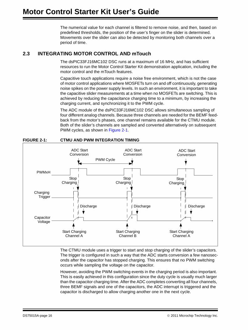
2.3 INTEGRATING MOTOR CONTROL AND mTouchThe dsPIC33FJ16MC102 DSC runs at a maximum of 16 MHz, and has sufficient resources to run the Motor Control Starter Kit demonstration application, including the motor control and the mTouch features.Capacitive touch applications require a noise free environment, which is not the case of motor control applications where MOSFETs turn on and off continuously, generating noise spikes on the power supply levels. In such an environment, it is important to take the capacitive slider measurements at a time when no MOSFETs are switching. This is achieved by reducing the capacitance charging time to a minimum, by increasing the charging current, and synchronizing it to the PWM cycle. The ADC module of the dsPIC33FJ16MC102 DSC allows simultaneous sampling of four different analog channels. Because three channels are needed for the BEMF feed-back from the motor’s phases, one channel remains available for the CTMU module. Both of the slider’s channels are sampled and converted alternatively on subsequent PWM cycles, as shown in Figure 2-1.
FIGURE 2-1: CTMU AND PWM INTEGRATION TIMING
The CTMU module uses a trigger to start and stop charging of the slider’s capacitors. The trigger is configured in such a way that the ADC starts conversion a few nanosec-onds after the capacitor has stopped charging. This ensures that no PWM switching occurs while sampling the voltage on the capacitor. However, avoiding the PWM switching events in the charging period is also important. This is easily achieved in this configuration since the duty cycle is usually much larger than the capacitor charging time. After the ADC completes converting all four channels, three BEMF signals and one of the capacitors, the ADC interrupt is triggered and the capacitor is discharged to allow charging another one in the next cycle.
PWM Cycle
PWMxH
Charging Trigger
Capacitor
ADC Start Conversion
ADC Start Conversion
ADC Start Conversion
Start Charging Channel A
Stop
Start Charging Channel B
Stop
Start Charging Channel A
Stop
Discharge Discharge Discharge
Voltage
Charging Charging Charging
DS75015A-page 16 © 2011 Microchip Technology Inc.
MOTOR CONTROL STARTER
KIT USER’S GUIDEChapter 3. Hardware
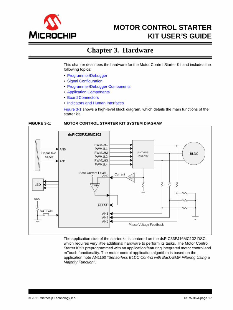
This chapter describes the hardware for the Motor Control Starter Kit and includes the following topics:• Programmer/Debugger• Signal Configuration• Programmer/Debugger Components• Application Components• Board Connectors• Indicators and Human InterfacesFigure 3-1 shows a high-level block diagram, which details the main functions of the starter kit.
FIGURE 3-1: MOTOR CONTROL STARTER KIT SYSTEM DIAGRAM
The application side of the starter kit is centered on the dsPIC33FJ16MC102 DSC, which requires very little additional hardware to perform its tasks. The Motor Control Starter Kit is preprogrammed with an application featuring integrated motor control and mTouch functionality. The motor control application algorithm is based on the application note AN1160 “Sensorless BLDC Control with Back-EMF Filtering Using a Majority Function”.
3-Phase Inverter
Safe Current Level
BLDC
BUTTON
Current
FLTA1
VDD
CMP
PWM1H1PWM1L1PWM1H2PWM1L2PWM1H3PWM1L4
AMP
AN3AN4AN5
dsPIC33FJ16MC102
CapacitiveSlider
AN0
AN1
Phase Voltage Feedback
AN2
LED
© 2011 Microchip Technology Inc. DS75015A-page 17
Motor Control Starter Kit User’s Guide
The powerful PWM module allows easy control over the 3-phase BLDC motor. The PWM module features three complementary output pairs, hardware Fault shutdown, programmable dead time, among others. A standard 3-phase inverter is used to interface the device and the motor. Three ADC channels provide information of the motor’s BEMF by reading the voltage on the motor windings. Three resistor networks scale the voltage in the range needed by the ADC module.A single-shunt topology is featured on this starter kit, which can be used for overcurrent protection or for a single-shunt control algorithm. The dsPIC33FJ16MC102 DSC also features three analog comparators. One internal comparator is used to trigger the Fault function of the PWM module if an overcurrent. The advantage of the internal comparator is that different software thresholds can be used to implement overcurrent conditions on different motors.The demonstration application accepts user inputs from two sources: the capacitive slider, and the push button (S1). The device’s CTMU module works together with the A/D Converter to sample and convert both the channels of the capacitive slider. Three user LEDs are also available for various display combinations.The 9V power supply provided with the kit is sufficient for running the demonstration application in Stand-alone mode. In Debug mode, both the 9V power supply and the USB connection must be used.
3.1 PROGRAMMER/DEBUGGERThe Motor Control Starter Kit includes an on-board programmer/debugger circuit that provides connectivity over USB. This circuit is hard-wired to the dsPIC device to provide ICSP™ debugging/programming capability.
DS75015A-page 18 © 2011 Microchip Technology Inc.
Hardware
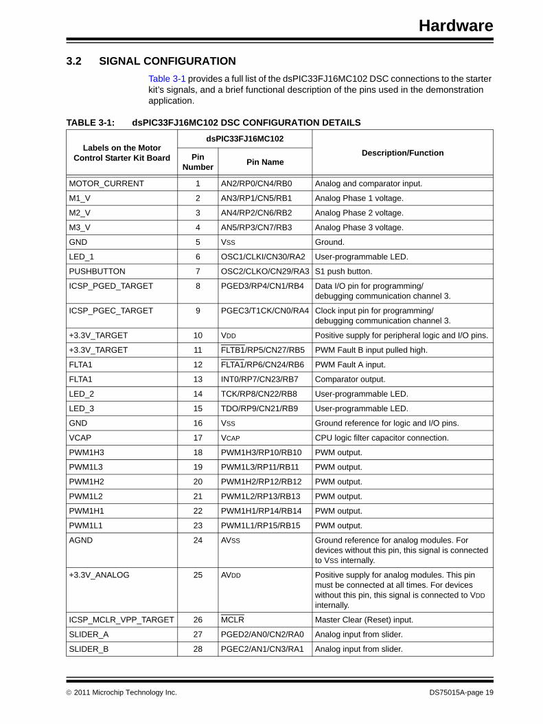
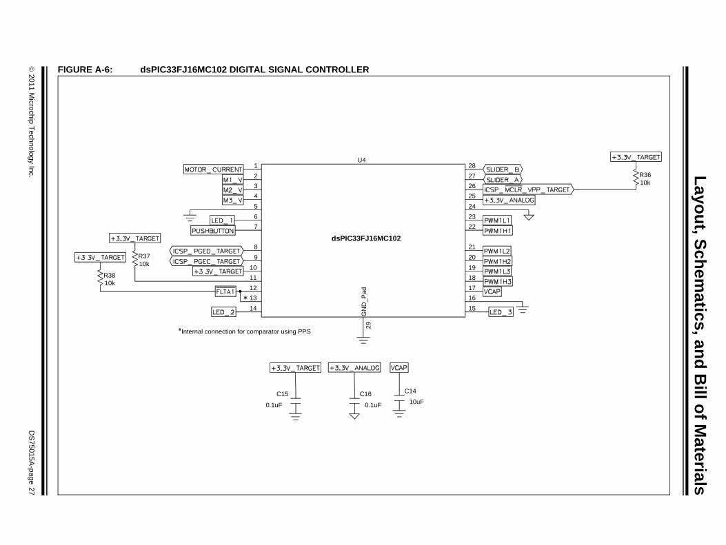
3.2 SIGNAL CONFIGURATIONTable 3-1 provides a full list of the dsPIC33FJ16MC102 DSC connections to the starter kit’s signals, and a brief functional description of the pins used in the demonstration application.
TABLE 3-1: dsPIC33FJ16MC102 DSC CONFIGURATION DETAILS
Labels on the Motor Control Starter Kit Board
dsPIC33FJ16MC102Description/FunctionPin
Number Pin Name
MOTOR_CURRENT 1 AN2/RP0/CN4/RB0 Analog and comparator input.
M1_V 2 AN3/RP1/CN5/RB1 Analog Phase 1 voltage.
M2_V 3 AN4/RP2/CN6/RB2 Analog Phase 2 voltage.
M3_V 4 AN5/RP3/CN7/RB3 Analog Phase 3 voltage.
GND 5 VSS Ground.
LED_1 6 OSC1/CLKI/CN30/RA2 User-programmable LED.
PUSHBUTTON 7 OSC2/CLKO/CN29/RA3 S1 push button.
ICSP_PGED_TARGET 8 PGED3/RP4/CN1/RB4 Data I/O pin for programming/debugging communication channel 3.
ICSP_PGEC_TARGET 9 PGEC3/T1CK/CN0/RA4 Clock input pin for programming/debugging communication channel 3.
+3.3V_TARGET 10 VDD Positive supply for peripheral logic and I/O pins.
+3.3V_TARGET 11 FLTB1/RP5/CN27/RB5 PWM Fault B input pulled high.
FLTA1 12 FLTA1/RP6/CN24/RB6 PWM Fault A input.
FLTA1 13 INT0/RP7/CN23/RB7 Comparator output.
LED_2 14 TCK/RP8/CN22/RB8 User-programmable LED.
LED_3 15 TDO/RP9/CN21/RB9 User-programmable LED.
GND 16 VSS Ground reference for logic and I/O pins.
VCAP 17 VCAP CPU logic filter capacitor connection.
PWM1H3 18 PWM1H3/RP10/RB10 PWM output.
PWM1L3 19 PWM1L3/RP11/RB11 PWM output.
PWM1H2 20 PWM1H2/RP12/RB12 PWM output.
PWM1L2 21 PWM1L2/RP13/RB13 PWM output.
PWM1H1 22 PWM1H1/RP14/RB14 PWM output.
PWM1L1 23 PWM1L1/RP15/RB15 PWM output.
AGND 24 AVSS Ground reference for analog modules. For devices without this pin, this signal is connected to VSS internally.
+3.3V_ANALOG 25 AVDD Positive supply for analog modules. This pin must be connected at all times. For devices without this pin, this signal is connected to VDD internally.
ICSP_MCLR_VPP_TARGET 26 MCLR Master Clear (Reset) input.
SLIDER_A 27 PGED2/AN0/CN2/RA0 Analog input from slider.
SLIDER_B 28 PGEC2/AN1/CN3/RA1 Analog input from slider.
© 2011 Microchip Technology Inc. DS75015A-page 19
Motor Control Starter Kit User’s Guide
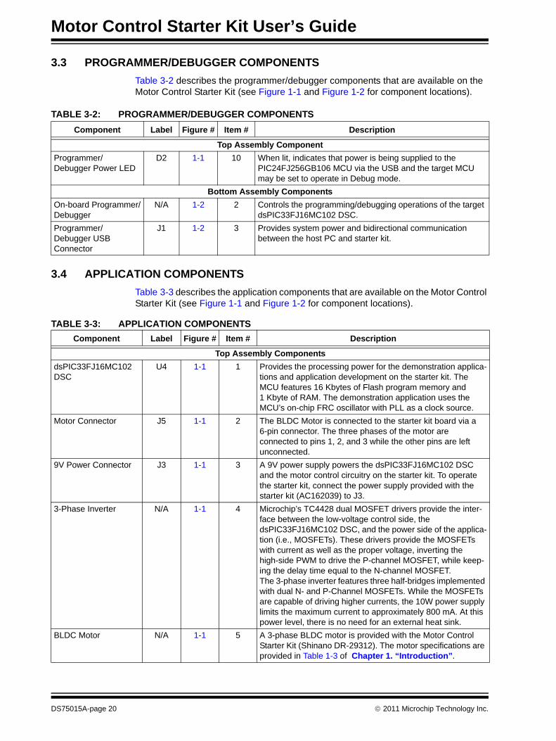
3.3 PROGRAMMER/DEBUGGER COMPONENTSTable 3-2 describes the programmer/debugger components that are available on the Motor Control Starter Kit (see Figure 1-1 and Figure 1-2 for component locations).
TABLE 3-2: PROGRAMMER/DEBUGGER COMPONENTS
3.4 APPLICATION COMPONENTSTable 3-3 describes the application components that are available on the Motor Control Starter Kit (see Figure 1-1 and Figure 1-2 for component locations).
Component Label Figure # Item # Description
Top Assembly ComponentProgrammer/Debugger Power LED
D2 1-1 10 When lit, indicates that power is being supplied to the PIC24FJ256GB106 MCU via the USB and the target MCU may be set to operate in Debug mode.
Bottom Assembly ComponentsOn-board Programmer/Debugger
N/A 1-2 2 Controls the programming/debugging operations of the target dsPIC33FJ16MC102 DSC.
Programmer/Debugger USB Connector
J1 1-2 3 Provides system power and bidirectional communication between the host PC and starter kit.
TABLE 3-3: APPLICATION COMPONENTSComponent Label Figure # Item # Description
Top Assembly ComponentsdsPIC33FJ16MC102 DSC
U4 1-1 1 Provides the processing power for the demonstration applica-tions and application development on the starter kit. The MCU features 16 Kbytes of Flash program memory and 1 Kbyte of RAM. The demonstration application uses the MCU’s on-chip FRC oscillator with PLL as a clock source.
Motor Connector J5 1-1 2 The BLDC Motor is connected to the starter kit board via a 6-pin connector. The three phases of the motor are connected to pins 1, 2, and 3 while the other pins are left unconnected.
9V Power Connector J3 1-1 3 A 9V power supply powers the dsPIC33FJ16MC102 DSC and the motor control circuitry on the starter kit. To operate the starter kit, connect the power supply provided with the starter kit (AC162039) to J3.
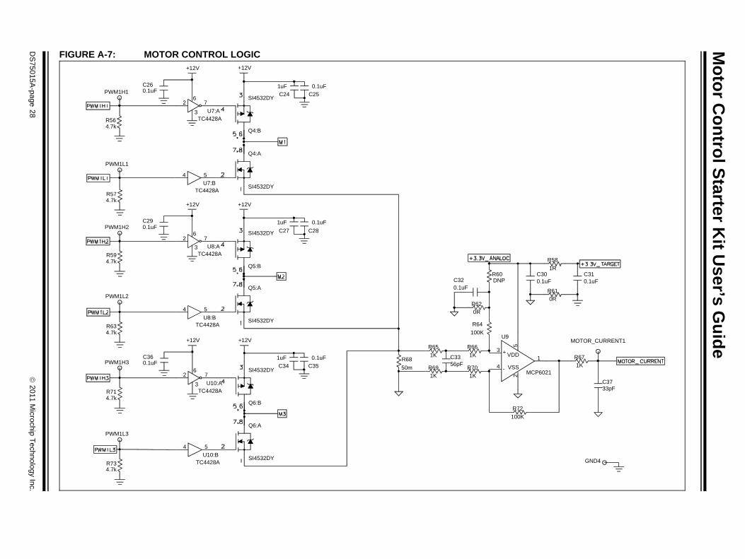
3-Phase Inverter N/A 1-1 4 Microchip’s TC4428 dual MOSFET drivers provide the inter-face between the low-voltage control side, the dsPIC33FJ16MC102 DSC, and the power side of the applica-tion (i.e., MOSFETs). These drivers provide the MOSFETs with current as well as the proper voltage, inverting the high-side PWM to drive the P-channel MOSFET, while keep-ing the delay time equal to the N-channel MOSFET.The 3-phase inverter features three half-bridges implemented with dual N- and P-Channel MOSFETs. While the MOSFETs are capable of driving higher currents, the 10W power supply limits the maximum current to approximately 800 mA. At this power level, there is no need for an external heat sink.
BLDC Motor N/A 1-1 5 A 3-phase BLDC motor is provided with the Motor Control Starter Kit (Shinano DR-29312). The motor specifications are provided in Table 1-3 of Chapter 1. “Introduction”.
DS75015A-page 20 © 2011 Microchip Technology Inc.
Hardware
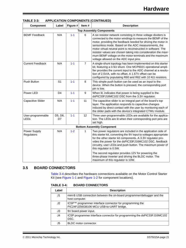
3.5 BOARD CONNECTORSTable 3-4 describes the hardware connections available on the Motor Control Starter Kit (see Figure 1-1 and Figure 1-2 for component locations).
TABLE 3-4: BOARD CONNECTORS
Top Assembly ComponentsBEMF Feedback N/A 1-1 6 A six resistor network consisting in three voltage dividers is
connected to the motor windings to measure the BEMF of the motor, providing the feedback needed for driving the motor in sensorless mode. Based on the ADC measurements, the motor virtual neutral point is reconstructed in software. The resistor values are chosen taking into consideration the maxi-mum BEMF voltage on the motor terminals and the maximum voltage allowed on the ADC input pins.
Current Feedback N/A 1-1 7 A single-shunt topology has been implemented on this starter kit, featuring a 0.5Ω shunt. One MCP6021 operational ampli-fier provides the current input to the ADC channel at a resolu-tion of 2.5V/A, with no offset. A 1.67V offset can be configured by populating R60 and R62 with 10 KΩ resistors.
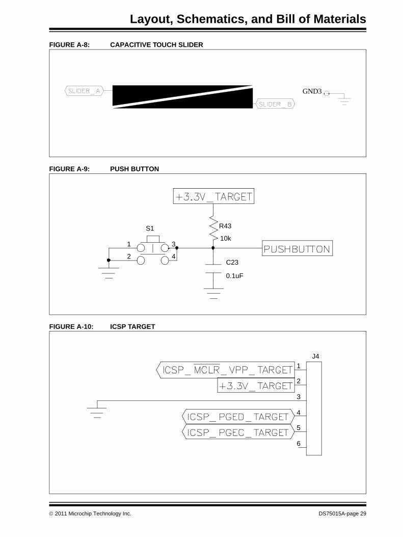
Push Button S1 1-1 8 This simple push button can be used as an input to the device. When the button is pressed, the corresponding port pin is low.
Power LED D4 1-1 9 When lit, indicates that power is being supplied to the dsPIC33FJ16MC102 DSC from the 3.3V regulator.
Capacitive Slider N/A 1-1 11 The capacitive slider is an integral part of the board’s top layer. The application responds to capacitive changes induced by direct contact with the user by monitoring each of the slider pads with the device’s integrated CTMU module.
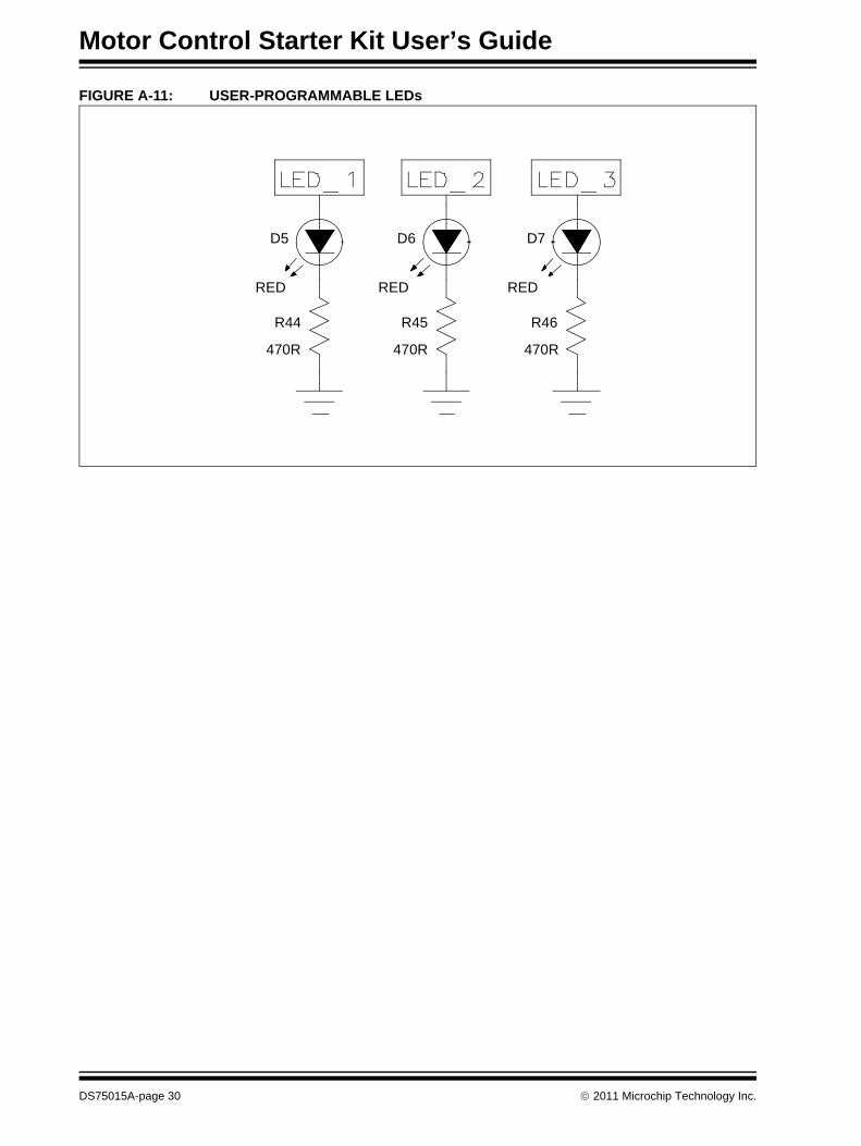
User-programmable LEDs
D5, D6, D7
1-1 12 Three user-programmable LEDs are available for the applica-tion. The LEDs are lit when their corresponding port pins are set high.
Bottom Assembly ComponentPower Supply Regulators
N/A 1-2 1 Two power regulators are included in the application side of this starter kit, converting the 9V input to voltages appropriate for the other starter kit components. A 3.3V regulator pro-vides the power for the dsPIC33FJ16MC102 DSC, feedback circuitry, user LEDs and push button. The maximum power of this regulator is 0.5W.
The second regulator provides 12V for powering the three-phase inverter and driving the BLDC motor. The maximum of this regulator is 10W.
TABLE 3-3: APPLICATION COMPONENTS (CONTINUED)Component Label Figure # Item # Description
Label Description
J1 mini-B USB connection between the on-board programmer/debugger and the host computer.
J2 ICSP™ programmer interface connector for programming the PIC24FJ256GB106 MCU USB-to-UART bridge.
J3 9V board power input.J4 ICSP programmer interface connector for programming the dsPIC33FJ16MC102
DSC.J5 BLDC motor connector.
© 2011 Microchip Technology Inc. DS75015A-page 21
Motor Control Starter Kit User’s Guide
3.6 INDICATORS AND HUMAN INTERFACESTable 3-5 describes the user interaction interfaces available on the starter kit (see Figure 1-1 and Figure 1-2 for component locations).
TABLE 3-5: INDICATORS AND HUMAN INTERFACES
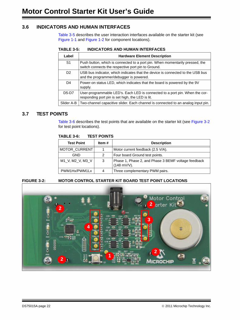
3.7 TEST POINTSTable 3-6 describes the test points that are available on the starter kit (see Figure 3-2 for test point locations).
TABLE 3-6: TEST POINTS
FIGURE 3-2: MOTOR CONTROL STARTER KIT BOARD TEST POINT LOCATIONS
Label Hardware Element Description
S1 Push button, which is connected to a port pin. When momentarily pressed, the switch connects the respective port pin to Ground.
D2 USB bus indicator, which indicates that the device is connected to the USB bus and the programmer/debugger is powered.
D4 Power-on status LED, which indicates that the board is powered by the 9V supply.
D5-D7 User-programmable LED’s. Each LED is connected to a port pin. When the cor-responding port pin is set high, the LED is lit.
Slider A-B Two-channel capacitive slider. Each channel is connected to an analog input pin.
Test Point Item # Description
MOTOR_CURRENT 1 Motor current feedback (2.5 V/A).GND 2 Four board Ground test points.
M1_V, M2_V, M3_V 3 Phase 1, Phase 2, and Phase 3 BEMF voltage feedback (148 mV/V).
PWM1Hx/PWM1Lx 4 Three complementary PWM pairs.
1
4
22
2
3
2
DS75015A-page 22 © 2011 Microchip Technology Inc.
MOTOR CONTROL STARTER
KIT USER’S GUIDEAppendix A. Layout, Schematics, and Bill of Materials
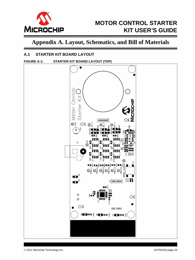
A.1 STARTER KIT BOARD LAYOUTFIGURE A-1: STARTER KIT BOARD LAYOUT (TOP)
© 2011 Microchip Technology Inc. DS75015A-page 23
Motor Control Starter Kit User’s Guide
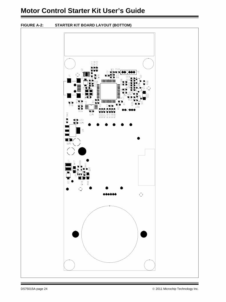
FIGURE A-2: STARTER KIT BOARD LAYOUT (BOTTOM)
DS75015A-page 24 © 2011 Microchip Technology Inc.
Layout, Schematics, and B
ill of Materials
© 2011 M
icrochip Technology Inc.D
S75015A
-page 25
A
F
C10
0.1uFR102.2K
+3.3V
R12330R
10K
C12
0.01uF
C11
2.2uF
GreenD2
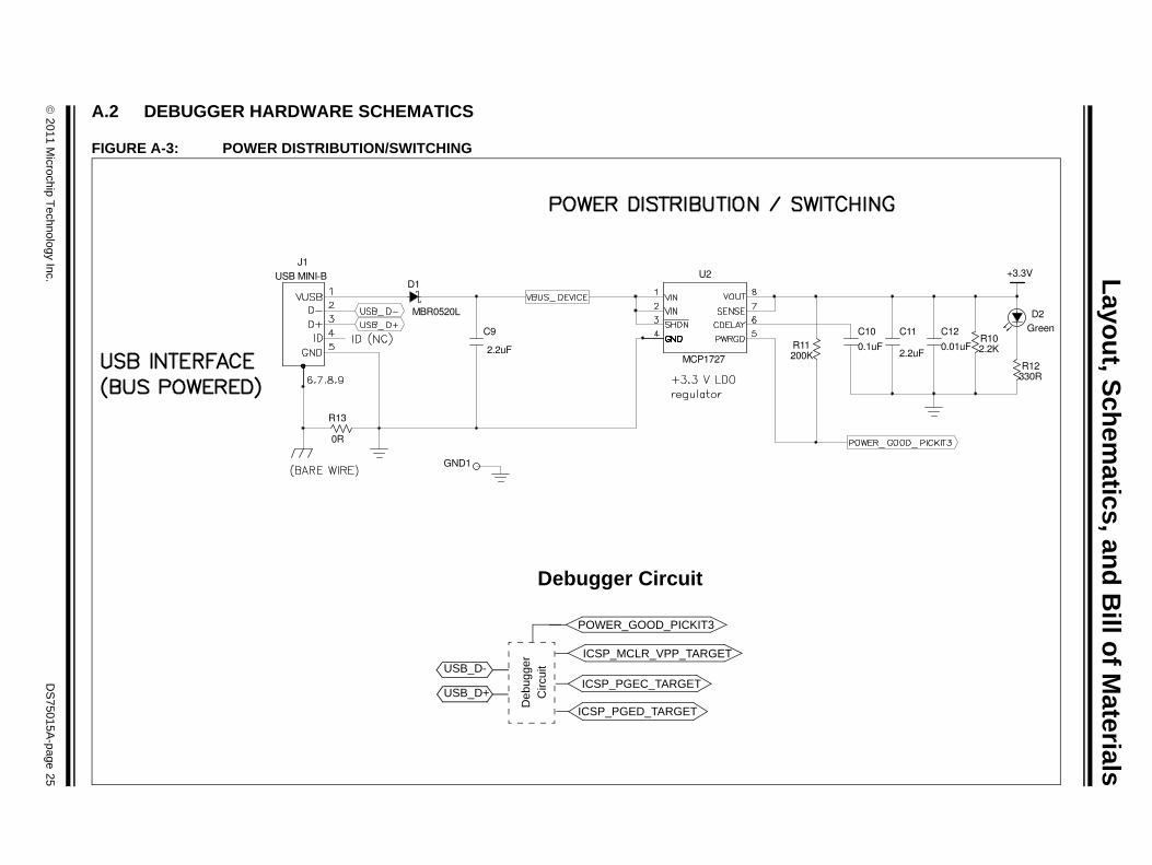
.2 DEBUGGER HARDWARE SCHEMATICS
IGURE A-3: POWER DISTRIBUTION/SWITCHING
0R
R13
D1
MBR0520L
C9
2.2uF R120
J1USB MINI-B
GND1
MCP1727
U2
USB_D-
USB_D+
Deb
ugge
rC
ircui
t
POWER_GOOD_PICKIT3
ICSP_MCLR_VPP_TARGET
ICSP_PGEC_TARGET
ICSP_PGED_TARGET
Debugger Circuit
Motor Control Starter Kit User’s Guide
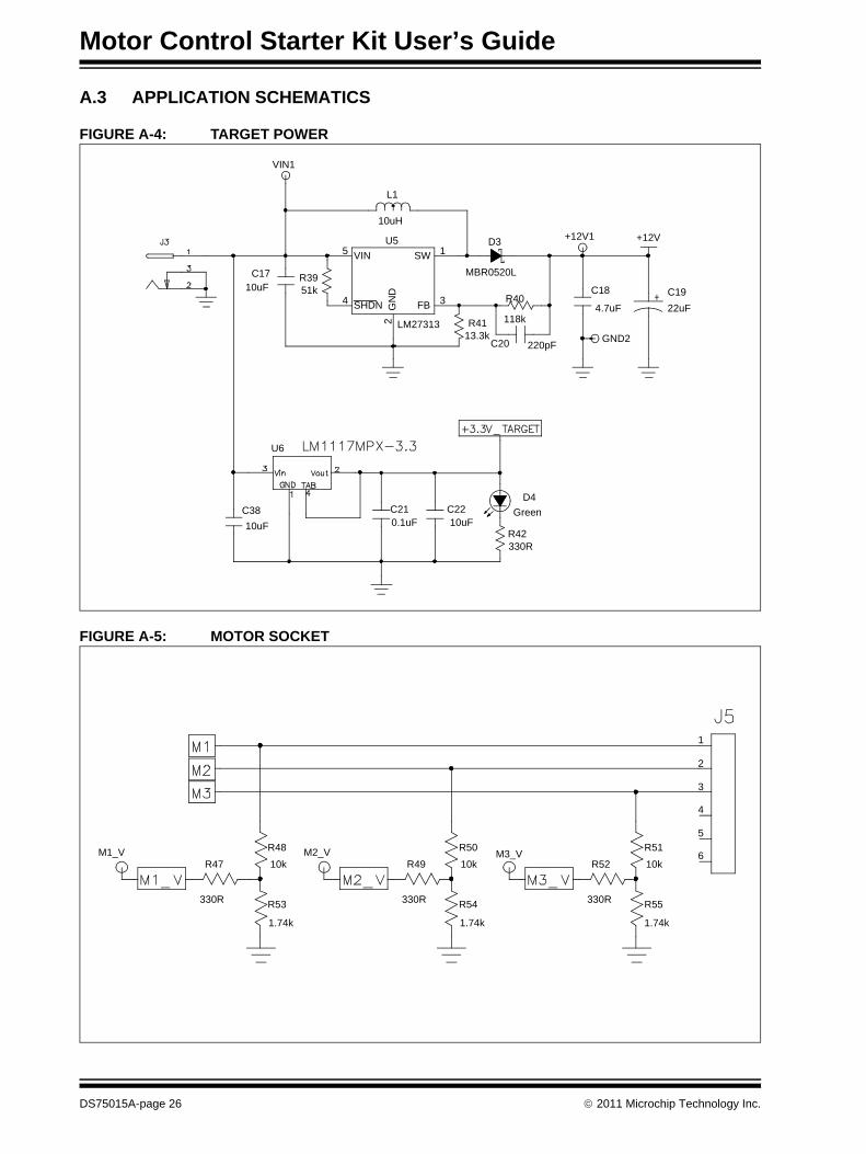
A.3 APPLICATION SCHEMATICS
FIGURE A-4: TARGET POWER
FIGURE A-5: MOTOR SOCKET
GND2
R3951k
VIN1
C210.1uF
L1
10uH
D4Green
R40
118k
C18
4.7uF
R42330R
R4113.3k
MBR0520L
D3 +12V1
10uFC17
C2210uF
22uFC19
C3810uF
+12V
C20 220pF
4 SHDN
5 VIN
2G
ND
3FB
1SWU5
LM27313
U6
M1_VR47
330R R53
1.74k
R49
330R
M3_V
R55
1.74k
R4810k
R5110kR52
330R
M2_V
R54
1.74k
R5010k
5
2
1
3
4
6
DS75015A-page 26 © 2011 Microchip Technology Inc.
Layout, Schematics, and B
ill of Materials
© 2011 M
icrochip Technology Inc.D
S75015A
-page 27
F
R3610k
IGURE A-6: dsPIC33FJ16MC102 DIGITAL SIGNAL CONTROLLER
R3810k
C15
0.1uF
C14
10uF
R3710k
C16
0.1uF
*Internal connection for comparator using PPS
10
5
29G
ND
_Pad
15
18
21
23
26
1617
1920
2425
22
2728
14
11
8
6
3
9
1213
4
7
12
dsPIC33FJ16MC102
U4
Motor C
ontrol Starter Kit U
ser’s Guide
DS
75015A-page 28
© 2011 M
icrochip Technology Inc.
100KR72
C3733pF
0RR61
1RR58
GND4
MOTOR_CURRENT1
1KR67
+
-
1
2
VSS
5
VDD
U9
MCP6021
0.1uFC30
P 0.1uFC31
FIGURE A-7: MOTOR CONTROL LOGIC
PWM1L3
R714.7k
PWM1H3
PWM1L2
R594.7k
R574.7k
PWM1L1
PWM1H1
C350.1uF R68
50m
1KR66
0RR62
R634.7k
R734.7k
PWM1H2
R564.7k
C280.1uF
C250.1uF
100KR64
1KR70
0.1uFC32
0.1uFC36
4 5U10:B
TC4428A
C341uF
+12V +12V
6
32 7
TC4428AU8:A
+12V +12V
6
3
2 7
TC4428AU7:A
+12V+12V
C3356pF
1KR65
0.1uFC29
0.1uFC26
SI4532DY
Q6:B
SI4532DY
Q6:A
4 5U8:B
TC4428A
6
3
2 7
TC4428AU10:A
C271uF
SI4532DY
Q4:A
SI4532DY
Q5:B
4 5U7:B
TC4428A
C241uF
1KR69
3
4
R60DN
SI4532DY
Q4:B
SI4532DY
Q5:A
Layout, Schematics, and Bill of Materials
FIGURE A-8: CAPACITIVE TOUCH SLIDER
FIGURE A-9: PUSH BUTTON
FIGURE A-10: ICSP TARGET
GND3
4
3
2
1
S1 R43
10k
0.1uF
C23
5
2
1
3
4
6
J4
© 2011 Microchip Technology Inc. DS75015A-page 29
Motor Control Starter Kit User’s Guide
FIGURE A-11: USER-PROGRAMMABLE LEDs
R45
470R
D6
RED
R46
470R
R44
470R
D7
RED
D5
RED
DS75015A-page 30 © 2011 Microchip Technology Inc.
Layout, Schematics, and Bill of Materials
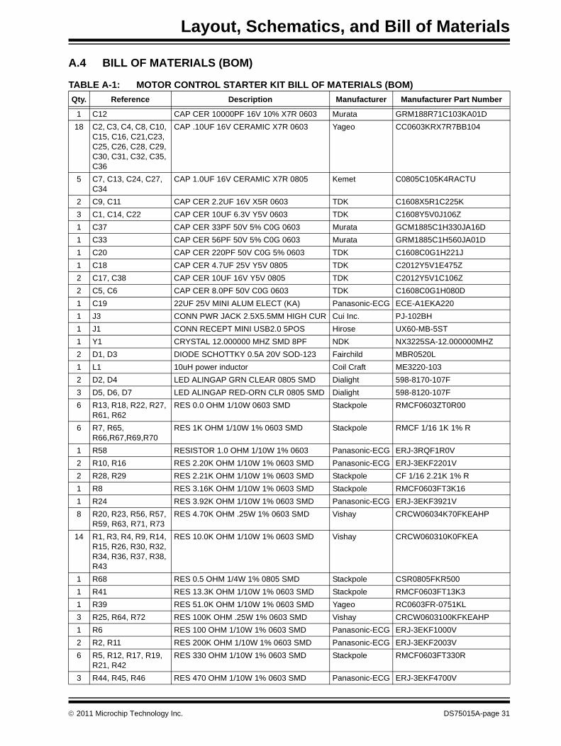
A.4 BILL OF MATERIALS (BOM)
TABLE A-1: MOTOR CONTROL STARTER KIT BILL OF MATERIALS (BOM)Qty. Reference Description Manufacturer Manufacturer Part Number
1 C12 CAP CER 10000PF 16V 10% X7R 0603 Murata GRM188R71C103KA01D18 C2, C3, C4, C8, C10,
C15, C16, C21,C23, C25, C26, C28, C29, C30, C31, C32, C35, C36
CAP .10UF 16V CERAMIC X7R 0603 Yageo CC0603KRX7R7BB104
5 C7, C13, C24, C27, C34
CAP 1.0UF 16V CERAMIC X7R 0805 Kemet C0805C105K4RACTU
2 C9, C11 CAP CER 2.2UF 16V X5R 0603 TDK C1608X5R1C225K3 C1, C14, C22 CAP CER 10UF 6.3V Y5V 0603 TDK C1608Y5V0J106Z1 C37 CAP CER 33PF 50V 5% C0G 0603 Murata GCM1885C1H330JA16D1 C33 CAP CER 56PF 50V 5% C0G 0603 Murata GRM1885C1H560JA01D1 C20 CAP CER 220PF 50V C0G 5% 0603 TDK C1608C0G1H221J1 C18 CAP CER 4.7UF 25V Y5V 0805 TDK C2012Y5V1E475Z2 C17, C38 CAP CER 10UF 16V Y5V 0805 TDK C2012Y5V1C106Z2 C5, C6 CAP CER 8.0PF 50V C0G 0603 TDK C1608C0G1H080D1 C19 22UF 25V MINI ALUM ELECT (KA) Panasonic-ECG ECE-A1EKA2201 J3 CONN PWR JACK 2.5X5.5MM HIGH CUR Cui Inc. PJ-102BH1 J1 CONN RECEPT MINI USB2.0 5POS Hirose UX60-MB-5ST1 Y1 CRYSTAL 12.000000 MHZ SMD 8PF NDK NX3225SA-12.000000MHZ2 D1, D3 DIODE SCHOTTKY 0.5A 20V SOD-123 Fairchild MBR0520L1 L1 10uH power inductor Coil Craft ME3220-1032 D2, D4 LED ALINGAP GRN CLEAR 0805 SMD Dialight 598-8170-107F3 D5, D6, D7 LED ALINGAP RED-ORN CLR 0805 SMD Dialight 598-8120-107F6 R13, R18, R22, R27,
R61, R62RES 0.0 OHM 1/10W 0603 SMD Stackpole RMCF0603ZT0R00
6 R7, R65, R66,R67,R69,R70
RES 1K OHM 1/10W 1% 0603 SMD Stackpole RMCF 1/16 1K 1% R
1 R58 RESISTOR 1.0 OHM 1/10W 1% 0603 Panasonic-ECG ERJ-3RQF1R0V2 R10, R16 RES 2.20K OHM 1/10W 1% 0603 SMD Panasonic-ECG ERJ-3EKF2201V2 R28, R29 RES 2.21K OHM 1/10W 1% 0603 SMD Stackpole CF 1/16 2.21K 1% R1 R8 RES 3.16K OHM 1/10W 1% 0603 SMD Stackpole RMCF0603FT3K161 R24 RES 3.92K OHM 1/10W 1% 0603 SMD Panasonic-ECG ERJ-3EKF3921V8 R20, R23, R56, R57,
R59, R63, R71, R73RES 4.70K OHM .25W 1% 0603 SMD Vishay CRCW06034K70FKEAHP
14 R1, R3, R4, R9, R14, R15, R26, R30, R32, R34, R36, R37, R38, R43
RES 10.0K OHM 1/10W 1% 0603 SMD Vishay CRCW060310K0FKEA
1 R68 RES 0.5 OHM 1/4W 1% 0805 SMD Stackpole CSR0805FKR5001 R41 RES 13.3K OHM 1/10W 1% 0603 SMD Stackpole RMCF0603FT13K31 R39 RES 51.0K OHM 1/10W 1% 0603 SMD Yageo RC0603FR-0751KL3 R25, R64, R72 RES 100K OHM .25W 1% 0603 SMD Vishay CRCW0603100KFKEAHP1 R6 RES 100 OHM 1/10W 1% 0603 SMD Panasonic-ECG ERJ-3EKF1000V2 R2, R11 RES 200K OHM 1/10W 1% 0603 SMD Panasonic-ECG ERJ-3EKF2003V6 R5, R12, R17, R19,
R21, R42RES 330 OHM 1/10W 1% 0603 SMD Stackpole RMCF0603FT330R
3 R44, R45, R46 RES 470 OHM 1/10W 1% 0603 SMD Panasonic-ECG ERJ-3EKF4700V
© 2011 Microchip Technology Inc. DS75015A-page 31
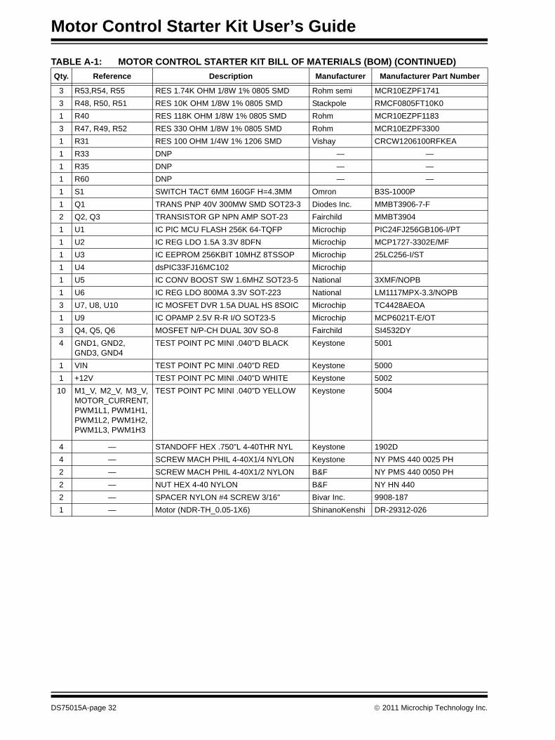
Motor Control Starter Kit User’s Guide
3 R53,R54, R55 RES 1.74K OHM 1/8W 1% 0805 SMD Rohm semi MCR10EZPF17413 R48, R50, R51 RES 10K OHM 1/8W 1% 0805 SMD Stackpole RMCF0805FT10K01 R40 RES 118K OHM 1/8W 1% 0805 SMD Rohm MCR10EZPF11833 R47, R49, R52 RES 330 OHM 1/8W 1% 0805 SMD Rohm MCR10EZPF33001 R31 RES 100 OHM 1/4W 1% 1206 SMD Vishay CRCW1206100RFKEA1 R33 DNP — —1 R35 DNP — —1 R60 DNP — —1 S1 SWITCH TACT 6MM 160GF H=4.3MM Omron B3S-1000P1 Q1 TRANS PNP 40V 300MW SMD SOT23-3 Diodes Inc. MMBT3906-7-F2 Q2, Q3 TRANSISTOR GP NPN AMP SOT-23 Fairchild MMBT39041 U1 IC PIC MCU FLASH 256K 64-TQFP Microchip PIC24FJ256GB106-I/PT1 U2 IC REG LDO 1.5A 3.3V 8DFN Microchip MCP1727-3302E/MF1 U3 IC EEPROM 256KBIT 10MHZ 8TSSOP Microchip 25LC256-I/ST1 U4 dsPIC33FJ16MC102 Microchip1 U5 IC CONV BOOST SW 1.6MHZ SOT23-5 National 3XMF/NOPB1 U6 IC REG LDO 800MA 3.3V SOT-223 National LM1117MPX-3.3/NOPB3 U7, U8, U10 IC MOSFET DVR 1.5A DUAL HS 8SOIC Microchip TC4428AEOA1 U9 IC OPAMP 2.5V R-R I/O SOT23-5 Microchip MCP6021T-E/OT3 Q4, Q5, Q6 MOSFET N/P-CH DUAL 30V SO-8 Fairchild SI4532DY4 GND1, GND2,
GND3, GND4TEST POINT PC MINI .040"D BLACK Keystone 5001
1 VIN TEST POINT PC MINI .040"D RED Keystone 50001 +12V TEST POINT PC MINI .040"D WHITE Keystone 500210 M1_V, M2_V, M3_V,
MOTOR_CURRENT,PWM1L1, PWM1H1, PWM1L2, PWM1H2, PWM1L3, PWM1H3
TEST POINT PC MINI .040"D YELLOW Keystone 5004
4 — STANDOFF HEX .750"L 4-40THR NYL Keystone 1902D4 — SCREW MACH PHIL 4-40X1/4 NYLON Keystone NY PMS 440 0025 PH2 — SCREW MACH PHIL 4-40X1/2 NYLON B&F NY PMS 440 0050 PH2 — NUT HEX 4-40 NYLON B&F NY HN 4402 — SPACER NYLON #4 SCREW 3/16" Bivar Inc. 9908-1871 — Motor (NDR-TH_0.05-1X6) ShinanoKenshi DR-29312-026
TABLE A-1: MOTOR CONTROL STARTER KIT BILL OF MATERIALS (BOM) (CONTINUED)Qty. Reference Description Manufacturer Manufacturer Part Number
DS75015A-page 32 © 2011 Microchip Technology Inc.

© 2011 Microchip Technology Inc. DS75015A-page 33
NOTES:
DS75015A-page 34 © 2011 Microchip Technology Inc.
AMERICASCorporate Office2355 West Chandler Blvd.Chandler, AZ 85224-6199Tel: 480-792-7200 Fax: 480-792-7277Technical Support: http://www.microchip.com/supportWeb Address: www.microchip.comAtlantaDuluth, GA Tel: 678-957-9614 Fax: 678-957-1455BostonWestborough, MA Tel: 774-760-0087 Fax: 774-760-0088ChicagoItasca, IL Tel: 630-285-0071 Fax: 630-285-0075ClevelandIndependence, OH Tel: 216-447-0464 Fax: 216-447-0643DallasAddison, TX Tel: 972-818-7423 Fax: 972-818-2924DetroitFarmington Hills, MI Tel: 248-538-2250Fax: 248-538-2260IndianapolisNoblesville, IN Tel: 317-773-8323Fax: 317-773-5453Los AngelesMission Viejo, CA Tel: 949-462-9523 Fax: 949-462-9608Santa ClaraSanta Clara, CA Tel: 408-961-6444Fax: 408-961-6445TorontoMississauga, Ontario, CanadaTel: 905-673-0699 Fax: 905-673-6509
ASIA/PACIFICAsia Pacific OfficeSuites 3707-14, 37th FloorTower 6, The GatewayHarbour City, KowloonHong KongTel: 852-2401-1200Fax: 852-2401-3431Australia - SydneyTel: 61-2-9868-6733Fax: 61-2-9868-6755China - BeijingTel: 86-10-8569-7000 Fax: 86-10-8528-2104China - ChengduTel: 86-28-8665-5511Fax: 86-28-8665-7889China - ChongqingTel: 86-23-8980-9588Fax: 86-23-8980-9500China - HangzhouTel: 86-571-2819-3180 Fax: 86-571-2819-3189China - Hong Kong SARTel: 852-2401-1200 Fax: 852-2401-3431China - NanjingTel: 86-25-8473-2460Fax: 86-25-8473-2470China - QingdaoTel: 86-532-8502-7355Fax: 86-532-8502-7205China - ShanghaiTel: 86-21-5407-5533 Fax: 86-21-5407-5066China - ShenyangTel: 86-24-2334-2829Fax: 86-24-2334-2393China - ShenzhenTel: 86-755-8203-2660 Fax: 86-755-8203-1760China - WuhanTel: 86-27-5980-5300Fax: 86-27-5980-5118China - XianTel: 86-29-8833-7252Fax: 86-29-8833-7256China - XiamenTel: 86-592-2388138 Fax: 86-592-2388130China - ZhuhaiTel: 86-756-3210040 Fax: 86-756-3210049
ASIA/PACIFICIndia - BangaloreTel: 91-80-3090-4444 Fax: 91-80-3090-4123India - New DelhiTel: 91-11-4160-8631Fax: 91-11-4160-8632India - PuneTel: 91-20-2566-1512Fax: 91-20-2566-1513Japan - YokohamaTel: 81-45-471- 6166 Fax: 81-45-471-6122Korea - DaeguTel: 82-53-744-4301Fax: 82-53-744-4302Korea - SeoulTel: 82-2-554-7200Fax: 82-2-558-5932 or 82-2-558-5934Malaysia - Kuala LumpurTel: 60-3-6201-9857Fax: 60-3-6201-9859Malaysia - PenangTel: 60-4-227-8870Fax: 60-4-227-4068Philippines - ManilaTel: 63-2-634-9065Fax: 63-2-634-9069SingaporeTel: 65-6334-8870Fax: 65-6334-8850Taiwan - Hsin ChuTel: 886-3-6578-300Fax: 886-3-6578-370Taiwan - KaohsiungTel: 886-7-213-7830Fax: 886-7-330-9305Taiwan - TaipeiTel: 886-2-2500-6610 Fax: 886-2-2508-0102Thailand - BangkokTel: 66-2-694-1351Fax: 66-2-694-1350
EUROPEAustria - WelsTel: 43-7242-2244-39Fax: 43-7242-2244-393Denmark - CopenhagenTel: 45-4450-2828 Fax: 45-4485-2829France - ParisTel: 33-1-69-53-63-20 Fax: 33-1-69-30-90-79Germany - MunichTel: 49-89-627-144-0 Fax: 49-89-627-144-44Italy - Milan Tel: 39-0331-742611 Fax: 39-0331-466781Netherlands - DrunenTel: 31-416-690399 Fax: 31-416-690340Spain - MadridTel: 34-91-708-08-90Fax: 34-91-708-08-91UK - WokinghamTel: 44-118-921-5869Fax: 44-118-921-5820
Worldwide Sales and Service
05/02/11