motorola ap 5131 manual
DESCRIPTION
Manual For Motorola AP 5131TRANSCRIPT

7/18/2019 Motorola AP 5131 Manual
http://slidepdf.com/reader/full/motorola-ap-5131-manual 1/613
Motorola SolutionsAP 5131
PRODUCT REFERENCE GUIDE

7/18/2019 Motorola AP 5131 Manual
http://slidepdf.com/reader/full/motorola-ap-5131-manual 2/613
7/18/2019 Motorola AP 5131 Manual
http://slidepdf.com/reader/full/motorola-ap-5131-manual 3/613
MOTOROLA SOLUTIONS AP 51XXPRODUCT REFERENCE GUIDE
72E-157066-01
Revision A
January 2012

7/18/2019 Motorola AP 5131 Manual
http://slidepdf.com/reader/full/motorola-ap-5131-manual 4/613
ii WiNG 4.4 AP-5131 Product Reference Guide
No part of this publication may be reproduced or used in any form, or by any electrical or mechanical means,
without permission in writing from Motorola Solutions. This includes electronic or mechanical means, such as
photocopying, recording, or information storage and retrieval systems. The material in this manual is subject to
change without notice.
The software is provided strictly on an “as is” basis. All software, including firmware, furnished to the user is ona licensed basis. Motorola Solutions grants to the user a non-transferable and non-exclusive license to use
each software or firmware program delivered hereunder (licensed program). Except as noted below, such
license may not be assigned, sublicensed, or otherwise transferred by the user without prior written consent of
Motorola Solutions. No right to copy a licensed program in whole or in part is granted, except as permitted
under copyright law. The user shall not modify, merge, or incorporate any form or portion of a licensed program
with other program material, create a derivative work from a licensed program, or use a licensed program in a
network without written permission from Motorola Solutions. The user agrees to maintain Motorola Solutions’s
copyright notice on the licensed programs delivered hereunder, and to include the same on any authorized
copies it makes, in whole or in part. The user agrees not to decompile, disassemble, decode, or reverse
engineer any licensed program delivered to the user or any portion thereof.
Motorola Solutions reserves the right to make changes to any software or product to improve reliability,
function, or design.
Motorola Solutions does not assume any product liability arising out of, or in connection with, the application or
use of any product, circuit, or application described herein.
No license is granted, either expressly or by implication, estoppel, or otherwise under any Motorola Solutions,
Inc., intellectual property rights. An implied license only exists for equipment, circuits, and subsystems
contained in Motorola Solutions products.

7/18/2019 Motorola AP 5131 Manual
http://slidepdf.com/reader/full/motorola-ap-5131-manual 5/613
ii
Revision History
Changes to the original guide are listed below:
Change Date Description
Rev A January 2012 Manual updated to WiNG 4.4 baseline

7/18/2019 Motorola AP 5131 Manual
http://slidepdf.com/reader/full/motorola-ap-5131-manual 6/613
iv WiNG 4.4 AP-5131 Product Reference Guide

7/18/2019 Motorola AP 5131 Manual
http://slidepdf.com/reader/full/motorola-ap-5131-manual 7/613
CONTENTS
ABOUT THIS GUIDE
CHAPTER 1 INTRODUCTION1.1 New Features . . . . . . . . . . . . . . . . . . . . . . . . . . . . . . . . . . . . . . . . . . . . . . . . . . . . . . . . . . . . . . . . . . . . . . . . . . . . . . . . . . . . . . . . . . . . . . . . . . . 1-2
1.1.1 WIPS Support . . . . . . . . . . . . . . . . . . . . . . . . . . . . . . . . . . . . . . . . . . . . . . . . . . . . . . . . . . . . . . . . . . . . . . . . . . . . . . . . . . . . . . . . . . . . . 1-2
1.1.2 Trusted Host Management . . . . . . . . . . . . . . . . . . . . . . . . . . . . . . . . . . . . . . . . . . . . . . . . . . . . . . . . . . . . . . . . . . . . . . . . . . . . . . . . . . . 1-2
1.1.3 Apache Certificate Management . . . . . . . . . . . . . . . . . . . . . . . . . . . . . . . . . . . . . . . . . . . . . . . . . . . . . . . . . . . . . . . . . . . . . . . . . . . . . . 1-2
1.1.4 Adaptive AP . . . . . . . . . . . . . . . . . . . . . . . . . . . . . . . . . . . . . . . . . . . . . . . . . . . . . . . . . . . . . . . . . . . . . . . . . . . . . . . . . . . . . . . . . . . . . . 1-3
1.1.5 Rogue AP Enhancements . . . . . . . . . . . . . . . . . . . . . . . . . . . . . . . . . . . . . . . . . . . . . . . . . . . . . . . . . . . . . . . . . . . . . . . . . . . . . . . . . . . . 1-3
1.1.6 Bandwidth Management Enhancements . . . . . . . . . . . . . . . . . . . . . . . . . . . . . . . . . . . . . . . . . . . . . . . . . . . . . . . . . . . . . . . . . . . . . . . . 1-3
1.1.7 Radius Time-Based Authentication . . . . . . . . . . . . . . . . . . . . . . . . . . . . . . . . . . . . . . . . . . . . . . . . . . . . . . . . . . . . . . . . . . . . . . . . . . . . 1-3
1.1.8 QBSS Support . . . . . . . . . . . . . . . . . . . . . . . . . . . . . . . . . . . . . . . . . . . . . . . . . . . . . . . . . . . . . . . . . . . . . . . . . . . . . . . . . . . . . . . . . . . . . 1-3
1.2 Feature Overview . . . . . . . . . . . . . . . . . . . . . . . . . . . . . . . . . . . . . . . . . . . . . . . . . . . . . . . . . . . . . . . . . . . . . . . . . . . . . . . . . . . . . . . . . . . . . . . . 1-41.2.1 Single or Dual Mode Radio Options . . . . . . . . . . . . . . . . . . . . . . . . . . . . . . . . . . . . . . . . . . . . . . . . . . . . . . . . . . . . . . . . . . . . . . . . . . . . 1-5
1.2.2 Separate LAN and WAN Ports . . . . . . . . . . . . . . . . . . . . . . . . . . . . . . . . . . . . . . . . . . . . . . . . . . . . . . . . . . . . . . . . . . . . . . . . . . . . . . . . 1-5
1.2.3 Multiple Mounting Options . . . . . . . . . . . . . . . . . . . . . . . . . . . . . . . . . . . . . . . . . . . . . . . . . . . . . . . . . . . . . . . . . . . . . . . . . . . . . . . . . . 1-5
1.2.4 Antenna Support for 2.4 GHz and 5 GHz Radios . . . . . . . . . . . . . . . . . . . . . . . . . . . . . . . . . . . . . . . . . . . . . . . . . . . . . . . . . . . . . . . . . . 1-5
1.2.5 Sixteen Configurable WLANs . . . . . . . . . . . . . . . . . . . . . . . . . . . . . . . . . . . . . . . . . . . . . . . . . . . . . . . . . . . . . . . . . . . . . . . . . . . . . . . . . 1-5
1.2.6 Support for 4 BSSIDs per Radio . . . . . . . . . . . . . . . . . . . . . . . . . . . . . . . . . . . . . . . . . . . . . . . . . . . . . . . . . . . . . . . . . . . . . . . . . . . . . . . 1-6
1.2.7 Quality of Service (QoS) Support . . . . . . . . . . . . . . . . . . . . . . . . . . . . . . . . . . . . . . . . . . . . . . . . . . . . . . . . . . . . . . . . . . . . . . . . . . . . . . 1-6
1.2.8 Industry Leading Data Security . . . . . . . . . . . . . . . . . . . . . . . . . . . . . . . . . . . . . . . . . . . . . . . . . . . . . . . . . . . . . . . . . . . . . . . . . . . . . . . 1-6
1.2.9 VLAN Support . . . . . . . . . . . . . . . . . . . . . . . . . . . . . . . . . . . . . . . . . . . . . . . . . . . . . . . . . . . . . . . . . . . . . . . . . . . . . . . . . . . . . . . . . . . . . 1-9
1.2.10 Multiple Management Accessibility Options . . . . . . . . . . . . . . . . . . . . . . . . . . . . . . . . . . . . . . . . . . . . . . . . . . . . . . . . . . . . . . . . . . . . 1-9
1.2.11 Updatable Firmware . . . . . . . . . . . . . . . . . . . . . . . . . . . . . . . . . . . . . . . . . . . . . . . . . . . . . . . . . . . . . . . . . . . . . . . . . . . . . . . . . . . . . . 1-10
1.2.12 Programmable SNMP v1/v2/v3 Trap Support . . . . . . . . . . . . . . . . . . . . . . . . . . . . . . . . . . . . . . . . . . . . . . . . . . . . . . . . . . . . . . . . . . 1-10
1.2.13 Power-over-Ethernet Support . . . . . . . . . . . . . . . . . . . . . . . . . . . . . . . . . . . . . . . . . . . . . . . . . . . . . . . . . . . . . . . . . . . . . . . . . . . . . . . 1-101.2.14 MU-MU Transmission Disallow . . . . . . . . . . . . . . . . . . . . . . . . . . . . . . . . . . . . . . . . . . . . . . . . . . . . . . . . . . . . . . . . . . . . . . . . . . . . . 1-10
1.2.15 Voice Prioritization . . . . . . . . . . . . . . . . . . . . . . . . . . . . . . . . . . . . . . . . . . . . . . . . . . . . . . . . . . . . . . . . . . . . . . . . . . . . . . . . . . . . . . . 1-11
1.2.16 Support for CAM and PSP MUs . . . . . . . . . . . . . . . . . . . . . . . . . . . . . . . . . . . . . . . . . . . . . . . . . . . . . . . . . . . . . . . . . . . . . . . . . . . . . 1-11
1.2.17 Statistical Displays . . . . . . . . . . . . . . . . . . . . . . . . . . . . . . . . . . . . . . . . . . . . . . . . . . . . . . . . . . . . . . . . . . . . . . . . . . . . . . . . . . . . . . . 1-11
1.2.18 Transmit Power Control . . . . . . . . . . . . . . . . . . . . . . . . . . . . . . . . . . . . . . . . . . . . . . . . . . . . . . . . . . . . . . . . . . . . . . . . . . . . . . . . . . . 1-11
1.2.19 Advanced Event Logging Capability . . . . . . . . . . . . . . . . . . . . . . . . . . . . . . . . . . . . . . . . . . . . . . . . . . . . . . . . . . . . . . . . . . . . . . . . . . 1-11
1.2.20 Configuration File Import/Export Functionality . . . . . . . . . . . . . . . . . . . . . . . . . . . . . . . . . . . . . . . . . . . . . . . . . . . . . . . . . . . . . . . . . 1-12
1.2.21 Default Configuration Restoration . . . . . . . . . . . . . . . . . . . . . . . . . . . . . . . . . . . . . . . . . . . . . . . . . . . . . . . . . . . . . . . . . . . . . . . . . . . 1-12
1.2.22 DHCP Support . . . . . . . . . . . . . . . . . . . . . . . . . . . . . . . . . . . . . . . . . . . . . . . . . . . . . . . . . . . . . . . . . . . . . . . . . . . . . . . . . . . . . . . . . . . 1-12
1.2.23 Multi-Function LEDs . . . . . . . . . . . . . . . . . . . . . . . . . . . . . . . . . . . . . . . . . . . . . . . . . . . . . . . . . . . . . . . . . . . . . . . . . . . . . . . . . . . . . . 1-12
1.2.24 Mesh Networking . . . . . . . . . . . . . . . . . . . . . . . . . . . . . . . . . . . . . . . . . . . . . . . . . . . . . . . . . . . . . . . . . . . . . . . . . . . . . . . . . . . . . . . . 1-12
7/18/2019 Motorola AP 5131 Manual
http://slidepdf.com/reader/full/motorola-ap-5131-manual 8/613
vi WiNG 4.4 AP-5131 Product Reference Guide
1.2.25 Additional LAN Subnet . . . . . . . . . . . . . . . . . . . . . . . . . . . . . . . . . . . . . . . . . . . . . . . . . . . . . . . . . . . . . . . . . . . . . . . . . . . . . . . . . . . . 1-13
1.2.26 On-board Radius Server Authentication . . . . . . . . . . . . . . . . . . . . . . . . . . . . . . . . . . . . . . . . . . . . . . . . . . . . . . . . . . . . . . . . . . . . . . . 1-13
1.2.27 Hotspot Support . . . . . . . . . . . . . . . . . . . . . . . . . . . . . . . . . . . . . . . . . . . . . . . . . . . . . . . . . . . . . . . . . . . . . . . . . . . . . . . . . . . . . . . . . 1-14
1.2.28 Routing Information Protocol (RIP) . . . . . . . . . . . . . . . . . . . . . . . . . . . . . . . . . . . . . . . . . . . . . . . . . . . . . . . . . . . . . . . . . . . . . . . . . . . 1-14
1.2.29 Manual Date and Time Settings . . . . . . . . . . . . . . . . . . . . . . . . . . . . . . . . . . . . . . . . . . . . . . . . . . . . . . . . . . . . . . . . . . . . . . . . . . . . 1-14
1.2.30 Dynamic DNS . . . . . . . . . . . . . . . . . . . . . . . . . . . . . . . . . . . . . . . . . . . . . . . . . . . . . . . . . . . . . . . . . . . . . . . . . . . . . . . . . . . . . . . . . . . 1-141.2.31 Auto Negotiation . . . . . . . . . . . . . . . . . . . . . . . . . . . . . . . . . . . . . . . . . . . . . . . . . . . . . . . . . . . . . . . . . . . . . . . . . . . . . . . . . . . . . . . . 1-14
1.3 Theory of Operations . . . . . . . . . . . . . . . . . . . . . . . . . . . . . . . . . . . . . . . . . . . . . . . . . . . . . . . . . . . . . . . . . . . . . . . . . . . . . . . . . . . . . . . . . . . . 1-15
1.3.1 Wireless Coverage . . . . . . . . . . . . . . . . . . . . . . . . . . . . . . . . . . . . . . . . . . . . . . . . . . . . . . . . . . . . . . . . . . . . . . . . . . . . . . . . . . . . . . . . 1-15
1.3.2 MAC Layer Bridging . . . . . . . . . . . . . . . . . . . . . . . . . . . . . . . . . . . . . . . . . . . . . . . . . . . . . . . . . . . . . . . . . . . . . . . . . . . . . . . . . . . . . . . 1-16
1.3.3 Media Types . . . . . . . . . . . . . . . . . . . . . . . . . . . . . . . . . . . . . . . . . . . . . . . . . . . . . . . . . . . . . . . . . . . . . . . . . . . . . . . . . . . . . . . . . . . . . 1-16
1.3.4 Direct-Sequence Spread Spectrum . . . . . . . . . . . . . . . . . . . . . . . . . . . . . . . . . . . . . . . . . . . . . . . . . . . . . . . . . . . . . . . . . . . . . . . . . . . 1-16
1.3.5 MU Association Process . . . . . . . . . . . . . . . . . . . . . . . . . . . . . . . . . . . . . . . . . . . . . . . . . . . . . . . . . . . . . . . . . . . . . . . . . . . . . . . . . . . . 1-17
1.3.6 Operating Modes . . . . . . . . . . . . . . . . . . . . . . . . . . . . . . . . . . . . . . . . . . . . . . . . . . . . . . . . . . . . . . . . . . . . . . . . . . . . . . . . . . . . . . . . . 1-17
1.3.7 Management Access Options . . . . . . . . . . . . . . . . . . . . . . . . . . . . . . . . . . . . . . . . . . . . . . . . . . . . . . . . . . . . . . . . . . . . . . . . . . . . . . . 1-18
1.3.8 AP-51xx MAC Address Assignment . . . . . . . . . . . . . . . . . . . . . . . . . . . . . . . . . . . . . . . . . . . . . . . . . . . . . . . . . . . . . . . . . . . . . . . . . . . 1-19
CHAPTER 2 HARDWARE INSTALLATION2.1 Precautions . . . . . . . . . . . . . . . . . . . . . . . . . . . . . . . . . . . . . . . . . . . . . . . . . . . . . . . . . . . . . . . . . . . . . . . . . . . . . . . . . . . . . . . . . . . . . . . . . . . . 2-2
2.2 Available Product Configurations . . . . . . . . . . . . . . . . . . . . . . . . . . . . . . . . . . . . . . . . . . . . . . . . . . . . . . . . . . . . . . . . . . . . . . . . . . . . . . . . . . . 2-3
2.2.1 AP-5131 Configurations . . . . . . . . . . . . . . . . . . . . . . . . . . . . . . . . . . . . . . . . . . . . . . . . . . . . . . . . . . . . . . . . . . . . . . . . . . . . . . . . . . . . . 2-3
2.2.2 AP-5181 Configurations . . . . . . . . . . . . . . . . . . . . . . . . . . . . . . . . . . . . . . . . . . . . . . . . . . . . . . . . . . . . . . . . . . . . . . . . . . . . . . . . . . . . . 2-4
2.3 Requirements . . . . . . . . . . . . . . . . . . . . . . . . . . . . . . . . . . . . . . . . . . . . . . . . . . . . . . . . . . . . . . . . . . . . . . . . . . . . . . . . . . . . . . . . . . . . . . . . . . . 2-5
2.4 Access Point Placement . . . . . . . . . . . . . . . . . . . . . . . . . . . . . . . . . . . . . . . . . . . . . . . . . . . . . . . . . . . . . . . . . . . . . . . . . . . . . . . . . . . . . . . . . . . 2-6
2.4.1 Site Surveys . . . . . . . . . . . . . . . . . . . . . . . . . . . . . . . . . . . . . . . . . . . . . . . . . . . . . . . . . . . . . . . . . . . . . . . . . . . . . . . . . . . . . . . . . . . . . . 2-6
2.4.2 Antenna Options . . . . . . . . . . . . . . . . . . . . . . . . . . . . . . . . . . . . . . . . . . . . . . . . . . . . . . . . . . . . . . . . . . . . . . . . . . . . . . . . . . . . . . . . . . . 2-6
2.5 Power Options . . . . . . . . . . . . . . . . . . . . . . . . . . . . . . . . . . . . . . . . . . . . . . . . . . . . . . . . . . . . . . . . . . . . . . . . . . . . . . . . . . . . . . . . . . . . . . . . . . 2-9
2.5.1 AP-5131 Power Options . . . . . . . . . . . . . . . . . . . . . . . . . . . . . . . . . . . . . . . . . . . . . . . . . . . . . . . . . . . . . . . . . . . . . . . . . . . . . . . . . . . . . 2-9
2.5.2 AP-5181 Power Options . . . . . . . . . . . . . . . . . . . . . . . . . . . . . . . . . . . . . . . . . . . . . . . . . . . . . . . . . . . . . . . . . . . . . . . . . . . . . . . . . . . . . 2-9
2.6 Power Injector and Power Tap Systems . . . . . . . . . . . . . . . . . . . . . . . . . . . . . . . . . . . . . . . . . . . . . . . . . . . . . . . . . . . . . . . . . . . . . . . . . . . . . 2-10
2.6.1 Installing the Power Injector or Power Tap . . . . . . . . . . . . . . . . . . . . . . . . . . . . . . . . . . . . . . . . . . . . . . . . . . . . . . . . . . . . . . . . . . . . . 2-102.7 Mounting an AP5131 . . . . . . . . . . . . . . . . . . . . . . . . . . . . . . . . . . . . . . . . . . . . . . . . . . . . . . . . . . . . . . . . . . . . . . . . . . . . . . . . . . . . . . . . . . . . 2-12
2.7.1 Desk Mounted Installations . . . . . . . . . . . . . . . . . . . . . . . . . . . . . . . . . . . . . . . . . . . . . . . . . . . . . . . . . . . . . . . . . . . . . . . . . . . . . . . . . 2-12
2.7.2 Wall Mounted Installations . . . . . . . . . . . . . . . . . . . . . . . . . . . . . . . . . . . . . . . . . . . . . . . . . . . . . . . . . . . . . . . . . . . . . . . . . . . . . . . . . 2-13
2.7.3 Suspended Ceiling T-Bar Installations . . . . . . . . . . . . . . . . . . . . . . . . . . . . . . . . . . . . . . . . . . . . . . . . . . . . . . . . . . . . . . . . . . . . . . . . . 2-14
2.7.4 Above the Ceiling (Plenum) Installations . . . . . . . . . . . . . . . . . . . . . . . . . . . . . . . . . . . . . . . . . . . . . . . . . . . . . . . . . . . . . . . . . . . . . . . 2-16
2.8 AP-5131 LED Indicators . . . . . . . . . . . . . . . . . . . . . . . . . . . . . . . . . . . . . . . . . . . . . . . . . . . . . . . . . . . . . . . . . . . . . . . . . . . . . . . . . . . . . . . . . . 2-19
2.9 Mounting an AP5181 . . . . . . . . . . . . . . . . . . . . . . . . . . . . . . . . . . . . . . . . . . . . . . . . . . . . . . . . . . . . . . . . . . . . . . . . . . . . . . . . . . . . . . . . . . . . 2-20
2.9.1 AP-5181 Pole Mounted Installations . . . . . . . . . . . . . . . . . . . . . . . . . . . . . . . . . . . . . . . . . . . . . . . . . . . . . . . . . . . . . . . . . . . . . . . . . . 2-20
2.9.2 AP-5181 Wall Mounted Installations . . . . . . . . . . . . . . . . . . . . . . . . . . . . . . . . . . . . . . . . . . . . . . . . . . . . . . . . . . . . . . . . . . . . . . . . . . 2-22
2.10 AP5181 LED Indicators . . . . . . . . . . . . . . . . . . . . . . . . . . . . . . . . . . . . . . . . . . . . . . . . . . . . . . . . . . . . . . . . . . . . . . . . . . . . . . . . . . . . . . . . . . 2-24
2.11 Setting Up MUs . . . . . . . . . . . . . . . . . . . . . . . . . . . . . . . . . . . . . . . . . . . . . . . . . . . . . . . . . . . . . . . . . . . . . . . . . . . . . . . . . . . . . . . . . . . . . . . 2-25
CHAPTER 3 GETTING STARTED3.1 Installing the Access Point . . . . . . . . . . . . . . . . . . . . . . . . . . . . . . . . . . . . . . . . . . . . . . . . . . . . . . . . . . . . . . . . . . . . . . . . . . . . . . . . . . . . . . . . 3-2
3.2 Configuration Options . . . . . . . . . . . . . . . . . . . . . . . . . . . . . . . . . . . . . . . . . . . . . . . . . . . . . . . . . . . . . . . . . . . . . . . . . . . . . . . . . . . . . . . . . . . . 3-3
3.3 Default Configuration Changes for the Access Point . . . . . . . . . . . . . . . . . . . . . . . . . . . . . . . . . . . . . . . . . . . . . . . . . . . . . . . . . . . . . . . . . . . . 3-4
3.4 Initially Connecting to the Access Point . . . . . . . . . . . . . . . . . . . . . . . . . . . . . . . . . . . . . . . . . . . . . . . . . . . . . . . . . . . . . . . . . . . . . . . . . . . . . . 3-5
3.4.1 Connecting to the Access Point using the WAN Port . . . . . . . . . . . . . . . . . . . . . . . . . . . . . . . . . . . . . . . . . . . . . . . . . . . . . . . . . . . . . . 3-5
3.4.2 Connecting to the Access Point using the LAN Port . . . . . . . . . . . . . . . . . . . . . . . . . . . . . . . . . . . . . . . . . . . . . . . . . . . . . . . . . . . . . . . 3-5
3.5 Basic Device Configuration . . . . . . . . . . . . . . . . . . . . . . . . . . . . . . . . . . . . . . . . . . . . . . . . . . . . . . . . . . . . . . . . . . . . . . . . . . . . . . . . . . . . . . . . 3-6
3.5.1 Configuring Device Settings . . . . . . . . . . . . . . . . . . . . . . . . . . . . . . . . . . . . . . . . . . . . . . . . . . . . . . . . . . . . . . . . . . . . . . . . . . . . . . . . . . 3-7
3.5.2 Testing Connectivity . . . . . . . . . . . . . . . . . . . . . . . . . . . . . . . . . . . . . . . . . . . . . . . . . . . . . . . . . . . . . . . . . . . . . . . . . . . . . . . . . . . . . . . 3-11
3.5.3 Where to Go from Here? . . . . . . . . . . . . . . . . . . . . . . . . . . . . . . . . . . . . . . . . . . . . . . . . . . . . . . . . . . . . . . . . . . . . . . . . . . . . . . . . . . . 3-12
7/18/2019 Motorola AP 5131 Manual
http://slidepdf.com/reader/full/motorola-ap-5131-manual 9/613
About This Guide vi
CHAPTER 4 SYSTEM CONFIGURATION4.1 Configuring System Settings . . . . . . . . . . . . . . . . . . . . . . . . . . . . . . . . . . . . . . . . . . . . . . . . . . . . . . . . . . . . . . . . . . . . . . . . . . . . . . . . . . . . . . . 4-3
4.2 Adaptive AP Setup . . . . . . . . . . . . . . . . . . . . . . . . . . . . . . . . . . . . . . . . . . . . . . . . . . . . . . . . . . . . . . . . . . . . . . . . . . . . . . . . . . . . . . . . . . . . . . . 4-6
4.3 Configuring Data Access . . . . . . . . . . . . . . . . . . . . . . . . . . . . . . . . . . . . . . . . . . . . . . . . . . . . . . . . . . . . . . . . . . . . . . . . . . . . . . . . . . . . . . . . . . 4-8
4.3.1 Defining Trusted Hosts . . . . . . . . . . . . . . . . . . . . . . . . . . . . . . . . . . . . . . . . . . . . . . . . . . . . . . . . . . . . . . . . . . . . . . . . . . . . . . . . . . . . . 4-11
4.4 Managing Certificate Authority (CA) Certificates . . . . . . . . . . . . . . . . . . . . . . . . . . . . . . . . . . . . . . . . . . . . . . . . . . . . . . . . . . . . . . . . . . . . . . 4-134.4.1 Importing a CA Certificate . . . . . . . . . . . . . . . . . . . . . . . . . . . . . . . . . . . . . . . . . . . . . . . . . . . . . . . . . . . . . . . . . . . . . . . . . . . . . . . . . . 4-13
4.4.2 Creating Self Certificates for Accessing the VPN . . . . . . . . . . . . . . . . . . . . . . . . . . . . . . . . . . . . . . . . . . . . . . . . . . . . . . . . . . . . . . . . 4-14
4.4.3 Creating a Certificate for Onboard Radius Authentication . . . . . . . . . . . . . . . . . . . . . . . . . . . . . . . . . . . . . . . . . . . . . . . . . . . . . . . . . 4-16
4.4.4 Apache Certificate Management . . . . . . . . . . . . . . . . . . . . . . . . . . . . . . . . . . . . . . . . . . . . . . . . . . . . . . . . . . . . . . . . . . . . . . . . . . . . . 4-19
4.5 Configuring SNMP Settings . . . . . . . . . . . . . . . . . . . . . . . . . . . . . . . . . . . . . . . . . . . . . . . . . . . . . . . . . . . . . . . . . . . . . . . . . . . . . . . . . . . . . . 4-21
4.5.1 Configuring SNMP Access Control . . . . . . . . . . . . . . . . . . . . . . . . . . . . . . . . . . . . . . . . . . . . . . . . . . . . . . . . . . . . . . . . . . . . . . . . . . . . 4-25
4.5.2 Enabling SNMP Traps . . . . . . . . . . . . . . . . . . . . . . . . . . . . . . . . . . . . . . . . . . . . . . . . . . . . . . . . . . . . . . . . . . . . . . . . . . . . . . . . . . . . . . 4-26
4.5.3 Configuring Specific SNMP Traps . . . . . . . . . . . . . . . . . . . . . . . . . . . . . . . . . . . . . . . . . . . . . . . . . . . . . . . . . . . . . . . . . . . . . . . . . . . . 4-28
4.5.4 Configuring SNMP RF Trap Thresholds . . . . . . . . . . . . . . . . . . . . . . . . . . . . . . . . . . . . . . . . . . . . . . . . . . . . . . . . . . . . . . . . . . . . . . . . 4-31
4.6 Configuring Network Time Protocol (NTP) . . . . . . . . . . . . . . . . . . . . . . . . . . . . . . . . . . . . . . . . . . . . . . . . . . . . . . . . . . . . . . . . . . . . . . . . . . . 4-33
4.7 Configuring LLDP Settings . . . . . . . . . . . . . . . . . . . . . . . . . . . . . . . . . . . . . . . . . . . . . . . . . . . . . . . . . . . . . . . . . . . . . . . . . . . . . . . . . . . . . . . . 4-35
4.8 Logging Configuration . . . . . . . . . . . . . . . . . . . . . . . . . . . . . . . . . . . . . . . . . . . . . . . . . . . . . . . . . . . . . . . . . . . . . . . . . . . . . . . . . . . . . . . . . . . 4-37
4.9 Importing/Exporting Configurations . . . . . . . . . . . . . . . . . . . . . . . . . . . . . . . . . . . . . . . . . . . . . . . . . . . . . . . . . . . . . . . . . . . . . . . . . . . . . . . . 4-39
4.10 Updating Device Firmware . . . . . . . . . . . . . . . . . . . . . . . . . . . . . . . . . . . . . . . . . . . . . . . . . . . . . . . . . . . . . . . . . . . . . . . . . . . . . . . . . . . . . . 4-44
4.10.1 Upgrade/Downgrade Considerations . . . . . . . . . . . . . . . . . . . . . . . . . . . . . . . . . . . . . . . . . . . . . . . . . . . . . . . . . . . . . . . . . . . . . . . . . 4-48
CHAPTER 5 NETWORK CONFIGURATION5.1 Configuring the LAN Interface . . . . . . . . . . . . . . . . . . . . . . . . . . . . . . . . . . . . . . . . . . . . . . . . . . . . . . . . . . . . . . . . . . . . . . . . . . . . . . . . . . . . . . 5-2
5.1.1 Configuring VLAN Support . . . . . . . . . . . . . . . . . . . . . . . . . . . . . . . . . . . . . . . . . . . . . . . . . . . . . . . . . . . . . . . . . . . . . . . . . . . . . . . . . . . 5-4
5.1.2 Configuring LAN1 and LAN2 Settings . . . . . . . . . . . . . . . . . . . . . . . . . . . . . . . . . . . . . . . . . . . . . . . . . . . . . . . . . . . . . . . . . . . . . . . . . . 5-7
5.2 Configuring WAN Settings . . . . . . . . . . . . . . . . . . . . . . . . . . . . . . . . . . . . . . . . . . . . . . . . . . . . . . . . . . . . . . . . . . . . . . . . . . . . . . . . . . . . . . . 5-13
5.2.1 Configuring Network Address Translation (NAT) Settings . . . . . . . . . . . . . . . . . . . . . . . . . . . . . . . . . . . . . . . . . . . . . . . . . . . . . . . . . 5-16
5.2.2 Configuring Dynamic DNS . . . . . . . . . . . . . . . . . . . . . . . . . . . . . . . . . . . . . . . . . . . . . . . . . . . . . . . . . . . . . . . . . . . . . . . . . . . . . . . . . . 5-19
5.3 Enabling Wireless LANs (WLANs) . . . . . . . . . . . . . . . . . . . . . . . . . . . . . . . . . . . . . . . . . . . . . . . . . . . . . . . . . . . . . . . . . . . . . . . . . . . . . . . . . 5-2
5.3.1 Creating/Editing Individual WLANs . . . . . . . . . . . . . . . . . . . . . . . . . . . . . . . . . . . . . . . . . . . . . . . . . . . . . . . . . . . . . . . . . . . . . . . . . . . 5-235.3.2 Setting Radio Configuration for a WLAN . . . . . . . . . . . . . . . . . . . . . . . . . . . . . . . . . . . . . . . . . . . . . . . . . . . . . . . . . . . . . . . . . . . . . . . 5-38
5.3.3 Configuring Bandwidth Management Settings . . . . . . . . . . . . . . . . . . . . . . . . . . . . . . . . . . . . . . . . . . . . . . . . . . . . . . . . . . . . . . . . . . 5-48
5.4 Configuring WIPS Server Settings . . . . . . . . . . . . . . . . . . . . . . . . . . . . . . . . . . . . . . . . . . . . . . . . . . . . . . . . . . . . . . . . . . . . . . . . . . . . . . . . . 5-50
5.5 Configuring Router Settings . . . . . . . . . . . . . . . . . . . . . . . . . . . . . . . . . . . . . . . . . . . . . . . . . . . . . . . . . . . . . . . . . . . . . . . . . . . . . . . . . . . . . . 5-51
5.5.1 Setting the RIP Configuration . . . . . . . . . . . . . . . . . . . . . . . . . . . . . . . . . . . . . . . . . . . . . . . . . . . . . . . . . . . . . . . . . . . . . . . . . . . . . . . . 5-52
CHAPTER 6 CONFIGURING ACCESS POINT SECURITY6.1 Configuring Security Options . . . . . . . . . . . . . . . . . . . . . . . . . . . . . . . . . . . . . . . . . . . . . . . . . . . . . . . . . . . . . . . . . . . . . . . . . . . . . . . . . . . . . . . 6-2
6.2 Setting Passwords . . . . . . . . . . . . . . . . . . . . . . . . . . . . . . . . . . . . . . . . . . . . . . . . . . . . . . . . . . . . . . . . . . . . . . . . . . . . . . . . . . . . . . . . . . . . . . . 6-3
6.2.1 Resetting the Access Point Password . . . . . . . . . . . . . . . . . . . . . . . . . . . . . . . . . . . . . . . . . . . . . . . . . . . . . . . . . . . . . . . . . . . . . . . . . . 6-4
6.3 Enabling Authentication and Encryption Schemes . . . . . . . . . . . . . . . . . . . . . . . . . . . . . . . . . . . . . . . . . . . . . . . . . . . . . . . . . . . . . . . . . . . . . . 6-5
6.4 Configuring Kerberos Authentication . . . . . . . . . . . . . . . . . . . . . . . . . . . . . . . . . . . . . . . . . . . . . . . . . . . . . . . . . . . . . . . . . . . . . . . . . . . . . . . . 6-8
6.5 Configuring 802.1x EAP Authentication . . . . . . . . . . . . . . . . . . . . . . . . . . . . . . . . . . . . . . . . . . . . . . . . . . . . . . . . . . . . . . . . . . . . . . . . . . . . . 6-11
6.6 Configuring WEP Encryption . . . . . . . . . . . . . . . . . . . . . . . . . . . . . . . . . . . . . . . . . . . . . . . . . . . . . . . . . . . . . . . . . . . . . . . . . . . . . . . . . . . . . . 6-15
6.7 Configuring KeyGuard Encryption . . . . . . . . . . . . . . . . . . . . . . . . . . . . . . . . . . . . . . . . . . . . . . . . . . . . . . . . . . . . . . . . . . . . . . . . . . . . . . . . . . 6-17
6.8 Configuring WPA/WPA2 Using TKIP . . . . . . . . . . . . . . . . . . . . . . . . . . . . . . . . . . . . . . . . . . . . . . . . . . . . . . . . . . . . . . . . . . . . . . . . . . . . . . . . 6-19
6.9 Configuring WPA2-CCMP (802.11i) . . . . . . . . . . . . . . . . . . . . . . . . . . . . . . . . . . . . . . . . . . . . . . . . . . . . . . . . . . . . . . . . . . . . . . . . . . . . . . . . . 6-22
6.10 Configuring Firewall Settings . . . . . . . . . . . . . . . . . . . . . . . . . . . . . . . . . . . . . . . . . . . . . . . . . . . . . . . . . . . . . . . . . . . . . . . . . . . . . . . . . . . . 6-25
6.10.1 Configuring LAN to WAN Access . . . . . . . . . . . . . . . . . . . . . . . . . . . . . . . . . . . . . . . . . . . . . . . . . . . . . . . . . . . . . . . . . . . . . . . . . . . . 6-26
6.10.2 Configuring Advanced Subnet Access . . . . . . . . . . . . . . . . . . . . . . . . . . . . . . . . . . . . . . . . . . . . . . . . . . . . . . . . . . . . . . . . . . . . . . . . 6-29
6.11 Configuring VPN Tunnels . . . . . . . . . . . . . . . . . . . . . . . . . . . . . . . . . . . . . . . . . . . . . . . . . . . . . . . . . . . . . . . . . . . . . . . . . . . . . . . . . . . . . . . . 6-32
6.11.1 Configuring Manual Key Settings . . . . . . . . . . . . . . . . . . . . . . . . . . . . . . . . . . . . . . . . . . . . . . . . . . . . . . . . . . . . . . . . . . . . . . . . . . . 6-34
6.11.2 Configuring Auto Key Settings . . . . . . . . . . . . . . . . . . . . . . . . . . . . . . . . . . . . . . . . . . . . . . . . . . . . . . . . . . . . . . . . . . . . . . . . . . . . . . 6-37
6.11.3 Configuring IKE Key Settings . . . . . . . . . . . . . . . . . . . . . . . . . . . . . . . . . . . . . . . . . . . . . . . . . . . . . . . . . . . . . . . . . . . . . . . . . . . . . . . 6-40

7/18/2019 Motorola AP 5131 Manual
http://slidepdf.com/reader/full/motorola-ap-5131-manual 10/613
viii WiNG 4.4 AP-5131 Product Reference Guide
6.11.4 Viewing VPN Status . . . . . . . . . . . . . . . . . . . . . . . . . . . . . . . . . . . . . . . . . . . . . . . . . . . . . . . . . . . . . . . . . . . . . . . . . . . . . . . . . . . . . . 6-42
6.12 Configuring Content Filtering Settings . . . . . . . . . . . . . . . . . . . . . . . . . . . . . . . . . . . . . . . . . . . . . . . . . . . . . . . . . . . . . . . . . . . . . . . . . . . . . 6-45
6.13 Configuring Rogue AP Detection . . . . . . . . . . . . . . . . . . . . . . . . . . . . . . . . . . . . . . . . . . . . . . . . . . . . . . . . . . . . . . . . . . . . . . . . . . . . . . . . . . 6-48
6.13.1 Moving Rogue APs to the Allowed AP List . . . . . . . . . . . . . . . . . . . . . . . . . . . . . . . . . . . . . . . . . . . . . . . . . . . . . . . . . . . . . . . . . . . . 6-50
6.13.2 Using MUs to Detect Rogue Devices . . . . . . . . . . . . . . . . . . . . . . . . . . . . . . . . . . . . . . . . . . . . . . . . . . . . . . . . . . . . . . . . . . . . . . . . . 6-52
6.14 Configuring User Authentication . . . . . . . . . . . . . . . . . . . . . . . . . . . . . . . . . . . . . . . . . . . . . . . . . . . . . . . . . . . . . . . . . . . . . . . . . . . . . . . . . . 6-546.14.1 Configuring the Radius Server . . . . . . . . . . . . . . . . . . . . . . . . . . . . . . . . . . . . . . . . . . . . . . . . . . . . . . . . . . . . . . . . . . . . . . . . . . . . . . 6-54
6.14.2 Configuring LDAP Authentication . . . . . . . . . . . . . . . . . . . . . . . . . . . . . . . . . . . . . . . . . . . . . . . . . . . . . . . . . . . . . . . . . . . . . . . . . . . . 6-56
6.14.3 Configuring a Proxy Radius Server . . . . . . . . . . . . . . . . . . . . . . . . . . . . . . . . . . . . . . . . . . . . . . . . . . . . . . . . . . . . . . . . . . . . . . . . . . . 6-58
6.14.4 Managing the Local User Database . . . . . . . . . . . . . . . . . . . . . . . . . . . . . . . . . . . . . . . . . . . . . . . . . . . . . . . . . . . . . . . . . . . . . . . . . . 6-60
6.14.5 Defining User Access Permissions by Group . . . . . . . . . . . . . . . . . . . . . . . . . . . . . . . . . . . . . . . . . . . . . . . . . . . . . . . . . . . . . . . . . . . 6-62
CHAPTER 7 MONITORING STATISTICS7.1 Viewing WAN Statistics . . . . . . . . . . . . . . . . . . . . . . . . . . . . . . . . . . . . . . . . . . . . . . . . . . . . . . . . . . . . . . . . . . . . . . . . . . . . . . . . . . . . . . . . . . 7-3
7.2 Viewing LAN Statistics . . . . . . . . . . . . . . . . . . . . . . . . . . . . . . . . . . . . . . . . . . . . . . . . . . . . . . . . . . . . . . . . . . . . . . . . . . . . . . . . . . . . . . . . . . . 7-6
7.2.1 Viewing STP Statistics for a LAN . . . . . . . . . . . . . . . . . . . . . . . . . . . . . . . . . . . . . . . . . . . . . . . . . . . . . . . . . . . . . . . . . . . . . . . . . . . . . . 7-8
7.3 Viewing Wireless Statistics . . . . . . . . . . . . . . . . . . . . . . . . . . . . . . . . . . . . . . . . . . . . . . . . . . . . . . . . . . . . . . . . . . . . . . . . . . . . . . . . . . . . . . 7-11
7.3.1 Viewing WLAN Statistics . . . . . . . . . . . . . . . . . . . . . . . . . . . . . . . . . . . . . . . . . . . . . . . . . . . . . . . . . . . . . . . . . . . . . . . . . . . . . . . . . . . 7-12
7.4 Viewing Radio Statistics Summary . . . . . . . . . . . . . . . . . . . . . . . . . . . . . . . . . . . . . . . . . . . . . . . . . . . . . . . . . . . . . . . . . . . . . . . . . . . . . . . . . 7-16
7.4.1 Viewing Radio Statistics . . . . . . . . . . . . . . . . . . . . . . . . . . . . . . . . . . . . . . . . . . . . . . . . . . . . . . . . . . . . . . . . . . . . . . . . . . . . . . . . . . . 7-17
7.5 Viewing MU Statistics Summary . . . . . . . . . . . . . . . . . . . . . . . . . . . . . . . . . . . . . . . . . . . . . . . . . . . . . . . . . . . . . . . . . . . . . . . . . . . . . . . . . . 7-21
7.5.1 Viewing MU Details . . . . . . . . . . . . . . . . . . . . . . . . . . . . . . . . . . . . . . . . . . . . . . . . . . . . . . . . . . . . . . . . . . . . . . . . . . . . . . . . . . . . . . . 7-22
7.5.2 Pinging Individual MUs . . . . . . . . . . . . . . . . . . . . . . . . . . . . . . . . . . . . . . . . . . . . . . . . . . . . . . . . . . . . . . . . . . . . . . . . . . . . . . . . . . . . . 7-24
7.5.3 MU Authentication Statistics . . . . . . . . . . . . . . . . . . . . . . . . . . . . . . . . . . . . . . . . . . . . . . . . . . . . . . . . . . . . . . . . . . . . . . . . . . . . . . . . 7-24
7.6 Viewing the Mesh Statistics Summary . . . . . . . . . . . . . . . . . . . . . . . . . . . . . . . . . . . . . . . . . . . . . . . . . . . . . . . . . . . . . . . . . . . . . . . . . . . . . . 7-26
7.7 Viewing Known Access Point Statistics . . . . . . . . . . . . . . . . . . . . . . . . . . . . . . . . . . . . . . . . . . . . . . . . . . . . . . . . . . . . . . . . . . . . . . . . . . . . . 7-28
CHAPTER 8 CLI REFERENCE8.1 Connecting to the CLI . . . . . . . . . . . . . . . . . . . . . . . . . . . . . . . . . . . . . . . . . . . . . . . . . . . . . . . . . . . . . . . . . . . . . . . . . . . . . . . . . . . . . . . . . . . . 8-2
8.1.1 Accessing the CLI through the Serial Port . . . . . . . . . . . . . . . . . . . . . . . . . . . . . . . . . . . . . . . . . . . . . . . . . . . . . . . . . . . . . . . . . . . . . . . 8-2
8.1.2 Accessing the CLI via Telnet . . . . . . . . . . . . . . . . . . . . . . . . . . . . . . . . . . . . . . . . . . . . . . . . . . . . . . . . . . . . . . . . . . . . . . . . . . . . . . . . . 8-28.4.10 Firmware Update Commands . . . . . . . . . . . . . . . . . . . . . . . . . . . . . . . . . . . . . . . . . . . . . . . . . . . . . . . . . . . . . . . . . . . . . . . . . . . . . . 8-227
CHAPTER 9 CONFIGURING MESH NETWORKING9.1 Mesh Networking Overview . . . . . . . . . . . . . . . . . . . . . . . . . . . . . . . . . . . . . . . . . . . . . . . . . . . . . . . . . . . . . . . . . . . . . . . . . . . . . . . . . . . . . . . 9-1
9.1.1 The AP-51xx Client Bridge Association Process . . . . . . . . . . . . . . . . . . . . . . . . . . . . . . . . . . . . . . . . . . . . . . . . . . . . . . . . . . . . . . . . . . 9-2
9.1.2 Spanning Tree Protocol (STP) . . . . . . . . . . . . . . . . . . . . . . . . . . . . . . . . . . . . . . . . . . . . . . . . . . . . . . . . . . . . . . . . . . . . . . . . . . . . . . . . . 9-3
9.1.3 Defining the Mesh Topology . . . . . . . . . . . . . . . . . . . . . . . . . . . . . . . . . . . . . . . . . . . . . . . . . . . . . . . . . . . . . . . . . . . . . . . . . . . . . . . . . 9-3
9.1.4 Mesh Networking and the Two Subnets of the AP51XX . . . . . . . . . . . . . . . . . . . . . . . . . . . . . . . . . . . . . . . . . . . . . . . . . . . . . . . . . . . . 9-4
9.1.5 Normal Operation . . . . . . . . . . . . . . . . . . . . . . . . . . . . . . . . . . . . . . . . . . . . . . . . . . . . . . . . . . . . . . . . . . . . . . . . . . . . . . . . . . . . . . . . . . 9-4
9.1.6 Impact of Importing/Exporting Configurations to a Mesh Network . . . . . . . . . . . . . . . . . . . . . . . . . . . . . . . . . . . . . . . . . . . . . . . . . . . 9-4
9.2 Configuring Mesh Networking Support . . . . . . . . . . . . . . . . . . . . . . . . . . . . . . . . . . . . . . . . . . . . . . . . . . . . . . . . . . . . . . . . . . . . . . . . . . . . . . 9-5
9.2.1 Setting the LAN Configuration for Mesh Networking Support . . . . . . . . . . . . . . . . . . . . . . . . . . . . . . . . . . . . . . . . . . . . . . . . . . . . . . . 9-5
9.2.2 Configuring a WLAN for Mesh Networking Support . . . . . . . . . . . . . . . . . . . . . . . . . . . . . . . . . . . . . . . . . . . . . . . . . . . . . . . . . . . . . . . 9-6
9.2.3 Configuring the Access Point Radio for Mesh Support . . . . . . . . . . . . . . . . . . . . . . . . . . . . . . . . . . . . . . . . . . . . . . . . . . . . . . . . . . . . . 9-9
9.3 Mesh Network Deployment - Quick Setup . . . . . . . . . . . . . . . . . . . . . . . . . . . . . . . . . . . . . . . . . . . . . . . . . . . . . . . . . . . . . . . . . . . . . . . . . . . 9-15
9.3.1 Scenario 1 - Two Base Bridges and One Client Bridge . . . . . . . . . . . . . . . . . . . . . . . . . . . . . . . . . . . . . . . . . . . . . . . . . . . . . . . . . . . . 9-15
9.3.2 Scenario 2 - Two Hop Mesh Network with a Base Bridge Repeater and a Client Bridge . . . . . . . . . . . . . . . . . . . . . . . . . . . . . . . . . 9-22
9.4 Mesh Networking Frequently Asked Questions . . . . . . . . . . . . . . . . . . . . . . . . . . . . . . . . . . . . . . . . . . . . . . . . . . . . . . . . . . . . . . . . . . . . . . . 9-27
CHAPTER 10 ADAPTIVE AP10.1 Adaptive AP Overview . . . . . . . . . . . . . . . . . . . . . . . . . . . . . . . . . . . . . . . . . . . . . . . . . . . . . . . . . . . . . . . . . . . . . . . . . . . . . . . . . . . . . . . . . . 10-1
10.1.1 Where to Go From Here . . . . . . . . . . . . . . . . . . . . . . . . . . . . . . . . . . . . . . . . . . . . . . . . . . . . . . . . . . . . . . . . . . . . . . . . . . . . . . . . . . . 10-1
10.1.2 Adaptive AP Management . . . . . . . . . . . . . . . . . . . . . . . . . . . . . . . . . . . . . . . . . . . . . . . . . . . . . . . . . . . . . . . . . . . . . . . . . . . . . . . . . 10-2
10.1.3 Types of Adaptive APs . . . . . . . . . . . . . . . . . . . . . . . . . . . . . . . . . . . . . . . . . . . . . . . . . . . . . . . . . . . . . . . . . . . . . . . . . . . . . . . . . . . . 10-2

7/18/2019 Motorola AP 5131 Manual
http://slidepdf.com/reader/full/motorola-ap-5131-manual 11/613
About This Guide ix
10.1.4 Licensing . . . . . . . . . . . . . . . . . . . . . . . . . . . . . . . . . . . . . . . . . . . . . . . . . . . . . . . . . . . . . . . . . . . . . . . . . . . . . . . . . . . . . . . . . . . . . . . 10-3
10.1.5 Switch Discovery . . . . . . . . . . . . . . . . . . . . . . . . . . . . . . . . . . . . . . . . . . . . . . . . . . . . . . . . . . . . . . . . . . . . . . . . . . . . . . . . . . . . . . . . 10-3
10.1.6 Securing a Configuration Channel Between Switch and AP . . . . . . . . . . . . . . . . . . . . . . . . . . . . . . . . . . . . . . . . . . . . . . . . . . . . . . . 10-4
10.1.7 Adaptive AP WLAN Topology . . . . . . . . . . . . . . . . . . . . . . . . . . . . . . . . . . . . . . . . . . . . . . . . . . . . . . . . . . . . . . . . . . . . . . . . . . . . . . . 10-4
10.1.8 Configuration Updates . . . . . . . . . . . . . . . . . . . . . . . . . . . . . . . . . . . . . . . . . . . . . . . . . . . . . . . . . . . . . . . . . . . . . . . . . . . . . . . . . . . . 10-5
10.1.9 Securing Data Tunnels between the Switch and AAP . . . . . . . . . . . . . . . . . . . . . . . . . . . . . . . . . . . . . . . . . . . . . . . . . . . . . . . . . . . . 10-510.1.10 Adaptive AP Switch Failure . . . . . . . . . . . . . . . . . . . . . . . . . . . . . . . . . . . . . . . . . . . . . . . . . . . . . . . . . . . . . . . . . . . . . . . . . . . . . . . 10-5
10.1.11 Remote Site Survivability (RSS) . . . . . . . . . . . . . . . . . . . . . . . . . . . . . . . . . . . . . . . . . . . . . . . . . . . . . . . . . . . . . . . . . . . . . . . . . . . . 10-5
10.1.12 Adaptive Mesh Support . . . . . . . . . . . . . . . . . . . . . . . . . . . . . . . . . . . . . . . . . . . . . . . . . . . . . . . . . . . . . . . . . . . . . . . . . . . . . . . . . . 10-6
10.2 Supported Adaptive AP Topologies . . . . . . . . . . . . . . . . . . . . . . . . . . . . . . . . . . . . . . . . . . . . . . . . . . . . . . . . . . . . . . . . . . . . . . . . . . . . . . . . 10-7
10.2.1 Topology Deployment Considerations . . . . . . . . . . . . . . . . . . . . . . . . . . . . . . . . . . . . . . . . . . . . . . . . . . . . . . . . . . . . . . . . . . . . . . . . 10-7
10.2.2 Extended WLANs Only . . . . . . . . . . . . . . . . . . . . . . . . . . . . . . . . . . . . . . . . . . . . . . . . . . . . . . . . . . . . . . . . . . . . . . . . . . . . . . . . . . . . 10-8
10.2.3 Independent WLANs Only . . . . . . . . . . . . . . . . . . . . . . . . . . . . . . . . . . . . . . . . . . . . . . . . . . . . . . . . . . . . . . . . . . . . . . . . . . . . . . . . . 10-8
10.2.4 Extended WLANs with Independent WLANs . . . . . . . . . . . . . . . . . . . . . . . . . . . . . . . . . . . . . . . . . . . . . . . . . . . . . . . . . . . . . . . . . . . 10-8
10.2.5 Extended WLAN with Mesh Networking . . . . . . . . . . . . . . . . . . . . . . . . . . . . . . . . . . . . . . . . . . . . . . . . . . . . . . . . . . . . . . . . . . . . . . 10-8
10.3 How the AP Receives its Adaptive Configuration . . . . . . . . . . . . . . . . . . . . . . . . . . . . . . . . . . . . . . . . . . . . . . . . . . . . . . . . . . . . . . . . . . . . . 10-9
10.4 Establishing Basic Adaptive AP Connectivity . . . . . . . . . . . . . . . . . . . . . . . . . . . . . . . . . . . . . . . . . . . . . . . . . . . . . . . . . . . . . . . . . . . . . . . 10-11
10.4.1 Adaptive AP Configuration . . . . . . . . . . . . . . . . . . . . . . . . . . . . . . . . . . . . . . . . . . . . . . . . . . . . . . . . . . . . . . . . . . . . . . . . . . . . . . . . 10-11
10.4.2 Switch Configuration . . . . . . . . . . . . . . . . . . . . . . . . . . . . . . . . . . . . . . . . . . . . . . . . . . . . . . . . . . . . . . . . . . . . . . . . . . . . . . . . . . . . 10-1310.4.3 Adaptive AP Deployment Considerations . . . . . . . . . . . . . . . . . . . . . . . . . . . . . . . . . . . . . . . . . . . . . . . . . . . . . . . . . . . . . . . . . . . . 10-16
10.4.4 Sample Switch Configuration File for IPSec and Independent WLAN . . . . . . . . . . . . . . . . . . . . . . . . . . . . . . . . . . . . . . . . . . . . . . 10-17
APPENDIX A TECHNICAL SPECIFICATIONSA.1 Physical Characteristics . . . . . . . . . . . . . . . . . . . . . . . . . . . . . . . . . . . . . . . . . . . . . . . . . . . . . . . . . . . . . . . . . . . . . . . . . . . . . . . . . . . . . . . . . . A-2
A.1.1 AP-5131 Physical Characteristics . . . . . . . . . . . . . . . . . . . . . . . . . . . . . . . . . . . . . . . . . . . . . . . . . . . . . . . . . . . . . . . . . . . . . . . . . . . . . A-2
A.1.2 AP-5181 Physical Characteristics . . . . . . . . . . . . . . . . . . . . . . . . . . . . . . . . . . . . . . . . . . . . . . . . . . . . . . . . . . . . . . . . . . . . . . . . . . . . . A-2
A.2 Electrical Characteristics . . . . . . . . . . . . . . . . . . . . . . . . . . . . . . . . . . . . . . . . . . . . . . . . . . . . . . . . . . . . . . . . . . . . . . . . . . . . . . . . . . . . . . . . . A-4
A.3 Radio Characteristics . . . . . . . . . . . . . . . . . . . . . . . . . . . . . . . . . . . . . . . . . . . . . . . . . . . . . . . . . . . . . . . . . . . . . . . . . . . . . . . . . . . . . . . . . . . . A-5
A.4 Antenna Specifications . . . . . . . . . . . . . . . . . . . . . . . . . . . . . . . . . . . . . . . . . . . . . . . . . . . . . . . . . . . . . . . . . . . . . . . . . . . . . . . . . . . . . . . . . . . A-6
A.4.1 AP-5131 Antenna Specifications . . . . . . . . . . . . . . . . . . . . . . . . . . . . . . . . . . . . . . . . . . . . . . . . . . . . . . . . . . . . . . . . . . . . . . . . . . . . . . A-6
A.4.2 AP-5181 Antenna Specifications . . . . . . . . . . . . . . . . . . . . . . . . . . . . . . . . . . . . . . . . . . . . . . . . . . . . . . . . . . . . . . . . . . . . . . . . . . . . . . A-7A.5 Country Codes . . . . . . . . . . . . . . . . . . . . . . . . . . . . . . . . . . . . . . . . . . . . . . . . . . . . . . . . . . . . . . . . . . . . . . . . . . . . . . . . . . . . . . . . . . . . . . . . . . A-9
APPENDIX B USAGE SCENARIOSB.1 Configuring Automatic Updates using a DHCP or Linux BootP Server . . . . . . . . . . . . . . . . . . . . . . . . . . . . . . . . . . . . . . . . . . . . . . . . . . . . . . . B-2
B.1.1 Windows - DHCP Server Configuration . . . . . . . . . . . . . . . . . . . . . . . . . . . . . . . . . . . . . . . . . . . . . . . . . . . . . . . . . . . . . . . . . . . . . . . . . B-2
B.1.2 Linux - BootP Server Configuration . . . . . . . . . . . . . . . . . . . . . . . . . . . . . . . . . . . . . . . . . . . . . . . . . . . . . . . . . . . . . . . . . . . . . . . . . . . . B-5
B.2 Configuring an IPSEC Tunnel and VPN FAQs . . . . . . . . . . . . . . . . . . . . . . . . . . . . . . . . . . . . . . . . . . . . . . . . . . . . . . . . . . . . . . . . . . . . . . . . . . B-8
B.2.1 Configuring a VPN Tunnel Between Two Access Points . . . . . . . . . . . . . . . . . . . . . . . . . . . . . . . . . . . . . . . . . . . . . . . . . . . . . . . . . . . . B-8
B.2.2 Configuring a Cisco VPN Device . . . . . . . . . . . . . . . . . . . . . . . . . . . . . . . . . . . . . . . . . . . . . . . . . . . . . . . . . . . . . . . . . . . . . . . . . . . . . B-10
B.2.3 Frequently Asked VPN Questions . . . . . . . . . . . . . . . . . . . . . . . . . . . . . . . . . . . . . . . . . . . . . . . . . . . . . . . . . . . . . . . . . . . . . . . . . . . . . B-10
B.3 Replacing an AP-4131 with an AP-5131 or AP-5181 . . . . . . . . . . . . . . . . . . . . . . . . . . . . . . . . . . . . . . . . . . . . . . . . . . . . . . . . . . . . . . . . . . . B-15
APPENDIX C CUSTOMER SUPPORT

7/18/2019 Motorola AP 5131 Manual
http://slidepdf.com/reader/full/motorola-ap-5131-manual 12/613
x WiNG 4.4 AP-5131 Product Reference Guide
7/18/2019 Motorola AP 5131 Manual
http://slidepdf.com/reader/full/motorola-ap-5131-manual 13/613
ABOUT THIS GUIDE
Introduction
This guide provides configuration and setup information for the both AP-5131 and AP-5181 model access points. For thepurposes of this guide, the devices will be called AP-51xx or the generic term “access point” when identical configurationactivities are applied to both models.
Document Conventions
The following document conventions are used in this document:
Notational Conventions
The following notational conventions are used in this document:
• Italics are used to highlight specific items in the general text, and to identify chapters and sections in this and relateddocuments.
• Bullets (•) indicate:
• action items
• lists of alternatives
• lists of required steps that are not necessarily sequential
• Sequential lists (those describing step-by-step procedures) appear as numbered lists.
NOTE Indicate tips or special requirements.
CAUTION Indicates conditions that can cause equipment damage or data loss.
WARNING! Indicates a condition or procedure that could result in personal injury orequipment damage.
!

7/18/2019 Motorola AP 5131 Manual
http://slidepdf.com/reader/full/motorola-ap-5131-manual 14/613
xii WiNG 4.4 AP-5131 Product Reference Guide
Service Information
If a problem is encountered with the access point, contact Customer Support . Refer to Appendix C for contact information.Before calling, have the model and serial number on hand.
If the problem cannot be solved over the phone, you may need to return your equipment for servicing. If that is necessary,you will be given specific instructions.
Motorola Solutions is not responsible for any damages incurred during shipment if the approved shipping container is notused. Shipping the units improperly can possibly void the warranty. If the original shipping container was not kept, contactMotorola Solutions to have another sent to you.

7/18/2019 Motorola AP 5131 Manual
http://slidepdf.com/reader/full/motorola-ap-5131-manual 15/613
CHAPTER 1 INTRODUCTION
This AP-51xx Product Reference Guide contains setup and advanced configuration instructions for both the AP-5131 andAP-5181 model access points. Both the AP-5131 and AP-5181 model access points share the same Web UI, CLI and MIBinterfaces. There are no differences in how the devices are configured using the instructions within this guide, even thoughthe Web UI displays AP-5131 or AP-5181 specifically.
However, there are several differences between the two models you should be aware of. TheAP-5181 is constructed to support outdoor installations, while the AP-5131 model is constructed primarily for indoordeployments. The AP-5131 is available in numerous single and dual-radio SKUs, while an AP-5181 is available in only adual-radio SKU. An AP-5181 cannot use the AP-5131’s 48 volt power supply (Part No. 50-14000-243R) and, therefore, isrecommended to use the AP-5181 Power Tap (Part No. AP-PSBIAS-5181-01R) designed specifically for outdoordeployments. An AP-5181 model access point also must use an RJ-45 to Serial cable to establish a serial connection to ahost computer. Additionally, an AP-5181 model access point cannot downgrade to 1.1.0.x (or earlier) firmware.
The access point (AP) provides a bridge between Ethernet wired LANs or WANs and wireless networks. It providesconnectivity between Ethernet wired networks and radio-equipped mobile units (MUs). MUs include the full line ofterminals, adapters (PC cards, Compact Flash cards and PCI adapters) and other devices.
The AP-51x1 access point provides a maximum 54Mbps data transfer rate via each radio. It monitors Ethernet traffic andforwards appropriate Ethernet messages to MUs over the network. It also monitors MU radio traffic and forwards MUpackets to the Ethernet LAN.
If you are new to using an access point for managing your network, refer to Theory of Operations on page 1-15 for anoverview on wireless networking fundamentals.

7/18/2019 Motorola AP 5131 Manual
http://slidepdf.com/reader/full/motorola-ap-5131-manual 16/613
1 - 2 WiNG 4.4 AP-5131 Product Reference Guide
1.1 New Features
The following new features have been introduced since the 2.0 release:
• WIPS Support
• Trusted Host Management
• Apache Certificate Management
• Adaptive AP
• Rogue AP Enhancements
• Bandwidth Management Enhancements
• Radius Time-Based Authentication
• QBSS Support
Legacy users can upgrade their firmware image to version 2.1 to benefit from the new features described in this section.For information on upgrading the access point’s firmware image, see Updating Device Firmware on page 4-44 .
1.1.1 WIPS Support
An access point can radio can function as a Wireless Intrusion Protection System (WIPS) sensor and upload sensor modeoperation information to a WIPS Server.
WIPS protects your wireless network, mobile devices and traffic from attacks and unauthorized access. WIPS providestools for standards compliance and around-the-clock 802.11a/b/g wireless network security in a distributed environment.WIPS allows administrators to identify and accurately locate attacks, rogue devices and network vulnerabilities in realtime and permits both a wired and wireless lockdown of wireless device connections upon acknowledgement of a threat.
For use in configuring the access point for WIPS support, see Configuring WIPS Server Settings on page 5-50 .
1.1.2 Trusted Host Management Trusted subnet management restricts AP-51x1 LAN1, LAN2 and WAN interface access (via SNMP, HTTP, HTTPS, Telnet andSSH) to a set of user defined trusted host or subnets. Only hosts with matching subnet (or IP) addresses are able to accessthe access point. Enabling the feature denies access from any subnet not defined as trusted. Once a set of trusted hostsis defined and applied, the settings can be imported and exported as a part of the access point’s configuration import/export functionality.
For information on defining a set of trusted hosts for exclusive access point access, see Defining Trusted Hosts on page 4- 11.
1.1.3 Apache Certificate Management
Apache certificate managament allows the update and management of security certificates for an Apache HTTP server.This allows users to upload a trusted certificate to their AP. When a client attaches to it with a browser, a warning messagepertaining to the certificate no longer displays.
Apache certificate managament utilizes the access point’s existing Certificate Manager for the creation of certificates andkeys. The certificate can then be loaded into the apache file system using a command.
For information on defining the Apache certificate management configuration, see Apache Certificate Management onpage 4-19 .
7/18/2019 Motorola AP 5131 Manual
http://slidepdf.com/reader/full/motorola-ap-5131-manual 17/613
Introduction 1 - 3
1.1.4 Adaptive AP
An adaptive AP (AAP) is an AP-51XX access point that can adopt like an AP300 (L3). The management of an AAP isconducted by a switch, once the access point connects to a Motorola Solutions WS5100, RFS6000 or RFS7000 modelswitch and receives its AAP configuration.
An AAP provides:
• local 802.11 traffic termination
• local encryption/decryption
• local traffic bridging
• the tunneling of centralized traffic to the wireless switch
For a information overview of the adaptive AP feature as well as how to configure it, refer toAdaptive AP on page 10-1.
1.1.5 Rogue AP Enhancements
With the 2.1 release of the access point firmware, the access point now has the option to scan for rogues over all channelson both of the access point’s 11a and 11bg radio bands. The switching of radio bands is based on a timer with no userintervention required.
For information on configuring the access point for Rogue AP support, see Configuring Rogue AP Detection on page 6-48
1.1.6 Bandwidth Management Enhancements
Use the Bandwidth Management screen to control the network bandwidth allotted to individual WLANs. Define aweighted scheme as needed when WLAN traffic supporting a specific network segment becomes critical. Bandwidthmanagement is configured on a per-WLAN basis. However, with this latest version 2.1 release, a separate tab has beencreated for each access point radio. With this new segregated radio approach, bandwidth management can be configured
uniquely for individual WLANs on different access point radios.For information on configuring bandwidth management, see Configuring Bandwidth Management Settings on page 5-48
1.1.7 Radius Time-Based Authentication
An external server maintains a users and groups database used by the access point for access permissions. Various kindsof access policies can be applied to each group. With this latest 2.1 version access point firmware, individual groups canbe configured with their own time-based access policy. Each group’s policy has a user defined interval defining the daysand hours access is permitted. Authentication requests for users belonging to the group are honored only during thesedefined hourly intervals.
For more information on defining access point access policies by group, see Defining User Access Permissions by Group
on page 6-62 .
1.1.8 QBSS Support
Each access point radio can be configured to optionally allow the access point to communicate channel usage data toassociated devices and define the beacon interval used for channel utilization transmissions. The QBSS load representsthe percentage of time the channel is in use by the access point and the access point’s station count. This information isvery helpful in assessing the access point’s overall load on a channel, its availability for additional device associations andmulti media traffic support.
For information on enabling QBSS and defining the channel utilization transmission interval, see Configuring the 802.11aor 802.11b/g Radio on page 5-42 .

7/18/2019 Motorola AP 5131 Manual
http://slidepdf.com/reader/full/motorola-ap-5131-manual 18/613
1 - 4 WiNG 4.4 AP-5131 Product Reference Guide
1.2 Feature Overview
The access point has the following features carried forward from previous releases:
• Single or Dual Mode Radio Options
• Separate LAN and WAN Ports
• Multiple Mounting Options
• Antenna Support for 2.4 GHz and 5 GHz Radios
• Sixteen Configurable WLANs
• Support for 4 BSSIDs per Radio
• Quality of Service (QoS) Support
• Industry Leading Data Security
• VLAN Support
• Multiple Management Accessibility Options • Updatable Firmware
• Programmable SNMP v1/v2/v3 Trap Support
• Power-over-Ethernet Support
• MU-MU Transmission Disallow
• Voice Prioritization
• Support for CAM and PSP MUs
• Statistical Displays
• Transmit Power Control
• Advanced Event Logging Capability
• Configuration File Import/Export Functionality
• Default Configuration Restoration
• DHCP Support
• Multi-Function LEDs
Mesh Networking
• Additional LAN Subnet
• On-board Radius Server Authentication
• Hotspot Support • Routing Information Protocol (RIP)
• Manual Date and Time Settings
• Dynamic DNS
• Auto Negotiation
7/18/2019 Motorola AP 5131 Manual
http://slidepdf.com/reader/full/motorola-ap-5131-manual 19/613
Introduction 1 - 5
1.2.1 Single or Dual Mode Radio Options
One or two possible configurations are available on the access point depending on which model is purchased. If the accesspoint is manufactured as a single radio access point, the access point enables you to configure the single radio for either802.11a or 802.11b/g. However, an AP-5181 model access point is only available in a dual-radio model.
If the access point is manufactured as a dual-radio access point, the access point enables you to configure one radio for802.11a support, and the other for 802.11b/g support.
For detailed information, see Setting Radio Configuration for a WLAN on page 5-38 .
1.2.2 Separate LAN and WAN Ports
The access point has one LAN port and one WAN port, each with their own MAC address. The access point must manageall data traffic over the LAN connection carefully as either a DHCP client, BOOTP client, DHCP server or using a static IPaddress. The access point can only use a Power-over-Ethernet device when connected to the LAN port.
For detailed information on configuring the AP-51x1 LAN port, see Configuring the LAN Interface on page 5-2 .
A Wide Area Network (WAN) is a widely dispersed telecommunications network. In a corporate environment, the WANport might connect to a larger corporate network. For a small business, the WAN port might connect to a DSL or cablemodem to access the Internet. Regardless, network address information must be configured for the AP-51x1’s intendedmode of operation.
For detailed information on configuring the access point’s WAN port, see Configuring WAN Settings on page 5-13 .
The LAN and WAN port MAC addresses can be located within the LAN and WAN Stats screens.
For detailed information on locating the access point’s MAC addresses, see Viewing WAN Statistics on page 7-3 andViewing LAN Statistics on page 7-6 . For information on access point MAC address assignments, see AP-51xx MACAddress Assignment on page 1-19 .
1.2.3 Multiple Mounting Options
The access point rests on a flat surface, attaches to a wall, mounts under a ceiling or above a ceiling (attic). Choose amounting option based on the physical environment of the coverage area. Do not mount the access point in a location thathas not been approved in an either an AP-5131 or outdoor AP-5181 radio coverage site survey.
For detailed information on the mounting options available AP-51x1, see Mounting an AP5131 on page 2-12 or Mountingan AP5181 on page 2-20 .
1.2.4 Antenna Support for 2.4 GHz and 5 GHz Radios
The AP-51x1access point supports several 802.11a and 802.11b/g radio antennas. Select the antenna best suited to theradio transmission requirements of your coverage area.
For an overview of the Radio 1 (2.4 GHz) and Radio 2 (5 GHz) antennas supported on the AP-51x1access point’s connectors,see Antenna Specifications on page A-6 . The AP-5181 model access point uses an antenna suite primarily suited foroutdoor use.
1.2.5 Sixteen Configurable WLANs
A Wireless Local Area Network (WLAN) is a data-communications system that flexibly extends the functionalities of awired LAN. A WLAN does not require lining up devices for line-of-sight transmission, and are thus, desirable for wirelessnetworking. Roaming users can be handed off from one access point to another like a cellular phone system. WLANs cantherefore be configured around the needs of specific groups of users, even when they are not in physical proximity. SixteenWLANs are configurable on each access point.

7/18/2019 Motorola AP 5131 Manual
http://slidepdf.com/reader/full/motorola-ap-5131-manual 20/613
1 - 6 WiNG 4.4 AP-5131 Product Reference Guide
To enable and configure WLANs on an access point radio, see Enabling Wireless LANs (WLANs) on page 5-21.
1.2.6 Support for 4 BSSIDs per Radio
The access point supports four BSSIDs per radio. Each BSSID has a corresponding MAC address. The first MAC address
corresponds to BSSID #1. The MAC addresses for the other three BSSIDs (BSSIDs #2, #3, #4) are derived by adding 1, 2,3, respectively, to the radio MAC address.
If the radio MAC address displayed on the Radio Settings screen is 00:A0:F8:72:20:DC, then the BSSIDs for that radio willhave the following MAC addresses:
For detailed information on strategically mapping BSSIDs to WLANs, see Configuring the 802.11a or 802.11b/g Radio onpage 5-42 . For information on access point MAC address assignments, seeAP-51xx MAC Address Assignment on page 1-19 .
1.2.7 Quality of Service (QoS) Support
The AP-51x1QoS implementation provides applications running on different wireless devices a variety of priority levels totransmit data to and from the access point. Equal data transmission priority is fine for data traffic from applications suchas Web browsers, file transfers or email, but is inadequate for multimedia applications.
Voice over Internet Protocol (VoIP), video streaming and interactive gaming are highly sensitive to latency increases and
throughput reductions. These forms of higher priority data traffic can significantly benefit from the AP-51x1 QoSimplementation. The WiFi Multimedia QOS Extensions (WMM) implementation used by the access point shortens the timebetween transmitting higher priority data traffic and is thus desirable for multimedia applications. In addition,U-APSD (WMM Power Save) is also supported.
WMM defines four access categories—voice, video , best effort and background —to prioritize traffic for enhancedmultimedia support.
For detailed information on configuring QoS support, see Setting the WLAN Quality of Service (QoS) Policy on page 5-29 .
1.2.8 Industry Leading Data Security
The AP-51x1access point supports numerous encryption and authentication techniques to protect the data transmitting onthe WLAN.
The following authentication techniques are supported:
• Kerberos Authentication
• EAP Authentication
The following encryption techniques are supported:
• WEP Encryption
• KeyGuard Encryption
• Wi-Fi Protected Access (WPA) Using TKIP Encryption
• WPA2-CCMP (802.11i) Encryption
BSSID MAC Address Hexadecimal Addition
BSSID #1 00:A0:F8:72:20:DC Same as Radio MAC address
BSSID #2 00:A0:F8:72:20:DD Radio MAC address +1
BSSID #3 00:A0:F8:72:20:DE Radio MAC address +2
BSSID #4 00:A0:F8:72:20:DF Radio MAC address +3

7/18/2019 Motorola AP 5131 Manual
http://slidepdf.com/reader/full/motorola-ap-5131-manual 21/613
Introduction 1 - 7
In addition, the access point supports the following additional security features:
• Firewall Security
• VPN Tunnels
• Content Filtering For an overview on the encryption and authentication schemes available, refer to Configuring Access Point Security onpage 6-1.
1.2.8.1 Kerberos Authentication
Authentication is a means of verifying information transmitted from a secure source. If information is authentic , you knowwho created it and you know it has not been altered in any way since originated. Authentication entails a networkadministrator employing a software “supplicant” on their computer or wireless device.
Authentication is critical for the security of any wireless LAN device. Traditional authentication methods are not suitablefor use in wireless networks where an unauthorized user can monitor network traffic and intercept passwords. The use ofstrong authentication methods that do not disclose passwords is necessary. The access point uses the Kerberos
authentication service protocol (specified in RFC 1510) to authenticate users/clients in a wireless network environmentand to securely distribute the encryption keys used for both encrypting and decrypting.
A basic understanding of RFC 1510 Kerberos Network Authentication Service (V5) i s helpful in understanding howKerberos functions. By default, WLAN devices operate in an open system network where any wireless device canassociate with an AP without authorization. Kerberos requires device authentication before access to the wired networkis permitted.
For detailed information on Kerbeors configurations, see Configuring Kerberos Authentication on page 6-8 .
1.2.8.2 EAP Authentication
The Extensible Authentication Protocol (EAP) feature provides access points and their associated MU’s an additionalmeasure of security for data transmitted over the wireless network. Using EAP, authentication between devices is achieved
through the exchange and verification of certificates.
EAP is a mutual authentication method whereby both the MU and AP are required to prove their identities. Like Kerberos,the user loses device authentication if the server cannot provide proof of device identification.
Using EAP, a user requests connection to a WLAN through the access point. The access point then requests the identity ofthe user and transmits that identity to an authentication server. The server prompts the AP for proof of identity (suppliedto the AP-51x1 by the user) and then transmits the user data back to the server to complete the authentication process.
An MU is not able to access the network if not authenticated. When configured for EAP support, the access point displaysthe MU as an EAP station.
EAP is only supported on mobile devices running Windows XP, Windows 2000 (using Service Pack #4) and Windows Mobile2003. Refer to the system administrator for information on configuring a Radius Server for EAP (802.1x) support.
For detailed information on EAP configurations, see Configuring 802.1x EAP Authentication on page 6-11.
1.2.8.3 WEP Encryption
All WLAN devices face possible information theft. Theft occurs when an unauthorized user eavesdrops to obtaininformation illegally. The absence of a physical connection makes wireless links particularly vulnerable to this form oftheft. Most forms of WLAN security rely on encryption to various extents. Encryption entails scrambling and codinginformation, typically with mathematical formulas called algorithms , before the information is transmitted. An algorithmis a set of instructions or formula for scrambling the data. A key is the specific code used by the algorithm to encrypt ordecrypt the data. Decryption is the decoding and unscrambling of received encrypted data.

7/18/2019 Motorola AP 5131 Manual
http://slidepdf.com/reader/full/motorola-ap-5131-manual 22/613
1 - 8 WiNG 4.4 AP-5131 Product Reference Guide
The same device, host computer or front-end processor, usually performs both encryption and decryption. The transmit orreceive direction determines whether the encryption or decryption function is performed. The device takes plain text,encrypts or scrambles the text typically by mathematically combining the key with the plain text as instructed by thealgorithm, then transmits the data over the network. At the receiving end, another device takes the encrypted text anddecrypts, or unscrambles, the text revealing the original message. An unauthorized user can know the algorithm, butcannot interpret the encrypted data without the appropriate key. Only the sender and receiver of the transmitted data knowthe key.
Wired Equivalent Privacy (WEP) is an encryption security protocol specified in the IEEE Wireless Fidelity (Wi-Fi) standard,802.11b and supported by the AP-51x1 AP. WEP encryption is designed to provide a WLAN with a level of security andprivacy comparable to that of a wired LAN. The level of protection provided by WEP encryption is determined by theencryption key length and algorithm. An encryption key is a string of case sensitive characters used to encrypt and decryptdata packets transmitted between a mobile unit (MU) and the access point. An access point and its associated wirelessclients must use the same encryption key (typically 1 through 4) to interoperate.
For detailed information on WEP, see Configuring WEP Encryption on page 6-15 .
1.2.8.4 KeyGuard Encryption
Use KeyGuard to shield the master encryption keys from being discovered through hacking. KeyGuard negotiation takesplace between the access point and MU upon association. The access point can use KeyGuard with Motorola SolutionsMUs. KeyGuard is only supported on Motorola Solutions MUs making it a Motorola Solutions proprietary securitymechanism.
For detailed information on KeyGuard configurations, see Configuring KeyGuard Encryption on page 6-17 .
1.2.8.5 Wi-Fi Protected Access (WPA) Using TKIP Encryption
Wi-Fi Protected Access (WPA) is a security standard for systems operating with a Wi-Fi wireless connection. WEP’s lackof user authentication mechanisms is addressed by WPA. Compared to WEP, WPA provides superior data encryption anduser authentication.
WPA addresses the weaknesses of WEP by including:
• a per-packet key mixing function
• a message integrity check
• an extended initialization vector with sequencing rules
• a re-keying mechanism
WPA uses an encryption method called Temporal Key Integrity Protocol (TKIP). WPA employs 802.1X and ExtensibleAuthentication Protocol (EAP).
For detailed information on WPA using TKIP configurations, see Configuring WPA/WPA2 Using TKIP on page 6-19 .
1.2.8.6 WPA2-CCMP (802.11i) Encryption
WPA2 is a newer 802.11i standard that provides even stronger wireless security than Wi-Fi Protected Access (WPA) andWEP. Counter-mode/CBC-MAC Protocol (CCMP) is the security standard used by the Advanced Encryption Standard (AES).AES serves the same function TKIP does for WPA-TKIP. CCMP computes a Message Integrity Check (MIC) using the provenCipher Block Message Authentication Code (CBC-MAC) technique. Changing just one bit in a message produces a totallydifferent result.
WPA2-CCMP is based on the concept of a Robust Security Network (RSN), which defines a hierarchy of keys with a limitedlifetime (similar to TKIP). Like TKIP, the keys the administrator provides are used to derive other keys. Messages areencrypted using a 128-bit secret key and a 128-bit block of data. The end result is an encryption scheme as secure as anythe AP-51x1 provides.

7/18/2019 Motorola AP 5131 Manual
http://slidepdf.com/reader/full/motorola-ap-5131-manual 23/613
Introduction 1 - 9
For detailed information on WPA2-CCMP, see Configuring WPA2-CCMP (802.11i) on page 6-22 .
1.2.8.7 Firewall Security
A firewall keeps personal data in and hackers out. The firewall prevents suspicious Internet traffic from proliferating the
access point managed network. The AP-51x1access point performs Network Address Translation (NAT) on packets passingto and from the WAN port. This combination provides enhanced security by monitoring communication with the wirednetwork.
For detailed information on configuring the access point’s firewall, see Configuring Firewall Settings on page 6-25 .
1.2.8.8 VPN Tunnels
Virtual Private Networks (VPNs) are IP-based networks using encryption and tunneling providing users remote access to asecure LAN. In essence, the trust relationship is extended from one LAN across the public network to another LAN, withoutsacrificing security. A VPN behaves like a private network; however, because the data travels through the public network,it needs several layers of security. The access point can function as a robust VPN gateway.
For detailed information on configuring VPN security support, see Configuring VPN Tunnels on page 6-32 .
1.2.8.9 Content Filtering
Content filtering allows system administrators to block specific commands and URL extensions from going out through theWAN port. Therefore, content filtering affords system administrators selective control on the content proliferating thenetwork and is a powerful screening tool. Content filtering allows the blocking of up to 10 files or URL extensions andallows blocking of specific outbound HTTP, SMTP, and FTP requests.
For detailed information on configuring content filtering support, see Configuring Content Filtering Settings on page 6-45
1.2.9 VLAN Support
A Virtual Local Area Network (VLAN) can electronically separate data on the same AP from a single broadcast domain into
separate broadcast domains. By using a VLAN, you can group by logical function instead of physical location. There are 16VLANs supported on the access point. An administrator can map up to 16 WLANs to 16 VLANs and enable or disabledynamic VLAN assignment. In addition to these 16 VLANs, the access point supports dynamic, user-based, VLANs whenusing EAP authentication.
VLANs enable organizations to share network resources in various network segments within large areas (airports,shopping malls, etc.). A VLAN is a group of clients with a common set of requirements independent of their physicallocation. VLANs have the same attributes as physical LANs, but they enable administrators to group clients even whenthey are not members of the same network segment.
For detailed information on configuring VLAN support, see Configuring VLAN Support on page 5-4 .
1.2.10 Multiple Management Accessibility Options
The access point can be accessed and configured using one of the following methods:
• Java-Based Web UI
• Human readable config file (imported via FTP or TFTP)
• MIB (Management Information Base)
• Command Line Interface (CLI) accessed via RS-232 or Telnet. Use the AP-5131’s DB-9 serial port for direct access tothe command-line interface from a PC.
7/18/2019 Motorola AP 5131 Manual
http://slidepdf.com/reader/full/motorola-ap-5131-manual 24/613
1 - 10 WiNG 4.4 AP-5131 Product Reference Guide
1.2.11 Updatable Firmware
Motorola Solutions periodically releases updated versions of device firmware to the Motorola Solutions Web site. If theAP-51x1 firmware version displayed on the System Settings page (see Configuring System Settings on page 4-3 ) is olderthan the version on the Web site, Motorola Solutions recommends updating the access point to the latest firmware version
for full feature functionality. An AP-5181 model access point does not support firmware earlier than 1.1.1.0.
For detailed information on updating the AP-51x1 firmware using FTP or TFTP, see Updating Device Firmware on page 4-44 .
1.2.12 Programmable SNMP v1/v2/v3 Trap Support
Simple Network Management Protocol (SNMP) facilitates the exchange of management information between networkdevices. SNMP uses Management Information Bases (MIBs) to manage the device configuration and monitor Internetdevices in remote locations. MIB information accessed via SNMP is defined by a set of managed objects called ObjectIdentifiers (OIDs) . An object identifier (OID) is used to uniquely identify each object variable of a MIB.
SNMP allows a network administrator to configure the access point, manage network performance, find and solve networkproblems, and plan for network growth. The access point supports SNMP management functions for gathering information
from its network components. The access point’s download site contains the following 2 MIB files:• Symbol-CC-WS2000-MIB-2.0 (standard MIB file)
• Symbol-AP-5131-MIB (both the AP-5131 and AP-5181 use the same MIB, there is no specific MIB for an AP-5181)
The access point’s SNMP agent functions as a command responder and is a multilingual agent responding to SNMPv1, v2cand v3 managers (command generators). The factory default configuration maintains SNMPv1/2c support of communitynames, thus providing backward compatibility.
For detailed information on configuring SNMP traps, see Configuring SNMP Settings on page 4-21.
1.2.13 Power-over-Ethernet Support
When users purchase a Motorola Solutions WLAN solution, they often need to place access points in obscure locations.In the past, a dedicated power source was required for each access point in addition to the Ethernet infrastructure. Thisoften required an electrical contractor to install power drops at each access point location.
An approved power injector solution merges power and Ethernet into one cable, reducing the burden of installation andallows optimal access point placement in respect to the intended radio coverage area.
The AP-5131 Power Injector is a single-port, 802.3af compliant Power over Ethernet hub combining low-voltage DC withEthernet data in a single cable connecting to the access point. The Power Injector’s single DC and Ethernet data cablecreates a modified Ethernet cabling environment on the access point’s LAN port eliminating the need for separate Ethernetand power cables. For detailed information on using the Power Injector, see Power Injector and Power Tap Systems onpage 2-10 .
The AP-5181 Power Tap is also a single-port, 802.3af compliant Power over Ethernet hub combining low-voltage DC with
Ethernet data in a single cable connecting to the access point. However, the Power Tap is designed and ruggedized for usewith an AP-5181’s outdoor deployment. For detailed information on using the Power Tap, see Power Injector and PowerTap Systems on page 2-10 .
1.2.14 MU-MU Transmission Disallow
The access point’s MU-MU Disallow feature prohibits MUs from communicating with each other even if on the sameWLAN, assuming one WLAN is configured to disallow MU-MU communication. Therefore, if an MU’s WLAN is configuredfor MU-MU disallow, it will not be able to communicate with any other MUs connected to this access point.
For detailed information on configuring an AP-51x1 WLAN to disallow MU to MU communications, see Creating/EditingIndividual WLANs on page 5-23 .

7/18/2019 Motorola AP 5131 Manual
http://slidepdf.com/reader/full/motorola-ap-5131-manual 25/613
Introduction 1 - 11
1.2.15 Voice Prioritization
Each AP-51x1access point WLAN has the capability of having its QoS policy configured to prioritize the network trafficrequirements for associated MUs. A WLAN QoS page is available for each enabled WLAN on both the 802.11a and802.11b/g radio.
Use the QoS page to enable voice prioritization for devices to receive the transmission priority they may not normallyreceive over other data traffic. Voice prioritization allows the access point to assign priority to voice traffic over data traffic,and (if necessary) assign legacy voice supported devices (non WMM supported voice devices) additional priority.
For detailed information on configuring voice prioritization over other voice enabled devices, see Setting the WLAN Qualityof Service (QoS) Policy on page 5-29 .
1.2.16 Support for CAM and PSP MUs
The access point supports both CAM and PSP powered MUs. CAM (Continuously Aware Mode) MUs leave their radios oncontinuously to hear every beacon and message transmitted. These systems operate without any adjustments by theaccess point.
A beacon is a uniframe system packet broadcast by the AP to keep the network synchronized. A beacon includes the ESSID,AP-51x1 MAC address, Broadcast destination addresses, a time stamp, a DTIM (Delivery Traffic Indication Message) andthe TIM (Traffic Indication Map) .
PSP (Power Save Polling) MUs power off their radios for short periods. When a MU in PSP mode associates with an accesspoint, it notifies the AP-51x1 access point of its activity status. The access point AP-51x1 responds by buffering packetsreceived for the MU. PSP mode is used to extend an MU’s battery life by enabling the MU to “sleep” during periods ofinactivity.
1.2.17 Statistical Displays
The access point can display robust transmit and receive statistics for the WAN and LAN ports. WLAN stats can be
displayed collectively and individually for enabled WLANs. Transmit and receive statistics are available for the accesspoint’s 802.11a and 802.11b/g radios. An advanced radio statistics page is also available to display retry histograms forspecific data packet retry information.
Associated MU stats can be displayed collectively and individually for specific MUs. An echo (ping) test is also availableto ping specific MUs to assess association strength. Finally, the access pointAP-51x1 can detect and display the propertiesof other APs detected within the access point’s radio coverage area. The type of AP detected can be displayed as well asthe properties of individual APs.
For detailed information on available access point statistical displays and the values they represent, see MonitoringStatistics on page 7-1.
1.2.18 Transmit Power Control
The access point has a configurable power level for each radio. This enables the network administrator to define theantenna’s transmission power level in respect to the access point’s placement or network requirements as defined in theAP-51x1 site survey.
For detailed information on setting the radio transmit power level, see Configuring the 802.11a or 802.11b/g Radio on page5-42 .
1.2.19 Advanced Event Logging Capability
The access point provides the capability for periodically logging system events. Logging events is useful in assessing thethroughput and performance of the access point or troubleshooting problems on the access point managed Local AreaNetwork (LAN).

7/18/2019 Motorola AP 5131 Manual
http://slidepdf.com/reader/full/motorola-ap-5131-manual 26/613
1 - 12 WiNG 4.4 AP-5131 Product Reference Guide
For detailed information on access point events, see Logging Configuration on page 4-37 .
1.2.20 Configuration File Import/Export Functionality
Configuration settings for an access point can be downloaded from the current configuration of another access point. This
affords the administrator the opportunity to save the current configuration before making significant changes or restoringthe default configuration.
For detailed information on importing or exporting configuration files, see Importing/Exporting Configurations on page 4- 39 .
1.2.21 Default Configuration Restoration
The access point has the ability to restore its default configuration or a partial default configuration (with the exception ofcurrent WAN and SNMP settings). Restoring the default configuration is a good way to create new WLANs if the MUs theaccess point supports have been moved to different radio coverage areas.
For detailed information on restoring a default or partial default configuration, see Configuring System Settings on page
4-3 .
1.2.22 DHCP Support
The access point can use Dynamic Host Configuration Protocol (DHCP) to obtain a leased IP address and configurationinformation from a remote server. DHCP is based on the BOOTP protocol and can coexist or interoperate with BOOTP.Configure the access point to send out a DHCP request searching for a DHCP/BOOTP server to acquire HTML, firmware ornetwork configuration files when the access point boots. Because BOOTP and DHCP interoperate, whichever responds firstbecomes the server that allocates information.
The access point can be set to only accept replies from DHCP or BOOTP servers or both (this is the default setting).Disabling DHCP disables BOOTP and DHCP and requires network settings to be set manually. If running both DHCP andBOOTP, do not select BOOTP Only. BOOTP should only be used when the server is running BOOTP exclusively.
The DHCP client automatically sends a DHCP request at an interval specified by the DHCP server to renew the IP addresslease as long as the access point is running (this parameter is programmed at the DHCP server). For example: Windows2000 servers typically are set for 3 days.
1.2.23 Multi-Function LEDs
An AP-5131 model access point has seven LED indicators. Four LEDs exist on the top of the AP-51x1 and are visible fromwall, ceiling and table-top orientations. Three of these four LEDs are single color activity LEDs, and one is a multi-functionred and white status LED. Two LEDs exist on the rear of the access point and are viewable using a single (customerinstalled) extended light pipe, adjusted as required to suit above the ceiling installations. An AP-5181 model access pointhouses four LEDs on the bottom/back side of the unit.
For detailed information on the access point LEDs and their functionality, see AP-5131 LED Indicators on page 2-19 orAP5181 LED Indicators on page 2-24 .
1.2.24 Mesh Networking
Utilize the new mesh networking functionality to allow the access point to function as a bridge to connect two Ethernetnetworks or as a repeater to extend your network’s coverage area without additional cabling. Mesh networking isconfigurable in two modes. It can be set in a wireless client bridge mode and/or a wireless base bridge mode (whichaccepts connections from client bridges). These two modes are not mutually exclusive.
In client bridge mode, the access point scans to find other access points using the selected WLAN’s ESSID. The accesspoint must go through the association and authentication process to establish a wireless connection. The mesh networking

7/18/2019 Motorola AP 5131 Manual
http://slidepdf.com/reader/full/motorola-ap-5131-manual 27/613
Introduction 1 - 13
association process is identical to the access point’s MU association process. Once the association/authentication processis complete, the wireless client adds the connection as a port on its bridge module. This causes the access point (in clientbridge mode) to begin forwarding configuration packets to the base bridge. An access point in base bridge mode allowsthe access point radio to accept client bridge connections.
The two bridges communicate using the Spanning Tree Protocol (STP). The spanning tree determines the path to the rootand detects if the current connection is part of a network loop with another connection. Once the spanning tree converges,both access points begin learning which destinations reside on which side of the network. This allows them to forwardtraffic intelligently.
After the access point (in client bridge mode) establishes at least one wireless connection, it will begin beaconing andaccepting wireless connections (if configured to support mobile users). If the access point is configured as both a clientbridge and a base bridge, it begins accepting client bridge connections. In this way, the mesh network builds itself overtime and distance.
Once the access point (in client bridge mode) establishes at least one wireless connection, it establishes other wirelessconnections in the background as they become available. In this way, the access point can establish simultaneousredundant links. An access point (in client bridge mode) can establish up to 3 simultaneous wireless connections with other
AP-5131s or AP-5181s. A client bridge always initiates the connections and the base bridge is always the acceptor of themesh network data proliferating the network.
Since each access point can establish up to 3 simultaneous wireless connections, some of these connections may beredundant. In that case, the STP algorithm determines which links are the redundant links and disables the links fromforwarding.
For an overview on mesh networking as well as details on configuring the access point’s mesh networking functionality,see Configuring Mesh Networking on page 9-1.
1.2.25 Additional LAN Subnet
In a typical retail or small office environment (wherein a wireless network is available along with a production WLAN) it
is frequently necessary to segment a LAN into two subnets. Consequently, a second LAN is necessary to “segregate”wireless traffic.
The access point has a second LAN subnet enabling administrators to segment the access point’s LAN connection into twoseparate networks. The main access point LAN screen allows the user to select either LAN1 or LAN2 as the active LANover the access point’s Ethernet port. Both LANs can still be active at any given time, but only one can transmit over theaccess point’s physical LAN connection. Each LAN has a separate configuration screen (called LAN 1 and LAN 2 by default)accessible under the main LAN screen. The user can rename each LAN as necessary. Additionally, each LAN can have itsown Ethernet Type Filter configuration, and subnet access (HTTP, SSH, SNMP and telnet) configuration.
For detailed information on configuring the access point for additional LAN subnet support, see Configuring the LANInterface on page 5-2 .
1.2.26 On-board Radius Server Authentication The access point has the ability to work as a Radius Server to provide user database information and user authentication.Several new screens have been added to the access point’s menu tree to configure Radius server authentication andconfigure the local user database and access policies. A new Radius Server screen allows an administrator to define thedata source, authentication type and associate digital certificates with the authentication scheme. The LDAP screenallows the administrator to configure an external LDAP Server for use with the access point. A new Access Policy screenenables the administrator to set WLAN access based on user groups defined within the User Database screen. Each useris authorized based on the access policies applicable to that user. Access policies allow an administrator to control accessto a user groups based on the WLAN configurations.

7/18/2019 Motorola AP 5131 Manual
http://slidepdf.com/reader/full/motorola-ap-5131-manual 28/613
1 - 14 WiNG 4.4 AP-5131 Product Reference Guide
For detailed information on configuring the access point for AAA Radius Server support, see Configuring UserAuthentication on page 6-54 .
1.2.27 Hotspot Support
The access point allows hotspot operators to provide user authentication and accounting without a special clientapplication. The access point uses a traditional Internet browser as a secure authentication device. Rather than rely onbuilt-in 802.11security features to control access point association privileges, you can configure a WLAN with no WEP (anopen network). The access point issues an IP address to the user using a DHCP server, authenticates the user and grantsthe user to access the Internet.
If a tourist visits a public hotspot and wants to browse a Web page, they boot their laptop and associate with a local Wi-Fi network by entering a valid SSID. They start a browser, and the hotspot’s access controller forces the un-authenticateduser to a Welcome page (from the hotspot operator) that allows the user to login with a username and password. In orderto send a redirected page (a login page), a TCP termination exists locally on the access point. Once the login page displays,the user enters their credentials. The access point connects to the Radius server and determines the identity of theconnected wireless user. Thus, allowing the user to access the Internet once successfully authenticated.
For detailed information on configuring the access point for Hotspot support, see Configuring WLAN Hotspot Support onpage 5-34 .
1.2.28 Routing Information Protocol (RIP)
RIP is an interior gateway protocol that specifies how routers exchange routing-table information. The parent Routerscreen also allows the administrator to select the type of RIP and the type of RIP authentication used.
For detailed information on configuring RIP functionality as part of the access point’s Router functionality, see Setting theRIP Configuration on page 5-52 .
1.2.29 Manual Date and Time Settings
As an alternative to defining a NTP server to provide access point system time, the access point can now have its date andtime set manually. A new Manual Date/Time Setting screen can be used to set the time using a Year-Month-DayHH:MM:SS format.
For detailed information on manually setting the access point’s system time, see Configuring Network Time Protocol (NTP)on page 4-33 .
1.2.30 Dynamic DNS
The access point supports the Dynamic DNS service. Dynamic DNS (or DynDNS) is a feature offered by www.dyndns.com which allows the mapping of domain names to dynamically assigned IP addresses. When the dynamically assigned IPaddress of a client changes, the new IP address is sent to the DynDNS service and traffic for the specified domain(s) is
routed to the new IP address. For information on configuring the Dynamic DNS feature, see Configuring Dynamic DNS onpage 5-19 .
1.2.31 Auto Negotiation
Auto negotiation enables the access point to automatically exchange information (over either its LAN or WAN port) aboutdata transmission speed and duplex capabilities. Auto negotiation is helpful when using the access point in anenvironment where different devices are connected and disconnected on a regular basis. For information on configuringthe auto negotiation feature, see Configuring the LAN Interface on page 5-2 or Configuring WAN Settings on page 5-13
7/18/2019 Motorola AP 5131 Manual
http://slidepdf.com/reader/full/motorola-ap-5131-manual 29/613
Introduction 1 - 15
1.3 Theory of Operations
To understand AP-51x1access point management and performance alternatives, users need familiarity with AP-51x1 functionality and configuration options. The AP-51x1access point includes features for different interface connections andnetwork management.
The AP-51x1access point uses electromagnetic waves to transmit and receive electric signals without wires. Userscommunicate with the network by establishing radio links between mobile units (MUs) and access points.
The access pointAP-51x1 uses DSSS (direct sequence spread spectrum) to transmit digital data from one device to anotherA radio signal begins with a carrier signal that provides the base or center frequency. The digital data signal is encodedonto the carriers using a DSSS chipping algorithm . The AP-51x1 radio signal propagates into the air as electromagneticwaves. A receiving antenna (on the MU) in the path of the waves absorbs the waves as electrical signals. The receivingMU interprets (demodulates) the signal by reapplying the direct sequence chipping code. This demodulation results in theoriginal digital data.
The access pointAP-51x1 uses its environment (the air and certain objects) as the transmission medium.The AP-51x1 access point can either transmit in the 2.4 to 2.5-GHz frequency range (802.11b/g radio) or the 5 GHz frequency range
(802.11a radio), the actual range is country-dependent. Motorola Solutions devices, like other Ethernet devices, haveunique, hardware encoded Media Access Control (MAC) or IEEE addresses. MAC addresses determine the device sendingor receiving data. A MAC address is a 48-bit number written as six hexadecimal bytes separated by colons. For example:00:A0:F8:24:9A:C8
Also see the following sections:
• Wireless Coverage
• MAC Layer Bridging
• Content Filtering
• DHCP Support
• Media Types
• Direct-Sequence Spread Spectrum
• MU Association Process
• Operating Modes
• Management Access Options
• AP-51xx MAC Address Assignment
1.3.1 Wireless Coverage
An access point establishes an average communication range with MUs called a Basic Service Set (BSS) or cell. When ina particular cell, the MU associates and communicates with the access point supporting the radio coverage area of thatcell. Adding access points to a single LAN establishes more cells to extend the range of the network. Configuring the sameESSID (Extended Service Set Identifier) on all access points makes them part of the same Wireless LAN.
Access points with the same ESSID define a coverage area. A valid ESSID is an alphanumeric, case-sensitive identifier upto 32 characters. An MU searches for an access point with a matching ESSID and synchronizes (associates) to establishcommunications. This device association allows MUs within the coverage area to move about or roam. As the MU roamsfrom cell to cell, it associates with a different access point. The roam occurs when the MU analyzes the reception qualityat a location and determines a different AP-51x1 access point provides better signal strength and lower MU loaddistribution.
If the MU does not find an AP-51x1access point with a workable signal, it can perform a scan to find any AP. As MUs switchAPs, the AP updates its association statistics.

7/18/2019 Motorola AP 5131 Manual
http://slidepdf.com/reader/full/motorola-ap-5131-manual 30/613
1 - 16 WiNG 4.4 AP-5131 Product Reference Guide
The user can configure the ESSID to correspond to up to 16 WLANs on each 802.11a or 802.11b/g radio. A Wireless LocalArea Network (WLAN) is a data-communications system that flexibly extends the functionalities of a wired LAN. A WLANdoes not require lining up devices for line-of-sight transmission, and are thus, desirable. Within the WLAN, roaming userscan be handed off from one AP-51x1 access point to another like a cellular phone system. WLANs can therefore beconfigured around the needs of specific groups of users, even when they are not in physical proximity.
1.3.2 MAC Layer Bridging
The access point provides MAC layer bridging between its interfaces. The access point monitors traffic from its interfacesand, based on frame address, forwards the frames to the proper destination. The access point tracks source anddestination addresses to provide intelligent bridging as MUs roam or network topologies change. The access point alsohandles broadcast and multicast messages and responds to MU association requests.
The access point listens to all packets on its LAN and WAN interfaces and builds an address database using MACaddresses. An address in the database includes the interface media that the device uses to associate with the accesspoint. The access point uses the database to forward packets from one interface to another. The bridge forwards packetsaddressed to unknown systems to the Default Interface (Ethernet).
The access point internal stack interface handles all messages directed to the access point. Each AP-51x1 storesinformation on destinations and their interfaces to facilitate forwarding . When a user sends an ARP (Address ResolutionProtocol) request packet, the access point forwards it over all enabled interfaces except over the interface the ARP requestpacket was received.
On receiving the ARP response packet, the access point database keeps a record of the destination address along with thereceiving interface. With this information, the access point forwards any directed packet to the correct destination.Transmitted ARP request packets echo back to other MUs. The access point removes from its database the destination orinterface information that is not used for a specified time. The AP refreshes its database when it transmits or receives datafrom these destinations and interfaces.
1.3.3 Media Types
The access point radio interface conforms to IEEE 802.11a/b/g specifications. The interface operates at a maximum54Mbps (802.11a radio) using direct-sequence radio technology. The access point supports multiple-cell operations withfast roaming between cells. Within a direct-sequence system, each cell can operate independently. Adding cells to thenetwork provides an increased coverage area and total system capacity.
The RS-232 serial port provides a Command Line Interface (CLI) connection. The serial link supports a direct serialconnection (assuming a DB9 connector is used). The access point is a Data Terminal Equipment (DTE) device with male pinconnectors for the RS-232 port. Connecting the access point to a PC requires a null modem serial cable.
1.3.4 Direct-Sequence Spread Spectrum
Spread spectrum (broadband) uses a narrowband signal to spread the transmission over a segment of the radio frequency
band or spectrum. Direct-sequence is a spread spectrum technique where the transmitted signal is spread over a particularfrequency range. The access point uses Direct-Sequence Spread Spectrum (DSSS) for radio communication.
Direct-sequence systems communicate by continuously transmitting a redundant pattern of bits called a chippingsequence. Each bit of transmitted data is mapped into chips by the access point and rearranged into a pseudorandomspreading code to form the chipping sequence. The chipping sequence is combined with a transmitted data stream toproduce the output signal.
MUs receiving a direct-sequence transmission use the spreading code to map the chips within the chipping sequence backinto bits to recreate the original data transmitted by the access point. Intercepting and decoding a direct-sequencetransmission requires a predefined algorithm to associate the spreading code used by the transmitting access point to thereceiving MU. This algorithm is established by IEEE 802.11 specifications. The bit redundancy within the chipping
7/18/2019 Motorola AP 5131 Manual
http://slidepdf.com/reader/full/motorola-ap-5131-manual 31/613
Introduction 1 - 17
sequence enables the receiving MU to recreate the original data pattern, even if bits in the chipping sequence arecorrupted by interference.
The ratio of chips per bit is called the spreading ratio . A high spreading ratio increases the resistance of the signal tointerference. A low spreading ratio increases the bandwidth available to the user. The access point uses different
modulation schemes to encode more bits per chip at higher data rates. The access point is capable of a maximum 54Mbpsdata transmission rate (802.11a radio), but the coverage area is less than that of an access point operating at lower datarates since coverage area decreases as bandwidth increases.
1.3.5 MU Association Process
An access point recognizes MUs as they begin the association process. An access point also keeps a list of the MUs itservices. MUs associate with an access point based on the following conditions:
• Signal strength between the access point and MU
• Number of MUs currently associated with the access point
• MUs encryption and authentication capabilities
• MUs supported data rate
MUs perform pre-emptive roaming by intermittently scanning for access point’s and associating with the best availableaccess point. Before roaming and associating, MUs perform full or partial scans to collect statistics and determine thedirect-sequence channel used by the access point.
Scanning is a periodic process where the MU sends out probe messages on all channels defined by the country code. Thestatistics enable an MU to reassociate by synchronizing its channel to the access pointAP-51x1. The MU continuescommunicating with that access point until it needs to switch cells or roam.
MUs perform partial scans at programmed intervals, when missing expected beacons or after excessive transmissionretries. In a partial scan, the MU scans AP-51x1’s classified as proximate on the access point table. For each channel, theMU tests for Clear Channel Assessment (CCA). The MU broadcasts a probe with the ESSID and broadcast BSS_ID when
the channel is transmission-free. It sends an ACK to a directed probe response from the AP-51x1 and updates the table.An MU can roam within a coverage area by switching access points. Roaming occurs when:
• Unassociated MU attempts to associate or reassociate with an available access point
• Supported rate changes or the MU finds a better transmit rate with another access point
• RSSI (received signal strength indicator) of a potential access point exceeds the current access pointAP-51x1
• Ratio of good-transmitted packets to attempted-transmitted packets falls below a threshold.
An MU selects the best available access point and adjusts itself to the access pointAP-51x1 direct-sequence channel tobegin association. Once associated, the access point begins forwarding frames addressed to the target MU. Each framecontains fields for the current direct-sequence channel. The MU uses these fields to resynchronize to the access point.
The scanning and association process continues for active MUs. This process allows the MUs to find new access pointsand discard out-of-range or deactivated access points. By testing the airwaves, the MUs can choose the best networkconnection available.
1.3.6 Operating Modes
The access point can operate in a couple of configurations.
• Access Point - As an Access Point , the access point functions as a layer 2 bridge. The wired uplink can operate as atrunk and support multiple VLANs. Up to 16 WLANs can be defined and mapped to AP-51x1 XX WLANs. Each WLANcan be configured to be broadcast by one or both AP-51x1 radios (unlike the AP-4131 model access point). An AP-5131or AP-5181 can operate in both an Access Point mode and Wireless Gateway/Router mode simultaneously. The

7/18/2019 Motorola AP 5131 Manual
http://slidepdf.com/reader/full/motorola-ap-5131-manual 32/613
1 - 18 WiNG 4.4 AP-5131 Product Reference Guide
network architecture and access point configuration define how the Access Point and Wireless Gateway/Router modeare negotiated.
• Wireless Gateway/Router - If operating as a Wireless Gateway/Router , the access point functions as a router betweentwo layer 2 networks: the WAN uplink (the ethernet port) and the Wireless side. The following options are available
providing a solution for single-cell deployment:• PPPoE - The WAN interface can terminate a PPPoE connection, thus enabling the access point to operate in
conjunction with a DSL or Cable modem to provide WAN connectivity.
• NAT - (Network Address Translation) on the Wireless interface. Using NAT, the AP-51x1 router is able to manage aprivate IP scheme. NAT allows translation of private addresses to the WAN IP address.
• DHCP - On the wireless and LAN side, the access point can assign private IP addresses.
• Firewall - A Firewall protects against a number of known attacks.
1.3.7 Management Access Options
Managing the AP-51x1access point includes viewing network statistics and setting configuration options. Statistics trackthe network activity of associated MUs and data transfers on the AP interfaces.
The AP-51x1access point requires one of the following connection methods to perform a custom installation and managethe network:
• Secure Java-Based WEB UI - (use Sun Microsystems’ JRE 1.5 or higher available from Sun’s Web site and be sure todisable Microsoft’s Java Virtual Machine if installed)
• Command Line Interface (CLI) via Serial, Telnet and SSH
• Config file - Human-readable; Importable/Exportable via FTP and TFTP
• MIB (Management Information Base) accessing the access point SNMP function using a MIB Browser. The AP-5131 orAP-5181 downloads site contains the following 2 MIB files:
• Symbol-CC-WS2000-MIB-2.0 (standard MIB file)• Symbol-AP-5131-MIB (AP-5131/AP-5181 MIB file)
Make configuration changes to access points individually. Optionally, use the access pointimport/export configuration function to download settings to other access points.
For detailed information, see Importing/Exporting Configurations on page 4-39 .
7/18/2019 Motorola AP 5131 Manual
http://slidepdf.com/reader/full/motorola-ap-5131-manual 33/613
Introduction 1 - 19
1.3.8 AP-51xx MAC Address Assignment
For both an AP-5131 and AP-5181 model access point, MAC address assignments are as follows:
• WAN - The access point MAC address can be found underneath the access point chassis.
• LAN1 - WAN MAC address + 1.• LAN2 - A virtual LAN not mapped to the LAN Ethernet port. This address is the lowest of the two radio MAC addresses
• Radio1 (802.11bg) - Random address located on the Web UI, CLI and SNMP interfaces.
• Radio2 (802.11a) - Random address located on the Web UI, CLI and SNMP interfaces.
The access point’s BSS (virtual AP) MAC addresses are calculated as follows:
• BSS1 - The same as the corresponding base radio’s MAC address.
• BSS2 - Base radio MAC address +1
• BSS3 - Base radio MAC address +2
• BSS4 - Base radio MAC address +3

7/18/2019 Motorola AP 5131 Manual
http://slidepdf.com/reader/full/motorola-ap-5131-manual 34/613
1 - 20 WiNG 4.4 AP-5131 Product Reference Guide
7/18/2019 Motorola AP 5131 Manual
http://slidepdf.com/reader/full/motorola-ap-5131-manual 35/613
CHAPTER 2 HARDWARE INSTALLATION
An access point installation includes mounting the access point, connecting the access point to the network (LAN or WANport connection), connecting antennae and applying power. Installation procedures vary for different environments. Seethe following sections for more details:
• Precautions
• Requirements
• Access Point Placement
• Power Options
• Power Injector and Power Tap Systems
• Mounting an AP5131
• AP-5131 LED Indicators
• Mounting an AP5181
• AP5181 LED Indicators
• Setting Up MUs
CAUTION Motorola Solutions recommends conducting a radio site survey priorto installing an access point. A site survey is an excellent method ofdocumenting areas of radio interference and providing a tool fordevice placement.

7/18/2019 Motorola AP 5131 Manual
http://slidepdf.com/reader/full/motorola-ap-5131-manual 36/613
2 - 2 WiNG 4.4 AP-5131 Product Reference Guide
2.1 Precautions
Before installing an AP-5131 or AP-5181 model access point verify the following:
• Do not install in wet or dusty areas without additional protection. Contact a Motorola Solutions representative for more
information.• Verify the environment has a continuous temperature range between -20° C to 50° C.
7/18/2019 Motorola AP 5131 Manual
http://slidepdf.com/reader/full/motorola-ap-5131-manual 37/613
Hardware Installation 2 - 3
2.2 Available Product Configurations
2.2.1 AP-5131 Configurations
An AP-5131 can be ordered in the following access point and accessory combinations:
Part No. Description
AP-5131-13040-WW AP-5131 802.11a+g Dual Radio Access Point
AP-5131 Install Guide
Software and Documentation CD-ROM
Accessories Bag
AP-5131-13041-WWR AP-5131 802.11a+g Dual Radio Access Point
AP-5131 Install Guide
Power Injector (Part No. AP-PSBIAS-1P2-AFR)
Software and Documentation CD-ROM
Accessories Bag
AP-5131-13042-WW AP-5131 802.11a+g Dual Radio Access Point
AP-5131 Install Guide
Software and Documentation CD-ROM
(4) Dual-Band Antennae (Part No. ML-2452-APA2-01)
Accessories Bag
AP-5131-13043-WWR AP-5131 802.11a+g Dual Radio Access Point
AP-5131 Install Guide
Software and Documentation CD-ROM
Power Injector (Part No. AP-PSBIAS-1P2-AFR)
(4) Dual-Band Antennae (Part No. ML-2452-APA2-01)
Accessories Bag
AP-5131-40020-WW AP-5131 802.11a/g Single Radio Access PointAP-5131 Install Guide
Software and Documentation CD-ROM
Accessories Bag
AP-5131-40021-WWR AP-5131 802.11a/g Single Radio Access Point
AP-5131 Install Guide
Software and Documentation CD-ROM
Power Injector (Part No. AP-PSBIAS-1P2-AFR)
Accessories Bag
AP-5131-40022-WW AP-5131 802.11a/g Single Radio Access Point
AP-5131 Install Guide
Software and Documentation CD-ROM
(2) Dual-Band Antennae (Part No. ML-2452-APA2-01)Accessories Bag
AP-5131-40023-WWR AP-5131 802.11a/g Single Radio Access Point
AP-5131 Install Guide
Software and Documentation CD-ROM
Power Injector (Part No. AP-PSBIAS-1P2-AFR)
(2) Dual-Band Antennae (Part No. ML-2452-APA2-01)
Accessories Bag
AP-5131-13040-D-WR Dependent AP-5131 Dual Radio (Switch Required)
AP-5131-40020-D-WR Dependent AP-5131 Single Radio (Switch Required)
7/18/2019 Motorola AP 5131 Manual
http://slidepdf.com/reader/full/motorola-ap-5131-manual 38/613
2 - 4 WiNG 4.4 AP-5131 Product Reference Guide
Verify the model indicated on the bottom of the AP-5131 is correct. Contact the Support Center to report missing orimproperly functioning items.
The Power Injector (Part No. AP-PSBIAS-1P2-AFR) is included in certain orderable configurations, but can be added to anyconfiguration. For more information on the Power Injector, see Power Injector and Power Tap Systems on page 2-10 .
For an overview on the optional antennae for the AP-5131, see Antenna Options on page 2-6 . For detailed specificationson the 2.4 GHz and 5 GHz antenna suite, see 2.4 GHz Antenna Matrix on page A-6 and 5 GHz Antenna Matrix on page A-6 .
2.2.2 AP-5181 Configurations
Unlike the AP-5131, an AP-5181 is only available in a dual-radio configuration. There is one mechanical version of the AP-5181 providing one SKU option (with both 802.11a and 802.11g radios in the access point). The following is the AP-5181orderable SKU:
NOTE A standard 48 Volt Power Adapter (Part No. 50-14000-243R) isrecommended with AP-5131 product SKUs that do not include the PowerInjector.
CAUTION Using an antenna other than the Dual-Band Antenna (Part No.ML-2452-APA2-01) could render the AP-5131’s Rogue AP DetectorMode feature inoperable. Contact your sales associate for specificinformation.
Part No. Description
AP-5181-13040-WWR 1 AP-5181 802.11a+g Dual Radio Access Point
1 AP-5181 Install Guide
1 WEEE Regulatory Addendum
1 set of cable connectors
3 antenna dust cover2 connector cover AP67 jack, plus chain_LTW-M9/14-SB
NOTE To mount the AP-5181 access point to a pole (1.5 - 18 inches in diameter)an AP-5181 Mounting Kit (Part No. KT-5181-WP-01R) can be separatelyordered. This kit contains the brackets and accessories required to mountthe AP-5181 to a pole or wall.
NOTE If installing the AP-5181 in an outdoor area prone to high winds and rain,Motorola Solutions recommends using the AP-5181 Heavy Weather Kit(Part No. KT-5181-HW-01R). This kit shields an AP-5181 from wind andrain damage resulting from driving rain.
NOTE Though the AP-5181 can use the Power Injector solution(Part No. AP-PSBIAS-1P2-AFR), Motorola Solutions recommends usingthe AP-5181 Power Tap (Part No. AP-PSBIAS-5181-01R), designedspecifically for outdoor deployments.
!
7/18/2019 Motorola AP 5131 Manual
http://slidepdf.com/reader/full/motorola-ap-5131-manual 39/613
Hardware Installation 2 - 5
2.3 Requirements
The minimum installation requirements for a single-cell, peer-to-peer network (regardless of access point model)
• An AP-5131 (either a dual or single radio model) or AP-5181 model access point
• 48 Volt Power Supply Part No. 50-14000-243R (AP-5131 models only) or Power Injector(Part No. AP-PSBIAS-1P2-AFR or AP-PSBIAS-5181-01R)
• A power outlet
• Dual-Band Antennae.
NOTE An AP-5131 or AP-5181 model access point optimally uses 2 antennae forthe single-radio model and 4 antenna for the dual-radio model. TheAP-5181 uses an antenna suite designed primarily for outdoor usage. Formore information, see Antenna Specifications on page A-6 .

7/18/2019 Motorola AP 5131 Manual
http://slidepdf.com/reader/full/motorola-ap-5131-manual 40/613
2 - 6 WiNG 4.4 AP-5131 Product Reference Guide
2.4 Access Point Placement
For optimal performance, install the access point (regardless of model) away from transformers, heavy-duty motors,fluorescent lights, microwave ovens, refrigerators and other industrial equipment. Signal loss can occur when metal,concrete, walls or floors block transmission. Install the access point in open areas or add access points as needed toimprove coverage.
Antenna coverage is analogous to lighting. Users might find an area lit from far away to be not bright enough. An area litsharply might minimize coverage and create dark areas. Uniform antenna placement in an area (like even placement of alight bulb) provides even, efficient coverage.
Place the access point using the following guidelines:
• Install the access point at an ideal height of 10 feet from the ground.
• Orient the access point antennae vertically for best reception.
• Point the access point antenna(s) downward if attaching to the ceiling.
To maximize the access point’s radio coverage area, Motorola Solutions recommends conducting a site survey to define
and document radio interference obstacles before installing the access point.
2.4.1 Site Surveys
A site survey analyzes the installation environment and provides users with recommendations for equipment andplacement. The optimum placement of 802.11a access points differs from 802.11b/g access points, because the locationsand number of access points required are different to support the radio coverage area.
Motorola Solutions recommends conducting a new site survey and developing a new coverage area floor plan whenswitching from 2 or 11Mbps access points (AP-3021 or AP-4131 models) to 54Mbps access points (AP-5131 and AP-5181models), as the device placement requirements are significantly different.
2.4.2 Antenna Options 2.4.2.1 AP-5131 Antenna Options
Both Radio 1 and Radio 2 require one antenna and can optimally use two antennae per radio (4 antennae total for dual-radio models). Two antennae per radio provides diversity that can improve performance and signal reception. MotorolaSolutions supports two antenna suites for the AP-5131. One antenna suite supporting the 2.4 GHz band and anotherantenna suite supporting the 5 GHz band. Select an antenna model best suited to the intended operational environmentof your AP-5131.
Antenna connectors for Radio 1 are located in a different location from the Radio 2 antenna connectors. On single radioversions, the R-SMA connectors can support both bands and should be connected to a R-SMA dual-band antenna or anappropriate single band antenna. If necessary a R-SMA to R-BNC adapter (Part No. 25-72178-01) can be purchasedseparately.
NOTE On a single-radio AP-5131, Radio 1 can be configured to be either a 2.4GHz or 5 GHz radio. On a dual-radio model, Radio 1 refers to the AP-5131’s 2.4 GHz radio and Radio 2 refers to the AP-5131 5 GHz radio.
However, there could be some cases where a dual-radio AP-5131 isperforming a Rogue AP detector function. In this scenario, the AP-5131 isreceiving in either 2.4 GHz or 5 GHz over the Radio 1 or Radio 2 antennaedepending on which radio is selected for the scan.
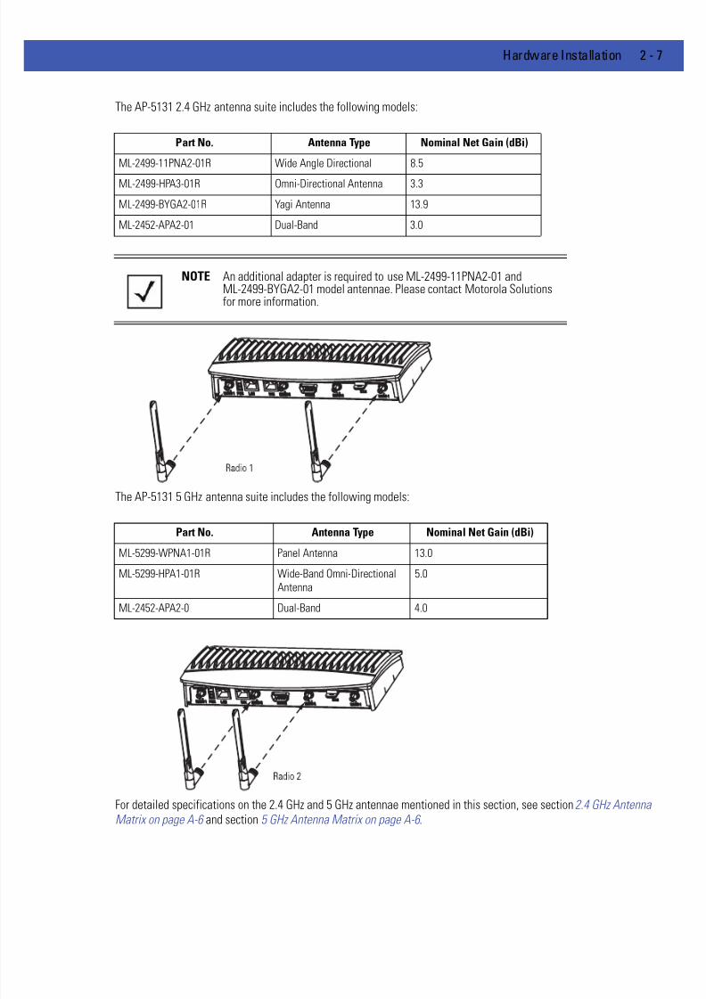
7/18/2019 Motorola AP 5131 Manual
http://slidepdf.com/reader/full/motorola-ap-5131-manual 41/613
Hardware Installation 2 - 7
The AP-5131 2.4 GHz antenna suite includes the following models:
The AP-5131 5 GHz antenna suite includes the following models:
For detailed specifications on the 2.4 GHz and 5 GHz antennae mentioned in this section, see section 2.4 GHz AntennaMatrix on page A-6 and section 5 GHz Antenna Matrix on page A-6 .
Part No. Antenna Type Nominal Net Gain (dBi)
ML-2499-11PNA2-01R Wide Angle Directional 8.5
ML-2499-HPA3-01R Omni-Directional Antenna 3.3
ML-2499-BYGA2-01R Yagi Antenna 13.9
ML-2452-APA2-01 Dual-Band 3.0
NOTE An additional adapter is required to use ML-2499-11PNA2-01 andML-2499-BYGA2-01 model antennae. Please contact Motorola Solutionsfor more information.
Part No. Antenna Type Nominal Net Gain (dBi)
ML-5299-WPNA1-01R Panel Antenna 13.0
ML-5299-HPA1-01R Wide-Band Omni-Directional
Antenna
5.0
ML-2452-APA2-0 Dual-Band 4.0

7/18/2019 Motorola AP 5131 Manual
http://slidepdf.com/reader/full/motorola-ap-5131-manual 42/613
2 - 8 WiNG 4.4 AP-5131 Product Reference Guide
2.4.2.2 AP-5181 Antenna Options
Both Radio 1 and Radio 2 require one antenna and can optimally use two antennae per radio (4 antennae total). Antennaconnectors for Radio 1 are located in a different location from the Radio 2 antenna connectors. Two antennae per radioprovides diversity that can improve performance and signal reception. Motorola Solutions supports two antenna suites for
the AP-5181. One antenna suite supporting the 2.4 GHz band and another antenna suite supporting the 5 GHz band. Selectan antenna model best suited to the intended operational environment of your AP-5181.
Refer to the following for the antenna options available to an AP-5181 model access point:
The AP-5181 2.4 GHz antenna suite includes the following models:
The AP-5181 5 GHz antenna suite includes the following models:
Part Number Antenna TypeNominal Net Gain
(dBi) Description
ML-2499-FHPA5-01R Omni-Directional Antenna 5.0 2.4 GHz,
Type N connector,
no pigtail
ML-2499-FHPA9-01R Omni-Directional Antenna 9.0 2.4 GHz,Type N connector,
no pigtail
ML-2452-PNA7-01R Panel Antenna (Dual-Band) 8.0 2.4 - 2.5/4.9 - 5.99
GHz, 66 deg/60 deg
Type N connector,
with pigtail
ML-2452-PNA5-01R Sector Antenna (Dual-Band) 6.0 2.3 - 2.4/4.9 - 5.9 GHz,
120 deg Sector
Type N connector,
with pigtail
Part Number Antenna TypeNominal Net Gain
(dBi) Description
ML-5299-FHPA6-01R Omni-Directional Antenna 7.0 4.900-5.850 GHz,
Type N connector,
no pigtail
ML-5299-FHPA10-01R Omni-Directional Antenna 10.0 5.8 GHz,
Type N connector,
no pigtail

7/18/2019 Motorola AP 5131 Manual
http://slidepdf.com/reader/full/motorola-ap-5131-manual 43/613
Hardware Installation 2 - 9
2.5 Power Options
2.5.1 AP-5131 Power Options
The power options for the AP-5131 include:
• Power Injector (Part No. AP-PSBIAS-1P2-AFR)
• 48-Volt Power Supply (Part No. 50-14000-243R)
• Any 802.3af midspan device.
2.5.2 AP-5181 Power Options
The power options for the AP-5181 include:
• Power Injector (Part No. AP-PSBIAS-1P2-AFR)
• Power Tap (Part No. AP-PSBIAS-5181-01R)
• Any 802.3af midspan device.
CAUTION An AP-5181 model access point cannot use the AP-5131recommended 48-Volt Power Supply (Part No. 50-14000-243R).
Motorola Solutions recommends the AP-PSBIAS-5181-01R Power Tapfor use an AP-5181 and its intended outdoor deployment.
7/18/2019 Motorola AP 5131 Manual
http://slidepdf.com/reader/full/motorola-ap-5131-manual 44/613
2 - 10 WiNG 4.4 AP-5131 Product Reference Guide
2.6 Power Injector and Power Tap Systems
An AP-5131 or AP-5181 access point can receive power via an Ethernet cable connected to the access point’s LAN port(using 802.3af). When users purchase a WLAN solution, they often need to place access points in obscure locations. In thepast, a dedicated power source was required for each access point in addition to the Ethernet infrastructure. This oftenrequired an electrical contractor to install power drops at each access point location.
The Power Injector and Power Tap solutions merge power and Ethernet into one cable, reducing the burden of installationand allow optimal access point placement in respect to the intended radio coverage area.
Both the Power Injector and Power Tap are integrated AC-DC converters requiring 110-220 VAC power to combine low-voltage DC with Ethernet data in a single cable connecting to the access point. The access point can only use a PowerInjector or Power Tap when connecting the unit to the access point’s LAN port. The Power Injector (Part No. AP-PSBIAS-1P2-AFR) is included in certain AP-5131 kits. The AP-5181 Power Tap (Part No. AP-PSBIAS-5181-01R) is ordered separatelyand is intended for AP-5181 outdoor deployments.
A separate Power Injector or Power Tap is required for each access point comprising the network.
2.6.1 Installing the Power Injector or Power Tap
Refer to the following sections for information on planning, installing, and validating the installation:
• Preparing for Site Installation
• Cabling the Power Injector and Power Tap
• Power Injector LED Indicators
2.6.1.1 Preparing for Site Installation
The Power Injector or Power Tap can be installed free standing, on an even horizontal surface or wall mounted using theunit’s wall mounting key holes. The following guidelines should be adhered to before cabling the Power Injector or PowerTap to an Ethernet source and an access point:
• Do not block or cover airflow to the Power Injector or Power Tap.
• Keep the unit away from excessive heat, humidity, vibration and dust.
• The Power Injector and Power Tap are not repeaters, and do not amplify the Ethernet data signal. For optimalperformance, ensure the unit is placed as close as possible to the network data port.
2.6.1.2 Cabling the Power Injector and Power Tap
To install a Power Injector or Power Tap to an Ethernet data source and access point:
NOTE Though an AP-5181 can use the Power Injector solution (Part No. AP-
PSBIAS-1P2-AFR), Motorola Solutions recommends using the AP-5181Power Tap (Part No. AP-PSBIAS-5181-01R) designed especially foroutdoor deployments.
CAUTION The access point supports a 802.3af compliant power source(including non-Motorola Solutions power sources). However, using thewrong solution (including a POE system used on a legacy MotorolaSolutions access point) could severely damage the access point andvoid the product warranty.

7/18/2019 Motorola AP 5131 Manual
http://slidepdf.com/reader/full/motorola-ap-5131-manual 45/613
Hardware Installation 2 - 11
1. Connect an RJ-45 Ethernet cable between the network data supply (host) and the Power Injector’s Data In or the Power Tap’sDATA IN connector.
2. Connect an RJ-45 Ethernet cable between the Power Injector’s Data & Power Out connector or the Power Tap’s DATA/ PWR OUT connector and the access point’s LAN port.
Ensure the cable length from the Ethernet source (host) to the Power Tap (or Power Injector) and access point does not exceed100 meters (333 ft). Neither the Power Tap or Power Injector has an On/Off switch. Each receives power as soon as AC poweris applied.
3. For Power Tap installations, have a certified electrician open the Power Tap enclosure, feed the power cable through theunit’s LINE AC connector, secure the power cable to the unit’s three screw termination block and tighten the unit’s LINE ACclamp (by hand) to ensure the power cable cannot be pulled from the unit and is protected from the elements.
4. For Power Tap installations, attach a ground cable between the EARTH GROUND connector (on the back of the unit) to asuitable earth ground connection as defined by your local electrical code.
5. Verify all cable connections are complete before supplying power to the access point.
2.6.1.3 Power Injector LED Indicators
The Power Injector demonstrates the following LED behavior under normal and/or problematic operating conditions:
For more information and device specifications for the Power Injector, refer to the Power Injector Quick Install Guide (PartNo. 72-70762-01) available from the Motorola Solutions Web site.
CAUTION For Power Tap installations, an electrician is required to open thePower Tap unit, feed the power cable through the Line AC connector,secure the power cable to the unit’s three screw termination block andtighten the unit’s Line AC clamp (by hand) to ensure the power cablecannot be pulled from the Power Tap enclosure. Only a certifiedelectrician should conduct the installation.
CAUTION Ensure AC power is supplied to the Power Injector or Power Tap (forAP-5181 installations) using an AC cable with an appropriate groundconnection approved for the country of operation.
CAUTION Cabling the Power Injector to the access point’s WAN port renders theaccess point non-operational. Only use a Power Injector or Power Tapwith the access point’s LAN port.
NOTE The AP-5181 Power Tap (Part No. AP-PSBIAS-5181-01R) does not haveLED indicators.
LED AC (Main) Port
Green (Steady) Power Injector is receiving power from an
AC outlet.
Indicates a device is connected to the
Power Injector’s outgoing Data & Power
cable.
Green (Blinking) Output voltage source is out of range. The Power Injector is overloaded or has a
short circuit.
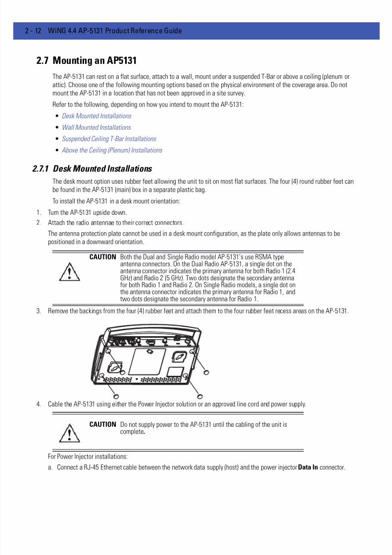
7/18/2019 Motorola AP 5131 Manual
http://slidepdf.com/reader/full/motorola-ap-5131-manual 46/613
2 - 12 WiNG 4.4 AP-5131 Product Reference Guide
2.7 Mounting an AP5131
The AP-5131 can rest on a flat surface, attach to a wall, mount under a suspended T-Bar or above a ceiling (plenum orattic). Choose one of the following mounting options based on the physical environment of the coverage area. Do notmount the AP-5131 in a location that has not been approved in a site survey.
Refer to the following, depending on how you intend to mount the AP-5131:
• Desk Mounted Installations
• Wall Mounted Installations
• Suspended Ceiling T-Bar Installations
• Above the Ceiling (Plenum) Installations
2.7.1 Desk Mounted Installations
The desk mount option uses rubber feet allowing the unit to sit on most flat surfaces. The four (4) round rubber feet canbe found in the AP-5131 (main) box in a separate plastic bag.
To install the AP-5131 in a desk mount orientation:
1. Turn the AP-5131 upside down.
2. Attach the radio antennae to their correct connectors.
The antenna protection plate cannot be used in a desk mount configuration, as the plate only allows antennas to bepositioned in a downward orientation.
3. Remove the backings from the four (4) rubber feet and attach them to the four rubber feet recess areas on the AP-5131.
4. Cable the AP-5131 using either the Power Injector solution or an approved line cord and power supply.
For Power Injector installations:
a. Connect a RJ-45 Ethernet cable between the network data supply (host) and the power injector Data In connector.
CAUTION Both the Dual and Single Radio model AP-5131’s use RSMA typeantenna connectors. On the Dual Radio AP-5131, a single dot on theantenna connector indicates the primary antenna for both Radio 1 (2.4GHz) and Radio 2 (5 GHz). Two dots designate the secondary antennafor both Radio 1 and Radio 2. On Single Radio models, a single dot on
the antenna connector indicates the primary antenna for Radio 1, andtwo dots designate the secondary antenna for Radio 1.
CAUTION Do not supply power to the AP-5131 until the cabling of the unit iscomplete.

7/18/2019 Motorola AP 5131 Manual
http://slidepdf.com/reader/full/motorola-ap-5131-manual 47/613
Hardware Installation 2 - 13
b. Connect a RJ-45 Ethernet cable between the Power Injector Data & Power Out connector and the AP-5131 LAN port.
c. Ensure the cable length from the Ethernet source (host) to the Power Injector and AP-5131 does not exceed 100 meters(333 ft). The Power Injector has no On/Off power switch. The Power Injector receives power as soon as AC power isapplied. For more information on using the Power Injector, see Power Injector and Power Tap Systems on page 2-10 .
For standard 48-Volt power adapter (Part No. 50-14000-243R) and line cord installations:a. Connect RJ-45 Ethernet cable between the network data supply (host) and the AP-5131 LAN port.
b. Verify the power adapter is correctly rated according the country of operation.
c. Connect the power supply line cord to the power adapter.
d. Attach the power adapter cable into the power connector on the AP-5131.
e. Plug the power adapter into an outlet.
5. Verify the behavior of the AP-5131 LEDs. For more information, seeAP-5131 LED Indicators on page 2-19 .
6. Return the AP-5131 to an upright position and place it in the location you wish it to operate. Ensure the AP-5131 is sittingevenly on all four rubber feet.
The AP-5131 is ready to configure. For information on an AP-5131 default configuration, see Getting Started on page 3-1.For specific details on AP-5131 system configurations, see System Configuration on page 4-1.
2.7.2 Wall Mounted Installations
Wall mounting requires hanging the AP-5131 along its width (or length) using the pair of slots on the bottom of the unitand using the AP-5131 itself as a mounting template for the screws. The AP-5131 can be mounted onto any plaster or woodwall surface.
The mounting hardware and tools (customer provided) required to install the AP-5131 on a wall consists of:
• Two Phillips pan head self-tapping screws (ANSI Standard) #6-18 X 0.875in. Type A or AB Self-Tapping screw, or (ANSIStandard Metric) M3.5 X 0.6 X 20mm Type D Self-Tapping screw
• Two wall anchors
• Security cable (optional)
To mount the AP-5131 on a wall:
1. Orient the AP-5131 on the wall by its width or length.
2. Using the arrows on one edge of the case as guides, move the edge to the midline of the mounting area and mark points onthe midline for the screws.
3. At each point, drill a hole in the wall, insert an anchor, screw into the anchor the wall mounting screw and stop when thereis 1mm between the screw head and the wall.
If pre-drilling a hole, the recommended hole size is 2.8mm (0.11in.) if the screws are going directly into the wall and 6mm
(0.23in.) if wall anchors are being used.4. If required, install and attach a security cable to the AP-5131 lock port.
5. Place the large corner of each of the mount slots over the screw heads.
6. Slide the AP-5131 down along the mounting surface to hang the mount slots on the screw heads.
7. Attach the radio antennae to their correct connectors.
7/18/2019 Motorola AP 5131 Manual
http://slidepdf.com/reader/full/motorola-ap-5131-manual 48/613
2 - 14 WiNG 4.4 AP-5131 Product Reference Guide
8. Cable the AP-5131 using either the Power Injector solution or an approved line cord and power supply.
For Power Injector installations:
a. Connect a RJ-45 Ethernet cable between the network data supply (host) and the Power Injector Data In connector.
b. Connect a RJ-45 Ethernet cable between the Power Injector Data & Power Out connector and the AP-5131 LAN port.
c. Ensure the cable length from the Ethernet source (host) to the Power Injector and AP-5131 does not exceed 100 meters(333 ft). The Power Injector has no On/Off power switch. The Power Injector receives power as soon as AC power isapplied. For more information on using the Power Injector, see Power Injector and Power Tap Systems on page 2-10 .
For standard 48-Volt Power Adapter (Part No. 50-14000-243R) and line cord installations:
a. Connect RJ-45 Ethernet cable between the network data supply (host) and the AP-5131 LAN port.
b. Verify the power adapter is correctly rated according the country of operation.c. Connect the power supply line cord to the power adapter.
d. Attach the power adapter cable into the power connector on the AP-5131.
e. Plug the power adapter into an outlet.
9. Verify the behavior of the AP-5131 LEDs. For more information, see AP-5131 LED Indicators on page 2-19 .
The AP-5131 is ready to configure. For information on an AP-5131 default configuration, see Getting Started on page 3-1.For specific details on AP-5131 system configurations, see System Configuration on page 4-1.
2.7.3 Suspended Ceiling T-Bar Installations
A suspended ceiling mount requires holding the AP-5131 up against the T-bar of a suspended ceiling grid and twisting theAP-5131 chassis onto the T-bar.
The mounting hardware and tools (customer provided) required to install the AP-5131 on a ceilingT-bar consists of:
• Safety wire (recommended)
CAUTION Both the Dual and Single Radio model AP-5131s use RSMA typeantenna connectors. On the Dual Radio AP-5131, a single dot on theantenna connector indicates the primary antenna for both Radio 1 (2.4GHz) and Radio 2 (5 GHz). Two dots designate the secondary antennafor both Radio 1 and Radio 2. On Single Radio models, a single dot onthe antenna connector indicates the primary antenna for Radio 1, andtwo dots designate the secondary antenna for Radio 1.
NOTE The access point must be mounted with the RJ45 cable connectororiented upwards to ensure proper operation.
CAUTION Do not supply power to the AP-5131 until the cabling of the unit iscomplete.
NOTE If the AP-5131 is utilizing remote management antennae, a wire covercan be used to provide a clean finished look to the installation. ContactMotorola Solutions for more information.

7/18/2019 Motorola AP 5131 Manual
http://slidepdf.com/reader/full/motorola-ap-5131-manual 49/613
Hardware Installation 2 - 15
• Security cable (optional)
To install the AP-5131 on a ceiling T-bar:
1. If required, loop a safety wire —with a diameter of at least 1.01 mm (.04 in.), but no more than 0.158 mm (.0625 in.) —through the tie post (above the AP-5131’s console connector) and secure the loop.
2. If required, install and attach a security cable to the AP-5131 lock port.
3. Attach the radio antennae to their correct connectors.
4. Cable the AP-5131 using either the Power Injector solution or an approved line cord and power supply.
For Power Injector installations:
a. Connect a RJ-45 Ethernet cable between the network data supply (host) and the Power Injector Data In connector.
b. Connect a RJ-45 Ethernet cable between the Power Injector Data & Power Out connector and the AP-5131 LAN port.
c. Ensure the cable length from the Ethernet source (host) to the Power Injector and AP-5131 does not exceed 100 meters(333 ft). The Power Injector has no On/Off power switch. The Power Injector receives power as soon as AC power isapplied. For more information on using the Power Injector, see Power Injector and Power Tap Systems on page 2-10 .
For standard 48-Volt Power Adapter (Part No. 50-14000-243R) and line cord installations:a. Connect RJ-45 Ethernet cable between the network data supply (host) and the AP-5131 LAN port.
b. Verify the power adapter is correctly rated according the country of operation.
c. Connect the power supply line cord to the power adapter.
d. Attach the power adapter cable into the power connector on the AP-5131.
e. Plug the power adapter into an outlet.
5. Verify the behavior of the AP-5131 LEDs. For more information, see AP-5131 LED Indicators on page 2-19 .
6. Align the bottom of the ceiling T-bar with the back of the AP-5131.
7. Orient the AP-5131 chassis by its length and the length of the ceiling T-bar.
8. Rotate the AP-5131 chassis 45 degrees clockwise, or about 10 o’clock.
9. Push the back of the AP-5131 chassis on to the bottom of the ceiling T-bar.
10. Rotate the AP-5131 chassis 45 degrees counter-clockwise. The clips click as they fasten to the T-bar.
CAUTION Both the Dual and Single Radio model AP-5131s use RSMA typeantenna connectors. On a Dual Radio AP-5131, a single dot on theantenna connector indicates the primary antenna for both Radio 1 (2.4GHz) and Radio 2 (5 GHz). Two dots designate the secondary antennafor both Radio 1 and Radio 2. On Single Radio models, a single dot onthe antenna connector indicates the primary antenna for Radio 1, andtwo dots designate the secondary antenna for Radio 1
CAUTION Do not supply power to the AP-5131 until the cabling of the unit iscomplete.
CAUTION Ensure the safety wire and cabling used in the T-Bar AP-5131installation is securely fastened to the building structure in order toprovide a safe operating environment.

7/18/2019 Motorola AP 5131 Manual
http://slidepdf.com/reader/full/motorola-ap-5131-manual 50/613
2 - 16 WiNG 4.4 AP-5131 Product Reference Guide
11. The AP-5131 is ready to configure. For information on an AP-5131 default configuration, see Getting Started on page 3-1.For specific details on AP-5131 system configurations, see System Configuration on page 4-1.
2.7.4 Above the Ceiling (Plenum) Installations
An AP-5131 above the ceiling installation requires placing the AP-5131 above a suspended ceiling and installing theprovided light pipe under the ceiling tile for viewing the rear panel status LEDs of the unit. An above the ceiling AP-5131
installation enables installations compliant with drop ceilings, suspended ceilings and industry standard tiles from .625 to.75 inches thick.
The mounting hardware required to install the AP-5131 above a ceiling consists of:
• Light pipe
• Badge for light pipe
• Decal for badge
• Safety wire (strongly recommended)
• Security cable (optional)
NOTE If the AP-5131 is utilizing remote management antennae, a wire covercan be used to provide a clean finished look to the installation. ContactMotorola Solutions for more information.
NOTE The AP-5131 is Plenum rated to UL2043 and NEC1999 to support abovethe ceiling installations.
CAUTION Motorola Solutions does not recommend mounting the AP-5131directly to any suspended ceiling tile with a thickness less than12.7mm (0.5in.) or a suspended ceiling tile with an unsupported spangreater than 660mm (26in.). Motorola Solutions strongly recommendsfitting the AP-5131 with a safety wire suitable for supporting theweight of the device. The safety wire should be a standard ceilingsuspension cable or equivalent steel wire between 1.59mm (.062in.)and 2.5mm (.10in.) in diameter.

7/18/2019 Motorola AP 5131 Manual
http://slidepdf.com/reader/full/motorola-ap-5131-manual 51/613
Hardware Installation 2 - 17
To install the AP-5131 above a ceiling:
1. If possible, remove the adjacent ceiling tile from its frame and place it aside.
2. Install a safety wire, between 1.5mm (.06in.) and 2.5mm (.10in.) in diameter, in the ceiling space.
3. If required, install and attach a security cable to the AP-5131’s lock port.
4. Mark a point on the finished side of the tile where the light pipe is to be located.
5. Create a light pipe path hole in the target position on the ceiling tile.
6. Use a drill to make a hole in the tile the approximate size of the AP-5131 LED light pipe.
7. Remove the light pipe’s rubber stopper before installing the light pipe.
8. Connect the light pipe to the bottom of the AP-5131. Align the tabs and rotate approximately 90 degrees. Do not over tighten
9. Snap the clips of the light pipe into the bottom of the AP-5131.
10. Fit the light pipe into hole in the tile from its unfinished side.
11. Place the decal on the back of the badge and slide the badge onto the light pipe from the finished side of the tile.
12. Attach the radio antennae to their correct connectors.
13. Attach safety wire (if used) to the AP-5131 safety wire tie point or security cable (if used) to the AP-5131’s lock port.
14. Align the ceiling tile into its former ceiling space.
15. Cable the AP-5131 using either the Power Injector solution or an approved line cord and power supply.
CAUTION Motorola Solutions recommends care be taken not to damage thefinished surface of the ceiling tile when creating the light pipe holeand installing the light pipe.
CAUTION Both the Dual and Single Radio model AP-5131s use RSMA typeantenna connectors. On the Dual Radio AP-5131, a single dot on theantenna connector indicates the primary antenna for both Radio 1 (2.4GHz) and Radio 2 (5 GHz). Two dots designate the secondary antennafor both Radio 1 and Radio 2. On Single Radio models, a single dot onthe antenna connector indicates the primary antenna for Radio 1, andtwo dots designate the secondary antenna for Radio 1.
Light Pipe
Decal
Badge
Ceiling Tile

7/18/2019 Motorola AP 5131 Manual
http://slidepdf.com/reader/full/motorola-ap-5131-manual 52/613
2 - 18 WiNG 4.4 AP-5131 Product Reference Guide
For Power Injector installations:
a. Connect a RJ-45 Ethernet cable between the network data supply (host) and the Power Injector Data In connector.
b. Connect a RJ-45 Ethernet cable between the Power Injector Data & Power Out connector and the AP-5131 LAN port.
c. Ensure the cable length from the Ethernet source (host) to the Power Injector and AP-5131 does not exceed 100 meters(333 ft). The Power Injector has no On/Off power switch. The Power Injector receives power as soon as AC power isapplied. For more information on using the Power Injector, see Power Injector and Power Tap Systems on page 2-10 .
For standard 48-Volt Power Adapter (Part No. 50-14000-243R) and line cord installations:
a. Connect a RJ-45 Ethernet cable between the network data supply (host) and the AP-5131 LAN port.
b. Verify the power adapter is correctly rated according the country of operation.
c. Connect the power supply line cord to the power adapter.d. Attach the power adapter cable into the power connector on the AP-5131.
e. Plug the power adapter into an outlet.
16. Verify the behavior of the AP-5131 LED lightpipe. For more information, see AP-5131 LED Indicators on page 2-19 .
17. Place the ceiling tile back in its frame and verify it is secure.
The AP-5131 is ready to configure. For information on an AP-5131 default configuration, see Getting Started on page 3-1.For specific details on AP-5131 system configurations, see System Configuration on page 4-1.
CAUTION Do not supply power to the AP-5131 until the cabling of the unit iscomplete.

7/18/2019 Motorola AP 5131 Manual
http://slidepdf.com/reader/full/motorola-ap-5131-manual 53/613
Hardware Installation 2 - 19
2.8 AP-5131 LED Indicators
The AP-5131 utilizes seven LED indicators. Five LEDs display within four LED slots on the front of the AP-5131 (on top ofthe AP-5131 housing) and two LEDs (for above the ceiling installations) are located on the back of the device (the sidecontaining the LAN, WAN and antenna connectors).
The five LEDs on the top housing of the AP-5131 are clearly visible in table-top, wall and below ceiling installations. Thefive AP-5131 top housing LEDs have the following display and functionality:
The LEDs on the rear of the AP-5131 are viewed using a single (customer installed) extended lightpipe, adjusted asrequired to suit above the ceiling installations. The LEDs displayed using the lightpipe have the following color display and
functionality:
Power Status Solid white indicates the AP-5131 is adequately powered.
Error Conditions
Solid red indicates the AP-5131 is experiencing a problem condition requiring
immediate attention.
Ethernet Activity Flashing white indicates data transfers and Ethernet activity.
802.11a Radio Activity
Flickering amber indicates beacons and data transfers over the AP-5131
802.11a radio.
802.11b/g Radio Activity
Flickering green indicates beacons and data transfers over the AP-5131
802.11b/g radio.
Boot and Power Status Solid white indicates the AP-5131 is adequately powered.
Error Conditions
Solid red indicates the AP-5131 is experiencing a problem condition requiring
immediate attention.
Power and ErrorConditions
Blinking red indicates the AP-5131 Rogue AP Detection feature has located a
rogue device

7/18/2019 Motorola AP 5131 Manual
http://slidepdf.com/reader/full/motorola-ap-5131-manual 54/613
2 - 20 WiNG 4.4 AP-5131 Product Reference Guide
2.9 Mounting an AP5181
The AP-5181 can be connected to a pole or attach to a wall. Choose one of the following mounting options based on thephysical environment of the coverage area. Do not mount the AP-5181 in a location that has not been approved in a sitesurvey.
Refer to the following, depending on how you intend to mount the AP-5181:
• AP-5181 Pole Mounted Installations
• AP-5181 Wall Mounted Installations
2.9.1 AP-5181 Pole Mounted Installations
Complete the following steps to mount the AP-5181 to a (1.5 to 18 inch diameter) steel pole or tube (using the mountingbracket):
1. Fit the edges of the V-shaped clamp parts into the slots on the flat side of the rectangular plate.
2. Place the V-shaped bracket clamp parts around the pole and tighten the nuts just enough to hold the bracket to the pole.
(The bracket may need to be rotated around the pole during the antenna alignment process).
3. Attach the square mounting plate to the bridge with the supplied screws.
4. Attach the AP-5181 and mounting plate to the bracket already fixed to the pole.
5. Secure the AP-5181 to the pole bracket using the provided nuts.
Fit the edges of the V-shaped part into the slots
Tighten the
securing bolts
Attach the squareplate to the bridge

7/18/2019 Motorola AP 5131 Manual
http://slidepdf.com/reader/full/motorola-ap-5131-manual 55/613
Hardware Installation 2 - 21
6. Attach the radio antenna to their correct connectors.
7. Cable the AP-5181 using either the AP-5181 Power Tap (Part No. AP-PSBIAS-5181-01R) or the Power Injector (Part No. AP-PSBIAS-1P2-AFR).
a. Connect a RJ-45 Ethernet cable between the network data supply (host) and the Power Tap’s DATA IN connector or thePower Injector’s Data In connector.
b. Connect a RJ-45 Ethernet cable between the Power Tap’s DATA/PWR OUT connector or the Power Injector’s Data &
Power Out connector and the AP-5181 LAN port.
c. For Power Tap installations, have a certified electrician open the Power Tap enclosure, feed the power cable through theunit’s LINE AC connector, secure the power cable to the unit’s three screw termination block and tighten the unit’s LINEAC clamp (by hand) to ensure the power cable cannot be pulled from the unit.
d. For Power Tap installations, attach a ground cable between the EARTH GROUND connector (on the back of the unit) toa suitable earth ground connection as defined by your local electrical code.
e. Ensure the cable length from the Ethernet source (host) to the Power Tap (or Power Injector) and AP-5181 does not exceed100 meters (333 ft). Neither the Power Tap or Power injector has an On/Off power switch. Each receives power as soonas AC power is applied. For more information on using the see, Power Injector and Power Tap Systems on page 2-10 .
8. Use the supplied cable connector to cover the AP-5181’s Console, LAN/PoE and WAN connectors.
9. Once power has been applied, Verify the behavior of the AP-5181 LEDs. For more information, see AP5181 LED Indicators onpage 2-24 .
The AP-5181 is ready to configure. For information on an AP-5181 default configuration, see Getting Started on page 3-1.For specific details on AP-5131 system configurations, see System Configuration on page 4-1.
NOTE The AP-5181 tilt angle may need to be adjusted during the antennaalignment process. Verify the antenna polarization angle when installing,ensure the antennas are oriented correctly in respect to the AP-5181'scoverage area.
NOTE The access point must be mounted with the RJ45 cable connectorsoriented upwards to ensure proper operation.
CAUTION Do not supply power to the AP-5181 Power Tap or Power Injector untilthe cabling of the access point is complete.
CAUTION For Power Tap installations, an electrician is required to open thePower Tap unit, feed the power cable through the Line AC connector,secure the power cable to the unit’s three screw termination block andtighten the unit’s Line AC clamp (by hand) to ensure the power cablecannot be pulled from the Power Tap enclosure. Only a certifiedelectrician should conduct the installation.
NOTE If installing the AP-5181 in an outdoor area prone to high winds and rain,Motorola Solutions recommends using the AP-5181 Heavy Weather Kit(Part No. KT-5181-HW-01R). This kit shields an AP-5181 from high windsand water damage as a result of driving rain.

7/18/2019 Motorola AP 5131 Manual
http://slidepdf.com/reader/full/motorola-ap-5131-manual 56/613
2 - 22 WiNG 4.4 AP-5131 Product Reference Guide
2.9.2 AP-5181 Wall Mounted Installations
Complete the following steps to mount the AP-5181 to a wall using the supplied wall-mounting bracket:
1. Attach the bracket to a wall with flat side flush against the wall (see the illustration below). Position the bracket in theintended location and mark the positions of the four mounting screw holes.
2. Drill four holes in the wall that match the screws and wall plugs.
3. Secure the bracket to the wall.
4. Attach the square mounting plate to the bridge with the supplied screws. Attach the bridge to the plate on the pole.
5. Use the included nuts to tightly secure the wireless bridge to the bracket. Fit the edges of the V-shaped clamp into the slotson the flat side of the rectangular plate.
6. Attach the radio antenna to their correct connectors.
7. Cable the AP-5181 using either the AP-5181 Power Tap (Part No. AP-PSBIAS-5181-01R) or the Power Injector (Part No. AP-PSBIAS-1P2-AFR).
NOTE Once ready for the final positioning of the access point, ensure the RJ45cable connectors are oriented upwards to ensure proper operation.
CAUTION Do not supply power to the AP-5181 Power Tap or Power Injector untilthe cabling of the access point is complete.
7/18/2019 Motorola AP 5131 Manual
http://slidepdf.com/reader/full/motorola-ap-5131-manual 57/613
Hardware Installation 2 - 23
a. Connect a RJ-45 Ethernet cable between the network data supply (host) and the Power Tap’s DATA IN connector or thePower Injector’s Data In connector.
b. Connect a RJ-45 Ethernet cable between the Power Tap’s DATA/PWR OUT connector or the Power Injector’s Data &Power Out connector and the AP-5181 LAN port.
c. For Power Tap installations, have a certified electrician open the Power Tap enclosure, feed the power cable through theunit’s LINE AC connector, secure the power cable to the unit’s three screw termination block and tighten the unit’s LINEAC clamp (by hand) to ensure the power cable cannot be pulled from the unit.
d. For Power Tap installations, attach a ground cable between the EARTH GROUND connector (on the back of the unit) toa suitable earth ground connection as defined by your local electrical code.
e. Ensure the cable length from the Ethernet source (host) to the Power Tap (or Power Injector) and AP-5181 does not exceed100 meters (333 ft). Neither the Power Tap or Power injector has an On/Off power switch. Each receives power as soonas AC power is applied. For more information on using the see, Power Injector and Power Tap Systems on page 2-10 .
8. Use the supplied cable connector to cover the AP-5181’s Console, LAN/PoE and WAN connectors.
9. Once power has been applied, Verify the behavior of the AP-5181 LEDs. For more information, see AP5181 LED Indicators onpage 2-24 .
The AP-5181 is ready to configure. For information on an AP-5181 default configuration, see Getting Started on page 3-1.For specific details on AP-5131 system configurations, see System Configuration on page 4-1.
CAUTION For Power Tap installations, an electrician is required to open thePower Tap unit, feed the power cable through the Line AC connector,secure the power cable to the unit’s three screw termination block andtighten the unit’s Line AC clamp (by hand) to ensure the power cablecannot be pulled from the Power Tap enclosure. Only a certifiedelectrician should conduct the installation.
NOTE If installing the AP-5181 in an outdoor area prone to high winds and rain,Motorola Solutions recommends using the AP-5181 Heavy Weather Kit
(Part No. KT-5181-HW-01R). This kit shields an AP-5181 from high windsand water damage as a result of driving rain.

7/18/2019 Motorola AP 5131 Manual
http://slidepdf.com/reader/full/motorola-ap-5131-manual 58/613
2 - 24 WiNG 4.4 AP-5131 Product Reference Guide
2.10 AP5181 LED Indicators
The AP-5181 utilizes four LED indicators. Five LEDs display within four LED slots on the back of the access point. The fiveLEDs have the following display and functionality:
Power Status Solid white indicates the access point is adequately powered.
Error Conditions
Solid red indicates the access point is experiencing a problem condition
requiring immediate attention.
Ethernet Activity Flashing white indicates data transfers and Ethernet activity.
802.11a Radio Activity
Flickering amber indicates beacons and data transfers over the access point
802.11a radio.
802.11b/g Radio Activity
Flickering green indicates beacons and data transfers over the access point
802.11b/g radio.
Power and error conditions (split LED)
Data over Ethernet
802.11a radio activity
802.11b/g radio activity

7/18/2019 Motorola AP 5131 Manual
http://slidepdf.com/reader/full/motorola-ap-5131-manual 59/613
Hardware Installation 2 - 25
2.11 Setting Up MUs
For a discussion of how to initially test the access point to ensure it can interoperate with the MUs intended for itsoperational environment, see Basic Device Configuration on page 3-6 and specifically Testing Connectivity on page 3-11
Refer to the LA-5030 & LA-5033 Wireless Networker PC Card and PCI Adapter Users Guide, available from the MotorolaSolutions Web site, for installing drivers and client software if operating in an 802.11a/g network environment.
Refer to the Spectrum24 LA-4121 PC Card, LA-4123 PCI Adapter & LA-4137 Wireless Networker User Guide, available fromthe Motorola Solutions Web site, for installing drivers and client software if operating in an 802.11b network environment.
Use the default values for the ESSID and other configuration parameters until the network connection is verified. MUsattach to the network and interact with the AP transparently.

7/18/2019 Motorola AP 5131 Manual
http://slidepdf.com/reader/full/motorola-ap-5131-manual 60/613
2 - 26 WiNG 4.4 AP-5131 Product Reference Guide
7/18/2019 Motorola AP 5131 Manual
http://slidepdf.com/reader/full/motorola-ap-5131-manual 61/613
CHAPTER 3 GETTING STARTED
The access point should be installed in an area tested for radio coverage using one of the site survey tools available to thefield service technician. Once an installation site has been identified, the installer should carefully follow the hardwareprecautions, requirements, mounting guidelines and power options outlined in Hardware Installation .
See the following sections for more details:
• Installing the Access Point
• Configuration Options
• Basic Device Configuration

7/18/2019 Motorola AP 5131 Manual
http://slidepdf.com/reader/full/motorola-ap-5131-manual 62/613
3 - 2 WiNG 4.4 AP-5131 Product Reference Guide
3.1 Installing the Access Point
Make the required cable and power connections before mounting the access point in its final operating position. Test theaccess point with an associated MU before mounting and securing the access point. Carefully follow the mountinginstructions in one of the following sections to ensure the access point is installed correctly:
For installing an AP-5131 model access point
• For instructions on installing the AP-5131 on a table top, see Desk Mounted Installations on page 2-12 .
• For instructions on mounting an AP-5131 to a wall, see Wall Mounted Installations on page 2-13 .
• For instructions on mounting an AP-5131 to a ceiling T-bar, see Suspended Ceiling T-Bar Installations on page 2-14 .
• For instructions on installing the AP-5131 in an above the ceiling attic space, see Above the Ceiling (Plenum)Installations on page 2-16 .
For installing an AP-5181 model access point:
• For instructions on installing the AP-5181 to a pole, see AP-5181 Pole Mounted Installations on page 2-20 .
• For instructions on installing the AP-5181 to a wall, see AP-5181 Wall Mounted Installations on page 2-22 .For information on the 802.11a and 802.11b/g radio antenna suite available to the AP-51x1, see Antenna Options on page2-6 . For more information on using a Power Injector to combine Ethernet and power in one cable to an AP-5131 modelaccess point, see Power Injector and Power Tap Systems on page 2-10 . To verify AP-5131 LED behavior once installed, seeAP-5131 LED Indicators on page 2-19 . To verify the behavior of the AP-5181 LEDs once installed, see AP5181 LED Indicatorson page 2-24 .

7/18/2019 Motorola AP 5131 Manual
http://slidepdf.com/reader/full/motorola-ap-5131-manual 63/613
Getting Started 3 - 3
3.2 Configuration Options
Once installed and powered, an AP-5131 or AP-5181 can be configured using one of several connection techniques.Managing the AP-51x1 includes viewing network statistics and setting configuration options. The AP-51x1 requires one ofthe following connection methods to manage the network:
• Secure Java-Based WEB UI - (use Sun Microsystems’ JRE 1.5 or higher available from Sun’s Web site. DisableMicrosoft’s Java Virtual Machine if installed). For information on using the Web UI to set AP-51x1 defaultconfiguration, see Basic Device Configuration on page 3-6 or chapters 4 through 7 of this guide.
• Command Line Interface (CLI) via Serial, Telnet and SSH. The access point CLI is accessed through the RS232 port, viaTelnet or SSH. The CLI follows the same configuration conventions as the device user interface with a few documentedexceptions. For details on using the CLI to manage the access point, see CLI Reference on page 8-1.
• Config file - Readable text file; Importable/Exportable via FTP, TFTP and HTTP. Configuration settings for an access pointcan be downloaded from the current configuration of another access point meeting the import/export requirements.For information on importing or exporting configuration files, see Importing/Exporting Configurations on page 4-39 .
• MIB (Management Information Base) accessing the AP-51x1 SNMP functions using a MIB Browser. The access point
download package contains the following 2 MIB files:
• Symbol-CC-WS2000-MIB-2.0
• Symbol-AP-5131-MIB (can be used for both an AP-5131 and AP-5181 model access point, an AP-5181 does not haveits own MIB)

7/18/2019 Motorola AP 5131 Manual
http://slidepdf.com/reader/full/motorola-ap-5131-manual 64/613
3 - 4 WiNG 4.4 AP-5131 Product Reference Guide
3.3 Default Configuration Changes for the Access Point
The following table illustrates the changes made to the access point default configuration from its initial 1.0 releasethrough this most recent 2.0 release.
Version 1.0 Version 1.1 Version 1.1.1.0& 1.1.2.0
Version 2.0 & 2.1
WAN DHCP client
Auto-Update Enabled
Static IP: 10.1.1.1
Static Mask: 255.0.0.0
Static IP: 10.1.1.1
Static Mask: 255.0.0.0
Static IP: 10.1.1.1
Static Mask: 255.0.0.0
LAN1 Static IP: 192.168.0.1
Static Mask:
255.255.255.0
DHCP Server Enabled
DHCP Client
Auto-Update Enabled
Default Gateway
Ethernet Port Enabled
DHCP Client
Auto-Update Enabled
Default Gateway
Ethernet Port Enabled
DHCP Client
Auto-Update Enabled
Default Gateway
Ethernet Port Enabled
LAN2 Not applicable in 1.0
release (no LAN2
support)
Static IP: 192.168.1.1
Static Mask:
255.255.255.0DHCP Server Enabled
Disabled Disabled
Access
via WAN
port
HTTPS, SSH, SNMP:
Enabled
HTTP, HTTPS, SSH,
SNMP, Telnet:
Enabled
HTTP, HTTPS, SSH,
SNMP, Telnet:
Enabled
HTTP, HTTPS, SSH,
SNMP, Telnet:
Enabled

7/18/2019 Motorola AP 5131 Manual
http://slidepdf.com/reader/full/motorola-ap-5131-manual 65/613
Getting Started 3 - 5
3.4 Initially Connecting to the Access Poin t
3.4.1 Connecting to the Access Point using the WAN Port
To initially connect to the access point using the access point’s WAN port:
1. Connect AC power to the access point, as Power-Over-Ether support is not available on the access point’s WAN port.
2. Start a browser and enter the access point’s static IP WAN address (10.1.1.1). The default password is “motorola.”
3. Refer to Basic Device Configuration on page 3-6 for instructions on the initial (basic) configuration of the access point.
3.4.2 Connecting to the Access Point using the LAN Port
To initially connect to the access point using the access point’s LAN port:
1. The LAN port default is set to DHCP. Connect the access point’s LAN port to a DHCP server.
The access point will receive its IP address automatically.
2. To view the IP address, connect one end of a null modem serial cable to the access point and the other end to the serial portof a computer running HyperTerminal or similar emulation program.
3. Configure the following settings:
• Baud Rate - 19200
• Data Bits - 8
• Stop Bits - 1
• No Parity
• No Flow Control
4. Press <ESC> or <Enter> to access the access point CLI.
5. Enter the default username of “admin” and the default password of “motorola.”
As this is the first time you are logging into the access point, you are prompted to enter a new password and set the county
code. Refer to Country Codes on page A-9 for a list of each available countries two digit country code.
6. At the CLI prompt (admin>), type “summary.”
The access point’s LAN IP address will display.
7. Using a Web browser, use the access point’s IP address to access the access point.
8. Refer to Basic Device Configuration on page 3-6 for instructions on the initial (basic) configuration of the access point.
NOTE The procedures described below assume this is the first time you are
connecting to either an AP-5131 or AP-5181 model access point.
NOTE If using an AP-5131 model access point, a null modem cable is required. Ifusing an AP-5181 model access point, an RJ-45 to Serial cable is requiredto make the connection.

7/18/2019 Motorola AP 5131 Manual
http://slidepdf.com/reader/full/motorola-ap-5131-manual 66/613
3 - 6 WiNG 4.4 AP-5131 Product Reference Guide
3.5 Basic Device Configuration
For the basic setup described in this section, the Java-based Web UI will be used to configure the access point. Use theaccess point’s LAN interface for establishing a link with the access point. Configure the access point as a DHCP client. Foroptimal screen resolution, set your screen resolution to 1024 x 768 pixels or greater.
1. Log in using admin as the default Username and motorola as the default Password. Use your new password if it has beenupdated from default.
There is no difference in the login method between the AP-5131 and AP-5181 model access points. However, each modeldisplays a login screen unique in appearance (with a different model name). Additionally, each model access point displaysa banner on top of each menu screen unique to the AP-5131 or AP-5181 model supported.
2. If the default login is successful, the Change Admin Password window displays. Change the password.
Enter the current password and a new admin password in fields provided. Click Apply. Once the admin password has beenupdated, a warning message displays stating the access point must be set to a country.
NOTE For optimum compatibility, use Sun Microsystems’ JRE 1.5 or higher(available from Sun’s Website), and be sure to disable Microsoft’s JavaVirtual Machine if installed.

7/18/2019 Motorola AP 5131 Manual
http://slidepdf.com/reader/full/motorola-ap-5131-manual 67/613
Getting Started 3 - 7
The export function will always export the encrypted Admin User password. The import function will import the AdminPassword only if the access point is set to factory default. If the access point is not configured to factory default settings,the Admin User password WILL NOT get imported.
3.5.1 Configuring Device Settings
Configure a set of minimum required device settings within the Quick Setup screen. The values defined within the QuickSetup screen are also configurable in numerous other locations within the menu tree. When you change the settings inthe Quick Setup screen, the values also change within the screen where these parameters also exist. Additionally, if thevalues are updated in these other screens, the values initially set within the Quick Setup screen will be updated.
To define a basic access point configuration:
1. Select System Configuration -> Quick Setup from the menu tree, if the Quick Setup screen is not already displayed.
2. Enter a System Name for the AP-51x1.
The System Name is useful if multiple devices are being administered.
3. Select the Country for the AP-51x1’s country of operation from the drop-down menu
The access point prompts the user for the correct country code on the first login. A warning message also displays statingthat an incorrect country settings may result in illegal radio operation. Selecting the correct country is central to legallyoperating the access point. Each country has its own regulatory restrictions concerning electromagnetic emissions and themaximum RF signal strength that can be transmitted. To ensure compliance with national and local laws, be sure to set thecountry accurately. CLI and MIB users cannot configure their access point until a two character country code (for example,United States - us) is set. Refer to Appendix A, Country Codes on page A-9 for the two character country codes.
NOTE Though the AP-51x1 can have its basic settings defined using a number ofdifferent screens, Motorola Solutions recommends using the AP-51x1 Quick Setup screen to set the correct country of operation and define itsminimum required configuration from one convenient location.
7/18/2019 Motorola AP 5131 Manual
http://slidepdf.com/reader/full/motorola-ap-5131-manual 68/613
3 - 8 WiNG 4.4 AP-5131 Product Reference Guide
4. Optionally enter the IP address of the server used to provide system time to the AP-51x1 within the Time Server field.
Once the IP address is entered, the AP-51x1’s Network Time Protocol (NTP) functionality is engaged automatically. Refer tothe AP-51x1 Product Reference Guide for information on defining alternate time servers and setting a synchronizationinterval for the AP-51x1 to adjust its displayed time. Refer to Configuring Network Time Protocol (NTP) on page 4-33 (ifnecessary) for information on setting alternate time servers and setting a synchronization interval for the AP-51x1 to adjustits displayed time.
5. Click the WAN tab to set a minimum set of parameters for using the WAN interface.
a. Select the Enable WAN Interface checkbox to enable a connection between the AP-51x1 and a larger network oroutside world through the WAN port. Disable this option to effectively isolate the AP-51x1’s WAN connection. Noconnections to a larger network or the Internet will be possible. MUs cannot communicate beyond the configuredsubnets.
b. Select theThis Interface is a DHCP Client checkbox to enable DHCP for the AP-51x1’s WAN connection. This is useful,if the larger corporate network or Internet Service Provider (ISP) uses DHCP. DHCP is a protocol that includes mechanismsfor IP address allocation and delivery of host-specific configuration parameters from a DHCP server to a host. Some ofthese parameters are IP address, network mask, and gateway.
c. Specify an IP address for the AP-51x1’s WAN connection. An IP address uses a series of four numbers expressed in dotnotation, for example, 190.188.12.1 (no DNS names supported).
d. Specify a Subnet Mask for the AP-51x1’s WAN connection. This number is available from the ISP for a DSL or cable-modem connection, or from an administrator if the AP-51x1 connects to a larger network. A subnet mask uses a seriesof four numbers expressed in dot notation. For example, 255.255.255.0 is a valid subnet mask.
e. Define a Default Gateway address for the AP-51x1’s WAN connection. The ISP or a network administrator provides thisaddress.
f. Specify the address of a Primary DNS Server. The ISP or a network administrator provides this address.
6. Optionally, use the Enable PPP over Ethernet checkbox to enable Point-to-Point over Ethernet (PPPoE) for a high-speedconnection that supports this protocol. Most DSL providers are currently using or deploying this protocol. PPPoE is a data-link protocol for dialup connections. PPPoE will allow the access point to use a broadband modem (DSL, cable modem, etc.)for access to high-speed data networks.
a. Select the Keep Alive checkbox to enable occasional communications over the WAN port even when clientcommunications to the WAN are idle. Some ISPs terminate inactive connections, while others do not. In either case,enabling Keep-Alive maintains the WAN connection, even when there is no traffic. If the ISP drops the connection afterthe idle time, the AP-51x1 automatically reestablishes the connection to the ISP.
b. Specify the Username entered when connecting to the ISP. When the Internet session begins, the ISP authenticates theusername.
NOTE The System Name and Country are also configurable within the SystemSettings screen. Refer to Configuring System Settings on page 4-3 (ifnecessary) to set a system location and admin email address for theAP-51x1 or to view other default settings.
NOTE DNS names are not supported as a valid IP address. The user is requiredto enter a numerical IP address.
NOTE Motorola Solutions recommends that the WAN and LAN ports should notboth be configured as DHCP clients.
7/18/2019 Motorola AP 5131 Manual
http://slidepdf.com/reader/full/motorola-ap-5131-manual 69/613
Getting Started 3 - 9
c. Specify the Password entered when connecting to the ISP. When the Internet session starts, the ISP authenticates thepassword.
For additional AP-51x1 WAN port configuration options, see Configuring WAN Settings on page 5-13 .
7. Click the LAN tab to set a minimum set of parameters to use the AP-51x1 LAN interface.
a. Select the Enable LAN Interface checkbox to forward data traffic over the AP-51x1’s LAN connection. The LANconnection is enabled by default.
b. Use the This Interface drop-down menu to specify how network address information is defined over the AP-51x1’s LANconnection. Select DHCP Client if the larger corporate network uses DHCP. DHCP is a protocol that includesmechanisms for IP address allocation and delivery of host-specific configuration parameters from a DHCP server to ahost. Some of these parameters are IP address, network mask, and gateway. Select DHCP Server to use the AP-51x1as a DHCP server over the LAN connection. Select the Bootp client option to enable a diskless system to discover itsown IP address.
c. If using the static or DHCP Server option, enter the network-assigned IP Address of the AP-51x1.
d. The Subnet Mask defines the size of the subnet. The first two sets of numbers specify the network domain, the nextset specifies the subset of hosts within a larger network. These values help divide a network into subnetworks andsimplify routing and data transmission.
e. If using the static or DHCP Server option, enter a Default Gateway to define the numerical IP address of a router theAP-51x1 uses on the Ethernet as its default gateway.
f. If using the static or DHCP Server option, enter the Primary DNS Server numerical IP address.
g. If using the DHCP Server option, use the Address Assignment Range parameter to specify a range of IP addressreserved for mapping clients to IP addresses. If a manually (static) mapped IP address is within the IP address rangespecified, that IP address could still be assigned to another client. To avoid this, ensure all statically mapped IP addressesare outside of the IP address range assigned to the DHCP server.
For additional AP-51x1 LAN port configuration options, see Configuring the LAN Interface on page 5-2 .
8. Enable the radio(s) using the Enable checkbox(es) within the Radio Configuration field. If using a single radio access point,enable the radio, then select either 2.4 GHz or 5 GHz from the RF Band of Operation field. Only one RF band option at atime is permissible in a single-radio model. If using a dual-radio model, the user can enable both RF bands. For additional
radio configuration options, see Configuring the 802.11a or 802.11b/g Radio on page 5-42 .
9. Select the WLAN #1 tab (WLANs 1 - 4 are available within the Quick Setup screen) to define its ESSID and security schemefor basic operation.
a. Enter the Extended Services Set Identification (ESSID) and name associated with the WLAN. For additional informationon creating and editing up to 16 WLANs per AP-51x1, see Creating/Editing Individual WLANs on page 5-23 .
NOTE Motorola Solutions recommends that the WAN and LAN ports should notboth be configured as DHCP clients.
NOTE DNS names are not supported as a valid IP address for the AP-51x1. Theuser is required to enter a numerical IP address.
NOTE A maximum of 16 WLANs are configurable within the WirelessConfiguration screen. The limitation of 16 WLANs exists regardless ofwhether the access point is a single or dual-radio model.

7/18/2019 Motorola AP 5131 Manual
http://slidepdf.com/reader/full/motorola-ap-5131-manual 70/613
3 - 10 WiNG 4.4 AP-5131 Product Reference Guide
b. Use the Available On checkboxes to define whether the target WLAN is operating over the 802.11a or 802.11b/g radio.Ensure the radio selected has been enabled (see step 8).
c. Even an access point configured with minimal values must protect its data against theft and corruption. A security policyshould be configured for WLAN1 as part of the basic configuration outlined in this guide. A security policy can be
configured for the WLAN from within the Quick Setup screen. Policies can be defined over time and saved to be usedas needed as security requirements change. Motorola Solutions recommends you familiarize yourself with the securityoptions available on the access point before defining a security policy. Refer to Configuring WLAN Security Settings onpage 3-10 .
10. ClickApply to save any changes to the AP-51x1 Quick Setup screen. Navigating away from the screen without clicking Applyresults in all changes to the screens being lost.
11. Click Undo Changes (if necessary) to undo any changes made. Undo Changes reverts the settings displayed on the AP-51x1Quick Setup screen to the last saved configuration.
3.5.1.1 Configuring WLAN Security Settings
To configure a basic security policy for a WLAN:
1. From the AP-51x1 Quick Setup screen, click the Create button to the right of the Security Policy item.
The New Security Policy screen displays with the Manually Pre-shared key/No authentication and No Encryption options selected. Naming and saving such a policy (as is) would provide no security and might only make sense in a guestnetwork wherein no sensitive data is either transmitted or received. Consequently, at a minimum, a basic security scheme(in this case WEP 128) is recommended in a network environment wherein sensitive data is transmitted.
2. Ensure the Name of the security policy entered suits the intended configuration or function of the policy.
Multiple WLANs can share the same security policy, so be careful not to name security policies after specific WLANs or riskdefining a WLAN to single policy. Motorola Solutions recommends naming the policy after the attributes of theauthentication or encryption type selected.
3. Select the WEP 128 (104 bit key) checkbox.
The WEP 128 Settings field displays within the New Security Policy screen.
NOTE For information on configuring the other encryption and authenticationoptions available to the AP-51x1, see Configuring Security Options onpage 6-2 .

7/18/2019 Motorola AP 5131 Manual
http://slidepdf.com/reader/full/motorola-ap-5131-manual 71/613
Getting Started 3 - 11
4. Configure the WEP 128 Settings field as required to define the Pass Key used to generate the WEP keys.
5. Click the Apply button to save the security policy and return to the AP-51x1 Quick Setup screen.
At this point, you can test the AP-51x1 for MU interoperability.
3.5.2 Testing Connectivity
Verify the access point’s link with an MU by sending Wireless Network Management Protocol (WNMP) ping packets to theassociated MU. Use the Echo Test screen to specify a target MU and configure the parameters of the test. The WNMPping test only works with Motorola Solutions MUs. Only use a Motorola Solutions MU to test access point connectivityusing WNMP.
Pass Key Specify a 4 to 32 character pass key and click the Generate
button. The access point, other proprietary routers and MUs use
the same algorithm to convert an ASCII string to the same
hexadecimal number. Non-Motorola Solutions clients and
devices need to enter WEP keys manually as hexadecimalnumbers. The access point and its target client(s) must use the
same pass key to interoperate.
Keys #1-4 Use the Key #1-4 fields to specify key numbers. The key can be
either a hexidecimal or ASCII depending on which option is
selected from the drop-down menu. For WEP 64 (40-bit key), the
keys are 10 hexadecimal characters in length or 5 ASCII
characters. For WEP 128 (104-bit key), the keys are 26
hexadecimal characters in length or 13 ASCII characters. Select
one of these keys for activation by clicking its radio button. The
access point and its target client(s) must use the same key to
interoperate.

7/18/2019 Motorola AP 5131 Manual
http://slidepdf.com/reader/full/motorola-ap-5131-manual 72/613
3 - 12 WiNG 4.4 AP-5131 Product Reference Guide
To ping a specific MU to assess its connection with an access point:
1. Select Status and Statistics -> MU Stats from the menu tree.
2. Select the Echo Test button from within the MU Stats Summary screen.
3. Define the following parameters for the test.
4. Click the Ping button to begin transmitting packets to the specified MU address.
Refer to the Number of Responses value to assess the number of responses from the MU versus the number of ping packetstransmitted by the access point. Use the ratio of packets sent versus the number of packets received the link quality betweenthe MU and the access point.
Click the OK button to exit the Echo Test screen and return to the MU Stats Summary screen.
3.5.3 Where to Go from Here?
Once basic connectivity has been verified, the AP-51x1 can be fully configured to meet the needs of the network and theusers it supports. Refer to the following:
• For detailed information on AP-51x1 device access, SNMP settings, network time, importing/exporting deviceconfigurations and device firmware updates, see Chapter 4, System Configuration on page 4-1.
• For detailed information on configuring AP-51x1 LAN interface (subnet) and WAN interface see, Chapter 5, NetworkConfiguration on page 5-1.
• For detailed information on configuring specific encryption and authentication security schemes for individual AP-51x1WLANs, see Chapter 6, Configuring Access Point Security on page 6-1.
• To view detailed statistics on the AP-51x1 and its associated MUs, see Chapter 7, Monitoring Statistics on page 7-1.
NOTE Before testing for connectivity, the target MU needs to be set to the sameESSID as the access point. Since WEP 128 has been configured for theaccess point, the MU also needs to be configured for WEP 128 and usethe same WEP keys. Ensure the MU is associated with the access pointbefore testing for connectivity.
Station Address The station address is the IP address of the target MU. Refer to
the MU Stats Summary screen for associated MU IP address
information.
Number of pings Defines the number of packets to be transmitted to the MU. The
default is 100.
Packet Length Specifies the length of each packet transmitted to the MU during
the test. The default length is 100 bytes.

7/18/2019 Motorola AP 5131 Manual
http://slidepdf.com/reader/full/motorola-ap-5131-manual 73/613
CHAPTER 4 SYSTEM CONFIGURATION
The access point contains a built-in browser interface for system configuration and remote management using a standardWeb browser such as Microsoft Internet Explorer, Netscape Navigator or Mozilla Firefox (version 0.8 or higher isrecommended). The browser interface also allows for system monitoring of the access point.
Web management of the AP-51x1 requires either Microsoft Internet Explorer 5.0 or later or Netscape Navigator 6.0 or later
To connect to the access point, an IP address is required. If connected to the access point using the WAN port, the defaultstatic IP address is 10.1.1.1. The default password is “motorola.” If connected to the access point using the LAN port, thedefault setting is DHCP client. The user is required to know the IP address to connect to the access point using a Webbrowser.
NOTE For optimum compatibility, use Sun Microsystems’ JRE 1.5 or higher(available from Sun’s Web site), and be sure to disable Microsoft’s JavaVirtual Machine if installed.

7/18/2019 Motorola AP 5131 Manual
http://slidepdf.com/reader/full/motorola-ap-5131-manual 74/613
4 - 2 WiNG 4.4 AP-5131 Product Reference Guide
System configuration topics include:
• Configuring System Settings
• Adaptive AP Setup
• Configuring Data Access • Managing Certificate Authority (CA) Certificates
• Configuring SNMP Settings
• Configuring LLDP Settings
• Configuring Network Time Protocol (NTP)
• Logging Configuration
• Importing/Exporting Configurations
• Updating Device Firmware

7/18/2019 Motorola AP 5131 Manual
http://slidepdf.com/reader/full/motorola-ap-5131-manual 75/613
System Configuration 4 - 3
4.1 Configuring System Settings
Use the System Settings screen to specify the name and location of the AP-51x1, assign an email address for the networkadministrator, restore the AP’s default configuration or restart the AP.
To configure System Settings for the AP-51x1:1. Select System Configuration -> System Settings from the AP-51x1 menu tree.
2. Configure the AP-51x1 System Settings field to assign a system name and location, set the country of operation and viewdevice version information.
System Name Specify a device name for the AP-51x1. Motorola Solutions
recommends selecting a name serving as a reminder of the user
base the AP-51x1 supports (engineering, retail, etc.).
System Location Enter the location of the AP-51x1. The System Location
parameter acts as a reminder of where the AP can be found. Use
the System Name field as a specific identifier of device location.
Use the System Name and System Location fields together to
optionally define the AP name by the radio coverage it supports and
specific physical location. For example, “second floor engineering”
Admin Email Address Specify the AP administrator's email address.

7/18/2019 Motorola AP 5131 Manual
http://slidepdf.com/reader/full/motorola-ap-5131-manual 76/613
4 - 4 WiNG 4.4 AP-5131 Product Reference Guide
3. Refer to the Factory Defaults field to restore either a full or partial default configuration.
Country The AP-51x1 prompts the user for the correct country code after the
first login. A warning message also displays stating that an
incorrect country setting will lead to an illegal use of the access
point. Use the pull-down menu to select the country of operation.
Selecting the correct country is extremely important. Each country
has its own regulatory restrictions concerning electromagneticemissions (channel range) and the maximum RF signal strength
transmitted. To ensure compliance with national and local laws, be
sure to set the Country field correctly.
If using the AP-51x1 configuration file, CLI or MIB to configure the
AP-51x1’s country code, see Country Codes on page A-9 .
AP-51xx Version The displayed number is the current version of the device firmware.
Use this information to determine if the access point is running the
most recent firmware available from Motorola Solutions. Use the
Firmware Update screen to keep the AP’s firmware up to date.
For more information, see Updating Device Firmware on page 4-44 .
System Uptime Displays the current uptime of the AP-51x1 defined in the SystemName field. System Uptime is the cumulative time since the AP-
51x1 was last rebooted or lost power.
Serial Number Displays the AP-51x1 Media Access Control (MAC) address. The
AP-51x1 MAC address is hard coded at the factory and cannot be
modified. The LAN and WAN port MAC addresses can be located
within the LAN and WAN Stats screens. For information on
locating the access point MAC addresses, see Viewing WAN
Statistics on page 7-3 and Viewing LAN Statistics on page 7-6 .
AP Mode Displays the access point’s mode of operation to convey whether
the access point is functioning as a standalone access point
(Independent mode) or in Adaptive (thin AP) mode. If in Adaptive
mode, the access point attempts to discover a switch through oneor more of several mechanisms: DNS, DHCP, ICMP, CAPWAP or a
statically programmed IP address. For information on adaptive AP,
see, Adaptive AP on page 10-1.
CAUTION Restoring the access point’s configuration back to default settingschanges the administrative password back to “motorola.” If restoringthe configuration back to default settings, be sure you change theadministrative password accordingly.

7/18/2019 Motorola AP 5131 Manual
http://slidepdf.com/reader/full/motorola-ap-5131-manual 77/613
System Configuration 4 - 5
4. Use the Restart AP-51x1 field to restart the AP (if necessary).
5. Click Apply to save any changes to the System Settings screen. Navigating away from the screen without clicking the Applybutton results in all changes to the screen being lost.
6. Click Undo Changes (if necessary) to undo any changes made. Undo Changes reverts the settings displayed on the SystemSettings screen to the last saved configuration.
7. Click Logout to securely exit the AP-51x1 Access Point applet. A prompt displays confirming the logout before the applet isclosed.
Restore Default
Configuration
Select the Restore Default Configuration button to reset the
AP’s configuration to factory default settings. If selected, a
message displays warning the user the current configuration will
be lost if the default configuration is restored. Before using this
feature, Motorola Solutions recommends using the ConfigImport/Export screen to export the current configuration for
safekeeping, see Importing/Exporting Configurations on page 4-39 .
Restore Partial
Default Configuration
Select the Restore Partial Default Configuration button to
restore a default configuration with the exception of the current
LAN, WAN, SNMP settings and IP address used to launch the
browser. If selected, a message displays warning the user all
current configuration settings will be lost with the exception of
WAN and SNMP settings. Before using this feature, Motorola
Solutions recommends using the Config Import/Export screen to
export the current configuration for safekeeping, see Importing/
Exporting Configurations on page 4-39 .
Restart AP-51xx Click the Restart AP-51x1 button to reboot the AP. Restarting the
AP-51x1 resets all data collection values to zero. Motorola
Solutions does not recommend restarting the AP during significant
system uptime or data collection activities.
CAUTION After a reboot, static route entries disappear from the AP Route Tableif a LAN Interface is set to DHCP Client. The entries can be retrieved(once the reboot is done) by performing an Apply operation from theWEB UI or a save operation from the CLI.
NOTE The Apply button is not needed for restoring the AP-51x1 defaultconfiguration or restarting the AP-51x1.

7/18/2019 Motorola AP 5131 Manual
http://slidepdf.com/reader/full/motorola-ap-5131-manual 78/613
4 - 6 WiNG 4.4 AP-5131 Product Reference Guide
4.2 Adaptive AP Setup
An access point needs settings defined to discover (and adopt) an available switch and establish a connection and datatunnel. It’s through this switch adoption that the access point receives its adaptive AP (AAP) configuration. A new screenhas been added to define the mechanisms used to adopt a switch and route AAP configuration information.
.
To configure the access point’s switch discovery method and connection medium:
1. Select System Configuration -> Adaptive AP Setup from the menu tree.
2. Define the following to prioritize a switch connection scheme and AP interface used to adopt to the switch.
NOTE For an AAP overview and a theoretical discussion of how an access pointdiscovers a switch to creates a secure data tunnel for adaptive APoperation, see Adaptive AP on page 10-1.
NOTE AAP functionality is only supported on a Motorola Solutions WS5100model switch (running firmware version 3.1) or higher and a MotorolaSolutions RFS6000/RFS7000 model switch (running firmware version 1.1or higher).
NOTE The Adaptive AP Setup screen does not display the AAP’s adoption statusor adopted switch. This information is available using the access point’sCLI. To review AAP adoption status and adopted switch information, seeAP51xx>admin(system.aap-setup)>show on page 8-139 .

7/18/2019 Motorola AP 5131 Manual
http://slidepdf.com/reader/full/motorola-ap-5131-manual 79/613
System Configuration 4 - 7
.
3. Refer to the 12 available Switch IP Addresses to review the addresses the access point t uses to adopt with a switch.
The access point contacts each switch on the list (from top to bottom) until a viable switch adoption is made. The accesspoint first populates the list with the IP addresses received from its DHCP resource. If DHCP is not able to obtain IPaddresses, the access point attempts to resolve the switch's Domain Name if provided within the Switch FQDN parameter.However, if the access point receives one or more IP addresses from the DHCP server, it will not solicit an IP address from a
user provided domain name. Lastly, provide static (manually provided) IP addresses to the list as long as there is room. Theaccess point will defer to these addresses if DHCP and a provided domain address fail to secure a switch adoption.
4. Click Apply to save any changes to the Adaptive AP Setup screen. Navigating away from the screen without clicking theApply button results in all changes to the screen being lost.
5. Click Undo Changes (if necessary) to undo any changes made. Undo Changes reverts the settings displayed on the AdaptiveAP Setup screen to the last saved configuration.
6. Click Logout to securely exit the AP-51x1 Access Point applet. A prompt displays confirming the logout before the applet isclosed.
Control Port Define the port used by the switch FQDN to transmit and receive
with the AAP. The default control port is 24576.
Switch FQDN Add a complete switch fully qualified domain name (FQDN) to add
a switch to the 12 available switch IP addresses available forconnection. The access point resolves the name to one or more IP
addresses if a DNS IP address is present. This method is used when
the access point fails to obtain an IP address using DHCP.
PSK Before the access point sends a packet requesting its mode and
configuration, the switch and the access point require a secure link
using a pre-shared key.
Auto Discovery Enable When the Auto Discovery Enable checkbox is selected, the
access point begins the switch discovery (adoption) process using
DHCP first, then a user provided domain name, lastly using static IP
addresses. This setting is disabled by default. When disabled, the
AP functions as a standalone access point without trying to adopt
a switch. Consequently, the access point will not be able to obtainan AAP configuration. For an overview of AAP and instructions on
how to setup the AP and switch, see Adaptive AP Overview .
Switch Interface Use the Switch Interface drop-down menu to specify the
interface used by the switch for connectivity with the access point.
Options include LAN1, LAN2 and WAN. The default setting is
LAN1.
Enable AP-Switch
Tunnel
This setting is required to enable an IPSec VPN from the AAP to the
wireless switch.
Keep-alive Period The Keepalive interval defines a period (in seconds) the AAP uses
to terminate its connection to the switch if no data is received.
Current Switch Displays the IP address of the connected switch. This is the switchfrom which the access point receives its adaptive configuration.
AP Adoption State Displays whether the access point has been adopted by the switch
(whose IP address is listed in the Current Switch parameter). The
access point cannot receive its adaptive configuration without
association.
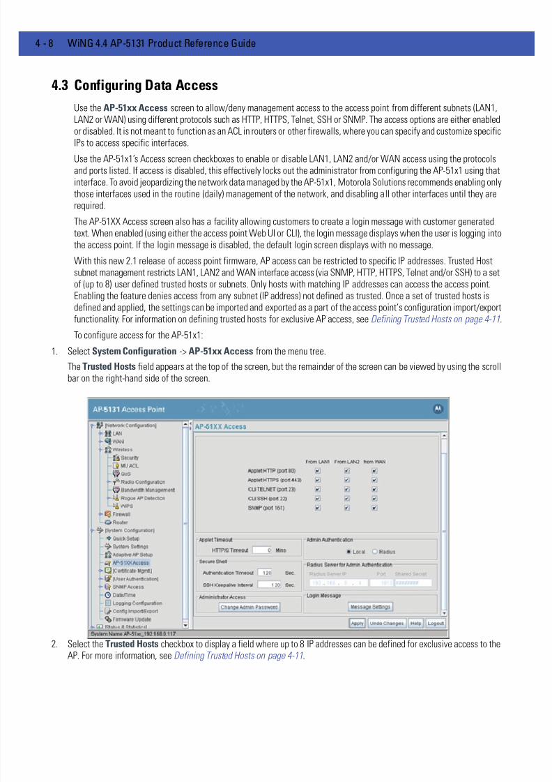
7/18/2019 Motorola AP 5131 Manual
http://slidepdf.com/reader/full/motorola-ap-5131-manual 80/613
4 - 8 WiNG 4.4 AP-5131 Product Reference Guide
4.3 Configuring Data Access
Use the AP-51xx Access screen to allow/deny management access to the access point from different subnets (LAN1,LAN2 or WAN) using different protocols such as HTTP, HTTPS, Telnet, SSH or SNMP. The access options are either enabledor disabled. It is not meant to function as an ACL in routers or other firewalls, where you can specify and customize specificIPs to access specific interfaces.
Use the AP-51x1’s Access screen checkboxes to enable or disable LAN1, LAN2 and/or WAN access using the protocolsand ports listed. If access is disabled, this effectively locks out the administrator from configuring the AP-51x1 using thatinterface. To avoid jeopardizing the network data managed by the AP-51x1, Motorola Solutions recommends enabling onlythose interfaces used in the routine (daily) management of the network, and disabling all other interfaces until they arerequired.
The AP-51XX Access screen also has a facility allowing customers to create a login message with customer generatedtext. When enabled (using either the access point Web UI or CLI), the login message displays when the user is logging intothe access point. If the login message is disabled, the default login screen displays with no message.
With this new 2.1 release of access point firmware, AP access can be restricted to specific IP addresses. Trusted Host
subnet management restricts LAN1, LAN2 and WAN interface access (via SNMP, HTTP, HTTPS, Telnet and/or SSH) to a setof (up to 8) user defined trusted hosts or subnets. Only hosts with matching IP addresses can access the access point.Enabling the feature denies access from any subnet (IP address) not defined as trusted. Once a set of trusted hosts isdefined and applied, the settings can be imported and exported as a part of the access point’s configuration import/exportfunctionality. For information on defining trusted hosts for exclusive AP access, see Defining Trusted Hosts on page 4-11.
To configure access for the AP-51x1:
1. Select System Configuration -> AP-51xx Access from the menu tree.
The Trusted Hosts field appears at the top of the screen, but the remainder of the screen can be viewed by using the scrollbar on the right-hand side of the screen.
2. Select the Trusted Hosts checkbox to display a field where up to 8 IP addresses can be defined for exclusive access to theAP. For more information, see Defining Trusted Hosts on page 4-11.
7/18/2019 Motorola AP 5131 Manual
http://slidepdf.com/reader/full/motorola-ap-5131-manual 81/613
System Configuration 4 - 9
3. Use the AP-51x1 Access field checkboxes to enable/disable the following on the access point’s LAN1, LAN2 or WANinterfaces:
4. Refer to the Applet Timeout field to set an HTTPS timeout interval.
5. Use the Admin Authentication buttons to specify the authentication server connection method.
6. Configure the Secure Shell field to set timeout values to reduce network inactivity.
7. Use the Radius Server if a Radius server has been selected as the authentication server. Enter the required network addressinformation.
Applet HTTP (port 80) Select the LAN1, LAN2 and/or WAN checkboxes to enable access
to the AP-51x1 configuration applet using a Web browser.
Applet HTTPS (port
443)
Select the LAN1, LAN2 and/or WAN checkboxes to enable access
to the AP-51x1 configuration applet using a Secure Sockets Layer
(SSL) for encrypted HTTP sessions.
CLI TELNET (port 23) Select the LAN1, LAN2 and/or WAN checkboxes to enable access
to the AP-51x1 CLI via the TELNET terminal emulation TCP/IP
protocol.
CLI SSH (port 22) Select the LAN1, LAN2 and/or WAN checkboxes to enable access
to the AP-51x1 CLI using the SSH (Secure Shell) protocol.
SNMP (port 161) Select the LAN1, LAN2 and/or WAN checkboxes to enable access
to the AP-51x1 configuration settings from an SNMP-capable
client.
HTTP/S Timeout Disables access to the access point if no data activity is detected
over Applet HTTPS (port 443) after the user defined interval.
Default is 0 Mins.
Local The AP-51x1 verifies the authentication connection.
Radius Designates that a Radius server is used in the authentication
credential verification. If using this option, the connected PC isrequired to have its Radius credentials verified with an external
Radius server. Additionally, the Radius Server’s Active Directory
should have a valid user configured and have a PAP based Remote
Access Policy configured for Radius Admin Authentication to work.
Authentication
Timeout
Defines the maximum time (between 30 - 120 seconds) allowed for
SSH authentication to occur before executing a timeout. The
minimum permissible value is 30 seconds.
SSH Keepalive
Interval
The SSH Keepalive Interval defines a period (in seconds) after
which if no data has been received from a client, SSH sends a
message through the encrypted channel to request a response from
the client. The default is 0, and no messages will be sent to the
client until a non-zero value is set. Defining a Keepalive interval is
important, otherwise programs running on a server may never
notice if the other end of a connection is rebooted.

7/18/2019 Motorola AP 5131 Manual
http://slidepdf.com/reader/full/motorola-ap-5131-manual 82/613
4 - 10 WiNG 4.4 AP-5131 Product Reference Guide
8. Update the Administrator Access field to change the administrative password used to access the configuration settings.
9. Refer to the Login Message field to optionally define a message displayed to the customer as they login into the accesspoint.
Radius Server IP Specify the numerical (non DNS name) IP address of the Remote
Authentication Dial-In User Service (Radius) server. Radius is a
client/server protocol and software enabling remote-access
servers to communicate with a server used to authenticate users
and authorize access to the requested system or service.
Port Specify the port on which the server is listening. The Radius server
typically listens on ports 1812 (default port).
Shared Secret Define a shared secret for authentication on the server. The shared
secret is required to be the same as the shared secret defined on
the Radius server. Use shared secrets to verify Radius messages
(with the exception of the Access-Request message) sent by a
Radius-enabled device configured with the same shared secret.
Apply the qualifications of a well-chosen password to the
generation of a shared secret. Generate a random, case-sensitive
string using letters and numbers. The default is motorola.
Change Admin
Password
Click the Change Admin Password button to display a screen
for updating the AP administrator password. Enter and confirm a
new administrator password as required.
Message Settings Click the Message Settings button to display a screen used to
create a text message. Once displayed, select the Enable LoginMessage checkbox to allow your customized message to be
displayed when the user is logging into the access point. If thecheckbox is not selected (as is the case by default), the user will
encounter the login screen with no additional message.
When the login message function is enabled, the user can enter a
(511 character maximum) message describing any usage caveat
required (such as the authorization disclaimer displayed on the
following page). Thus, the login message can serve an important
function by discouraging unauthorized users from illegally
managing the access point. As your message is entered, the
character usage counter is updated to allow you to visualize how
close you are coming to the maximum allowed number of
characters. Click the Clear button at any time to remove the
contents of the message and begin a new one. Once you have
finished creating your message, click the OK button to return to theAP-51XX access screen.

7/18/2019 Motorola AP 5131 Manual
http://slidepdf.com/reader/full/motorola-ap-5131-manual 83/613
System Configuration 4 - 11
10. Click Apply to save any changes to the AP-51x1 Access screen. Navigating away from the screen without clicking the Applybutton results in all changes to the screen being lost.
11. Click Undo Changes (if necessary) to undo any changes made. Undo Changes reverts the settings displayed on the AP-51x1Access screen to the last saved configuration.
12. Click Logout to securely exit the AP-51x1 Access Point applet. A prompt displays confirming the logout before the applet isclosed.
4.3.1 Defining Trusted Hosts
AP-51xx access can be restricted to up 8 specific IP addresses. Trusted Host management restricts LAN1, LAN2 and WANaccess (via SNMP, HTTP, HTTPS, Telnet and SSH). Only hosts with IP addresses matching those defined within the TrustedHost Access field are able to access the access point. Enabling the feature denies access from any subnet (IP address)not defined as trusted.
To restrict AP access to a set of user defined IP addresses:
1. Select System Configuration -> AP-51xx Access from the menu tree.

7/18/2019 Motorola AP 5131 Manual
http://slidepdf.com/reader/full/motorola-ap-5131-manual 84/613
4 - 12 WiNG 4.4 AP-5131 Product Reference Guide
2. Select the Trusted Hosts checkbox.
The Trusted Host Access field displays. The remaining portion of the Access screen (not related to Trusted Host support)can be accessed using the scroll bar on the right-hand side of the AP-51XX Access screen.
3. Click the Add button and define an IP address in the subsequent pop-up screen.
Individually define up to 8 addresses using the Add function. Each address defined will be granted permission to access pointresources.
4. Select an existing IP address and click the Edit button to modify the address if no longer relevant.
5. If you are near the capacity of 8 allowed IP addresses or an address becomes obsolete, consider selecting an existingaddress and click the Delete button to remove an address.
6. Click Apply to save any changes to the Access screen’s Trusted Host configuration. Navigating away from the screenwithout clicking Apply results in all changes to the screen being lost.
7. Click Undo Changes (if necessary) to undo any changes made. Undo Changes reverts the Trusted Host settings within theAccess screen to the last saved configuration.
8. Click Logout to securely exit the AP-51x1 Access Point applet. A prompt displays confirming the logout before the applet isclosed.
7/18/2019 Motorola AP 5131 Manual
http://slidepdf.com/reader/full/motorola-ap-5131-manual 85/613
System Configuration 4 - 13
4.4 Managing Certificate Authority (CA) Certificates
Certificate management includes the following sections:
• Importing a CA Certificate
• Creating Self Certificates for Accessing the VPN
• Apache Certificate Management
4.4.1 Importing a CA Certificate
A certificate authority (CA) is a network authority that issues and manages security credentials and public keys formessage encryption. The CA signs all digital certificates that it issues with its own private key. The corresponding publickey is contained within the certificate and is called a CA certificate. A browser must contain this CA certificate in itsTrusted Root Library so it can trust certificates “signed” by the CA's private key.
Depending on the public key infrastructure, the digital certificate includes the owner's public key, the certificate expirationdate, the owner's name and other public key owner information.
The AP-51x1 can import and maintain a set of CA certificates to use as an authentication option for Virtual Private Network(VPN) access. To use the certificate for a VPN tunnel, define a tunnel and select the IKE settings to use either RSA or DEScertificates. For additional information on configuring VPN tunnels, see Configuring VPN Tunnels on page 6-32 .
Refer to your network administrator to obtain a CA certificate to import into the AP-51x1.
To import a CA certificate:
1. Select System Configuration -> Certificate Mgmt -> CA Certificates from the menu tree.
CAUTION Loaded and signed CA certificates will be lost when changing theaccess point’s firmware version using either the GUI or CLI. After acertificate has been successfully loaded, export it to a secure locationto ensure its availability after a firmware update.
If restoring the access point’s factory default firmware, you mustexport the certificate file BEFORE restoring the access point’s factorydefault configuration. Import the file back after the updated firmwareis installed. For information on using the access point CLI to importand export the access point’s configuration, seeAP51xx>admin(system.cmgr)> impcert on page 8-160 andAP51xx>admin(system.cmgr)> expcert on page 8-159 .
NOTE Verify the AP-51x1 device time is synchronized with an NTP server beforeimporting a certificate to avoid issues with conflicting date/time stamps.For more information, see Configuring Network Time Protocol (NTP) onpage 4-33 .

7/18/2019 Motorola AP 5131 Manual
http://slidepdf.com/reader/full/motorola-ap-5131-manual 86/613
4 - 14 WiNG 4.4 AP-5131 Product Reference Guide
2. Copy the content of the CA Certificate message (using a text editor such as notepad) and click on Paste from Clipboard.
The content of the certificate displays in the Import a root CA Certificate field.
3. Click the Import root CA Certificate button to import it into the CA Certificate list.
4. Once in the list, select the certificate ID within the View Imported root CA Certificates field to view the certificate issuername, subject, and certificate expiration data.
5. To delete a certificate, select the Id from the drop-down menu and click the Del button.
4.4.2 Creating Self Certificates for Accessing the VPN
The AP-51x1 requires two kinds of certificates for accessing the VPN, CA certificates and self certificates. Self certificatesare certificate requests you create, send to a Certificate Authority (CA) to be signed, then import the signed certificate intothe management system.
To create a self certificate:
1. Select System Configuration -> Certificate Mgmt -> Self Certificates from the AP-51x1 menu tree.
2. Click on the Add button to create the certificate request.
CAUTION Self certificates can only be generated using the access point GUI andCLI interfaces. No functionality exists for creating a self-certificateusing the access point’s SNMP configuration option.
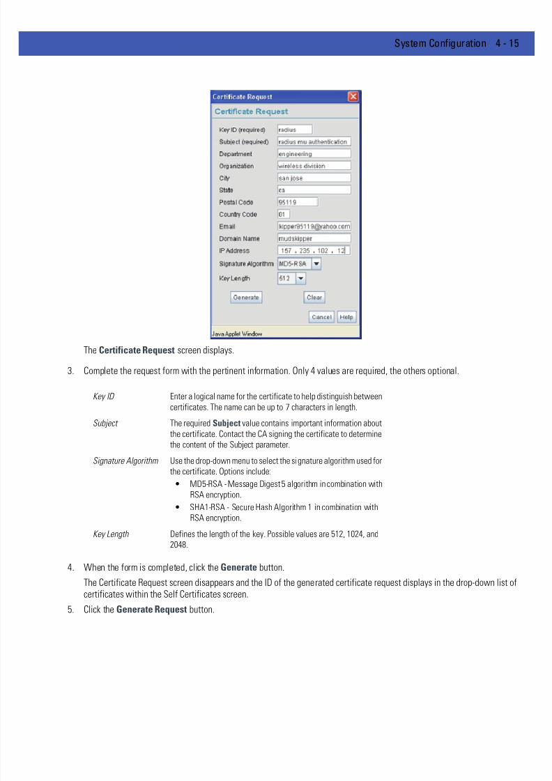
7/18/2019 Motorola AP 5131 Manual
http://slidepdf.com/reader/full/motorola-ap-5131-manual 87/613
System Configuration 4 - 15
The Certificate Request screen displays.
3. Complete the request form with the pertinent information. Only 4 values are required, the others optional.
4. When the form is completed, click the Generate button.
The Certificate Request screen disappears and the ID of the generated certificate request displays in the drop-down list ofcertificates within the Self Certificates screen.
5. Click the Generate Request button.
Key ID Enter a logical name for the certificate to help distinguish between
certificates. The name can be up to 7 characters in length.Subject The required Subject value contains important information about
the certificate. Contact the CA signing the certificate to determine
the content of the Subject parameter.
Signature Algorithm Use the drop-down menu to select the signature algorithm used for
the certificate. Options include:
• MD5-RSA - Message Digest 5 algorithm in combination with
RSA encryption.
• SHA1-RSA - Secure Hash Algorithm 1 in combination with
RSA encryption.
Key Length Defines the length of the key. Possible values are 512, 1024, and
2048.

7/18/2019 Motorola AP 5131 Manual
http://slidepdf.com/reader/full/motorola-ap-5131-manual 88/613
4 - 16 WiNG 4.4 AP-5131 Product Reference Guide
The generated certificate request displays in Self Certificates screen text box.
6. Click the Copy to Clipboard button.
The content of certificate request is copied to the clipboard.
Create an email to your CA, paste the content of the request into the body of the message and send it to the CA.
The CA signs the certificate and will send it back. Once received, copy the content from the email into the clipboard.
7. Click the Paste from clipboard button.
The content of the email displays in the window.
Click the Load Certificate button to import the certificate and make it available for use as a VPN authentication option. Thecertificate ID displays in the Signed list.
8. To use the certificate for a VPN tunnel, first define a tunnel and select the IKE settings to use either RSA or DES certificates.
For additional information on configuring VPN tunnels, see Configuring VPN Tunnels on page 6-32 .
4.4.3 Creating a Certificate for Onboard Radius Authentication
The AP-51x1 can use its on-board Radius Server to generate certificates to authenticate MUs for use with the access point.In addition, a Windows 2000 or 2003 Server is used to sign the certificate before downloading it back to the access point’son-board Radius server and loading the certificate for use with the access point.
Both a CA and Self certificate are required for Onboard Radius Authentication. For information on CA Certificates, see
Importing a CA Certificate on page 4-13 . Ensure the certificate is in a Base 64 Encoded format or risk loading an invalid
certificate.
NOTE If the AP-51x1 is restarted after a certificate request has been generatedbut before the signed certificate is imported, the import will not executeproperly. Do not restart the AP-51x1 during this process.

7/18/2019 Motorola AP 5131 Manual
http://slidepdf.com/reader/full/motorola-ap-5131-manual 89/613
System Configuration 4 - 17
To create a self certificate for on-board Radius authentication:
1. Select System Configuration -> Certificate Mgmt -> Self Certificates from the AP-51x1 menu tree.
2. Click on the Add button to create the certificate request.
The Certificate Request screen displays.
3. Complete the request form with the pertinent information.
CAUTION If using the Radius time-based authentication feature to authenticateaccess point user permissions, ensure the access point’s time issynchronized with the CA server used to generate certificate requests.
CAUTION Self certificates can only be generated using the access point GUI andCLI interfaces. No functionality exists for creating a self-certificateusing the access point’s SNMP configuration option.
Key ID (required) Enter a logical name for the certificate to help distinguish between
certificates. The name can be up to 7 characters in length.
Subject (required) The required Subject value contains important information about
the certificate. Contact the CA signing the certificate to determine
the content of the Subject parameter.
Department Optionally enter a value for your organizations’s department name
if needing to differentiate the certificate from similar certificates
used in other departments within your organization.
Organization Optionally enter the name of your organization for supporting
information for the certificate request.
City Optionally enter the name of the City where the access point (using
the certificate) resides.
State Optionally enter the name of the State where the access point
(using the certificate) resides.
Postal Code Optionally enter the name of the Postal (Zip) Code where the
access point (using the certificate) resides.
Country Code Optionally enter the access point’s Country Code.
Email Enter a organizational email address (avoid using a personal
address if possible) to associate the request with the proper
requesting organization.
Domain Name Ensure the Domain name is the name of the CA Server. This value
must be set correctly to ensure the certificate is properly
generated.
IP Address Enter the IP address of this access point (as you are using the
access point’s onbard Radius server).

7/18/2019 Motorola AP 5131 Manual
http://slidepdf.com/reader/full/motorola-ap-5131-manual 90/613
4 - 18 WiNG 4.4 AP-5131 Product Reference Guide
4. Complete as many of the optional values within the Certificate Request screen as possible.
5. When the form is completed, click the Generate button from within the Certificate Request screen.
The Certificate Request screen disappears and the ID of the generated certificate request displays in the drop-down list ofcertificates within the Self Certificates screen.
6. Click the Generate Request button from within the Self Certificates screen. The certificate content displays within the SelfCertificate screen.
7. Click the Copy to clipboard button. Save the certificate content to a secure location.
8. Connect to the Windows 2000 or 2003 server used to sign the certificate.
9. Select the Request a certificate option. Click Next to continue.
10. Select the Advanced request checkbox from within the Choose Request Type screen and click Next to continue.
11. From within the Advanced Certificate Requests screen, select the Submit a certificate request using a base 64encoded PKCS #10 file or a renewal request using a base64 encoded PKCS file option. Click Next to continue.
12. Paste the content of certificate in the Saved Request field (within the Submit a Saved Request screen).
If you do not have administrative privileges, ensure the Web Server option has been selected from the Certificate Templatedrop-down menu. Click Submit.
13. Select the Base 64 encoded checkbox option from within the Certificate Issued screen and select the Download CA
Certificate link.A File Download screen displays prompting the user to select the download location for the certificate.
14. Click the Save button and save the certificate to a secure location.
15. Load the certificates on the access point.
16. Open the certificate file and copy its contents into the CA Certificates screen by clicking the Paste from Clipboard button.
Signature Algorithm Use the drop-down menu to select the signature algorithm used for
the certificate. Options include:
• MD5-RSA - Message Digest 5 algorithm in combination with
RSA encryption.
• SHA1-RSA - Secure Hash Algorithm 1 in combination withRSA encryption.
Key Length Defines the length of the key. Possible values are 512, 1024, and
2048. Motorola Solutions recommends setting this value to 1024 to
ensure optimum functionality.
NOTE A Warning screen may display at this phase stating key information couldbe lost if you proceed with the certificate request. Click the OK button tocontinue, as the certificate has not been signed yet.
NOTE An administrator must make sure the Web Server option is available as aselectable option for those without administrative privileges.
CAUTION Ensure the CA Certificate is loaded before the Self Certificate, or riskan invalid certificate load.
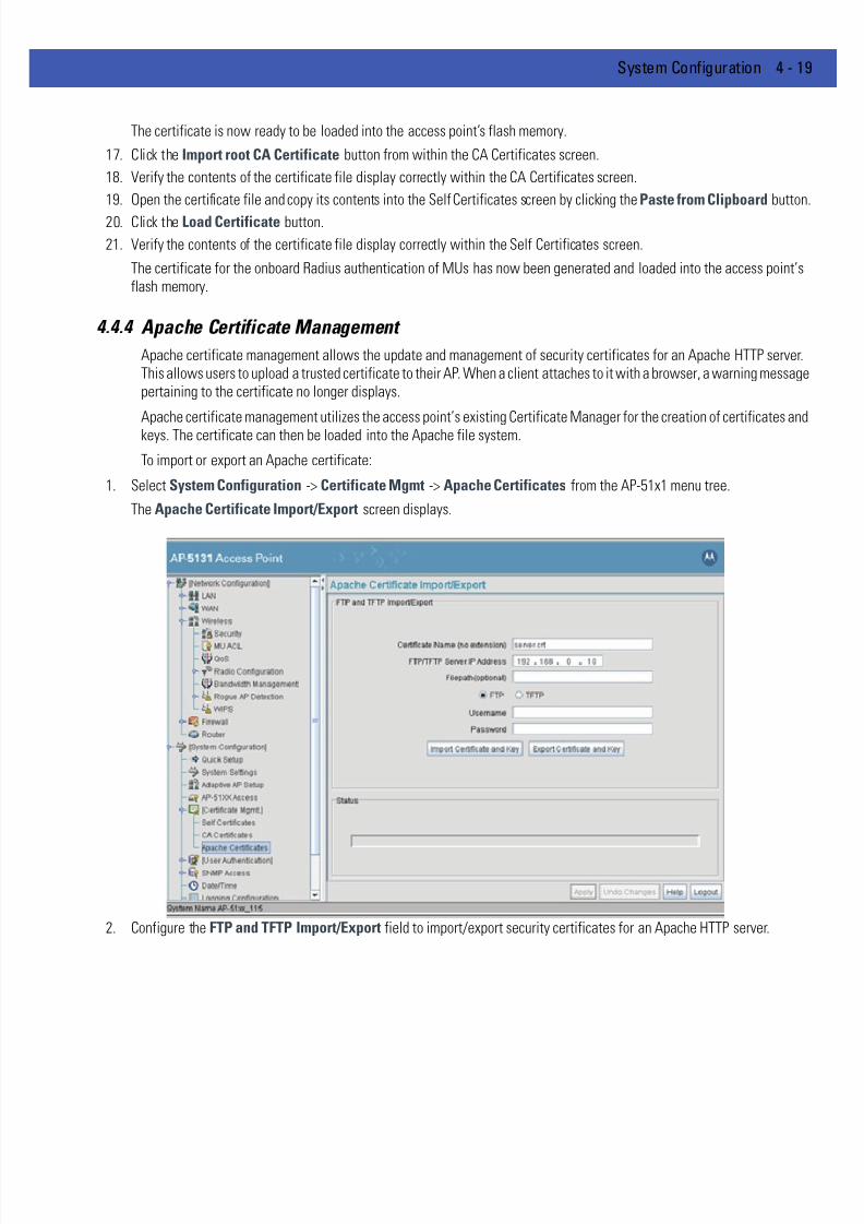
7/18/2019 Motorola AP 5131 Manual
http://slidepdf.com/reader/full/motorola-ap-5131-manual 91/613
System Configuration 4 - 19
The certificate is now ready to be loaded into the access point’s flash memory.
17. Click the Import root CA Certificate button from within the CA Certificates screen.
18. Verify the contents of the certificate file display correctly within the CA Certificates screen.
19. Open the certificate file and copy its contents into the Self Certificates screen by clicking the Paste from Clipboard button
20. Click the Load Certificate button.
21. Verify the contents of the certificate file display correctly within the Self Certificates screen.
The certificate for the onboard Radius authentication of MUs has now been generated and loaded into the access point’sflash memory.
4.4.4 Apache Certificate Management
Apache certificate management allows the update and management of security certificates for an Apache HTTP server.This allows users to upload a trusted certificate to their AP. When a client attaches to it with a browser, a warning messagepertaining to the certificate no longer displays.
Apache certificate management utilizes the access point’s existing Certificate Manager for the creation of certificates andkeys. The certificate can then be loaded into the Apache file system.
To import or export an Apache certificate:
1. Select System Configuration -> Certificate Mgmt -> Apache Certificates from the AP-51x1 menu tree.
The Apache Certificate Import/Export screen displays.
2. Configure the FTP and TFTP Import/Export field to import/export security certificates for an Apache HTTP server.

7/18/2019 Motorola AP 5131 Manual
http://slidepdf.com/reader/full/motorola-ap-5131-manual 92/613
4 - 20 WiNG 4.4 AP-5131 Product Reference Guide
3. Refer to the Status field to review the progress of an import or export operation.
When an import operation is in progress, an “importing certificate and key” message displays. Once completed, anindication of the import or export operation’s success or failure displays.
4. Click Apply to save any changes to the Apache certificate import/export configuration. Navigating away from the screenwithout clicking Apply results in all changes to the screen being lost.
5. Click Undo Changes (if necessary) to undo any changes made. Undo Changes reverts the settings within the screen to thelast saved configuration.
6. Click Logout to securely exit the Access Point applet. A prompt displays confirming the logout before the applet is closed.
Certificate Name (no
extension)
Specify the name of the certificate file to be written to the FTP or
TFTP server. Do not enter the file’s extension.
FTP/TFTP Server IP
Address
Enter the numerical (non DNS name) IP address of the destination
FTP or TFTP server where the security certificate is imported orexported.
Filepath (optional) Defines the optional path name used to import/export the target
security certificate.
FTP Select the FTP radio button if using an FTP server to import or
export the security certificate.
TFTP Select the TFTP radio button if using an FTP server to import or
export the security certificate.
Username Specify a username to be used when logging in to the FTP server.
A username is not required for TFTP server logins.
Password Define a password allowing access to the FTP server for the import
or export operation.
Import Certificate and
Key
Click the Import Certificate and Key button to import the security
certificate from the server with the assigned filename and login
information.
Export Certificate and
Key
Click the Export Certificate and Key button to export the security
certificate from the server with the assigned filename and login
information.

7/18/2019 Motorola AP 5131 Manual
http://slidepdf.com/reader/full/motorola-ap-5131-manual 93/613
System Configuration 4 - 21
4.5 Configuring SNMP Settings
Simple Network Management Protocol (SNMP) facilitates the exchange of management information between networkdevices. SNMP uses Management Information Bases (MIBs) to manage the device configuration and monitor Internetdevices in potentially remote locations. MIB information accessed via SNMP is defined by a set of managed objects calledobject identifiers (OIDs) . An object identifier (OID) is used to uniquely identify each object variable of a MIB. The AP-5131MIB can be used with an AP-5181 model access point (there is no separate MIB for an AP-5181 model access point). Theaccess point Web download package contains the following 2 MIB files:
• Symbol-CC-WS2000-MIB-2.0 (common MIB file)
• Symbol-AP-5131-MIB (AP-5131 specific MIB file)
If using the Symbol-CC-WS2000-MIB-2.0 and/or Symbol-AP-5131-MIB to configure the AP-5131, use the table below tolocate the MIB where the feature can be configured.
NOTE The Symbol-AP-5131-MIB contains the majority of the informationcontained within the Symbol-CC-WS2000-MIB-2.0 file. This feature richinformation has been validated with the Motorola Solutions WS2000 andproven reliable. The remaining portion of the Symbol-AP-5131-MIBcontains supplemental information unique to the access point feature set.
Feature MIB Feature MIB
LAN Configuration Symbol-AP-5131-MIB Subnet Configuration Symbol-CC-WS2000-MIB-2.0
VLAN Configuration Symbol-AP-5131-MIB DHCP Server
Configuration
Symbol-CC-WS2000-MIB-2.0
802.1x Port
Authentication
Symbol-AP-5131-MIB Advanced DHCP
Server configuration
Symbol-CC-WS2000-MIB-2.0
Ethernet Type Filter
Configuration
Symbol-AP-5131-MIB WAN IP Configuration Symbol-CC-WS2000-MIB-2.0
Wireless
Configuration
Symbol-AP-5131-MIB PPP Over Ethernet Symbol-CC-WS2000-MIB-2.0
Security Configuration Symbol-AP-5131-MIB NAT Address Mapping Symbol-CC-WS2000-MIB-2.0
MU ACL Configuration Symbol-AP-5131-MIB VPN Tunnel
Configuration
Symbol-CC-WS2000-MIB-2.0
QOS Configuration Symbol-AP-5131-MIB VPN Tunnel status Symbol-CC-WS2000-MIB-2.0
Radio Configuration Symbol-AP-5131-MIB Content Filtering Symbol-CC-WS2000-MIB-2.0
Bandwidth
Management
Symbol-AP-5131-MIB Rogue AP Detection Symbol-CC-WS2000-MIB-2.0
SNMP Trap Selection Symbol-AP-5131-MIB Firewall Configuration Symbol-CC-WS2000-MIB-2.0
SNMP RF Trap
Thresholds
Symbol-AP-5131-MIB LAN to WAN Access Symbol-CC-WS2000-MIB-2.0
Config Import/Export Symbol-AP-5131-MIB Advanced LAN Access Symbol-CC-WS2000-MIB-2.0
MU Authentication
Stats
Symbol-AP-5131-MIB Router Configuration Symbol-CC-WS2000-MIB-2.0
WNMP Ping
Configuration
Symbol-AP-5131-MIB System Settings Symbol-CC-WS2000-MIB-2.0
7/18/2019 Motorola AP 5131 Manual
http://slidepdf.com/reader/full/motorola-ap-5131-manual 94/613
4 - 22 WiNG 4.4 AP-5131 Product Reference Guide
SNMP allows a network administrator to manage network performance, find and solve network problems, and plan fornetwork growth. The AP-51x1 supports SNMP management functions for gathering information from its networkcomponents, communicating that information to specified users and configuring the access point. All the fields availablewithin the access point are also configurable within the MIB.
The AP-51x1 SNMP agent functions as a command responder and is a multilingual agent responding to SNMPv1, v2c andv3 managers (command generators). The factory default configuration maintains SNMPv1/2c support of the communitynames, hence providing backward compatibility.
SNMP v1/v2c community definitions and SNMP v3 user definitions work independently, and both use the Access ControlList (ACL) of the SNMP Access Control sub-screen.
Use the SNMP Access screen to define SNMP v1/v2c community definitions and SNMP v3 user definitions. SNMPversion 1 (v1) provides a strong network management system, but its security is relatively weak. The improvements inSNMP version 2c (v2c) do not include the attempted security enhancements of other version-2 protocols. Instead, SNMPv2c defaults to SNMP-standard community strings for read-only and read/write access. SNMP version 3 (v3) furtherenhances protocol features, providing much improved security. SNMP v3 encrypts transmissions and providesauthentication for users generating requests.
To configure SNMP v1/v2c community definitions and SNMP v3 user definitions for the AP-51x1:
1. Select System Configuration - > SNMP Access from the AP-51x1 menu tree.
Known AP Stats Symbol-AP-5131-MIB AP 5131 Access Symbol-CC-WS2000-MIB-2.0
Flash LEDs Symbol-AP-5131-MIB Certificate Mgt Symbol-CC-WS2000-MIB-2.0
Automatic Update Symbol-AP-5131-MIB SNMP Access
Configuration
Symbol-CC-WS2000-MIB-2.0
SNMP Trap
Configuration
Symbol-CC-WS2000-MIB-2.0
NTP Server
Configuration
Symbol-CC-WS2000-MIB-2.0
Logging Configuration Symbol-CC-WS2000-MIB-2.0
Firmware Update Symbol-CC-WS2000-MIB-2.0
Wireless Stats Symbol-CC-WS2000-MIB-2.0
Radio Stats Symbol-CC-WS2000-MIB-2.0
MU Stats Symbol-CC-WS2000-MIB-2.0
Automatic Update Symbol-CC-WS2000-MIB-2.0
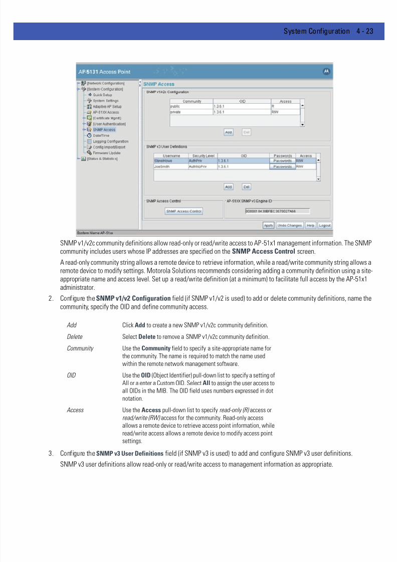
7/18/2019 Motorola AP 5131 Manual
http://slidepdf.com/reader/full/motorola-ap-5131-manual 95/613
System Configuration 4 - 23
SNMP v1/v2c community definitions allow read-only or read/write access to AP-51x1 management information. The SNMPcommunity includes users whose IP addresses are specified on the SNMP Access Control screen.
A read-only community string allows a remote device to retrieve information, while a read/write community string allows aremote device to modify settings. Motorola Solutions recommends considering adding a community definition using a siteappropriate name and access level. Set up a read/write definition (at a minimum) to facilitate full access by the AP-51x1administrator.
2. Configure the SNMP v1/v2 Configuration field (if SNMP v1/v2 is used) to add or delete community definitions, name thecommunity, specify the OID and define community access.
3. Configure the SNMP v3 User Definitions field (if SNMP v3 is used) to add and configure SNMP v3 user definitions.
SNMP v3 user definitions allow read-only or read/write access to management information as appropriate.
Add Click Add to create a new SNMP v1/v2c community definition.
Delete Select Delete to remove a SNMP v1/v2c community definition.
Community Use the Community field to specify a site-appropriate name for
the community. The name is required to match the name used
within the remote network management software.
OID Use the OID (Object Identifier) pull-down list to specify a setting of
All or a enter a Custom OID. Select All to assign the user access to
all OIDs in the MIB. The OID field uses numbers expressed in dotnotation.
Access Use the Access pull-down list to specify read-only (R) access or
read/write (RW) access for the community. Read-only access
allows a remote device to retrieve access point information, while
read/write access allows a remote device to modify access point
settings.
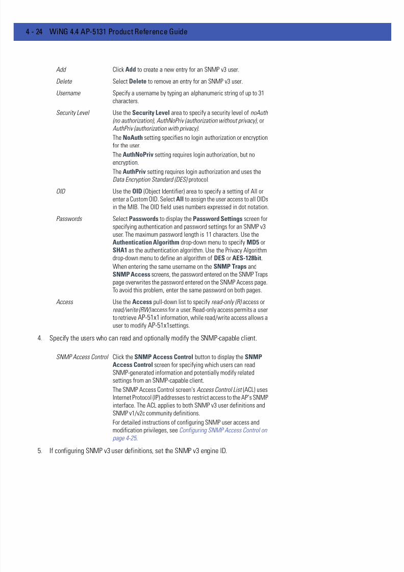
7/18/2019 Motorola AP 5131 Manual
http://slidepdf.com/reader/full/motorola-ap-5131-manual 96/613
4 - 24 WiNG 4.4 AP-5131 Product Reference Guide
4. Specify the users who can read and optionally modify the SNMP-capable client.
5. If configuring SNMP v3 user definitions, set the SNMP v3 engine ID.
Add Click Add to create a new entry for an SNMP v3 user.
Delete Select Delete to remove an entry for an SNMP v3 user.
Username Specify a username by typing an alphanumeric string of up to 31
characters.
Security Level Use the Security Level area to specify a security level of noAuth
(no authorization) , AuthNoPriv (authorization without privacy) , or
AuthPriv (authorization with privacy) .
The NoAuth setting specifies no login authorization or encryption
for the user.
The AuthNoPriv setting requires login authorization, but no
encryption.
The AuthPriv setting requires login authorization and uses the
Data Encryption Standard (DES) protocol.
OID Use the OID (Object Identifier) area to specify a setting of All or
enter a Custom OID. Select All to assign the user access to all OIDsin the MIB. The OID field uses numbers expressed in dot notation.
Passwords Select Passwords to display the Password Settings screen for
specifying authentication and password settings for an SNMP v3
user. The maximum password length is 11 characters. Use the
Authentication Algorithm drop-down menu to specify MD5 or
SHA1 as the authentication algorithm. Use the Privacy Algorithm
drop-down menu to define an algorithm of DES or AES-128bit.
When entering the same username on the SNMP Traps and
SNMP Access screens, the password entered on the SNMP Traps
page overwrites the password entered on the SNMP Access page.
To avoid this problem, enter the same password on both pages.
Access Use the Access pull-down list to specify read-only (R) access orread/write (RW) access for a user. Read-only access permits a user
to retrieve AP-51x1 information, while read/write access allows a
user to modify AP-51x1settings.
SNMP Access Control Click the SNMP Access Control button to display the SNMPAccess Control screen for specifying which users can read
SNMP-generated information and potentially modify related
settings from an SNMP-capable client.
The SNMP Access Control screen's Access Control List (ACL) uses
Internet Protocol (IP) addresses to restrict access to the AP’s SNMPinterface. The ACL applies to both SNMP v3 user definitions and
SNMP v1/v2c community definitions.
For detailed instructions of configuring SNMP user access and
modification privileges, see Configuring SNMP Access Control on
page 4-25 .

7/18/2019 Motorola AP 5131 Manual
http://slidepdf.com/reader/full/motorola-ap-5131-manual 97/613
System Configuration 4 - 25
6. Click Apply to save any changes to the SNMP Access screen. Navigating away from the screen without clicking the Applybutton results in all changes to the screen being lost.
7. Click Undo Changes (if necessary) to undo any changes made. Undo Changes reverts the settings displayed on the SNMPAccess screen to the last saved configuration.
8. Click Logout to securely exit the AP-51x1 Access Point applet. A prompt displays confirming the logout before the applet isclosed.
For additional SNMP configuration information, see:
• Configuring SNMP Access Control
• Enabling SNMP Traps
• Configuring Specific SNMP Traps • Configuring SNMP RF Trap Thresholds
4.5.1 Configuring SNMP Access Control
Use the SNMP Access Control screen (as launched from the SNMP Access screen) to specify which users can readSNMP generated information and, if capable, modify related settings from an SNMP-capable client.
Use the SNMP Access Control screen's Access Control List (ACL) to limit, by Internet Protocol (IP) address, who can accessthe AP-51x1 SNMP interface.
To configure SNMP user access control for the AP-51x1:
1. Select System Configuration - > SNMP Access from the AP-51x1 menu tree. Click on the SNMP Access Control buttonfrom within the SNMP Access screen.
AP-51xx SNMP v3
Engine ID
The AP-51x1 SNMP v3 Engine ID field lists the unique SNMP v3
Engine ID for the AP-51x1. This ID is used in SNMP v3 as the source
for a trap, response or report. It is also used as the destination ID
when sending get, getnext, getbulk , set or inform commands.
NOTE The ACL applies to both SNMP v3 user definitions and SNMP v1/v2ccommunity definitions on the AP-51x1 SNMP Access screen.
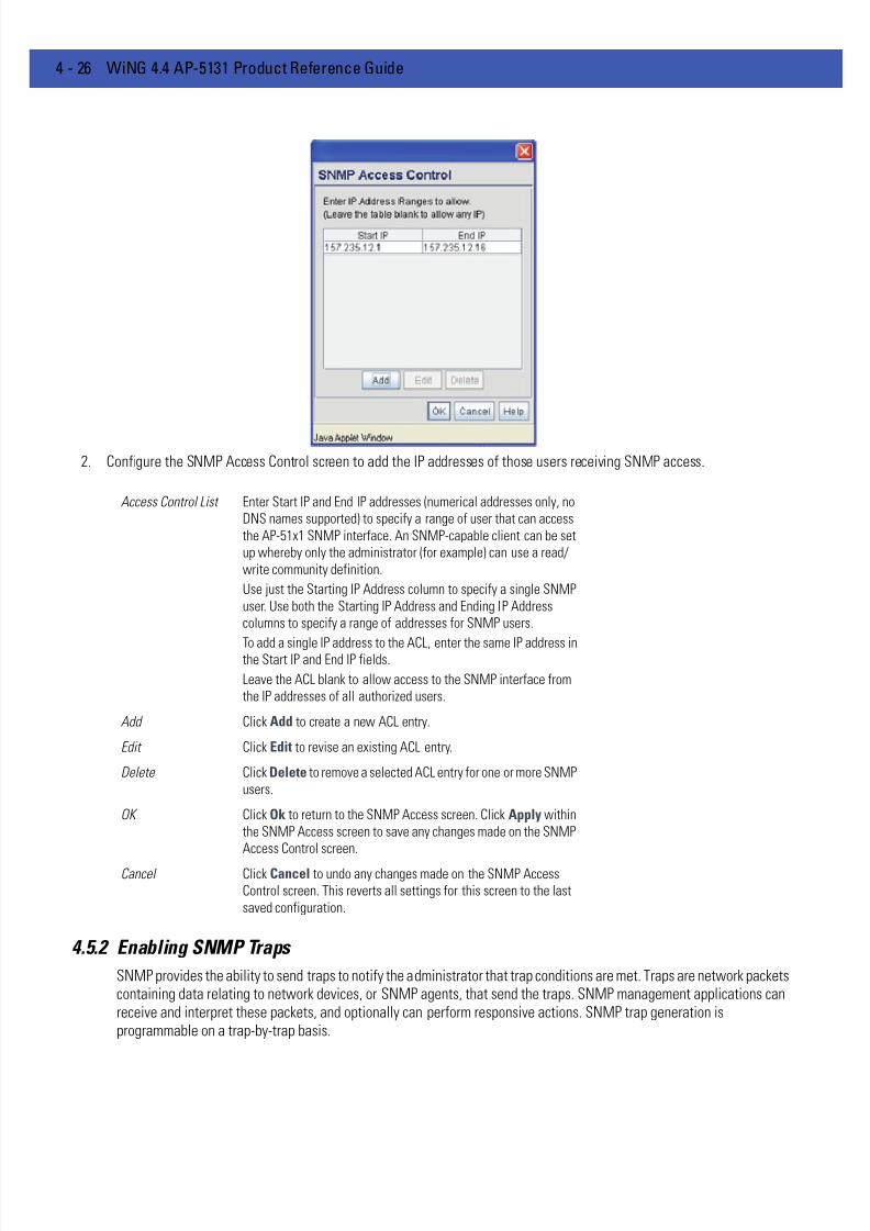
7/18/2019 Motorola AP 5131 Manual
http://slidepdf.com/reader/full/motorola-ap-5131-manual 98/613
4 - 26 WiNG 4.4 AP-5131 Product Reference Guide
2. Configure the SNMP Access Control screen to add the IP addresses of those users receiving SNMP access.
4.5.2 Enabling SNMP Traps
SNMP provides the ability to send traps to notify the administrator that trap conditions are met. Traps are network packetscontaining data relating to network devices, or SNMP agents, that send the traps. SNMP management applications canreceive and interpret these packets, and optionally can perform responsive actions. SNMP trap generation isprogrammable on a trap-by-trap basis.
Access Control List Enter Start IP and End IP addresses (numerical addresses only, no
DNS names supported) to specify a range of user that can access
the AP-51x1 SNMP interface. An SNMP-capable client can be set
up whereby only the administrator (for example) can use a read/
write community definition.
Use just the Starting IP Address column to specify a single SNMP
user. Use both the Starting IP Address and Ending IP Address
columns to specify a range of addresses for SNMP users.
To add a single IP address to the ACL, enter the same IP address inthe Start IP and End IP fields.
Leave the ACL blank to allow access to the SNMP interface from
the IP addresses of all authorized users.
Add Click Add to create a new ACL entry.
Edit Click Edit to revise an existing ACL entry.
Delete Click Delete to remove a selected ACL entry for one or more SNMP
users.
OK Click Ok to return to the SNMP Access screen. Click Apply within
the SNMP Access screen to save any changes made on the SNMP
Access Control screen.
Cancel Click Cancel to undo any changes made on the SNMP Access
Control screen. This reverts all settings for this screen to the last
saved configuration.

7/18/2019 Motorola AP 5131 Manual
http://slidepdf.com/reader/full/motorola-ap-5131-manual 99/613
System Configuration 4 - 27
Use the SNMP Traps Configuration screen to enable traps and to configure appropriate settings for reporting thisinformation. Trap configuration depends on the network machine that receives the generated traps. SNMP v1/v2c and v3trap configurations function independently. In a mixed SNMP environment, generated traps can be sent usingconfigurations for both SNMP v1/v2c and v3.
To configure SNMP traps on the AP-51x1:1. Select System Configuration - > SNMP Access - > SNMP Trap Configuration from the AP-51x1 menu tree.
2. Configure the SNMP v1/v2c Trap Configuration field (if SNMP v1/v2c Traps are used) to modify the following:
3. Configure the SNMP v3 Trap Configuration field (if SNMP v3 Traps are used) to modify the following:
Add Click Add to create a new SNMP v1/v2c Trap Configuration entry.
Delete Click Delete to remove a selected SNMP v1/v2c Trap
Configuration entry.
Destination IP Specify a numerical (non DNS name) destination IP address for
receiving the traps sent by the AP-51x1 SNMP agent.
Port Specify a destination User Datagram Protocol (UDP) port for
receiving traps. The default is 162.
Community Enter a community name specific to the SNMP-capable client that
receives the traps.
SNMP Version Use the SNMP Version drop-down menu to specify v1 or v2.
Some SNMP clients support only SNMP v1 traps, while others
support SNMP v2 traps and possibly both, verify the correct traps
are in use with clients that support them.
Add Click Add to create a new SNMP v3 Trap Configuration entry.
Delete Select Delete to remove an entry for an SNMP v3 user.
7/18/2019 Motorola AP 5131 Manual
http://slidepdf.com/reader/full/motorola-ap-5131-manual 100/613
4 - 28 WiNG 4.4 AP-5131 Product Reference Guide
4. Click Apply to save any changes to the SNMP Trap Configuration screen. Navigating away from the screen without clickingthe Apply button results in all changes being lost.
5. Click Undo Changes (if necessary) to undo any changes made. Undo Changes reverts the settings displayed on SNMP TrapConfiguration screen to the last saved configuration.
6. Click Logout to securely exit the AP-51x1 Access Point applet. A prompt displays confirming the logout before the applet isclosed.
4.5.3 Configuring Specific SNMP Traps
Use the SNMP Traps screen to enable specific traps on the AP-51x1. Motorola Solutions recommends defining traps tocapture unauthorized devices operating within the AP-51x1 coverage area. Trap configuration depends on the networkmachine that receives the generated traps. SNMP v1/v2c and v3 trap configurations function independently. In a mixedSNMP environment, traps can be sent using configurations for both SNMP v1/v2c and v3. To configure specific SNMP trapson the AP-51x1:
1. Select System Configuration - > SNMP Access - > SNMP Traps from the menu tree.
Destination IP Specify a numerical (non DNS name) destination IP address for
receiving the traps sent by the AP-51x1 SNMP agent.
Port Specify a destination User Datagram Protocol (UDP) port for
receiving traps.
Username Enter a username specific to the SNMP-capable client receivingthe traps.
Security Level Use the Security Level drop-down menu to specify a security
level of noAuth (no authorization), AuthNoPriv (authorization
without privacy), or AuthPriv (authorization with privacy).
The “NoAuth” setting specifies no login authorization or encryption
for the user. The “AuthNoPriv” setting requires login authorization,
but no encryption. The “AuthPriv” setting requires login
authorization and uses the Data Encryption Standard (DES) .
Passwords Select Passwords to display the Password Settings screen for
specifying authentication and password settings for an SNMP v3
user. The maximum password length is 11 characters. Use theAuthentication Algorithm drop-down menu to specify MD5 or
SHA1 as the authentication algorithm. Use the Privacy Algorithm
drop-down menu to define an algorithm of DES or AES-128bit.
If entering the same username on the SNMP Traps and SNMP
Access screens, the password entered on the SNMP Traps page
overwrites the password entered on the SNMP Access page. To
avoid this problem, enter the same password on both pages.

7/18/2019 Motorola AP 5131 Manual
http://slidepdf.com/reader/full/motorola-ap-5131-manual 101/613
System Configuration 4 - 29
2. Configure the MU Traps field to generate traps for MU associations, MU association denials and MU authenticationdenials. When a trap is enabled, a trap is sent every 10 seconds until the condition no longer exists.
3. Configure the SNMP Traps field to generate traps when SNMP capable MUs are denied authentication privileges or aresubject of an ACL violation. When a trap is enabled, a trap is sent every 5 seconds until the condition no longer exists.
MU associated Generates a trap when an MU becomes associated with one of the
AP-51x1’s WLANs.
MU unassociated Generates a trap when an MU becomes unassociated with (or gets
dropped from) one of the AP-51x1’s WLANs.
MU denied
association
Generates a trap when an MU is denied association to a AP-51x1
WLAN. Can be caused when the maximum number of MUs for a
WLAN is exceeded or when an MU violates the AP-51x1’s Access
Control List (ACL).
MU denied
authentication
Generates a trap when an MU is denied authentication on one of
the AP’s WLANs. Can be caused by the MU being set for the wrong
authentication type for the WLAN or by an incorrect key or
password.
SNMP authentication
failures
Generates a trap when an SNMP-capable client is denied access
to the AP-51x1’s SNMP management functions or data. This can
result from an incorrect login, or missing/incorrect user credentials.
SNMP ACL violation Generates a trap when an SNMP client cannot access SNMP
management functions or data due to an Access Control List (ACL)
violation. This can result from a missing/incorrect IP address
entered within the SNMP Access Control screen.
7/18/2019 Motorola AP 5131 Manual
http://slidepdf.com/reader/full/motorola-ap-5131-manual 102/613
4 - 30 WiNG 4.4 AP-5131 Product Reference Guide
4. Configure the Network Traps field to generate traps when the AP-51x1’s link status changes or when the AP’s firewalldetects a DOS attack.
5. Configure the System Traps field to generate traps when the AP-51x1 re-initializes during transmission, saves its
configuration file. When a trap is enabled, a trap is sent every 5 seconds until the condition no longer exists.
6. Refer to the Set All Traps field to use a single location to either enable or disable each trap listed within the SNMP Traps
screen.
7. Click Apply to save any changes to the SNMP Traps screen. Navigating away from the screen without clicking the Applybutton results in all changes to the screen being lost.
Physical port status
change
Generates a trap whenever the status changes on the AP-51x1. The
physical port status changes when a link is lost between the AP-
51x1 and a connected device.
DynDNS Update Generates a trap whenever domain name information is updated as
a result of the IP address associated with that domain being
modified.
Denial of service
(DOS) attempts
Generates a trap whenever a Denial of Service (DOS) attack is
detected by the AP-51x1 firewall. A new trap is sent at the
specified interval until the attack has stopped.
Send trap every Defines the interval in seconds the AP-51x1 uses to generate a trap
until the Denial of Service attack is stopped. Default is 10 seconds.
System Cold Start Generates a trap when the AP-51x1 re-initializes while
transmitting, possibly altering the SNMP agent's configuration or
protocol entity implementation.
Configuration
Changes
Generates a trap whenever changes to the AP-51x1’s configuration
file are saved.
Rogue AP Detection Generates a trap if a Rogue AP is detected by the AP-51x1.
AP Radar Detection Generates a trap if an AP is detected using a form of radar
detection.
WPA CounterMeasure Generates a trap if an attack is detected against the WPA KeyExchange Mechanism.
MU Hotspot Status Generates a trap when a change to the status of MU hotspot
member is detected.
VLAN Generates a trap when a change to a VLAN state is detected.
LAN Monitor Generates a trap when a change to the LAN monitoring state is
detected.
Health Check Trap Generates a trap when access to a configured resource such as a
RADIUS server or a web portal is lost.
Enable All Select this button to enable each trap defined within the SNMP
Traps screen. Once the changes are applied, each event listed will
generate a trap upon its occurrence.
Disable All Select this button to disable each trap defined within the SNMP
Traps screen. Once the changes are applied, none of the events
listed will generate a trap upon their occurrence.

7/18/2019 Motorola AP 5131 Manual
http://slidepdf.com/reader/full/motorola-ap-5131-manual 103/613
System Configuration 4 - 31
8. Click Undo Changes (if necessary) to undo any changes made. Undo Changes reverts the settings displayed on SNMP Trapsscreen to the last saved configuration.
9. Click Logout to securely exit the AP-51x1 Access Point applet. A prompt displays confirming the logout before the applet isclosed.
4.5.4 Configuring SNMP RF Trap Thresholds
Use the SNMP RF Trap Threshold screen as a means to track RF activity and the AP-51x1’s radio and associated MUperformance. SNMP RF Traps are sent when RF traffic exceeds defined limits set in the RF Trap Thresholds field of theSNMP RF Traps screen. Thresholds are displayed for the AP-51x1, WLAN, selected radio and the associated MU.
To configure specific SNMP RF Traps on the AP-51x1:
1. Select System Configuration - > SNMP Access - > SNMP RF Trap Thresholds from the menu tree.
2. Configure the RF Trap Thresholds field to define device threshold values for SNMP traps.
NOTE Average Bit Speed,% of Non-Unicast, Average Signal, Average Retries,%Dropped and % Undecryptable are not access point statistics.
Pkts/s Enter a maximum threshold for the total throughput in Pps (Packets
per second).
Throughput Set a maximum threshold for the total throughput in Mbps
(Megabits per second).
Average Bit Speed Enter a minimum threshold for the average bit speed in Mbps
(Megabits per second).
Average Signal Enter a minimum threshold for the average signal strength in dBm
for each device.

7/18/2019 Motorola AP 5131 Manual
http://slidepdf.com/reader/full/motorola-ap-5131-manual 104/613
4 - 32 WiNG 4.4 AP-5131 Product Reference Guide
3. Configure the Minimum Packets field to define a minimum packet throughput value for trap generation.
4. Click Apply to save any changes to the SNMP RF Traps screen. Navigating away from the screen without clicking the Applybutton results in all changes to the screen being lost.
5. Click Undo Changes (if necessary) to undo any changes made. Undo Changes reverts the settings displayed on SNMP RFTraps screen to the last saved configuration.
6. Click Logout to securely exit the AP-51x1 Access Point applet. A prompt displays confirming the logout before the applet isclosed.
Average Retries Set a maximum threshold for the average number of retries for
each device.
% Dropped Enter a maximum threshold for the total percentage of packets
dropped for each device. Dropped packets can be caused by poor
RF signal or interference on the channel.% Undecryptable Define a maximum threshold for the total percentage of packets
undecryptable for each device. Undecryptable packets can be the
result of corrupt packets, bad CRC checks or incomplete packets.
Associated MUs Set a maximum threshold for the total number of MUs associated
with each device.
Minimum number of
packets required for a
trap to fire
Enter the minimum number of packets that must pass through the
device before an SNMP rate trap is sent. Motorola Solutions
recommends using the default setting of 1000 as a minimum
setting for the field.

7/18/2019 Motorola AP 5131 Manual
http://slidepdf.com/reader/full/motorola-ap-5131-manual 105/613
System Configuration 4 - 33
4.6 Configuring Network Time Protocol (NTP)
Network Time Protocol (NTP) manages time and/or network clock synchronization in the AP-51x1-managed networkenvironment. NTP is a client/server implementation. The AP-51x1 (an NTP client) periodically synchronizes its clock witha master clock (an NTP server). For example, the AP-51x1 resets its clock to 07:04:59 upon reading a time of 07:04:59 fromits designated NTP server.
Time synchronization is recommended for the access point’s network operations. For sites using Kerberos authentication,time synchronization is required. Use the Date and Time Settings screen to enable NTP and specify the IP addresses andports of available NTP servers.
To manage clock synchronization on the AP-51x1:
1. Select System Configuration - > Date/Time from the AP-51x1 menu tree.
2. From within the Current Time field, click the Refresh button to update the time since the screen was displayed by the user
The Current Time field displays the current time based on the AP-51x1 system clock. If NTP is disabled or if there are noservers available, the system time displays the AP-51x1 uptime starting at 1970-01-01 00:00:00, with the time and dateadvancing.
3. Select the Set Date/Time button to display the Manual Date/Time Setting screen.
NOTE The current time is not set accurately when initially connecting to the AP-51x1. Until a server is defined to provide the AP-51x1 the correct time, orthe correct time is manually set, the AP-51x1 displays 1970-01-0100:00:00 as the default time.
NOTE If using the Radius time-based authentication feature to authenticate
access point user permissions, ensure UTC has been selected from theDate and Time Settings screen’s Time Zone field. If UTC is not selected,time based authentication will not work properly. For information onconfiguring Radius time-based authentication, seeDefining User Access Permissions by Group on page 6-62 .

7/18/2019 Motorola AP 5131 Manual
http://slidepdf.com/reader/full/motorola-ap-5131-manual 106/613
4 - 34 WiNG 4.4 AP-5131 Product Reference Guide
This screen enables the user to manually enter the access point’s system time using aYear-Month-Day HH:MM:SS format.
This option is disabled when the Enable NTP checkbox has been selected, and therefore should be viewed as a secondmeans to define the access point system time.
4. If using the Manual Date/Time Setting screen to define the access point’s system time, refer to theTime Zone field to selectthe time used to use as complimentary information to the information entered within the Manual Date/Time Setting screen.
5. If using an NTP server to supply system time to the access point, configure the NTP Server Configuration field to definethe server network address information required to acquire the AP-51x1 network time.
6. Click Apply to save any changes to the Date and time Settings screen. Navigating away from the screen without clickingthe Apply button results in all changes to the screen being lost.
7. Click Undo Changes (if necessary) to undo any changes made. Undo Changes reverts the settings displayed on Date and
Time Settings screen to the last saved configuration.8. Click Logout to securely exit the AP-51x1 Access Point applet. A prompt displays confirming the logout before the applet is
closed.
CAUTION If using the Radius time-based authentication feature to authenticateaccess point user permissions, ensure UTC has been selected fromthe Time Zone field. If UTC is not selected, time based authenticationwill not work properly. For information on configuring Radiustime-based authentication, see Defining User Access Permissions byGroup on page 6-62 .
Enable NTP on AP- 51x1
Select the Enable NTP on AP-51x1 checkbox to allow aconnection between the AP-51x1 and one or more specified NTP
servers. A preferred, first alternate and second alternate NTP
server cannot be defined unless this checkbox is selected.
Disable this option (uncheck the checkbox) if Kerberos is not in use
and time synchronization is not necessary.
Preferred Time Server Specify the numerical (non DNS name) IP address and port of the
primary NTP server. The default port is 123.
First Alternate Time
Server
Optionally, specify the numerical (non DNS name) IP address and
port of an alternative NTP server to use for time synchronization if
the primary NTP server goes down.
Second AlternateTime Server
Optionally, specify the numerical (non DNS name) and port of yetanother NTP server for the greatest assurance of uninterrupted
time synchronization.
Synchronization
Interval
Define an interval in minutes the AP-51x1 uses to synchronize its
system time with the NTP server. A synchronization interval value
from 15 minutes to 65535 minutes can be specified. For
implementations using Kerberos, a synchronization interval of 15
minutes (default interval) or sooner is recommended.

7/18/2019 Motorola AP 5131 Manual
http://slidepdf.com/reader/full/motorola-ap-5131-manual 107/613
System Configuration 4 - 35
4.7 Configuring LLDP Settings
Link Layer Discovery Protocol (LLDP) is a Layer 2 protocol (IEEE standard 802.1AB) used to determine the capabilities ofdevices such as repeaters, bridges, access points, routers and wireless clients. LLDP enables devices to advertise theircapabilities and media-specific configurations. LLDP provides a method of discovering and representing the physicalnetwork connections of a given network management domain. The LLDP neighbor discovery protocol allows you todiscover and maintain accurate network topologies in a multi-vendor environment.
The information is in a Type Length Value (TLV) format for each data item. TLV information is transmitted in a LLDP protocoldata unit (LLDPDU), enclosed in an Ethernet frame and sent to a destination MAC address. Certain TLVs are mandatory,and always sent once LLDP is enabled, while other TLVs are optionally configured. LLDP defines a set of commonadvertisement messages, a protocol for transmitting the advertisements and a method for storing information in receivedadvertisements. A switch can receive and record the TLVs, but not transmit them. The information distributed using LLDPis stored by its recipients in a standard MIB, making it possible for the information to be accessed by a NMS using amanagement protocol such as SNMP.
LLDP transmits periodic advertisements containing device information and media-specific configuration information toneighbors attached to the same network. LLDP agents cannot solicit information from other agents by using LLDP.
To configure LLDP support:
1. Select System Configuration - > LLDP from the menu tree.
2. Select the Enable LLDP radio button to enable or disable the transmission of LLDP advertisements. LLDP is enabled bydefault.
3. Set a Refresh Interval (in seconds 5-32768) to define the LLDP refresh-interval/transmit-interval. The Refresh Interval isthe interval LLDP frames are transmitted on behalf of the LLDP agent. The default is 30 seconds.
4. Set a Holdtime Multiplier (2-10) to define the holdtime multiplier. This parameter is a multiplier on the Refresh Intervalthat determines the actual TTL value used in an LLDPDU.The default setting is 4.
5. Click Apply to save any changes to the LLDP screen. Navigating away from the screen without clicking the Apply buttonresults in all changes to the screen being lost.

7/18/2019 Motorola AP 5131 Manual
http://slidepdf.com/reader/full/motorola-ap-5131-manual 108/613
4 - 36 WiNG 4.4 AP-5131 Product Reference Guide
6. Click Undo Changes (if necessary) to undo any changes made. Undo Changes reverts the settings displayed on LLDP screento the last saved configuration.

7/18/2019 Motorola AP 5131 Manual
http://slidepdf.com/reader/full/motorola-ap-5131-manual 109/613
System Configuration 4 - 37
4.8 Logging Configuration
The AP-51x1 provides the capability for periodically logging system events that prove useful in assessing the throughputand performance of the AP-51x1 or troubleshooting problems on the AP-51x1 managed Local Area Network (LAN). Use theLogging Configuration screen to set the desired logging level (standard syslog levels) and view or save the current AP51x1 system log.
To configure event logging for the AP-51x1:
1. Select System Configuration - > Logging Configuration from the AP-51x1 menu tree.
2. Configure the Log Options field to save event logs, set the log level and optionally port the AP-51x1’s log to an externalserver.
7/18/2019 Motorola AP 5131 Manual
http://slidepdf.com/reader/full/motorola-ap-5131-manual 110/613
4 - 38 WiNG 4.4 AP-5131 Product Reference Guide
3. Click Apply to save any changes to the Logging Configuration screen. Navigating away from the screen without clicking theApply button results in all changes to the screen being lost.
4. Click Undo Changes (if necessary) to undo any changes made. Undo Changes reverts the settings displayed on the LoggingConfiguration screen to the last saved configuration.
5. Click Logout to securely exit the AP-51x1 Access Point applet. A prompt displays confirming the logout before the applet isclosed.
View Log Click View to save a log of events retained on the AP-51x1. The
system displays a prompt requesting the administrator password
before saving the log. After the password has been entered, click
Get File to display a dialogue with buttons to Open or Save the
log.txt file. Click Save and specify a location to save the log file.Use the WordPad application to view the saved log.txt file on a
Microsoft Windows based computer. Do not view the log file using
Notepad, as the Notepad application does not properly display the
formatting of the AP-51x1 log file. Log entries are not saved in the
AP-51x1. While the AP is in operation, log data temporarily resides
in memory. AP memory is completely cleared each time the AP
reboots.
Logging Level Use the Logging Level drop-down menu to select the desired log
level for tracking system events. Eight logging levels, (0 to 7) are
available. Log Level 6: Info is the AP-51x1 default log level. These
are the standard UNIX/LINUX syslog levels.The levels are as
follows:0 - Emergency
1 - Alert
2 - Critical
3 - Errors
4 - Warning
5 - Notice
6 - Info
7 - Debug
Enable logging to an
external syslog server
The AP-51x1 can log events to an external syslog (system log)
server. Select the Enable logging to an external syslog server
checkbox to enable the server to listen for incoming syslogmessages and decode the messages into a log for viewing.
Syslog server IP
address
If the Enable logging to an external syslog server checkbox is
selected, the numerical (non DNS name) IP address of an external
syslog server is required in order to route the syslog events to that
destination.
7/18/2019 Motorola AP 5131 Manual
http://slidepdf.com/reader/full/motorola-ap-5131-manual 111/613
System Configuration 4 - 39
4.9 Importing/Exporting Configurations
All of the configuration settings for an AP-51x1 can be obtained from another AP-51x1 in the form of a text file.Additionally, all of the AP-51x1’s settings can be downloaded to another AP-51x1. Use the file-based configuration featureto speed up the setup process significantly at sites using multiple AP-51x1s.
Another benefit is the opportunity to save the current AP configuration before making significant changes or restoring thedefault configuration. All options on the access point are deleted and updated by the imported file. Therefore, the importedconfiguration is not a merge with the configuration of the target access point. The exported file can be edited with anydocument editor if necessary.
The export function will always export the encrypted Admin User password. The import function will import the Admin
Password only if the access point is set to factory default. If the access point is not configured to factory default settings,the Admin User password WILL NOT get imported.
Use the Config Import/Export screen to configure an import or export operation for AP-51x1 configuration settings.
To create an importable/exportable AP-51x1 configuration file:
1. Select System Configuration - > Config Import/Export from the AP-51x1 menu tree.
NOTE Use the System Settings screen as necessary to restore an AP-51x1’sdefault configuration. For more information on restoring configurations,see Configuring System Settings on page 4-3 .
NOTE When modifying the text file manually and spaces are used for wireless,security, MU policy names etc., ensure you use “\20” between the spaces.For example, “Second\20Floor\20Lab”. When imported, the name woulddisplay as “Second Floor Lab”.
CAUTION A single-radio model access point cannot import/export itsconfiguration to a dual-radio model access point. In turn, a dual-radiomodel access point cannot import/export its configuration to a single-radio access point.
CAUTION If importing a 1.1 baseline configuration onto this 2.1 baseline, the802.1x EAP Radius shared secret password will remain “symbol,”instead of “motorola” (as now required with the 2.0 baseline).If the shared secret password is not changed to “motorola” there willbe a shared secret mis-match resulting in MU authentication failures.This password cannot be set using the access point Web UI, and mustbe changed using the CLI. For information on changing the sharedsecret password using the access point CLI, seeAP51xx>admin(network.wireless.security)> create on page 8-75 .
CAUTION Motorola Solutions discourages importing a 1.0 baselineconfiguration file to a 1.1 version access point. Similarly, a 1.1baseline configuration file should not be imported to a 1.0 versionaccess point. Importing configuration files between different versionaccess point’s results in broken configurations, since new featuresadded to the 1.1 version access point cannot be supported in a 1.0version access point.
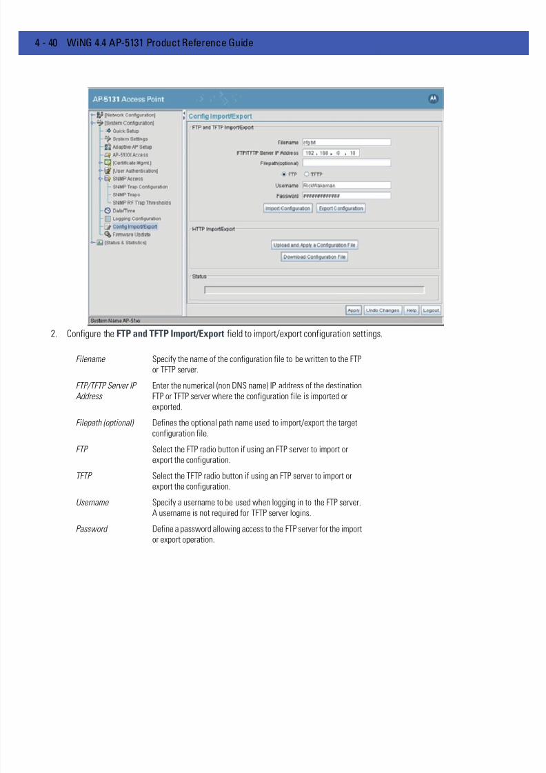
7/18/2019 Motorola AP 5131 Manual
http://slidepdf.com/reader/full/motorola-ap-5131-manual 112/613
4 - 40 WiNG 4.4 AP-5131 Product Reference Guide
2. Configure the FTP and TFTP Import/Export field to import/export configuration settings.
Filename Specify the name of the configuration file to be written to the FTP
or TFTP server.
FTP/TFTP Server IP
Address
Enter the numerical (non DNS name) IP address of the destination
FTP or TFTP server where the configuration file is imported or
exported.
Filepath (optional) Defines the optional path name used to import/export the target
configuration file.
FTP Select the FTP radio button if using an FTP server to import or
export the configuration.
TFTP Select the TFTP radio button if using an FTP server to import or
export the configuration.
Username Specify a username to be used when logging in to the FTP server.
A username is not required for TFTP server logins.
Password Define a password allowing access to the FTP server for the import
or export operation.

7/18/2019 Motorola AP 5131 Manual
http://slidepdf.com/reader/full/motorola-ap-5131-manual 113/613
System Configuration 4 - 41
3. Configure the HTTP Import/Export field to import/export AP-51x1 configuration settings using HTTP.
4. Refer to the Status field to assess the completion of the import/export operation.
Import Configuration Click the Import Configuration button to import the configuration
file from the server with the assigned filename and login
information. The system displays a confirmation window indicating
the administrator must log out of the AP-51x1 after the operation
completes for the changes to take effect. Click Yes to continue the
operation. Click No to cancel the configuration file import.
Export Configuration Click the Export Configuration button to export the configuration
file from the server with the assigned filename and login
information. If the IP mode is set to DHCP Client, IP address
information is not exported (true for both LAN1, LAN2 and the
WAN port). For LAN1 and LAN2, IP address information is only
exported when the IP mode is set to either static or DHCP Server.
For the WAN port, IP address information is only exported when the
This interface is a DHCP Client checkbox is not selected. For
more information on these settings, see Configuring the LAN
Interface on page 5-2 and Configuring WAN Settings on page 5-13 .
The system displays a confirmation window prompting the
administrator to log out of the AP-51x1 after the operationcompletes for the changes to take effect. Click Yes to continue the
operation. Click No to cancel the configuration file export.
CAUTION For HTTP downloads (exports) to be successful, pop-up messagesmust be disabled.
Upload and Apply A
Configuration File
Click the Upload and Apply A Configuration File button to
upload a configuration file to this access point using HTTP.
Download
Configuration File
Click the Download Configuration File button to download this
access point’s configuration file using HTTP.
7/18/2019 Motorola AP 5131 Manual
http://slidepdf.com/reader/full/motorola-ap-5131-manual 114/613
4 - 42 WiNG 4.4 AP-5131 Product Reference Guide
5. Click Apply to save the filename and Server IP information. The Apply button does not execute the import or exportoperation, only saves the settings entered.
6. Click Undo Changes (if necessary) to undo any changes made. Undo Changes reverts the settings displayed on ConfigImport/Export screen to the last saved configuration.
7. Click Logout to securely exit the AP-51x1 Motorola Solutions access point applet. A prompt displays confirming the logoutbefore the applet is closed.
Status After executing an operation (by clicking any of the buttons in the
window), check the Status field for a progress indicator and
messages about the success or errors in executing the Import/
Export operation. Possible status messages include:
ambiguous input before marker: line <number >
unknown input before marker: line <number>
ignored input after marker: line <number>
additional input required after marker: line <number>
invalid input length: line <number>
error reading input: line <number>
import file from incompatible hardware type: line <number>
[0] Import operation done
[1] Export operation done
[2] Import operation failed
[3] Export operation failed
[4] File transfer in progress
[5] File transfer failed
[6] File transfer done
Auto cfg update: Error in applying config
Auto cfg update: Error in getting config file
Auto cfg update: Aborting due to fw update failure
The <number> value appearing at the end of some messages
relates to the line of the configuration file where an error or
ambiguous input was detected.
CAUTION If errors occur when importing the configuration file, a parsingmessage displays defining the line number where the error occurred.The configuration is still imported, except for the error. Consequently,it is possible to import an invalid configuration. The user is required tofix the problem and repeat the import operation until an error-freeimport takes place.
NOTE Motorola Solutions recommends importing configuration files using theCLI. If errors occur during the import process, they display all at once andare easier to troubleshoot. The access point GUI displays errors one at atime, and troubleshooting can be a more time-consuming process.
NOTE When importing the configuration, a xxxxxbytes loaded status messageindicates the file was downloaded successfully. An IncompatibleHardware Type Error message indicates the configuration was not applieddue to a hardware compatibility issue between the importing andexporting devices.

7/18/2019 Motorola AP 5131 Manual
http://slidepdf.com/reader/full/motorola-ap-5131-manual 115/613
System Configuration 4 - 43
NOTE For a discussion on the implications of replacing an existing AP-4131deployment with an AP-5131 or AP-5181, see Replacing an AP-4131 withan AP-5131 or AP-5181 on page B-15 .

7/18/2019 Motorola AP 5131 Manual
http://slidepdf.com/reader/full/motorola-ap-5131-manual 116/613
4 - 44 WiNG 4.4 AP-5131 Product Reference Guide
4.10 Updating Device Firmware
Motorola Solutions periodically releases updated versions of the AP-51x1 device firmware to the Motorola Solutions Website. If the AP-51x1 firmware version displayed on the System Settings page (see Configuring System Settings on page4-3 ) is older than the version on the Web site, Motorola Solutions recommends updating the AP-51x1 to the latest firmwareversion for full feature functionality.
The access point’s automatic update feature updates the access point’s firmware and configuration file automaticallywhen the access point is reset or when the access point initiates a DHCP request.
The firmware is automatically updated each time firmware versions are found to be different between what is running onthe access point and the firmware file located on the server. The configuration file is automatically updated when theconfiguration file name on the server is different than the name of the file previously loaded on the access point or whenthe file version (on the server) is different than the version currently in use on the access point.
Additionally, the configuration version can be manually changed in the text file to cause the configuration to be appliedwhen required. The parameter name within the configuration file is “cfg-version-1.1-01.” The access point only checks thetwo characters after the third hyphen (01) when making a comparison. Change the last two characters to update the access
point’s configuration. The two characters can be alpha-numeric.Upgrading from a legacy to a new firmware version is a two step process requiring the same upgrade procedure to berepeated twice. The first upgrade will result in a bootloader change, and the second upgrade will result in the actualfirmware update. For subsequent upgrades, a single download will suffice. Using Auto Update, the access point willautomatically update itself twice when upgrading.
Upgrading to a new access point firmware baseline does not retain the configuration of the previous (lower version)firmware. Motorola Solutions recommends users export their 1.0 configuration for backup purposes prior to upgrading.
When downloading to a lower firmware version, all configuration settings are lost and the access point returns to factorydefault settings of the lower version.
For detailed update scenarios involving both a Windows DHCP and a Linux BootP server configuration, see Configuring
Automatic Updates using a DHCP or Linux BootP Server on page B-2 .
CAUTION Downgrading firmware from to a lower version, the access point
automatically reverts to default settings of the lower version,regardless of whether you are downloading the firmware manually orusing the automatic download feature. The automatic feature allowsthe user to download the configuration file at the same time, but sincethe firmware reverts to the default settings of the lower version, theconfiguration file is ignored.
NOTE An AP-5181 does not support any firmware versions prior to 1.1.1.0.

7/18/2019 Motorola AP 5131 Manual
http://slidepdf.com/reader/full/motorola-ap-5131-manual 117/613
System Configuration 4 - 45
If a firmware update is required, use the Firmware Update screen to specify a filename and define a file location forupdating the firmware.
To conduct a firmware update on the AP-51x1:
1. Export the AP-51x1 current configuration settings before updating the firmware to have the most recent settings availableafter the firmware is updated.
Refer to Importing/Exporting Configurations on page 4-39 for instructions on exporting the AP-51x1’s current configurationto have it available after the firmware is updated.
2. Select System Configuration - > Firmware Update from the AP-51x1 menu tree.
CAUTION Loaded and signed CA certificates will be lost when changing theaccess point’s firmware version using either the GUI or CLI. After acertificate has been successfully loaded, export it to a secure locationto ensure its availability after a firmware update.
If restoring the access point’s factory default firmware, you mustexport the certificate file BEFORE restoring the access point’s factorydefault configuration. Import the file back after the updated firmwareis installed. For information on using the access point CLI to importand export the access point’s configuration, seeAP51xx>admin(system.cmgr)> impcert on page 8-160 andAP51xx>admin(system.cmgr)> expcert on page 8-159 .
NOTE The firmware file must be available from an FTP or TFTP site to performthe update.
CAUTION Make sure a copy of the AP-51x1’s configuration is exported beforeupdating the firmware.

7/18/2019 Motorola AP 5131 Manual
http://slidepdf.com/reader/full/motorola-ap-5131-manual 118/613
4 - 46 WiNG 4.4 AP-5131 Product Reference Guide
3. Configure the DHCP Options checkboxes to enable/disable automatic firmware and/or configuration file updates.
DHCP options are used for out-of-the-box rapid deployment for Motorola Solutions wireless products. The following are thetwo options available on the access point:
• Enable Automatic Firmware Update
• Enable Automatic Configuration Update
Both DHCP options are enabled by default.
These options can be used to update newer firmware and configuration files on the access point. For more information onhow to configure a DHCP or BootP Server for the automatic upgrade process, see Usage Scenarios on page B-1.
The update is conducted over the LAN or WAN port depending on which server responds first to the access point’s requestfor an automatic update.

7/18/2019 Motorola AP 5131 Manual
http://slidepdf.com/reader/full/motorola-ap-5131-manual 119/613
System Configuration 4 - 47
If updating the access point manually, configure the Update Firmware fields as required to set a filename and targetfirmware file upload location for firmware updates.
4. Specify the name of the target firmware file within the Filename field.
5. If the target firmware file resides within a directory, specify a complete path for the file within the Filepath(optional) field
6. Enter an IP address for the FTP or TFTP server used for the update. Only numerical IP address names are supported, no DNScan be used.
7. Select FTP or TFTP to define whether the firmware file resides on a FTP or TFTP server.8. Set the following FTP or TFTP parameters:
• Username - Specify a username for the FTP server login.
• Password - Specify a password for FTP server login. Default is motorola. A blank password is not supported.
Enable Automatic
Firmware Update
Enable this checkbox to allow an automatic firmware update when
firmware versions are found to be different between what is
running on the access point and the firmware that resides on the
server. A firmware update will only occur if the access point is reset
or when the access point does a DHCP request.This feature is used in conjunction with DHCP/BootP options
configured on a DHCP or BootP server. For more information, see
Usage Scenarios on page B-1.
If this checkbox is not enabled, the firmware update is required to
be conducted manually.
Enable Automatic
Configuration Update
Select this checkbox to allow an automatic configuration update
when the configuration filenames are found to be different
between the filename loaded on the access point and the
configuration filename that resides on the server or when the
configuration file versions are found to be different between the
configuration file version loaded on the access point and the
configuration file that resides on server. A configuration updatewill only occur if the access point is reset or when the access point
does a DHCP request.
This feature is used in conjunction with DHCP/BootP options
configured on a DHCP or BootP server. For more information, see
Usage Scenarios on page B-1.
If this checkbox is not enabled, the configuration update is required
to be done manually.
CAUTION If using a Linux server configured to support the BootP “bf” option, anautomatic firmware update is not be triggered unless both the EnableAutomatic Firmware Update and Enable Automatic
Configuration Update options are selected. If the ConfigurationUpdate option is disabled, the access point will not download theconfiguration file. Without the configuration file, the access pointcannot parse for the firmware file name required to trigger thefirmware update.
NOTE Click Apply to save the settings before performing the firmware update.The user is not able to navigate the AP-51x1 user interface while thefirmware update is in process.
7/18/2019 Motorola AP 5131 Manual
http://slidepdf.com/reader/full/motorola-ap-5131-manual 120/613
4 - 48 WiNG 4.4 AP-5131 Product Reference Guide
9. Click the Perform Update button to initiate the update. Upon confirming the firmware update, the AP reboots andcompletes the update.
10. After the AP reboots, return to the Firmware Update screen. Check the Status field to verify whether the firmware updatewas successful. If an error occurs, one of the following error messages will display:
FAIL: auto fw update check
FAIL: network activity time out
FAIL: firmware check
FAIL: exceed memory limit
FAIL: authentication
FAIL: connection time out
FAIL: control channel error
FAIL: data channel error
FAIL: channel closed unexpected
FAIL: establish data channel
FAIL: accept data channel
FAIL: user interrupted
FAIL: no valid interface found
FAIL: conflict ip address
FAIL: command exchange time out
FAIL: invalid subnet number
11. Confirm the AP-51x1 configuration is the same as it was before the firmware update. If they are not, restore the settings.Refer to Importing/Exporting Configurations on page 4-39 for instructions on exporting the configuration back to the AP-51x1.
12. Click Apply to save the filename and filepath information entered into the Firmware Update screen. The Apply button doesnot execute the firmware, only saves the update settings entered.
13. Click Undo Changes (if necessary) to undo any changes made. Undo Changes reverts the settings displayed on FirmwareUpdate screen to the last saved configuration.
14. Click Logout to securely exit the AP-51x1 Access Point applet. A prompt displays confirming the logout before the applet isclosed.
4.10.1 Upgrade/Downgrade Considerations When upgrading or downgrading access point configurations between the 1.0.0.0-xx (or 1.0.1.0-xx) and 1.1.0.0-xxbaselines, the following should be taken into consideration as certain functionalities may not be available to the user afteran upgrade/downgrade:
• When downgrading from 1.1.1/1.1 to 1.0, the access point is configured to default values.
NOTE The access point must complete the reboot process to successfully update
the device firmware, regardless of whether the reboot is conducted usingthe GUI or CLI interfaces.
CAUTION Prior to upgrading/downgrading the access point’s configuration,ensure the access point’s current configuration has been exported to asecure location. Having the configuration available is recommended incase errors occur in the upgrade/downgrade process.

7/18/2019 Motorola AP 5131 Manual
http://slidepdf.com/reader/full/motorola-ap-5131-manual 121/613
System Configuration 4 - 49
• After a downgrade from 1.1/1.1.0 to 1.0.x.x, WLANs mapped to LAN2 would still be usable, but now only available onLAN1. Once upgraded back, those WLANs previously available on LAN2 would still be mapped to LAN2.
• If downgraded to the 1.0.0.0-xx baseline, and a restore factory defaults function is performed, only 1.0.0.0-xx defaultvalues are restored to their factory default values. The feature set unique to 1.1/1.1.1 can only be restored to factory
default when the access point is running 1.1.0.0-xx firmware.• An AP-5181 model access point does not support firmware prior to 1.1.1.0.
• Export either a CA or Self Certificate to a safe and secure location before upgrading or downgrading your access pointfirmware. If the certificate is not saved, it will be discarded and not available to the user after the upgrade ordowngrade. If discarded, a new certificate request would be required.
• Upgrading from v1.0.x.x to 1.1.x.x/1.1.1 is a two step process requiring the same upgrade procedure to be repeatedtwice. The first upgrade will result in a bootloader change, and the second upgrade will result in a firmware change.For subsequent upgrades, a single download will suffice. Using Auto Update, the access point will automaticallyupdate itself twice when upgrading. Upgrading from v1.0 to v1.1/v1.1.1 retains existing settings. Motorola Solutionsrecommends that users export their 1.0 configuration for backup purposes prior to upgrading. When downloading fromv1.1.1/v1.1 to v1.0, all configuration settings are lost and the access point returns to factory default settings.
NOTE For a discussion on the implications of replacing an existing AP-4131deployment with an AP-5131 or AP-5181, see Replacing an AP-4131 withan AP-5131 or AP-5181 on page B-15 .

7/18/2019 Motorola AP 5131 Manual
http://slidepdf.com/reader/full/motorola-ap-5131-manual 122/613
4 - 50 WiNG 4.4 AP-5131 Product Reference Guide

7/18/2019 Motorola AP 5131 Manual
http://slidepdf.com/reader/full/motorola-ap-5131-manual 123/613
CHAPTER 5 NETWORK CONFIGURATION
Refer to the following for network management configuration activities supported by the access point user interface:
• Configuring the LAN Interface
• Configuring WAN Settings
• Enabling Wireless LANs (WLANs)
• Configuring WIPS Server Settings
• Configuring Router Settings

7/18/2019 Motorola AP 5131 Manual
http://slidepdf.com/reader/full/motorola-ap-5131-manual 124/613
5 - 2 WiNG 4.4 AP-5131 Product Reference Guide
5.1 Configuring the LAN Interface
The AP-51x1 has one physical LAN port supporting two unique LAN interfaces. The AP-51x1 LAN port has its own MACaddress. The LAN port MAC address is always the value of the AP-51x1 WAN port MAC address plus 1. The LAN and WANport MAC addresses can be located within the LAN and WAN Stats screens.
For information on locating the access point’s MAC addresses, see Viewing WAN Statistics on page 7-3 and Viewing LANStatistics on page 7-6 .
Use the LAN Configuration screen to enable one (or both) of the access point’s LAN interfaces, assign them names,define which LAN is currently active on the access point Ethernet port and assign a timeout value to disable the LANconnection if no data traffic is detected within a defined interval.
To configure the AP-51x1 LAN interface:
1. Select Network Configuration -> LAN from the AP-51x1 menu tree..
2. Configure theLAN Settings field to enable the AP-51x1 LAN1 and/or LAN2 interface, assign a timeout value, enable 802.1qtrunking, configure WLAN mapping and enable 802.1x port authentication.
CAUTION If deploying the access point as an AAP with a remote layer 3configuration and the AAP is set for switch auto discovery(primary/standby), the access point will un-adopt from its switch aftera few moments. To remedy this problem, ensure LAN1 has 802.1q
trunking enabled and the correct management VLAN defined.

7/18/2019 Motorola AP 5131 Manual
http://slidepdf.com/reader/full/motorola-ap-5131-manual 125/613
Network Configuration 5 - 3
3. Refer to the LAN Ethernet Timeout field to define how LAN Ethernet inactivity is processed by the access point.
Use the Ethernet Port Timeout drop-down menu to define how the access point interprets inactivity for the LAN assignedto the Ethernet port. When Enabled is selected, the access point uses the value defined in the Sec. box (default is 30seconds). Selecting Disabled allows the LAN to use the Ethernet port for an indefinite timeout period.
4. Refer to the 802.1x Port Authentication field if using port authentication over the access point’s LAN port.
The access point only supports 802.1x authentication over its LAN port. The access point behaves as an 802.1x supplicantto authenticate to a server on the network. If using 802.1x authentication, enter the authentication server user name andpassword. The default password is “motorola.” For information on enabling and configuring authentication schemes on theaccess point, see Enabling Authentication and Encryption Schemes on page 6-5 .
5. Use the Port Settings field to define how the access point manages throughput over the LAN port.
Enable Select the LAN1 and/or LAN2 checkbox to allow the forwarding of
data traffic over the specified LAN connection. The LAN1
connection is enabled by default, but both LAN interfaces can be
enabled simultaneously. The LAN2 setting is disabled by default.
LAN Name Use the LAN Name field to modify the existing LAN name. LAN1
and LAN2 are the default names assigned to the LANs until
modified by the user.
Ethernet Port The Ethernet Port radio buttons allow you to select one of the two
available LANs as the LAN actively transmitting over the access
point’s LAN port. Both LANs can be active at any given time, but
only one can transmit over the access point’s physical LAN
connection, thus the selected LAN has priority.
Enable 802.1q
Trunking
Select the Enable 802.1q Trunking checkbox to enable the LAN
to conduct VLAN tagging. If selected, click the WLAN Mappingbutton to configure mappings between individual WLANs and
LANs. If enabled, the access point is required to be connected to atrunked port.
VLAN Name Click the VLAN Name button to launch the VLAN Name screen
to create VLANs and assign them VLAN IDs. For more information,
see Configuring VLAN Support on page 5-4 .
WLAN Mapping Click the WLAN Mapping button to launch the VLANConfiguration screen to map existing WLANs to one of the two
LANs and define the WLAN’s VLAN membership (up to 16
mappings are possible per access point). For more information, see
Configuring VLAN Support on page 5-4 .
7/18/2019 Motorola AP 5131 Manual
http://slidepdf.com/reader/full/motorola-ap-5131-manual 126/613
5 - 4 WiNG 4.4 AP-5131 Product Reference Guide
.
6. Click Apply to save any changes to the LAN Configuration screen. Navigating away from the screen without clicking the
Apply button results in all changes to the screen being lost if the prompts are ignored.7. Click Undo Changes (if necessary) to undo any changes made. Undo Changes reverts the settings displayed on the LAN
configuration screen to the last saved configuration.
8. Click Logout to securely exit the AP-51x1 Access Point applet. A prompt displays confirming the logout before the applet isclosed.
5.1.1 Configuring VLAN Support
A Virtual Local Area Network (VLAN) is a means to electronically separate data on the same AP-51x1 from a singlebroadcast domain into separate broadcast domains. The AP-51x1 can group devices on one or more WLANs so that theycan communicate as if they were attached to the same wire, when in fact they are located on a different LAN segment.Because VLANs are based on logical instead of physical connections, they are extremely flexible. By using a VLAN, you
can group by logical function instead of physical location. A maximum of 16 VLANs can be supported on the access point(regardless of the access point being single or dual-radio model). An administrator can map 16 WLANs to 16 VLANs andenable or disable dynamic VLAN assignment.
VLANs enable organizations to share network resources in various network segments within large areas (airports,shopping malls, etc.). A VLAN is a group of clients with a common set of requirements independent of their physicallocation. VLANs have the same attributes as physical LANs, but they enable system administrators to group MUs evenwhen they are not members of the same network segment.
Auto Negotiation Select the Auto Negotiation checkbox to enable the access point
to automatically exchange information (over its LAN port) about
data transmission speed and duplex capabilities.
Auto negotiation is helpful when using the access point in an
environment where different devices are connected anddisconnected on a regular basis.
Selecting Auto Negotiate disables the Mbps and duplex checkbox
options.
100 Mbps Select this option to establish a 100 Mbps data transfer rate for the
selected half duplex or full duplex transmission over the access
point’s LAN port. This option is not available if Auto Negotiation is
selected.
10 Mbps Select this option to establish a 10 Mbps data transfer rate for the
selected half duplex or full duplex transmission over the access
point’s LAN port. This option is not available if Auto Negotiation is
selected.half duplex Select this option to transmit data to and from the access point, but
not at the same time. Using a half duplex transmission, the access
point can send data over its LAN port then immediately receive
data from the same direction in which the data was transmitted.
Like a full-duplex transmission, a half-duplex transmission can
carry data in both directions, just not at the same time.
full duplex Select this option to transmit data to and from the access point at
the same time. Using full duplex, the access point can send data
over its LAN port while receiving data as well.

7/18/2019 Motorola AP 5131 Manual
http://slidepdf.com/reader/full/motorola-ap-5131-manual 127/613
Network Configuration 5 - 5
The AP-51x1 assignment of VLANs can be implemented using Static or Dynamic assignments (often referred to asmemberships) for individual WLANs. Both methods have their advantages and disadvantages. Static VLAN membership isperhaps the most widely used method because of the relatively small administration overhead and security it provides.With Static VLANs, you manually assign individual WLANs to individual VLANs.
Although static VLANs are the most common form of VLAN assignments, dynamic VLAN assignment is possible per WLAN.Configuring dynamic VLANs entail the AP-51x1 sending a DHCP request for device information (such as an IP address).Additional information (such as device MAC address information) is sent to the AP-51x1. The AP-51x1 sends this MACaddress to a host housing a copy of the Dynamic VLAN database. This database houses the records of MAC addresses andVLAN assignments. The VLAN database looks up the MAC to determine what VLAN is assigned to it. If it is not in thedatabase, it simply uses a default VLAN assignment. The VLAN assignment is sent to the AP-51x1. The AP-51x1 then mapsthe target WLAN for the assigned VLAN and traffic passes normally, allowing for the completion of the DHCP request and
further traffic.
To create new VLANs or edit the properties of an existing VLAN:
1. Select Network Configuration -> LAN from the AP-51x1 menu tree.
2. Ensure the Enable 802.1q Trunking button is selected from within the LAN Setting field.
Trunk links are required to pass VLAN information between destinations. A trunk port is by default a member of all the VLANsexisting on the AP-51x1 and carry traffic for all those VLANs. Trunking is a function that must be enabled on both sides of alink.
3. Select the VLAN Name button.
The VLAN name screen displays. The first time the screen is launched a default VLAN name of 1 and a default VLAN ID of1 display. The VLAN name is auto-generated once the user assigns a VLAN ID. However, the user has the option of re-assigning a name to the VLAN using New VLAN and Edit VLAN screens.
NOTE A WLAN supporting a mesh network does not need to be assigned to aparticular VLAN, as all the traffic proliferating the mesh network isalready trunked. However, if MUs are to be connected to the Mesh WLAN,the WLAN will need to be tied to a VLAN.

7/18/2019 Motorola AP 5131 Manual
http://slidepdf.com/reader/full/motorola-ap-5131-manual 128/613
5 - 6 WiNG 4.4 AP-5131 Product Reference Guide
To create a new VLAN, click the Add button, to edit the properties of an existing VLAN, click the Edit button.
4. Assign a unique VLAN ID (from 1 to 4095) to each VLAN added or modified.
The VLAN ID associates a frame with a specific VLAN and provides the information the AP-51x1 needs to process the frameacross the network. Therefore, it may be practical to assign a name to a VLAN representative or the area or type of networktraffic it represents.
A business may have offices in different locations and want to extend an internal LAN between the locations. An AP-51x1
managed infrastructure could provide this connectivity, but it requires VLAN numbering be managed carefully to avoidconflicts between two VLANs with the same ID.
5. Define a 32 ASCII character maximum VLAN Name.
Enter a unique name that identifies members of the VLAN. Motorola Solutions recommends selecting the name carefully, asthe VLAN name should signify a group of clients with a common set of requirements independent of their physical location.
6. Click Apply to save the changes to the new or modified VLAN.
7. From the LAN Configuration screen, click the WLAN Mapping button. The Mapping Configuration screen displays.
8. Enter a Management VLAN Tag for LAN1 and LAN2.
The Management VLAN uses a default tag value of 1. The Management VLAN is used to distinguish VLAN traffic flows forthe LAN. The trunk port marks the frames with special tags as they pass between the AP-51x1 and its destination, thesetags help distinguish data traffic.
Authentication servers (such as Radius and Kerberos) must be on the same Management VLAN. Additionally, DHCP andBOOTP servers must be on the same Management VLAN as well.
9. Define a Native VLAN Tag for LAN1 and LAN2.

7/18/2019 Motorola AP 5131 Manual
http://slidepdf.com/reader/full/motorola-ap-5131-manual 129/613
Network Configuration 5 - 7
A trunk port configured with 802.1Q tagging can receive both tagged and untagged traffic. By default, the access pointforwards untagged traffic with the native VLAN configured for the port. The Native VLAN is VLAN 1 by default. MotorolaSolutions suggests leaving the Native VLAN set to 1 as other layer 2 devices also have their Native VLAN set to 1.
10. Use the LAN drop-down menu to map one of the two LANs to the WLAN listed to the left. With this assignment, the WLAN
uses this assigned LAN interface.11. Select the Dynamic checkboxes (under the Mode column) to configure the VLAN mapping as a dynamic VLAN.
Using Dynamic VLAN assignments, a VMPS (VLAN Management Policy Server) dynamically assigns VLAN ports. TheAP-51x1 uses a separate server as a VMPS server. When a frame arrives on the AP-51x1, it queries the VMPS for the VLANassignment based on the source MAC address of the arriving frame.
If statically mapping VLANs, leave the Dynamic checkbox specific to the target WLAN and its intended VLAN unselected.The administrator is then required to configure VLAN memberships manually.
The Dynamic checkbox is enabled only when a WLAN is having EAP configured. Otherwise, the checkbox is disabled.
12. Use the VLAN drop-down menu to select the name of the target VLAN to map to the WLAN listed on the left-hand side ofthe screen.
Motorola Solutions recommends mapping VLANs strategically in order to keep VLANs tied to the discipline they most closelymatch. For example, If WLAN1 is comprised of MUs supporting the sales area, then WLAN1 should be mapped to sales if asales VLAN has been already been created.
13. Click Apply to return to the VLAN Name screen. Click OK to return to the LAN screen. Once at the LAN screen, click Applyto re-apply your changes.
5.1.2 Configuring LAN1 and LAN2 Settings
Both LAN1 and LAN2 have separate sub-screens to configure the DHCP settings used by the LAN1 and LAN2 interfaces.Within each LAN screen is a button to access a sub-screen to configure advanced DHCP settings for that LAN. For moreinformation, see Configuring Advanced DHCP Server Settings on page 5-10 . Additionally, LAN1 and LAN2 each haveseparate Type Filter submenu items used to prevent specific (an potentially unneccesary) frames from being processed,
for more information, see Setting the Type Filter Configuration on page 5-10 .
To configure unique settings for either LAN1 or LAN2:
1. Select Network Configuration -> LAN -> LAN1 (or LAN2) from the AP-51x1 menu tree.

7/18/2019 Motorola AP 5131 Manual
http://slidepdf.com/reader/full/motorola-ap-5131-manual 130/613
5 - 8 WiNG 4.4 AP-5131 Product Reference Guide
2. Configure the DHCP Configuration field to define the DHCP settings used for the LAN.
NOTE Motorola Solutions recommends the WAN and LAN ports should not bothbe configured as DHCP clients.
This interface is a
DHCP Client
Select this button to enable DHCP to set network address
information via this LAN1 or LAN2 connection. This is
recommended if the AP-51x1 resides within a large corporate
network or the Internet Service Provider (ISP) uses DHCP. This
setting is enabled for LAN1 by default.
DHCP is a protocol that includes mechanisms for IP address
allocation and delivery of host-specific configuration parameters
from a DHCP server to a host. If DHCP Client is selected, the first
DHCP or BOOTP server to respond sets the IP address and network
address values since DHCP and BOOTP are interoperable.
This interface is a
BOOTP Client
Select this button to enable BOOTP to set AP-51x1 network address
information via this LAN1 or LAN2 connection.
When selected, only BOOTP responses are accepted by the
AP-51x1. If both DHCP and BOOTP services are required, do not
select BOOTP Client.
This interface uses
static IP Address
Select the This interface uses static IP Address button, and
manually enter static network address information in the areas
provided.
This interface is a
DHCP Server
The AP-51x1 can be configured to function as a DHCP server over
the LAN1 or LAN2 connection. Select the This interface is aDHCP Server button and manually enter static network address
information in the areas provided.

7/18/2019 Motorola AP 5131 Manual
http://slidepdf.com/reader/full/motorola-ap-5131-manual 131/613
Network Configuration 5 - 9
3. Click Apply to save any changes to the LAN1 or LAN2 screen. Navigating away from the screen without clicking the Applybutton results in all changes to the screen being lost if the prompts are ignored.
4. Click Undo Changes (if necessary) to undo any changes made. Undo Changes reverts the settings displayed on the LAN1or LAN2 screen to the last saved configuration.
5. Click Logout to securely exit the Access Point applet. A prompt displays confirming the logout before the applet is closed.
Address Assignment
Range
Use the address assignment parameter to specify a range of
numerical (non DNS name) IP addresses reserved for mapping
client MAC addresses to IP addresses. If a manually (static)
mapped IP address is within the IP address range specified, that IP
address could still be assigned to another client. To avoid this,
ensure all statically mapped IP addresses are outside of the IPaddress range assigned to the DHCP server.
Advanced DHCP
Server
Click the Advanced DHCP Server button to display a screen used
for generating a list of static MAC to IP address mappings for
reserved clients. A separate screen exists for each of the LANs. For
more information, see Configuring Advanced DHCP Server Settings
on page 5-10 .
IP Address The network-assigned numerical (non DNS name) IP address of the
AP-51x1.
Network Mask The first two sets of numbers specify the network domain, the next
set specifies the subset of hosts within a larger network. These
values help divide a network into subnetworks and simplify routingand data transmission. The subnet mask defines the size of the
subnet.
Default Gateway The Default Gateway parameter defines the numerical (non DNS
name) IP address of a router the AP-51x1 uses on the Ethernet as
its default gateway.
Domain Name Enter the name assigned to the primary DNS server.
Primary DNS Server Enter the Primary DNS numerical (non DNS name) IP address.
Secondary DNS
Server
Motorola Solutions recommends entering the numerical IP address
of an additional DNS server (if available), used if the primary DNS
server goes down. A maximum of two DNS servers can be used.
WINS Server Enter the numerical (non DNS name) IP address of the WINS server.
WINS is a Microsoft NetBIOS name server. Using a WINS server
eliminates the broadcasts needed to resolve computer names to IP
addresses by providing a cache or database of translations.
Mesh STP
Configuration
Click the Mesh STP Configuration button to define bridge
settings for this specific LAN. Each of the access point’s two LANs
can have a separate mesh configuration. As the Spanning Tree
Protocol (STP) mentions, each mesh network maintains hello,
forward delay and max age timers. These settings can be used as
is using the current default settings, or be modified. However, if
these settings are modified, they need to be configured for the LAN
connecting to the mesh network WLAN.For information on mesh networking capabilities, see Configuring
Mesh Networking on page 9-1. If new to mesh networking and in
need of an overview, see Mesh Networking Overview on page 9-1.

7/18/2019 Motorola AP 5131 Manual
http://slidepdf.com/reader/full/motorola-ap-5131-manual 132/613
5 - 10 WiNG 4.4 AP-5131 Product Reference Guide
5.1.2.1 Configuring Advanced DHCP Server Settings
Use the Advanced DHCP Server screen to specify (reserve) static (or fixed) IP addresses for specific devices. Everywireless, 802.11x-standard device has a unique Media Access Control (MAC) address. This address is the device's hard-coded hardware number (shown on the bottom or back). An example of a MAC address is 00:A0:F8:45:9B:07.
The DHCP server can grant an IP address for as long as it remains in active use. The lease time is the number of secondsan IP address is reserved for re-connection after its last use. Using very short leases, DHCP can dynamically reconfigurenetworks in which there are more computers than available IP addresses. This is useful, for example, in education andcustomer environments where MU users change frequently. Use longer leases if there are fewer users.
To generate a list of client MAC address to IP address mappings for the AP-51x1:
1. Select Network Configuration -> LAN -> LAN1 (or LAN2) from the AP-51x1 menu tree.
2. Click the Advanced DHCP Server button from within the LAN1 or LAN2 screen.
3. Specify a lease period in seconds for available IP addresses using the DHCP Lease Time (Seconds) parameter. An IPaddress is reserved for re-connection for the length of time you specify. The default interval is 86400 seconds.
4. Click the Add button to create a new table entry within the Reserved Clients field.
If a statically mapped IP address is within the IP address range in use by the DHCP server, that IP address may still beassigned to another client. To avoid this, ensure all statically mapped IP addresses are outside of the IP address rangeassigned to the DHCP server.
If multiple entries exist within the Reserved Clients field, use the scroll bar to the right of the window to navigate.
5. Click the Del (delete) button to remove a selected table entry.
6. Click OK to return to the LAN1 or LAN2 page, where the updated settings within the Advanced DHCP Server screen canbe saved by clicking the Apply button.
7. Click Cancel to undo any changes made. Undo Changes reverts the settings displayed to the last saved configuration.
5.1.2.2 Setting the Type Filter Configuration
Each AP-51x1 LAN (either LAN1 or LAN2) can keep a list of frame types that it forwards or discards. The Type Filteringfeature prevents specific (a potentially unneccesary) frames from being processed by the AP-51x1 in order to improve

7/18/2019 Motorola AP 5131 Manual
http://slidepdf.com/reader/full/motorola-ap-5131-manual 133/613
Network Configuration 5 - 11
throughput. These include certain broadcast frames from devices that consume bandwidth, but are unnecessary toAP-51x1 operations.
Use the Ethernet Type Filter Configuration screen to build a list of filter types and configure them as either allowed ordenied for use with the this particular LAN.
To configure type filtering on the AP-51x1:
1. Select Network Configuration-> LAN -> LAN1 (or LAN2)-> Type Filter from the AP-51x1 menu tree.
The Ethernet Type Filter Configuration screen displays for the LAN. No Ethernet types are displayed (by default) whenthe screen is first launched.
2. Use the all ethernet types, except drop-down menu to designate whether the Ethernet Types defined for the LAN areallowed or denied for use by the AP-51x1.
3. To add an Ethernet type, click the Add button.
The Add Ethernet Type screen displays. Use this screen to add one type filter option at a time, for a list of up to 16 entries
Packet types supported for the type filtering function include 16-bit DIX Ethernet types as well as Motorola Solutionsproprietary types. Select an Ethernet type from the drop down menu, or enter the Ethernet type’s hexadecimal value. Seeyour System Administrator if unsure of the implication of adding or omitting a type from the list for either LAN1 or LAN2.
4. To optionally delete a type filtering selection from the list, highlight the packet type and click the Delete button.

7/18/2019 Motorola AP 5131 Manual
http://slidepdf.com/reader/full/motorola-ap-5131-manual 134/613
5 - 12 WiNG 4.4 AP-5131 Product Reference Guide
5. Click Apply to save any changes to the LAN1 or LAN2 Ethernet Type Filter Configuration screen. Navigating away from thescreen without clicking Apply results in all changes to the screens being lost.
6. Click Cancel to securely exit the LAN1 or LAN2 Ethernet Type Filter Configuration screen without saving your changes.
7. Click Logout to securely exit the Access Point applet. A prompt displays confirming the logout before the applet is closed.

7/18/2019 Motorola AP 5131 Manual
http://slidepdf.com/reader/full/motorola-ap-5131-manual 135/613
Network Configuration 5 - 13
5.2 Configuring WAN Settings
A Wide Area Network (WAN) is a widely dispersed telecommunications network. The AP-51x1 includes one WAN port.The AP-51x1 WAN port has its own MAC address. In a corporate environment, the WAN port might connect to a largercorporate network. For a small business, the WAN port might connect to a DSL or cable modem to access the Internet.
Use the WAN screen to set the WAN IP configuration and Point-to-Point Protocol over Ethernet (PPPoE) parameters.
To configure WAN settings for the AP-51x1:
1. Select Network Configuration -> WAN from the AP-51x1 menu tree.
2. Refer to the WAN IP Configuration field to enable the WAN interface, and set network address information for the WANconnection.
NOTE Motorola Solutions recommends that the WAN and LAN ports should notboth be configured as DHCP clients.

7/18/2019 Motorola AP 5131 Manual
http://slidepdf.com/reader/full/motorola-ap-5131-manual 136/613
5 - 14 WiNG 4.4 AP-5131 Product Reference Guide
Enable WAN Interface Select the Enable WAN Interface checkbox to enable a
connection between the AP-51x1 and a larger network or outside
world through the WAN port.
Disable this option to effectively isolate the AP-51x1’s WAN. No
connections to a larger network or the Internet are possible. MUscannot communicate beyond the LAN.
By default, the WAN port is static with an IP address of 10.1.1.1.
This interface is a
DHCP Client
This checkbox enables DHCP for the AP-51x1 WAN connection.
This is useful, if the larger corporate network or Internet Service
Provider (ISP) uses DHCP.
DHCP is a protocol that includes mechanisms for IP address
allocation and delivery of host-specific configuration parameters
from a DHCP server to a host. Some of these parameters are IP
address, network mask, and gateway.
If DHCP client mode is enabled, the other WAN IP configuration
parameters are grayed out.
IP Address Specify a numerical (non DNS name) IP address for the AP-51x1’s
WAN connection. This address defines the AP's presence on a
larger network or on the Internet.
Obtain a static (dedicated) IP address from the ISP or network
administrator. An IP address uses a series of four numbers
expressed in dot notation, for example, 190.188.12.1.
Subnet Mask Specify a subnet mask for the AP-51x1’s WAN connection. This
number is available from the ISP for a DSL or cable-modem
connection, or from an administrator if the AP-51x1 connects to a
larger network.
A subnet mask uses a series of four numbers expressed in dot
notation (similar to an IP address). For example, 255.255.255.0 is avalid subnet mask.
Default Gateway Specify the gateway address for the AP-51x1’s WAN connection.
The ISP or a network administrator provides this address.
Primary DNS Server Specify the address of a primary Domain Name System (DNS)
server. The ISP or a network administrator provides this address.
A DNS server translates a domain name (for example,
www.motorola.com) into an IP address that networks can use.
Secondary DNS
Server
Specify the address of a secondary DNS server if one is used. A
secondary address is recommended if the primary DNS server goes
down.

7/18/2019 Motorola AP 5131 Manual
http://slidepdf.com/reader/full/motorola-ap-5131-manual 137/613
Network Configuration 5 - 15
3. Use the Port Settings field to define how the access point manages throughput over the WAN port.
More IP Addresses Click the More IP Addresses button to specify additional static IP
addresses for the AP-51x1. Additional IP addresses are required
when users within the WAN need dedicated IP addresses, or when
servers need to be accessed (addressed) by the outside world. The
More IP Addresses screen allows the administrator to enter up to
seven additional WAN IP addresses for the AP-51x1 WAN. Onlynumeric, non-DNS names can be used.
If PPP over Ethernet is enabled from within the WAN screen, the
VPN WAN IP Configuration portion of the More IP Addresses
screen is enabled. Enter the IP address and subnet mask used to
provide the PPPoE connection over the access point’s WAN port.
Ensure the IP address is a numerical (non DNS) name.
Refresh Click the Refresh button to update the network address
information displayed within the WAN IP Configuration field.
Enable Use the checkbox to enable Point-to-Point over Ethernet (PPPoE) for
a high-speed connection that supports this protocol. Most DSL
providers are currently using or deploying this protocol.
PPPoE is a data-link protocol for dialup connections. PPPoE allows
a host PC to use a broadband modem (DSL) for access to high-
speed data networks.
Username Specify a username entered when connecting to the ISP. When the
Internet session begins, the ISP authenticates the username.
Password Specify a password entered when connecting to the ISP. When the
Internet session starts, the ISP authenticates the password.
PPPoE State Displays the current connection state of the PPPoE client. When aPPPoE connection is established, the status displays Connected. When no PPPoE connection is active, the status displays
Disconnected.
Keep-Alive Select the Keep-Alive checkbox to maintain the WAN connection
indefinitely (no timeout interval). Some ISPs terminate inactive
connections. Enabling Keep-Alive keeps the AP-51x1’s WAN
connection active, even when there is no traffic. If the ISP drops the
connection after an idle period, the AP-51x1 automatically re-
establishes the connection to the ISP. Enabling Keep-Alive mode
disables (grays out) the Idle Time field.

7/18/2019 Motorola AP 5131 Manual
http://slidepdf.com/reader/full/motorola-ap-5131-manual 138/613
5 - 16 WiNG 4.4 AP-5131 Product Reference Guide
4. Click Apply to save any changes to the WAN screen. Navigating away from the screen without clicking the Apply buttonresults in all changes to the screen being lost.
5. Click Undo Changes (if necessary) to undo any changes made. Undo Changes reverts the settings displayed on the WANscreen to the last saved configuration.
6. Click Logout to securely exit the Access Point applet. A prompt displays confirming the logout before the applet is closed.
5.2.1 Configuring Network Address Translation (NAT) Settings
Network Address Translation (NAT) converts an IP address in one network to a different IP address or set of IP addressesin another network. The AP-51x1 router maps its local (inside) network addresses to WAN (outside) IP addresses, andtranslates the WAN IP addresses on incoming packets to local IP addresses. NAT is useful because it allows theauthentication of incoming and outgoing requests, and minimizes the number of WAN IP addresses needed when a rangeof local IP addresses is mapped to each WAN IP address. NAT can be applied in one of two ways:
• One-to-one mapping with a private side IP address
The private side IP address can belong to any of the private side subnets.
• One-to-many mapping with a configurable range of private side IP addresses
Ranges can be specified from each of the private side subnets.
To configure IP address mappings for the AP-51x1:
1. Select Network Configuration -> WAN -> NAT from the AP-51x1 menu tree.
Idle Time (seconds) Specify an idle time in seconds to limit how long the AP-51x1’s
WAN connection remains active after outbound and inbound traffic
is not detected. The Idle Time field is grayed out if Keep-Alive is
enabled.
Authentication Type Use the Authentication Type menu to specify the authenticationprotocol(s) for the WAN connection. Choices include None, PAP or
CHAP, PAP, or CHAP.
Password Authentication Protocol (PAP) and Challenge Handshake
Authentication Protocol (CHAP) are competing identify-verification
methods.
PAP sends a username and password over a network to a server
that compares the username and password to a table of authorized
users. If the username and password are matched in the table,
server access is authorized. WatchGuard products do not support
the PAP protocol because the username and password are sent as
clear text that a hacker can read.
CHAPuses secret information and mathematical algorithms to
send a derived numeric value for login. The login server knows the
secret information and performs the same mathematical
operations to derive a numeric value. If the results match, server
access is authorized. After login, one of the numbers in the
mathematical operation is changed to secure the connection. This
prevents any intruder from trying to copy a valid authentication
session and replaying it later to log in.

7/18/2019 Motorola AP 5131 Manual
http://slidepdf.com/reader/full/motorola-ap-5131-manual 139/613
Network Configuration 5 - 17
2. Configure the Address Mappings field to generate a WAN IP address, define the NAT type and set outbound/inbound NATmappings.
WAN IP Address The WAN IP addresses on the NAT screen are dynamically
generated from address settings applied on the WAN screen.
NAT Type Specify the NAT Type as 1 to 1 to map a WAN IP address to a single
host (local) IP address. 1 to 1 mapping is useful when users needdedicated addresses, and for public-facing servers connected to
the AP-51x1.
Set the NAT Type as 1 to Many to map a WAN IP address to
multiple local IP addresses. This displays the mappings button in
the adjacent Outbound Mappings field. This button displays a
screen for mapping the LAN IP addresses that are associated with
each subnet.
Define the NAT Type as none when routable IP addresses are used
on the internal network.
Outbound Mappings When 1 to 1 NAT is selected, a single IP address can be entered in
the Outbound Mappings area. This address provides a 1 to 1
mapping of the WAN IP address to the specified IP address.When 1 to Many is selected as the NAT Type, the Outbound
Mappings area displays a mappings button. Click the button to
select the LAN1 or LAN2 IP address used to set the outbound IP
address or select none to exclude the IP address.
If none is selected as the NAT Type, The Outbound Mappings area
is blank.
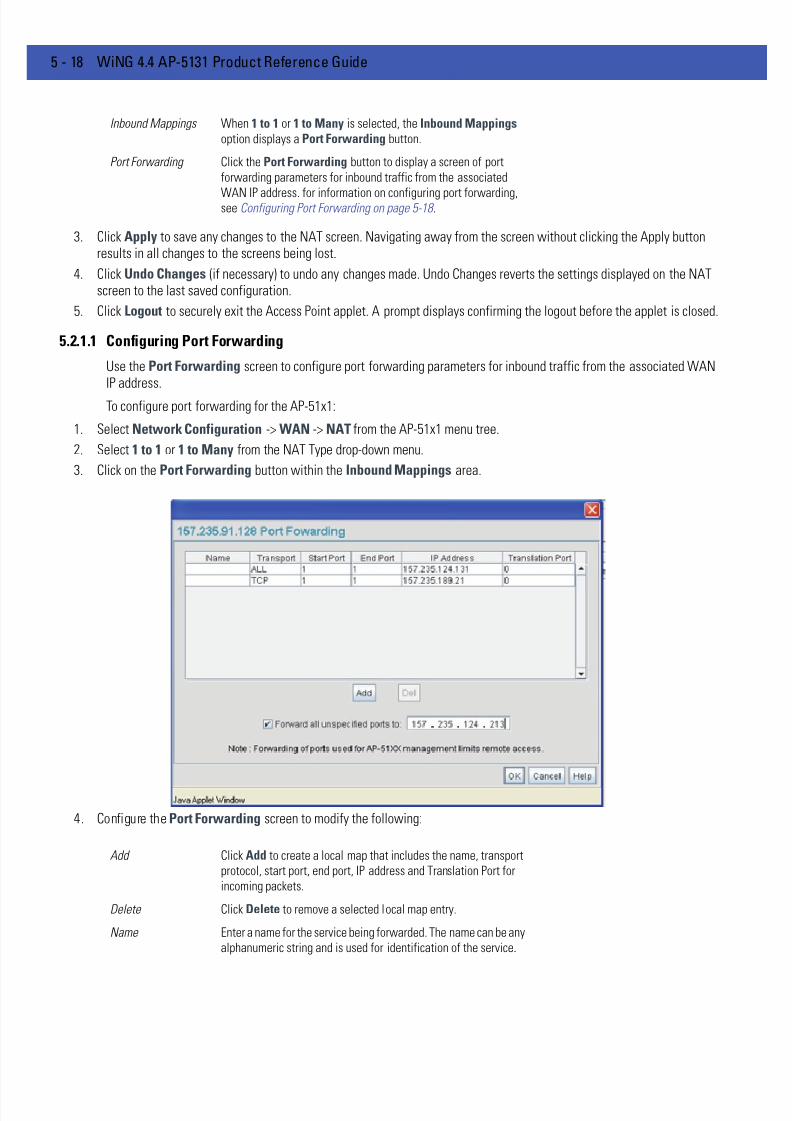
7/18/2019 Motorola AP 5131 Manual
http://slidepdf.com/reader/full/motorola-ap-5131-manual 140/613
5 - 18 WiNG 4.4 AP-5131 Product Reference Guide
3. Click Apply to save any changes to the NAT screen. Navigating away from the screen without clicking the Apply buttonresults in all changes to the screens being lost.
4. Click Undo Changes (if necessary) to undo any changes made. Undo Changes reverts the settings displayed on the NATscreen to the last saved configuration.
5. Click Logout to securely exit the Access Point applet. A prompt displays confirming the logout before the applet is closed.
5.2.1.1 Configuring Port Forwarding
Use the Port Forwarding screen to configure port forwarding parameters for inbound traffic from the associated WANIP address.
To configure port forwarding for the AP-51x1:
1. Select Network Configuration -> WAN -> NAT from the AP-51x1 menu tree.
2. Select 1 to 1 or 1 to Many from the NAT Type drop-down menu.
3. Click on the Port Forwarding button within the Inbound Mappings area.
4. Configure the Port Forwarding screen to modify the following:
Inbound Mappings When 1 to 1 or 1 to Many is selected, the Inbound Mappings
option displays a Port Forwarding button.
Port Forwarding Click the Port Forwarding button to display a screen of port
forwarding parameters for inbound traffic from the associated
WAN IP address. for information on configuring port forwarding,see Configuring Port Forwarding on page 5-18 .
Add Click Add to create a local map that includes the name, transport
protocol, start port, end port, IP address and Translation Port for
incoming packets.
Delete Click Delete to remove a selected local map entry.
Name Enter a name for the service being forwarded. The name can be any
alphanumeric string and is used for identification of the service.
7/18/2019 Motorola AP 5131 Manual
http://slidepdf.com/reader/full/motorola-ap-5131-manual 141/613
Network Configuration 5 - 19
5. Click OK to return to the NAT screen. Within the NAT screen, click Apply to save any changes made on the Port Forwardingscreen.
6. Click Cancel to undo any changes made on Port Forwarding screen. This reverts all settings for the Port Forwarding screento the last saved configuration.
5.2.2 Configuring Dynamic DNS
The access point supports the Dynamic DNS service. Dynamic DNS (or DynDNS) is a feature offered by www.dyndns.comwhich allows the mapping of domain names to dynamically assigned IP addresses via the WAN port. When thedynamically assigned IP address of a client changes, the new IP address is sent to the DynDNS service and traffic for thespecified domain(s) is routed to the new IP address.
To configure dynamic DNS for the AP-51x1:
1. Select Network Configuration -> WAN -> DynDNS from the AP-51x1 menu tree.
Transport Use the Transport pull-down menu to specify the transport
protocol used in this service. The choices are ALL, TCP, UDP , ICMP ,
AH , ESP, and GRE.
Start Port and End Port Enter the port or ports used by the port forwarding service. To
specify a single port, enter the port number in the Start Port area.To specify a range of ports, use both the Start Port and End Port options to enter the port numbers. For example, enter 110 in the
Start Port field and 115 in the End Port field.
IP Address Enter the numerical (non DNS name) IP address to which the
specified service is forwarded. This address must be within the
specified NAT range for the associated WAN IP address.
Translation Port Specify the port number used to translate data for the service being
forwarded.
Forward all
unspecified ports to
Use the Forward all unspecified ports to checkbox to enable
port forwarding for incoming packets with unspecified ports. In the
adjacent area, enter a target forwarding IP address for incoming
packets. This number must be within the specified NAT range for
the associated WAN IP address.
NOTE DynDNS supports only the primary WAN IP address.

7/18/2019 Motorola AP 5131 Manual
http://slidepdf.com/reader/full/motorola-ap-5131-manual 142/613
5 - 20 WiNG 4.4 AP-5131 Product Reference Guide
2. Select the Enable checkbox to allow domain name information to be updated when the IP address associated with thatdomain changes.
A username, password and hostname must be specified for domain name information to be updated.
3. Enter the DynDNS Username for the account you wish to use for the access point.
4. Enter the DynDNS Password for the account you wish to use for the access point.
5. Provide the Hostname for the DynDNS account you wish to use for the access point.
6. Click the Update DynDNS button to update the access point’s current WAN IP address with the DynDNS service.
7. Once the DynDNS configuration has been updated, click the Show Update Response button to open a sub-screendisplaying the hostname, IP address and any messages received during an update from the DynDNS Server.
8. Click Apply to save any changes to the Dynamic DNS screen. Navigating away from the screen without clicking the Applybutton results in all changes to the screens being lost.
9. Click Undo Changes (if necessary) to undo any changes made. Undo Changes reverts the settings displayed on the screento the last saved configuration.
NOTE The username, password and hostname are required to be registered athttp://www.dyndns.com .
NOTE DynDNS supports devices directly connected to the Internet. Having VPNenabled, and the DynDNS Server on the other side of the VPN is notsupported.
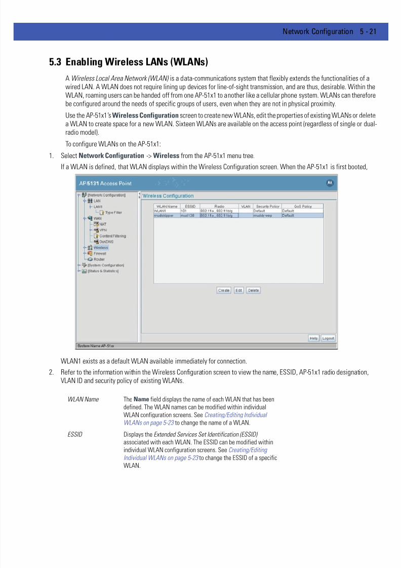
7/18/2019 Motorola AP 5131 Manual
http://slidepdf.com/reader/full/motorola-ap-5131-manual 143/613
Network Configuration 5 - 21
5.3 Enabling Wireless LANs (WLANs)
A Wireless Local Area Network (WLAN) is a data-communications system that flexibly extends the functionalities of awired LAN. A WLAN does not require lining up devices for line-of-sight transmission, and are thus, desirable. Within theWLAN, roaming users can be handed off from one AP-51x1 to another like a cellular phone system. WLANs can thereforebe configured around the needs of specific groups of users, even when they are not in physical proximity.
Use the AP-51x1’s Wireless Configurationscreen to create new WLANs, edit the properties of existing WLANs or deletea WLAN to create space for a new WLAN. Sixteen WLANs are available on the access point (regardless of single or dualradio model).
To configure WLANs on the AP-51x1:
1. Select Network Configuration -> Wireless from the AP-51x1 menu tree.
If a WLAN is defined, that WLAN displays within the Wireless Configuration screen. When the AP-51x1 is first booted,
WLAN1 exists as a default WLAN available immediately for connection.
2. Refer to the information within the Wireless Configuration screen to view the name, ESSID, AP-51x1 radio designation,VLAN ID and security policy of existing WLANs.
WLAN Name The Name field displays the name of each WLAN that has beendefined. The WLAN names can be modified within individual
WLAN configuration screens. See Creating/Editing Individual
WLANs on page 5-23 to change the name of a WLAN.
ESSID Displays the Extended Services Set Identification (ESSID)
associated with each WLAN. The ESSID can be modified within
individual WLAN configuration screens. See Creating/Editing
Individual WLANs on page 5-23 to change the ESSID of a specific
WLAN.

7/18/2019 Motorola AP 5131 Manual
http://slidepdf.com/reader/full/motorola-ap-5131-manual 144/613
5 - 22 WiNG 4.4 AP-5131 Product Reference Guide
3. Click the Create button (if necessary) to launch the New WLAN screen. Use the New WLAN screen to define the propertiesof a new WLAN that would display and be selectable within the Wireless Configuration screen. For additionalinformation, see Creating/Editing Individual WLANs on page 5-23 .
4. Click the Edit button (if necessary) to launch the Edit WLAN screen. Use the Edit WLAN screen to revise the properties ofan existing WLAN that would continue display and be selectable within the Wireless Configuration screen. For additionalinformation, see Creating/Editing Individual WLANs on page 5-23 .
5. Consider using the Delete button to remove an existing WLAN if it has become outdated and is no longer required or if youare coming close the maximum 16 WLANs available per AP-51x1.
6. Click Logout to securely exit the Access Point applet. A prompt displays confirming the logout before the applet is closed.
Radio The Radio field displays the name of the AP-51x1 radio the WLAN
is mapped to (either the 802.11a radio or the 802.11b/g radio). To
change the radio designation for a specific WLAN, see Creating/
Editing Individual WLANs on page 5-23 .
VLAN The VLAN field displays the specific VLAN the target WLAN ismapped to. For information on VLAN configuration for the WLAN,
see Configuring VLAN Support on page 5-4 .
Security Policy The Security Policy field displays the security profile configured
for the target WLAN. For information on configuring security for a
WLAN, see Enabling Authentication and Encryption Schemes on
page 6-5 .
QoS Policy The QoS Policy field displays the quality of service currently
defined for the WLAN. This policy outlines which data types
receive priority for the user base comprising the WLAN. For
information on QoS configuration for the WLAN, see Setting the
WLAN Quality of Service (QoS) Policy on page 5-29 .

7/18/2019 Motorola AP 5131 Manual
http://slidepdf.com/reader/full/motorola-ap-5131-manual 145/613
Network Configuration 5 - 23
5.3.1 Creating/Editing Individual WLANs
If the WLANs displayed within the Wireless Configuration screen do not satisfy your network requirements, you caneither create a new WLAN or edit the properties of an existing WLAN.
Use the New WLAN and Edit WLAN screens as required to create/modify a WLAN. To create a new WLAN or edit theproperties of an existing WLAN:
1. Select Network Configuration -> Wireless from the AP-51x1 menu tree.
The Wireless Configuration screen displays.
2. Click the Create button to configure a new WLAN, or highlight a WLAN and click the Edit button to modify an existingWLAN. Either the New WLAN or Edit WLAN screen displays.
3. Set the parameters in the Configuration field as required for the WLAN.
NOTE Before editing the properties of an existing WLAN, ensure it is not beingused by an AP-51x1 radio, or is a WLAN that is needed in its currentconfiguration. Once updated, the previous configuration is not availableunless saved.

7/18/2019 Motorola AP 5131 Manual
http://slidepdf.com/reader/full/motorola-ap-5131-manual 146/613
5 - 24 WiNG 4.4 AP-5131 Product Reference Guide
ESSID Enter the Extended Services Set Identification (ESSID) associated
with the WLAN. The WLAN name is auto-generated using the
ESSID until changed by the user. The maximum number of
characters that can be used for the ESSID is 32.
Name Define or revise the name for the WLAN. The name should be
logical representation of WLAN coverage area (engineering,
marketing etc.). The maximum number of characters that can be
used for the name is 31.
Available On Use the Available On checkboxes to define whether the WLAN
you are creating or editing is available to clients on either the
802.11a or 802.11b/g radio (or both radios). The Available On
checkbox should only be selected for a mesh WLAN if this target
access point is to be configured as a base bridge or repeater (base
and client bridge) on the radio. If the radio for the WLAN is to be
defined as a client bridge only, the Available On checkbox should
not be selected. For more information on defining a WLAN for
mesh support, see Configuring a WLAN for Mesh Networking
Support on page 9-6 .
Max MUs Use the Max MUs field to define the number of MUs permitted to
interoperate within the new or revised WLAN. The maximum (and
default) is 127. However, each access point can only support a
maximum 127 MUs spanned across its 16 available WLANs. If you
intend to define numerous WLANs, ensure each is using a portion
of the 127 available MUs and the sum of the supported MUs across
all WLANs does not exceed 127.
Enable Client Bridge
Backhaul
Select the Enable Client Bridge Backhaul checkbox to make the
WLAN available in the WLAN drop-down menu within the Radio
Configuration screen. This checkbox can be ignored for WLANsnot supporting mesh networking, to purposely exclude them from
the list of WLANs available in the Radio Configuration page
selected specifically for mesh networking support. Only WLANs
defined for mesh networking support should have this checkbox
selected.
Enable Hotspot Select the Enable Hotspot checkbox to allow this WLAN (whether
it be a new or existing WLAN) to be configured for hotspot support.
Clicking the Configure Hotspot button launches a screen wherein
the parameters of the hotspot can be defined. For information on
configuring a target WLAN for hotspot support, see Configuring
WLAN Hotspot Support on page 5-34 . For an overview of what a
hotspot is and what it can provide your wireless network, see
Hotspot Support on page 1-14 .
CAUTION A WLAN cannot be enabled for both mesh and hotspot support at thesame time. Only one of these two options can be enabled at one time,as the GUI and CLI will prevent both from being enabled.

7/18/2019 Motorola AP 5131 Manual
http://slidepdf.com/reader/full/motorola-ap-5131-manual 147/613
Network Configuration 5 - 25
4. Configure the Security field as required to set the data protection requirements for the WLAN.
5. Configure the Advanced field as required to set MU interoperability permissions, secure beacon transmissions, broadcastESSID acceptance and Quality of Service (QoS) policies.
NOTE If 802.11a is selected as the radio used for the WLAN, the WLAN cannotuse a Kerberos supported security policy.
NOTE A WLAN configured to support Mesh should not have a Kerberos or802.1x EAP security policy defined for it, as these two authenticationschemes are not supported within a Mesh network.
Security Policy Use the scroll down Security Policies menu to select the security
scheme best suited for the new or revised WLAN. Click the Create
button to jump to the New Security Policy screen where a new
policy can be created to suit the needs of the WLAN. For more
information, see Configuring WLAN Security Policies on page 5-26 .MU Access Control Select an ACL policy suiting the WLAN‘s MU introperability
requirements from the drop-down menu. If the existing ACL
policies do not satisfy the requirements of the WLAN, a new ACL
policy can be created by pressing the Create button. For more
information, see Configuring a WLAN Access Control List (ACL) on
page 5-27 .
Kerberos User Name Displays the read-only Kerboros User Name used to associate the
wireless client. This value is the ESSID of the access point.
Kerberos Password Enter a Kerberos password if Kerberos has been selected as the
security scheme from within the Security Policies field. The field
is grayed out if Kerberos has not been selected for the WLAN. Forinformation on configuring Kerberos, see Configuring Kerberos
Authentication on page 6-8 .
Disallow MU to MU
Communication
The MU-MU Disallow feature prohibits MUs from communicating
with each other even if they are on different WLANs, assuming one
of the WLAN’s is configured to disallow MU-MU communication.
Therefore, if an MU’s WLAN is configured for MU-MU disallow, it
will not be able to communicate with any other MUs connected to
this access point.
Use Secure Beacon Select the Use Secure Beacon checkbox to not transmit the
access point’s ESSID. If a hacker tries to find an ESSID via an MU,
the ESSID does not display since the ESSID is not in the beacon.
Motorola Solutions recommends keeping the option enabled to
reduce the likelihood of hacking into the WLAN.
7/18/2019 Motorola AP 5131 Manual
http://slidepdf.com/reader/full/motorola-ap-5131-manual 148/613
5 - 26 WiNG 4.4 AP-5131 Product Reference Guide
6. Click Apply to save any changes to the WLAN screen. Navigating away from the screen without clicking Apply results in allchanges to the screens being lost.
7. Click Cancel to securely exit the New WLAN or Edit WLAN screen and return to the Wireless Configuration screen.
5.3.1.1 Configuring WLAN Security Policies
As WLANs are being defined for an AP-51x1, a security policy can be created or an existing policy edited (using the Create or Edit buttons within the Security Configuration screen) to best serve the security requirements of the WLAN. Oncenew policies are defined, they are available within the New WLAN or Edit WLAN screens and can be mapped to anyWLAN. A single security policy can be used by more than one WLAN if its logical to do so. For example, there may be twoor more WLANs within close proximity of each other requiring the same data protection scheme.
To create a new security policy or modify an existing policy:
1. Select Network Configuration -> Wireless -> Security from the AP-51x1 menu tree.
The Security Configuration screen appears with existing policies and their attributes displayed.
Accept Broadcast
ESSID
Select the Accept Broadcast ESSID checkbox to associate an
MU that has a blank ESSID (regardless of which ESSID the access
point is currently using). Sites with heightened security
requirements may want to leave the checkbox unselected and
configure each MU with an ESSID. The default is unselected, thus
not allowing the acceptance of broadcast ESSIDs.
Quality of Service
Policy
If QoS policies are undefined (none), select the Create button to
launch the New QoS Policy screen. Use this screen to create a
QoS policy, wherein data traffic for the new or revised WLAN can
be prioritized to best suit the MU transmissions within that WLAN.
For more information, see Setting the WLAN Quality of Service
(QoS) Policy on page 5-29 .
CAUTION When using the access point’s hotspot functionality, ensure MUs arere-authenticated when changes are made to the characteristics of ahotspot enabled WLAN, as MUs within the WLAN will be dropped
from device association.
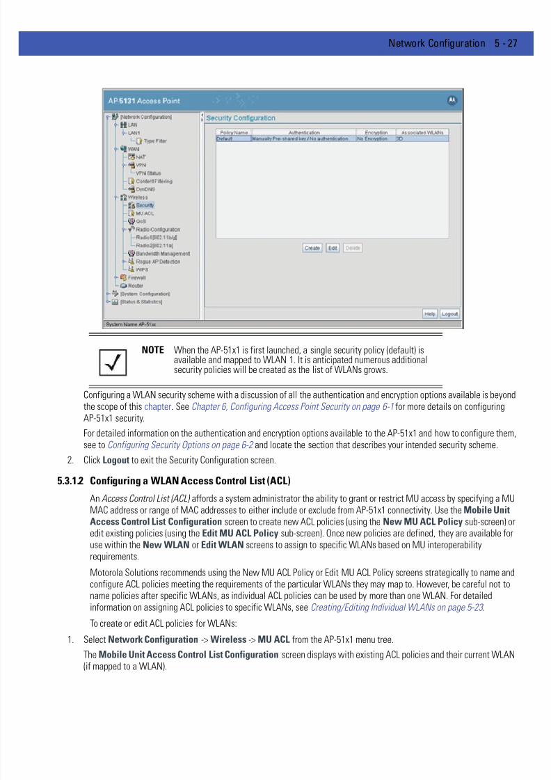
7/18/2019 Motorola AP 5131 Manual
http://slidepdf.com/reader/full/motorola-ap-5131-manual 149/613
Network Configuration 5 - 27
Configuring a WLAN security scheme with a discussion of all the authentication and encryption options available is beyond
the scope of this chapter. See Chapter 6, Configuring Access Point Security on page 6-1 for more details on configuringAP-51x1 security.
For detailed information on the authentication and encryption options available to the AP-51x1 and how to configure them,see to Configuring Security Options on page 6-2 and locate the section that describes your intended security scheme.
2. Click Logout to exit the Security Configuration screen.
5.3.1.2 Configuring a WLAN Access Control List (ACL)
An Access Control List (ACL) affords a system administrator the ability to grant or restrict MU access by specifying a MUMAC address or range of MAC addresses to either include or exclude from AP-51x1 connectivity. Use the Mobile UnitAccess Control List Configuration screen to create new ACL policies (using the New MU ACL Policy sub-screen) oredit existing policies (using the Edit MU ACL Policy sub-screen). Once new policies are defined, they are available for
use within the New WLAN or Edit WLAN screens to assign to specific WLANs based on MU interoperabilityrequirements.
Motorola Solutions recommends using the New MU ACL Policy or Edit MU ACL Policy screens strategically to name andconfigure ACL policies meeting the requirements of the particular WLANs they may map to. However, be careful not toname policies after specific WLANs, as individual ACL policies can be used by more than one WLAN. For detailedinformation on assigning ACL policies to specific WLANs, see Creating/Editing Individual WLANs on page 5-23 .
To create or edit ACL policies for WLANs:
1. Select Network Configuration -> Wireless -> MU ACL from the AP-51x1 menu tree.
The Mobile Unit Access Control List Configuration screen displays with existing ACL policies and their current WLAN(if mapped to a WLAN).
NOTE When the AP-51x1 is first launched, a single security policy (default) isavailable and mapped to WLAN 1. It is anticipated numerous additionalsecurity policies will be created as the list of WLANs grows.

7/18/2019 Motorola AP 5131 Manual
http://slidepdf.com/reader/full/motorola-ap-5131-manual 150/613
5 - 28 WiNG 4.4 AP-5131 Product Reference Guide
2. Click the Create button to configure a new ACL policy, or select a policy and click the Edit button to modify an existing ACL
policy. The access point supports a maximum of 16 MU ACL policies.
Either the New MU ACL Policy or Edit MU ACL Policy screens display.
NOTE When the AP-51x1 is first launched, a single ACL policy (default) isavailable and mapped to WLAN 1. It is anticipated numerous additionalACL policies will be created as the list of WLANs grows.
7/18/2019 Motorola AP 5131 Manual
http://slidepdf.com/reader/full/motorola-ap-5131-manual 151/613
Network Configuration 5 - 29
3. Assign a name to the new or edited ACL policy that represents an inclusion or exclusion policy specific to a particular typeof MU traffic you may want to use with a single or group of WLANs. More than one WLAN can use the same ACL policy.
4. Configure the parameters within the Mobile Unit Access Control List field to allow or deny MU access to the AP-51x1.
The MU adoption list identifies MUs by their MAC address. The MAC address is the MU's unique Media Access Control
number printed on the device (for example, 00:09:5B:45:9B:07) by the manufacturer. A maximum of 200 MU MAC addressescan be added to the New/Edit MU ACL Policy screen.
5. Click Apply to save any changes to the New MU ACL Policy or Edit MU ACL Policy screen and return to the Mobile UnitAccess Control List Configuration screen. Navigating away from the screen without clicking Apply results in changes to thescreens being lost.
6. Click Cancel to securely exit the New MU ACL Policy or Edit MU ACL Policy screen and return to the Mobile Unit AccessControl List Configuration screen.
7. Click Logout within the Mobile Unit Access Control List Configuration screen to securely exit the Access Point applet. Aprompt displays confirming the logout before the applet is closed.
5.3.1.3 Setting the WLAN Quality of Service (QoS) Policy
The AP-51x1 can keep a list of QoS policies that can be used from the New WLAN or Edit WLAN screens to map toindividual WLANs. Use the Quality of Service Configuration screen to configure WMM policies that can improve theuser experience for audio, video and voice applications by shortening the time between packet transmissions for higherpriority (multimedia) traffic.
Use the Quality of Service Configuration screen to define the QoS policies for advanced network traffic managementand multimedia applications support. If the existing QoS policies are insufficient, a new policy can be created or an existingpolicy can be modified using the New QoS Policy or Edit QoS Policy screens. Once new policies are defined, they areavailable for use within the New WLAN or Edit WLAN screens to assign to specific WLANs based on MUinteroperability requirements.
Motorola Solutions recommends using the New QoS Policy and Edit QoS Policy screens strategically to name andconfigure QoS policies meeting the requirements of the particular WLANs they may to. However, be careful not to namepolicies after specific WLANs, as individual QoS policies can be used by more than one WLAN. For detailed informationon assigning QoS policies to specific WLANs, seeCreating/Editing Individual WLANs on page 5-23 .
To configure QoS policies:
1. Select Network Configuration -> Wireless -> QoS from the AP-51x1 menu tree.
The Quality of Service Configuration screen displays with existing QoS policies and their current WLAN (if mapped to aWLAN).
Access for the listed
Mobile Units
Use the drop-down list to select Allow or Deny. This rule applies
to the MUs listed in the table. For example, if the adoption rule is
to Allow, access is granted for all MUs except those listed in the
table.
Add Click the Add button to create a new entry using only the StartMAC column to specify a MAC address, or uses both the StartMAC and End MAC columns to specify a range of MAC addresses.
Delete Click the Delete button to remove a selected list entry.

7/18/2019 Motorola AP 5131 Manual
http://slidepdf.com/reader/full/motorola-ap-5131-manual 152/613
5 - 30 WiNG 4.4 AP-5131 Product Reference Guide
2. Click the Create button to configure a new QoS policy, or select a policy and click the Edit button to modify an existing QoSpolicy. The access point supports a maximum of 16 QoS policies.
NOTE When the AP-51x1 is first launched, a single QoS policy (default) isavailable and mapped to WLAN 1. It is anticipated additional QoS policieswill be created as the list of WLANs grows.
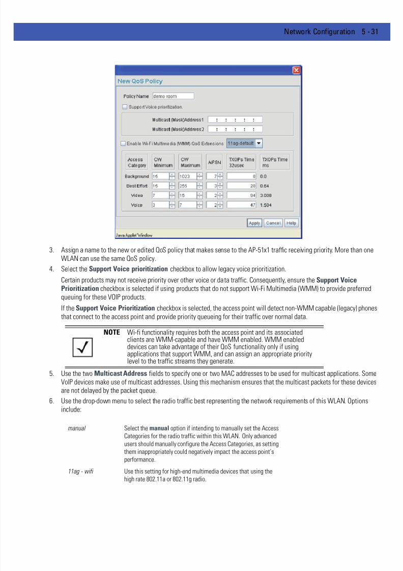
7/18/2019 Motorola AP 5131 Manual
http://slidepdf.com/reader/full/motorola-ap-5131-manual 153/613
Network Configuration 5 - 31
3. Assign a name to the new or edited QoS policy that makes sense to the AP-51x1 traffic receiving priority. More than oneWLAN can use the same QoS policy.
4. Select the Support Voice prioritization checkbox to allow legacy voice prioritization.
Certain products may not receive priority over other voice or data traffic. Consequently, ensure the Support VoicePrioritization checkbox is selected if using products that do not support Wi-Fi Multimedia (WMM) to provide preferred
queuing for these VOIP products.If the Support Voice Prioritization checkbox is selected, the access point will detect non-WMM capable (legacy) phonesthat connect to the access point and provide priority queueing for their traffic over normal data.
5. Use the two Multicast Address fields to specify one or two MAC addresses to be used for multicast applications. SomeVoIP devices make use of multicast addresses. Using this mechanism ensures that the multicast packets for these devicesare not delayed by the packet queue.
6. Use the drop-down menu to select the radio traffic best representing the network requirements of this WLAN. Optionsinclude:
NOTE Wi-fi functionality requires both the access point and its associatedclients are WMM-capable and have WMM enabled. WMM enableddevices can take advantage of their QoS functionality only if usingapplications that support WMM, and can assign an appropriate prioritylevel to the traffic streams they generate.
manual Select the manual option if intending to manually set the Access
Categories for the radio traffic within this WLAN. Only advanced
users should manually configure the Access Categories, as setting
them inappropriately could negatively impact the access point’s
performance.
11ag - wifi Use this setting for high-end multimedia devices that using the
high rate 802.11a or 802.11g radio.

7/18/2019 Motorola AP 5131 Manual
http://slidepdf.com/reader/full/motorola-ap-5131-manual 154/613
5 - 32 WiNG 4.4 AP-5131 Product Reference Guide
7. Select the Enable Wi-Fi Multimedia (WMM) QoS Extensions checkbox to configure the AP-51x1’s QoS AccessCategories. The Access Categories are not configurable unless the checkbox is selected. Access Categories include:
8. Configure the CW min and CW max (contention windows), AIFSN (Arbitrary Inter-Frame Space Number ) and TXOPs Time (opportunity to transmit) for each Access Category. Their values are explained as follows.
11b - wifi Use this setting for high-end devices multimedia devices that use
the 802.11b radio.
11ag - default Use this setting for typical “data-centric” MU traffic over the high
rate 802.11a or 802.11g radio.
11b - default Use this setting for typical “data-centric” MU traffic over the802.11b radio.
11ag voice Use this setting for “Voice-Over-IP” traffic over the high rate
802.11a or 802.11g radio.
11b voice Use this setting for “Voice-Over-IP” traffic over the 802.11b radio.
CAUTION Motorola Solutions recommends using the drop-down menu to definethe intended radio traffic within the WLAN. Once an option isselected, you do not need to adjust the values for the AccessCategories, unless qualified to do so. Changing the Access Categorydefault values could negatively impact the performance of the access
point.
Background Backgrounds traffic is typically of a low priority (file transfers, print
jobs ect.). Background traffic typically does not have strict latency
(arrival) and throughput requirements.
Best Effort Best Effort traffic includes traffic from legacy devices or
applications lacking QoS capabilities. Best Effort traffic is
negatively impacted by data transfers with long delays as well as
multimedia traffic.
Video Video traffic includes music streaming and application trafficrequiring priority over all other types of network traffic.
Voice Voice traffic includes VoIP traffic and typically receives priority over
Background and Best Effort traffic.
CW Min The contention window minimum value is the least amount of time
the MU waits before transmitting when there is no other data
traffic on the network. The longer the interval, the lesser likelihood
of collision. This value should be set to a smaller increment for
higher priority traffic. Reduce the value when traffic on the WLANis anticipated as being smaller.
CW Max The contention window maximum value is the maximum amount of
time the MU waits before transmitting when there is no other data
traffic on the network. The longer the interval, the lesser likelihood
of collision, but the greater propensity for longer transmit periods.
AIFSN The AIFSN is the minimum interframe space between data packets
transmitted for the selected Access Category. This value should be
set to a smaller increment for higher priority traffic to reduce
packet delay time.

7/18/2019 Motorola AP 5131 Manual
http://slidepdf.com/reader/full/motorola-ap-5131-manual 155/613
Network Configuration 5 - 33
9. Click Apply to save any changes to the New QoS Policy or Edit QoS Policy screen to return to the Quality of ServiceConfiguration screen. Navigating away from the screen without clicking Apply results in all changes to the screens beinglost.
10. Click Cancel to securely exit the New QoS Policy or Edit QoS Policy screen and return to the Quality of Service Configurationscreen.
11. Click Logout within the Quality of Service Configuration screen to securely exit the Access Point applet. A prompt displaysconfirming the logout before the applet is closed.
5.3.1.3.1 U-APSD (WMM Power Save) Support
The access point now supports Unscheduled Automatic Power Save Delivery (U-APSD), often referred to as WMM PowerSave. U-APSD provides a periodic frame exchange between a voice capable MU and the access point during a VoIP call,while legacy power management is still utilized for typical data frame exchanges. The access point and its associated MUactivate the new U-APSD power save approach when a VoIP traffic stream is detected. The MU then buffers frames fromthe voice traffic stream and sends a VoIP frame with an implicit "poll" request to its associated access point. The accesspoint responds to the poll request with buffered VoIP stream frame(s). When a voice-enabled MU wakes up at a designatedVoIP frame interval, it sends a VoIP frame with an implicit "poll" request to its associated access point. The access pointresponds to the poll request with buffered VoIP stream frame(s).
TXOPs Time 32usec The TXOPs Time is the interval the transmitting MU is assigned
for transmitting. The default for Background traffic is 0. The same
TXOPs values should be used for either the 802.11a or 802.11b/g
radio, there is no difference.
TXOPs Time ms TXOP times range from 0.2 ms (background priority) to 3 ms (videopriority) in a 802.11a network, and from 1.2 ms to 6 ms in an
802.11b/g network. The TXOP bursting capability greatly enhances
the efficiency for high data rate traffic such as streaming video
NOTE The access point ships with the U-APSD feature disabled by default. It isautomatically enabled when WMM is enabled for a WLAN. Thus, U-APSDis only functional when WMM is enabled. If WMM is disabled, thenU-APSD is disabled as well.

7/18/2019 Motorola AP 5131 Manual
http://slidepdf.com/reader/full/motorola-ap-5131-manual 156/613
5 - 34 WiNG 4.4 AP-5131 Product Reference Guide
5.3.1.4 Configuring WLAN Hotspot Support
The access point enables hotspot operators to provide user authentication and accounting without a special clientapplication. The access point uses a traditional Internet browser as a secure authentication device. Rather than rely onbuilt-in 802.11security features to control access point association privileges, configure a WLAN with no WEP (an open
network). The access point issues an IP address to the user using a DHCP server, authenticates the user and grants theuser to access the Internet.
When a user visits a public hotspot and wants to browse to a Web page, they boot up their laptop and associate with thelocal Wi-Fi network by entering the correct SSID. They then start a browser. The hotspot access controller forces this un-authenticated user to a Welcome page from the hotspot Operator that allows the user to login with a username andpassword.
The access point hotspot functionality requires the following:
• HTTP Redirection - Redirects unauthenticated users to a specific page specified by the Hotspot provider.
• User authentication - Authenticates users using a Radius server.
• Walled garden support - Enables a list of IP address (not domain names) accessed without authentication.
• Billing system integration - Sends accounting records to a Radius accounting server.
To configure hotspot functionality for an access point WLAN:
1. Ensure the Enable Hotspot checkbox is selected from within the target WLAN screen, and ensure the WLAN is properlyconfigured.
Any of the sixteen WLANs on the access point can be configured as a hotspot. For hotspot enabled WLANs, DHCP, DNS,HTTP
and HTTP-S traffic is allowed (before you login to the hotspot), while TCP/IP packets are redirected to the port on the subnetto which the WLAN is mapped. For WLANs not hotspot-enabled, all packets are allowed.
2. Click the Configure Hotspot button within the WLAN screen to display the Hotspot Configuration screen for that targetWLAN.
CAUTION When using the access point’s hotspot functionality, ensure MUs arere-authenticated when changes are made to the characteristics of ahotspot enabled WLAN, as MUs within the WLAN will be droppedfrom access point device association.
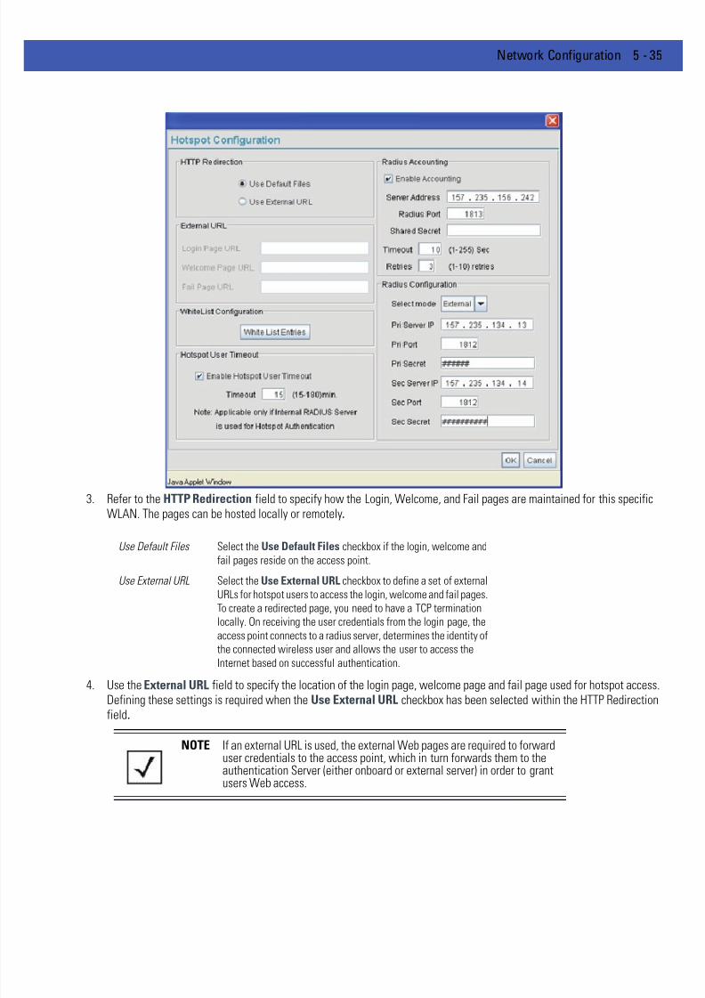
7/18/2019 Motorola AP 5131 Manual
http://slidepdf.com/reader/full/motorola-ap-5131-manual 157/613
Network Configuration 5 - 35
3. Refer to the HTTP Redirection field to specify how the Login, Welcome, and Fail pages are maintained for this specificWLAN. The pages can be hosted locally or remotely.
.
4. Use the External URL field to specify the location of the login page, welcome page and fail page used for hotspot access.
Defining these settings is required when the Use External URL checkbox has been selected within the HTTP Redirectionfield.
Use Default Files Select the Use Default Files checkbox if the login, welcome and
fail pages reside on the access point.
Use External URL Select the Use External URL checkbox to define a set of external
URLs for hotspot users to access the login, welcome and fail pages.
To create a redirected page, you need to have a TCP termination
locally. On receiving the user credentials from the login page, the
access point connects to a radius server, determines the identity of
the connected wireless user and allows the user to access the
Internet based on successful authentication.
NOTE If an external URL is used, the external Web pages are required to forwarduser credentials to the access point, which in turn forwards them to theauthentication Server (either onboard or external server) in order to grantusers Web access.
7/18/2019 Motorola AP 5131 Manual
http://slidepdf.com/reader/full/motorola-ap-5131-manual 158/613
5 - 36 WiNG 4.4 AP-5131 Product Reference Guide
5. Select the Enable Hotspot User Timeout checkbox to define a timeout interval forcing users (when exceeded) to re-establish their login credentials to continue using the access point supported hotspot.
Leaving the checkbox unselected is not recommended unless you plan to provide unlimited hotspot support to users.
If this option is selected, enter an interval (between 15 and 180 minutes). When the provided interval is exceeded, the user
is logged out of their hotspot session and forced to login to the hotspot again to access to the hotspot supported WLAN. Thedefault timeout interval is 15 minutes.
6. Click the White List Entries button (within the WhiteList Configuration field) to create a set of allowed destination IPaddresses. These allowed destination IP addresses are called a White List. Ten configurable IP addresses are allowed foreach WLAN. For more information, see Defining the Hotspot White List on page 5-37 .
7. Refer to the Radius Accounting field to enable Radius accounting and specify the a timeout and retry value for the Radiusserver.
Login Page URL Define the complete URL for the location of the Login page. The
Login screen will prompt the hotspot user for a username and
password to access the Welcome page.
Welcome Page URL Define the complete URL for the location of the Welcome page. TheWelcome page asserts the hotspot user has logged in successfully
and can access the Internet.
Fail Page URL Define the complete URL for the location of the Fail page. The Fail
screen asserts the hotspot authentication attempt failed, you are
not allowed to access the Internet and you need to provide correct
login information to access the Internet.
NOTE The Enable Hotspot User Timeout option is only available if using theaccess point’s internal Radius Server for user authentication.
NOTE If using an external Web Server over the WAN port, and the hotspot’sHTTP pages (login or welcome) redirect to the access point’s WAN IPaddress for CGI scripts, the IP address of the external Web server and theaccess point’s WAN IP address should be entered in the White List.
Enable Accounting Select the Enable Accounting checkbox to enable a Radius
Accounting Server used for Radius authentication for a target
hotspot user.
Server Address Specify an IP address for the external Radius Accounting server
used to provide Radius accounting for the hotspot. If using thisoption, an internal Radius server cannot be used. The IP address of
the internal Radius server is fixed at 127.0.0.1 and cannot be used
for the external Radius server.
Radius Port Specify the port on which the Radius accounting server is listening.
Shared Secret Specify a shared secret for accounting authentication for the
hotspot. The shared secret is required to match the shared secret
on the external Radius accounting server.

7/18/2019 Motorola AP 5131 Manual
http://slidepdf.com/reader/full/motorola-ap-5131-manual 159/613
Network Configuration 5 - 37
8. Refer to the Radius Configuration field to define a primary and secondary Radius server port and shared secret password
9. Click OK to save any changes to the Hotspot Configuration screen. Navigating away from the screen without clicking Applyresults in all changes to the screens being lost.
10. Click Cancel (if necessary) to undo any changes made. Cancel reverts the settings displayed on the Hotspot Configurationscreen to the last saved configuration.
5.3.1.4.2 Defining the Hotspot White List
To host a Login, Welcome or Fail page on the external Web server, the IP address of that Web server should be in accesspoint’s White List.
Timeout Set the timeout value in seconds (1-255) used to timeout users
accessing the Radius Accounting server if they have not
successfully accessed the Accounting Server.
Retries Define the number of retries (1-10) the user is allowed to access
the Radius Accounting Server if the first attempt fails. The defaultis 1.
Select mode Use the Select mode drop-down menu to define whether an
Internal or External server is to be used for the primary server.
Pri Server IP Define the IP address of the primary Radius server. This is the
address of your first choice for Radius server.
Pri Port Enter the TCP/IP port number for the server acting as the primary
Radius server. The default port is 1812.
Pri Secret Enter the shared secret password used with the primary RadiusServer.
Sec Server IP Define the IP address of the secondary Radius server. This is the
address of your second choice for Radius server.
Sec Port Enter the TCP/IP port number for the server acting as the secondary
Radius server. The default port is 1812.
Sec Secret Enter the shared secret password used with the secondary Radius
Server.
NOTE If using an external Web Server over the WAN port, and the hotspot’sHTTP pages (login or welcome) redirect to the access point’s WAN IPaddress for CGI scripts, the IP address of the external Web server and theaccess point’s WAN IP address should be entered in the White List.
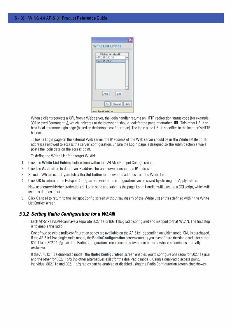
7/18/2019 Motorola AP 5131 Manual
http://slidepdf.com/reader/full/motorola-ap-5131-manual 160/613
5 - 38 WiNG 4.4 AP-5131 Product Reference Guide
When a client requests a URL from a Web server, the login handler returns an HTTP redirection status code (for example,301 Moved Permanently), which indicates to the browser it should look for the page at another URL. This other URL canbe a local or remote login page (based on the hotspot configuration). The login page URL is specified in the location’s HTTPheader.
To host a Login page on the external Web server, the IP address of the Web server should be in the White list (list of IPaddresses allowed to access the server) configuration. Ensure the Login page is designed so the submit action alwaysposts the login data on the access point.
To define the White List for a target WLAN:
1. Click the White List Entries button from within the WLAN’s Hotspot Config screen.
2. Click the Add button to define an IP address for an allowed destination IP address.
3. Select a White List entry and click the Del button to remove the address from the White List.
4. Click OK to return to the Hotspot Config screen where the configuration can be saved by clicking the Apply button.
Now user enters his/her credentials on Login page and submits the page. Login Handler will execute a CGI script, which willuse this data as input.
5. Click Cancel to return to the Hotspot Config screen without saving any of the White List entries defined within the WhiteList Entries screen.
5.3.2 Setting Radio Configuration for a WLAN
Each AP-51x1 WLAN can have a separate 802.11a or 802.11b/g radio configured and mapped to that WLAN. The first stepis to enable the radio.
One of two possible radio configuration pages are available on the AP-51x1 depending on which model SKU is purchased.If the AP-51x1 is a single-radio model, the Radio Configuration screen enables you to configure the single radio for either802.11a or 802.11b/g use. The Radio Configuration screen contains two radio buttons whose selection is mutuallyexclusive.
If the AP-51x1 is a dual-radio model, the Radio Configuration screen enables you to configure one radio for 802.11a useand the other for 802.11b/g (no other alternatives exist for the dual-radio model). Using a dual-radio access point,individual 802.11a and 802.11b/g radios can be enabled or disabled using the Radio Configuration screen checkboxes.
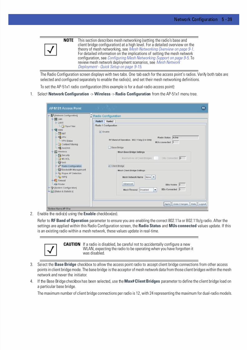
7/18/2019 Motorola AP 5131 Manual
http://slidepdf.com/reader/full/motorola-ap-5131-manual 161/613
Network Configuration 5 - 39
The Radio Configuration screen displays with two tabs. One tab each for the access point’s radios. Verify both tabs areselected and configured separately to enable the radio(s), and set their mesh networking definitions.
To set the AP-51x1 radio configuration (this example is for a dual-radio access point):
1. Select Network Configuration -> Wireless -> Radio Configuration from the AP-51x1 menu tree.
2. Enable the radio(s) using the Enable checkbox(es).
Refer to RF Band of Operation parameter to ensure you are enabling the correct 802.11a or 802.11b/g radio. After thesettings are applied within this Radio Configuration screen, the Radio Status and MUs connected values update. If thisis an existing radio within a mesh network, these values update in real-time.
3. Select the Base Bridge checkbox to allow the access point radio to accept client bridge connections from other accesspoints in client bridge mode. The base bridge is the acceptor of mesh network data from those client bridges within the meshnetwork and never the initiator.
4. If the Base Bridge checkbox has been selected, use the Max# Client Bridges parameter to define the client bridge load ona particular base bridge.
The maximum number of client bridge connections per radio is 12, with 24 representing the maximum for dual-radio models
NOTE This section describes mesh networking (setting the radio’s base andclient bridge configuration) at a high level. For a detailed overview on the theory of mesh networking, see Mesh Networking Overview on page 9-1.For detailed information on the implications of setting the mesh networkconfiguration, see Configuring Mesh Networking Support on page 9-5 . Toreview mesh network deployment scenarios, see Mesh NetworkDeployment - Quick Setup on page 9-15 .
CAUTION If a radio is disabled, be careful not to accidentally configure a newWLAN, expecting the radio to be operating when you have forgotten itwas disabled.
7/18/2019 Motorola AP 5131 Manual
http://slidepdf.com/reader/full/motorola-ap-5131-manual 162/613
5 - 40 WiNG 4.4 AP-5131 Product Reference Guide
Once the settings within the Radio Configuration screen are applied (for an initial deployment), the current number of clientbridge connections for this specific radio displays within the CBs Connected field. If this is an existing radio within a meshnetwork, this value updates in real-time.
5. Select the Client Bridge checkbox to enable the access point radio to initiate client bridge connections with other meshnetwork supported access point’s using the same WLAN.
If the Client Bridge checkbox has been selected, use theMesh Network Name
drop-down menu to select the WLAN (ESS)the client bridge uses to establish a wireless link. The default setting, is (WLAN1). Motorola Solutions recommends creating(and naming) a WLAN specifically for mesh networking support to differentiate the Mesh supported WLAN from non-Meshsupported WLANs.
Once the settings within the Radio Configuration screen are applied (for an initial deployment), the current number of basebridges visible to the radio displays within the BBs Visible field, and the number of base bridges currently connected tothe radio displays within the BBs Connected field. If this is an existing radio within a mesh network, these values updatein real-time.
6. Click the Advanced button to define a prioritized list of access points to define Mesh Connection links. For a detailedoverview on mesh networking and how to configure the radio for mesh networking support, see Configuring MeshNetworking Support on page 9-5 .
7. If using a dual-radio model access point, refer to the Mesh Timeout drop-down menu to define whether one of the radio’sbeacons on an existing WLAN or if a client bridge radio uses an uplink connection. The Mesh Timeout value is not available
on a single-radio access point, since the radio would have to stop beaconing and go into scan mode to determine if a basebridge uplink is lost. The following drop-down menu options are available:
CAUTION An access point is Base Bridge mode logs out whenever a ClientBridge associates to the Base Bridge over the LAN connection. Thisproblem is not experienced over the access point’s WAN connection. Ifthis situation is experienced, log-in to the access point again.
CAUTION A problem could arise if a Base Bridge’s Indoor channel is notavailable on an Outdoor Client Bridge's list of available channels. Aslong as an Outdoor Client Bridge has the Indoor Base Bridge channelin its available list of channels, it can associate to the Base Bridge.
CAUTION An access point in client bridge mode cannot use a WLAN configuredwith a Kerberos or EAP 802.1x based security scheme, as theseauthentication types secure user credentials not the mesh networkitself.
NOTE Ensure you have verified the radio configuration for both Radio 1 andRadio 2 before saving the existing settings and exiting the Radio
Configuration screen.

7/18/2019 Motorola AP 5131 Manual
http://slidepdf.com/reader/full/motorola-ap-5131-manual 163/613
Network Configuration 5 - 41
For a detailed overview on mesh networking and how to configure the radio for mesh networking support, see ConfiguringMesh Networking Support on page 9-5 .
8. The Client Bridge Signal Monitor feature continuously monitors the connection between the AP and the Base Bridge to which
it is mesh connected to. When the signal strength of the Base Bridge falls below a configured threshold, the AP starts aperiodic monitoring of the Base Bridge’s signal strength for 60 seconds. This monitoring is abandoned if the signal strengthbecomes more than the configured threshold during the period of monitoring. When this happens, the monitoring period isreset back to 60 seconds. While this monitoring happens, the AP also passively listens to and monitors the signal strengthof the other Base Bridges.
If, at the end of 60 seconds, the Base Bridge’s signal strength remains below the configured threshold, the AP compares thesignal strength of the existing Base Bridge with the signal strength of each of the found Base Bridges. All Base Bridges withsignal strength below the signal strength of the connected Base Bridge are ignored. Of the remaining Base Bridges, if thedifference in signal strength is greater than the configured delta value, the connection to the existing Base Bridge is droppedand a new Base Bridge is selected based on the highest RSSI value. If the difference in signal strength is less than theconfigured delta value, the existing connection is maintained.
Click the Client Bridge Signal Monitor to enable the device to monitor the signal strength of the base bridge it isconnected to.
Enter a value in the Client Bridge Signal Threshold field. This configures the signal strength of the base bridge belowwhich the device keeps monitoring the connection to the base bridge. The default value is 65 dbm.
Enter a value in the Client Bridge Signal Delta field. This is the difference between the signal strength of the monitoredbase bridge and the found base bridges that causes the AP to drop its existing Base Bridge and establish a connection to anew Base Bridge.
9. Click Apply to save any changes to the Radio Configuration screen. Navigating away from the screen without clicking Applyresults in all changes to the screens being lost.
Disabled When disabled, both radios are up at boot time and beaconing. If
one radio (radio 1) does not have a mesh connection, the other
radio (radio 2) is not affected. Radio 2 continues to beacon and
associate MUs, but MU's can only communicate amongst
themselves using the access point. Disabled is the default value.
Uplink Detect When Uplink Detect is selected, the access point only boots up the
radio configured as a client bridge. The access point boots up the
second radio as soon as the first mesh connection is established.
However, if the client bridge radio loses its uplink connection, the
second radio shuts down immediately. Uplink detect is the
recommended setting within a multi-hop mesh network.
Enabled If the mesh connection is down on one radio (radio 1), the other
radio (radio 2) is brought down and stops beaconing after the
timeout period (45 - 65535 seconds). This allows the client bridge
(radio 1) to roam without dropping the MU's associated to radio 2.
The disadvantage is that radio 2 may beacon for the timeout period
and have to drop associated MU's because radio 1 could not
establish its uplink. The default timeout period is 45 seconds.
NOTE The Mesh Time Out variable overrides the Ethernet Port Time Out (EPTO)setting on the LAN page when the access point is in bridge mode. As longas the mesh is down, the access point acts in accordance to the MeshTime Out setting regardless of the state of the Ethernet. However, if theEthernet goes down and the mesh link is still up, the EPTO takes effect.
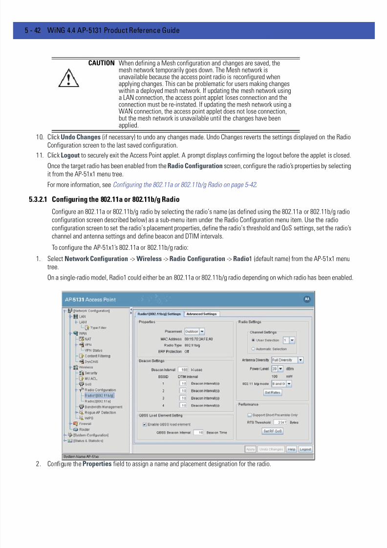
7/18/2019 Motorola AP 5131 Manual
http://slidepdf.com/reader/full/motorola-ap-5131-manual 164/613
5 - 42 WiNG 4.4 AP-5131 Product Reference Guide
10. Click Undo Changes (if necessary) to undo any changes made. Undo Changes reverts the settings displayed on the RadioConfiguration screen to the last saved configuration.
11. Click Logout to securely exit the Access Point applet. A prompt displays confirming the logout before the applet is closed.
Once the target radio has been enabled from the Radio Configuration screen, configure the radio’s properties by selectingit from the AP-51x1 menu tree.
For more information, see Configuring the 802.11a or 802.11b/g Radio on page 5-42 .
5.3.2.1 Configuring the 802.11a or 802.11b/g Radio
Configure an 802.11a or 802.11b/g radio by selecting the radio’s name (as defined using the 802.11a or 802.11b/g radioconfiguration screen described below) as a sub-menu item under the Radio Configuration menu item. Use the radioconfiguration screen to set the radio’s placement properties, define the radio’s threshold and QoS settings, set the radio’schannel and antenna settings and define beacon and DTIM intervals.
To configure the AP-51x1’s 802.11a or 802.11b/g radio:
1. Select Network Configuration -> Wireless -> Radio Configuration -> Radio1 (default name) from the AP-51x1 menutree.
On a single-radio model, Radio1 could either be an 802.11a or 802.11b/g radio depending on which radio has been enabled.
2. Configure the Properties field to assign a name and placement designation for the radio.
CAUTION When defining a Mesh configuration and changes are saved, themesh network temporarily goes down. The Mesh network isunavailable because the access point radio is reconfigured whenapplying changes. This can be problematic for users making changeswithin a deployed mesh network. If updating the mesh network usinga LAN connection, the access point applet loses connection and theconnection must be re-instated. If updating the mesh network using aWAN connection, the access point applet does not lose connection,but the mesh network is unavailable until the changes have beenapplied.

7/18/2019 Motorola AP 5131 Manual
http://slidepdf.com/reader/full/motorola-ap-5131-manual 165/613
Network Configuration 5 - 43
3. Configure the Radio Settings field to assign a channel, antenna diversity setting, radio transmit power level and data rate
Placement Use the Placement drop-down menu to specify whether the radio
is located outdoors or indoors. Default placement depends on the
country of operation selected for the AP-51x1.
MAC Address The AP-51x1, like other Ethernet devices, has a unique, hardwareencoded Media Access Control (MAC) or IEEE address. MAC
addresses determine the device sending or receiving data. A MAC
address is a 48-bit number written as six hexadecimal bytes
separated by colons. For example: 00:A0:F8:24:9A:C8. For
additional information on access point MAC address assignments,
see AP-51xx MAC Address Assignment on page 1-19 .
Radio Type The Radio Type parameter simply displays the radio type as
802.11a or 802.11b/g. This field is read only and always displays
the radio type selected from the AP-51x1 menu tree under the
Radio Configuration item.
ERP Protection Extended Rate PHY (ERP) allows 802.11g MUs to interoperate with
802.11b only MUs. ERP Protection is managed automatically by theaccess point and informs users when 802.11b MUs are present
within the access point’s coverage area. The presence of 802.11b
MUs within the 802.11g coverage area negatively impacts network
performance, so this feature should looked to as an indicator of
why network performance has been degraded.
Channel Setting The following channel setting options exist:
User Selection - If selected, use the drop-down menu to specify
the legal channel for the intended country of operation. The drop-
down menu is not available if this option is not selected.
Automatic Selection - When the access point is booted, theaccess point scans non-overlapping channels listening for beacons
from other access points. For 802.11b, it scans channels 1, 6, and
11. For 802.11a, all channels are non-overlapping. After the
channels are scanned, it will select the channel with the fewest
access points. In the case of multiple access points on the same
channel, it will select the channel with the lowest average power
level.
The Uniform Spreading option is available (and is the default
setting for the 802.11a radio). To comply with Dynamic Frequency
Selection (DFS) requirements in the European Union, the 802.11a
radio uses a randomly selected channel each time the access point
is powered on.Antenna Diversity Specifies the antenna selection for the 802.11a radio. Options
include Primary Only, Secondary Only and Full Diversity . The default
setting is Primary. However, Diversity can improve performance
and signal reception in areas where interference is significant and
is recommended when two antennas are supported.
Power Level Defines the transmit power of the 802.11a or 802.11b/g antenna(s).
The values are expressed in dBm and mW.

7/18/2019 Motorola AP 5131 Manual
http://slidepdf.com/reader/full/motorola-ap-5131-manual 166/613
5 - 44 WiNG 4.4 AP-5131 Product Reference Guide
4. Refer to the Beacon Settings field to set the radio beacon and DTIM intervals.
802.11 b/g mode Specify b only, g only or b and g to define whether the 802.11b/
g radio transmits in the 2.4 Ghz band exclusively for 802.11b
(legacy) clients or transmits in the 2.4 Ghz band for 802.11g clients.
Selecting b and g enables the AP-51x1 to transmit to both b and g
clients if legacy clients (802.11b) partially comprise the network.
Select accordingly based on the MU requirements of the network.This parameter does not apply to AP-51x1 802.11a radios.
Set Rates Click the Set Rates button to display a window for selecting
minimum and maximum data transmit rates for the radio. At least
one Basic Rate must be selected as a minimum transmit rate
value. Supported Rates define the data rate the radio defaults to
if a higher selected data rate cannot be maintained. Click OK to
implement the selected rates and return to the 802.11a or
802.11b/g radio configuration screen.
Clicking Cancel reverts the Set Rates screen to the last saved
configuration. Motorola Solutions recommends using the default
rates unless qualified to understand the performance risks of
changing them. The appearance of the Set Rates screen variesdepending on the 802.11a or 802.11b/g used, as the dates rates
available to the two radios are different.
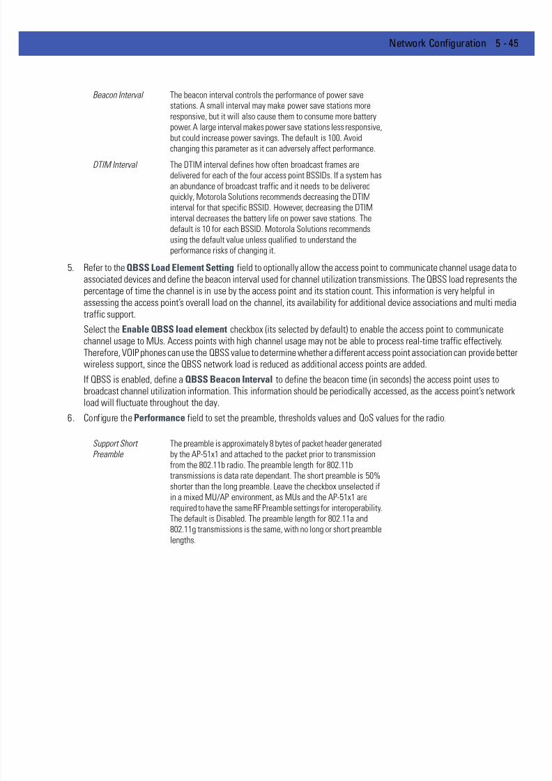
7/18/2019 Motorola AP 5131 Manual
http://slidepdf.com/reader/full/motorola-ap-5131-manual 167/613
Network Configuration 5 - 45
5. Refer to the QBSS Load Element Setting
field to optionally allow the access point to communicate channel usage data to
associated devices and define the beacon interval used for channel utilization transmissions. The QBSS load represents thepercentage of time the channel is in use by the access point and its station count. This information is very helpful inassessing the access point’s overall load on the channel, its availability for additional device associations and multi mediatraffic support.
Select the Enable QBSS load element checkbox (its selected by default) to enable the access point to communicatechannel usage to MUs. Access points with high channel usage may not be able to process real-time traffic effectively.Therefore, VOIP phones can use the QBSS value to determine whether a different access point association can provide betterwireless support, since the QBSS network load is reduced as additional access points are added.
If QBSS is enabled, define a QBSS Beacon Interval to define the beacon time (in seconds) the access point uses tobroadcast channel utilization information. This information should be periodically accessed, as the access point’s networkload will fluctuate throughout the day.
6. Configure the Performance field to set the preamble, thresholds values and QoS values for the radio.
Beacon Interval The beacon interval controls the performance of power save
stations. A small interval may make power save stations more
responsive, but it will also cause them to consume more battery
power. A large interval makes power save stations less responsive,
but could increase power savings. The default is 100. Avoidchanging this parameter as it can adversely affect performance.
DTIM Interval The DTIM interval defines how often broadcast frames are
delivered for each of the four access point BSSIDs. If a system has
an abundance of broadcast traffic and it needs to be delivered
quickly, Motorola Solutions recommends decreasing the DTIM
interval for that specific BSSID. However, decreasing the DTIM
interval decreases the battery life on power save stations. The
default is 10 for each BSSID. Motorola Solutions recommends
using the default value unless qualified to understand the
performance risks of changing it.
Support Short
Preamble
The preamble is approximately 8 bytes of packet header generated
by the AP-51x1 and attached to the packet prior to transmission
from the 802.11b radio. The preamble length for 802.11b
transmissions is data rate dependant. The short preamble is 50%
shorter than the long preamble. Leave the checkbox unselected if
in a mixed MU/AP environment, as MUs and the AP-51x1 are
required to have the same RF Preamble settings for interoperability.
The default is Disabled. The preamble length for 802.11a and
802.11g transmissions is the same, with no long or short preamble
lengths.
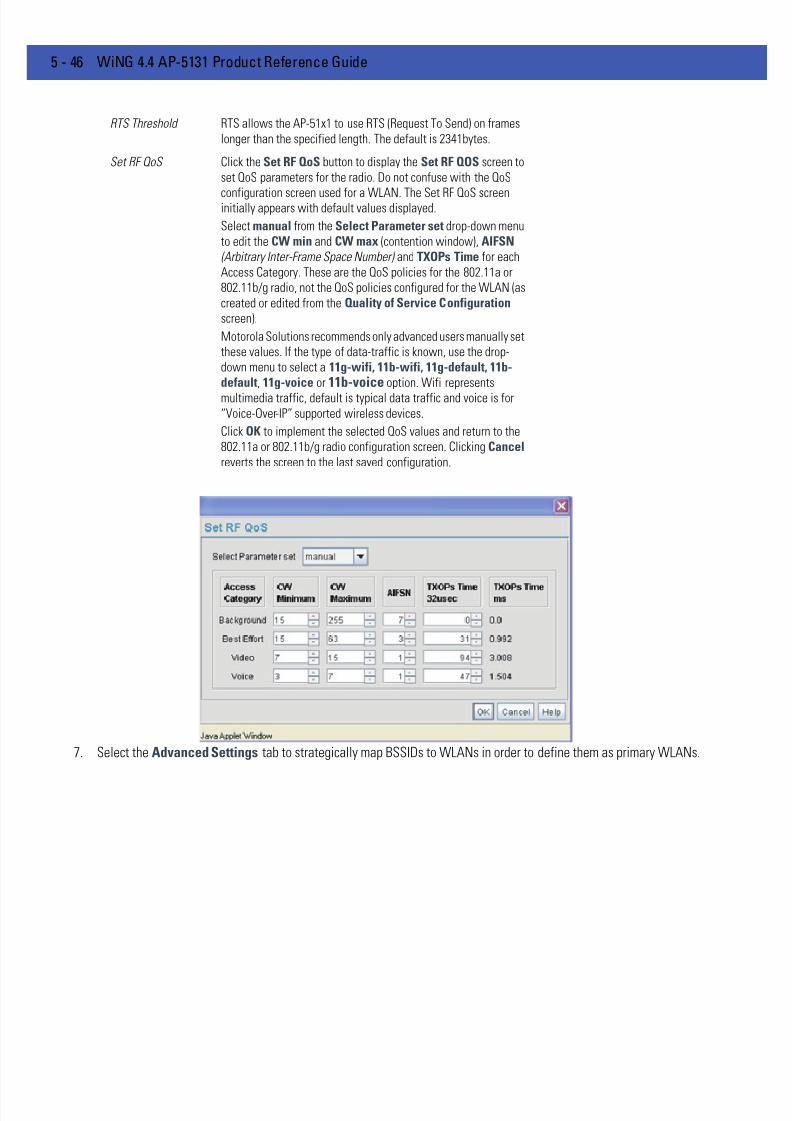
7/18/2019 Motorola AP 5131 Manual
http://slidepdf.com/reader/full/motorola-ap-5131-manual 168/613
5 - 46 WiNG 4.4 AP-5131 Product Reference Guide
7. Select the Advanced Settings tab to strategically map BSSIDs to WLANs in order to define them as primary WLANs.
RTS Threshold RTS allows the AP-51x1 to use RTS (Request To Send) on frames
longer than the specified length. The default is 2341bytes.
Set RF QoS Click the Set RF QoS button to display the Set RF QOS screen to
set QoS parameters for the radio. Do not confuse with the QoS
configuration screen used for a WLAN. The Set RF QoS screeninitially appears with default values displayed.
Select manual from the Select Parameter set drop-down menu
to edit the CW min and CW max (contention window), AIFSN
(Arbitrary Inter-Frame Space Number) and TXOPs Time for each
Access Category. These are the QoS policies for the 802.11a or
802.11b/g radio, not the QoS policies configured for the WLAN (as
created or edited from the Quality of Service Configuration
screen).
Motorola Solutions recommends only advanced users manually set
these values. If the type of data-traffic is known, use the drop-
down menu to select a 11g-wifi, 11b-wifi, 11g-default, 11b-default, 11g-voice or 11b-voice option. Wifi represents
multimedia traffic, default is typical data traffic and voice is for
“Voice-Over-IP” supported wireless devices.
Click OK to implement the selected QoS values and return to the
802.11a or 802.11b/g radio configuration screen. Clicking Cancel reverts the screen to the last saved configuration.
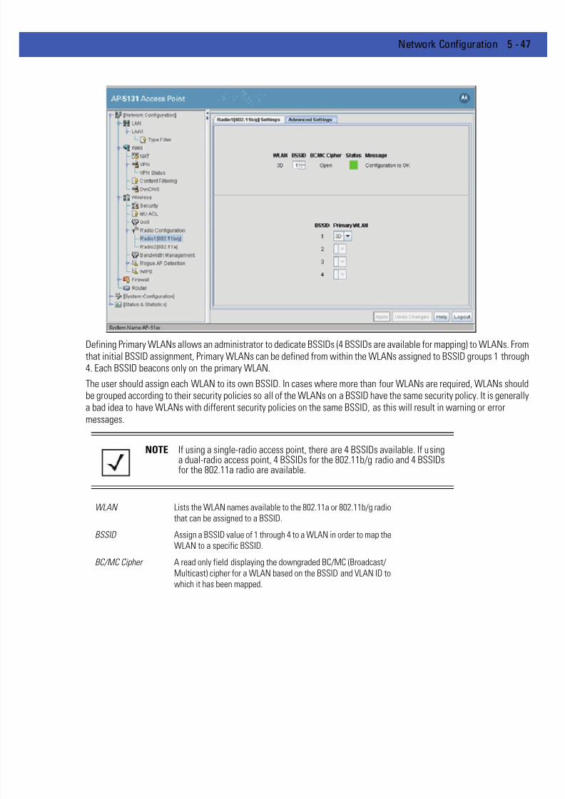
7/18/2019 Motorola AP 5131 Manual
http://slidepdf.com/reader/full/motorola-ap-5131-manual 169/613
Network Configuration 5 - 47
Defining Primary WLANs allows an administrator to dedicate BSSIDs (4 BSSIDs are available for mapping) to WLANs. Fromthat initial BSSID assignment, Primary WLANs can be defined from within the WLANs assigned to BSSID groups 1 through4. Each BSSID beacons only on the primary WLAN.
The user should assign each WLAN to its own BSSID. In cases where more than four WLANs are required, WLANs shouldbe grouped according to their security policies so all of the WLANs on a BSSID have the same security policy. It is generallya bad idea to have WLANs with different security policies on the same BSSID, as this will result in warning or error
messages.
NOTE If using a single-radio access point, there are 4 BSSIDs available. If usinga dual-radio access point, 4 BSSIDs for the 802.11b/g radio and 4 BSSIDsfor the 802.11a radio are available.
WLAN Lists the WLAN names available to the 802.11a or 802.11b/g radio
that can be assigned to a BSSID.
BSSID Assign a BSSID value of 1 through 4 to a WLAN in order to map the
WLAN to a specific BSSID.
BC/MC Cipher A read only field displaying the downgraded BC/MC (Broadcast/Multicast) cipher for a WLAN based on the BSSID and VLAN ID to
which it has been mapped.

7/18/2019 Motorola AP 5131 Manual
http://slidepdf.com/reader/full/motorola-ap-5131-manual 170/613
5 - 48 WiNG 4.4 AP-5131 Product Reference Guide
8. Use the Primary WLAN drop-down menu to select a WLAN from those WLANs sharing the same BSSID. The selectedWLAN is the primary WLAN for the specified BSSID.
9. Click Apply to save any changes to the Radio Settings and Advanced Settings screens. Navigating away from the screenwithout clicking Apply results in changes to the screens being lost.
10. Click Undo Changes (if necessary) to undo any changes made to the screen and its sub-screens. Undo Changes reverts thesettings to the last saved configuration.
11. Click Logout to securely exit the Access Point applet. A prompt displays confirming the logout before the applet is closed.
5.3.3 Configuring Bandwidth Management Settings
The AP-51x1 can be configured to grant individual WLAN’s network bandwidth priority levels. Use the BandwidthManagement screen to control the network bandwidth allotted to individual WLANs. Define a weighted scheme asneeded when WLAN traffic supporting a specific network segment becomes critical. Bandwidth management isconfigured on a per-WLAN basis. However, with this latest version 2.0 release of access point firmware, a separate tabhas been created for each access point radio. With this new segregated radio approach, bandwidth management can beconfigured uniquely for individual WLANs on different access point radios.
1. Select Network Configuration -> Wireless -> Bandwidth Management from the AP-51x1 menu tree.
Status Displays the following color coded status:
Red - Error (Invalid Configuration)
Yellow - Warning (Broadcast Downgrade)
Green - Good (Configuration is OK)
Message Displays the verbal status of the WLAN and BSSID assignments. If
the Status column displays green, the Message will typically be
Configuration is OK. If yellow, a description of invalid
configuration displays.

7/18/2019 Motorola AP 5131 Manual
http://slidepdf.com/reader/full/motorola-ap-5131-manual 171/613
Network Configuration 5 - 49
2. Select either the Radio 1(802.11b/g) orRadio 2(802.11a) tab to display the WLANs enabled for the selected radio and theirexisting configurations.
The WLANs displaying for the selected radio were assigned when the WLAN was created or modified. A single WLAN canbe assigned to either radio, and if necessary have different bandwidth management configurations. To modify a WLAN-to-
radio assignment, see Creating/Editing Individual WLANs on page 5-23 .3. Use the Bandwidth Share Mode drop-down menu to define the order enabled WLANs receive AP-51x1 services. Select
one of the following three options:
4. Configure the Bandwidth Share for Each WLAN field to set a raw weight (for WLANs using the Weighted Round-Robinoption) for each WLAN. The weight% changes as the weight is entered.
If a WLAN has not been enabled from the Wireless screen, it is not configurable using the Bandwidth Managementscreen. To enable a specific WLAN, see Enabling Wireless LANs (WLANs) on page 5-21.
5. Click Apply to save any changes to the Bandwidth Management screen. Navigating away from the screen without clickingApply results in all changes to the screens being lost.
6. Click Undo Changes (if necessary) to undo any changes made. Undo Changes reverts the settings displayed on theBandwidth Management screen to the last saved configuration.
7. Click Logout to securely exit the Access Point applet. A prompt displays confirming the logout before the applet is closed.
First In First Out WLANs receive services from the AP-51x1 on a first-come, first-
served basis. This is the default setting.
Round-Robin Each WLAN receives AP-51x1 services in turn as long theAP-51x1 has data traffic to forward.
Weighted Round-
Robin
If selected, a weighting (prioritization) scheme (configured within
the QoS Configuration screen) is used to define which WLANs
receive AP-51x1 resources first.
WLAN Name Displays the name of the WLAN. This field is read-only. To change
the name of the WLAN, see Creating/Editing Individual WLANs on
page 5-23 .
Weight This column is not available unless Weighted Round-Robin is
selected. Assign a weight to each WLAN. This percentage equals
the AP-51x1 bandwidth share for that WLAN when network traffic
is detected.
Weight (%) This column is automatically updated with the appropriate WLAN
bandwidth share when the Weight is modified.
QoS Policy Displays the name of the QoS policy defined for each WLAN within
the Quality of Service for WLAN screen. If no policy has been
set, the WLAN uses the default policy. For information on assigning
QoS policies for specific WLANs, see Setting the WLAN Quality of
Service (QoS) Policy on page 5-29 .
NOTE Though the Rogue AP and Firewall features appear after the BandwidthManagement features within the AP-51x1 menu tree, they are describedin Chapter 6, Configuring Access Point Security on page 6-1, as both itemsare data protection functions. More specifically, see, Configuring Firewal lSettings on page 6-25 and Configuring Rogue AP Detection on page 6-48 .

7/18/2019 Motorola AP 5131 Manual
http://slidepdf.com/reader/full/motorola-ap-5131-manual 172/613
5 - 50 WiNG 4.4 AP-5131 Product Reference Guide
5.4 Configuring WIPS Server Settings
With this most recent release of the access point firmware, an access point radio can function as a Wireless IntrusionProtection System (WIPS) sensor and upload sensor mode operation information to its parent WIPS Server. Either or bothof the access point’s radios can be set as a WIPS sensor. When an access point radio is functioning as a WIPS sensor, itis able to scan in sensor mode across all available channels.
Additionally, use the WIPS screen to define a primary and alternate WIPS server to submit event information for usewithin the WIPS console for device management and potential threat notification.
To define the attributes of the WIPS Server:
1. Select Network Configuration -> Wireless -> WIPS from the AP-51x1 menu tree.
2. Within the WIPS Status field, define whether the access point’s 802.11a or 802.11b/g radio is servicing its coverage areaas a typical access point or as a WIPS sensor.
Selecting the disabled radio button defines the radio as a typical access point. Selecting the enabled radio button definesthe radio as a WIPS sensor.
3. Define a primary and alternate WIPS server IP Address within the WIPS Server 1 and WIPS Server 2 fields.
This is the address of the WIPS console server.
4. Click Apply to save any changes to the WIPS screen. Navigating away from the screen without clicking Apply results in allchanges to the screens being lost.
5. Click Undo Changes (if necessary) to undo any changes made. Undo Changes reverts the settings displayed on the WIPSscreen to the last saved configuration.
6. Click Logout to securely exit the access point applet. A prompt displays confirming the logout before the applet is closed.
NOTE The AP-51x1 radios are dual band capable radios. When selected as a
WIPS sensor these radios scan both the 2.4 GHz and 5 GHz bands.

7/18/2019 Motorola AP 5131 Manual
http://slidepdf.com/reader/full/motorola-ap-5131-manual 173/613
Network Configuration 5 - 51
5.5 Configuring Router Settings
The AP-51x1 router uses routing tables and protocols to forward data packets from one network to another. The AP-51x1router manages traffic within the network, and directs traffic from the WAN to destinations on the AP-51x1 managed LAN.Use the AP-51x1 Router screen to view the router's connected routes. To access the Router screen.
1. Select Network Configuration -> Router from the AP-51x1 menu tree.
2. Refer to the AP-51x1 Router Table field to view existing routes.
The AP-51x1 Router Table field displays a list of connected routes between an enabled subnet and the router. These routescan be changed by modifying the IP address and subnet masks of the enabled subnets.
The information in the AP-51x1 Router Table is dynamically generated from settings applied on the WAN screen. Thedestination for each subnet is its IP address. The subnet mask (or network mask) and gateway settings are those belongingto each subnet. Displayed interfaces are those associated with destination IP addresses. To change any of the networkaddress information within the WAN screen, see Configuring WAN Settings on page 5-13 .
3. From the Use Default Gateway drop-down menu, select the WAN or either of the two LANs (if enabled) to server as thedefault gateway to forward data packets from one network to another.
4. To set or view the RIP configuration, click the RIP Configuration button.
Routing Information Protocol (RIP) is an interior gateway protocol that specifies how routers exchange routing-tableinformation. The Router screen also allows the administrator to select the type of RIP and the type of RIP authentication usedby the switch. For more information on configuring RIP, see Setting the RIP Configuration on page 5-52 .
5. Use the User Defined Routes field to add or delete static routes.
The User Defined Routes field allows the administrator to view, add or delete internal static (dedicated) routes.
a. Click the Add button to create a new table entry.
b. Highlight an entry and click the Del (delete) button to remove an entry.
c. Specify the destination IP address, subnet mask, and gateway information for the internal static route.

7/18/2019 Motorola AP 5131 Manual
http://slidepdf.com/reader/full/motorola-ap-5131-manual 174/613
5 - 52 WiNG 4.4 AP-5131 Product Reference Guide
d. Select an enabled subnet from the Interface(s) column’s drop-down menu to complete the table entry. Information inthe Metric column is a user-defined value (from 1 to 65535) used by router protocols to determine the best hop routes.
6. Click the Apply button to save the changes.
7. Click Logout to securely exit the access point applet. A prompt displays confirming the logout before the applet is closed.
5.5.1 Setting the RIP Configuration
To set the RIP configuration:
1. From within the RIP Configuration field, select the RIP Type from the drop-down menu. The following options are available:
2. Select a routing direction from the RIP Direction drop-down menu. Both (for both directions), Rx only (receive only), andTX only (transmit only) are available options.
No RIP The No RIP option prevents the access point’s router from
exchanging routing information with other routers. Routing
information may not be appropriate to share, for example, if the
access point manages a private LAN.
RIP v1 RIP version 1 is a mature, stable, and widely supported protocol. It
is well suited for use in stub networks and in small autonomous
systems that do not have enough redundant paths to warrant the
overhead of a more sophisticated protocol.
RIP v2 (v1 compat) RIP version 2 (compatible with version 1) is an extension of RIP v1’s
capabilities, but it is still compatible with RIP version 1. RIP version
2 increases the amount of packet information to provide the a
simple authentication mechanism to secure table updates.
RIP v2 RIP version 2 enables the use of a simple authentication
mechanism to secure table updates. More importantly, RIP version
2 supports subnet masks, a critical feature not available in RIP
version 1. This selection is not compatible with RIP version 1
support.
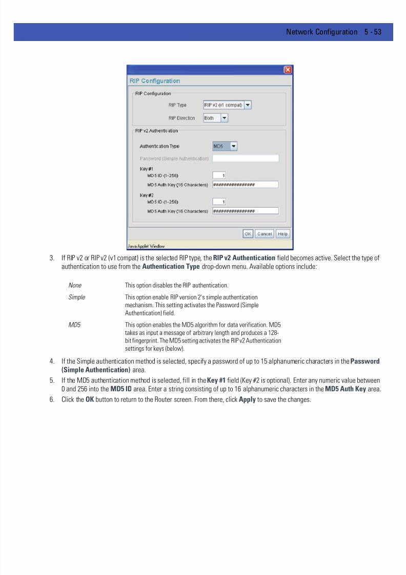
7/18/2019 Motorola AP 5131 Manual
http://slidepdf.com/reader/full/motorola-ap-5131-manual 175/613
Network Configuration 5 - 53
3. If RIP v2 or RIP v2 (v1 compat) is the selected RIP type, the RIP v2 Authentication field becomes active. Select the type ofauthentication to use from the Authentication Type drop-down menu. Available options include:
4. If the Simple authentication method is selected, specify a password of up to 15 alphanumeric characters in the Password(Simple Authentication) area.
5. If the MD5 authentication method is selected, fill in the Key #1 field (Key #2 is optional). Enter any numeric value between0 and 256 into the MD5 ID area. Enter a string consisting of up to 16 alphanumeric characters in the MD5 Auth Key area
6. Click the OK button to return to the Router screen. From there, click Apply to save the changes.
None This option disables the RIP authentication.
Simple This option enable RIP version 2’s simple authentication
mechanism. This setting activates the Password (Simple
Authentication) field.
MD5 This option enables the MD5 algorithm for data verification. MD5
takes as input a message of arbitrary length and produces a 128-
bit fingerprint. The MD5 setting activates the RIP v2 Authentication
settings for keys (below).

7/18/2019 Motorola AP 5131 Manual
http://slidepdf.com/reader/full/motorola-ap-5131-manual 176/613
5 - 54 WiNG 4.4 AP-5131 Product Reference Guide

7/18/2019 Motorola AP 5131 Manual
http://slidepdf.com/reader/full/motorola-ap-5131-manual 177/613
CHAPTER 6 CONFIGURING ACCESS POINT
SECURITY
Security measures for the AP-51x1 and its WLANs are critical. Use the available AP-51x1 security options to protect theAP-51x1 LAN from wireless vulnerabilities, and safeguard the transmission of RF packets between the AP-51x1 and itsassociated MUs.
WLAN security can be configured on an ESS by ESS basis on the AP-51x1. Sixteen separate ESSIDs (WLANs) can besupported on an AP-51x1, and must be managed (if necessary) between the 802.11a and 802.11b/g radio. The user hasthe capability of configuring separate security policies for each WLAN. Each security policy can be configured based onthe authentication (Kerberos, 802.1x EAP) or encryption (WEP, KeyGuard, WPA/TKIP or WPA2/CCMP) scheme best suitedto the coverage area that security policy supports.
The AP-51x1 can also create VPN tunnels to securely route traffic through a IPSEC tunnel and block transmissions withdevices interpreted as Rogue APs.
NOTE Security for the AP-51x1 can be configured in various locations throughoutthe AP-51x1 menu structure. This chapter outlines the security optionsavailable to the AP-51x1, and the menu locations and steps required toconfigure specific security measures.

7/18/2019 Motorola AP 5131 Manual
http://slidepdf.com/reader/full/motorola-ap-5131-manual 178/613
6 - 2 WiNG 4.4 AP-5131 Product Reference Guide
6.1 Configuring Security Options
To configure the data protection options available on the AP-51x1, refer to the following:
• To set an administrative password for secure AP-51x1 logins, see Setting Passwords on page 6-3 .
• To display security policy screens used to configure the authetication and encryption schemes available to the AP-51x1,see Enabling Authentication and Encryption Schemes on page 6-5 . These security policies can be used on more thanone WLAN.
• To create a security policy supporting 802.1x EAP, see Configuring 802.1x EAP Authentication on page 6-11.
• To define a security policy supporting Kerberos, see, Configuring Kerberos Authentication on page 6-8 .
• To create a security policy supporting WEP, see Configuring WEP Encryption on page 6-15 .
• To configure a security policy supporting KeyGuard, see, Configuring KeyGuard Encryption on page 6-17 .
• To define a security policy supporting WPA-TKIP, see Configuring WPA/WPA2 Using TKIP on page 6-19 .
• To create a security policy supporting WPA2-CCMP, see Configuring WPA2-CCMP (802.11i) on page 6-22 .
• To configure the AP-51x1 to block specific kinds of HTTP, SMTP and FTP data traffic, see Configuring Firewall Settingson page 6-25 .
• To create VPN tunnels allowing traffic to route securely through a IPSEC tunnel to a private network, see ConfiguringVPN Tunnels on page 6-32 .
• To configure the AP-51x1 to block transmissions with devices detected as Rogue AP’s (hostile devices), see ConfiguringRogue AP Detection on page 6-48 .
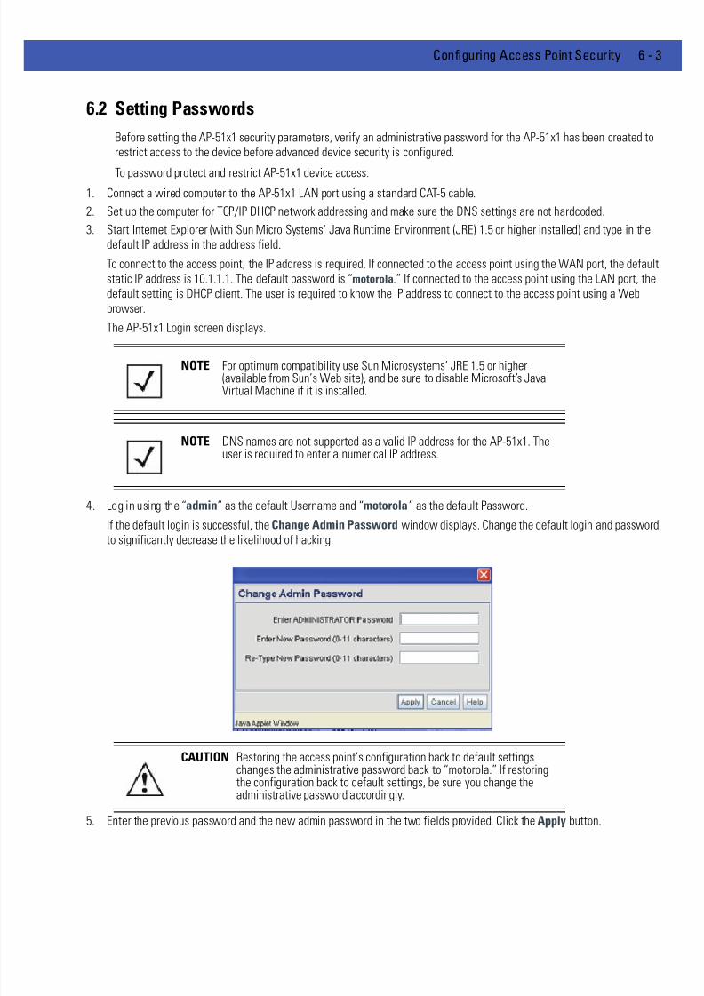
7/18/2019 Motorola AP 5131 Manual
http://slidepdf.com/reader/full/motorola-ap-5131-manual 179/613
Configuring Access Point Security 6 - 3
6.2 Setting Passwords
Before setting the AP-51x1 security parameters, verify an administrative password for the AP-51x1 has been created torestrict access to the device before advanced device security is configured.
To password protect and restrict AP-51x1 device access:1. Connect a wired computer to the AP-51x1 LAN port using a standard CAT-5 cable.
2. Set up the computer for TCP/IP DHCP network addressing and make sure the DNS settings are not hardcoded.
3. Start Internet Explorer (with Sun Micro Systems’ Java Runtime Environment (JRE) 1.5 or higher installed) and type in thedefault IP address in the address field.
To connect to the access point, the IP address is required. If connected to the access point using the WAN port, the defaultstatic IP address is 10.1.1.1. The default password is “motorola.” If connected to the access point using the LAN port, thedefault setting is DHCP client. The user is required to know the IP address to connect to the access point using a Webbrowser.
The AP-51x1 Login screen displays.
4. Log in using the “admin” as the default Username and “motorola” as the default Password.
If the default login is successful, the Change Admin Password window displays. Change the default login and passwordto significantly decrease the likelihood of hacking.
5. Enter the previous password and the new admin password in the two fields provided. Click the Apply button.
NOTE For optimum compatibility use Sun Microsystems’ JRE 1.5 or higher(available from Sun’s Web site), and be sure to disable Microsoft’s JavaVirtual Machine if it is installed.
NOTE DNS names are not supported as a valid IP address for the AP-51x1. Theuser is required to enter a numerical IP address.
CAUTION Restoring the access point’s configuration back to default settingschanges the administrative password back to “motorola.” If restoringthe configuration back to default settings, be sure you change theadministrative password accordingly.

7/18/2019 Motorola AP 5131 Manual
http://slidepdf.com/reader/full/motorola-ap-5131-manual 180/613
6 - 4 WiNG 4.4 AP-5131 Product Reference Guide
Once the admin password has been created/updated, the System Settings screen displays. If the AP-51x1 has not had itsSystem Settings (device name, location etc.) configured, see Configuring System Settings on page 4-3 .
Once the password has been set, refer back to Configuring Security Options on page 6-2 to determine which AP-51x1security feature to configure next.
6.2.1 Resetting the Access Point Password
The access point has a means of restoring its password to its default value. Doing so also reverts the access point’ssecurity, radio and power management configuration to their default settings. Only an installation professional shouldreset the access point’s password and promptly define a new restrictive password.
To contact Motorola Solutions Support in the event of a password reset requirement, go to:
http://www.symbol.com/contactsupport
CAUTION Only a qualified installation professional should set or restore theaccess point’s radio and power management configuration in the
event of a password reset.
7/18/2019 Motorola AP 5131 Manual
http://slidepdf.com/reader/full/motorola-ap-5131-manual 181/613
Configuring Access Point Security 6 - 5
6.3 Enabling Authentication and Encryption Schemes
To complement the built-in firewall filters on the WAN side of the AP-51x1, the WLAN side of the AP-51x1 supportsauthentication and encryption schemes. Authentication is a challenge-response procedure for validating user credentialssuch as username, password, and sometimes secret-key information. The AP-51x1 provides two schemes forauthenticating users: 802.1x EAP and Kerberos .
Encryption applies a specific algorithm to alter its appearance and prevent unauthorized reading. Decryption applies thealgorithm in reverse to restore the data to its original form. Sender and receiver must employ the same encryption/decryption method to interoperate.
Wired Equivalent Privacy (WEP) is available in two encryption modes: 40 bit (also called WEP 64) and 104 bit (also calledWEP 128). The 104-bit encryption mode provides a longer algorithm (better security) that takes longer to decode (hack)than the 40-bit encryption mode.
Each WLAN (16 WLANs available in total to an AP-51x1 regardless of the model) can have a separate security policy.However, more than one WLAN can use the same security policy. Therefore, to avoid confusion, do not name securitypolicies the same name as WLANs. Once security policies have been created, they are selectable within the Security field
of each WLAN screen. If the existing default security policy does not satisfy the data protection requirements of a specificWLAN, a new security policy (using the authentication and encryption schemes discussed above) can be created.
To enable an existing WLAN security policy or create a new policy:
1. Select Network Configuration -> Wireless -> Security from the AP-51x1 menu tree.
The Security Configuration screen displays.
2. If a new security policy is required, click the Create button.
The New Security Policy screen displays with the Manually Pre-shared key/No authentication and No Encryptionoptions selected. Naming and saving such a policy (as is) would provide no security and might only make sense in a guestnetwork wherein no sensitive data is either transmitted or received.
However, selecting any other authetnication or encryption checkbox displays a configuration field for the selected security
scheme within the New Security Policy screen.
3. Use the Name field to define a logical security policy name.
Remember, multiple WLANs can share the same security policy, so be careful not to name security policies after specificWLANs or risk defining a WLAN to single policy. Motorola Solutions recommends naming the policy after the attributes ofthe authentication or encryption type selected (for example, WPA2 Allow TKIP ).
4. Enable and configure an Authentication option if necessary for the target security policy.
NOTE An existing security policy can be edited from the Security Configurationscreen by selecting an existing policy and clicking the Edit button. Use theEdit Security Policy screen to edit the policy. For more information onediting an existing security policy, refer to security configuration sectionsdescribed in steps 4 and 5.
Manually Pre-Shared
Key / No
Authentication
Select this button to disable authentication. This is the default
value for the Authentication field.

7/18/2019 Motorola AP 5131 Manual
http://slidepdf.com/reader/full/motorola-ap-5131-manual 182/613
6 - 6 WiNG 4.4 AP-5131 Product Reference Guide
5. Enable and configure an Encryption option if necessary for the target security policy.
6. Click Apply to keep changes made within the New Security Policy screen (if any).
Configure encryption or authentication supported security policies by referring to the following:
AP-51x1 authentication:
• To create a security policy supporting Kerberos, see, Configuring Kerberos Authentication on page 6-8 .
• To define a security policy supporting 802.1x EAP, see Configuring 802.1x EAP Authentication on page 6-11.
AP-51x1 encryption:
• To create a security policy supporting WEP, see Configuring WEP Encryption on page 6-15 .
• To define a security policy supporting KeyGuard, see, Configuring KeyGuard Encryption on page 6-17 .
• To configure a security policy supporting WPA/TKIP, see Configuring WPA/WPA2 Using TKIP on page 6-19 .
• To create a security policy supporting WPA2/CCMP, see Configuring WPA2-CCMP (802.11i) on page 6-22 .
Kerberos Select the Kerberos button to display the KerberosConfiguration field within the New Security Policy screen. For
specific information on configuring Kerberos, see Configuring
Kerberos Authentication on page 6-8 .
802.1x EAP Select the 802.1x EAP button to display the 802.1x EAP Settingsfield within the New Security Policy screen. For specific
information on configuring EAP, see Configuring 802.1x EAP
Authentication on page 6-11.
No Encryption If No Encryption is selected, encryption is disabled for the
security policy. If security is not an issue, this setting avoids the
overhead an encryption protocol causes on the AP-51x1. No
Encryption is the default value for the Encryption field.
WEP 64 (40-bit key) Select the WEP 64 (40 bit key) button to display the WEP 64
Settings field within the New Security Policy screen. For specificinformation on configuring WEP 64, see Configuring WEP
Encryption on page 6-15 .
WEP 128 (104-bit key) Select the WEP 128 (104 bit key) button to display the WEP 128Settings field within the New Security Policy screen. For specific
information on configuring WEP 128, see Configuring WEP
Encryption on page 6-15 .
KeyGuard Select the KeyGuard button to display the KeyGuard Settings
field within the New Security Policy screen. For specific
information on configuring KeyGuard, see Configuring KeyGuard
Encryption on page 6-17 .
WPA/WPA2 TKIP Select the WPA/WPA2 TKIP button to display the WPA/TKIPSettings field within the New Security Policy screen. For specific
information on configuring WPA/WPA2 TKIP, see Configuring
WPA/WPA2 Using TKIP on page 6-19 .
WPA2/CCMP
(802.11i)
Select the WPA2/CCMP (802.11) button to display the WPA2/ CCMP Settings field within the New Security Policy screen. For
detailed information on configuring WPA2/CCMP, see Configuring
WPA2-CCMP (802.11i) on page 6-22 .

7/18/2019 Motorola AP 5131 Manual
http://slidepdf.com/reader/full/motorola-ap-5131-manual 183/613
Configuring Access Point Security 6 - 7
7. Click Cancel to return to the target WLAN screen without keeping any of the changes made within the New Security Policyscreen.
7/18/2019 Motorola AP 5131 Manual
http://slidepdf.com/reader/full/motorola-ap-5131-manual 184/613
6 - 8 WiNG 4.4 AP-5131 Product Reference Guide
6.4 Configuring Kerberos Authentication
Kerberos (designed and developed by MIT) provides strong authentication for client/server applications using secret-keycryptography. Using Kerberos, a client must prove its identity to a server (and vice versa) across an insecure network connection
Once a client and server use Kerberos to prove their identity, they can encrypt all communications to assure privacy and data
integrity. Kerberos can only be used on the access point with Motorola Solutions 802.11b clients.
Kerberos uses the Network Time Protocol (NTP) for synchronizing the clocks of its Key Distribution Center (KDC) server(s) . Usethe NTP Servers screen to specify the IP addresses and ports of available NTP servers. Kerberos requires the Enable NTP oncheckbox be selected for authentication to function properly. See Configuring Network Time Protocol (NTP) on page 4-33 toconfigure the NTP server.
To configure Kerberos on the AP-51x1:
1. Select Network Configuration -> Wireless -> Security from the AP-51x1 menu tree.
If security policies supporting Kerberos exist, they appear within the Security Configuration screen. These existing policies cabe used as is, or their properties edited by clicking the Edit button. To configure a new security policy supporting Kerberos,continue to step 2.
2. Click the Create button to configure a new policy supporting Kerberos.
The New Security Policy screen displays with no authentication or encryption options selected.3. Select the Kerberos radio button.
The Kerberos Configuration field displays within the New Security Policy screen.
4. Ensure the Name of the security policy entered suits the intended configuration or function of the policy.
CAUTION Kerberos makes no provisions for host security. Kerberos assumesthat it is running on a trusted host with an untrusted network. If hostsecurity is compromised, Kerberos is compromised as well
NOTE If 802.11a is selected as the radio used for a specific WLAN, the WLANcannot use a Kerberos supported security policy, as no Motorola Solutions802.11a clients can support Kerberos.

7/18/2019 Motorola AP 5131 Manual
http://slidepdf.com/reader/full/motorola-ap-5131-manual 185/613
Configuring Access Point Security 6 - 9
5. Set the Kerberos Configuration field as required to define the parameters of the Kerberos authentication server andAP-51x1.
6. Click the Apply button to return to the WLAN screen to save any changes made within the Kerberos Configuration field ofthe New Security Policy screen.
Realm Name Specify a realm name that is case-sensitive, for example,
MOTOROLA.COM. The realm name is the name domain/realm
name of the KDC Server. A realm name functions similarly to a DNS
domain name. In theory, the realm name is arbitrary. However, in
practice a Kerberos realm is named by uppercasing the DNS
domain name that is associated with hosts in the realm.
Primary KDC Specify a numerical (non-DNS) IP address and port for the primary
Key Distribution Center (KDC). The KDC implements an
Authentication Service and a Ticket Granting Service, whereby an
authorized user is granted a ticket encrypted with the user's
password. The KDC has a copy of every user password.
Backup KDC Optionally, specify a numerical (non-DNS) IP address and port for a
backup KDC. Backup KDCs are referred to as slave servers. The
slave server periodically synchronizes its database with the
primary (or master) KDC.Remote KDC Optionally, specify a numerical (non-DNS) IP address and port for a
remote KDC. Kerberos implementations can use an administration
server allowing remote manipulation of the Kerberos database.
This administration server usually runs on the KDC.
Port Specify the ports on which the Primary, Backup and Remote KDCs
reside. The default port number for Kerberos Key Distribution
Centers is Port 88.

7/18/2019 Motorola AP 5131 Manual
http://slidepdf.com/reader/full/motorola-ap-5131-manual 186/613
6 - 10 WiNG 4.4 AP-5131 Product Reference Guide
7. Click the Cancel button to undo any changes made within the Kerberos Configuration field and return to the WLAN screen.This reverts all settings for the Kerberos Configuration field to the last saved configuration.
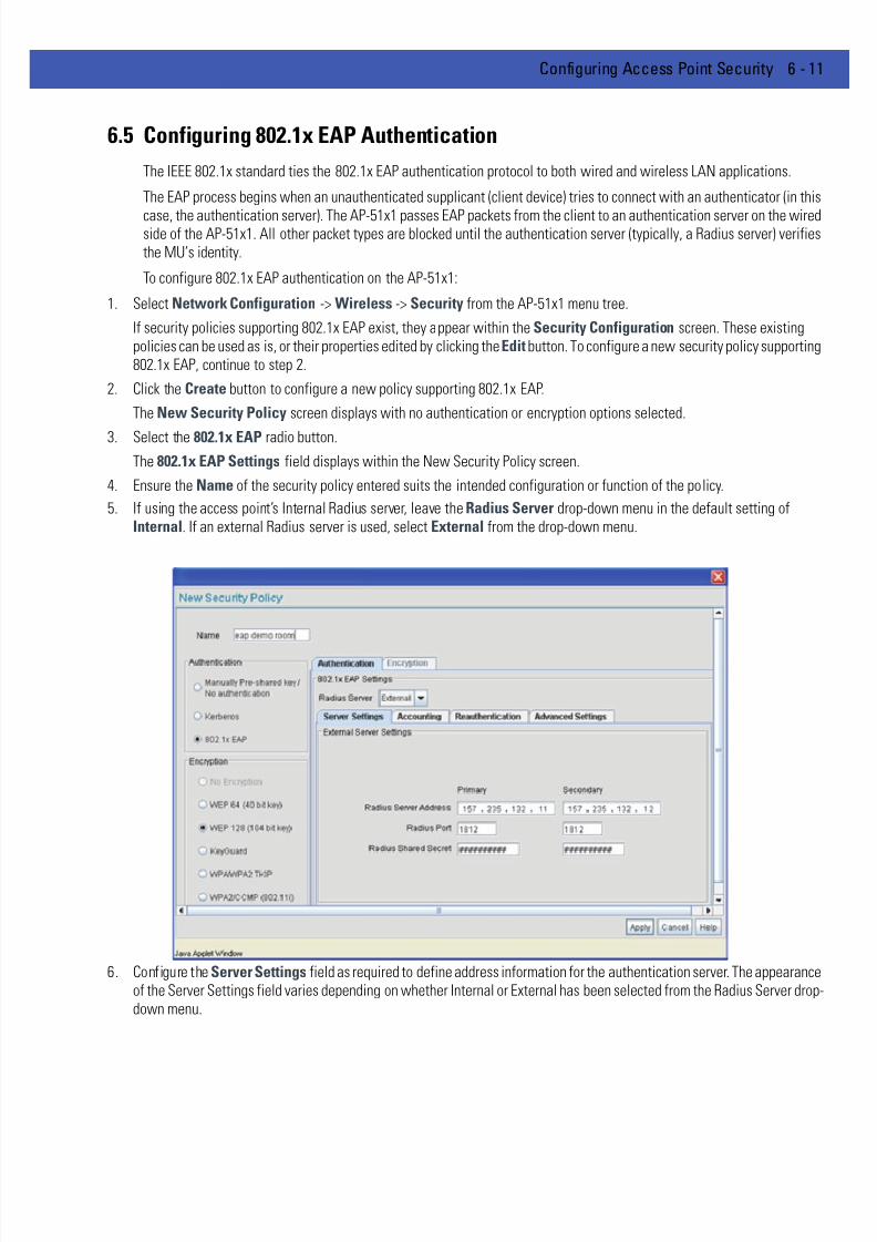
7/18/2019 Motorola AP 5131 Manual
http://slidepdf.com/reader/full/motorola-ap-5131-manual 187/613
Configuring Access Point Security 6 - 11
6.5 Configuring 802.1x EAP Authentication
The IEEE 802.1x standard ties the 802.1x EAP authentication protocol to both wired and wireless LAN applications.
The EAP process begins when an unauthenticated supplicant (client device) tries to connect with an authenticator (in this
case, the authentication server). The AP-51x1 passes EAP packets from the client to an authentication server on the wiredside of the AP-51x1. All other packet types are blocked until the authentication server (typically, a Radius server) verifiesthe MU’s identity.
To configure 802.1x EAP authentication on the AP-51x1:
1. Select Network Configuration -> Wireless -> Security from the AP-51x1 menu tree.
If security policies supporting 802.1x EAP exist, they appear within the Security Configuration screen. These existingpolicies can be used as is, or their properties edited by clicking the Edit button. To configure a new security policy supporting802.1x EAP, continue to step 2.
2. Click the Create button to configure a new policy supporting 802.1x EAP.
The New Security Policy screen displays with no authentication or encryption options selected.
3. Select the 802.1x EAP radio button.
The 802.1x EAP Settings field displays within the New Security Policy screen.
4. Ensure the Name of the security policy entered suits the intended configuration or function of the policy.
5. If using the access point’s Internal Radius server, leave the Radius Server drop-down menu in the default setting ofInternal. If an external Radius server is used, select External from the drop-down menu.
6. Configure the Server Settings field as required to define address information for the authentication server. The appearanceof the Server Settings field varies depending on whether Internal or External has been selected from the Radius Server dropdown menu.

7/18/2019 Motorola AP 5131 Manual
http://slidepdf.com/reader/full/motorola-ap-5131-manual 188/613
6 - 12 WiNG 4.4 AP-5131 Product Reference Guide
Radius Server
Address
If using an External Radius Server, specify the numerical (non-DNS)
IP address of a primary Remote Dial-In User Service (Radius) server.
Optionally, specify the IP address of a secondary server. The
secondary server acts as a failover server if the primary server
cannot be contacted. An ISP or a network administrator providesthese addresses.
Radius is a client/server protocol and software enabling remote-
access clients to communicate with a server used to authenticate
users and authorize access to the requested system or service. This
setting is not available if Internal has been selected from the
Radius Server drop-down menu.
RADIUS Port If using an External Radius Server, specify the port on which the
primary Radius server is listening. Optionally, specify the port of a
secondary (failover) server. Older Radius servers listen on ports
1645 and 1646. Newer servers listen on ports 1812 and 1813. Port
1645 or 1812 is used for authentication. Port 1646 or 1813 is used
for accounting. The ISP or a network administrator needs to confirmthe appropriate primary and secondary port numbers for
authentication. This setting is not available if Internal has been
selected from the Radius Server drop-down menu.
RADIUS Shared
Secret
Specify a shared secret for authentication on the Internal or
Primary Radius server (External Radius Server only). The shared
secret is required to match the shared secret on the Radius server.
Optionally, specify a shared secret for a secondary (failover) server.
Use shared secrets to verify Radius messages (with the exception
of the Access-Request message) sent by a Radius enabled device
configured with the same shared secret.
Apply the qualifications of a well-chosen password to the
generation of a shared secret. Generate a random, case-sensitivestring using letters and numbers. Verify the shared secret is at least
22 characters to protect the Radius server from brute-force attacks.
An example of a strong and secure shared secret is:
8d#>9fq4bV)H7%a3-zE13sW.

7/18/2019 Motorola AP 5131 Manual
http://slidepdf.com/reader/full/motorola-ap-5131-manual 189/613
Configuring Access Point Security 6 - 13
7. Select the Accounting tab as required to define a timeout period and retry interval Syslog for MUs interoperating with theAP-51x1 and EAP authentication server. The items within this tab could be enabled or disabled depending on whetherInternal or External has been selected from the Radius Server drop-down menu.
8. Select the Reauthentication tab as required to define authentication connection policies, intervals and maximum retries.The items within this tab are identical regardless of whether Internal or External is selected from the Radius Server drop-down menu.
9. Select the Advanced Settings tab as required to specify a MU quiet period, timeout interval, transmit period, and retryperiod for MUs and the authentication server. The items within this tab are identical regardless of whether Internal orExternal is selected from the Radius Server drop-down menu.
External RadiusServer Address Specify the IP address of the external Radius server used to provideRadius accounting.
External Radius Port Specify the port on which the Radius server is listening. The default
port is 1813.
External Radius
Shared Secret
Specify a shared secret for authentication. The shared secret is
required to match the shared secret on the Radius server.
MU Timeout Specify the time (in seconds) for the access point’s retransmission
of EAP-Request packets. The default is 10 seconds. If this time is
exceeded, the authentication session is terminated.
Retries Specify the number of retries for the MU to retransmit a missed
frame to the Radius server before it times out of the authentication
session. The default is 2 retries.
Enable Syslog Select the Enable Syslog checkbox to enable Radius accounting
syslog messages relating to EAP events to be written to the
specified syslog server.
Syslog Server IP
Address
Enter the IP address of the destination syslog server to be used to
log EAP events.
Enable
Reauthentication
Select the Enable Reauthentication checkbox to configure a
wireless connection policy so MUs are forced to reauthenticateperiodically. Periodic repetition of the EAP process provides
ongoing security for current authorized connections.
Period (30-9999) secs Set the EAP reauthentication period to a shorter interval for tighter
security on the WLAN's connections. Set the EAP reauthentication
period to a longer time interval (at most, 9999 seconds) to relax
security on wireless connections. The default interval of 3600
seconds is recommended.
Max. Retries (1-99)
retries
Define the maximum number of MU retries to reauthenticate after
failing to complete the EAP process. Failure to reauthenticate in the
specified number of retries results in a terminated connection. The
default is 2 retries.
NOTE The default values described are the recommended values. Do not changethese values unless consulted otherwise by an administrator.

7/18/2019 Motorola AP 5131 Manual
http://slidepdf.com/reader/full/motorola-ap-5131-manual 190/613
6 - 14 WiNG 4.4 AP-5131 Product Reference Guide
10. Click the Apply button to save any changes made within the 802.1x EAP Settings field (including all 5 selectable tabs) ofthe New Security Policy screen.
11. Click the Cancel button to undo any changes made within the 802.1x EAP Settings field and return to the WLAN screen.This reverts all settings for the 802.1x EAP Settings field to the last saved configuration.
MU Quiet Period
(1-65535) secs
Specify an idle time (in seconds) between MU authentication
attempts, as required by the authentication server. The default is
10 seconds.
MU Timeout(1-255) secs Define the time (in seconds) for the access point’s retransmissionof EAP-Request packets. The default is 10 seconds.
MU Tx Period
(1-65635) secs
Specify the time period (in seconds) for the access point's
retransmission of the EAP Identity Request frame. The default is 5
seconds.
MU Max Retries
(1-10) retries
Specify the maximum number of times the access point retransmits
an EAP-Request frame to the client before it times out the
authentication session. The default is 2 retries.
Server Timeout
(1-255) secs
Specify the time (in seconds) for the access point's retransmission
of EAP-Request packets to the server. The default is 5 seconds. If
this time is exceeded, the authetnication session is terminated.
Server Max Retries(1-255 retries)
Specify the maximum number of times for the access point toretransmit an EAP-Request frame to the server before it times out
the authentication session. The default is 2 retries.

7/18/2019 Motorola AP 5131 Manual
http://slidepdf.com/reader/full/motorola-ap-5131-manual 191/613
Configuring Access Point Security 6 - 15
6.6 Configuring WEP Encryption
Wired Equivalent Privacy (WEP) is a security protocol specified in the IEEE Wireless Fidelity (Wi-Fi) standard. WEP isdesigned to provide a WLAN with a level of security and privacy comparable to that of a wired LAN.
WEP may be all that a small-business user needs for the simple encryption of wireless data. However, networks thatrequire more security are at risk from a WEP flaw. The existing 802.11 standard alone offers administrators no effectivemethod to update keys.
To configure WEP on the AP-51x1:
1. Select Network Configuration -> Wireless -> Security from the AP-51x1 menu tree.
If security policies supporting WEP exist, they appear within the Security Configuration screen. These existing policiescan be used as is, or their properties edited by clicking the Edit button. To configure a new security policy supporting WEP,continue to step 2.
2. Click the Create button to configure a new policy supporting WEP.
The New Security Policy screen displays with no authentication or encryption options selected.
3. Select either the WEP 64 (40 bit key) or WEP 128 (104 bit key) radio button.
The WEP 64 Settings or WEP 128 Settings field displays within the New Security Policy screen.
4. Ensure the Name of the security policy entered suits the intended configuration or function of the policy.
5. Configure the WEP 64 Settings or WEP 128 Settings field as required to define the Pass Key used to generate the WEPkeys. These keys must be the same between the access point and its MU to encrypt packets between the two devices.

7/18/2019 Motorola AP 5131 Manual
http://slidepdf.com/reader/full/motorola-ap-5131-manual 192/613
6 - 16 WiNG 4.4 AP-5131 Product Reference Guide
Default (hexadecimal) keys for WEP 64 include:
Default (hexadecimal) keys for WEP 128 include:
6. Click the Apply button to save any changes made within the WEP 64 Setting or WEP 128 Setting field of the New SecurityPolicy screen.
7. Click the Cancel button to undo any changes made within the WEP 64 Setting or WEP 128 Setting field and return to the WLAN screen. This reverts all settings to the last saved configuration.
Pass Key Specify a 4 to 32 character pass key and click the Generate button.
The pass key can be any alphanumeric string. The AP-51x1, other
proprietary routers and Motorola Solutions MUs use the algorithm
to convert an ASCII string to the same hexadecimal number. MUs
without Motorola Solutions adapters need to use WEP keysmanually configured as hexadecimal numbers.
Keys #1-4 Use the Key #1-4 areas to specify key numbers. The key can be
either a hexadecimal or ASCII depending on which option is
selected from the drop-down menu. For WEP 64 (40-bit key), the
keys are 10 hexadecimal characters in length or 5 ASCII characters.
For WEP 128 (104-bit key), the keys are 26 hexadecimal characters
in length or 13 ASCII characters. Select one of these keys for
activation by clicking its radio button.
Key 1 1011121314
Key 2 2021222324
Key 3 3031323334
Key 4 4041424344
Key 1 101112131415161718191A1B1C
Key 2 202122232425262728292A2B2C
Key 3 303132333435363738393A3B3C
Key 4 404142434445464748494A4B4C
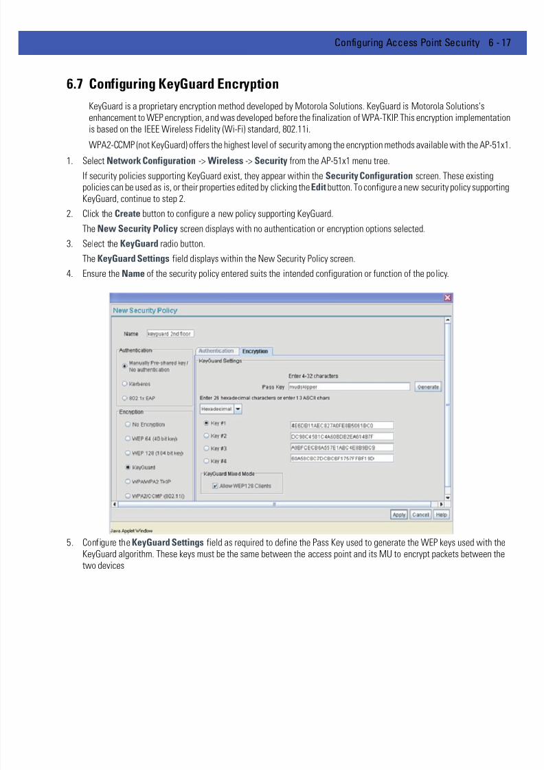
7/18/2019 Motorola AP 5131 Manual
http://slidepdf.com/reader/full/motorola-ap-5131-manual 193/613
Configuring Access Point Security 6 - 17
6.7 Configuring KeyGuard Encryption
KeyGuard is a proprietary encryption method developed by Motorola Solutions. KeyGuard is Motorola Solutions'senhancement to WEP encryption, and was developed before the finalization of WPA-TKIP. This encryption implementationis based on the IEEE Wireless Fidelity (Wi-Fi) standard, 802.11i.
WPA2-CCMP (not KeyGuard) offers the highest level of security among the encryption methods available with the AP-51x1
1. Select Network Configuration -> Wireless -> Security from the AP-51x1 menu tree.
If security policies supporting KeyGuard exist, they appear within the Security Configuration screen. These existingpolicies can be used as is, or their properties edited by clicking the Edit button. To configure a new security policy supportingKeyGuard, continue to step 2.
2. Click the Create button to configure a new policy supporting KeyGuard.
The New Security Policy screen displays with no authentication or encryption options selected.
3. Select the KeyGuard radio button.
The KeyGuard Settings field displays within the New Security Policy screen.
4. Ensure the Name of the security policy entered suits the intended configuration or function of the policy.
5. Configure the KeyGuard Settings field as required to define the Pass Key used to generate the WEP keys used with theKeyGuard algorithm. These keys must be the same between the access point and its MU to encrypt packets between thetwo devices

7/18/2019 Motorola AP 5131 Manual
http://slidepdf.com/reader/full/motorola-ap-5131-manual 194/613
6 - 18 WiNG 4.4 AP-5131 Product Reference Guide
Default (hexadecimal) keys for KeyGuard include:
6. Select the Allow WEP128 Clients checkbox (from within the KeyGuard Mixed Mode field) to enable WEP128 clients toassociate with an access point’s KeyGuard supported WLAN. The WEP128 clients must use the same keys as the KeyGuardclients to interoperate within the access point’s KeyGuard supported WLAN.
7. Click the Apply button to save any changes made within the KeyGuard Setting field of the New Security Policy screen.
8. Click the Cancel button to undo any changes made within the KeyGuard Setting field and return to the WLAN screen. Thisreverts all settings to the last saved configuration.
Pass Key Specify a 4 to 32 character pass key and click the Generate button.
The pass key can be any alphanumeric string. The AP-51x1, other
proprietary routers, and Motorola Solutions MUs use the algorithm
to convert an ASCII string to the same hexadecimal number. MUs
without Motorola Solutions adapters need to use WEP keysmanually configured as hexadecimal numbers.
Keys #1-4 Use the Key #1-4 areas to specify key numbers. The key can be
either a hexadecimal or ASCII depending on which option is
selected from the drop-down menu. The keys are 26 hexadecimal
characters in length or 13 ASCII characters. Select one of these
keys for activation by clicking its radio button.
Key 1 101112131415161718191A1B1C
Key 2 202122232425262728292A2B2C
Key 3 303132333435363738393A3B3C
Key 4 404142434445464748494A4B4C

7/18/2019 Motorola AP 5131 Manual
http://slidepdf.com/reader/full/motorola-ap-5131-manual 195/613
Configuring Access Point Security 6 - 19
6.8 Configuring WPA/WPA2 Using TKIP
Wi-Fi Protected Access (WPA) is a robust encryption scheme specified in the IEEE Wireless Fidelity (Wi-Fi) standard,802.11i. WPA provides more sophisticated data encryption than WEP. WPA is designed for corporate networks and smallbusiness environments where more wireless traffic allows quicker discovery of encryption keys by an unauthorized person
The encryption method is Temporal Key Integrity Protocol (TKIP). TKIP addresses WEP’s weaknesses with a re-keyingmechanism, a per-packet mixing function, a message integrity check, and an extended initialization vector.
Wi-Fi Protected Access 2 (WPA2) is an enhanced version of WPA. WPA2 uses the Advanced Encryption Standard (AES)instead of TKIP. AES supports 128-bit, 192-bit and 256-bit keys.
WPA/WPA2 also provide strong user authentication based on 802.1x EAP. To configure WPA/WPA2 encryption on theAP-51x1:
1. Select Network Configuration -> Wireless -> Security from the AP-51x1 menu tree.
If security policies supporting WPA-TKIP exist, they appear within the Security Configuration screen. These existingpolicies can be used as is, or their properties edited by clicking the Edit button. To configure a new security policy supporting
WPA-TKIP, continue to step 2.2. Click the Create button to configure a new policy supporting WPA-TKIP.
The New Security Policy screen displays with no authentication or encryption options selected.
3. Select the WPA/WPA2 TKIP radio button.
The WPA/TKIP Settings field displays within the New Security Policy screen.
4. Ensure the Name of the security policy entered suits the intended configuration or function of the policy.
5. Configure the Key Rotation Settings area as needed to broadcast encryption key changes to MUs and define the broadcastinterval.

7/18/2019 Motorola AP 5131 Manual
http://slidepdf.com/reader/full/motorola-ap-5131-manual 196/613
6 - 20 WiNG 4.4 AP-5131 Product Reference Guide
6. Configure the Key Settings area as needed to set an ASCII Passphrase and key values.
Default (hexadecimal) 256-bit keys for WPA/TKIP include:
1011121314151617
18191A1B1C1D1E1F
2021222324252627
28292A2B2C2D2E2F
7. Enable WPA2-TKIP Support as needed to allow WPA2 and TKIP client interoperation.
8. Configure the Fast Roaming (802.1x only) field as required to enable additional AP-51x1 roaming and key caching options.This feature is applicable only when using 802.1x EAP authentication with WPA2-TKIP.
Broadcast Key
Rotation
Select the Broadcast Key Rotation checkbox to enable or disable
broadcast key rotation. When enabled, the key indices used for
encrypting/decrypting broadcast traffic will be alternatively
rotated on every interval specified in the Broadcast Key Rotation
Interval. Enabling broadcast key rotation enhances the broadcasttraffic security on the WLAN. This value is disabled by default.
Update broadcast
keys every (300-
604800 seconds)
Specify a time period in seconds to rotate the key index used for the
broadcast key. Set the interval to a shorter duration like 3600
seconds for tighter broadcast traffic security on the wireless LAN.
Set the interval to a longer duration like 86400 seconds for less
broadcast traffic security requirements. Default value is 86400
secs.
ASCII Passphrase To use an ASCII passphrase (and not a hexadecimal value), select
the checkbox and enter an alphanumeric string of 8 to 63characters. The alphanumeric string allows character spaces. The
AP-51x1 converts the string to a numeric value. This passphrase
saves the administrator from entering the 256-bit key each time
keys are generated.
256-bit Key To use a hexadecimal value (and not an ASCII passphrase), select
the checkbox and enter 16 hexadecimal characters into each of the
four fields displayed.
Allow WPA2-TKIP
clients
WPA2-TKIP support enables WPA2 and TKIP clients to operate
together on the network.
Pre-Authentication Selecting this option enables an associated MU to carry out an
802.1x authentication with another AP-51x1 before it roams to it.The AP-51x1 caches the keying information of the client until it
roams to the other AP-51x1. This enables the roaming client to start
sending and receiving data sooner by not having to do 802.1x
authentication after it roams. This feature is only supported when
802.1x EAP authentication and WPA2-TKIP is enabled.
NOTE PMK key caching is enabled internally by default for WPA2-TKIP when802.1x EAP authentication is enabled.

7/18/2019 Motorola AP 5131 Manual
http://slidepdf.com/reader/full/motorola-ap-5131-manual 197/613
Configuring Access Point Security 6 - 21
9. Click the Apply button to save any changes made within this New Security Policy screen.
10. Click the Cancel button to undo any changes made within the WPA/TKIP Settings field and return to the WLAN screen.This reverts all settings to the last saved configuration.
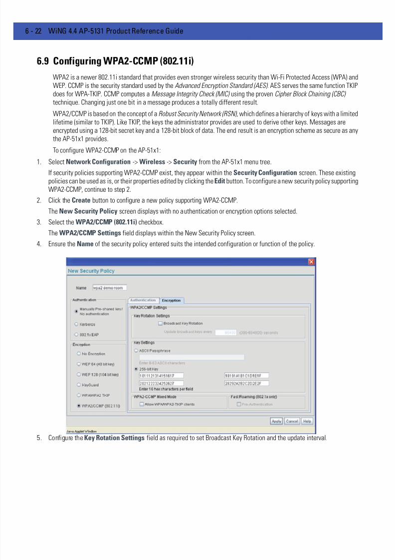
7/18/2019 Motorola AP 5131 Manual
http://slidepdf.com/reader/full/motorola-ap-5131-manual 198/613
6 - 22 WiNG 4.4 AP-5131 Product Reference Guide
6.9 Configuring WPA2-CCMP (802.11i)
WPA2 is a newer 802.11i standard that provides even stronger wireless security than Wi-Fi Protected Access (WPA) andWEP. CCMP is the security standard used by the Advanced Encryption Standard (AES). AES serves the same function TKIPdoes for WPA-TKIP. CCMP computes a Message Integrity Check (MIC) using the proven Cipher Block Chaining (CBC)technique. Changing just one bit in a message produces a totally different result.
WPA2/CCMP is based on the concept of a Robust Security Network (RSN), which defines a hierarchy of keys with a limitedlifetime (similar to TKIP). Like TKIP, the keys the administrator provides are used to derive other keys. Messages areencrypted using a 128-bit secret key and a 128-bit block of data. The end result is an encryption scheme as secure as anythe AP-51x1 provides.
To configure WPA2-CCMP on the AP-51x1:
1. Select Network Configuration -> Wireless -> Security from the AP-51x1 menu tree.
If security policies supporting WPA2-CCMP exist, they appear within the Security Configuration screen. These existingpolicies can be used as is, or their properties edited by clicking the Edit button. To configure a new security policy supportingWPA2-CCMP, continue to step 2.
2. Click the Create button to configure a new policy supporting WPA2-CCMP.
The New Security Policy screen displays with no authentication or encryption options selected.
3. Select the WPA2/CCMP (802.11i) checkbox.
The WPA2/CCMP Settings field displays within the New Security Policy screen.
4. Ensure the Name of the security policy entered suits the intended configuration or function of the policy.
5. Configure the Key Rotation Settings field as required to set Broadcast Key Rotation and the update interval.
7/18/2019 Motorola AP 5131 Manual
http://slidepdf.com/reader/full/motorola-ap-5131-manual 199/613
Configuring Access Point Security 6 - 23
6. Configure the Key Settings area as needed to set an ASCII Passphrase and 128-bit key.
Default (hexadecimal) 256-bit keys for WP2A/CCMP include:
1011121314151617
18191A1B1C1D1E1F
202122232425262728292A2B2C2D2E2F
7. Configure the WPA2-CCMP Mixed Mode field as needed to allow WPA and WPA2 TKIP client interoperation.
8. Configure the Fast Roaming (802.1x only) field as required to enable additional AP-51x1 roaming and key caching options.This feature is applicable only when using 802.1x EAP authentication with WPA2/CCMP.
Broadcast Key
Rotation
Select the Broadcast Key Rotation checkbox to enable or disable
broadcast key rotation. When enabled, the key indices used for
encrypting/decrypting broadcast traffic will be alternatively
rotated on every interval specified in the Broadcast Key Rotation
Interval. Enabling broadcast key rotation enhances the broadcasttraffic security on the WLAN. This value is disabled by default.
Update broadcast
keys every (300-
604800 seconds)
Specify a time period in seconds to rotate the key index used for the
broadcast key. Set the interval to a shorter duration like 3600
seconds for tighter broadcast traffic security on the wireless LAN.
Set the interval to a longer duration like 86400 seconds for less
broadcast traffic security requirements. Default value is 86400
secs.
ASCII Passphrase To use an ASCII passphrase (and not a hexadecimal value), select
the checkbox enter an alphanumeric string of 8 to 63 characters.The string allows character spaces. The AP-51x1 converts the
string to a numeric value. This passphrase saves the administrator
from entering the 256-bit key each time keys are generated.
256-bit Key To use a hexadecimal value (and not an ASCII passphrase), select
the checkbox and enter 16 hexadecimal characters into each of the
four fields displayed.
Allow
WPA/WPA2-TKIP
clients
WPA2-CCMP Mixed Mode enables WPA2-CCMP, WPA-TKIP and
WPA2-TKIP clients to operate together on the network. Enabling
this option allows backwards compatibility for clients that support
WPA-TKIP and WPA2-TKIP but do not support WPA2-CCMP.
Motorola Solutions recommends enabling this feature if WPA-TKIP
or
WPA2-TKIP supported MUs operate within a WLAN populated by
WPA2-CCMP enabled clients.
Pre-Authentication Selecting this option enables an associated MU to carry out an
802.1x authentication with another AP-51x1 before it roams to it.
The AP-51x1 caches the keying information of the client until it
roams to the other AP-51x1. This enables the roaming client to start
sending and receiving data sooner by not having to do 802.1x
authentication after it roams. This feature is only supported when
802.1x EAP authentication is enabled.

7/18/2019 Motorola AP 5131 Manual
http://slidepdf.com/reader/full/motorola-ap-5131-manual 200/613
6 - 24 WiNG 4.4 AP-5131 Product Reference Guide
9. Click the Apply button to save any changes made within this New Security Policy screen.
10. Click the Cancel button to undo any changes made within the WPA2/CCMP Settings field and return to the WLAN screen.This reverts all settings to the last saved configuration.
NOTE PMK key caching is enabled internally by default when 802.1x EAPauthentication is enabled.

7/18/2019 Motorola AP 5131 Manual
http://slidepdf.com/reader/full/motorola-ap-5131-manual 201/613
Configuring Access Point Security 6 - 25
6.10 Configuring Firewall Settings
The AP-51x1's firewall is a set of related programs located in the gateway on the WAN side of the AP-51x1. The firewalluses a collection of filters to screen information packets for known types of system attacks. Some of the AP-51x1's filtersare continuously enabled, others are configurable.
Use the AP-51x1’s Firewall screen to enable or disable the configurable firewall filters. Enable each filter for maximumsecurity. Disable a filter if the corresponding attack does not seem a threat in order to reduce processor overhead. Use theWLAN Security screens (WEP, Kerberos etc.) as required for setting user authentication and data encryption parameters.
To configure the AP-51x1 firewall settings:
1. Select Network Configuration -> Firewall from the AP-51x1 menu tree.
2. Refer to the Global Firewall Disable field to enable or disable the AP-51x1 firewall.
3. Refer to the Timeout Configuration field to define a timeout interval to terminate IP address translations.
4. Refer to the Configurable Firewall Filters field to set the following firewall filters:
Disable Firewall Select the Disable Firewall checkbox to disable all firewall
functions on the AP-51x1. This includes firewall filters, NAT, VP,
content filtering, and subnet access. Disabling the AP-51x1 firewall
makes the AP-51x1 vulnerable to data attacks and is not
recommended during normal operation if using the WAN port.
NAT Timeout Network Address Translation (NAT) converts an IP address in one
network to a different IP address or set of IP addresses in a
different network. Set a NAT Timeout interval (in minutes) the
AP-51x1 uses to terminate the IP address translation process if no
translation activity is detected after the specified interval.
7/18/2019 Motorola AP 5131 Manual
http://slidepdf.com/reader/full/motorola-ap-5131-manual 202/613
6 - 26 WiNG 4.4 AP-5131 Product Reference Guide
5. Click Apply to save any changes to the Firewall screen. Navigating away from the screen without clicking the Apply buttonresults in all changes to the screens being lost.
6. Click Undo Changes (if necessary) to undo any changes made. Undo Changes reverts the settings displayed on the Firewallscreen to the last saved configuration.
7. Click Logout to securely exit the Access Point applet. A prompt displays confirming the logout before the applet is closed.
6.10.1 Configuring LAN to WAN Access
The AP-51x1 LAN can be configured to communicate with the WAN side of the AP-51x1. Use the Subnet Access screento control access from the LAN1 (or LAN2) interfaces to the WAN interface. This access level will function as an ACL in arouter to allow/deny certain IP addresses or subnets to access certain interfaces (or subnets belonging to those interfaces)by creating access policies. It also functions as a filter to allow/deny access for certain protocols such as HTTP, Telnet, FTPetc.
To configure AP-51x1 subnet access:
1. Select Network Configuration -> Firewall -> Subnet Access from the AP-51x1 menu tree.
2. Refer to the Overview field to view rectangles representing subnet associations. The three possible colors indicate thecurrent access level, as defined, for each subnet association.
SYN Flood Attack
Check
A SYN flood attack requests a connection and then fails to
promptly acknowledge a destination host's response, leaving the
destination host vulnerable to a flood of connection requests.
Source RoutingCheck A source routing attack specifies an exact route for a packet'stravel through a network, while exploiting the use of an
intermediate host to gain access to a private host.
Winnuke Attack
Check
A "Win-nuking" attack uses the IP address of a destination host to
send junk packets to its receiving port.
FTP Bounce Attack
Check
An FTP bounce attack uses the PORT command in FTP mode to gain
access to arbitrary ports on machines other than the originating
client.
IP Unaligned
Timestamp Check
An IP unaligned timestamp attack uses a frame with the IP
timestamp option, where the timestamp is not aligned on a 32-bit
boundary.
Sequence NumberPrediction Check
A sequence number prediction attack establishes a three-way TCPconnection with a forged source address. The attacker guesses the
sequence number of the destination host response.
Mime Flood Attack
Check
A MIME flood attack uses an improperly formatted MIME header
in "sendmail" to cause a buffer overflow on the destination host.
Max Header Length
(>=256)
Use the Max Header Length field to set the maximum allowable
header length (at least 256 bytes).
Max Headers
(>=12)
Use the Max Headers field to set the maximum number of
headers allowed (at least 12 headers).

7/18/2019 Motorola AP 5131 Manual
http://slidepdf.com/reader/full/motorola-ap-5131-manual 203/613
Configuring Access Point Security 6 - 27
3. Configure the Rules field as required to allow or deny access to selected (enabled) protocols.
Color Access Type Description
Green Full Access No protocol exceptions (rules) are specified. All traffic may
pass between these two areas.
Yellow Limited Access One or more protocol rules are specified. Specific protocolsare either enabled or disabled between these two areas.
Click the table cell of interest and look at the exceptions
area in the lower half of the screen to determine the
protocols that are either allowed or denied.
Red No Access All protocols are denied, without exception. No traffic will
pass between these two areas.

7/18/2019 Motorola AP 5131 Manual
http://slidepdf.com/reader/full/motorola-ap-5131-manual 204/613
6 - 28 WiNG 4.4 AP-5131 Product Reference Guide
4. Click Apply to save any changes to the Subnet Access screen. Navigating away from the screen without clicking the Applybutton results in all changes to the screens being lost.
5. Click Undo Changes (if necessary) to undo any changes made. Undo Changes reverts the settings displayed on the SubnetAccess screen to the last saved configuration.
6. Click Logout to securely exit the Access Point applet. A prompt displays confirming the logout before the applet is closed.
Allow or Deny all
protocols, except
Use the drop-down menu to select either Allow or Deny. The
selected setting applies to all protocols except those with enabled
checkboxes and any traffic that is added to the table. For example,
if the adoption rule is to Deny access to all protocols except those
listed, access is allowed only to those selected protocols.
Pre configured Rules The following protocols are preconfigured with the AP-51x1. To
enable a protocol, check the box next to the protocol name.
• HTTP - Hypertext Transfer Protocol is the protocol for
transferring files on the Web. HTTP is an application protocol
running on top of the TCP/IP suite of protocols, the
foundation protocols for the Internet. The HTTP protocol uses
TCP port 80.
• TELNET - TELNET is the terminal emulation protocol of TCP/
IP. TELNET uses TCP to achieve a virtual connection between
server and client, then negotiates options on both sides of
the connection. TELNET uses TCP port 23.
• FTP - File Transfer Protocol (FTP) is an application protocol
using the Internet's TCP/IP protocols. FTP provides an
efficient way to exchange files between computers on the
Internet. FTP uses TCP port 21.
• SMTP - Simple Mail Transfer Protocol is a TCP/IP protocol for
sending and receiving email. Due to its limited ability to
queue messages at the receiving end, SMTP is often used
with POP3 or IMAP. SMTP sends the email, and POP3 or
IMAP receives the email. SMTP uses TCP port 25.
• POP - Post Office Protocol is a TCP/IP protocol intended to
permit a workstation to dynamically access a maildrop on a
server host. A workstation uses POP3 to retrieve email that
the server is holding for it.• DNS - Domain Name Service protocol searches for resources
using a database distributed among different name servers.
Add Click Add to create a new table entry.
Del (Delete) Click Del (Delete) to remove a selected list entry.
Name Specify a name for a newly configured protocol.
Transport Select a protocol from the drop-down menu. For a detailed
description of the protocols available, see Available Protocols on
page 6-29 .
Start Port Enter the starting port number for a range of ports. If the protocol
uses a single port, enter that port in this field.
End Port Enter the ending port number for a port range. If the protocol uses
a single port, leave the field blank. A new entry might use Web
Traffic for its name, TCP for its protocol, and 80 for its port number.

7/18/2019 Motorola AP 5131 Manual
http://slidepdf.com/reader/full/motorola-ap-5131-manual 205/613
Configuring Access Point Security 6 - 29
6.10.1.1 Available Protocols
Protocols that are not pre-configured can be specified using the drop down list within the Transport column within theSubnet Access and Advanced Subnet Access screens. They include:
• ALL - Enables all of the protocol options displayed in the drop-down menu (as described below).
• TCP - Transmission Control Protocol is a set of rules for sending data as message units over the Internet. TCP managesindividual data packets. Messages are divided into packets for efficient routing through the Internet.
• UDP - User Datagram Protocol is used for broadcasting data over the Internet. Like TCP, UDP runs on top of InternetProtocol (IP) networks. Unlike TCP/IP, UDP/IP provides few error recovery services. UDP offers a way to directly connect,and then send and receive datagrams over an IP network.
• ICMP - Internet Control Message Protocol is tightly integrated with IP. ICMP messages are used for out-of-bandmessages related to network operation. ICMP packet delivery is unreliable. Hosts cannot count on receiving ICMPpackets for a network problem.
• AH - Authentication Header is one of the two key components of IP Security Protocol (IPsec). The other key componentis Encapsulating Security Protocol (ESP) .
AH provides authentication, proving the packet sender really is the sender, and the data really is the data sent. AH can beused in transport mode, providing security between two end points. Also, AH can be used in tunnel mode, providing securitylike that of a Virtual Private Network (VPN).
• ESP - Encapsulating Security Protocol is one of two key components of IP Security Protocol (IPsec). The other keycomponent is Authentication Header (AH). ESP encrypts the packets and provides authentication services. ESP can beused in transport mode, providing security between two end points. ESP can also be used in tunnel mode, providingsecurity like that of a Virtual Private Network (VPN).
• GRE - General Routing Encapsulation supports VPNs across the Internet. GRE is a mechanism for encapsulatingnetwork layer protocols over any other network layer protocol. Such encapsulation allows routing of IP packetsbetween private IP networks across an Internet using globally assigned IP addresses.
6.10.2 Configuring Advanced Subnet Access
Use the Advanced Subnet Access screen to configure complex access rules and filtering based on source port,destination port, and transport protocol. To enable advanced subnet access, the subnet access rules must be overridden.However, the Advanced Subnet Access screen allows you to import existing subnet access rules into the advanced subnetaccess rules.
To configure AP-51x1 Advanced Subnet Access:
1. Select Network Configuration -> Firewall -> Advanced Subnet Access from the AP-51x1 menu tree.

7/18/2019 Motorola AP 5131 Manual
http://slidepdf.com/reader/full/motorola-ap-5131-manual 206/613
6 - 30 WiNG 4.4 AP-5131 Product Reference Guide
2. Configure the Settings field as needed to override the settings in the Subnet Access screen and import firewall rules intothe Advanced Subnet Access screen.
3. Configure the Firewall Rules field as required add, insert or delete firewall rules into the list of advanced rules.
Override Subnet
Access settings
Select this checkbox to enable advanced subnet access rules and
disable existing subnet access rules, port forwarding, and 1 to
many mappings from the system. Only enable advanced subnet
access rules if your configuration requires rules that cannot be
configured within the Subnet Access screen.Import rules from
Subnet Access
Select this checkbox to import existing access rules (NAT, packet
forwarding, VPN rules etc.) into the Firewall Rules field. This rule
import overrides any existing rules configured in the Advanced
Subnet Access screen. A warning box displays stating the
operation cannot be undone.
Inbound or Outbound Select Inbound or Outbound from the drop-down menu to specify
if a firewall rule is intended for inbound traffic to an interface or
outbound traffic from that interface.
Add Click the Add button to insert a new rule at the bottom of the table.Click on a row to display a new window with configuration options
for that field.
Insert Click the Insert button to insert a new rule directly above a
selected rule in the table. Clicking on a field in the row displays a
new window with configuration options.
Del (Delete) Click Del to remove the selected rule from the table. The index
numbers for all the rows below the deleted row decrease by 1.

7/18/2019 Motorola AP 5131 Manual
http://slidepdf.com/reader/full/motorola-ap-5131-manual 207/613
Configuring Access Point Security 6 - 31
4. Click Apply to save any changes to the Advanced Subnet Access screen. Navigating away from the screen without clickingApply results in all changes to the screens being lost.
5. Click Undo Changes (if necessary) to undo any changes made. Undo Changes reverts the settings displayed on theAdvanced Subnet Access screen to the last saved configuration.
6. Click Logout to securely exit the Access Point applet. A prompt displays confirming the logout before the applet is closed.
Move Up Clicking the Move Up button moves the selected rule up by one
row in the table. The index numbers for the affected rows adjust to
reflect the new order.
Move Down Clicking the Move Down button moves the selected rule down by
one row in the table. The index numbers for the affected rowsadjust to reflect the new order.
Index The index number determines the order firewall rules are executed.
Rules are executed from the lowest number to the highest number.
Source IP The Source IP range defines the origin address or address range
for the firewall rule. To configure the Source IP range, click on the
field. A new window displays for entering the IP address and range.
Destination IP The Destination IP range determines the target address or
address range for the firewall rule. To configure the Destination IP
range, click on the field. A new window displays for entering the IP
address and range.
Transport Select a protocol from the drop-down list. For a detailed descriptionof the protocols available, see Available Protocols on page 6-29 .
Src. Ports (Source
Ports)
The source port range determines which ports the firewall rule
applies to on the source IP address. Click on the field to configure
the source port range. A new window displays to enter the starting
and ending port ranges. For rules where only a single port is
necessary, enter the same port in the start and end port fields.
Dst. Ports (Destination
Ports
The destination port range determines which ports the firewall rule
applies to on the destination IP address. Click on the field to
configure the destination port range. A new window displays to
enter the starting and ending ports in the range. For rules where
only a single port is necessary, enter the same port in the start and
end port fields.

7/18/2019 Motorola AP 5131 Manual
http://slidepdf.com/reader/full/motorola-ap-5131-manual 208/613
6 - 32 WiNG 4.4 AP-5131 Product Reference Guide
6.11 Configuring VPN Tunnels
The AP-51x1 allows up to 25 VPN tunnels to either a VPN endpoint or to another AP-51x1. VPN tunnels allow all traffic ona local subnet to route securely through a IPSEC tunnel to a private network. A VPN port is a virtual port which handlestunneled traffic.
When connecting to another site using a VPN, the traffic is encrypted so if anyone intercepts the traffic, they cannot seewhat it is unless they can break the encryption. The traffic is encrypted from your computer through the network to theVPN. At that point the traffic is decrypted.
Use the VPN screen to add and remove VPN tunnels. To configure an existing VPN tunnel, select it from the list in the VPNTunnels field. The selected tunnel’s configuration displays in a VPN Tunnel Config field.
To configure a VPN tunnel on the AP-51x1:
1. Select Network Configuration -> WAN -> VPN from the AP-51x1 menu tree.
2. Use the VPN Tunnels field to add or delete a tunnel to the list of available tunnels, list tunnel network address informationand display key exchange information for each tunnel.
Add Click Add to add a VPN tunnel to the list. To configure a specific
tunnel, select it from the list and use the parameters within theVPN Tunnel Config field to set its properties.
Del Click Del to delete a highlighted VPN tunnel. There is no
confirmation before deleting the tunnel.
Tunnel Name The Tunnel Name column lists the name of each VPN tunnel on
the AP-51x1.
Remote Subnet The Remote Subnet column lists the remote subnet for each
tunnel. The remote subnet is the subnet the remote network uses
for connection.

7/18/2019 Motorola AP 5131 Manual
http://slidepdf.com/reader/full/motorola-ap-5131-manual 209/613
Configuring Access Point Security 6 - 33
If access point #1 has the following values:
• WAN IP address: 20.1.1.2• LAN IP address: 10.1.1.1
• Subnet Mask: 255.0.0.0
Then, the VPN values for access point #2 should be:
• Remote subnet: 10.1.1.0 or 10.0.0.0
• Remote subnet mask: 255.0.0.0
• Remote gateway: 20.1.1.2
3. If a VPN tunnel has been added to the list of available AP-51x1 tunnels, use the VPN Tunnel Config field to optionallymodify the tunnel’s properties.
Remote Gateway The Remote Gateway column lists a remote gateway IP address
for each tunnel. The numeric remote gateway is the gateway IP
address on the remote network the VPN tunnel connects to. Ensure
the address is the same as the WAN port address of the target
gateway AP or switch.
Key Exchange Type The Key Exchange Type column lists the key exchange type for
passing keys between both ends of a VPN tunnel. If Manual Key
Exchange is selected, this column displays Manual. If Auto (IKE)
Key Exchange is selected, the field displays Automatic.
NOTE When creating a tunnel, the remote subnet and remote subnet mask mustbe that of the target device’s LAN settings. The remote gateway must bethat of the target device’s WAN IP address.
Tunnel Name Enter a name to define the VPN tunnel. The tunnel name is used to
uniquely identify each tunnel. Select a name best suited to that
tunnel’s function so it can be selected again in the future if required
in a similar application.
Interface name Use the drop-down menu to specify the LAN1, LAN2 or WAN
connection used for routing VPN traffic. Remember, only one LAN
connection can be active on the access point Ethernet port at a
time. The LAN connection specified from the LAN screen to receive
priority for Ethernet port connectivity may be the better subnet to
select for VPN traffic.
Local WAN IP Enter the WAN’s numerical (non-DNS) IP address in order for the
tunnel to pass traffic to a remote network.
Remote Subnet Specify the numerical (non-DNS) IP address for the Remote Subnet.
Remote Subnet Mask Enter the subnet mask for the tunnel’s remote network for the
tunnel. The remote subnet mask is the subnet setting for the
remote network the tunnel connects to.
Remote Gateway Enter a numerical (non-DNS) remote gateway IP address for the
tunnel. The remote gateway IP address is the gateway address on
the remote network the VPN tunnel connects to.
Default Gateway Displays the WAN interface's default gateway IP address.
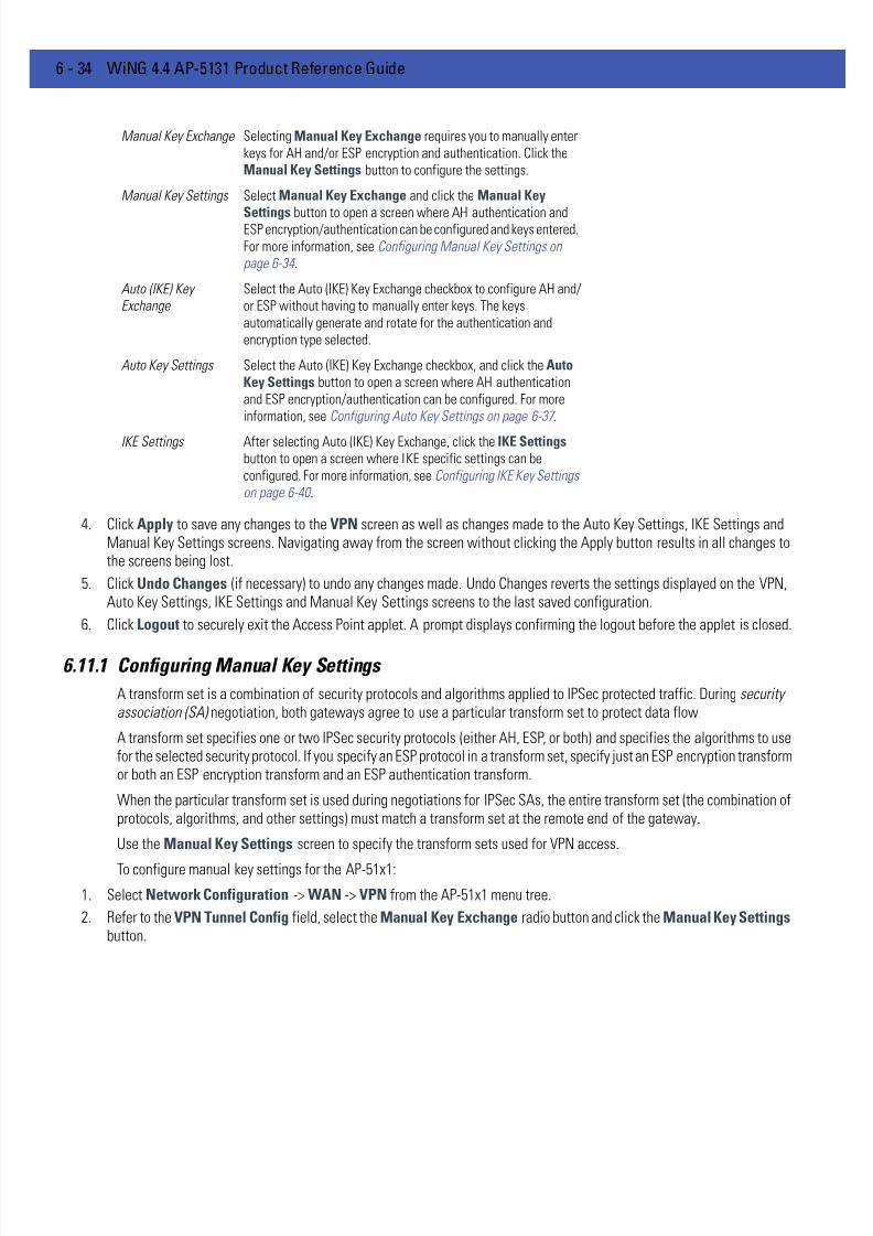
7/18/2019 Motorola AP 5131 Manual
http://slidepdf.com/reader/full/motorola-ap-5131-manual 210/613
6 - 34 WiNG 4.4 AP-5131 Product Reference Guide
4. Click Apply to save any changes to the VPN screen as well as changes made to the Auto Key Settings, IKE Settings andManual Key Settings screens. Navigating away from the screen without clicking the Apply button results in all changes tothe screens being lost.
5. Click Undo Changes (if necessary) to undo any changes made. Undo Changes reverts the settings displayed on the VPN,Auto Key Settings, IKE Settings and Manual Key Settings screens to the last saved configuration.
6. Click Logout to securely exit the Access Point applet. A prompt displays confirming the logout before the applet is closed.
6.11.1 Configuring Manual Key Settings
A transform set is a combination of security protocols and algorithms applied to IPSec protected traffic. During securityassociation (SA) negotiation, both gateways agree to use a particular transform set to protect data flow.
A transform set specifies one or two IPSec security protocols (either AH, ESP, or both) and specifies the algorithms to usefor the selected security protocol. If you specify an ESP protocol in a transform set, specify just an ESP encryption transformor both an ESP encryption transform and an ESP authentication transform.
When the particular transform set is used during negotiations for IPSec SAs, the entire transform set (the combination ofprotocols, algorithms, and other settings) must match a transform set at the remote end of the gateway.
Use the Manual Key Settings screen to specify the transform sets used for VPN access.
To configure manual key settings for the AP-51x1:
1. Select Network Configuration -> WAN -> VPN from the AP-51x1 menu tree.
2. Refer to the VPN Tunnel Config field, select the Manual Key Exchange radio button and click the Manual Key Settings button.
Manual Key Exchange Selecting Manual Key Exchange requires you to manually enter
keys for AH and/or ESP encryption and authentication. Click theManual Key Settings button to configure the settings.
Manual Key Settings Select Manual Key Exchange and click the Manual Key
Settings button to open a screen where AH authentication andESP encryption/authentication can be configured and keys entered.
For more information, see Configuring Manual Key Settings on
page 6-34 .
Auto (IKE) Key
Exchange
Select the Auto (IKE) Key Exchange checkbox to configure AH and/
or ESP without having to manually enter keys. The keys
automatically generate and rotate for the authentication and
encryption type selected.
Auto Key Settings Select the Auto (IKE) Key Exchange checkbox, and click the AutoKey Settings button to open a screen where AH authentication
and ESP encryption/authentication can be configured. For more
information, see Configuring Auto Key Settings on page 6-37 .
IKE Settings After selecting Auto (IKE) Key Exchange, click the IKE Settingsbutton to open a screen where IKE specific settings can be
configured. For more information, see Configuring IKE Key Settings
on page 6-40 .
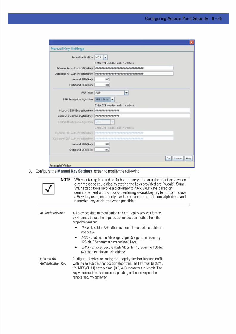
7/18/2019 Motorola AP 5131 Manual
http://slidepdf.com/reader/full/motorola-ap-5131-manual 211/613
Configuring Access Point Security 6 - 35
3. Configure the Manual Key Settings screen to modify the following:
NOTE When entering Inbound or Outbound encryption or authentication keys, anerror message could display stating the keys provided are “weak”. SomeWEP attack tools invoke a dictionary to hack WEP keys based oncommonly used words. To avoid entering a weak key, try to not to producea WEP key using commonly used terms and attempt to mix alphabetic andnumerical key attributes when possible.
AH Authentication AH provides data authentication and anti-replay services for the
VPN tunnel. Select the required authentication method from the
drop-down menu:
• None - Disables AH authentication. The rest of the fields are
not active.• MD5 - Enables the Message Digest 5 algorithm requiring
128-bit (32-character hexadecimal) keys.
• SHA1 - Enables Secure Hash Algorithm 1, requiring 160-bit
(40-character hexadecimal) keys.
Inbound AH
Authentication Key
Configure a key for computing the integrity check on inbound traffic
with the selected authentication algorithm. The key must be 32/40
(for MD5/SHA1) hexadecimal (0-9, A-F) characters in length. The
key value must match the corresponding outbound key on the
remote security gateway.

7/18/2019 Motorola AP 5131 Manual
http://slidepdf.com/reader/full/motorola-ap-5131-manual 212/613
6 - 36 WiNG 4.4 AP-5131 Product Reference Guide
Outbound AH
Authentication Key
Configure a key for computing the integrity check on outbound
traffic with the selected authentication algorithm. The key must be
32/40 (for MD5/SHA1) hexadecimal (0-9, A-F) characters in length.
The key value must match the corresponding inbound key on the
remote security gateway.
Inbound SPI (Hex) Enter an up to six-character hexadecimal value to identify the
inbound security association created by the AH algorithm. The
value must match the corresponding outbound SPI value configured
on the remote security gateway.
Outbound SPI (Hex) Provide an up to six-character hexadecimal value to identify the
outbound security association created by the AH algorithm. The
value must match the corresponding inbound SPI value configured
on the remote security gateway.
ESP Type ESP provides packet encryption, optional data authentication and
anti-replay services for the VPN tunnel. Use the drop-down menu
to select the ESP type. Options include:
• None - Disables ESP. The rest of the fields are not be active.
• ESP - Enables ESP for the tunnel.
• ESP with Authentication - Enables ESP with authentication.
ESP Encryption
Algorithm
Select the encryption and authentication algorithms for the VPN
tunnel using the drop-down menu.
• DES - Uses the DES encryption algorithm requiring 64-bit
(16-character hexadecimal) keys.
• 3DES - Uses the 3DES encryption algorithm requiring 192-bit
(48-character hexadecimal) keys.
• AES 128-bit : - Uses the Advanced Encryption Standard
algorithm with 128-bit (32-character hexadecimal) keys.
• AES 192-bit : - Uses the Advanced Encryption Standardalgorithm with 192-bit (48-character hexadecimal) keys.
• AES 256-bit : - Uses the Advanced Encryption Standard
algorithm with 256-bit (64-character hexadecimal) keys.
Inbound ESP
Encryption Key
Enter a key for inbound traffic. The length of the key is determined
by the selected encryption algorithm. The key must match the
outbound key at the remote gateway.
Outbound ESP
Encryption Key
Define a key for outbound traffic. The length of the key is
determined by the selected encryption algorithm. The key must
match the inbound key at the remote gateway.
ESP Authentication
Algorithm
Select the authentication algorithm to use with ESP. This option is
available only when ESP with Authentication was selected forthe ESP type. Options include:
• MD5 - Enables the Message Digest 5 algorithm, which
requires 128-bit (32-character hexadecimal) keys.
• SHA1 - Enables Secure Hash Algorithm 1, which requires
160-bit (40-character hexadecimal) keys.
Inbound ESP
Authentication Key
Define a key for computing the integrity check on the inbound
traffic with the selected authentication algorithm. The key must be
32/40 (for MD5/SHA1) hexadecimal (0-9, A-F) characters in length.
The key must match the corresponding outbound key on the remote
security gateway.

7/18/2019 Motorola AP 5131 Manual
http://slidepdf.com/reader/full/motorola-ap-5131-manual 213/613
Configuring Access Point Security 6 - 37
The Inbound and Outbound SPI settings are required to be interpolated to function correctly. For example:
• AP1 Inbound SPI = 800
• AP1 Outbound SPI = 801
• AP2 Inbound SPI = 801
• AP2 Outbound SPI = 800
4. Click Ok to return to the VPN screen. Click Apply to retain the settings made on the Manual Key Settings screen.
5. Click Cancel to return to the VPN screen without retaining the changes made to the Manual Key Settings screen.
6.11.2 Configuring Auto Key Settings
The AP-51x1’s Network Management System can automatically set encryption and authentication keys for VPN access.Use the Auto Key Settings screen to specify the type of encryption and authentication, without specifying the keys. To
manually specify keys, cancel out of the Auto Key Settings screen, select the Manual Key Exchange radio button, andset the keys within the Manual Key Setting screen.
To configure auto key settings for the AP-51x1:
1. Select Network Configuration -> WAN -> VPN from the AP-51x1 menu tree.
2. Refer to the VPN Tunnel Config field, select the Auto (IKE) Key Exchange radio button and click the Auto Key Settingsbutton.
Outbound ESP
Authentication Key
Enter a key for computing the integrity check on outbound traffic
with the selected authentication algorithm. The key must be 32/40
(for MD5/SHA1) hexadecimal (0-9, A-F) characters in length. The
key must match the corresponding inbound key on the remote
security gateway.
Inbound SPI (Hex) Define an (up to) six-character (maximum) hexadecimal value to
identify the inbound security association created by the encryption
algorithm. The value must match the corresponding outbound SPI
value configured on the remote security gateway.
Outbound SPI (Hex) Enter an (up to) six-character (maximum) hexadecimal value to
identify the outbound security association created by the
encryption algorithm. The value must match the corresponding
inbound SPI value configured on the remote security gateway.
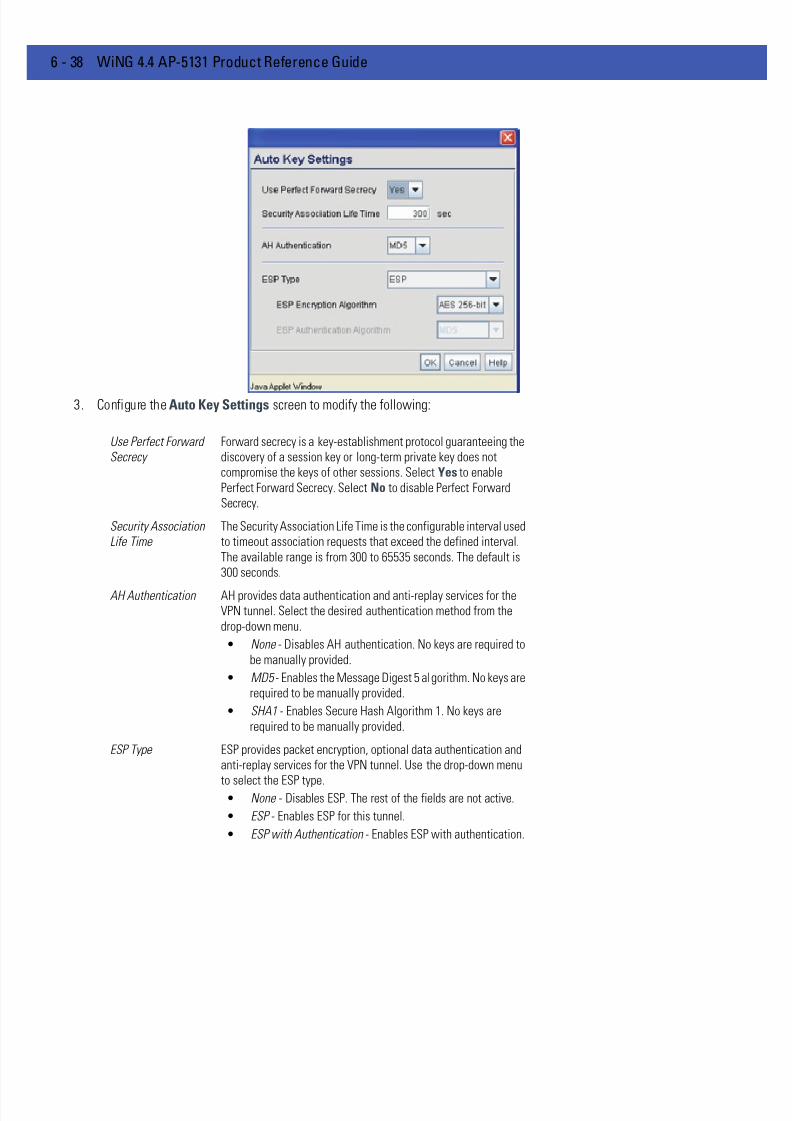
7/18/2019 Motorola AP 5131 Manual
http://slidepdf.com/reader/full/motorola-ap-5131-manual 214/613
6 - 38 WiNG 4.4 AP-5131 Product Reference Guide
3. Configure the Auto Key Settings screen to modify the following:
Use Perfect Forward
Secrecy
Forward secrecy is a key-establishment protocol guaranteeing the
discovery of a session key or long-term private key does not
compromise the keys of other sessions. Select Yes to enable
Perfect Forward Secrecy. Select No to disable Perfect Forward
Secrecy.
Security Association
Life Time
The Security Association Life Time is the configurable interval used
to timeout association requests that exceed the defined interval.
The available range is from 300 to 65535 seconds. The default is
300 seconds.
AH Authentication AH provides data authentication and anti-replay services for the
VPN tunnel. Select the desired authentication method from the
drop-down menu.
• None - Disables AH authentication. No keys are required to
be manually provided.
• MD5 - Enables the Message Digest 5 algorithm. No keys are
required to be manually provided.
• SHA1 - Enables Secure Hash Algorithm 1. No keys are
required to be manually provided.
ESP Type ESP provides packet encryption, optional data authentication and
anti-replay services for the VPN tunnel. Use the drop-down menu
to select the ESP type.• None - Disables ESP. The rest of the fields are not active.
• ESP - Enables ESP for this tunnel.
• ESP with Authentication - Enables ESP with authentication.
7/18/2019 Motorola AP 5131 Manual
http://slidepdf.com/reader/full/motorola-ap-5131-manual 215/613
Configuring Access Point Security 6 - 39
4. Click Ok to return to the VPN screen. Click Apply to retain the settings made on the Auto Key Settings screen.
5. Click Cancel to return to the VPN screen without retaining the changes made to this screen.
ESP Encryption
Algorithm
Use this menu to select the encryption and authentication
algorithms for this VPN tunnel.
• DES - Selects the DES algorithm.No keys are required to be
manually provided.
• 3DES - Selects the 3DES algorithm. No keys are required tobe manually provided.
• AES 128-bit: - Selects the Advanced Encryption Standard
algorithm with 128-bit. No keys are required to be manually
provided.
• AES 192-bit: - Selects the Advanced Encryption Standard
algorithm with 192-bit. No keys are required to be manually
provided.
• AES 256-bit : - Selects the Advanced Encryption Standard
algorithm with 256-bit. No keys are required to be manually
provided.
ESP Authentication
Algorithm
Use this menu to select the authentication algorithm to be used
with ESP. This menu is only active when ESP with Authenticationwas selected for the ESP type.
• MD5 - Enables the Message Digest 5 algorithm requiring
128-bit. No keys are required to be manually provided.
• SHA1 - Enables Secure Hash Algorithm. No keys are
required to be manually provided.

7/18/2019 Motorola AP 5131 Manual
http://slidepdf.com/reader/full/motorola-ap-5131-manual 216/613
6 - 40 WiNG 4.4 AP-5131 Product Reference Guide
6.11.3 Configuring IKE Key Settings
The Internet Key Exchange (IKE) is an IPsec standard protocol used to ensure security for VPN negotiation and remote hostor network access. IKE provides an automatic means of negotiation and authentication for communication between twoor more parties. In essence, IKE manages IPSec keys automatically for the parties.
To configure IKE key settings for the AP-51x1:
1. Select Network Configuration -> WAN -> VPN from the AP-51x1 menu tree.
2. Refer to the VPN Tunnel Config field, select the Auto (IKE) Key Exchange radio button and click the IKE Settings button.
3. Configure the IKE Key Settings screen to modify the following:

7/18/2019 Motorola AP 5131 Manual
http://slidepdf.com/reader/full/motorola-ap-5131-manual 217/613
Configuring Access Point Security 6 - 41
Operation Mode The Phase I protocols of IKE are based on the ISAKMP identity-
protection and aggressive exchanges. IKE main mode refers to the
identity-protection exchange, and IKE aggressive mode refers to
the aggressive exchange.
• Main - Standard IKE mode for communication and keyexchange.
• Aggressive - Aggressive mode is faster, but less secure than
Main mode. Identities are not encrypted unless public key
encryption is used. The authentication method cannot be
negotiated if the initiator chooses public key encryption
Local ID Type Select the type of ID to be used for the AP-51x1 end of the SA.
• IP - Select IP if the local ID type is the IP address specified
as part of the tunnel.
• FQDN - Use FQDN if the local ID is a fully qualified domain
name (such as sj.motorola.com).
• UFQDN - Select UFQDN if the local ID is a user fully-qualifiedemail (such as [email protected]).
Local ID Data Specify the FQDN or UFQDN based on the Local ID type assigned.
Remote ID Type Select the type of ID to be used for the AP-51x1 end of the tunnel
from the Remote ID Type drop-down menu.
• IP - Select the IP option if the remote ID type is the IP address
specified as part of the tunnel.
• FQDN - Select FQDN if the remote ID type is a fully qualified
domain name (such as sj.motorola.com). The setting for this
field does not have to be fully qualified, however it must
match the setting for the Certificate Authority.
• UFQDN - Select this item if the remote ID type is a user
unqualified email address (such as [email protected]).
The setting for this field does not have to be unqualified, it
just must match the setting of the field of the Certificate
Authority.
Remote ID Data If FQDN or UFQDN is selected, specify the data (either the qualified
domain name or the user name) in the Remote ID Data field.
IKE Authentication
Mode
Select the appropriate IKE authentication mode:
• Pre-Shared Key (PSK) - Specify an authenticating algorithm
and passcode used during authentication.
• RSA Certificates - Select this option to use RSA certificates
for authentication purposes. See the CA Certificates and Self
certificates screens to create and import certificates into thesystem.
IKE Authentication
Algorithm
IKE provides data authentication and anti-replay services for the
VPN tunnel. Select an authentication methods from the drop-down
menu.
• MD5 - Enables the Message Digest 5 algorithm. No keys are
required to be manually provided.
• SHA1 - Enables Secure Hash Algorithm. No keys are
required to be manually provided.

7/18/2019 Motorola AP 5131 Manual
http://slidepdf.com/reader/full/motorola-ap-5131-manual 218/613
6 - 42 WiNG 4.4 AP-5131 Product Reference Guide
4. Click Ok to return to the VPN screen. Click Apply to retain the settings made on the IKE Settings screen.
5. Click Cancel to return to the VPN screen without retaining the changes made to the IKE Settings screen.
6.11.4 Viewing VPN Status
Use the VPN Status screen to display the status of the tunnels configured on the AP-51x1 as well as their lifetime,transmit and receive statistics. The VPN Status screen is read-only with no configurable parameters. To configure a VPNtunnel, use the VPN configuration screen in the WAN section of the AP-51x1 menu tree.
To view VPN status:
1. Select Network Configuration -> WAN -> VPN -> VPN Status from the AP-51x1 menu tree.
IKE Authentication
Passphrase
If you selected Pre-Shared Key as the authentication mode, you
must provide a passphrase.
IKE Encryption
Algorithm
Select the encryption and authentication algorithms for the VPN
tunnel from the drop-down menu.
• DES - Uses the DES encryption algorithm. No keys arerequired to be manually provided.
• 3DES - Enables the 3DES encryption algorithm. No keys are
required to be manually provided.
• AES 128-bit - Uses the Advanced Encryption Standard
algorithm with 128-bit. No keys are required to be manually
provided.
• AES 192-bit - Enables the Advanced Encryption Standard
algorithm with 192-bit. No keys are required to be manually
provided.
• AES 256-bit - Uses the Advanced Encryption Standard
algorithm with 256-bit. No keys are required to be manually
provided.
Key Lifetime The number of seconds the key is valid. At the end of the lifetime,
the key is renegotiated.
The AP-51x1 forces renegotiation every 3600 seconds. There is no
way to change the renegotiation value. If the IKE Lifetime is greater
than 3600, the keys still get renegotiated every 3600 seconds.
Diffie Hellman Group Select a Diffie-Hellman Group to use. The Diffie-Hellman key
agreement protocol allows two users to exchange a secret key over
an insecure medium without any prior secrets. Two algorithms
exist, 768-bit and 1024-bit. Select one of the following options:
• Group 1 - 768 bit - Somewhat faster than the 1024-bit
algorithm, but secure enough in most situations.
• Group 2 - 1024 bit - Somewhat slower than the 768-bit
algorithm, but much more secure and a better choice for
extremely sensitive situations.
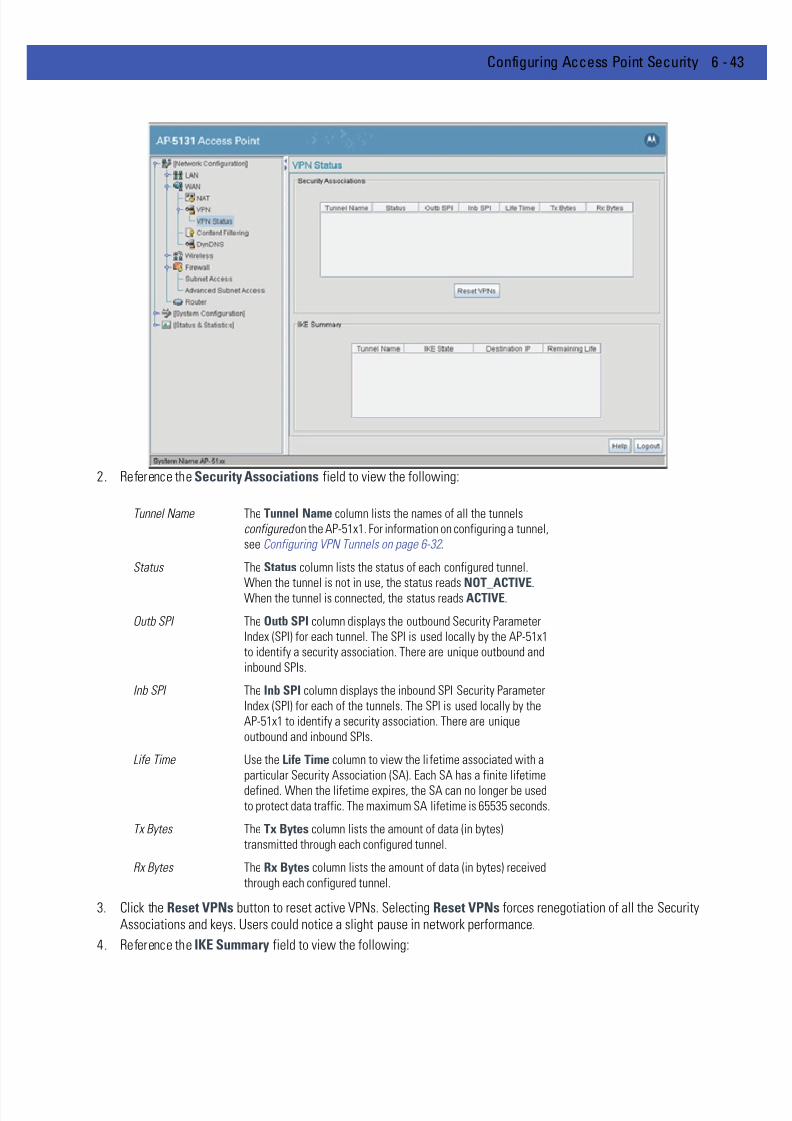
7/18/2019 Motorola AP 5131 Manual
http://slidepdf.com/reader/full/motorola-ap-5131-manual 219/613
Configuring Access Point Security 6 - 43
2. Reference the Security Associations field to view the following:
3. Click the Reset VPNs button to reset active VPNs. Selecting Reset VPNs forces renegotiation of all the SecurityAssociations and keys. Users could notice a slight pause in network performance.
4. Reference the IKE Summary field to view the following:
Tunnel Name The Tunnel Name column lists the names of all the tunnels
configured on the AP-51x1. For information on configuring a tunnel,
see Configuring VPN Tunnels on page 6-32 .
Status The Status column lists the status of each configured tunnel.
When the tunnel is not in use, the status reads NOT_ACTIVE.When the tunnel is connected, the status reads ACTIVE.
Outb SPI The Outb SPI column displays the outbound Security Parameter
Index (SPI) for each tunnel. The SPI is used locally by the AP-51x1
to identify a security association. There are unique outbound and
inbound SPIs.
Inb SPI The Inb SPI column displays the inbound SPI Security Parameter
Index (SPI) for each of the tunnels. The SPI is used locally by the
AP-51x1 to identify a security association. There are unique
outbound and inbound SPIs.
Life Time Use the Life Time column to view the lifetime associated with a
particular Security Association (SA). Each SA has a finite lifetime
defined. When the lifetime expires, the SA can no longer be used
to protect data traffic. The maximum SA lifetime is 65535 seconds.
Tx Bytes The Tx Bytes column lists the amount of data (in bytes)
transmitted through each configured tunnel.
Rx Bytes The Rx Bytes column lists the amount of data (in bytes) received
through each configured tunnel.

7/18/2019 Motorola AP 5131 Manual
http://slidepdf.com/reader/full/motorola-ap-5131-manual 220/613
6 - 44 WiNG 4.4 AP-5131 Product Reference Guide
5. Click Logout to securely exit the access point applet. A prompt displays confirming the logout before the applet is closed.
Tunnel Name Displays the name of each of the tunnels configured to use IKE for
automatic key exchange.
IKE State Lists the state for each of the tunnels configured to use IKE for
automatic key exchange. When the tunnel is not active, the IKEState field displays NOT_CONNECTED. When the tunnel is
active, the IKE State field displays CONNECTED.
Destination IP Displays the destination IP address for each tunnel configured to
use IKE for automatic key exchange.
Remaining Life Lists the remaining life of the current IKE key for each tunnel. When
the remaining life on the IKE key reaches 0, IKE initiates a
negotiation for a new key. IKE keys associated with a renegotiated
tunnel.

7/18/2019 Motorola AP 5131 Manual
http://slidepdf.com/reader/full/motorola-ap-5131-manual 221/613
Configuring Access Point Security 6 - 45
6.12 Configuring Content Filtering Settings
Content filtering allows system administrators to block specific commands and URL extensions from going out through theaccess point’s WAN port. Therefore, content filtering affords system administrators selective control on the contentproliferating the network and is a powerful data and network screening tool. Content filtering allows the blocking of up to10 files or URL extensions and allows blocking of specific outbound HTTP, SMTP, and FTP requests.
To configure content filtering for the AP-51x1:
1. Select Network Configuration -> WAN -> Content Filtering from the AP-51x1 menu tree.
2. Configure the HTTP field to configure block Web proxies and URL extensions.
3. Configure the SMTP field to disable or restrict specific kinds of network mail traffic.
Block Outbound HTTP HyperText Transport Protocol (HTTP) is the protocol used to transfer
information to and from Web sites. HTTP Blocking allows for
blocking of specific HTTP commands going outbound on the
AP-51x1 WAN port. HTTP blocks commands on port 80 only.
The Block Outbound HTTP option allows blocking of the following
(user selectable) outgoing HTTP requests:
• Web Proxy - Blocks the use of Web proxies by clients
• ActiveX - Blocks all outgoing ActiveX requests by clients.
Selecting ActiveX only blocks traffic (scripting language)
with an .ocx extension.
Block Outbound URL
Extensions
Enter a URL extension or file name per line in the format of
filename.ext . An asterisk (*) can be used as a wildcard in place of
the filename to block all files with a specific extension.

7/18/2019 Motorola AP 5131 Manual
http://slidepdf.com/reader/full/motorola-ap-5131-manual 222/613
6 - 46 WiNG 4.4 AP-5131 Product Reference Guide
4. Configure the FTP field to block or restrict various FTP traffic on the network.
Block Outbound SMTP
Commands
Simple Mail Transport Protocol (SMTP) is the Internet standard for
host-to-host mail transport. SMTP generally operates over TCP on
port 25. SMTP filtering allows the blocking of any or all outgoing
SMTP commands. Check the box next to the command to disable
that command when using SMTP across the AP-51x1’s WAN port.• HELO - (Hello) Identifies the SMTP sender to the SMTP
receiver.
• MAIL- Initiates a mail transaction where data is delivered to
one or more mailboxes on the local server.
• RCPT - (Recipient) Identifies a recipient of mail data.
• DATA - Tells the SMTP receiver to treat the following
information as mail data from the sender.
• QUIT - Tells the receiver to respond with an OK reply and
terminate communication with the sender.
• SEND - Initiates a mail transaction where mail is sent to one
or more remote terminals.
• SAML - (Send and Mail) Initiates a transaction where mail
data is sent to one or more local mailboxes and remote
terminals.
• RESET - Cancels mail transaction and informs the recipient
to discard data sent during transaction.
• VRFY - Asks receiver to confirm the specified argument
identifies a user. If argument does identify a user, the full
name and qualified mailbox is returned.
• EXPN - (Expand) Asks receiver to confirm a specified
argument identifies a mailing list. If the argument identifies
a list, the membership list of the mailing list is returned.
Block Outbound FTP
Actions
File Transfer Protocol (FTP) is the Internet standard for host-to-host
mail transport. FTP generally operates over TCP port 20 and 21. FTP
filtering allows the blocking of any or all outgoing FTP functions.
Check the box next to the command to disable the command when
using FTP across the AP-51x1’s WAN port.
• Storing Files - Blocks the request to transfer files sent from
the client across the AP’s WAN port to the FTP server.
• Retrieving Files - Blocks the request to retrieve files sent
from the FTP server across the AP’s WAN port to the client.
• Directory List - Blocks requests to retrieve a directory listing
sent from the client across the AP’s WAN port to the FTP
server.
• Create Directory - Blocks requests to create directories sent
from the client across the AP’s WAN port to the FTP server.
• Change Directory - Blocks requests to change directories
sent from the client across the AP's WAN port to the FTP
server.
• Passive Operation - Blocks passive mode FTP requests sent
from the client across the AP's WAN port to the FTP server.

7/18/2019 Motorola AP 5131 Manual
http://slidepdf.com/reader/full/motorola-ap-5131-manual 223/613
Configuring Access Point Security 6 - 47
5. Click Apply to save any changes to the Content Filtering screen. Navigating away from the screen without clicking the Applybutton results in all changes to the screens being lost.
6. Click Undo Changes (if necessary) to undo any changes made. Undo Changes reverts the settings displayed on the ContentFiltering screen to the last saved configuration.
7. Click Logout to securely exit the Access Point applet. A prompt displays confirming the logout before the applet is closed.

7/18/2019 Motorola AP 5131 Manual
http://slidepdf.com/reader/full/motorola-ap-5131-manual 224/613
6 - 48 WiNG 4.4 AP-5131 Product Reference Guide
6.13 Configuring Rogue AP Detection
It is possible that not all of the devices identified by the AP-51x1 are operating legitimately within the AP-51x1’s radiocoverage area. A rogue AP is a device located nearby an authorized Motorola Solutions AP-51x1 but recognized as havingproperties rendering its operation illegal and threatening to the AP-51x1 and the LAN. Rogue AP detection can beconfigured independently for both AP-51x1 802.11a and 802.11b/g radios (if using a dual radio sku AP-51x1). A roguedetection interval is the user-defined interval the AP-51x1 waits to search for rogue APs. Additionally, the access pointdoes not detect rogue APs on illegal channels (channels not allowed by the regulatory requirements of the country theaccess point is operating in).
The rogue detection interval is used in conjunction with Motorola Solutions MUs that identify themselves as roguedetection capable to the access point. The detection interval defines how often the access point requests these MUs toscan for a rogue AP. A shorter interval can affect the performance of the MU, but it will also decrease the time it takes forthe access point to scan for a rogue AP. A longer interval will have less of an impact to the MU’s, but it will increase theamount of time used to detect rogue APs. Therefore, the interval should be set according to the perceived risk of roguedevices and the criticality of MU performance.
To configure Rogue AP detection for the AP-51x1:
1. Select Network Configuration -> Wireless -> Rogue AP Detection from the AP-51x1 menu tree.
2. Configure the Detection Method field to set the detection method (MU or AP-51x1) and define the 802.11a or 802.11b/gradio to conduct the rogue AP search.
CAUTION Using an antenna other than the Dual-Band Antenna (Part No.ML-2452-APA2-01) could render the AP-51x1’s Rogue AP DetectorMode feature inoperable. Contact your Motorola Solutions salesassociate for specific information.

7/18/2019 Motorola AP 5131 Manual
http://slidepdf.com/reader/full/motorola-ap-5131-manual 225/613
Configuring Access Point Security 6 - 49
3. Use the Allowed AP List field to restrict Motorola Solutions AP’s from Rogue AP detection and create a list of device MAC
addresses and ESSID’s approved for interoperability with the AP-51x1.
RF Scan by MU Select the RF Scan by MU checkbox to enable MUs to scan for
potential rogue APs within the network. Define an interval in the
Scan Interval field for associated MUs to beacon in an attempt to
locate a rogue AP. Set the interval to a value sooner than the
default if a large volume of device network traffic is anticipatedwithin the coverage area of the target AP-51x1. The Scan Interval
field is not available unless the RF Scan by MU checkbox is
selected. Motorola Solutions clients must be associated and have
rogue AP detection enabled.
RF On-Channel
Detection
Select the RF On-Channel Detection checkbox to enable the
access point to detect rogue APs on its current (legal) channel
setting.
RF Scan by Detector
Radio
If the access point is a dual-radio model, select the RF Scan byDetector Radio checkbox to enable the selected 11a or 11b/g
radio to scan for rogue APs. For example, if 11b/g is selected, the
existing 11a radio would act as the “detector radio,” scanning on
all 11b/g channels while the existing 11b/g radio continues to
service MUs. The assumption is, when planning to do an all
channel scan on one band, the MUs would also be on that band.
The radio on the other band is used as the “detector radio.”
RF A/BG Scan Select this checkbox to scan for rouges over all channels on both of
the access point’s 11a and 11bg radio bands. The switching of radio
bands is based on a timer with no user intervention required. This
option provides a good opportunity to detect rogues, as rogues
often roam from one association to a stronger one regardless of the
current operating channel.
Authorize Any AP
Having Motorola
Defined MAC Address
Select this checkbox to enable all access points with a Motorola
Solutions MAC address to interoperate with the AP-51x1
conducting a scan for rogue devices.
Add Click Add to display a single set of editable MAC address and ESS
address values.
Del (Delete) Click the Delete button to remove the highlighted line from the
Rule Management field. The MAC and ESS address information
previously defined is no longer applicable unless the previous
configuration is restored.
Delete All Click the Delete All button to remove all entries from the RuleManagement field. All MAC and ESS address information
previously defined is no longer applicable unless the previous
configuration is restored.
Any MAC Select the Any MAC checkbox to prevent a device’s MAC address
(whether it is a known device MAC address or not) from being
considered a rogue device.
MAC Address Click Add, and enter the device MAC address to be excluded from
classification as a rogue device.

7/18/2019 Motorola AP 5131 Manual
http://slidepdf.com/reader/full/motorola-ap-5131-manual 226/613
6 - 50 WiNG 4.4 AP-5131 Product Reference Guide
4. Click Apply to save any changes to the Rogue AP Detection screen. Navigating away from the screen without clicking Applyresults in all changes to the screens being lost.
5. Click Undo Changes (if necessary) to undo any changes made. Undo Changes reverts the settings displayed on the RogueAP Detection screen to the last saved configuration.
6. Click Logout to securely exit the Access Point applet. A prompt displays confirming the logout before the applet is closed.
6.13.1 Moving Rogue APs to the Allowed AP List
The Active APs screen enables the user to view the list of detected rogue APs and, if necessary, select and move an APinto a list of allowed devices. This is helpful when the settings defined within the Rogue AP Detection screen
inadvertently detect and define a device as a rogue AP.
To move detected rogue APs into a list of allowed APs:
1. Select Network Configuration -> Wireless -> Rogue AP Detection -> Active APs from the AP-51x1 menu tree.
The Active APs screen displays with detected rogue devices displayed within the Rogue APs table.
2. Enter a value (in minutes) in the Allowed APs Age Out Time field to indicate the number of elapsed minutes before an APwill be removed from the approved list and reevaluated. A zero (0) for this value (default value) indicates an AP can remainon the approved AP list permanently.
3. Enter a value (in minutes) in the Rogue APs Age Out Time field to indicate the number of elapsed minutes before an AP willbe removed from the rogue AP list and reevaluated. A zero (0) for this value (default value) indicates an AP can remain onthe rogue AP list permanently.
Any ESSID Select the Any ESSid checkbox to prevent a device’s ESSID
(whether it is a known device ESSID or not) from being considered
a rogue device
ESSID Click Add, and enter the name of a device ESSid to be excluded
from classification as a rogue device.

7/18/2019 Motorola AP 5131 Manual
http://slidepdf.com/reader/full/motorola-ap-5131-manual 227/613
Configuring Access Point Security 6 - 51
4. Highlight an AP from within the Rogue APs table and click the Add to Allowed APs List button to move the device into thelist of Allowed APs.
5. Click the Add All to Allowed APs List button to move each of the APs displayed within the Rogue APs table to the list ofallowed APs.
6. Highlight a rogue AP and click the Details button to display a screen with device and detection information specific to thatrogue device. This information is helpful in determining if a rogue AP should be moved to the Allowed APs table.
For more information on the displaying information on detected rogue APs, see Displaying Rogue AP Details on page 6-51.
7. To remove the Rogue AP entries displayed within the e Rogue APs field, click the Clear Rogue AP List button.
Motorola Solutions only recommends clearing the list of Rogue APs when the devices displaying within the list do notrepresent a threat to the access point managed network.
8. Click Apply to save any changes to the Active APs screen. Navigating away from the screen without clicking Apply resultsin all changes to the screen being lost.
9. Click Undo Changes (if necessary) to undo any changes made. Undo Changes reverts the settings displayed on the ActiveAPs screen to the last saved configuration.
10. Click Logout to securely exit the Access Point applet. A prompt displays confirming the logout before the applet is closed.
6.13.1.1 Displaying Rogue AP Details
Before moving a rogue AP into the list of allowed APs within the Active APs screen, the device address and rogue detectioninformation for that AP should be evaluated.
To evaluate the properties of a rogue AP:
1. Select Network Configuration -> Wireless -> Rogue AP Detection -> Active APs from the AP-51x1 menu tree.
2. Highlight a target rogue AP from within Rogue APs table and click the Details button.
The Detail screen displays for the rogue AP.
3. Refer to the Rogue AP Detail field for the following information:

7/18/2019 Motorola AP 5131 Manual
http://slidepdf.com/reader/full/motorola-ap-5131-manual 228/613
6 - 52 WiNG 4.4 AP-5131 Product Reference Guide
4. Refer to the Rogue Detector Detail field for the following information:
5. Click OK to securely exit the Detail screen and return to the Active APs screen.
6. Click Cancel (if necessary) to undo any changes made and return to the Active APs screen.
6.13.2 Using MUs to Detect Rogue Devices
The access point can use an associated MU that has its rogue AP detection feature enabled to scan for rogue APs. Oncedetected, the rogue AP(s) can be moved to the list of allowed devices (if appropriate) within the Active APs screen. Whenadding an MU’s detection capabilities with the access point’s own rogue AP detection functionality, the rogue detectionarea can be significantly extended.
To use associated rogue AP enabled MUs to scan for rogue APs:
1. Select Network Configuration -> Wireless -> Rogue AP Detection -> MU Scan from the AP-51x1 menu tree.
The On Demand MU Scan screen displays with associated MUs with rogue AP detection enabled
BSSID/MAC Displays the MAC address of the rogue AP. This information could
be useful if the MAC address is determined to be a Motorola
Solutions MAC address and the device is interpreted as non-hostile
and the device should be defined as an allowed AP.
ESSID Displays the ESSID of the rogue AP. This information could be
useful if the ESSID is determined to be non-hostile and the device
should be defined as an allowed AP.
RSSI Shows the Relative Signal Strength (RSSI) of the rogue AP. Use this
information to assess how close the rogue AP is. The higher the
RSSI, the closer the rogue AP. If multiple access point’s have
detected the same rogue AP, RSSI can be useful in triangulating the
location of the rogue AP.
Finder’s MAC The MAC address of the access point detecting the rogue AP.
Detection Method Displays the RF Scan by MU, RF On-Channel Detection or RFScan by Detector Radio method selected from the Rogue AP
screen to detect rogue devices. For information on detection
methods, see Configuring Rogue AP Detection on page 6-48 .
First Heard
(days:hrs:min)
Defines the time in (days:hrs:min) that the rogue AP was initially
heard by the detecting AP.
Last Heard
(days:hrs:min)
Defines the time in (days:hrs:min) that the rogue AP was last heard
by the detecting AP.
Channel Displays the channel the rogue AP is using.

7/18/2019 Motorola AP 5131 Manual
http://slidepdf.com/reader/full/motorola-ap-5131-manual 229/613
Configuring Access Point Security 6 - 53
2. Highlight an MU from within the Rogue AP enabled MUs field and click the scan button.
The target MU begins scanning for rogue devices using the detection parameters defined within the Rogue AP Detectionscreen. To modify the detection parameters, see Configuring Rogue AP Detection on page 6-48 .
Those devices detected as rogue APs display within the Scan Result table. Use the displayed AP MAC, ESSID and RSSIvalues to determine the device listed in the table is truly a rogue device or one inadvertently detected as a rogue AP.
3. If necessary, highlight an individual MU from within the Scan Result field and click the Add to Allowed AP List button to
move the AP into the Allowed APs table within the Active APs screen.
4. Additionally, if necessary, click the Add All to Allowed APs List button to move every device within the Scan Result tableinto the Allowed APs table within the Active APs screen. Only use this option if you are sure all of the devices detectedand displayed within the Scan Results table are non-hostile APs.
5. Highlight a different MU from the Rogue AP enabled MUs field as needed to scan for additional rogue APs.
6. Click Logout to return to the Rogue AP Detection screen.

7/18/2019 Motorola AP 5131 Manual
http://slidepdf.com/reader/full/motorola-ap-5131-manual 230/613
6 - 54 WiNG 4.4 AP-5131 Product Reference Guide
6.14 Configuring User Authentication
The access point can work with external Radius and LDAP Servers (AAA Servers) to provide user database information anduser authentication.
6.14.1 Configuring the Radius Server
The Radius Server screen enables an administrator to define data sources and specify authentication information for theRadius Server.
To configure the Radius Server:
1. Select System Configuration -> User Authentication -> Radius Server from the menu tree.
2. From within the Data Source Configuration field, use the Data Source drop-down menu to select the data source for theRadius server.
3. Use the TTLS/PEAP Configuration field to specify the Radius Server default EAP type, EAP authentication type and aServer or CA certificate (if used).
Local An internal user database serves as the data source. Use the UserDatabase screen to enter the user data. For more information, see
Managing the Local User Database on page 6-60 .
LDAP If LDAP is selected, the switch will use the data in an LDAP server.Configure the LDAP server settings on the LDAP screen under
Radius Server on the menu tree. For more information, see
Configuring LDAP Authentication on page 6-56 .
NOTE When using LDAP, only PEAP-GTC and TTLS/PAP are supported.
7/18/2019 Motorola AP 5131 Manual
http://slidepdf.com/reader/full/motorola-ap-5131-manual 231/613
Configuring Access Point Security 6 - 55
EAP Type Use the EAP Type checkboxes to enable the default EAP type(s) for
the Radius server. Options include:
• PEAP - Select the PEAP checkbox to enable both PEAP types
(GTC and MSCHAP-V2) available to the access point. PEAP
uses a TLS layer on top of EAP as a carrier for other EAPmodules. PEAP is an ideal choice for networks using legacy
EAP authentication methods.
• TTLS - Select the TTLS checkbox to enable all three TTLS
types (MD5, PAP and MSCHAP-V2) available to the access
point.TTLS is similar to EAP-TLS, but the client
authentication portion of the protocol is not performed until
after a secure transport tunnel is established. This allows
EAP-TTLS to protect legacy authentication methods used by
some RADIUS servers.
• TLS - The TLS checkbox is selected but disabled by default
and resides in the background as it does not contain user
configurable parameters.
Default
Authentication Type
Specify a PEAP and/or TTLS Authentication Type for EAP to use
from the drop-down menu to the right of each checkbox item. PEAP
options include:
• GTC - EAP Generic Token Card (GTC) is a challenge
handshake authentication protocol using a hardware token
card to provide the response string.
• MSCHAP-V2 -Microsoft CHAP (MSCHAP-V2) is an encrypted
authentication method based on Microsoft's challenge/
response authentication protocol.
TTLS options include:
• PAP - Password Authentication Protocol sends a username
and password over a network to a server that compares theusername and password to a table of authorized users. If the
username and password are matched in the table, server
access is authorized. WatchGuard products do not support
the PAP protocol because the username and password are
sent as clear text that a hacker can read.
• MD5 - This option enables the MD5 algorithm for data
verification. MD5 takes as input a message of arbitrary
length and produces a 128- bit fingerprint. The MD5
algorithm is intended for digital signature applications, in
which a large file must be compressed in a secure manner
before being encrypted with a private (secret) key under a
public-key cryptographic system.• MSCHAP-V2 -Microsoft CHAP (MSCHAP-V2) is an encrypted
authentication method based on Microsoft's challenge/
response authentication protocol.

7/18/2019 Motorola AP 5131 Manual
http://slidepdf.com/reader/full/motorola-ap-5131-manual 232/613
6 - 56 WiNG 4.4 AP-5131 Product Reference Guide
4. Use the Radius Client Authentication table to configure multiple shared secrets based on the subnet or host attemptingto authenticate with the Radius server. Use the Add button to add entries to the list. Modify the following information asneeded within the table.
5. Click Apply to save any changes to the Radius Server screen. Navigating away from the screen without clicking Applyresults in all changes to the screen being lost.
6. Click Undo Changes (if necessary) to undo any changes made. Undo Changes reverts the settings displayed on the RadiusServer screen to the last saved configuration.
7. Click Logout to securely exit the Access Point applet. A prompt displays confirming the logout before the applet is closed.
6.14.2 Configuring LDAP Authentication
When the Radius Data Source is set to use an external LDAP server (see Configuring the Radius Server on page 6-54 ), theLDAP screen is used to configure the properties of the external LDAP server.
To configure the LDAP server:
1. Select System Configuration -> User Authentication -> RADIUS Server -> LDAP from the menu tree.
Server Certificate If you have a server certificate from a CA and wish to use it on the
Radius server, select it from the drop-down menu. Only certificates
imported to the access point are available in the menu. For
information on creating a certificate, see Creating Self Certificates
for Accessing the VPN on page 4-14 .
CA Certificate You can also choose an imported CA Certificate to use on the
Radius server. If using a server certificate signed by a CA, import
that CA's root certificate using the CA certificates screen (for
information, see Importing a CA Certificate on page 4-13 ). After a
valid CA certificate has been imported, it is available from the CA
Certificate drop-down menu.
WARNING! If you have imported a Server or CA certificate, the certificate will notbe saved when updating the access point’s firmware. Export yourcertificates before upgrading the access point’s firmware. From theaccess point CLI, use the admin(system.cmgr)> expcert command toexport the certificate to a secure location.
Subnet/Host Defines the IP address of the subnet or host that will be
authenticating with the Radius server. If a WLAN has been created
to support mesh networking, then enter the IP address of mesh
client bridge in order for the MU to authenticate with a base bridge.
Netmask Defines the netmask (subnet mask) of the subnet or host
authenticating with the Radius server.
Shared Secret Click the Passwords button and set a shared secret used for eachhost or subnet authenticating against the RADIUS server. The
shared secret can be up to 7 characters in length.
NOTE For the onboard Radius server to work with Windows Active Directory oropen LDAP as the database, the user has to be present in a group withinthe organizational unit. The same group must be present within theonboard Radius server’s database. The group configured within theonboard Radius server is used for group policy configuration to support anew Time Based Rule restriction feature.

7/18/2019 Motorola AP 5131 Manual
http://slidepdf.com/reader/full/motorola-ap-5131-manual 233/613
Configuring Access Point Security 6 - 57
2. Enter the appropriate information within the LDAP Configuration field to allow the access point to interoperate with the
LDAP server. Consult with your LDAP server administrator for details on how to define the values in this screen.
NOTE The LDAP screen displays with unfamiliar alphanumeric characters (if newto LDAP configuration). Motorola Solutions recommends only qualifiedadministrators change the default values within the LDAP screen.
LDAP Server IP Enter the IP address of the external LDAP server acting as the data
source for the Radius server. The LDAP server must be accessible
from the WAN port or from the access point’s active subnet.
Port Enter the TCP/IP port number for the LDAP server acting as a data
source for the Radius. The default port is 389.
Login Attribute Specify the login attribute used by the LDAP server for
authentication. In most cases, the default value should work.
Windows Active Directory users must use “sAMAccountName” as
their login attribute to successfully login to the LDAP server.
Password Attribute Enter the password used by the LDAP server for authentication.Bind Distinguished
Name
Specify the distinguished name used to bind with the LDAP server.
Password Enter a valid password for the LDAP server.
Base Distinguished
Name
Enter a name that establishes the base object for the search. The
base object is the point in the LDAP tree at which to start
searching.
Group Attribute Define the group attribute used by the LDAP server.
7/18/2019 Motorola AP 5131 Manual
http://slidepdf.com/reader/full/motorola-ap-5131-manual 234/613
6 - 58 WiNG 4.4 AP-5131 Product Reference Guide
3. Click Apply to save any changes to the LDAP screen. Navigating away from the screen without clicking Apply results in allchanges to the screen being lost.
4. Click Undo Changes (if necessary) to undo any changes made. Undo Changes reverts the settings displayed on the LDAPscreen to the last saved configuration.
5. Click Logout to securely exit the Access Point applet. A prompt displays confirming the logout before the applet is closed.
6.14.3 Configuring a Proxy Radius Server The access point has the capability to proxy authentication requests to a remote Radius server based on the suffix of theuser ID (such as myisp.com or company.com). The access point supports up to 10 proxy servers.
To configure the proxy Radius server for the AP-51x1:
1. Select System Configuration -> User Authentication -> RADIUS Server -> Proxy from the menu tree.
Group Filter Specify the group filters used by the LDAP server.
Group Member
Attribute
Enter the Group Member Attribute sent to the LDAP server when
authenticating users.
CAUTION Windows Active Directory users must set their Login Attribute to“sAMAccountName” in order to successfully login to the LDAP server.
CAUTION If using a proxy server for Radius authentication, the Data Sourcefield within the Radius server screen must be set to Local. If set toLDAP, the proxy server will not be successful when performing theauthentication. To verify the existing settings, see Configuring theRadius Server on page 6-54 .
CAUTION When configuring the credentials of an MU, ensure its login (or user)name is a Fully Qualified Domain Name (FQDN), or it cannot be
authenticated by the access point’s proxy server. For example;[email protected] .
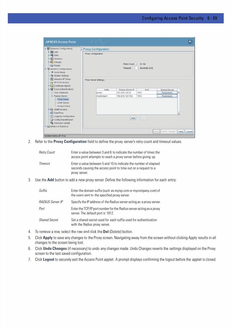
7/18/2019 Motorola AP 5131 Manual
http://slidepdf.com/reader/full/motorola-ap-5131-manual 235/613
Configuring Access Point Security 6 - 59
2. Refer to the Proxy Configuration field to define the proxy server’s retry count and timeout values.
3. Use the Add button to add a new proxy server. Define the following information for each entry:
4. To remove a row, select the row and click the Del (Delete) button.
5. Click Apply to save any changes to the Proxy screen. Navigating away from the screen without clicking Apply results in allchanges to the screen being lost.
6. Click Undo Changes (if necessary) to undo any changes made. Undo Changes reverts the settings displayed on the Proxyscreen to the last saved configuration.
7. Click Logout to securely exit the Access Point applet. A prompt displays confirming the logout before the applet is closed.
Retry Count Enter a value between 3 and 6 to indicate the number of times the
access point attempts to reach a proxy server before giving up.
Timeout Enter a value between 5 and 10 to indicate the number of elapsed
seconds causing the access point to time out on a request to a
proxy server.
Suffix Enter the domain suffix (such as myisp.com or mycompany.com) of
the users sent to the specified proxy server.
RADIUS Server IP Specify the IP address of the Radius server acting as a proxy server.
Port Enter the TCP/IP port number for the Radius server acting as a proxy
server. The default port is 1812.
Shared Secret Set a shared secret used for each suffix used for authentication
with the Radius proxy server.
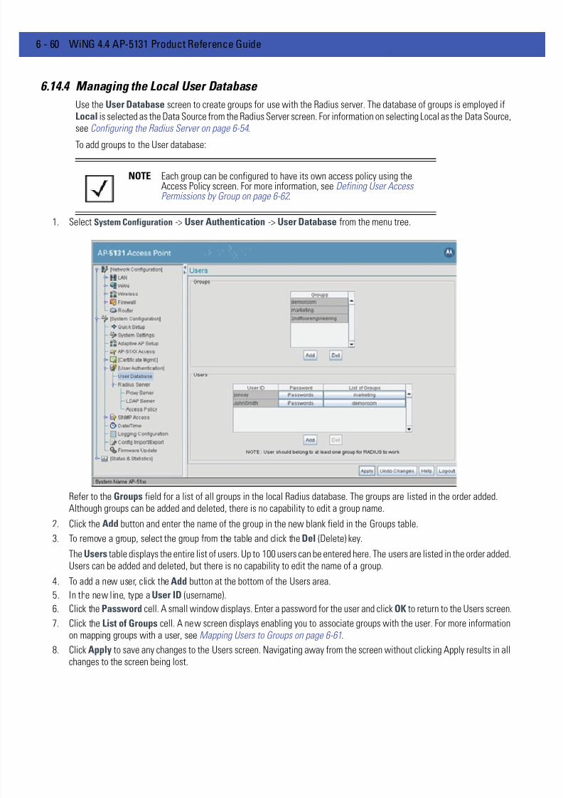
7/18/2019 Motorola AP 5131 Manual
http://slidepdf.com/reader/full/motorola-ap-5131-manual 236/613
6 - 60 WiNG 4.4 AP-5131 Product Reference Guide
6.14.4 Managing the Local User Database
Use the User Database screen to create groups for use with the Radius server. The database of groups is employed ifLocal is selected as the Data Source from the Radius Server screen. For information on selecting Local as the Data Source,see Configuring the Radius Server on page 6-54 .
To add groups to the User database:
1. Select System Configuration -> User Authentication -> User Database from the menu tree.
Refer to the Groups field for a list of all groups in the local Radius database. The groups are listed in the order added.Although groups can be added and deleted, there is no capability to edit a group name.
2. Click the Add button and enter the name of the group in the new blank field in the Groups table.
3. To remove a group, select the group from the table and click the Del (Delete) key.
The Users table displays the entire list of users. Up to 100 users can be entered here. The users are listed in the order added.Users can be added and deleted, but there is no capability to edit the name of a group.
4. To add a new user, click the Add button at the bottom of the Users area.
5. In the new line, type a User ID (username).
6. Click the Password cell. A small window displays. Enter a password for the user and click OK to return to the Users screen.
7. Click the List of Groups cell. A new screen displays enabling you to associate groups with the user. For more informationon mapping groups with a user, see Mapping Users to Groups on page 6-61.
8. Click Apply to save any changes to the Users screen. Navigating away from the screen without clicking Apply results in allchanges to the screen being lost.
NOTE Each group can be configured to have its own access policy using theAccess Policy screen. For more information, see Defining User AccessPermissions by Group on page 6-62 .

7/18/2019 Motorola AP 5131 Manual
http://slidepdf.com/reader/full/motorola-ap-5131-manual 237/613
Configuring Access Point Security 6 - 61
9. Click Undo Changes (if necessary) to undo any changes made. Undo Changes reverts the settings displayed on the Usersscreen to the last saved configuration.
10. Click Logout to securely exit the Access Point applet. A prompt displays confirming the logout before the applet is closed.
6.14.4.1 Mapping Users to Groups
Once users have been created within the Users screen, their access privileges need to be configured for inclusion to one,some or all of the groups also created within the Users screen.
To map users to groups for group authentication privileges:
1. If you are not already in the Users screen, select System Configuration -> User Authentication -> User Database fromthe menu tree.
Existing users and groups display within their respective fields. If user or group requires creation or modification, make yourchanges before you begin to map them.
2. Refer to the Users field and select the List of Groups column for the particular user you wish to map to one or more groups
The Users Group Setting screen displays with the groups available for user inclusion displayed within the Available
column.
3. To add the user to a group, select the group in the Available list (on the right) and click the <-Add button.
Assigned users will display within the Assigned table. Map one or more groups as needed for group authentication accessfor this particular user.
4. To remove the user from a group, select the group in the Assigned list (on the left) and click the Delete-> button.
5. Click the OK button to save your user and group mapping assignments and return to the Users screen.
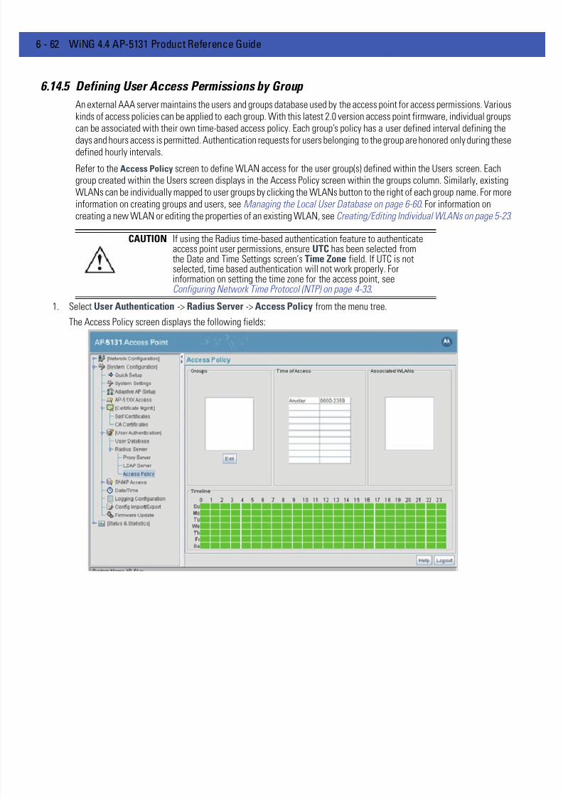
7/18/2019 Motorola AP 5131 Manual
http://slidepdf.com/reader/full/motorola-ap-5131-manual 238/613
6 - 62 WiNG 4.4 AP-5131 Product Reference Guide
6.14.5 Defining User Access Permissions by Group
An external AAA server maintains the users and groups database used by the access point for access permissions. Variouskinds of access policies can be applied to each group. With this latest 2.0 version access point firmware, individual groupscan be associated with their own time-based access policy. Each group’s policy has a user defined interval defining the
days and hours access is permitted. Authentication requests for users belonging to the group are honored only during thesedefined hourly intervals.
Refer to the Access Policy screen to define WLAN access for the user group(s) defined within the Users screen. Eachgroup created within the Users screen displays in the Access Policy screen within the groups column. Similarly, existingWLANs can be individually mapped to user groups by clicking the WLANs button to the right of each group name. For moreinformation on creating groups and users, see Managing the Local User Database on page 6-60 . For information oncreating a new WLAN or editing the properties of an existing WLAN, see Creating/Editing Individual WLANs on page 5-23 .
1. Select User Authentication -> Radius Server -> Access Policy from the menu tree.
The Access Policy screen displays the following fields:
CAUTION If using the Radius time-based authentication feature to authenticateaccess point user permissions, ensure UTC has been selected fromthe Date and Time Settings screen’s Time Zone field. If UTC is notselected, time based authentication will not work properly. For
information on setting the time zone for the access point, seeConfiguring Network Time Protocol (NTP) on page 4-33 .

7/18/2019 Motorola AP 5131 Manual
http://slidepdf.com/reader/full/motorola-ap-5131-manual 239/613
Configuring Access Point Security 6 - 63
2. Review the existing access intervals assigned to each group by selecting the group from amongst those displayed. To modifya group’s permissions, see Editing Group Access Permissions on page 6-63 .
3. Click Logout to securely exit the access point applet. A prompt displays confirming the logout before the applet is closed.
6.14.5.1 Editing Group Access Permissions
The Access Policy screen provides a mechanism for modifying an existing group’s access permissions. A group’spermissions can be set for any day of the week and include any hour of the day. Ten unique access intervals can be defined
for each existing group.To update a group’s access permissions:
1. Select User Authentication -> Radius Server -> Access Policy from the menu tree.
2. Select an existing group from within the groups field.
3. Select the Edit button.
The Edit Access Policy screen displays.
Groups The Groups field displays the names of those existing groups that
can have access intervals applied to them. Click the Edit button to
display a screen designed to create access intervals for specific
days and hours. A mechanism also exists for mapping specific
WLANs to these intervals. For more information, see Editing GroupAccess Permissions on page 6-63 . For information on creating a
new group, see Managing the Local User Database on page 6-60 .
Time of Access The Time of Access field displays the days of the week and the
hours defined for group access to access point resources. This data
is defined for the group by selecting the Edit button from within the
groups field.
Associated WLANs The Associated WLANs field displays the WLANs assigned the
user group access permissions listed within the filters and grid
fields. Add additional WLANs to a group by selecting the Edit
button within the groups field.
Timeline Displays a bar graph of the selected group’s access privileges.Access times are displayed in a grid format with the the days of the
week and hours users access is available displayed in green.
Revise the selected group’s privileges as needed.

7/18/2019 Motorola AP 5131 Manual
http://slidepdf.com/reader/full/motorola-ap-5131-manual 240/613
6 - 64 WiNG 4.4 AP-5131 Product Reference Guide
4. Define up to 10 access policies for the selected group within the Time Based Access Policy field.
Use the drop-down menus on the left-hand side of the screen to define the day of the week for which each policy applies.If continual access is required, select the All Days option. If continual access is required during Monday through Friday, butnot Saturday or Sunday, select the Weekdays option.
Use the Start Time and End Time values to define the access interval (in HHMM format) for each access policy. Each policyfor a given group should have unique intervals. Policies can be created for different intervals on the same day of the week.
5. Refer to the WLANs field to select existing WLANs to apply to the selected group’s set of access permissions.
The group’s existing WLANs are already selected within the Edit screen. Select those additional WLANs requiring the accesspermissions specified in options 1-10 within the Time Based Access Policy field.
6. Click Apply to save any changes to the Edit Access Policy screen. Navigating away from the screen without clicking Applyresults in all changes to the screen being lost.
7. Click Cancel if necessary) to undo any changes made. Undo Changes reverts the settings displayed on the Edit Access Policyscreen to the last saved configuration.
NOTE Groups have a strict start and end time (as defined using the Edit AccessPolicy screen). Only during this period of time can authentication requestsfrom users be honored (with no overlaps). Any authentication requestoutside of this defined interval is denied regardless of whether a user’scredentials match or not.
7/18/2019 Motorola AP 5131 Manual
http://slidepdf.com/reader/full/motorola-ap-5131-manual 241/613
CHAPTER 7 MONITORING STATISTICS
The AP-51x1 has functionality to display robust transmit and receive statistics for its WAN and LAN port. Wireless LocalArea Network (WLAN) stats can also be displayed collectively for each enabled WLAN as well as individually for up to 16specific WLANs.
Transmit and receive statistics can also be displayed for the AP-51x1’s 802.11a and 802.11b/g radios. An advanced radiostatistics page is also available to display retry histograms for specific data packet retry information.
Associated MU stats can be displayed collectively for associated MUs and individually for specific MUs. An echo (ping)test is also available to ping specific MUs to assess the strength of the AP association.
Finally, the AP-51x1 can detect and display the properties of other APs detected within the AP-51x1 radio coverage area.The type of AP detected can be displayed as well as the properties of individual APs.

7/18/2019 Motorola AP 5131 Manual
http://slidepdf.com/reader/full/motorola-ap-5131-manual 242/613
7 - 2 WiNG 4.4 AP-5131 Product Reference Guide
See the following sections for more details on viewing statistics for the AP-51x1:
• Viewing WAN Statistics
• Viewing LAN Statistics
• Viewing Wireless Statistics • Viewing Radio Statistics Summary
• Viewing MU Statistics Summary
• Viewing the Mesh Statistics Summary
• Viewing Known Access Point Statistics

7/18/2019 Motorola AP 5131 Manual
http://slidepdf.com/reader/full/motorola-ap-5131-manual 243/613
Monitoring Statistics 7 - 3
7.1 Viewing WAN Statistics
Use the AP-51x1 WAN Stats screen to view real-time statistics for monitoring the AP-51x1 activity through its Wide AreaNetwork (WAN) port.
The Information field of the WAN Stats screen displays basic WAN information, generated from settings on the WANscreen. The Received and Transmitted fields display statistics for the cumulative packets, bytes, and errors received andtransmitted through the WAN interface since it was last enabled or the AP was last rebooted. The AP-51x1 WAN Statsscreen is view-only with no configurable data fields.
To view AP-51x1 WAN Statistics:
1. Select Status and Statistics -> WAN Stats from the AP-51x1 menu tree.
2. Refer to the Information field to reference the following AP-51x1 WAN data:
Status The Status field displays Enabled if the WAN interface is enabled
on the WAN screen. If the WAN interface is disabled on the WAN
screen, the WAN Stats screen displays no connection information
and statistics. To enable the WAN connection, see Configuring
WAN Settings on page 5-13
HW Address The Media Access Control (MAC) address of the AP-51x1 WAN
port. The WAN port MAC address is hard coded at the factory and
cannot be changed. For more information on how access point
MAC addresses are assigned, see AP-51xx MAC Address
Assignment on page 1-19 .
IP Addresses The displayed Internet Protocol (IP) addresses for the AP-51x1
WAN port.

7/18/2019 Motorola AP 5131 Manual
http://slidepdf.com/reader/full/motorola-ap-5131-manual 244/613
7 - 4 WiNG 4.4 AP-5131 Product Reference Guide
3. Refer to the Received field to reference data received over the AP-51x1 WAN port.
4. Refer to the Transmitted field to reference data received over the AP-51x1 WAN port.
Mask The Mask field displays the subnet mask number for the AP-51x1’s
WAN connection. This value is set on the WAN screen. Refer to
Configuring WAN Settings on page 5-13 to change the subnet
mask.
Link The Link parameter displays Up if the WAN connection is activebetween the AP-51x1 and network, and Down if the WAN
connection is interrupted or lost. Use this information to assess the
current connection status of the WAN port.
Speed The WAN connection speed is displayed in Megabits per second
(Mbps), for example, 54Mbps. If the throughput speed is not
achieved, examine the number of transmit and receive errors, or
consider increasing the supported data rate. To change the data
rate of the 802.11a or 802.11b/g radio, see Configuring the 802.11a
or 802.11b/g Radio on page 5-42 .
RX Packets RX packets are data packets received over the WAN port. The
displayed number is a cumulative total since the WAN interface
was last enabled or the AP-51x1 was last restarted.
RX Bytes RX bytes are bytes of information received over the WAN port. The
displayed number is a cumulative total since the WAN interface
was last enabled or the access point was last restarted. To restart
the AP-51x1 to begin a new data collection, see Configuring
System Settings on page 4-3 .
RX Errors RX errors include dropped data packets, buffer overruns, and frame
errors on inbound traffic. The number of RX errors is a total of RX
Dropped , RX Overruns and RX Carrier errors. Use this information
to determine performance quality of the current WAN connection.
RX Dropped The RX Dropped field displays the number of data packets that fail
to reach the WAN interface. If this number appears excessive,
consider a new connection to the device.
RX Overruns RX overruns are buffer overruns on the WAN connection. RX
overruns occur when packets are received faster than the WAN
port can handle them. If RX overruns are excessive, consider
reducing the data rate, for more information, see Configuring the
802.11a or 802.11b/g Radio on page 5-42 .
RX Frame The RX Frame field displays the number of TCP/IP data frame
errors received.
7/18/2019 Motorola AP 5131 Manual
http://slidepdf.com/reader/full/motorola-ap-5131-manual 245/613
Monitoring Statistics 7 - 5
5. Click the Clear WAN Stats button to reset each of the data collection counters to zero in order to begin new datacollections. The RX/TX Packets and RX/TX Bytes totals remain at their present values and are not cleared.
Do not clear the WAN stats if currently in an important data gathering activity or risk losing all data calculations to that point
6. Click Logout to securely exit the access point applet. A prompt displays confirming the logout before the applet is closed.
TX Packets TX packets are data packets sent over the WAN connection. The
displayed number is a cumulative total since the WAN was last
enabled or the AP-51x1 was last restarted. To begin a new data
collection, see Configuring System Settings on page 4-3 .
TX Bytes TX bytes are bytes of information sent over the WAN connection.
The displayed number is a cumulative total since the WAN
interface was last enabled or the AP-51x1 was last restarted. To
begin a new data collection, see Configuring System Settings on
page 4-3 .
TX Errors TX errors include dropped data packets, buffer overruns, and carrier
errors on outbound traffic. The displayed number of TX errors is the
total of TX Dropped , TX Overruns and TX Carrier errors. Use this
information to assess access point location and transmit speed.
TX Dropped The TX Dropped field displays the number of data packets that fail
to get sent from the WAN interface.
TX Overruns TX overruns are buffer overruns on the WAN connection. TX
overruns occur when packets are sent faster than the WAN
interface can handle. If TX overruns are excessive, consider
reducing the data rate, for more information, see Configuring the
802.11a or 802.11b/g Radio on page 5-42 .
TX Carrier The TX Carrier field displays the number of TCP/IP data carrier
errors.

7/18/2019 Motorola AP 5131 Manual
http://slidepdf.com/reader/full/motorola-ap-5131-manual 246/613
7 - 6 WiNG 4.4 AP-5131 Product Reference Guide
7.2 Viewing LAN Statistics
Use the LAN Stats screen to monitor the activity of the AP-51x1’s LAN1 or LAN2 connection. The Information field of theLAN Stats screen displays network traffic information as monitored over the AP-51x1 LAN1 or LAN2 port. The Receivedand Transmitted fields of the screen display statistics for the cumulative packets, bytes, and errors received andtransmitted over the LAN1 or LAN2 port since it was last enabled or the AP-51x1 was last restarted. The LAN Stats screenis view-only with no user configurable data fields.
To view AP-51x1 LAN connection stats:
1. Select Status and Statistics -> LAN Stats -> LAN1 Stats (or LAN2 Stats) from the AP-51x1 menu tree.
2. Refer to the Information field to view the following AP-51x1 device address information:
Status Displays whether this particular LAN has been enabled as viable
subnet from within the LAN Configuration screen.
IP Address The Internet Protocol (IP) addresses for the AP-51x1 LAN port.
Network Mask The first two sets of numbers specify the network domain, the next
set specifies the subset of hosts within a larger network. These
values help divide a network into subnetworks and simplify routingand data transmission.
Ethernet Address The Media Access Control (MAC) address of the AP-51x1. The MAC
address is hard coded at the factory and cannot be changed. For
more information on how access point MAC addresses are
assigned, see AP-51xx MAC Address Assignment on page 1-19 .
Link The Link parameter displays Up if the LAN connection is active
between the AP-51x1 and network, and Down if the LAN
connection is interrupted or lost. Use this information to assess the
current connection status of LAN 1 or LAN2.

7/18/2019 Motorola AP 5131 Manual
http://slidepdf.com/reader/full/motorola-ap-5131-manual 247/613
Monitoring Statistics 7 - 7
3. Refer to the Received field to view data received over the AP-51x1 LAN port.
4. Refer to the Transmitted field to view statistics transmitted over the AP-51x1 LAN port.
Speed The LAN 1 or LAN 2 connection speed is displayed in Megabits per
second (Mbps), for example, 54Mbps. If the throughput speed is
not achieved, examine the number of transmit and receive errors,
or consider increasing the supported data rate. To change the data
rate of the 802.11a or 802.11b/g radio, see Configuring the 802.11a
or 802.11b/g Radio on page 5-42 .
Duplex Displays whether the current LAN connection is full or half duplex.
WLANs Mapped The WLANs Mapped table lists the WLANs mapped to this LAN
(either LAN1 or LAN2) as their LAN interface.
RX Packets RX packets are data packets received over the AP-51x1 LAN port.
The number is a cumulative total since the LAN connection was
last enabled or the AP-51x1 was last restarted. To begin a new data
collection, see Configuring System Settings on page 4-3 .
RX Bytes RX bytes are bytes of information received over the LAN port. Thevalue is a cumulative total since the LAN connection was last
enabled or the AP-51x1 was last restarted. To begin a new data
collection, see Configuring System Settings on page 4-3 .
RX Errors RX errors include dropped data packets, buffer overruns, and frame
errors on inbound traffic. The number of RX errors is a total of RX
Dropped , RX Overruns and RX Carrier errors. Use this information
to determine performance quality of the current LAN connection.
RX Dropped The RX Dropped field displays the number of data packets failing
to reach the LAN port. If this number appears excessive, consider a
new connection to the device.
RX Overruns RX overruns are buffer overruns on the AP-51x1 LAN port. RXoverruns occur when packets are received faster than the LAN
connection can handle them. If RX overruns are excessive, consider
reducing the data rate, for more information, see Configuring the
802.11a or 802.11b/g Radio on page 5-42 .
RX Frame The RX Frame field displays the number of TCP/IP data frame
errors received.
TX Packets TX packets are data packets sent over the AP-51x1 LAN port. The
displayed number is a cumulative total since the LAN connection
was last enabled or the AP-51x1 was last restarted. To begin a newdata collection, see Configuring System Settings on page 4-3 .
TX Bytes TX bytes are bytes of information sent over the LAN port. The
displayed number is a cumulative total since the LAN Connection
was last enabled or the AP-51x1 was last restarted. To begin a new
data collection, see Configuring System Settings on page 4-3 .
TX Errors TX errors include dropped data packets, buffer overruns, and carrier
errors on outbound traffic. The displayed number of TX errors is a
total of TX Dropped, TX Overruns and TX Carrier errors. Use this
information to re-assess AP location and transmit speed.

7/18/2019 Motorola AP 5131 Manual
http://slidepdf.com/reader/full/motorola-ap-5131-manual 248/613
7 - 8 WiNG 4.4 AP-5131 Product Reference Guide
5. Click the Clear LAN Stats button to reset each of the data collection counters to zero in order to begin new data collections.The RX/TX Packets and RX/TX Bytes totals remain at their present values and are not cleared.
6. Click the Logout button to securely exit the Access Point applet. There will be a prompt confirming logout before the appletis closed.
7.2.1 Viewing STP Statistics for a LAN
Each access point LAN has the ability to track its own unique STP statistics. Refer to the LAN STP Stats page whenassessing mesh networking functionality for each of the two access point LANs. Access points in bridge mode exchangeconfiguration messages at regular intervals (typically 1 to 4 seconds). If a bridge fails, neighboring bridges detect a lack ofconfiguration messaging and initiate a spanning-tree recalculation (when spanning tree is enabled).
To view AP-51x1 LAN’s STP statistics:
1. Select Status and Statistics -> LAN Stats -> LAN1 Stats (or LAN2 Stats) > STP Stats from the AP-51x1 menu tree.
2. Refer to the Spanning Tree Info field to for details on spanning tree state, and root access point designation.
TX Dropped The TX Dropped field displays the number of data packets that fail
to get sent from the AP-51x1 LAN port.
TX Overruns TX overruns are buffer overruns on the LAN port. TX overruns occur
when packets are sent faster than the LAN connection can handle.
If TX overruns are excessive, consider reducing the data rate, formore information, see Configuring the 802.11a or 802.11b/g Radio
on page 5-42 .
TX Carrier The TX Carrier field displays the number of TCP/IP data carrier
errors.

7/18/2019 Motorola AP 5131 Manual
http://slidepdf.com/reader/full/motorola-ap-5131-manual 249/613
Monitoring Statistics 7 - 9
3. Refer to the Port Interface Table to assess the state of the traffic over the ports listed within the table for the root andbridge and designated bridges.
Spanning Tree State Displays whether the spanning tree state is currently enabled or
disabled. The spanning tree state must be enabled for a unique
spanning-tree calculation to occur when the bridge is powered up
or when a topology change is detected.
Designated Root Displays the access point MAC address of the bridge defined as the
root bridge in the Bridge STP Configuration screen. For information
on defining an access point as a root bridge, see Setting the LAN
Configuration for Mesh Networking Support on page 9-5 .
Bridge ID The Bridge ID identifies the priority and ID of the bridge sending the
message
Root Port Number Identifies the root bridge by listing its 2-byte priority followed by its
6-byte ID.
Root Path Cost Bridge message traffic contains information identifying the root
bridge and the sending bridge. The root path cost represents the
distance (cost) from the sending bridge to the root bridge.
Bridge Max Msg. Age The Max Msg Age measures the age of received protocol
information recorded for a port, and to ensure the information is
discarded when it exceeds the value set for the Maximum
Message age timer. For information on setting the Maximum
Message Age. For information on setting the Bridge Max Msg.
Age, see Setting the LAN Configuration for Mesh Networking
Support on page 9-5 .
Bridge Hello Time The Bridge Hello Time is the time between each bridge protocol
data unit sent. This time is equal to 2 seconds (sec) by default, but
can tuned between 1 and 10 sec. For information on setting the
Bridge Hello Time, see Setting the LAN Configuration for Mesh
Networking Support on page 9-5 . The 802.1d specificationrecommends the Hello Time be set to a value less than half of the
Max Message age value.
Bridge Forward Delay The Bridge Forward Delay value is the time spent in a listening and
learning state. This time is equal to 15 sec by default, but you can
tune the time to be between 4 and 30 sec. For information on
setting the Bridge Forward Delay, see Setting the LAN
Configuration for Mesh Networking Support on page 9-5 .
Port ID Identifies the port from which the configuration message was sent.
State Displays whether a bridge is forwarding traffic to other members
of the mesh network (over this port) or blocking traffic. Each viable
member of the mesh network must forward traffic to extent the
coverage area of the mesh network.
Path Cost The root path cost is the distance (cost) from the sending bridge to
the root bridge.
Designated Root Displays the MAC address of the access point defined with the
lowest priority within the Mesh STP Configuration screen.
7/18/2019 Motorola AP 5131 Manual
http://slidepdf.com/reader/full/motorola-ap-5131-manual 250/613
7 - 10 WiNG 4.4 AP-5131 Product Reference Guide
4. Click the Logout button to securely exit the Access Point applet. There will be a prompt confirming logout before the appletis closed.
Designated Bridge There is only one root bridge within each mesh network. All other
bridges are designated bridges that look to the root bridge for
several mesh network timeout values. For information on root and
bridge designations, see Setting the LAN Configuration for Mesh
Networking Support on page 9-5 .
Designated Port Each designated bridge must use a unique port. The value listed
represents the port used by each bridge l isted within the table to
route traffic to other members of the mesh network.
Designated Cost Displays the unique distance between each access point MAC
address listed in the Designated Bridge column and the access
point MAC address listed in the Designated Root column.

7/18/2019 Motorola AP 5131 Manual
http://slidepdf.com/reader/full/motorola-ap-5131-manual 251/613
Monitoring Statistics 7 - 11
7.3 Viewing Wireless Statistics
Use the WLAN Statistics Summary screen to view overview statistics for active (enabled) WLANs on the AP-51x1. The WLAN Summary field displays basic information such as number of Mobile Units (MUs) and total throughput for each ofthe active WLANs. The Total RF Traffic section displays basic throughput information for all RF activity on the AP-51x1.The WLAN Statistics Summary screen is view-only with no user configurable data fields.
If a WLAN is not displayed within the Wireless Statistics Summary screen, see Enabling Wireless LANs (WLANs) on page
5-21 to enable the WLAN. For information on configuring the properties of individual WLANs, see Creating/Editing IndividualWLANs on page 5-23 .
To view AP-51x1 WLAN Statistics:
1. Select Status and Statistics -> Wireless Stats from the AP-51x1 menu tree.
2. Refer to the WLAN Summary field to reference high-level data for each enabled WLAN.
Name Displays the names of all the enabled WLANs on the AP-51x1. For
information on enabling a WLAN, see Enabling Wireless LANs
(WLANs) on page 5-21.
MUs Displays the total number of MUs currently associated with eachenabled WLAN. Use this information to assess if the MUs are
properly grouped by function within each enabled WLAN. To adjust
the maximum number of MUs permissible per WLAN, see
Creating/Editing Individual WLANs on page 5-23 .
T-put Displays the total throughput in Megabits per second (Mbps) for
each active WLAN.
ABS Displays the Average Bit Speed (ABS) in Megabits per second
(Mbps) for each active WLAN displayed.

7/18/2019 Motorola AP 5131 Manual
http://slidepdf.com/reader/full/motorola-ap-5131-manual 252/613
7 - 12 WiNG 4.4 AP-5131 Product Reference Guide
3. Refer to the Total AP RF Traffic field to view throughput information for the AP-51x1 and WLAN.
4. Click the Clear RF Stats button to reset each of the data collection counters to zero in order to begin new data collections.
5. Click the Logout button to securely exit the access point applet. A prompt displays confirming the logout before the appletis closed.
7.3.1 Viewing WLAN Statistics
Use the WLAN Stats screen to view detailed statistics for individual WLANs.The WLAN Stats screen is separated intofour fields; Information, Traffic , RF Status , and Errors . The Information field displays basic information such as number ofassociated Mobile Units, ESSID and security information. The Traffic field displays statistics on RF traffic and throughput.The RF Status field displays information on RF signal averages from the associated MUs. The Error field displays RFtraffic errors based on retries, dropped packets, and undecryptable packets. The WLAN Stats screen is view-only with nouser configurable data fields.
To view statistics for an individual WLAN:
1. Select Status and Statistics -> Wireless Stats -> WLANx Stats (x = target WLAN) from the AP-51x1 menu tree.
% NU Displays a percentage of the total packets for each active WLAN
that are non-unicast. Non-unicast packets include broadcast and
multicast packets.
Retries Displays the average number of retries per packet. An excessive
number could indicate possible network or hardware problems.Clear All WLAN Stats Click this button to reset each of the data collection counters to
zero in order to begin new data collections.
Do not clear the WLAN stats if currently in an important data
gathering activity or risk losing all data calculations to that point.
Total pkts per second Displays the average number of RF packets sent per second across
all active WLANs on the AP-51x1. The number in black represents
packets for the last 30 seconds and the number in blue represents
total pkts per second for the last hour.
Total bits per second Displays the average bits sent per second across all active WLANs
on the access point. The number in black displays this statistic for
the last 30 seconds and the number in blue displays this statistic
for the last hour.
Total associated MUs Displays the current number of MUs associated with the active
WLANs on the AP-51x1. If the number is excessive, reduce the
maximum number of MUs that can associate with the AP-51x1, for
more information, see Creating/Editing Individual WLANs on page
5-23 .
Clear all RF Stats Click the Clear all RF Stats button to reset statistic counters for
each WLAN, and the Total AP RF totals to 0. Do not clear RF stats
if currently in an important data gathering activity or risk losing alldata calculations to that point.

7/18/2019 Motorola AP 5131 Manual
http://slidepdf.com/reader/full/motorola-ap-5131-manual 253/613
Monitoring Statistics 7 - 13
2. Refer to the Information field to view specific WLAN address, MU and security scheme information for the WLAN selectedfrom the AP-51x1 menu tree.
3. Refer to the Traffic field to view performance and throughput information for the WLAN selected from the AP-51x1 menutree.
ESSID Displays the Extended Service Set ID (ESSID) for the target WLAN.
Radio/s Displays the name of the 802.11a or 802.11b/g radio the target
WLAN is using for AP-51x1 transmissions.
Authentication Type Displays the authentication type (802.1x EAP or Kerberos) defined
for the WLAN. If the authentication type does not match the
desired scheme for the WLAN or needs to be enabled, see Enabling
Authentication and Encryption Schemes on page 6-5 .
Encryption Type Displays the encryption method defined for the WLAN. If the
encryption type does not match the desired scheme for the WLAN
or needs to be enabled, see Enabling Authentication and
Encryption Schemes on page 6-5 .
Num. Associated MUs Displays the total number of MUs currently associated with the
WLAN. If this number seems excessive, consider segregating MU’s
to other WLANs if appropriate.

7/18/2019 Motorola AP 5131 Manual
http://slidepdf.com/reader/full/motorola-ap-5131-manual 254/613
7 - 14 WiNG 4.4 AP-5131 Product Reference Guide
4. Refer to the RF Status field to view the following MU signal, noise and performance information for the WLAN selectedfrom the AP-51x1 menu tree.
5. Refer to the Errors field to view MU association error statistics for the WLAN selected from the AP-51x1 menu tree.
Pkts per second The Total column displays the average total packets per second
crossing the selected WLAN. The Rx column displays the average
total packets per second received on the selected WLAN. The Tx
column displays the average total packets per second sent on the
selected WLAN. The number in black represents this statistic forthe last 30 seconds and the number in blue represents this statistic
for the last hour.
Throughput The Total column displays average throughput in Mbps for a given
time period on the selected WLAN. The Rx column displays
average throughput in Mbps for packets received on the selected
WLAN. The Tx column displays average throughput for packets
sent on the selected WLAN. The number in black represents
statistics for the last 30 seconds and the number in blue represents
statistics for the last hour. Use this information to assess whether
the current AP-51x1 data rate is sufficient to support required
network traffic.
Avg. Bit Speed The Total column displays the average bit speed in Mbps for a
given time period on the selected WLAN.This includes all packets
that are sent and received. The number in black represents
statistics for the last 30 seconds and the number in blue represents
statistics for the last hour. If the bit speed is significantly slower
than the selected data rate, refer to the RF Statistics and Errorsfields to troubleshoot.
% Non-unicast pkts Displays the percentage of the total packets that are non-unicast.
Non-unicast packets include broadcast and multicast packets.The
number in black represents packets for the last 30 seconds and the
number in blue represents packets for the last hour.
Avg MU Signal Displays the average RF signal strength in dBm for all MUs
associated with the selected WLAN. The number in black
represents this statistic for the last 30 seconds and the number in
blue represents this statistic for the last hour. If the signal is low,
consider mapping the MU to a different WLAN if a better functional
grouping of MUs can be determined.
Avg MU Noise Displays the average RF noise for all MUs associated with the
selected WLAN. The number in black represents MU noise for the
last 30 seconds and the number in blue represents MU noise for the
last hour. If MU noise is excessive, consider moving the MU closerto the AP-51x1, or in area with less conflicting network traffic.
Avg MU SNR Displays the average Signal to Noise Ratio (SNR) for all MUs
associated with the selected WLAN. The Signal to Noise Ratio is
an indication of overall RF performance on your wireless networks.

7/18/2019 Motorola AP 5131 Manual
http://slidepdf.com/reader/full/motorola-ap-5131-manual 255/613
Monitoring Statistics 7 - 15
6. Click the Clear WLAN Stats button to reset each of the data collection counters to zero in order to begin new datacollections.
Do not clear the WLAN stats if currently in an important data gathering activity or risk losing all data calculations to thatpoint.
7. Click the Logout button to securely exit the access point applet. A prompt displays confirming the logout before the appletis closed.
Avg Num of Retries Displays the average number of retries for all MUs associated with
the selected WLAN. The number in black represents average
retries for the last 30 seconds and the number in blue represents
average retries for the last hour.
Dropped Packets Displays the percentage of packets which the AP gave up on for all
MUs associated with the selected WLAN. The number in black
represents this statistic for the last 30 seconds and the number in
blue represents this statistic for the last hour.
% of Undecryptable
Pkts
Displays the percentage of undecryptable packets for all MUs
associated with the selected WLAN. The number in black
represents undecryptable pkts for the last 30 seconds and the
number in blue represents undecryptable pkts for the last hour.
NOTE The Apply and Undo Changes buttons are not available on the WLANStatistics screen as this screen is view only with no configurable data
fields.

7/18/2019 Motorola AP 5131 Manual
http://slidepdf.com/reader/full/motorola-ap-5131-manual 256/613
7 - 16 WiNG 4.4 AP-5131 Product Reference Guide
7.4 Viewing Radio Statistics Summary
Select the Radio Stats Summary screen to view high-level information (radio name, type, number of associated MUs,etc.) for the radio(s) enabled on an AP-51x1. Individual radio statistics can be displayed as well by selecting a specific radiofrom within the AP-51x1 menu tree.
To view high-level AP-51x1 radio statistics:
1. Select Status and Statistics -> Radio Stats from the AP-51x1 menu tree.
2. Refer to the Radio Summary field to reference AP-51x1 radio information.
Type Displays the type of radio (either 802.11a or 802.11b/g) currently
deployed by the AP-51x1. To configure the radio type, see Setting
Radio Configuration for a WLAN on page 5-38 .
MUs Displays the total number of MUs currently associated with each
AP-51x1 radio.
T-put Displays the total throughput in Megabits per second (Mbps) for
each AP-51x1 radio listed. To adjust the data rate for a specific
radio, see Configuring the 802.11a or 802.11b/g Radio on page 5- 42 .
ABS Displays the Average Bit Speed (ABS) in Megabits per second
(Mbps) for each AP-51x1 radio.
RF Util Displays the approximate RF Utilization for each AP-51x1 radio
% NU Displays the percentage of the total packets that are non-unicast.
Non-unicast packets include broadcast and multicast packets.
Retries Displays the average number of retries per packet on each radio. A
high number could indicate network or hardware problems.

7/18/2019 Motorola AP 5131 Manual
http://slidepdf.com/reader/full/motorola-ap-5131-manual 257/613
Monitoring Statistics 7 - 17
3. Click the Clear All Radio Stats button to reset each of the data collection counters to zero in order to begin new datacollections.
Do not clear the radio stats if currently in an important data gathering activity or risk losing all data calculations to that point
For information on viewing radio statistics particular to the AP-51x1 radio type displayed within the AP Stats Summary
screen, see Viewing Radio Statistics on page 7-17 .
4. Click the Logout button to securely exit the Access Point applet.
7.4.1 Viewing Radio Statistics
Refer to the Radio Stats screen to view detailed information for the AP-51x1 radio (either 802.11a or 802.11b/g) displayedwithin the Radio Summary screen. There are four fields within the screen. The Information field displays device addressand location information, as well as channel and power information. The Traffic field displays statistics for cumulativepackets, bytes, and errors received and transmitted. The Traffic field does not add retry information to the stats displayed.Refer to the RF Status field for an average MU signal, noise and signal to noise ratio information. Finally, the Errors fielddisplays retry information as well as data transmissions the AP-51x1 radio either dropped or could not decrypt. Theinformation within the 802.11a Radio Statistics screen is view-only with no configurable data fields.
To view detailed radio statistics:
1. Select Status and Statistics -> Radio Stats -> Radio1(802.11b/g) Stats from the AP-51x1 menu tree.
2. Refer to the Information field to view the AP-51x1 802.11a or 802.11b/g radio’s MAC address, placement and transmissioninformation.
HW Address The Media Access Control (MAC) address of the AP-51x1 housing
the 802.11a radio. The MAC address is set at the factory and can
be found on the bottom of the access point. For more information
on how access point MAC addresses are assigned, see AP-51xx
MAC Address Assignment on page 1-19 .
Radio Type Displays the radio type (either 802.11a or 802.11b/g).

7/18/2019 Motorola AP 5131 Manual
http://slidepdf.com/reader/full/motorola-ap-5131-manual 258/613
7 - 18 WiNG 4.4 AP-5131 Product Reference Guide
3. Refer to the Traffic field to view performance and throughput information for the target AP-51x1 802.11a or 802.11b/g radio.
4. Refer to the RF Status field to view the following MU signal, noise and performance information for the target AP-51x1802.11a or 802.11b/g radio.
Power The power level in milliwatts (mW) for RF signal strength. To
change the power setting for the radio, see Configuring the
802.11a or 802.11b/g Radio on page 5-42 .
Active WLANs Lists the AP-51x1 WLANs adopted by the 802.11a or
802.11b/g radio.Placement Lists whether the AP-51x1 radio is indoors or outdoors. To change
the placement setting, see Configuring the 802.11a or 802.11b/g
Radio on page 5-42 .
Current Channel Indicates the channel for communications between the AP-51x1
radio and its associated MUs. To change the channel setting, see
Configuring the 802.11a or 802.11b/g Radio on page 5-42 .
Num Associated MUs Lists the number of mobile units (MUs) currently associated with
the AP-51x1 802.11a or 802.11b/g radio.
Pkts per second The Total column displays the average total packets per second
crossing the radio. The Rx column displays the average total
packets per second received. The Tx column displays the average
total packets per second transmitted. The number in black
represents this statistic for the last 30 seconds and the number in
blue represents this statistic for the last hour.
Throughput The Total column displays average throughput on the radio. The Rx
column displays average throughput in Mbps for packets received.
The Tx column displays average throughput for packets
transmitted. The number in black represents statistics for the last
30 seconds and the number in blue represents statistics for the last
hour. Use this information to assess whether the currentthroughput is sufficient to support required network traffic.
Avg. Bit Speed The Total column displays the average bit speed in Mbps for the
radio This includes all packets transmitted and received. The
number in black represents statistics for the last 30 seconds and
the number in blue represents statistics for the last hour.
Approximate RF
Utilization
The approximate RF utilization of the AP-51x1 radio. This value is
calculated as throughput divided by average bit speed. The number
in black represents this statistic for the last 30 seconds and the
number in blue represents this statistic for the last hour.
% Non-unicast pkts Displays the percentage of total radio packets that are non-unicast.
Non-unicast packets include broadcast and multicast packets.The
number in black represents packets for the last 30 seconds and the
number in blue represents packets for the last hour.
7/18/2019 Motorola AP 5131 Manual
http://slidepdf.com/reader/full/motorola-ap-5131-manual 259/613
Monitoring Statistics 7 - 19
5. Refer to the Errors field to reference retry information as well as data transmissions the target AP-51x1 802.11a or 802.11
b/g radio either gave up on could not decrypt.
6. Click the Clear Radio Stats button to reset each of the data collection counters to zero in order to begin new datacollections.
7. Click the Logout button to securely exit the Access Point applet.
7.4.1.1 Retry Histogram
Refer to the Retry Histrogram screen for an overview of the retries transmitted by an access point radio and whetherthose retries contained any data packets. Use this information in combination with the error fields within a Radio Statsscreen to assess overall radio performance.
To display a Retry Histogram screen for an access point radio:
1. Select Status and Statistics -> Radio Stats -> Radio1(802.11b/g) Stats -> Retry Histogram from the AP-51x1 menutree.
A Radio Histogram screen is available for each access point radio (regardless of single or dual-radio model).
Avg MU Signal Displays the average RF signal strength in dBm for all MUs
associated with the radio. The number in black represents the
average signal for the last 30 seconds and the number in blue
represents the average signal for the last hour. If the signal is low,
consider mapping the MU to a different WLAN, if a betterfunctional grouping of MUs can be determined.
Avg MU Noise Displays the average RF noise for all MUs associated with the AP-
51x1 radio. The number in black represents MU noise for the last
30 seconds and the number in blue represents MU noise for the last
hour. If MU noise is excessive, consider moving the MU closer to
the AP-51x1, or in area with less conflicting network traffic.
Avg MU SNR Displays the average Signal to Noise Ratio (SNR) for all MUs
associated with the AP-51x1 radio. The Signal to Noise Ratio is an
indication of overall RF performance on your wireless network.
Avg Num. of Retries Displays the average number of retries for all MUs associated with
the AP-51x1 802.11a or 802.11b/g radio. The number in black
represents retries for the last 30 seconds and the number in blue
represents retries for the last hour.
Dropped Packets Displays the percentage of packets the AP gave up on for all MUs
associated with the AP-51x1 802.11a or 802.11b/g radio. The
number in black represents this statistic for the last 30 seconds and
the number in blue represents this statistic for the last hour.
% of Undecryptable
Pkts
Displays the percentage of undecryptable packets for all MUs
associated with the 802.11a or 802.11b/g radio. The number inblack represents packets for the last 30 seconds and the number in
blue represents packets for the last hour.
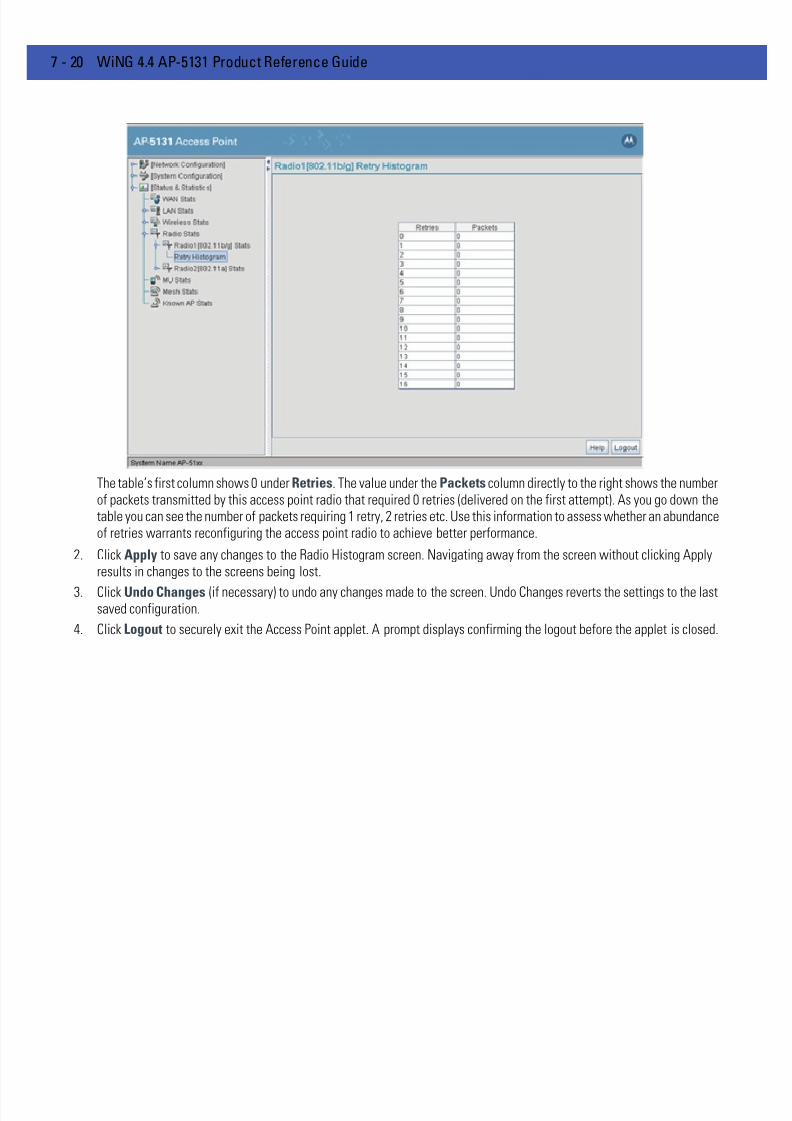
7/18/2019 Motorola AP 5131 Manual
http://slidepdf.com/reader/full/motorola-ap-5131-manual 260/613
7 - 20 WiNG 4.4 AP-5131 Product Reference Guide
The table’s first column shows 0 under Retries. The value under the Packets column directly to the right shows the numberof packets transmitted by this access point radio that required 0 retries (delivered on the first attempt). As you go down thetable you can see the number of packets requiring 1 retry, 2 retries etc. Use this information to assess whether an abundanceof retries warrants reconfiguring the access point radio to achieve better performance.
2. Click Apply to save any changes to the Radio Histogram screen. Navigating away from the screen without clicking Applyresults in changes to the screens being lost.
3. Click Undo Changes (if necessary) to undo any changes made to the screen. Undo Changes reverts the settings to the lastsaved configuration.
4. Click Logout to securely exit the Access Point applet. A prompt displays confirming the logout before the applet is closed.

7/18/2019 Motorola AP 5131 Manual
http://slidepdf.com/reader/full/motorola-ap-5131-manual 261/613
Monitoring Statistics 7 - 21
7.5 Viewing MU Statistics Summary
Use the MU Stats Summary screen to display overview statistics for mobile units (MUs) associated with the AP-51x1.The MU List field displays basic information such as IP Address and total throughput for each associated MU. The MUStats screen is view-only with no user configurable data fields. However, individual MUs can be selected from within theMU Stats Summary screen to either ping to assess interoperability or display authentication statistics.
To view AP-51x1 overview statistics for all of the MUs associated to the AP-51x1:
1. Select Status and Statistics - > MU Stats from the AP-51x1 menu tree.
2. Refer to the MU List field to reference associated MU address, throughput and retry information.
3. Click the Refresh button to update the data collections displayed without resetting the data collections to zero.
4. Click the Echo Test button to display a screen for verifying the link with an associated MU.
For detailed information on conducting a ping test for an MUs, see Pinging Individual MUs on page 7-24 .
IP Address Displays the IP address of each of the associated MU.
MAC Address Displays the MAC address of each of the associated MU.
WLAN Displays the WLAN name each MU is interoperating with.
Radio Displays the name of the 802.11a or 802.11b/g radio each MU is
associated with.
T-put Displays the total throughput in Megabits per second (Mbps) for
each associated MU.
ABS Displays the Average Bit Speed (ABS) in Megabits per second
(Mbps) for each associated MU.
Retries Displays the average number of retries per packet. A high number
retries could indicate possible network or hardware problems.
Hotspot Displays whether this radio is currently supporting a hotspot.

7/18/2019 Motorola AP 5131 Manual
http://slidepdf.com/reader/full/motorola-ap-5131-manual 262/613
7 - 22 WiNG 4.4 AP-5131 Product Reference Guide
5. Click the MU Authentication Statistics button to display a screen with detailed authentication statistics for the an MU.
For information on individual MU authentication statistics, see MU Authentication Statistics on page 7-24 .
6. Click the MU Details button to display a screen with detailed statistics for a selected MU.
For detailed information on individual MU authentication statistics, see Viewing MU Details on page 7-22 .
7. Click the Clear All MU Stats button to reset each of the data collection counters to zero in order to begin new datacollections.
8. Click the Logout button to securely exit the Access Point applet. A prompt displays confirming the logout before the appletis closed.
7.5.1 Viewing MU Details Use the MU Details screen to display throughput, signal strength and transmit error information for a specific MUassociated with the AP-51x1.
The MU Details screen is separated into four fields; MU Properties , MU Traffic , MU Signal , and MU Errors . The MUProperties field displays basic information such as hardware address, IP address, and associated WLAN and AP.Reference the MU Traffic field for MU RF traffic and throughput data. Use the RF Status field to reference informationon RF signal averages from the target MU. The Error field displays RF traffic errors based on retries, dropped packets andundecryptable packets. The MU Details screen is view-only with no user configurable data fields.
To view details specific to an individual MU:
1. Select Status and Statistics -> MU Stats from the AP-51x1 menu tree.
2. Highlight a specific MU.3. Select the MU Details button.
4. Refer to the MU Properties field to view MU address information.
NOTE An echo test initiated from the AP-51x1 MU Stats Summary screen usesWNMP pings. Therefore, target clients that are not Motorola SolutionsMUs are unable to respond to the echo test.
IP Address Displays the IP address of the MU.
WLAN Association Displays the name of the WLAN the MU is associated with. Use
this information to assess whether the MU is properly grouped
within that specific WLAN.
PSP State Displays the current PSP state of the MU. The PSP Mode field has
two potential settings. PSP indicates the MU is operating in Power
Save Protocol mode. In PSP, the MU runs enough power to check
for beacons and is otherwise inactive. CAM indicates the MU iscontinuously aware of all radio traffic. Motorola Solutions
recommends CAM for those MUs transmitting with the AP
frequently and for periods of time of two hours.
HW Address Displays the Media Access Control (MAC) address for the MU.
Radio Association Displays the name of the AP MU is currently associated with. If the
name of the AP-51x1 requires modification, see Configuring
System Settings on page 4-3 .

7/18/2019 Motorola AP 5131 Manual
http://slidepdf.com/reader/full/motorola-ap-5131-manual 263/613
Monitoring Statistics 7 - 23
5. Refer to the Traffic field to view individual MU RF throughput information.
6. Refer to the RF Status field to view MU signal and signal disturbance information.
7. Refer to the Errors field to view MU retry information and statistics on packets not transmitted.
QoS Client Type Displays the data type transmitted by the mobile unit. Possible
types include Legacy, Voice, WMM Baseline and Power Save.
For more information, see Setting the WLAN Quality of Service
(QoS) Policy on page 5-29 .
Encryption Displays the encryption scheme deployed by the associated MU.
Packets per second The Total column displays average total packets per second
crossing the MU. The Rx column displays the average total packets
per second received on the MU. The Tx column displays the
average total packets per second sent on the MU. The number in
black represents Pkts per second for the last 30 seconds and the
number in blue represents Pkts per second for the last hour.
Throughput The Total column displays the average total packets per second
crossing the selected MU. The Rx column displays the average
total packets per second received on the MU. The Tx columndisplays the average total packets per second sent on the MU. The
number in black represents throughput for the last 30 seconds, the
number in blue represents throughput for the last hour.
Avg. Bit Speed The Total column displays the average bit speed in Mbps for a
given time period on the MU. This includes all packets sent and
received. The number in black represents average bit speed for the
last 30 seconds and the number in blue represents average bit
speed for the last hour. Consider increasing the data rate of the AP
if the current bit speed does not meet network requirements. For
more information, see Configuring the 802.11a or 802.11b/g Radio
on page 5-42 . The associated MU must also be set to the higher
rate to interoperate with the AP-51x1 at that data rate.% of Non-unicast pkts Displays the percentage of the total packets for the selected
mobile unit that are non-unicast. Non-unicast packets include
broadcast and multicast packets. The number in black represents
packets for the last 30 seconds and the number in blue represents
packets for the last hour.
Avg MU Signal Displays RF signal strength in dBm for the target MU. The number
in black represents signal information for the last 30 seconds and
the number in blue represents signal information for the last hour.
Avg MU Noise Displays RF noise for the target MU. The number in blackrepresents noise for the last 30 seconds, the number in blue
represents noise for the last hour.
Avg MU SNR Displays the Signal to Noise Ratio (SNR) for the target MU. The
Signal to Noise Ratio is an indication of overall RF performance on
your wireless network.

7/18/2019 Motorola AP 5131 Manual
http://slidepdf.com/reader/full/motorola-ap-5131-manual 264/613
7 - 24 WiNG 4.4 AP-5131 Product Reference Guide
8. Click OK to exit the screen.
7.5.2 Pinging Individual MUs
The AP-51x1 can verify its link with an MU by sending WNMP ping packets to the associated MU. Use the Echo Test screen to specify a target MU and configure the parameters of the ping test.
To ping a specific MU to assess its connection with an AP-51x1:
1. Select Status and Statistics - > MU Stats from the AP-51x1 menu tree.
2. Select the Echo Test button from within the MU Stats Summary screen
3. Specify the following ping test parameters.
4. Click the Ping button to begin transmitting ping packets to the station address specified.
Refer to the Number of Responses parameter to assess the number of responses from the target MU versus the numberof pings transmitted by the AP-51x1. Use the ratio of packets sent versus packets received to assess the link quality betweenMU and the AP-51x1
Click the Ok button to exit the Echo Test screen and return to the MU Stats Summary screen.
7.5.3 MU Authentication Statistics
The AP-51x1 can access and display authentication statistics for individual MUs.
To view AP-51x1 authentication statistics for a specific MU:
1. Select Status and Statistics - > MU Stats from the AP-51x1 menu tree.
Avg Num of Retries Displays the average number of retries for the MU. The number in
black represents average retries for the last 30 seconds and the
number in blue represents average retries for the last hour.
Dropped Packets Displays the percentage of packets the AP gave up as not receivedon for the selected MU. The number in black represents the
percentage of packets for the last 30 seconds and the number in
blue represents the percentage of packets for the last hour.
% of Undecryptable
Pkts
Displays the percentage of undecryptable packets for the MU. The
number in black represents the percentage of undecryptable
packets for the last 30 seconds and the number in blue represents
the percentage of undecryptable packets for the last hour.
NOTE An echo test initiated from the AP-51x1 MU Stats Summary screen usesWNMP pings. Therefore, target clients that are not Motorola SolutionsMUs are unable to respond to the echo test.
Station Address The IP address of the target MU. Refer to the MU Stats Summaryscreen for associated MU IP address information.
Number of ping Specify the number of ping packets to transmit to the target MU.
The default is 100.
Packet Length Specify the length of each data packet transmitted to the target
MU during the ping test. The default is 100 bytes.
Packet Data Defines the data to be transmitted as part of the test.

7/18/2019 Motorola AP 5131 Manual
http://slidepdf.com/reader/full/motorola-ap-5131-manual 265/613
Monitoring Statistics 7 - 25
2. Highlight a target MU from within the MU List field.
3. Click the MU Authentication Statistics button
Use the displayed statistics to determine if the target MU would be better served with a different AP-51x1 WLAN or AP-51x1 radio.
4. Click Ok to return to the MU Stats Summary screen.

7/18/2019 Motorola AP 5131 Manual
http://slidepdf.com/reader/full/motorola-ap-5131-manual 266/613
7 - 26 WiNG 4.4 AP-5131 Product Reference Guide
7.6 Viewing the Mesh Statistics Summary
The AP-51x1 has the capability of detecting and displaying the properties of other access points in mesh network (eitherbase bridges or client bridges) mode. This information is used to create a list of known wireless bridges.
To view detected mesh network statistics:1. Select Status and Statistics -> Mesh Stats from the AP-51x1 menu tree.
The Mesh Statistics Summary screen displays the following information:
2. Click the Refresh button to update the display of the Mesh Statistics Summary screen to the latest values.
Conn Type Displays whether the bridge has been defined as a base bridge or
a client bridge. For information on defining configuring the access
point as either a base or client bridge, see Configuring Mesh
Networking Support on page 9-5 .
MAC Address The unique 48-bit, hard-coded Media Access Control address,
known as the devices station identifier. This value is hard coded at
the factory by the manufacturer and cannot be changed.
WLAN Displays the WLAN name each wireless bridge is interoperating
with.
Radio Displays the name of the 802.11a or 802.11b/g radio each bridge is
associated with.
T-put Displays the total throughput in Megabits per second (Mbps) for
each associated bridge.
ABS Displays the Average Bit Speed (ABS) in Megabits per second
(Mbps) for each associated bridge.
Retries Displays the average number of retries per packet. A high number
retries could indicate possible network or hardware problems.

7/18/2019 Motorola AP 5131 Manual
http://slidepdf.com/reader/full/motorola-ap-5131-manual 267/613
Monitoring Statistics 7 - 27
3. Click the Details button to display address and radio information for those access points in a client bridge configurationwith this detecting access point.
4. Click the Logout button to securely exit the Access Point applet. A prompt displays confirming the logout before the appletis closed.

7/18/2019 Motorola AP 5131 Manual
http://slidepdf.com/reader/full/motorola-ap-5131-manual 268/613
7 - 28 WiNG 4.4 AP-5131 Product Reference Guide
7.7 Viewing Known Access Point Statistics
The AP-51x1 has the capability of detecting and displaying the properties of other Motorola Solutions access pointslocated within its coverage area. Detected AP-51x1’s transmit a WNMP message indicating their channel, IP address,firmware version, etc. This information is used to create a known AP list. The list has field indicating the properties of theaccess point discovered.
To view detected access point statistics:
1. Select Status and Statistics -> Known AP Stats from the AP-51x1 menu tree.
The Known AP Statistics screen displays the following information:
2. Click the Clear Known AP Stats button to reset each of the data collection counters to zero in order to begin new datacollections.
3. Click the Details button to display access point address and radio information.
NOTE The Known AP Statistics screen only displays statistics for accesspoints located on the same subnet.
IP Address The network-assigned Internet Protocol address of the located AP.
MAC Address The unique 48-bit, hard-coded Media Access Control address,known as the devices station identifier. This value is hard coded at
the factory by the manufacturer and cannot be changed.
MUs The number MUs associated with the located AP-51x1.
Unit Name Displays the name assigned to the AP-51x1 using the System
Settings screen. For information on changing the unit name, see
Configuring System Settings on page 4-3 .
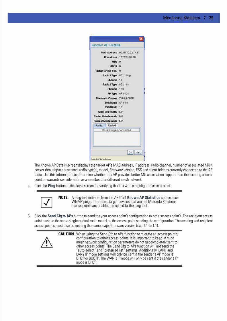
7/18/2019 Motorola AP 5131 Manual
http://slidepdf.com/reader/full/motorola-ap-5131-manual 269/613
Monitoring Statistics 7 - 29
The Known AP Details screen displays the target AP’s MAC address, IP address, radio channel, number of associated MUs,
packet throughput per second, radio type(s), model, firmware version, ESS and client bridges currently connected to the APradio. Use this information to determine whether this AP provides better MU association support than the locating accesspoint or warrants consideration as a member of a different mesh network.
4. Click the Ping button to display a screen for verifying the link with a highlighted access point.
5. Click the Send Cfg to APs button to send the your access point’s configuration to other access point’s. The recipient accesspoint must be the same single or dual-radio model as the access point sending the configuration. The sending and recipient
access point’s must also be running the same major firmware version (i.e., 1.1 to 1.1).
NOTE A ping test initiated from the AP-51x1 Known AP Statistics screen usesWNMP pings. Therefore, target devices that are not Motorola Solutionsaccess points are unable to respond to the ping test.
CAUTION When using the Send Cfg to APs function to migrate an access point’sconfiguration to other access points, it is important to keep in mindmesh network configuration parameters do not get completely sent toother access points. The Send Cfg to APs function will not send the“auto-select” and “preferred list” settings. Additionally, LAN1 andLAN2 IP mode settings will only be sent if the sender’s AP mode isDHCP or BOOTP. The WAN’s IP mode will only be sent if the sender’s IPmode is DHCP.

7/18/2019 Motorola AP 5131 Manual
http://slidepdf.com/reader/full/motorola-ap-5131-manual 270/613
7 - 30 WiNG 4.4 AP-5131 Product Reference Guide
6. Click the Start Flash button to flash the LEDs of other AP-51x1s detected and displayed within the Known AP Statisticsscreen.
Use the Start Flash button to determine the location of the devices displayed within the Known AP Statistics screen. Whenan AP-51x1 is highlighted and the Start Flash button is selected, the LEDs on the selected AP-51x1 flash. When the Stop
Flash button is selected, the LEDs on the selected AP-51x1 go back to normal operation.7. Click the Logout button to securely exit the Access Point applet. A prompt displays confirming the logout before the applet
is closed.

7/18/2019 Motorola AP 5131 Manual
http://slidepdf.com/reader/full/motorola-ap-5131-manual 271/613
CHAPTER 8 CLI REFERENCE
The AP-51x1 Command Line Interface (CLI) is accessed through the serial port or a Telnet session. The AP-51x1 CLI followsthe same conventions as the Web-based user interface. The CLI does, however, provide an “escape sequence” to providediagnostics for problem identification and resolution.
The CLI treats the following as invalid characters:
' " \ & $ ^ * + ? [ ( { | , < >
In order to avoid problems when using the CLI, these characters should be avoided.

7/18/2019 Motorola AP 5131 Manual
http://slidepdf.com/reader/full/motorola-ap-5131-manual 272/613
8 - 2 WiNG 4.4 AP-5131 Product Reference Guide
8.1 Connecting to the CLI
8.1.1 Accessing the CLI through the Serial Port
To connect to the AP-51x1 CLI through the serial port:
1. Connect one end of a null modem serial cable to the AP-51x1’s serial connector.
2. Attach the other end of the null modem serial cable to the serial port of a PC running HyperTerminal or a similar emulationprogram.
3. Set the HyperTerminal program to use 19200 baud, 8 data bits, 1 stop bit, no parity, no flow control, and auto-detect forterminal emulation.
4. Press <ESC> or <Enter> to enter into the CLI.5. Enter the default username of admin and the default password of motorola. If this is your first time logging into the access
point, you are unable to access any of the access point’s commands until the country code is set. A new password will alsoneed to be created.
8.1.2 Accessing the CLI via Telnet
To connect to the AP-51x1 CLI through a Telnet connection:
1. If this is your first time connecting to your access point, keep in mind the access point uses a static IP WAN address(10.1.1.1). Additionally, the access point’s LAN port is set as a DHCP client.
2. Enter the default username of admin and the default password of motorola. If this is your first time logging into the access
point, you are unable to access any of the access point’s commands until the country code is set. A new password will alsoneed to be created.
NOTE If using an AP-5131 model access point, a null modem cable is required. If using an AP-5181model access point, an RJ-45 to Serial cable is required to make the connection.
7/18/2019 Motorola AP 5131 Manual
http://slidepdf.com/reader/full/motorola-ap-5131-manual 273/613
CLI Reference 8 - 3
8.2 Admin and Common Commands
AP51xx>admin>
Description:Displays admin configuration options. The items available under this command are shown below.
Syntax:
help Displays general user interface help.passwd Changes the admin password.summary Shows a system summary.network Goes to the network submenusystem Goes to the system submenu.stats Goes to the stats submenu.
.. Goes to the parent menu. / Goes to the root menu.save Saves the configuration to system flash.quit Quits the CLI.

7/18/2019 Motorola AP 5131 Manual
http://slidepdf.com/reader/full/motorola-ap-5131-manual 274/613
8 - 4 WiNG 4.4 AP-5131 Product Reference Guide
AP51xx>admin>help
Description:
Displays general CLI user interface help.
Syntax:
Example:
admin>help
? : display command help - Eg. ?, show ?, s?
* Restriction of “?”: : “?” after a function argument is treated : as an argument
: Eg. admin<network.lan> set lan enable?
: (Here “?” is an invalid extra argument, : because it is after the argument
: “enable”)
<ctrl-q> : go backwards in command history
<ctrl-p> : go forwards in command history
* Note : 1) commands can be incomplete
: - Eg. sh = sho = show
: 2) “//” introduces a comment and gets no
: resposne from CLI.
admin>
help Displays command line help using combinations of function keys for navigation.
7/18/2019 Motorola AP 5131 Manual
http://slidepdf.com/reader/full/motorola-ap-5131-manual 275/613
CLI Reference 8 - 5
AP51xx>admin>passwd
Description:
Changes the password for the admin login.
Syntax:
Example:
admin>passwd
Old Admin Password:******
New Admin Password (0 - 11 characters):******
Verify Admin Password (0 - 11 characters):******
Password successfully updated
For information on configuring passwords using the applet (GUI), see Setting Passwords on page 6-3 .
passwd Changes the admin password for AP-51x1 access. This requires typing the old adminpassword and entering a new password and confirming it. Passwords can be up to 11characters. The access point CLI treats the following as invalid characters:
' " \ & $ ^ * + ? [ ( { | , < >
In order to avoid problems when using the access point CLI, these characters should beavoided.

7/18/2019 Motorola AP 5131 Manual
http://slidepdf.com/reader/full/motorola-ap-5131-manual 276/613
8 - 6 WiNG 4.4 AP-5131 Product Reference Guide
AP51xx>admin>summary
Description:
Displays the AP-51x1’s system summary.
Syntax:
Example:
admin>summary
AP-51xx firmware version 2.1.0.0-xxx
country code us
serial number 00A0F8716A74
WLAN 1:
WLAN Name WLAN1
ESS ID 101
Radio 11a, 11b/g
VLAN VLAN1
Security Policy Default
QoS Policy Default
LAN1 Name: LAN1
LAN1 Mode: enable
LAN1 IP: 0.0.0.0
LAN1 Mask: 0.0.0.0LAN1 Mask: client
LAN2 Name: LAN2
LAN2 Mode: enable
LAN2 IP: 192.235.1.1
LAN2 Mask: 255.255.255.0
LAN2 Mask: client
-----------------------------------------------------------------------------
WAN Interface IP Address Network Mask Default Gateway DHCP Client
-----------------------------------------------------------------------------
enable 172.20.23.10 255.255.255.192 172.20.23.20 enable
For information on displaying a system summary using the applet (GUI), see Basic Device Configuration on page 3-6 .
summary Displays a summary of high-level characteristics and settings for the WAN, LAN andWLAN.

7/18/2019 Motorola AP 5131 Manual
http://slidepdf.com/reader/full/motorola-ap-5131-manual 277/613
CLI Reference 8 - 7
AP51xx>admin>..
Description:
Displays the parent menu of the current menu.
This command appears in all of the submenus under admin. In each case, it has the same function, to move up one levelin the directory structure.
Example:
admin(network.lan)>..
admin(network)>

7/18/2019 Motorola AP 5131 Manual
http://slidepdf.com/reader/full/motorola-ap-5131-manual 278/613
8 - 8 WiNG 4.4 AP-5131 Product Reference Guide
AP51xx>admin> /
Description:
Displays the root menu, that is, the top-level CLI menu.
This command appears in all of the submenus under admin. In each case, it has the same function, to move up to the toplevel in the directory structure.
Example:
admin(network.lan)>/
admin>
7/18/2019 Motorola AP 5131 Manual
http://slidepdf.com/reader/full/motorola-ap-5131-manual 279/613
CLI Reference 8 - 9
AP51xx>admin>save
Description:
Saves the configuration to system flash.
The save command appears in all of the submenus under admin. In each case, it has the same function, to save the currentconfiguration.
Syntax:
Example:
admin>save
admin>
save Saves configuration settings. The save command works at all levels of the CLI. The savecommand must be issued before leaving the CLI for updated settings to be retained.

7/18/2019 Motorola AP 5131 Manual
http://slidepdf.com/reader/full/motorola-ap-5131-manual 280/613
8 - 10 WiNG 4.4 AP-5131 Product Reference Guide
AP51xx>admin>quit
Description:
Exits the command line interface session and terminates the session.
The quit command appears in all of the submenus under admin. In each case, it has the same function, to exit out of theCLI. Once the quit command is executed, the login prompt displays again.
Example:
admin>quit

7/18/2019 Motorola AP 5131 Manual
http://slidepdf.com/reader/full/motorola-ap-5131-manual 281/613
CLI Reference 8 - 11
8.3 Network Commands
AP51xx>admin(network)>
Description:Displays the network submenu. The items available under this command are shown below.
lan Goes to the LAN submenu.wan Goes to the WAN submenu.wireless Goes to the Wireless Configuration submenu.firewall Goes to the firewall submenu.router Goes to the router submenu... Goes to the parent menu.
/ Goes to the root menu.save Saves the current configuration to the system flash.
quit Quits the CLI and exits the current session.
7/18/2019 Motorola AP 5131 Manual
http://slidepdf.com/reader/full/motorola-ap-5131-manual 282/613
8 - 12 WiNG 4.4 AP-5131 Product Reference Guide
8.3.1 Network LAN Commands
AP51xx>admin(network.lan)>
Description:Displays the LAN submenu. The items available under this command are shown below.
For an overview of the LAN configuration options using the applet (GUI), see Configuring the LAN Interface on page 5-2 .
show Shows current AP-51x1 LAN parameters.set Sets LAN parameters.bridge Goes to the mesh configuration submenu.wlan-mapping Goes to the WLAN/Lan/Vlan Mapping submenu.dhcp Goes to the LAN DHCP submenu.
type-filter Goes to the Ethernet Type Filter submenu... Goes to the parent menu.
/ Goes to the root menu.
save Saves the configuration to system flash.quit Quits the CLI.
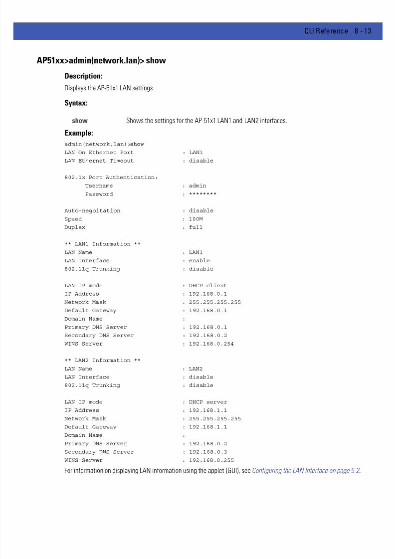
7/18/2019 Motorola AP 5131 Manual
http://slidepdf.com/reader/full/motorola-ap-5131-manual 283/613
CLI Reference 8 - 13
AP51xx>admin(network.lan)> show
Description:
Displays the AP-51x1 LAN settings.
Syntax:
Example:
admin(network.lan)>show
LAN On Ethernet Port : LAN1
LAN Ethernet Timeout : disable
802.1x Port Authentication:
Username : admin
Password : ********
Auto-negoitation : disable
Speed : 100M
Duplex : full
** LAN1 Information **
LAN Name : LAN1
LAN Interface : enable
802.11q Trunking : disable
LAN IP mode : DHCP client
IP Address : 192.168.0.1Network Mask : 255.255.255.255
Default Gateway : 192.168.0.1
Domain Name :
Primary DNS Server : 192.168.0.1
Secondary DNS Server : 192.168.0.2
WINS Server : 192.168.0.254
** LAN2 Information **
LAN Name : LAN2
LAN Interface : disable
802.11q Trunking : disable
LAN IP mode : DHCP server
IP Address : 192.168.1.1
Network Mask : 255.255.255.255
Default Gateway : 192.168.1.1
Domain Name :
Primary DNS Server : 192.168.0.2
Secondary DNS Server : 192.168.0.3
WINS Server : 192.168.0.255
For information on displaying LAN information using the applet (GUI), see Configuring the LAN Interface on page 5-2 .
show Shows the settings for the AP-51x1 LAN1 and LAN2 interfaces.

7/18/2019 Motorola AP 5131 Manual
http://slidepdf.com/reader/full/motorola-ap-5131-manual 284/613
8 - 14 WiNG 4.4 AP-5131 Product Reference Guide
AP51xx>admin(network.lan)> set
Description:
Sets the LAN parameters for the LAN port.
Syntax:
Example:
admin(network.lan)>
admin(network.lan)>set lan 1 enable
admin(network.lan)>set name 1 engineering
admin(network.lan)>set ethernet-port-lan 1
admin(network.lan)>set timeout 45
admin(network.lan)>set trunking 1 disable
admin(network.lan)>set auto-negotiation disable
admin(network.lan)>set speed 100M
admin(network.lan)>set duplex full
admin(network.lan)>set dns 1 192.168.0.1
admin(network.lan)>set dns 2 192.168.0.2
admin(network.lan)>set wins 1 192.168.0.254
admin(network.lan)>set trunking disable
admin(network.lan)>set username phil
admin(network.lan)>set passwd ea0258c1
set lan <mode> Enables or disables the AP-51x1 LAN interface.name <idx-name > Defines the LAN name by index.ethernet-port-lan
<idx> Defines which LAN (LAN1 or LAN2) is active on the Ethernet port.
timeout <seconds> Sets the interval (in seconds) the AP-51x1 uses to terminate itsLAN interface if no activity is detected for the specified interval.
trunking <mode> Enables or disables 802.11q Trunking over the AP-51x1 LAN port.auto-negotiation
<mode> Enables or disables auto-negotiation for the access point LANport.
speed <mbps> Defines the access point LAN port speed as either 10 Mbps or 100Mbps.
duplex <mode> Defines the access port LAN port duplex as either half or full.username <name> Specifies the user name for 802.1x port authentication over the
LAN interface.passwd <password> The 0-32 character password for the username for the 802.1x port.ip-mode <ip> Defines the AP-51x1 LAN port IP mode.ipadr <ip> Sets the IP address used by the LAN port.mask <ip> Defines the IP address used for AP-51x1 LAN port network mask.dgw <ip> Sets the Gateway IP address used by the LAN port.domain <name> Specifies the domain name used by the AP-51x1 LAN port.dns <ip> Defines the IP address of the primary and secondary DNS servers
used by the LAN port.wins <ip> Defines the IP address of the WINS server used by the LAN port.

7/18/2019 Motorola AP 5131 Manual
http://slidepdf.com/reader/full/motorola-ap-5131-manual 285/613
CLI Reference 8 - 15
Related Commands:
For information on configuring the LAN using the applet (GUI), see Configuring the LAN Interface on page 5-2 .
show Shows the current settings for the AP-51x1 LAN port.

7/18/2019 Motorola AP 5131 Manual
http://slidepdf.com/reader/full/motorola-ap-5131-manual 286/613
8 - 16 WiNG 4.4 AP-5131 Product Reference Guide
8.3.1.1 Network LAN, Bridge Commands
AP51xx>admin(network.lan.bridge)>
Description:Displays the AP-51x1 Bridge submenu.
For an overview of the access point’s mesh networking options using the applet (GUI), see Configuring Mesh Networkingon page 9-1.
show Displays the mesh configuration parameters for the AP-51x1’s LANs.set Sets the mesh configuration parameters for the AP-51x1’s LANs.... Moves to the parent menu.
/ Goes to the root menu.save Saves the configuration to system flash.quit Quits the CLI and exits the session.

7/18/2019 Motorola AP 5131 Manual
http://slidepdf.com/reader/full/motorola-ap-5131-manual 287/613
CLI Reference 8 - 17
AP51xx>admin(network.lan.bridge)> show
Description:
Displays the mesh bridge configuration parameters for the AP-51x1’s LANs.
Syntax:
Example:
admin(network.lan.bridge)>show
** LAN1 Bridge Configuration **Bridge Priority :32768
Hello Time (seconds) :2
Message Age Time (seconds) :20Forward Delay Time (seconds) :15
Entry Ageout Time (seconds) :300
** LAN2 Bridge Configuration **Bridge Priority :32768
Hello Time (seconds) :2
Message Age Time (seconds) :20
Forward Delay Time (seconds) :15
Entry Ageout Time (seconds) :300
For an overview of the access point’s mesh networking options using the applet (GUI), see Configuring Mesh Networkingon page 9-1.
show Displays the mesh bridge
configuration parameters for the AP-51x1’s LANs.

7/18/2019 Motorola AP 5131 Manual
http://slidepdf.com/reader/full/motorola-ap-5131-manual 288/613
8 - 18 WiNG 4.4 AP-5131 Product Reference Guide
AP51xx>admin(network.lan.bridge)> set
Description:
Sets the mesh configuration parameters for the AP-51x1’s LANs.
Syntax:
Example:
admin(network.lan.bridge)>set priority 2 32768
admin(network.lan.bridge)>set hello 2 2
admin(network.lan.bridge)>set msgage 2 20
admin(network.lan.bridge)>set fwddelay 2 15
admin(network.lan.bridge)>set ageout 2 300
admin(network.lan.bridge)>show
** LAN1 Mesh Configuration **Bridge Priority :32768
Hello Time (seconds) :2Message Age Time (seconds) :20
Forward Delay Time (seconds) :15
Entry Ageout Time (seconds) :300
** LAN2 Mesh Configuration **Bridge Priority :32768
Hello Time (seconds) :2
Message Age Time (seconds) :20
Forward Delay Time (seconds) :15
Entry Ageout Time (seconds) :300
For an overview of the access point’s mesh networking options using the applet (GUI), see Configuring Mesh Networkingon page 9-1.
set priority <LAN-idx> <seconds> Sets bridge priority time in seconds (0-65535) for specifiedLAN.
hello <LAN-idx> <seconds> Sets bridge hello time in seconds (0-10) for specified LAN.msgage <LAN-idx> <seconds> Sets bridge message age time in seconds (6-40) for
specified LAN.fwddelay <LAN-idx> <seconds> Sets bridge forward delay time in seconds (4-30) for
specified LAN.ageout <LAN-idx> <seconds> Sets bridge forward table entry time in seconds (4-3600) for
specified LAN.

7/18/2019 Motorola AP 5131 Manual
http://slidepdf.com/reader/full/motorola-ap-5131-manual 289/613
CLI Reference 8 - 19
8.3.1.2 Network LAN, WLAN-Mapping Commands
AP51xx>admin(network.lan.wlan-mapping)>
Description:Displays the WLAN/Lan/Vlan Mapping submenu.
For an overview of the access point’s VLAN configuration options using the applet (GUI), see Configuring VLAN Support onpage 5-4 .
show Displays the VLAN list currently defined for the AP-51x1.set Sets the AP-51x1 VLAN configuration.create Creates a new AP-51x1 VLAN.edit Edits the properties of an existing AP-51x1 VLAN.delete Deletes a VLAN.lan-map Maps AP-51x1 existing WLANs to an enabled LAN.vlan-map Maps AP-51x1 existing WLANs to VLANs... Moves to the parent menu.
/ Goes to the root menu.save Saves the configuration to system flash.quit Quits the CLI and exits the session.
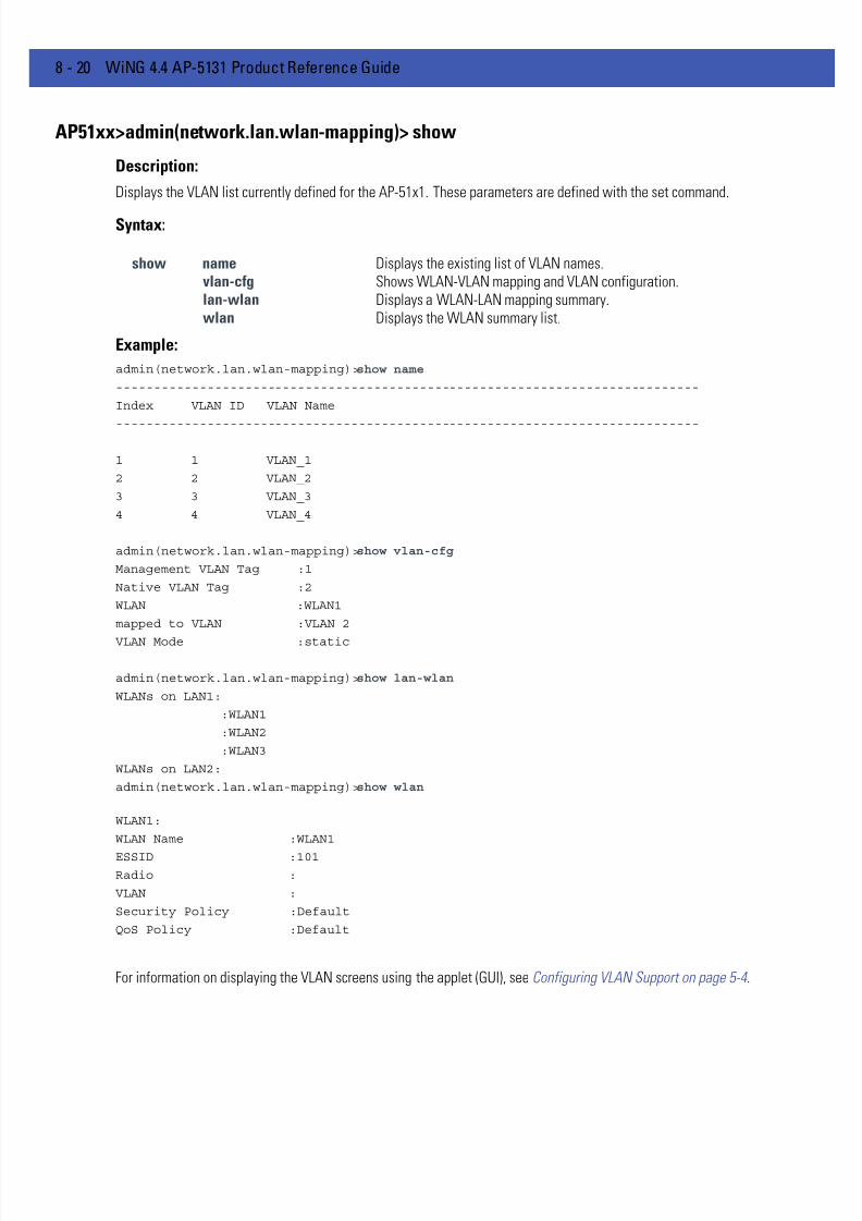
7/18/2019 Motorola AP 5131 Manual
http://slidepdf.com/reader/full/motorola-ap-5131-manual 290/613
8 - 20 WiNG 4.4 AP-5131 Product Reference Guide
AP51xx>admin(network.lan.wlan-mapping)> show
Description:
Displays the VLAN list currently defined for the AP-51x1. These parameters are defined with the set command.
Syntax:
Example:
admin(network.lan.wlan-mapping)>show name
-----------------------------------------------------------------------------
Index VLAN ID VLAN Name
-----------------------------------------------------------------------------
1 1 VLAN_1
2 2 VLAN_2
3 3 VLAN_3
4 4 VLAN_4
admin(network.lan.wlan-mapping)>show vlan-cfg
Management VLAN Tag :1
Native VLAN Tag :2
WLAN :WLAN1
mapped to VLAN :VLAN 2
VLAN Mode :static
admin(network.lan.wlan-mapping)>show lan-wlan
WLANs on LAN1:
:WLAN1
:WLAN2
:WLAN3
WLANs on LAN2:
admin(network.lan.wlan-mapping)>show wlan
WLAN1:
WLAN Name :WLAN1
ESSID :101Radio :
VLAN :
Security Policy :Default
QoS Policy :Default
For information on displaying the VLAN screens using the applet (GUI), see Configuring VLAN Support on page 5-4 .
show name Displays the existing list of VLAN names.vlan-cfg Shows WLAN-VLAN mapping and VLAN configuration.lan-wlan Displays a WLAN-LAN mapping summary.wlan Displays the WLAN summary list.

7/18/2019 Motorola AP 5131 Manual
http://slidepdf.com/reader/full/motorola-ap-5131-manual 291/613
CLI Reference 8 - 21
AP51xx>admin(network.lan.wlan-mapping)> set
Description:
Sets VLAN parameters for the AP-51x1.
Syntax:
Example:
admin(network.lan.wlan-mapping)>set mgmt-tag 1
admin(network.lan.wlan-mapping)>set native-tag 2
admin(network.lan.wlan-mapping)>set mode 1 static
admin(network.lan.wlan-mapping)>show vlan-cfg
Management VLAN Tag :1
Native VLAN Tag :2
WLAN :WLAN1
mapped to VLAN :VLAN 2
VLAN Mode :static
For information on configuring VLANs using the applet (GUI), see Configuring VLAN Support on page 5-4 .
set mgmt- tag <id> Defines the Management VLAN tag (1-4095).native-tag <id> Sets the Native VLAN tag (1-4095).mode <wlan-idx> Sets WLAN VLAN mode (WLAN 1-16) to either dynamic or static.

7/18/2019 Motorola AP 5131 Manual
http://slidepdf.com/reader/full/motorola-ap-5131-manual 292/613
8 - 22 WiNG 4.4 AP-5131 Product Reference Guide
AP51xx>admin(network.lan.wlan-mapping)> create
Description:
Creates a VLAN for the AP-51x1.
Syntax:
Example:
admin(network.lan.wlan-mapping)>
admin(network.lan.wlan-mapping)>create 5 vlan-5
For information on creating VLANs using the applet (GUI), see Configuring VLAN Support on page 5-4 .
create vlan-id <id> Defines the VLAN ID (1-4095).vlan-name <name> Specifies the name of the VLAN (1-31 characters in length).

7/18/2019 Motorola AP 5131 Manual
http://slidepdf.com/reader/full/motorola-ap-5131-manual 293/613
CLI Reference 8 - 23
AP51xx>admin(network.lan.wlan-mapping)> edit
Description:
Modifies a VLAN’s name and ID.
Syntax:
For information on editing VLANs using the applet (GUI), see Configuring VLAN Support on page 5-4 .
edit name <name> Modifies an exisiting VLAN name (1-31 characters in length)id <id> Modifies an existing VLAN ID (1-4095) characters in length).

7/18/2019 Motorola AP 5131 Manual
http://slidepdf.com/reader/full/motorola-ap-5131-manual 294/613
8 - 24 WiNG 4.4 AP-5131 Product Reference Guide
AP51xx>admin(network.lan.wlan-mapping)> delete
Description:
Deletes a specific VLAN or all VLANs.
Syntax:
For information on deleting VLANs using the applet (GUI), see Configuring VLAN Support on page 5-4 .
delete < VLAN id> Deletes a specific VLAN ID (1-16).all Deletes all defined VLANs.

7/18/2019 Motorola AP 5131 Manual
http://slidepdf.com/reader/full/motorola-ap-5131-manual 295/613
CLI Reference 8 - 25
AP51xx>admin(network.lan.wlan-mapping)> lan-map
Description:
Maps an AP-51x1 VLAN to a WLAN.
Syntax:
admin(network.lan.wlan-mapping)>lan-map wlan1 lan1
For information on mapping VLANs using the applet (GUI), see Configuring VLAN Support on page 5-4 .
lan-map <wlan name Maps an existing WLAN to an enabled LAN. All names and IDs arecase-sensitive.
<lan name> Defines enabled LAN name. All names and IDs are case-sensitive.

7/18/2019 Motorola AP 5131 Manual
http://slidepdf.com/reader/full/motorola-ap-5131-manual 296/613
8 - 26 WiNG 4.4 AP-5131 Product Reference Guide
AP51xx>admin(network.lan.wlan-mapping)> vlan-map
Description:
Maps an AP-51x1 VLAN to a WLAN.
Syntax:
admin(network.lan.wlan-mapping)>vlan-map wlan1 vlan1
For information on mapping VLANs using the applet (GUI), see Configuring VLAN Support on page 5-4 .
vlan-map <wlan name> Maps an existing WLAN to an enabled LAN. All names and IDs are case-sensitive.
<vlan name> Defines the existing VLAN name. All names and IDs are case-sensitive.

7/18/2019 Motorola AP 5131 Manual
http://slidepdf.com/reader/full/motorola-ap-5131-manual 297/613
CLI Reference 8 - 27
8.3.1.3 Network LAN, DHCP Commands
AP51xx>admin(network.lan.dhcp)>
Description:Displays the AP-51x1 DHCP submenu. The items available are displayed below.
show Displays DHCP parameters.set Sets DHCP parameters.add Adds static DHCP address assignments.delete Deletes static DHCP address assignments.list Lists static DHCP address assignments... Goes to the parent menu.
/ Goes to the root menu.save Saves the configuration to system flash.
quit Quits the CLI and exits the session.
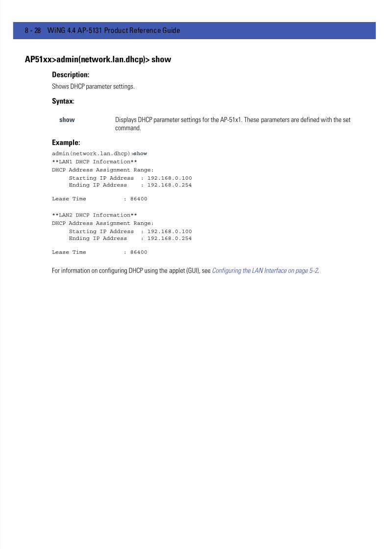
7/18/2019 Motorola AP 5131 Manual
http://slidepdf.com/reader/full/motorola-ap-5131-manual 298/613
8 - 28 WiNG 4.4 AP-5131 Product Reference Guide
AP51xx>admin(network.lan.dhcp)> show
Description:
Shows DHCP parameter settings.
Syntax:
Example:
admin(network.lan.dhcp)>show
**LAN1 DHCP Information**
DHCP Address Assignment Range:
Starting IP Address : 192.168.0.100Ending IP Address : 192.168.0.254
Lease Time : 86400
**LAN2 DHCP Information**
DHCP Address Assignment Range:
Starting IP Address : 192.168.0.100Ending IP Address : 192.168.0.254
Lease Time : 86400
For information on configuring DHCP using the applet (GUI), see Configuring the LAN Interface on page 5-2 .
show Displays DHCP parameter settings for the AP-51x1. These parameters are defined with the setcommand.

7/18/2019 Motorola AP 5131 Manual
http://slidepdf.com/reader/full/motorola-ap-5131-manual 299/613
CLI Reference 8 - 29
AP51xx>admin(network.lan.dhcp)> set
Description:
Sets DHCP parameters for the LAN port.
Syntax:
Example:
admin(network.lan.dhcp)>set range 1 192.168.0.100 192.168.0.254
admin(network.lan.dhcp)>set lease 1 86400
admin(network.lan.dhcp)>show
**LAN1 DHCP Information**
DHCP Address Assignment Range:
Starting IP Address : 192.168.0.100Ending IP Address : 192.168.0.254
Lease Time : 86400
For information on configuring DHCP using the applet (GUI), see Configuring the LAN Interface on page 5-2 .
set range <LAN-idx> <ip1> <ip2> Sets the DHCP assignment range from IP address<ip1> to IP address <ip2> for the specified LAN.
lease <LAN-idx> <lease> Sets the DHCP lease time <lease> in seconds (1-999999) for the specified LAN.

7/18/2019 Motorola AP 5131 Manual
http://slidepdf.com/reader/full/motorola-ap-5131-manual 300/613
8 - 30 WiNG 4.4 AP-5131 Product Reference Guide
AP51xx>admin(network.lan.dhcp)> add
Description:
Adds static DHCP address assignments.
Syntax:
Example:
admin(network.lan.dhcp)>add 1 00A0F8112233 192.160.24.6
admin(network.lan.dhcp)>add 1 00A0F1112234 192.169.24.7
admin(network.lan.dhcp)>list 1
-----------------------------------------------------------------------------
Index MAC Address IP Address
-----------------------------------------------------------------------------
1 00A0F8112233 192.160.24.6
2 00A0F8112234 192.169.24.7
For information on adding client MAC and IP address information using the applet (GUI), see Configuring Advanced DHCPServer Settings on page 5-10 .
add <LAN-idx> <mac> <ip> Adds a reserved static IP address to a MAC address for thespecified LAN
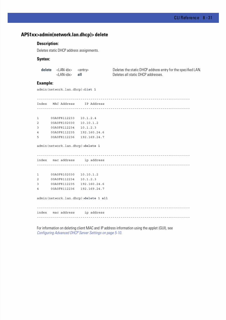
7/18/2019 Motorola AP 5131 Manual
http://slidepdf.com/reader/full/motorola-ap-5131-manual 301/613
CLI Reference 8 - 31
AP51xx>admin(network.lan.dhcp)> delete
Description:
Deletes static DHCP address assignments.
Syntax:
Example:
admin(network.lan.dhcp)>list 1
-----------------------------------------------------------------------------
Index MAC Address IP Address
-----------------------------------------------------------------------------
1 00A0F8112233 10.1.2.4
2 00A0F8102030 10.10.1.2
3 00A0F8112234 10.1.2.3
4 00A0F8112235 192.160.24.6
5 00A0F8112236 192.169.24.7
admin(network.lan.dhcp)>delete 1
-----------------------------------------------------------------------------
index mac address ip address
-----------------------------------------------------------------------------
1 00A0F8102030 10.10.1.2
2 00A0F8112234 10.1.2.3
3 00A0F8112235 192.160.24.6
4 00A0F8112236 192.169.24.7
admin(network.lan.dhcp)>delete 1 all
-----------------------------------------------------------------------------
index mac address ip address
-----------------------------------------------------------------------------
For information on deleting client MAC and IP address information using the applet (GUI), seeConfiguring Advanced DHCP Server Settings on page 5-10 .
delete <LAN-idx> <entry> Deletes the static DHCP address entry for the specified LAN.<LAN-idx> all Deletes all static DHCP addresses.

7/18/2019 Motorola AP 5131 Manual
http://slidepdf.com/reader/full/motorola-ap-5131-manual 302/613
8 - 32 WiNG 4.4 AP-5131 Product Reference Guide
AP51xx>admin(network.lan.dhcp)> list
Description:
Lists static DHCP address assignments.
Syntax:
Example:
admin(network.lan.dhcp)>list 1
-----------------------------------------------------------------------------
Index MAC Address IP Address
-----------------------------------------------------------------------------
1 00A0F8112233 10.1.2.4
2 00A0F8102030 10.10.1.2
3 00A0F8112234 10.1.2.3
4 00A0F8112235 192.160.24.6
5 00A0F8112236 192.169.24.7
admin(network.lan.dhcp)>
For information on listing client MAC and IP address information using the applet (GUI), see
Configuring Advanced DHCP Server Settings on page 5-10 .
list <LAN-idx> <cr> Lists the static DHCP address assignments for the specified LAN (1-LAN1, 2LAN2).

7/18/2019 Motorola AP 5131 Manual
http://slidepdf.com/reader/full/motorola-ap-5131-manual 303/613
CLI Reference 8 - 33
8.3.1.4 Network Type Filter Commands
AP51xx>admin(network.lan.type-filter)>
Description:Displays the AP-51x1 Type Filter submenu. The items available under this command include:
e
show Displays the current Ethernet Type exception list.set Defines Ethernet Type Filter parameters.add Adds an Ethernet Type Filter entry.delete Removes an Ethernet Type Filter entry... Goes to the parent menu.
/ Goes to the root menu.save Saves the configuration to system flash.quit Quits the CLI.

7/18/2019 Motorola AP 5131 Manual
http://slidepdf.com/reader/full/motorola-ap-5131-manual 304/613
8 - 34 WiNG 4.4 AP-5131 Product Reference Guide
AP51xx>admin(network.lan.type-filter)> show
Description:
Displays the AP-51x1’s current Ethernet Type Filter configuration.
Syntax:
Example:
admin(network.lan.type-filter)>show 1
Ethernet Type Filter mode : allow
-----------------------------------------------------------------------------
index ethernet type
-----------------------------------------------------------------------------
1 8137
For information on displaying the type filter configuration using the applet, see Setting the Type Filter Configuration onpage 5-10 .
show <LAN-idx> Displays the existing Type-Filter configuration for the specified LAN.
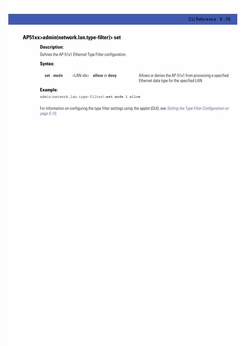
7/18/2019 Motorola AP 5131 Manual
http://slidepdf.com/reader/full/motorola-ap-5131-manual 305/613
CLI Reference 8 - 35
AP51xx>admin(network.lan.type-filter)> set
Description:
Defines the AP-51x1 Ethernet Type Filter configuration.
Syntax:
Example:
admin(network.lan.type-filter)>set mode 1 allow
For information on configuring the type filter settings using the applet (GUI), see Setting the Type Filter Configuration onpage 5-10 .
set mode <LAN-idx> allow or deny Allows or denies the AP-51x1 from processing a specifiedEthernet data type for the specified LAN.

7/18/2019 Motorola AP 5131 Manual
http://slidepdf.com/reader/full/motorola-ap-5131-manual 306/613
8 - 36 WiNG 4.4 AP-5131 Product Reference Guide
AP51xx>admin(network.lan.type-filter)> add
Description:
Adds an Ethernet Type Filter entry.
Syntax:
Example:
admin(network.lan.type-filter)>
admin(network.wireless.type-filter)>add 1 8137
admin(network.wireless.type-filter)>add 2 0806
admin(network.wireless.type-filter)>show 1
Ethernet Type Filter mode : allow
-----------------------------------------------------------------------------
index ethernet type
-----------------------------------------------------------------------------
1 8137
2 0806
3 0800
4 8782
For information on configuring the type filter settings using the applet (GUI), see Setting the Type Filter Configuration onpage 5-10 .
add <LAN-idx> <type> Adds entered Ethernet Type to list of data types either allowed or deniedAP-51x1 processing permissions for the specified LAN (either LAN1 orLAN2).

7/18/2019 Motorola AP 5131 Manual
http://slidepdf.com/reader/full/motorola-ap-5131-manual 307/613
CLI Reference 8 - 37
AP51xx>admin(network.lan.type-filter)> delete
Description:
Removes an Ethernet Type Filter entry individually or the entire Type Filter list.
Syntax:
Example:
admin(network.lan.type-filter)>delete 1 1
admin(network.lan.type-filter)>show 1
Ethernet Type Filter mode : allow
-----------------------------------------------------------------------------
index ethernet type-----------------------------------------------------------------------------
1 0806
2 0800
3 8782
admin(network.lan.type-filter)>delete 2 all
admin(network.lan.type-filter)>show 2
Ethernet Type Filter mode : allow
-----------------------------------------------------------------------------
index ethernet type
-----------------------------------------------------------------------------
For information on configuring the type filter settings using the applet (GUI), see Setting the Type Filter Configuration onpage 5-10 .
delete <LAN-idx> <index> Deletes the specified Ethernet Type index entry (1 through 16).<LAN-idx> all Deletes all Ethernet entries currently in list.

7/18/2019 Motorola AP 5131 Manual
http://slidepdf.com/reader/full/motorola-ap-5131-manual 308/613
8 - 38 WiNG 4.4 AP-5131 Product Reference Guide
8.3.2 Network WAN Commands
AP51xx>admin(network.wan)>
Description:Displays the WAN submenu. The items available under this command are shown below.
For an overview of the WAN configuration options using the applet (GUI), see Configuring WAN Settings on page 5-13 .
show Displays the AP-51x1 WAN configuration and the AP-51x1’s current PPPoE configuration.set Defines the AP-51x1’s WAN and PPPoE configuration.nat Displays the NAT submenu, wherein Network Address Translations (NAT) can be defined.vpn Goes to the VPN submenu, where the AP-51x1 VPN tunnel configuration can be set.content Goes to the outbound content filtering menu.dyndns Displays the Dynamic DNS submenu, wherein dyndns settings can be defined... Goes to the parent menu.
/ Goes to the root menu.
save Saves the current configuration to the AP-51x1 system flash.quit Quits the CLI and exits the current session.

7/18/2019 Motorola AP 5131 Manual
http://slidepdf.com/reader/full/motorola-ap-5131-manual 309/613
CLI Reference 8 - 39
AP51xx>admin(network.wan)> show
Description:
Displays the AP-51x1 WAN port parameters.
Syntax:
Example:
admin(network.wan)>show
Status : enable
Primary DNS Server : 0.0.0.0
Secondary DNS Server : 0.0.0.0
Auto-negotiation : disable
Speed : 100M
Duplex : full
WAN IP 2 : disable
WAN IP 3 : disable
WAN IP 4 : disable
WAN IP 5 : disable
WAN IP 6 : disable
WAN IP 7 : disable
WAN IP 8 : disable
PPPoE Mode : enable
PPPoE User Name : JohnDoe
PPPoE Password : *******
PPPoE keepalive mode : enable
PPPoE Idle Time : 600
PPPoE Authentication Type : chap
PPPoE State
admin(network.wan)>
For an overview of the WAN configuration options available using the applet (GUI), see
Configuring WAN Settings on page 5-13 .
show Shows the general IP parameters for the WAN port along with settings for the WAN interface..
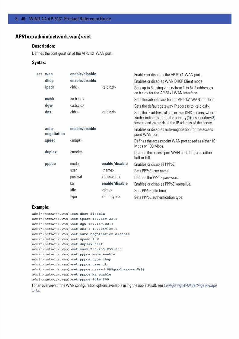
7/18/2019 Motorola AP 5131 Manual
http://slidepdf.com/reader/full/motorola-ap-5131-manual 310/613
8 - 40 WiNG 4.4 AP-5131 Product Reference Guide
AP51xx>admin(network.wan)> set
Description:
Defines the configuration of the AP-51x1 WAN port.
Syntax:
Example:
admin(network.wan)>set dhcp disable
admin(network.wan)>set ipadr 157.169.22.5
admin(network.wan)>set dgw 157.169.22.1
admin(network.wan)>set dns 1 157.169.22.2
admin(network.wan)>set auto-negotiation disable
admin(network.wan)>set speed 10M
admin(network.wan)>set duplex half
admin(network.wan)>set mask 255.255.255.000
admin(network.wan)>set pppoe mode enable
admin(network.wan)>set pppoe type chap
admin(network.wan)>set pppoe user jk
admin(network.wan)>set pppoe passwd @#$goodpassword%$#
admin(network.wan)>set pppoe ka enable
admin(network.wan)>set pppoe idle 600
For an overview of the WAN configuration options available using the applet (GUI), see Configuring WAN Settings on page5-13 .
set wan enable /disable Enables or disables the AP-51x1 WAN port.
dhcp enable /disable Enables or disables WAN DHCP Client mode.
ipadr <idx> <a.b.c.d> Sets up to 8 (using <indx> from 1 to 8) IP addresses<a.b.c.d> for the AP-51x1 WAN interface.
mask <a.b.c.d> Sets the subnet mask for the AP-51x1 WAN interface.
dgw <a.b.c.d> Sets the default gateway IP address to <a.b.c.d>.
dns <idx> <a.b.c.d> Sets the IP address of one or two DNS servers, where
<indx> indicates either the primary (1) or secondary (2)server, and <a.b.c.d> is the IP address of the server.
auto-negotiation
enable /disable Enables or disables auto-negotiation for the accesspoint WAN port.
speed <mbps> Defines the access point WAN port speed as either 10Mbps or 100 Mbps.
duplex <mode> Defines the access port WAN port duplex as eitherhalf or full.
pppoe mode enable /disable Enables or disables PPPoE.
user <name> Sets PPPoE user name.
passwd <password> Defines the PPPoE password.ka enable /disable Enables or disables PPPoE keepalive.
idle <time> Sets PPPoE idle time.
type <auth-type> Sets PPPoE authentication type.
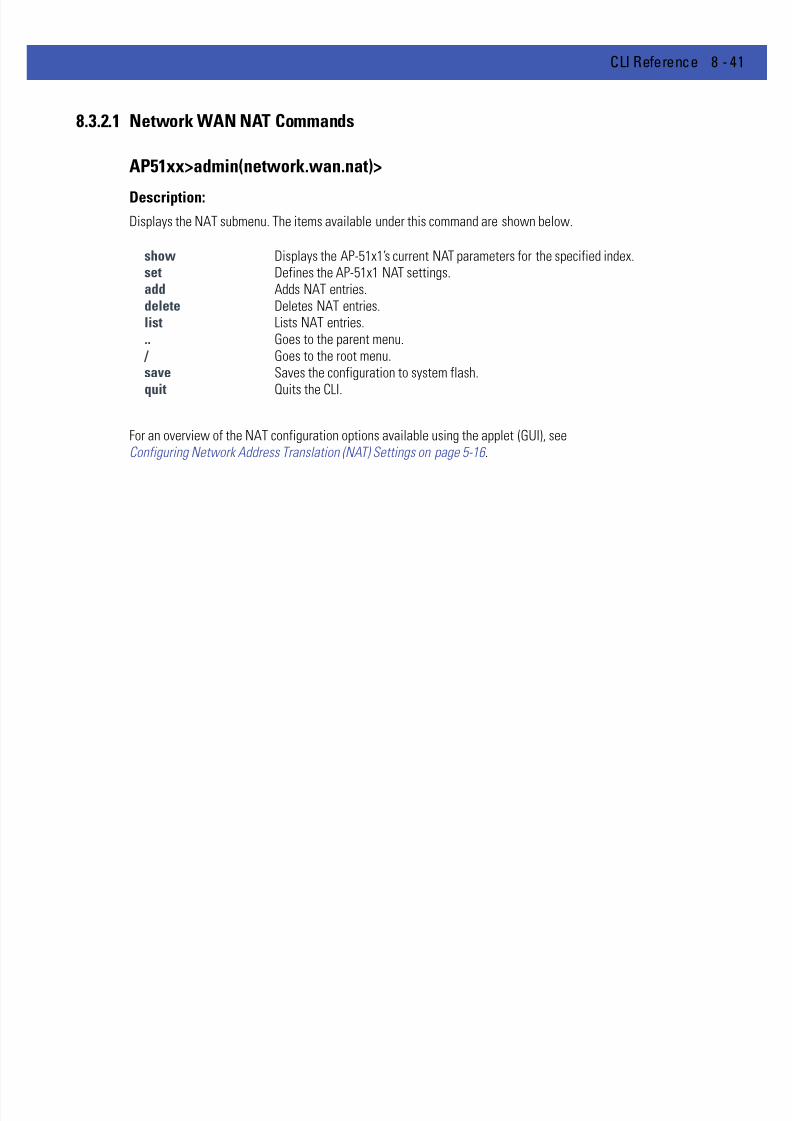
7/18/2019 Motorola AP 5131 Manual
http://slidepdf.com/reader/full/motorola-ap-5131-manual 311/613
CLI Reference 8 - 41
8.3.2.1 Network WAN NAT Commands
AP51xx>admin(network.wan.nat)>
Description:Displays the NAT submenu. The items available under this command are shown below.
For an overview of the NAT configuration options available using the applet (GUI), seeConfiguring Network Address Translation (NAT) Settings on page 5-16 .
show Displays the AP-51x1’s current NAT parameters for the specified index.set Defines the AP-51x1 NAT settings.add Adds NAT entries.delete Deletes NAT entries.list Lists NAT entries... Goes to the parent menu.
/ Goes to the root menu.save Saves the configuration to system flash.
quit Quits the CLI.

7/18/2019 Motorola AP 5131 Manual
http://slidepdf.com/reader/full/motorola-ap-5131-manual 312/613
8 - 42 WiNG 4.4 AP-5131 Product Reference Guide
AP51xx>admin(network.wan.nat)> show
Description:
Displays AP-51x1 NAT parameters.
Syntax:
Example:
admin(network.wan.nat)>show 2
WAN IP Mode : enable
WAN IP Address : 157.235.91.2
NAT Type : 1-to-many
One to many nat mapping : LAN1 LAN2
Inbound Mappings : Port Forwarding
unspecified port forwarding mode : enable
unspecified port fwd. ip address : 111.223.222.1
one to many nat mapping
-------------------------------------------------------------------------------LAN No. WAN IP-------------------------------------------------------------------------------
1 157.235.91.2
2 157.235.91.2
admin(network.wan.nat)>
For an overview of the NAT options available using the applet (GUI), see Configuring Network Address Translation (NAT)Settings on page 5-16 .
show <idx> <cr> Displays AP-51x1 NAT parameters for the specified NAT index.
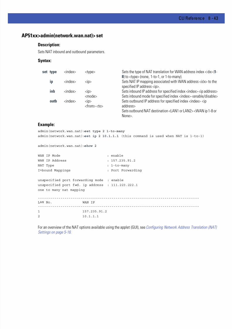
7/18/2019 Motorola AP 5131 Manual
http://slidepdf.com/reader/full/motorola-ap-5131-manual 313/613
CLI Reference 8 - 43
AP51xx>admin(network.wan.nat)> set
Description:
Sets NAT inbound and outbound parameters.
Syntax:
Example:
admin(network.wan.nat)>set type 2 1-to-many
admin(network.wan.nat)>set ip 2 10.1.1.1 (this command is used when NAT is 1-to-1)
admin(network.wan.nat)>show 2
WAN IP Mode : enable
WAN IP Address : 157.235.91.2
NAT Type : 1-to-many
Inbound Mappings : Port Forwarding
unspecified port forwarding mode : enable
unspecified port fwd. ip address : 111.223.222.1
one to many nat mapping
-------------------------------------------------------------------------------LAN No. WAN IP-------------------------------------------------------------------------------
1 157.235.91.2
2 10.1.1.1
For an overview of the NAT options available using the applet (GUI), see Configuring Network Address Translation (NAT)Settings on page 5-16 .
set type <index> <type> Sets the type of NAT translation for WAN address index <idx> (1-8) to <type> (none, 1-to-1, or 1-to-many).
ip <index> <ip> Sets NAT IP mapping associated with WAN address <idx> to thespecified IP address <ip>.
inb <index> <ip><mode>
Sets inbound IP address for specified index <index> <ip address>Sets inbound mode for specified index <index> <enable/disable>
outb <index> <ip><from> <to>
Sets outbound IP address for specified index <index> <ipaddress>Sets outbound NAT destination <LAN1 or LAN2> <WAN ip 1-8 or
None>.

7/18/2019 Motorola AP 5131 Manual
http://slidepdf.com/reader/full/motorola-ap-5131-manual 314/613
8 - 44 WiNG 4.4 AP-5131 Product Reference Guide
AP51xx>admin(network.wan.nat)> add
Description:
Adds NAT entries.
Syntax:
Example:
admin(network.wan.nat)>add 1 indoors udp 20 29 10.10.2.2
admin(network.wan.nat)>list 1
-----------------------------------------------------------------------------
index name prot start port end port internal ip translation port
-----------------------------------------------------------------------------
1 indoor udp 20 29 10.10.2.2 0
Related Commands:
For an overview of the NAT options available using the applet (GUI), see Configuring Network Address Translation (NAT)Settings on page 5-16 .
add <idx> <name> <tran> <port1> <port2> <ip> <dst_port>
Sets an inbound network address translation (NAT) for WAN address <idx>, where <name> is thename of the entry (1 to 7 characters), <tran> is the transport protocol (one of tcp, udp, icmp, ah,esp, gre, or all), <port1> is the starting port number in a port range, <port2> is the ending portnumber in a port range, <ip> is the internal IP address, and <dst_port> is the (optional) internaltranslation port.
delete Deletes one of the inbound NAT entries from the list.list Displays the list of inbound NAT entries.

7/18/2019 Motorola AP 5131 Manual
http://slidepdf.com/reader/full/motorola-ap-5131-manual 315/613
CLI Reference 8 - 45
AP51xx>admin(network.wan.nat)> delete
Description:
Deletes NAT entries.
Syntax:
Example:
admin(network.wan.nat)>list 1
-----------------------------------------------------------------------------
index name prot start port end port internal ip translation port
-----------------------------------------------------------------------------
1 special tcp 20 21 192.168.42.16 21
admin(network.wan.nat)>delete 1 1
^
admin(network.wan.nat)>list 1
-----------------------------------------------------------------------------
index name prot start port end port internal ip translation port
-----------------------------------------------------------------------------
Related Commands:
For an overview of the NAT options available using the applet (GUI), see Configuring Network Address Translation (NAT)Settings on page 5-16 .
delete <idx> <entry> Deletes a specified NAT index entry <entry> associated with the WAN.<idx> all Deletes all NAT entries associated with the WAN.
add Adds entries to the list of inbound NAT entries.list Displays the list of inbound NAT entries.

7/18/2019 Motorola AP 5131 Manual
http://slidepdf.com/reader/full/motorola-ap-5131-manual 316/613
8 - 46 WiNG 4.4 AP-5131 Product Reference Guide
AP51xx>admin(network.wan.nat)> list
Description:
Lists AP-51x1 NAT entries for the specified index.
Syntax:
Example:
admin(network.wan.nat)>list 1
-----------------------------------------------------------------------------
index name Transport start port end port internal ip translation port
-----------------------------------------------------------------------------
1 special tcp 20 21 192.168.42.16 21
Related Commands: 1
For an overview of the NAT options available using the applet (GUI), see Configuring Network Address Translation (NAT)Settings on page 5-16 .
list <idx> Lists the inbound NAT entries associated with the WAN index (1-8).
delete Deletes inbound NAT entries from the list.add Adds entries to the list of inbound NAT entries.

7/18/2019 Motorola AP 5131 Manual
http://slidepdf.com/reader/full/motorola-ap-5131-manual 317/613
CLI Reference 8 - 47
8.3.2.2 Network WAN, VPN Commands
AP51xx>admin(network.wan.vpn)>
Description:Displays the VPN submenu. The items available under this command include:
For an overview of the VPN options available using the applet (GUI), see Configuring VPN Tunnels on page 6-32 .
add Adds VPN tunnel entries.set Sets key exchange parameters.delete Deletes VPN tunnel entries.list Lists VPN tunnel entriesreset Resets all VPN tunnels.stats Lists security association status for the VPN tunnels.ikestate Displays an Internet Key Exchange (IKE) summary... Goes to the parent menu.
/ Goes to the root menu.save Saves the configuration to system flash.quit Quits the CLI.

7/18/2019 Motorola AP 5131 Manual
http://slidepdf.com/reader/full/motorola-ap-5131-manual 318/613
8 - 48 WiNG 4.4 AP-5131 Product Reference Guide
AP51xx>admin(network.wan.vpn)> add
Description:
Adds a VPN tunnel entry.
Syntax:
Example:
admin(network.wan.vpn)>add 2 SJSharkey 209.235.44.31 206.107.22.46 255.255.255.224206.107.22.1
If tunnel type is Manual, proper SPI values and Keys must be configured after adding thetunnel
admin(network.wan.vpn)>
For information on configuring VPN using the applet (GUI), see Configuring VPN Tunnels on page 6-32 .
add <name> <idx> <LWanIP> <RSubnetIP> <RSubnetMask <RGatewayIP>
Creates a tunnel <name> (1 to 13 characters) to gain access through local WAN IP <LWanIP> fromthe remote subnet with address <RSubnetIP> and subnet mask <RSubnetMask> using the remotegateway <RGatewayIP>.

7/18/2019 Motorola AP 5131 Manual
http://slidepdf.com/reader/full/motorola-ap-5131-manual 319/613
CLI Reference 8 - 49
AP51xx>admin(network.wan.vpn)> set
Description:
Sets VPN entry parameters.
Syntax:
set type <name> <tunnel type> Sets the tunnel type <name> to Auto or Manuafor the specified tunnel name.
authalgo <name> <authalgo> Sets the authentication algorithm for <name> to(None, MD5, or SHA1).
authkey <name> <dir> <authkey> Sets the AH authentication key (if type isManual) for tunnel <name> with the direction seto IN or OUT, and the manual authentication keyset to <authkey>. (The key size is 32 hex
characters for MD5, and 40 hex characters forSHA1).
esp-type <name> <esptype> Sets the Encapsulating Security Payload (ESP)type. Options include None, ESP, or ESP-AUTH
esp-encalgo <name> <escalgo> Sets the ESP encryption algorithm. Optionsinclude DES, 3DES, AES128, AES192, orAES256).
esp-enckey <name> <dir> <enckey> Sets the Manual Encryption Key in ASCII fortunnel <name> and direction IN or OUT to the key<enc-key>. The size of the key depends on theencryption algorithm.
- 16 hex characters for DES- 48 hex characters for 3DES- 32 hex characters for AES128- 48 hex characters for AES192- 64 hex characters for AES256
esp-authalgo <name> <authalgo> Sets the ESP authentication algorithm. Optionsinclude MD5 or SHA1.
esp-authkey <name> <dir> <authkey> Sets ESP Authentication key <name> either forIN or OUT direction to <auth-key>, an ASCIIstring of hex characters. If authalgo is set toMD5, then provide 32 hex characters. If authalgo
is set to SHA1, provide 40 hex characters.spi <name> <algo> <dir> <value> Sets 6 character IN(bound) or OUT(bound) for
AUTH (Manual Authentication) or ESP for<name> to <spi> (a hex value more than 0xFF)<value>.
usepfs <name> <mode> Enables or disables Perfect Forward Secrecy for<name>.
salife <name> <lifetime> Defines the name of the tunnnel <name> theSecurity Association Life Time <300-65535>applies to in seconds.

7/18/2019 Motorola AP 5131 Manual
http://slidepdf.com/reader/full/motorola-ap-5131-manual 320/613
8 - 50 WiNG 4.4 AP-5131 Product Reference Guide
For information on configuring VPN using the applet (GUI), see Configuring VPN Tunnels on page 6-32 .
ike opmode <name> <opmode> Sets the Operation Mode of IKE for <name> toMain or Aggr(essive).
myidtype <name> <idtype> Sets the Local ID type for IKE authentication for<name> (1 to 13 characters) to <idtype> (IP,
FQDN, or UFQDN).remidtype <name> <idtype> Sets the Remote ID type for IKE authentication for
<name> (1 to 13 characters) to <idtype> (IP,FQDN, or UFQDN).
myiddata <name> <idtype> Sets the Local ID data for IKE authentication for<name> to <idtype>. This value is not requiredwhen the ID type is set to IP.
remiddata <name> <idtype> Sets the Local ID data for IKE authentication for<name> to <idtype>. This value is not requiredwhen the ID type is set to IP.
authtype <name> <authtype> Sets the IKE Authentication type for <name> to<authtype> ( PSK or RSA).
authalgo <name> <authalgo> Sets the IKE Authentication Algorithm for<name> to MD5 or SHA1.
phrase <name> <phrase> Sets the IKE Authentication passphrase for<name> to <phrase>.
encalgo <name> <encalgo> Sets the IKE Encryption Algorithm for <name> to<encalgo> (one of DES, 3DES, AES128, AES192,or AES256).
lifetime <name> <lifetime> Sets the IKE Key life time in seconds for <name>to <lifetime>.
group <name> <group> Sets the IKE Diffie-Hellman Group for <name> toeither G768 or G1024.

7/18/2019 Motorola AP 5131 Manual
http://slidepdf.com/reader/full/motorola-ap-5131-manual 321/613
CLI Reference 8 - 51
AP51xx>admin(network.wan.vpn)> delete
Description:
Deletes VPN tunnel entries.
Syntax:
Example:
admin(network.wan.vpn)>list
--------------------------------------------------------------------------
Tunnel Name Type Remote IP/Mask Remote Gateway Local WAN IP
--------------------------------------------------------------------------
Eng2EngAnnex Manual 192.168.32.2/24 192.168.33.1 192.168.24.198
SJSharkey Manual 206.107.22.45/27 206.107.22.2 209.235.12.55
admin(network.wan.vpn)>delete Eng2EngAnnex
admin(network.wan.vpn)>list
--------------------------------------------------------------------------
Tunnel Name Type Remote IP/Mask Remote Gateway Local WAN IP
--------------------------------------------------------------------------
SJSharkey Manual 206.107.22.45/27 206.107.22.2 209.235.12.55
admin(network.wan.vpn)>
For information on configuring VPN using the applet (GUI), see Configuring VPN Tunnels on page 6-32 .
delete all Deletes all VPN entries.<name> Deletes VPN entries <name>.

7/18/2019 Motorola AP 5131 Manual
http://slidepdf.com/reader/full/motorola-ap-5131-manual 322/613
8 - 52 WiNG 4.4 AP-5131 Product Reference Guide
AP51xx>admin(network.wan.vpn)> list
Description:
Lists VPN tunnel entries.
Syntax:
Example:
admin(network.wan.vpn)>list
--------------------------------------------------------------------------
Tunnel Name Type Remote IP/Mask Remote Gateway Local WAN IP
--------------------------------------------------------------------------Eng2EngAnnex Manual 192.168.32.2/24 192.168.33.1 192.168.24.198
SJSharkey Manual 206.107.22.45/27 206.107.22.2 209.235.12.55
admin(network.wan.vpn)>list SJSharkey
--------------------------------------------------------------------------
Detail listing of VPN entry:
--------------------------------------------------------------------------
Name : SJSharkey
Local Subnet : 1
Tunnel Type : Manual
Remote IP : 206.107.22.45
Remote IP Mask : 255.255.255.224Remote Security Gateway : 206.107.22.2
Local Security Gateway : 209.239.160.55
AH Algorithm : None
Encryption Type : ESP
Encryption Algorithm : DES
ESP Inbound SPI : 0x00000100
ESP Outbound SPI : 0x00000100
For information on displaying VPN information using the applet (GUI), see Viewing VPN Status on page 6-42 .
list <cr> Lists all tunnel entries.
<name> Lists detailed information about tunnel named <name>. Note that the<name> must match case with the name of the VPN tunnel entry
7/18/2019 Motorola AP 5131 Manual
http://slidepdf.com/reader/full/motorola-ap-5131-manual 323/613
CLI Reference 8 - 53
AP51xx>admin(network.wan.vpn)> reset
Description:
Resets all of the AP-51x1’s VPN tunnels.
Syntax:
Example:
admin(network.wan.vpn)>reset
VPN tunnels reset.
admin(network.wan.vpn)>
For information on configuring VPN using the applet (GUI), see Configuring VPN Tunnels on page 6-32 .
reset Resets all VPN tunnel states.

7/18/2019 Motorola AP 5131 Manual
http://slidepdf.com/reader/full/motorola-ap-5131-manual 324/613
8 - 54 WiNG 4.4 AP-5131 Product Reference Guide
AP51xx>admin(network.wan.vpn)> stats
Description:
Lists statistics for all active tunnels.
Syntax:
Example:
admin(network.wan.vpn)>stats
-----------------------------------------------------------------------------
Tunnel Name Status SPI(OUT/IN) Life Time Bytes(Tx/Rx)
-----------------------------------------------------------------------------
Eng2EngAnnex Not Active
SJSharkey Not Active
For information on displaying VPN information using the applet (GUI), see Viewing VPN Status on page 6-42 .
stats Display statistics for all VPN tunnels.

7/18/2019 Motorola AP 5131 Manual
http://slidepdf.com/reader/full/motorola-ap-5131-manual 325/613
CLI Reference 8 - 55
AP51xx>admin(network.wan.vpn)> ikestate
Description:
Displays statistics for all active tunnels using Internet Key Exchange (IKE).
Syntax:
Example:
admin(network.wan.vpn)>ikestate
----------------------------------------------------------------------
Tunnel Name IKE State Dest IP Remaining Life
----------------------------------------------------------------------
Eng2EngAnnex Not Connected ---- ---
SJSharkey Not Connected ---- ---
admin(network.wan.vpn)>
For information on configuring IKE using the applet (GUI), see Configuring IKE Key Settings on page 6-40 .
ikestate Displays status about Internet Key Exchange (IKE) for all tunnels. In particular, the table indicateswhether IKE is connected for any of the tunnels, it provides the destination IP address, and theremaining lifetime of the IKE key.

7/18/2019 Motorola AP 5131 Manual
http://slidepdf.com/reader/full/motorola-ap-5131-manual 326/613
8 - 56 WiNG 4.4 AP-5131 Product Reference Guide
8.3.2.3 Network WAN, Outbound Content Filtering Commands
AP51xx>admin(network.wan.content)>
Description:Displays the Outbound Content Filtering menu. The items available under this command include:
addcmd Adds control commands to block outbound traffic.delcmd Deletes control commands to block outbound traffic.list Lists application control commands... Goes to the parent menu.
/ Goes to the root menu.save Saves the configuration to system flash.quit Quits the CLI.
7/18/2019 Motorola AP 5131 Manual
http://slidepdf.com/reader/full/motorola-ap-5131-manual 327/613
CLI Reference 8 - 57
AP51xx>admin(network.wan.content)> addcmd
Description:
Adds control commands to block outbound traffic.
Syntax:
Example:
admin(network.wan.content)>addcmd web proxy
admin(network.wan.content)>addcmd smtp data
admin(network.wan.content)>addcmd ftp put
addcmd web Adds WEB commands to block outbound traffic.proxy Adds a Web proxy command.activex Adds activex files.file Adds Web URL extensions (10 files maximum)
smtp Adds SMTP commands to block outbound traffic.helo helo commandmail mail commandrcpt rcpt commanddata data command
quit quit commandsend send commandsaml saml commandreset reset commandvrfy vrfy commandexpn expn command
ftp Adds FTP commands to block outbound traffic.put store commandget retreive commandls directory list commandmkdir create directory commandcd change directory commandpasv passive mode command

7/18/2019 Motorola AP 5131 Manual
http://slidepdf.com/reader/full/motorola-ap-5131-manual 328/613
8 - 58 WiNG 4.4 AP-5131 Product Reference Guide
AP51xx>admin(network.wan.content)> delcmd
Description:
Deletes control commands to block outbound traffic.
Syntax:
Example:
admin(network.wan.content)>delcmd web proxy
admin(network.wan.content)>delcmd smtp data
admin(network.wan.content)>delcmd ftp put
delcmd web Deletes WEB commands to block outbound traffic.proxy Deletes a Web proxy command.activex Deletes activex files.file Deletes Web URL extensions (10 files maximum)
smtp Deletes SMTP commands to block outbound traffic.helo helo commandmail mail commandrcpt rcpt commanddata data command
quit quit commandsend send commandsaml saml commandreset reset commandvrfy vrfy commandexpn expn command
ftp Deletes FTP commands to block outbound traffic.put store commandget retreive commandls directory list commandmkdir create directory commandcd change directory commandpasv passive mode command
7/18/2019 Motorola AP 5131 Manual
http://slidepdf.com/reader/full/motorola-ap-5131-manual 329/613
CLI Reference 8 - 59
AP51xx>admin(network.wan.content)> list
Description:
Lists application control commands.
Syntax:
Example:
admin(network.wan.content)>list web
HTTP Files/Commands
Web Proxy : deny
ActiveX : allowfilename :
admin(network.wan.content)>list smtp
SMTP Commands
HELO : deny
MAIL : allow
RCPT : allow
DATA : deny
QUIT : allow
SEND : allow
SAML : allow
RESET : allow
VRFY : allow
EXPN : allow
admin(network.wan.content)>list ftp
FTP Commands
Storing Files : deny
Retreiving Files : allow
Directory Files : allow
Create Directory : allow
Change Directory : allow
Passive Operation : allow
list web Lists WEB application control record.smtp Lists SMTP application control record.ftp Lists FTP application control record.

7/18/2019 Motorola AP 5131 Manual
http://slidepdf.com/reader/full/motorola-ap-5131-manual 330/613
8 - 60 WiNG 4.4 AP-5131 Product Reference Guide
8.3.2.4 Network WAN, Dynamic DNS Commands
AP51xx>admin(network.wan.dyndns)>
Description:Displays the Dynamic DNS submenu. The items available under this command include:
For an overview of the Dynamic DNS options available using the applet (GUI), see Configuring Dynamic DNS on page 5-19 .
set Sets Dynamic DNS parameters.update Sets key exchange parameters.show Shows the Dynamic DNS configuration... Goes to the parent menu.
/ Goes to the root menu.save Saves the configuration to system flash.quit Quits the CLI.

7/18/2019 Motorola AP 5131 Manual
http://slidepdf.com/reader/full/motorola-ap-5131-manual 331/613
CLI Reference 8 - 61
AP51xx>admin(network.wan.dyndns)> set
Description:
Sets the access point’s Dynamic DNS configuration.
Syntax:
Example:admin(network.wan.dyndns)>set mode enable
admin(network.wan.dyndns)>set username percival
admin(network.wan.dyndns)>set password mudskipper
admin(network.wan.dyndns)>set host greengiant
For an overview of the Dynamic DNS options available using the applet (GUI), see Configuring Dynamic DNS on page 5-19 .
set mode enable/disable Enables or disbales the Dynamic DNS service for the access point.
username <name> Enter a 1 - 32 character username for the account used for the accesspoint.
password <password> Enter a 1 - 32 character password for the account used for the accesspoint.
hostname <host> Enter a 1 - 32 character hostname for the account used for the accesspoint.
7/18/2019 Motorola AP 5131 Manual
http://slidepdf.com/reader/full/motorola-ap-5131-manual 332/613
8 - 62 WiNG 4.4 AP-5131 Product Reference Guide
AP51xx>admin(network.wan.dyndns)> update
Description:
Updates the access point’s current WAN IP address with the DynDNS service.
Syntax:
Example:
admin(network.wan.dyndns)>update
IP Address : 157.235.91.231
Hostname : greengiant
For an overview of the Dynamic DNS options available using the applet (GUI), see Configuring Dynamic DNS on page 5-19 .
update Updates the access point’s current WAN IP address with the DynDNS service.

7/18/2019 Motorola AP 5131 Manual
http://slidepdf.com/reader/full/motorola-ap-5131-manual 333/613
CLI Reference 8 - 63
AP51xx>admin(network.wan.dyndns)> show
Description:
Shows the current Dynamic DNS configuration.
Syntax:
Example:
admin(network.wan.dyndns)>show
DynDNS Configuration
Mode : enable
Username : percival
Password : ********Hostname : greengiant
DynDNS Update Response
IP Address : 157.235.91.231
Hostname : greengiant
Status : OK
For an overview of the Dynamic DNS options available using the applet (GUI), see Configuring Dynamic DNS on page 5-19 .
show Shows the access point’s current Dynamic DNS configuration.
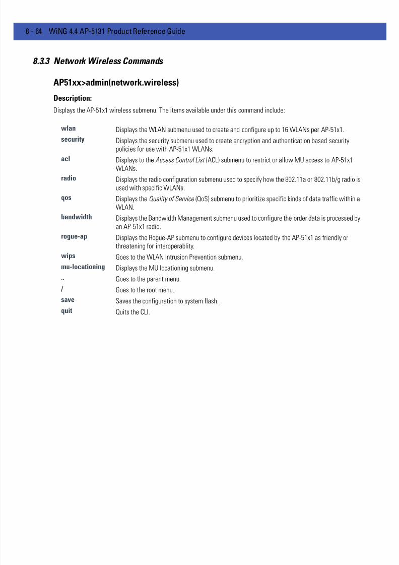
7/18/2019 Motorola AP 5131 Manual
http://slidepdf.com/reader/full/motorola-ap-5131-manual 334/613
8 - 64 WiNG 4.4 AP-5131 Product Reference Guide
8.3.3 Network Wireless Commands
AP51xx>admin(network.wireless)
Description:Displays the AP-51x1 wireless submenu. The items available under this command include:
wlan Displays the WLAN submenu used to create and configure up to 16 WLANs per AP-51x1.
security Displays the security submenu used to create encryption and authentication based securitypolicies for use with AP-51x1 WLANs.
acl Displays to the Access Control List (ACL) submenu to restrict or allow MU access to AP-51x1WLANs.
radio Displays the radio configuration submenu used to specify how the 802.11a or 802.11b/g radio isused with specific WLANs.
qos Displays the Quality of Service (QoS) submenu to prioritize specific kinds of data traffic within aWLAN.
bandwidth Displays the Bandwidth Management submenu used to configure the order data is processed byan AP-51x1 radio.
rogue-ap Displays the Rogue-AP submenu to configure devices located by the AP-51x1 as friendly orthreatening for interoperablity.
wips Goes to the WLAN Intrusion Prevention submenu.
mu-locationing Displays the MU locationing submenu.
.. Goes to the parent menu.
/ Goes to the root menu.
save Saves the configuration to system flash.
quit Quits the CLI.

7/18/2019 Motorola AP 5131 Manual
http://slidepdf.com/reader/full/motorola-ap-5131-manual 335/613
CLI Reference 8 - 65
8.3.3.1 Network WLAN Commands
AP51xx>admin(network.wireless.wlan)>
Description:Displays the AP-51x1 wireless LAN (WLAN) submenu. The items available under this command include:
For an overview of the Wireless configuration options available to the using the applet (GUI), see Enabling Wireless LANs(WLANs) on page 5-21.
show Displays the AP-51x1’s current WLAN configuration.create Defines the parameters of a new WLAN.edit Modifies the properties of an existing WLAN.delete Deletes an existing WLAN.hotspot Displays the WLAN hotspot menu... Goes to the parent menu.
/ Goes to the root menu.save Saves the configuration to system flash.
quit Quits the CLI.

7/18/2019 Motorola AP 5131 Manual
http://slidepdf.com/reader/full/motorola-ap-5131-manual 336/613
8 - 66 WiNG 4.4 AP-5131 Product Reference Guide
AP51xx>admin(network.wireless.wlan)> show
Description:
Displays the AP-51x1’s current WLAN configuration.
Syntax:
Example:
admin(network.wireless.wlan)>show summary
WLAN1
WLAN Name : Lobby
ESSID : 101Radio : 11a, 11b/g
VLAN :
Security Policy : Default
QoS Policy : Default
admin(network.wireless.wlan)>show wlan 1
ESS Identifier : 101
WLAN Name : Lobby
802.11a Radio : available
802.11b/g Radio : not available
Client Bridge Mesh Backhaul : availableHotspot : not available
Maximum MUs : 127
Security Policy : Default
MU Access Control : Default
Kerberos User Name : 101
Kerberos Password : ********
Disallow MU to MU Communication : disable
Use Secure Beacon : disable
Accept Broadcast ESSID : disable
QoS Policy : Default
For information on displaying WLAN infromation using the applet (GUI), see Enabling Wireless LANs (WLANs) on page 5- 21.
show summary Displays the current configuration for existing WLANs.
wlan <number> Displays the configuration for the requested WLAN (WLAN 1 through 16).

7/18/2019 Motorola AP 5131 Manual
http://slidepdf.com/reader/full/motorola-ap-5131-manual 337/613
CLI Reference 8 - 67
AP51xx>admin(network.wireless.wlan)> create
Description:
Defines the parameters of a new WLAN.
Syntax:
Example:
admin(network.wireless.wlan.create)>show wlan
ESS Identifier :
WLAN Name :
802.11a Radio : available
802.11b/g Radio : not available
Client Bridge Mesh Backhaul : not available
Hotspot : not available
Maximum MUs : 127
Security Policy : Default
MU Access Control :
Kerberos User Name : Default
create
show wlan <number> Displays newly created WLAN and policy number.
set ess <essid> Defines the ESSID for a target WLAN.
wlan-name <name> Determines the name of this particlular WLAN (1-32).
11a <mode> Enables or disables access to the AP-51x1 802.11a radio.
11bg <mode> Enables or disables access to the AP-51x1 802.11b/g radio.
mesh <mode> Enables or disables the Client Bridge Mesh Backhaul option.
hotspot <mode> Enables or disables the Hotspot mode.
max-mu <number> Defines the maximum number of MU able to operate withinthe WLAN (default = 127 MUs).
security <name> Sets the security policy to the WLAN (1-32).
acl <name> Sets the MU ACL policy to the WLAN (1-32).
passwd <ascii string> Defines a Kerberos password used if the WLAN’s securitypolicy uses a Kerberos server-based authentication scheme.
no-mu-mu <mode> Enables or disables MUs associated to the same WLAN tonot communicate with each other.
sbeacon<mode> Enables or disables the AP-51xx from transmitting the ESSIDin the beacon.
bcast <mode> Enables or disables the AP-51x1 from accepting broadcastIDs from MUs. Broadcast IDs are transmitted withoutsecurity.
qos <name> Defines the index name representing the QoS policy usedwith this WLAN.
add-wlan Apply the changes to the modified WLAN and exit.

7/18/2019 Motorola AP 5131 Manual
http://slidepdf.com/reader/full/motorola-ap-5131-manual 338/613
8 - 68 WiNG 4.4 AP-5131 Product Reference Guide
Kerberos Password : ********
Disallow MU to MU Communication : disable
Use Secure Beacon : disable
Accept Broadcast ESSID : disable
QoS Policy : Default
admin(network.wireless.wlan.create)>show security
----------------------------------------------------------------------
Secu Policy Name Authen Encryption Associated WLANs
----------------------------------------------------------------------
1 Default Manual no encrypt Front Lobby
2 WEP Demo Manual WEP 64 2nd Floor
3 Open Manual no encrypt 1st Floor
WPA Countermeasure enable
admin(network.wireless.wlan.create)>show acl
----------------------------------------------------------------------
ACL Policy Name Associated WLANs
----------------------------------------------------------------------
1 Default Front Lobby
2 Admin 3rd Floor
3 Demo Room 5th Floor
admin(network.wireless.wlan.create)>show qos
----------------------------------------------------------------------
QOS Policy Name Associated WLANs
----------------------------------------------------------------------
1 Default Front Lobby
2 Voice Audio Dept
3 Video Video Dept
The CLI treats the following as invalid characters, thus they should not be used in the creation of an ESSID (or other):
' " \ & $ ^ * + ? [ ( { | , < >
For information on creating a WLAN using the applet (GUI), see Creating/Editing Individual WLANs on page 5-23 .
7/18/2019 Motorola AP 5131 Manual
http://slidepdf.com/reader/full/motorola-ap-5131-manual 339/613
CLI Reference 8 - 69
AP51xx>admin(network.wireless.wlan)> edit
Description:
Edits the properties of an existing WLAN policy.
Syntax:
For information on editing a WLAN using the applet (GUI), see Creating/Editing Individual WLANs on page 5-23 .
edit <index> Edits the properties of an existing (and specified) WLAN policy.show Displays the WLANs pamaters and summary.set Edits the same WLAN parameters that can be modified using the create command.change Completes the WLAN edits and exits the CLI session... Cancel the WLAN edits and exit the CLI session.

7/18/2019 Motorola AP 5131 Manual
http://slidepdf.com/reader/full/motorola-ap-5131-manual 340/613
8 - 70 WiNG 4.4 AP-5131 Product Reference Guide
AP51xx>admin(network.wireless.wlan)> delete
Description:
Deletes an existing WLAN.
Syntax:
For information on deleting a WLAN using the applet (GUI), see Creating/Editing Individual WLANs on page 5-23 .
delete <wlan-name> Deletes a target WLAN by name supplied.all Deletes all WLANs defined.

7/18/2019 Motorola AP 5131 Manual
http://slidepdf.com/reader/full/motorola-ap-5131-manual 341/613
CLI Reference 8 - 71
AP51xx>admin(network.wireless.wlan.hotspot)>
Description:
Displays the Hotspot submenu. The items available under this command include:
For information on configuring the Hotspot options available to the using the applet (GUI), see Configuring WLAN Hotspot
Support on page 5-34 .
show Show hotspot parameters.redirection Goes to the hotspot redirection menu.radius Goes to the hotspot Radius menu.white-list Goes to the hotspot white-list menu.save Saves the configuration to system flash.quit Quits the CLI... Goes to the parent menu.
/ Goes to the root menu.

7/18/2019 Motorola AP 5131 Manual
http://slidepdf.com/reader/full/motorola-ap-5131-manual 342/613
8 - 72 WiNG 4.4 AP-5131 Product Reference Guide
AP51xx>admin(network.wireless.wlan.hotspot)> show
Description:
Displays the current AP-51x1 Rogue AP detection configuration.
Syntax:
Example:
admin(network.wireless.wlan.hotspot)>show hotspot 1
WLAN1
Hotspot Mode : enable
Hotspot Page Location : default
External Login URL : www.sjsharkey.com
External Welcome URL :External Fail URL :
Primary Server Ip adr :157.235.21.21
Primary Server Port :1812
Primary Server Secret :******
Secondary Server Ip adr :157.235.32.12
Secondary Server Port :1812
Secondary Server Secret :******
Accounting Mode :disable
Accounting Server Ip adr :0.0.0.0
Accounting Server Port :1813
Accounting Server Secret :********
Accoutning Timeout :10
Accoutning Retry-count :3
Session Timeout Mode :enable
Session Timeout :15
Whitelist Rules?-----------------------------------------------------------------------------
Idx IP Address
-----------------------------------------------------------------------------
1 157.235.121.12
For information on configuring the Hotspot options available to the access point using the applet (GUI), see ConfiguringWLAN Hotspot Support on page 5-34 .
show hotspot <idx> Shows hotspot parameters per wlan index (1-16).

7/18/2019 Motorola AP 5131 Manual
http://slidepdf.com/reader/full/motorola-ap-5131-manual 343/613
CLI Reference 8 - 73
AP51xx>admin(network.wireless.wlan.hotspot)> redirection
Description:
Goes to the hotspot redirection menu.
Syntax:
Example:
admin(network.wireless.wlan.hotspot)>set page-loc 1 www.sjsharkey.com
admin(network.wireless.wlan.hotspot)>set exturl 1 fail www.sjsharkey.com
For information on configuring the Hotspot options available to the access point using the applet (GUI), see ConfiguringWLAN Hotspot Support on page 5-34 .
redirection set <page-loc> Sets the hotspot http-re-direction by index (1-16) for the specifiedURL.
<exturl> Shows hotspot http-redirection details for specifiec index (1-16)for specified page (login, welcome, fail) and target URL..
show Shows hotspot http-redirection details.save Saves the updated hotspot configuration to flash memory.quit Quits the CLI session... Goes to the parent menu.
/ Goes to the root menu.
7/18/2019 Motorola AP 5131 Manual
http://slidepdf.com/reader/full/motorola-ap-5131-manual 344/613
8 - 74 WiNG 4.4 AP-5131 Product Reference Guide
AP51xx>admin(network.wireless.wlan.hotspot)> radius
Description:
Goes to the hotspot Radius menu.
Syntax:
For information on configuring the Hotspot options available to the access point using the applet (GUI), see Configuring
WLAN Hotspot Support on page 5-34 .
set Sets the Radius hotspot configuration.show Shows Radius hotspot server details.save Saves the configuration to system flash.quit Quits the CLI... Goes to the parent menu.
/ Goes to the root menu.

7/18/2019 Motorola AP 5131 Manual
http://slidepdf.com/reader/full/motorola-ap-5131-manual 345/613
CLI Reference 8 - 75
AP51xx>admin(network.wireless.wlan.hotspot.radius)> set
Description:
Sets the Radius hotspot configuration.
Syntax:
Example:
admin(network.wireless.wlan.hotspot.radius)>set server 1 primary 157.235.121.1
admin(network.wireless.wlan.hotspot.radius)>set port 1 primary 1812
admin(network.wireless.wlan.hotspot.radius)>set secret 1 primary sjsharkey
admin(network.wireless.wlan.hotspot.radius)>set acct-mode 1 enable
admin(network.wireless.wlan.hotspot.radius)>set acct-server 1 157.235.14.14
admin(network.wireless.wlan.hotspot.radius)>set acct-port 1 1812admin(network.wireless.wlan.hotspot.radius)>set acct-secret londonfog
admin(network.wireless.wlan.hotspot.radius)>set acct-timeout 1 25
admin(network.wireless.wlan.hotspot.radius)>set acct-retry 1 10
admin(network.wireless.wlan.hotspot.radius)>set sess-mode 1 enable
admin(network.wireless.wlan.hotspot.radius)>set sess-timeout 1 15
For information on configuring the Hotspot options available to the access ointusing the applet (GUI), see ConfiguringWLAN Hotspot Support on page 5-34 .
set server <idx> <srvr_type> <ipadr> Sets the Radius hotpost server IP address per wlanindex (1-16)
port <idx> <srvr_type> <port> Sets the Radius hotpost server port per wlan index (1-16)
secret <idx> <srvr_type> <secret> Sets the Radius hotspot server shared secretpassword.
acct-mode <idx> <mode> Sets the Radius hotspot server accounting mode(enable/disable)
acct-server <idx> <ipadr> Sets the Radius hotspot accounting server IP addressper wlan index (1-16).
acct-port <idx> <port> Sets the Radius hotspot accounting server port perwlan index (1-16).
acct-secret <idx> <secret> Sets the Radius hotspot server shared secretpassword per wlan index (1-16).
acct-timeout <idx> <timeout> Sets the Radius hotspot server accounting timeoutperiod in seconds (1-25).
acct-retry <idx> <retry_count> Sets the Radius hotspot server accounting accountingretry interval (1-10).
sess-mode <idx> <mode> Enables or disbales the use of a hotspot timeoutinterval for the specified wlan index (1-16)
sess-timeout <idx> <timeout> Sets the Radius hotspot server timeout interval forthe specified index (1-16) between 15 - 180 minutes.

7/18/2019 Motorola AP 5131 Manual
http://slidepdf.com/reader/full/motorola-ap-5131-manual 346/613
8 - 76 WiNG 4.4 AP-5131 Product Reference Guide
AP51xx>admin(network.wireless.wlan.hotspot.radius)> show
Description:
Shows Radius hotspot server details.
Syntax:
Example:
admin(network.wireless.wlan.hotspot.radius)>show radius 1
WLAN 1Hotspot Mode : enable
Primary Server Ip adr : 157.235.12.12
Primary Server Port : 1812
Primary Server Secret : ******
Secondary Server Ip adr : 0.0.0.0Secondary Server Port : 1812
Accounting Mode : enable
Accounting Server Ip adr : 157.235.15.16
Accounting Server Port : 1813
Accounting Server Secret : ******
Accounting Timeout : 10
Accounting Retry-count : 3
Session Timeout Mode : enable
admin(network.wireless.wlan.hotspot.radius)>
For information on configuring the Hotspot options available to the access point using the applet (GUI), see ConfiguringWLAN Hotspot Support on page 5-34 .
show radius <idx> Displays Radius hotspot server details per index (1-16)

7/18/2019 Motorola AP 5131 Manual
http://slidepdf.com/reader/full/motorola-ap-5131-manual 347/613
CLI Reference 8 - 77
AP51xx>admin(network.wireless.wlan.hotspot)> white-list
Description:
Goes to the hotspot white-list menu.
Syntax:
Example:
admin(network.wireless.wlan.hotspot.whitelist)>add rule 1 157.235.21.21
admin(network.wireless.wlan.hotspot.whitelist)>show white-rule 1
WLAN 1Hotspot Mode disableWhiteList Rules
--------------------------------------------------------------------------------Idx IP Address--------------------------------------------------------------------------------1 157.235.21.21
For information on configuring the Hotspot options available to the access point using the applet (GUI), see ConfiguringWLAN Hotspot Support on page 5-34 .
white-list add <rule> Adds hotspot whitelist rules by index (1-16) for specified IP address.
clear Clears hotspot whitelist rules for specified index (1-16).
show Shows hotspot whitelist rules for specified index (1-16).
save Saves the updated hotspot configuration to flash memory.
quit Quits the CLI session.
.. Goes to the parent menu.
/ Goes to the root menu.
7/18/2019 Motorola AP 5131 Manual
http://slidepdf.com/reader/full/motorola-ap-5131-manual 348/613
8 - 78 WiNG 4.4 AP-5131 Product Reference Guide
8.3.3.2 Network Security Commands
AP51xx>admin(network.wireless.security)>
Description:Displays the AP-51x1 wireless security submenu. The items available under this command include:
For information on the security configuration options available to the access point using the applet (GUI), see ConfiguringSecurity Options on page 6-2 .
show Displays the AP-51x1’s current security configuration.create Defines the parameters of a security policy.edit Edits the properties of an existing security policy.delete Removes a specific security policy... Goes to the parent menu.
/ Goes to the root menu.save Saves the configuration to system flash.quit Quits the CLI.
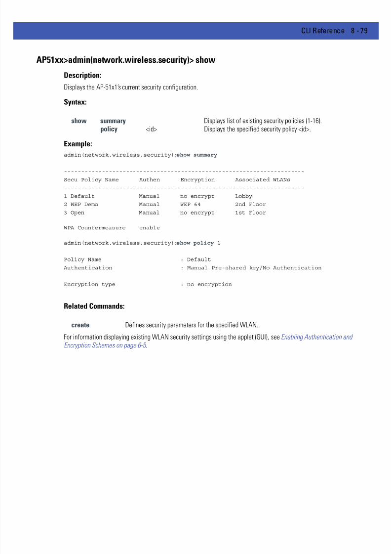
7/18/2019 Motorola AP 5131 Manual
http://slidepdf.com/reader/full/motorola-ap-5131-manual 349/613
CLI Reference 8 - 79
AP51xx>admin(network.wireless.security)> show
Description:
Displays the AP-51x1’s current security configuration.
Syntax:
Example:
admin(network.wireless.security)>show summary
----------------------------------------------------------------------
Secu Policy Name Authen Encryption Associated WLANs
----------------------------------------------------------------------
1 Default Manual no encrypt Lobby
2 WEP Demo Manual WEP 64 2nd Floor
3 Open Manual no encrypt 1st Floor
WPA Countermeasure enable
admin(network.wireless.security)>show policy 1
Policy Name : Default
Authentication : Manual Pre-shared key/No Authentication
Encryption type : no encryption
Related Commands:
For information displaying existing WLAN security settings using the applet (GUI), see Enabling Authentication andEncryption Schemes on page 6-5 .
show summary Displays list of existing security policies (1-16).policy <id> Displays the specified security policy <id>.
create Defines security parameters for the specified WLAN.

7/18/2019 Motorola AP 5131 Manual
http://slidepdf.com/reader/full/motorola-ap-5131-manual 350/613
8 - 80 WiNG 4.4 AP-5131 Product Reference Guide
AP51xx>admin(network.wireless.security)> create
Description:
Defines the parameter of AP-51x1 security policies.
Syntax:
create Defines the parameters of a securitypolicy.
show Displays new or existing security policyparameters.
set sec-name
<name> Sets the name of the security policy.
auth <authtype> Sets the authentication type for WLAN<idx> to <type> (none, eap, or kerberos).
Note: Kerberos parameters are only inaffect if "kerberos" is specified for theauthentication method (set auth <type>).
kerb realm <name> Sets the Kerberos realm.
server <sidx> <ip> Sets the Kerberos server <sidx> (1-primary, 2-backup, or 3-remote) to KDC IPaddress.
port <sidx> <port> Sets the Kerberos port to <port> (KDCport) for server <ksidx> (1-primary, 2-backup, or 3-remote).
Note: EAP parameters are only in affect if"eap" is specified for the authenticationmethod (set auth <type>).
eap server <sidx> <ip> Sets the radius server (1-primary or as 2-secondary) IP address <ip>.
port <sidx> <port> Sets the radius server <sidx> (1-primary or2-secondary) <port> (1-65535).
secret <sidx> <secret> Sets the EAP shared secret <secret> (1-63 characters) for server <sidx> (1-primary or2-secondary).
The default password is now “motorola”instead of “symbol.” Be cognizant of thiswhen importing a configuration from 1.1to 2.1, as this shared secret will have to bechanged to motorola (after the import) toavoid MU authentication failures. Thischange can only be made using the accesspoint CLI.
reauth mode <mode> Enables or disables EAP reauthentication.
period <time> Sets the reauthentication period <period>in seconds (30-9999).
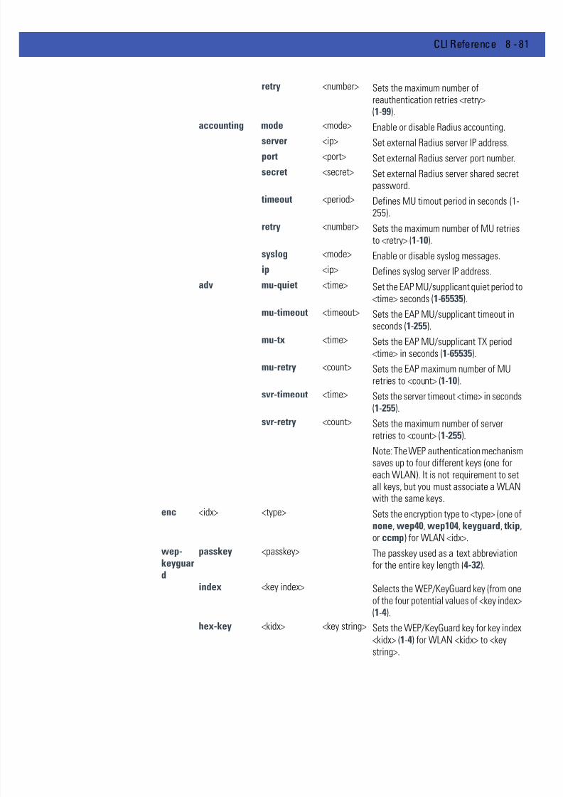
7/18/2019 Motorola AP 5131 Manual
http://slidepdf.com/reader/full/motorola-ap-5131-manual 351/613
CLI Reference 8 - 81
retry <number> Sets the maximum number ofreauthentication retries <retry>(1-99).
accounting mode <mode> Enable or disable Radius accounting.
server <ip> Set external Radius server IP address.
port <port> Set external Radius server port number.
secret <secret> Set external Radius server shared secretpassword.
timeout <period> Defines MU timout period in seconds (1-255).
retry <number> Sets the maximum number of MU retriesto <retry> (1-10).
syslog <mode> Enable or disable syslog messages.
ip <ip> Defines syslog server IP address.
adv mu-quiet <time> Set the EAP MU/supplicant quiet period to<time> seconds (1-65535).
mu-timeout <timeout> Sets the EAP MU/supplicant timeout inseconds (1-255).
mu-tx <time> Sets the EAP MU/supplicant TX period<time> in seconds (1-65535).
mu-retry <count> Sets the EAP maximum number of MUretries to <count> (1-10).
svr-timeout <time> Sets the server timeout <time> in seconds(1-255).
svr-retry <count> Sets the maximum number of serverretries to <count> (1-255).
Note: The WEP authentication mechanismsaves up to four different keys (one foreach WLAN). It is not requirement to setall keys, but you must associate a WLANwith the same keys.
enc <idx> <type> Sets the encryption type to <type> (one ofnone, wep40, wep104, keyguard, tkip,or ccmp) for WLAN <idx>.
wep-keyguard
passkey <passkey>The passkey used as a text abbreviationfor the entire key length (4-32).
index <key index> Selects the WEP/KeyGuard key (from oneof the four potential values of <key index>(1-4).
hex-key <kidx> <key string> Sets the WEP/KeyGuard key for key index<kidx> (1-4) for WLAN <kidx> to <keystring>.

7/18/2019 Motorola AP 5131 Manual
http://slidepdf.com/reader/full/motorola-ap-5131-manual 352/613
8 - 82 WiNG 4.4 AP-5131 Product Reference Guide
For information on configuring the encryption and authentication options available to the access point using the applet(GUI), see Configuring Security Options on page 6-2 .
ascii-key <kidx> <key string> Sets the WEP/KeyGuard key for key index<kidx> (1-4) for WLAN <kidx> to <keystring>.
mixed-mode <mode> Enables or disables interoperation with
WEP128 clients.Note: TKIP parameters are only affected if"tkip" is selected as the encryption type.
tkip rotate-mode <mode> Enables or disabled the broadcast key.
interval <time> Sets the broadcast key rotation interval to<time> in seconds (300-604800).
allow-wpa2- tkip
<mode> Enables or disables the interoperationwith wpa2-tkip clients.
preauth <mode> Enables or disables preauthentication(fast roaming).
type <key type> Sets the TKIP key type.key <256 bit key> Sets the TKIP key to <256 bit key>.
phrase <ascii phrase> Sets the TKIP ASCII pass phrase to <asciiphrase> (8-63 characters).
ccmp rotate-mode <mode> Enables or disabled the broadcast key.
interval <time> Sets the broadcast key rotation interval to<time> in seconds (300-604800).
type <key type> Sets the CCMP key type.
phrase <ascii phrase> Sets the CCMP ASCII pass phrase to<ascii phrase> (8-63 characters).
key <256 bit key> Sets the CCMP key to <256 bit key>.
mixed-mode <mode> Enables or disables mixed mode (allowingWPA-TKIP clients).
preauth <mode> Enables or disables preauthentication(fast roaming).
add-policy
Adds the policy and exits.
.. Disregards the policy creation and exitsthe CLI session.
CAUTION If importing a 1.1 baseline configuration, the 802.1x EAP Radius shared secret password will remain“symbol,” instead of “motorola” (as now required with the 2.0 or later baseline).If the shared secret password is not changed to “motorola” there will be a shared secret mis-matchresulting in MU authentication failures. This password cannot be set using the access point Web UI,and must be changed using the CLI.
!
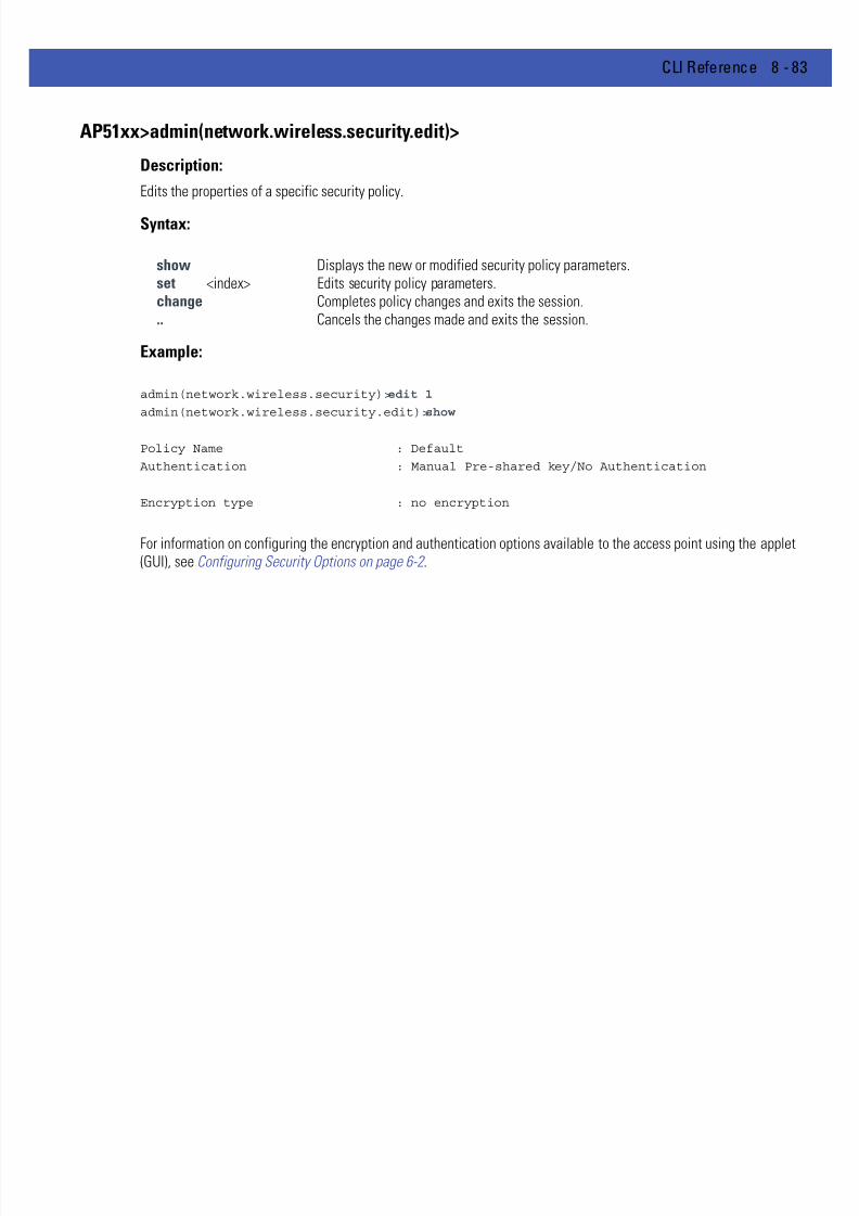
7/18/2019 Motorola AP 5131 Manual
http://slidepdf.com/reader/full/motorola-ap-5131-manual 353/613
CLI Reference 8 - 83
AP51xx>admin(network.wireless.security.edit)>
Description:
Edits the properties of a specific security policy.
Syntax:
Example:
admin(network.wireless.security)>edit 1
admin(network.wireless.security.edit)>show
Policy Name : Default
Authentication : Manual Pre-shared key/No Authentication
Encryption type : no encryption
For information on configuring the encryption and authentication options available to the access point using the applet(GUI), see Configuring Security Options on page 6-2 .
show Displays the new or modified security policy parameters.set <index> Edits security policy parameters.change Completes policy changes and exits the session... Cancels the changes made and exits the session.

7/18/2019 Motorola AP 5131 Manual
http://slidepdf.com/reader/full/motorola-ap-5131-manual 354/613
8 - 84 WiNG 4.4 AP-5131 Product Reference Guide
AP51xx>admin(network.wireless.security)> delete
Description:
Deletes a specific security policy.
Syntax:
For information on configuring the encryption and authentication options available to the access point using the applet(GUI), see Configuring Security Options on page 6-2 .
delete <sec-name> Removes the specified security policy from the list of supported policies.<all> Removes all security policies except the default policy.

7/18/2019 Motorola AP 5131 Manual
http://slidepdf.com/reader/full/motorola-ap-5131-manual 355/613
CLI Reference 8 - 85
8.3.3.3 Network ACL Commands
AP51xx>admin(network.wireless.acl)>
Description:Displays the AP-51x1 Mobile Unit Access Control List (ACL) submenu. The items available under this command include:
show Displays the AP-51x1’s current ACL configuration.create Creates an MU ACL policy.edit Edits the properties of an existing MU ACL policy.delete Removes an MU ACL policy... Goes to the parent menu.
/ Goes to the root menu.save Saves the configuration to system flash.quit Quits the CLI.

7/18/2019 Motorola AP 5131 Manual
http://slidepdf.com/reader/full/motorola-ap-5131-manual 356/613
8 - 86 WiNG 4.4 AP-5131 Product Reference Guide
AP51xx>admin(network.wireless.acl)> show
Description:
Displays the AP-51x1’s current ACL configuration.
Syntax:
Example:
admin(network.wireless.acl)>show summary
----------------------------------------------------------------------
ACL Policy Name Associated WLANs
----------------------------------------------------------------------
1 Default Front Lobby, WLAN1
2 Admin Administration
3 Demo Room Customers
admin(network.wireless.acl)>show policy 1
Policy Name : Default
Policy Mode : allow
-----------------------------------------------------------------------------
index start mac end mac
-----------------------------------------------------------------------------
1 00A0F8348787 00A0F8348798
For information on configuring the ACL options available to the access point using the applet (GUI), see Configuring aWLAN Access Control List (ACL) on page 5-27 .
show summary Displays the list of existing MU ACL policies.policy <index> Displays the requested MU ACL index policy.
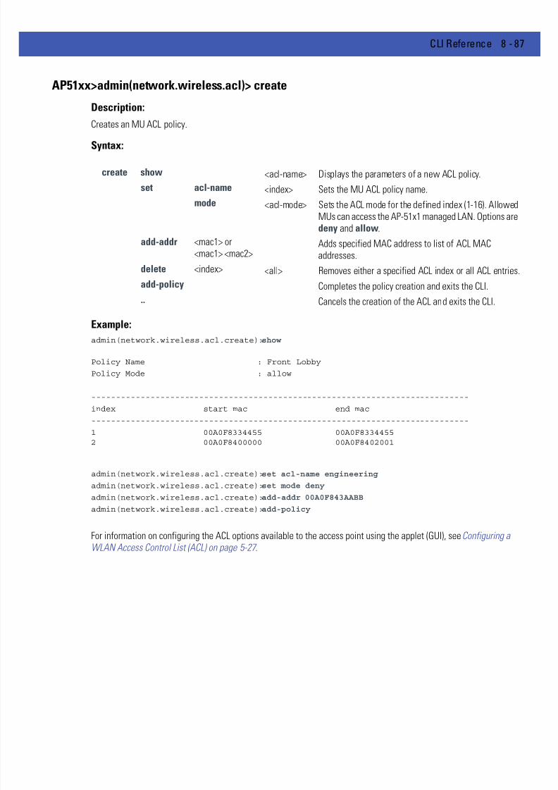
7/18/2019 Motorola AP 5131 Manual
http://slidepdf.com/reader/full/motorola-ap-5131-manual 357/613
CLI Reference 8 - 87
AP51xx>admin(network.wireless.acl)> create
Description:
Creates an MU ACL policy.
Syntax:
Example:
admin(network.wireless.acl.create)>show
Policy Name : Front Lobby
Policy Mode : allow
-----------------------------------------------------------------------------
index start mac end mac
-----------------------------------------------------------------------------
1 00A0F8334455 00A0F83344552 00A0F8400000 00A0F8402001
admin(network.wireless.acl.create)>set acl-name engineering
admin(network.wireless.acl.create)>set mode deny
admin(network.wireless.acl.create)>add-addr 00A0F843AABB
admin(network.wireless.acl.create)>add-policy
For information on configuring the ACL options available to the access point using the applet (GUI), see Configuring a
WLAN Access Control List (ACL) on page 5-27 .
create show <acl-name> Displays the parameters of a new ACL policy.
set acl-name <index> Sets the MU ACL policy name.
mode <acl-mode> Sets the ACL mode for the defined index (1-16). AllowedMUs can access the AP-51x1 managed LAN. Options are deny and allow.
add-addr <mac1> or<mac1> <mac2>
Adds specified MAC address to list of ACL MACaddresses.
delete <index> <all> Removes either a specified ACL index or all ACL entries.
add-policy Completes the policy creation and exits the CLI.
.. Cancels the creation of the ACL and exits the CLI.

7/18/2019 Motorola AP 5131 Manual
http://slidepdf.com/reader/full/motorola-ap-5131-manual 358/613
8 - 88 WiNG 4.4 AP-5131 Product Reference Guide
AP51xx>admin(network.wireless.acl.edit)>
Description:
Edits the properties of an existing MU ACL policy.
Syntax:
For information on configuring the ACL options available to the access point using the applet (GUI), see Configuring a
WLAN Access Control List (ACL) on page 5-27 .
show Displays MU ACL policy and its parameters.set Modifies the properties of an existing MU ACL policy.add-addr Adds an MU ACL table entry.delete Deletes an MU ACL table entry, including starting and ending MAC address ranges.change Completes the changes made and exits the session... Cancels the changes made and exits the session.

7/18/2019 Motorola AP 5131 Manual
http://slidepdf.com/reader/full/motorola-ap-5131-manual 359/613
CLI Reference 8 - 89
AP51xx>admin(network.wireless.acl)> delete
Description:
Removes an MU ACL policy.
Syntax:
For information on configuring the ACL options available to the access point using the applet (GUI), see Configuring aWLAN Access Control List (ACL) on page 5-27 .
delete <acl name> Deletes a partilcular MU ACL policy.all Deletes all MU ACL policies.

7/18/2019 Motorola AP 5131 Manual
http://slidepdf.com/reader/full/motorola-ap-5131-manual 360/613
8 - 90 WiNG 4.4 AP-5131 Product Reference Guide
8.3.3.4 Network Radio Configuration Commands
AP51xx>admin(network.wireless.radio)>
Description:Displays the AP-51x1 Radio submenu. The items available under this command include:
show Summarizes AP-51x1 radio parameters at a high-level.set Defines the access point radio configuration.radio1 Displays the 802.11b/g radio submenu.radio2 Displays the 802.11a radio submenu... Goes to the parent menu.
/ Goes to the root menu.save Saves the configuration to system flash.quit Quits the CLI.
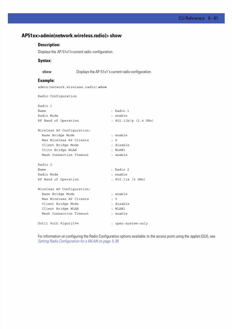
7/18/2019 Motorola AP 5131 Manual
http://slidepdf.com/reader/full/motorola-ap-5131-manual 361/613
CLI Reference 8 - 91
AP51xx>admin(network.wireless.radio)> show
Description:
Displays the AP-51x1’s current radio configuration.
Syntax:
Example:
admin(network.wireless.radio)>show
Radio Configuration
Radio 1
Name : Radio 1
Radio Mode : enableRF Band of Operation : 802.11b/g (2.4 GHz)
Wireless AP Configuration:
Base Bridge Mode : enable
Max Wireless AP Clients : 6
Client Bridge Mode : disable
Clitn Bridge WLAN : WLAN1
Mesh Connection Timeout : enable
Radio 2
Name : Radio 2
Radio Mode : enable
RF Band of Operation : 802.11a (5 GHz)
Wireless AP Configuration:
Base Bridge Mode : enable
Max Wireless AP Clients : 5
Client Bridge Mode : disable
Client Bridge WLAN : WLAN1
Mesh Connection Timeout : enable
Dot11 Auth Algorithm : open-system-only
For information on configuring the Radio Configuration options available to the access point using the applet (GUI), seeSetting Radio Configuration for a WLAN on page 5-38 .
show Displays the AP-51x1’s current radio configuration.
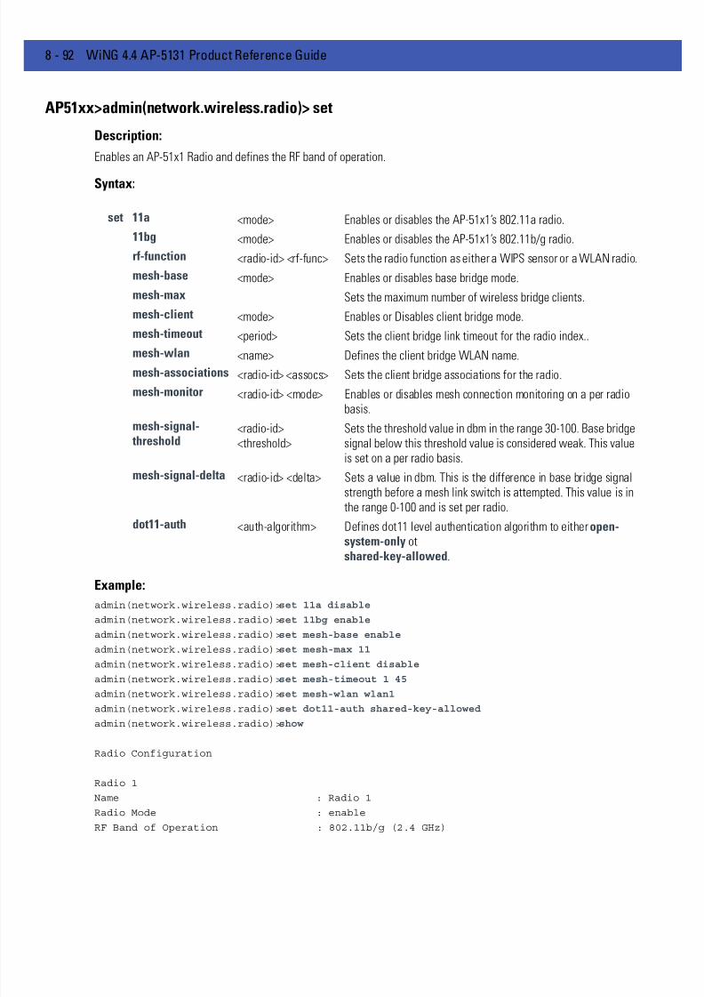
7/18/2019 Motorola AP 5131 Manual
http://slidepdf.com/reader/full/motorola-ap-5131-manual 362/613
8 - 92 WiNG 4.4 AP-5131 Product Reference Guide
AP51xx>admin(network.wireless.radio)> set
Description:
Enables an AP-51x1 Radio and defines the RF band of operation.
Syntax:
Example:
admin(network.wireless.radio)>set 11a disable
admin(network.wireless.radio)>set 11bg enable
admin(network.wireless.radio)>set mesh-base enable
admin(network.wireless.radio)>set mesh-max 11
admin(network.wireless.radio)>set mesh-client disable
admin(network.wireless.radio)>set mesh-timeout 1 45
admin(network.wireless.radio)>set mesh-wlan wlan1admin(network.wireless.radio)>set dot11-auth shared-key-allowed
admin(network.wireless.radio)>show
Radio Configuration
Radio 1
Name : Radio 1
Radio Mode : enable
RF Band of Operation : 802.11b/g (2.4 GHz)
set 11a <mode> Enables or disables the AP-51x1’s 802.11a radio.
11bg <mode> Enables or disables the AP-51x1’s 802.11b/g radio.
rf-function <radio-id> <rf-func> Sets the radio function as either a WIPS sensor or a WLAN radio.
mesh-base <mode> Enables or disables base bridge mode.
mesh-max Sets the maximum number of wireless bridge clients.
mesh-client <mode> Enables or Disables client bridge mode.
mesh-timeout <period> Sets the client bridge link timeout for the radio index..
mesh-wlan <name> Defines the client bridge WLAN name.
mesh-associations <radio-id> <assocs> Sets the client bridge associations for the radio.
mesh-monitor <radio-id> <mode> Enables or disables mesh connection monitoring on a per radiobasis.
mesh-signal- threshold
<radio-id><threshold>
Sets the threshold value in dbm in the range 30-100. Base bridgesignal below this threshold value is considered weak. This valueis set on a per radio basis.
mesh-signal-delta <radio-id> <delta> Sets a value in dbm. This is the difference in base bridge signalstrength before a mesh link switch is attempted. This value is inthe range 0-100 and is set per radio.
dot11-auth <auth-algorithm> Defines dot11 level authentication algorithm to either open-system-only otshared-key-allowed.

7/18/2019 Motorola AP 5131 Manual
http://slidepdf.com/reader/full/motorola-ap-5131-manual 363/613
CLI Reference 8 - 93
Wireless AP Configuration:
Base Bridge Mode : enable
Max Wireless AP Clients : 11
Client Bridge Mode : disable
Clitn Bridge WLAN : WLAN1
Mesh Connection Timeout : 45 sec.
Dot11 Auth Algorithm : shared-key-allowed
For information on configuring the Radio Configuration options available to the access point using the applet (GUI), seeSetting Radio Configuration for a WLAN on page 5-38 .

7/18/2019 Motorola AP 5131 Manual
http://slidepdf.com/reader/full/motorola-ap-5131-manual 364/613
8 - 94 WiNG 4.4 AP-5131 Product Reference Guide
AP51xx>admin(network.wireless.radio.radio1)>
Description:
Displays a specific 802.11b/g radio submenu. The items available under this command include:
Syntax:
For information on configuring Radio 1 Configuration options available to the access point using the applet (GUI), seeSetting Radio Configuration for a WLAN on page 5-38 .
show Displays 802.11b/g radio settings.set Defines specific 802.11b/g radio parameters.advanced Displays the Adavanced radio settings submenu.mesh Goes to the Wireless AP Connections submenu... Goes to the parent menu.
/ Goes to the root menu.save Saves the configuration to system flash.quit Quits the CLI.

7/18/2019 Motorola AP 5131 Manual
http://slidepdf.com/reader/full/motorola-ap-5131-manual 365/613
CLI Reference 8 - 95
AP51xx>admin(network.wireless.radio.radio1)> show
Description:
Displays specific 802.11b/g radio settings.
Syntax:
Example:
admin(network.wireless.radio.radio1)>show radio
Radio Setting Information
Placement : indoor
MAC Address : 00A0F8715920
Radio Type : 802.11b/g
ERP Protection : Off
Channel Setting : user selection
Antenna Diversity : full
Power Level : 5 dbm (4 mW)
802.11b/g mode : B-Only
Basic Rates : 1 2 5.5 11
Supported Rates : 1 2 5.5 11
Beacon Interval : 100 K-usec
DTIM Interval per BSSID
1 : 10 beacon intvls
2 : 10 beacon intvls
3 : 10 beacon intvls
4 : 10 beacon intvls
short preamble : disable
RTS Threshold : 2341 bytes
Extended Range : 0 miles
QBSS Channel Util Beacon Intervl : 10 beacon intvlsQBSS Load Element Mode : enable
show radio Displays specific 802.11b/g radio settings.qos Displays specific 802.11b/g radio WMM QoS settings.

7/18/2019 Motorola AP 5131 Manual
http://slidepdf.com/reader/full/motorola-ap-5131-manual 366/613
8 - 96 WiNG 4.4 AP-5131 Product Reference Guide
admin(network.wireless.radio.radio1)>show qos
Radio QOS Parameter Set 11g-default
-----------------------------------------------------------------------------
Access Category CWMin CWMax AIFSN TXOPs (32 usec) TXOPs ms
-----------------------------------------------------------------------------
Background 15 1023 7 0 0.000
Best Effort 15 63 3 31 0.992
Video 7 15 1 94 3.008
Voice 3 7 1 47 1.504
For information on configuring the Radio 1 Configuration options available to the access point using the applet (GUI), seeConfiguring a WLAN Access Control List (ACL) on page 5-27 .
CAUTION If you do NOT include the index number (for example, "set dtim 50"), the DTIMs for all four BSSIDs willbe changed to 50. To change individual DTIMs for BSSIDs, specify the BSS Index number (for example,"set dtim 2 50). This will change the DTIM for BSSID 2 to 50.!

7/18/2019 Motorola AP 5131 Manual
http://slidepdf.com/reader/full/motorola-ap-5131-manual 367/613
CLI Reference 8 - 97
AP51xx>admin(network.wireless.radio.802-11bg)> set
Description:
Defines specific 802.11b/g radio parameters.
Syntax:
Example:admin(network.wireless.radio.802-11bg)>set placement indoor
admin(network.wireless.radio.802-11bg)>set ch-mode user
admin(network.wireless.radio.802-11bg)>set channel 1
admin(network.wireless.radio.802-11bg)>set antenna full
admin(network.wireless.radio.802-11bg)>set power 4
admin(network.wireless.radio.802-11bg)>set bg-mode enable
admin(network.wireless.radio.802-11bg)>set rates
admin(network.wireless.radio.802-11bg)>set beacon 100
admin(network.wireless.radio.802-11bg)>set dtim 1 40
admin(network.wireless.radio.802-11bg)>set preamble disable
admin(network.wireless.radio.802-11bg)>set rts 2341
admin(network.wireless.radio.802-11bg)>set qos cwmin 125
admin(network.wireless.radio.802-11bg)>set qos cwmax 255admin(network.wireless.radio.802-11bg)>set qos aifsn 7
admin(network.wireless.radio.802-11bg)>set qos txops 0
admin(network.wireless.radio.802-11bg)>set qbss-beacon 110
admin(network.wireless.radio.802-11bg)>set qbss-mode enable
For information on configuring the Radio 1 Configuration options available to the access point using the applet (GUI), seeConfiguring the 802.11a or 802.11b/g Radio on page 5-42 .
set placement Defines the AP-51x1 radio placement as indoors or outdoors.
ch-mode Determines how the radio channel is selected.
channel Defines the actual channel used by the radio.
antenna Sets the radio antenna power
power Defines the radio antenna power transmit level.
bg-mode Enables or disables 802-11bg radio mode support.
rates Sets the supported radio transmit rates.
beacon Sets the beacon interval used by the radio.
dtim Defines the DTIM interval (by index) used by the radio.
preamble Enables or disables support for short preamble for the radio.
rts Defines the RTS Threshold value for the radio.
range Sets the radio’s extended range (in miles 0-50).
qos Defines the cwmin, cwmax, aifsn and txops levels for the QoS policy used for the radio.
qbss-beacon Sets the QBSS Channel Util Beacon Interval in kilo-usec (10 - 200).
qbss-mode Enables/disables the QBSS load element.
CAUTION If you do NOT include the index number (for example, "set dtim 50"), the DTIMs for all four BSSIDs willbe changed to 50. To change individual DTIMs for BSSIDs, specify the BSS Index number (for example,"set dtim 2 50). This will change the DTIM for BSSID 2 to 50.!

7/18/2019 Motorola AP 5131 Manual
http://slidepdf.com/reader/full/motorola-ap-5131-manual 368/613
8 - 98 WiNG 4.4 AP-5131 Product Reference Guide
AP51xx>admin(network.wireless.radio.802-11bg.advanced)>
Description:
Displays the advanced submenu for the 802.11b/g radio. The items available under this command include:
Syntax:
show Displays advanced radio settings for the 802.11b/g radio.set Defines advanced parameters for the 802.11b/g radio... Goes to the parent menu.
/ Goes to the root menu.save Saves the configuration to system flash.quit Quits the CLI.

7/18/2019 Motorola AP 5131 Manual
http://slidepdf.com/reader/full/motorola-ap-5131-manual 369/613
CLI Reference 8 - 99
AP51xx>admin(network.wireless.radio.802-11bg.advanced)> show
Description:
Displays the BSSID to WLAN mapping for the 802.11b/g radio.
Syntax:
Example:
admin(network.wireless.radio.802-11bg.advanced)>show advanced
-----------------------------------------------------------------------------
WLAN BSS ID BC/MC Cipher Status Message
-----------------------------------------------------------------------------
Lobby 1 Open good configuration is ok
HR 2 Open good configuration is ok
Office 3 Open good configuration is ok
-----------------------------------------------------------------------------
BSSID Primary WLAN
-----------------------------------------------------------------------------
1 Lobby
2 HR
3 Office
admin(network.wireless.radio.802-11bg.advanced)>show wlan
WLAN 1:
WLAN name : WLAN1
ESS ID : 101
Radio : 11a,11b/g
VLAN : <none>
Security Policy : Default
QoS Policy : Default
For information on configuring Radio 1 Configuration options available to the access point using the applet (GUI), seeConfiguring the 802.11a or 802.11b/g Radio on page 5-42 .
show advanced Displays advanced settings for the 802.11b/g radio.wlan Displays WLAN summary list for the 802.11b/g radio.

7/18/2019 Motorola AP 5131 Manual
http://slidepdf.com/reader/full/motorola-ap-5131-manual 370/613
8 - 100 WiNG 4.4 AP-5131 Product Reference Guide
AP51xx>admin(network.wireless.radio.802-11bg.advanced)> set
Description:
Defines advanced parameters for the target 802.11b/g radio.
Syntax:
Example:
admin(network.wireless.radio.802-11bg.advanced)>set wlan demoroom 1
admin(network.wireless.radio.802-11bg.advanced)>set bss 1 demoroom
For information on configuring Radio 1 Configuration options available to the access point using the applet (GUI), see
Configuring the 802.11a or 802.11b/g Radio on page 5-42 .
set wlan <wlan-name> <bssid> Defines advanced WLAN to BSSID mapping for the target radio.
bss <bss-id> <wlan name> Sets the BSSID to primary WLAN definition.
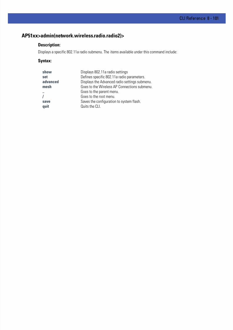
7/18/2019 Motorola AP 5131 Manual
http://slidepdf.com/reader/full/motorola-ap-5131-manual 371/613
CLI Reference 8 - 101
AP51xx>admin(network.wireless.radio.radio2)>
Description:
Displays a specific 802.11a radio submenu. The items available under this command include:
Syntax:
show Displays 802.11a radio settingsset Defines specific 802.11a radio parameters.advanced Displays the Advanced radio settings submenu.mesh Goes to the Wireless AP Connections submenu... Goes to the parent menu.
/ Goes to the root menu.save Saves the configuration to system flash.quit Quits the CLI.

7/18/2019 Motorola AP 5131 Manual
http://slidepdf.com/reader/full/motorola-ap-5131-manual 372/613
8 - 102 WiNG 4.4 AP-5131 Product Reference Guide
AP51xx>admin(network.wireless.radio.802-11a)> show
Description:
Displays specific 802.11a radio settings.
Syntax:
Example:
admin(network.wireless.radio.802-11a)>show radio
Radio Setting Information
Placement : indoor
MAC Address : 00A0F8715920
Radio Type : 802.11a
Channel Setting : user selection
Antenna Diversity : full
Power Level : 5 dbm (4 mW)
Basic Rates : 6 12 24
Supported Rates : 6 9 12 18 24 36 48 54
Beacon Interval : 100 K-usec
DTIM Interval per BSSID
1 : 10 beacon intvls
2 : 10 beacon intvls
3 : 10 beacon intvls
4 : 10 beacon intvls
RTS Threshold : 2341 bytes
Extended Range : 0 miles
QBSS Channel Util Beacon Intervl : 10 beacon intvls
QBSS Load Element Mode : enable
admin(network.wireless.radio.802-11a)>show qos
Radio QOS Parameter Set: 11a default
-----------------------------------------------------------------------------
Access Category CWMin CWMax AIFSN TXOPs (32 sec) TXOPs ms
-----------------------------------------------------------------------------
Background 15 1023 7 0 0.000
Best Effort 15 63 3 31 0.992
Video 7 15 1 94 3.008
Voice 3 7 1 47 1.504
For information on configuring Radio 2 Configuration options available to the access point using the applet (GUI), seeConfiguring the 802.11a or 802.11b/g Radio on page 5-42 .
show radio Displays specific 802.11a radio settings.qos Displays specific 802.11a radio WMM QoS settings.

7/18/2019 Motorola AP 5131 Manual
http://slidepdf.com/reader/full/motorola-ap-5131-manual 373/613
CLI Reference 8 - 103
AP51xx>admin(network.wireless.radio.802-11a)> set
Description:
Defines specific 802.11a radio parameters.
Syntax:
Example:
admin(network.wireless.radio.802-11a)>
admin(network.wireless.radio.802-11a)>set placement indoor
admin(network.wireless.radio.802-11a)>set ch-mode user
admin(network.wireless.radio.802-11a)>set channel 1
admin(network.wireless.radio.802-11a)>set antenna full
admin(network.wireless.radio.802-11a)>set power 4
admin(network.wireless.radio.802-11a)>set rates
admin(network.wireless.radio.802-11a)>set beacon 100
admin(network.wireless.radio.802-11a)>set dtim 1 10
admin(network.wireless.radio.802-11a)>set rts 2341
admin(network.wireless.radio.802-11a)>set qos cwmin 125
admin(network.wireless.radio.802-11a)>set qos cwmax 255
admin(network.wireless.radio.802-11a)>set qos aifsn 7admin(network.wireless.radio.802-11a)>set qos txops 0
admin(network.wireless.radio.802-11a)>set qbss-beacon 110
admin(network.wireless.radio.802-11a)>set qbss-mode enable
For information on configuring the Radio 2 Configuration options available to the access point using the applet (GUI), seeConfiguring the 802.11a or 802.11b/g Radio on page 5-42 .
set placement Defines the AP-51x1 radio placement as indoors or outdoors.
ch-mode Determines how the radio channel is selected.
channel Defines the actual channel used by the radio.
antenna Sets the radio antenna power.
power Defines the radio antenna power transmit level.
rates Sets the supported radio transmit rates.
beacon Sets the beacon interval used by the radio.
dtim Defines the DTIM interval (by index) used by the radio.
rts Defines the RTS Threshold value for the radio.
range Sets the radio’s extended range (from 0-50 miles)
qos Defines the cwmin, cwmax, aifsn and txops levels for the QoS policy used for the radio.
qbss-beacon Sets the QBSS Channel Util Beacon Interval in kilo-usec (10 - 200).
qbss-mode Enables/disables the QBSS load element.

7/18/2019 Motorola AP 5131 Manual
http://slidepdf.com/reader/full/motorola-ap-5131-manual 374/613
8 - 104 WiNG 4.4 AP-5131 Product Reference Guide
AP51xx>admin(network.wireless.radio.802-11a.advanced)>
Description:
Displays the advanced submenu for the 802-11a radio. The items available under this command include:
Syntax:
show Displays advanced radio settings for the 802-11a radio.set Defines advanced parameters for the 802-11a radio... Goes to the parent menu.
/ Goes to the root menu.save Saves the configuration to system flash.quit Quits the CLI.

7/18/2019 Motorola AP 5131 Manual
http://slidepdf.com/reader/full/motorola-ap-5131-manual 375/613
CLI Reference 8 - 105
AP51xx>admin(network.wireless.radio.802-11a.advanced)> show
Description:
Displays the BSSID to WLAN mapping for the 802.11a radio.
Syntax:
Example:
admin(network.wireless.radio.802-11a.advanced)>show advanced
-----------------------------------------------------------------------------
WLAN BSS ID BC/MC Cipher Status Message
-----------------------------------------------------------------------------
Lobby 1 Open good configuration is ok
HR 2 Open good configuration is ok
Office 3 Open good configuration is ok
-----------------------------------------------------------------------------
BSSID Primary WLAN
-----------------------------------------------------------------------------
1 Lobby
2 HR
3 Office
admin(network.wireless.radio.802-11bg.advanced)>show wlan
WLAN 1:
WLAN name : WLAN1
ESS ID : 101
Radio : 11a, 11b/g
VLAN : <none>
Security Policy : Default
QoS Policy : Default
For information on configuring the Radio 2 Configuration options available to the access point using the applet (GUI), seeConfiguring the 802.11a or 802.11b/g Radio on page 5-42 .
show advanced Displays advanced settings for the 802.11a radio.wlan Displays WLAN summary list for 802.11a radio.

7/18/2019 Motorola AP 5131 Manual
http://slidepdf.com/reader/full/motorola-ap-5131-manual 376/613
8 - 106 WiNG 4.4 AP-5131 Product Reference Guide
AP51xx>admin(network.wireless.radio.802-11a.advanced)> set
Description:
Defines advanced parameters for the target 802..11a radio.
Syntax:
Example:
admin(network.wireless.radio.802-11a.advanced)>set wlan demoroom 1
admin(network.wireless.radio.802-11a.advanced)>set bss 1 demoroom
For information on configuring Radio 2 Configuration options available to the access point using the applet (GUI), see
Configuring the 802.11a or 802.11b/g Radio on page 5-42 .
set wlan <wlan-name> <bssid> Defines advanced WLAN to BSSID mapping for the target radio.
bss <bss-id> <wlan name> Sets the BSSID to primary WLAN definition.

7/18/2019 Motorola AP 5131 Manual
http://slidepdf.com/reader/full/motorola-ap-5131-manual 377/613
CLI Reference 8 - 107
8.3.3.5 Network Quality of Service (QoS) Commands
AP51xx>admin(network.wireless.qos)>
Description:Displays the AP-51x1 Quality of Service (QoS) submenu. The items available under this command include:
show Displays AP-51x1 QoS policy information.create Defines the parameters of the QoS policy.edit Edits the settings of an existing QoS policy.delete Removes an existing QoS policy... Goes to the parent menu.
/ Goes to the root menu.save Saves the configuration to system flash.quit Quits the CLI.

7/18/2019 Motorola AP 5131 Manual
http://slidepdf.com/reader/full/motorola-ap-5131-manual 378/613
8 - 108 WiNG 4.4 AP-5131 Product Reference Guide
AP51xx>admin(network.wireless.qos)> show
Description:
Displays the AP-51x1’s current QoS policy by summary or individual policy.
Syntax:
Example:
admin(network.wireless.qos)>show summary
----------------------------------------------------------------------
QOS Policy Name Associated WLANs
----------------------------------------------------------------------
1 Default WLAN1, mudskipper
2 IP Phones Audio Dept
3 Video Vidio Dept
admin(network.wireless.qos)>show policy 1
Policy Name IP Phones
Support Legacy Voice Mode disable
Multicast (Mask) Address 1 01005E000000
Multicast (Mask) Address 2 09000E000000
WMM QOS Mode disable
For information on configuring the WLAN QoS options available to the access point using the applet (GUI), see Setting theWLAN Quality of Service (QoS) Policy on page 5-29 .
show summary Displays all exisiting QoS policies that have been defined.policy <index> Displays the configuration for the requested QoS policy.

7/18/2019 Motorola AP 5131 Manual
http://slidepdf.com/reader/full/motorola-ap-5131-manual 379/613
CLI Reference 8 - 109
AP51xx>admin(network.wireless.qos.create)>
Description:
Defines an AP-51x1 QoS policy.
Syntax:
For information on configuring the WLAN QoS options available to the access point using the applet (GUI), see Setting theWLAN Quality of Service (QoS) Policy on page 5-29 .
show Displays QoS policy parameters.
set qos-name <index> Sets the QoS name for the specified index entry.
vop <index> Enables or disables support (by index) for legacy VOIP devices.
mcast <mac> Defines primary and secondary Multicast MAC address.
wmm-qos <index> Enables or disables the QoS policy index specified.
param-set <set-name> Defines the data type used with the qos policy and meshnetwork. When set to a value other then manual, editing the
access category values is not necessary. Options include; 11g-default, 11b-default, 11g-wifi, 11b-wifi, 11g-voice, 11b-voice ormanual for advanced users).
cwmin <accesscategory>
<index> Defines Minimum Contention Window (CW-Min) for specifiedaccess categoiry and index.
cwmax <accesscategory>
<index> Defines Maximum Contention Window (CW-Max) for specifiedaccess categoiry and index.
aifsn <accesscategory>
<index> Sets Arbitrary Inter-Frame Space Number (AIFSN) for specifiedaccess categoiry and index.
txops <accesscategory>
<index> Configures Opportunity to Transmit Time (TXOPs Time) forspecified access categoiry and index.
default <index> Defines CWMIN, CWMAX, AIFSN and TXOPs default values.
add-policy Completes the policy edit and exits the session.
.. Cancels the changes and exits.

7/18/2019 Motorola AP 5131 Manual
http://slidepdf.com/reader/full/motorola-ap-5131-manual 380/613
8 - 110 WiNG 4.4 AP-5131 Product Reference Guide
AP51xx>admin(network.wireless.qos.edit)>
Descripton:
Edits the properties of an existing QoS policy.
Syntax:
For information on configuring the WLAN QoS options available to the access point using the applet (GUI), see Setting theWLAN Quality of Service (QoS) Policy on page 5-29 .
show Displays QoS policy parameters.
set qos-name <index> Sets the QoS name for the specified index entry.
vop <index> Enables or disables support (by index) for legacy VOIP devices.
mcast <mac> Defines primary and secondary Multicast MAC address.
wmm-qos <index> Enables or disables the QoS policy index specified.
param-set <set-name> Defines the data type used with the qos policy and mesh network.When set to a value other then manual, editing the access category
values is not necessary. Options include; 11g-default, 11b-default,11g-wifi, 11b-wifi, 11g-voice, 11b-voice or manual for advancedusers).
cwmin <accesscategory>
<index> Defines Minimum Contention Window (CW-Min) for specifiedaccess categoiry and index.
cwmax <accesscategory>
<index> Defines Maximum Contention Window (CW-Max) for specifiedaccess categoiry and index.
aifsn <accesscategory>
<index> Sets Arbitrary Inter-Frame Space Number (AIFSN) for specifiedaccess categoiry and index.
txops <accesscategory>
<index> Configures Opportunity to Transmit Time (TXOPs Time) for specifiedaccess categoiry and index.
default <index> Defines CWMIN, CWMAX, AIFSN and TXOPs default values.
change Completes the policy edit and exits the session.
.. Cancels the changes and exits.

7/18/2019 Motorola AP 5131 Manual
http://slidepdf.com/reader/full/motorola-ap-5131-manual 381/613
CLI Reference 8 - 111
AP51xx>admin(network.wireless.qos)> delete
Description:
Removes a QoS policy.
Syntax:
For information on configuring the WLAN QoS options available to the access point using the applet (GUI), seeSetting the WLAN Quality of Service (QoS) Policy on page 5-29 .
delete <qos-name> <all> Deletes the specified QoS polciy index, or all of the policies (except default policy).
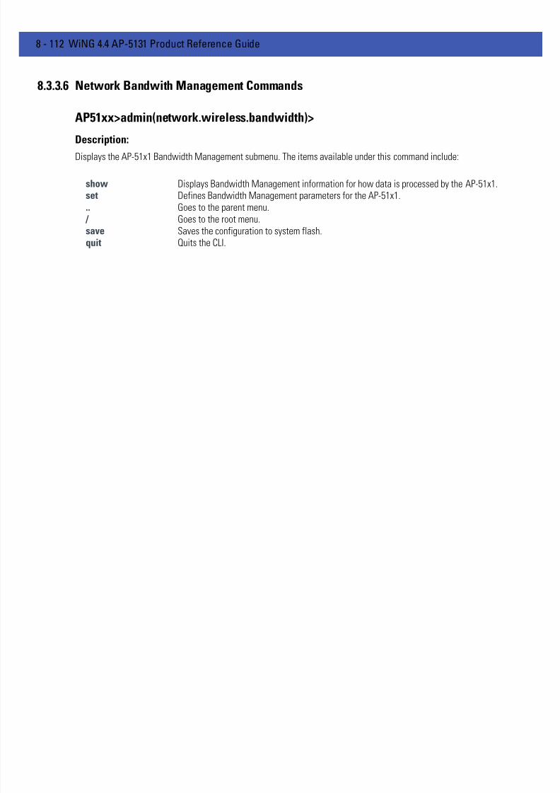
7/18/2019 Motorola AP 5131 Manual
http://slidepdf.com/reader/full/motorola-ap-5131-manual 382/613
8 - 112 WiNG 4.4 AP-5131 Product Reference Guide
8.3.3.6 Network Bandwith Management Commands
AP51xx>admin(network.wireless.bandwidth)>
Description:Displays the AP-51x1 Bandwidth Management submenu. The items available under this command include:
show Displays Bandwidth Management information for how data is processed by the AP-51x1.set Defines Bandwidth Management parameters for the AP-51x1... Goes to the parent menu.
/ Goes to the root menu.save Saves the configuration to system flash.quit Quits the CLI.

7/18/2019 Motorola AP 5131 Manual
http://slidepdf.com/reader/full/motorola-ap-5131-manual 383/613
CLI Reference 8 - 113
AP51xx>admin(network.wireless.bandwidth)> show
Description:
Displays the AP-51x1’s current Bandwidth Management configuration.
Syntax:
Example:
admin(network.wireless.bandwidth)>show
Bandwidth Share Mode : First In First Out
For information on configuring the Bandwidth Management options available to the access point using the applet (GUI),seeConfiguring Bandwidth Management Settings on page 5-48 .
show Displays the current Bandwidth Management configuration for defined WLANs and how they areweighted.

7/18/2019 Motorola AP 5131 Manual
http://slidepdf.com/reader/full/motorola-ap-5131-manual 384/613
8 - 114 WiNG 4.4 AP-5131 Product Reference Guide
AP51xx>admin(network.wireless.bandwidth)> set
Description:
Defines the AP-51x1 Bandwidth Management configuration.
Syntax:
For information on configuring the Bandwidth Management options available to the access point using the applet (GUI),see
Configuring Bandwidth Management Settings on page 5-48 .
set mode <bw-mode> Defines bandwidth share mode of First In First Out <fifo>, Round Robin <rr> orWeighted Round Robin <wrr>
weight <num> Assigns a bandwidth share allocation for the WLAN <index 1-16 > when WeightedRound Robin <wrr> is selected. The weighting is from 1-10.

7/18/2019 Motorola AP 5131 Manual
http://slidepdf.com/reader/full/motorola-ap-5131-manual 385/613
CLI Reference 8 - 115
8.3.3.7 Network Rogue-AP Commands
AP51xx>admin(network.wireless.rogue-ap)>
Description:Displays the Rogue AP submenu. The items available under this command include:
show Displays the current AP-51x1 Rogue AP detection configuration.set Defines the Rogue AP detection method.mu-scan Goes to the Rogue AP mu-uscan submenu.allowed-list Goes to the Rogue AP Allowed List submenu.active-list Goes the Rogue AP Active List submenu.rogue-list Goes the Rogue AP List submenu... Goes to the parent menu.
/ Goes to the root menu.
save Saves the configuration to system flash.quit Quits the CLI.
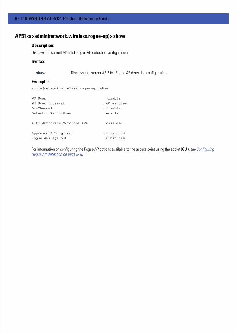
7/18/2019 Motorola AP 5131 Manual
http://slidepdf.com/reader/full/motorola-ap-5131-manual 386/613
8 - 116 WiNG 4.4 AP-5131 Product Reference Guide
AP51xx>admin(network.wireless.rogue-ap)> show
Description:
Displays the current AP-51x1 Rogue AP detection configuration.
Syntax:
Example:
admin(network.wireless.rogue-ap)>show
MU Scan : disable
MU Scan Interval : 60 minutes
On-Channel : disable
Detector Radio Scan : enable
Auto Authorize Motorola APs : disable
Approved APs age out : 0 minutes
Rogue APs age out : 0 minutes
For information on configuring the Rogue AP options available to the access point using the applet (GUI), see ConfiguringRogue AP Detection on page 6-48 .
show Displays the current AP-51x1 Rogue AP detection configuration.
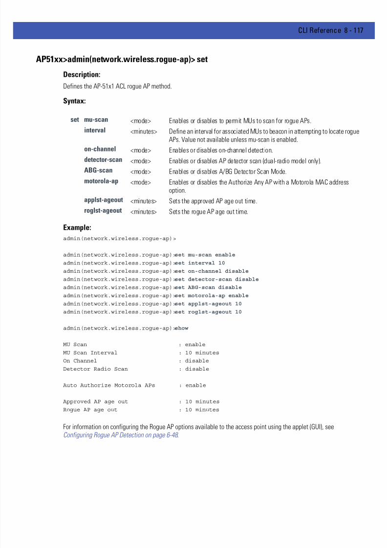
7/18/2019 Motorola AP 5131 Manual
http://slidepdf.com/reader/full/motorola-ap-5131-manual 387/613
CLI Reference 8 - 117
AP51xx>admin(network.wireless.rogue-ap)> set
Description:
Defines the AP-51x1 ACL rogue AP method.
Syntax:
Example:
admin(network.wireless.rogue-ap)>
admin(network.wireless.rogue-ap)>set mu-scan enable
admin(network.wireless.rogue-ap)>set interval 10
admin(network.wireless.rogue-ap)>set on-channel disable
admin(network.wireless.rogue-ap)>set detector-scan disable
admin(network.wireless.rogue-ap)>set ABG-scan disableadmin(network.wireless.rogue-ap)>set motorola-ap enable
admin(network.wireless.rogue-ap)>set applst-ageout 10
admin(network.wireless.rogue-ap)>set roglst-ageout 10
admin(network.wireless.rogue-ap)>show
MU Scan : enable
MU Scan Interval : 10 minutes
On Channel : disable
Detector Radio Scan : disable
Auto Authorize Motorola APs : enable
Approved AP age out : 10 minutes
Rogue AP age out : 10 minutes
For information on configuring the Rogue AP options available to the access point using the applet (GUI), seeConfiguring Rogue AP Detection on page 6-48 .
set mu-scan <mode> Enables or disables to permit MUs to scan for rogue APs.
interval <minutes> Define an interval for associated MUs to beacon in attempting to locate rogueAPs. Value not available unless mu-scan is enabled.
on-channel <mode> Enables or disables on-channel detection.
detector-scan <mode> Enables or disables AP detector scan (dual-radio model only).
ABG-scan <mode> Enables or disables A/BG Detector Scan Mode.
motorola-ap <mode> Enables or disables the Authorize Any AP with a Motorola MAC address
option.applst-ageout <minutes> Sets the approved AP age out time.
roglst-ageout <minutes> Sets the rogue AP age out time.

7/18/2019 Motorola AP 5131 Manual
http://slidepdf.com/reader/full/motorola-ap-5131-manual 388/613
8 - 118 WiNG 4.4 AP-5131 Product Reference Guide
AP51xx>admin(network.wireless.rogue-ap.mu-scan)>
Description:
Displays the Rogue-AP mu-scan submenu.
Syntax:
add Add all or just one scan result to Allowed AP list.show Displays all APs located by the MU scan.start Initiates scan immediately by the MU... Goes to the parent menu.
/ Goes to the root menu.save Saves the configuration to system flash.quit Quits the CLI.

7/18/2019 Motorola AP 5131 Manual
http://slidepdf.com/reader/full/motorola-ap-5131-manual 389/613
CLI Reference 8 - 119
AP51xx>admin(network.wireless.rogue-ap.mu-scan)> start
Description:
Initiates an MU scan from a user provided MAC address.
Syntax:
For information on configuring the Rogue AP options available to the access point using the applet (GUI), seeConfiguring Rogue AP Detection on page 6-48 .
start <mu-mac> Initiates MU scan from user provided MAC address.

7/18/2019 Motorola AP 5131 Manual
http://slidepdf.com/reader/full/motorola-ap-5131-manual 390/613
8 - 120 WiNG 4.4 AP-5131 Product Reference Guide
AP51xx>admin(network.wireless.rogue-ap.mu-scan)> show
Description:
Displays the results of an MU scan.
Syntax:
For information on configuring the Rogue AP options available to the access point using the applet (GUI), seeConfiguring Rogue AP Detection on page 6-48 .
show Displays all APs located by the MU scan.

7/18/2019 Motorola AP 5131 Manual
http://slidepdf.com/reader/full/motorola-ap-5131-manual 391/613
CLI Reference 8 - 121
AP51xx>admin(network.wireless.rogue-ap.allowed-list)>
Description:
Displays the Rogue-AP allowed-list submenu.
show Displays the rogue AP allowed listadd Adds an AP MAC address and ESSID to the allowed list.delete Deletes an entry or all entries from the allowed list... Goes to the parent menu.
/ Goes to the root menu.save Saves the configuration to system flash.quit Quits the CLI.

7/18/2019 Motorola AP 5131 Manual
http://slidepdf.com/reader/full/motorola-ap-5131-manual 392/613
8 - 122 WiNG 4.4 AP-5131 Product Reference Guide
AP51xx>admin(network.wireless.rogue-ap.allowed-list)> show
Description:
Displays the Rogue AP allowed List.
Syntax:
Example:
admin(network.wireless.rogue-ap.allowed-list)>show
Allowed AP List-----------------------------------------------------------------------------
index ap mac essid
-----------------------------------------------------------------------------
1 00:A0:F8:71:59:20 *
2 00:A0:F8:33:44:55 101
3 00:A0:F8:40:20:01 Marketing
For information on configuring the Rogue AP options available to the access point using the applet (GUI), see ConfiguringRogue AP Detection on page 6-48 .
show Displays the rogue-AP allowed list.

7/18/2019 Motorola AP 5131 Manual
http://slidepdf.com/reader/full/motorola-ap-5131-manual 393/613
CLI Reference 8 - 123
AP51xx>admin(network.wireless.rogue-ap.allowed-list)> add
Description:
Adds an AP MAC address and ESSID to existing allowed list.
Syntax:
Example:
admin(network.wireless.rogue-ap.allowed-list)>add 00A0F83161BB 103
admin(network.wireless.rogue-ap.allowed-list)>show
-----------------------------------------------------------------------------
index ap essid
-----------------------------------------------------------------------------
1 00:A0:F8:71:59:20 *
2 00:A0:F8:33:44:55 fffffffffff
3 00:A0:F8:40:20:01 Marketing
4 00:A0:F8:31:61:BB 103
For information on configuring the Rogue AP options available to the access point using the applet (GUI), see ConfiguringRogue AP Detection on page 6-48 .
add <mac-addr> <ess-id> Adds an AP MAC address and ESSID to existing allowed list.“fffffffffffffffff” means any MAC. Use a “*” for any ESSID.

7/18/2019 Motorola AP 5131 Manual
http://slidepdf.com/reader/full/motorola-ap-5131-manual 394/613
8 - 124 WiNG 4.4 AP-5131 Product Reference Guide
AP51xx>admin(network.wireless.rogue-ap.allowed-list)> delete
Description:
Deletes an AP MAC address and ESSID to existing allowed list.
Syntax:
For information on configuring the Rogue AP options available to the access point using the applet (GUI), see ConfiguringRogue AP Detection on page 6-48 .
delete <idx> <all> Deletes an AP MAC address and ESSID (or all addresses) from the allowed list.
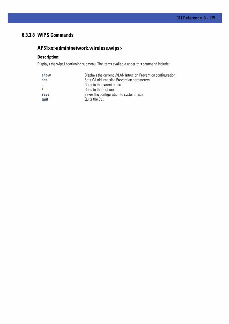
7/18/2019 Motorola AP 5131 Manual
http://slidepdf.com/reader/full/motorola-ap-5131-manual 395/613
CLI Reference 8 - 125
8.3.3.8 WIPS Commands
AP51xx>admin(network.wireless.wips>
Description:Displays the wips Locationing submenu. The items available under this command include:
show Displays the current WLAN Intrusion Prevention configuration.set Sets WLAN Intrusion Prevention parameters... Goes to the parent menu.
/ Goes to the root menu.save Saves the configuration to system flash.quit Quits the CLI.
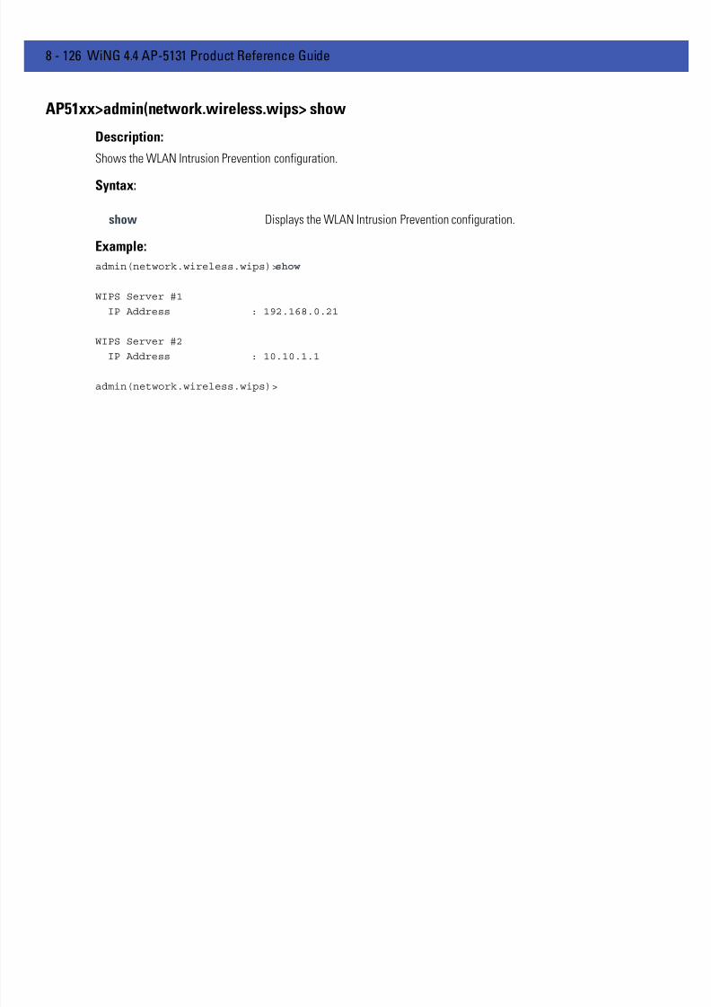
7/18/2019 Motorola AP 5131 Manual
http://slidepdf.com/reader/full/motorola-ap-5131-manual 396/613
8 - 126 WiNG 4.4 AP-5131 Product Reference Guide
AP51xx>admin(network.wireless.wips> show
Description:
Shows the WLAN Intrusion Prevention configuration.
Syntax:
Example:
admin(network.wireless.wips)>show
WIPS Server #1
IP Address : 192.168.0.21
WIPS Server #2
IP Address : 10.10.1.1
admin(network.wireless.wips)>
show Displays the WLAN Intrusion Prevention configuration.

7/18/2019 Motorola AP 5131 Manual
http://slidepdf.com/reader/full/motorola-ap-5131-manual 397/613
CLI Reference 8 - 127
AP51xx>admin(network.wireless.wips> set
Description:
Sets the WLAN Intrusion Prevention configuration.
Syntax:
Example:
admin(network.wireless.wips)>set server 1 192.168.0.21
admin(network.wireless.wips>
set <idx 1 and 2> <ip> Defines the WLAN Intrusion Prevention Server IP Address for (server IPs 1 and 2)

7/18/2019 Motorola AP 5131 Manual
http://slidepdf.com/reader/full/motorola-ap-5131-manual 398/613
8 - 128 WiNG 4.4 AP-5131 Product Reference Guide
8.3.3.9 Network MU Locationing Commands
AP51xx>admin(network.wireless.mu-locationing)>
Description:Displays the MU Locationing submenu. The items available under this command include:
show Displays the current MU Locationing configuration.set Defines MU Locationing parameters... Goes to the parent menu.
/ Goes to the root menu.save Saves the configuration to system flash.quit Quits the CLI.

7/18/2019 Motorola AP 5131 Manual
http://slidepdf.com/reader/full/motorola-ap-5131-manual 399/613
CLI Reference 8 - 129
AP51xx>admin(network.wireless.mu-locationing> show
Description:
Displays the MU probe table configuration
Syntax:
Example:
admin(network.wireless.mu-locationing)>show
MU Probe Table Mode : disable
MU Probe Table Size : 200
admin(network.wireless.mu-locationing)>
show Displays the MU probe table configuration.

7/18/2019 Motorola AP 5131 Manual
http://slidepdf.com/reader/full/motorola-ap-5131-manual 400/613
8 - 130 WiNG 4.4 AP-5131 Product Reference Guide
AP51xx>admin(network.wireless.mu-locationing> set
Description:
Defines the MU probe table configuration used for locating MUs.
Syntax:
Example:
admin(network.wireless.mu-locationing)>set
admin(network.wireless.mu-locationing)>set mode enable
admin(network.wireless.mu-locationing)>set size 200
admin(network.wireless.mu-locationing)>
set Defines the MU probe table configuration.mode Enables/disables a mu probe scan.size Defines the number of MUs in the table (the maximum allowed is 200).

7/18/2019 Motorola AP 5131 Manual
http://slidepdf.com/reader/full/motorola-ap-5131-manual 401/613
CLI Reference 8 - 131
8.3.4 Network Firewall Commands
AP51xx>admin(network.firewall)>
Description:Displays the AP-51x1 firewall submenu. The items available under this command include:
show Displays the AP-51x1’s current firewall configuration.set Defines the AP-51x1’s firewall parameters.access Enables/disables firewall permissions through the LAN and WAN ports.advanced Displays interoperaility rules between the LAN and WAN ports... Goes to the parent menu.
/ Goes to the root menu.save Saves the configuration to system flash.quit Quits the CLI.

7/18/2019 Motorola AP 5131 Manual
http://slidepdf.com/reader/full/motorola-ap-5131-manual 402/613
8 - 132 WiNG 4.4 AP-5131 Product Reference Guide
AP51xx>admin(network.firewall)> show
Description:
Displays the AP-51x1 firewall parameters.
Syntax:
Example:
admin(network.firewall)>show
Firewall Status : disable
NAT Timeout : 10 minutes
Configurable Firewall Filters:
ftp bounce attack filter : enable
syn flood attack filter : enable
unaligned ip timestamp filter : enable
source routing attack filter : enable
winnuke attack filter : enable
seq num prediction attack filter : enable
mime flood attack filter : enable
max mime header length : 8192 bytes
max mime headers : 16 headers
For information on configuring the Firewall options available to the access point using the applet (GUI), see ConfiguringFirewall Settings on page 6-25 .
show Shows all AP-51x1’s firewall settings.
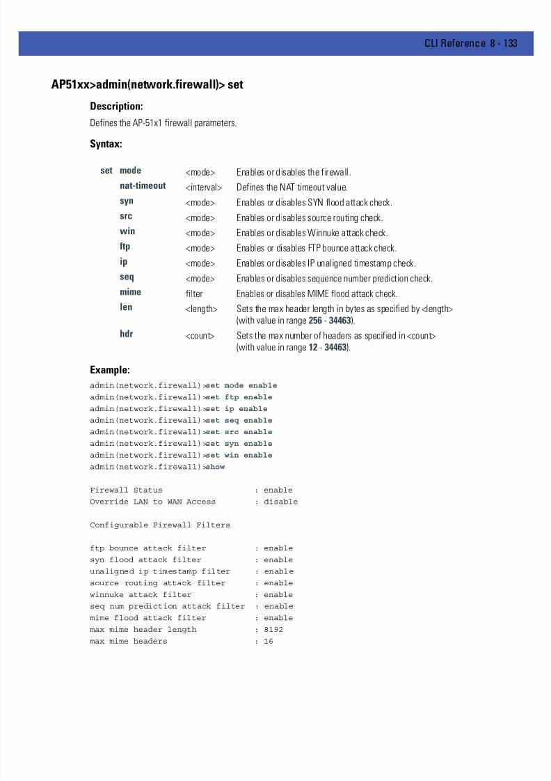
7/18/2019 Motorola AP 5131 Manual
http://slidepdf.com/reader/full/motorola-ap-5131-manual 403/613
CLI Reference 8 - 133
AP51xx>admin(network.firewall)> set
Description:
Defines the AP-51x1 firewall parameters.
Syntax:
Example:
admin(network.firewall)>set mode enable
admin(network.firewall)>set ftp enable
admin(network.firewall)>set ip enableadmin(network.firewall)>set seq enable
admin(network.firewall)>set src enable
admin(network.firewall)>set syn enable
admin(network.firewall)>set win enable
admin(network.firewall)>show
Firewall Status : enable
Override LAN to WAN Access : disable
Configurable Firewall Filters
ftp bounce attack filter : enablesyn flood attack filter : enable
unaligned ip timestamp filter : enable
source routing attack filter : enable
winnuke attack filter : enable
seq num prediction attack filter : enable
mime flood attack filter : enable
max mime header length : 8192
max mime headers : 16
set mode <mode> Enables or disables the firewall.
nat-timeout <interval> Defines the NAT timeout value.
syn <mode> Enables or disables SYN flood attack check.
src <mode> Enables or disables source routing check.
win <mode> Enables or disables Winnuke attack check.
ftp <mode> Enables or disables FTP bounce attack check.
ip <mode> Enables or disables IP unaligned timestamp check.
seq <mode> Enables or disables sequence number prediction check.
mime filter Enables or disables MIME flood attack check.
len <length> Sets the max header length in bytes as specified by <length>(with value in range 256 - 34463).
hdr <count> Sets the max number of headers as specified in <count>(with value in range 12 - 34463).

7/18/2019 Motorola AP 5131 Manual
http://slidepdf.com/reader/full/motorola-ap-5131-manual 404/613
8 - 134 WiNG 4.4 AP-5131 Product Reference Guide
AP51xx>admin(network.firewall)> access
Description:
Enables or disables firewall permissions through LAN to WAN ports.
Syntax:
Example:
admin(network.firewall.lan-wan-access)>list
-----------------------------------------------------------------------------
index from to name prot start port end port
-----------------------------------------------------------------------------
1 lan wan HTTP tcp 80 80
2 lan wan abc udp 0 0
3 lan wan 123456 ah 1440 2048
4 lan wan 654321 tcp 2048 2048
5 lan wan abc ah 100 1000
For information on configuring the Firewall options available to the access point using the applet (GUI), see ConfiguringFirewall Settings on page 6-25 .
show Displays LAN to WAN access rules.set Sets LAN to WAN access rules.add Adds LAN to WAN exception rules.delete Deletes LAN to WAN access exception rules.list Displays LAN to WAN access exception rules... Goes to parent menu
/ Goes to root menu.save Saves configuration to system flash.quit Quits and exits the CLI session.

7/18/2019 Motorola AP 5131 Manual
http://slidepdf.com/reader/full/motorola-ap-5131-manual 405/613
CLI Reference 8 - 135
AP51xx>admin(network.firewall)> advanced
Description:
Displays whether an AP-51x1 firewall rule is intended for inbound traffic to an interface or outbound traffic from that
interface..
Syntax:
Example:
admin(network.firewall.adv-lan-access)>inbound
admin(network.firewall.adv-lan-access.inb)>list
-----------------------------------------------------------------------------
Idx SCR IP-Netmask Dst IP-Netmask TP SPorts DPorts Rev NAT Action
-----------------------------------------------------------------------------
1 1.2.3.4 2.2.2.2 all 1: 1: 0.0.0.0 deny
255.0.0.0 255.0.0.0 65535 65535 nat port 332 33.3.0.0 10.10.1.1 tcp 1: 1: 11.11.1.0 allow
255.255.255.0 255.255.255.0 65535 65535 nat port 0
For information on configuring the Firewall options available to the access point using the applet (GUI), see ConfiguringFirewall Settings on page 6-25 .
show Shows advanced subnet access parameters.set Sets advanced subnet access parameters.import Imports rules from subnet access.inbound Goes to the Inbound Firewall Rules submenu.outbound Goes to the Outbound Firewall Rules submenu... Goes to the parent menu.
/ Goes to the root menu.save Saves the configuration to flash memory.
quit Quits and exits the CLI session.

7/18/2019 Motorola AP 5131 Manual
http://slidepdf.com/reader/full/motorola-ap-5131-manual 406/613
8 - 136 WiNG 4.4 AP-5131 Product Reference Guide
8.3.5 Network Router Commands
AP51xx>admin(network.router)>
Description:Displays the router submenu. The items available under this command are:
show Displays the existing AP-51x1 router configuration.set Sets the RIP parameters.add Adds user-defined routes.delete Deletes user-defined routes.list Lists user-defined routes... Goes to the parent menu.
/ Goes to the root menu.save Saves the configuration to system flash.
quit Quits the CLI.
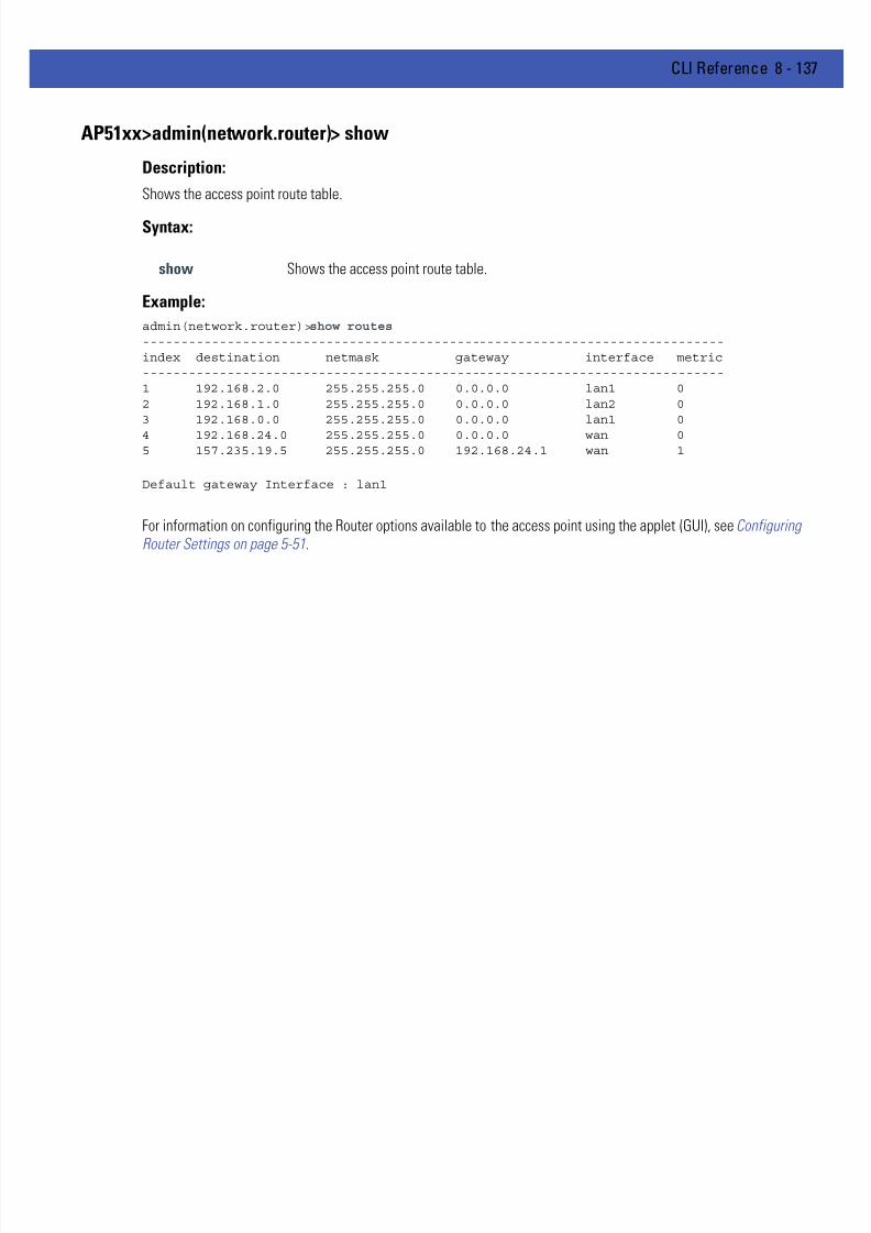
7/18/2019 Motorola AP 5131 Manual
http://slidepdf.com/reader/full/motorola-ap-5131-manual 407/613
CLI Reference 8 - 137
AP51xx>admin(network.router)> show
Description:
Shows the access point route table.
Syntax:
Example:
admin(network.router)>show routes----------------------------------------------------------------------------index destination netmask gateway interface metric----------------------------------------------------------------------------1 192.168.2.0 255.255.255.0 0.0.0.0 lan1 02 192.168.1.0 255.255.255.0 0.0.0.0 lan2 03 192.168.0.0 255.255.255.0 0.0.0.0 lan1 0
4 192.168.24.0 255.255.255.0 0.0.0.0 wan 05 157.235.19.5 255.255.255.0 192.168.24.1 wan 1
Default gateway Interface : lan1
For information on configuring the Router options available to the access point using the applet (GUI), see ConfiguringRouter Settings on page 5-51.
show Shows the access point route table.

7/18/2019 Motorola AP 5131 Manual
http://slidepdf.com/reader/full/motorola-ap-5131-manual 408/613
8 - 138 WiNG 4.4 AP-5131 Product Reference Guide
AP51xx>admin(network.router)> set
Description:
Shows the access point route table.
Syntax:
For information on configuring the Router options available to the access point using the applet (GUI), see ConfiguringRouter Settings on page 5-51.
set auth Sets the RIP authentication type.dir Sets RIP direction.id Sets MD5 authetication ID.key Sets MD5 authetication key.passwd Sets the password for simple authentication.
type Defines the RIP type.dgw-iface Sets the default gateway interface.

7/18/2019 Motorola AP 5131 Manual
http://slidepdf.com/reader/full/motorola-ap-5131-manual 409/613
CLI Reference 8 - 139
AP51xx>admin(network.router)> add
Description:
Adds user-defined routes.
Syntax:
Example:
admin(network.router)>add 192.168.3.0 255.255.255.0 192.168.2.1 LAN1 1
admin(network.router)>list
----------------------------------------------------------------------------index destination netmask gateway interface metric----------------------------------------------------------------------------1 192.168.3.0 255.255.255.0 192.168.2.1 lan1 1
For information on configuring the Router options available to the access point using the applet (GUI), see ConfiguringRouter Settings on page 5-51.
add <dest> <netmask> <gw> <iface> <metric> Adds a route with destination IP address <dest>, IPnetmask <netmask>, destination gateway IP address<gw>, interface LAN1, LAN2 or WAN <iface>, and metricset to <metric> (1-65536).

7/18/2019 Motorola AP 5131 Manual
http://slidepdf.com/reader/full/motorola-ap-5131-manual 410/613
8 - 140 WiNG 4.4 AP-5131 Product Reference Guide
AP51xx>admin(network.router)> delete
Description:
Deletes user-defined routes.
Syntax:
Example:
admin(network.router)>list----------------------------------------------------------------------------index destination netmask gateway interface metric----------------------------------------------------------------------------1 192.168.2.0 255.255.255.0 192.168.0.1 lan1 12 192.168.1.0 255.255.255.0 0.0.0.0 lan2 03 192.168.0.0 255.255.255.0 0.0.0.0 lan2 0
admin(network.router)>delete 2admin(network.router)>list------------------------------------------------------------------index destination netmask gateway interface metric------------------------------------------------------------------1 192.168.2.0 255.255.255.0 0.0.0.0 lan1 02 192.168.0.0 255.255.255.0 0.0.0.0 lan1 0
admin(network.router)>
For information on configuring the Router options available to the access point using the applet (GUI), see Configuring
Router Settings on page 5-51.
delete <idx> Deletes the user-defined route <idx> (1-20) from list.all Deletes all user-defined routes.

7/18/2019 Motorola AP 5131 Manual
http://slidepdf.com/reader/full/motorola-ap-5131-manual 411/613
CLI Reference 8 - 141
AP51xx>admin(network.router)> list
Description:
Lists user-defined routes.
Syntax:
Example:
admin(network.router)>list
----------------------------------------------------------------------------index destination netmask gateway interface metric----------------------------------------------------------------------------1 192.168.2.0 255.255.255.0 192.168.0.1 lan1 12 192.168.1.0 255.255.255.0 0.0.0.0 lan2 03 192.168.0.0 255.255.255.0 0.0.0.0 lan1 0
For information on configuring the Router options available to the access point using the applet (GUI), see ConfiguringRouter Settings on page 5-51.
list Displays a list of user-defined routes.

7/18/2019 Motorola AP 5131 Manual
http://slidepdf.com/reader/full/motorola-ap-5131-manual 412/613
8 - 142 WiNG 4.4 AP-5131 Product Reference Guide
8.4 System Commands
AP51xx>admin(system)>
Description:Displays the System submenu. The items available under this command are shown below.
restart Restarts the AP-51x1.show Shows AP-51x1 system parameter settings.set Defines AP-51x1 system parameter settings.lastpw Displays last debug password.exec Goes to a Linux command menu.arp Dispalys the access point’s arp table.lldp Goes to the LLDP sub menu.aap-setup Goes to the Adaptive AP Settings submenu.
access Goes to the AP-51x1 access submenu where AP-51x1 access methods can be enabled.cmgr Goes the Certificate Manager submenu.snmp Goes to the SNMP submenu.userdb Goes to the user database submenu.radius Goes to the Radius submenu.ntp Goes to the Network Time Protocol submenu.logs Displays the log file submenu.config Goes to the configuration file update submenu.fw-update Goes to the firmware update submenu... Goes to the parent menu.
/ Goes to the root menu.save Saves the configuration to system flash.
quit Quits the CLI.

7/18/2019 Motorola AP 5131 Manual
http://slidepdf.com/reader/full/motorola-ap-5131-manual 413/613
CLI Reference 8 - 143
AP51xx>admin(system)>restart
Description:
Restarts the AP-51x1 access point.
Syntax:
Example:
admin(system)>restart
********************************WARNING***********************************
** Unsaved configuration changes will be lost when the access point is reset.
** Please be sure to save changes before resetting.
**************************************************************************
Are you sure you want to restart the AP-51xx?? (yes/no):
AP-51xx Boot Firmware Version 2.5.1.0-019R
Copyright(c) Motorola 2009. All rights reserved.
Press escape key to run boot firmware ........
Power On Self Test
testing ram : pass
testing nor flash : pass
testing nand flash : pass
testing ethernet : pass
For information on restarting the access point using the applet (GUI), see Configuring System Settings on page 4-3 .
restart Restarts the AP-51x1.

7/18/2019 Motorola AP 5131 Manual
http://slidepdf.com/reader/full/motorola-ap-5131-manual 414/613
8 - 144 WiNG 4.4 AP-5131 Product Reference Guide
AP51xx>admin(system)>show
Description:
Displays high-level system information helpful to differentiate this access point.
Syntax:
Example:
admin(system)>show
system name : BldgC
system location : Atlanta Field Office
admin email address : [email protected]
system uptime : 0 days 4 hours 41 minutes
AP-51xx firmware version : 2.1.0.0-026D
country code : us
ap-mode : independent
serial number : 05224520500336
admin(system)>
For information on displaying System Settings using the applet (GUI), see Configuring System Settings on page 4-3 .
show Displays AP-51x1 system information.

7/18/2019 Motorola AP 5131 Manual
http://slidepdf.com/reader/full/motorola-ap-5131-manual 415/613
CLI Reference 8 - 145
AP51xx>admin(system)>set
Description:
Sets AP-51x1 system parameters.
Syntax:
For information on configuring System Settings using the applet (GUI), see Configuring System Settings on page 4-3 . Referto Appendix A for information on the two-character country codes.
set name <name> Sets the AP-51x1 system name to <name> (1 to 59 characters). The accesspoint does not allow intermediate space characters between characterswithin the system name. For example, “AP51xx sales” must be changed to“AP51xxsales” to be a valid system name.
loc <loc> Sets the AP-51x1 system location to <loc> (1 to 59 characters).
email <email> Sets the AP-51x1 admin email address to <email> (1 to 59 characters).
cc <code> Sets the AP-51x1 country code using two-letters <code>.

7/18/2019 Motorola AP 5131 Manual
http://slidepdf.com/reader/full/motorola-ap-5131-manual 416/613
8 - 146 WiNG 4.4 AP-5131 Product Reference Guide
AP51xx>admin(system)>lastpw
Description:
Displays last expired debug password.
Example:
admin(system)>lastpw
AP-51xx MAC Address is 00:15:70:02:7A:66
Last debug password was motorola
Current debug password used 0 times, valid 4 more time(s)
admin(system)>

7/18/2019 Motorola AP 5131 Manual
http://slidepdf.com/reader/full/motorola-ap-5131-manual 417/613
CLI Reference 8 - 147
AP51xx>admin(system)>arp
Description:
Dispalys the access point’s arp table.
Example:
admin(system)>arp
Address HWtype HWaddress Flags Mask Iface
157.235.92.210 ether 00:11:25:14:61:A8 C ixp1
157.235.92.179 ether 00:14:22:F3:D7:39 C ixp1
157.235.92.248 ether 00:11:25:B2:09:60 C ixp1
157.235.92.180 ether 00:0D:60:D0:06:90 C ixp1
157.235.92.3 ether 00:D0:2B:A0:D4:FC C ixp1
157.235.92.181 ether 00:15:C5:0C:19:27 C ixp1
157.235.92.80 ether 00:11:25:B2:0D:06 C ixp1157.235.92.95 ether 00:14:22:F9:12:AD C ixp1
157.235.92.161 ether 00:06:5B:97:BD:6D C ixp1
157.235.92.126 ether 00:11:25:B2:29:64 C ixp1
admin(system)>
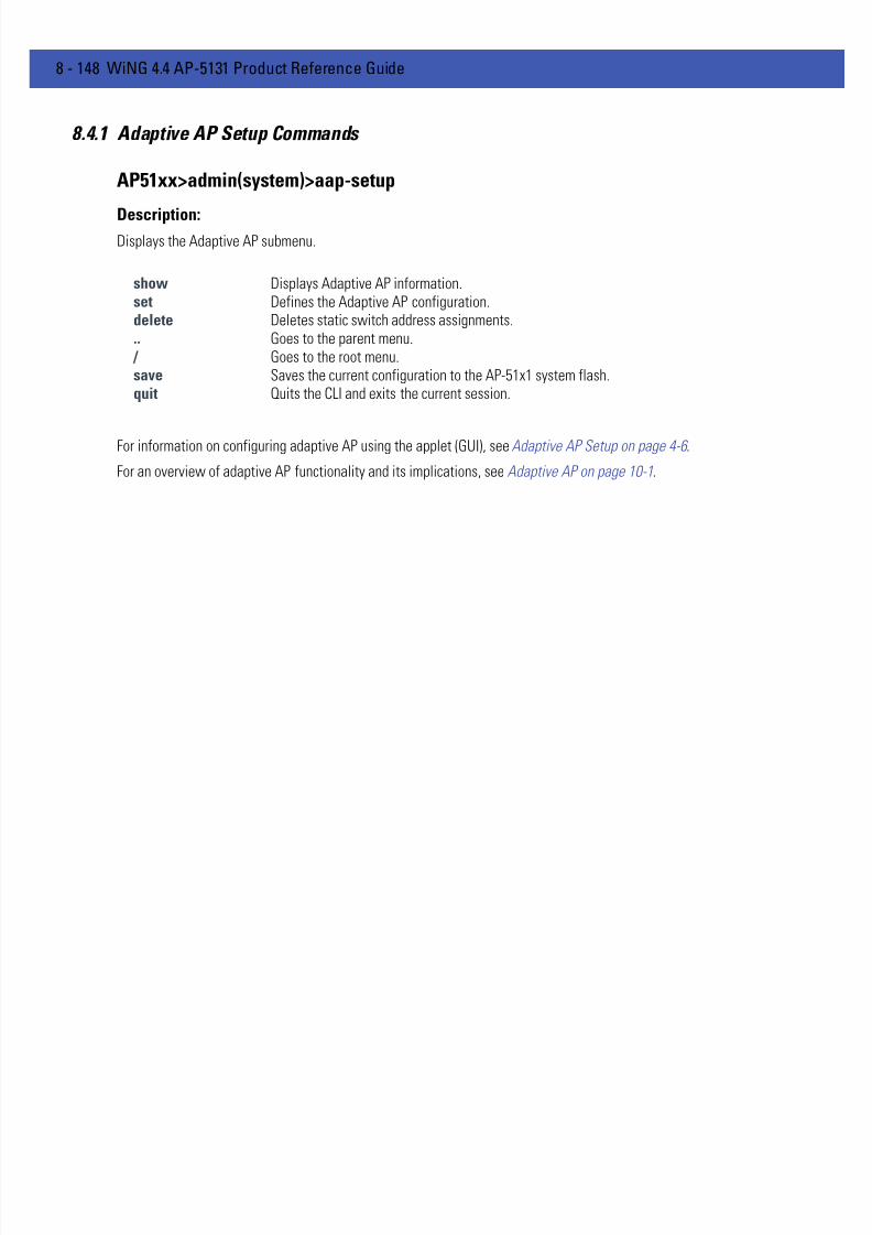
7/18/2019 Motorola AP 5131 Manual
http://slidepdf.com/reader/full/motorola-ap-5131-manual 418/613
8 - 148 WiNG 4.4 AP-5131 Product Reference Guide
8.4.1 Adaptive AP Setup Commands
AP51xx>admin(system)>aap-setup
Description:Displays the Adaptive AP submenu.
For information on configuring adaptive AP using the applet (GUI), see Adaptive AP Setup on page 4-6 .
For an overview of adaptive AP functionality and its implications, see Adaptive AP on page 10-1.
show Displays Adaptive AP information.set Defines the Adaptive AP configuration.delete Deletes static switch address assignments... Goes to the parent menu.
/ Goes to the root menu.save Saves the current configuration to the AP-51x1 system flash.quit Quits the CLI and exits the current session.
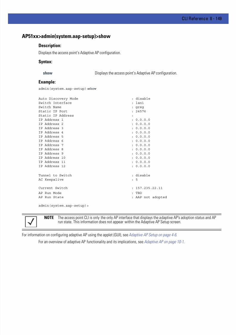
7/18/2019 Motorola AP 5131 Manual
http://slidepdf.com/reader/full/motorola-ap-5131-manual 419/613
CLI Reference 8 - 149
AP51xx>admin(system.aap-setup)>show
Description:
Displays the access point’s Adaptive AP configuration.
Syntax:
Example:
admin(system.aap-setup)>show
Auto Discovery Mode : disableSwitch Interface : lan1Switch Name : gregStatic IP Port : 24576
Static IP Address :IP Address 1 : 0.0.0.0IP Address 2 : 0.0.0.0IP Address 3 : 0.0.0.0IP Address 4 : 0.0.0.0IP Address 5 : 0.0.0.0IP Address 6 : 0.0.0.0IP Address 7 : 0.0.0.0IP Address 8 : 0.0.0.0IP Address 9 : 0.0.0.0IP Address 10 : 0.0.0.0IP Address 11 : 0.0.0.0IP Address 12 : 0.0.0.0
Tunnel to Switch : disable AC Keepalive : 5
Current Switch : 157.235.22.11
AP Run Mode : TBD AP Run State : AAP not adopted
admin(system.aap-setup)>
For information on configuring adaptive AP using the applet (GUI), see Adaptive AP Setup on page 4-6 .
For an overview of adaptive AP functionality and its implications, see Adaptive AP on page 10-1.
show Displays the access point’s Adaptive AP configuration.
NOTE The access point CLI is only the only AP interface that displays the adaptive AP’s adoption status and APrun state. This information does not appear within the Adaptive AP Setup screen.

7/18/2019 Motorola AP 5131 Manual
http://slidepdf.com/reader/full/motorola-ap-5131-manual 420/613
8 - 150 WiNG 4.4 AP-5131 Product Reference Guide
AP51xx>admin(system.aap-setup)>set
Description:
Sets AP-51x1’s Adaptive AP configuration.
Syntax:
For information on configuring adaptive AP using the applet (GUI), see Adaptive AP Setupon page 4-6.
For an overview of adaptive AP functionality and its implications, see Adaptive AP on page 10-1.
set auto-discovery Sets the switch auto-discovery mode (enable/disable).interface Defines the tunnel interface.ipadr Defines the switch IP address used.name Defines the switch name for DNS lookups.port Sets the port.passphrase Defines the pass phrase or key for switch connection.
tunnel-to-switch Enables/disables the tunnel between switch and access point.ac-keepalive Defines the keepalive interval.
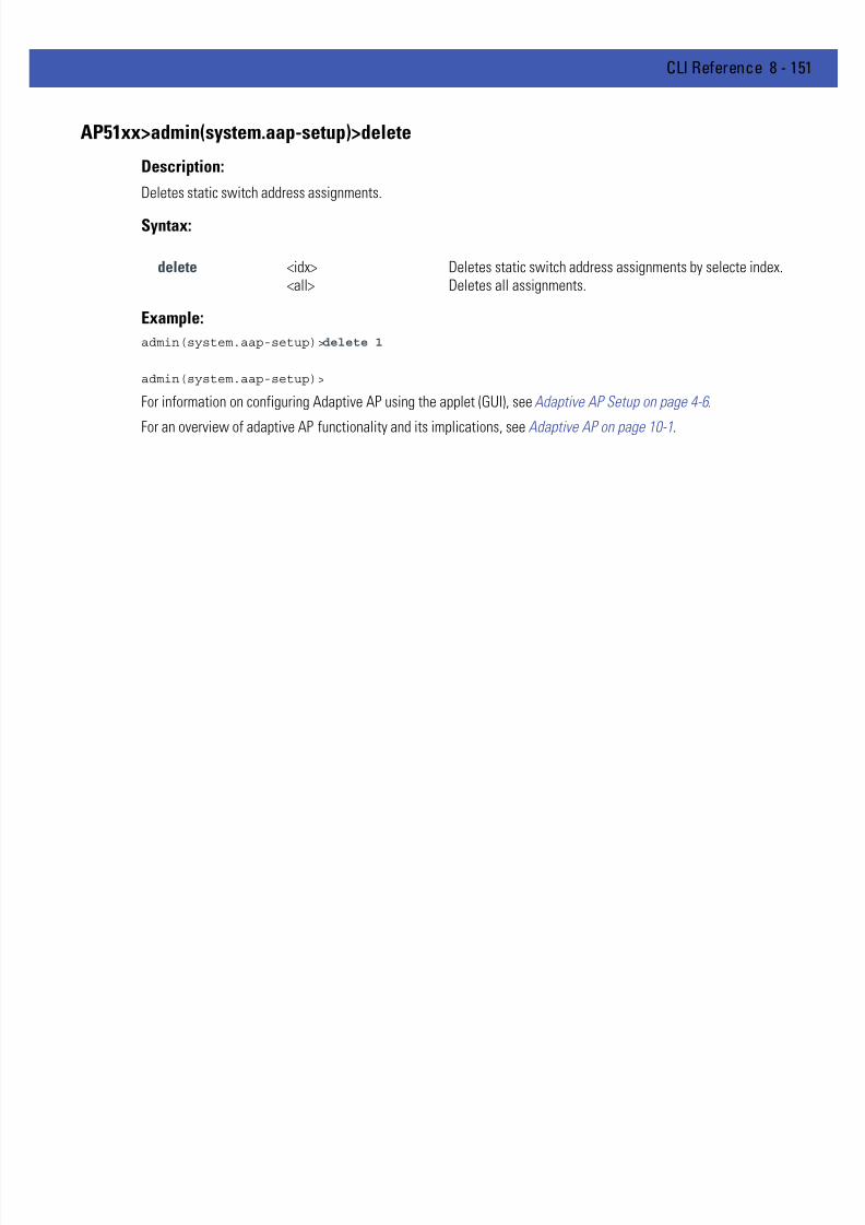
7/18/2019 Motorola AP 5131 Manual
http://slidepdf.com/reader/full/motorola-ap-5131-manual 421/613
CLI Reference 8 - 151
AP51xx>admin(system.aap-setup)>delete
Description:
Deletes static switch address assignments.
Syntax:
Example:
admin(system.aap-setup)>delete 1
admin(system.aap-setup)>
For information on configuring Adaptive AP using the applet (GUI), see Adaptive AP Setup on page 4-6 .
For an overview of adaptive AP functionality and its implications, see Adaptive AP on page 10-1.
delete <idx> Deletes static switch address assignments by selecte index.<all> Deletes all assignments.

7/18/2019 Motorola AP 5131 Manual
http://slidepdf.com/reader/full/motorola-ap-5131-manual 422/613
8 - 152 WiNG 4.4 AP-5131 Product Reference Guide
8.4.2 LLDP Commands
AP51xx>admin(system)>lldp
Description:Displays the LLDP sub menu.
For information on configuring LLDP using the applet (GUI), see Configuring LLDP Settings on page 4-35 .
show Displays LLDP information.set Sets LLDP parameters... Goes to the parent menu.
/ Goes to the root menu.save Saves the current configuration to the access point system flash.quit Quits the CLI and exits the current session.

7/18/2019 Motorola AP 5131 Manual
http://slidepdf.com/reader/full/motorola-ap-5131-manual 423/613
CLI Reference 8 - 153
AP51xx>admin (system.lldp)>show
Description:
Displays LLDP information.
Syntax:
Example:
admin(system.lldp)>show
LLDP Status : disable
LLDP Referesh Interval: 30
LLDP Holdtime Multiplier : 4
For information on configuring LLDP using the applet (GUI), see Configuring LLDP Settings on page 4-35 .
show Displays Adaptive AP information.

7/18/2019 Motorola AP 5131 Manual
http://slidepdf.com/reader/full/motorola-ap-5131-manual 424/613
8 - 154 WiNG 4.4 AP-5131 Product Reference Guide
AP51xx>admin (system.lldp)>set
Description:
Sets the LLDP configuration.
Syntax:
show Displays LLDP information.set Sets LLDP parameters... Goes to the parent menu.
/ Goes to the root menu.save Saves the current configuration to the access point system flash.quit Quits the CLI and exits the current session.

7/18/2019 Motorola AP 5131 Manual
http://slidepdf.com/reader/full/motorola-ap-5131-manual 425/613
CLI Reference 8 - 155
8.4.3 System Access Commands
AP51xx>admin(system)>access
Description:Displays the access point access submenu.
show Displays AP-51x1 system access capabilities.set Goes to the AP-51x1 system access submenu... Goes to the parent menu.
/ Goes to the root menu.save Saves the current configuration to the AP-51x1 system flash.quit Quits the CLI and exits the current session.

7/18/2019 Motorola AP 5131 Manual
http://slidepdf.com/reader/full/motorola-ap-5131-manual 426/613
8 - 156 WiNG 4.4 AP-5131 Product Reference Guide
AP51xx>admin(system.access)>set
Description:
Defines the permissions to access the AP-51x1 applet, CLI, SNMP as well as defining their timeout values.
Syntax:
For information on configuring access point access settings using the applet (GUI), see Configuring Data Access on page4-8 .
set applet Defines the applet HTTP/HTTPS access parameters.
app-timeout <minutes> Sets the applet timeout. Default is 300 Mins.
cli Defines CLI Telnet access parameters. Enables/disables access from lanand wan.
ssh Sets the CLI SSH access parameters.
trusted-host <mode>, <range><clear>
Enables/Disables global management access (snmp, http, https, telnetand ssh) for up to 8 addresses (hosts).
auth-timout <seconds> Disables the radio interface if no data activity is detected after theinterval defined. Default is 120 seconds.
inactive-timeout <minutes> Inactivity interval resulting in the AP terminating its connection.Default is 120 minutes.
snmp Sets SNMP access parameters.
admin-auth Designates a Radius server is used in the authentication verification.
server <ip> Specifies the IP address the Remote Dial-In User Service (RADIUS)server.
port <port#> Specifies the port on which the RADIUS server is listening. Default is1812.
secret <pw> Defines the shared secret password for RADIUS server authentication.mode <mode> Enables/disables the access point message mode.
msg Defines the access point login message text.
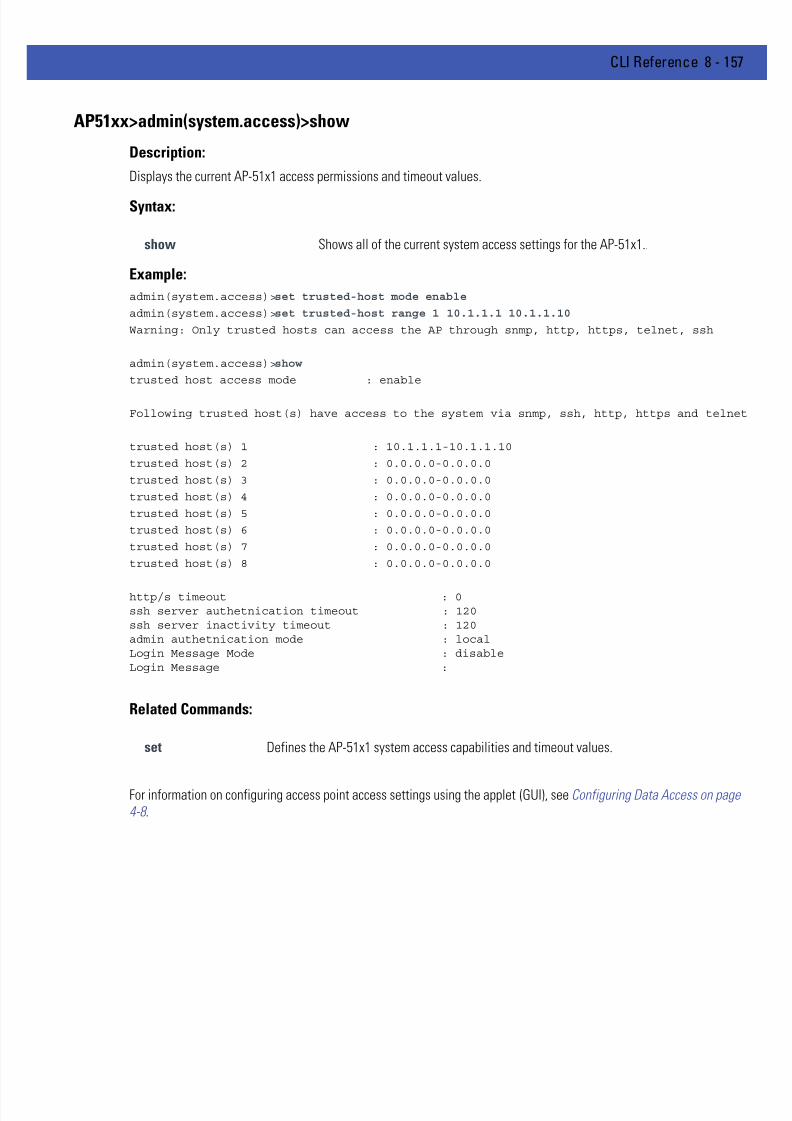
7/18/2019 Motorola AP 5131 Manual
http://slidepdf.com/reader/full/motorola-ap-5131-manual 427/613
CLI Reference 8 - 157
AP51xx>admin(system.access)>show
Description:
Displays the current AP-51x1 access permissions and timeout values.
Syntax:
Example:
admin(system.access)>set trusted-host mode enable
admin(system.access)>set trusted-host range 1 10.1.1.1 10.1.1.10
Warning: Only trusted hosts can access the AP through snmp, http, https, telnet, ssh
admin(system.access)>show
trusted host access mode : enable
Following trusted host(s) have access to the system via snmp, ssh, http, https and telnet
trusted host(s) 1 : 10.1.1.1-10.1.1.10
trusted host(s) 2 : 0.0.0.0-0.0.0.0
trusted host(s) 3 : 0.0.0.0-0.0.0.0
trusted host(s) 4 : 0.0.0.0-0.0.0.0
trusted host(s) 5 : 0.0.0.0-0.0.0.0
trusted host(s) 6 : 0.0.0.0-0.0.0.0
trusted host(s) 7 : 0.0.0.0-0.0.0.0
trusted host(s) 8 : 0.0.0.0-0.0.0.0
http/s timeout : 0ssh server authetnication timeout : 120ssh server inactivity timeout : 120admin authetnication mode : localLogin Message Mode : disableLogin Message :
Related Commands:
For information on configuring access point access settings using the applet (GUI), see Configuring Data Access on page4-8 .
show Shows all of the current system access settings for the AP-51x1..
set Defines the AP-51x1 system access capabilities and timeout values.

7/18/2019 Motorola AP 5131 Manual
http://slidepdf.com/reader/full/motorola-ap-5131-manual 428/613
8 - 158 WiNG 4.4 AP-5131 Product Reference Guide
8.4.4 System Certificate Management Commands
AP51xx>admin(system)>cmgr
Description:Displays the Certificate Manager submenu. The items available under this command include:
genreq Generates a Certificate Request.delself Deletes a Self Certificate.loadself Loads a Self Certificate signed by CA.listself Lists the self certificate loaded.loadca Loads trusted certificate from CA.delca Deletes the trusted certificate.listca Lists the trusted certificate loaded.showreq Displays a certificate request in PEM format.
delprivkey Deletes the private key.listprivkey Lists names of private keys.expcert Exports the certificaqte file.impcert Imports the certificate file... Goes to the parent menu.
/ Goes to the root menu.save Saves the configuration to system flash.quit Quits the CLI.
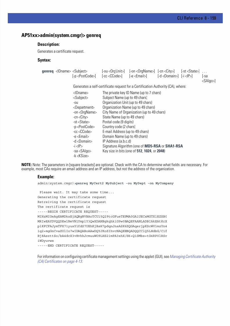
7/18/2019 Motorola AP 5131 Manual
http://slidepdf.com/reader/full/motorola-ap-5131-manual 429/613
CLI Reference 8 - 159
AP51xx>admin(system.cmgr)> genreq
Description:
Generates a certificate request.
Syntax:
NOTE: Note: The parameters in [square brackets] are optional. Check with the CA to determine what fields are necessary. For
example, most CAs require an email address and an IP address, but not the address of the organization.Example:
admin(system.cmgr)>genreq MyCert2 MySubject -ou MyDept -on MyCompany
Please wait. It may take some time...
Generating the certificate request
Retreiving the certificate request
The certificate request is
-----BEGIN CERTIFICATE REQUEST-----
MIHzMIGeAgEAMDkxEjAQBgNVBAoTCU15Q29tcGFueTEPMA0GA1UECxMGTXlEZXB0
MRIwEAYDVQQDEwlNeVN1YmplY3QwXDANBgkqhkiG9w0BAQEFAANLADBIAkEAtKcX
plKFCFAJymTFX71yuxY1fdS7UEhKjBsH7pdqnJnsASK6ZQGAqerjpKScWV1mzYn41q2+mgGnCvaZUlIo7wIDAQABoAAwDQYJKoZIhvcNAQEEBQADQQCClQ5LHdbG/C1f
Bj8AszttSo/bA4dcX3vHvhhJcmuuWO9LHS2imPA3xhX/d6+Q1SMbs+tG4RP0lRSr
iWDyuvwx
-----END CERTIFICATE REQUEST-----
For information on configuring certificate management settings using the applet (GUI), see Managing Certificate Authority(CA) Certificates on page 4-13 .
genreq <IDname> <Subject> [-ou <OrgUnit>] [-on <OrgName>] [-cn <City>] [-st <State>] . . .[-p <PostCode>] [-cc <CCode>] [-e <Email>] [-d <Domain>] [-i <IP>] [-sa
<SAlgo>]
Generates a self-certificate request for a Certification Authority (CA), where:
<IDname><Subject>-ou<Department>
-on <OrgName>-cn <City>-st <State>-p <PostCode>-cc <CCode>-e <Email>-d <Domain>-i <IP>-sa <SAlgo>-k <KSize>
The private key ID Name (up to 7 chars)Subject Name (up to 49 chars)Organization Unit (up to 49 chars)Organization Name (up to 49 chars)
City Name of Organization (up to 49 chars)State Name (up to 49 chars)Postal code (9 digits)Country code (2 chars)E-mail Address (up to 49 chars)Domain Name (up to 49 chars)IP Address (a.b.c.d)Signature Algorithm (one of MD5-RSA or SHA1-RSA Key size in bits (one of 512, 1024, or 2048)

7/18/2019 Motorola AP 5131 Manual
http://slidepdf.com/reader/full/motorola-ap-5131-manual 430/613
8 - 160 WiNG 4.4 AP-5131 Product Reference Guide
AP51xx>admin(system.cmgr)> delself
Description: )
Deletes a self certificate.
Syntax:
Example:
admin(system.cmgr)>delself MyCert2
For information on configuring self certificate settings using the applet (GUI), see Creating Self Certificates for Accessingthe VPN on page 4-14 .
delself <IDname> Deletes the self certificate named <IDname>.

7/18/2019 Motorola AP 5131 Manual
http://slidepdf.com/reader/full/motorola-ap-5131-manual 431/613
CLI Reference 8 - 161
AP51xx>admin(system.cmgr)> loadself
Description:
Loads a self certificate signed by the Certificate Authority.
Syntax:
For information on configuring self certificate settings using the applet (GUI), see Creating Self Certificates for Accessingthe VPN on page 4-14 .
loadself <IDname> Load the self certificate signed by the CA with name <IDname>.

7/18/2019 Motorola AP 5131 Manual
http://slidepdf.com/reader/full/motorola-ap-5131-manual 432/613
8 - 162 WiNG 4.4 AP-5131 Product Reference Guide
AP51xx>admin(system.cmgr)> listself
Description:
Lists the loaded self certificates.
Syntax:
For information on configuring self certificate settings using the applet (GUI), see Creating Self Certificates for Accessingthe VPN on page 4-14 .
listself Lists all self certificates that are loaded.

7/18/2019 Motorola AP 5131 Manual
http://slidepdf.com/reader/full/motorola-ap-5131-manual 433/613
CLI Reference 8 - 163
AP51xx>admin(system.cmgr)> loadca
Description:
Loads a trusted certificate from the Certificate Authority.
Syntax:
For information on configuring certificate settings using the applet (GUI), see Importing a CA Certificate on page 4-13 .
loadca Loads the trusted certificate (in PEM format) that is pasted into the command line.

7/18/2019 Motorola AP 5131 Manual
http://slidepdf.com/reader/full/motorola-ap-5131-manual 434/613
8 - 164 WiNG 4.4 AP-5131 Product Reference Guide
AP51xx>admin(system.cmgr)> delca
Description:
Deletes a trusted certificate.
Syntax:
For information on configuring certificate settings using the applet (GUI), see Importing a CA Certificate on page 4-13 .
delca <IDname> Deletes the trusted certificate.

7/18/2019 Motorola AP 5131 Manual
http://slidepdf.com/reader/full/motorola-ap-5131-manual 435/613
CLI Reference 8 - 165
AP51xx>admin(system.cmgr)> listca
Description:
Lists the loaded trusted certificate.
Syntax:
For information on configuring certificate settings using the applet (GUI), see Importing a CA Certificate on page 4-13 .
listca Lists the loaded trusted certificates.

7/18/2019 Motorola AP 5131 Manual
http://slidepdf.com/reader/full/motorola-ap-5131-manual 436/613
8 - 166 WiNG 4.4 AP-5131 Product Reference Guide
AP51xx>admin(system.cmgr)> showreq
Description:
Displays a certificate request in PEM format.
Syntax:
For information on configuring certificate settings using the applet (GUI), see Importing a CA Certificate on page 4-13 .
showreq <IDname> Displays a certificate request named <IDname> generated from the genreq comma

7/18/2019 Motorola AP 5131 Manual
http://slidepdf.com/reader/full/motorola-ap-5131-manual 437/613
CLI Reference 8 - 167
AP51xx>admin(system.cmgr)> delprivkey
Description:
Deletes a private key.
Syntax:
For information on configuring certificate settings using the applet (GUI), see Creating Self Certificates for Accessing theVPN on page 4-14 .
delprivkey <IDname> Deletes private key named <IDname>.

7/18/2019 Motorola AP 5131 Manual
http://slidepdf.com/reader/full/motorola-ap-5131-manual 438/613
8 - 168 WiNG 4.4 AP-5131 Product Reference Guide
AP51xx>admin(system.cmgr)> listprivkey
Description:
Lists the names of private keys.
Syntax:
For information on configuring certificate settings using the applet (GUI), see Importing a CA Certificate on page 4-13 .
listprivkey Lists all private keys.

7/18/2019 Motorola AP 5131 Manual
http://slidepdf.com/reader/full/motorola-ap-5131-manual 439/613
CLI Reference 8 - 169
AP51xx>admin(system.cmgr)> expcert
Description:
Exports the certificate file to a user defined location.
Syntax:
To export certificate information from an AP-5131 or AP-5181 model access point:
admin(system.cmgr)>expcert ?
<type> <file name> <cr> : type: ftp/tftp: file name: Certificate file name: Server options for this file are the same: as that for the configuration file
admin(system.cmgr)>expcert tftp AP-51x1certs.txt
To configue AP-5131 or AP-5181 certificate management settings while conducting a firmware update or restoring afactory default configuratrion:
admin(system.cmgr)> ?
genreq : generate a certificate requestdelself : deletes a signed certificateloadself : loads a signed certficiate signed by the CAlistself : lists the loaded signed self certificateloadca : loads the root CA certificatedelca : deletes the root CA certificate
listca : lists the loaded root CA certificateshowreq : displays certificate request in PEM formatdelprivkey : deletes the private keylistprivkey : lists the names of the private keysexpcert : exports the target certficate fileimpcert : imports the target certficate file(..) : goes to the parent menu/ : goes to the root menusave : saves the configuration to system flashquit : quits the CLI session
For information on configuring certificate settings using the applet (GUI), see Importing a CA Certificate on page 4-13 .
expcert Exports the access point’s CA or Self certificate file.

7/18/2019 Motorola AP 5131 Manual
http://slidepdf.com/reader/full/motorola-ap-5131-manual 440/613
8 - 170 WiNG 4.4 AP-5131 Product Reference Guide
AP51xx>admin(system.cmgr)> impcert
Description:
Imports the target certificate file.
Syntax:
To import certificate information from an AP-5131 or AP-5181 model access point:
admin(system.cmgr)>impcert ?
<type> <file name> <cr> : type: ftp/tftp: file name: Certificate file name: Server options for this file are the same: as that for the configuration file
admin(system.cmgr)>impcert tftp AP-51x1certs.txt
To configue AP-5131 or AP-5181 certificate management settings while conducting a firmware update or restoring afactory default configuratrion:
admin(system.cmgr)> ?
genreq : generate a certificate requestdelself : deletes a signed certificateloadself : loads a signed certficiate signed by the CAlistself : lists the loaded signed self certificateloadca : loads the root CA certificatedelca : deletes the root CA certificate
listca : lists the loaded root CA certificateshowreq : displays certificate request in PEM formatdelprivkey : deletes the private keylistprivkey : lists the names of the private keysexpcert : exports the target certficate fileimpcert : imports the target certficate file(..) : goes to the parent menu/ : goes to the root menusave : saves the configuration to system flashquit : quits the CLI session
For information on configuring certificate settings using the applet (GUI), see Importing a CA Certificate on page 4-13 .
impcert Imports the target certificate file.
7/18/2019 Motorola AP 5131 Manual
http://slidepdf.com/reader/full/motorola-ap-5131-manual 441/613
CLI Reference 8 - 171
8.4.5 System SNMP Commands
AP51xx>admin(system)> snmp
Description:Displays the SNMP submenu. The items available under this command are shown below.
access Goes to the SNMP access submenu. traps Goes to the SNMP traps submenu... Goes to the parent menu.
/ Goes to the root menu.save Saves the configuration to system flash.quit Quits the CLI.

7/18/2019 Motorola AP 5131 Manual
http://slidepdf.com/reader/full/motorola-ap-5131-manual 442/613
8 - 172 WiNG 4.4 AP-5131 Product Reference Guide
8.4.5.1 System SNMP Access Commands
AP51xx>admin(system.snmp.access)
Description:Displays the SNMP Access menu. The items available under this command are shown below.
show Shows SNMP v3 engine ID.add Adds SNMP access entries.delete Deletes SNMP access entries.list Lists SNMP access entries... Goes to the parent menu.
/ Goes to the root menu.save Saves the configuration to system flash.quit Quits the CLI.

7/18/2019 Motorola AP 5131 Manual
http://slidepdf.com/reader/full/motorola-ap-5131-manual 443/613
CLI Reference 8 - 173
AP51xx>admin(system.snmp.access)> show
Description:
Shows the SNMP v3 engine ID.
Syntax:
Example:
admin(system.snmp.access)>show eid
AP-51x1 snmp v3 engine id : 000001846B8B4567F871AC68
admin(system.snmp.access)>
For information on configuring SNMP access settings using the applet (GUI), see Configuring SNMP Access Control onpage 4-25 .
show eid Shows the SNMP v3 Engine ID.

7/18/2019 Motorola AP 5131 Manual
http://slidepdf.com/reader/full/motorola-ap-5131-manual 444/613
8 - 174 WiNG 4.4 AP-5131 Product Reference Guide
AP51xx>admin(system.snmp.access)> add
Description:
Adds SNMP access entries for specific v1v2 and v3 user definitions.
Syntax:
For information on configuring SNMP access settings using the applet (GUI), see Configuring SNMP Access Control onpage 4-25 .
add acl <ip1> <ip2> Adds an entry to the SNMP access control list with <ip1> as the starting IP addressand <ip2> and as the ending IP address.
v1v2c <comm> <access> <oid>
: comm - community string 1 to 31 characters
: access - read/write access - (ro,rw)
: oid - string 1 to 127 chars - E.g. 1.3.6.1
v3<user>
<access> <oid><sec>
<auth> <pass1> <priv> <pass2>
: user - username 1 to 31 characters
: access - read/write access - (ro,rw)
: oid - string 1 to 127 chars - E.g. 1.3.6.1
: sec - security - (none,auth,auth/priv)
: auth - algorithm - (md5,sha1)
: (required only if sec is - auth,auth/priv)
: pass1 - auth password - 8 to 31 chars
: (required only if sec is 'auth,auth/priv')
: priv - algorithm - (des, aes)
: (required only if sec is 'auth/priv')
: pass2 - privacy password - 8 to 31 chars
: (required only if sec is 'auth/priv')
The following parameters must be specified if <sec> is not none:Authentication type <auth> set to md5 or sha1 Authentication password <pass1> (8 to 31 chars)
The following parameters must be specified if <sec> is set to auth/priv:Privacy algorithm set to des or aes Privacy password <pass2> (8 to 31 chars)
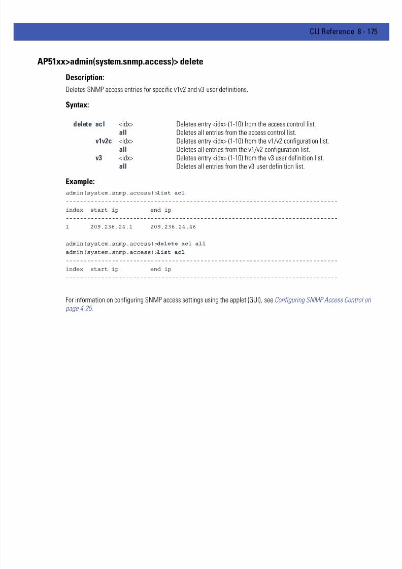
7/18/2019 Motorola AP 5131 Manual
http://slidepdf.com/reader/full/motorola-ap-5131-manual 445/613
CLI Reference 8 - 175
AP51xx>admin(system.snmp.access)> delete
Description:
Deletes SNMP access entries for specific v1v2 and v3 user definitions.
Syntax:
Example:
admin(system.snmp.access)>list acl
-----------------------------------------------------------------------------
index start ip end ip
-----------------------------------------------------------------------------
1 209.236.24.1 209.236.24.46
admin(system.snmp.access)>delete acl all
admin(system.snmp.access)>list acl
-----------------------------------------------------------------------------
index start ip end ip
-----------------------------------------------------------------------------
For information on configuring SNMP access settings using the applet (GUI), see Configuring SNMP Access Control onpage 4-25 .
delete acl <idx> Deletes entry <idx> (1-10) from the access control list.all Deletes all entries from the access control list.
v1v2c <idx> Deletes entry <idx> (1-10) from the v1/v2 configuration list.all Deletes all entries from the v1/v2 configuration list.
v3 <idx> Deletes entry <idx> (1-10) from the v3 user definition list.all Deletes all entries from the v3 user definition list.
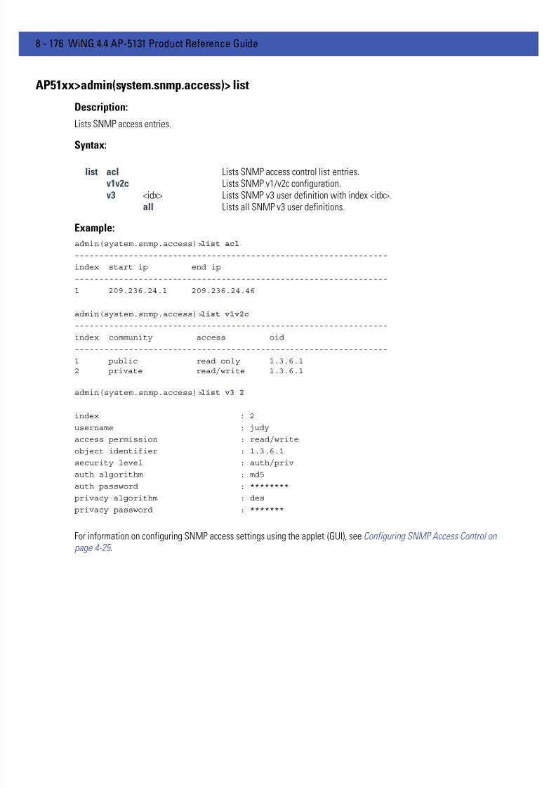
7/18/2019 Motorola AP 5131 Manual
http://slidepdf.com/reader/full/motorola-ap-5131-manual 446/613
8 - 176 WiNG 4.4 AP-5131 Product Reference Guide
AP51xx>admin(system.snmp.access)> list
Description:
Lists SNMP access entries.
Syntax:
Example:
admin(system.snmp.access)>list acl
----------------------------------------------------------------
index start ip end ip
----------------------------------------------------------------
1 209.236.24.1 209.236.24.46
admin(system.snmp.access)>list v1v2c
----------------------------------------------------------------
index community access oid
----------------------------------------------------------------
1 public read only 1.3.6.12 private read/write 1.3.6.1
admin(system.snmp.access)>list v3 2
index : 2
username : judy
access permission : read/write
object identifier : 1.3.6.1
security level : auth/priv
auth algorithm : md5
auth password : ********
privacy algorithm : des
privacy password : *******
For information on configuring SNMP access settings using the applet (GUI), see Configuring SNMP Access Control on
page 4-25 .
list acl Lists SNMP access control list entries.v1v2c Lists SNMP v1/v2c configuration.v3 <idx> Lists SNMP v3 user definition with index <idx>.
all Lists all SNMP v3 user definitions.

7/18/2019 Motorola AP 5131 Manual
http://slidepdf.com/reader/full/motorola-ap-5131-manual 447/613
CLI Reference 8 - 177
8.4.5.2 System SNMP Traps Commands
AP51xx>admin(system.snmp.traps)
Description:Displays the SNMP traps submenu. The items available under this command are shown below.
show Shows SNMP trap parameters.set Sets SNMP trap parameters.add Adds SNMP trap entries.delete Deletes SNMP trap entries.list Lists SNMP trap entries... Goes to the parent menu.
/ Goes to the root menu.save Saves the configuration to system flash.
quit Quits the CLI.

7/18/2019 Motorola AP 5131 Manual
http://slidepdf.com/reader/full/motorola-ap-5131-manual 448/613
8 - 178 WiNG 4.4 AP-5131 Product Reference Guide
AP51xx>admin(system.snmp.traps)> show
Description:
Shows SNMP trap parameters.
Syntax:
Example:
admin(system.snmp.traps)>show trap
SNMP MU Traps
mu associated : enable
mu unassociated : disable
mu denied association : disable
mu denied authentication : disable
SNMP Traps
snmp authentication failure : disable
snmp acl violation : disable
SNMP Network Traps
physical port status change : enable
denial of service : enable
denial of service trap rate limit : 10 seconds
SNMP System Traps
system cold start : disable
system config changed : disable
rogue ap detection : disable
ap radar detection : disable
wpa counter measure : disable
mu hotspot status : disable
vlan : disable
lan monitor : disable
DynDNS Update : enable
Health Check event : disable
For information on configuring SNMP traps using the applet (GUI), see Enabling SNMP Traps on page 4-26 .
show trap Shows SNMP trap parameter settings.rate-trap Shows SNMP rate-trap parameter settings.

7/18/2019 Motorola AP 5131 Manual
http://slidepdf.com/reader/full/motorola-ap-5131-manual 449/613
CLI Reference 8 - 179
AP51xx>admin(system.snmp.traps)> set
Description:
Sets SNMP trap parameters.
Syntax:
set mu-assoc enable /disable
Enables/disables the MU associated trap.
mu-unassoc enable /disable
Enables/disables the MU unassociated trap.
mu-deny-assoc enable /disable
Enables/disables the MU association denied trap.
mu-deny-auth enable /disable
Enables/disables the MU authentication denied trap.
snmp-auth enable /disable
Enables/disables the authentication failure trap.
snmp-acl enable /disable
Enables/disables the SNMP ACL violation trap.
port enable /disable
Enables/disables the physical port status trap.
dos-attack enable /disable
Enables/disables the denial of service trap.
dyndns-update enable /disable
Enables/disables dyndns update trap.
interval <rate> Sets denial of service trap interval.
cold enable /disable
Enables/disables the system cold start trap.
cfg enable /disable
Enables/disables a configuration changes trap.
rogue-ap enable /disable
Enables/disables a trap when a rogue-ap is detected.
ap-radar enable /disable
Enables/disables the AP Radar Detection trap.
wpa-counter enable /disable
Enables/disables the WPA counter measure trap.
hotspot-mu-status enable /disable
Enables/disables the hotspot mu status trap.
vlan enable /disable
Enables/disables VLAN traps.
lan-monitor enable /disable
Enables/disables LAN monitor traps.

7/18/2019 Motorola AP 5131 Manual
http://slidepdf.com/reader/full/motorola-ap-5131-manual 450/613
8 - 180 WiNG 4.4 AP-5131 Product Reference Guide
For information on configuring SNMP traps using the applet (GUI), see Configuring Specific SNMP Traps on page 4-28 .
rate <rate> <scope> <value> Sets the particular <rate> to monitor to <value> giventhe indicated <scope>. See table below for informationon the possible values for <rate>, <scope>, and<value>.
min-pkt <pkt> Sets the minimum number of packets required for ratetraps to fire (1-65535).
health-check-event
enable/ disable
Enables/disables the health check event trap.
all enable/ disable
Enables/disables all traps
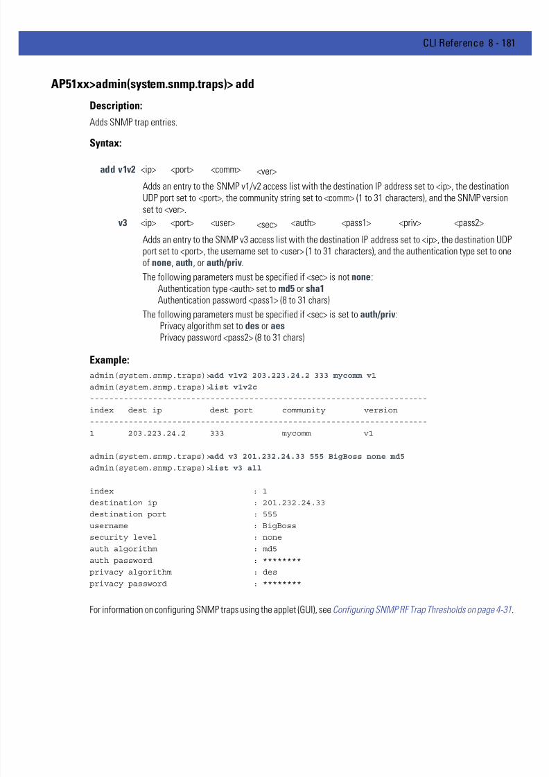
7/18/2019 Motorola AP 5131 Manual
http://slidepdf.com/reader/full/motorola-ap-5131-manual 451/613
CLI Reference 8 - 181
AP51xx>admin(system.snmp.traps)> add
Description:
Adds SNMP trap entries.
Syntax:
Example:
admin(system.snmp.traps)>add v1v2 203.223.24.2 333 mycomm v1
admin(system.snmp.traps)>list v1v2c
----------------------------------------------------------------------
index dest ip dest port community version
----------------------------------------------------------------------
1 203.223.24.2 333 mycomm v1
admin(system.snmp.traps)>add v3 201.232.24.33 555 BigBoss none md5
admin(system.snmp.traps)>list v3 all
index : 1
destination ip : 201.232.24.33
destination port : 555
username : BigBoss
security level : none
auth algorithm : md5
auth password : ********
privacy algorithm : des
privacy password : ********
For information on configuring SNMP traps using the applet (GUI), see Configuring SNMP RF Trap Thresholds on page 4-31.
add v1v2 <ip> <port> <comm> <ver>
Adds an entry to the SNMP v1/v2 access list with the destination IP address set to <ip>, the destinationUDP port set to <port>, the community string set to <comm> (1 to 31 characters), and the SNMP versionset to <ver>.
v3 <ip> <port> <user> <sec> <auth> <pass1> <priv> <pass2>
Adds an entry to the SNMP v3 access list with the destination IP address set to <ip>, the destination UDPport set to <port>, the username set to <user> (1 to 31 characters), and the authentication type set to oneof none, auth, or auth/priv.
The following parameters must be specified if <sec> is not none:Authentication type <auth> set to md5 or sha1 Authentication password <pass1> (8 to 31 chars)
The following parameters must be specified if <sec> is set to auth/priv:Privacy algorithm set to des or aes Privacy password <pass2> (8 to 31 chars)
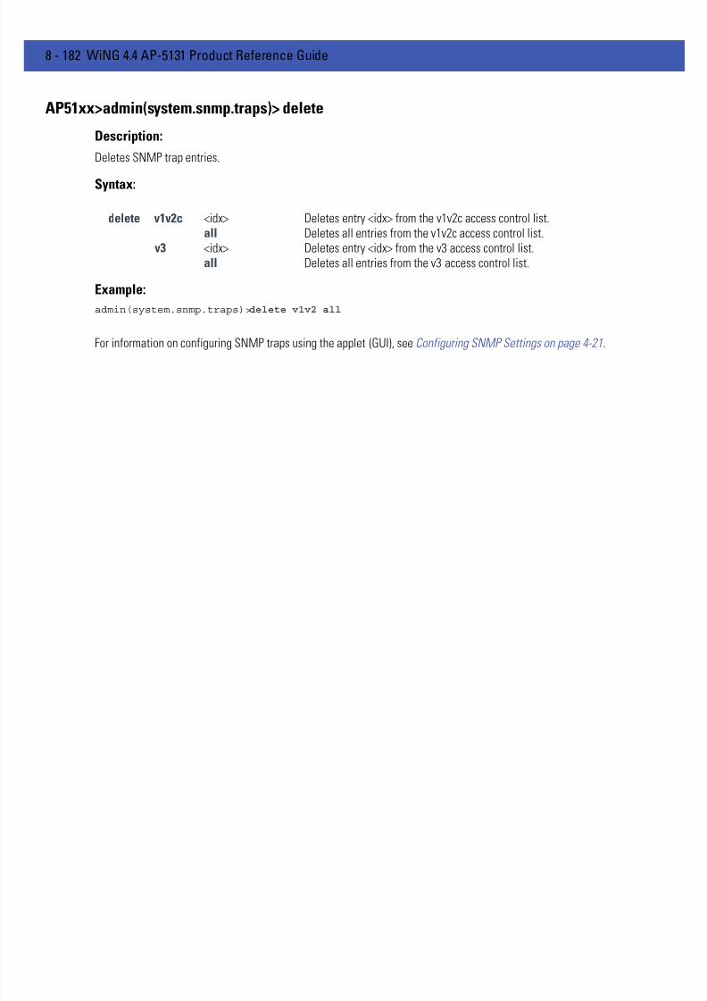
7/18/2019 Motorola AP 5131 Manual
http://slidepdf.com/reader/full/motorola-ap-5131-manual 452/613
8 - 182 WiNG 4.4 AP-5131 Product Reference Guide
AP51xx>admin(system.snmp.traps)> delete
Description:
Deletes SNMP trap entries.
Syntax:
Example:
admin(system.snmp.traps)>delete v1v2 all
For information on configuring SNMP traps using the applet (GUI), see Configuring SNMP Settings on page 4-21.
delete v1v2c <idx> Deletes entry <idx> from the v1v2c access control list.all Deletes all entries from the v1v2c access control list.
v3 <idx> Deletes entry <idx> from the v3 access control list.all Deletes all entries from the v3 access control list.
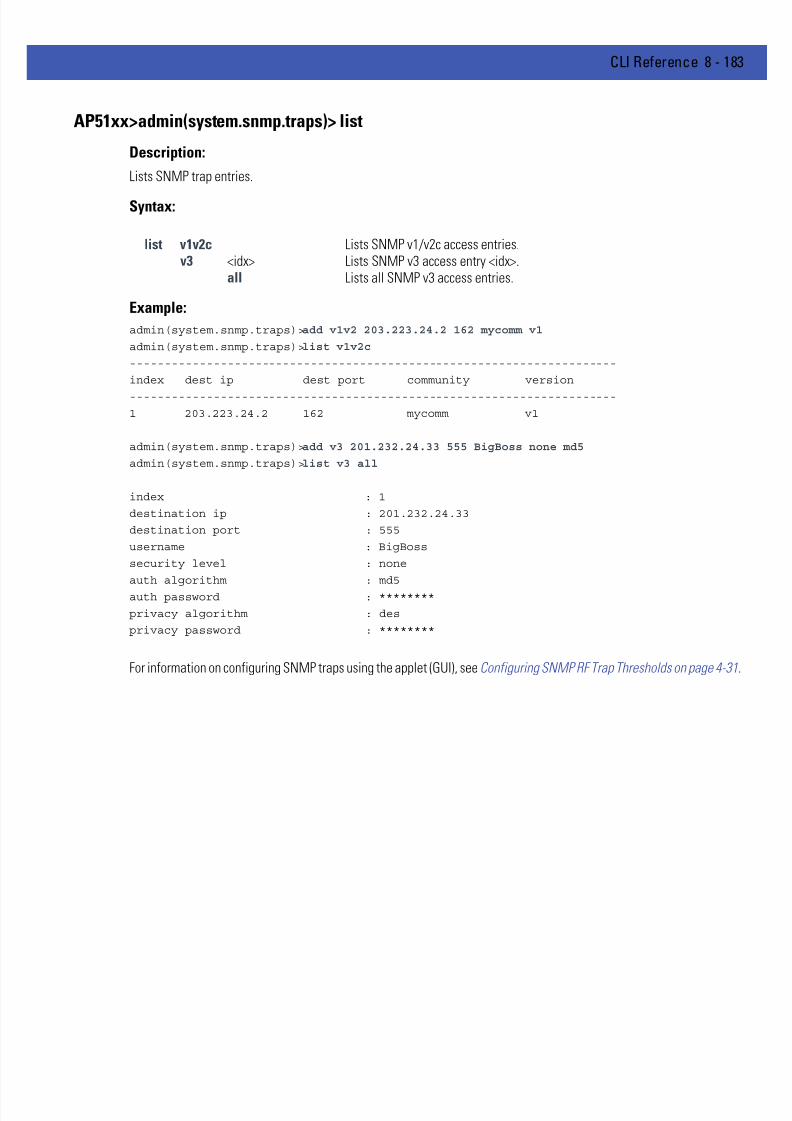
7/18/2019 Motorola AP 5131 Manual
http://slidepdf.com/reader/full/motorola-ap-5131-manual 453/613
CLI Reference 8 - 183
AP51xx>admin(system.snmp.traps)> list
Description:
Lists SNMP trap entries.
Syntax:
Example:
admin(system.snmp.traps)>add v1v2 203.223.24.2 162 mycomm v1
admin(system.snmp.traps)>list v1v2c
----------------------------------------------------------------------
index dest ip dest port community version
----------------------------------------------------------------------
1 203.223.24.2 162 mycomm v1
admin(system.snmp.traps)>add v3 201.232.24.33 555 BigBoss none md5
admin(system.snmp.traps)>list v3 all
index : 1
destination ip : 201.232.24.33
destination port : 555
username : BigBoss
security level : none
auth algorithm : md5
auth password : ********
privacy algorithm : des
privacy password : ********
For information on configuring SNMP traps using the applet (GUI), see Configuring SNMP RF Trap Thresholds on page 4-31.
list v1v2c Lists SNMP v1/v2c access entries.v3 <idx> Lists SNMP v3 access entry <idx>.
all Lists all SNMP v3 access entries.

7/18/2019 Motorola AP 5131 Manual
http://slidepdf.com/reader/full/motorola-ap-5131-manual 454/613
8 - 184 WiNG 4.4 AP-5131 Product Reference Guide
8.4.6 System User Database Commands
AP51xx>admin(system)> userdb
Description:Goes to the user database submenu.
Syntax:
For information on configuring User Database permissions using the applet (GUI), see Defining User Access Permissionsby Group on page 6-62 .
user Goes to the user submenu.group Goes to the group submenu.save Saves the configuration to system flash... Goes to the parent menu.
/ Goes to the root menu.

7/18/2019 Motorola AP 5131 Manual
http://slidepdf.com/reader/full/motorola-ap-5131-manual 455/613
CLI Reference 8 - 185
8.4.6.1 Adding and Removing Users from the User Databse
AP51xx>admin(system.userdb)> user
Description:Adds and remvoves users from the user database and defines user passwords.
Syntax:
For information on configuring User Database permissions using the applet (GUI), see Defining User Access Permissionsby Group on page 6-62 .
add Adds a new user.delete Deletes a new user.clearall Removes all existing user IDs from the system.set Sets a password for a user.show Displays the current user database configuration.save Saves the configuration to system flash.
.. Goes to the parent menu. / Goes to the root menu.

7/18/2019 Motorola AP 5131 Manual
http://slidepdf.com/reader/full/motorola-ap-5131-manual 456/613
8 - 186 WiNG 4.4 AP-5131 Product Reference Guide
AP51xx>admin(system.userdb.user)> add
Description:
Adds a new user to the user database.
Syntax:
Example:
admin(system.userdb.user>add george password
admin(system.userdb.user>
For information on configuring User Database permissions using the applet (GUI), see Defining User Access Permissionsby Group on page 6-62 .
add Adds a new user to the user database.
7/18/2019 Motorola AP 5131 Manual
http://slidepdf.com/reader/full/motorola-ap-5131-manual 457/613
CLI Reference 8 - 187
AP51xx>admin(system.userdb.user)> delete
Description:
Removes a new user to the user database.
Syntax:
Example:
admin(system.userdb.user>delete george
admin(system.userdb.user>
For information on configuring User Database permissions using the applet (GUI), see Defining User Access Permissionsby Group on page 6-62 .
delete Removes a new user to the user database.
7/18/2019 Motorola AP 5131 Manual
http://slidepdf.com/reader/full/motorola-ap-5131-manual 458/613
8 - 188 WiNG 4.4 AP-5131 Product Reference Guide
AP51xx>admin(system.userdb.user)>clearall
Description:
Removes all existing user IDs from the system.
Syntax:
Example:
admin(system.userdb.user>clearall
admin(system.userdb.user>
For information on configuring User Database permissions using the applet (GUI), see Defining User Access Permissionsby Group on page 6-62 .
clearall Removes all existing user IDs from the system.
7/18/2019 Motorola AP 5131 Manual
http://slidepdf.com/reader/full/motorola-ap-5131-manual 459/613
CLI Reference 8 - 189
AP51xx>admin(system.userdb.user)>set
Description:
Sets a password for a user..
Syntax:
Example:
admin(system.userdb.user>set george password
admin(system.userdb.user>
For information on configuring User Database permissions using the applet (GUI), see Defining User Access Permissionsby Group on page 6-62 .
set <user> <pw> Sets a password for a specific user.

7/18/2019 Motorola AP 5131 Manual
http://slidepdf.com/reader/full/motorola-ap-5131-manual 460/613
8 - 190 WiNG 4.4 AP-5131 Product Reference Guide
8.4.6.2 Adding and Removing Groups from the User Databse
AP51xx>admin(system.userdb)> group
Description:Adds and remvoves groups from the user database.
Syntax:
For information on configuring User Database permissions using the applet (GUI), see Defining User Access Permissionsby Group on page 6-62 .
create Creates a group name.delete Deletes a group name.clearall Removes all existing group names from the system.add Adds a user to an existing group.remove Removes a user from an existing group.show Displays existing groups.
save Saves the configuration to system flash... Goes to the parent menu.
/ Moves back to root menu.

7/18/2019 Motorola AP 5131 Manual
http://slidepdf.com/reader/full/motorola-ap-5131-manual 461/613
CLI Reference 8 - 191
AP51xx>admin(system.userdb.group> create
Description:
Creates a group name. Once defined, users can be added to the group.
Syntax:
Example:
admin(system.userdb.group>create 2
admin(system.userdb.group>
For information on configuring User Database permissions using the applet (GUI), see Defining User Access Permissionsby Group on page 6-62 .
create Creates a group name. Once defined, users can be added to the group.

7/18/2019 Motorola AP 5131 Manual
http://slidepdf.com/reader/full/motorola-ap-5131-manual 462/613
8 - 192 WiNG 4.4 AP-5131 Product Reference Guide
AP51xx>admin(system.userdb.group> delete
Description:
Deletes an existing group.
Syntax:
Example:
admin(system.userdb.group>delete 2
admin(system.userdb.group>
For information on configuring User Database permissions using the applet (GUI), see Defining User Access Permissionsby Group on page 6-62 .
delete Deletes an existing group.

7/18/2019 Motorola AP 5131 Manual
http://slidepdf.com/reader/full/motorola-ap-5131-manual 463/613
CLI Reference 8 - 193
AP51xx>admin(system.userdb.group> clearall
Description:
Removes all existing group names from the system.
Syntax:
Example:
admin(system.userdb.group>clearall
admin(system.userdb.group>
For information on configuring User Database permissions using the applet (GUI), see Defining User Access Permissionsby Group on page 6-62 .
clearall Removes all existing group names from the system.

7/18/2019 Motorola AP 5131 Manual
http://slidepdf.com/reader/full/motorola-ap-5131-manual 464/613
8 - 194 WiNG 4.4 AP-5131 Product Reference Guide
AP51xx>admin(system.userdb.group> add
Description:
Adds a user to an existing group.
Syntax:
Example:
admin(system.userdb.group>add lucy group x
admin(system.userdb.group>
For information on configuring User Database permissions using the applet (GUI), see Defining User Access Permissionsby Group on page 6-62 .
add <userid> <group> Adds a user <userid> to an existing group <group>.
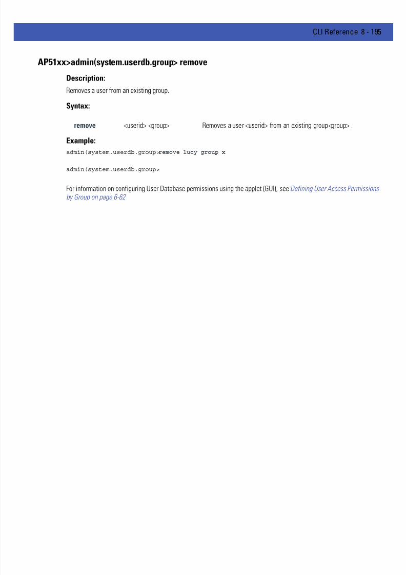
7/18/2019 Motorola AP 5131 Manual
http://slidepdf.com/reader/full/motorola-ap-5131-manual 465/613
CLI Reference 8 - 195
AP51xx>admin(system.userdb.group> remove
Description:
Removes a user from an existing group.
Syntax:
Example:
admin(system.userdb.group>remove lucy group x
admin(system.userdb.group>
For information on configuring User Database permissions using the applet (GUI), see Defining User Access Permissionsby Group on page 6-62
remove <userid> <group> Removes a user <userid> from an existing group<group> .

7/18/2019 Motorola AP 5131 Manual
http://slidepdf.com/reader/full/motorola-ap-5131-manual 466/613
8 - 196 WiNG 4.4 AP-5131 Product Reference Guide
AP51xx>admin(system.userdb.group> show
Description:
Displays existing groups.
Syntax:
Example:
admin(system.userdb.group>show groups
List of Group Names
: engineering
: marketing
: demo room
admin(system.userdb.group>
For information on configuring User Database permissions using the applet (GUI), see Defining User Access Permissionsby Group on page 6-62 .
show Displays existing groups and users,users Displays configured user IDs for a group.groups Displays configured groups.

7/18/2019 Motorola AP 5131 Manual
http://slidepdf.com/reader/full/motorola-ap-5131-manual 467/613
CLI Reference 8 - 197
8.4.7 System Radius Commands
AP51xx>admin(system)> radius
Description:Goes to the Radius system submenu.
Syntax:
For information on configuring Radius using the applet (GUI), see Configuring User Authentication on page 6-54 .
eap Goes to the EAP submenu.policy Goes to the access policy submenu.ldap Goes to the LDAP submenu.proxy Goes to the proxy submenu.client Goes to the client submenu.set Sets Radius parameters.
show Displays Radius parameters.save Saves the configuration to system flash.quit Quits the CLI... Goes to the parent menu.
/ Goes to the root menu.

7/18/2019 Motorola AP 5131 Manual
http://slidepdf.com/reader/full/motorola-ap-5131-manual 468/613
8 - 198 WiNG 4.4 AP-5131 Product Reference Guide
AP51xx>admin(system.radius)> set/show
Description:
Sets or displays the Radius user database.
Syntax:
Example:
admin(system.radius)>set database local
admin(system.radius)>show all
Database : local
admin(system.radius)>
For information on configuring Radius using the applet (GUI), see Configuring User Authentication on page 6-54 .
set Sets the Radius user database.show all Displays the Radius user database.

7/18/2019 Motorola AP 5131 Manual
http://slidepdf.com/reader/full/motorola-ap-5131-manual 469/613
CLI Reference 8 - 199
8.4.7.1 RADIUS EAP Commands
AP51xx>admin(system.radius)> eap
Description:Goes to the EAP submenu.
Syntax:
For information on configuring EAP Radius using the applet (GUI), see Configuring User Authentication on page 6-54 .
peap Goes to the Peap submenu. ttls Goes to the TTLS submenu.import Imports the requested EAP certificates.set Defines EAP parameters.show Displays the EAP configuration.save Saves the configuration to system flash.
quit Quits the CLI... Goes to the parent menu.
/ Goes to the root menu.

7/18/2019 Motorola AP 5131 Manual
http://slidepdf.com/reader/full/motorola-ap-5131-manual 470/613
8 - 200 WiNG 4.4 AP-5131 Product Reference Guide
AP51xx>admin(system.radius.eap)> peap
Description:
Goes to the Peap submenu.
Syntax:
For information on configuring PEAP Radius using the applet (GUI), see Configuring User Authentication on page 6-54 .
set Defines Peap parameters.show Displays the Peap configuration.save Saves the configuration to system flash.quit Quits the CLI... Goes to the parent menu.
/ Goes to the root menu.

7/18/2019 Motorola AP 5131 Manual
http://slidepdf.com/reader/full/motorola-ap-5131-manual 471/613
CLI Reference 8 - 201
AP51xx>admin(system.radius.eap.peap> set/show
Description:
Defines and displays Peap parameters
Syntax:
Example:
admin(system.radius.eap.peap)>set auth gtc
admin(system.radius.eap.peap)>show
PEAP Auth Type : gtc
For information on configuring EAP PEAP Radius values using the applet (GUI), see Configuring User Authentication onpage 6-54 .
set Sets the Peap authentication <type>.show Displays the Peap authentication type.

7/18/2019 Motorola AP 5131 Manual
http://slidepdf.com/reader/full/motorola-ap-5131-manual 472/613
8 - 202 WiNG 4.4 AP-5131 Product Reference Guide
AP51xx>admin(system.radius.eap)> ttls
Description:
Goes to the TTLS submenu.
Syntax:
For information on configuring EAP TTLS Radius values using the applet (GUI), see Configuring User Authentication on page6-54 .
set Defines TTLS parameters.show Displays the TTLS configuration.save Saves the configuration to system flash.quit Quits the CLI... Goes to the parent menu.
/ Goes to the root menu.

7/18/2019 Motorola AP 5131 Manual
http://slidepdf.com/reader/full/motorola-ap-5131-manual 473/613
CLI Reference 8 - 203
AP51xx>admin(system.radius.eap.ttls> set/show
Description:
Defines and displays TTLS parameters
Syntax:
Example:
admin(system.radius.eap.ttls)>set auth pap
admin(system.radius.eap.ttls)>show
TTLS Auth Type : gtc
For information on configuring EAP TTLS Radius values using the applet (GUI), see Configuring User Authentication on page6-54 .
set Sets the TTLS authentication <type>.show Displays the TTLS authentication type.

7/18/2019 Motorola AP 5131 Manual
http://slidepdf.com/reader/full/motorola-ap-5131-manual 474/613
8 - 204 WiNG 4.4 AP-5131 Product Reference Guide
8.4.7.2 RADIUS Policy Commands
AP51xx>admin(system.radius)> policy
Description:Goes to the access policy submenu.
Syntax:
For information on configuring Radius access policies using the applet (GUI), see Configuring User Authentication on page6-54 .
set Sets a group’s WLAN access policy.access-time Goes to the time based login submenu.show Displays the group’s access policy.save Saves the configuration to system flash.quit Quits the CLI... Goes to the parent menu.
/ Goes to the root menu.

7/18/2019 Motorola AP 5131 Manual
http://slidepdf.com/reader/full/motorola-ap-5131-manual 475/613
CLI Reference 8 - 205
AP51xx>admin(system.radius.policy> set
Description:
Defines the group’s WLAN access policy.
Syntax:
Example:
admin(system.radius.policy)>set engineering 16
admin(system.radius.policy)>
For information on configuring Radius WLAN policy values using the applet (GUI), see Configuring User Authentication onpage 6-54 .
set <group name><wlan name>
Defines the group’s <group name> WLAN access policy (defined as a string).

7/18/2019 Motorola AP 5131 Manual
http://slidepdf.com/reader/full/motorola-ap-5131-manual 476/613
8 - 206 WiNG 4.4 AP-5131 Product Reference Guide
AP51xx>admin(system.radius.policy> access-time
Description: set
Goes to the time-based login submenu.
Syntax:
Example:
admin(system.radius.policy.access-time)>show
List of Access Policies
1 : Tue0830-2200, We2000-2300, Th1100-19302 : Any0000-235910 : Any0000-235912 : Any0000-2359
For information on configuring Radius WLAN policy values using the applet (GUI), see Configuring User Authentication onpage 6-54 .
set <group><access-time>
Defines a target group’s access time permissions. Access time is in DayDDDD-DDDDformat.
show Displays the group’s access time rule.
save Saves the configuration to system flash.
quit Quits the CLI.
.. Goes to the parent menu.
/ Goes to the root menu.
Context Command Description
system>radius>policy>access-time set start-time <group> <value> group = Valid group name..
value = 4 digit value
representing HHMM
(0000-2359 allowed).
system>radius>policy>access-time set end-time <group> <value> group = Valid group name..
value = 4 digit value
representing HHMM
(0000-2359 allowed).
The end time should be greater
than the start time.
system>radius>policy>access-time set access-days <group><day-selector-keyword>
group = Valid group name.day-selector-keyword = The
allowed values are:
Mo, Tu, We, Th, Fr, Sa, Su,
Weekdays, Weekends, all.
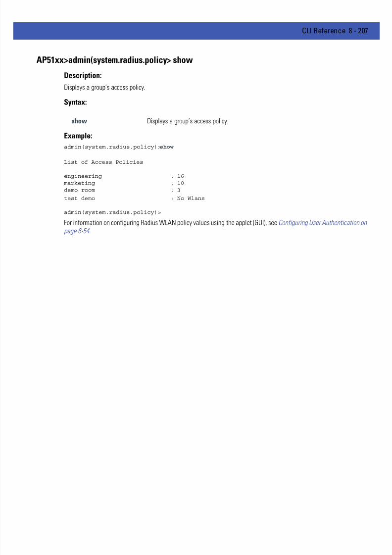
7/18/2019 Motorola AP 5131 Manual
http://slidepdf.com/reader/full/motorola-ap-5131-manual 477/613
CLI Reference 8 - 207
AP51xx>admin(system.radius.policy> show
Description:
Displays a group’s access policy.
Syntax:
Example:
admin(system.radius.policy)>show
List of Access Policies
engineering : 16marketing : 10demo room : 3
test demo : No Wlans
admin(system.radius.policy)>
For information on configuring Radius WLAN policy values using the applet (GUI), see Configuring User Authentication onpage 6-54
show Displays a group’s access policy.
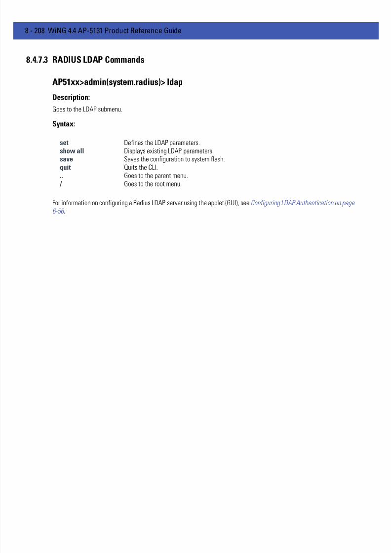
7/18/2019 Motorola AP 5131 Manual
http://slidepdf.com/reader/full/motorola-ap-5131-manual 478/613
8 - 208 WiNG 4.4 AP-5131 Product Reference Guide
8.4.7.3 RADIUS LDAP Commands
AP51xx>admin(system.radius)> ldap
Description:Goes to the LDAP submenu.
Syntax:
For information on configuring a Radius LDAP server using the applet (GUI), see Configuring LDAP Authentication on page6-56 .
set Defines the LDAP parameters.show all Displays existing LDAP parameters.save Saves the configuration to system flash.quit Quits the CLI... Goes to the parent menu.
/ Goes to the root menu.

7/18/2019 Motorola AP 5131 Manual
http://slidepdf.com/reader/full/motorola-ap-5131-manual 479/613
CLI Reference 8 - 209
AP51xx>admin(system.radius.ldap)> set
Description:
Defines the LDAP parameters.
Syntax:
Example:
admin(system.radius.ldap)>set ipadr 157.235.121.12
admin(system.radius.ldap)>set port 203.21.37.18
admin(system.radius.ldap)>set binddn 123
admin(system.radius.ldap)>set basedn 203.21.37.19
admin(system.radius.ldap)>set passwd mudskipper
admin(system.radius.ldap)>set login muddy
admin(system.radius.ldap)>set pass_attr 123
admin(system.radius.ldap)>set groupname 0.0.0.0
admin(system.radius.ldap)>set filter 123
admin(system.radius.ldap)>set membership radiusGroupName
admin(system.radius.ldap)>
For information on configuring a Radius LDAP server using the applet (GUI), see Configuring LDAP Authentication on page6-56 .
set Defines the LDAP parameters.ipadr Sets LDAP IP address.port Sets LDAP server port.binddn Sets LDAP bind distinguished name.basedn Sets LDAP base distinguished name.passwd Sets LDAP server password.login Sets LDAP login attribute.pass_attr Sets LDAP password attribute.groupname Sets LDAP group name attribute.
filter Sets LDAP group membership filter.membership Sets LDAP group membership attribute.
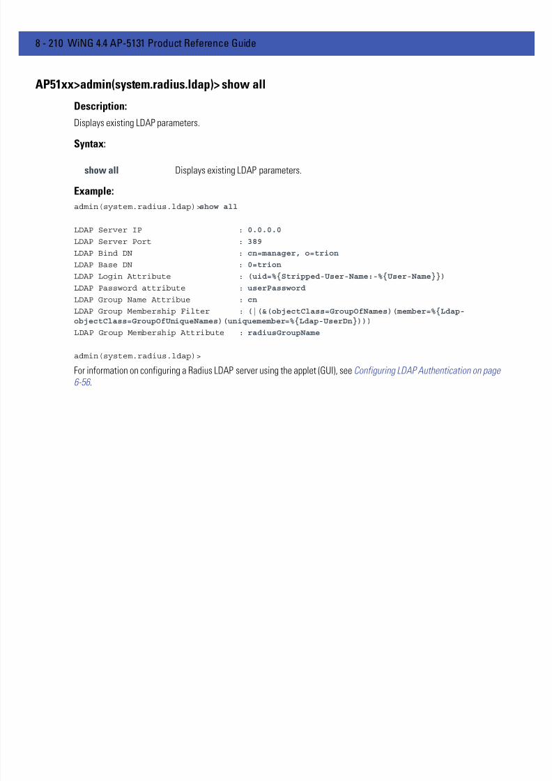
7/18/2019 Motorola AP 5131 Manual
http://slidepdf.com/reader/full/motorola-ap-5131-manual 480/613
8 - 210 WiNG 4.4 AP-5131 Product Reference Guide
AP51xx>admin(system.radius.ldap)> show all
Description:
Displays existing LDAP parameters.
Syntax:
Example:
admin(system.radius.ldap)>show all
LDAP Server IP : 0.0.0.0
LDAP Server Port : 389
LDAP Bind DN : cn=manager, o=trion
LDAP Base DN : 0=trion
LDAP Login Attribute : (uid=%{Stripped-User-Name:-%{User-Name}})
LDAP Password attribute : userPassword
LDAP Group Name Attribue : cn
LDAP Group Membership Filter : (|(&(objectClass=GroupOfNames)(member=%{Ldap-objectClass=GroupOfUniqueNames)(uniquemember=%{Ldap-UserDn})))
LDAP Group Membership Attribute : radiusGroupName
admin(system.radius.ldap)>
For information on configuring a Radius LDAP server using the applet (GUI), see Configuring LDAP Authentication on page6-56 .
show all Displays existing LDAP parameters.
7/18/2019 Motorola AP 5131 Manual
http://slidepdf.com/reader/full/motorola-ap-5131-manual 481/613
CLI Reference 8 - 211
8.4.7.4 RADIUS Proxy Commands
AP51xx>admin(system.radius)> proxy
Description:Goes to the Radius proxy server submenu.
Syntax:
For information on configuring Radius proxy server values using the applet (GUI), see Configuring a Proxy Radius Server onpage 6-58 .
add Adds a proxy realm.delete Deletes a proxy realm.clearall Removes all proxy server records.set Sets proxy server parameters.show Displays current Radius proxy server parameters.save Saves the configuration to system flash.
quit Quits the CLI... Goes to the parent menu.
/ Goes to the root menu.

7/18/2019 Motorola AP 5131 Manual
http://slidepdf.com/reader/full/motorola-ap-5131-manual 482/613
8 - 212 WiNG 4.4 AP-5131 Product Reference Guide
AP51xx>admin(system.radius.proxy)> add
Description:
Adds a proxy.
Syntax:
Example:
admin(system.radius.proxy)>add lancelot 157.235.241.22 1812 muddy
admin(system.radius.proxy)>
For information on configuring Radius proxy server values using the applet (GUI), see Configuring a Proxy Radius Server onpage 6-58 .
add Adds a proxy realm.name <name> Realm name.ip1 <ip1> Authentication server IP address.port <port> Authentication server port.sec <sec> Shared secret password.
7/18/2019 Motorola AP 5131 Manual
http://slidepdf.com/reader/full/motorola-ap-5131-manual 483/613
CLI Reference 8 - 213
AP51xx>admin(system.radius.proxy)> delete
Description:
Adds a proxy.
Syntax:
Example:
admin(system.radius.proxy)>delete lancelot
admin(system.radius.proxy)>
For information on configuring Radius proxy server values using the applet (GUI), see Configuring a Proxy Radius Server onpage 6-58 .
delete <name> Deletes a realm name.

7/18/2019 Motorola AP 5131 Manual
http://slidepdf.com/reader/full/motorola-ap-5131-manual 484/613
8 - 214 WiNG 4.4 AP-5131 Product Reference Guide
AP51xx>admin(system.radius.proxy)> clearall
Description:
Removes all proxy server records from the system.
Syntax:
Example:
admin(system.radius.proxy)>clearall
admin(system.radius.proxy)>
For information on configuring Radius proxy server values using the applet (GUI), see Configuring a Proxy Radius Server onpage 6-58 .
clearall Removes all proxy server records from the system.
7/18/2019 Motorola AP 5131 Manual
http://slidepdf.com/reader/full/motorola-ap-5131-manual 485/613
CLI Reference 8 - 215
AP51xx>admin(system.radius.proxy)> set
Description:
Sets Radius proxy server parameters.
Syntax:
Example:
admin(system.radius.proxy)>set delay 10
admin(system.radius.proxy)>set count 5
admin(system.radius.proxy)>
For information on configuring Radius proxy server values using the applet (GUI), see Configuring a Proxy Radius Server onpage 6-58 .
set Sets Radius proxy server parameters.delay Defines retry delay time (in seconds) for the proxy server.count Defines retry count value for the proxy server.
7/18/2019 Motorola AP 5131 Manual
http://slidepdf.com/reader/full/motorola-ap-5131-manual 486/613
8 - 216 WiNG 4.4 AP-5131 Product Reference Guide
8.4.7.5 RADIUS Client Commands
AP51xx>admin(system.radius)> client
Description:Goes to the Radius client submenu.
Syntax:
For information on configuring Radius client values using the applet (GUI), see Configuring the Radius Server on page 6-54 .
add Adds a Radius client to list of available clients.delete Deletes a Radius client from list of available clients.show Displays a list of configured clients.save Saves the configuration to system flash.quit Quits the CLI... Goes to the parent menu.
/ Goes to the root menu.

7/18/2019 Motorola AP 5131 Manual
http://slidepdf.com/reader/full/motorola-ap-5131-manual 487/613
CLI Reference 8 - 217
AP51xx>admin(system.radius.client> add
Description:
Adds a Radius client to those available to the Radius server.
Syntax:
Example:
admin(system.radius.client)>add 157.235.132.11 255.255.255.225 muddy
admin(system.radius.client)>
For information on configuring Radius client values using the applet (GUI), see Configuring the Radius Server on page 6-54
add Adds a proxy.ip <ip> Client’s IP address.mask <ip1> Network mask address of the client.secret <sec> Shared secret password.
7/18/2019 Motorola AP 5131 Manual
http://slidepdf.com/reader/full/motorola-ap-5131-manual 488/613
8 - 218 WiNG 4.4 AP-5131 Product Reference Guide
AP51xx>admin(system.radius.client> delete
Description:
Removes a specified Radius client from those available to the Radius server.
Syntax:
Example:
admin(system.radius.client)>delete 157.235.132.11
admin(system.radius.client)>
For information on configuring Radius client values using the applet (GUI), see Configuring the Radius Server on page 6-54 .
delete ip Removes a specified Radius client from those available to the Radius server

7/18/2019 Motorola AP 5131 Manual
http://slidepdf.com/reader/full/motorola-ap-5131-manual 489/613
CLI Reference 8 - 219
AP51xx>admin(system.radius.client> show
Description:
Displays a list of configured Radius clients.
Syntax:
Example:
admin(system.radius.client)>show
----------------------------------------------------------------------------Idx Subnet/Host Netmask SharedSecret----------------------------------------------------------------------------1 157.235.132.11 255.255.255.225 *****
admin(system.radius.client)>For information on configuring Radius client values using the applet (GUI), see Configuring the Radius Server on page 6-54
show Removes a specified Radius client from those available to the Radius server.

7/18/2019 Motorola AP 5131 Manual
http://slidepdf.com/reader/full/motorola-ap-5131-manual 490/613
8 - 220 WiNG 4.4 AP-5131 Product Reference Guide
8.4.8 System Network Time Protocol (NTP) Commands
AP51xx>admin(system)> ntp
Description:Displays the NTP menu. The correct network time is required for numerous functions to be configured accurately on theAP-51x1.
Syntax:
For information on configuring NTP using the applet (GUI), see Configuring Network Time Protocol (NTP) on page 4-33 .
show Shows NTP parameters settings.date-zone Show date, time and time zone.zone-list Displays list of time zones.set Sets NTP parameters... Goes to the parent menu.
/ Goes to the root menu.save Saves the configuration to system flash.quit Quits the CLI.

7/18/2019 Motorola AP 5131 Manual
http://slidepdf.com/reader/full/motorola-ap-5131-manual 491/613
CLI Reference 8 - 221
AP51xx>admin(system.ntp)> show
Description:
Displays the NTP server configuration.
Syntax:
Example:
admin(system.ntp)>show
current time (UTC) : 2006-07-31 14:35:20
Time Zone:
ntp mode : enable
preferred Time server ip : 203.21.37.18
preferred Time server port : 123
first alternate server ip : 203.21.37.19
first alternate server port : 123
second alternate server ip : 0.0.0.0
second alternate server port : 123
synchronization interval : 15 minutes
For information on configuring NTP using the applet (GUI), see Configuring Network Time Protocol (NTP) on page 4-33 .
show Shows all NTP server settings.
7/18/2019 Motorola AP 5131 Manual
http://slidepdf.com/reader/full/motorola-ap-5131-manual 492/613
8 - 222 WiNG 4.4 AP-5131 Product Reference Guide
AP51xx>admin(system.ntp)> date-zone
Description:
Show date, time and time zone.
Syntax:
Example:
admin(system.ntp)>date-zone
Date/Time : Sat 1970-Jan-03 20:06:22 +0000 UTC
Time Zone :
For information on configuring NTP using the applet (GUI), see Configuring Network Time Protocol (NTP) on page 4-33 .
date-zone Show date, time and time zone.

7/18/2019 Motorola AP 5131 Manual
http://slidepdf.com/reader/full/motorola-ap-5131-manual 493/613
CLI Reference 8 - 223
AP51xx>admin(system.ntp)> zone-list
Description:
Displays an extensive list of time zones for countries around the world.
Syntax:
Example:
admin(system.ntp)> zone-list
For information on configuring NTP using the applet (GUI), see Configuring Network Time Protocol (NTP) on page 4-33 .
zone-list Displays list of time zone indexes for every known zone.

7/18/2019 Motorola AP 5131 Manual
http://slidepdf.com/reader/full/motorola-ap-5131-manual 494/613
8 - 224 WiNG 4.4 AP-5131 Product Reference Guide
AP51xx>admin(system.ntp)> set
Description:
Sets NTP parameters for AP-51x1 clock synchronization.
Syntax:
Example:
admin(system.ntp)>set mode enable
admin(system.ntp)>set server 1 203.21.37.18
admin(system.ntp)>set port 1 123
admin(system.ntp)>set intrvl 15
admin(system.ntp)>set zone 1
For information on configuring NTP using the applet (GUI), see Configuring Network Time Protocol (NTP) on page 4-33 .
set mode <ntp-mode>
Enables or disables NTP.
server <idx><ip>
Sets the NTP sever IP address.
port <idx><port>
Defines the port number.
intrvl <period>
Defines the clock synchronization interval used between theAP-51x1 and the NTP server in minutes (15 - 65535).
time <time> Sets the current system time. [yyyy] - year, [mm] - month, [dd] - day
of the month, [hh] - hour of the day, [mm] - minute, [ss] second, [zone-idx] Index of the zone.
zone <zone> Defines the time zone (by index) for the target country.
7/18/2019 Motorola AP 5131 Manual
http://slidepdf.com/reader/full/motorola-ap-5131-manual 495/613
CLI Reference 8 - 225
8.4.9 System Log Commands
AP51xx>admin(system)> logs
Description:Displays the AP-51x1 log submenu. Logging options include:
Syntax:
show Shows logging options.set Sets log options and parameters.view Views system log.delete Deletes the system log.send Sends log to the designated FTP Server... Goes to the parent menu.
/ Goes to the root menu.save Saves configuration to system flash.quit Quits the CLI.

7/18/2019 Motorola AP 5131 Manual
http://slidepdf.com/reader/full/motorola-ap-5131-manual 496/613
8 - 226 WiNG 4.4 AP-5131 Product Reference Guide
AP51xx>admin(system.logs)> show
Description:
Displays the current AP-51x1 logging settings.
Syntax:
Example:
admin(system.logs)>show
log level : L6 Info
syslog server logging : enable
syslog server ip address : 192.168.0.102
For information on configuring logging settings using the applet (GUI), see Logging Configuration on page 4-37 .
show Displays the current access point logging configuration.
7/18/2019 Motorola AP 5131 Manual
http://slidepdf.com/reader/full/motorola-ap-5131-manual 497/613
CLI Reference 8 - 227
AP51xx>admin(system.logs)> set
Description:
Sets log options and parameters.
Syntax:
admin(system.logs)>set mode enable
admin(system.logs)>set level L4
admin(system.logs)>set ipadr 157.235.112.11
For information on configuring logging settings using the applet (GUI), see Logging Configuration on page 4-37 .
set level <level> Sets the level of the events that will be logged. All events with a level at or above<level> (L0-L7) will be saved to the system log.L0:EmergencyL1:AlertL2:CriticalL3:ErrorsL4:WarningL5:NoticeL6:Info (default setting)
L7:Debug
mode <mode> Enables or disables syslog server logging.
ipadr <ip> Sets the external syslog server IP address to <ip> (a.b.c.d).

7/18/2019 Motorola AP 5131 Manual
http://slidepdf.com/reader/full/motorola-ap-5131-manual 498/613
8 - 228 WiNG 4.4 AP-5131 Product Reference Guide
AP51xx>admin(system.logs)> view
Description:
Displays the AP-51x1 system log file.
Syntax:
Example:
admin(system.logs)>view
Jan 7 16:14:00 (none) syslogd 1.4.1: restart (remote reception).
Jan 7 16:14:10 (none) klogd: :ps log:fc: queue maintenance
Jan 7 16:14:41 (none) klogd: :ps log:fc: queue maintenance
Jan 7 16:15:43 (none) last message repeated 2 times
Jan 7 16:16:01 (none) CC: 4:16pm up 6 days, 16:16, load average: 0.00, 0.01,
0.00
Jan 7 16:16:01 (none) CC: Mem: 62384 32520 29864
0 0
Jan 7 16:16:01 (none) CC: 0000077e 0012e95b 0000d843 00000000 00000003 0000121
e 00000000 00000000 0037ebf7 000034dc 00000000 00000000 00000000
Jan 7 16:16:13 (none) klogd: :ps log:fc: queue maintenance
Jan 7 16:16:44 (none) klogd: :ps log:fc: queue maintenance
Jan 7 16:17:15 (none) klogd: :ps log:fc: queue maintenance
Jan 7 16:17:15 (none) klogd: :ps log:fc: queue maintenance
For information on configuring logging settings using the applet (GUI), see Logging Configuration on page 4-37 .
view Displays the entire AP-51x1 system log file.

7/18/2019 Motorola AP 5131 Manual
http://slidepdf.com/reader/full/motorola-ap-5131-manual 499/613
CLI Reference 8 - 229
AP51xx>admin(system.logs)> delete
Description:
Deletes the log files.
Syntax:
Example:
admin(system.logs)>delete
For information on configuring logging settings using the applet (GUI), see Logging Configuration on page 4-37 .
delete Deletes the AP-51x1 system log file.
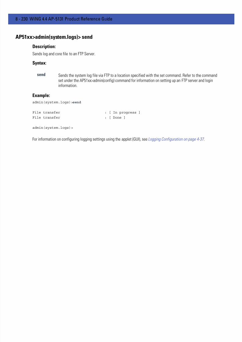
7/18/2019 Motorola AP 5131 Manual
http://slidepdf.com/reader/full/motorola-ap-5131-manual 500/613
8 - 230 WiNG 4.4 AP-5131 Product Reference Guide
AP51xx>admin(system.logs)> send
Description:
Sends log and core file to an FTP Server.
Syntax:
Example:
admin(system.logs)>send
File transfer : [ In progress ]
File transfer : [ Done ]
admin(system.logs)>
For information on configuring logging settings using the applet (GUI), see Logging Configuration on page 4-37 .
send Sends the system log file via FTP to a location specified with the set command. Refer to the commandset under the AP51xx>admin(config) command for information on setting up an FTP server and logininformation.

7/18/2019 Motorola AP 5131 Manual
http://slidepdf.com/reader/full/motorola-ap-5131-manual 501/613
CLI Reference 8 - 231
8.4.10 System Configuration-Update Commands
AP51xx>admin(system)>config
Description:Displays the AP-51x1 configuration update submenu.
Syntax:
default Restores the default AP-51x1 configuration.partial Restores a partial default AP-51x1 configuration.show Shows import/export parameters.set Sets import/export AP-51x1 configuration parameters.export Exports AP-51x1 configuration to a designated system.import Imports configuration to the access point.
.. Goes to the parent menu. / Goes to the root menu.save Saves the configuration to AP-51x1 system flash.quit Quits the CLI.

7/18/2019 Motorola AP 5131 Manual
http://slidepdf.com/reader/full/motorola-ap-5131-manual 502/613
8 - 232 WiNG 4.4 AP-5131 Product Reference Guide
AP51xx>admin(system.config)> default
Description:
Restores the full AP-51x1 factory default configuration.
Syntax:
Example:
admin(system.config)>default
Are you sure you want to default the configuration? <yes/no>:
For information on importing/exporting access point configurations using the applet (GUI), see Importing/ExportingConfigurations on page 4-39 .
default Restores the AP-51x1 to the original (factory) configuration.

7/18/2019 Motorola AP 5131 Manual
http://slidepdf.com/reader/full/motorola-ap-5131-manual 503/613
CLI Reference 8 - 233
AP51xx>admin(system.config)> partial
Description:
Restores a partial factory default configuration. The AP-51x1’s LAN, WAN and SNMP settings are uneffected by the partial
restore.
Syntax:
Example:
admin(system.config)>partial
Are you sure you want to partially default AP-51xx? <yes/no>:
For information on importing/exporting access point configurations using the applet (GUI), see Importing/ExportingConfigurations on page 4-39 .
default Restores a partial access point configuration.

7/18/2019 Motorola AP 5131 Manual
http://slidepdf.com/reader/full/motorola-ap-5131-manual 504/613
8 - 234 WiNG 4.4 AP-5131 Product Reference Guide
AP51xx>admin(system.config)> show
Description:
Displays import/export parameters for the AP-51x1 configuration file.
Syntax:
Example:
admin(system.config)>show
cfg filename : cfg.txt
cfg filepath :
ftp/tftp server ip address : 192.168.0.101
ftp user name : myadmin
ftp password : ********
For information on importing/exporting access point configurations using the applet (GUI), seeImporting/Exporting Configurations on page 4-39 .
show Shows all import/export parameters.

7/18/2019 Motorola AP 5131 Manual
http://slidepdf.com/reader/full/motorola-ap-5131-manual 505/613
CLI Reference 8 - 235
AP51xx>admin(system.config)> set
Description:
Sets the import/export parameters.
Syntax:
Example:
admin(system.config)>set server 192.168.22.12
admin(system.config)>set user myadmin
admin(system.config>set passwd georges
admin(system.config)>show
cfg filename : cfg.txt
cfg filepath :
ftp/tftp server ip address : 192.168.22.12
ftp user name : myadmin
ftp password : *******
For information on importing/exporting access point configurations using the applet (GUI), seeImporting/Exporting Configurations on page 4-39 .
set file <filename> Sets the configuration file name (1 to 39 characters inlength).
path <path> Defines the path used for the configuration file upload.server <ipaddress> Sets the FTP/TFTP server IP address.user <username> Sets the FTP user name (1 to 39 characters in length).passwd <pswd> Sets the FTP password (1 to 39 characters in length).
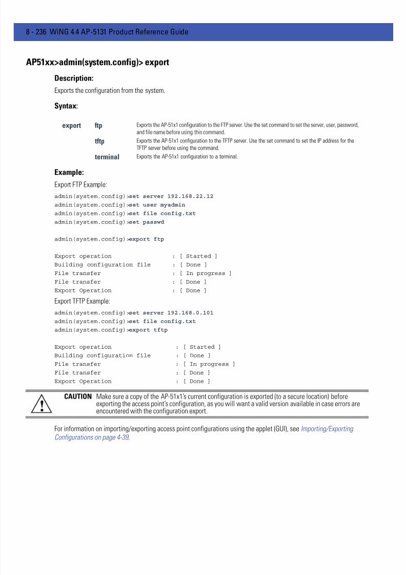
7/18/2019 Motorola AP 5131 Manual
http://slidepdf.com/reader/full/motorola-ap-5131-manual 506/613
8 - 236 WiNG 4.4 AP-5131 Product Reference Guide
AP51xx>admin(system.config)> export
Description:
Exports the configuration from the system.
Syntax:
Example:
Export FTP Example:
admin(system.config)>set server 192.168.22.12
admin(system.config)>set user myadmin
admin(system.config)>set file config.txt
admin(system.config)>set passwd
admin(system.config)>export ftp
Export operation : [ Started ]
Building configuration file : [ Done ]
File transfer : [ In progress ]
File transfer : [ Done ]
Export Operation : [ Done ]
Export TFTP Example:admin(system.config)>set server 192.168.0.101
admin(system.config)>set file config.txt
admin(system.config)>export tftp
Export operation : [ Started ]
Building configuration file : [ Done ]
File transfer : [ In progress ]
File transfer : [ Done ]
Export Operation : [ Done ]
For information on importing/exporting access point configurations using the applet (GUI), see Importing/ExportingConfigurations on page 4-39 .
export ftp Exports the AP-51x1 configuration to the FTP server. Use the set command to set the server, user, password,
and file name before using this command.
tftp Exports the AP-51x1 configuration to the TFTP server. Use the set command to set the IP address for the
TFTP server before using the command.
terminal Exports the AP-51x1 configuration to a terminal.
CAUTION Make sure a copy of the AP-51x1’s current configuration is exported (to a secure location) before
exporting the access point’s configuration, as you will want a valid version available in case errors areencountered with the configuration export.!

7/18/2019 Motorola AP 5131 Manual
http://slidepdf.com/reader/full/motorola-ap-5131-manual 507/613
CLI Reference 8 - 237
AP51xx>admin(system.config)> import
Description:
Imports the AP-51x1 configuration to the access point. Errors could display as a result of invaid configuration parameters.
Correct the sepcified lines and import the file again until the import operation is error free.
Syntax:
Example:
Import FTP Example
admin(system.config>set server 192.168.22.12
admin(system.config>set user myadmin
admin(system.config)>set file config.txt
admin(system.config)>set passwd mysecret
admin(system.config)>import ftp
Import operation : [ Started ]
File transfer : [ In progress ]
File transfer : [ Done ]
Import operation : [ Done ]
Import TFTP Example
admin(system.config)>set server 192.168.0.101
admin(system.config)>set file config.txt
admin(system.config)>import tftp
Import operation : [ Started ]
File transfer : [ In progress ]
File transfer : [ Done ]
Import operation : [ Done ]
For information on importing/exporting access point configurations using the applet (GUI), see Importing/ExportingConfigurations on page 4-39 .
import ftp Imports the AP-51x1 configuration file from the FTP server. Use the set command to set the server,user, password, and file.
tftp Imports the AP-51x1 configuration from the TFTP server. Use the set command to set the server andfile.
CAUTION A single-radio model access point cannot import/export its configuration to a dual-radio model accesspoint. In turn, a dual-radio model access point cannot import/export its configuration to a single-radioaccess point.
CAUTION Motorola Solutions discourages importing a 1.0 baseline configuration file to a 1.1 version accesspoint. Similarly, a 1.1 baseline configuration file should not be imported to a 1.0 version access point.Importing configurations between different version access point’s results in broken configurations,since new features added to the 1.1 version access point cannot be supported in a 1.0 version accesspoint.
!
!
7/18/2019 Motorola AP 5131 Manual
http://slidepdf.com/reader/full/motorola-ap-5131-manual 508/613
8 - 238 WiNG 4.4 AP-5131 Product Reference Guide
8.4.11 Firmware Update Commands
AP51xx>admin(system)>fw-update
Description:Displays the firmware update submenu. The items available under this command are shown below.
NOTE The access point must complete the reboot process to successfully update the device firmware,regardless of whether the reboot is conducted uing the GUI or CLI interfaces.
show Displays the current AP-51x1 firmware update settings.set Defines the AP-51x1 firmware update parameters.update Executes the firmware update... Goes to the parent menu.
/ Goes to the root menu.save Saves the current configuration to the AP-51x1 system flash.quit Quits the CLI and exits the current session.

7/18/2019 Motorola AP 5131 Manual
http://slidepdf.com/reader/full/motorola-ap-5131-manual 509/613
CLI Reference 8 - 239
AP51xx>admin(system.fw-update)>show
Description:
Displays the current AP-51x1 firmware update settings.
Syntax:
Example:
admin(system.fw-update)>show
automatic firmware upgrade : enableautomatic config upgrade : enable
firmware filename : APFW.bin
firmware path : /tftpboot/ftp/tftp server ip address : 168.197.2.2ftp user name : jsmithftp password : *******
For information on updating access point device firmware using the applet (GUI), see Updating Device Firmware on page4-44 .
show Shows the current system firmware update settings for the AP-51x1.

7/18/2019 Motorola AP 5131 Manual
http://slidepdf.com/reader/full/motorola-ap-5131-manual 510/613
8 - 240 WiNG 4.4 AP-5131 Product Reference Guide
AP51xx>admin(system.fw-update)>set
Description:
Defines AP-51x1 firmware update settings and user permissions.
Syntax:
admin(system.fw-update)>set fw-auto enable
admin(system.fw-update)>set cfg-auto enable
admin(system.fw-update)>set file 2.0.0.0-29D
admin(system.fw-update)>set path c:/fw
admin(system.fw-update)>set server 157.235.111.22
admin(system.fw-update)>set user mudskipper
admin(system.fw-update)>set passwd muddy
For information on updating access point device firmware using the applet (GUI), see Updating Device Firmware on page4-44 .
set fw-auto <mode> When enabled, updates device firmware each time the firmware versionsare found to be different between the AP-51x1 and the specified firmwareon the remote system.
cfg-auto <mode> When enabled, updates device configuration file each time the confif fileversions are found to be different between the AP-51x1 and the specifiedLAN or WAN interface.
file <name> Defines the firmware file name (1 to 39 characters).
path <path> Specifies a path for the file (1 to 39 characters)..
server <ip> The IP address for the FTP/TFTP server used for the firmware and/or configfile update.
user <name> Specifies a username for FTP server login (1 to 39 characters)..
passwd <password> Specifies a password for FTP server login (1 to 39 characters).. Default ismotorola.

7/18/2019 Motorola AP 5131 Manual
http://slidepdf.com/reader/full/motorola-ap-5131-manual 511/613
CLI Reference 8 - 241
AP51xx>admin(system.fw-update)>update
Description:
Executes the AP-51x1 firmware update over the WAN or LAN port using either ftp or tftp.
Syntax:
admin(system.fw-update)>update ftp
For information on updating access point device firmware using the applet (GUI), see Updating Device Firmware on page4-44 .
update <mode><iface> Defines the ftp ot tftp mode used to conduct the firmware update. Specifies whether theupdate is executed over the AP-51x1’s WAN, LAN1 or LAN2 interface <iface>.
NOTE The access point must complete the reboot process to successfully update the device firmware,regardless of whether the reboot is conducted uing the GUI or CLI interfaces.
7/18/2019 Motorola AP 5131 Manual
http://slidepdf.com/reader/full/motorola-ap-5131-manual 512/613
8 - 242 WiNG 4.4 AP-5131 Product Reference Guide
8.5 Statistics Commands
AP51xx>admin(stats)
Description:Displays the AP-51x1 statistics submenu. The items available under this command are:
show Displays AP-51x1 WLAN, MU, LAN and WAN statistics.send-cfg-ap Sends a config file to another access point within the known AP table.send-cfg-all Sends a config file to all access points within the known AP table.clear Clears all statistic counters to zero.flash-all-leds Starts and stops the flashing of all AP-51x1 LEDs.echo Defines the parameters for pinging a designated station.ping Iniates a ping test... Moves to the parent menu.
/ Goes to the root menu.save Saves the current configuration to system flash.quit Quits the CLI.

7/18/2019 Motorola AP 5131 Manual
http://slidepdf.com/reader/full/motorola-ap-5131-manual 513/613
CLI Reference 8 - 243
AP51xx>admin(stats)> show
Description:
Displays AP-51x1 system information.
Syntax:
For information on displaying WAN port statistics using the applet (GUI), see Viewing WAN Statistics on page 7-3 .
For information on displaying LAN port statistics using the applet (GUI), see Viewing LAN Statistics on page 7-6 .
For information on displaying Wireless statistics using the applet (GUI), see Viewing Wireless Statistics on page 7-11.
For information on displaying individual WLAN statistics using the applet (GUI), see Viewing WLAN Statistics on page 712 .
For information on displaying Radio statistics using the applet (GUI), see Viewing Radio Statistics Summary on page 7-16
For information on displaying MU statistics using the applet (GUI), see Viewing MU Statistics Summary on page 7-21.
For information on displaying Mesh statistics using the applet (GUI), see Viewing the Mesh Statistics Summary on page7-26 .
For information on displaying Known AP statistics using the applet (GUI), see Viewing Known Access Point Statistics onpage 7-28 .
show wan Displays stats for the AP-51x1 WAN port.lan Displays stats for the AP-51x1 LAN portstp Displays LAN Spanning Tree Statuswlan Displays WLAN status and statistics summary.s-wlan Displays status and statistics for an individual WLANradio Displays a radio statistics transmit and receive summary.s-radio Displays radio statistics for a single radioretry-hgram Displays a radio’s retry histogram statistics.mu Displays all mobile unit (MU) status.
s-mu Displays status and statistics for an individual MU.auth-mu Displays single MU Authentication statistics.wlap Displays Wireless Bridge Statistics statistics summary.s-wlap Displays single Wirless Bridge statistics.known-ap Displays a Known AP summary.
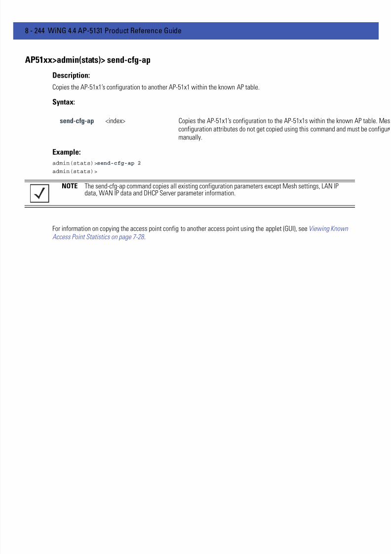
7/18/2019 Motorola AP 5131 Manual
http://slidepdf.com/reader/full/motorola-ap-5131-manual 514/613
8 - 244 WiNG 4.4 AP-5131 Product Reference Guide
AP51xx>admin(stats)> send-cfg-ap
Description:
Copies the AP-51x1’s configuration to another AP-51x1 within the known AP table.
Syntax:
Example:
admin(stats)>send-cfg-ap 2
admin(stats)>
For information on copying the access point config to another access point using the applet (GUI), see Viewing KnownAccess Point Statistics on page 7-28 .
send-cfg-ap <index> Copies the AP-51x1’s configuration to the AP-51x1s within the known AP taconfiguration attributes do not get copied using this command and must bemanually.
NOTE The send-cfg-ap command copies all existing configuration parameters except Mesh settings, LAN IP
data, WAN IP data and DHCP Server parameter information.

7/18/2019 Motorola AP 5131 Manual
http://slidepdf.com/reader/full/motorola-ap-5131-manual 515/613
CLI Reference 8 - 245
AP51xx>admin(stats)> send-cfg-all
Description:
Copies the AP-51x1’s configuration to all of the AP-51x1s within the known AP table.
Syntax:
Example:
admin(stats)>send-cfg-all
admin(stats)>
For information on copying the access point config to another access point using the applet (GUI), see Viewing KnownAccess Point Statistics on page 7-28 .
send-cfg-all Copies the AP-51x1’s configuration to all of the AP-51x1s within the known AP table.
NOTE The send-cfg-all command copies all existing configuration parameters except Mesh settings, LAN IPdata, WAN IP data and DHCP Server parameter information.

7/18/2019 Motorola AP 5131 Manual
http://slidepdf.com/reader/full/motorola-ap-5131-manual 516/613
8 - 246 WiNG 4.4 AP-5131 Product Reference Guide
AP51xx>admin(stats)> clear
Description:
Clears the specified statistics counters to zero to begin new data calculations.
Syntax:
clear wan Clears WAN statistics counters.
lan Clears LAN statistics counters for specified LAN index (either clear lan 1 or clear lan 2).
all-rf Clears all RF data.
all-wlan Clears all WLAN summary information.
wlan Clears individual WLAN statistic counters.
all-radio Clears AP-51x1 radio summary information.
radio1 Clears statistics counters specific to radio1.
radio2 Clears statistics counters specific to radio2.
all-mu Clears all MU statistic counters.
mu Clears MU statistics counters.
known-ap Clears Known AP statistic counters.

7/18/2019 Motorola AP 5131 Manual
http://slidepdf.com/reader/full/motorola-ap-5131-manual 517/613
CLI Reference 8 - 247
AP51xx>admin(stats)> flash-all-leds
Description:
Starts and stops the illumination of a specified access point’s LEDs.
Syntax:
Example:
admin(stats)>
admin(stats)>flash-all-leds 1 start
Password ********
admin(stats)>flash-all-leds 1 stop
admin(stats)>
For information on flashing access point LEDs using the applet (GUI), see Viewing Known Access Point Statistics on page7-28 .
flash-all-leds <index> Defines the Known AP index number of the target AP to flash.<stop/start> Begins or terminates the flash activity.

7/18/2019 Motorola AP 5131 Manual
http://slidepdf.com/reader/full/motorola-ap-5131-manual 518/613
8 - 248 WiNG 4.4 AP-5131 Product Reference Guide
8.5.1 Statistics Echo Commands
AP51xx>admin(stats)> echo
Description:Defines the echo test values used to conduct a ping test to an associated MU.
Syntax:
For information on MU Echo and Ping tests using the applet (GUI), see Pinging Individual MUs on page 7-24 .
show Shows the Mobile Unit Statistics Summary.list Defines echo test parameters and result.set Determines echo test packet data.start Begins echoing the defined station... Goes to parent menu.
/ Goes to root menu.
quit Quits CLI session.

7/18/2019 Motorola AP 5131 Manual
http://slidepdf.com/reader/full/motorola-ap-5131-manual 519/613
CLI Reference 8 - 249
AP51xx>admin.stats.echo)> show
Description:
Shows Mobile Unit Statistics Summary.
Syntax:
Example:
admin(stats.echo)>show
----------------------------------------------------------------------------Idx IP Address MAC Address WLAN Radio T-put ABS Retries----------------------------------------------------------------------------1 192.168.2.0 00:A0F8:72:57:83 demo 11a
For information on MU Echo and Ping tests using the applet (GUI), see Pinging Individual MUs on page 7-24 .
show Shows Mobile Unit Statistics Summary.

7/18/2019 Motorola AP 5131 Manual
http://slidepdf.com/reader/full/motorola-ap-5131-manual 520/613
8 - 250 WiNG 4.4 AP-5131 Product Reference Guide
AP51xx>admin(stats.echo)> list
Description:
Lists echo test parameters and results.
Syntax:
Example:
admin(stats.echo)>list
Station Address : 00A0F8213434
Number of Pings : 10
Packet Length : 10
Packet Data (in HEX) : 55
admin(stats.echo)>
For information on MU Echo and Ping tests using the applet (GUI), see Pinging Individual MUs on page 7-24 .
list Lists echo test parameters and results.

7/18/2019 Motorola AP 5131 Manual
http://slidepdf.com/reader/full/motorola-ap-5131-manual 521/613
CLI Reference 8 - 251
AP51xx>admin(stats.echo)>set
Description:
Defines the parameters of the echo test.
Syntax:
For information on MU Echo and Ping tests using the applet (GUI), see Pinging Individual MUs on page 7-24 .
set station <mac> Defines MU target MAC address.request <num> Sets number of echo packets to transmit (1-539).length <num> Determines echo packet length in bytes (1-539).data <hex> Defines the particular packet data.

7/18/2019 Motorola AP 5131 Manual
http://slidepdf.com/reader/full/motorola-ap-5131-manual 522/613
8 - 252 WiNG 4.4 AP-5131 Product Reference Guide
AP51xx>admin(stats.echo)> start
Description:
Initiates the echo test.
Syntax:
Example:
admin(stats.echo)>start
admin(stats.echo)>list
Station Address : 00A0F843AABB
Number of Pings : 10
Packet Length : 100Packet Data (in HEX) : 1
Number of MU Responses : 2
For information on MU Echo and Ping tests using the applet (GUI), see Pinging Individual MUs on page 7-24 .
start Initiates the echo test.

7/18/2019 Motorola AP 5131 Manual
http://slidepdf.com/reader/full/motorola-ap-5131-manual 523/613
CLI Reference 8 - 253
8.5.2 Statistics Ping Commands
AP51xx>admin(stats)> ping
Description:Defines the ping test values used to conduct a ping test to an AP with the same ESSID.
Syntax:
For information on Known AP tests using the applet (GUI), see Pinging Individual MUs on page 7-24 .
ping show Shows Known AP Summary details.list Defines ping test packet length.set Determines ping test packet data.start Begins pinging the defined station... Goes to parent menu.
/ Goes to root menu.
quit Quits CLI session.

7/18/2019 Motorola AP 5131 Manual
http://slidepdf.com/reader/full/motorola-ap-5131-manual 524/613
8 - 254 WiNG 4.4 AP-5131 Product Reference Guide
AP51xx>admin(stats.ping)> show
Description:
Shows Known AP Summary Details.
Syntax:
Example:
admin(stats.ping)>show
----------------------------------------------------------------------------Idx IP Address MAC Address MUs KBIOS Unit Name----------------------------------------------------------------------------1 192.168.2.0 00:A0F8:72:57:83 3 0 access point
show Shows Known AP Summary Details.

7/18/2019 Motorola AP 5131 Manual
http://slidepdf.com/reader/full/motorola-ap-5131-manual 525/613
CLI Reference 8 - 255
AP51xx>admin(stats.ping)> list
Description:
Lists ping test parameters and results.
Syntax:
Example:
admin(stats.ping)>list
Station Address : 00A0F8213434
Number of Pings : 10
Packet Length : 10
Packet Data (in HEX) : 55
admin(stats.ping)>
For information on Known AP tests using the applet (GUI), see Pinging Individual MUs on page 7-24 .
list Lists ping test parameters and results.

7/18/2019 Motorola AP 5131 Manual
http://slidepdf.com/reader/full/motorola-ap-5131-manual 526/613
8 - 256 WiNG 4.4 AP-5131 Product Reference Guide
AP51xx>admin(stats.ping)> set
Description:
Defines the parameters of the ping test.
Syntax:
Example:
admin(stats.ping)>set station 00A0F843AABB
admin(stats.ping)>set request 10
admin(stats.ping)>set length 100
admin(stats.ping)>set data 1
admin(stats.ping)>
For information on Known AP tests using the applet (GUI), see Pinging Individual MUs on page 7-24 .
set station Defines the AP target MAC address.request Sets number of ping packets to transmit (1-539).length Determines ping packet length in bytes (1-539).data Defines the particular packet data.

7/18/2019 Motorola AP 5131 Manual
http://slidepdf.com/reader/full/motorola-ap-5131-manual 527/613
CLI Reference 8 - 257
AP51xx>admin(stats.ping)> start
Description:
Initiates the ping test.
Syntax:
Example:
admin(stats.ping)>start
admin(stats.ping)>list
Station Address : 00A0F843AABB
Number of Pings : 10
Packet Length : 100Packet Data (in HEX) : 1
Number of AP Responses : 2
For information on Known AP tests using the applet (GUI), see Pinging Individual MUs on page 7-24 .
start Initiates the ping test.

7/18/2019 Motorola AP 5131 Manual
http://slidepdf.com/reader/full/motorola-ap-5131-manual 528/613
8 - 258 WiNG 4.4 AP-5131 Product Reference Guide

7/18/2019 Motorola AP 5131 Manual
http://slidepdf.com/reader/full/motorola-ap-5131-manual 529/613
CHAPTER 9 CONFIGURING MESH
NETWORKING
9.1 Mesh Networking Overview
An AP-51xx can be configured in two modes to support the new mesh networking functionality. The access point can beset to a client bridge mode and/or a base bridge mode (which accepts connections from client bridges). Base bridge andclient bridge mode can be used at the same time by an individual access point to optimally bridge traffic to other membersof the mesh network and service associated MUs.
An access point in client bridge mode scans to locate other access points using the WLAP client's ESSID. Then it is requiredto go through the association and authentication process to establish wireless connections with the located devices. Thisassociation process is identical to the access point’s current MU association process. Once the association andauthentication process is complete, the wireless client adds the connection as a port on its bridge module. This causes theclient bridge to begin forwarding packets to the base bridge node. The base bridge realizes it is talking to a wireless client
bridge. It then adds that connection as a port on its own bridge module. The two bridges at that point are communicatingusing the Spanning Tree Protocol (STP).
access points configured as both a base and a client bridge function as repeaters to transmit data with associated MUsin their coverage area (client bridge mode) as well as forward traffic to other access points in the mesh network (basebridge mode). The number of access points and their intended function within the mesh network dictate whether theyshould be configured as base bridges, client bridges or both (repeaters).
The spanning tree determines the path to the root and detects if the current connection is part of a network loop withanother connection in the system. Each bridge can be configurable so the administrator can control the spanning tree todefine the root bridge and what the forwarding paths are. Once the spanning tree converges, both access points beginlearning which destinations reside on which side of the network. This allows them to forward traffic intelligently.
After the client bridge establishes at least one wireless connection (if configured to support mobile users), it beginsbeaconing and accepting wireless connections. If configured as both a client bridge and a base bridge, it begin acceptingclient bridge connections. Therefore, the mesh network could connect simultaneously to different networks in a mannerwhereby a network loop is not created and then the connection is not blocked. Once the client bridge establishes at leastone wireless connection, it begins establishing other wireless connections as it finds them available. Thus, the clientbridge is able to establish simultaneous redundant links.
A mesh network must use one of the two access point LANs. If intending to use the access point for mesh networkingsupport, Motorola Solutions recommends configuring at least one WLAN (of the 16 WLANs available) specifically for meshnetworking support.
The client bridge creates up to three connections if it can find base bridges for connection. If the connections are redundant(on the same network), then one connection will be forwarding and the others blocked. However, if each of the connections
7/18/2019 Motorola AP 5131 Manual
http://slidepdf.com/reader/full/motorola-ap-5131-manual 530/613
9 - 2 WiNG 4.4 AP-5131 Product Reference Guide
links to a different wired network, then none are redundant and all are forwarding. Thus, the bridge automatically detectsand disables redundant connections, but leaves non-redundant connections forwarding. This gives the user the freedomto configure their topology in a variety of ways without limitations. This is important when configuring multiple accesspoints for base bridge support in areas like a shipping yard where a large radio coverage area is required. For moreinformation on configuring the access point in respect to specific usage scenarios, see Mesh Network Deployment - QuickSetup on page 9-15 .
If an access point is configured as a base bridge (but not as a client bridge) it operates normally at boot time. The basebridge supports connections made by other client bridges.
The dual-radio model access point affords users better optimization of the mesh networking feature by enabling the accesspoint to transmit to other mesh network members using one independent radio and transmit with associated MUs using
the second independent radio. A single-radio access point has its channel utilization and throughput degraded in a meshnetwork, as the AP’s single radio must process both mesh network traffic with other access points and MU traffic with itsassociated devices.
9.1.1 The AP-51xx Client Bridge Association Process
An access point in client bridge mode performs an active scan to quickly create a table of the access points nearby. Thetable contains the access points matching the ESS of the client bridge AP’s WLAN. The table is used to determine the bestaccess point to connect to (based on signal strength, load and the user's configured preferred connection list).
The association and authentication process is identical to the MU association process. The client access point sends802.11 authentication and association frames to the base access point. The base access point responds as if the client isan actual mobile unit. Depending on the security policy, the two access point’s engage in the normal handshake mechanismto establish keys.
After device association, the two access points are connected and the system can establish the bridge and run thespanning tree algorithm. In the meantime, the access point in client bridge mode continues to scan in the backgroundattempts to establish an association with other access points using the same ESS on the same channel.
The access point in client bridge mode attempts to establish up to 3 simultaneous wireless connections. The second andthird connections are established in the background while the system is running. The first connection needs to beestablished before the system starts bridging traffic.
The dual-radio model access point affords users better optimization of the mesh networking feature by allowing the accesspoint to transmit to other access points (in base or client bridge mode) using one independent radio and transmit with itsassociated MUs using the second independent radio. A single-radio access point has its channel utilization and throughput
NOTE Since each access point can establish up to 3 simultaneous wirelessconnections, some of these connections could be redundant. If this is thecase, the STP algorithm defines which links are the redundant links anddisables those links from forwarding.
CAUTION Only Motorola Solutions AP-5131 or AP-5181 model access points canbe used as base bridges, client bridges or repeaters within an accesspoint supported mesh network. If utilizing a mesh network, MotorolaSolutions recommends considering a dual-radio model to optimizechannel utilization and throughput.
CAUTION An access point is Base Bridge mode logs out whenever a ClientBridge associates to the Base Bridge over the LAN connection. Thisproblem is not experienced over the access point’s WAN connection. Ifthis situation is experienced, log-in to the access point again.

7/18/2019 Motorola AP 5131 Manual
http://slidepdf.com/reader/full/motorola-ap-5131-manual 531/613
Configuring Mesh Networking 9 - 3
degraded in a mesh network, as the access point’s single radio must process both mesh network traffic with other accesspoints and MU traffic with its associated devices.
9.1.1.1 Client Bridge Configuration Process Example
In this example, two access points are described with the following configurations:• AP #1 base bridge
• AP #2 repeater (both a base and client bridge)
In the case of a mesh enabled radio, the client bridge configuration always takes precedence over the base bridgeconfiguration. Therefore, when a radio is configured as a repeater (AP #2), the base bridge configuration takes effect onlyafter the client bridge connection to AP #1 is established. Thus, AP #2 keeps scanning to find the base bridge, form theuplink and start beaconing as a base bridge for downstream client bridge connection. This is by design, as there is noreason to use a partially broken connection with no uplink to a base bridge.
9.1.2 Spanning Tree Protocol (STP) The access point performs mesh networking using STP as defined in the 802.1d standard.
Once device association is complete, the client and base bridge exchange Configuration Bridge Protocol Data Units (BPDUs) to determine the path to the root. STP also determines whether a given port is a redundant connection or not.
9.1.3 Defining the Mesh Topology When a user wants to control how the spanning tree determines client bridge connections, they need to control the meshconfiguration. The user must be able to define one node as the root. Assigning a base bridge the lowest bridge prioritydefines it as the root.
The access point can manipulate the path cost assigned to a bridge connection based on that connection’s RSSI. This
results in the spanning tree selecting the optimal path for forwarding data when redundant paths exist. However, this canbe overridden using the preferred list. When using the preferred list, the user enters a priority for each bridge, resulting inthe selection of the forwarding link.
Limit the wireless client’s connections to reduce the number of hops required to get to the wired network. Use each radio’s"preferred" base bridge list to define which access points the client bridge connects to. For more information, seeConfiguring Mesh Networking Support on page 9-5 .
NOTE The Motorola Solutions AP-4131 access point uses a non-standard form of802.1d STP, and is therefore not compatible as a base bridge or clientbridge within an access point managed network.
NOTE Motorola Solutions recommends using the Mesh STP Configurationscreen to define a base bridge as a root. Only advanced users should usethe Advanced Client Bridge Settings screen’s Preferred List to define themesh topology, as omitting a bridge from the preferred list could breakconnections within the mesh network.
7/18/2019 Motorola AP 5131 Manual
http://slidepdf.com/reader/full/motorola-ap-5131-manual 532/613
9 - 4 WiNG 4.4 AP-5131 Product Reference Guide
9.1.4 Mesh Networking and the Two Subnets of the AP51XX
The access point now has a second subnet on the LAN side of the system. This means wireless clients communicatingthrough the same radio can reside on different subnets. The addition of this feature adds another layer of complexity tothe access point’s mesh networking functionality.
With a second LAN introduced, the LAN’s Ethernet port (and any of the 16 WLANs) could be assigned to one of twodifferent subnets. From a layer 2 perspective, the system has two different bridge functionalities, each with its own STP.The WLAN assignment controls the subnet (LAN1 or 2) upon which a given connection resides. If WLAN2 is assigned toLAN1, and WLAN2 is used to establish a client bridge connection, then the mesh network connection resides on LAN1.
Therefore, (depending upon the WLAN-to-LAN mapping), the access point could have multiple mesh connections on eitherLAN1 or LAN2.
9.1.5 Normal Operation
Once the mesh network is defined, all normal access point operations are still allowed. MUs are still allowed to associate
with the access point as usual. The user can create WLANs, security polices and VLANs as with any other access point.DHCP services function normally and all layer 3 communications are allowed.
WNMP is used to send information about each mesh network so information can be displayed to the user from any accesspoint on the system. WNMP messages are AP-AP info messages used to send system status.
9.1.6 Impact of Importing/Exporting Configurations to a Mesh Network
When using the access point’s Configuration Import/Export screen to migrate an access point’s configuration to otheraccess points, mesh network configuration parameters will get sent or saved to other access points. However, if using theKnown AP Statistics screen’s Send Cfg to APs functionality, “auto-select” and preferred list” settings do not get imported.
CAUTION When using the Import/Export screen to import a mesh supportedconfiguration, do not import a base bridge configuration into anexisting client bridge, as this could cause the mesh configurationto break.

7/18/2019 Motorola AP 5131 Manual
http://slidepdf.com/reader/full/motorola-ap-5131-manual 533/613
Configuring Mesh Networking 9 - 5
9.2 Configuring Mesh Networking Support
Configuring the access point for Mesh Bridging support entails:
• Setting the LAN Configuration for Mesh Networking Support
• Configuring a WLAN for Mesh Networking Support
• Configuring the Access Point Radio for Mesh Support .
9.2.1 Setting the LAN Configuration for Mesh Networking Support
At least one of the two access point LANs needs to be enabled and have a mesh configuration defined to correctly functionas a base or client bridge within a mesh network. This section describes the configuration activities required to define amesh network’s LAN configuration.
As the Spanning Tree Protocol (STP) mentions, each mesh network maintains hello, forward delay and max age timers. Thebase bridge defined as the root imposes these settings within the mesh network. The user does not necessarily have to
change these settings, as the default settings will work. However, Motorola Solutions encourages the user to define anaccess point as a base bridge and root (using the base bridge priority settings within the Bridge STP Configuration screen).Members of the mesh network can be configured as client bridges or additional base bridges with a higher priority value
To define a LAN’s Mesh STP Configuration:
1.Select Network Configuration -> LAN from the AP-51x1 menu tree.
2.Enable the LAN used to support the mesh network.Verify the enabled LAN is named appropriately in respect to its intended function in supporting the mesh network.
3.Select Network Configuration -> LAN -> LAN1 or LAN2 from the AP-51x1 menu tree.
4.Click the Mesh STP Configuration button on the bottom off the screen.
5.Define the properties for the following parameters within the mesh network:
NOTE For an overview on mesh networking and some of the implications onusing the feature with the access point, see Configuring MeshNetworking on page 9-1.

7/18/2019 Motorola AP 5131 Manual
http://slidepdf.com/reader/full/motorola-ap-5131-manual 534/613
9 - 6 WiNG 4.4 AP-5131 Product Reference Guide
6.Click OK to return to either the LAN1 or LAN2 screen where updates to the Mesh STP Configuration can be saved byclicking the Apply button.
7.Click Cancel to discard the changes made to the Mesh STP Configuration and return to the LAN1 or LAN2 screen. Oncethe Mesh STP Configuration is defined, the access point’s radio can be configured for base and/or client bridge support.
9.2.2 Configuring a WLAN for Mesh Networking Support Each access point comprising a particular mesh network is required to be a member of the same WLAN. Therefore, eachbase bridge, client bridge or repeater within the mesh network must use the same WLAN in order to share the same ESSID,radio designation, security policy, MU ACL and Quality of Service policy. If intending to use the access point for meshnetworking support, Motorola Solutions recommends configuring at least one WLAN (of the 16 WLANs available)specifically for mesh networking support.
To define the attributes of the WLAN shared by the members of the mesh network:
1. Select Network Configuration -> Wireless from the AP-51x1 menu tree.
The Wireless Configuration screen displays with those existing WLANs displayed within the table.
Priority Set the Priority as low as possible for a to force other devices
within the mesh network to defer to this client bridge as the bridge
defining the mesh configuration (commonly referred to as the root).
Motorola Solutions recommends assigning a Base Bridge AP with
the lowest bridge priority so it becomes the root in the STP. If a rootalready exists, set the Bridge Priorities of new APs accordingly so
the root of the STP doesn't get altered. Each access point starts
with a default bridge priority of 32768.
Maximum Message
age
The Maximum Message age timer is used with the Message
Age timer. The Message Age timer is used to measure the age of
the received protocol information recorded for a port, and to ensure
the information is discarded when it exceeds the value set for the
Maximum Message age timer.
Hello Time The Hello Time is the time between each bridge protocol data unit
sent. This time is equal to 2 seconds (sec) by default, but you can
tune the time to be between 1 and 10 sec. If you drop the hello time
from 2 sec to 1 sec, you double the number of bridge protocol data
units sent/received by each bridge. The 802.1d specification
recommends the Hello Time be set to a value less than half of the
Max Message age value.
Forward Delay The Forward Delay is the time spent in the listening and learning
state. This time is equal to 15 sec by default, but you can tune the
time to be between 4 and 30 sec. The 802.1d specification
recommends the Forward Delay be set to a value greater than half
the Max Message age timeout value.
Forwarding Table
Ageout
The Forwarding Table Parameter value defines the length of time
an entry will remain in the a bridge’s forwarding table before being
deleted due to lack of activity. If the entry replenishments adestination generating continuous traffic, this timeout value will
never be invoked. However, if the destination becomes idle, the
timeout value represents the length of time that must be exceeded
before an entry is deleted from the forwarding table.

7/18/2019 Motorola AP 5131 Manual
http://slidepdf.com/reader/full/motorola-ap-5131-manual 535/613
Configuring Mesh Networking 9 - 7
2. Select the Create button to configure a new WLAN specifically to support mesh networking.
An existing WLAN can be modified (or used as is) for mesh networking support by selecting it from the list of availableWLANs and clicking the Edit button.
3.Assign an ESSID and Name to the WLAN that each access point will share when using this WLAN within their meshnetwork.
Motorola Solutions recommends assigning a unique name to a WLAN supporting a mesh network to differentiate it fromWLANs defined for non mesh support. The name assigned to the WLAN is what is selected from the RadioConfiguration screen for use within the mesh network.
4.Use the Available On checkboxes to specify the access point radio(s) used with the target WLAN within the meshnetwork.
The Available On checkboxes are for making this WLAN available for base bridges or repeaters to connect to. TheAvailable On checkbox should only be selected for a mesh WLAN if this target access point is to be configured as a basebridge or repeater on the radio. If the WLAN is to be defined for client bridge support only, the Available On checkboxshould not be selected. Instead, it only needs to have the Enable Client Bridge Backhaul option selected.
NOTE It is possible to have different ESSID and WLAN assignments within a
single mesh network (one set between the Base Bridge and repeater andanother between the repeater and Client Bridge). However, for ease ofmanagement and to not waste network bandwidth, Motorola Solutionsrecommends using the same ESSID across the entire mesh network.
7/18/2019 Motorola AP 5131 Manual
http://slidepdf.com/reader/full/motorola-ap-5131-manual 536/613
9 - 8 WiNG 4.4 AP-5131 Product Reference Guide
5.Use the Maximum MUs field to define the number of MUs allowed to associate with this WLAN. This number should bedefined based on the number of client bridge and repeaters within this mesh network. This value can be increased asthe mesh network grows and devices are added.
Only advanced users should define the number of devices allowed to associate with the WLAN, as setting the value too
low could restrict devices from joining an expanding mesh network, and setting it too high could prohibit other WLANsfrom granting access to the all the devices needed.
6.Select the Enable Client Bridge Backhaul checkbox to make this WLAN available in the Mesh Network Name drop-down menu within the Radio Configuration screen. Only WLANs defined for mesh networking support should havethis checkbox selected, in order to keep the list of WLANs available (within the Radio Configuration screen) restrictedto just WLANs configured specifically with mesh attributes.
7.Refer to the Security Policy drop-down menu to select the security policy used within this WLAN and mesh network.
A security policy for a mesh network should be configured carefully since the data protection requirements within amesh network differ somewhat compared to a typical wireless LAN. No Encryption is a bad idea in a mesh network,since mesh networks are typically not guest networks, wherein public assess is more important than data protection.Motorola Solutions also discourages user-based authentication schemes such as Kerberos and 802.1x EAP, as these
authentication schemes are not supported within a mesh network.If none of the existing policies are suitable, select the Create button to the right of the Security Policy drop-downmenu and configure a policy suitable for the mesh network. For information on configuring a security using theauthentication and encryption techniques available to theaccess point, see Enabling Authentication and Encryption Schemes on page 6-5 .
8.ACL policies should be configured to allow or deny a range of MAC addresses from interoperating with the WLAN usedwith the mesh network. ACLs should be defined based on the client bridge and repeater (an access point defined asboth a base and client bridge) association requirements within the mesh network.
For information on defining an ACL for use with the WLAN assigned to the mesh network, see Configuring a WLANAccess Control List (ACL) on page 5-27 .
9. Select the Disallow MU to MU Communication checkbox to restrict MUs from interacting with each other bothwithin this WLAN, as well as other WLANs.
Selecting this option could be a good idea, if restricting device “chatter” improves mesh network performance. If basebridges and client bridges are added at any given time to extent the coverage are of a mesh network, the data goingback and forth amongst just those radios could be compromised by network interference. Adding mesh device trafficcould jeopardize network throughput. If however, MU to MU communication is central to the organization (for example,scanners sharing data entry information) then this checkbox should remain unselected.
NOTE The Kerberos User Name and Kerberos Password fields can beignored, as Kerberos is not supported as a viable authentication schemewithin a mesh network.
7/18/2019 Motorola AP 5131 Manual
http://slidepdf.com/reader/full/motorola-ap-5131-manual 537/613
Configuring Mesh Networking 9 - 9
10. Select the Use Secure Beacon checkbox to not transmit the ESSID amongst the access points and devices within themesh network. If a hacker tries to find an ESSID via an MU, the access point’s ESSID does not display since the ESSIDis not in the beacon. Motorola Solutions recommends keeping the option enabled to reduce the likelihood of hackinginto the WLAN.
11. Select the Accept Broadcast ESSID checkbox to associate an MU that has a blank ESSID (regardless of which ESSIDthe access point is currently using). Traffic within a mesh network probably consists of known devices, so you may wantto leave the checkbox unselected and configure each MU with an ESSID. The default is selected. However, for WLANsused within a mesh network, Motorola Solutions recommends unselecting this option as it would prevent the AP fromanswering to blank ESSID probes from other mobile units.
12. If there are certain requirements for the types of data proliferating the mesh network, select an existing policy orconfigure a new QoS policy best suiting the requirements of the mesh network. To define a new QoS policy, select theCreate button to the right of the Quality Of Service Policy drop-down menu.
For detailed information on configuring a QoS policy, seeSetting the WLAN Quality of Service (QoS) Policy on page 5-29 .
13. Click Apply to save the changes made to the mesh network configured WLAN.
An access point radio is now ready to be configured for use with this newly created mesh WLAN.
9.2.3 Configuring the Access Point Radio for Mesh Support
An access point radio intended for use within a mesh network requires configuration attributes unique from a radiointended for non-mesh support.This section describes how to configure an access point radio for mesh network support.
To configure the access point radio for mesh networking support:
1. Select Network Configuration -> Wireless -> Radio Configuration from the AP-51x1 menu tree.
NOTE The dual-radio model access point affords users better optimization of themesh network feature by allowing the access point to transmit to otheraccess points (in base or client bridge mode) using one independent radioand transmit with its associated devices using the second independentradio. A single-radio access point has its channel utilization andthroughput degraded in a mesh network, as the AP’s single radio mustprocess both mesh network traffic with other access points and MU trafficwith its associated devices.
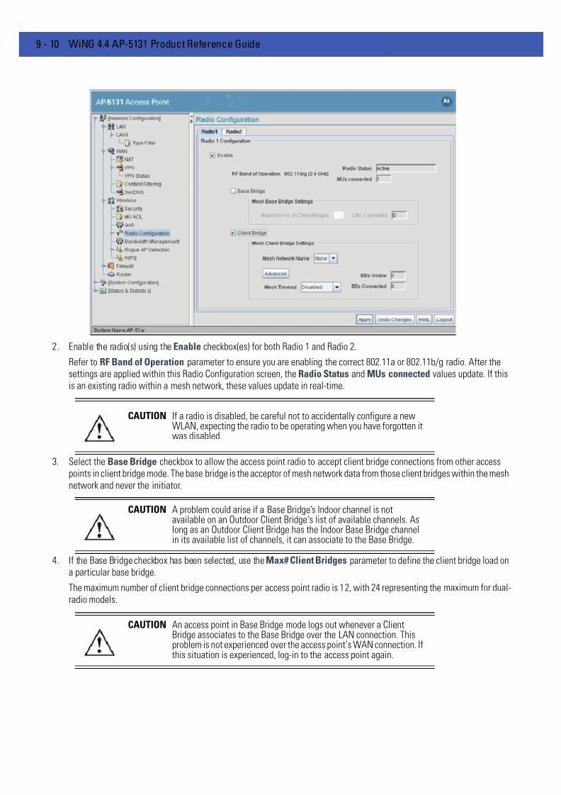
7/18/2019 Motorola AP 5131 Manual
http://slidepdf.com/reader/full/motorola-ap-5131-manual 538/613
9 - 10 WiNG 4.4 AP-5131 Product Reference Guide
2. Enable the radio(s) using the Enable checkbox(es) for both Radio 1 and Radio 2.
Refer to RF Band of Operation parameter to ensure you are enabling the correct 802.11a or 802.11b/g radio. After thesettings are applied within this Radio Configuration screen, the Radio Status and MUs connected values update. If thisis an existing radio within a mesh network, these values update in real-time.
3. Select the Base Bridge checkbox to allow the access point radio to accept client bridge connections from other accesspoints in client bridge mode. The base bridge is the acceptor of mesh network data from those client bridges within the meshnetwork and never the initiator.
4. If the Base Bridge checkbox has been selected, use the Max# Client Bridges parameter to define the client bridge load ona particular base bridge.
The maximum number of client bridge connections per access point radio is 12, with 24 representing the maximum for dual-radio models.
CAUTION If a radio is disabled, be careful not to accidentally configure a newWLAN, expecting the radio to be operating when you have forgotten itwas disabled.
CAUTION A problem could arise if a Base Bridge’s Indoor channel is notavailable on an Outdoor Client Bridge's list of available channels. Aslong as an Outdoor Client Bridge has the Indoor Base Bridge channelin its available list of channels, it can associate to the Base Bridge.
CAUTION An access point in Base Bridge mode logs out whenever a ClientBridge associates to the Base Bridge over the LAN connection. Thisproblem is not experienced over the access point’s WAN connection. Ifthis situation is experienced, log-in to the access point again.

7/18/2019 Motorola AP 5131 Manual
http://slidepdf.com/reader/full/motorola-ap-5131-manual 539/613
Configuring Mesh Networking 9 - 11
Once the settings within the Radio Configuration screen are applied (for an initial deployment), the current number of clientbridge connections for this specific radio displays within the CBs Connected field. If this is an existing radio within a meshnetwork, this value updates in real-time.
5. Select the Client Bridge checkbox to enable the access point radio to initiate client bridge connections with other mesh
network supported access points radios on the same WLAN.

7/18/2019 Motorola AP 5131 Manual
http://slidepdf.com/reader/full/motorola-ap-5131-manual 540/613
9 - 12 WiNG 4.4 AP-5131 Product Reference Guide
If the Client Bridge checkbox has been selected, use the Mesh Network Name drop-down menu to select the WLAN (ESS)the client bridge uses to establish a wireless link. The default setting, is (WLAN1). Motorola Solutions recommends creating(and naming) a WLAN specifically for mesh networking support to differentiate the Mesh supported WLAN from non-Meshsupported WLANs. For more information, see Configuring a WLAN for Mesh Networking Support on page 9-6
Once the settings within the Radio Configuration screen are applied (for an initial deployment), the current number of basebridges visible to the radio displays within the BBs Visible field, and the number of base bridges currently connected tothe radio displays within the BBs Connected field. If this is an existing radio within a mesh network, these values updatein real-time.
6. Click the Advanced button to define a prioritized list of access points to define mesh connection links.
7. Select the Automatic Link Selection checkbox to allow the access point to select the links used by the client bridge topopulate the mesh network. Selecting this checkbox prohibits the user from selecting the order base bridges are added tothe mesh network when one of the three associated base bridges becomes unavailable.
8. Refer to the Available Base Bridge List to view devices located by the access point using the WLAN selected from theRadio Configuration screen. Refer the following for information on located base bridges:
NOTE Ensure you have verified the radio configuration for both Radio 1 andRadio 2 before saving the existing settings and exiting the RadioConfiguration screen.v
NOTE Auto link selection is based on the RSSI and load. The client bridge willselect the best available link when the Automatic Link Selectioncheckbox is selected. Motorola Solutions recommends you do not disablethis option, as (when enabled) the access point will select the best base
bridge for connection.
MAC The MAC field displays the factory set hard-coded MAC address
that serves as a device identifier.
7/18/2019 Motorola AP 5131 Manual
http://slidepdf.com/reader/full/motorola-ap-5131-manual 541/613
Configuring Mesh Networking 9 - 13
9. Click Refresh at any time to update the list of available Base Bridge devices available to theaccess point.
10. Use the >> button to move a selected base bridge MAC address from Available Base Bridge List
11. Refer to the Preferred Base Bridge List for a prioritized list of base bridges the mesh network’s client bridge uses to
extend the mesh network’s coverage area and potentially provide redundant links. If a device does not appear on theAvailable Base Bridge List, there is no" way it can be moved to Preferred Base Bridge List as the device has not yet been"seen." However, if you know the MAC Address corresponding to that Base Bridge, you can add that to the Preferred Listusing the add button.
12. Highlight a MAC address from the Preferred Base Bridge List and click the Up button to assign that device’s MAC addressa higher priority and a greater likelihood of joining the mesh network if an association with another device is lost.
If a MAC address is not desirable as others but still worthy of being on the preferred list, select it, and click the Down buttonto decrease its likelihood of being selected as a member of the mesh network.
13. If a device MAC address is on the Preferred Base Bridge List and constitutes a threat as a potential member of the meshnetwork (poor RSSI etc.), select it and click the Remove button to exclude it from the preferred list.
If all of the members of the Preferred Base Bridge List constitute a risk as a member of the mesh network, click the Remove
All button. This is not recommended unless the preferred list can be re-populated with more desirable device MACaddresses from the Available Base Bridge List.
14. Click Ok to return to the Radio Configuration screen. Within the Radio Configuration screen, click Apply to save any changesmade within the Advanced Client Bridge Settings screen.
15. Click Cancel to undo any changes made within the Advanced Client Bridge Settings screen. This reverts all settings for thescreen to the last saved configuration.
16. If using a dual-radio model access point, refer to the Mesh Timeout drop-down menu (from within the Radio Configurationscreen) to define whether one of the access point’s radio’s beacons on an existing WLAN or if a client bridge radio uses anuplink connection. The Mesh Timeout value is not available on a single-radio access point, since the radio would have tostop beaconing and go into scan mode to determine if a base bridge uplink is lost. The following drop-down menu optionsare available:
RSSI The Relative Signal Strength Indicator (RSSI) displays the located
device’s signal strength with the associated access point in client
bridge mode. Use this information as criteria on whether to move a
particular device from the available list to the preferred list.
CHANN The CHANN displays the name of the channel that both theaccess point and base bridge use. A client bridge can only connect
to access points (Base Bridges) on the same channel. If the user
selects multiple base bridges on different channels, the access
point will only be able to connect to those bridges on the same
channel and the others will not be able to join this particular mesh
network.
Disabled When disabled, both radios are up at boot time and beaconing. If
one radio (radio 1) does not have a mesh connection, the other
radio (radio 2) is not affected. Radio 2 continues to beacon and
associate MUs, but MU's can only communicate amongst
themselves using the access point. Disabled is the default value.

7/18/2019 Motorola AP 5131 Manual
http://slidepdf.com/reader/full/motorola-ap-5131-manual 542/613
9 - 14 WiNG 4.4 AP-5131 Product Reference Guide
17. Click Apply to save any changes to the Radio Configuration screen. Navigating away from the screen without clicking Applyresults in all changes to the screens being lost.
18. Click Undo Changes (if necessary) to undo any changes made. Undo Changes reverts the settings displayed on the RadioConfiguration screen to the last saved configuration.
19. Click Logout to securely exit the access point applet. A prompt displays confirming the logout before the applet is closed.
Once the target radio has been enabled from the Radio Configuration screen, configure the radio’s properties by selectingit from the AP-51x1 menu tree.
For additional information on configuring the access point’s radio, see Configuring the 802.11a or 802.11b/g Radio on page5-42 . For two fictional deployment scenarios, see Mesh Network Deployment - Quick Setup on page 9-15 .
Upload Detect When Uplink Detect is selected, the access point only boots up the
radio configured as a client bridge. The access point boots up the
second radio as soon as the first mesh connection is established.
However, if the client bridge radio loses its uplink connection, the
second radio shuts down immediately.
Enabled If the mesh connection is down on one radio (radio 1), the other
radio (radio 2) is brought down and stops beaconing after the
timeout period (45 seconds). This allows the client bridge (radio 1)
to roam without dropping the MU's associated to radio 2. The
disadvantage is that radio 2 may beacon for the 45 second timeout
period and have to drop associated MU's because radio 1 could not
establish its uplink.
NOTE The Mesh Time Out variable overrides the Ethernet Port Time Out (EPTO)setting on the LAN page when the access point is in bridge mode. As longas the mesh is down, the access point acts in accordance to the MeshTime Out setting regardless of the state of the Ethernet. However, if the
Ethernet goes down and the mesh link is still up, the EPTO takes effect.
CAUTION When defining a Mesh configuration and changes are saved, themesh network temporarily goes down. The mesh network isunavailable because the access point radio goes down when applyingthe changes. This can be problematic for users making changes withina deployed mesh network. If updating the mesh network using a LANconnection, the access point applet loses connection and theconnection must be re-instated. If updating the mesh network using aWAN connection, the applet does not lose connection, but the meshnetwork is unavailable until the changes have been applied.
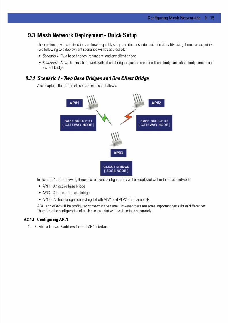
7/18/2019 Motorola AP 5131 Manual
http://slidepdf.com/reader/full/motorola-ap-5131-manual 543/613
Configuring Mesh Networking 9 - 15
9.3 Mesh Network Deployment - Quick Setup
This section provides instructions on how to quickly setup and demonstrate mesh functionality using three access points.Two following two deployment scenarios will be addressed:
• Scenario 1 - Two base bridges (redundant) and one client bridge• Scenario 2 - A two hop mesh network with a base bridge, repeater (combined base bridge and client bridge mode) and
a client bridge.
9.3.1 Scenario 1 - Two Base Bridges and One Client Bridge
A conceptual illustration of scenario one is as follows:
In scenario 1, the following three access point configurations will be deployed within the mesh network:
• AP#1 - An active base bridge
• AP#2 - A redundant base bridge
• AP#3 - A client bridge connecting to both AP#1 and AP#2 simultaneously.
AP#1 and AP#2 will be configured somewhat the same. However there are some important (yet subtle) differences.Therefore, the configuration of each access point will be described separately.
9.3.1.1 Configuring AP#1:
1. Provide a known IP address for the LAN1 interface.

7/18/2019 Motorola AP 5131 Manual
http://slidepdf.com/reader/full/motorola-ap-5131-manual 544/613
9 - 16 WiNG 4.4 AP-5131 Product Reference Guide
2. Assign a Mesh STP Priority of 40000 to LAN1 Interface.
3. Define a mesh supported WLAN.
NOTE Enable the LAN1 Interface of AP#1 as a DHCP Server if you intend toassociate MUs and require them to obtain an IP address via DHCP.
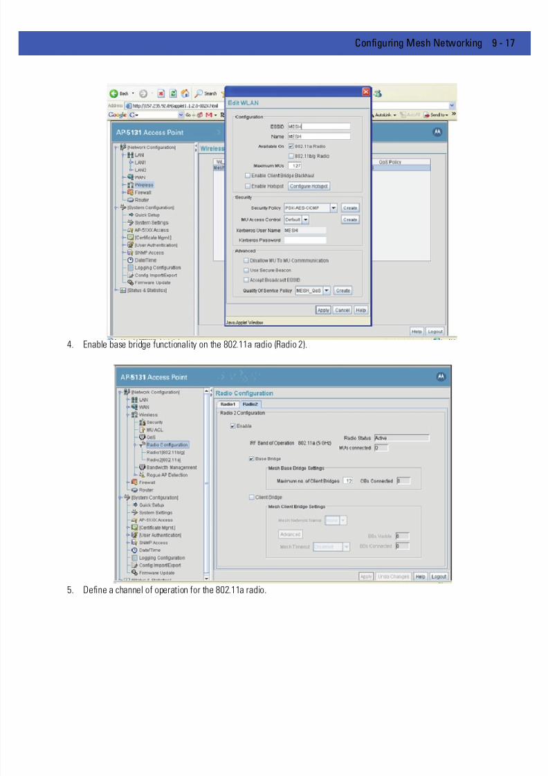
7/18/2019 Motorola AP 5131 Manual
http://slidepdf.com/reader/full/motorola-ap-5131-manual 545/613
Configuring Mesh Networking 9 - 17
4. Enable base bridge functionality on the 802.11a radio (Radio 2).
5. Define a channel of operation for the 802.11a radio.

7/18/2019 Motorola AP 5131 Manual
http://slidepdf.com/reader/full/motorola-ap-5131-manual 546/613
9 - 18 WiNG 4.4 AP-5131 Product Reference Guide
6. If needed, create another WLAN mapped to the 802.11bg radio if 802.11bg support is required for MUs on that 802.11 band.
9.3.1.2 Configuring AP#2
AP#2 can be configured the same as AP#1 with the following exceptions:
• Assign an IP Address to the LAN1 Interface different than that of AP#1.
• Assign a higher Mesh STP Priority 50000 to the AP#2 LAN1 Interface.

7/18/2019 Motorola AP 5131 Manual
http://slidepdf.com/reader/full/motorola-ap-5131-manual 547/613
Configuring Mesh Networking 9 - 19
.
9.3.1.3 Configuring AP#3
To define the configuration for AP#3 (a client bridge connecting to both AP#1 and AP#2 simultaneously):
1. Provide a known IP address for the LAN1 interface..
2. Assign the maximum value (65535) for the Mesh STP Priority.
NOTE In a typical deployment, each base bridge can be configured for a MeshSTP Priority of 50000. In this example, different values are used to forceAP#1 to be the forwarding link since it's a small mesh network (of onlythree APs) with AP within close proximity of one another.
NOTE Ensure AP#1 and AP#2 use the same channel for each 802.11a radio, orthe APs will not be able to “hear” each other over different channels.

7/18/2019 Motorola AP 5131 Manual
http://slidepdf.com/reader/full/motorola-ap-5131-manual 548/613
9 - 20 WiNG 4.4 AP-5131 Product Reference Guide
3. Create a mesh supported WLAN with the Enable Client Bridge Backhaul option selected.
NOTE This WLAN should not be mapped to any radio. Therefore, leave both ofthe “Available On” radio options unselected
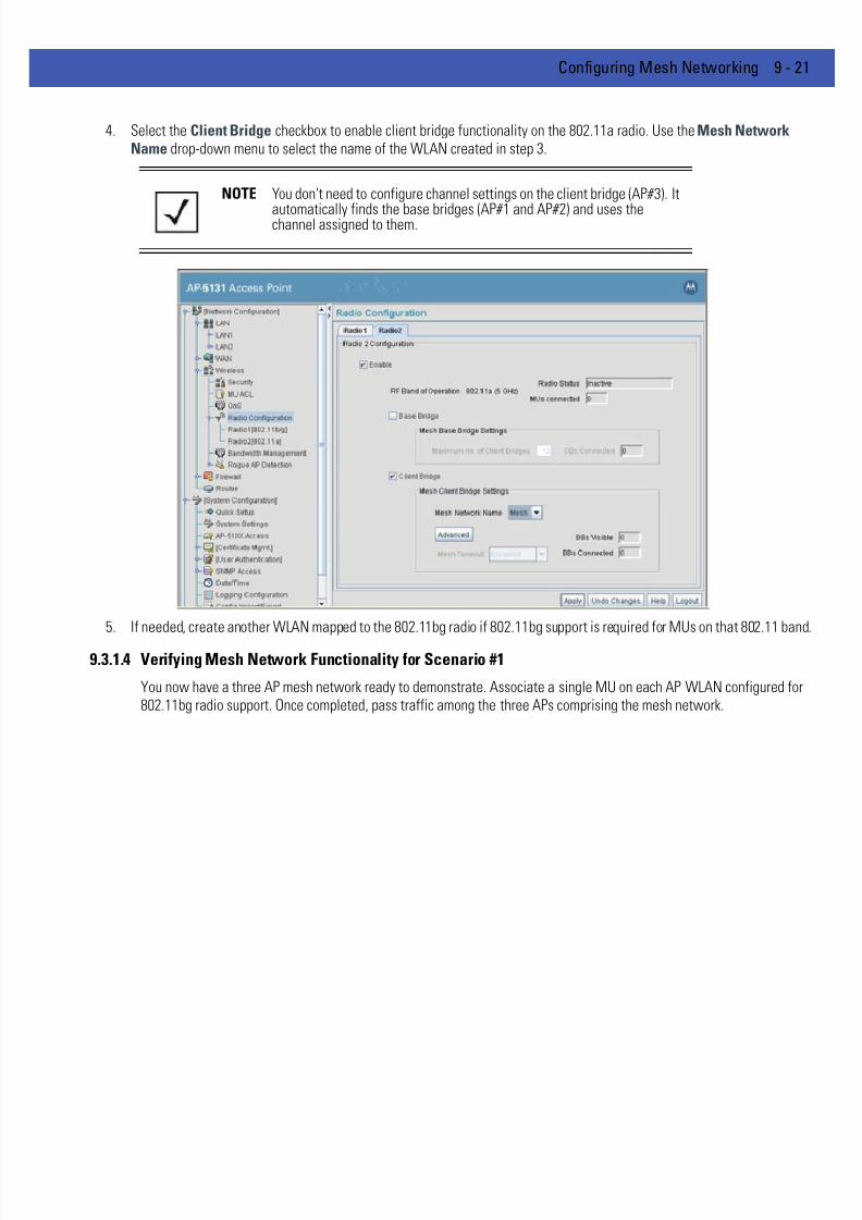
7/18/2019 Motorola AP 5131 Manual
http://slidepdf.com/reader/full/motorola-ap-5131-manual 549/613
Configuring Mesh Networking 9 - 21
4. Select the Client Bridge checkbox to enable client bridge functionality on the 802.11a radio. Use the Mesh NetworkName drop-down menu to select the name of the WLAN created in step 3.
5. If needed, create another WLAN mapped to the 802.11bg radio if 802.11bg support is required for MUs on that 802.11 band
9.3.1.4 Verifying Mesh Network Functionality for Scenario #1
You now have a three AP mesh network ready to demonstrate. Associate a single MU on each AP WLAN configured for802.11bg radio support. Once completed, pass traffic among the three APs comprising the mesh network.
NOTE You don't need to configure channel settings on the client bridge (AP#3). It
automatically finds the base bridges (AP#1 and AP#2) and uses thechannel assigned to them.

7/18/2019 Motorola AP 5131 Manual
http://slidepdf.com/reader/full/motorola-ap-5131-manual 550/613
9 - 22 WiNG 4.4 AP-5131 Product Reference Guide
9.3.2 Scenario 2 - Two Hop Mesh Network with a Base Bridge Repeater and a Client Bridge
A conceptual illustration of scenario two is as follows:
By default, the mesh algorithm runs an automatic link selection algorithm to determine the best possible active andredundant links. If member APs are not far apart (in physical distance), the algorithm intelligently chooses a single hop linkto forward data. To force APs to use multiple hops for demonstrations, use manual links.
In scenario 2, the following three AP configurations comprise the mesh network:
• AP#1 is a base bridge
• AP#2 is a repeater (client bridge/base bridge combination)
• AP#3 is a client b ridge
9.3.2.1 Configuring AP#1
The setup of AP#1 within this usage scenario is exactly the same as the AP#1 configuration within Scenario 1 - Two BaseBridges and One Client Bridge for step by step instructions for configuring AP#1, see Configuring AP#1: on page 9-15 . Oncecompleted, return toConfiguring AP#2 on page 9-22 within this section.
9.3.2.2 Configuring AP#2AP#2 requires the following modifications from AP#2 in the previous scenario to function in base bridge/client bridgerepeater mode.
1. Enable client bridge backhaul on the mesh supported WLAN.

7/18/2019 Motorola AP 5131 Manual
http://slidepdf.com/reader/full/motorola-ap-5131-manual 551/613
Configuring Mesh Networking 9 - 23
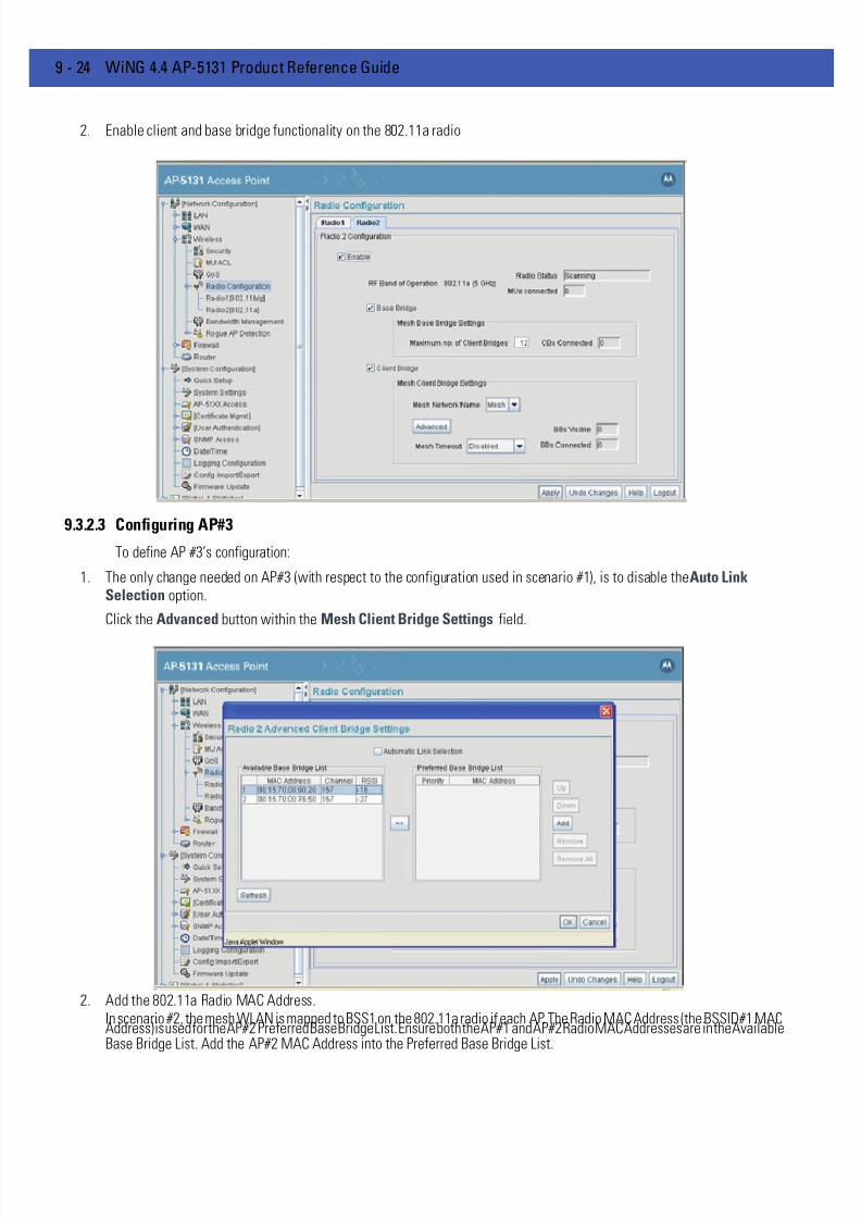
7/18/2019 Motorola AP 5131 Manual
http://slidepdf.com/reader/full/motorola-ap-5131-manual 552/613
9 - 24 WiNG 4.4 AP-5131 Product Reference Guide
2. Enable client and base bridge functionality on the 802.11a radio
9.3.2.3 Configuring AP#3
To define AP #3’s configuration:
1. The only change needed on AP#3 (with respect to the configuration used in scenario #1), is to disable the Auto LinkSelection option.
Click the Advanced button within the Mesh Client Bridge Settings field.
2. Add the 802.11a Radio MAC Address.In scenario #2, the mesh WLAN is mapped to BSS1 on the 802.11a radio if each AP. The Radio MAC Address (the BSSID#1 MACAddress) is used for the AP#2 Preferred Base Bridge List. Ensure both the AP#1 and AP#2 Radio MAC Addresses are in the AvailableBase Bridge List. Add the AP#2 MAC Address into the Preferred Base Bridge List.

7/18/2019 Motorola AP 5131 Manual
http://slidepdf.com/reader/full/motorola-ap-5131-manual 553/613
Configuring Mesh Networking 9 - 25
3. Determine the Radio MAC Address and BSSID MAC Addresses.

7/18/2019 Motorola AP 5131 Manual
http://slidepdf.com/reader/full/motorola-ap-5131-manual 554/613
9 - 26 WiNG 4.4 AP-5131 Product Reference Guide
9.3.2.4 Verifying Mesh Network Functionality for Scenario #2
You now have a three AP demo multi-hop mesh network ready to demonstrate. Associate an MU on the WLANs configuredon the 802.11bg radio for each AP and pass traffic among the members of the mesh network.
7/18/2019 Motorola AP 5131 Manual
http://slidepdf.com/reader/full/motorola-ap-5131-manual 555/613
Configuring Mesh Networking 9 - 27
9.4 Mesh Networking Frequently Asked Questions
The following scenarios represent issues that could be encountered and resolved when defining anAP-5131 or AP-5181 mesh configuration:
9.4.0.0.1 Mesh Deployment Issue 1 - Client Bridge can only connect to one of two Base BridgesYou have two access points configured as base bridges (AP1, AP2) and one access point defined as a as a client bridge(AP3). However, the client bridge is able to connect to only one of the base bridges.
9.4.0.0.2 Resolution
Check the mesh backhaul radio channel configuration on both base bridges (AP1, AP2). They need to use the same channelso the client bridge can connect to both simultaneously.
9.4.0.0.3 Mesh Deployment Issue 2 - Faulty Client Bridge Connectivity
You have configured three access points in mesh mode; one base bridge (AP1), one client bridge/base bridge (AP2) andone client bridge (AP3). However, the client bridge (AP3) is connecting to both AP1 and AP2 and using its link to base bridge
(AP1) to forward traffic.9.4.0.0.4 Resolution
This is valid behavior, you see this when your mesh APs are close enough (in proximity) so the client bridge can see boththe base bridges (AP1, AP2), in which case it forms two links, one each to AP1 and AP2. Since the link to AP1 is the shortestpath in terms of number of hops, AP3 uses that link to forward traffic.
9.4.0.0.5 Mesh Deployment Issue 3 - Cannot select a WLAN name for a Client Bridge
You created a WLAN for mesh backhaul on an AP needed as a client bridge, but you don't get to select the WLAN namein the Mesh Network Name drop down menu. Why?
9.4.0.0.6 Resolution
Check the WLAN configuration to ensure you have enabled the Enable Client Bridge Backhaul option.
7/18/2019 Motorola AP 5131 Manual
http://slidepdf.com/reader/full/motorola-ap-5131-manual 556/613
9 - 28 WiNG 4.4 AP-5131 Product Reference Guide
Mesh Deployment Issue 4 - Do I need to map a WLAN to a radio when configuring mesh backhaulon a Client Bridge?
When creating a mesh backhaul WLAN on a client bridge only AP, do you need to map the WLAN on a radio?
Resolution
No, a client bridge only AP behaves just like an MU! It scans for base bridges and forms connections to them. It doesn'tneed to beacon on that WLAN. Therefore, while creating a mesh backhaul WLAN on a client bridge only AP, just enablethe Enable Client Bridge Backhaul option.
Mesh Deployment Issue 5 - Do I need to use secure beacons on a mesh backhaul supported WLAN?
Can I use secure beacons on the mesh backhaul supported WLAN?
9.4.0.0.7 Resolution
Yes, you can enable a secure beacon on a mesh backhaul supported WLAN. In fact, it is a Motorola Solutionsrecommended practice.
9.4.0.0.8 Mesh Deployment Issue 6 - Is my mesh topology complete?
How can I determine if all my mesh APs are connected and the mesh topology is complete?
9.4.0.0.9 Resolution
Each mesh AP has a Known AP Table (available in the applet, CLI and SNMP). All APs (whether they are supporting meshor not) periodically exchange ID messages notifying their presence to one another. Review the Known AP Table on anymesh supported AP to determine if you have all required APs connected to the mesh topology.
9.4.0.0.10Mesh Deployment Issue 7 - Can MUs roam within a mesh topology?
Can MUs connected to a mesh AP roam seemlessly among other MUs and wired access points?
9.4.0.0.11Resolution
Yes, MUs on a mesh APs can roam seemlessly throughout the mesh network as well as withnon-mesh access points on the wired network.
9.4.0.0.12Mesh Deployment Issue 8 - Can I mesh between an AP-5131 and an AP-5181?
Can you mesh between an AP-5131 and an AP-5181?
9.4.0.0.13Resolution
Yes, both the AP-5131 and AP-5181 model access points are identical from a software deployment standpoint. so it is asupported configuration for AP-5131s and AP-5181s to exist in a single topology.
9.4.0.0.14Mesh Deployment Issue 9 - Can I mesh between and an access point and an AP300?
Can you mesh between a AP-5131, AP-5181 and an AP300 model access port?
9.4.0.0.15Resolution
No, an AP300 does not support mesh networking. so you won't be able to mesh between two AP300s or between an AP300and an AP-5131 or AP-5181.
9.4.0.0.16Mesh Deployment Issue 10 - Can I mesh between an AP-5131/AP-5181 and anAP-4131?
Can I mesh between a newer AP-5131, AP-5181 and a legacy AP-4131 model access point?

7/18/2019 Motorola AP 5131 Manual
http://slidepdf.com/reader/full/motorola-ap-5131-manual 557/613
Configuring Mesh Networking 9 - 29
9.4.0.0.17Resolution
No, an AP-4131 only supports wireless bridging like Cisco IOS APs. Consequently, an AP-4131 is not compatible with anAP-5131 or AP-5181 supported mesh deployment.
9.4.0.0.18Mesh Deployment Issue 11 - Can I update firmware/configuration files across a mesh backhaul?
Can I update device firmware over the mesh backhaul on a client bridge or repeater AP with no wired connectivity?
9.4.0.0.19Resolution
Yes, both the AP-5131 and AP-5181 support wireless firmware updates.
9.4.0.0.20Mesh Deployment Issue 12 - Can I perform firmware/configuration file updates with DHCP options?
Can I use the AP’s Automatic Firmware/Configuration update functionalities with DHCP Options on the AP for mesh nodesas well?
9.4.0.0.21Resolution
Yes, mesh nodes also support Automatic Firmware/Configuration updates using DHCP Options. Make sure you create
DHCP reservations for each mesh node and add an appropriate configuration file to each one of them. If you don’t, the basebridge configuration file could get applied on a client bridge or repeater and you will loose connectivity to that AP.
9.4.0.0.22Mesh Deployment Issue 13 - Why do I lose connectivity when updating configurations?
When I make a configuration change and apply the changes on a client bridge or repeater, I momentarily loose connectivityto that AP, why?
9.4.0.0.23Resolution
That is expected behavior, when you make a configuration change on a mesh supported AP, it brings the radio driver downand then back up again. Consequently, the AP needs to re-establish its mesh connection after saving the configuration.
9.4.0.0.24Mesh Deployment Issue 14 - Will an existing client bridge see a new base bridge or repeater?
If I add a new base bridge or repeater to an existing mesh topology, will my current client bridges see it and connect to it?
9.4.0.0.25Resolution
Yes, all client bridges perform periodic background scanning - both passively (by sniffing the air for beacons) and actively(by sending Probe Requests). Therefore, a client bridge automatically detects the presence of a new base bridge orrepeater added to the mesh network topology and forms a seam less connection without affecting current operation.
9.4.0.0.26Mesh Deployment Issue 15 - Can a mesh supported AP react to changing RF conditions?
If RF conditions change, will a mesh supported AP automatically detect and re-route traffic on its backup link or look fornew links if all current links are exhausted?
9.4.0.0.27Resolution
Yes, all mesh nodes have built in dynamic link switching and auto-recovery mechanisms that ensure they adapt to changingRF conditions.

7/18/2019 Motorola AP 5131 Manual
http://slidepdf.com/reader/full/motorola-ap-5131-manual 558/613
9 - 30 WiNG 4.4 AP-5131 Product Reference Guide
7/18/2019 Motorola AP 5131 Manual
http://slidepdf.com/reader/full/motorola-ap-5131-manual 559/613
CHAPTER 10 ADAPTIVE AP
10.1 Adaptive AP Overview
An adaptive AP (AAP) is an AP-51XX access point that can adopt like an AP300 (L3). The management of an AAP isconducted by the switch, once the access point connects to a Motorola Solutions WS5100, RFS6000 or RFS7000 modelswitch and receives its AAP configuration.
An AAP provides:
• local 802.11 traffic termination
• local encryption/decryption
• local traffic bridging
• the tunneling of centralized traffic to the wireless switchAn AAP’s switch connection can be secured using IP/UDP or IPSec depending on whether a secure WAN link from a remotesite to the central site already exists.
The switch can be discovered using one of the following mechanisms:
• DHCP
• Switch fully qualified domain name (FQDN)
• Static IP addresses
The benefits of an AAP deployment include:
• Centralized Configuration Management & Compliance - Wireless configurations across distributed sites can becentrally managed by the wireless switch or cluster.
• WAN Survivability - Local WLAN services at a remote sites are unaffected in the case of a WAN outage.
• Securely extend corporate WLAN's to stores for corporate visitors - Small home or office deployments can utilize thefeature set of a corporate WLAN from their remote location.
• Maintain local WLAN's for in store applications - WLANs created and supported locally can be concurrently supportedwith your existing infrastructure.
10.1.1 Where to Go From Here
Refer to the following for a further understanding of AAP operation:

7/18/2019 Motorola AP 5131 Manual
http://slidepdf.com/reader/full/motorola-ap-5131-manual 560/613
10 - 2 WiNG 4.4 AP-5131 Product Reference Guide
• Adaptive AP Management
• Types of Adaptive APs
• Licensing
• Switch Discovery • Securing a Configuration Channel Between Switch and AP
• Adaptive AP WLAN Topology
• Configuration Updates
• Securing Data Tunnels between the Switch and AAP
• Adaptive AP Switch Failure
• Remote Site Survivability (RSS)
• Adaptive Mesh Support
For an understanding of how AAP support should be configured for the access point and its connected switch, see How
the AP Receives its Adaptive Configuration on page 10-9 .For an overview of how to configure both the access point and switch for basic AAP connectivity and operation, seeEstablishing Basic Adaptive AP Connectivity on page 10-11.
To configure the access point’s switch discovery method and connection medium, seeAdaptive AP Setup on page 4-6 .
10.1.2 Adaptive AP Management
An AAP can be adopted, configured and managed like a thin access port from the wireless switch.
Once an access point connects to a switch and receives its AAP configuration, its WLAN and radio configuration is similarto a thin access port. An AAP's radio mesh configuration can also be configured from the switch. However, non-wirelessfeatures (DHCP, NAT, Firewall etc.) cannot be configured from the switch and must be defined using the access point's
resident interfaces before its conversion to an AAP.
10.1.3 Types of Adaptive APs
Two low priced AP-5131 SKU configurations are being introduced allowing customers to take advantage of the adaptiveAP architecture and to reduce deployment costs.
These dependent mode AP configurations are a software variant of the AP-5131 and will be functional only after theaccess point is adopted by a wireless switch. After adoption, the dependent mode AP receives its configuration from theswitch and starts functioning like other adaptive access points. For ongoing operation, the dependent mode AP-5131 needsto maintain connectivity with the switch. If switch connectivity is lost, the dependent mode AP-5131 continues operatingas a stand-alone access point for a period of 3 days before resetting and executing the switch discovery algorithm again.
NOTE To support AAP functionality, a WS5100 model switch must be running
firmware version 3.1 or higher, whereas a RFS6000 or RFS7000 modelswitch must be running firmware version 1.1 or higher. The access pointmust running firmware version 2.0 or higher to be converted into an AAP.
NOTE An AAP cannot support a firmware download from the wireless switch.

7/18/2019 Motorola AP 5131 Manual
http://slidepdf.com/reader/full/motorola-ap-5131-manual 561/613
Adaptive AP 10 - 3
A dependent mode AP cannot be converted into a standalone AP-51XX through a firmware change. Refer to AP-51xxHardware/ Software Compatibility Matrix within the release notes bundled with the access point firmware.
10.1.4 Licensing
An AAP uses the same licensing scheme as a thin access port. This implies an existing license purchased with a switchcan be used for an AAP deployment. Regardless of how many AP300 and/or AAPs are deployed, you must ensure thelicense used by the switch supports the number of radio ports (both AP300s and AAPs) you intend to adopt.
10.1.5 Switch Discovery
For an AP-51xx to function as an AAP (regardless of mode), it needs to connect to a switch to receive its configuration.There are two methods of switch discovery:
• Auto Discovery using DHCP
• Manual Adoption Configuration v
10.1.5.1 Auto Discovery using DHCP
Extended Global Options 189, 190, 191, 192 can be used or Embedded Option 43 - Vendor Specific options can beembedded in Option 43 using the vendor class identifier: Motorola SolutionsAP.51xx-V2-0-0.
** The AP-51xx uses an encryption key to hash passphrases and security keys. To obtain the encryption passphrase,configure an AP-51xx with the passphrase and export the configuration file.
AP-5131-13040-D-WR Dependent AP-5131 Dual Radio (Switch Required)
AP-5131-40020-D-WR Dependent AP-5131 Single Radio (Switch Required)
NOTE To support switch discovery, a WS5100 model switch must be runningfirmware version 3.1 or higher, whereas a RFSW6000 or RFS7000 modelswitch must be running firmware version 1.1 or higher. The access pointmust running firmware version 2.0 or higher.
Code Data Type
List of Switch IP addresses
(separate by comma, semi-colon, or space delimited)
188 String
Switch FQDN 190 String
AP-51XX Encryption IPSec Passphrase (Hashed) ** 191 String
AP-51XX switch discovery mode
1 = auto discovery enable
2 = auto discover enabled (using IPSec)
192 String

7/18/2019 Motorola AP 5131 Manual
http://slidepdf.com/reader/full/motorola-ap-5131-manual 562/613
10 - 4 WiNG 4.4 AP-5131 Product Reference Guide
10.1.5.2 Manual Adoption Configuration
A manual switch adoption of an AAP can be conducted using:
• Static FQDN - A switch fully qualified domain name can be specified to perform a DNS lookup and switch discovery.
• Static IP addresses - Up to 12 switch IP addresses can be manually specified in an ordered list the AP can choose from.When providing a list, the AAP tries to adopt based on the order in which they are listed (from 1-12.
)
The WAN has no PoE support and has a default static AP address of 10.1.1.1/8.
10.1.6 Securing a Configuration Channel Between Switch and AP
Once an access point obtains a list of available switches, it begins connecting to each. The switch can be either on theLAN or WAN side of the access point to provide flexibility in the deployment of the network. If the switch is on the access
point’s LAN, ensure the LAN subnet is on a secure channel. The AP will connect to the switch and request a configuration.
10.1.7 Adaptive AP WLAN Topology
An AAP can be deployed in the following WLAN topologies:
• Extended WLANs - Extended WLANs are the centralized WLANs created on the switch
• Independent WLANs - Independent WLANs are local to an AAP and can be configured from the switch. You mustspecify a WLAN as independent to stop traffic from being forwarded to the switch. Independent WLANs behave likeWLANs on a standalone access point.
• Both - Extended and independent WLANs are configured from the switch and operate simultaneously.
NOTE An AAP can use it's LAN or WAN Ethernet interface to adopt. The LAN isPoE and DHCP enabled by default.

7/18/2019 Motorola AP 5131 Manual
http://slidepdf.com/reader/full/motorola-ap-5131-manual 563/613
Adaptive AP 10 - 5
10.1.8 Configuration Updates
An AAP receives its configuration from the switch initially as part of its adoption sequence. Subsequent configurationchanges on the switch are reflected on an AAP when applicable.
An AAP applies the configuration changes it receives from the switch after 30 seconds from the last received switchconfiguration message. When the configuration is applied on the AAP, the radios shutdown and re-initialize (this processtakes less than 2 seconds) forcing associated MUs to be deauthenticated. MUs are quickly able to associate.
10.1.9 Securing Data Tunnels between the Switch and AAP
If a secure link (site-to-site VPN) from a remote site to the central location already exists, the AAP does not require IPSec
be configured for adoption.
For sites with no secure link to the central location, an AAP can be configured to use an IPSec tunnel (with AES 256encryption) for adoption. The tunnel configuration is automatic on the AAP side and requires no manual VPN policy beconfigured. On the switch side, configuration updates are required to adopt the AAP using an IPSec tunnel.
To review a sample AAP configuration, see Sample Switch Configuration File for IPSec and Independent WLAN on page10-17 .
10.1.10 Adaptive AP Switch Failure
In the event of a switch failure, an AAP's independent WLAN continues to operate without disruption. The AAP attemptsto connect to other switches (if available) in background. Extended WLANs are disabled once switch adoption is lost.
When a new switch is discovered and a connection is secured, an extended WLAN can be enabled.If a new switch is located, the AAP synchronizes its configuration with the located switch once adopted. If Remote SiteSurvivability (RSS) is disabled, the independent WLAN is also disabled in the event of a switch failure.
10.1.11 Remote Site Survivability (RSS)
RSS can be used to turn off RF activity on an AAP if it loses adoption (connection) to the switch.
NOTE For a review of some important considerations impacting the use ofextended and independent WLANs within an AAP deployment, seeAdaptive AP Deployment Considerations on page 10-16 .
RSS State Independent WLANs Extended WLANs
RSS Enabled WLAN continues beaconing WLAN continues beaconing but AP does allow
clients to associate on that WLAN
RSS Disabled WLAN stops beaconing WLAN stops beaconing
NOTE For a dependant AAP, independent WLANs continue to beacon for threedays in the absence of a switch.
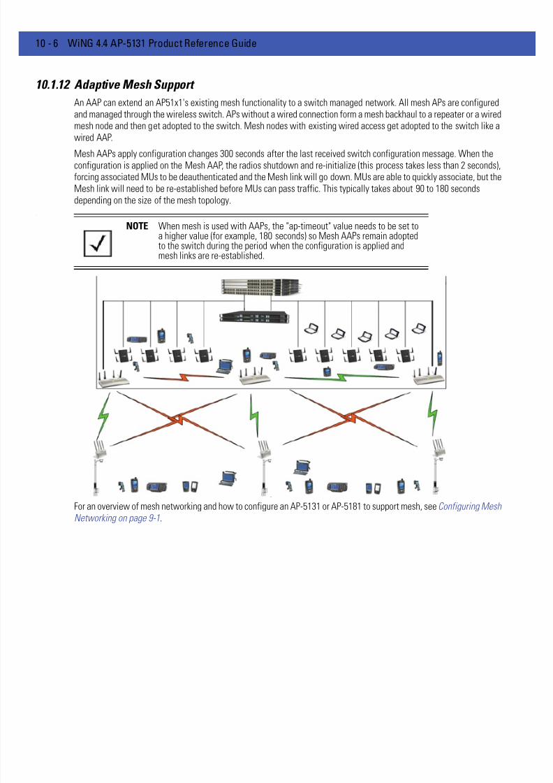
7/18/2019 Motorola AP 5131 Manual
http://slidepdf.com/reader/full/motorola-ap-5131-manual 564/613
10 - 6 WiNG 4.4 AP-5131 Product Reference Guide
10.1.12 Adaptive Mesh Support
An AAP can extend an AP51x1's existing mesh functionality to a switch managed network. All mesh APs are configuredand managed through the wireless switch. APs without a wired connection form a mesh backhaul to a repeater or a wiredmesh node and then get adopted to the switch. Mesh nodes with existing wired access get adopted to the switch like a
wired AAP.
Mesh AAPs apply configuration changes 300 seconds after the last received switch configuration message. When theconfiguration is applied on the Mesh AAP, the radios shutdown and re-initialize (this process takes less than 2 seconds),forcing associated MUs to be deauthenticated and the Mesh link will go down. MUs are able to quickly associate, but theMesh link will need to be re-established before MUs can pass traffic. This typically takes about 90 to 180 secondsdepending on the size of the mesh topology.
.
For an overview of mesh networking and how to configure an AP-5131 or AP-5181 to support mesh, see Configuring MeshNetworking on page 9-1.
NOTE When mesh is used with AAPs, the "ap-timeout" value needs to be set toa higher value (for example, 180 seconds) so Mesh AAPs remain adoptedto the switch during the period when the configuration is applied andmesh links are re-established.

7/18/2019 Motorola AP 5131 Manual
http://slidepdf.com/reader/full/motorola-ap-5131-manual 565/613
Adaptive AP 10 - 7
10.2 Supported Adaptive AP Topologies
For this version 2.0 release of the access point firmware, the following AAP topologies are supported:
• Extended WLANs Only
• Independent WLANs Only
• Extended WLANs with Independent WLANs
• Extended WLAN with Mesh Networking
10.2.1 Topology Deployment Considerations
When reviewing the AAP topologies describes in the section, be cognizant of the following considerations to optimize theeffectiveness of the deployment:
• An AAP firmware upgrade will not be performed at the time of adoption from the wireless switch. Instead, the firmwareis upgraded using the AP-51x1’s firmware update procedure (manually or using the DHCP Auto Update feature).
• An AAP can use its LAN1 interface or WAN interface for adoption. The default gateway interface is set to LAN1. If theWAN Interface is used, explicitly configure WAN as the default gateway interface.
• Motorola Solutions recommends using the LAN1 interface for adoption in multi-cell deployments.
• If you have multiple independent WLANs mapped to different VLANs, the AAP's LAN1 interface requires trunking beenabled with the correct management and native VLAN IDs configured. Additionally, the AAP needs to be connectedto a 802.1q trunk port on the wired switch.
• Be aware IPSec Mode supports NAT Traversal (NAT-T).

7/18/2019 Motorola AP 5131 Manual
http://slidepdf.com/reader/full/motorola-ap-5131-manual 566/613
10 - 8 WiNG 4.4 AP-5131 Product Reference Guide
10.2.2 Extended WLANs Only
An extended WLAN configuration forces all MU traffic through the switch. No wireless traffic is locally bridged by the AAP.
Each extended WLAN is mapped to the access point's virtual LAN2 subnet. By default, the access point's LAN2 is notenabled and the default configuration is set to static with IP addresses defined as all zeros. If the extended VLAN optionis configured on the switch, the following configuration updates are made automatically:
• The AAP’s LAN2 subnet becomes enabled
• All extended VLANs are mapped to LAN2.
10.2.3 Independent WLANs Only
An independent WLAN configuration forces all MU traffic be bridged locally by the AAP. No wireless traffic is tunneledback to the switch. Each extended WLAN is mapped to the access point's LAN1 interface. The only traffic between theswitch and the AAP are control messages (for example, heartbeats, statistics and configuration updates).
10.2.4 Extended WLANs with Independent WLANs
An AAP can have both extended WLANs and independent WLANs operating in conjunction. When used together, MUtraffic from extended WLANs go back to the switch and traffic from independent WLANs is bridged locally by the AP.
All local WLANs are mapped to LAN1, and all extended WLANs are mapped to LAN2.
10.2.5 Extended WLAN with Mesh Networking
Mesh networking is an extension of the existing wired network. There is no special configuration required, with theexceptions of setting the mesh and using it within one of the two extended VLAN configurations and defining an accesspoint radio as a preferred base bridge.
NOTE MUs on the same WLAN associated to the AAP can communicate locallyat the AP Level without going through the switch. If this scenario isundesirable, the access point's MU-to-MU disallow option should beenabled. To enable the access point’s MU-to-MU disallow option, seeCreating/Editing Individual WLANs on page 5-23 .
NOTE The mesh backhaul WLAN must be an independent WLAN mapped toLAN1. The switch enforces the WLAN be defined as an independentWLAN by automatically setting the WLAN to independent when backhaulis selected. The AP ensures the backhaul WLAN be put on LAN1.

7/18/2019 Motorola AP 5131 Manual
http://slidepdf.com/reader/full/motorola-ap-5131-manual 567/613
Adaptive AP 10 - 9
10.3 How the AP Receives its Adaptive Configuration
An AAP does not require a separate "local" or "running" configuration. Once enabled as an AAP, the AP obtains itsconfiguration from the switch. If the AP’s WAN link fails, it continues to operate using the last valid configuration until itslink is re-established and a new configuration is pushed down from the switch. There is no separate file-basedconfiguration stored on the switch.
Only WLAN, VLAN extension and radio configuration items are defined for the AAP by its connected switch. None of theother access point configuration items (RADIUS, DHCP, NAT, Firewall etc.) are configurable from the connected switch.
After the AP downloads a configuration file from the switch, it obtains the version number of the image it should berunning. The switch does not have the capacity to hold the access point’s firmware image and configuration. The accesspoint image must be downloaded using a means outside the switch. If there is still an image version mismatch betweenwhat the switch expects and what the AAP is running, the switch will deny adoption.
10.3.0.0.1Adaptive AP Pre-requisites
Converting an AP-5131 or AP-5181 model access point into an AAP requires:
• A version 2.0 or higher firmware running on the access point.• A Motorola Solutions WS5100 (running firmware version 3.1 or later) or a RFS6000/RFS7000 (running firmware version
1.1 or later) switch.
• The appropriate switch licenses providing AAP functionality on the switch.
• The correct password to authenticate and connect the adaptive to the switch.
10.3.0.0.2Configuring the Adaptive AP for Adoption by the Switch
1. An AAP needs to find and connect to the switch. To ensure this connection:
• Configure the switch’s IP address on the AAP
• Provide the switch IP address using DHCP option 189 on a DHCP server. The IP address is a comma delimited string
of IP addresses. For example "157.235.94.91, 10.10.10.19". There can be a maximum of 12 IP addresses.• Configure the switch’s FQDN on the AAP. The AAP can use this to resolve the IP address of the switch.
2. Use the switch’s secret password on the AAP for the switch to authenticate it.
For additional information on defining the connection medium used by the access point t to receive an AAP configuration,see Adaptive AP Setup on page 4-6 .
To avoid a lengthy broken connection with the switch, Motorola Solutions recommends generating an SNMP trap when theAAP loses adoption with the switch.
10.3.0.0.3Configuring the Switch for Adaptive AP Adoption
The tasks described below are configured on a Motorola Solutions WS5100 or a RFS6000/RFS7000 model switch. Forinformation on configuring the switch for AAP support, seehttp://support.symbol.com/support/product/manuals.do .
To adopt an AAP on a switch:
1. Ensure enough licenses are available on the switch to adopt the required number of AAPs.
2. As soon as the AAP displays in the adopted list:
NOTE For additional information (in greater detail) on the AP configurationactivities described above, see Adaptive AP Configuration on page 10-11.

7/18/2019 Motorola AP 5131 Manual
http://slidepdf.com/reader/full/motorola-ap-5131-manual 568/613
10 - 10 WiNG 4.4 AP-5131 Product Reference Guide
Adjust each AAP’s radio configuration as required. This includes WLAN-radio mappings and radio parameters. WLAN-VLANmappings and WLAN parameters are global and cannot be defined on a per radio basis. WLANs can be assigned to a radioas done today for an AP300 model access port. Optionally, configure WLANs as independent and assign to AAPs as needed.
3. Configure each VPN tunnel with the VLANs to be extended to it.
If you do not attach the target VLAN, no data will be forwarded to the AAP, only control traffic required to adopt and configurethe AP.
NOTE For additional information (in greater detail) on the switch configurationactivities described above, see Switch Configuration on page 10-13 .

7/18/2019 Motorola AP 5131 Manual
http://slidepdf.com/reader/full/motorola-ap-5131-manual 569/613
Adaptive AP 10 - 11
10.4 Establishing Basic Adaptive AP Connectivity
This section defines the activities required to configure basic AAP connectivity with a WS5100, RFS6000 or RFS7000model switch. In establishing a basic AAP connection, both the access point and switch require modifications to theirrespective default configurations. For more information, see:
• Adaptive AP Configuration
• Switch Configuration
10.4.1 Adaptive AP Configuration
An AAP can be manually adopted by the switch, adopted using a configuration file (consisting of the adaptive parameters)pushed to the access point or adopted using DHCP options. Each of these adoption techniques is described in the sectionsthat follow.
10.4.1.1 Adopting an Adaptive AP Manually
To manually enable the access point’s switch discovery method and connection medium required for adoption:
1. Select System Configuration -> Adaptive AP Setup from the access point’s menu tree.
NOTE Refer to Adaptive AP Deployment Considerations on page 10-16 for usageand deployment caveats that should be considered before defining theAAP configuration. Refer to Sample Switch Configuration File for IPSecand Independent WLAN on page 10-17 if planning to deploy an AAPconfiguration using IPSec VPN and an extended WLAN.
CAUTION If deploying the access point as an AAP with a remote layer 3configuration and the AAP is set for switch auto discovery(primary/standby), the access point will un-adopt from its switch aftera few moments. To remedy this problem, ensure LAN1 has 802.1q
trunking enabled and the correct management VLAN defined.
7/18/2019 Motorola AP 5131 Manual
http://slidepdf.com/reader/full/motorola-ap-5131-manual 570/613
10 - 12 WiNG 4.4 AP-5131 Product Reference Guide
2. Select the Auto Discovery Enable checkbox.
Enabling auto discovery will allow the AAP to be detected by a switch once its connectivity medium has been configured (bycompleting steps 3-6)
3. Enter up to 12 Switch IP Addresses constituting the target switches available for AAP connection.
The AAP will begin establishing a connection with the first addresses in the list. If unsuccessful, the AP will continue downthe list (in order) until a connection is established.
4. If a numerical IP address is unknown, but you know a switch’s fully qualified domain name (FQDN), enter the name as theSwitch FQDN value.
5. Select the Enable AP-Switch Tunnel option to allow AAP configuration data to reach a switch using a secure VPN tunnel.
6. If using IPSec as the tunnel resource, enter the IPSec Passkey to ensure IPSec connectivity.
7. Click Apply to save the changes to the AAP setup.
10.4.1.2 Adopting an Adaptive AP Using a Configuration File
To adopt an AAP using a configuration file:
1. Refer to Adopting an Adaptive AP Manually and define the AAP switch connection parameters.
2. Export the AAP’s configuration to a secure location.
Either import the configuration manually to other APs or the same AP later (if you elect to default its configuration). UseDHCP option 186 and 187 to force a download of the configuration file during startup (when it receives a DHCP offer).
For instruction on how to use the access point’s configuration import/export functionality, see Importing/ExportingConfigurations on page 4-39 .
For information on updating the access point’s firmware, seeUpdating Device Firmware on page 4-44 .
10.4.1.3 Adopting an Adaptive AP Using DHCP Options
An AAP can be adopted to a wireless switch by providing the following options in the DHCP Offer:
NOTE The manual AAP adoption described above can also be conducted usingthe access point’s CLI interface using the admin(system.aapsetup)>
command.
Option Data Type Value
189 String <Switch IP Address or Range of IP addresses separated by [, ; <space>]>
190 String <Fully qualified Domain Name for the Wireless Switch>
191 String <Hashed IPSec Passkey - configure on 1 AP and export to get hashed key>
192 String <Value of "1" denotes Non-IPSec Mode and "2" denotes IPSec Mode>
NOTE Options 189 and 192 are mandatory to trigger adoption using DHCPoptions. Unlike an AP300, option 189 alone won’t work. These options canbe embedded in Vendor Specific Option 43 and sent in the DHCP Offer.

7/18/2019 Motorola AP 5131 Manual
http://slidepdf.com/reader/full/motorola-ap-5131-manual 571/613
Adaptive AP 10 - 13
10.4.2 Switch Configuration
Both a WS5100 (running firmware version 3.1 or later) or a RFS6000/RFS7000 (running firmware version 1.1 or later)require an explicit adaptive configuration to adopt an access point (if IPSec is not used for adoption). The same licensescurrently used for AP300 adoption can be used for an AAP.
Disable the switch’s Adopt unconfigured radios automatically option and manually add AAPs requiring adoption, orleave as default. In default mode, any AAP adoption request is honored until the current switch license limit is reached.
To disable automatic adoption on the switch:
1. Select Network > Access Port Radios from the switch main menu tree.
2. Select the Configuration tab (should be displayed be default) and click the Global Settings button.
3. Ensure the Adopt unconfigured radios automatically option is NOT selected.
When disabled, there is no automatic adoption of non-configured radios on the network. Additionally, default radio settingswill NOT be applied to access ports when automatically adopted.
Any WLAN configured on the switch becomes an extended WLAN by default for an AAP.
4. Select Network > Wireless LANs from the switch main menu tree.
5. Select the target WLAN you would like to use for AAP support from those displayed and click the Edit button.
Select the Independent Mode (AAP Only) checkbox. Selecting the checkbox designates the WLAN as independent andprevents traffic from being forwarded to the switch. Independent WLANs behave like WLANs as used on a a standaloneaccess point. Leave this option unselected (as is by default) to keep this WLAN an extended WLAN (a typical centralizedWLAN created on the switch).
NOTE For IPSec deployments, refer to Sample Switch Configuration File forIPSec and Independent WLAN on page 10-17 and take note of the CLIcommands in red and associated comments in green.

7/18/2019 Motorola AP 5131 Manual
http://slidepdf.com/reader/full/motorola-ap-5131-manual 572/613
10 - 14 WiNG 4.4 AP-5131 Product Reference Guide
6.
Once an AAP is adopted by the switch, it displays within the switch Access Port Radios screen (under the Network parentmenu item) as an AP-5131 or AP-5181 within the AP Type column.
NOTE Additionally, a WLAN can be defined as independent using the"wlan <index> independent " command from the config-wireless context.
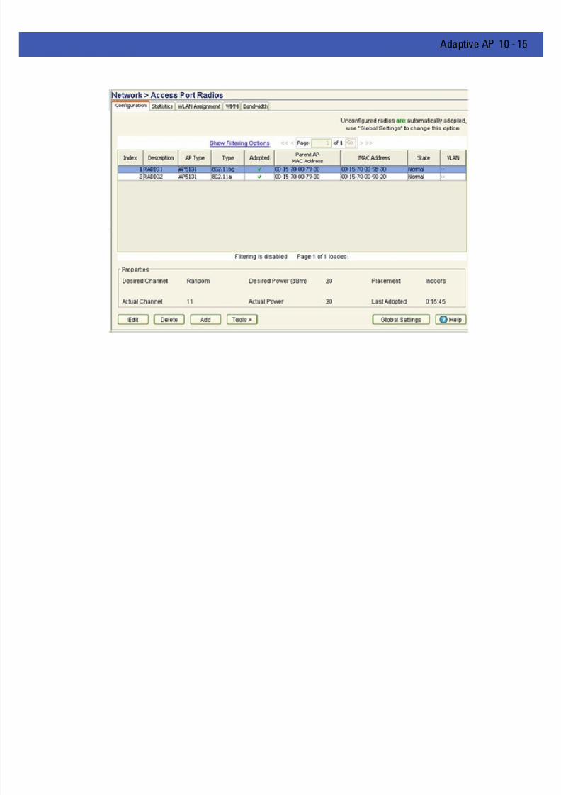
7/18/2019 Motorola AP 5131 Manual
http://slidepdf.com/reader/full/motorola-ap-5131-manual 573/613
Adaptive AP 10 - 15

7/18/2019 Motorola AP 5131 Manual
http://slidepdf.com/reader/full/motorola-ap-5131-manual 574/613
10 - 16 WiNG 4.4 AP-5131 Product Reference Guide
10.4.3 Adaptive AP Deployment Considerations
Before deploying your switch/AAP configuration, refer to the following usage caveats to optimize its effectiveness:
• If deploying the access point as an AAP with a remote layer 3 configuration and the AAP is set for switch auto discovery(primary/standby), the access point will un-adopt from its switch after a few moments. To remedy this problem, ensureLAN1 has 802.1q trunking enabled and the correct management VLAN defined.
• Extended WLANs are mapped to the AP’s LAN2 interface and all independent WLANs are mapped to the AP’s LAN1Interface.
• If deploying multiple independent WLANs mapped to different VLANs, ensure the AP’s LAN1 interface is connected toa trunk port on the L2/L3 switch and appropriate management and native VLANs are configured.
• The WLAN used for mesh backhaul must always be an independent WLAN.
• The switch configures an AAP. If manually changing wireless settings on the AP, they are not updated on the switch.It's a one way configuration, from the switch to the AP.
• An AAP always requires a router between the AP and the switch.
• An AAP can be used behind a NAT.
• An AAP uses UDP port 24576 for control frames and UDP port 24577 for data frames.
• Multiple VLANs per WLAN, L3 mobility, dynamic VLAN assignment, NAC, self healing, rogue AP, MU locationing,hotspot on extended WLAN are some of the important wireless features not supported in an AAP supporteddeployment.

7/18/2019 Motorola AP 5131 Manual
http://slidepdf.com/reader/full/motorola-ap-5131-manual 575/613
Adaptive AP 10 - 17
10.4.4 Sample Switch Configuration File for IPSec and Independent WLAN
The following constitutes a sample RFS7000 switch configuration file supporting an AAP IPSec with Independent WLANconfiguration. Please note new AAP specific CLI commands in red and relevant comments in blue.
The sample output is as follows:
!! configuration of RFS7000 RFS7000-1 version 1.1.0.0-016D!version 1.0!!aaa authentication login default noneservice prompt crash-info!hostname RFS7000-1!
username admin password 1 8e67bb26b358e2ed20fe552ed6fb832f397a507dusername admin privilege superuserusername operator password 1 fe96dd39756ac41b74283a9292652d366d73931f!!To configure the ACL to be used in the CRYPTO MAP!ip access-list extended AAP-ACL permit ip host 10.10.10.250 any rule-precedence 20!spanning-tree mst cisco-interoperability enablespanning-tree mst configname My Name
!country-code uslogging buffered 4logging console 7logging host 157.235.92.97logging syslog 7snmp-server sysname RFS7000-1snmp-server manager v2snmp-server manager v3snmp-server user snmptrap v3 encrypted auth md5 0x7be2cb56f6060226f15974c936e2739bsnmp-server user snmpmanager v3 encrypted auth md5 0x7be2cb56f6060226f15974c936e2739b
snmp-server user snmpoperator v3 encrypted auth md5 0x49c451c7c6893ffcede0491bbd0a12c4!To configure the passkey for a Remote VPN Peer - 255.255.255.255 denotes all AAPs. 12345678 is the default passkey. Ifyou change on the AAP, change here as well. !crypto isakmp key 0 12345678 address 255.255.255.255!ip http serverip http secure-trustpoint default-trustpointip http secure-serverip sshno service pm sys-restart
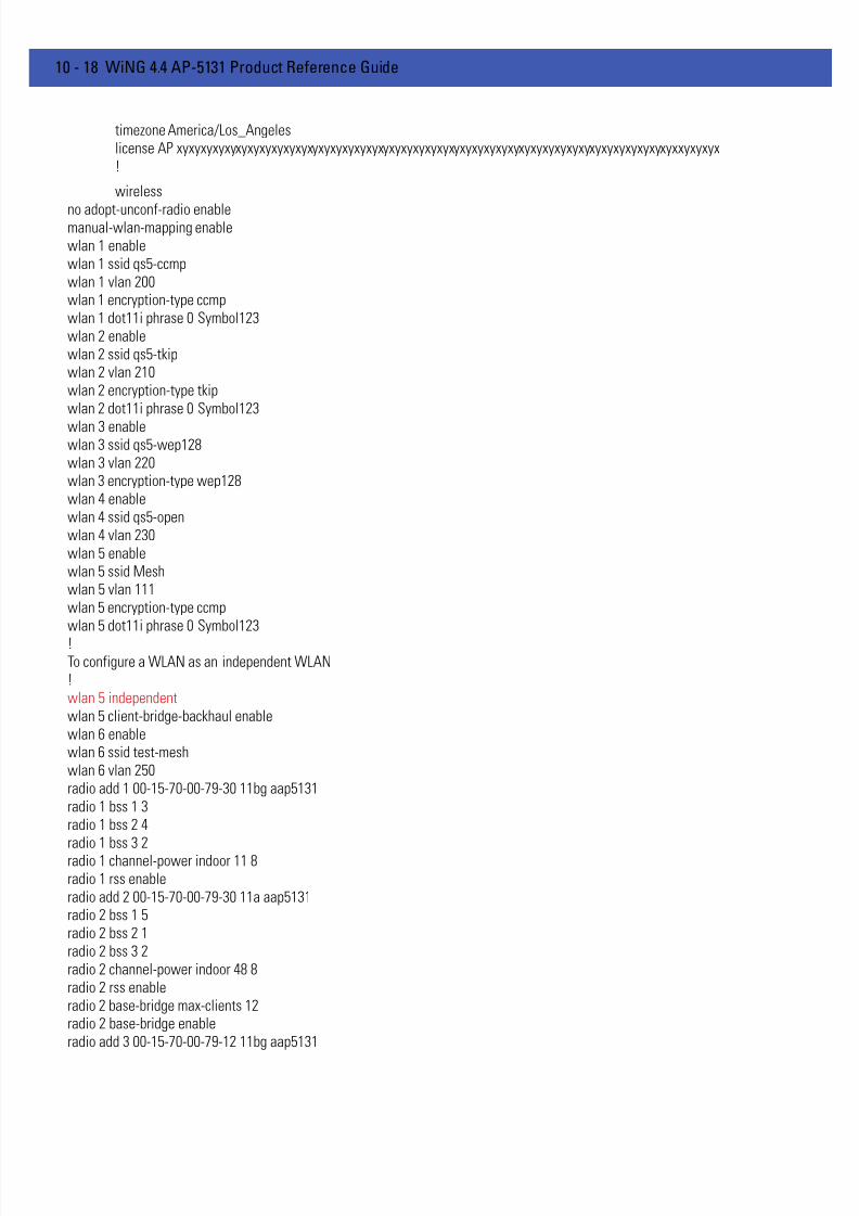
7/18/2019 Motorola AP 5131 Manual
http://slidepdf.com/reader/full/motorola-ap-5131-manual 576/613
10 - 18 WiNG 4.4 AP-5131 Product Reference Guide
timezone America/Los_Angeleslicense AP xyxyxyxyxyxyxyxyxyxyxyxyxyxyxyxyxyxyxyxyxyxyxyxyxyxyxyxyxyxyxyxyxyxyxyxyxyxyxyxyxyxyxxyxyxyx!
wireless
no adopt-unconf-radio enablemanual-wlan-mapping enablewlan 1 enablewlan 1 ssid qs5-ccmpwlan 1 vlan 200wlan 1 encryption-type ccmpwlan 1 dot11i phrase 0 Symbol123wlan 2 enablewlan 2 ssid qs5-tkipwlan 2 vlan 210wlan 2 encryption-type tkipwlan 2 dot11i phrase 0 Symbol123
wlan 3 enablewlan 3 ssid qs5-wep128wlan 3 vlan 220wlan 3 encryption-type wep128wlan 4 enablewlan 4 ssid qs5-openwlan 4 vlan 230wlan 5 enablewlan 5 ssid Meshwlan 5 vlan 111wlan 5 encryption-type ccmpwlan 5 dot11i phrase 0 Symbol123
!To configure a WLAN as an independent WLAN!wlan 5 independentwlan 5 client-bridge-backhaul enablewlan 6 enablewlan 6 ssid test-meshwlan 6 vlan 250radio add 1 00-15-70-00-79-30 11bg aap5131radio 1 bss 1 3radio 1 bss 2 4
radio 1 bss 3 2radio 1 channel-power indoor 11 8radio 1 rss enableradio add 2 00-15-70-00-79-30 11a aap5131radio 2 bss 1 5radio 2 bss 2 1radio 2 bss 3 2radio 2 channel-power indoor 48 8radio 2 rss enableradio 2 base-bridge max-clients 12radio 2 base-bridge enableradio add 3 00-15-70-00-79-12 11bg aap5131
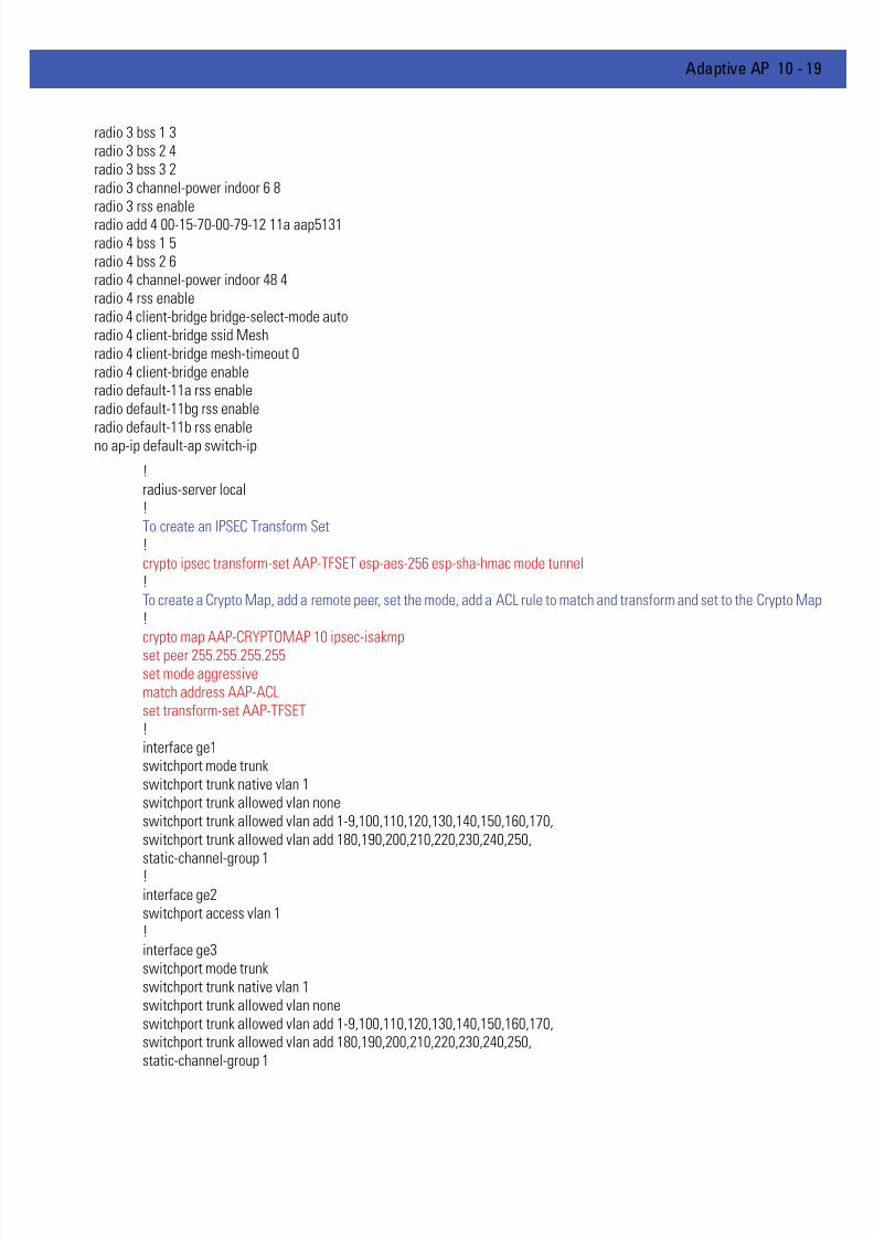
7/18/2019 Motorola AP 5131 Manual
http://slidepdf.com/reader/full/motorola-ap-5131-manual 577/613
Adaptive AP 10 - 19
radio 3 bss 1 3radio 3 bss 2 4radio 3 bss 3 2radio 3 channel-power indoor 6 8radio 3 rss enableradio add 4 00-15-70-00-79-12 11a aap5131radio 4 bss 1 5radio 4 bss 2 6radio 4 channel-power indoor 48 4radio 4 rss enableradio 4 client-bridge bridge-select-mode autoradio 4 client-bridge ssid Meshradio 4 client-bridge mesh-timeout 0radio 4 client-bridge enableradio default-11a rss enableradio default-11bg rss enable
radio default-11b rss enableno ap-ip default-ap switch-ip
!radius-server local!To create an IPSEC Transform Set!crypto ipsec transform-set AAP-TFSET esp-aes-256 esp-sha-hmac mode tunnel!To create a Crypto Map, add a remote peer, set the mode, add a ACL rule to match and transform and set to the Crypto Map!crypto map AAP-CRYPTOMAP 10 ipsec-isakmp
set peer 255.255.255.255set mode aggressivematch address AAP-ACLset transform-set AAP-TFSET!interface ge1switchport mode trunkswitchport trunk native vlan 1switchport trunk allowed vlan noneswitchport trunk allowed vlan add 1-9,100,110,120,130,140,150,160,170,switchport trunk allowed vlan add 180,190,200,210,220,230,240,250,
static-channel-group 1!interface ge2switchport access vlan 1!interface ge3switchport mode trunkswitchport trunk native vlan 1switchport trunk allowed vlan noneswitchport trunk allowed vlan add 1-9,100,110,120,130,140,150,160,170,switchport trunk allowed vlan add 180,190,200,210,220,230,240,250,static-channel-group 1

7/18/2019 Motorola AP 5131 Manual
http://slidepdf.com/reader/full/motorola-ap-5131-manual 578/613
10 - 20 WiNG 4.4 AP-5131 Product Reference Guide
!interface ge4switchport access vlan 1!interface me1ip address dhcp!interface sa1switchport mode trunkswitchport trunk native vlan 1switchport trunk allowed vlan noneswitchport trunk allowed vlan add 1-9,100,110,120,130,140,150,160,170,switchport trunk allowed vlan add 180,190,200,210,220,230,240,250,!!!
!interface vlan1ip address dhcp!To attach a Crypto Map to a VLAN Interface!crypto map AAP-CRYPTOMAP!sole!ip route 157.235.0.0/16 157.235.92.2ip route 172.0.0.0/8 157.235.92.2
!ntp server 10.10.10.100 prefer version 3
line con 0line vty 0 24!end

7/18/2019 Motorola AP 5131 Manual
http://slidepdf.com/reader/full/motorola-ap-5131-manual 579/613
APPENDIX A TECHNICAL SPECIFICATIONS
This appendix provides technical specifications in the following areas:
• Physical Characteristics
• Electrical Characteristics
• Radio Characteristics
• Antenna Specifications
• Country Codes

7/18/2019 Motorola AP 5131 Manual
http://slidepdf.com/reader/full/motorola-ap-5131-manual 580/613
A - 2 WiNG 4.4 AP-5131 Product Reference Guide
A.1 Physical Characteristics
For more information, see:
• AP-5131 Physical Characteristics
• AP-5181 Physical Characteristics
A.1.1 AP-5131 Physical Characteristics
The AP-5131 has the following physical characteristics:
A.1.2 AP-5181 Physical Characteristics
The AP-5181 has the following physical characteristics:
Dimensions 5.32 inches long x 9.45 inches wide x 1.77 inches thick.135 mm long x 240 mm wide x 45 mm thick.
Housing Metal, Plenum Housing (UL2043)
Weight 1.95 lbs/0.88 Kg (single-radio model)
2.05 lbs/0.93 Kg (dual-radio model)
OperatingTemperature
-20 to 50° Celsius
StorageTemperature
-40 to 70° Celsius
Altitude 8,000 feet/2438 m @ 28° Celsius (operating)15,000 feet/4572 m @ 12° Celsius (storage)
Vibration Vibration to withstand .02g²/Hz, random, sine, 20-2k Hz
Humidity 5 to 95% (operating) 5 to 85% (storage)
ElectrostaticDischarge
15kV (air) @ 50% rh8kV (contact) @ 50% rh
Drop Bench drop 36 inches to concrete (excluding side withconnectors)
Dimensions 12 inches long x 8.25 inches wide x 3.5 inches thick.
Housing Aluminum
Weight 4 lbs.
OperatingTemperature
-30 to 55° Celsius
StorageTemperature
-40 to 85° Celsius
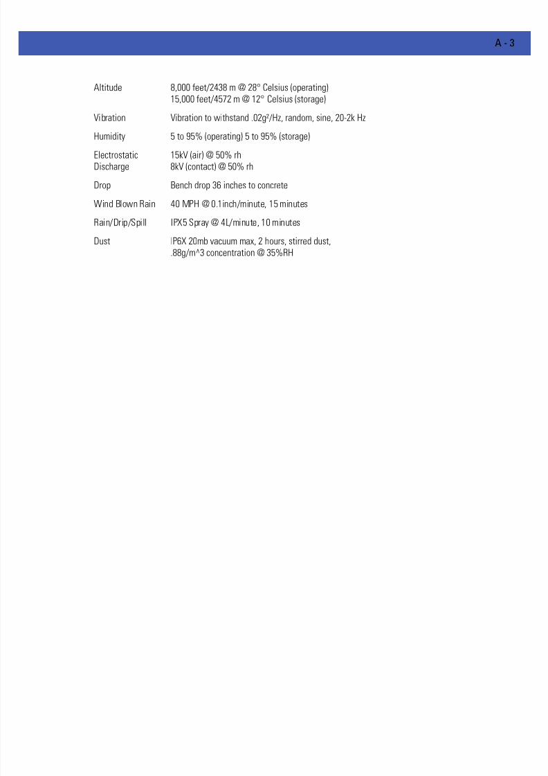
7/18/2019 Motorola AP 5131 Manual
http://slidepdf.com/reader/full/motorola-ap-5131-manual 581/613
A - 3
Altitude 8,000 feet/2438 m @ 28° Celsius (operating)15,000 feet/4572 m @ 12° Celsius (storage)
Vibration Vibration to withstand .02g²/Hz, random, sine, 20-2k Hz
Humidity 5 to 95% (operating) 5 to 95% (storage)
ElectrostaticDischarge
15kV (air) @ 50% rh8kV (contact) @ 50% rh
Drop Bench drop 36 inches to concrete
Wind Blown Rain 40 MPH @ 0.1inch/minute, 15 minutes
Rain/Drip/Spill IPX5 Spray @ 4L/minute, 10 minutes
Dust IP6X 20mb vacuum max, 2 hours, stirred dust,.88g/m^3 concentration @ 35%RH

7/18/2019 Motorola AP 5131 Manual
http://slidepdf.com/reader/full/motorola-ap-5131-manual 582/613
A - 4 WiNG 4.4 AP-5131 Product Reference Guide
A.2 Electrical Characteristics
Both the AP-5131 and the AP-5181 access points have the following electrical characteristics:
CAUTION An AP-5181 model access point cannot use the AP-5131recommended Motorola Solutions 48-Volt Power Supply (Part No. 50-14000-243R). However, Motorola Solutions does recommend the AP-PSBIAS-5181-01R model power supply for use the AP-5181.
Operating Voltage 48Vdc (Nom)
Operating Current 200mA (Peak) @ 48Vdc170mA (Nom) @ 48Vdc
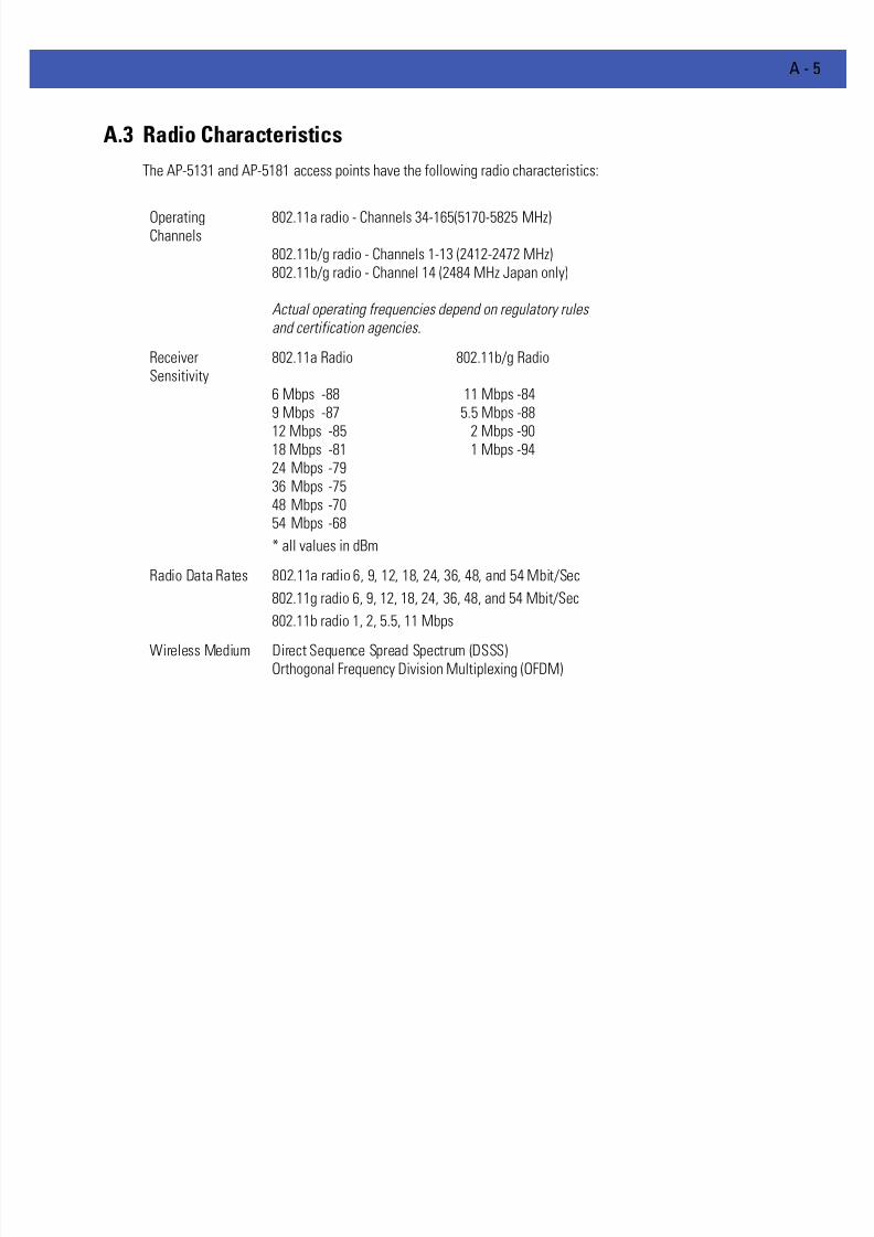
7/18/2019 Motorola AP 5131 Manual
http://slidepdf.com/reader/full/motorola-ap-5131-manual 583/613
A - 5
A.3 Radio Characteristics
The AP-5131 and AP-5181 access points have the following radio characteristics:
OperatingChannels
802.11a radio - Channels 34-165(5170-5825 MHz)
802.11b/g radio - Channels 1-13 (2412-2472 MHz)802.11b/g radio - Channel 14 (2484 MHz Japan only)
Actual operating frequencies depend on regulatory rulesand certification agencies.
ReceiverSensitivity
802.11a Radio 802.11b/g Radio
6 Mbps -88 11 Mbps -849 Mbps -87 5.5 Mbps -88
12 Mbps -85 2 Mbps -9018 Mbps -81 1 Mbps -9424 Mbps -7936 Mbps -7548 Mbps -7054 Mbps -68
* all values in dBm
Radio Data Rates 802.11a radio 6, 9, 12, 18, 24, 36, 48, and 54 Mbit/Sec
802.11g radio 6, 9, 12, 18, 24, 36, 48, and 54 Mbit/Sec
802.11b radio 1, 2, 5.5, 11 Mbps
Wireless Medium Direct Sequence Spread Spectrum (DSSS)Orthogonal Frequency Division Multiplexing (OFDM)
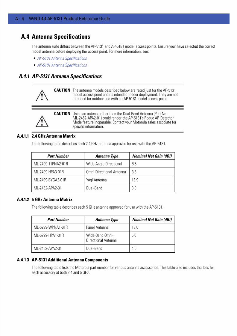
7/18/2019 Motorola AP 5131 Manual
http://slidepdf.com/reader/full/motorola-ap-5131-manual 584/613
A - 6 WiNG 4.4 AP-5131 Product Reference Guide
A.4 Antenna Specifications
The antenna suite differs between the AP-5131 and AP-5181 model access points. Ensure your have selected the correctmodel antenna before deploying the access point. For more information, see:
• AP-5131 Antenna Specifications • AP-5181 Antenna Specifications
A.4.1 AP-5131 Antenna Specifications
A.4.1.1 2.4 GHz Antenna Matrix
The following table describes each 2.4 GHz antenna approved for use with the AP-5131.
A.4.1.2 5 GHz Antenna Matrix
The following table describes each 5 GHz antenna approved for use with the AP-5131.
A.4.1.3 AP-5131 Additional Antenna Components
The following table lists the Motorola part number for various antenna accessories. This table also includes the loss foreach accessory at both 2.4 and 5 GHz.
CAUTION The antenna models described below are rated just for the AP-5131model access point and its intended indoor deployment. They are notintended for outdoor use with an AP-5181 model access point.
CAUTION Using an antenna other than the Dual-Band Antenna (Part No.
ML-2452-APA2-01) could render the AP-5131’s Rogue AP DetectorMode feature inoperable. Contact your Motorola sales associate forspecific information.
Part Number Antenna Type Nominal Net Gain (dBi)
ML-2499-11PNA2-01R Wide Angle Directional 8.5
ML-2499-HPA3-01R Omni-Directional Antenna 3.3
ML-2499-BYGA2-01R Yagi Antenna 13.9
ML-2452-APA2-01 Dual-Band 3.0
Part Number Antenna Type Nominal Net Gain (dBi)
ML-5299-WPNA1-01R Panel Antenna 13.0
ML-5299-HPA1-01R Wide-Band Omni-Directional Antenna
5.0
ML-2452-APA2-01 Dual-Band 4.0

7/18/2019 Motorola AP 5131 Manual
http://slidepdf.com/reader/full/motorola-ap-5131-manual 585/613
A - 7
A.4.1.4 AP-5131 Antenna Accessory Connectors, Cable Type and Length
The following table describes each antenna accessory’s connector and cable type, plus the length.
A.4.2 AP-5181 Antenna Specifications
The AP-5181 2.4 GHz antenna suite includes the following models:
Item Part Number Description Loss (db)@ 2.4 GHz
Loss (db)@ 5 GHz
72PJ ML-1499-72PJ-01R Cable
Extension
2.5
LAK1 ML-1499-LAK1-01R
LightningArrestor+
0.75
LAK2 ML-1499-LAK2-01R
LightningArrestor
0.25
10JK ML-1499-10JK-01R
Jumper Kit 0.75 1.6
25JK ML-1499-25JK-01R
Jumper Kit 1.9 3.5
50JK ML-1499-50JK-01R
Jumper Kit 3.75 6.6
100JK ML-1499-100JK-01R
Jumper Kit 7.5 12.8
Item Connector1 Connector2
Length
(meters) Cable Type 72PJ RPBNC-F RPBNC-M 1.83 RG-58
LAK1 RPBNC-F N-F 0.305 RG-58
LAK2 N-F N-M
10JK N-M N-M 3.05 RG-8
25JK N-M N-M 7.62 RG-8
50JK N-M N-M 15.24 RG-8
100JK N-M N-M 30.48 RG-8
Part Number Antenna Type Nominal Net Gain
(dBi) Description
ML-2499-FHPA5-01R
Omni-DirectionalAntenna
5.0 2.4 GHz,Type N connector,no pigtail
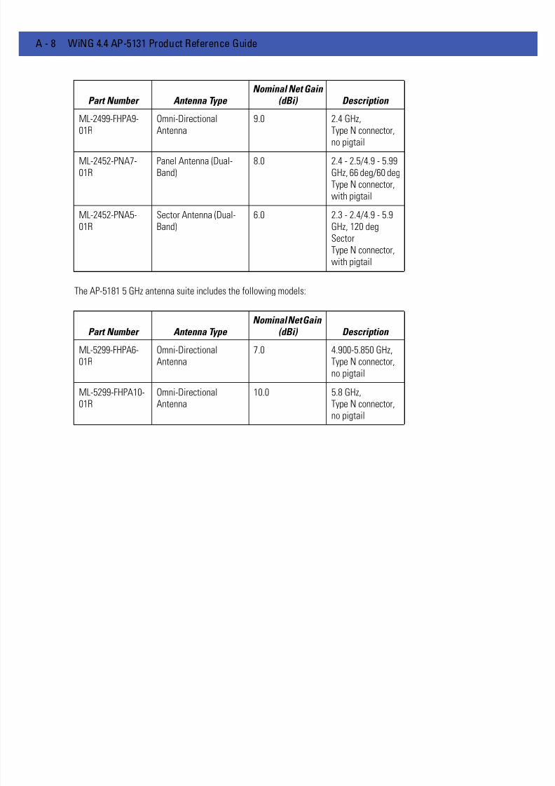
7/18/2019 Motorola AP 5131 Manual
http://slidepdf.com/reader/full/motorola-ap-5131-manual 586/613
A - 8 WiNG 4.4 AP-5131 Product Reference Guide
The AP-5181 5 GHz antenna suite includes the following models:
ML-2499-FHPA9-01R
Omni-DirectionalAntenna
9.0 2.4 GHz,Type N connector,no pigtail
ML-2452-PNA7-01R
Panel Antenna (Dual-Band)
8.0 2.4 - 2.5/4.9 - 5.99GHz, 66 deg/60 degType N connector,with pigtail
ML-2452-PNA5-01R
Sector Antenna (Dual-Band)
6.0 2.3 - 2.4/4.9 - 5.9GHz, 120 degSectorType N connector,with pigtail
Part Number Antenna Type Nominal Net Gain
(dBi) Description
ML-5299-FHPA6-01R
Omni-DirectionalAntenna
7.0 4.900-5.850 GHz,Type N connector,no pigtail
ML-5299-FHPA10-01R
Omni-DirectionalAntenna
10.0 5.8 GHz,Type N connector,
no pigtail
Part Number Antenna Type Nominal Net Gain
(dBi) Description
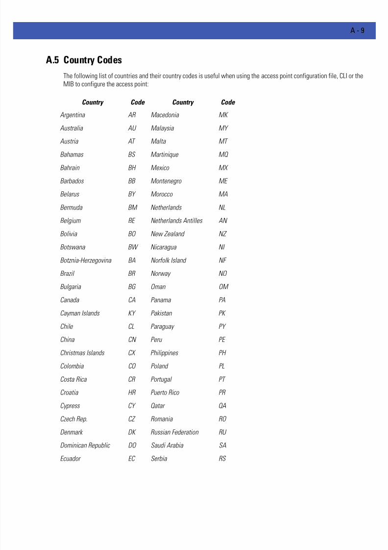
7/18/2019 Motorola AP 5131 Manual
http://slidepdf.com/reader/full/motorola-ap-5131-manual 587/613
A - 9
A.5 Country Codes
The following list of countries and their country codes is useful when using the access point configuration file, CLI or theMIB to configure the access point:
Country Code Country Code
Argentina AR Macedonia MK
Australia AU Malaysia MY
Austria AT Malta MT
Bahamas BS Martinique MQ
Bahrain BH Mexico MX
Barbados BB Montenegro ME
Belarus BY Morocco MA
Bermuda BM Netherlands NL
Belgium BE Netherlands Antilles AN
Bolivia BO New Zealand NZ
Botswana BW Nicaragua NI
Botznia-Herzegovina BA Norfolk Island NF
Brazil BR Norway NO
Bulgaria BG Oman OM
Canada CA Panama PA
Cayman Islands KY Pakistan PK
Chile CL Paraguay PY
China CN Peru PE
Christmas Islands CX Philippines PH
Colombia CO Poland PL
Costa Rica CR Portugal PT
Croatia HR Puerto Rico PR
Cypress CY Qatar QA
Czech Rep. CZ Romania RO
Denmark DK Russian Federation RU
Dominican Republic DO Saudi Arabia SA
Ecuador EC Serbia RS

7/18/2019 Motorola AP 5131 Manual
http://slidepdf.com/reader/full/motorola-ap-5131-manual 588/613
A - 10 WiNG 4.4 AP-5131 Product Reference Guide
El Salvador SV Singapore SG
Estonia EE Slovak Republic SK
Egypt EG Slovenia SI
Falkland Islands FK South Africa ZA
Finland FI South Korea KR
France FR Spain ES
Germany DE Sri Lanka LK
Greece GR Sweden SE
Guam GU Switzerland CH
Guatemala GT Taiwan TW
Guinea GN Thailand TH
Haiti HT Trinidad and Tobago TT
Honduras HN Turkey TR
Hong Kong HK Ukraine UA
Hungary HU UAE AE
Iceland IS United Kingdom UK
India IN USA US
Indonesia ID Uruguay UY
Ireland IE Virgin Islands (British) VG
Israel IL Virgin Islands (US) VI
Italy IT Vietnam VN
Jamaica JM Venezuela VE
Japan JP
Jordan JO
Kazakhstan KZ
Kuwait KW
Latvia LV
Lebanon LB
Liechtenstein LI
Lithuania LT
Luxembourg LU
7/18/2019 Motorola AP 5131 Manual
http://slidepdf.com/reader/full/motorola-ap-5131-manual 589/613
APPENDIX B USAGE SCENARIOS
This appendix provides practical usage scenarios for many of the access point’s key features. This information should bereferenced as a supplement to the information contained within this Product Reference Guide.
The following scenarios are described:
• Configuring Automatic Updates using a DHCP or Linux BootP Server
• Configuring an IPSEC Tunnel and VPN FAQs

7/18/2019 Motorola AP 5131 Manual
http://slidepdf.com/reader/full/motorola-ap-5131-manual 590/613
B - 2 WiNG 4.4 AP-5131 Product Reference Guide
B.1 Configuring Automatic Updates using a DHCP or Linux BootP Server
This section provides specific details for configuring either a DHCP or Linux BootP Server to send firmware or configurationfile updates to an access point.
The AutoUpdate feature updates the access point firmware and/or configuration automatically when the access point isreset or does a DHCP request. The update process is conducted over the LAN or WAN port depending on which serverresponds first to the access point’s request for an automatic update.
The firmware is automatically updated each time firmware versions are found to be different between what is running onthe access point and the firmware file that resides on the server. The configuration file is automatically applied when theconfiguration filename is found to be different between what resides on the access point and the filename residing on theserver or when the configuration version is found to be different between what resides on the access point and theconfiguration version residing on the server.
The configuration version can be modified in the text file to cause the configuration to be applied when required. Theparameter name in the file is "cfg-version-1.1-01". The access point only checks the two characters after the third hyphen(01) when making a comparison. Change the last two characters to update the configuration. The two characters can be
alpha-numeric..
B.1.1 Windows - DHCP Server Configuration
See the following sections for information on these DHCP server configurations in the Windows environment:
• Embedded Options - Using Option 43
• Global Options - Using Extended/Standard Options • DHCP Priorities
B.1.1.1 Embedded Options - Using Option 43
This section provides instructions for automatic update of firmware and configuration file via DHCP using extended optionsor standard options configured globally.
The setup example described in this section includes:
• 1 AP-5131 or AP-5181 model access point
• 1 Microsoft Windows DHCP Server
• 1 TFTP Server
Note the following caveats regarding this procedure before beginning:
• Ensure the LAN Interface is configured as a DHCP Client
• If the existing and update firmware files are the same, the firmware will not get updated.
To configure the DHCP Server for automatic updates:
1. Set the Windows DHCP Server and access point on the same Ethernet segment.
2. Configure the Windows based DHCP Server as follows:
c. Highlight the Server Domain Name (for example, apfw.motorola.com). From the Action menu, select Define VendorClasses.
NOTE A Motorola AP-5181 model access point does not support firmware priorto version 1.1.1.x.

7/18/2019 Motorola AP 5131 Manual
http://slidepdf.com/reader/full/motorola-ap-5131-manual 591/613
B - 3
d. Create a new vendor class. For example, AP51xx Options.
e. Enter the vendor class Identifier MotorolaAP.51xx-V1-1-1 . Enter the value in ASCII format, the server converts it to hexautomatically. Use the chart below to determine which vendor class ID to use based on the firmware.
f. From the Action menu, select Set Predefined Options.
g. Add the following 3 new options under AP51xx Options class:
h. Highlight Scope Options from the tree and select Configure Options.
i. Go to the Advanced tab. From under the Vendor Class AP51xx Options, check all three options mentioned in the tableabove and enter a value for each option.
3. Copy the firmware and configuration files to the appropriate directory on the TFTP Server.
4. Restart the access point.
5. While the access point boots, verify the access point:
• Obtains and applies the expected IP Address from the DHCP Server
• Downloads both the firmware and configuration files from the TFTP Server and updates both as needed. Verify thefile versions within the System Settings screen.
B.1.1.2 Global Options - Using Extended/Standard Options
The following are instructions for automatic firmware and configuration file updates via DHCP using extended options orstandard options configured globally.
The setup example described in this section includes:
• 1 AP-5131 or AP-5181 model access point
• 1 Microsoft Windows DHCP Server
• 1 TFTP Server.
To configure Global options using extended/standard options:
1. Set the Windows DHCP Server and access point on the same Ethernet segment.
2. Configure the Windows based DHCP Server as follows:
AP Firmware Vendor Class ID
1.1 (or older) SymbolAP.5131-V1-1
1.1.1.x SymbolAP.51xx-V1-1-1
1.1.2.x MotorolaAP.51xx-V1-1-2
2.0 MotorolaAP.51xx-V2-0-0
Code Data type
Access point TFTP Server IP Address
(Note: Use any one option)
181
186
IP address
String
Access point Firmware File Name 187 String
Access point Config File Name
(Note: Use any one option)
129
188
String
String
NOTE If the firmware files are the same, the firmware will not get updated. Ifthe configuration file name matches the last used configuration file on theaccess point or if the configuration file versions are the same, the accesspoint configuration will not get updated.
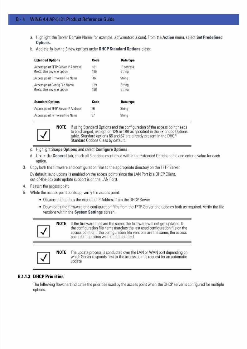
7/18/2019 Motorola AP 5131 Manual
http://slidepdf.com/reader/full/motorola-ap-5131-manual 592/613
B - 4 WiNG 4.4 AP-5131 Product Reference Guide
a. Highlight the Server Domain Name (for example, apfw.motorola.com). From the Action menu, select Set PredefinedOptions.
b. Add the following 3 new options under DHCP Standard Options class:
c. Highlight Scope Options and select Configure Options.
d. Under the General tab, check all 3 options mentioned within the Extended Options table and enter a value for eachoption.
3. Copy both the firmware and configuration files to the appropriate directory on the TFTP Server.
By default, auto update is enabled on the access point (since the LAN Port is a DHCP Client,out-of-the-box auto update support is on the LAN Port).
4. Restart the access point.
5. While the access point boots up, verify the access point:
• Obtains and applies the expected IP Address from the DHCP Server
• Downloads the firmware and configuration files from the TFTP Server and updates both as required. Verify the fileversions within the System Settings screen.
B.1.1.3 DHCP Priorities
The following flowchart indicates the priorities used by the access point when the DHCP server is configured for multipleoptions.
Extended Options Code Data type
Access point TFTP Server IP Address
(Note: Use any one option)
181
186
IP address
String
Access point Firmware File Name 187 String
Access point Config File Name
(Note: Use any one option)
129
188
String
String
Standard Options Code Data type
Access point TFTP Server IP Address 66 String
Access point Firmware File Name 67 String
NOTE If using Standard Options and the configuration of the access point needsto be changed, use option 129 or 188 as specified in the Extended Optionstable. Standard options 66 and 67 are already present in the DHCPStandard Options Class by default.
NOTE If the firmware files are the same, the firmware will not get updated. Ifthe configuration file name matches the last used configuration file on theaccess point or if the configuration file versions are the same, the accesspoint configuration will not get updated.
NOTE The update process is conducted over the LAN or WAN port depending onwhich Server responds first to the access point’s request for an automaticupdate.

7/18/2019 Motorola AP 5131 Manual
http://slidepdf.com/reader/full/motorola-ap-5131-manual 593/613
B - 5
If the DHCP Server is configured for options 186 and 66 (to assign TFTP Server IP addresses) theaccess point uses the IP address configured for option 186. Similarly, if the DHCP Server is configured for options 187 and67 (for the firmware file) the access point uses the file name configured for option 187. If the DHCP Server is configuredfor embedded and global options, the embedded options take precedence.
B.1.2 Linux - BootP Server Configuration
See the following sections for information on these BootP server configurations in the Linux environment:
• BootP Options
• BootP Priorities
B.1.2.1 BootP Options
This section contains instructions for the automatic update of the access point firmware and configuration file using aBootP Server.
The setup example described in this section includes:
• 1 AP-5131 or AP-5181 model access point
• 1 Linux/Unix BOOTP Server
• 1 TFTP Server.
To configure BootP options using a Linux/Unix BootP Server:
1. Set the Linux/Unix BootP Server and access point on the same Ethernet segment.
2. Configure the bootptab file (/etc/bootptab) on the Linux/Unix BootP Server in any one of the formats that follows:
Using options 186, 187 and 188:
--------------------------------------------------------------------------------------------

7/18/2019 Motorola AP 5131 Manual
http://slidepdf.com/reader/full/motorola-ap-5131-manual 594/613
B - 6 WiNG 4.4 AP-5131 Product Reference Guide
Using options 66, 67 and 129:
Using options sa, bf and 136:
3. Copy the firmware and configuration files to the appropriate directory on the TFTP Server.
By default, auto update is enabled on the access point (since the LAN Port is a DHCP Client,out-of-the-box auto update support is on the LAN Port).
4. Restart the access point.
5. While the access point boots, verify the access point:
• Sends a true BootP request.
• Obtains and applies the expected IP Address from the BootP Server.
• Downloads both the firmware and configuration files from the TFTP Server and updates them as required. Verify thefile versions within the System Settings screen.
Whenever a configuration file is specified, the access point will tftp the config file, parse it and use the firmware file namein the config file.
If T136 is provided by the server, the access point strips off the TFTP root directory from the fully qualified configuration filename to obtain a relative file name. For example, if usingbf=/opt/tftpdir/ftp/dist/ap.cfg and T136="/opt/tftpdir", the config file name is
NOTE The bf option prefixes a forward slash (/) to the configuration file name.The forward slash may not be supported on Windows based TFTP Servers.
A P -5 1 3 1 : h a = 0 0 a 0 f8 8 a a 6 d 8 \ < L A N M A C A d d re s s >
: sm=255.255 .255 .0 \ < S u b n e t M a s k >
:i p=15 7 .235 .93 .128 \ < IP A ddress>
:g w = 1 5 7 . 2 3 5 .9 3 . 2 \ < g a te w a y >:T1 86=”1 57.235 .93 .250” \ <TFTP Server I P>
:T187="apfw.b in" \ <F i rmware f i l e>
: T188="cfg . tx t " : <Con f igu rat ion f il e>
AP-5131 :ha=00a0f88aa6d8 \ < L A N M A C A d d r e s s>
: sm=255 .255 .255 .0 \ < S u b n e t Ma s k >
: ip=157.235.93.128\ < IP Add ress>
:gw=157 .235 .93 .2 \ <ga teway>
:T66=”157 .235 .93 .250” \ <TFTP Serve r IP>
:T67="apfw.bin" \ <F i rmware f i le>: T 12 9 = " cf . tx t ": < C o n fi u r a ti o n f il e >
AP-5131:ha=00a0f88aa6d8\ < LAN M AC Address>
:sm=255.255.255.0\ <Subnet Mask>
:ip=157.235.93.128\ <IP Address>
:gw=157.235.93.2\ <gateway>
:sa=157.235.93.250\ <TFTP Server IP>
:bf=/tftpboot/cfg.txt\ <Configuration file>
:T136=”/tftpboot/”: <TFTP root directory>
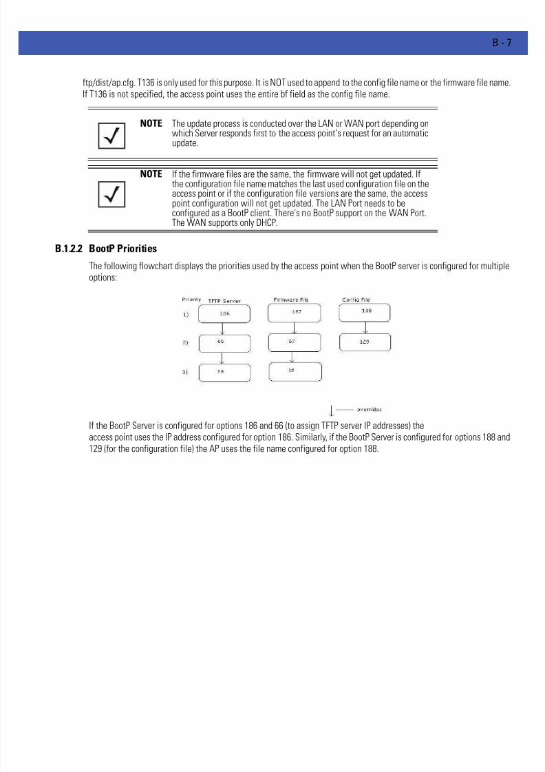
7/18/2019 Motorola AP 5131 Manual
http://slidepdf.com/reader/full/motorola-ap-5131-manual 595/613
B - 7
ftp/dist/ap.cfg. T136 is only used for this purpose. It is NOT used to append to the config file name or the firmware file name.If T136 is not specified, the access point uses the entire bf field as the config file name.
B.1.2.2 BootP Priorities
The following flowchart displays the priorities used by the access point when the BootP server is configured for multipleoptions:
If the BootP Server is configured for options 186 and 66 (to assign TFTP server IP addresses) theaccess point uses the IP address configured for option 186. Similarly, if the BootP Server is configured for options 188 and129 (for the configuration file) the AP uses the file name configured for option 188.
NOTE The update process is conducted over the LAN or WAN port depending on
which Server responds first to the access point’s request for an automaticupdate.
NOTE If the firmware files are the same, the firmware will not get updated. Ifthe configuration file name matches the last used configuration file on theaccess point or if the configuration file versions are the same, the accesspoint configuration will not get updated. The LAN Port needs to beconfigured as a BootP client. There's no BootP support on the WAN Port.The WAN supports only DHCP.

7/18/2019 Motorola AP 5131 Manual
http://slidepdf.com/reader/full/motorola-ap-5131-manual 596/613
B - 8 WiNG 4.4 AP-5131 Product Reference Guide
B.2 Configuring an IPSEC Tunnel and VPN FAQs
The access point has the capability to create a tunnel between an access point and a VPN endpoint. The access point canalso create a tunnel from one access point to another access point.
The following instruction assumes the reader is familiar with basic IPSEC and VPN terminology and technology.• Configuring a VPN Tunnel Between Two Access Points
• Configuring a Cisco VPN Device
• Frequently Asked VPN Questions
B.2.1 Configuring a VPN Tunnel Between Two Access Points
The access point can connect to a non-AP device supporting IPSec, such as a Cisco VPN device - labeled as "Device #2".
For this usage scenario, the following components are required:
• 2 access points (either an AP-5131 or AP-5181 model)
• 1 PC on each side of the access point’s LAN.
To configure a VPN tunnel between two access points:
1. Ensure the WAN ports are connected via the internet.
2. On access point #1, select WAN -> VPN from the main menu tree.
3. Click Add to add the tunnel to the list.
4. Enter a tunnel name (tunnel names do not need to match).
5. Enter the WAN port IP address of AP #1 for the Local WAN IP.
6. Within the Remote Subnet and Remote Subnet Mask fields, enter the LAN IP subnet and mask of AP #2 /Device #2.
7. Enter the WAN port IP address of AP #2/ Device #2 for a Remote Gateway.
8. Click Apply to save the changes.

7/18/2019 Motorola AP 5131 Manual
http://slidepdf.com/reader/full/motorola-ap-5131-manual 597/613
B - 9
9. Select the Auto (IKE) Key Exchange radio button.
10. Select the Auto Key Settings button.
11. For the ESP Type, select ESP with Authentication and use AES 128-bit as the ESP encryption algorithm and MD5 as theauthentication algorithm. Click OK.
12. Select the IKE Settings button.
13. Select Pre Shared Key (PSK) from the IKE Authentication Mode drop-down menu.
14. Enter a Passphrase. Passphrases must match on both VPN devices.
15. Select AES 128-bit as the IKE Encryption Algorithm.
NOTE For this example, Auto IKE Key Exchange is used. Any key exchange canbe used, depending on the security needed, as long as both devices oneach end of the tunnel are configured exactly the same.
NOTE Ensure the IKE authentication Passphrase is the same as the Pre-sharedkey on the Cisco PIX device.

7/18/2019 Motorola AP 5131 Manual
http://slidepdf.com/reader/full/motorola-ap-5131-manual 598/613
B - 10 WiNG 4.4 AP-5131 Product Reference Guide
16. Select Group 2 as the Diffie -Hellman Group. Click OK. This will take you back to the VPN screen.
17. Click Apply to make the changes
18. Check the VPN Status screen. Notice the status displays "NOT_ACTIVE". This screen automatically refreshes to get thecurrent status of the VPN tunnel. Once the tunnel is active, the IKE_STATE changes from NOT_CONNECTED to SA_MATURE.
19. On access point #2/ Device #2, repeat the same procedure. However, replace access point #2 information with access point #1 information.
20. Once both tunnels are established, ping each side of the tunnel to ensure connectivity.
B.2.2 Configuring a Cisco VPN Device
This section includes general instructions for configuring a Cisco PIX Firewall 506 series device.
For the usage scenario described in this section, you will require the following:
• 1 Cisco VPN device
• 1 PC connected to the LAN side of the access point and the Cisco PIX.
Below is how the access point VPN Status screen should look if the entire configuration is setup correctly once the VPNtunnel is active. The status field should display "ACTIVE".
B.2.3 Frequently Asked VPN Questions
The following are common questions that arise when configuring a VPN tunnel.
• Question 1: Does the access point IPSec tunnel support multiple subnets on the other end of a VPNconcentrator?
Yes. The access point can access multiple subnets on the other end of the VPN Concentrator from the access point's LocalLAN Subnet by:
• Creating multiple VPN Tunnels. The AP supports a maximum of 25 tunnels.
• When using the Remote Subnet IP Address with an appropriate subnet mask, the AP can access multiple subnets
NOTE The Cisco PIX device configuration should match the access point VPNconfiguration in terms of Local WAN IP (PIX WAN), Remote WANGateway (access point WAN IP), Remote Subnet (access point LANSubnet), and the Remote Subnet Mask. The Auto Key Settings and the IKESettings on the Cisco PIX should match the access point Key andIKE settings.

7/18/2019 Motorola AP 5131 Manual
http://slidepdf.com/reader/full/motorola-ap-5131-manual 599/613
B - 11
on the remote end.
For example: If creating a tunnel using 192.168.0.0/16 for the Remote Subnet IP address, the following subnets could beaccessed:
192.168.1.x
192.168.2.x
192.168.3.x, etc
• Question 2: Even if a wildcard entry of "0.0.0.0" is entered in the Remote Subnet field in the VPNconfiguration page, can the AP access multiple subnets on the other end of a VPN concentrator for the APsLAN/WAN side?
No. Using a "0.0.0.0" wildcard is an unsupported configuration. In order to access multiple subnets, the steps in Question #1 must be followed.
• Question 3: Can the AP be accessed via its LAN interface of AP#1 from the local subnet of AP#2 and viceversa?
Yes.
• Question 4: Will the default "Manual Key Exchange" settings work without making any changes?
No. Changes need to be made. Enter Inbound and Outbound ESP Encryption keys on both APs. Each one should be of 16 Hexcharacters (depending on the encryption or authentication scheme used). The VPN tunnel can be established only whenthese corresponding keys match. Ensure the Inbound/Outbound SPI and ESP Authentication Keys have been properlyspecified.
• Question 5: Can a tunnel between an AP-5131 and WS2000 be established?
Yes.
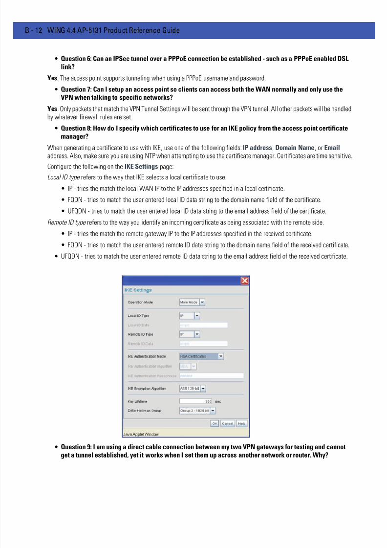
7/18/2019 Motorola AP 5131 Manual
http://slidepdf.com/reader/full/motorola-ap-5131-manual 600/613
B - 12 WiNG 4.4 AP-5131 Product Reference Guide
• Question 6: Can an IPSec tunnel over a PPPoE connection be established - such as a PPPoE enabled DSLlink?
Yes. The access point supports tunneling when using a PPPoE username and password.
• Question 7: Can I setup an access point so clients can access both the WAN normally and only use the
VPN when talking to specific networks?
Yes. Only packets that match the VPN Tunnel Settings will be sent through the VPN tunnel. All other packets will be handledby whatever firewall rules are set.
• Question 8: How do I specify which certificates to use for an IKE policy from the access point certificatemanager?
When generating a certificate to use with IKE, use one of the following fields: IP address, Domain Name, or Emailaddress. Also, make sure you are using NTP when attempting to use the certificate manager. Certificates are time sensitive.
Configure the following on the IKE Settings page:
Local ID type refers to the way that IKE selects a local certificate to use.
• IP - tries the match the local WAN IP to the IP addresses specified in a local certificate.• FQDN - tries to match the user entered local ID data string to the domain name field of the certificate.
• UFQDN - tries to match the user entered local ID data string to the email address field of the certificate.
Remote ID type refers to the way you identify an incoming certificate as being associated with the remote side.
• IP - tries the match the remote gateway IP to the IP addresses specified in the received certificate.
• FQDN - tries to match the user entered remote ID data string to the domain name field of the received certificate.
• UFQDN - tries to match the user entered remote ID data string to the email address field of the received certificate.
• Question 9: I am using a direct cable connection between my two VPN gateways for testing and cannotget a tunnel established, yet it works when I set them up across another network or router. Why?

7/18/2019 Motorola AP 5131 Manual
http://slidepdf.com/reader/full/motorola-ap-5131-manual 601/613
B - 13
The packet processing architecture of the access point VPN solution requires the WAN default gateway to work properly.When connecting two gateways directly, you don't need a default gateway when the two addresses are on the same subnet.As a workaround, point the access point's WAN default gateway to be the other VPN gateway and vice-versa.
• Question 10: I have setup my tunnel and the status still says 'Not Connected'. What should I do now?
VPN tunnels are negotiated on an "as-needed" basis. If you have not sent any traffic between the two subnets, the tunnelwill not get established. Once a packet is sent between the two subnets, the VPN tunnel setup occurs.
• Question 11: I still can't get my tunnel to work after attempting to initiate traffic between the two subnets. What now?
Try the following troubleshooting tips:
• Verify you can ping each of the remote Gateway IP addresses from clients on either side. Failed pings can indicategeneral network connection problems.
• Pinging the internal gateway address of the remote subnet should run the ping through the tunnel as well. Allowingyou to test, even if there are no clients on the remote end.
• Try re-setting the shared secret password on the access point.
• Question 12: My tunnel works fine when I use the LAN-WAN Access page to configure my firewall. Now that I use Advanced LAN Access, my VPN stops working. What am I doing wrong?
VPN requires certain packets to be passed through the firewall. Subnet Access automatically inserts these rules for youwhen you do VPN. Advanced Subnet Access requires these rules to be in effect for each tunnel.
• An 'allow' inbound rule.
• An 'allow' outbound rule.
• For IKE, an 'allow' inbound rule.
Scr <Remote Subnet IP range>
Dst <Local Subnet IP range>
Transport ANY
Scr port 1:65535
Dst port 1:65535
Rev NAT None
Scr <Local Subnet IP range>
Dst <Remote Subnet IP range>
Transport ANY
Scr port 1:65535
Dst port 1:65535
NAT None
Scr <Remote Subnet IP range>
Dst <WAN IP address>
Transport UDP
Scr port 1:65535
Dst port 500

7/18/2019 Motorola AP 5131 Manual
http://slidepdf.com/reader/full/motorola-ap-5131-manual 602/613
B - 14 WiNG 4.4 AP-5131 Product Reference Guide
These three rules should be configured above all other rules (default or user defined). When Advanced LAN Access is used,certain inbound/outbound rules need to be configured to control incoming/outgoing packet flow for IPSec to work properly(with Advanced LAN Access). These rules should be configured first before other rules are configured.
• Question 13: Do I need to add any special routes on the access point to get my VPN tunnel to work?
No. However, clients could need extra routing information. Clients on the local LAN side should either use the access pointas their gateway or have a route entry tell them to use the access point as the gateway to reach the remote subnet.
Rev NAT None

7/18/2019 Motorola AP 5131 Manual
http://slidepdf.com/reader/full/motorola-ap-5131-manual 603/613
B - 15
B.3 Replacing an AP-4131 with an AP-5131 or AP-5181
The access point’s modified default configuration enables an AP-5131or AP-5181 to not only operate in a single-cellenvironment, but also function as a replacement for legacy AP-4131 model access points. You cannot port an AP-4131’sconfiguration file to an AP-5131 or AP-5181, but you can configure an AP-5131 or AP-5181 similarly and provide animproved data rate and feature set.
An AP-4131 has only one LAN port and it is defaulted to DHCP/BOOTP enabled. The AP-5131 andAP-5181 are optimized for single-cell deployment, so the customer to use either as a ”drop-in” replacement for an existingAP-4131 deployment. However, to optimally serve as a replacement for existing AP-4131 deployments, an AP-5131 andAP-5181’s “out-of-box” defaults are now set as follows:
• The LAN1 port must default to DHCP client mode
• The LAN2 port must default to DHCP server mode
• The WAN port must default to Static mode.
• The default gateway now defaults to LAN1.
• The interface parameter has been removed from the Auto Update configuration feature.
• The WAN interface now has http/telnet/https/ssh connectivity enabled by default.

7/18/2019 Motorola AP 5131 Manual
http://slidepdf.com/reader/full/motorola-ap-5131-manual 604/613
B - 16 WiNG 4.4 AP-5131 Product Reference Guide

7/18/2019 Motorola AP 5131 Manual
http://slidepdf.com/reader/full/motorola-ap-5131-manual 605/613
APPENDIX C CUSTOMER SUPPORT
Comprehensive on-line support is available at the Support Central site athttp://www.symbol.com/support/ . Support Central provides our customers with a wealth of information and onlineassistance including developer tools, software downloads, product manuals and online repair requests.
When contacting the Motorola Solutions Support Center, please provide the following information:
•serial number of unit
•model number or product name
•software type and version number.

7/18/2019 Motorola AP 5131 Manual
http://slidepdf.com/reader/full/motorola-ap-5131-manual 606/613
C - 2 WiNG 4.4 AP-5131 Product Reference Guide
C.0.0.0.1 North American Contacts
Support (for warranty and service information):
telephone: 1-800-653-5350
fax: (631) 738-5410Email: [email protected]
C.0.0.0.2 International Contacts
Outside North America:
Motorola Solutions, inc.
Symbol Place
Winnersh Triangle, Berkshire, RG41 5TP
United Kingdom
0800-328-2424 (Inside UK)
+44 118 945 7529 (Outside UK)

7/18/2019 Motorola AP 5131 Manual
http://slidepdf.com/reader/full/motorola-ap-5131-manual 607/613
C - 3
C.0.0.0.3 Web Support Sites
Product Downloads
http://support.symbol.com/support/product/softwaredownloads.do
Manualshttp://support.symbol.com/support/product/manuals.do
C.0.0.0.4 Additional Information
Obtain additional information by contacting Motorola Solutions at:
1-800-722-6234, inside North America
+1-516-738-5200, in/outside North America
http://www.motorola.com/

7/18/2019 Motorola AP 5131 Manual
http://slidepdf.com/reader/full/motorola-ap-5131-manual 608/613
C - 4 WiNG 4.4 AP-5131 Product Reference Guide
7/18/2019 Motorola AP 5131 Manual
http://slidepdf.com/reader/full/motorola-ap-5131-manual 609/613
INDEX
Numerics2.4 GHz antennas. . . . . . . . . . . . . . . . . . . . . . . . . . . . . . . . . . . . . . . . . . . . .A-6
32735
Heading 2
1.1.11 Symbol NetVision Phone/Spectralink Voice Prioritization1-
11
Aaccess options . . . . . . . . . . . . . . . . . . . . . . . . . . . . . . . . . . . . . . . . . . . . . . 1-18
Access Point
CAM . . . . . . . . . . . . . . . . . . . . . . . . . . . . . . . . . . . . . . . . . . . . . . . . . 1-11
encryption . . . . . . . . . . . . . . . . . . . . . . . . . . . . . . . . . . . . . . . . . . . . . . 1-8
PSP . . . . . . . . . . . . . . . . . . . . . . . . . . . . . . . . . . . . . . . . . . . . . . . . . . 1-11
RSSI. . . . . . . . . . . . . . . . . . . . . . . . . . . . . . . . . . . . . . . . . . . . . . . . . . 1-17administrator access . . . . . . . . . . . . . . . . . . . . . . . . . . . . . . . . . . . . . . . . . 4-10
antenna support . . . . . . . . . . . . . . . . . . . . . . . . . . . . . . . . . . . . . . . . . . . . . . 1-5
antenna, 2.4 GHz . . . . . . . . . . . . . . . . . . . . . . . . . . . . . . . . . . . . . . . . . . . . .A-6
AP-5131 access . . . . . . . . . . . . . . . . . . . . . . . . . . . . . . . . . . . . . . . . . . . . . . 4-8
AP-5131 Features. . . . . . . . . . . . . . . . . . . . . . . . . . . . . . . . . . . . . . . . . . . . . 1-4
AP-5131 Firmware . . . . . . . . . . . . . . . . . . . . . . . . . . . . . . . . . . . . . . . . . . . 1-10
AP-5131 management options . . . . . . . . . . . . . . . . . . . . . . . . . . . . . . . . . . 1-9
AP-5131 operating modes . . . . . . . . . . . . . . . . . . . . . . . . . . . . . . . . . . . . . 1-17
AP-5131 placement . . . . . . . . . . . . . . . . . . . . . . . . . . . . . . . . . . . . . . . . . . . 2-6
AP-5131 statistical displays . . . . . . . . . . . . . . . . . . . . . . . . . . . . . . . . . . . 1-11
AP-5131 version . . . . . . . . . . . . . . . . . . . . . . . . . . . . . . . . . . . . . . . . . . . . . . 4-4
AP-5131-13040-WW . . . . . . . . . . . . . . . . . . . . . . . . . . . . . . . . . . . . . . 2-3, 2-4
AP-5131-13041-WW . . . . . . . . . . . . . . . . . . . . . . . . . . . . . . . . . . . . . . . . . . 2-3
AP-5131-13042-WW . . . . . . . . . . . . . . . . . . . . . . . . . . . . . . . . . . . . . . . . . . 2-3AP-5131-13043-WW . . . . . . . . . . . . . . . . . . . . . . . . . . . . . . . . . . . . . . . . . . 2-3
AP-5131-40020-WW . . . . . . . . . . . . . . . . . . . . . . . . . . . . . . . . . . . . . . . . . . 2-3
AP-5131-40021-WW . . . . . . . . . . . . . . . . . . . . . . . . . . . . . . . . . . . . . . . . . . 2-3
AP-5131-40022-WW . . . . . . . . . . . . . . . . . . . . . . . . . . . . . . . . . . . . . . . . . . 2-3
AP-5131-40023-WW . . . . . . . . . . . . . . . . . . . . . . . . . . . . . . . . . . . . . . . . . . 2-3
AP-5181 Antenna Specifications. . . . . . . . . . . . . . . . . . . . . . . . . . . . . . . . .A-7
AP-5181 LED Indicators . . . . . . . . . . . . . . . . . . . . . . . . . . . . . . . . . . . . . . . 2-24
AP-5181 physical characteristics. . . . . . . . . . . . . . . . . . . . . . . . . . . . . . . . .A-2
AP-5181 Pole Mounted Installations. . . . . . . . . . . . . . . . . . . . . . . . . . . . . 2-20
AP-5181 Wall Mounted Installations . . . . . . . . . . . . . . . . . . . . . . . . . . . . 2-22
association process
beacon. . . . . . . . . . . . . . . . . . . . . . . . . . . . . . . . . . . . . . . . . . . . . . . . 1-11
RSSI . . . . . . . . . . . . . . . . . . . . . . . . . . . . . . . . . . . . . . . . . . . . . . . . . .1-17automatic firmware update . . . . . . . . . . . . . . . . . . . . . . . . . . . . . . . . . . . .4-47
available AP-5131 product configurations. . . . . . . . . . . . . . . . . . . . . . . . . .2-3
available protocols . . . . . . . . . . . . . . . . . . . . . . . . . . . . . . . . . . . . . . . . . . .6-29
BBandwidth Management . . . . . . . . . . . . . . . . . . . . . . . . . . . . . . . . . . . . . .5-48
basic device configuration . . . . . . . . . . . . . . . . . . . . . . . . . . . . . . . . . . . . . .3-6
beacon . . . . . . . . . . . . . . . . . . . . . . . . . . . . . . . . . . . . . . . . . . . . . . . . . . . .1-11
CAM stations. . . . . . . . . . . . . . . . . . . . . . . . . . . . . . . . . . . . . . . . . . .1-11
PSP stations. . . . . . . . . . . . . . . . . . . . . . . . . . . . . . . . . . . . . . . . . . . .1-11
BSSID . . . . . . . . . . . . . . . . . . . . . . . . . . . . . . . . . . . . . . . . . . . . . . . . . . . . . .1-6
CCA certificate . . . . . . . . . . . . . . . . . . . . . . . . . . . . . . . . . . . . . . . . . . . . . . .4-13
CAM . . . . . . . . . . . . . . . . . . . . . . . . . . . . . . . . . . . . . . . . . . . . . . . . . . . . . .1-11
cellular coverage . . . . . . . . . . . . . . . . . . . . . . . . . . . . . . . . . . . . . . . . . . . .1-15
certificate authority . . . . . . . . . . . . . . . . . . . . . . . . . . . . . . . . . . . . . . . . . .4-13
certificate management . . . . . . . . . . . . . . . . . . . . . . . . . . . . . . . . . . . . . . . 4-13
CLI, ACL commands . . . . . . . . . . . . . . . . . . . . . . . . . . . . . . . . . . . . . . . . . .8-79
CLI, bandwith management . . . . . . . . . . . . . . . . . . . . . . . . . . . . . . . . . . .8-105
CLI, common commands. . . . . . . . . . . . . . . . . . . . . . . . . . . . . . . . . . . . . . . .8-3
CLI, connection . . . . . . . . . . . . . . . . . . . . . . . . . . . . . . . . . . . . . . . . . . . . . . .8-2
CLI, firewall commands . . . . . . . . . . . . . . . . . . . . . . . . . . . . . . . . . . . . . . 8-121
CLI, firmware update . . . . . . . . . . . . . . . . . . . . . . . . . . . . . . . . . . . . . . . . 8-227
CLI, log commands . . . . . . . . . . . . . . . . . . . . . . . . . . . . . . . . . . . . . . . . . .8-214
CLI, network commands . . . . . . . . . . . . . . . . . . . . . . . . . . . . . . . . . . . . . . . 8-11
CLI, network LAN commands . . . . . . . . . . . . . . . . . . . . . . . . . . . . . . . . . . .8-12CLI, network LAN, DHCP commands . . . . . . . . . . . . . . . . . . . . . . . . . . . . .8-27
CLI, network wireless commands. . . . . . . . . . . . . . . . . . . . . . . . . . . . . . . .8-61
CLI, NTP . . . . . . . . . . . . . . . . . . . . . . . . . . . . . . . . . . . . . . . . . . . . . . . . . .8-209
CLI, QoS . . . . . . . . . . . . . . . . . . . . . . . . . . . . . . . . . . . . . . . . . . . . . . . . . .8-101
CLI, radio configuration . . . . . . . . . . . . . . . . . . . . . . . . . . . . . . . . . . . . . . .8-83
CLI, rogue-AP commands . . . . . . . . . . . . . . . . . . . . . . . . . . . . . . . . . . . . .8-107
CLI, router commands. . . . . . . . . . . . . . . . . . . . . . . . . . . . . . . . . . . . . . . .8-126
CLI, security commands . . . . . . . . . . . . . . . . . . . . . . . . . . . . . . . . . . . . . . .8-73
CLI, serial port. . . . . . . . . . . . . . . . . . . . . . . . . . . . . . . . . . . . . . . . . . . . . . . .8-2
CLI, SNMP access. . . . . . . . . . . . . . . . . . . . . . . . . . . . . . . . . . . . . . . . . . .8-161
CLI, SNMP commands . . . . . . . . . . . . . . . . . . . . . . . . . . . . . . . . . . . . . . .8-161
CLI, SNMP traps . . . . . . . . . . . . . . . . . . . . . . . . . . . . . . . . . . . . . . . . . . . . 8-165

7/18/2019 Motorola AP 5131 Manual
http://slidepdf.com/reader/full/motorola-ap-5131-manual 610/613
Index - ii WiNG 4.4 AP-5131 Product Reference Guide
CLI, statistics. . . . . . . . . . . . . . . . . . . . . . . . . . . . . . . . . . . . . . . . . . . . . . 8-231
CLI, system access commands . . . . . . . . . . . . . . . . . . . . . . . . . . . . . . . . 8-145
CLI, system commands . . . . . . . . . . . . . . . . . . . . . . . . . . . . . . . . . . . . . . 8-132
CLI, telnet . . . . . . . . . . . . . . . . . . . . . . . . . . . . . . . . . . . . . . . . . . . . . . . . . . 8-2
CLI, type filter commands . . . . . . . . . . . . . . . . . . . . . . . . . . . . . . . . . . . . . 8-32
CLI, WAN commands . . . . . . . . . . . . . . . . . . . . . . . . . . . . . . . . . . . . . . . . 8-37
CLI, WAN NAT commands . . . . . . . . . . . . . . . . . . . . . . . . . . . . . . . . . . . . 8-40
CLI, WAN VLAN Commands. . . . . . . . . . . . . . . . . . . . . . . . . . . . . . . 8-45, 8-56
Command Line Interface (CLI)
configuration . . . . . . . . . . . . . . . . . . . . . . . . . . . . . . . . . . . . . . . . . . 1-15
command line interface (CLI) . . . . . . . . . . . . . . . . . . . . . . . . . . . . . . . . . . . 3-3
config file . . . . . . . . . . . . . . . . . . . . . . . . . . . . . . . . . . . . . . . . . . . . . . . . . . 3-3
config import/export . . . . . . . . . . . . . . . . . . . . . . . . . . . . . . . . . . . . . . . . . 4-39
configuration
CLI . . . . . . . . . . . . . . . . . . . . . . . . . . . . . . . . . . . . . . . . . . . . . . . . . . 1-15
configuration file import/export . . . . . . . . . . . . . . . . . . . . . . . . . . . . . . . . 1-12
configuration options . . . . . . . . . . . . . . . . . . . . . . . . . . . . . . . . . . . . . . . . . 3-3
configuration restoration . . . . . . . . . . . . . . . . . . . . . . . . . . . . . . . . . . . . . 1-12
Content Filtering . . . . . . . . . . . . . . . . . . . . . . . . . . . . . . . . . . . . . . . . . . . . . 1-9
content filtering . . . . . . . . . . . . . . . . . . . . . . . . . . . . . . . . . . . . . . . . . . . . 6-45country codes . . . . . . . . . . . . . . . . . . . . . . . . . . . . . . . . . . . . . . . . . . . .4-4, A-9
customer support . . . . . . . . . . . . . . . . . . . . . . . . . . . . . . . . . . . . . . . . . . . . B-1
Ddata access, configuring. . . . . . . . . . . . . . . . . . . . . . . . . . . . . . . . . . . . . . . 4-8
data decryption . . . . . . . . . . . . . . . . . . . . . . . . . . . . . . . . . . . . . . . . . . . . . . 1-8
data encryption . . . . . . . . . . . . . . . . . . . . . . . . . . . . . . . . . . . . . . . . . . . . . . 1-6
data security . . . . . . . . . . . . . . . . . . . . . . . . . . . . . . . . . . . . . . . . . . . . . . . . 1-6
default configuration changes . . . . . . . . . . . . . . . . . . . . . . . . . . . . . . . . . . 3-4
Desk Mounting . . . . . . . . . . . . . . . . . . . . . . . . . . . . . . . . . . . . . . . . . . . . . 2-12
device firmware . . . . . . . . . . . . . . . . . . . . . . . . . . . . . . . . . . . . . . . . . . . . 4-44
device settings . . . . . . . . . . . . . . . . . . . . . . . . . . . . . . . . . . . . . . . . . . . . . . 3-7
DHCP support . . . . . . . . . . . . . . . . . . . . . . . . . . . . . . . . . . . . . . . . . . . . . . 1-12
DHCP, advanced settings . . . . . . . . . . . . . . . . . . . . . . . . . . . . . . . . . . . . . 5-10direct-sequence spread spectrum . . . . . . . . . . . . . . . . . . . . . . . . . . . . . . 1-16
Document Conventions. . . . . . . . . . . . . . . . . . . . . . . . . . . . . . . . . . . . . . . . 1-xi
dual-radio sku . . . . . . . . . . . . . . . . . . . . . . . . . . . . . . . . . . . . . . . . . . . . . . . 1-5
EEAP . . . . . . . . . . . . . . . . . . . . . . . . . . . . . . . . . . . . . . . . . . . . . . . . . . . . 1-6, 1-7
EAP authentication . . . . . . . . . . . . . . . . . . . . . . . . . . . . . . . . . . . . . . . . . . . 1-7
event logging . . . . . . . . . . . . . . . . . . . . . . . . . . . . . . . . . . . . . . . . . . . . . . 1-11
Ffirewall . . . . . . . . . . . . . . . . . . . . . . . . . . . . . . . . . . . . . . . . . . . . . . . . . . . . 1-9
Firewall Security . . . . . . . . . . . . . . . . . . . . . . . . . . . . . . . . . . . . . . . . . . . . . 1-9
firewall, configuring . . . . . . . . . . . . . . . . . . . . . . . . . . . . . . . . . . . . . . . . . 6-25
firmware . . . . . . . . . . . . . . . . . . . . . . . . . . . . . . . . . . . . . . . . . . . . . . . . . . 1-10firmware update . . . . . . . . . . . . . . . . . . . . . . . . . . . . . . . . . . . . . . . . . . . . 4-45
firmware, updates. . . . . . . . . . . . . . . . . . . . . . . . . . . . . . . . . . . . . . . . . . . 4-44
Hhardware installation . . . . . . . . . . . . . . . . . . . . . . . . . . . . . . . . . . . . . . . . . 2-1
Iimporting certificates . . . . . . . . . . . . . . . . . . . . . . . . . . . . . . . . . . . . . . . . 4-13
importing/exporting configurations . . . . . . . . . . . . . . . . . . . . . . . . . . . . . 4-39
initial connection . . . . . . . . . . . . . . . . . . . . . . . . . . . . . . . . . . . . . . . . . . . . 3-5
installation, ceiling . . . . . . . . . . . . . . . . . . . . . . . . . . . . . . . . . . . . . . . . . . 2-16
installation, ceiling T-Bar . . . . . . . . . . . . . . . . . . . . . . . . . . . . . . . . . . . . . 2-14
installation, desk mounting. . . . . . . . . . . . . . . . . . . . . . . . . . . . . . . . . . . . 2-12
installation, wall mounting . . . . . . . . . . . . . . . . . . . . . . . . . . . . . . . . . . . . 2-13
JJava-Based WEB UI. . . . . . . . . . . . . . . . . . . . . . . . . . . . . . . . . . . . . . . . . . . 3-3
KKerberos. . . . . . . . . . . . . . . . . . . . . . . . . . . . . . . . . . . . . . . . . . . . . . . . 1-6, 1-7
authentication. . . . . . . . . . . . . . . . . . . . . . . . . . . . . . . . . . . . . . . . . . . 1-7
implementation. . . . . . . . . . . . . . . . . . . . . . . . . . . . . . . . . . . . . . . . . . 1-7
Kerberos authentication . . . . . . . . . . . . . . . . . . . . . . . . . . . . . . . . . . . . . . . 1-7
KeyGuard . . . . . . . . . . . . . . . . . . . . . . . . . . . . . . . . . . . . . . . . . . . 1-6, 1-8, 6-17
LLAN port. . . . . . . . . . . . . . . . . . . . . . . . . . . . . . . . . . . . . . . . . . . . . . . . . . . . 1-5
LAN to WAN access . . . . . . . . . . . . . . . . . . . . . . . . . . . . . . . . . . . . . . . . . 6-26
LAN, configuring . . . . . . . . . . . . . . . . . . . . . . . . . . . . . . . . . . . . . . . . . . . . . 5-2
LAN, statistics . . . . . . . . . . . . . . . . . . . . . . . . . . . . . . . . . . . . . . . . . . . . . . . 7-6
LAN, timeout . . . . . . . . . . . . . . . . . . . . . . . . . . . . . . . . . . . . . . . . . . . . . . . . 5-3
LED indicators . . . . . . . . . . . . . . . . . . . . . . . . . . . . . . . . . . . . . . . . . . . . . . 1-12LEDs . . . . . . . . . . . . . . . . . . . . . . . . . . . . . . . . . . . . . . . . . . . . . . . . . 1-12, 2-19
logging configuration. . . . . . . . . . . . . . . . . . . . . . . . . . . . . . . . . . . . . . . . . 4-37
login screen . . . . . . . . . . . . . . . . . . . . . . . . . . . . . . . . . . . . . . . . . . . . . 3-6, 4-1
MMAC layer bridging . . . . . . . . . . . . . . . . . . . . . . . . . . . . . . . . . . . . . . . . . . 1-16
management options. . . . . . . . . . . . . . . . . . . . . . . . . . . . . . . . . . . . 1-18, 1-19
SNMP . . . . . . . . . . . . . . . . . . . . . . . . . . . . . . . . . . . . . . . . . . . . . . . . . 1-9
media types . . . . . . . . . . . . . . . . . . . . . . . . . . . . . . . . . . . . . . . . . . . . . . . . 1-16
mesh networking
dual-radio AP-5131. . . . . . . . . . . . . . . . . . . . . . . . . . . . . . . . . . . . . . . 9-2
STP . . . . . . . . . . . . . . . . . . . . . . . . . . . . . . . . . . . . . . . . . . . . . . . . . . . 9-3
topology . . . . . . . . . . . . . . . . . . . . . . . . . . . . . . . . . . . . . . . . . . . . . . . 9-3
mesh overview. . . . . . . . . . . . . . . . . . . . . . . . . . . . . . . . . . . . . . . . . . . . . . . 9-1MIB . . . . . . . . . . . . . . . . . . . . . . . . . . . . . . . . . . . . . . . . . . . . . . . . . . . . . . . 3-3
ML-2499-11PNA2-01. . . . . . . . . . . . . . . . . . . . . . . . . . . . . . . . . . .2-7, 2-8, A-7
ML-2499-BYGA2-01. . . . . . . . . . . . . . . . . . . . . . . . . . . . . . . . . . . . . . . . . . . 2-7
ML-2499-HPA3-01 . . . . . . . . . . . . . . . . . . . . . . . . . . . . . . . . . . . . .2-7, 2-8, A-8
ML-5299-WBPBX1-01 . . . . . . . . . . . . . . . . . . . . . . . . . . . . . . . . . . . . . 2-7, A-6
ML-5299-WPNA1-01. . . . . . . . . . . . . . . . . . . . . . . . . . . . . . . . . . . . . . 2-7, A-6
monitoring statistics . . . . . . . . . . . . . . . . . . . . . . . . . . . . . . . . . . 7-1, 9-1, 10-1
Mounting an AP-5181 . . . . . . . . . . . . . . . . . . . . . . . . . . . . . . . . . . . . . . . . 2-20
mounting options. . . . . . . . . . . . . . . . . . . . . . . . . . . . . . . . . . . . . . . . . . . . . 1-5
Mounting the AP-5131 . . . . . . . . . . . . . . . . . . . . . . . . . . . . . . . . . . . . . . . 2-12
MU
CAM . . . . . . . . . . . . . . . . . . . . . . . . . . . . . . . . . . . . . . . . . . . . . . . . . 1-11
data decryption. . . . . . . . . . . . . . . . . . . . . . . . . . . . . . . . . . . . . . . . . . 1-7
data encryption. . . . . . . . . . . . . . . . . . . . . . . . . . . . . . . . . . . . . . . . . . 1-6MU association . . . . . . . . . . . . . . . . . . . . . . . . . . . . . . . . . . . . . . . . . . . . . 1-17
MU association process . . . . . . . . . . . . . . . . . . . . . . . . . . . . . . . . . . . . . . 1-17
MU-MU transmission disallow . . . . . . . . . . . . . . . . . . . . . . . . . . . . . . . . . 1-10
NNAT, configuring . . . . . . . . . . . . . . . . . . . . . . . . . . . . . . . . . . . . . . . . . . . . 5-16
Network Time Protocol (NTP) . . . . . . . . . . . . . . . . . . . . . . . . . . . . . . . . . . 4-33
Notational Conventions. . . . . . . . . . . . . . . . . . . . . . . . . . . . . . . . . . . . . . . .1-xi
NTP . . . . . . . . . . . . . . . . . . . . . . . . . . . . . . . . . . . . . . . . . . . . . . . . . . . . . . 4-33
NTP, configuring . . . . . . . . . . . . . . . . . . . . . . . . . . . . . . . . . . . . . . . . . . . . 4-33

7/18/2019 Motorola AP 5131 Manual
http://slidepdf.com/reader/full/motorola-ap-5131-manual 611/613
Index - ii
Ooperating modes . . . . . . . . . . . . . . . . . . . . . . . . . . . . . . . . . . . . . . . . . . . . 1-17
Pphysical characteristics . . . . . . . . . . . . . . . . . . . . . . . . . . . . . . . . . . . . . . . . A-2
power injector, cabling . . . . . . . . . . . . . . . . . . . . . . . . . . . . . . . . . . . . . . . 2-10power injector, LEDs . . . . . . . . . . . . . . . . . . . . . . . . . . . . . . . . . . . . . . . . . 2-11
power options . . . . . . . . . . . . . . . . . . . . . . . . . . . . . . . . . . . . . . . . . . . . . . . 2-9
precautions . . . . . . . . . . . . . . . . . . . . . . . . . . . . . . . . . . . . . . . . . . . . . . . . . 2-2
product configurations. . . . . . . . . . . . . . . . . . . . . . . . . . . . . . . . . . . . . . . . . 2-3
programmable SNMP trap. . . . . . . . . . . . . . . . . . . . . . . . . . . . . . . . . . . . . . 1-5
PSP . . . . . . . . . . . . . . . . . . . . . . . . . . . . . . . . . . . . . . . . . . . . . . . . . . . . . . . 1-11
PSP stations. . . . . . . . . . . . . . . . . . . . . . . . . . . . . . . . . . . . . . . . . . . . . . . . 1-11
beacon. . . . . . . . . . . . . . . . . . . . . . . . . . . . . . . . . . . . . . . . . . . . . . . . 1-11
MU . . . . . . . . . . . . . . . . . . . . . . . . . . . . . . . . . . . . . . . . . . . . . . . . . . 1-11
QQoS support . . . . . . . . . . . . . . . . . . . . . . . . . . . . . . . . . . . . . . . . . . . . . . . . . 1-6
Quality of Service (QoS) . . . . . . . . . . . . . . . . . . . . . . . . . . . . . . . . . . . . . . . . 1-6
Rradio options . . . . . . . . . . . . . . . . . . . . . . . . . . . . . . . . . . . . . . . . . . . . . . . . 1-5
radio, retry histogram . . . . . . . . . . . . . . . . . . . . . . . . . . . . . . . . . . . . . . . . 7-19
radio, statistics . . . . . . . . . . . . . . . . . . . . . . . . . . . . . . . . . . . . . . . . . . . . . 7-16
restore default configuration . . . . . . . . . . . . . . . . . . . . . . . . . . . . . . . . . . . . 4-5
roaming across routers
TIM . . . . . . . . . . . . . . . . . . . . . . . . . . . . . . . . . . . . . . . . . . . . . . . . . . 1-11
rogue AP detection . . . . . . . . . . . . . . . . . . . . . . . . . . . . . . . . . . . . . . . . . . 6-48
rogue AP detection, allowed APs . . . . . . . . . . . . . . . . . . . . . . . . . . . . . . . 6-50
rogue AP, details . . . . . . . . . . . . . . . . . . . . . . . . . . . . . . . . . . . . . . . . . . . . 6-51
Routing Information Protocol (RIP). . . . . . . . . . . . . . . . . . . . . . . . . . . . . . . 1-14
Ssecuirty, WPA . . . . . . . . . . . . . . . . . . . . . . . . . . . . . . . . . . . . . . . . . . . . . . 6-19
security. . . . . . . . . . . . . . . . . . . . . . . . . . . . . . . . . . . . . . . . . . . . . . . . . . . . . 1-7
decryption . . . . . . . . . . . . . . . . . . . . . . . . . . . . . . . . . . . . . . . . . . . . . . 1-8
security, content filtering. . . . . . . . . . . . . . . . . . . . . . . . . . . . . . . . . . . . . . 6-45
security, firewall . . . . . . . . . . . . . . . . . . . . . . . . . . . . . . . . . . . . . . . . . . . . 6-25
security, KeyGuard . . . . . . . . . . . . . . . . . . . . . . . . . . . . . . . . . . . . . . . . . . . 6-17
security, rogue AP detection . . . . . . . . . . . . . . . . . . . . . . . . . . . . . . . . . . . 6-48
security, VPN . . . . . . . . . . . . . . . . . . . . . . . . . . . . . . . . . . . . . . . . . . . . . . . 6-32
security, WLAN . . . . . . . . . . . . . . . . . . . . . . . . . . . . . . . . . . . . . . . . . . . . . 3-10
security, WPA2-CCMP . . . . . . . . . . . . . . . . . . . . . . . . . . . . . . . . . . . . . . . . 6-22
self certificates . . . . . . . . . . . . . . . . . . . . . . . . . . . . . . . . . . . . . . . . . . . . . 4-14
serial number . . . . . . . . . . . . . . . . . . . . . . . . . . . . . . . . . . . . . . . . . . . . . . . . 4-4
single sku . . . . . . . . . . . . . . . . . . . . . . . . . . . . . . . . . . . . . . . . . . . . . . . . . . . 1-5
site surveys . . . . . . . . . . . . . . . . . . . . . . . . . . . . . . . . . . . . . . . . . . . . . . . . . 2-6
SNMP. . . . . . . . . . . . . . . . . . . . . . . . . . . . . . . . . . . . . . . . . . . . . . . . . . . . . 1-10
SNMP Access . . . . . . . . . . . . . . . . . . . . . . . . . . . . . . . . . . . . . . . . . . . . . . 4-22
SNMP access control. . . . . . . . . . . . . . . . . . . . . . . . . . . . . . . . . . . . . . . . . 4-25
SNMP settings. . . . . . . . . . . . . . . . . . . . . . . . . . . . . . . . . . . . . . . . . . . . . . 4-21
SNMP v1/v2. . . . . . . . . . . . . . . . . . . . . . . . . . . . . . . . . . . . . . . . . . . . . . . . 4-23
SNMP v1/v2/v3 trap support. . . . . . . . . . . . . . . . . . . . . . . . . . . . . . . . . . . 1-10
SNMP v3 . . . . . . . . . . . . . . . . . . . . . . . . . . . . . . . . . . . . . . . . . . . . . . . . . . 4-23
SNMP, access control . . . . . . . . . . . . . . . . . . . . . . . . . . . . . . . . . . . . . . . . 4-25
SNMP, RF trap thresholds . . . . . . . . . . . . . . . . . . . . . . . . . . . . . . . . . . . . . 4-31
SNMP, specific traps . . . . . . . . . . . . . . . . . . . . . . . . . . . . . . . . . . . . . . . . . 4-28
SNMP, traps. . . . . . . . . . . . . . . . . . . . . . . . . . . . . . . . . . . . . . . . . . . . . . . . 4-26
SNMP, v1/v2c . . . . . . . . . . . . . . . . . . . . . . . . . . . . . . . . . . . . . . . . . . . . . . 4-27
SNMP, v3 user definitions. . . . . . . . . . . . . . . . . . . . . . . . . . . . . . . . . . . . . 4-23
statistics, AP-5131 . . . . . . . . . . . . . . . . . . . . . . . . . . . . . . . . . . . . . . . . . . .7-28
statistics, LAN . . . . . . . . . . . . . . . . . . . . . . . . . . . . . . . . . . . . . . . . . . . . . . .7-6
statistics, mu . . . . . . . . . . . . . . . . . . . . . . . . . . . . . . . . . . . . . . . . . . . . . . .7-21
statistics, radio . . . . . . . . . . . . . . . . . . . . . . . . . . . . . . . . . . . . . . . . . . . . . .7-16
statistics, WAN . . . . . . . . . . . . . . . . . . . . . . . . . . . . . . . . . . . . . . . . . . . . . .7-3
statistics, WLAN. . . . . . . . . . . . . . . . . . . . . . . . . . . . . . . . . . . . . . . . . . . . .7-11
suspended T-Bar installations . . . . . . . . . . . . . . . . . . . . . . . . . . . . . . . . . .2-14
system
information
general . . . . . . . . . . . . . . . . . . . . . . . . . . . . . 4-1
System Configuration . . . . . . . . . . . . . . . . . . . . . . . . . . . . . . . . . . . . . . . . . . 4-1
system configuration . . . . . . . . . . . . . . . . . . . . . . . . . . . . . . . . . . . . . . . . . . 4-1
system location. . . . . . . . . . . . . . . . . . . . . . . . . . . . . . . . . . . . . . . . . . . . . . .4-3
system name. . . . . . . . . . . . . . . . . . . . . . . . . . . . . . . . . . . . . . . . . . . . . . . . . 4-3
system settings. . . . . . . . . . . . . . . . . . . . . . . . . . . . . . . . . . . . . . . . . . . . . . .4-3
system settings, configuration . . . . . . . . . . . . . . . . . . . . . . . . . . . . . . . . . . .4-3
system uptime . . . . . . . . . . . . . . . . . . . . . . . . . . . . . . . . . . . . . . . . . . . . . . .4-4
T
testing AP-5131 connectivity . . . . . . . . . . . . . . . . . . . . . . . . . . . . . . . . . . .3-11testing connectivity . . . . . . . . . . . . . . . . . . . . . . . . . . . . . . . . . . . . . . . . . .3-11
theory of operations . . . . . . . . . . . . . . . . . . . . . . . . . . . . . . . . . . . . . . . . . . 1-15
TKIP. . . . . . . . . . . . . . . . . . . . . . . . . . . . . . . . . . . . . . . . . . . . . . . . . . . . . . . .1-8
transmit power control. . . . . . . . . . . . . . . . . . . . . . . . . . . . . . . . . . . . . . . .1-11
type filter, configuration. . . . . . . . . . . . . . . . . . . . . . . . . . . . . . . . . . . . . . .5-10
Vversion 1.0 . . . . . . . . . . . . . . . . . . . . . . . . . . . . . . . . . . . . . . . . . . . . . . . . . .3-4
version 1.1 . . . . . . . . . . . . . . . . . . . . . . . . . . . . . . . . . . . . . . . . . . . . . . . . . .3-4
version 1.1.1.0 . . . . . . . . . . . . . . . . . . . . . . . . . . . . . . . . . . . . . . . . . . . . . . .3-4
VLAN support . . . . . . . . . . . . . . . . . . . . . . . . . . . . . . . . . . . . . . . . . . . . . . . . 1-9
VLAN, configuring. . . . . . . . . . . . . . . . . . . . . . . . . . . . . . . . . . . . . . . . . . . . .5-4
VLAN, management tag . . . . . . . . . . . . . . . . . . . . . . . . . . . . . . . . . . . . . . . . 5-6
VLAN, name . . . . . . . . . . . . . . . . . . . . . . . . . . . . . . . . . . . . . . . . . . . . . . . . . 5-3VLAN, native tag. . . . . . . . . . . . . . . . . . . . . . . . . . . . . . . . . . . . . . . . . . . . . .5-6
Voice prioritization . . . . . . . . . . . . . . . . . . . . . . . . . . . . . . . . . . . . . . . . . . .1-11
VPN . . . . . . . . . . . . . . . . . . . . . . . . . . . . . . . . . . . . . . . . . . . . . . . . . . . . . . . . 1-9
VPN Tunnels . . . . . . . . . . . . . . . . . . . . . . . . . . . . . . . . . . . . . . . . . . . . . . . . .1-9
VPN, auto key settings . . . . . . . . . . . . . . . . . . . . . . . . . . . . . . . . . . . 6-37, 6-38
VPN, configuring. . . . . . . . . . . . . . . . . . . . . . . . . . . . . . . . . . . . . . . . . . . . .6-32
VPN, IKE key settings . . . . . . . . . . . . . . . . . . . . . . . . . . . . . . . . . . . . . . . . .6-40
VPN, manual key settings. . . . . . . . . . . . . . . . . . . . . . . . . . . . . . . . . . . . . .6-34
VPN, status. . . . . . . . . . . . . . . . . . . . . . . . . . . . . . . . . . . . . . . . . . . . . . . . .6-42
Wwall mounting. . . . . . . . . . . . . . . . . . . . . . . . . . . . . . . . . . . . . . . . . . . . . . .2-13
WAN port . . . . . . . . . . . . . . . . . . . . . . . . . . . . . . . . . . . . . . . . . . . . . . . . . . .1-5
WAN, configuring. . . . . . . . . . . . . . . . . . . . . . . . . . . . . . . . . . . . . . . . . . . . 5-13WAN, port forwarding . . . . . . . . . . . . . . . . . . . . . . . . . . . . . . . . . . . . . . . .5-18
WAN, statistics . . . . . . . . . . . . . . . . . . . . . . . . . . . . . . . . . . . . . . . . . . . . . .7-3
WEP . . . . . . . . . . . . . . . . . . . . . . . . . . . . . . . . . . . . . . . . . . . . . . . . . . . . . . .1-7
WEP encryption . . . . . . . . . . . . . . . . . . . . . . . . . . . . . . . . . . . . . . . . . . 1-6, 1-7
Wi-Fi Protected Access (WPA). . . . . . . . . . . . . . . . . . . . . . . . . . . . . . . . . . .1-8
WLAN, ACL. . . . . . . . . . . . . . . . . . . . . . . . . . . . . . . . . . . . . . . . . . . . . . . . .5-27
WLAN, creating . . . . . . . . . . . . . . . . . . . . . . . . . . . . . . . . . . . . . . . . . . . . .5-23
WLAN, editing . . . . . . . . . . . . . . . . . . . . . . . . . . . . . . . . . . . . . . . . . . . . . . 5-23
WLAN, enabling . . . . . . . . . . . . . . . . . . . . . . . . . . . . . . . . . . . . . . . . . . . . .5-21
WLAN, security. . . . . . . . . . . . . . . . . . . . . . . . . . . . . . . . . . . . . . . . . . . . . .5-26
WLAN, statistics. . . . . . . . . . . . . . . . . . . . . . . . . . . . . . . . . . . . . . . . . . . . .7-11
WPA . . . . . . . . . . . . . . . . . . . . . . . . . . . . . . . . . . . . . . . . . . . . . . . . . . . . . .6-19

7/18/2019 Motorola AP 5131 Manual
http://slidepdf.com/reader/full/motorola-ap-5131-manual 612/613
Index - iv WiNG 4.4 AP-5131 Product Reference Guide
WPA2-CCMP. . . . . . . . . . . . . . . . . . . . . . . . . . . . . . . . . . . . . . . . . . . . 1-8, 6-22
WPA2-CCMP (802.11i) . . . . . . . . . . . . . . . . . . . . . . . . . . . . . . . . . . . . . . . . 1-8
WPA-CCMP (802.11i) . . . . . . . . . . . . . . . . . . . . . . . . . . . . . . . . . . . . . . . . . 1-6
WPA-TKIP . . . . . . . . . . . . . . . . . . . . . . . . . . . . . . . . . . . . . . . . . . . . . . . . . . 1-6
WPA, 256-bit keys . . . . . . . . . . . . . . . . . . . . . . . . . . . . . . . . . . . . . . . . . . 6-20

7/18/2019 Motorola AP 5131 Manual
http://slidepdf.com/reader/full/motorola-ap-5131-manual 613/613