motorola semiconductor technical data - … · 4.191 bsc 2.540 bsc 38.100 bsc 5.080 bsc motorola...
TRANSCRIPT
AR
CH
IVE
INF
OR
MA
TIO
N
AR
CH
IVE
INF
OR
MA
TIO
N
1MHW8202BMOTOROLA RF DEVICE DATA
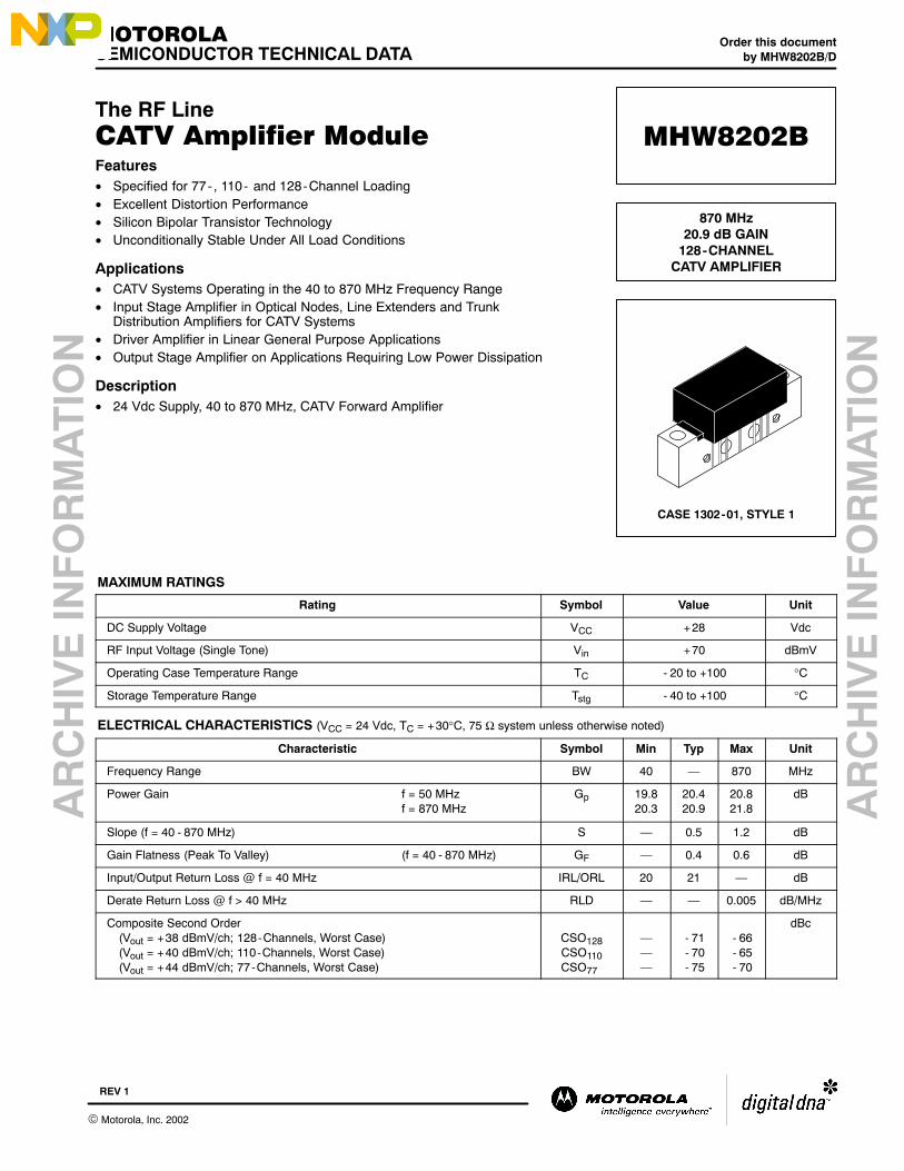
The RF LineCATV Amplifier ModuleFeatures• Specified for 77- , 110- and 128-Channel Loading• Excellent Distortion Performance• Silicon Bipolar Transistor Technology• Unconditionally Stable Under All Load Conditions
Applications• CATV Systems Operating in the 40 to 870 MHz Frequency Range• Input Stage Amplifier in Optical Nodes, Line Extenders and Trunk
Distribution Amplifiers for CATV Systems• Driver Amplifier in Linear General Purpose Applications• Output Stage Amplifier on Applications Requiring Low Power Dissipation
Description• 24 Vdc Supply, 40 to 870 MHz, CATV Forward Amplifier
MAXIMUM RATINGS
Rating Symbol Value Unit
DC Supply Voltage VCC +28 Vdc
RF Input Voltage (Single Tone) Vin +70 dBmV
Operating Case Temperature Range TC - 20 to +100 °C
Storage Temperature Range Tstg - 40 to +100 °C
ELECTRICAL CHARACTERISTICS (VCC = 24 Vdc, TC = +30°C, 75 Ω system unless otherwise noted)
Characteristic Symbol Min Typ Max Unit
Frequency Range BW 40 870 MHz
Power Gain f = 50 MHzf = 870 MHz
Gp 19.820.3
20.420.9
20.821.8
dB
Slope (f = 40 - 870 MHz) S 0.5 1.2 dB
Gain Flatness (Peak To Valley) (f = 40 - 870 MHz) GF 0.4 0.6 dB
Input/Output Return Loss @ f = 40 MHz IRL/ORL 20 21 dB
Derate Return Loss @ f > 40 MHz RLD 0.005 dB/MHz
Composite Second Order(Vout = +38 dBmV/ch; 128-Channels, Worst Case)(Vout = +40 dBmV/ch; 110-Channels, Worst Case)(Vout = +44 dBmV/ch; 77-Channels, Worst Case)
CSO128CSO110CSO77
- 71- 70- 75
- 66- 65- 70
dBc
Order this documentby MHW8202B/D
MOTOROLASEMICONDUCTOR TECHNICAL DATA
MHW8202B
870 MHz20.9 dB GAIN
128-CHANNELCATV AMPLIFIER
CASE 1302-01, STYLE 1
Motorola, Inc. 2002
REV 1

AR
CH
IVE
INF
OR
MA
TIO
N
AR
CH
IVE
INF
OR
MA
TIO
N
MHW8202B 2
MOTOROLA RF DEVICE DATA
ELECTRICAL CHARACTERISTICS continued (VCC = 24 Vdc, TC = +30°C, 75 Ω system unless otherwise noted)
Characteristic Symbol Min Typ Max Unit
Cross Modulation Distortion(Vout = +38 dBmV/ch, 128-Channels, Worst Case)(Vout = +40 dBmV/ch, 110-Channels, Worst Case)(Vout = +44 dBmV/ch, 77-Channels, Worst Case)
XMD128XMD110XMD77
- 67- 65- 58
- 62- 61- 57
dBc
Composite Triple Beat(Vout = +38 dBmV/ch, 128-Channels, Worst Case)(Vout = +40 dBmV/ch, 110-Channels, Worst Case)(Vout = +44 dBmV/ch, 77-Channels, Worst Case)
CTB128CTB110CTB77
- 67- 66- 65
- 63- 63- 63
dBc
Noise Figure f = 50 MHzf = 750 MHzf = 870 MHz
NF
3.85.05.6
5.06.57.0
dB
DC Current IDC 180 220 240 mA

AR
CH
IVE
INF
OR
MA
TIO
N
AR
CH
IVE
INF
OR
MA
TIO
N
3MHW8202BMOTOROLA RF DEVICE DATA
NOTES
AR
CH
IVE
INF
OR
MA
TIO
N
AR
CH
IVE
INF
OR
MA
TIO
N
MHW8202B 4
MOTOROLA RF DEVICE DATA
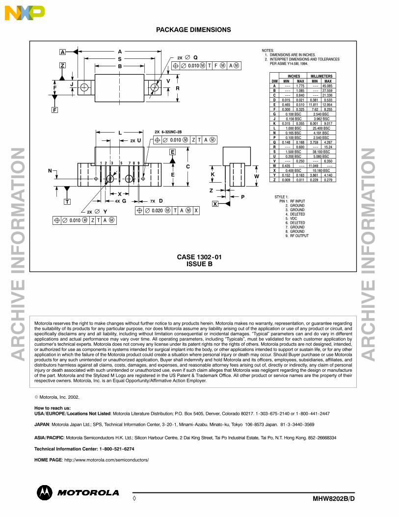
PACKAGE DIMENSIONS
CASE 1302-01ISSUE B
2
STYLE 1:PIN 1. RF INPUT
2. GROUND3. GROUND4. DELETED5. VDC6. DELETED
7. GROUND8. GROUND9. RF OUTPUT
1 5 8 9
J
BS
RV
Q2X
MFM0.010 A MT
MAM0.020 T
N
G
U
C
LMAM0.010 Z T
MAM0.010 Z T
6−32UNC−2B2X
W
P
K
3 7
X
A
F
F
A
Z
Y2X
2X
D7X4X
E
E
T X
Z
NOTES:1. DIMENSIONS ARE IN INCHES.2. INTERPRET DIMENSIONS AND TOLERANCES
PER ASME Y14.5M, 1994.
X
DIM
A
MIN MAX MIN MAX
MILLIMETERS
−−− 1.775 −−− 45.085
INCHES
B −−− 1.085 −−− 27.559
C −−− 0.840 −−− 21.336
D 0.015 0.021 0.381 0.533
E 0.465 0.510 11.811 12.954
F 0.300 0.325 7.62 8.255
G
J
K 0.315 0.355 8.001 9.017
L
N
P
Q 0.148 0.168 3.759 4.267
R −−− 0.600 −−− 15.24
S
U
V −−− 0.250 −−− 6.350
W 0.435 −−− 11.049 −−−
X
Y 0.152 0.163 3.861 4.140
Z 0.009 0.011 0.229 0.279
0.100 BSC
0.156 BSC
0.400 BSC
1.000 BSC
0.165 BSC
0.100 BSC
1.500 BSC
0.200 BSC
2.540 BSC
3.962 BSC
10.160 BSC
25.400 BSC
4.191 BSC
2.540 BSC
38.100 BSC
5.080 BSC
Motorola reserves the right to make changes without further notice to any products herein. Motorola makes no warranty, representation, or guarantee regardingthe suitability of its products for any particular purpose, nor does Motorola assume any liability arising out of the application or use of any product or circuit, andspecifically disclaims any and all liability, including without limitation consequential or incidental damages. Typical parameters can and do vary in differentapplications and actual performance may vary over time. All operating parameters, including Typicals, must be validated for each customer application bycustomers technical experts. Motorola does not convey any license under its patent rights nor the rights of others. Motorola products are not designed, intended,or authorized for use as components in systems intended for surgical implant into the body, or other applications intended to support or sustain life, or for any otherapplication in which the failure of the Motorola product could create a situation where personal injury or death may occur. Should Buyer purchase or use Motorolaproducts for any such unintended or unauthorized application, Buyer shall indemnify and hold Motorola and its officers, employees, subsidiaries, affiliates, anddistributors harmless against all claims, costs, damages, and expenses, and reasonable attorney fees arising out of, directly or indirectly, any claim of personalinjury or death associated with such unintended or unauthorized use, even if such claim alleges that Motorola was negligent regarding the design or manufactureof the part. Motorola and the Stylized M Logo are registered in the US Patent & Trademark Office. All other product or service names are the property of theirrespective owners. Motorola, Inc. is an Equal Opportunity/Affirmative Action Employer.
Motorola, Inc. 2002.
How to reach us:USA/EUROPE/Locations Not Listed: Motorola Literature Distribution; P.O. Box 5405, Denver, Colorado 80217. 1-303-675-2140 or 1-800-441-2447
JAPAN: Motorola Japan Ltd.; SPS, Technical Information Center, 3-20-1, Minami-Azabu. Minato-ku, Tokyo 106-8573 Japan. 81-3-3440-3569
ASIA/PACIFIC: Motorola Semiconductors H.K. Ltd.; Silicon Harbour Centre, 2 Dai King Street, Tai Po Industrial Estate, Tai Po, N.T. Hong Kong. 852-26668334
Technical Information Center: 1-800-521-6274
HOME PAGE: http://www.motorola.com/semiconductors/
MHW8202B/D◊