motors, electrical objective* uuesraiuii · /^^characteristics (tc's), and as indicated by the...
TRANSCRIPT
mmm 1
23 March 1970
U. S. ARMY TEST AND EVALUATION COMMAND COMMODITY ENGINEERING TEST PROCEDURE
Materiel Test Procedure 9-2-155 General Equipment Test Activity
D D C [?f?arpn^ QE
MOTORS, ELECTRICAL
1, OBJECTIVE*
{ APR 14 1971
UUesraiuii This document provides test methods and testing techniques'necessaryQ
y^to determine the technical performance' and safety characteristics of electrical jtnotors and associated tools and equipment as described in Qualitative Materiel
' 'Requirements (QMR's), Small Development Requirements (SDR's), and Technical /^^Characteristics (TC's), and as indicated by the particular design and to de-
termine the item's suitability for service tests.
*33
BACKGROUND
The electrical motor is one of the most useful and flexible devices vailable for the purpose of providing a source of mechanical energy.
Electric motors range extensively in physical size, electrical input requirements and output power, work producing energy available at the motor shaft. It is due to this wide range of characteristics that the Army has such an extensive need for devices of this type.
In terms of basic principles, the electrical motor is an energy con- verting device. The input side of the motor is connected to a source of elec- trical power. This electrical energy creates magnetic fields within the motor housing which interact with the metallic structure of the rotary mechanism pro- ducing mechanical forces on the rotor assembly and causing its motion. The rotation of the rotor assembly and, in turn, the motor shaft rotation provide for the mechanical energy at the output side, the energy being determined by the torque and rotational speed of thp shaft. The transfer characteristics of the motor combine to determine the motor efficiency, the percentage of the in- put electrical power converted to output mechanical power. Factors such as electrical eddy current losses and mechanical slippage prevent motors from being 100% efficient.
criteria: For the purpose of testing, motors can be classified by (3) sets of
1) Input characteristics - alternating current (AC), direct current (DC), universal (AC or DC).
2) Internal structure - each motor type by input characteristics can be further subdivided according to design characteristics (see Appendix A).
3) Output characteristics - all motors will possess some common
*This MTP is intended to be used as a basic guide in preparing actual test plans for the subject equipment. Specific criteria and test procedures must be determined only after careful appraisal of pertinent QMR's, SDR's, MC's, TC's and any other applicable documents.
-1- Roproducod by
NATIONAL TECHNICAL INFORMATION SERVICE
Spnncilield, Vs 22151
'DISTRIBUTION STATEMENT i
Approved for public release; Distribulion Unlimited L
^M
MTP 9-2-155 23 March 1970
output characteristics by test while others require tests peculiar to the type e.g., rotational speed measurement is required of all motors but constant rotational speed is synonomous with the syn- chronous motor.
The engineering test will provide for the evaluation of the motor in accordance with requirements associated with the above listed criteria in addi- tion to the general evaluations required of all Army materiel.
3. REQUIRED EQUIPMENT
a. Motor Test Stand(s) b. Electromagnetic Interferencf: Facilities, as required c. Environmental Test Facilities, including as applicable;
1 2 3 4 5 6 7 8 9
10 11 12
Temperature chamber, with cycling capabilities Temperature altitude chamber Temperature - Shock facility Altitude chamber Immersion test facility Dust test chamber Rain test chamber Moisture resistance test facility Humidity test chamber Fungus test chamber Salt-Fog test facility Explosive atmosphere test chamber
d. Shock Testing Facilities e. Vibration Testing Facilities f. Sound Level Measurement Equipment and Facilities including:
1) Microphones 2) öound level meter per ANSI-STD-S1.4-1961 3) Octave band analyzer per ANSI-STD-S1.2-1962 4) Sound anechoic chamber
g. Dielectric Strength Tester, 0-J000 VRMS, 25-60 Hz h. "Megger", 500 VDC i. Wheatstone Bridge, as required j. Voltmeters (AC and DC), as required k. Ammeters (AC and DC), as required 1. Ohmmeters (AC and DC), as required m. Wattmeters (AC and DC), as required n. Torque Generating Devices, as required including:
1) Dynamometer (reaction type) 2) Prony brake 3) Bucking motor
o. Thermometers, Liquid-in-Glass, 0F and 0C
-2-
.^_«™^_-*™—««»._

■■' " '■■" '■ "'■" ■ mmmmm^^^mmmm^m^^mmmmmmimmmemmimmr^^
yf
'
'■<
■
BLANK PAGE
r
N» .» .___
■ ■"■ -3-
-J
• :-mr~-':~~' '-■' m- **
i
1
^^OT Tl
MTP 9-2-155 23 March 1970
p. Tachometer and Compatible Electronic Counter q. Vibration Amplitude Measuring Set r. PhotOcraphic Equipment including:
1) Film (color and black and white) 2) Still camera 3) Flashbulbs or electronic Flash unit
Materials Handling Equipment, as required Miscellaneous Tools, as required Shipping Containers and Packaging Materials, ai required Thermocouples and Associated Recording Equipment, as required Feeler Gage Variable-Output Power-Supply (AC/DC) Torque Measuring Device, as required
s. t. u. v. w. X.
y.
REFERENCES
A. USATECOM Regulation 385-6, Verification of Safety of Materiel During Testing.
B. USATECOM Regulation 700-1, Value Engineering. C. USATECOM Regulation 705-4, Equipment Performance Report. D. USAGEIA (HEDGE) Human Factors Evaluation Data for General Equip-
ment. E. MIL-STD-108E, Definitions of. and Basic Requirements for. Enclo-
sures for Electric and Electronic Equipment. F. MIL-STD-129, Marking for Shipment and Storage. G. MIL-STD-130, Identification Marking of U. S. Military Property. H. MIL-STD-202D, Test Methods for Electronic and Electrical Com-
ponent Parts. I. MIL-STD-461, Electromagnetic Interference Requirements for
Equipment. J. MIL-STD-462, Electromagnetic Interference Characteristics,
Measurements of. K. MIL-STD-463, Definitions and Systems of Units - Electromagnetic
Interference Technology. L. MIL-STD-810B, Method 516, She k Tests. M. MIL-M-13786, Motors. Fractional Horsepower. Direct Current and
Universal. N. MIL-0-5606, Oil. Hydraulic. 0. MIL-P-16298, Preservation. Packaging. Packing and Marking of
Electric Machines Having Rotating Parts, and Associated Repair Parts. * " ~ "
P. AMCP 706-134, Maintenance Guide for Design. Q. ANSI-STD-S1.2-1962, Physical Measurement of Sound. R. MSI-STD-S1.4-1961, General Purpose Sound Level Meters. S. Handbook of Noise Meaüurement, General Radio Company. T. HEL-STD-S1-63B, Maximum Noise Level for Army Materiel Command
Equipment. U. NEMA-MG-1-1967, Motors and Generators. National Electric Manu-
facturer's Association. V. NEMA-MG-2-1968, Motors and Generators. (Safety Standard for
-3-
Uttmt^mmmtmmm
r
MTP 9-2-155 23 March 1970
Construction and Guide for Selection. Installation and Use of Integral Horsepower Motors and Generators).
W. Institute of Electrical and Electronics Engineers, Inc. New York, N. Y. , including the following IEEE Publications:
1) No. 1, General Principles Upon Which Temperature Limits are Based in the Rating of Electrical Equipment; (under revision).
2) No. 4, Measurement of Voltage in Dielectric Tests; (under revision) .
3) No. 43, Testing Insulation Resistance of Rotating Electric Machinery. Recommended Practice for; Mar. 1961.
4) No. 51, Dielectric Tests. Guiding Principles for; June 1955. 5) No. 112A, Polyphase Induction Motors and Generators. Test
Procedure for; Sept. 1964. 6) No. 113, Direct-Current Machines. Test Code for; Dec. 1962. 7) No. 114, Single-Phase Induction Motors, Test Procedure for;
Mar. 1958. 8) No. 115, Synchronous Machines. Test Procedure for; Mar. 1965 9) No. 116, Carbon Brushes. Test Code for; Dec. 1958.
10) No. 118, Resistance Measurement. Master Test Code for; May 1949.
11) No. 119, Temperature Measurement of Electric Apparatus. Mast- er Test Procedure for; Dec. 1966.
12) Nc. 120, Electrical Measurements in Power Circuits. Master Test Code for; Nov. 1955.
13) No. 121, Rotary Speed, Guide for Measurement of; April 1959.
X. NFPA Handbook of the National Electrical Code. McGraw-Hill, New York, 1966.
Y. MTP 9-2-503, Durability. Z. MTP 10-2-500, Physical Characteristics.
AA. MTP 10-2-501, Operator Training and Faimiliarization. AB. MTP 10-2-503, Surface Transportability. AC. MTP 10-2-505, Human Factors Evaluation. AD. MTP 10-2-507, Maintenance Evaluation. AE. MTP 10-2-508. Safety. AF. MTP 10-2-511, Quality Assurance. AG. MTP 10-2-512, Reliability.
5. SCOPS
5.1 SUMMARY
This procedure describes the preparation for and the method of eval- uating the characteristics of electric motors as follows:
a. Preparation for Test - A determination of the test item condi- tion upon its arrival, and its physical characteristics. Operator training and familiarization, other preparatory procedures including pre-operational checks are outlined.
b. Electrical Measurements - An evaluation of the test item's elec- trical characteristics to determine its condition prior to normal operation i
-4-
— — II*I aaaHaaaMaauDH^^MH,
MTP 9-2-155 23 March 1970
and to obtain data for later comparison tests. c. Dynamic Balance - A determination of the amplitude of vibration
on the test item bearing housing and a balancing of the test item shaft to bring the vibration characteristics within prescribed limits.
d. Operational Performance - An evaluation to examine specific oper- ational design characteristics in order to determine the test item's ability to perform its required function. Test item controls shall also be evaluated.
e. Inclined Operation - An evaluation to determine the operating integrity of the test items equipped with sleeve bearings.
f. Mechanical Shock and Vibration Tests - An evaluation to deter- mine the test item's ability to withstand expected »hock and vibration con- ditions.
g. Electromagnetic Interference - An evaluation to determine the degree to which the test item procedures radiated or line-conducted inter- ference .
h. Durability - An evaluation of the test item's ability to retain original physical, electrical, and performance characteristics after extended operation.
i. Environmental Tests - A series of evaluations designed to ex- amine and measure changes in the performance and physical characteristics of the test item when it is subjected to controlled changes in environmental para- meters.
j. Transportability - An evaluation to determine the ability of the test item and its container to withstand the forces which it will experience during normal handling and transporting.
k. Maintenance - An evaluation to determine and appraise the test item's maintenance characteristics and requirements, a verification and ap- praisal of its malfunctions, an evaluation of the test item's associated publications and other common and special support elements (maintenance test package) an appraisal of the test item's design for maintainability (AMCP 706- 134: accessibility, ease of maintenance, standardization, and interchange- ability) , an evaluation of indicators which express the effects of appropriate preceding aspects.
1. Safety - An evaluation to determine the safety characteristics and possible hazards of the test item.
m. Human Factors - An evaluation to determine the adequacy of the design and performance characteristics of the test item and associated equip- ment in terms of conformance to accepted human factors engineering design criteria. The sound noise level of the test item will also be determined.
n. Value Analysis - An evaluation directed at analyzing the primary functions and features of the test item for the purpose of reducing the cost of the test item without compromising the desired performance and safety characteristics.
o. Quality Assurance - A study to determine the quality of the test item.
5.2 LIMITATIONS
The test procedure contained in this MTP are applicable to electrical motors in general, either AC, DC, or universal.
-5-
MTP 9-2-155 23 March 1970
6. PROCEDURES
6.1 PREPARATION FOR TEST
6.1.1 Initial Inspection
6.1.1.1 Shipping and Packaging Inspections
a. Examine the shipping method, preservation and packaging and de- termine and record any non-conformance with MIL-P-16298.
b. Determine and record whether the shipping package is marked in accordance with MIL-STD-129.
c. Record the following:
1) Evidence of damage or deterioration to packaging or shipping components and materials.
2) All identification markings. 3) All printed material ac /mpanying the test item and agree-
ment with the package markings. 4) Whether maintenance test package was provided.
d. Remove the test item from its shipping carrier, or container, and record the following for the unpacking operation:
1) Personnel required. 2) Equipment required. 3) Time required. 4) Comments regarding the method and materials used to secure
the test item.
6.1.1.2 Test Item Inspection
Inspect the test item and determine and record the following, as applicable:
a. Any instances of non-compliance with the marking requirements of MIL-STD-130.
b. Any evidence of defects, damage, and wear in the manufacturing materials and workmanship including the following, in particular:
1) Treatment of metal surfaces for rust prevention and paint- ing not in accordanoB with the best commercial practices.
NOTE: Painted surfaces shall be smooth and uniform without runs and sags.
2) For component junctions:
a) Rivets not of a size so as to completely fill the shank holes or have insufficient metal on the flared end to provide adequate fastening strength.
-6-
••■MMHM i
r
—"^ww«
MTP 9-2-155 23 March 1970
b) Soldering not smooth, sound and clean. c) Welding not free from slag, cracks, fractures not having
a smooth, clean appearance. d) Hardware not of sufficient size and strength or not
tightly drawn. e) Seams and joints not having good fit and alignment and
having sharp edges or burrs.
3) Any doors and covers not operating easily and any defect in mating or alignment.
4) All controls, indicators, access ports and points of attach- ment not marked clearly and legibly as to their function.
5) Wiring not insulated and protected in accordance with the applicable sections of the National Electrical Code.
6) Electrical cabling and connector damage and improper mating of connecting parts.
c. Record the test item nameplate data and note any non-conformance with the following minimum nameplate marking requirements, as applicable:
1) For D-C motors: as specified by NEMA MG-1-1967, paragraph 1-10.62.
2) For A-C motors: as specified by NEMA MG-1-1967, paragraphs 1-10.38, 1-10.39 or 1-20.60.
3) For synchronous motors: as specified by NEMA MG-1-1967, paragraph 1-21.63.
4) For definite-purpose motors: as specified by the applicable paragraph of NEMA MG-1-1967, part 18.
6.1.2 Inventory Check
Verify completeness of the test item and associated maintenance test package and material with the Basic Issue Item List (BIIL) and file an Equip- ment Performance Report (EPR) if items are missing or inadequate.
6.1.3 Physical Characteristics
The physical characteristics of the test item shall be determined by performing the applicable sections of MTP 10-2-500 and the following recorded as applicable:
a. Motor electrical type - AC, DC, or Universal b. Internal construction or winding type c. Horsepower rating d. Duty cycle e. Maximum ambient service temperature f. Rated voltage g. Rated frequency h. Full load torque i. Locked rotor torque and current j. Full load current
•7-
'•^^^^^^»■■— ' '-''■ -■—■^"^^^^^^^^^■■■■B
MTP 9-2-155 23 March 1970
k. Full load speed 1. Efficiency m. Enclosure type n. Direction of rotation o. Electrical connector types p. Lubrication required q. Weight r. Overload protection s. Operating position t. Class of insulation
6.1.4 Operator Training and Familiarization
Orient test personnel using the criteria of MTP 10-2-501 and record all pertintent data.
6.1.5 Pre-Operational Checks
Perform the following, as applicable:
a. Remove all preservatives from the test item and perform and re- cord all required assembly operations.
b. Check the lubricant levels of the test item and record the follow- ing:
1) Accessibility of lubrication points such as oil holes, grease fittings and grease cups.
2) Lubrication points so designed as to exclude foreign material. 3) Amounts and types of lubricant added, in accordance with
maintenance instructions.
c. Check the rotational concentricity of the test item rotor shaft by rotating the rotor and record any evidence of rubbing or binding.
d. Check the mechanical strength of test item terminals and leads and record any evidence of damage or inadequacy when the following tests are performed:
1) ^pply pull to each lead/terminal at a force of five pounds.
NOT^.S: 1. Pull the entire assembly in cases where connectors are used.
2. Apply ^uil in the direction which tends to rotate the terminal or lead.
2) If a terminal shows evidence of beading during the pull test, bend it back and forth five times to a 45° angle each side of center.
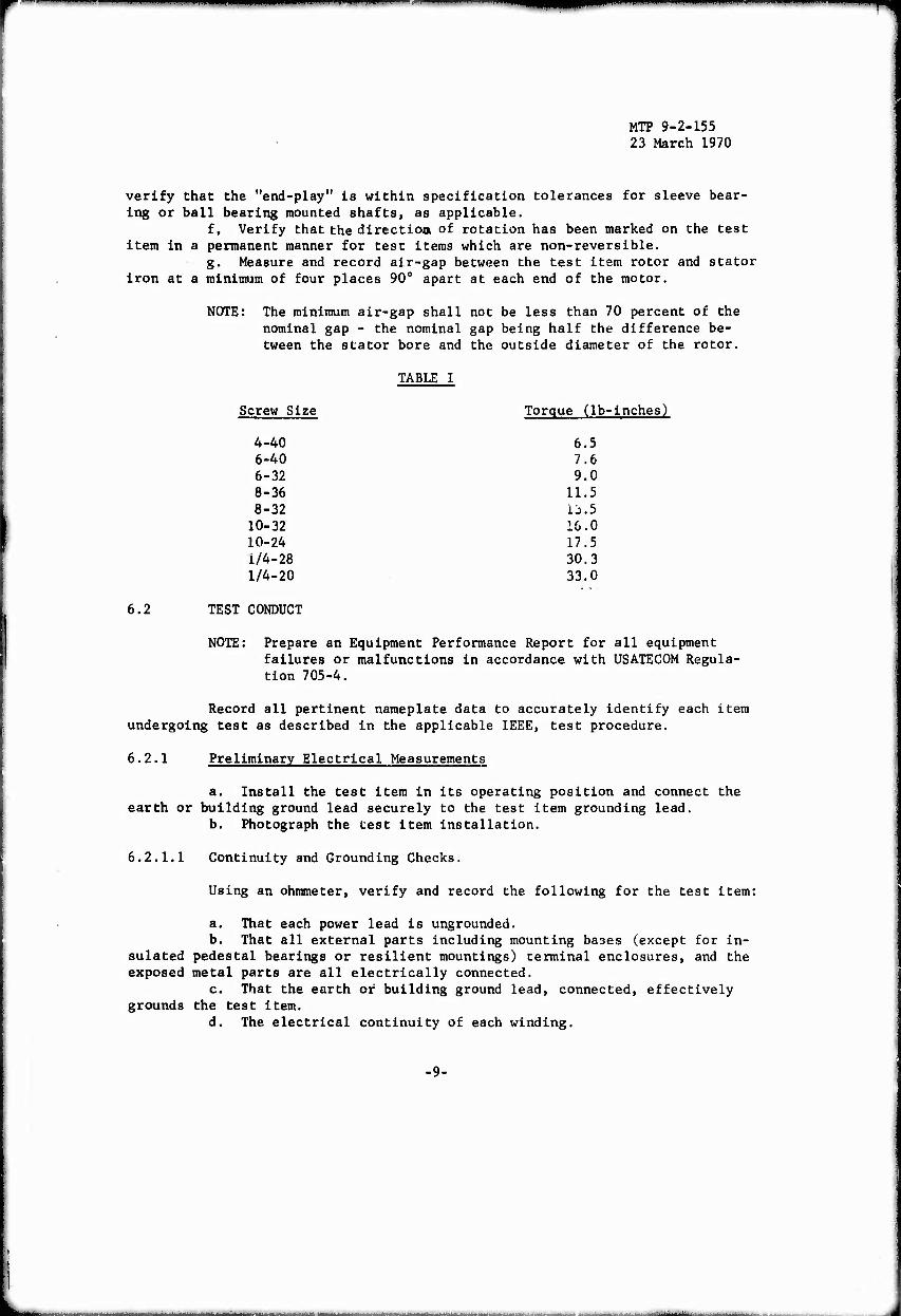
3) Apply torque to stud-type terminals as given in Table I.
e. Measure and record the test item rotor shaft bearing "end-play" at standstill by alternately depressing and releasing the rotor shaft, and
>
1 ll «l "n ■■■»"
MTP 9-2-155 23 March 1970
verify that the "end-play" is within specification tolerances for sleeve bear- ing or ball bearing mounted shafts, as applicable.
f, Verify that the direction, of rotation has been marked on the test item in a permanent manner for test items which are non-reversible.
g. Measure and record air-gap between the test item rotor and stator iron at a minimum of four places 90° apart at each end of the motor.
NOTE: The minimum air-gap shall not be less than 70 percent of the nominal gap - the nominal gap being half the difference be- tween the stator bore and the outside diameter of the rotor.
6.2
TABLE I
Screw Size Torque (lb-inches)
4-40 6.5 6-40 7.6 6-32 9.0 8-36 11.5 8-32 lj.5
10-32 16.0 10-24 17.5 1/4-28 30.3 1/4-20 33.0
TEST CONDUCT
NOTE: Prepare an Equipment Performance Report for all equipment failures or malfunctions in accordance with USATECOM Regula- tion 705-4,
Record all pertinent nameplate data to accurately identify each item undergoing test as described in the applicable IEEE, test procedure.
6.2.1 Preliminary Electrical Measurements
a. Install the test item in its operating position and connect the earth or building ground lead securely to the test item grounding lead.
b. Photograph the test item installation.
6.2.1.1 Continuity and Grounding Checks.
Using an ohmmeter, verify and record the following for the test item:
a. That each power lead is ungrounded. b. That all external parts including mounting bases (except for in-
sulated pedestal bearings or resilient mountings) terminal enclosures, and the exposed metal parts are all electrically connected.
c. That the earth or building ground lead, connected, effectively grounds the test item.
d. The electrical continuity of each winding.
■9-
■■--■■ ■■ -
MTP 9-2-155 23 March 1970
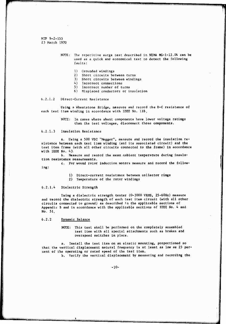
NOTE: The repetitive surge test described in NEMA MG-1-12.04 can be used as a quick and economical test to detect the following faults:
1) Grounded windings 2) Short circuits between turns 3) Short circuits between windings 4) Incorrect connections 5) Incorrect number of turns 6) Misplaced conductors or insulation
6.2.1.2 Direct-Current Resistance
Using a Wheatstone Bridge, measure and record the D-C resistance of each test item winding in accordance with IEEE No. 118.
NOTE: In cases where shunt components have lower voltage ratings than the test voltages, disconnect those components.
6.2.1.3 Insulation Resistance
a. Using a 500 VDC "Megger", measure and record the insulation re- sistance between each test item winding (and its associated circuit) and the test item frame (with all other circuits connected to the frame) in accordance with IEEE No. 43-
b. Measure and record the mean f-mbient temperature during insula- tion resistance measurements.
c. For wound rotor induction motors measure and record the follow- ing:
1) Direct-current resistance between collector rings 2) Temperature of the rotor windings
6.2.1.4 Dielectric Strength
Using a dielectric strength tester (0-3000 VRMS, 25-60Hz) measure and record the dielectric strength of each test item circuit (with all other circuits connected to ground) as described in the applicable sections of Appendix B and in accordance with the applicable sections of IEEE No. 4 and No. 51.
6.2.2 Dynamic Balance
NOTE: This test shall be performed on the completely assembled test item with all special attachments such as brakes and overspeed switches In place.
a. Install the test item on an elastic mounting, proportioned so that the vertical displacement natural frequency is at least as low as 25 per- cent of the operating or rated speed of the test item.
b. Verify the vertical displacement by measuring and recording the
10-
■MHIttlMMa^.

r
♦
MTP 9-2-155 23 March 1970
the amount that the elastic mounting is compressed by the test item weight in accordance with the following table:
TABLE II
MOTOR SPEED (RPM) COMPRESSION (inches)
600 2-1/4 720 1-9/16 900 1 1200 9/16 1800 1/A 3600 1/16 7200 1/64
NOTES: 1. The required deflection is inversely proportional to the speed squared „
(Deflecticn = ( —) \ rpm/
2. Mounting pad static compression shall not be greater than 1/2 of its original nominal thickness.
c. Measure and record the amplitude of vibration on the bearing hous- ing in the direction giving the maximum amplitude with the motor running, the axis of the shaft in normal operating position and at normal voltage.
NOTES: 1. AC motors shall be operated at rated voltage and fre- quency .
2. DC motors shall be operated at maximum rated speed. 3. Service and universal motors shall be run at normal oper-
ating speed.
load.
tion:
Balance the test item shaft with the test item operating at no
NOTES: 1. Balance must be achieved by using no more than 1/2 of a "standard" key in the keyseat, where a "standard" key shall be taken to mean a key of full length flush with the top of the keyseat. Preloading washers may be used to clamp axial vibrations.
2. When balanced as described the degree of balance shall be as specified in Table III.
e. Record the following at the completion of the balancing opera-
1) Amount of key required to achieve dynamic balance 2) Operating speed 3) Maximum peak-to-peak amplitude of vibration after balancing 4) Direction of maximum amplitude
•11-
i
MTP 9-2-155 23 March 1970
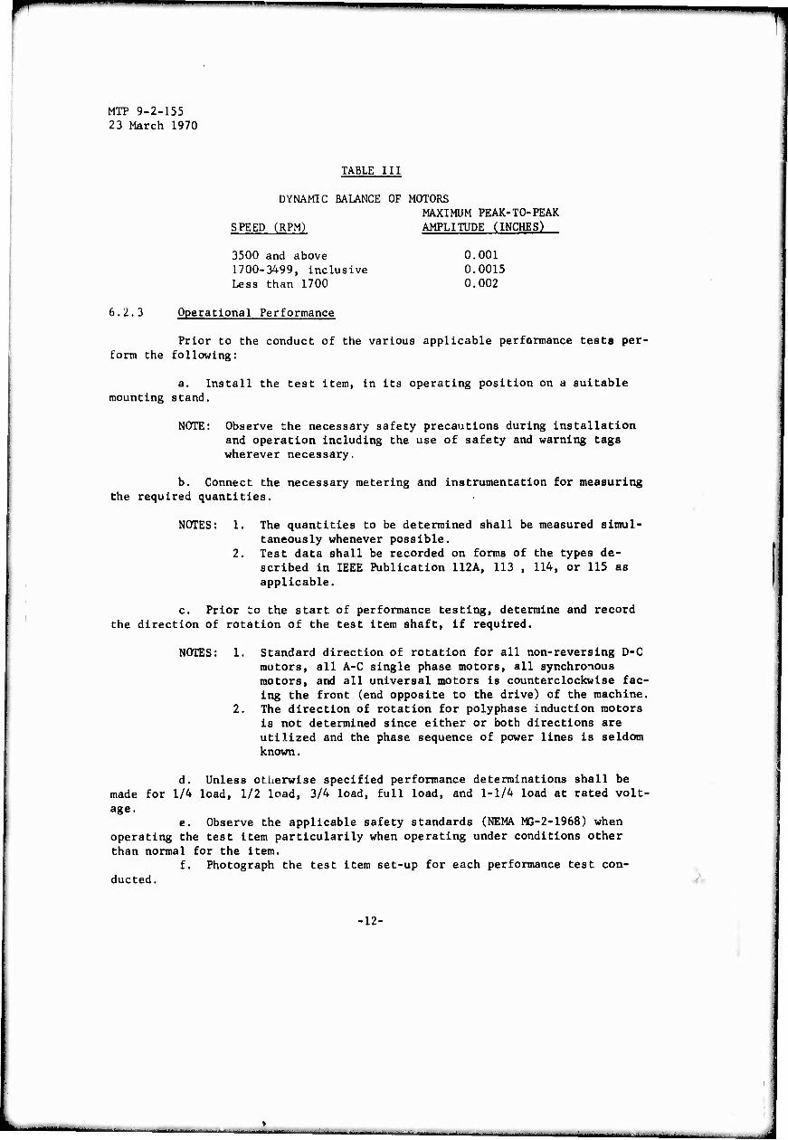
TABLE III
DYNAMIC BALANCE OF MOTORS MAXIMUM PEAK-TO-PEAK
SPEED (RPM) AMPLITUDE (INCHES)
3500 and above 0.001 1700-3499, inclusive 0.0015 Less than 1700 0.002
6.2.3 Operational Performance
Prior to the conduct of the various applicable performance tests per- form the following:
a. Install the test item, in its operating position on a suitable mounting stand.
NOTE: Observe the necessary safety precautions during installation and operation including the use of safety and warning tags wherever necessary.
b. Connect the necessary metering and instrumentation for measuring the required quantities.
NOTES: 1. The quantities to be determined shall be measured simul- taneously whenever possible.
2. Test data shall be recorded on forms of the types de- scribed in IEEE Publication 112A, 113 , 114, or 115 as applicable.
c. Prior to the start of performance testing, determine and record the direction of rotation of the test item shaft, if required.
NOTES: 1. Standard direction of rotation for all non-reversing D-C motors, all A-C single phase motors, all synchronous motors, and all universal motors is counterclockwise fac- ing the front (end opposite to the drive) of the machine.
2. The direction of rotation for polyphase induction motors is not determined since either or both directions are utilized and the phase sequence of power lines is seldom known.
d. Unless otherwise specified performance determinations shall be made for 1/4 load, 1/2 load, 3/4 load, full load, and 1-1/4 load at rated volt- age.
e. Observe the applicable safety standards (NEMA MG-2-1968) when operating the test item particularily when operating under conditions other than normal for the item.
f. Photograph the test item set-up for each performance test con- ducted.
•12-
'

MTP 9-2-155 23 March 1970
t 6.2.3.1 Direct Current Motors
NOTE: All tests shall be conducted with the test item shaft rotating in the proper direction.
Determine and record the performance characteristics of the test item a-, described in the applicable sections of IEEE No. 113 including the following:
a. Static tests for the determination of:
1) Potential drop of field coils 2) Polarity of field coils
NOTE; Other static tests are performed during preliminary checks in previous paragraphs.
b. Complete test series, with data collected for the determination of:
1) Magnetic saturation curve 2) Successful commutation 3) Regulation of speed, including:
a) No-load to rated-load b) Rated-load to overload
4) Efficiency at required loads. Record method used to deter- mine efficiency.
5) Load characteristics for, as applicable:
a) Fractional-horsepower motors b) Integral-horsepower motors
6) Temperature rise of the following, at rated load(s), as ap- plicable:
a) Armature windings b) Armature core c) Shunt field d) Series field e) Commutator pole field f) Commutator bars g) Collector rings
6.2.3.2 Alternating Current Motors
Perform the tests as applicable to the test item.
NOTE: Induction motor performance is highly dependent on the volt- age, frequency, wave shape, and the balance in magnitude and in phase angle of the power source. A suitable source of
-13-
i ■ ■■! II> -■ mm. m
MTP 9-2-155 23 March 1970
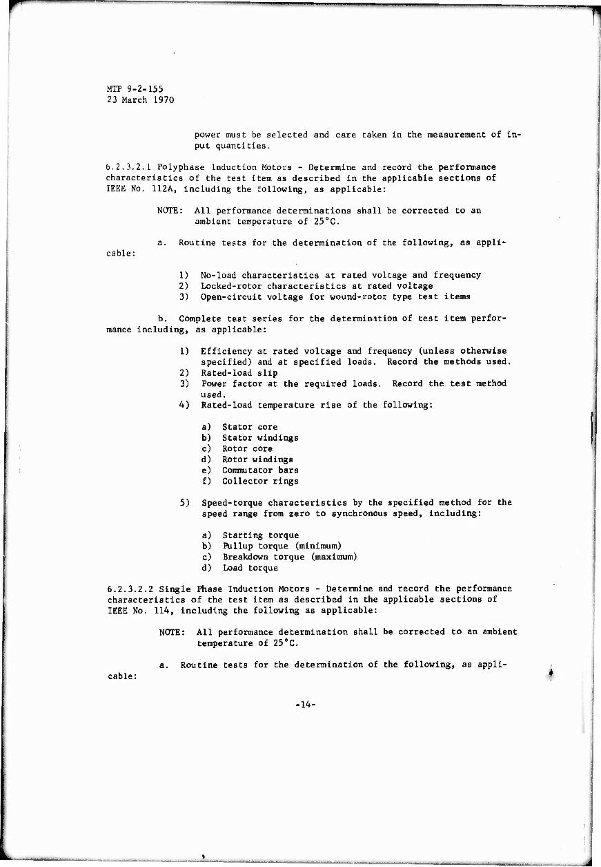
power must be selected and care taken in the measurement of in- put quantities.
6.2.3.2.1 Polyphase Induction Motors - Determine and record the performance characteristics of the test item as described in the applicable sections of IEEE No. 112A, including the following, as applicable:
NOTE: All performance determinations shall be corrected to an ambient temperature of 250C.
a. Routine tests for the determination of the following, as appli- cable:
1) No-load characteristics at rated voltage and frequency 2) Locked-rotor characteristics at rated voltage 3) Open-circuit voltage for wound-rotor type test items
b. Complete test series for the determination of test item perfor- mance including, as applicable:
1) Efficiency at rated voltage and frequency (unless otherwise specified) and at specified loads. Record the methods used.
2) Rated-load slip 3) Power factor at the required loads. Record the test method
used. 4) Rated-load temperature rise of the following:
a) Stator core b) Stator windings c) Rotor core d) Rotor windings e) Commutator bars f) Collector rings
5) Speed-torque characteristics by the specified method for the speed range from zero to synchronous speed, including:
a) Starting torque b) Pullup torque (minimum) c) Breakdown torque (maximum) d) Load torque
6.2.3.2.2 Single Phase Induction Motors - Determine and record the performance characteristics of the test item as described in the applicable sections of IEEE No. 114, including the following as applicable:
NOTE: All performance determination shall be corrected to an ambient temperature of 250C.
cable: Routine tests for the determination of the following, as appli-
■14-
» Ml.i.r.^*....mifnl..T.^l.l1il, irn-i .m. ..... .i..^».^;,., .^.-^ ■ . ._ ^ „n „ftlirt,-- -
r
MTP 9-2-155 23 March 1970
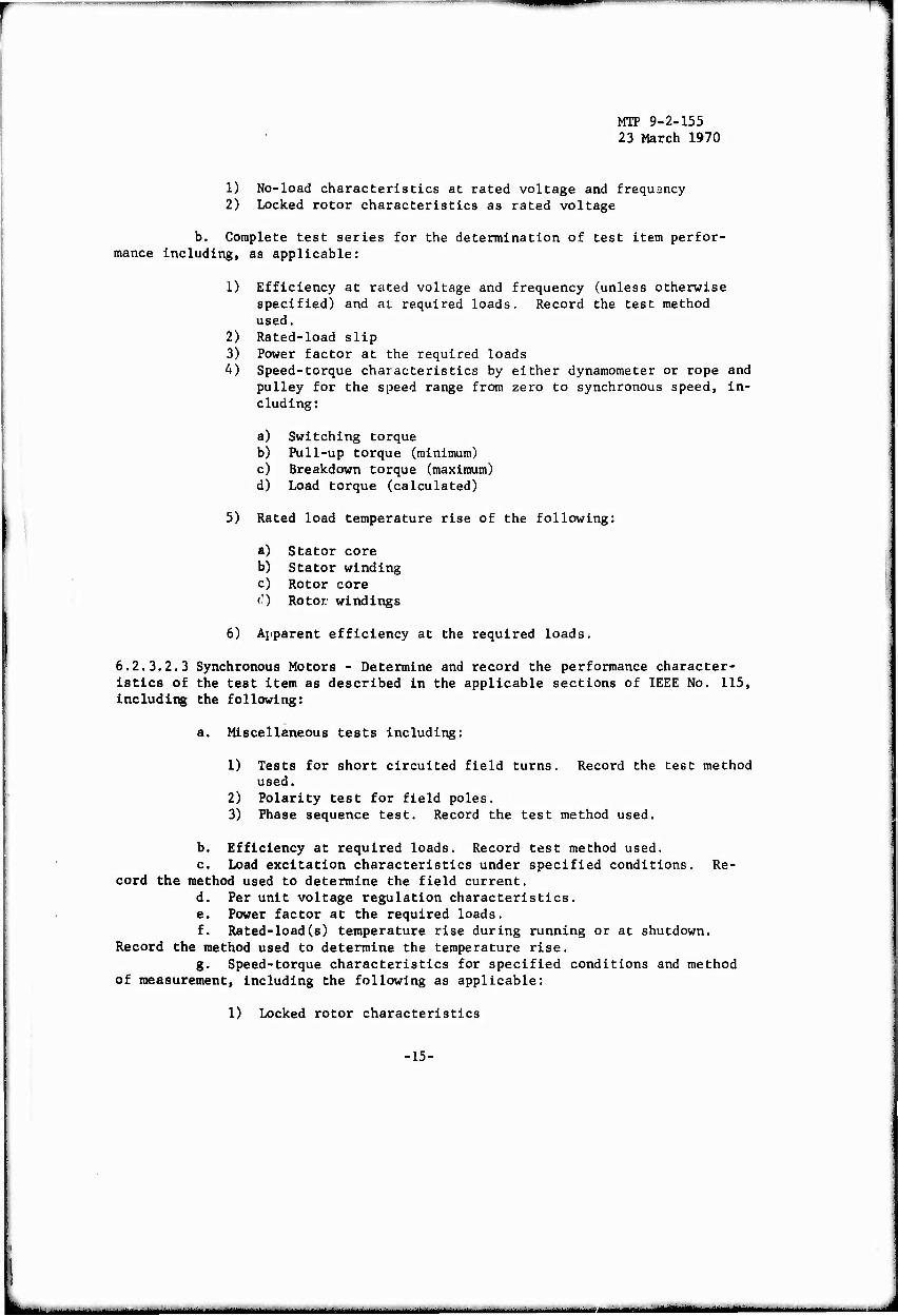
1) No-load characteristics at rated voltage and frequency 2) Locked rotor characteristics as rated voltage
b. Complete test series for the determination of test item perfor- mance including, as applicable:
1) Efficiency at rated voltage and frequency (unless otherwise specified) and at required loads. Record the test method used.
2) Rated-load slip 3) Power factor at the required loads 4) Speed-torque characteristics by either dynamometer or rope and
pulley for the speed range from zero to synchronous speed, in- cluding:
a) Switching torque b) Pull-up torque (minimum) c) Breakdown torque (maximum) d) Load torque (calculated)
5) Rated load temperature rise of the following:
a) Stator core b) Stator winding c) Rotor core C) Rotor, windings
6) Apparent efficiency at the required loads.
6.2.3.2.3 Synchronous Motors - Determine and record the performance character- istics of the test item as described in the applicable sections of IEEE No. 115, including the following:
a. Miscellaneous tests including:
1) Tests for short circuited field turns. Record the test method used.
2) Polarity test for field poles. 3) Phase sequence test. Record the test method used.
b. Efficiency at required loads. Record test method used. c. Load excitation characteristics under specified conditions. Re-
cord the method used to determine the field current. d. Per unit voltage regulation characteristics. e. Power factor at the required loads. f. Rated-load(s) temperature rise during running or at shutdown.
Record the method used to determine the temperature rise. g. Speed-torque characteristics for specified conditions and method
of measurement, including the following as applicable:
1) Locked rotor characteristics
■15-
iMaaaia

MTP 9-2-155 23 March 1970
2) Pull-up torque 3) Nominal pull-in torque 4) Pull-out torque
h. Synchronous machine quantities and sudden short circuit tests as
specified and by selected methods.
6.2.4 Inclined Operation
Perform the following for only those test items equipped with sleeve
bearings:
a. Operate the test item with its shaft inclined at an angle of 15 degrees with the front end of the test item low for a minimum of 30 minutes at
a rated speed and rated-load. b. During operation perform the following:
1) Determine that the test item dynamic balance is satisfactory by using the procedures of paragraph 6.2.2.
2) Determine and record the following, as applicable:
a) Any evidence of pounding or grinding at the bearing. b) Evidence of lubrication oil-rings striking against or
rubbing the sides of the oil well. c) Evidence of oil-ring "dancing" or pronounced irregularity
of oil-ring movement. d) Any slinging of oil into the motor by the shaft.
3) Photograph the test set-up. 4) Record the following:
a) Line voltage b) Line current c) Power consumption at rated-load d) Full-load speed e) Ambient temperature
c. At the completion of the test determine and record the following:
1) Test item temperatures as required during temperature rise
tests. 2) Bearing/bearing housing temperature. 3) Lubricating oil temperature. 4) Duration of the test run.
d. Repeat steps a, b and c with the test item installed in the fol-
lowing positions:
1) Shaft inclined 15 degrees, rear end low. 2) Shaft horizontal, test item base tilted 15 degrees to the
right.
-16-
I -■ ■ ■ ■ - ■ - - - ■ - ■
MTP 9-2-155 23 March 1970
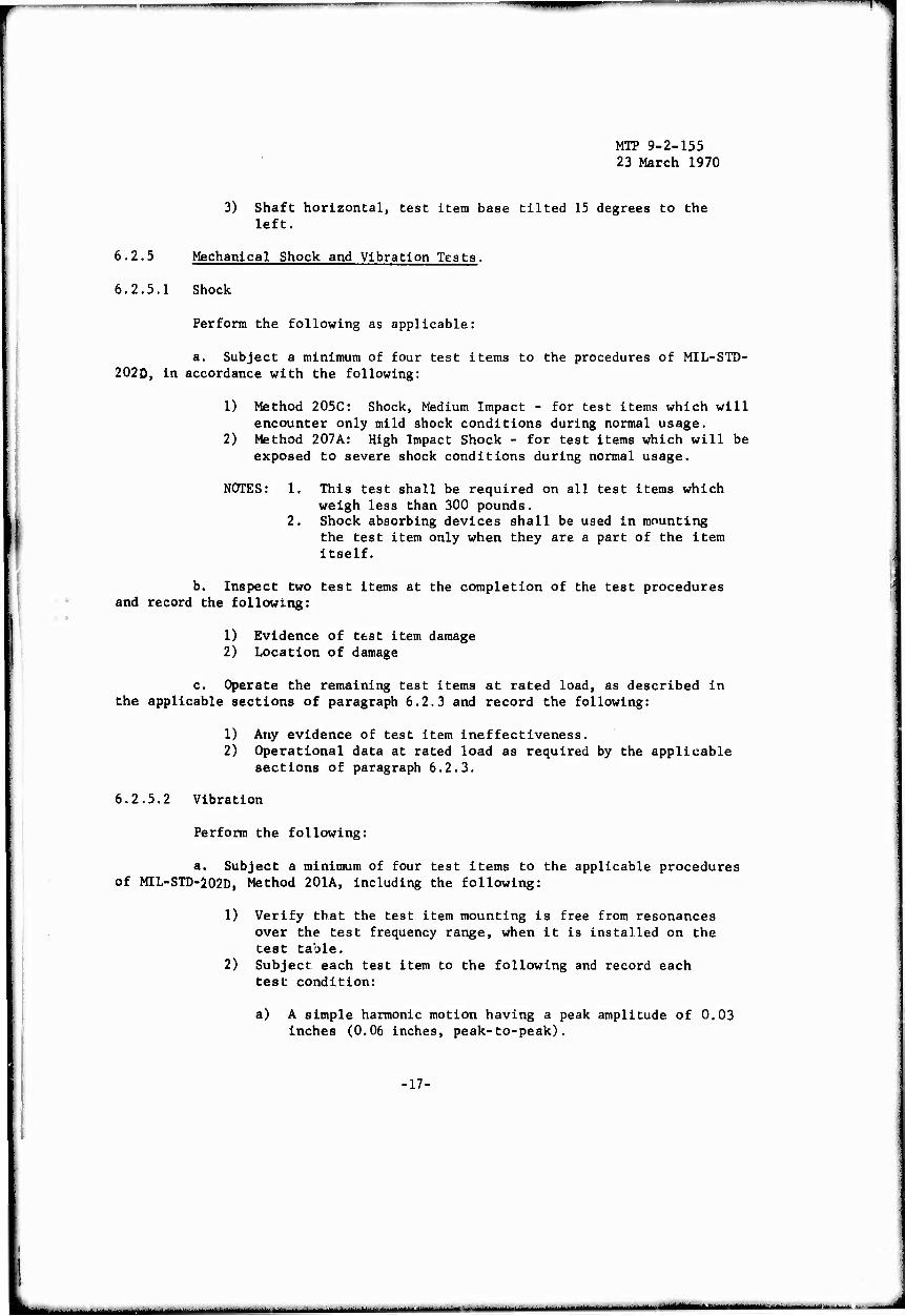
3) Shaft horizontal, test item base tilted 15 degrees to the left.
6.2.5 Mechanical Shock and Vibration Tests.
6.2.5.1 Shock
Perform the following as applicable:
a. Subject a minimum of four test items to the procedures of MIL-STD- 202D, in accordance with the following:
1) Method 205C: Shock, Medium Impact - for test items which will encounter only mild shock conditions during normal usage.
2) Method 207A: High Impact Shock - for test items which will be exposed to severe shock conditions during normal usage.
NOTES: I. This test shall be required on all test items which weigh less than 300 pounds.
2. Shock absorbing devices shall be used in mounting the test item only when they are a part of the item itself.
b. Inspect two test items at the completion of the test procedures and record the following:
1) Evidence of test item damage 2) Location of damage
c. Operate the remaining test items at rated load, as described in the applicable sections of paragraph 6.2.3 and record the following:
1) Any evidence of test item ineffectiveness. 2) Operational data at rated load as required by the applicable
sections of paragraph 6.2.3.
6.2.5.2 Vibration
Perform the following:
a. Subject a minimum of four test items to the applicable procedures of MIL-STD-202D, Method 201A, including the following:
1) Verify that the test item mounting is free from resonances over the test frequency range, when it is installed on the test table.
2) Subject each test item to the following and record each test condition:
a) A simple harmonic motion having a peak amplitude of 0.03 inches (0.06 inches, peak-to-peak).
■17-
Ml
111 ■"■ 1—
MTP 9-2-155 23 March 1970
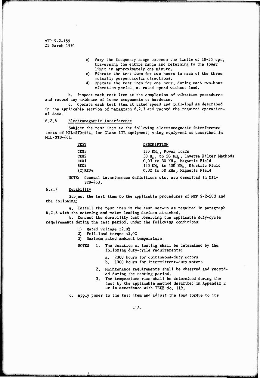
b) Vary the frequency range between the limits of 10-55 cps, traversing the entire range and returning to the lower limit in approximately one minute.
c) Vibrate the test item for two hours in each of the three mutually perpendicular directions.
d) Operate the test item for one hour, during each two-hour vibration period, at rated speed without load.
b. Inspect each test item at the completion of vibration procedures and record any evidence of loose components or hardware.
c. Operate each test item at rated speed and full-load as described in the applicable section of paragraph 6.2.3 and record the required operation- al data.
6.2.6 Electromagnetic Interference
Subject the test item to the following electromagnetic interference tests of MIL-STD-462, for Class IIB equipment, using equipment as described in M1L-STD-461:
TEST DESCRIPTION
CE03 150 KKj, Power loads CE05 30 Hj , to 50 MHg , Inverse Filter Methods RE01 0.03 to 30 KHj;, Magnetic Field RE02 150 KHz to 400 MHg, Electric Field (T)RE04 0.02 to 50 KHz, Magnetic Field
NOTE: General interference definitions etc. are described in MIL- STD-463.
6.2.7 Durability
Subject the test item to the applicable procedures of MTP 9-2-503 and the following:
a. Install the test item in the test set-up as required in paragraph 6.2.3 with the metering and motor loading devices attached.
b. Conduct the durability test observing the applicable duty-cycle requirements during the test period, under the following conditions:
1) Rated voltage ±2.0% 2) Full-load torque ±2.0% 3) Maximum rated ambient temperature
NOTES: 1. The duration of testing shall be determined by the following duty-cycle requirements:
a. 2000 hours for continuous-duty motors b. 1000 hours for intermittent-duty motors
2. Maintenance requirements shall be observed and record- ed during the testing period.
3. The temperature rise shall be determined during the test by the applicable method described in Appendix E or in accordance with IEEE No. 119.
c. Apply power to the test item and adjust the load torque to its
-18-
■ ■■■ - "— • '■ ■

MTP 9-2-155 23 March 1970
required value. d. Record the following at the start of the test:
1) Date 2) Starting time 3) Duty-cycle description 4) Applied voltage 5) Applied torque 6) Ambient air temperature 7) Required temperature rise data including as applicable:
a) Resistance of each test item winding or b) Temperature of each test item winding
e. Measure and record the following at the end of ecch 100-hour elapsed period during the test, in tabular form:
1) Input power 2). Full-load speed 3) Motor case temperature 4) Ambient air temperature 5) Winding temperatures or resistances, as applicable 6) Elapsed time from the start of the test
f. Record the following at the completion of the durability testing:
1) Duration of the test period 2) Portion of the duty cycle utilized for test item operation
g. Examine the test item at the completion of the test run and re- cord any signs of accelerated wear and potential equipment failures, including the following as applicable:
1) Damage to any component, material, or surface 2) Loosening of hardware 3) Excessive housing temperature 4) Lubricant leakage 5) Insulation deterioration
h. Record the following for any test item defect found during the examination:
1) Nature of defect 2) Location of the defect 3) Cause of the defect, if known 4) Recommended remedy
NOTE: In the event of equipment malfunction during the durability test, the procedures of the maintenance section will be performed and the durability test rerun following repair
of the test item.
-19-
■a—-—-"-——-
^mmm
MTP 9-2-155 23 March 1970
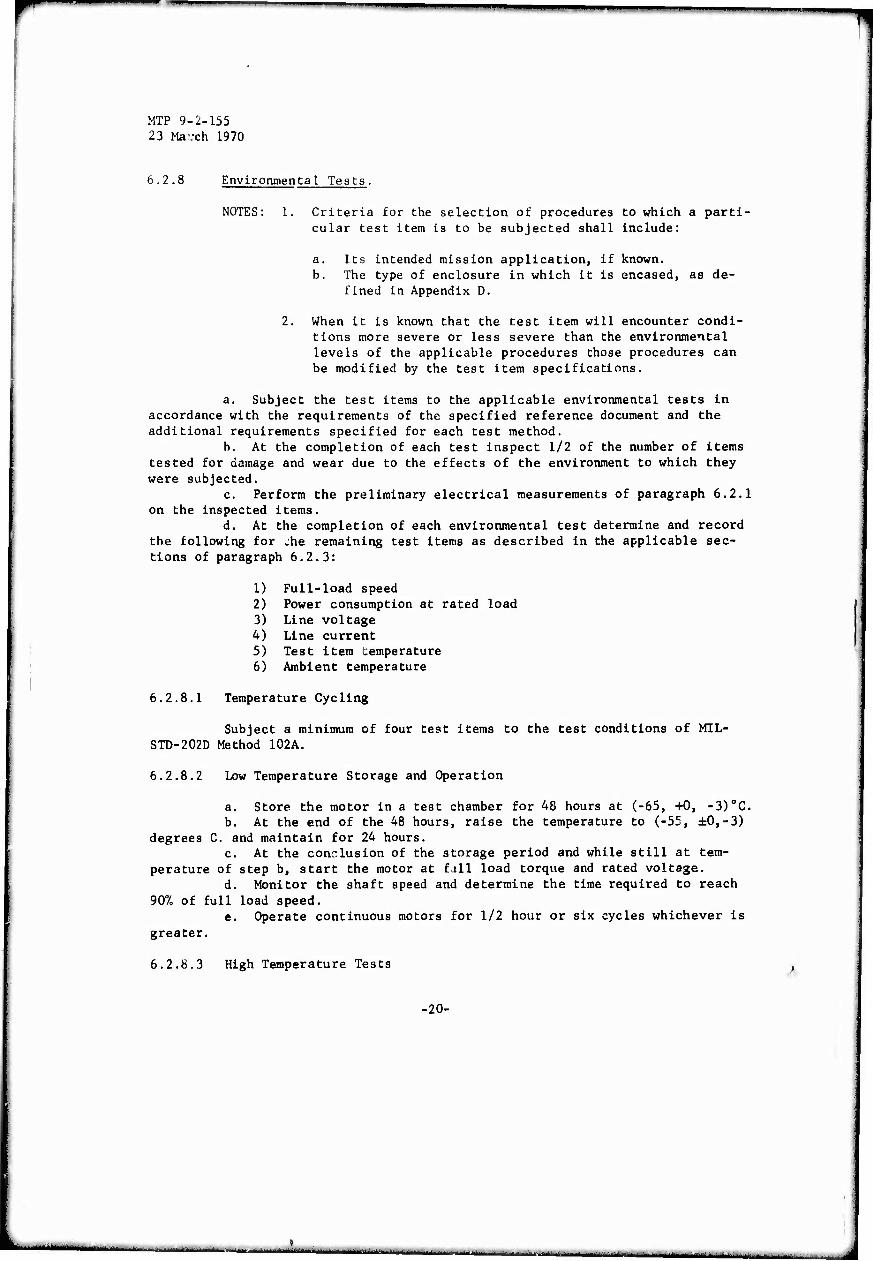
6.2.8 Environmental Tests,
NOTES: 1. Criteria for the selection of procedures to which a parti- cular test item is to be subjected shall include:
a. Its intended mission application, if known. b. The type of enclosure in which it is encased, as de-
fined in Appendix D.
2. When it is known that the test item will encounter condi- tions more severe or less severe than the environmental levels of the applicable procedures those procedures can be modified by the test item specifications.
a. Subject the test items to the applicable environmental tests in accordance with the requirements of the specified reference document and the additional requirements specified for each test method.
b. At the completion of each test inspect 1/2 of the number of items tested for damage and wear due to the effects of the environment to which they were subjected.
c. Perform the preliminary electrical measurements of paragraph 6.2.1 on the inspected items.
d. At the completion of each environmental test determine and record the following for whe remaining test items as described in the applicable sec- tions of paragraph 6.2.3:
1) Full-load speed 2) Power consumption at rated load 3) Line voltage 4) Line current 5) Test item temperature 6) Ambient temperature
6.2.8.1 Temperature Cycling
Subject a minimum of four test items to the test conditions of MIL- STD-202D Method 102A.
6.2.8.2 Low Temperature Storage and Operation
a. Store the motor in a test chamber for 48 hours at (-65, +0, -3)0C. b. At the end of the 48 hours, raise the temperature to (-55, ±0,-3)
degrees C. and maintain for 24 hours. c. At the conclusion of the storage period and while still at tem-
perature of step b, start the motor at fall load torque and rated voltage. d. Monitor the shaft speed and determine the time required to reach
907, of full load speed. e. Operate continuous motors for 1/2 hour or six cycles whichever is
greater.
6.2.8.3 High Temperature Tests '
-20-
■
'^^mmmmamm
MTP 9-2-155 23 March 1970
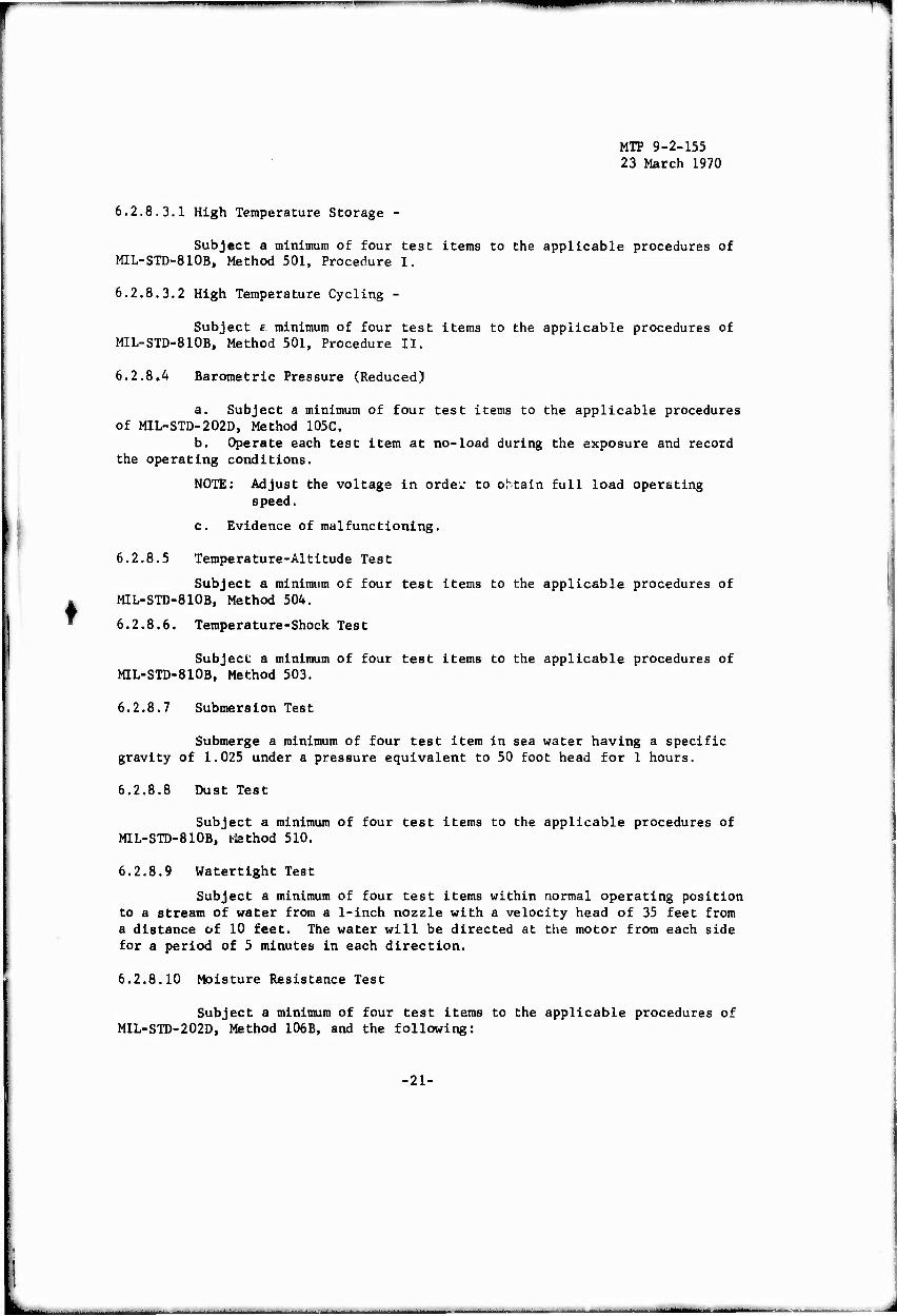
6.2.8.3.1 High Temperature Storage -
Subject a minimum of four teat items to the applicable procedures of MIL-STD-810B, Method 501, Procedure I.
6.2.8.3.2 High Temperature Cycling -
Subject s minimum of four test items to the applicable procedures of M1L-STD-810B, Method 501, Procedure II.
6.2.8,4 Barometric Pressure (Reduced)
♦
a. Subject a minimum of four test items to the applicable procedures of MIL-STD-202D, Method 105C,
b. Operate each test item at no-load during the exposure and record the operating conditions.
NOTE: Adjust the voltage in orde^ to obtain full load operating speed.
c. Evidence of malfunctioning.
6.2.8.5 Temperature-Altitude Test
Subject a minimum of four test items to the applicable procedures of MIL-STD-810B, Method 504.
6.2.8.6. Temperature-Shock Test
Subject a minimum of four test items to the applicable procedures of MIL-STD-810B, Method 503.
6.2.8.7 Submersion Test
Submerge a minimum of four test item in sea water having a specific gravity of 1.025 under a pressure equivalent to 50 foot head for 1 hours.
6.2.8.8 Dust Test
Subject a minimum of four test items to the applicable procedures of MIL-STD-810B, ifethod 510.
6.2.8.9 Watertight Test
Subject a minimum of four test items within normal operating position to a stream of water from a 1-inch nozzle with a velocity head of 35 feet from a distance of 10 feet. The water will be directed at the motor from each side for a period of 5 minutes in each direction.
6.2.8.10 Moisture Resistance Test
Subject a minimum of four test items to the applicable procedures of MIL-STD-202D, Method 106B, and the following:
•21-
i iimiMiiii i
_-,..—
MTP 9-2-155 23 March 1970
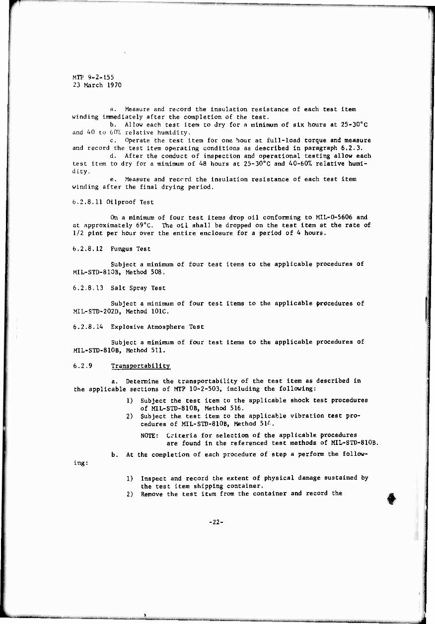
a. Measure and record the Insulation resistance of each test item winding immediately after the completion of the test.
b. Allow each test item to dry for n minimum of six hours at 25-30oC and 40 to 607, relative humidity.
c. Operate, the test item for one hour at full-load torque and measure and record the test item operating conditions as described in paragraph 6.2.3.
d. After the conduct of inspection and operational testing allow each test item to dry for a minimum of 48 hours at 25-30oC and 40-60% relative humi- dity.
e. Measure and record the insulation resistance of each test item winding after the final drying period.
6.2.8.11 Oilproof Test
On a minimum of four test items drop oil conforming to MIL-O-5606 and at approximately 690C. The oil shall be dropped on the test item at the rate of 1/2 pint per hour over the entire enclosure for a period of 4 hours.
6.2.8.12 Fungus Test
Subject a minimum of four test items to the applicable procedures of MIL-STD-810B, Method 508.
6.2.8.13 Salt Spray Test
Subject a minimum of four test items to the applicable procedures of MIL-STD-202D, Method 101C,
6.2.8.14 Explosive Atmosphere Test
Subject a minimum of four test items to the applicable procedures of M1L-STD-810B, Method 511.
6.2.9 Transportability
a. Determine the transportability of the test item as described in the applicable sections of MTP 10-2-503, including the following:
1) Subject the test item to the applicable shock test procedures of M1L-STD-810B, Method 516.
2) Subject the test item to the applicable vibration test pro- cedures of MIL-STD-810B, Method 514.
NOTE: Criteria for selection of the applicable procedures are found in the referenced test methods of M1L-STD-810B.
ing: b. At the completion of each procedure of step a perform the follow-
1) Inspect and record the extent of physical damage sustained by the test item shipping container.
2) Remove the test item from the container and record the
•22-

I
MTP 9-2-155 23 March 1970
following:
a) Broken bracing or damaged packaging materials b) Evidence of shifting of the test item within the container c) Loose, free or broken materials or components
3) Visually Inspect the test item and record any evidence of damage or deterioration.
4) Subject the inspected test item to the applicable electrical measurement procedures of paragraph 6.2.1.
5) Subject the test item to the applicable load test operational procedures of paragraph 6.2.3.
6.2.10 Maintenance
Evaluate the maintenance-related factors of the test item as described in MTP 10-2-507 and MTP 10-2-512 with emphasis on the following:
a. Organizational (0), Direct Support (F), and General Support (H) Maintenance requirements.
b. Operator through General Support Maintenance Literature. c. Repair parts. d. Tools. e. Test and handling equipment. f. Calibration and maintenance facilities. g. Personnel skill requirements, h. Maintainability. 1. Reliability. J. Availability.
6.2.11 Safety
Determine the test item safetly characteristics during the conduct of this MTP by subjecting the test item to the applicable procedures of MTP 10-2-508, including the following:
a. Determine and record the adequacy of the manufacturer's safety instructions, during the conduct of all tests.
b. Prepare a test of all safety devices used on the test item such as overheat or locked rotor protectors.
c. Subject each safety device on the test item to a minimum of two cycles of operation by simulating the type of failure which the device is to detect and record the following for each test run:
1) Safety device/feature tested. 2) Failure which the device is to detect. 3) Proper operation of the device/feature and proper failure
detection
d. Inspect the test item for the following and record any discrep- ancies, as applicable:
-23-
latm
MTP 9-2-155 23 March 1970
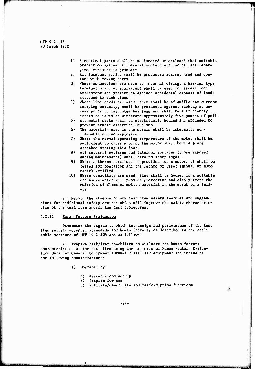
1) Electrical parts shall be so located or enclosed that suitable protection against accidental contact with uninsulated ener- gized circuits is provided.
2) All internal wiring shall be protected against head and con- tact with moving parts.
3) Where connections are made to internal wiring, a barrier type terminal board or equivalent shall be used for secure lead attachment and protection against accidental contact of leads attached to each other.
4) Where line cords are used, '"hey shall be of sufficient current carrying capacity, shall be protected against rubbing at ac- cess ports by insulated bushings and shall be sufficiently strain relieved to withstand approximately five pounds of pull.
5) All metal parts shall be electrically bonded and grounded to prevent static electrical buildup.
6) The materials used in the motors shall be inherently non- flammable and nonexplosive.
7) Where the normal operating temperature of the motor shall be sufficient to cause a burn, the motor shall have a plate attached stating this fact.
8) All external surfaces and internal surfaces (those exposed during maintenance) shall have no sharp edges.
9) Where a thermal overload is provided for a motor, it shall be tested for operation and the method of reset (manual or auto- matic) verified.
10) Where capacitors are used, they shall be housed in a suitable enclosure which will provide protection and also prevent the emission of flame or molten material in the event of a fail- ure.
e. Record the absence of any test item safety features and sugges- tions for additional safety devices which will improve the safety characteris- tics of the test item and/or the test procedures.
6.2.12 Human Factors Evaluation
Determine the degree to which the design and performance of the test item satisfy accepted standards for human factors, as described in the appli- cable sections of MTP 10-2-505 and as follows:
a. Prepare task/item checklists to evaluate the human factors characteristics of the test item using the criteria of Human Factors Evalua- tion Data for General Equipment (HEDGE) Class IIIC equipment and including the following considerations:
1) Operability:
a) Assemble and set up b) Prepare for use c) Activate/deactivate and perform prime functions
-24-
r "I «I
MTP 9-2-155 23 March 1970
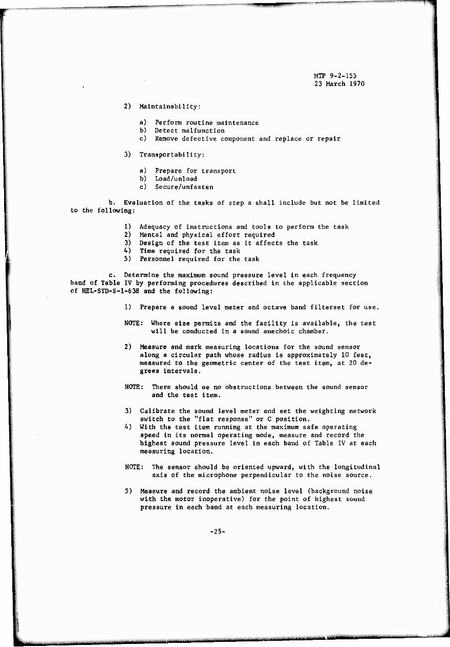
2) Maintainability:
a) Perform routine maintenance b) Detect malfunction c) Remove defective component and replace or repair
3) Transportability:
a) Prepare for transport b) Load/unload c) Secure/unfasten
b. Evaluation of the tasks of step a shall include but not be limited to the following:
1) Adequacy of instructions and tools to perform the task 2) Mental and physical effort required 3) Design of the test item as it affects the task 4) Time required for the task
% 5) Personnel required for the task
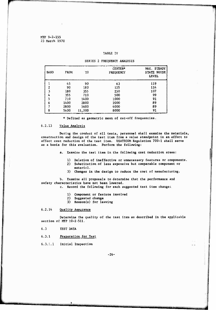
c. Determine the maximum sound pressure level in each frequency band of Table IV by performing procedures described in the applicable section of HEL-STD-S-1-638 and the following:
t 1) Prepare a sound level meter and octave band filterset for use.
NOTE: Where size permits and the facility is available, the test will be conducted in a sound anechoic chamber.
2) Measure and mark measuring locations for the sound sensor along a circular path whose radius is approximately 10 feet, measured to the geometric center of the test item, at 20 de- grees intervals.
NOTE: There should oe no obstructions between the sound sensor and the test item.
3) Calibrate the sound level meter and set the weighting network switch to the "flat response" or C position.
4) With the test item running at the maximum safe operating speed in its normal operating mode, measure and record the highest sound pressure level in each band of Table IV at each measuring location.
NOTE: The sensor should be oriented upward, with the longitudinal axis of the microphone perpendicular to the noise source.
5) Measure and record the ambient noise level (background noise with the motor inoperative) for the point of highest sound pressure in each band at each measuring location.
•25-
ii ii ■ ■ - - —
MTP 9-2-155 23 March 1970
TABLE IV
SERIES 2 FREQUENCY ANALYSIS
CENTER* MAX. STEADY 1 BAND FROM TO FREQUENCY STATE NOISE
LEVEL
1 45 90 63 119 2 90 180 125 114 3 180 355 250 107 4 355 710 500 99 5 710 1400 1000 91 6 1400 2800 2000 89 7 2800 5600 4000 89 8 5600 11,200 8000 91
6.2.13
* Defined as geometric mean of cut-off frequencies,
Value Analysis
During the conduct of all tests, personnel shall examine the materials, construction and design of the test item from a value standpoint in an effort to affect cost reduction of the test item. USATEC0M Regulation 700-1 shall serve as a basis for this evaluation. Perform the following:
a. Examine the test item in the following cost reduction areas:
1) Deletion of ineffective or unnecessary features or components. 2) Substitution of less expensive but comparable component or
material. 3) Changes in the design to reduce the cost of manufacturing.
b. Examine all proposals to determine that the performance and safety characteristics have not been lowered.
c. Record the following for each suggested test item change:
1) Component or feature involved 2) Suggested change 3) Reason(s) for leaving
6.2.14 Quality Assurance
Determine the quality of the test item as described in the applicable section of MTP 10-2-511.
6. 3 TEST DATA
6.3.1 Preparation for Test
6.3.1.1 Initial Inspection
■26-
■ .i — ^ ^^^
MTP 9-2-155 23 March 1970
6.3.1.1.1 Shipping and Packaging Inspections -
Record the followiag:
a. Any non-compliance with the standards of MIL-P-16298 for shipping, preservation and packaging.
b. Marking of shipping package in accordance with MIL-STD-129. c. Evidence of damage or deterioration to packaging or shipping com-
ponents and materials. d. Identification markings. e. All printed matter accompanying the test item and agreement with
the package markings. f. Whether the maintenance package was provided. g. Upon removal of the test item from its shipping carrier or con-
tainer:
t
1) Personnel required. 2) Equipment required. 3) Time required in minutes. 4) Comments regarding the method and materials used to secure
the test item.
6.3.1.1.2 Test Item Inspection -
Record the following, as applicable:
a. Any instance of non-compliance with the marking requirements of MIL-STD-130.
b. Any evidence of defects, damage, and wear in manufacturing, ma- terials, and workmanship including:
1) Treatment of metal surfaces for rust prevention and painting not in accordance with the best commerical practices.
2) For component junctions:
a) Rivets not of a size so as to completely fill the shank holes or have insufficient metal on the flared end to provide adequate fastening strength.
b) Soldering not smooth, sound and clean. c) Welding not free from slag, cracks, fractures and not hav-
ing a smooth, clean appearance. d) Hardware not of sufficient size and strength or not
tightly drawn. e) Seams and joints not having a good fit and alignment and
having sharp edges or burrs.
3) Any doors and covers not operating easily and any defect in mating or alignment.
4) All controls, indicators, access parts and points of attach- ment not marked clearly and legibly, as to their function.
5) Wiring not insulated and protected in accordance with the
-27-
ttuumttmi^tm
MTP 9-2-155 23 March 1970
applicable sections of the National Electrical Code. 6) Electrical cabling and connector damage and Improper mating
of connecting parts.
c. Test item nameplate data and any non-conformance with the minimum nameplate marking requirements of NEMA MG-1-1967.
6.3.1.2 Inventory Check
List any materials or components missing from the test item, Basic Item Issue List, or maintenance test package.
6.3.1.3 Physical Characteristics
Record data collected as described in the applicable sections of MTP 10-2-500 and the applicable motor design characteristics.
6.3.1.4 Operator Training and Familiarization
Record data collected as described in the applicable sections of MTP 10-2-501.
6.3.1.5 Pre-Operational Checks
Record the following:
a. All required test item assembly operations. b. Lubricant check including:
1) Accessibility of lubrication points such as oil holes, grease fittings and grease cups.
2) Lubrication points so designed as to exclude foreign material. 3) Amounts and types of lubricant added, in accordance with main-
tenance Instructions.
c. Any evidence of test item rotor rubbing or binding. d. Any evidence of damage or inadequacy of terminals or leads when
subjected to the applicable pull, bend and torque tests. e. Test item rotor shaft "end-play" in inches. f. Type of test item rotor shaft bearings (sleeve bearings, ball
bearings). g. Air-gap between the rotor and stator iron, in inches, and loca-
tion of each measurement.
6.3.2 Test Conduct
Record all pertinent nameplate data to sufficiently identify each item undergoing test.
6.3.2.1 Preliminary Electrical Measurements
•28-
— ■- ir --
MTP 9-2-155 23 March 1970
Retain all installation photographs.
6.3.2.1.1 Continuity and Grounding Checks -
Record verification of the following for the test item:
a. Each power lead is ungrounded. b. All external parts including mounting bases, terminal enclosures
and other exposed metal parts are all electrically connected. c. Earth or building ground lead, connected, effectively grounds the
test item. d. Electrical continuity of each winding. e. Pertinent data from repetitive surge tests, if applicable.
6.3.2.1.2 Direct-Current Resistance -
Record the direct-current resistance data for each test item winding, collected as described in the applicable sections of IEEE Publication No. 118.
6.3.2.1.3 Insulation Resistance -
Record the following, as applicable:
a. Insulation resistance data for each test item winding, collected as described in the applicable sections of IEEE Publication No. 43.
b. Mean ambient temperature during insulation resistance measure- ments.
c. For wound-rotor induction motors:
1) Direct-current resistance between collector rings in ohms. 2) Temperature of the motor windings in 0C.
6.3.2.1.4 Dielectric Strength -
Record the dielectric strength data for each test item current, col- lected as described in the applicable sections of IEEE Publications No. 4 and No. 51.
6.3.2.2 Dynamic Balance
Record the following as applicable:
a. Mounting pad original nominal thickness, in inches. b. Mounting pad compression after test item installation, in inches. c. Maximum amplitude of bearings having vibration, in inches. d. Direction of maximum vibration. e. Location on the housing where the measurements were made. f. For the balancing operation:
1) Amount of key required to achieve dynamic balance. 2) Operating speed in rpm.
-29-
..-.,,...
MTP 9-2-155 23 March 1970
3) Maximum peak-to-peak amplitude of vibration after balancing, in inches.
4) Direction of maximum amplitude.
6.3.2.3 Operational Performance
a. Record test data on forms of the types described in the applicable IEEE test procedure.
b. Record the direction of rotation of the test item shaft, if re- quired.
c. Retain and identify all photographs..
6.3.2.3.1 Direct-Current Motors -
Record the test item performance data, collected as described in the applicable sections of IEEE No. 113, including the following.
a. Data from static tests including:
1) Field coil potential drop, in volts 2) Field coil polarity
lowing; b. Data from complete test series for the determination of the fol-
1) Magnetic saturation curve 2) Successful commutation 3) Regulation of speed, including:
a) No-load to rated-load b) Rated-load to overload
4) Efficiency at required loads in percent
NOTE: Record appropriate data for the method selected as directed in IEEE No. 113.
5) Load characteristics for, as applicable:
a) Fractional-horsepower motors b) Integral-horsepower motors
6) Temperature rise of the following at rated load(s), as ap- plicable:
a) Armature windings b) Armature core c) Shunt field d) Series field e) Commutation pole field f) Commutator bars g) Collector rings
-30-
■mp
MTP 9-2-155 23 March 1970
6.3.2.3.2 Alternating-Current Motors -
a. Record polyphase induction motor performance data, collected as described in the applicable sections of IEEE No. 112A, including the following as applicable:
1) Routine test data for:
a) No-load characteristics at rated voltage and frequency. b) Locked-rotor characteristics at rated voltage. c) Wound-rotor open-circuit voltage, for wound-rotor type
test items.
2) Data from the complete test series for the determination of:
a) Efficiency at required loads at rated voltage and fre- quency in percent.
NOTE: Record appropriate data for the method selected as directed in IEEE 112A.
b) Rated-load slip in percent. c) Power factor at the required loads in percent. d) Temperature rise of the following at rated-load; as ap-
plicable:
(1) Stator core (2) Stator windings (3) Rotor core (4) Rotor windings (5) Commutator bars (6) Collector rings
e) Speed-torque characteristics for the speed range from zero to synchronous speed including:
(1) Starting torque (2) Pull-up torque (3) Breakdown torque (4) Load-torque
NOTE: Care must be taken to record all data in units compatible for making the required calculations.
b. Record single phase induction motor performance data, collected as described in the applicable sections of IEEE No. 114, including thJ follow- ing, as applicable:
1) Routine test data for the determination of:
a) No-load characteristics at rated voltage and frequency.
-31-
ÜlllMllfiMi" : - ......._■■
MTP 9-2-155 23 March 1970
b) Locked rotor characteristics at rated voltage.
2) Data from complete test series for the determination of:
a) Efficiency at required loads at rated voltage and fre- quency in percent.
NOTE: Record appropriate data for the method selected as directed in IEEE 114.
b) Rated-load slip in percent. c) Power factor at the required loads la percent. d) Speed-torque characteristics for the speed range from
zero to synchronous speed including:
(1) Switching torque (2) Pull-up torque (3) Breakdown torque (4) Load torque
e) Temperature rise of the following at rated load:
(1) Stator core (2) Stator windings (3) Rotor core (4) Rotor windings
f) Apparent efficiency at the required loads in percent.
c. Record synchronous motor performance data, collected as described in the applicable sections of IEEE No. 115, including the following, as appli- cable:
1) Miscellaneous test data for the determination of:
a) Short-circuited field turns b) Field pole polarity c) Phase sequence
2) Efficiency at required loads, in percent.
NOTE: Record appropriate data for the method selected as directed in IEEE 115.
3) Load excitation characteristics under specified conditions. 4) Per unit voltage regulation. 5) Power factor at required loads in percent. 6) Temperature rise at rated-load(s) during running or at shut-
down by the selected method. 7) Speed-torque characteristics for specified conditions and
method of measurement including:
a) Locked-rotor characteristics
-32-

r —
i
MTP 9-2-155 23 March 1970
b) Pull-up torque c) Nominal pull-in torque d) Pull-out torque
8) Synchronous machine quantities and sudden short circuit data as required by the selected test methods.
6.3.2.4 Inclined Operation
a. Record the following for each inclined operation as applicable:
1) Test item installation description (shaft inclined 15 degrees fron end low, etc.)
2) During each operational period:
a) Dynamic balance data, collected as described in paragraph 6.2.2.
b) Any evidence of pounding or grinding at the bearings. c) Evidence of lubrication oil-rings striking against or rub-
bing the sides of the oil well. d) Evidence of oil-ring "dancing" or pronounced irregularity
of oil-ring movement. e) Any slinging of oil into the motor by the shaft. f) Line voltage (AC/DC). g) Line current in amperes. h) Power consumption at rated-load in watts. 1) Full-load speed, in rpm. j) Ambient temperature in "C.
3) At the completion of each operation:
a) Test item temperatures as required during temperature rise tests, in 0C.
b) Bearing/bearing housing temperature in 0C. c) Lubricating oil temperature in 0C. d) Duration of the test operation, in minutes.
b. Retain all photographs.
6.3.2.5 Mechanical Shock and Vibration Tests
6.3.2.5.1 Shock -
a. Record the following for each test item, as applicable;
1) Shock data, collected as described in MIL-STD-202D, Method 205C or Method 207A.
2) Test method used (205C or 207A) 3) Nomenclature 4) Model number and serial number
-33-
MT? 9-2-155 23 March 1970
b. Record the following for test items inspected at tie completiün of
testing:
i) Serial number 2) Evidence of damage 3) Location of damage
c. Record the following for test items subjected to operability
tosts at the completion of testing:
1) Serial number. 2) Evidence of ineffectiveness. 3) Operational data collected as described in the applicable
sections of paragraph 6.2.3.
6.3.2.5.2 Vibration -
Record the following for each test item, as applicable:
a. Nomenclature . b. Model number and serial number. c. Vibration data, collected as described in the applicable sections
of MIL-STD-202D, Method 201A, including the following as applicable:
1) Test conditions including:
a) Total amplitude of simple harmonic motion in inches. b) Duration of 10-55 cycle frequency range variation, in
seconds. c) Direction of vibration during each two-hour vibrational
period. d) No-load speed of test item during vibrational period oper-
ation, in rpm.
d. At the completion of vibration testing:
1) Operational data, collected as described in applicable sec-
tions of paragraph 6.2.3. 2) Line power consumption during operation. In watts. 3) Any evidence of loose components or hardware.
6.3.2.6 Electromagnetic Interference
Record electromagnetic Interference data, collected as described In
the applicable sections of MIL-STD-462.
6.3.2.7 Durability
Record data, collected as described in the applicable sections of
MTP 9-2-503 and the following:
.34-
,...,_.M^^^,.--^^.,.^.,JM.-^J— -,. ■,., . . - -.—■—. —
r
test:
MTP 9-2-155 23 March 1970
a. At the start of the test:
1) Date. 2) Starting tine in hours and minutes. 3) Duty cycle description (continuous, intermittent). 4) Applied voltage. 5) Applied torque in Ib-ft, oz-ft, or oz.-inches, as applicable. 6) Appropriate quantities for determining the motor winding tem-
perature rise (winding temperatures in 0C or winding resis- tance in ohms).
b. At the completion of each 100-hour elapsed time period during the
1) Input power in watts. 2) FuU-load speed, in rpm. 3) Motor case temperature, in CC. 4) Ambient air temperature, in "C. 5) Appropriate quantities for determining the motor winding tem-
perature rise (temperature in 0C or winding resistance in ohms) 6) Elapsed time from the start of the test, in hours.
c. At the completion of the cest:
1) Duration of the test in hours. 2) Portion of the duty cycle utilized in percent. 3) Post-test inspection results for any signs of wear and
potential equipment failures including, as applicable:
a) Damage to any component, material, or surface finish b) Loosening of hardware c) Excessive housing temperatures in 0C d) Lubricant or fluid leakage e) Insulation deterioration
d. For any defect found during the post-test inspection:
1) Nature of the defect 2) Location of the defect 3) Cause of the defect, if known 4) Recommended remedy
6.3.2.8 Environmental Test
Record the following for each test item subjected to environmental test procedures at the conclusion of the test:
a. Nomenclature. b. Model number. c. Serial number. d. Type of enclosure (open, drip proof, splash proof, etc.) e. Evidence of damage produced by the environmental test.
•35-
L
MTP 9-2-155 23 March 1970
f. Preliminary electrical measurement data collected as described in paragraph 6.2.1.
g. Operational data collected as described in the applicable sections of paragraph 6.2.3, including:
1) Full-load speed 2) Power consumption at rated load 3) Line voltage, in volts 4) Line current, in amps 5) Test item temperature, in "C 6) Ambient temperature, in "C
6.3.2.8.1 Temperature Cycling -
Record temperature cycling storage data, collected as described in the applicable sections of MIL-STD-202D.
6.3.2.8.2 Low Temperature Storage -
Record the following:
a. Starting torque, in lb.-ft. b. Time required for shaft to reach 907° of full-load speed c. Duration of the test item operation, in minutes d. Type of duty cycle (continuous or intermittent)
6.3.2.8.3 High Temperature Tests -
Record the following:
a. High temperature storage data collected as described in Method 501, Procedure I of MIL-SPD-SIOB.
b. High temperature cycling data collected as described in Method 501, Procedure II, of MIL-STD-810B.
6.3.2.8.4 Barometric Pressure (Reduced) -
Record altitude data collected as described in Method 105C, of MIL- STD-202D, and the following:
a. Operating conditions during the test b. Operating voltage used c. Evidence of malfunctioning
6.3.2.8.5 Temperature-Altitude Test -
Record temperature-altitude data collected as described in Method 504, of MIL-STD-810B.
6.3.2.8.6 Temperature-Shock Test -
-36-
r w^^m—mmim
mmn^^^^— ■*' '
>■
MTP 9-2-155 23 March 1970
Record temperature-shock data collected as described in Method 503 of MIL-STD-810B.
6.3.2.8.7 Submersion Test -
Record deviation from specified test conditions, if any.
6.3.2.8.8 Dust Test -
Record dust test data collected as described in Method 510 of MIL- STD-810B.
6.3.2.8.9 Watertight Test -
Record deviation from specified test conditions, if any.
6.3.2.8.10 Moisture Resistance Test -
Record moisture resistance test data collected as described in Method 106B of MIL-STD-202D and the following:
a. Insulation resistance of each test item winding immediately after the completion of the test.
b. For the first drying period:
1) Length of drying period, in hours 2) Ambient temperature, in 0C 3) Relative humidity, in percent
c. At the completion of the first drying period:
1) Inspection data for 1/2 of the items tested. 2) Electrical data for the inspected items, collected as describ-
ed In the applicable sections of paragraph 6.2.1. 3) Operational data for the remaining items collected as de
scribed in the applicable sections of paragraph 6.2.3, in- cluding:
a) Rated-load speed in rpm b) Power consumption at rated-load in watts c) Line voltage (AC/DC) d) Line current, in amps e) Duration of operation, in minutes
d. For the final drying period:
1) Length of drying period, in hours 2) Ambient temperature, in 0C 3) Relative humidity, in percent
e. Insulation resistance of each winding after final drying period.
•37-
MTP 9-2-155 23 March 1970
6.3.2.8.11 Oilproof Test -
Record deviation from the specified test conditions, if any.
6.3.2.8.12 Fungus Test -
Record fungus test data collected as described in Method 508 of MIL- STD-810B.
6.3.2.8.13 Salt-Spray Test -
Record salt-spray test data collected as described in Method 101C, of M1L-STD-202D.
6.3.2.8.14 Explosive Atmosphere Test -
Record explosive atmosphere test data collected as described in Method 511 of MIL-STD-810B.
6.3.2.9 Transportability
a. Record transportability data, collected as described In the ap- plicable sections of MTP 10-2-503, and the following:
1) Shock test data, as required by the applicable procedures of MIL-STD-810B, Method 516.
2) Vibration test data, as required by the applicable procedures of MIL-STD-810',, Method 514.
b. Record the fol1 at the completion of each test procedure:
1) Test pe: tormed (shock, vibration, etc). 2) Extent of damage sustained by the test item shipping con-
tainer.
c. Record the following at the completion of the test item removal from the shipping container, as applicable:
1) Broken bracing 2) Evidence of shifting of the test item within the container 3) Loose, free or broken materials or components 4) Any evidence of damage or deterioration to the test item
d. Record electrical data collected as described in the applicable sections of paragraph 6.2.1.
e. Record performance data, collected as described in the appli- cable sections of paragraph 6.2.3.
6.3.2.10 Maintainability
•<»■■
•38-
■^■■i^«^^^^^ < ■'■
MTP 9-2-155 23 March 1970
Record data collected as described in the applicable sections of MTP 10-2-504 and MTP 10-2-512,
6.3.2.11 Safety
Record safety data collected as described in the applicable sections of MTP 10-2-508, and the following:
a. Adequacy of the manufacturer's safety instructions.
b. Record the following in tabular form:
1) A list of all safety devices used on the test item 2) Two cycle test run results for each device listed including:
a) Run number b) Type of failure which each device is to detect
3) Indication of proper operation of the device/feature and proper failure detection.
c. Record any test item safety discrepancies found during the safety inspection.
d. Record the absence of any test item safety features and sugges- tions to improve the safety characteristics of the test item and/or the test procedures.
6.3.2.12 Human Factors Evaluation
a. Record data collected as described in the applicable sections of MTP 10-2-505.
b. Retain all checklists for the test item and its related components for the HEDGE test functions given.
c. Record pertinent sound level measurement data, collected as de- scribed in the applicable sections of HEL-STD-S-1-63B, including the following:
1) Measurement facility utilized (sound anechoic chamber, test room etc.).
2) Sound sensor locations with respect to the test item includ- ing:
a) Distance from the test item center, in feet. b) Clockwise location on the circle from the front center of
the test item, in degrees.
3) Ambient noise level at each sensor location in db with:
a) Test item inoperative b) Test item operating at its maximum safe speed
6.3.2.13 Value Analysis
-39-
MTP 9-2-155 23 March 1970
Record the following for each suggested test item change:
a. Component or feature involved b. Suggested change c. Reason(s) for the suggestion
6.3.2.14 Quality Assurance
Record data collected as described in the applicable sections of MTP 10-2-511.
6.4 DATA REDUCTION AND PRESENTATION
6.4.1 General
a. Data collected from all subtests covered by referenced MTP's, and other documents, shall be summarized, tabulated, and compared with the technical performance characteristics specified in the QMR, SDR and applicable standards, and evaluated according to the referenced procedures. Appropriate charts, graphs and other illustrative material shalL- be utilized to present the results in a clear manner.
Calculations shall be performed as specified by the referenced docu- ments, wherever applicable, and all photographs, motion pictures, and illus- trative material shall be suitably identified.
b. All data not evaluated as described in a. above, or in paragraphs 6.4.2 through 6.4.9 shall be tabulated or summarized as appropriate and com- pared with test item specifications whenever possible or with specified standards.
c. A Safety Release Recommendation shall be submitted in accordance with USATECOM Regulation 385-6 based on the data collected related to safety.
6.4.2 Preliminary Electrical Measurements
a. Present the data from all measurements in tabular form and com- pare the values for insulation resistance and dielectric strength with those obtained from the same measurements made after the operability and durability tests specified and with those taken in conjunction with the environmental and transportability tests conducted.
b. The values for insulation resistance and dielectric strength shall also be compared to the minimum allowable values specified for the respective test item circuits.
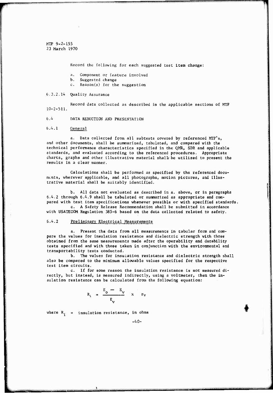
c. If for some reason the insulation resistance is not measured di- rectly, but instead, is measured indirectly, using a voltmeter, then the in- sulation resistance can be calculated from the following equation:
E — E Ri = -2 X x rv
E v
where R. = insulation resistance, in ohms
-40-
J

r
t MTP 9-2-155 23 March 1970
Eo = source potential, in volts
Ev = voltmeter reading, in volts
rv = Voltmeter resistance, in ohms
d. Compute winding resistances corrected to nominal ambient tempera- tures, whenever required, as follows:
where:
- Rv, K + tc
K + th
Re = winding resistance corrected to ambient temperatures, in ohms
Rh = winding resistance, measured at measured winding temperature, in ohms
tc = Ambient temperature, in "C
tjj = Winding temperature, in 0C
K = 234.5 for 100% volume conductivity for copper
NOTE: All performance determination (paragraphs 6.2.3. and 6.4.4.) shall be corrected to 250C ambient, unless otherwise specified in the same manner as the resistances are to be corrected.
6.4.3 Dynamic Balance
Compare the maximum amplitude of vibration with the maximum allow- able as shown In Table III and as described In NEMA MG-1-1967.
6.4.4 Operational Performance
-ÄF
a. Data shall be presented In the form described by the applicable IEEE procedure.
b. Data reduced and tabulated to define the test Item performance characteristics shall be compared with the allowable standards given In the applicable sections of MG-1-1967.
c. Measured test Item no-load characteristics shall be compared to the specified requirements and standards and discrepancies noted.
d. Motor characteristic curves shall be plotted In accordance with NEMA MG-1-1967, paragraph 12.07.
NOTE: United for quantities used In computations and for the plott- ing of test Item characteristics curves shall be as follows, In the applicable cases:
1. Current in amperes 2. Voltage in volts or 7» of rated voltage 3. Torque in pound-feet, ounce-feet, ounce-inches, synchro-
nous HP, or % of torque at rated HP.
■41-
i
MTP 9^2-155 23 March 1970
4. Speed in rpm, % of synchronous speed, or 7» of speed at rated HP.
5. Temperature in 0C. 6. Output in watts, horsepower, or °L of rated horsepower. 7. Efficiency in %. 8. Power factor in %.
e. Test item duty cycles shall be considered in the calculation of operating temperatures from temperature rise data, and defined as follows:
1) Continuous operation at constant load and speed. 2) Short cycles (10 minutes or less) where the temperature re-
mains essentially constant. 3) Cycles consisting of long periods of operation (several hours
or longer) at each speed and load condition. 4) Cycles wherein appreciable temperature variation (heating
and cooling) occurs.
6.4.4.1 Direct-Current Motors
a. Perform all computations required for the test item performance evaluation as described in the applicable sections of IEEE No. 113.
b. Tabulate the computed data in a form facilitating comparison and correlation with measured parameters and applicable standards/specifications.
6.4.4.2 Alternating-Current Motors
6.4.4.2.1 Polyphase Induction Motors -
a. Perform all computations required for the test item performance evaluation as described in the applicable sections of IEEE No. 112A.
b. Tabulate the computed data in a form facilitating comparison and correlation with measured parameters and applicable standards/specifications.
6.4^4.2.2 Single-Phase Motors -
a. Perform all computations for the test item performance evaluation as described in the applicable sections of IEEE No. 114.
b. Tabulate the computed data in a form facilitating comparison and correlation with measured parameters and applicable standards/specifications.
6.4.4.2.3 Synchronous Motors -
a. Perform all computations required for the test item performance evaluation as described in the applicable sections of IEEE No. 115.
b. Tabulate the computed data in a form facilitating comparison and correlation with measured parameters and applicable standard/specifications.
6.4.5 Inclined Operation
Tabulate the results of all test runs and compare the results with
-42-
— — ■ ■ ■— ■ ■■--1

t MTP 9-2-155 23 March 1970
those obtained from:
a. Dynamic balance tests b. Operational tests at rated-speed and rated-load
6.4.6 Electromagnetic Interference
6.4.6.1 Radiated Interference
Perform the following:
a. Prepare a table from measurement data corrected for ambient inter- ference, including the following:
1) Measurement locations 2) Applicable frequency bands 3) Highest reading in each band 4) Respective frequencies of the highest readings
NOTE: Use the applicable curves from MIL-STD-461 to determine the maximum allowable limits.
b. Circle those readings which exceed the maximum allowable values.
6.4.6.2 Line Conducted Interference
Perform the following:
a. Prepare a table from measurement data, corrected for ambient inter- ference, including the following:
1) Measurement locations 2) Applicable frequency bands 3) Highest reading in each band 4) Respective frequencies of the highest readings
NOTE: Use the applicable curves from MIL-STD-461, to determine the maximum allowable limits.
b. Circle those readings which exceed the maximum allowable values.
6.4.7 Durability
a. Prepare a table presenting all data recorded during durability testing in chronological order.
b. Circle any data values which show an undue change during the durability testing.
c. Compare the computed temperature rise of the test item during durability testing with the allowable rise described by the appropriate table in NEMA MG-1-1967, and for the appreciable insulation class, as described in Appendix G.
-43-

MIT 9-2-155 23 March 1970
d. Compare the temperature rise of the test item determined during durability testing with that determined during performance testing.
e. Present a summary of all test item defects and malfunctions occuring during durability testing and of remedial action taken.
6.4.8 Environmental Tests
a. Process and present the electrical and performance data recorded during and after the conduct of each applicable environmental test as described by paragraphs b.4.2 and 6.4.4, and compare results obtained to determine the effects of each environment on the test item.
b. Complete a summary based on the compared data to describe the ability of the test item to withstand severe environments and the effectiveness of its enclosure.
6.4.9 Human Factors Evaluation
Summarize the human factors data as required and present the noise level data as described by HEL-STD-S-1-63B, and as follows:
a. Prepare a table showing sound level measurement locations, the highest noise level readings in each band, and the ambient noise level corre- sponding to each measurement.
b. Include a column for corrected noise level measurements to be completed in the following manner:
1) If the difference between the measured noise level and the ambient noise level is three decibels or less, mark the cor- rected measurement "indeterminate."
2) If Che difference is between four and ten decibels use cor- rections as shown in Table V.
3) If the difference is greater than ten decibels, no corrections are necessary.
TABLE V Cot Soi
rect ind 1
:ions for Ambient i Jressure Levels
Difference in decibels between sound pressure level measured with sound source operating and ambient sound pressure level alone. 4 5 6 7 8 9 10 Correction, in decibels, to be subtracted from sound pressure level measured with sound source operating to obtain sound pressure level due to sound
Isource alone
2 2 1.7 1.3 1 0 0 8 0 6 0.4
4) Circle those readings which are out of limit by consulting Table IV which contains the allowable limits as given by HEL- STD-S-1-63B, Maximum Noise Level for Army Materiel Equipment.
-44-
in—I—I -
•mmm
*
MTP 9-2-155 23 March 1970
GLOSSARY
1. Continuous Duty: A requirement of service that demands operation at a sub- stantially constant load for an indefinitely long time.
2. Intermittent Duty: A requirement of service that demands operation for alternate intervals of:
a. Load and no-load b. Load and rest c. Load, no-load, and rest
3. Varying Duty: A requirement of service that demands operation at loads and for intervals of time, both of which may be subject to wide variation.
4. Short-time Duty: A requirement of service that demands operation at a sub- stantially constant load for a short and definitely specified time.
5. Rating: The rating of a motor shall consist of the output together with any other characteristics, such as, speed, voltage and current, assigned to it by the manufacturer.
6. Efficiency: The efficiency of a motor is the ratio of its useful power output, to its total power input and is usually expressed in percentage.
7. Power Factor; The power factor of an alternating-current motor is the ratio of the kilowatt input (or output) to the kva input (or output) and is usually expressed as a percentage.
8. Service Factor: The service factor of an alternating-current motor is a multiplier which, when applied to the rated horsepower, indicates a per- missible horsepower loading which may be carried under the conditions specified for the service factor (see MG 1-14,34.a).
9. Secondary Voltage of Wound-Rotor Motors: The secondary voltage of wound- rotor motors is the open-circuit voltage at standstill, measured across the slip rings, with rated voltage applied on the primary winding.
10. Full-Load Torque; The full-load torque of a motor is the torque necessary to produce its rated horsepower at full-load speed. In pounds at a 1-foot radius, it is equal to the horsepower times 5252 divided by the full-load speed.
11. Locked-Rotor Torque (Static Torque); The locked-rotor torque of a motor is the minimum torque which it will develop at rest for all angular positions of the rotor, with the rated voltage applied at rated frequency.
12. Locked-Rotor Current; The locked-rotor current of a motor is the steady- state current taken from the line with the rotor locked and with rated voltage (and rated frequency in the case of alternating-current motors) applied to the motor.
■ ■" - I _J^J»M^^.^MM«ui
MTP 9-2-155 23 March L970
13. Breakdown Torque: The bn.akdown torque of a motor ia the maxtmum torque which it will develop witn rated voltage applied at rated frequency, with- out an abrupt drop in spied.
1/+- Full-Up Torque: The pull-up torque of an alternating-current motor is the minimum torque developed by the motor during the period of acceleration from rest to the speed at which breakdown torque occurs. For motors which do not have a definite breakdown torque, the pull-up torque is the minimum torque developed up to rated speed.
15. Pull-Out Torque: The pull-out torque of a synchronous motor is the maximum sustained torque which the motor will develop at synchronous speed with rated voltage applied at rated frequency and with normal excitation.
16. Pull-in Torque: The pull-in torque of a synchronous motor is the maximum constant torque under which the motor will pull its connected inertia load into synchronism, at rated voltage and frequency, when its field excitation is applied. The speed to which a motor will bring its load depends on the power required to drive it and whether the motor can pull the load into step from this speed depends on the inertia of the revolving parts, ao tnat the pull-in torque cannot be determined without having the Wk2 as well as the torque of the load.
17. Starting Capacitance for a Capacitor Motor: The starting capacitance for a capacitor motor is the total effective capacitance in series with the starting winding under locked-rotor conditions.
18. Ambient Temperature: The temperature of the surrounding cooling medium, such as gas or liquid which comes into contact with the heated parts of the motor.
NOTE: Ambient temperature is commonly known as "room temperature" in connection with air-cooled apparatus not provided with artificial ventilation.
19. Thermal Protector: A protective device for assembly as an intrgral part of the machine and which, when properly applied, protects the machine against dangerous overheating due to overload and, in a motor, failure to start.
NOTE: The thermal protector may consist of one or more temperature sensing elements integral with the machine and a control de- vice external to the machine.
When a motor is rated more than one horsepower, a number preceding or fol- lowing the words "thermally protected" (on the motor nameplate) shall be used to indicate the kind of protection provided as follows:
a. Type 1 - The thermal protector provides operating overheating protec- tion for the motor due to overload or failure to start, and overcurrent
II
n
MTP 9-2-155 23 March 1970
protection for all elements of the motor branch circuit when these ele- ments are selected according to Article 430 of the National Electrical Code.
b. Type 2 - The thermal protector provides operating overheating protec- tion for the motor due to overload or failure to start and overcurrent protection for all elements of the motor branch circuit, except the controller, when these elements are selected according to Article 430 of the National ELectrical Code.
c. Type 3 - The thermal protector provides operating overheating protec- tion for the motor due to overload or failure to start. Other elements of the motor branch circuit may require increased rating or separate protection. Obtain data from the motor manufacturer for selecting other circuit components.
20. Frame Number: A system for designating the dimension(s) of the motor frame, depending on the type of motor involved and its application. (Ste Part II of NEMA MG-1, 1967).
21. Front (of Motor): The end of the motor opposite to the coupling.
22. Back (of Motor): The end of the motor which carries the coupling or driving pulley.
Ill
■ .« - A
m^mmm
MTP 9-2-155 23 March 1970
THIS PAGE INTENTIONALLY LEFT BLANK
IV
■
^am
MTP 9-2-155 23 March 1970
1.
1.1
APPENDIX A
MOTOR CLASSIFICATIONS (Indicated references are to NEMA MG-1-1967)
CLASSIFICATION ACCORDING TO SIZE
FRACTIONAL HORSEPOWER MOTORS
A fractional horsepower motor is either (1) a motor built in a frame which has a 2-digit frame number in accordance with par. A of MG 1-11.01 or (2) a motor built in a frame smaller than that frame of an integral-horsepower motor (see MG 1-1.02) which has a continuous rating of 1 horsepower, open con- struction, at 1700-1800 rpm.
1.2 INTEGRAL HORSEPOWER
a. An alternating-current integral-horsepower motor is a motor (1) built in a frame which has a 3-digit frame number in the 680 and smaller series in accordance with par. B of MG 1-11.01 and (2) built in a frame having an open continuous rating of 1 horsepower at 1700-1800 rpm or in a larger frame but no larger than the frame required for the ratings given in par. D of MG 1-10.32 for induction motors.
b. A direct-current integral-horsepower motor is either (1) a motor built in a frame which has a 3-digit frame number in the 680 and smaller series in accordance with par. B of MG 1-11.01 or (2) a motor built in a frame having an open continuous rating of 1 horsepower at 1700-1800 rpm or in a larger frame but no larger than the frame required for the ratings given in par. B of MG 1-10.60 for direct-current motors.
2.1
CLASSIFICATION ACCORDING TO APPLICATION
GENERAL PURPOSE ALTERNATING-CURRENT MOTORS
A general-purpose alternating-current motor is an induction motor, rated 200 horsepower and less, which incorporates all of the following:
a. Is of open construction. b. Is continuously rated. c. Has a service factor in accordance with MG 1-12.47 or MG 1-12.47.a. d. Has a Class A insulation system with a temperature rise as speci-
fied in MG 1-12.41 or has a Class B insulation system with a temperature rise as specified in MG 1-12.42.
It is designed in standard ratings with standard operating charac- teristics and mechanical construction for use under usual service conditions without restriction to a particular application or type of application.
2.2 INDUSTRIAL DIRECT-CURRENT MOTORS
a. An industrial direct-current motor is an integral-horsepower
A-l
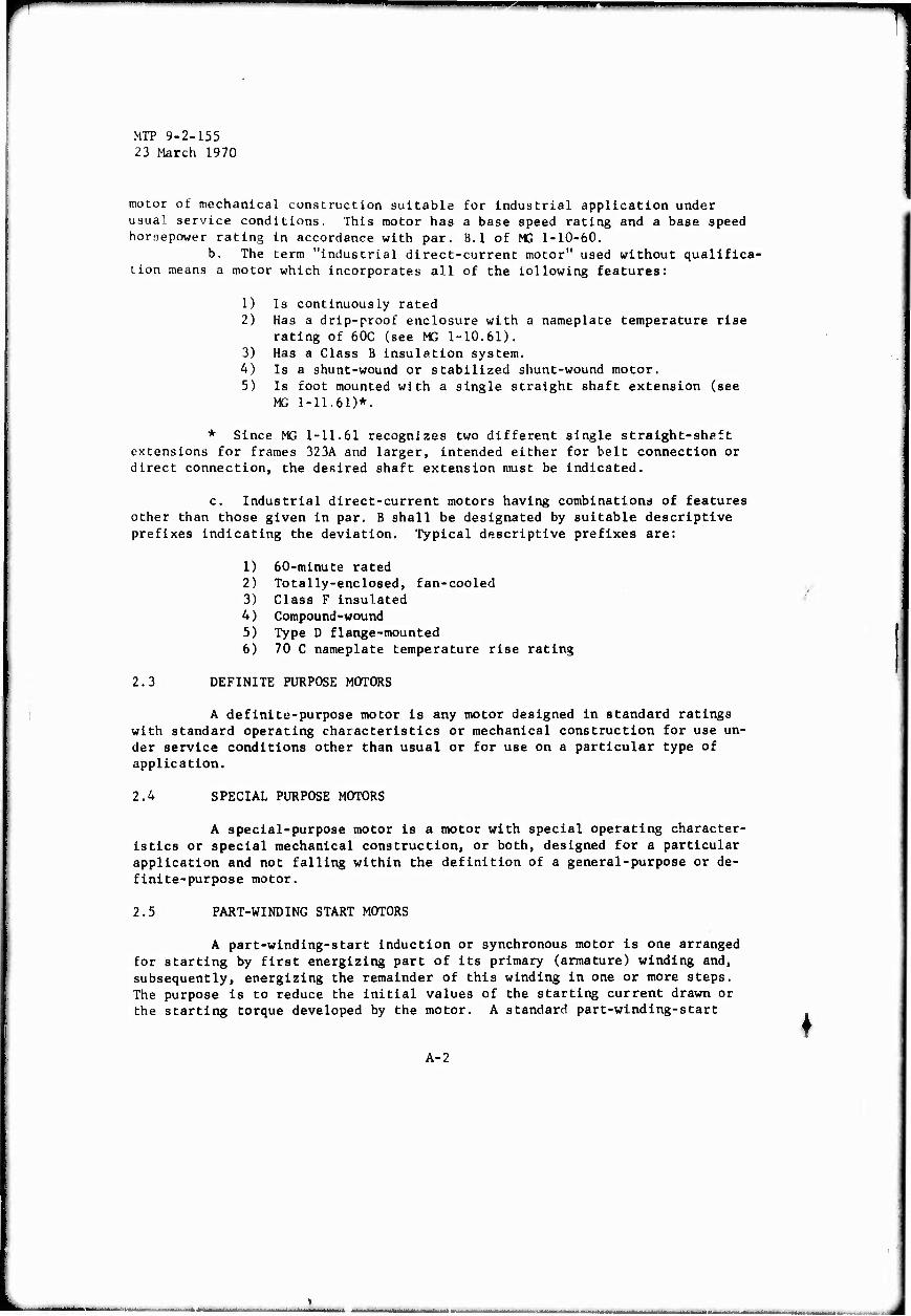
MIT 9-2-155 23 March 1970
motor of mechanical construction suitable for industrial application under usual service conditions. This motor has a base speed racing and a base speed horaepower rating in accordance with par. B.1 of MS 1-10-60.
b. The term "industrial direct-current motor" used without qualifica- tion means a motor which incorporates all of the lollowing features:
1) Is continuously rated 2) Has a drip-proof enclosure with a nameplate temperature rise
rating of 60C (see MG 1-10.61). 3) Has a Class B insulation system. 4) Is a shunt-wound or stabilized shunt-wound motor. 5) Is foot mounted with a single straight shaft extension (see
MG 1-11.61)*.
* Since MG 1-11.61 recognizes two different single stralght-sheft extensions for frames 323A and larger, intended either for belt connection or direct connection, the desired shaft extension must be indicated.
c. Industrial direct-current motors having combinations of features other than those given in par. B shall be designated by suitable descriptive prefixes indicating the deviation. Typical descriptive prefixes are:
1) 60-minute rated 2) Totally-enclosed, fan-cooled 3) Class F insulated 4) Compound-wound 5) Type D flange-mounted 6) 70 C nameplate temperature rise rating
2.3 DEFINITE PURPOSE MOTORS
A definite-purpose motor is any motor designed in standard ratings with standard operating characteristics or mechanical construction for use un- der service conditions other than usual or for use on a particular type of application.
2.4 SPECIAL PURPOSE MOTORS
A special-purpose motor is a motor with special operating character- istics or special mechanical construction, or both, designed for a particular application and not falling within the definition of a general-purpose or de- finite-purpose motor.
2.5 PART-WINDING START MOTORS
A part-winding-start induction or synchronous motor is one arranged for starting by first energizing part of its primary (armature) winding and, subsequently, energizing the remainder of this winding in one or more steps. The purpose is to reduce the initial values of the starting current drawn or the starting torque developed by the motor. A standard part-winding-start
A-2
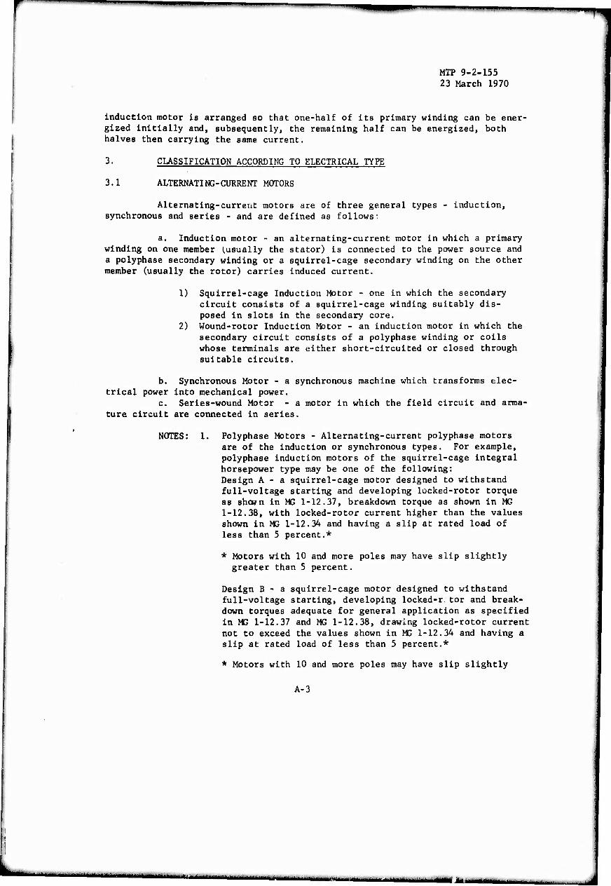
r mm
MTP 9-2-155 23 March 1970
induction motor la arranged so that one-half of its primary winding can be ener- gized initially and, subsequently, the remaining half can be energized, both halves then carrying the same current.
3. CLASSIFICATION ACCORDING TO ELECTRICAL TYPE
3.1 ALTERNATING-CURRENT MOTORS
Alternating-current motors are of three general types - induction, synchronous and series - and are defined as follows;
a. Induction motor - an alternating-current motor in which a primary winding on one member (.usually the stator) is connected to the power source and a polyphase secondary winding or a squirrel-cage secondary winding on the other member (usually the rotor) carries induced current.
1) Squirrel-cage Induction Motor - one in which the secondary circuit consists of a squirrel-cage winding suitably dis- posed in slots in the secondary core.
2) Wound-rotor Induction Motor - an induction motor in which the secondary circuit consists of a polyphase winding or coils whose terminals are either short-circuited or closed through suitable circuits.
b. Synchronous Motor - a synchronous machine which transforms elec- trical power into mechanical power.
c. Series-wound Motor - a motor in which the field circuit and arma- ture circuit are connected in series.
NOTES: 1. Polyphase Motors - Alternating-current polyphase motors are of the induction or synchronous types. For example, polyphase induction motors of the squirrel-cage integral horsepower type may be one of the following: Design A - a squirrel-cage motor designed to withstand full-voltage starting and developing locked-rotor torque as shown in MG 1-12.37, breakdown torque as shown in MG 1-12.38, with locked-rotor current higher than the values shown in MG 1-12.34 and having a slip at rated load of less than 5 percent.*
* Motors with 10 and more poles may have slip slightly greater than 5 percent.
Design B - a squirrel-cage motor designed to withstand full-voltage starting, developing locked-r tor and break- down torques adequate for general application as specified in MS 1-12.37 and MG 1-12.38, drawing locked-rotor current not to exceed the values shown in MG 1-12.34 and having a slip at rated load of less than 5 percent.*
* Motors with 10 and more poles may have slip slightly
A-3
L. """"""""""" -• "'"—— - - _^ t__

MTP 9-2-155 23 March 1970
greater than 5 per cent.
Design C - a squirrel-cage motor designed to withstand full-voltage starting, developing locked-rotor torque for special high-torque application up to the values shown in MG 1-12.37, breakdown torque up to the values shown in MG 1-12.38, with locked-rotor current not to exceed the values shown in MG 1-12.34 and having a slip at rated load of less than 5 percent. Design D - a squirrel -cage motor designed to withstand full-voltage starting, developing high locked-rotor torque as shown in MS 1-12.37, with locked-rotor current not greater than shown in MG 1-12.34 and having a slip at rated load of 5 percent or more. Single-Phase Motors - Alternating-current single-phase motors are usually induction or series motors although single-phase synchronous motors are available in the smaller ratings.
a. Examples of AC single phase fractional horsepower motors are:
Design N - a single-phase fractional-horsepower motor de- signed to withstand full-voltage starting and with a locked rotor current not to exceed the values shown in MG 1-12.32. Design 0 - a single-phase fractional-horsepower motor de- signed to withstand full-voltage starting and with a locked-rotor current not to exceed the values shown In MG 1-12.32.
b. Examples of AC single-phase integral-horsepower motors are:
Design L - a single-phase integral-horsepower motor de- signed to withstand full-voltage starting and to develop a breakdown torque as shown in MG 1-10.33 with a locked- rotor current not to exceed the values shown in MG 1-12.33. Design M - a single-phase integral-horsepower motor de- signed to withstand full-voltage starting and to develop a breakdown torque as shown in MG 1-10.33 with a locked- rotor current not to exceed the values shown in MG 1-12.33.
c. Single-phase squirrel-cage induction motors are classi- fied and defined as follows:
1) Split-phase Motor - a single-phase induction motor equipped with an auxiliary winding, displaced in mag- netic position from, and connected in parallel with, the main winding.
NOTE: Unless otherwise specified, the auxiliary circuit
A-4
■

■P»
MTP 9-2-155 23 March 1970
is assumed to be opened when the motor has attained a predetermined speed. The term "Split-phase motor" used without qualification, describes a motor to be used with- out impedance other than that offered by the motor windings themselves, other types being separately defined.
2) Resistance-start Motor - a form of split-phase motor having a resistance connected in series with the auxiliary winding. The auxiliary circuit is opened wh^n the motor has attained a predetermined speed.
3) Capacitor Motor - a single-phase induction motor with a main winding arranged for direct connection to a source of power and an auxiliary winding connect in series with a capacitor. There are three types of capacitor motors, as follows:
a) Capacitor-Start-Motor - a capacitor motor in which the capacitor phase is in the circuit only during the starting period.
b) Permanent-Split Capacitor Motor - a capacitor motor having the same value of capacitance for both starting and running conditions.
c) Two-Value Capacitor Motor - a capacitor motor using difference values of effective capacitance for the starting and running conditions.
d. Shaded-Pole Motor - a single-phase induction motor provided with an auxiliary short-circuited winding or windings displaced in magnetic position from the main winding. e. Single-phase wound-rotor induction motors are classi- fied and defined as follows:
1) Repulsion Motor - a single-phase motor which has a stator winding arranged for connection to a source of power and a rotor winding connected to a commutator. Brushes on the commutator are short-circuited and are so placed that the magnetic axis of the rotor winding is in- clined to the magnetic axis of the stator winding. This type of motor has a varying-speed characteristic.
2) Repulsion-Start Induction Motor - a single-phase motor having the same windings as a repulsion motor, but at a predetermined speed the rotor winding is short-cir- cuited or otherwise connected to give the equivalent of a squirrel-cage winding. This type of motor starts as a re- pulsion motor but operates as an induction motor with constant-speed characteristics.
3) Repulsion-Induction Motor - a form of repulsion motor which has a squirrel-cage winding in the rotor in addition to the repulsion motor winding. A motor of this
A-5
mm - __m_^—M»^—
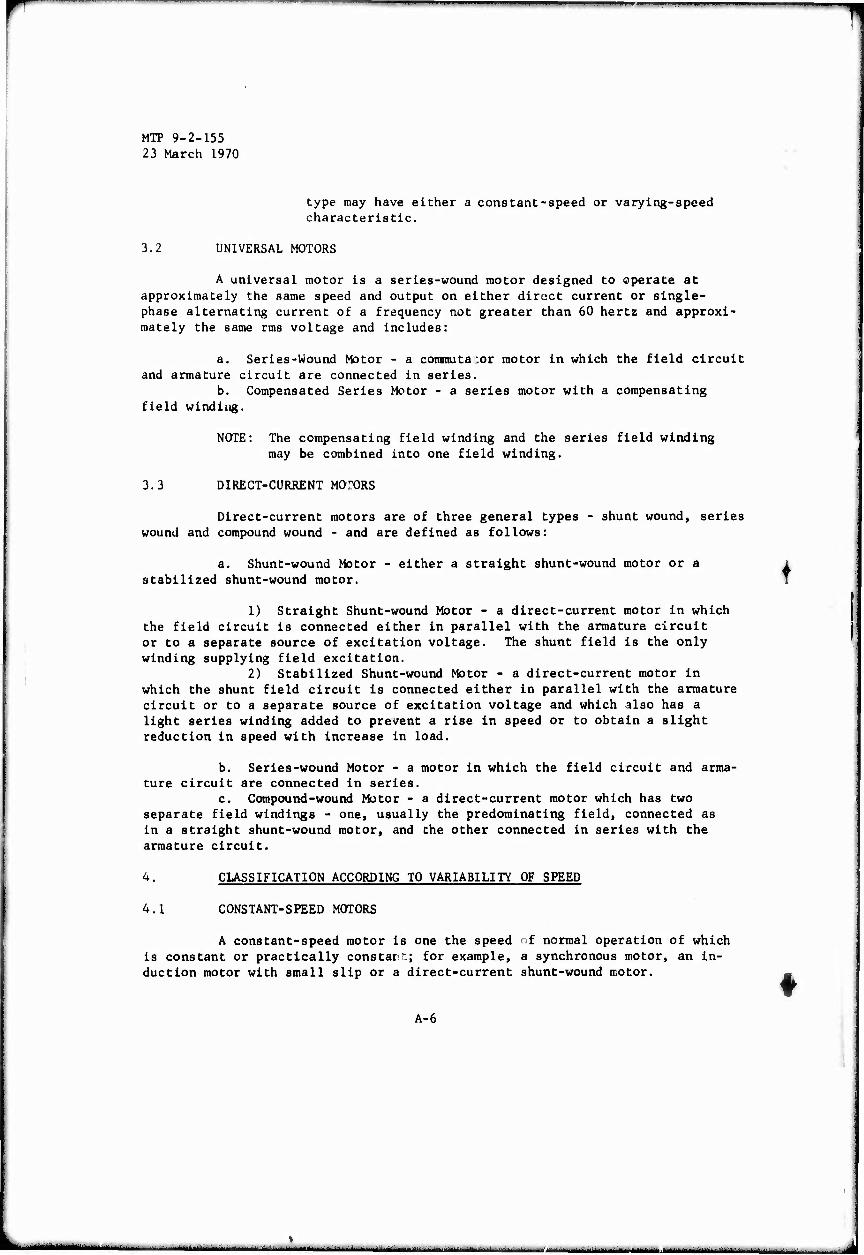
MTP 9-2-155 23 March 1970
type may have either a constant-speed or varying-speed characteristic.
3.2 UNIVERSAL MOTORS
A universal motor is a series-wound motor designed to operate at approximately the same speed and output on either direct current or single- phase alternating current of a frequency not greater than 60 hertz and approxi- mately the same rras voltage and includes:
a. Series-Wound Motor - a commuta.or motor in which the field circuit and armature circuit are connected in series.
b. Compensated Series Motor - a series motor with a compensating field winding.
NOTE: The compensating field winding and the series field winding may be combined into one field winding.
3.3 DIRECT-CURRENT MOTORS
Direct-current motors are of three general types - shunt wound, series wound and compound wound - and are defined as follows:
a. Shunt-wound Motor - either a straight shunt-wound motor or a stabilized shunt-wound motor.
1) Straight Shunt-wound Motor - a direct-current motor in which the field circuit is connected either in parallel with the armature circuit or to a separate source of excitation voltage. The shunt field is the only winding supplying field excitation.
2) Stabilized Shunt-wound Motor - a direct-current motor in which the shunt field circuit is connected either in parallel with the armature circuit or to a separate source of excitation voltage and which also has a light series winding added to prevent a rise in speed or to obtain a slight reduction in speed with increase in load.
b. Series-wound Motor - a motor in which the field circuit and arma- ture circuit are connected in series.
c. Compound-wound Motor - a direct-current motor which has two separate field windings - one, usually the predominating field, connected as in a straight shunt-wound motor, and the other connected in series with the armature circuit.
4. CLASSIFICATION ACCORDING TO VARIABILITY OF SPEED
4.1 CONSTANT-SPEED MOTORS
A constant-speed motor is one the speed of normal operation of which is constant or practically constant; for example, a synchronous motor, an in- duction motor with small slip or a direct-current shunt-wound motor.
A-6
♦
***—''''*'''*•" ■-' ■ •■■■■ - ■■■ - mm,
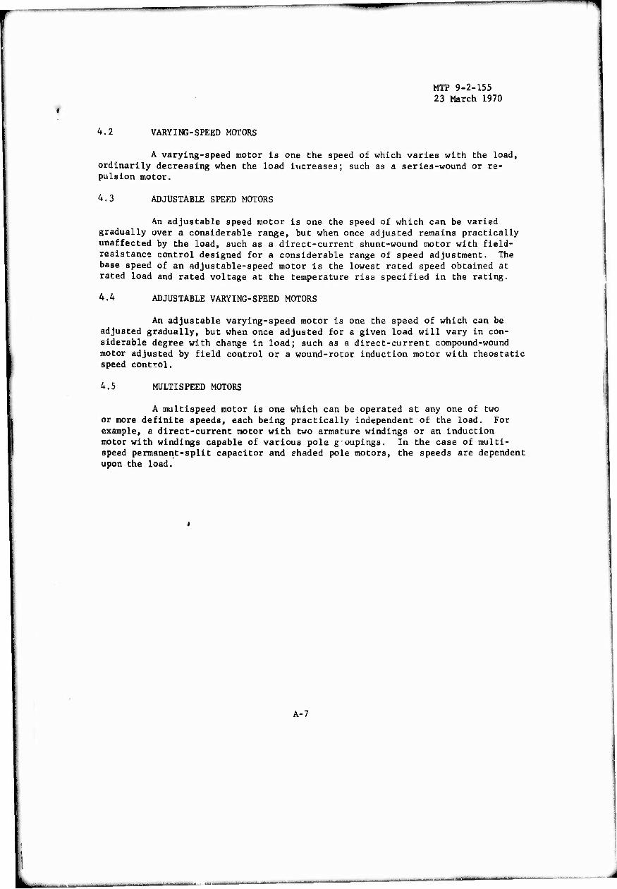
^
'
MTP 9-2-155 23 March 1970
4.2 VARYING-SPEED MOTORS
A varying-speed motor is one the speed of which varies with the load, ordinarily decreasing when the load increases; such as a series-wound or re- pulsion motor.
4.3 ADJUSTABLE SPEED MOTORS
An adjustable speed motor is one the speed of which can be varied gradually over a considerable range, but when once adjusted remains practically unaffected by the load, such as a direct-current shunt-wound motor with field- resistance control designed for a considerable range of speed adjustment. The base speed of an adjustable-speed motor is the lowest rated speed obtained at rated load and rated voltage at the temperature rise specified in the rating.
4.4 ADJUSTABLE VARYING-SPEED MOTORS
An adjustable varying-speed motor is one the speed of which can be adjusted gradually, but when once adjusted for a given load will vary in con- siderable degree with change in load; such as a direct-current compound-wound motor adjusted by field control or a wound-rotor induction motor with rheostatic speed control.
4.5 MULTISPEED MOTORS
A multispeed motor is one which can be operated at any one of two or more definite speeds, each being practically independent of the load. For example, a direct-current motor with two armature windings or an induction motor with windings capable of various pole g oupings. In the case of multi- speed permanent-split capacitor and shaded pole motors, the speeds are dependent upon the load.
A-7
MTP 9-2-155 23 March 1970
THIS PAGE INTENTIONALLY LEFT BLANK
A-8
———■i i i i
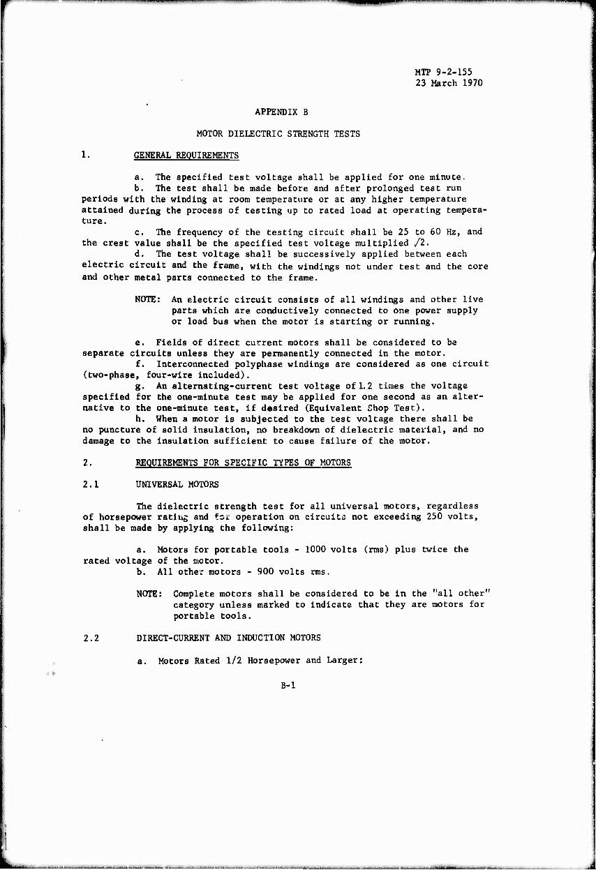
ÜH"
MTP 9-2-155 23 March 1970
APPENDIX B
MOTOR DIELECTRIC STRENGTH TESTS
1. GENERAL REQUIREMENTS
a. The specified test voltage shall be applied for one minute. b. The test shall be made before and after prolonged test run
periods with the winding at room temperature or at any higher temperature attained during the process of testing up to rated load at operating tempera- ture.
c. The frequency of the testing circuit shall be 25 to 60 Hz, and the crest value shall be the specified test voltage multiplied /2.
d. The test voltage shall be successively applied between each electric circuit and the frame, with the windings not under test and the core and other metal parts connected to the frame.
NOTE: An electric circuit consists of all windings and other live parts which are conductively connected to one power supply or load bus when the motor is starting or running.
e. Fields of direct current motors shall be considered to be separate circuits unless they are permanently connected in the motor.
f. Interconnected polyphase windings are considered as one circuit (two-phase, four-wire included).
g. An alternating-current test voltage of 1.2 times the voltage specified for the one-minute test may be applied for one second as an alter- native to the one-minute test, if desired (Equivalent Shop Test).
h. When a motor is subjected to the test voltage there shall be no puncture of solid insulation, no breakdown of dielectric material, and no damage to the insulation sufficient to cause failure of the motor.
2. REQUIREMENTS FOR SPECIFIC TYPES OF MOTORS
2.1 UNIVERSAL MOTORS
The dielectric strength test for all universal motors, regardless of horsepower rating and for operation on circuits not exceeding 250 volts, shall be made by applying the following:
a. Motors for portable tools - 1000 volts (rms) plus twice the rated voltage of the motor.
b. All other motors - 900 volts rms.
NOTE: Complete motors shall be considered to be in the "all other category unless marked to indicate that they are motors for portable tools.
2.2 DIRECT-CURRENT AND INDUCTION MOTORS
a. Motors Rated 1/2 Horsepower and Larger:
B-l
ii
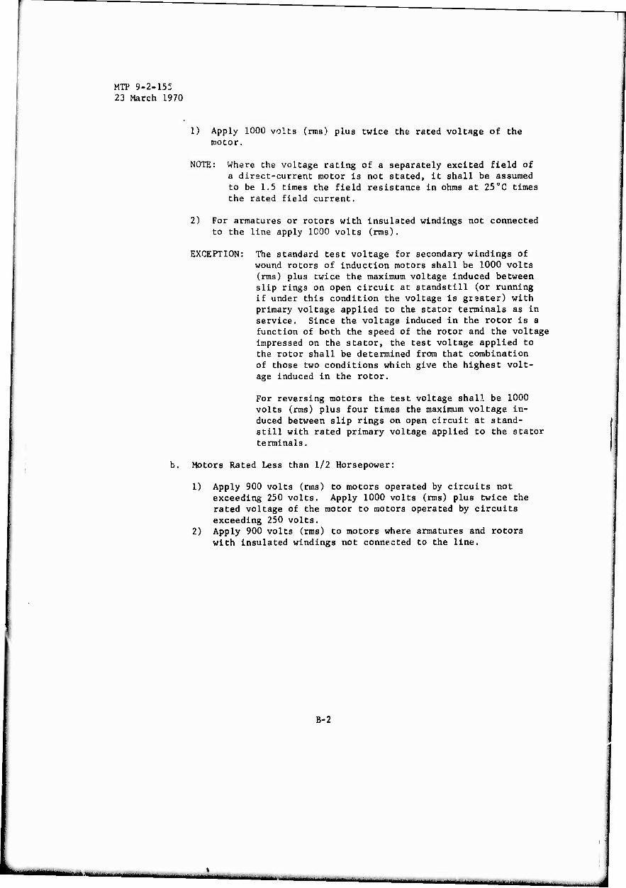
MTP 9-2-155 23 March 1970
1) Apply 1000 volts (rms) plus twice the rated voltage of the motor.
NOTE: Where the voltage rating of a separately excited field of a direct-current motor is not stated, it shall be assumed to be 1.5 times the field resistance in ohms at 25"C times the rated field current.
2) For armatures or rotors with insulated windings not connected to the line apply 1000 volts (rms).
EXCEPTION: The standard test voltage for secondary windings of wound rotors of induction motors shall be 1000 volts (rms) plus twice the maximum voltage induced between slip rings on open circuit at standstill (or running if under this condition the voltage is greater) with primary voltage applied to the stator terminals as in service. Since the voltage induced in the rotor is a function of both the speed of the rotor and the voltage impressed on the stator, the test voltage applied to the rotor shall be determined from that combination of those two conditions which give the highest volt- age induced in the rotor.
For reversing motors the test voltage shall be 1000 volts (rms) plus four times the maximum voltage in- duced between slip rings on open circuit at stand- still with rated primary voltage applied to the stator terminals.
b. Motors Rated Less than 1/2 Horsepower:
1) Apply 900 volts (rms) to motors operated by circuits not exceeding 250 volts. Apply 1000 volts (rms) plus twice the rated voltage of the motor to motors operated by circuits exceeding 250 volts. Apply 900 volts (rms) to motors where armatures and rotors with insulated windings not connected to the line.
2)
B-2
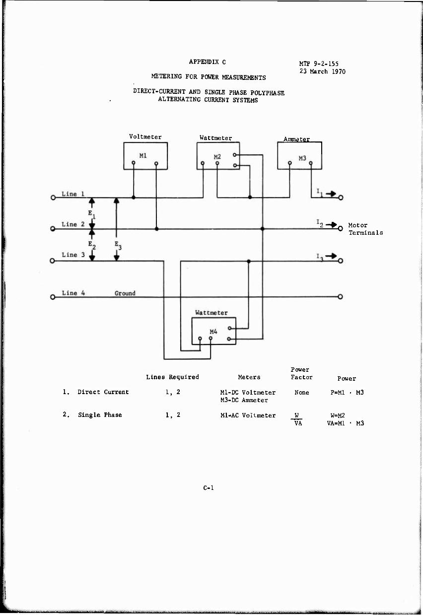
APPENDIX C
METERING FOR POWER MEASUREMENTS
DIRECT-CURRENT AND SINGLE PHASE POLYPHASE ALTERNATING CURRENT SYSTEMS
MTP 9-2-155 23 March 1970
Voltmeter Wattmeter
Lines Required
1. Direct Current 1, 2
Ammeter
2. Single Phase 1. 2
Meters
MI-DC Voltmeter M3-DC Ammeter
MI-AC VoUmeter
2—*0 Motor Terminals
Power Factor Power
None P=M1 • M3
W W=M2 VA VA=M1 • M3
C-l
■ —- -■ 1^»--' I
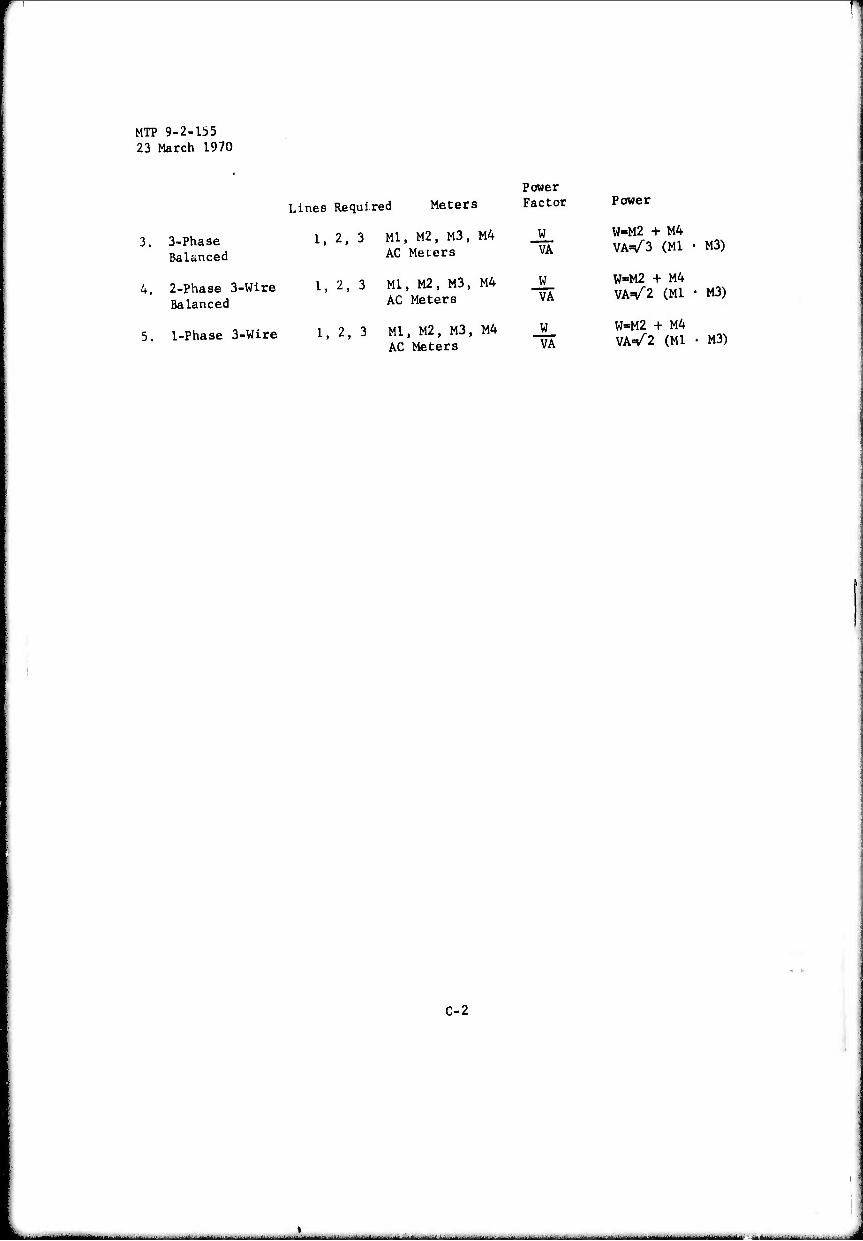
MTP 9-2-155 23 March 1970
Lines Required Meters
3. 3-Phase Balanced
4. 2-Phase 3-Wire Balanced
5. 1-Phase 3-Wire
1, 2, 3 Ml, M2, M3, M4 AC Meiers
1, 2, 3 Ml, M2, M3, M4 AC Meters
1, 2, 3 Ml, M2, M3, M4 AC Meters
Power Factor
W VA
W VA
W VA
Power
W«M2 + M4 VA=/3 (Ml • M3)
W=M2 + M4 VA=/2 (Ml • M3)
W=M2 + M4 VA=/2 (Ml • M3)
C-2
■ - --- ^-~-^-*->-.- ■...--.-..—....-^..-.^. .... .J,.-„.- .....
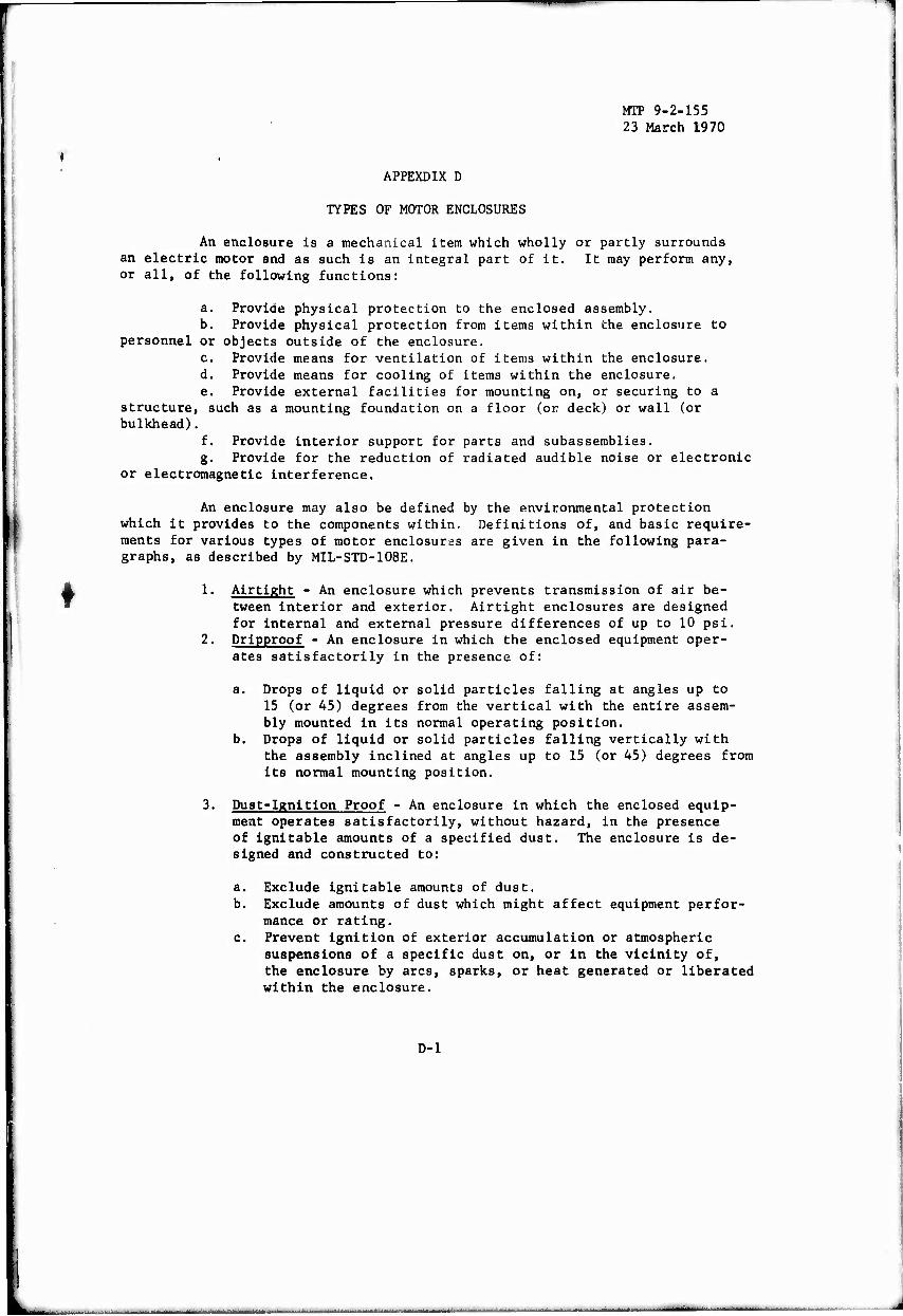
MTP 9-2-155 23 March 1970
APPEXDIX D
TYPES OF MOTOR ENCLOSURES
An enclosure is a mechanical item which wholly or partly surrounds an electric motor and as such is an integral part of it. It may perform any, or all, of the following functions:
a. Provide physical protection to the enclosed assembly. b. Provide physical protection from items within the enclosure to
personnel or objects outside of the enclosure. c. Provide means for ventilation of items within the enclosure. d. Provide means for cooling of items within the enclosure. e. Provide external facilities for mounting on, or securing to a
structure, such as a mounting foundation on a floor (or deck) or wall (or bulkhead).
f. Provide interior support for parts and subassemblies. g. Provide for the reduction of radiated audible noise or electronic
or electromagnetic interference.
An enclosure may also be defined by the environmental protection which it provides to the components within. Definitions of, and basic require- ments for various types of motor enclosures are given in the following para- graphs, as described by MIL-STD-108E.
1. Airtight - An enclosure which prevents transmission of air be- tween interior and exterior. Airtight enclosures are designed for internal and external pressure differences of up to 10 psi.
2. Dripproof - An enclosure in which the enclosed equipment oper- ates satisfactorily in the presence of:
a. Drops of liquid or solid particles falling at angles up to 15 (or 45) degrees from the vertical with the entire assem- bly mounted in its normal operating position.
b. Drops of liquid or solid particles falling vertically with the assembly inclined at angles up to 15 (or 45) degrees from its normal mounting position.
Dust-Ignition Proof - An enclosure in which the enclosed equip- ment operates satisfactorily, without hazard, in the presence of ignltable amounts of a specified dust. The enclosure is de- signed and constructed to:
a. Exclude ignitable amounts of dust. b. Exclude amounts of dust which might affect equipment perfor-
mance or rating. c. Prevent Ignition of exterior accumulation or atmospheric
suspensions of a specific dust on, or in the vicinity of, the enclosure by arcs, sparks, or heat generated or liberated within the enclosure.
D-l
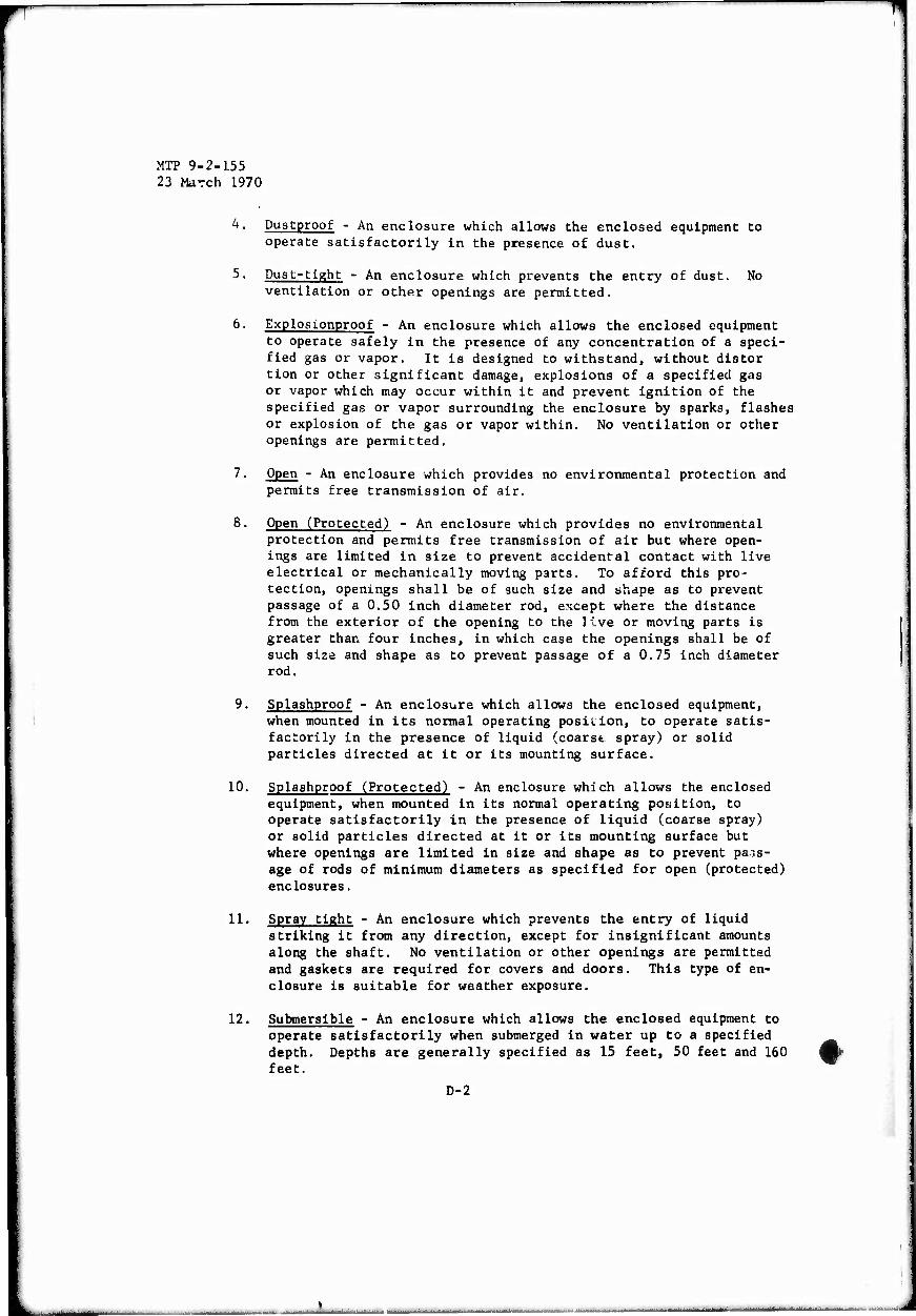
-
MTP 9-2-155 23 March 1970
4. Dustproof - An enclosure which allows the enclosed equipment to operate satisfactorily in the presence of dust.
5. Dust-tight - An enclosure which prevents the entry of dust. No ventilation or other openings are permitted.
6. Explosionproof - An enclosure which allows the enclosed equipment to operate safely in the presence of any concentration of a speci- fied gas or vapor. It is designed to withstand, without distor tion or other significant damage, explosions of a specified gas or vapor which may occur within it and prevent ignition of the specified gas or vapor surrounding the enclosure by sparks, flashes or explosion of the gas or vapor within. No ventilation or other openings are permitted.
7. Open - An enclosure which provides no environmental protection and permits free transmission of air.
8. Open (Protected) - An enclosure which provides no environmental protection and permits free transmission of air but where open- ings are limited in size to prevent accidental contact with live electrical or mechanically moving parts. To afford this pro- tection, openings shall be of such size and shape as to prevent passage of a 0,50 inch diameter rod, except where the distance from the exterior of the opening to the live or moving parts is greater than four inches, in which case the openings shall be of such size and shape as to prevent passage of a 0.75 inch diameter rod.
9. Splashproof - An enclosure which allows the enclosed equipment, when mounted in its normal operating position, to operate satis- factorily in the presence of liquid (coarst spray) or solid particles directed at it or its mounting surface.
10. Splashproof (Protected) - An enclosure which allows the enclosed equipment, when mounted in its normal operating position, to operate satisfactorily in the presence of liquid (coarse spray) or solid particles directed at it or its mounting surface but where openings are limited in size and shape as to prevent pass- age of rods of minimum diameters as specified for open (protected) enclosures.
11. Spray tight - An enclosure which prevents the entry of liquid striking it from any direction, except for insignificant amounts along the shaft. No ventilation or other openings are permitted and gaskets are required for covers and doors. This type of en- closure is suitable for weather exposure.
12. Submersible - An enclosure which allows the enclosed equipment to operate satisfactorily when submerged in water up to a specified depth. Depths are generally specified as 15 feet, 50 feet and 160 feet.
D-2
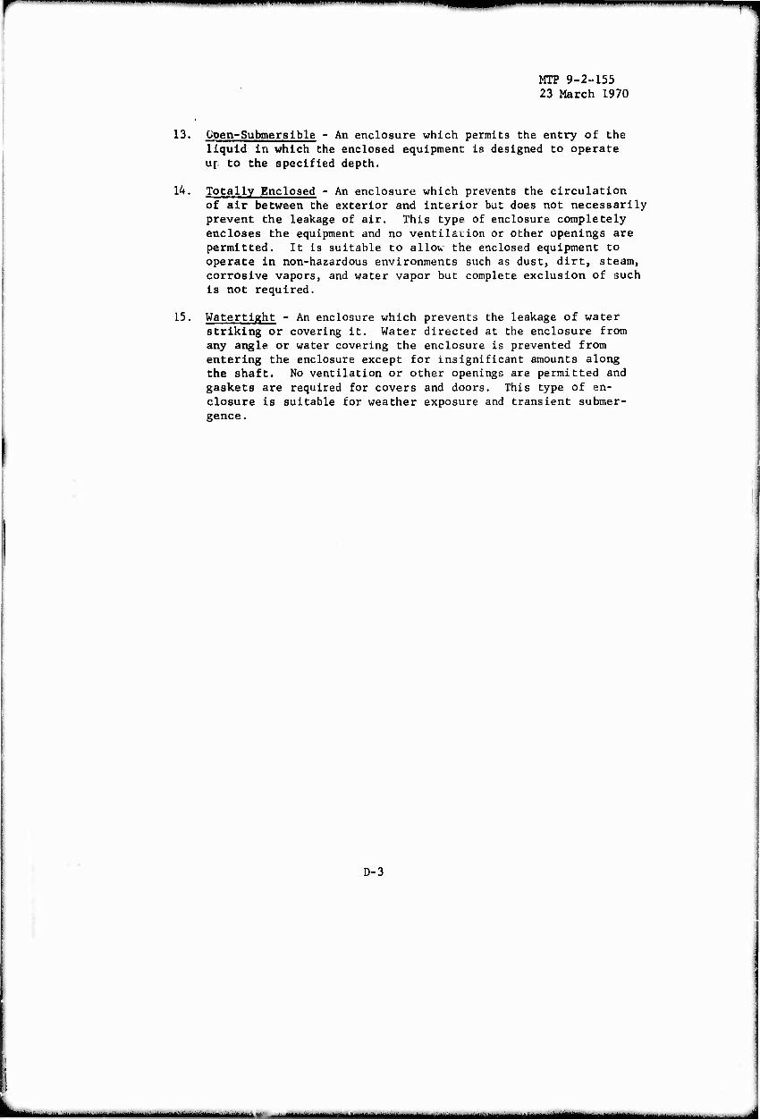
MTP 9-2-155 23 March 1970
13. Üpen-Submersible - An enclosure which permits the entry of the liquid in which the enclosed equipment is designed to operate up to the specified depth.
14. Totally Enclosed - An enclosure which prevents the circulation of air between the exterior and interior but does not necessarily prevent the leakage of air. This type of enclosure completely encloses the equipment and no ventilacion or other openings are permitted. It is suitable to allow the enclosed equipment to operate in non-hazardous environments such as dust, dirt, steam, corrosive vapors, and water vapor but complete exclusion of such is not required.
15. Watertight - An enclosure which prevents the leakage of water striking or covering it. Water directed at the enclosure from any angle or water covering the enclosure is prevented from entering the enclosure except for insignificant amounts along the shaft. No ventilation or other openings are permitted and gaskets are required for covers and doors. This type of en- closure is suitable for weather exposure and transient submer- gence.
D-3
- ■- -■■- • ■■ n
■ 1—rm
MIT 9-2-155 23 March 1970
THIS PAGE INTENTIONALLY LEFT BLANK
D-4
MT? 9-2-155 23 March 1970
APPENDIX E
METHODS OF DETERMINING MOTOR TEMPERATURE RISE
1. INTRODUCTION
An Important characteristic of motors is the temperature that its components reach after operation over a period of time. The temperature rise of the motor is the difference between the total temperature of the various components (after stability has been achieved) and the ambient temperature of the surroundings. Measurements are taken at specified periods during the run showing temperatures of such parts as the frame, field coils, bearings, etc.
Determinations of the temperature rise are made under full load conditions, where the load is applied, as required by the item being tested. Any practicable method of loading the motor may be used. Temperature rise measurements shall be made in accordance with the latest revisions of the following IEEE publications, as applicable.
112A IEEE Test Procedure for Polyphase Induction Motors and
113 IEEE Test Procedure for Single Phase Induction Motors. 114 IEEE Test Code for Direct-Current Machines. 115 IEEE Test Procedure for Synchronous Machines.
In general, three methods for determining the temperature rise of motor components can be used depending again on the physical characteristics of the motor Involved. These methods are:
a. Thermometer method b. Embedded detector method c. Resistance method
The allowable temperature rise for various components Is determined by the class of Insulation involved (see Appendix G) and must be In accordance with specifications set forth by NEMA MG-1, for the method of measurement utilized.
2. TEMPERATURE RISE BY THERMOMETER
Temperature rise can be determined by thermometers or thermocouples placed on the machine at selected positions on the windings, frame, etc. with the bulb or junction suitably protected. The highest reading sensor on a given component during operation and shut-down is taken as the temperature of that part.
Thermocouples are generally used to measure surface temperatures of the windings and core, as well as other motor parts. They may be used for embedded-detector measurements (see paragraph 4) but the expense Involved in installing them and apace requirements often precludes their use in this type
E-l
a. No. Generators.
b. No. c. No. d. No.
I
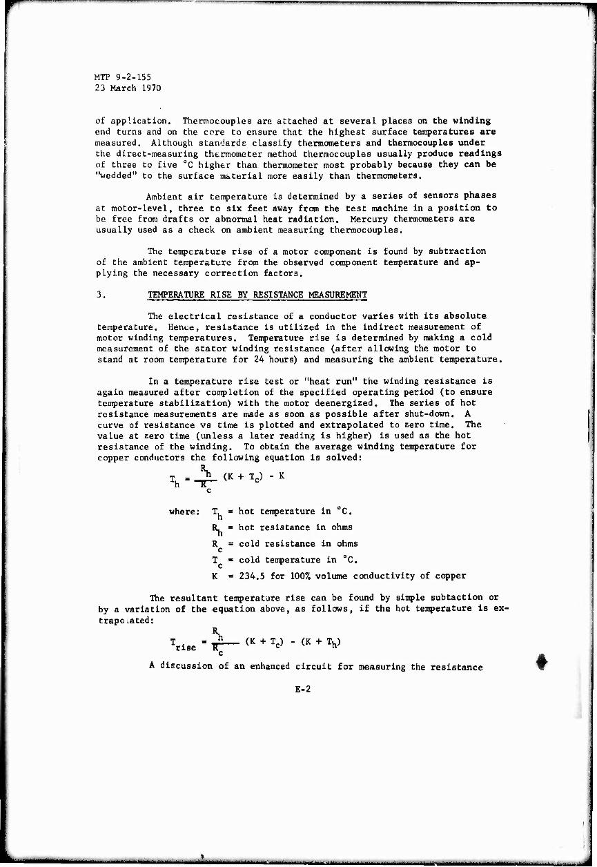
■wnmpwwwilf
MTP 9-2-155 23 March 1970
of application. Thermocouples are attached at several places on the winding end turns and on the core to ensure that the highest surface temperatures are measured. Although standards classify thermometers and thermocouples under the direct-measuring thtrmometer method thermocouples usually produce readings of three to five 0C higher than thermometer most probably because they can be "wedded" to the surface material more easily than thermometers.
Ambient air temperature is determined by a series of sensors phases at motor-level, three to six feet away from the test machine in a position to be free from drafts or abnormal heat radiation. Mercury thermometers are usually used as a check on ambient measuring thermocouples.
The temperature rise of a motor component is found by subtraction of the ambient temperature from the observed component temperature and ap- plying the necessary correction factors.
3. TEMPERATURE RISE BY RESISTANCE MEASUREMENT
The electrical resistance of a conductor varies with its absolute temperature. Hence, resistance is utilized in the indirect measurement of motor winding temperatures. Temperature rise is determined by making a cold measurement of the stator winding resistance (after allowing the motor to stand at room temperature for 24 hours) and measuring the ambient temperature.
In a temperature rise test or "heat run" the winding resistance is again measured after completion of the specified operating period (to ensure temperature stabilization) with the motor deenergized. The series of hot resistance measurements are made as soon as possible after shut-down. A curve of resistance vs time is plotted and extrapolated to zero time. The value at zero time (unless a later reading is higher) is used as the hot resistance of the winding. To obtain the average winding temperature for copper conductors the following equation is solved:
T = y (K + Tc) h ^ c
c
where: T. = hot temperature in 0C.
R. = hot resistance in ohms
R = cold resistance in ohms c
T = cold temperature in "C.
K = 234.5 for 100% volume conductivity of copper
The resultant temperature rise can be found by simple subtaction or by a variation of the equation above, as follows, if the hot temperature is ex- trapo ated:
Trise = ^— (K + Tc) - (K + Th) c
A discussion of an enhanced circuit for measuring the resistance
E-2
'm"lfc^'^"'^ '"—"""■' ■'■ ■"' '- •"• ■ "■- ■ ■ — — - - • --

MTP 9-2-155 23 March 1970
(and hence the temperature rise) of A-C windings, while they are energizeJ'is presented an Appandix F.
4. TEMPERATURE RISE BY EMBEDDED DETECTOR
On large motors it is common practice to supply the machines with with temperature sensors embedded in the windings. The temperature of the wind- ing is then determined by the detector when it is connected to a suitable measuring instrument. Commonly used embedded detectors include, thermocouples and thermistors. Many modern motors which feature special windings utilize such devices as the sensing element in the thermal protection system of the motor in conjunction with thermal overload relays etc.
While the readings are a form of "thermometer" measurement their values are more closely related to those obtained from resistance-type measurements.
E-3
■--- ■ ■

MTP 9-2-155 23 March 1970
THIS PAGE INTENTIONALLY LEFT BLANK
E-4
._ —, . —i
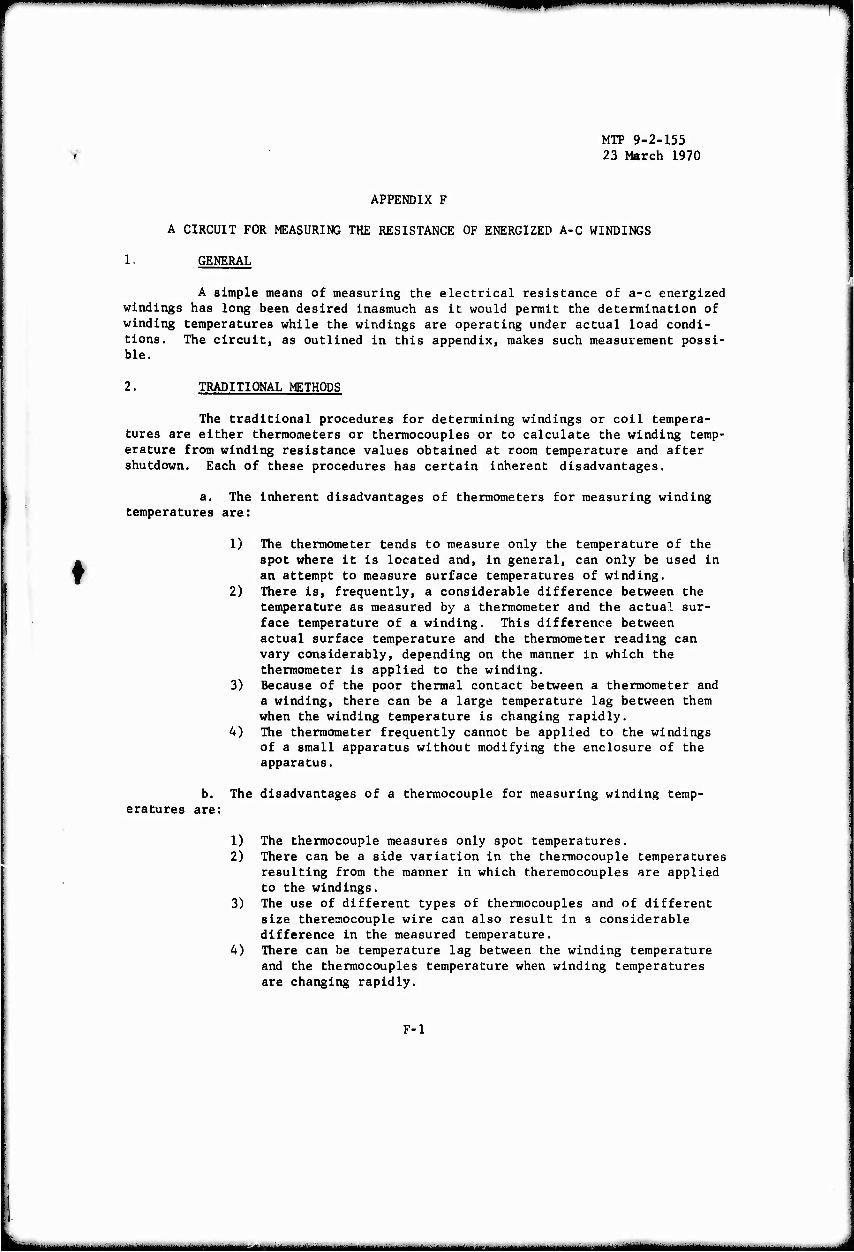
MH^
MTP 9-2-155 23 March 1970
APPENDIX F
A CIRCUIT FOR MEASURING THE RESISTANCE OF ENERGIZED A-C WINDINGS
1. GENERAL
A simple means of measuring the electrical resistance of a-c energized windings has long been desired inasmuch as it would permit the determination of winding temperatures while the windings are operating under actual load condi- tions. The circuit, as outlined in this appendix, makes such measurement possi- ble.
2. TRADITIONAL METHODS
The traditional procedures for determining windings or coil tempera- tures are either thermometers or thermocouples or to calculate the winding temp- erature from winding resistance values obtained at room temperature and after shutdown. Each of these procedures has certain inherent disadvantages.
a. The inherent disadvantages of thermometers for measuring winding temperatures are:
1) The thermometer tends to measure only the temperature of the spot where it is located and, in general, can only be used in an attempt to measure surface temperatures of winding.
2) There is, frequently, a considerable difference between the temperature as measured by a thermometer and the actual sur- face temperature of a winding. This difference between actual surface temperature and the thermometer reading can vary considerably, depending on the manner in which the thermometer is applied to the winding.
3) Because of the poor thermal contact between a thermometer and a winding, there can be a large temperature lag between them when the winding temperature is changing rapidly.
4) The thermometer frequently cannot be applied to the windings of a small apparatus without modifying the enclosure of the apparatus.
b. The disadvantages of a thermocouple for measuring winding temp- eratures are:
1) The thermocouple measures only spot temperatures. 2) There can be a side variation in the thermocouple temperatures
resulting from the manner in which f.heremocouples are applied to the windings.
3) The use of different types of thermocouples and of different size theremocouple wire can also result in a considerable difference in the measured temperature.
4) There can be temperature lag between the winding temperature and the thermocouples temperature when winding temperatures are changing rapidly.
F-l
i
"•*-—■ ~*~*^^~~~~-*~***-~**~*~~***~~~*-^ ■.-.J.,~~-,—, ^—^—m
MTP 9-2-155 23 March 1970
5) It is frequently necessary to disassemble the apparatus under test to install thermocouples.
6) With hermetically sealed apparatus, it is necessary to build special test units to bring out the thermocouples
c. The method of determining winding temperatue by measuring winding resistance after shutdown also has the following inherent disadvantages:
1) Accurate winding resistance measurements cannot be made be- cause of the changing resistance.
2) Since resistance readings cannot be made immediately after shutdown, it is general practice to obtain a number of re- sistance readings after various time intervals and to plot these values back to zero time on logarithmic graph paper. This procedure is time-consuming and somewhat inaccurate since the cooling curve is not entirely logarithmic.
3) Wirding temperatures cannot be followed under changing load conditions by this method.
4) Equipment such as refrigeration equipment cannot be frequently shut down during tests without disrupting the entire test.
3. EVOLUTION OF NEW METHOD
It will be realized that, if attempts were made to measure the re- sistance of an a-c energized apparatus using a Wheatstone bridge or an ohmmeter, the alternating current voltage would damage or burn out the bridge or ohmmeter. Even if it were possible to connect the bridge directly to an a-c energized apparatus it still would be impossible to measure the resistance of this ap- paratus since its resistance would be paralleled by the resistance of all of the other loads on the line and, also, by the resistance of the secondary wind- ing of the line transformer. It was, therefore, necessary to devise a circuit which would circumvent these two basic obstacles.
The circuit in Figure F-l illustrates the manner in which this was accomplished. First, the voltage problem was surmounted by the use of a sub- stantially equal and opposite bucking voltage as supplied by a potential trans- former. This allows a bridge or ohmmeter to be connected to one terminal of the apparatus on test and to one side of the secondary of the transformer since there is substantially zero voltage between these points. It was originally thought necessary to use a variable transformer to buck the voltage to zero, but it was found unnecessary since a few volts of alternating current would not adversely affect a bridge.
The necessary isolation of the windings under test so that the di- rect current from the bridge or ohmmeter will not flow through the other par- alleling resistance in the circuit is accomplished by the use of the capacitor bank in the circuit of Figure F-l. It will be noted that the primary winding of the bucking transformer is also on the line side of the capacitor bank. As such, this permits the bridge to measure the sum of the resistance of the wind- ing in question, the secondary of the transformer, and the leads. The actual winding resistance is then obtained by subtracting the resistance of the
1-2
——Ml—Mlll»Mli.l IHMIIIM—M --- - ■- -■ ■'■
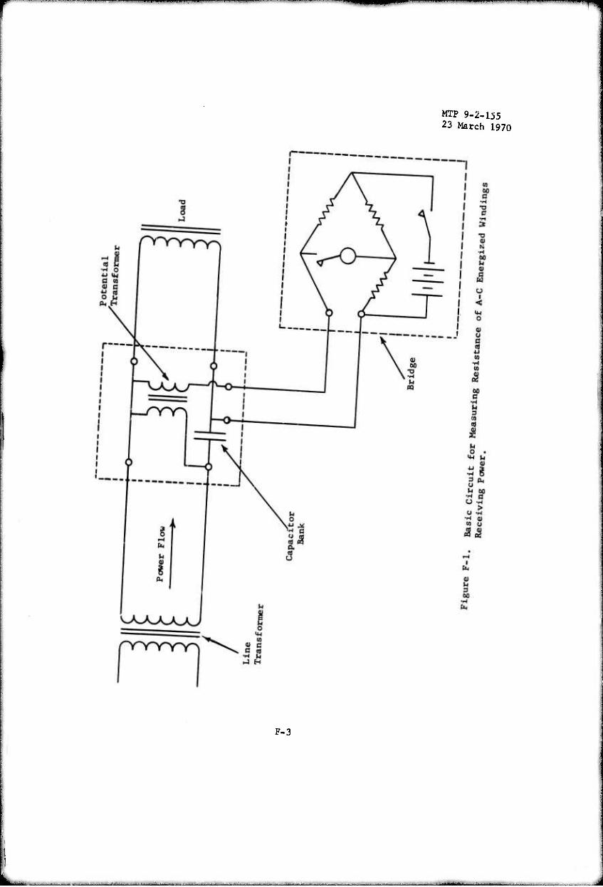
MTP 9-2-155 23 March 1970
F-3
MTP 9-2-155 23 March 1970
transformer and leads from the total resistance as obtained from the bridge. The winding temperature, of course, can then be obtained by using the equation:
Th = (Rh/Rc) (K + Tc) - K
where:
Rh = hot winding resistance Re = cold winding resistance at the start of test Tc = cold winding temperature as obtained from thermometer at start
of test K = constant for 1007» volume conductivity of the winding metal
For temperatures in degrees centigrades, this constant is 234.5 for copper windings and 221 for aluminum windings. For temperatures in degrees Fahrenheit, it is equal to 39Ü.1 for copper and the 365.8 for aluminum. Figure F-2 illustrates how this circuit can be used in reverse to measure the resistance of a-c energized windings which supply a-c power such as alternator windings or a transformer secondary winding.
Whereas, the circuit shown in Figures F-l and F-2 illustrated the fundamentals of this circuits operation, it will be realized that further cir- cuit refinements were necessary for successful use in a test department. The circuit shown in Figure F-3 incorporates refinements such that It can be suc- cessfully used to measure the winding resistance of either single-phase or poly- phase equipment. To measure the resistance of energized polyphase equipment, it is necessary to insert another capacitor bank in the third line so that the direct current of the bridge cannot flow back through the line transformer. With grounded neutral polyphase equipment, it is necessary to go a step further and to have a capacitor bank in all three supply lines to isolate the flow of bridge current. When used with wye-connected polyphase equipment, the rasist- ance of 2-phase windings In series is measured. With delta-connected equipment, the resistance of a phase winding paralleled by the other 2-phase winding in series is measured.
It will be noted that a 4-pole double-throw switch has been incorporated into the circuit, as shown in Figure F-3. This switch has a number of purposes. First, it serves to connect the potential transformer into the circuit when the iwitch is thrown to its READ or ON position. This is desirable so that the poten- tial transformer is only energized when it is necessary to take a resistance reading. In this manner, there is very little heating of the transformer which would change the resistance of the transformer secondary winding. It should again be noted that the purpose of the potential transformer is only to supply a bucking voltage and not to supply power. As such, the temperature rise would normally be small even if it were energized continuously. In the OFF or CHECK position, as shown, this switch shunts the capacitor banks Cl and C3 and connects the secondary of the potential transformer directly to the bridge terminals. Normally, the impedances of the capacitor banks are such that there is a few volt drop across them at the full-load capacity of these circuits. It is de- sirable to shunt the capacitor banks Cl and C3 so that there will be no voltage drop across them when the circuit is OFF. This allows voltmeters and wattmeters
F-4
"•""^ *"* llll —-.- ^ llt-Mi^^M
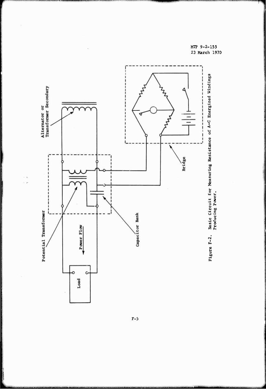
—I—I T^T-WP^^«
MTP 9-2-155 23 March 1970
CO 00 C
•H X) 0
•i-l 3 -a (U N •H M
<U c w u
I <
0) u
(0 •l-l CO
I
M o •
a) ä i 3 PH u
•H e u
U 3
w 5
CM i
60
F-5
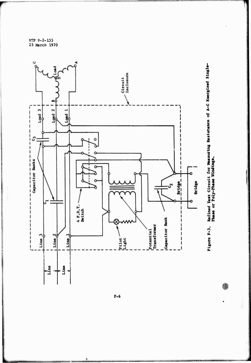
fl
MTP 9-2-155 23 March 1970
I
60 U
% H O
1
«
I 3
u o 1 US 2.2 S1? «^ ■ o A* XI o
Is mi
s
I
F-6
■ ■■ I ■■■"""""^^■'■■■■■■■■■,^"'^
»
MTP 9-2-155 23 March 1970
to be connected on the line side of the circuit so that their readings will be correct when the circuit is in the OFF or CHECK position. These meters can be connected to the load if provisions are made to disconnect them while a re- sistance reading is being made. Connecting the secondary of the transformer to the bridge terminals on the CHECK or OFF position permits its secondary resistance to be checked periodically for any slight change of the tare re- sistance. It will be noted that two blades of the switch to the secondary of the transformer are connected in parallel. This was found to be desirable to obtain a low and stable resistance through the switch.
The circuit, as shown in Figure F-3, is intended to be used to make periodic resistance readings during a heat run, but it also can be used to make continuous readings should they be desired. To do this, it is necessary that a circuit be energized for a few hours at the desired test voltage with the switch in the READ position and with no load being applied to the load terminals. This permits the potential transformer to heat and allows its tare resistance to be- come stabilized, as can be determined by occasionally switching to the CHECK position.
Another refinement of the circuit in Figure F-3 is the addition of a capacitor bank C2 directly across the bridge terminals of the circuit. The use of this additional capacitor bank was found to be desirable to minimize the effect of line surges on the galvanometer of the bridge. Without this addi- tional capacitor bank, it occasionally was found that the switching surges on the line or a pulsating motor load would cause the galvanometer to be unstable. To minimize galvanometer unstabllity caused by these surges, it has also been found desirable to operate this circuit from a "stiff" line or, better yet, to operate from a separate voltage regulating transformer or separate alternator, if available. The addition of a pilot light to the circuit is desirable so that the circuit will not be energized any longer than necessary. In this manner, heating of the transformer is very slight and, hence, the change in the transformer resistance is negligible.
In the original circuits which were built in 1953, standard 1-and 1^-kva power transformers were used because they were readily available. They were connected for 230/230-volt operation, and as such the circuits could be used for voltages up to about 250 volts. Transformers of this size were em- ployed so that the tare resistance of their secondary winding (about 0.3 ohm) would not be greater than the resistance of the induction motor windings to be measured. It was found desirable to limit the use of these test circuits to an apparatus having a resistance greater than the tare resistance to obtain sufficiently accurate resistance reading. It was soon realized that, if a special potential transformer having a much heavier secondary winding than the primary winding were used, considerable saving in weight could be realized. Consequently, special potential transformers were designed and are presently used in existing circuits. The original circuit also used banks of standard 110-volt a-c electrolytic motor-starting capacitors, rated 850 to 900 micro- farads, since they were readily available. Here again, it was realized that these capacitors were many times larger than needed, since even under full loads the voltage across them was only 4 or 5 volts. Subsequently, electro- lytic capacitors rated 15 volts a-c and having a capacity of 4,000 to 9,000
F-7
MTP 9-2-155 23 March 1970
microfarads were obtained. As such, it has been possible to reduce the size of the capacitor banks by a ratio of about 10 to 1. At this point it should be mentioned that the internal leakage resistance of these capacitors, in ef- fect, parallels the resistance being measured, and establishes the maximum resistance which can be measured with sufficient accuracy. It is for this reason that a maximum resistance rating is applied to a given circuit.
Although, the measuring circuit was originally developed to deter- mine the temperature of motor windings by the resistance method, it also has been used to determine the winding temperature of alternators and trans- former windings. Figure F-4 shows the heating and cooling curves of the primary and secondary windings of a l»kva tvansformer, as obtained by using measuring circuits in both the primary and secondary windings. In this test, the transformer was first loaded to full and then reduced to 50 percent load after 5^ hours. Figure F-5 shows a temperature rise curve of the winding of a 1.5-'.sva 3-phase 115-volt 430-cycle motoi alternator which was first loaded to a full load and then to 50 percent load.
Figure F-6 illustrates a very important use for this measuring cir- cuit. Shown here are curves of winding temperature and power of a 1/6-horse- power hermetic refrigerator motor, as obtained when the refrigeration system reduced the refrigerator cabinet from room temperature of approximately 40 de- grees centigrade to its normal operating temperatures. It will be noted that, under such a test, the power and winding temperature reach a peak and then fall off as the cabinet temperature is pulled down. Without the use of this resistance-measuring circuit it would be difficult or impossible to determine accurately the peak winding temperatures.
JL
F-8
1
kaMMMMMM — J
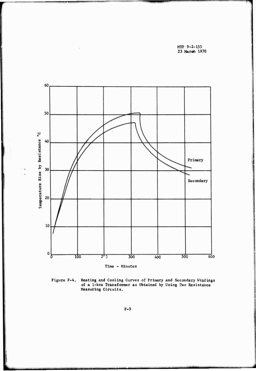
T^
MTP 9-2-155 23 Maroh 1970
!
100 2^0 300
Time - Minutes
400 500 600
Figure F-4. Heating and Cooling Curves of Primary and Secondary Windings of a 1-kva Transformer as Obtained by Using Two Resistance Measuring Circuits.
F-9

MTP 9-2-155 23 March 1970
o
1 -i
y
o -1
r>
1 o
^
o
äS O HJ > i I-I
m .-i r^ 3 r^ fe
0) o (0 4J
.S-o PH <U
1 "D «n g « j > X 4J
1 CO m u
• -H ^1 fe
(I) w (d
«y ^ o
en A 0,' co u w OO-H 1 Ig •M •o s a M •
•rl O -O • ^ «8 § •se^ •H 0) 4J H <u « d
ß^ö fl 1 U M) h
(3 a) 0) -H »!< M +J 1 d s o et! 9 in
o ai s o U 4J d <u 4J ^ ß nt u a) U ^J3 <U « +J
BO -O 3 n ß H st (S
• |
fe a ^ 60 •H U
o O
0 aDUB3STsau Xq as-pH aan^saadurax
F-10
MM

MTP 9-2-155 23 March 1^70
o o o
■Jr:^S
§ vo tn if
F-ll
o o
U •i-l U
(U X u
CO
o o o o « m
to T3
«4-1 o
■u 3
o o o a M
(U CM •M
B g H
'S 0)
o o o i-(
<u u 3
<u
14-1 «J o u to M)
M <4-l
(U
o ä
vO I
fa <u u 9 00 •H fa
^ —.
r^immm^m^^^^^^^^^^^^m^^^^^—^—^mmm^
MTP 9-2-155 23 March 1970
THIS PAGE INTENTIONALLY LEFT BLANK
F-12
MTP 9-2-155 23 March 1970
APPENDIX G
INSULATION SYSTEMS AND TEMPERATURE RISE
1. INTRODUCTION
The operating of an electric motor has an adverse effect on the life of the motor winding. Long insulation life and higher-than-rated operating temperature are incompatible.
The heart of a motor is the winding, which must be electrically in- sulated from adjacent parts. An insulation "system" is an assembly of insulat- ing materials in association with the conductors and supporting structural parts of the motor. Basically, the insulation system consists of a coating of enamel, or enamel and yarn composition applied to the wire conductors. The coils of conductors may be wrapped in insulating tape. The coils are placed in motor-core "slots" which are lined with an insulating "tube" when random windings are used.
Adjacent coils and phases of the winding are separated, both in the slot and in the end turns which project from the core. After connections are insulated and tied the entire winding is impregnated with an insulating varnish which also serves as a binder and affords moisture and mechanical protection to the system. Extra varnish coatings or encapsulations provide additional pro- tection.
Component parts of a motor are subject to thermal degradation, or aging which results in a gradual loss of winding insulation. In time, dielec- tric stresses on the thermally weakened insulai .on cause a breakdown between the conductors, or to ground. Terminal damage usually results and the winding life is ended.
2. INSULATION CLASS
The specific life which a particular insulation will have at a given temperature is defined, functionally, by its ability to endure moisture, vibration, voltage and thermal aging. In a system designed to melt current standards, motor winding life is approximately 35,000 hours when operated at rated temperature and subjected to normal humidity and dielectric and mechanical stresses.
NEMA specifically defines the following insulation classes: A, B, F, and H. These classes correspond to the insulating material classes set forth by the IEEE as 105, 130, 155, and 180 respectively in its Publication No. 1, General Principles Upon Which Temperature Limits Are Based in the Rating of Electrical Equipment. The temperature limitations for the various insulation classes and the materials commonly used in the various classes are listed in
Table G-I.
G-l
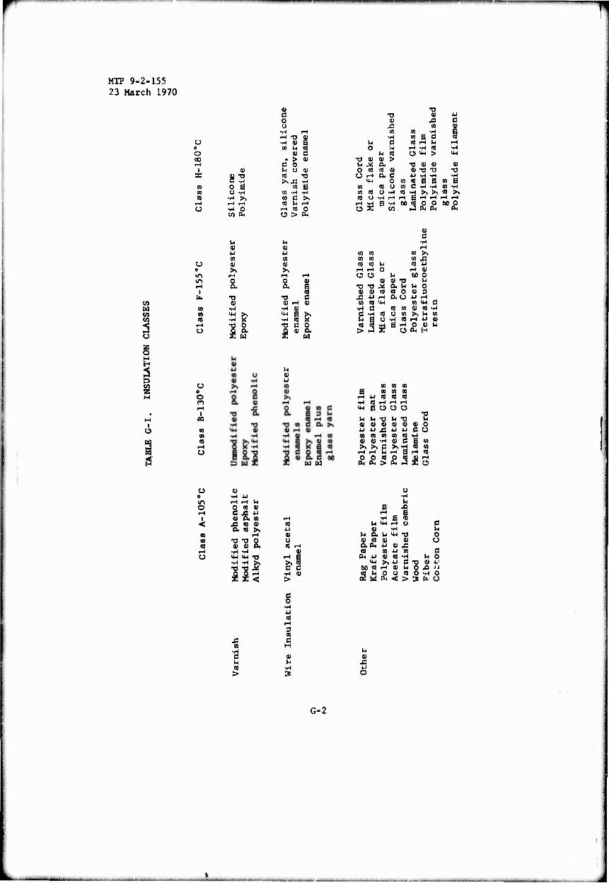
MTP 9-2-155 23 March 1970
u o O 00 r-t
I ac
CO
U
w to
§
o o m m r-t
I tM
(0 cn CO
i-H o
o PI l-H I «
CO CO CO
«I
O B O -M
■H O
1-. (U u tn
>. o a -a ai
1 & o a. w
0 o
•H ^H ^ TJ 1 •H 01 ca u CO
01 c « > IU
d o U 0 D CO T5 >, J: •.-1
cn B cn -H ■H cn C >. co u rH i-i co 0 Ü > PL,
u 4) 4-J cn 0) >-.
r-l r-l o 0) a §
■o 0 0) rH (U
•i-l 0) M-l B .H (0 g1 -a e o fi 0)
01
(!) J2 cn •^
wi d o u
U (0 •O 0) 0) > U M Ct. O CO CO 0) U i-H Q. C
0)
ca
(0 S d «8 rH W rH .rl CO Ü >« >
-o 0) a) 01 tJ "O U -iH -H
0) XI
3 53
0 cn eg g B ca a « u ca d -ri -I-I ca MH Ü •iH CO -rj >, >, CO >» .H l-H rH B i-H i-H ^ rH B •iH
CO 60 CO O O
J PLI Ol MO
cn cn to >> ca ca to J2 to co IH tO U
i-H i-H 0 ^1 V W O U t» 0
01 0) T3 M •ü T3 X a M M o V 0) CO CO O 01 3
J3 « rH aU 4J rH ca co UH 10 M-l a
■H Ö CO co V CO •iH C -rl CO O to >, M cn u 1 0 •H tO IH 4J 01 CO 9 SI ß rH O tU u > J O PH H
MH
cn cn to ca ca ca
u co to co «J rH rH i-H B O Ü O
(H "O
W W
iH u "O 01 0) <u 4J 4J J3 CO to to 0) IU •I-I ►. >. B rH i-H o 0 to a. d, >
•g 4J d CJ
to CO tu d B 'o >, •H to cn
rH B rH 10
ITl i-H rH U O 0 « Ol l-H d J3 4J
1 01 a CO rH < X) CO 0) to
a CO ►» 4J CO rH 01 1» T3 •o 0 u CO 0) a> a tS i-H
i-H •rl •H 3J o MH 14H •a d d
•iH •rl ^ i-H •H 0) >
g •iH U to
rH
01 £ d 91 M •H d 01 u IH CO •rl > »
B
u •H
J3
•H B to iH Ü •^
01 01 01 £
ca 4J ca 0) to •i-l
MH >, u d 60 to rH 0) SH « M o u ca (2 üd d < >
u
u a. oi co an« «
d o o d
h o •O 0) J-1
O Ä JJ O •i-l o S fc O
G-2
JIMM^JUJ.^-..^ ■^ndiiBdi inhanilriii
t MTP 9-2-155 23 March 1970
A material listed for one class may be used in a lower temperature class. An important "rule-of-the-thumb" for motor insulation is that for every 10 C reduction in winding temperature the life of the winding is approximately doubled.
Effects of temperature on winding insulation are decreased if materials that retain their insulating properties at high temperatures are used. Hence, a Class B system will last approximately four times as long as a Class A system when each is operated at the same temperature. Also, when each is operated at its rated temperature, they will have equal lives. The same comparisons can be made with Class B and Class F systems, etc.
3. MOTOR TEMPERATURES
An electric motor in operation has a higher-than-ambient temperature that is a combination of the temperatures of its various parts. As an electric motor converts electrical energy into mechanical energy losses are incurred which are converted into heat which produces the temperature rise of the wind- ing and other components. Motor temperatures can be used as an index of the rate at which the insulation is aging. Since the insulation surrounds the winding, the winding temperature is most important. Because the winding is placed in slots in the motor core, the core temperature is of secondary impor- tance to the winding temperature.
When a major winding fails because of temperature aging, the hottest part of the winding will fail first. This point is called the "hot spot" and is usually on the axial center line of the core in one of the slots. Unless a winding is equipped with an embedded detector in the center of the hot spot, it is necessary to measure the winding temperature at an accessible point on the end turns (see Appendix E). This measured temperature forms the basis for the defined temperature rating. Hence, to get the true temperature of the hot spot, a hot spot allowance must be added to the measured temperature.
Various motor enclosures cause a difference in hot spot allowance. A totally enclosed non-ventilated motor (TENV) with the most uniform winding temperature, will have the highest hot spot temperature while a totally en- closed fan-cooled motor (TEFC) with the cooling air passing directly over the winding end turns, will have the lowest hot spot temperature
Winding and core temperatures are measured during a "heat-run" and the ambient temperature measured during the heat run is subtracted to give the winding or motor temperature rise. All motors are rated by temperature rise in a standard ambient of 40<,C (104oF) which will seldom be exceeded during application. For special arabients in excess of 40oC, a standard motor can be used at reduced load or reduced life, or with a higher insulation class or a special low-rise motor can be used. The converse of these tech^qucj may be applied for special ambients well-below 40oC.
Standard motor temperatures ratings in terms of winding temperature rise have been established by NEMA, The bases for these ratings are:
G-3

MTP 9-2-155 23 March 1970
a. The temperature limits assigned to Classes A, B, F, and H insu- lations.
b. The standard 4G0F ambient temperature allowance is subtracted from these limits.
c. The hot spot allownace is deducted also and the remainder is the temperature rise.
NOTE: For general purpose dripproof A-C motors, with Class A Insu- lation, an additional 10oC allowance it usually deducted for a service factor. This permits the motor to be operated above its rated horsepower, in standard ambient and at standard life, or in ambients up to 10°C above standard at rated horsepower.
Table G-Il shows A-C motor temperature limits as adapted from NEMA MG-1-12-41 and 12-42 as an example (single phase and polyphase induction motors)
G-4
^MHUMM«

MTP 9-2-155 23 March 1970
TABLE G-II. A-C MOTOR TEMPERATURE LIMITS
TEMPERATURE
Class A Class B Class F Class H
t
1.0 SERVICE FACTOR - DRIPPROOF
Ambient Temperature Rise (thermometer) Rise (resistance) Service-Factor Margin Hot Spot Allowance
TOTAL TEMPERATURE
- TEFC Ambient Temperature Rise (thermometer) Rise (resistance) Hot Spot Allowance
TOTAL TEMPERATURE
-TENV* Ambient Temperature Rise (thermometer) Rise (resistance) Hot Spot Allowance
TOTAL TEMPERATURE
-ENCAPSULATED Ambient Temperature Rise (resistance) Hot Spot Allowance
TOTAL TEMPERATURE
1.15 SERVICE FACTOR OR HIGHER
- ALL MOTORS Ambient Temperature Rise (resistance)** Hot Spot Allowance
TOTAL TEMPERATURE
40 40 40 40 40 40 - - - -
50 80 105 125 10 10 - - - 13 5 10 10 15
105 105 130 155 180
40 40 40 40 40 40 40 35 - 75 - - 115 -
- 60 - 80 105 - 125 10 5 15 10 10 25 15
105 105 130 130 155 180 180
40 40 40 40 40 40 40 35 - 75 - - 115 -
65 - 85 110 - 135 10 0 15 5 5 5
105 105 130 130
40 85
5
155
40 110
5
180 180
130 155
40 40 90 115 10 10
130 155
* Including all fractional HP totally enclosed motors all fractional HP motors smaller than frame 42.
** At service factor load.
G-5
MTP 9-2-155 23 March 1970
THIS PAGE INTENTIONALLY LEFT BLANK
G-6
..,.-.■ dO^i »W.... . mä M*t*ttLL*~*mL *,*...,. .. ._.—> ^m ..,.^_^
UNCLASSIFIED
MTP 9-2-155 23 March 1970
Security ClaBsification
DOCUMENT CONTROL DATA ■ R i D in- clHisttication ol tillo, body ol abslrart and tndexiin* .innolntion nm*t hf entered iv/irn lln- vvorull rrpnrt i\ ctttskllied)
l ORICINAT1NG4CTIVITV (Cotpormle author)
US Army Test and Evaluation Command (USATECOM) Aberdeen Proving Ground, Maryland 21005
i«. REPORT SECURITY CUASSIFICATION
Unclassified ib. GROUF:
) R E P O R T T I T L E
US Army Test and Evaluation Command Materiel Test Procedure 9-2-155, Commodity Engineering Test Procedure, - "Motors, Electrical"
4 DESCRIPTIVE NOTES CTVpe ol report and. inclusive dele!.)
Final ? *u THORiS) fFirs( name, middle initial, last name)
6 REPORT DATE
23 March 1970 7a. TOTAL NO OE PAGES
88 7b. NO OF REFS
44 «a. CONTRACT OR GRANT NO.
DA-18-001-AMC-1045(R) b. PROJEC T NO
AMCR 310-6
9«. ORIGINATOR'S REPORT NUMBER(S)
MTP 9-2-155
Bfc. OTHER REPORT NOfSI (Any other numbers thmt may b* assigned this report)
»■
*► 10 DtSTRIBUTION STATEMENT
TV» 4 a .«IMM
COM.
12 SPONSORINC MILITARY ACTIVITY
■Headquarters US Army Test and Evaluation Command Aberdeen Proving Ground, Maryland 21005
1 3 ABSTRACT
This Engineering Test Procedure describes test methods and techniques for evaluat- ing the technical performance and characteristics of Electrical Motors, and for determining the item's suitability to undergo test for service use by the U. S. Army, The evaluation is related to criteria described in applicable Qualitative Materiel Requirements (QMR), Small Development Requirements (SDR), Teihnical Characteristics (TC), or other appropriate design requirements and specifications.
DD F0RM 1473 S/N 0101 -807-681 I
(PAGE 1) UNCLASSIFIED
Security Classification
H-l A-HMOS
MMMaBMIaaMaliManMMHIIH
MTP 9-2-155 23 March 1970
UNCLASSIFIED Si-iurilv ClHRsifU-itlon
KEY MO MO>
Engineering Test
Electrical Motors
Test Procedures
Test Methods and Techniques
DD ;r..l473 ^CK) b'N 0101-807-6821
HOUt WT
UNCLASSIFIED Security Classification
H-2
■--- ' rin