motorsreversible induction motors - eegholm.dk · c-19 standard ac motors introduction induction...
TRANSCRIPT
C-19
Standard AC MotorsIn
trod
uctio
nIn
du
ctio
n
Mo
t ors
Revers
ible
M
oto
rsE
lectro
mag
netic
B
rake M
oto
rsV
Serie
sTM
Serie
sTo
rqu
e M
oto
rs
Wate
rtigh
t, D
ust-R
esis
tan
t M
oto
rs
Rig
ht-A
ng
le
Gearh
ead
sB
rake P
ack
Acc
es
so
ries
Insta
llatio
n
Co
nsta
nt S
peed
Mo
tors
To
rqu
e M
oto
rs
Standard AC Motors
Constant Speed Motors
Induction Motors
Induction Motors
Page
Features and Types of Induction Motors ··········· C-20General Specifi cations ······································ C-28World K Series (6 W∼90 W) ···························· C-30World K Series IP65 Terminal Box Type ··········· C-48BH Series (200 W) ··········································· C-612-Pole, High-Speed Type (40 W∼150 W ) ········ C-69
ORIENTAL MOTOR GENERAL CATALOGUE 2012/2013
C-20
Induction Motors
6 W
15 W
25 W
40 W
60 W
90 W
IP65 T
erm
inal
Bo
x T
yp
es
6 W
to 4
0 W
20
0 W
BH
Serie
s2-p
ole
40 W
to 1
50 W
Features and Types of Induction MotorsFeatures of Induction Motors ■
Optimal for Uni-Directional and Continuous Operation ●These products are ideal for uni-directional continuous applications such as driving a conveyor.
Easy Operation ●All you need is to connect a capacitor and plug the motor into an AC power supply, and the motor can be easily operated. (No capacitor is needed for a three-phase motor.)
Wide Variety of Products ●The product lineup includes the World K Series and BH Series.We have models with motor outputs ranging from 6 W to 200 W, so you can surely find one that meets your specific application.In addition, products that conform to various safety standards as well as the RoHS Directive are also available.
Available to Combine with Various Gearheads ●Combination with a gearhead allows the motor to slow down to a required speed or generate higher torque.
Types of Induction Motors ■
Series Name Features, Lineup
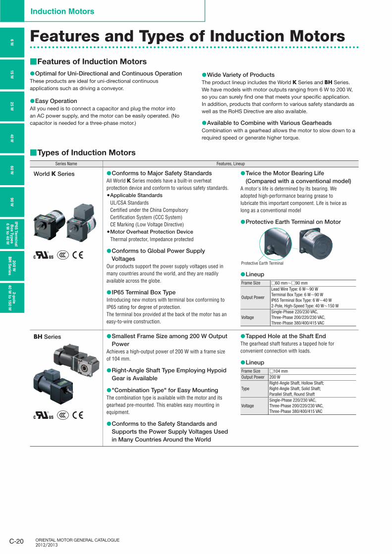
World K Series Conforms to Major Safety Standards ●All World K Series models have a built-in overheat protection device and conform to various safety standards.
Applicable Standards ●UL/CSA StandardsCertified under the China CompulsoryCertification System (CCC System)CE Marking (Low Voltage Directive)Motor Overheat Protection Device ●Thermal protector, Impedance protected
Conforms to Global Power Supply ●Voltages
Our products support the power supply voltages used in many countries around the world, and they are readily available across the globe.
IP65 Terminal Box Type ●Introducing new motors with terminal box conforming to IP65 rating for degree of protection.The terminal box provided at the back of the motor has an easy-to-wire construction.
Twice the Motor Bearing Life ●(Compared with a conventional model)
A motor's life is determined by its bearing. We adopted high-performance bearing grease to lubricate this important component. Life is twice as long as a conventional model
Protective Earth Terminal on Motor ●
Lineup ●Frame Size □60 mm∼□90 mm
Output Power
Lead Wire Type: 6 W∼90 WTerminal Box Type: 6 W∼90 WIP65 Terminal Box Type: 6 W∼40 W2-Pole, High-Speed Type: 40 W∼150 W
VoltageSingle-Phase 220/230 VAC,Three-Phase 200/220/230 VAC, Three-Phase 380/400/415 VAC
BH Series Smallest Frame Size among 200 W Output ●Power
Achieves a high-output power of 200 W with a frame size of 104 mm.
Right-Angle Shaft Type Employing Hypoid ●Gear is Available
"Combination Type" for Easy Mounting ●The combination type is available with the motor and its gearhead pre-mounted. This enables easy mounting in equipment.
Conforms to the Safety Standards and ●Supports the Power Supply Voltages Used in Many Countries Around the World
Tapped Hole at the Shaft End ●The gearhead shaft features a tapped hole for convenient connection with loads.
Lineup ●Frame Size □104 mmOutput Power 200 W
TypeRight-Angle Shaft, Hollow Shaft;Right-Angle Shaft, Solid Shaft;Parallel Shaft, Round Shaft
VoltageSingle-Phase 220/230 VAC,Three-Phase 200/220/230 VAC, Three-Phase 380/400/415 VAC
Protective Earth Terminal

C-21ContactTEL
Germany: 00800 22 55 66 22 UK/Ireland: 01256-347090 Italy: 02-93906346
France: 01 47 86 97 50 Other Countries: 00800 22 55 66 22
Standard AC MotorsIn
trod
uctio
nIn
du
ctio
n
Mo
t ors
Revers
ible
M
oto
rsE
lectro
mag
netic
B
rake M
oto
rsV
Serie
sTM
Serie
sTo
rqu
e M
oto
rs
Wate
rtigh
t, D
ust-R
esis
tan
t M
oto
rs
Rig
ht-A
ng
le
Gearh
ead
sB
rake P
ack
Acc
es
so
ries
Insta
llatio
n
Co
nsta
nt S
peed
Mo
tors
To
rqu
e M
oto
rs
Features of Gearheads ■
Easy Speed Reduction and Torque Increase ●Combination with a gearhead allows the motor to slow down to a required speed or generate higher torque.
Wide Variety of Products ●Gearheads come in various types including the long life, low noise gearhead and right-angle gearhead. Most gearheads are available with 20 different gear ratios from 1:3 to 1:180.
Gearheads can be used with pinion shaft type motors. ●World ● K Series gearheads are sold separately.The BH Series is a combination type that comes with the gearhead pre-assembled.
Gearhead Types ■
Types Features
Long Life, Low Noise GN-S Gearhead
Long Rated Life of 10000 Hours ● ✽
The GN-S gearhead achieves a long rated life of 10000 hours, twice the level of a conventional gearhead, by adopting a large, specially designed bearing and reinforced gears.
For the rated life time definition, refer to "Service Life of Gearheads" on ✽page G-35.
Low Noise Design ●The GN-S gearhead generates less noise thanks to gears with a special shape and surface machining assembled with the use of advanced technology.
Applicable Products ●6 W, 15 W, 25 W or 40 W GN pinion motor
30
25
20
15
10
5
025.0 40 63 100 160 250 400 630 1K 1.6K 2.5K 4K 6.3K 10K 16K
31.5 50 80 125 200 315 500 800 1.25K 2K 3.15K 5K 8K 12.5K 20K
Soun
d Pr
essu
re L
evel
[dB(
A)]
Frequency [Hz]
■: Long Life, Low Noise GN-S Gearhead 4IK25GN-AW2J/4GN120S■: GN-K Gearhead (Conventional Model) 4IK25GN-A/4GN120K[Measurement conditions]Load: 1.2 N•mDirection: ClockwiseMeasurement distance: 1 m (Measured in A-weighted sound pressure level)
Long Life GE-S Gearhead
Long Rated Life of 10000 Hours ● ✽
The GE-S gearhead achieves a long rated life of 10000 hours, twice the level of a conventional gearhead, by adopting a large, specially designed bearing and reinforced gears.
For the rated life time definition, refer to "Service Life of Gearheads" on ✽
page G-35.
The ● GE-S gearhead comes with a tapped hole at the tip of the shaft.
Applicable Products ●60 W or 90 W GE pinion motor
Right-Angle Gearheads➜ Page C-213
Ideal for Space Saving ●The output shaft of the gearhead is perpendicular to the motor shaft, enabling space saving.
Hollow Shaft Type and Solid Shaft Type are ●Available
Select the type that best suits your specific application.The ● GE pinion solid shaft type comes with a tapped hole at the shaft end.
Applicable Products ●World K Series25 W, 40 W, 60 W or 90 W Pinion Motor
Motor
Pinion ShaftGearhead
Highest Maximum Permissible torque,10,000 hours✽ of life and quiet operation.For more details on V Series see page C-149.
For the rated life time definition, refer to "Service Life of ✽
Gearheads" on page G-35.
High Strength, Long Life, Low NoiseV Series
ORIENTAL MOTOR GENERAL CATALOGUE 2012/2013
C-22
Induction Motors
6 W
15 W
25 W
40 W
60 W
90 W
IP65 T
erm
inal
Bo
x T
yp
es
6 W
to 4
0 W
20
0 W
BH
Serie
s2-p
ole
40 W
to 1
50 W
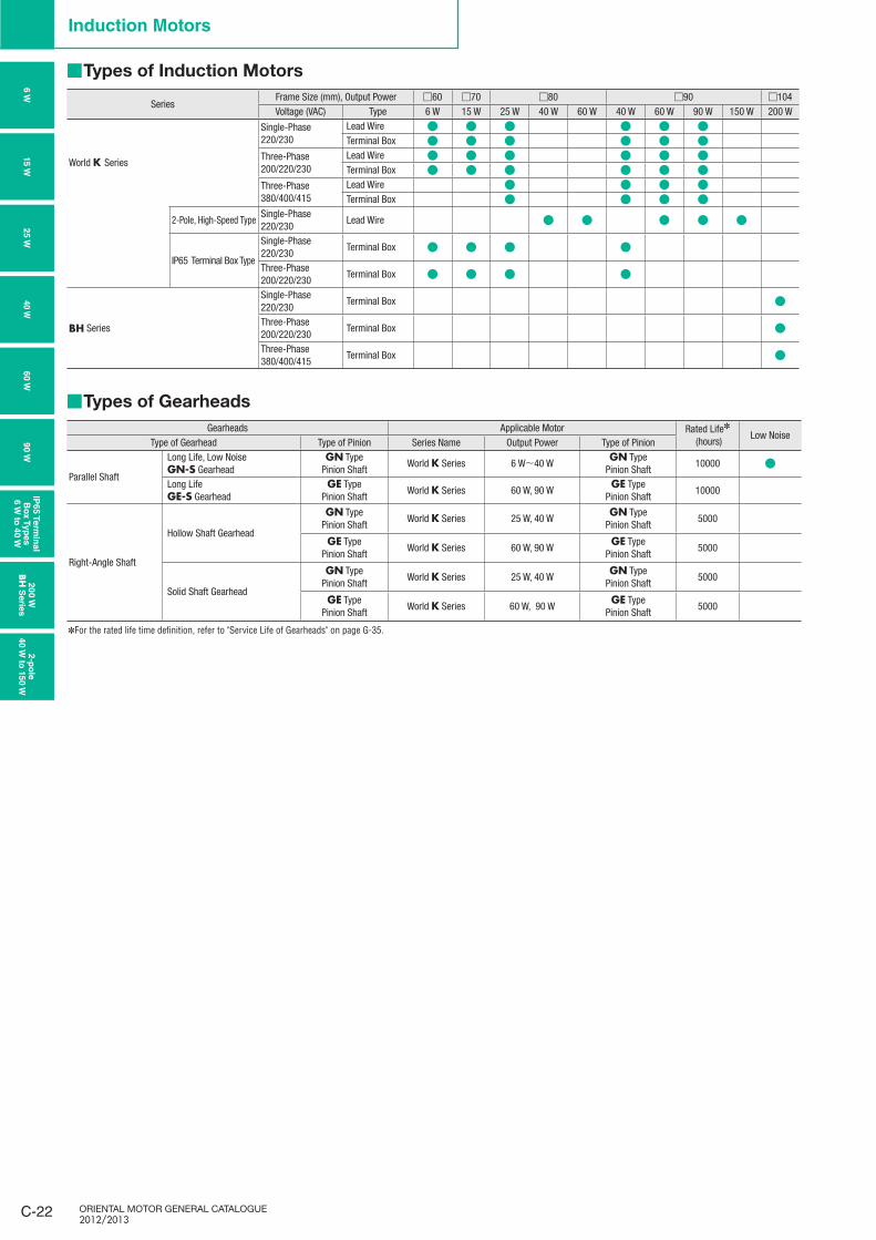
Types of Induction Motors ■
SeriesFrame Size (mm), Output Power □60 □70 □80 □90 □104Voltage (VAC) Type 6 W 15 W 25 W 40 W 60 W 40 W 60 W 90 W 150 W 200 W
World K Series
Single-Phase 220/230
Lead Wire ● ● ● ● ● ●Terminal Box ● ● ● ● ● ●
Three-Phase200/220/230
Lead Wire ● ● ● ● ● ●Terminal Box ● ● ● ● ● ●
Three-Phase380/400/415
Lead Wire ● ● ● ●Terminal Box ● ● ● ●
2-Pole, High-Speed TypeSingle-Phase 220/230
Lead Wire ● ● ● ● ●
IP65 Terminal Box Type
Single-Phase 220/230
Terminal Box ● ● ● ●
Three-Phase 200/220/230
Terminal Box ● ● ● ●
BH Series
Single-Phase 220/230
Terminal Box ●
Three-Phase 200/220/230
Terminal Box ●
Three-Phase 380/400/415
Terminal Box ●
Types of Gearheads ■
Gearheads Applicable Motor Rated Life✽
(hours) Low Noise
Type of Gearhead Type of Pinion Series Name Output Power Type of Pinion
Parallel Shaft
Long Life, Low Noise GN-S Gearhead
GN TypePinion Shaft
World K Series 6 W∼40 WGN Type
Pinion Shaft10000 ●
Long Life GE-S Gearhead
GE TypePinion Shaft
World K Series 60 W, 90 WGE Type
Pinion Shaft10000
Right-Angle Shaft
Hollow Shaft Gearhead
GN TypePinion Shaft
World K Series 25 W, 40 WGN Type
Pinion Shaft5000
GE TypePinion Shaft
World K Series 60 W, 90 WGE Type
Pinion Shaft5000
Solid Shaft Gearhead
GN TypePinion Shaft
World K Series 25 W, 40 WGN Type
Pinion Shaft5000
GE TypePinion Shaft
World K Series 60 W, 90 WGE Type
Pinion Shaft5000
For the rated life time definition, refer to "Service Life of Gearheads" on ✽ page G-35.
C-23ContactTEL
Germany: 00800 22 55 66 22 UK/Ireland: 01256-347090 Italy: 02-93906346
France: 01 47 86 97 50 Other Countries: 00800 22 55 66 22
Standard AC MotorsIn
trod
uctio
nIn
du
ctio
n
Mo
t ors
Revers
ible
M
oto
rsE
lectro
mag
netic
B
rake M
oto
rsV
Serie
sTM
Serie
sTo
rqu
e M
oto
rs
Wate
rtigh
t, D
ust-R
esis
tan
t M
oto
rs
Rig
ht-A
ng
le
Gearh
ead
sB
rake P
ack
Acc
es
so
ries
Insta
llatio
n
Co
nsta
nt S
peed
Mo
tors
To
rqu
e M
oto
rs
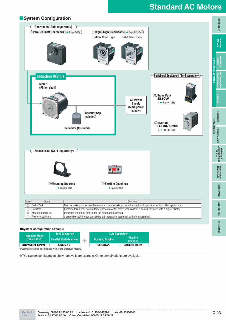
System Configuration ■
Gearheads (Sold separately)
Motor
(Pinion shaft)
Induction Motors
Capacitor (Included)
Capacitor Cap
(Included)
AC Power
Supply
(Main power
supply)
① Brake PackSB50W( ➜ Page C-229)
② InvertersFE100/FE200( ➜ Page D-136)
Peripheral Equipment (Sold separately)
③ Mounting Brackets
( ➜ Page C-240)
④ Flexible Couplings
( ➜ Page C-245)
Number Name Overview① Brake Pack Use the brake pack to stop the motor instantaneously, perform bi-directional operation, and for other applications.② Inverters Combine this inverter with a three-phase motor for easy speed control. It comes equipped with a digital display.③ Mounting Brackets Dedicated mounting bracket for the motor and gearhead.④ Flexible Couplings Clamp type coupling for connecting the motor/gearhead shaft with the driven shaft.
●System Confi guration Example
Induction Motor
(Pinion shaft)
Sold Separately Sold Separately
Parallel Shaft Gearhead
Mounting BracketFlexible
Coupling
4IK25GN-CW2E 4GN25S SOL4M5 MCL301012●Gearheads cannot be combined with round shaft type motors.
●The system confi guration shown above is an example. Other combinations are available.
Parallel Shaft Gearheads ( ➜ Page C-21) Right-Angle Gearheads ( ➜ Page C-213)
Hollow Shaft Type Solid Shaft Type
Accessories (Sold separately)
ORIENTAL MOTOR GENERAL CATALOGUE 2012/2013
C-24
Induction Motors
6 W
15 W
25 W
40 W
60 W
90 W
IP65 T
erm
inal
Bo
x T
yp
es
6 W
to 4
0 W
20
0 W
BH
Serie
s2-p
ole
40 W
to 1
50 W
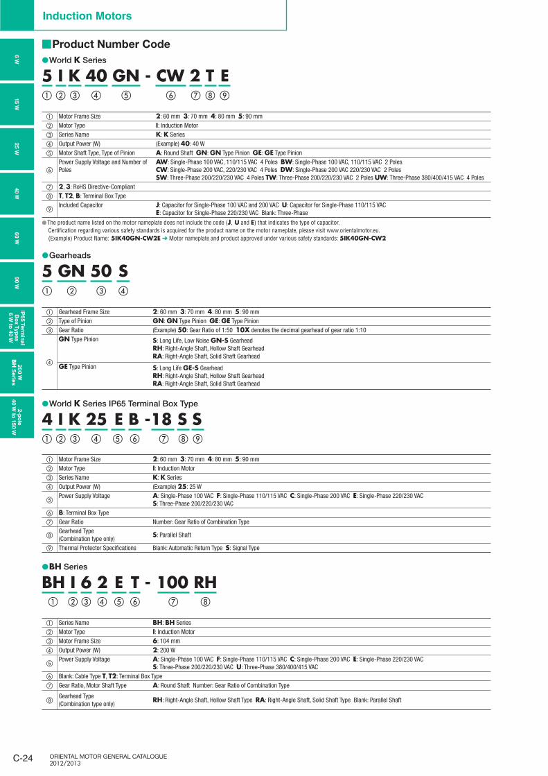
Product Number Code ■
World ● K Series
5 I K 40 GN - CW 2 T E① ② ③ ④ ⑥⑤ ⑧ ⑨⑦
① Motor Frame Size 2: 60 mm 3: 70 mm 4: 80 mm 5: 90 mm② Motor Type I: Induction Motor③ Series Name K: K Series④ Output Power (W) (Example) 40: 40 W⑤ Motor Shaft Type, Type of Pinion A: Round Shaft GN: GN Type Pinion GE: GE Type Pinion
⑥Power Supply Voltage and Number of Poles
AW: Single-Phase 100 VAC, 110/115 VAC 4 Poles BW: Single-Phase 100 VAC, 110/115 VAC 2 Poles CW: Single-Phase 200 VAC, 220/230 VAC 4 Poles DW: Single-Phase 200 VAC 220/230 VAC 2 PolesSW: Three-Phase 200/220/230 VAC 4 Poles TW: Three-Phase 200/220/230 VAC 2 Poles UW: Three-Phase 380/400/415 VAC 4 Poles
⑦ 2, 3: RoHS Directive-Compliant⑧ T, T2, B: Terminal Box Type
⑨Included Capacitor J: Capacitor for Single-Phase 100 VAC and 200 VAC U: Capacitor for Single-Phase 110/115 VAC
E: Capacitor for Single-Phase 220/230 VAC Blank: Three-Phase
The product name listed on the motor nameplate does not include the code ( ● J, U and E) that indicates the type of capacitor.Certification regarding various safety standards is acquired for the product name on the motor nameplate, please visit www.orientalmotor.eu. (Example) Product Name: 5IK40GN-CW2E ➜ Motor nameplate and product approved under various safety standards: 5IK40GN-CW2
Gearheads ●
5 GN 50 S① ② ③ ④
① Gearhead Frame Size 2: 60 mm 3: 70 mm 4: 80 mm 5: 90 mm② Type of Pinion GN: GN Type Pinion GE: GE Type Pinion③ Gear Ratio (Example) 50: Gear Ratio of 1:50 10X denotes the decimal gearhead of gear ratio 1:10
④
GN Type Pinion S: Long Life, Low Noise GN-S GearheadRH: Right-Angle Shaft, Hollow Shaft GearheadRA: Right-Angle Shaft, Solid Shaft Gearhead
GE Type Pinion S: Long Life GE-S GearheadRH: Right-Angle Shaft, Hollow Shaft GearheadRA: Right-Angle Shaft, Solid Shaft Gearhead
World ● K Series IP65 Terminal Box Type
4 I K 25 E B -18 S S ① ② ③ ④ ⑥⑤ ⑧ ⑨⑦
① Motor Frame Size 2: 60 mm 3: 70 mm 4: 80 mm 5: 90 mm② Motor Type I: Induction Motor③ Series Name K: K Series④ Output Power (W) (Example) 25: 25 W
⑤Power Supply Voltage A: Single-Phase 100 VAC F: Single-Phase 110/115 VAC C: Single-Phase 200 VAC E: Single-Phase 220/230 VAC
S: Three-Phase 200/220/230 VAC⑥ B: Terminal Box Type⑦ Gear Ratio Number: Gear Ratio of Combination Type
⑧Gearhead Type(Combination type only)
S: Parallel Shaft
⑨ Thermal Protector Specifications Blank: Automatic Return Type S: Signal Type
BH ● Series
BH I 6 2 E T - 100 RH① ⑧⑦② ③ ④ ⑥⑤
① Series Name BH: BH Series② Motor Type I: Induction Motor③ Motor Frame Size 6: 104 mm④ Output Power (W) 2: 200 W
⑤Power Supply Voltage A: Single-Phase 100 VAC F: Single-Phase 110/115 VAC C: Single-Phase 200 VAC E: Single-Phase 220/230 VAC
S: Three-Phase 200/220/230 VAC U: Three-Phase 380/400/415 VAC⑥ Blank: Cable Type T, T2: Terminal Box Type⑦ Gear Ratio, Motor Shaft Type A: Round Shaft Number: Gear Ratio of Combination Type
⑧Gearhead Type(Combination type only)
RH: Right-Angle Shaft, Hollow Shaft Type RA: Right-Angle Shaft, Solid Shaft Type Blank: Parallel Shaft
C-25ContactTEL
Germany: 00800 22 55 66 22 UK/Ireland: 01256-347090 Italy: 02-93906346
France: 01 47 86 97 50 Other Countries: 00800 22 55 66 22
Standard AC MotorsIn
trod
uctio
nIn
du
ctio
n
Mo
t ors
Revers
ible
M
oto
rsE
lectro
mag
netic
B
rake M
oto
rsV
Serie
sTM
Serie
sTo
rqu
e M
oto
rs
Wate
rtigh
t, D
ust-R
esis
tan
t M
oto
rs
Rig
ht-A
ng
le
Gearh
ead
sB
rake P
ack
Acc
es
so
ries
Insta
llatio
n
Co
nsta
nt S
peed
Mo
tors
To
rqu
e M
oto
rs
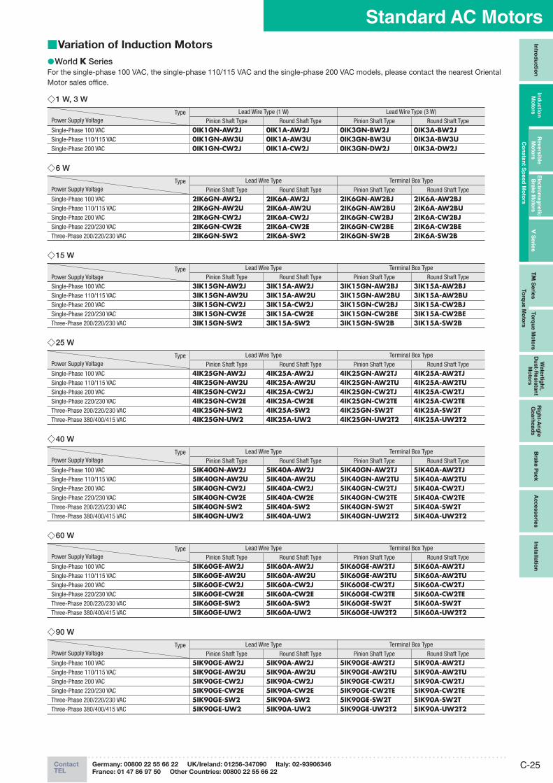
Variation of Induction Motors ■
World ● K SeriesFor the single-phase 100 VAC, the single-phase 110/115 VAC and the single-phase 200 VAC models, please contact the nearest Oriental Motor sales office.
1 W, 3 W ◇
TypePower Supply Voltage
Lead Wire Type (1 W) Lead Wire Type (3 W)Pinion Shaft Type Round Shaft Type Pinion Shaft Type Round Shaft Type
Single-Phase 100 VAC 0IK1GN-AW2J 0IK1A-AW2J 0IK3GN-BW2J 0IK3A-BW2JSingle-Phase 110/115 VAC 0IK1GN-AW3U 0IK1A-AW3U 0IK3GN-BW3U 0IK3A-BW3USingle-Phase 200 VAC 0IK1GN-CW2J 0IK1A-CW2J 0IK3GN-DW2J 0IK3A-DW2J
6 W ◇
TypePower Supply Voltage
Lead Wire Type Terminal Box TypePinion Shaft Type Round Shaft Type Pinion Shaft Type Round Shaft Type
Single-Phase 100 VAC 2IK6GN-AW2J 2IK6A-AW2J 2IK6GN-AW2BJ 2IK6A-AW2BJSingle-Phase 110/115 VAC 2IK6GN-AW2U 2IK6A-AW2U 2IK6GN-AW2BU 2IK6A-AW2BUSingle-Phase 200 VAC 2IK6GN-CW2J 2IK6A-CW2J 2IK6GN-CW2BJ 2IK6A-CW2BJSingle-Phase 220/230 VAC 2IK6GN-CW2E 2IK6A-CW2E 2IK6GN-CW2BE 2IK6A-CW2BEThree-Phase 200/220/230 VAC 2IK6GN-SW2 2IK6A-SW2 2IK6GN-SW2B 2IK6A-SW2B
15 W ◇
TypePower Supply Voltage
Lead Wire Type Terminal Box TypePinion Shaft Type Round Shaft Type Pinion Shaft Type Round Shaft Type
Single-Phase 100 VAC 3IK15GN-AW2J 3IK15A-AW2J 3IK15GN-AW2BJ 3IK15A-AW2BJSingle-Phase 110/115 VAC 3IK15GN-AW2U 3IK15A-AW2U 3IK15GN-AW2BU 3IK15A-AW2BUSingle-Phase 200 VAC 3IK15GN-CW2J 3IK15A-CW2J 3IK15GN-CW2BJ 3IK15A-CW2BJSingle-Phase 220/230 VAC 3IK15GN-CW2E 3IK15A-CW2E 3IK15GN-CW2BE 3IK15A-CW2BEThree-Phase 200/220/230 VAC 3IK15GN-SW2 3IK15A-SW2 3IK15GN-SW2B 3IK15A-SW2B
25 W ◇
TypePower Supply Voltage
Lead Wire Type Terminal Box TypePinion Shaft Type Round Shaft Type Pinion Shaft Type Round Shaft Type
Single-Phase 100 VAC 4IK25GN-AW2J 4IK25A-AW2J 4IK25GN-AW2TJ 4IK25A-AW2TJSingle-Phase 110/115 VAC 4IK25GN-AW2U 4IK25A-AW2U 4IK25GN-AW2TU 4IK25A-AW2TUSingle-Phase 200 VAC 4IK25GN-CW2J 4IK25A-CW2J 4IK25GN-CW2TJ 4IK25A-CW2TJSingle-Phase 220/230 VAC 4IK25GN-CW2E 4IK25A-CW2E 4IK25GN-CW2TE 4IK25A-CW2TEThree-Phase 200/220/230 VAC 4IK25GN-SW2 4IK25A-SW2 4IK25GN-SW2T 4IK25A-SW2TThree-Phase 380/400/415 VAC 4IK25GN-UW2 4IK25A-UW2 4IK25GN-UW2T2 4IK25A-UW2T2
40 W ◇
TypePower Supply Voltage
Lead Wire Type Terminal Box TypePinion Shaft Type Round Shaft Type Pinion Shaft Type Round Shaft Type
Single-Phase 100 VAC 5IK40GN-AW2J 5IK40A-AW2J 5IK40GN-AW2TJ 5IK40A-AW2TJSingle-Phase 110/115 VAC 5IK40GN-AW2U 5IK40A-AW2U 5IK40GN-AW2TU 5IK40A-AW2TUSingle-Phase 200 VAC 5IK40GN-CW2J 5IK40A-CW2J 5IK40GN-CW2TJ 5IK40A-CW2TJSingle-Phase 220/230 VAC 5IK40GN-CW2E 5IK40A-CW2E 5IK40GN-CW2TE 5IK40A-CW2TEThree-Phase 200/220/230 VAC 5IK40GN-SW2 5IK40A-SW2 5IK40GN-SW2T 5IK40A-SW2TThree-Phase 380/400/415 VAC 5IK40GN-UW2 5IK40A-UW2 5IK40GN-UW2T2 5IK40A-UW2T2
60 W ◇
TypePower Supply Voltage
Lead Wire Type Terminal Box TypePinion Shaft Type Round Shaft Type Pinion Shaft Type Round Shaft Type
Single-Phase 100 VAC 5IK60GE-AW2J 5IK60A-AW2J 5IK60GE-AW2TJ 5IK60A-AW2TJSingle-Phase 110/115 VAC 5IK60GE-AW2U 5IK60A-AW2U 5IK60GE-AW2TU 5IK60A-AW2TUSingle-Phase 200 VAC 5IK60GE-CW2J 5IK60A-CW2J 5IK60GE-CW2TJ 5IK60A-CW2TJSingle-Phase 220/230 VAC 5IK60GE-CW2E 5IK60A-CW2E 5IK60GE-CW2TE 5IK60A-CW2TEThree-Phase 200/220/230 VAC 5IK60GE-SW2 5IK60A-SW2 5IK60GE-SW2T 5IK60A-SW2TThree-Phase 380/400/415 VAC 5IK60GE-UW2 5IK60A-UW2 5IK60GE-UW2T2 5IK60A-UW2T2
90 W ◇
TypePower Supply Voltage
Lead Wire Type Terminal Box TypePinion Shaft Type Round Shaft Type Pinion Shaft Type Round Shaft Type
Single-Phase 100 VAC 5IK90GE-AW2J 5IK90A-AW2J 5IK90GE-AW2TJ 5IK90A-AW2TJSingle-Phase 110/115 VAC 5IK90GE-AW2U 5IK90A-AW2U 5IK90GE-AW2TU 5IK90A-AW2TUSingle-Phase 200 VAC 5IK90GE-CW2J 5IK90A-CW2J 5IK90GE-CW2TJ 5IK90A-CW2TJSingle-Phase 220/230 VAC 5IK90GE-CW2E 5IK90A-CW2E 5IK90GE-CW2TE 5IK90A-CW2TEThree-Phase 200/220/230 VAC 5IK90GE-SW2 5IK90A-SW2 5IK90GE-SW2T 5IK90A-SW2TThree-Phase 380/400/415 VAC 5IK90GE-UW2 5IK90A-UW2 5IK90GE-UW2T2 5IK90A-UW2T2
ORIENTAL MOTOR GENERAL CATALOGUE 2012/2013
C-26
Induction Motors
6 W
15 W
25 W
40 W
60 W
90 W
IP65 T
erm
inal
Bo
x T
yp
es
6 W
to 4
0 W
20
0 W
BH
Serie
s2-p
ole
40 W
to 1
50 W
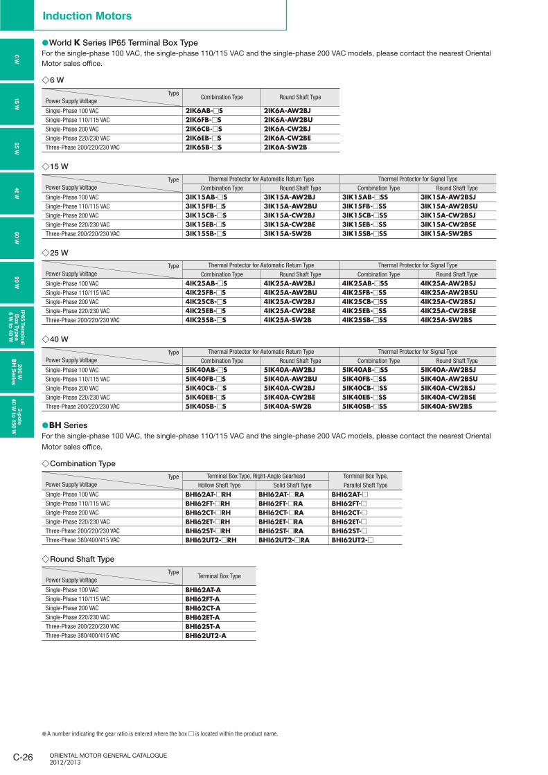
World ● K Series IP65 Terminal Box TypeFor the single-phase 100 VAC, the single-phase 110/115 VAC and the single-phase 200 VAC models, please contact the nearest Oriental Motor sales office.
6 W ◇
TypePower Supply Voltage
Combination Type Round Shaft Type
Single-Phase 100 VAC 2IK6AB-□S 2IK6A-AW2BJSingle-Phase 110/115 VAC 2IK6FB-□S 2IK6A-AW2BUSingle-Phase 200 VAC 2IK6CB-□S 2IK6A-CW2BJSingle-Phase 220/230 VAC 2IK6EB-□S 2IK6A-CW2BEThree-Phase 200/220/230 VAC 2IK6SB-□S 2IK6A-SW2B
15 W ◇
TypePower Supply Voltage
Thermal Protector for Automatic Return Type Thermal Protector for Signal TypeCombination Type Round Shaft Type Combination Type Round Shaft Type
Single-Phase 100 VAC 3IK15AB-□S 3IK15A-AW2BJ 3IK15AB-□SS 3IK15A-AW2BSJSingle-Phase 110/115 VAC 3IK15FB-□S 3IK15A-AW2BU 3IK15FB-□SS 3IK15A-AW2BSUSingle-Phase 200 VAC 3IK15CB-□S 3IK15A-CW2BJ 3IK15CB-□SS 3IK15A-CW2BSJSingle-Phase 220/230 VAC 3IK15EB-□S 3IK15A-CW2BE 3IK15EB-□SS 3IK15A-CW2BSEThree-Phase 200/220/230 VAC 3IK15SB-□S 3IK15A-SW2B 3IK15SB-□SS 3IK15A-SW2BS
25 W ◇
TypePower Supply Voltage
Thermal Protector for Automatic Return Type Thermal Protector for Signal TypeCombination Type Round Shaft Type Combination Type Round Shaft Type
Single-Phase 100 VAC 4IK25AB-□S 4IK25A-AW2BJ 4IK25AB-□SS 4IK25A-AW2BSJSingle-Phase 110/115 VAC 4IK25FB-□S 4IK25A-AW2BU 4IK25FB-□SS 4IK25A-AW2BSUSingle-Phase 200 VAC 4IK25CB-□S 4IK25A-CW2BJ 4IK25CB-□SS 4IK25A-CW2BSJSingle-Phase 220/230 VAC 4IK25EB-□S 4IK25A-CW2BE 4IK25EB-□SS 4IK25A-CW2BSEThree-Phase 200/220/230 VAC 4IK25SB-□S 4IK25A-SW2B 4IK25SB-□SS 4IK25A-SW2BS
40 W ◇
TypePower Supply Voltage
Thermal Protector for Automatic Return Type Thermal Protector for Signal TypeCombination Type Round Shaft Type Combination Type Round Shaft Type
Single-Phase 100 VAC 5IK40AB-□S 5IK40A-AW2BJ 5IK40AB-□SS 5IK40A-AW2BSJSingle-Phase 110/115 VAC 5IK40FB-□S 5IK40A-AW2BU 5IK40FB-□SS 5IK40A-AW2BSUSingle-Phase 200 VAC 5IK40CB-□S 5IK40A-CW2BJ 5IK40CB-□SS 5IK40A-CW2BSJSingle-Phase 220/230 VAC 5IK40EB-□S 5IK40A-CW2BE 5IK40EB-□SS 5IK40A-CW2BSEThree-Phase 200/220/230 VAC 5IK40SB-□S 5IK40A-SW2B 5IK40SB-□SS 5IK40A-SW2BS
BH ● SeriesFor the single-phase 100 VAC, the single-phase 110/115 VAC and the single-phase 200 VAC models, please contact the nearest Oriental
Motor sales office.
Combination Type ◇
TypePower Supply Voltage
Terminal Box Type, Right-Angle Gearhead Terminal Box Type,Hollow Shaft Type Solid Shaft Type Parallel Shaft Type
Single-Phase 100 VAC BHI62AT-□RH BHI62AT-□RA BHI62AT-□Single-Phase 110/115 VAC BHI62FT-□RH BHI62FT-□RA BHI62FT-□Single-Phase 200 VAC BHI62CT-□RH BHI62CT-□RA BHI62CT-□Single-Phase 220/230 VAC BHI62ET-□RH BHI62ET-□RA BHI62ET-□Three-Phase 200/220/230 VAC BHI62ST-□RH BHI62ST-□RA BHI62ST-□Three-Phase 380/400/415 VAC BHI62UT2-□RH BHI62UT2-□RA BHI62UT2-□
Round Shaft Type ◇
TypePower Supply Voltage
Terminal Box Type
Single-Phase 100 VAC BHI62AT-ASingle-Phase 110/115 VAC BHI62FT-ASingle-Phase 200 VAC BHI62CT-ASingle-Phase 220/230 VAC BHI62ET-AThree-Phase 200/220/230 VAC BHI62ST-AThree-Phase 380/400/415 VAC BHI62UT2-A
A number indicating the gear ratio is entered where the box ● □ is located within the product name.
C-27ContactTEL
Germany: 00800 22 55 66 22 UK/Ireland: 01256-347090 Italy: 02-93906346
France: 01 47 86 97 50 Other Countries: 00800 22 55 66 22
Standard AC MotorsIn
trod
uctio
nIn
du
ctio
n
Mo
t ors
Revers
ible
M
oto
rsE
lectro
mag
netic
B
rake M
oto
rsV
Serie
sTM
Serie
sTo
rqu
e M
oto
rs
Wate
rtigh
t, D
ust-R
esis
tan
t M
oto
rs
Rig
ht-A
ng
le
Gearh
ead
sB
rake P
ack
Acc
es
so
ries
Insta
llatio
n
Co
nsta
nt S
peed
Mo
tors
To
rqu
e M
oto
rs
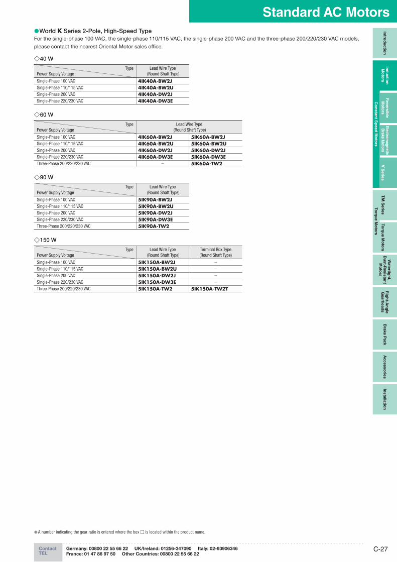
World ● K Series 2-Pole, High-Speed TypeFor the single-phase 100 VAC, the single-phase 110/115 VAC, the single-phase 200 VAC and the three-phase 200/220/230 VAC models,
please contact the nearest Oriental Motor sales office.
40 W ◇
TypePower Supply Voltage
Lead Wire Type (Round Shaft Type)
Single-Phase 100 VAC 4IK40A-BW2JSingle-Phase 110/115 VAC 4IK40A-BW2USingle-Phase 200 VAC 4IK40A-DW2JSingle-Phase 220/230 VAC 4IK40A-DW3E
60 W ◇
TypePower Supply Voltage
Lead Wire Type (Round Shaft Type)
Single-Phase 100 VAC 4IK60A-BW2J 5IK60A-BW2JSingle-Phase 110/115 VAC 4IK60A-BW2U 5IK60A-BW2USingle-Phase 200 VAC 4IK60A-DW2J 5IK60A-DW2JSingle-Phase 220/230 VAC 4IK60A-DW3E 5IK60A-DW3EThree-Phase 200/220/230 VAC − 5IK60A-TW2
90 W ◇
TypePower Supply Voltage
Lead Wire Type (Round Shaft Type)
Single-Phase 100 VAC 5IK90A-BW2JSingle-Phase 110/115 VAC 5IK90A-BW2USingle-Phase 200 VAC 5IK90A-DW2JSingle-Phase 220/230 VAC 5IK90A-DW3EThree-Phase 200/220/230 VAC 5IK90A-TW2
150 W ◇
TypePower Supply Voltage
Lead Wire Type (Round Shaft Type)
Terminal Box Type(Round Shaft Type)
Single-Phase 100 VAC 5IK150A-BW2J −
Single-Phase 110/115 VAC 5IK150A-BW2U −
Single-Phase 200 VAC 5IK150A-DW2J −
Single-Phase 220/230 VAC 5IK150A-DW3E −
Three-Phase 200/220/230 VAC 5IK150A-TW2 5IK150A-TW2T
A number indicating the gear ratio is entered where the box ● □ is located within the product name.
ORIENTAL MOTOR GENERAL CATALOGUE 2012/2013
C-28
Induction Motors
6 W
15 W
25 W
40 W
60 W
90 W
IP65 T
erm
inal
Bo
x T
yp
es
6 W
to 4
0 W
20
0 W
BH
Serie
s2-p
ole
40 W
to 1
50 W
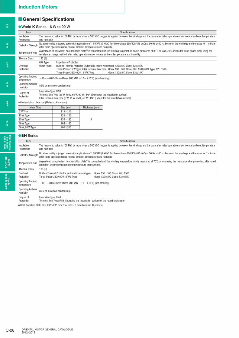
■ General Specifications
World ● K Series - 6 W to 90 WItem Specifications
Insulation Resistance
The measured value is 100 MΩ or more when a 500 VDC megger is applied between the windings and the case after rated operation under normal ambient temperature and humidity.
Dielectric StrengthNo abnormality is judged even with application of 1.5 kVAC (2 kVAC for three-phase 380/400/415 VAC) at 50 Hz or 60 Hz between the windings and the case for 1 minute after rated operation under normal ambient temperature and humidity.
Temperature RiseA gearhead or equivalent heat radiation plate✽ is connected and the winding temperature rise is measured at 80˚C or less (70˚C or less for three-phase type) using the resistance change method after rated operation under normal ambient temperature and humidity.
Thermal Class 130 (B)
Overheat Protection
6 W Type Impedance ProtectedOther Types Built-In Thermal Protector (Automatic return type) Open: 130±5˚C, Close: 82±15˚C Three-Phase 15 W Type, IP65 Terminal Box Type Open: 130±5˚C, Close: 90±15˚C (40 W Type: 82±15˚C) Three-Phase 380/400/415 VAC Type Open: 130±5˚C, Close: 83±15˚C
Operating Ambient Temperature
−10∼+40˚C (Three-Phase 200 VAC: −10∼+50˚C) (non-freezing)
Operating Ambient Humidity
85% or less (non-condensing)
Degree of Protection
Lead Wire Type: IP20Terminal Box Type (25 W, 40 W, 60 W, 90 W): IP54 (Except for the installation surface)IP65 Terminal Box Type (6 W, 15 W, 25 W, 40 W): IP65 (Except for the installation surface)
✽Heat radiation plate size (Material: Aluminum)
Motor Type Size (mm) Thickness (mm)6 W Type 115×115
515 W Type 125×12525 W Type 135×13540 W Type 165×16560 W, 90 W Type 200×200
BH ● SeriesItem Specifications
Insulation Resistance
The measured value is 100 MΩ or more when a 500 VDC megger is applied between the windings and the case after rated operation under normal ambient temperature and humidity.
Dielectric StrengthNo abnormality is judged even with application of 1.5 kVAC (2 kVAC for three-phase 380/400/415 VAC) at 50 Hz or 60 Hz between the windings and the case for 1 minute after rated operation under normal ambient temperature and humidity.
Temperature RiseA gearhead or equivalent heat radiation plate✽ is connected and the winding temperature rise is measured at 70˚C or less using the resistance change method after rated operation under normal ambient temperature and humidity.
Thermal Class 130 (B)
Overheat Protection
Built-In Thermal Protector (Automatic return type) Open: 150±5˚C, Close: 96±15˚CThree-Phase 380/400/415 VAC Type Open: 130±5˚C, Close: 83±15˚C
Operating Ambient Temperature
−10∼+40˚C (Three-Phase 200 VAC: −10∼+50˚C) (non-freezing)
Operating Ambient Humidity
85% or less (non-condensing)
Degree of Protection
Lead Wire Type: IP40Terminal Box Type: IP54 (Excluding the installation surface of the round shaft type)
✽ Heat Radiation Plate Size: 230×230 mm, Thickness: 5 mm (Material: Aluminum)
C-29ContactTEL
Germany: 00800 22 55 66 22 UK/Ireland: 01256-347090 Italy: 02-93906346
France: 01 47 86 97 50 Other Countries: 00800 22 55 66 22
Standard AC MotorsIn
trod
uctio
nIn
du
ctio
n
Mo
t ors
Revers
ible
M
oto
rsE
lectro
mag
netic
B
rake M
oto
rsV
Serie
sTM
Serie
sTo
rqu
e M
oto
rs
Wate
rtigh
t, D
ust-R
esis
tan
t M
oto
rs
Rig
ht-A
ng
le
Gearh
ead
sB
rake P
ack
Acc
es
so
ries
Insta
llatio
n
Co
nsta
nt S
peed
Mo
tors
To
rqu
e M
oto
rs
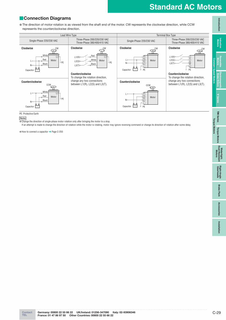
Connection Diagrams ■
The direction of motor rotation is as viewed from the shaft end of the motor. CW represents the clockwise direction, while CCW ●represents the counterclockwise direction.
Lead Wire Type Terminal Box Type
Counterclockwise
ClockwiseClockwise Clockwise
Counterclockwise
Single-Phase 220/230 VAC Single-Phase 220/230 VAC Three-Phase 200/220/230 VACThree-Phase 380/400/415 VAC
Three-Phase 200/220/230 VACThree-Phase 380/400/415 VAC
Counterclockwise Counterclockwise
Clockwise CW
U1U2Z2
Capacitor
LN
Motor
PE
U1U2Z2
L
NMotor
Capacitor
CCW
PE
U1U2Z2
Red
White
BlackMotor
PE
CW
L1(R)
L2(S)
L3(T)
UVW
L1(R)L2(S)L3(T)
Motor
CW
PECapacitor
Black
RedL
N
White
MotorPE
CW
White
RedL
NBlack
MotorPE
Capacitor
CCW
To change the rotation direction, change any two connections between L1(R), L2(S) and L3(T).
To change the rotation direction, change any two connections between L1(R), L2(S) and L3(T).
PE: Protective Earth
NoteChange the direction of single-phase motor rotation only after bringing the motor to a stop. ●If an attempt is made to change the direction of rotation while the motor is rotating, motor may ignore reversing command or change its direction of rotation after some delay.
How to connect a capacitor ● ➜ Page C-255

ORIENTAL MOTOR GENERAL CATALOGUE 2012/2013
C-30 Page Features C-20 / System Configuration C-23 / Product Line C-30 / Specifications C-30
Dimensions C-31 / Connection Diagrams C-29
Induction Motors
Product Line ■
Motors ●
TypeProduct Name
Pinion Shaft Type Round Shaft Type
Lead Wire2IK6GN-CW2E 2IK6A-CW2E2IK6GN-SW2 2IK6A-SW2
Terminal Box2IK6GN-CW2BE 2IK6A-CW2BE2IK6GN-SW2B 2IK6A-SW2B
Parallel Shaft Gearheads (Sold separately) ●These products can be attached to pinion shafts.
Gearhead Type Gearhead Product Name Gear Ratio
Parallel Shaft
Long Life, Low Noise GN-S Gearhead
2GN□S 3∼1802GN10XS (Decimal gearhead)
A number indicating the gear ratio is entered where the box ● □ is located within the gearhead product name.
Induction Motors
6 W□60 mm
Gearheads shown in the photograph are sold separately.
Specifications – Continuous Rating ■
Product Name and TypeUpper Product Name: Pinion Shaft Type
Lower Product Name in ( ): Round Shaft Type
Output Power
Voltage Frequency CurrentStarting Torque
Rated Torque
Rated Speed Capacitor
Lead Wire TypeDimensions ①
Terminal Box TypeDimensions ② W VAC Hz A mN·m mN·m r/min μF
2IK6GN-CW2E(2IK6A-CW2E)
2IK6GN-CW2BE(2IK6A-CW2BE)
6Single-Phase 220
50 0.103 38 49 1150
0.660 0.091 40 41 1450
Single-Phase 23050 0.107 45 49 120060 0.094 40 41 1450
2IK6GN-SW2(2IK6A-SW2)
2IK6GN-SW2B(2IK6A-SW2B)
6Three-Phase 200
50 0.081 49 49 1200
−60 0.072 41 41 1400
Three-Phase 220 60 0.076 41 41 1500Three-Phase 230 60 0.079 41 41 1500
The product name listed on the motor nameplate does not include the code ( ● E) that indicates the type of capacitor.Certification regarding various safety standards is acquired for the product name on the motor nameplate, please visit www.orientalmotor.eu .Safety standards ● ➜ Page H-2
: These products are impedance protected.
Degree of Protection ●
TypeProduct Name
Degree of ProtectionPinion Shaft Type Round Shaft Type
Lead Wire 2IK6GN-CW2E2IK6GN-SW2
2IK6A-CW2E2IK6A-SW2
IP20
Terminal Box 2IK6GN-CW2BE2IK6GN-SW2B
2IK6A-CW2BE✽
2IK6A-SW2B✽ IP65
E ✽ xcluding the installation surface of the round shaft type.
Terminal Box TypeLead Wire Type
The following items are included in each product.Motor, Capacitor✽, Capacitor Cap✽, Operating Manual
Single-phase motors only ✽
The following items are included in each product.Gearhead, Mounting Screws, Operating Manual
Highest Maximum Permissible torque, 10,000 hours✽ of life and quiet operation. For more details on V Series see page C-149.
For the rated life time definition, refer to "Service Life of ✽
Gearheads" on page G-35.
High Strength, Long Life, Low NoiseV Series
6 W
15 W
25 W
40 W
60 W
90 W
IP65 T
erm
inal
Bo
x T
yp
es
6 W
to 4
0 W
20
0 W
BH
Serie
s2-p
ole
40 W
to 1
50 W
C-31ContactTEL
Germany: 00800 22 55 66 22 UK/Ireland: 01256-347090 Italy: 02-93906346
France: 01 47 86 97 50 Other Countries: 00800 22 55 66 22
Standard AC MotorsIn
trod
uctio
nIn
du
ctio
n
Mo
t ors
Revers
ible
M
oto
rsE
lectro
mag
netic
B
rake M
oto
rsV
Serie
sTM
Serie
sTo
rqu
e M
oto
rs
Wate
rtigh
t, D
ust-R
esis
tan
t M
oto
rs
Rig
ht-A
ng
le
Gearh
ead
sB
rake P
ack
Acc
es
so
ries
Insta
llatio
n
Co
nsta
nt S
peed
Mo
tors
To
rqu
e M
oto
rs
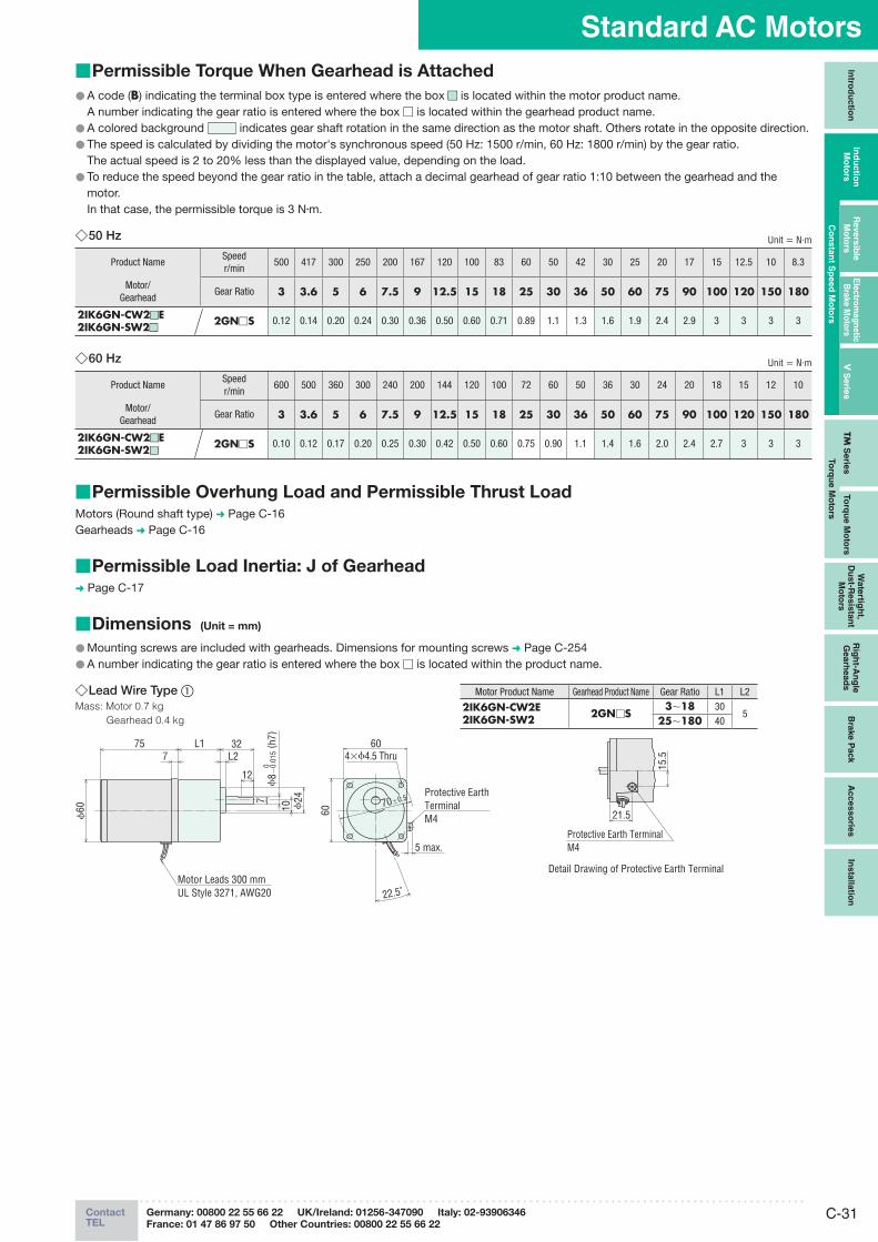
Permissible Torque When Gearhead is Attached ■
A code ( ● B) indicating the terminal box type is entered where the box ■■ is located within the motor product name. A number indicating the gear ratio is entered where the box □ is located within the gearhead product name.
A colored background ● indicates gear shaft rotation in the same direction as the motor shaft. Others rotate in the opposite direction.The speed is calculated by dividing the motor's synchronous speed (50 Hz: 1500 r/min, 60 Hz: 1800 r/min) by the gear ratio. ●
The actual speed is 2 to 20% less than the displayed value, depending on the load.To reduce the speed beyond the gear ratio in the table, attach a decimal gearhead of gear ratio 1:10 between the gearhead and the ●motor.
In that case, the permissible torque is 3 N·m.
50 Hz ◇ Unit = N·m
Product NameSpeedr/min
500 417 300 250 200 167 120 100 83 60 50 42 30 25 20 17 15 12.5 10 8.3
Motor/Gearhead
Gear Ratio 3 3.6 5 6 7.5 9 12.5 15 18 25 30 36 50 60 75 90 100 120 150 180
2IK6GN-CW2 ■ ■E2IK6GN-SW2■■
2GN□S 0.12 0.14 0.20 0.24 0.30 0.36 0.50 0.60 0.71 0.89 1.1 1.3 1.6 1.9 2.4 2.9 3 3 3 3
Permissible Overhung Load and Permissible Thrust Load ■Motors (Round shaft type) ➜ Page C-16Gearheads ➜ Page C-16
Permissible Load Inertia: J of Gearhead ■➜ Page C-17
Dimensions ■ (Unit = mm)
Mounting screws are included with gearheads. Dimensions for mounting screws ● ➜ Page C-254A number indicating the gear ratio is entered where the box ● □ is located within the product name.
Lead Wire Type ◇ ①Mass: Motor 0.7 kg
Gearhead 0.4 kg
75 L1 32L2
10
12
ϕ24
60
ϕ60
7
7 70±0.5
22.5˚
60
ϕ8 −
0.01
5 ( h
7)0
5 max.
4×ϕ4.5 Thru
Motor Leads 300 mmUL Style 3271, AWG20
Protective Earth TerminalM4
Motor Product Name Gearhead Product Name Gear Ratio L1 L2
2IK6GN-CW2E2IK6GN-SW2 2GN□S
3∼18 305
25∼180 40
15.5
21.5
Detail Drawing of Protective Earth Terminal
Protective Earth TerminalM4
60 Hz ◇ Unit = N·m
Product NameSpeedr/min
600 500 360 300 240 200 144 120 100 72 60 50 36 30 24 20 18 15 12 10
Motor/Gearhead
Gear Ratio 3 3.6 5 6 7.5 9 12.5 15 18 25 30 36 50 60 75 90 100 120 150 180
2IK6GN-CW2 ■ ■E2IK6GN-SW2 ■ ■
2GN□S 0.10 0.12 0.17 0.20 0.25 0.30 0.42 0.50 0.60 0.75 0.90 1.1 1.4 1.6 2.0 2.4 2.7 3 3 3
ORIENTAL MOTOR GENERAL CATALOGUE 2012/2013
C-32 Page Features C-20 / System Configuration C-23 / Product Line C-30 / Specifications C-30
Dimensions C-31 / Connection Diagrams C-29
Induction Motors
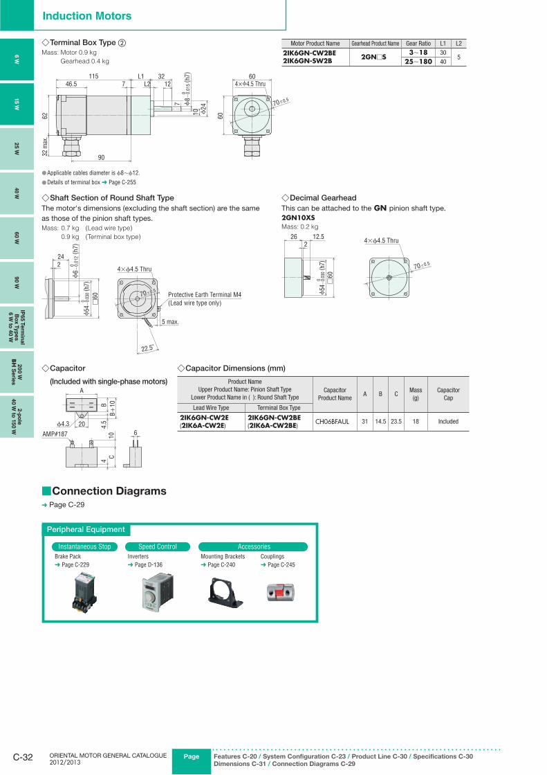
Capacitor ◇
(Included with single-phase motors)
ϕ4.3 20
A
CB+
10B4.
54
10 6AMP#187
Capacitor Dimensions (mm) ◇
Product NameUpper Product Name: Pinion Shaft Type
Lower Product Name in ( ): Round Shaft TypeCapacitor
Product NameA B C
Mass(g)
CapacitorCap
Lead Wire Type Terminal Box Type
2IK6GN-CW2E(2IK6A-CW2E)
2IK6GN-CW2BE(2IK6A-CW2BE)
CH06BFAUL 31 14.5 23.5 18 Included
Connection Diagrams ■➜ Page C-29
Peripheral Equipment
Instantaneous Stop Speed Control AccessoriesBrake Pack➜ Page C-229
Inverters➜ Page D-136
Mounting Brackets➜ Page C-240
Couplings➜ Page C-245
Terminal Box Type ◇ ②Mass: Motor 0.9 kg
Gearhead 0.4 kg
62
46.5
90
1157
32 m
ax.
L1L2 12
ϕ24
32
10
7
4×ϕ4.5 Thru
70±0.5
ϕ8−
0.01
5 ( h
7)0
60
60
Applicable cables diameter is ● ϕ8∼ϕ12.
Details of terminal box ● ➜ Page C-255
Motor Product Name Gearhead Product Name Gear Ratio L1 L2
2IK6GN-CW2BE2IK6GN-SW2B 2GN□S
3∼18 305
25∼180 40
Shaft Section of Round Shaft Type ◇The motor's dimensions (excluding the shaft section) are the same as those of the pinion shaft types.Mass: 0.7 kg (Lead wire type)
0.9 kg (Terminal box type)
224
22.5˚
70±0.5
□60
ϕ54
−0.
030
( h7)
0
ϕ6 −
0.01
2 ( h
7)0
5 max.
4×ϕ4.5 Thru
Protective Earth Terminal M4 (Lead wire type only)
Decimal Gearhead ◇This can be attached to the GN pinion shaft type.2GN10XSMass: 0.2 kg
26 12.52
70±0.5
□60
ϕ54
−0.
030
( h7)
0
4×ϕ4.5 Thru
6 W
15 W
25 W
40 W
60 W
90 W
IP65 T
erm
inal
Bo
x T
yp
es
6 W
to 4
0 W
20
0 W
BH
Serie
s2-p
ole
40 W
to 1
50 W
C-33ContactTEL
Germany: 00800 22 55 66 22 UK/Ireland: 01256-347090 Italy: 02-93906346
France: 01 47 86 97 50 Other Countries: 00800 22 55 66 22
Standard AC MotorsIn
trod
uctio
nIn
du
ctio
n
Mo
tor s
Revers
ible
M
oto
rsE
lectro
mag
netic
B
rake M
oto
rsV
Serie
sTM
Serie
sTo
rqu
e M
oto
rs
Wate
rtigh
t, D
ust-R
esis
tan
t M
oto
rs
Rig
ht-A
ng
le
Gearh
ead
sB
rake P
ack
Accesso
ries
Insta
llatio
n
Co
nsta
nt S
peed
Mo
tors
To
rqu
e M
oto
rs
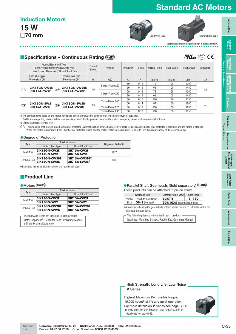
Induction Motors
15 W□70 mm
Gearhead shown in the photograph is sold separately.
Specifications – Continuous Rating ■
Product Name and TypeUpper Product Name: Pinion Shaft Type
Lower Product Name in ( ): Round Shaft Type
Output Power
Voltage Frequency Current Starting Torque Rated Torque Rated Speed Capacitor
Lead Wire TypeDimensions ①
Terminal Box TypeDimensions ② W VAC Hz A mN·m mN·m r/min μF
3IK15GN-CW2E(3IK15A-CW2E)
3IK15GN-CW2BE(3IK15A-CW2BE)
15Single-Phase 220
50 0.19 70 125 1200
1.060 0.16 65 105 1450
Single-Phase 23050 0.19 75 125 120060 0.16 65 105 1450
3IK15GN-SW2(3IK15A-SW2)
3IK15GN-SW2B(3IK15A-SW2B)
15Three-Phase 200
50 0.17 110 110 1350
−60 0.14 85 100 1600
Three-Phase 220 60 0.15 100 100 1650Three-Phase 230 60 0.16 100 100 1650
The product name listed on the motor nameplate does not include the code ( ● E) that indicates the type of capacitor.Certification regarding various safety standards is acquired for the product name on the motor nameplate, please visit www.orientalmotor.eu.Safety standards ● ➜ Page H-2
: This indicates that there is a built-in thermal protector (automatic return type). If a motor overheats for any reason, the thermal protector is activated and the motor is stopped. When the motor temperature drops, the thermal protector closes and the motor restarts automatically. Be sure to turn the power supply off before inspecting.
Degree of Protection ●
TypeProduct Name
Degree of ProtectionPinion Shaft Type Round Shaft Type
Lead Wire 3IK15GN-CW2E3IK15GN-SW2
3IK15A-CW2E3IK15A-SW2 IP20
Terminal Box 3IK15GN-CW2BE3IK15GN-SW2B
3IK15A-CW2BE✽
3IK15A-SW2B✽ IP65
Excluding the installation surface of the round shaft type. ✽
Product Line■
Motors ●
TypeProduct Name
Pinion Shaft Type Round Shaft Type
Lead Wire3IK15GN-CW2E 3IK15A-CW2E3IK15GN-SW2 3IK15A-SW2
Terminal Box3IK15GN-CW2BE 3IK15A-CW2BE3IK15GN-SW2B 3IK15A-SW2B
Parallel Shaft Gearheads (Sold separately) ● These products can be attached to pinion shafts.
Gearhead Type Gearhead Product Name Gear Ratio
Parallel Shaft
Long Life, Low Noise GN-S Gearhead
3GN□S 3∼1803GN10XS (Decimal gearhead)
A number indicating the gear ratio is entered where the box ● □ is located within the gearhead product name.
Terminal Box TypeLead Wire Type
Highest Maximum Permissible torque, 10,000 hours✽ of life and quiet operation. For more details on V Series see page C-149.
For the rated life time definition, refer to "Service Life of ✽
Gearheads" on page G-35.
High Strength, Long Life, Low NoiseV Series
The following items are included in each product.Motor, Capacitor✽, Capacitor Cap✽, Operating Manual✽Single-Phase Motors only
The following items are included in each product.Gearhead, Mounting Screws, Parallel Key, Operating Manual
ORIENTAL MOTOR GENERAL CATALOGUE 2012/2013
C-34
Induction Motors
Page Features C-20 / System Configuration C-23 / Product Line C-33 / Specifications C-33
Dimensions C-34 / Connection Diagrams C-29
6 W
15 W
25 W
40 W
60 W
90 W
IP65 T
erm
inal
Bo
x T
yp
es
6 W
to 4
0 W
20
0 W
BH
Serie
s2-p
ole
40 W
to 1
50 W
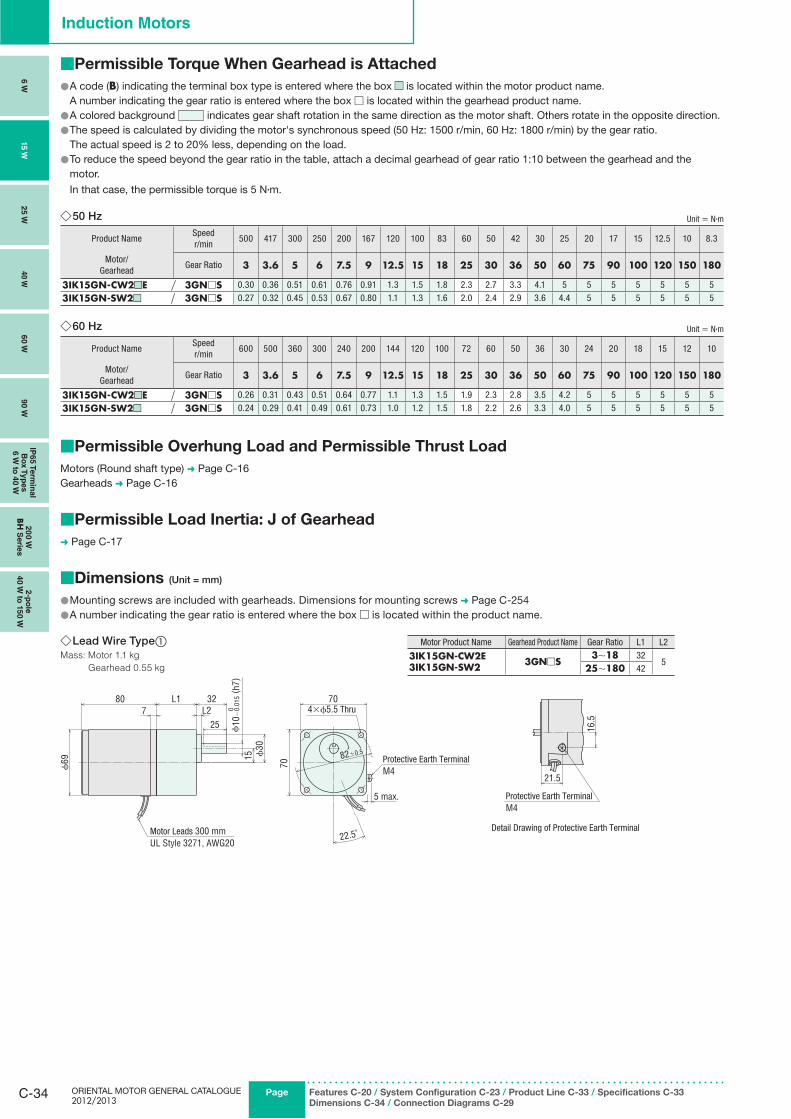
Lead Wire Type ◇ ①Mass: Motor 1.1 kg
Gearhead 0.55 kg
ϕ69
807
L1 32L2
25
15 ϕ30
82±0.5
70
70
22.5˚
ϕ10
−0.
015
( h7)
0
5 max.
4×ϕ5.5 Thru
Protective Earth Terminal M4
Motor Leads 300 mm UL Style 3271, AWG20
Motor Product Name Gearhead Product Name Gear Ratio L1 L2
3IK15GN-CW2E3IK15GN-SW2 3GN□S
3∼18 325
25∼180 42
16.5
21.5
Detail Drawing of Protective Earth Terminal
Protective Earth TerminalM4
Permissible Torque When Gearhead is Attached■
A code ( ● B) indicating the terminal box type is entered where the box ■■ is located within the motor product name. A number indicating the gear ratio is entered where the box □ is located within the gearhead product name.
A colored background ● indicates gear shaft rotation in the same direction as the motor shaft. Others rotate in the opposite direction.The speed is calculated by dividing the motor's synchronous speed (50 Hz: 1500 r/min, 60 Hz: 1800 r/min) by the gear ratio. ●
The actual speed is 2 to 20% less, depending on the load.To reduce the speed beyond the gear ratio in the table, attach a decimal gearhead of gear ratio 1:10 between the gearhead and the ●motor.
In that case, the permissible torque is 5 N·m.
50 Hz ◇ Unit = N·m
Product NameSpeedr/min
500 417 300 250 200 167 120 100 83 60 50 42 30 25 20 17 15 12.5 10 8.3
Motor/Gearhead
Gear Ratio 3 3.6 5 6 7.5 9 12.5 15 18 25 30 36 50 60 75 90 100 120 150 180
3IK15GN-CW2■■E 3GN□S 0.30 0.36 0.51 0.61 0.76 0.91 1.3 1.5 1.8 2.3 2.7 3.3 4.1 5 5 5 5 5 5 5
3IK15GN-SW2■■ 3GN□S 0.27 0.32 0.45 0.53 0.67 0.80 1.1 1.3 1.6 2.0 2.4 2.9 3.6 4.4 5 5 5 5 5 5
60 Hz ◇ Unit = N·m
Product NameSpeedr/min
600 500 360 300 240 200 144 120 100 72 60 50 36 30 24 20 18 15 12 10
Motor/Gearhead
Gear Ratio 3 3.6 5 6 7.5 9 12.5 15 18 25 30 36 50 60 75 90 100 120 150 180
3IK15GN-CW2■■E 3GN□S 0.26 0.31 0.43 0.51 0.64 0.77 1.1 1.3 1.5 1.9 2.3 2.8 3.5 4.2 5 5 5 5 5 5
3IK15GN-SW2■■ 3GN□S 0.24 0.29 0.41 0.49 0.61 0.73 1.0 1.2 1.5 1.8 2.2 2.6 3.3 4.0 5 5 5 5 5 5
Permissible Overhung Load and Permissible Thrust Load■
Motors (Round shaft type) ➜ Page C-16Gearheads ➜ Page C-16
Permissible Load Inertia: J of Gearhead■
➜ Page C-17
Dimensions■ (Unit = mm)
Mounting screws are included with gearheads. Dimensions for mounting screws ● ➜ Page C-254A number indicating the gear ratio is entered where the box ● □ is located within the product name.
C-35ContactTEL
Germany: 00800 22 55 66 22 UK/Ireland: 01256-347090 Italy: 02-93906346
France: 01 47 86 97 50 Other Countries: 00800 22 55 66 22
Standard AC MotorsIn
trod
uctio
nIn
du
ctio
n
Mo
tor s
Revers
ible
M
oto
rsE
lectro
mag
netic
B
rake M
oto
rsV
Serie
sTM
Serie
sTo
rqu
e M
oto
rs
Wate
rtigh
t, D
ust-R
esis
tan
t M
oto
rs
Rig
ht-A
ng
le
Gearh
ead
sB
rake P
ack
Accesso
ries
Insta
llatio
n
Co
nsta
nt S
peed
Mo
tors
To
rqu
e M
oto
rs
ϕ4.3 20
A
CB+
10B4.
54
10 6AMP#187
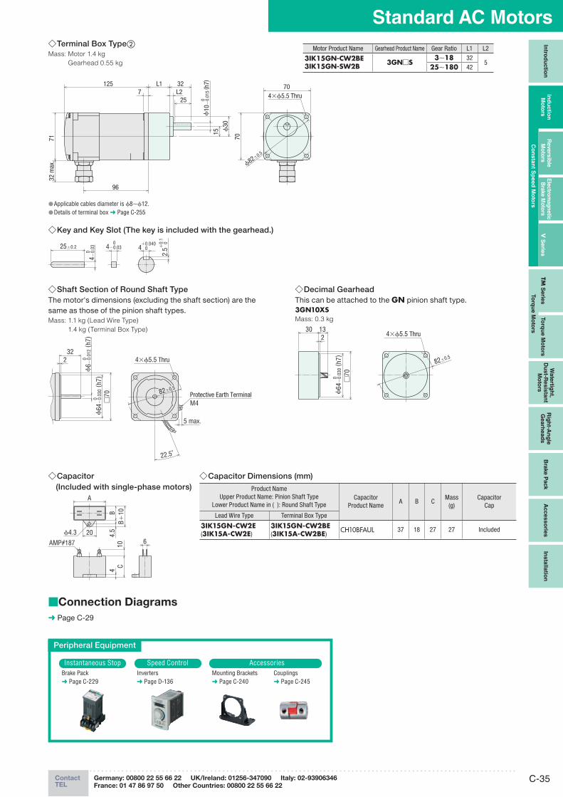
Capacitor Dimensions (mm) ◇Product Name
Upper Product Name: Pinion Shaft TypeLower Product Name in ( ): Round Shaft Type
CapacitorProduct Name
A B CMass
(g)Capacitor
Cap
Lead Wire Type Terminal Box Type
3IK15GN-CW2E(3IK15A-CW2E)
3IK15GN-CW2BE(3IK15A-CW2BE)
CH10BFAUL 37 18 27 27 Included
Capacitor ◇ (Included with single-phase motors)
Connection Diagrams■
➜ Page C-29
Peripheral Equipment
Instantaneous Stop Speed Control AccessoriesBrake Pack➜ Page C-229
Inverters➜ Page D-136
Mounting Brackets➜ Page C-240
Couplings➜ Page C-245
Key and Key Slot (The key is included with the gearhead.) ◇
25±0.2 4 0 +0.040
2.5
0 +0.
1
4−0.
03 0
4−0.03 0
Shaft Section of Round Shaft Type ◇The motor's dimensions (excluding the shaft section) are the same as those of the pinion shaft types.Mass: 1.1 kg (Lead Wire Type)
1.4 kg (Terminal Box Type)
232
82±0.5
□70
22.5˚
ϕ64
−0.
030
( h7)
0ϕ
6 −0.
012
( h7)
0
5 max.
4×ϕ5.5 Thru
Protective Earth Terminal M4
Decimal Gearhead ◇This can be attached to the GN pinion shaft type.3GN10XSMass: 0.3 kg
30 132
82±0.5
ϕ64
−0.
030
( h7)
0 □70
4×ϕ5.5 Thru
Terminal Box Type ◇ ②Mass: Motor 1.4 kg
Gearhead 0.55 kg
96
32L2
25
1257
7132
max
.
L1
15 ϕ30
ϕ10
−0.
015
( h7)
0
ϕ82±0.5
4×ϕ5.5 Thru
70
70
Motor Product Name Gearhead Product Name Gear Ratio L1 L2
3IK15GN-CW2BE3IK15GN-SW2B 3GN□S
3∼18 325
25∼180 42
Applicable cables diameter is ● ϕ8∼ϕ12.Details of terminal box ● ➜ Page C-255
ORIENTAL MOTOR GENERAL CATALOGUE 2012/2013
C-36 Page Features C-20 / System Configuration C-23 / Product Line C-36 / Specifications C-36
Dimensions C-37 / Connection Diagrams C-29
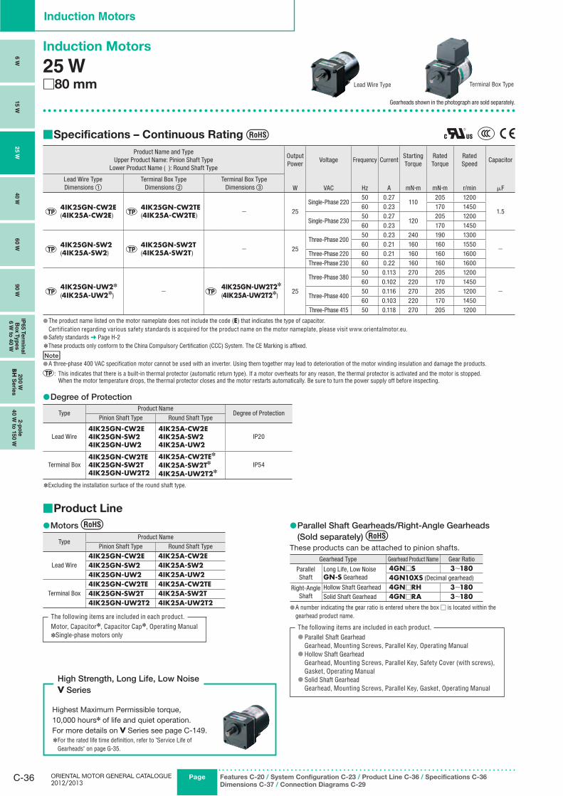
Induction Motors
Induction Motors
25 W□80 mm
Gearheads shown in the photograph are sold separately.
Specifications – Continuous Rating ■
Product Name and TypeUpper Product Name: Pinion Shaft Type
Lower Product Name ( ): Round Shaft Type
Output Power
Voltage Frequency CurrentStartingTorque
RatedTorque
Rated Speed
Capacitor
Lead Wire TypeDimensions ①
Terminal Box TypeDimensions ②
Terminal Box TypeDimensions ③ W VAC Hz A mN·m mN·m r/min μF
4IK25GN-CW2E(4IK25A-CW2E)
4IK25GN-CW2TE(4IK25A-CW2TE)
− 25Single-Phase 220
50 0.27 110
205 1200
1.560 0.23 170 1450
Single-Phase 23050 0.27
120205 1200
60 0.23 170 1450
4IK25GN-SW2(4IK25A-SW2)
4IK25GN-SW2T(4IK25A-SW2T)
− 25Three-Phase 200
50 0.23 240 190 1300
−60 0.21 160 160 1550
Three-Phase 220 60 0.21 160 160 1600Three-Phase 230 60 0.22 160 160 1600
4IK25GN-UW2✽
(4IK25A-UW2✽)−
4IK25GN-UW2T2✽
(4IK25A-UW2T2✽)25
Three-Phase 38050 0.113 270 205 1200
−60 0.102 220 170 1450
Three-Phase 40050 0.116 270 205 120060 0.103 220 170 1450
Three-Phase 415 50 0.118 270 205 1200
The product name listed on the motor nameplate does not include the code ( ● E) that indicates the type of capacitor.Certification regarding various safety standards is acquired for the product name on the motor nameplate, please visit www.orientalmotor.eu.Safety standards ● ➜ Page H-2These products only conform to the China Compulsory Certification (CCC) System. The CE Marking is affixed. ✽
NoteA three-phase 400 VAC specification motor cannot be used with an inverter. Using them together may lead to deterioration of the motor winding insulation and damage the products. ●
: This indicates that there is a built-in thermal protector (automatic return type). If a motor overheats for any reason, the thermal protector is activated and the motor is stopped. When the motor temperature drops, the thermal protector closes and the motor restarts automatically. Be sure to turn the power supply off before inspecting.
Degree of Protection ●
TypeProduct Name
Degree of ProtectionPinion Shaft Type Round Shaft Type
Lead Wire4IK25GN-CW2E4IK25GN-SW24IK25GN-UW2
4IK25A-CW2E4IK25A-SW24IK25A-UW2
IP20
Terminal Box4IK25GN-CW2TE4IK25GN-SW2T4IK25GN-UW2T2
4IK25A-CW2TE✽
4IK25A-SW2T✽
4IK25A-UW2T2✽IP54
Excluding the installation surface of the round shaft type. ✽
Terminal Box TypeLead Wire Type
Product Line ■
Motors ●
TypeProduct Name
Pinion Shaft Type Round Shaft Type
Lead Wire4IK25GN-CW2E 4IK25A-CW2E4IK25GN-SW2 4IK25A-SW24IK25GN-UW2 4IK25A-UW2
Terminal Box4IK25GN-CW2TE 4IK25A-CW2TE4IK25GN-SW2T 4IK25A-SW2T4IK25GN-UW2T2 4IK25A-UW2T2
The following items are included in each product.Motor, Capacitor✽, Capacitor Cap✽, Operating Manual
Single-phase motors only ✽
Parallel Shaft Gearheads/Right-Angle Gearheads ●(Sold separately)
These products can be attached to pinion shafts.
Gearhead Type Gearhead Product Name Gear Ratio
Parallel Shaft
Long Life, Low NoiseGN-S Gearhead
4GN□S 3∼1804GN10XS (Decimal gearhead)
Right-Angle Shaft
Hollow Shaft Gearhead 4GN□RH 3∼180Solid Shaft Gearhead 4GN□RA 3∼180
A number indicating the gear ratio is entered where the box ● □ is located within the gearhead product name.
The following items are included in each product.Parallel Shaft Gearhead ●Gearhead, Mounting Screws, Parallel Key, Operating ManualHollow Shaft Gearhead ●Gearhead, Mounting Screws, Parallel Key, Safety Cover (with screws),Gasket, Operating ManualSolid Shaft Gearhead ●Gearhead, Mounting Screws, Parallel Key, Gasket, Operating Manual
Highest Maximum Permissible torque, 10,000 hours✽ of life and quiet operation. For more details on V Series see page C-149.✽
For the rated life time definition, refer to "Service Life of Gearheads" on page G-35.
High Strength, Long Life, Low NoiseV Series
6 W
15 W
25 W
40 W
60 W
90 W
IP65 T
erm
inal
Bo
x T
yp
es
6 W
to 4
0 W
20
0 W
BH
Serie
s2-p
ole
40 W
to 1
50 W
C-37ContactTEL
Germany: 00800 22 55 66 22 UK/Ireland: 01256-347090 Italy: 02-93906346
France: 01 47 86 97 50 Other Countries: 00800 22 55 66 22
Standard AC MotorsIn
trod
uctio
nIn
du
ctio
n
Mo
t ors
Revers
ible
M
oto
rsE
lectro
mag
netic
B
rake M
oto
rsV
Serie
sTM
Serie
sTo
rqu
e M
oto
rs
Wate
rtigh
t, D
ust-R
esis
tan
t M
oto
rs
Rig
ht-A
ng
le
Gearh
ead
sB
rake P
ack
Acc
es
so
ries
Insta
llatio
n
Co
nsta
nt S
peed
Mo
tors
To
rqu
e M
oto
rs
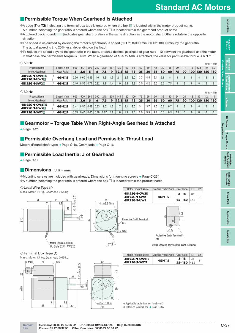
Permissible Torque When Gearhead is Attached ■
A code ( ● T or T2) indicating the terminal box type is entered where the box ■■ is located within the motor product name. A number indicating the gear ratio is entered where the box □ is located within the gearhead product name.
A colored background ● indicates gear shaft rotation in the same direction as the motor shaft. Others rotate in the opposite direction.The speed is calculated by dividing the motor's synchronous speed (50 Hz: 1500 r/min, 60 Hz: 1800 r/min) by the gear ratio. ●
The actual speed is 2 to 20% less, depending on the load.To reduce the speed beyond the gear ratio in the table, attach a decimal gearhead of gear ratio 1:10 between the gearhead and the motor. ●
In that case, the permissible torque is 8 N·m. When a gearhead of 1/25 to 1/36 is attached, the value for permissible torque is 6 N·m.
50 Hz ◇ Unit = N·mProduct Name Speed r/min 500 417 300 250 200 167 120 100 83 60 50 42 30 25 20 17 15 12.5 10 8.3
Motor/Gearhead Gear Ratio 3 3.6 5 6 7.5 9 12.5 15 18 25 30 36 50 60 75 90 100 120 150 1804IK25GN-CW2 ■ ■E4IK25GN-UW2 ■ ■
4GN□S 0.50 0.60 0.83 1.0 1.2 1.5 2.1 2.5 3.0 3.7 4.5 5.4 6.8 8 8 8 8 8 8 8
4IK25GN-SW2 ■ ■ 4GN□S 0.46 0.55 0.77 0.92 1.2 1.4 1.9 2.3 2.8 3.5 4.2 5.0 6.3 7.5 8 8 8 8 8 8
60 Hz ◇ Unit = N·mProduct Name Speed r/min 600 500 360 300 240 200 144 120 100 72 60 50 36 30 24 20 18 15 12 10
Motor/Gearhead Gear Ratio 3 3.6 5 6 7.5 9 12.5 15 18 25 30 36 50 60 75 90 100 120 150 1804IK25GN-CW2 ■ ■E4IK25GN-UW2 ■ ■
4GN□S 0.41 0.50 0.69 0.83 1.0 1.2 1.7 2.1 2.5 3.1 3.7 4.5 5.6 6.7 8 8 8 8 8 8
4IK25GN-SW2 ■ ■ 4GN□S 0.39 0.47 0.65 0.78 0.97 1.2 1.6 1.9 2.3 2.9 3.5 4.2 5.3 6.3 7.9 8 8 8 8 8
Gearmotor – Torque Table When Right-Angle Gearhead is Attached ■➜ Page C-216
Permissible Overhung Load and Permissible Thrust Load ■Motors (Round shaft type) ➜ Page C-16, Gearheads ➜ Page C-16
Permissible Load Inertia: J of Gearhead ■➜ Page C-17
Dimensions ■ (Unit = mm)
Mounting screws are included with gearheads. Dimensions for mounting screws ● ➜ Page C-254A number indicating the gear ratio is entered where the box ● □ is located within the product name.
Lead Wire Type ◇ ①Mass: Motor 1.5 kg, Gearhead 0.65 kg
ϕ79
L185 32L2
94±0.5
7
25
ϕ34
15
80
80
22.5˚
ϕ10
−0.
015
( h7)
0
5 max.
4×ϕ5.5 Thru
Protective Earth TerminalM4
Motor Leads 300 mmUL Style 3271, AWG20
Motor Product Name Gearhead Product Name Gear Ratio L1 L2
4IK25GN-CW2E4IK25GN-SW24IK25GN-UW2
4GN□S3∼18 32
625∼180 42.5
16.5
21.5
Detail Drawing of Protective Earth Terminal
Protective Earth TerminalM4
Terminal Box Type ◇ ②Mass: Motor 1.7 kg, Gearhead 0.65 kg
28 max. 75
ϕ79
5.5
85 L1L2
327
25
ϕ34
15
80
62
43
94±0.5
25
80
ϕ10
−0.
015
( h7)
0
4×ϕ5.5 Thru Applicable cable diameter is ● ϕ6∼ϕ12.Details of terminal box ● ➜ Page C-255
Motor Product Name Gearhead Product Name Gear Ratio L1 L2
4IK25GN-CW2TE4IK25GN-SW2T 4GN□S
3∼18 326
25∼180 42.5
ORIENTAL MOTOR GENERAL CATALOGUE 2012/2013
C-38 Page Features C-20 / System Configuration C-23 / Product Line C-36 / Specifications C-36
Dimensions C-37 / Connection Diagrams C-29
Induction Motors
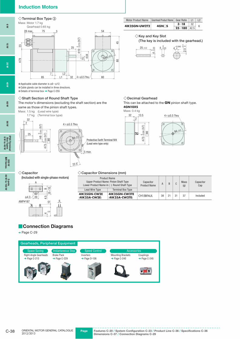
Shaft Section of Round Shaft Type ◇The motor's dimensions (excluding the shaft section) are the same as those of the pinion shaft types.Mass: 1.5 kg (Lead wire type)
1.7 kg (Terminal box type)
232
94±0.525
7
□80
22.5˚
ϕ73
−0.
030
( h7)
0
ϕ8 −
0.01
5 ( h
7)0
5 max.
4×ϕ5.5 Thru
Protective Earth Terminal M4 (Lead wire type only)
Decimal Gearhead ◇This can be attached to the GN pinion shaft type.4GN10XSMass: 0.4 kg
32 13.52
□80 94±0.5
ϕ73
−0.
030
( h7)
0
4×ϕ5.5 Thru
Terminal Box Type ◇ ③Mass: Motor 1.7 kg
Gearhead 0.65 kg
45
80
80
54
15 ϕ34
ϕ10
−0.
015
( h7)
025
L1857 L2
32
ϕ79
75
23
3
ϕ94±0.5
28 max.
4×ϕ5.5 Thru
Applicable cable diameter is ● ϕ6∼ϕ12.Cable glands can be installed in three directions. ●Details of terminal box ● ➜ Page C-255
Motor Product Name Gearhead Product Name Gear Ratio L1 L2
4IK25GN-UW2T2 4GN□S3∼18 32
625∼180 42.5
Key and Key Slot ◇(The key is included with the gearhead.)
25±0.2 4 0 +0.040
2.5
0 +0.
1
4−0.
03 0
4−0.03 0
Capacitor ◇ (Included with single-phase motors)
ϕ4.3 20
A
CB+
10B4.
54
10 6AMP#187
Capacitor Dimensions (mm) ◇Product Name
Upper Product Name: Pinion Shaft TypeLower Product Name in ( ): Round Shaft Type
CapacitorProduct Name
A B CMass
(g)Capacitor
Cap
Lead Wire Type Terminal Box Type
4IK25GN-CW2E(4IK25A-CW2E)
4IK25GN-CW2TE(4IK25A-CW2TE)
CH15BFAUL 38 21 31 37 Included
Connection Diagrams ■➜ Page C-29
Gearheads, Peripheral Equipment
Space Saving Instantaneous Stop Speed Control AccessoriesRight-Angle Gearheads➜ Page C-213
Brake Pack➜ Page C-229
Inverters➜ Page D-136
Mounting Brackets➜ Page C-240
Couplings➜ Page C-245
6 W
15 W
25 W
40 W
60 W
90 W
IP65 T
erm
inal
Bo
x T
yp
es
6 W
to 4
0 W
20
0 W
BH
Serie
s2-p
ole
40 W
to 1
50 W
C-39ContactTEL
Germany: 00800 22 55 66 22 UK/Ireland: 01256-347090 Italy: 02-93906346
France: 01 47 86 97 50 Other Countries: 00800 22 55 66 22
Standard AC MotorsIn
trod
uctio
nIn
du
ctio
n
Mo
t ors
Revers
ible
M
oto
rsE
lectro
mag
netic
B
rake M
oto
rsV
Serie
sTM
Serie
sTo
rqu
e M
oto
rs
Wate
rtigh
t, D
ust-R
esis
tan
t M
oto
rs
Rig
ht-A
ng
le
Gearh
ead
sB
rake P
ack
Acc
es
so
ries
Insta
llatio
n
Co
nsta
nt S
peed
Mo
tors
To
rqu
e M
oto
rs
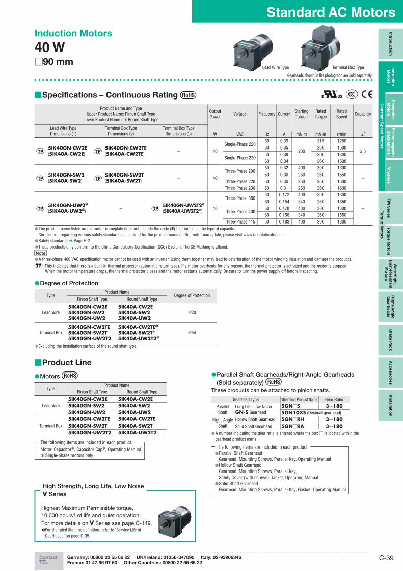
Product Line ■
Motors ●
TypeProduct Name
Pinion Shaft Type Round Shaft Type
Lead Wire5IK40GN-CW2E 5IK40A-CW2E5IK40GN-SW2 5IK40A-SW25IK40GN-UW2 5IK40A-UW2
Terminal Box5IK40GN-CW2TE 5IK40A-CW2TE5IK40GN-SW2T 5IK40A-SW2T5IK40GN-UW2T2 5IK40A-UW2T2
Motor, Capacitor✽, Capacitor Cap✽, Operating ManualSingle-phase motors only ✽
The following items are included in each product.
Parallel Shaft Gearheads/Right-Angle Gearheads ●(Sold separately)
These products can be attached to pinion shafts.
Gearhead Type Gearhead Product Name Gear Ratio
Parallel Shaft
Long Life, Low NoiseGN-S Gearhead
5GN□S 3∼1805GN10XS (Decimal gearhead)
Right-Angle Shaft
Hollow Shaft Gearhead 5GN□RH 3∼180Solid Shaft Gearhead 5GN□RA 3∼180
A number indicating the gear ratio is entered where the box ● □ is located within the gearhead product name.
Induction Motors
40 W □90 mm
Specifications – Continuous Rating ■
Product Name and TypeUpper Product Name: Pinion Shaft Type
Lower Product Name ( ): Round Shaft Type
Output Power
Voltage Frequency CurrentStartingTorque
RatedTorque
RatedSpeed
Capacitor
Lead Wire TypeDimensions ①
Terminal Box TypeDimensions ②
Terminal Box TypeDimensions ③ W VAC Hz A mN·m mN·m r/min μF
5IK40GN-CW2E(5IK40A-CW2E)
5IK40GN-CW2TE(5IK40A-CW2TE)
− 40Single-Phase 220
50 0.39
200
315 1250
2.360 0.35 260 1500
Single-Phase 23050 0.39 300 130060 0.34 260 1500
5IK40GN-SW2(5IK40A-SW2)
5IK40GN-SW2T(5IK40A-SW2T)
− 40Three-Phase 200
50 0.32 400 300 1300
−60 0.30 260 260 1550
Three-Phase 220 60 0.30 260 260 1600Three-Phase 230 60 0.31 260 260 1600
5IK40GN-UW2✽
(5IK40A-UW2✽)−
5IK40GN-UW2T2✽
(5IK40A-UW2T2✽)40
Three-Phase 38050 0.172 400 300 1300
−
60 0.154 340 260 1550
Three-Phase 40050 0.178 400 300 130060 0.156 340 260 1550
Three-Phase 415 50 0.183 400 300 1300The product name listed on the motor nameplate does not include the code ( ● E) that indicates the type of capacitor.Certification regarding various safety standards is acquired for the product name on the motor nameplate, please visit www.orientalmotor.eu.Safety standards ● ➜ Page H-2These products only conform to the China Compulsory Certification (CCC) System. The CE Marking is affixed. ✽
NoteA three-phase 400 VAC specification motor cannot be used with an inverter. Using them together may lead to deterioration of the motor winding insulation and damage the products. ●
: This indicates that there is a built-in thermal protector (automatic return type). If a motor overheats for any reason, the thermal protector is activated and the motor is stopped. When the motor temperature drops, the thermal protector closes and the motor restarts automatically. Be sure to turn the power supply off before inspecting.
Degree of Protection ●
TypeProduct Name
Degree of ProtectionPinion Shaft Type Round Shaft Type
Lead Wire5IK40GN-CW2E5IK40GN-SW25IK40GN-UW2
5IK40A-CW2E5IK40A-SW25IK40A-UW2
IP20
Terminal Box 5IK40GN-CW2TE5IK40GN-SW2T5IK40GN-UW2T2
5IK40A-CW2TE✽
5IK40A-SW2T✽
5IK40A-UW2T2✽IP54
Excluding the installation surface of the round shaft type. ✽
Gearheads shown in the photograph are sold separately.
Highest Maximum Permissible torque, 10,000 hours✽ of life and quiet operation. For more details on V Series see page C-149.
For the rated life time definition, refer to "Service Life of ✽
Gearheads" on page G-35.
High Strength, Long Life, Low NoiseV Series
Lead Wire Type Terminal Box Type
Parallel Shaft Gearhead ●Gearhead, Mounting Screws, Parallel Key, Operating ManualHollow Shaft Gearhead ●Gearhead, Mounting Screws, Parallel Key, Safety Cover (with screws),Gasket, Operating ManualSolid Shaft Gearhead ●Gearhead, Mounting Screws, Parallel Key, Gasket, Operating Manual
The following items are included in each product.
ORIENTAL MOTOR GENERAL CATALOGUE 2012/2013
C-40 Page Features C-20 / System Configuration C-23 / Product Line C-39 / Specifications C-39
Dimensions C-40 / Connection Diagrams C-29
Induction Motors
6 W
15 W
25 W
40 W
60 W
90 W
IP65 T
erm
inal
Bo
x T
yp
es
6 W
to 4
0 W
20
0 W
BH
Serie
s2-p
ole
40 W
to 1
50 W
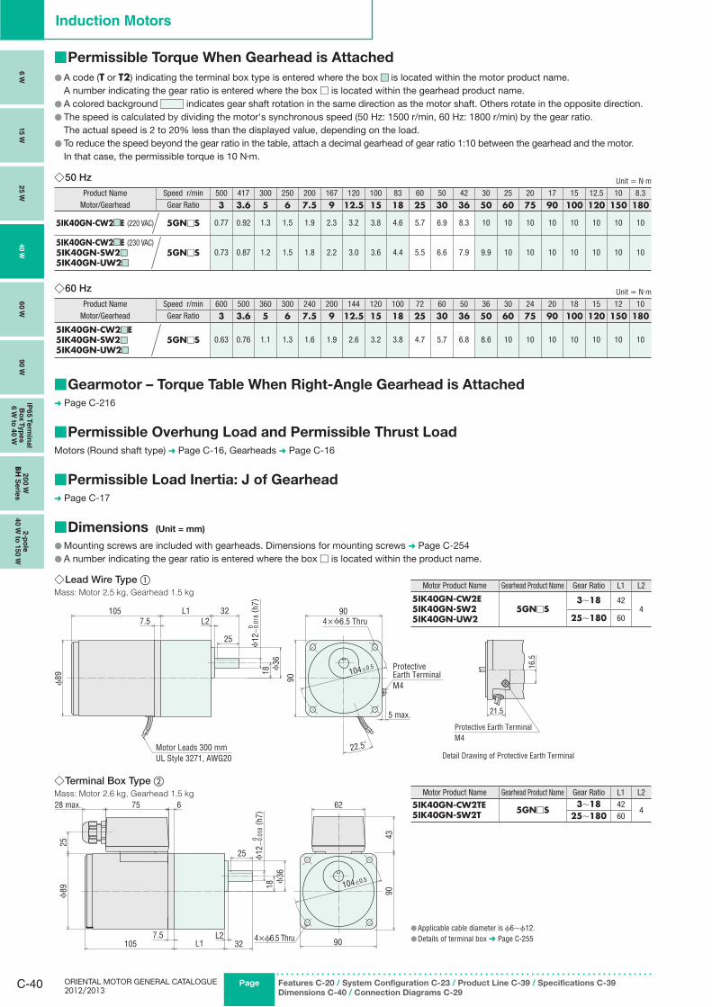
■ Permissible Torque When Gearhead is Attached
A code ( ● T or T2) indicating the terminal box type is entered where the box ■■ is located within the motor product name. A number indicating the gear ratio is entered where the box □ is located within the gearhead product name.
A colored background ● indicates gear shaft rotation in the same direction as the motor shaft. Others rotate in the opposite direction.The speed is calculated by dividing the motor's synchronous speed (50 Hz: 1500 r/min, 60 Hz: 1800 r/min) by the gear ratio. ●
The actual speed is 2 to 20% less than the displayed value, depending on the load.To reduce the speed beyond the gear ratio in the table, attach a decimal gearhead of gear ratio 1:10 between the gearhead and the motor. ●
In that case, the permissible torque is 10 N·m.
50 Hz ◇ Unit = N·m
Product Name Speed r/min 500 417 300 250 200 167 120 100 83 60 50 42 30 25 20 17 15 12.5 10 8.3Motor/Gearhead Gear Ratio 3 3.6 5 6 7.5 9 12.5 15 18 25 30 36 50 60 75 90 100 120 150 180
5IK40GN-CW2 ■■E (220 VAC) 5GN□S 0.77 0.92 1.3 1.5 1.9 2.3 3.2 3.8 4.6 5.7 6.9 8.3 10 10 10 10 10 10 10 10
5IK40GN-CW2 ■■E (230 VAC)5IK40GN-SW2 ■ ■
5IK40GN-UW2 ■ ■
5GN□S 0.73 0.87 1.2 1.5 1.8 2.2 3.0 3.6 4.4 5.5 6.6 7.9 9.9 10 10 10 10 10 10 10
60 Hz ◇ Unit = N·m
Product Name Speed r/min 600 500 360 300 240 200 144 120 100 72 60 50 36 30 24 20 18 15 12 10Motor/Gearhead Gear Ratio 3 3.6 5 6 7.5 9 12.5 15 18 25 30 36 50 60 75 90 100 120 150 180
5IK40GN-CW2 ■ ■E5IK40GN-SW2 ■ ■
5IK40GN-UW2 ■ ■
5GN□S 0.63 0.76 1.1 1.3 1.6 1.9 2.6 3.2 3.8 4.7 5.7 6.8 8.6 10 10 10 10 10 10 10
Gearmotor – Torque Table When Right-Angle Gearhead is Attached ■➜ Page C-216
Permissible Overhung Load and Permissible Thrust Load ■Motors (Round shaft type) ➜ Page C-16, Gearheads ➜ Page C-16
Permissible Load Inertia: J of Gearhead ■➜ Page C-17
Dimensions ■ (Unit = mm)
Mounting screws are included with gearheads. Dimensions for mounting screws ● ➜ Page C-254A number indicating the gear ratio is entered where the box ● □ is located within the product name.
Lead Wire Type ◇ ①Mass: Motor 2.5 kg, Gearhead 1.5 kg
Motor Product Name Gearhead Product Name Gear Ratio L1 L2
5IK40GN-CW2E5IK40GN-SW25IK40GN-UW2
5GN□S3∼18 42
425∼180 60
16.5
21.5
Detail Drawing of Protective Earth Terminal
Protective Earth TerminalM4
ϕ89
105 L1L2
327.5
18 ϕ36
25
90
104±0.5
90
22.5˚
ϕ12
−0.
018 (
h7)
0
5 max.
4×ϕ6.5 Thru
Motor Leads 300 mmUL Style 3271, AWG20
Protective Earth TerminalM4
Terminal Box Type ◇ ②Mass: Motor 2.6 kg, Gearhead 1.5 kg
28 max. 75 6
ϕ89
105 L1L2
327.5
18ϕ
36
62
90
104±0.5
25
25
4390
ϕ12
−0.
018
( h7)
0
4×ϕ6.5 ThruApplicable cable diameter is ● ϕ6∼ϕ12.Details of terminal box ● ➜ Page C-255
Motor Product Name Gearhead Product Name Gear Ratio L1 L2
5IK40GN-CW2TE5IK40GN-SW2T 5GN□S
3∼18 424
25∼180 60
C-41ContactTEL
Germany: 00800 22 55 66 22 UK/Ireland: 01256-347090 Italy: 02-93906346
France: 01 47 86 97 50 Other Countries: 00800 22 55 66 22
Standard AC MotorsIn
trod
uctio
nIn
du
ctio
n
Mo
t ors
Revers
ible
M
oto
rsE
lectro
mag
netic
B
rake M
oto
rsV
Serie
sTM
Serie
sTo
rqu
e M
oto
rs
Wate
rtigh
t, D
ust-R
esis
tan
t M
oto
rs
Rig
ht-A
ng
le
Gearh
ead
sB
rake P
ack
Acc
es
so
ries
Insta
llatio
n
Co
nsta
nt S
peed
Mo
tors
To
rqu
e M
oto
rs
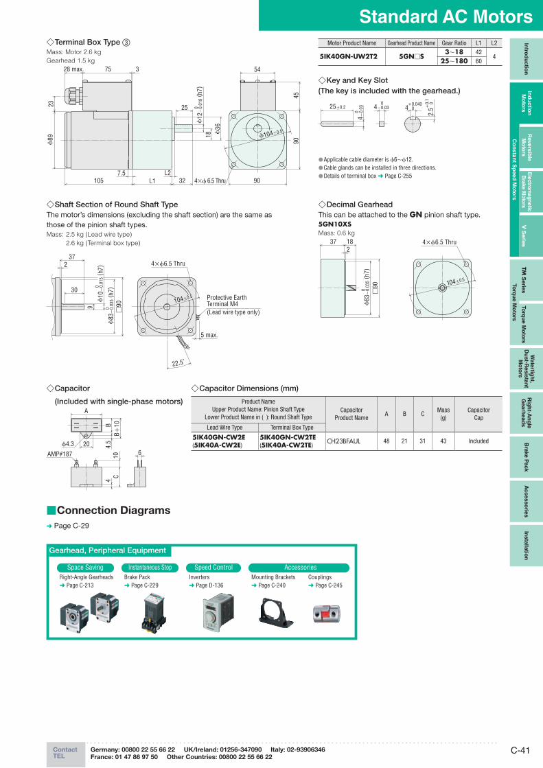
Terminal Box Type ◇ ③Mass: Motor 2.6 kg
Gearhead 1.5 kg
23
375
ϕ89
105 L1L2
327.5
4590
54
90
18 ϕ36
25
ϕ12
−0.
018 (
h7)
0
ϕ104±0.5
4×ϕ 6.5 Thru
28 max.
Motor Product Name Gearhead Product Name Gear Ratio L1 L2
5IK40GN-UW2T2 5GN□S3∼18 42
425∼180 60
Applicable cable diameter is ● ϕ6∼ϕ12.Cable glands can be installed in three directions. ●Details of terminal box ● ➜ Page C-255
Key and Key Slot ◇(The key is included with the gearhead.)
25±0.2 4 0 +0.040
2.5
0 +0.
1
4−0.
03 0
4−0.03 0
Shaft Section of Round Shaft Type ◇The motor’s dimensions (excluding the shaft section) are the same as those of the pinion shaft types.Mass: 2.5 kg (Lead wire type)
2.6 kg (Terminal box type)
237
30
9
104±0.5
□90
22.5˚
ϕ10
−0.
015 (
h7)
0
ϕ83
−0.
035 (
h7)
0
5 max.
4×ϕ6.5 Thru
Protective Earth Terminal M4(Lead wire type only)
Decimal Gearhead ◇This can be attached to the GN pinion shaft type.5GN10XSMass: 0.6 kg
37 182
□90 104±0.5
ϕ83
−0.
035 (
h7)
0
4×ϕ6.5 Thru
Capacitor ◇
(Included with single-phase motors)
ϕ4.3 20
A
CB+
10B4.
54
10 6AMP#187
Capacitor Dimensions (mm) ◇
Product NameUpper Product Name: Pinion Shaft Type
Lower Product Name in ( ): Round Shaft TypeCapacitor
Product NameA B C
Mass(g)
CapacitorCap
Lead Wire Type Terminal Box Type
5IK40GN-CW2E(5IK40A-CW2E)
5IK40GN-CW2TE(5IK40A-CW2TE)
CH23BFAUL 48 21 31 43 Included
Gearhead, Peripheral Equipment
Space Saving Instantaneous Stop Speed Control AccessoriesRight-Angle Gearheads➜ Page C-213
Brake Pack➜ Page C-229
Inverters➜ Page D-136
Mounting Brackets➜ Page C-240
Couplings➜ Page C-245
Connection Diagrams ■
➜ Page C-29

ORIENTAL MOTOR GENERAL CATALOGUE 2012/2013
C-42 Page Features C-20 / System Configuration C-23 / Product Line C-42 / Specifications C-42
Dimensions C-43 / Connection Diagrams C-29
Induction Motors
Induction Motors
60 W □90 mm
Gearheads shown in the photograph are sold separately.
Specifications – Continuous Rating ■
Product Name and TypeUpper Product Name: Pinion Shaft Type
Lower Product Name ( ): Round Shaft Type
OutputPower
Voltage Frequency CurrentStartingTorque
RatedTorque
Rated Speed
Capacitor
Lead Wire TypeDimensions ①
Terminal Box TypeDimensions ②
Terminal Box TypeDimensions ③ W VAC Hz A mN·m mN·m r/min μF
5IK60GE-CW2E (5IK60A-CW2E)
5IK60GE-CW2TE (5IK60A-CW2TE)
− 60Single-Phase 220
50 0.55
320
490 1200
4.060 0.54 405 1450
Single-Phase 23050 0.57 490 120060 0.54 405 1450
5IK60GE-SW2 (5IK60A-SW2)
5IK60GE-SW2T (5IK60A-SW2T)
− 60Three-Phase 200
50 0.50 600 450 1300
−60 0.43 500 380 1550
Three-Phase 220 60 0.45 500 380 1600Three-Phase 230 60 0.46 500 380 1600
5IK60GE-UW2✽
(5IK60A-UW2✽)−
5IK60GE-UW2T2✽
(5IK60A-UW2T2✽)60
Three-Phase 38050 0.28 600 450 1300
−
60 0.24 500 380 1550
Three-Phase 40050 0.30 600 450 130060 0.24 500 380 1550
Three-Phase 415 50 0.32 600 450 1300The product name listed on the motor nameplate does not include the code ( ● E) that indicates the type of capacitor.Certification regarding various safety standards is acquired for the product name on the motor nameplate, please visit www.orientalmotor.eu.Safety standards ● ➜ Page H-2These products only conform to the China Compulsory Certification (CCC) System. The CE Marking is affixed. ✽
NoteA three-phase 400 VAC specification motors cannot be used with an inverter. Using them together may lead to deterioration of the motor winding insulation and damage the products. ●
: This indicates that there is a built-in thermal protector (automatic return type). If a motor overheats for any reason, the thermal protector is activated and the motor is stopped. When the motor temperature drops, the thermal protector closes and the motor restarts automatically. Be sure to turn the power supply off before inspecting.
Degree of Protection ●
TypeProduct Name
Degree of ProtectionPinion Shaft Type Round Shaft Type
Lead Wire5IK60GE-CW2E5IK60GE-SW25IK60GE-UW2
5IK60A-CW2E5IK60A-SW25IK60A-UW2
IP20
Terminal Box5IK60GE-CW2TE5IK60GE-SW2T5IK60GE-UW2T2
5IK60A-CW2TE✽
5IK60A-SW2T✽
5IK60A-UW2T2✽IP54
Excluding the installation surface of the round shaft type. ✽
Terminal Box TypeLead Wire Type
Product Line ■
Motors ●
TypeProduct Name
Pinion Shaft Type Round Shaft Type
Lead Wire5IK60GE-CW2E 5IK60A-CW2E5IK60GE-SW2 5IK60A-SW25IK60GE-UW2 5IK60A-UW2
Terminal Box5IK60GE-CW2TE 5IK60A-CW2TE5IK60GE-SW2T 5IK60A-SW2T5IK60GE-UW2T2 5IK60A-UW2T2
The following items are included in each product.Motor, Capacitor✽, Capacitor Cap✽, Operating Manual
✽Single-phase motors only
Parallel Shaft Gearheads/Right-Angle Gearheads ●(Sold separately)
These products can be attached to pinion shafts.
Gearhead Type Gearhead Product Name Gear Ratio
Parallel Shaft
Long LifeGE-S Gearhead
5GE□S 3∼1805GE10XS (Decimal gearhead)
Right-Angle Shaft
Hollow Shaft Gearhead 5GE□RH 3∼180Solid Shaft Gearhead 5GE□RA 3∼180
A number indicating the gear ratio is entered where the box ● □ is located within the gearhead product name.
The following items are included in each product.Parallel Shaft Gearhead ●Gearhead, Mounting Screws, Parallel Key, Operating ManualHollow Shaft Gearhead ●Gearhead, Mounting Screws, Parallel Key, Safety Cover (with screws),Gasket, Operating ManualSolid Shaft Gearhead ●Gearhead, Mounting Screws, Parallel Key, Gasket, Operating Manual
Highest Maximum Permissible torque, 10,000 hours✽ of life and quiet operation. For more details on V Series see page C-149.
For the rated life time definition, refer to "Service Life of ✽
Gearheads" on page G-35.
High Strength, Long Life, Low NoiseV Series
6 W
15 W
25 W
40 W
60 W
90 W
IP65 T
erm
inal
Bo
x T
yp
es
6 W
to 4
0 W
20
0 W
BH
Serie
s2-p
ole
40 W
to 1
50 W
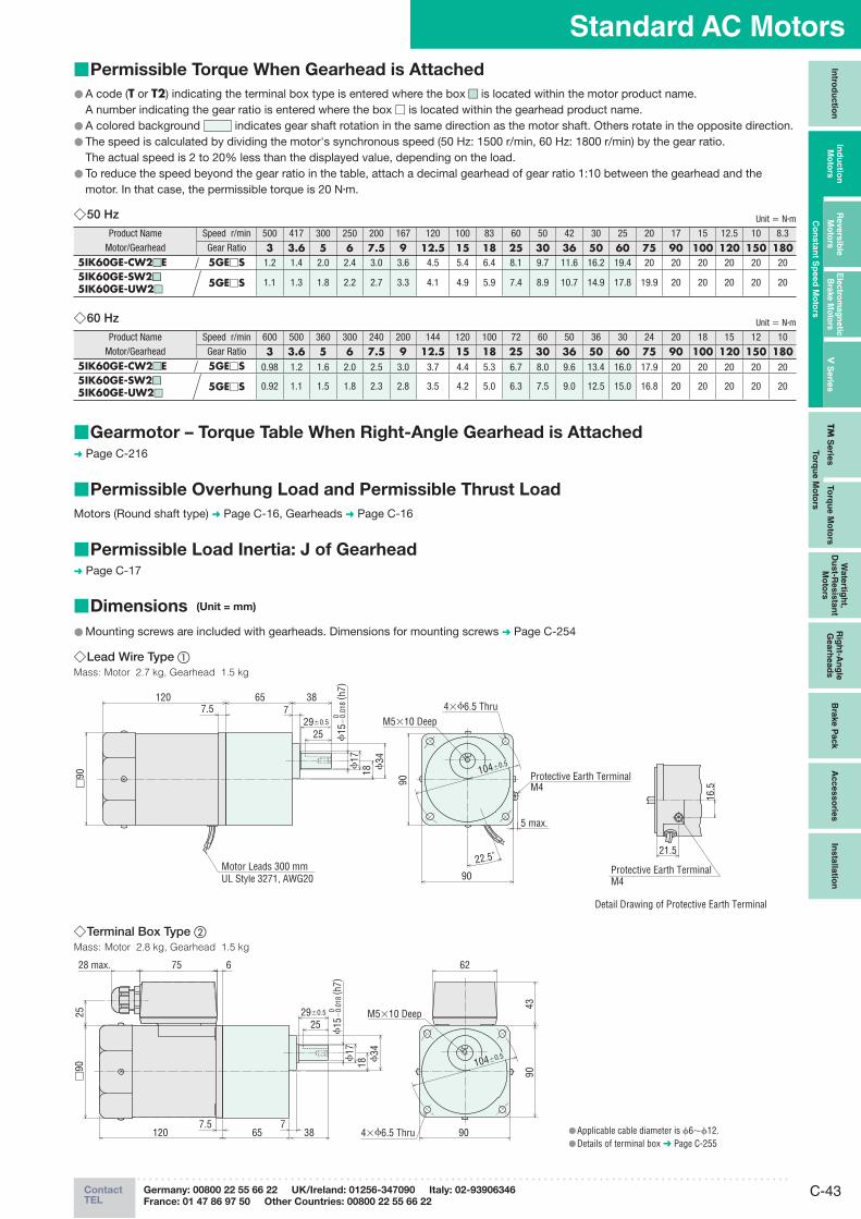
C-43ContactTEL
Germany: 00800 22 55 66 22 UK/Ireland: 01256-347090 Italy: 02-93906346
France: 01 47 86 97 50 Other Countries: 00800 22 55 66 22
Standard AC MotorsIn
trod
uctio
nIn
du
ctio
n
Mo
t ors
Revers
ible
M
oto
rsE
lectro
mag
netic
B
rake M
oto
rsV
Serie
sTM
Serie
sTo
rqu
e M
oto
rs
Wate
rtigh
t, D
ust-R
esis
tan
t M
oto
rs
Rig
ht-A
ng
le
Gearh
ead
sB
rake P
ack
Acc
es
so
ries
Insta
llatio
n
Co
nsta
nt S
peed
Mo
tors
To
rqu
e M
oto
rs
Permissible Torque When Gearhead is Attached ■
A code ( ● T or T2) indicating the terminal box type is entered where the box ■■ is located within the motor product name. A number indicating the gear ratio is entered where the box □ is located within the gearhead product name.
A colored background ● indicates gear shaft rotation in the same direction as the motor shaft. Others rotate in the opposite direction.The speed is calculated by dividing the motor's synchronous speed (50 Hz: 1500 r/min, 60 Hz: 1800 r/min) by the gear ratio. ●
The actual speed is 2 to 20% less than the displayed value, depending on the load.To reduce the speed beyond the gear ratio in the table, attach a decimal gearhead of gear ratio 1:10 between the gearhead and the ●motor. In that case, the permissible torque is 20 N·m.
50 Hz ◇ Unit = N·m
Product Name Speed r/min 500 417 300 250 200 167 120 100 83 60 50 42 30 25 20 17 15 12.5 10 8.3Motor/Gearhead Gear Ratio 3 3.6 5 6 7.5 9 12.5 15 18 25 30 36 50 60 75 90 100 120 150 180
5IK60GE-CW2 ■ ■E 5GE□S 1.2 1.4 2.0 2.4 3.0 3.6 4.5 5.4 6.4 8.1 9.7 11.6 16.2 19.4 20 20 20 20 20 205IK60GE-SW2 ■ ■
5IK60GE-UW2 ■ ■5GE□S 1.1 1.3 1.8 2.2 2.7 3.3 4.1 4.9 5.9 7.4 8.9 10.7 14.9 17.8 19.9 20 20 20 20 20
60 Hz ◇ Unit = N·m
Product Name Speed r/min 600 500 360 300 240 200 144 120 100 72 60 50 36 30 24 20 18 15 12 10Motor/Gearhead Gear Ratio 3 3.6 5 6 7.5 9 12.5 15 18 25 30 36 50 60 75 90 100 120 150 180
5IK60GE-CW2 ■ ■E 5GE□S 0.98 1.2 1.6 2.0 2.5 3.0 3.7 4.4 5.3 6.7 8.0 9.6 13.4 16.0 17.9 20 20 20 20 205IK60GE-SW2 ■ ■
5IK60GE-UW2 ■ ■5GE□S 0.92 1.1 1.5 1.8 2.3 2.8 3.5 4.2 5.0 6.3 7.5 9.0 12.5 15.0 16.8 20 20 20 20 20
Gearmotor – Torque Table When Right-Angle Gearhead is Attached ■➜ Page C-216
Permissible Overhung Load and Permissible Thrust Load ■
Motors (Round shaft type) ➜ Page C-16, Gearheads ➜ Page C-16
Permissible Load Inertia: J of Gearhead ■➜ Page C-17
Dimensions ■ (Unit = mm)
Mounting screws are included with gearheads. Dimensions for mounting screws ● ➜ Page C-254
Lead Wire Type ◇ ①Mass: Motor 2.7 kg, Gearhead 1.5 kg
�90
120 6577.5
18 �34
90
38
Motor Leads 300 mmUL Style 3271, AWG20
4��6.5 Thru
104�0.5
�15
�0.
018
( h7)
0
90
M5�10 Deep
5 max.
25
�17
29�0.5
Protective Earth TerminalM4
22.5˚
16.5
21.5
Detail Drawing of Protective Earth Terminal
Protective Earth TerminalM4
Terminal Box Type ◇ ②Mass: Motor 2.8 kg, Gearhead 1.5 kg
�90
120 6577.5
18 �34
9038 4��6.5 Thru
104�0.5
28 max. 75 6
43
25
62
�15
�0.
018
( h7)
0
90
M5�10 Deep25
�17
29�0.5
Applicable cable diameter is ● ϕ6∼ϕ12.Details of terminal box ● ➜ Page C-255
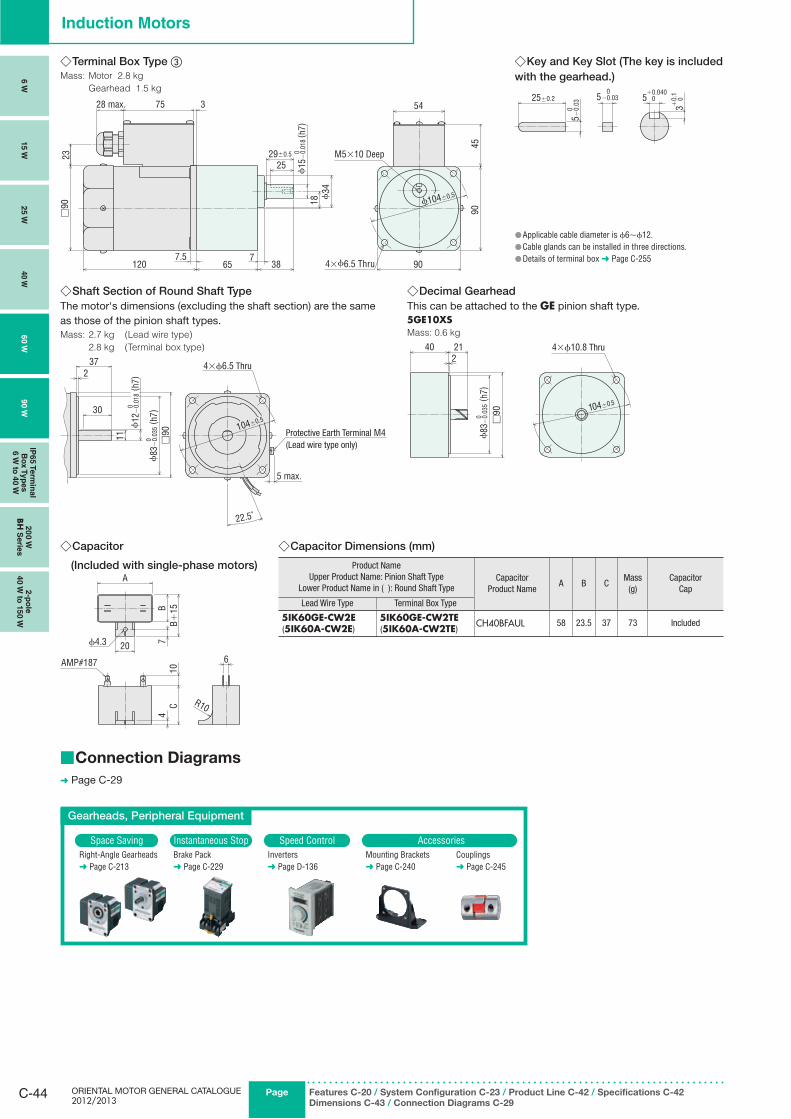
ORIENTAL MOTOR GENERAL CATALOGUE 2012/2013
C-44 Page Features C-20 / System Configuration C-23 / Product Line C-42 / Specifications C-42
Dimensions C-43 / Connection Diagrams C-29
Induction Motors
Terminal Box Type ◇ ③Mass: Motor 2.8 kg
Gearhead 1.5 kg
4590
90
54
18 ϕ34
□90
23
7.5 7120 65 38
ϕ15
−0.
018
( h7)
0
375
ϕ104±0.5
2529±0.5
28 max.
M5�10 Deep
4��6.5 Thru
Key and Key Slot (The key is included ◇with the gearhead.)
25±0.2 5 0 +0.040
3 0 +0.
1
5−0.
03 0
5−0.03 0
Applicable cable diameter is ● ϕ6∼ϕ12.Cable glands can be installed in three directions. ●Details of terminal box ● ➜ Page C-255
Shaft Section of Round Shaft Type ◇The motor's dimensions (excluding the shaft section) are the same as those of the pinion shaft types.Mass: 2.7 kg (Lead wire type)
2.8 kg (Terminal box type)
104±0.530
372
11 □90
22.5˚
ϕ12
−0.
018
( h7)
0
ϕ83
−0.
035
( h7)
0
5 max.
4×ϕ6.5 Thru
Protective Earth Terminal M4(Lead wire type only)
Decimal Gearhead ◇This can be attached to the GE pinion shaft type.5GE10XSMass: 0.6 kg
40 212
104±0.5
ϕ83
−0.
035
( h7)
0
□90
4×ϕ10.8 Thru
6
A
CB
720
10
AMP#187
ϕ4.3
4B+
15
R10
Capacitor Dimensions (mm) ◇
Product NameUpper Product Name: Pinion Shaft Type
Lower Product Name in ( ): Round Shaft TypeCapacitor
Product NameA B C
Mass(g)
CapacitorCap
Lead Wire Type Terminal Box Type
5IK60GE-CW2E (5IK60A-CW2E)
5IK60GE-CW2TE (5IK60A-CW2TE)
CH40BFAUL 58 23.5 37 73 Included
Capacitor ◇
(Included with single-phase motors)
Connection Diagrams ■
➜ Page C-29
Gearheads, Peripheral Equipment
Space Saving Instantaneous Stop Speed Control AccessoriesRight-Angle Gearheads➜ Page C-213
Brake Pack➜ Page C-229
Inverters➜ Page D-136
Mounting Brackets➜ Page C-240
Couplings➜ Page C-245
6 W
15 W
25 W
40 W
60 W
90 W
IP65 T
erm
inal
Bo
x T
yp
es
6 W
to 4
0 W
20
0 W
BH
Serie
s2-p
ole
40 W
to 1
50 W
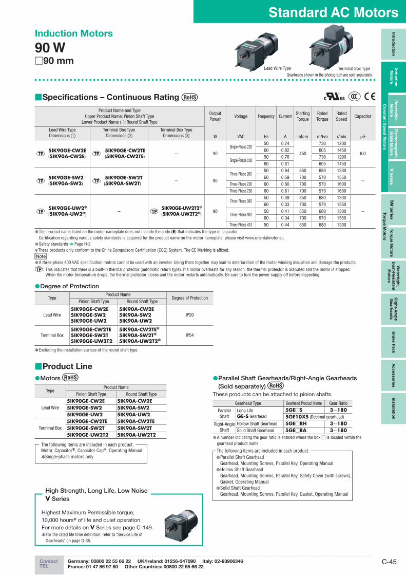
C-45ContactTEL
Germany: 00800 22 55 66 22 UK/Ireland: 01256-347090 Italy: 02-93906346
France: 01 47 86 97 50 Other Countries: 00800 22 55 66 22
Standard AC MotorsIn
trod
uctio
nIn
du
ctio
n
Mo
t ors
Revers
ible
M
oto
rsE
lectro
mag
netic
B
rake M
oto
rsV
Serie
sTM
Serie
sTo
rqu
e M
oto
rs
Wate
rtigh
t, D
ust-R
esis
tan
t M
oto
rs
Rig
ht-A
ng
le
Gearh
ead
sB
rake P
ack
Acc
es
so
ries
Insta
llatio
n
Co
nsta
nt S
peed
Mo
tors
To
rqu
e M
oto
rs
Induction Motors
90 W □90 mm
Gearheads shown in the photograph are sold separately.
Specifications – Continuous Rating ■
Product Name and TypeUpper Product Name: Pinion Shaft Type
Lower Product Name ( ): Round Shaft Type
OutputPower
Voltage Frequency CurrentStartingTorque
RatedTorque
RatedSpeed
Capacitor
Lead Wire TypeDimensions ①
Terminal Box TypeDimensions ②
Terminal Box TypeDimensions ③ W VAC Hz A mN·m mN·m r/min μF
5IK90GE-CW2E(5IK90A-CW2E)
5IK90GE-CW2TE(5IK90A-CW2TE)
− 90Single-Phase 220
50 0.74
450
730 1200
6.060 0.82 605 1450
Single-Phase 23050 0.76 730 120060 0.81 605 1450
5IK90GE-SW2(5IK90A-SW2)
5IK90GE-SW2T(5IK90A-SW2T)
− 90Three-Phase 200
50 0.64 850 680 1300
−60 0.59 700 570 1550
Three-Phase 220 60 0.60 700 570 1600Three-Phase 230 60 0.61 700 570 1600
5IK90GE-UW2✽
(5IK90A-UW2✽)−
5IK90GE-UW2T2✽
(5IK90A-UW2T2✽)90
Three-Phase 38050 0.39 850 680 1300
−
60 0.33 700 570 1550
Three-Phase 40050 0.41 850 680 130060 0.34 700 570 1550
Three-Phase 415 50 0.44 850 680 1300The product name listed on the motor nameplate does not include the code ( ● E) that indicates the type of capacitor.Certification regarding various safety standards is acquired for the product name on the motor nameplate, please visit www.orientalmotor.eu.Safety standards ● ➜ Page H-2 These products only conform to the China Compulsory Certification (CCC) System. The CE Marking is affixed. ✽
NoteA three-phase 400 VAC specification motors cannot be used with an inverter. Using them together may lead to deterioration of the motor winding insulation and damage the products. ●
: This indicates that there is a built-in thermal protector (automatic return type). If a motor overheats for any reason, the thermal protector is activated and the motor is stopped. When the motor temperature drops, the thermal protector closes and the motor restarts automatically. Be sure to turn the power supply off before inspecting.
Degree of Protection ●
TypeProduct Name
Degree of ProtectionPinion Shaft Type Round Shaft Type
Lead Wire5IK90GE-CW2E5IK90GE-SW25IK90GE-UW2
5IK90A-CW2E5IK90A-SW25IK90A-UW2
IP20
Terminal Box5IK90GE-CW2TE5IK90GE-SW2T5IK90GE-UW2T2
5IK90A-CW2TE✽
5IK90A-SW2T✽
5IK90A-UW2T2✽IP54
E ✽ xcluding the installation surface of the round shaft type.
Terminal Box TypeLead Wire Type
Product Line ■
Motors ●
TypeProduct Name
Pinion Shaft Type Round Shaft Type
Lead Wire5IK90GE-CW2E 5IK90A-CW2E5IK90GE-SW2 5IK90A-SW25IK90GE-UW2 5IK90A-UW2
Terminal Box5IK90GE-CW2TE 5IK90A-CW2TE5IK90GE-SW2T 5IK90A-SW2T5IK90GE-UW2T2 5IK90A-UW2T2
Motor, Capacitor✽, Capacitor Cap✽, Operating ManualSingle-phase motors only ✽
The following items are included in each product.
Parallel Shaft Gearheads/Right-Angle Gearheads ●(Sold separately)
These products can be attached to pinion shafts.
Gearhead Type Gearhead Product Name Gear Ratio
Parallel Shaft
Long LifeGE-S Gearhead
5GE□S 3∼1805GE10XS (Decimal gearhead)
Right-Angle Shaft
Hollow Shaft Gearhead 5GE□RH 3∼180Solid Shaft Gearhead 5GE□RA 3∼180
A number indicating the gear ratio is entered where the box ● □ is located within the gearhead product name.
Parallel Shaft Gearhead ●Gearhead, Mounting Screws, Parallel Key, Operating ManualHollow Shaft Gearhead ●Gearhead, Mounting Screws, Parallel Key, Safety Cover (with screws),Gasket, Operating ManualSolid Shaft Gearhead ●Gearhead, Mounting Screws, Parallel Key, Gasket, Operating Manual
The following items are included in each product.
Highest Maximum Permissible torque, 10,000 hours✽ of life and quiet operation. For more details on V Series see page C-149.
For the rated life time definition, refer to "Service Life of ✽
Gearheads" on page G-35.
High Strength, Long Life, Low NoiseV Series
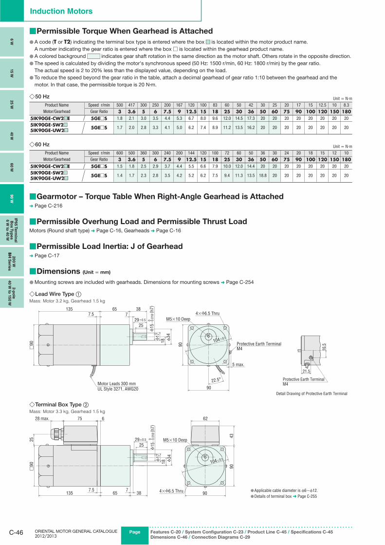
ORIENTAL MOTOR GENERAL CATALOGUE 2012/2013
C-46 Page Features C-20 / System Configuration C-23 / Product Line C-45 / Specifications C-45
Dimensions C-46 / Connection Diagrams C-29
Induction Motors
Terminal Box Type ◇ ②Mass: Motor 3.3 kg, Gearhead 1.5 kg
□90
135 65 387
18 ϕ34
7.5
28 max. 75 6
25
90
104±0.5
43
62
4×ϕ6.5 Thru
90
ϕ15
−0.
018
( h7)
0 M5×10 Deep25
ϕ17
29±0.5
Applicable cable diameter is ● ϕ6∼ϕ12.Details of terminal box ● ➜ Page C-255
Permissible Torque When Gearhead is Attached ■
A code ( ● T or T2) indicating the terminal box type is entered where the box ■■ is located within the motor product name. A number indicating the gear ratio is entered where the box □ is located within the gearhead product name.
A colored background ● indicates gear shaft rotation in the same direction as the motor shaft. Others rotate in the opposite direction.The speed is calculated by dividing the motor's synchronous speed (50 Hz: 1500 r/min, 60 Hz: 1800 r/min) by the gear ratio. ●
The actual speed is 2 to 20% less than the displayed value, depending on the load.To reduce the speed beyond the gear ratio in the table, attach a decimal gearhead of gear ratio 1:10 between the gearhead and the ●motor. In that case, the permissible torque is 20 N·m.
50 Hz ◇ Unit = N·m
Product Name Speed r/min 500 417 300 250 200 167 120 100 83 60 50 42 30 25 20 17 15 12.5 10 8.3Motor/Gearhead Gear Ratio 3 3.6 5 6 7.5 9 12.5 15 18 25 30 36 50 60 75 90 100 120 150 180
5IK90GE-CW2 ■ ■E 5GE□S 1.8 2.1 3.0 3.5 4.4 5.3 6.7 8.0 9.6 12.0 14.5 17.3 20 20 20 20 20 20 20 20
5IK90GE-SW2 ■ ■
5IK90GE-UW2 ■ ■5GE□S 1.7 2.0 2.8 3.3 4.1 5.0 6.2 7.4 8.9 11.2 13.5 16.2 20 20 20 20 20 20 20 20
60 Hz ◇ Unit = N·m
Product Name Speed r/min 600 500 360 300 240 200 144 120 100 72 60 50 36 30 24 20 18 15 12 10Motor/Gearhead Gear Ratio 3 3.6 5 6 7.5 9 12.5 15 18 25 30 36 50 60 75 90 100 120 150 180
5IK90GE-CW2 ■ ■E 5GE□S 1.5 1.8 2.5 2.9 3.7 4.4 5.5 6.6 7.9 10.0 12.0 14.4 20 20 20 20 20 20 20 20
5IK90GE-SW2 ■ ■
5IK90GE-UW2 ■ ■5GE□S 1.4 1.7 2.3 2.8 3.5 4.2 5.2 6.2 7.5 9.4 11.3 13.5 18.8 20 20 20 20 20 20 20
Gearmotor – Torque Table When Right-Angle Gearhead is Attached ■➜ Page C-216
Permissible Overhung Load and Permissible Thrust Load ■Motors (Round shaft type) ➜ Page C-16, Gearheads ➜ Page C-16
Permissible Load Inertia: J of Gearhead ■➜ Page C-17
Dimensions ■ (Unit = mm)
Mounting screws are included with gearheads. Dimensions for mounting screws ● ➜ Page C-254
Lead Wire Type ◇ ①Mass: Motor 3.2 kg, Gearhead 1.5 kg
□90
135 65 387
18 ϕ34
90
7.5
Motor Leads 300 mmUL Style 3271, AWG20
4×ϕ6.5 Thru
90
104±0.5
ϕ15
−0.
018
( h7)
0
22.5°
M5×10 Deep
5 max.
25
ϕ17
29±0.5
Protective Earth TerminalM4 16
.5
21.5
Detail Drawing of Protective Earth Terminal
Protective Earth TerminalM4
6 W
15 W
25 W
40 W
60 W
90 W
IP65 T
erm
inal
Bo
x T
yp
es
6 W
to 4
0 W
20
0 W
BH
Serie
s2-p
ole
40 W
to 1
50 W

C-47ContactTEL
Germany: 00800 22 55 66 22 UK/Ireland: 01256-347090 Italy: 02-93906346
France: 01 47 86 97 50 Other Countries: 00800 22 55 66 22
Standard AC MotorsIn
trod
uctio
nIn
du
ctio
n
Mo
t ors
Revers
ible
M
oto
rsE
lectro
mag
netic
B
rake M
oto
rsV
Serie
sTM
Serie
sTo
rqu
e M
oto
rs
Wate
rtigh
t, D
ust-R
esis
tan
t M
oto
rs
Rig
ht-A
ng
le
Gearh
ead
sB
rake P
ack
Acc
es
so
ries
Insta
llatio
n
Co
nsta
nt S
peed
Mo
tors
To
rqu
e M
oto
rs
Terminal Box Type ◇ ③Mass: Motor 3.3 kg
Gearhead 1.5 kg
4590
90
54
18 ϕ34
□90
23
7.5 7135 65 38
ϕ15
−0.
018
( h7)
029±0.5
25
375
ϕ104±0.5
4×ϕ6.5 Thru
28max.
M5 ×10 Deep
Key and Key Slot (The key is included ◇with the gearhead.)
25±0.2 5 0 +0.040
3 0 +0.
1
5−0.
03 0
5−0.03 0
Shaft Section of Round Shaft Type ◇The motor's dimensions (excluding the shaft section) are the same as those of the pinion shaft types.Mass: 3.2 kg (Lead wire type)
3.3 kg (Terminal box type)
104±0.530
372
11 □90
22.5˚
ϕ12
−0.
018
( h7)
0
ϕ83
−0.
035
( h7)
0
5 max.
4×ϕ6.5 Thru
Protective Earth Terminal M4(Lead wire type only)
Decimal Gearhead ◇This can be attached to the GE pinion shaft type.5GE10XSMass: 0.6 kg
40 212
104±0.5
ϕ83
−0.
035
( h7)
0
□90
4×ϕ10.8 Thru
Applicable cable diameter is ● ϕ6∼ϕ12.Cable glands can be installed in three directions. ●Details of terminal box ● ➜ Page C-255
6
A
CB
720
10
AMP#187
ϕ4.3
4B+
15
R10
Capacitor Dimensions (mm) ◇
Product NameUpper Product Name: Pinion Shaft Type
Lower Product Name in ( ): Round Shaft TypeCapacitor
Product NameA B C
Mass(g)
CapacitorCap
Lead Wire Type Terminal Box Type
5IK90GE-CW2E(5IK90A-CW2E)
5IK90GE-CW2TE(5IK90A-CW2TE)
CH60BFAUL 58 29 41 92 Included
Capacitor ◇ (Included with single-phase motors)
Connection Diagrams ■➜ Page C-29
Gearheads, Peripheral Equipment
Space Saving Instantaneous Stop Speed Control AccessoriesRight-Angle Gearheads➜ Page C-213
Brake Pack➜ Page C-229
Inverters➜ Page D-136
Mounting Brackets➜ Page C-240
Couplings➜ Page C-245
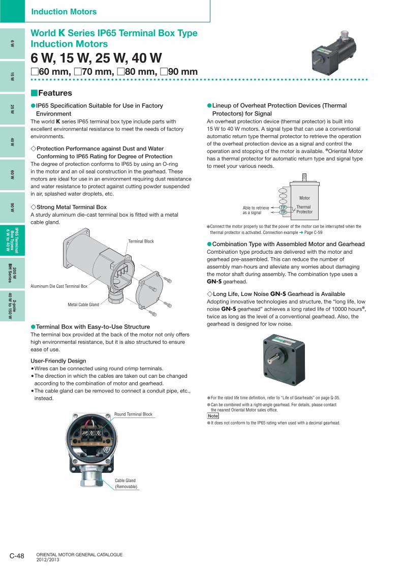
ORIENTAL MOTOR GENERAL CATALOGUE 2012/2013
C-48
Induction Motors
6 W
15 W
25 W
40 W
60 W
90 W
IP65 T
erm
inal
Bo
x T
yp
es
6 W
to 4
0 W
20
0 W
BH
Serie
s2-p
ole
40 W
to 1
50 W
World K Series IP65 Terminal Box Type
Induction Motors
6 W, 15 W, 25 W, 40 W□60 mm, □70 mm, □80 mm, □90 mm
Features ■
IP65 Specification Suitable for Use in Factory ●Environment
The world K series IP65 terminal box type include parts with excellent environmental resistance to meet the needs of factory environments.
Protection Performance against Dust and Water ◇Conforming to IP65 Rating for Degree of Protection
The degree of protection conforms to IP65 by using an O-ring in the motor and an oil seal construction in the gearhead. These motors are ideal for use in an environment requiring dust resistance and water resistance to protect against cutting powder suspended in air, splashed water droplets, etc.
Strong Metal Terminal Box ◇A sturdy aluminum die-cast terminal box is fitted with a metal cable gland.
Terminal Block
Metal Cable Gland
Aluminum Die Cast Terminal Box
Terminal Box with Easy-to-Use Structure ●The terminal box provided at the back of the motor not only offers high environmental resistance, but it is also structured to ensure ease of use.
User-Friendly DesignWires can be connected using round crimp terminals. ●The direction in which the cables are taken out can be changed ●according to the combination of motor and gearhead.The cable gland can be removed to connect a conduit pipe, etc., ●instead.
Lineup ● of Overheat Protection Devices (Thermal Protectors) for Signal
An overheat protection device (thermal protector) is built into 15 W to 40 W motors. A signal type that can use a conventional automatic return type thermal protector to retrieve the operation of the overheat protection device as a signal and control the operation and stopping of the motor is available. ✽Oriental Motor has a thermal protector for automatic return type and signal type to meet your various needs.
Connect the motor properly so that the power of the motor can be interrupted when the ✽
thermal protector is activated. Connection example ➜ Page C-59
Combination Type with Assembled Motor and Gearhead ●Combination type products are delivered with the motor and gearhead pre-assembled. This can reduce the number of assembly man-hours and alleviate any worries about damaging the motor shaft during assembly. The combination type uses a GN-S gearhead.
Long Life, Low Noise ◇ GN-S Gearhead is AvailableAdopting innovative technologies and structure, the “long life, low noise GN-S gearhead” achieves a long rated life of 10000 hours✽, twice as long as the level of a conventional gearhead. Also, the gearhead is designed for low noise.
For the rated life time definition, refer to “Life of Gearheads” on page G-35. ✽
● Can be combined with a right-angle gearhead. For details, please contact the nearest Oriental Motor sales office.
Note
● It does not conform to the IP65 rating when used with a decimal gearhead.
Round Terminal Block
Cable Gland(Removable)
ThermalProtector
Able to retrieveas a signal TP
TP
Motor
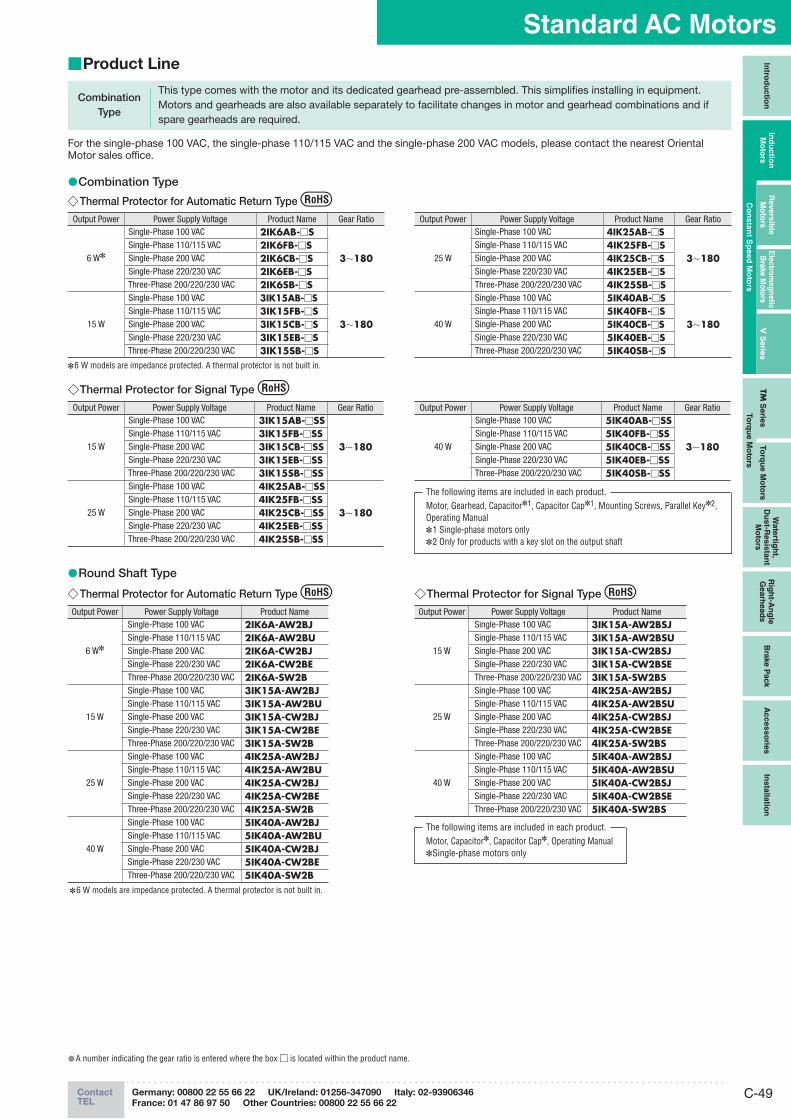
C-49ContactTEL
Germany: 00800 22 55 66 22 UK/Ireland: 01256-347090 Italy: 02-93906346
France: 01 47 86 97 50 Other Countries: 00800 22 55 66 22
Standard AC MotorsIn
trod
uctio
nIn
du
ctio
n
Mo
t ors
Revers
ible
M
oto
rsE
lectro
mag
netic
B
rake M
oto
rsV
Serie
sTM
Serie
sTo
rqu
e M
oto
rs
Wate
rtigh
t, D
ust-R
esis
tan
t M
oto
rs
Rig
ht-A
ng
le
Gearh
ead
sB
rake P
ack
Acc
es
so
ries
Insta
llatio
n
Co
nsta
nt S
peed
Mo
tors
To
rqu
e M
oto
rs
Product Line ■
Combination Type
This type comes with the motor and its dedicated gearhead pre-assembled. This simplifies installing in equipment.Motors and gearheads are also available separately to facilitate changes in motor and gearhead combinations and if spare gearheads are required.
For the single-phase 100 VAC, the single-phase 110/115 VAC and the single-phase 200 VAC models, please contact the nearest Oriental Motor sales office.
Combination Type ●Thermal Protector for Automatic Return Type ◇
Output Power Power Supply Voltage Product Name Gear Ratio
6 W✽
Single-Phase 100 VAC 2IK6AB-□S
3∼180 Single-Phase 110/115 VAC 2IK6FB-□S Single-Phase 200 VAC 2IK6CB-□S Single-Phase 220/230 VAC 2IK6EB-□S Three-Phase 200/220/230 VAC 2IK6SB-□S
15 W
Single-Phase 100 VAC 3IK15AB-□S
3∼180 Single-Phase 110/115 VAC 3IK15FB-□S Single-Phase 200 VAC 3IK15CB-□S Single-Phase 220/230 VAC 3IK15EB-□S Three-Phase 200/220/230 VAC 3IK15SB-□S
Output Power Power Supply Voltage Product Name Gear Ratio
25 W
Single-Phase 100 VAC 4IK25AB-□S
3∼180Single-Phase 110/115 VAC 4IK25FB-□SSingle-Phase 200 VAC 4IK25CB-□SSingle-Phase 220/230 VAC 4IK25EB-□SThree-Phase 200/220/230 VAC 4IK25SB-□S
40 W
Single-Phase 100 VAC 5IK40AB-□S
3∼180Single-Phase 110/115 VAC 5IK40FB-□SSingle-Phase 200 VAC 5IK40CB-□SSingle-Phase 220/230 VAC 5IK40EB-□SThree-Phase 200/220/230 VAC 5IK40SB-□S
Thermal Protector for Signal Type ◇Output Power Power Supply Voltage Product Name Gear Ratio
15 W
Single-Phase 100 VAC 3IK15AB-□SS
3∼180 Single-Phase 110/115 VAC 3IK15FB-□SS Single-Phase 200 VAC 3IK15CB-□SS Single-Phase 220/230 VAC 3IK15EB-□SS Three-Phase 200/220/230 VAC 3IK15SB-□SS
25 W
Single-Phase 100 VAC 4IK25AB-□SS
3∼180 Single-Phase 110/115 VAC 4IK25FB-□SS Single-Phase 200 VAC 4IK25CB-□SS Single-Phase 220/230 VAC 4IK25EB-□SS Three-Phase 200/220/230 VAC 4IK25SB-□SS
Output Power Power Supply Voltage Product Name Gear Ratio
40 W
Single-Phase 100 VAC 5IK40AB-□SS
3∼180 Single-Phase 110/115 VAC 5IK40FB-□SS Single-Phase 200 VAC 5IK40CB-□SS Single-Phase 220/230 VAC 5IK40EB-□SS Three-Phase 200/220/230 VAC 5IK40SB-□SS
The following items are included in each product.Motor, Gearhead, Capacitor✽1, Capacitor Cap✽1, Mounting Screws, Parallel Key✽2, Operating Manual
1 Single-phase motors only ✽
2 Only for products with a key slot on the output shaft ✽
Round Shaft Type ●
Thermal Protector for Automatic Return Type ◇Output Power Power Supply Voltage Product Name
6 W✽
Single-Phase 100 VAC 2IK6A-AW2BJSingle-Phase 110/115 VAC 2IK6A-AW2BUSingle-Phase 200 VAC 2IK6A-CW2BJSingle-Phase 220/230 VAC 2IK6A-CW2BEThree-Phase 200/220/230 VAC 2IK6A-SW2B
15 W
Single-Phase 100 VAC 3IK15A-AW2BJSingle-Phase 110/115 VAC 3IK15A-AW2BUSingle-Phase 200 VAC 3IK15A-CW2BJSingle-Phase 220/230 VAC 3IK15A-CW2BEThree-Phase 200/220/230 VAC 3IK15A-SW2B
25 W
Single-Phase 100 VAC 4IK25A-AW2BJSingle-Phase 110/115 VAC 4IK25A-AW2BUSingle-Phase 200 VAC 4IK25A-CW2BJSingle-Phase 220/230 VAC 4IK25A-CW2BEThree-Phase 200/220/230 VAC 4IK25A-SW2B
40 W
Single-Phase 100 VAC 5IK40A-AW2BJSingle-Phase 110/115 VAC 5IK40A-AW2BUSingle-Phase 200 VAC 5IK40A-CW2BJSingle-Phase 220/230 VAC 5IK40A-CW2BEThree-Phase 200/220/230 VAC 5IK40A-SW2B
6 W models are impedance protected. A thermal protector is not built in. ✽
Thermal Protector for Signal Type ◇Output Power Power Supply Voltage Product Name
15 W
Single-Phase 100 VAC 3IK15A-AW2BSJSingle-Phase 110/115 VAC 3IK15A-AW2BSUSingle-Phase 200 VAC 3IK15A-CW2BSJSingle-Phase 220/230 VAC 3IK15A-CW2BSEThree-Phase 200/220/230 VAC 3IK15A-SW2BS
25 W
Single-Phase 100 VAC 4IK25A-AW2BSJSingle-Phase 110/115 VAC 4IK25A-AW2BSUSingle-Phase 200 VAC 4IK25A-CW2BSJSingle-Phase 220/230 VAC 4IK25A-CW2BSEThree-Phase 200/220/230 VAC 4IK25A-SW2BS
40 W
Single-Phase 100 VAC 5IK40A-AW2BSJSingle-Phase 110/115 VAC 5IK40A-AW2BSUSingle-Phase 200 VAC 5IK40A-CW2BSJSingle-Phase 220/230 VAC 5IK40A-CW2BSEThree-Phase 200/220/230 VAC 5IK40A-SW2BS
The following items are included in each product.Motor, Capacitor✽, Capacitor Cap✽, Operating Manual
Single-phase motors only ✽
A number indicating the gear ratio is entered where the box ● □ is located within the product name.
6 W models are impedance protected. A thermal protector is not built in. ✽
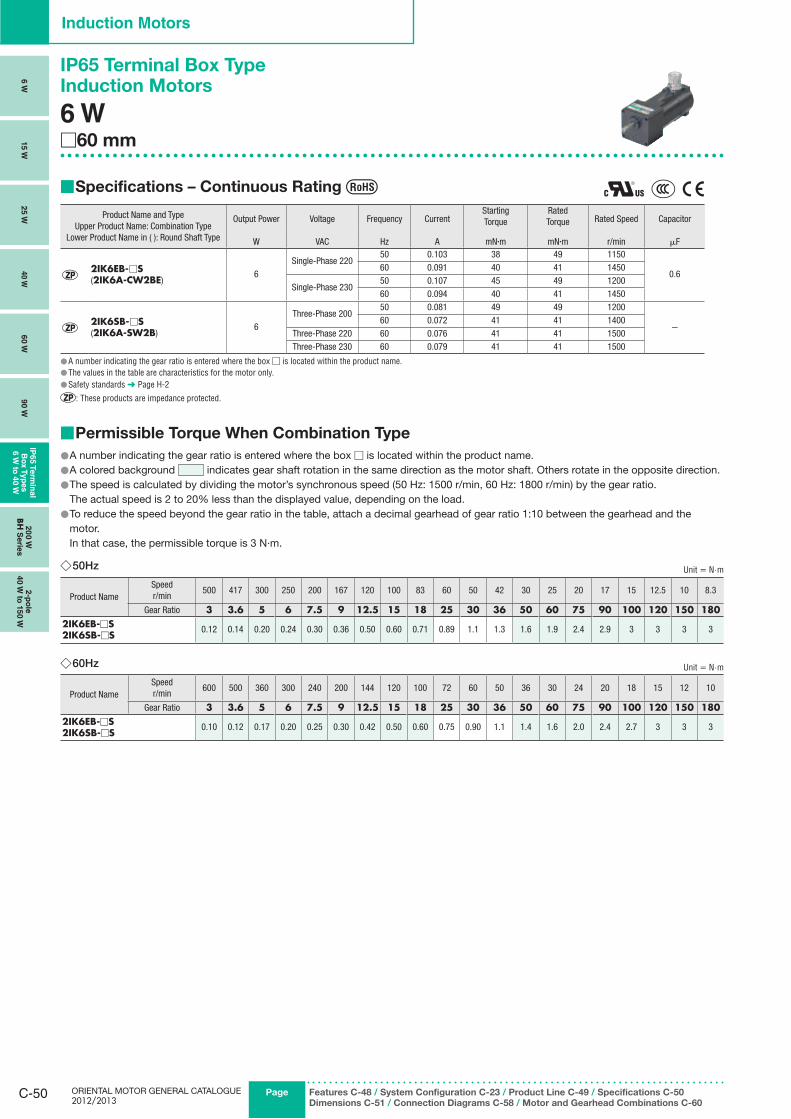
ORIENTAL MOTOR GENERAL CATALOGUE 2012/2013
C-50 Page Features C-48 / System Configuration C-23 / Product Line C-49 / Specifications C-50
Dimensions C-51 / Connection Diagrams C-58 / Motor and Gearhead Combinations C-60
Induction Motors
6 W
15 W
25 W
40 W
60 W
90 W
IP65 T
erm
inal
Bo
x T
yp
es
6 W
to 4
0 W
20
0 W
BH
Serie
s2-p
ole
40 W
to 1
50 W
Specifications – Continuous Rating ■
Product Name and TypeUpper Product Name: Combination Type
Lower Product Name in ( ): Round Shaft Type
Output Power Voltage Frequency CurrentStartingTorque
RatedTorque Rated Speed Capacitor
W VAC Hz A mN·m mN·m r/min μF
2IK6EB-□S(2IK6A-CW2BE)
6Single-Phase 220
50 0.103 38 49 1150
0.660 0.091 40 41 1450
Single-Phase 23050 0.107 45 49 120060 0.094 40 41 1450
2IK6SB-□S(2IK6A-SW2B)
6Three-Phase 200
50 0.081 49 49 1200
−60 0.072 41 41 1400
Three-Phase 220 60 0.076 41 41 1500Three-Phase 230 60 0.079 41 41 1500
A number indicating the gear ratio is entered where the box ● □ is located within the product name.The values in the table are characteristics for the motor only. ●Safety standards ● ➜ Page H-2
: These products are impedance protected.
Permissible Torque When Combination Type ■
A number indicating the gear ratio is entered where the box ● □ is located within the product name.A colore ● d background indicates gear shaft rotation in the same direction as the motor shaft. Others rotate in the opposite direction.The spee ● d is calculated by dividing the motor’s synchronous speed (50 Hz: 1500 r/min, 60 Hz: 1800 r/min) by the gear ratio.
The actual speed is 2 to 20% less than the displayed value, depending on the load. To reduce the speed beyond the gear ratio in the table, attach a decimal gearhead of gear ratio 1:10 between the gearhead and the ●motor.
In that case, the permissible torque is 3 N·m.
50Hz ◇ Unit = N.m
Product NameSpeedr/min
500 417 300 250 200 167 120 100 83 60 50 42 30 25 20 17 15 12.5 10 8.3
Gear Ratio 3 3.6 5 6 7.5 9 12.5 15 18 25 30 36 50 60 75 90 100 120 150 1802IK6EB-□S2IK6SB-□S
0.12 0.14 0.20 0.24 0.30 0.36 0.50 0.60 0.71 0.89 1.1 1.3 1.6 1.9 2.4 2.9 3 3 3 3
60Hz ◇ Unit = N.m
Product NameSpeedr/min
600 500 360 300 240 200 144 120 100 72 60 50 36 30 24 20 18 15 12 10
Gear Ratio 3 3.6 5 6 7.5 9 12.5 15 18 25 30 36 50 60 75 90 100 120 150 1802IK6EB-□S2IK6SB-□S
0.10 0.12 0.17 0.20 0.25 0.30 0.42 0.50 0.60 0.75 0.90 1.1 1.4 1.6 2.0 2.4 2.7 3 3 3
IP65 Terminal Box TypeInduction Motors
6 W□60 mm
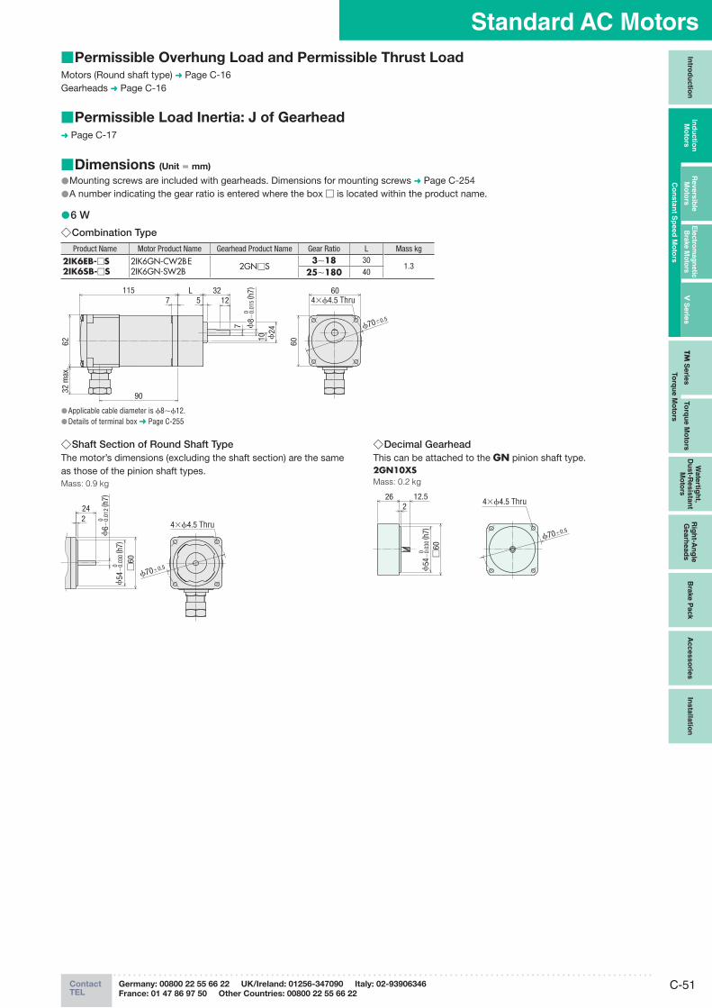
C-51ContactTEL
Germany: 00800 22 55 66 22 UK/Ireland: 01256-347090 Italy: 02-93906346
France: 01 47 86 97 50 Other Countries: 00800 22 55 66 22
Standard AC MotorsIn
trod
uctio
nIn
du
ctio
n
Mo
t ors
Revers
ible
M
oto
rsE
lectro
mag
netic
B
rake M
oto
rsV
Serie
sTM
Serie
sTo
rqu
e M
oto
rs
Wate
rtigh
t, D
ust-R
esis
tan
t M
oto
rs
Rig
ht-A
ng
le
Gearh
ead
sB
rake P
ack
Acc
es
so
ries
Insta
llatio
n
Co
nsta
nt S
peed
Mo
tors
To
rqu
e M
oto
rs
Permissible Overhung Load and Permissible Thrust Load ■Motors (Round shaft type) ➜ Page C-16Gearheads ➜ Page C-16
Permissible Load Inertia: J of Gearhead ■➜ Page C-17
Dimensions ■ (Unit = mm)
Mounting screws are included with gearheads. Dimensions for mounting screws ● ➜ Page C-254A number indicating the gear ratio is entered where the box ● □ is located within the product name.
6 W ●Combination Type ◇Product Name Motor Product Name Gearhead Product Name Gear Ratio L Mass kg
2IK6EB-□S 2IK6SB-□S
2IK6GN-CW2BE2IK6GN-SW2B 2GN□S
3∼18 301.3
25∼180 40
62
90
1157
32 m
ax.
L5 12
ϕ24
32
10
7
4×ϕ4.5 Thru
ϕ70±0.5
ϕ8−
0.01
5 ( h
7)0
6060
Applicable cable diameter is ● ϕ8∼ϕ12.Details of terminal box ● ➜ Page C-255
Shaft Section of Round Shaft Type ◇The motor’s dimensions (excluding the shaft section) are the same as those of the pinion shaft types.Mass: 0.9 kg
224
□60
ϕ54
−0.
030
( h7)
0
ϕ6−
0.01
2 ( h
7)0
4×ϕ4.5 Thru
ϕ70±0.5
Decimal Gearhead ◇This can be attached to the GN pinion shaft type.2GN10XSMass: 0.2 kg
26 12.52
4×ϕ4.5 Thru
ϕ70±0.5
□60
ϕ54
−0.
030
( h7)
0
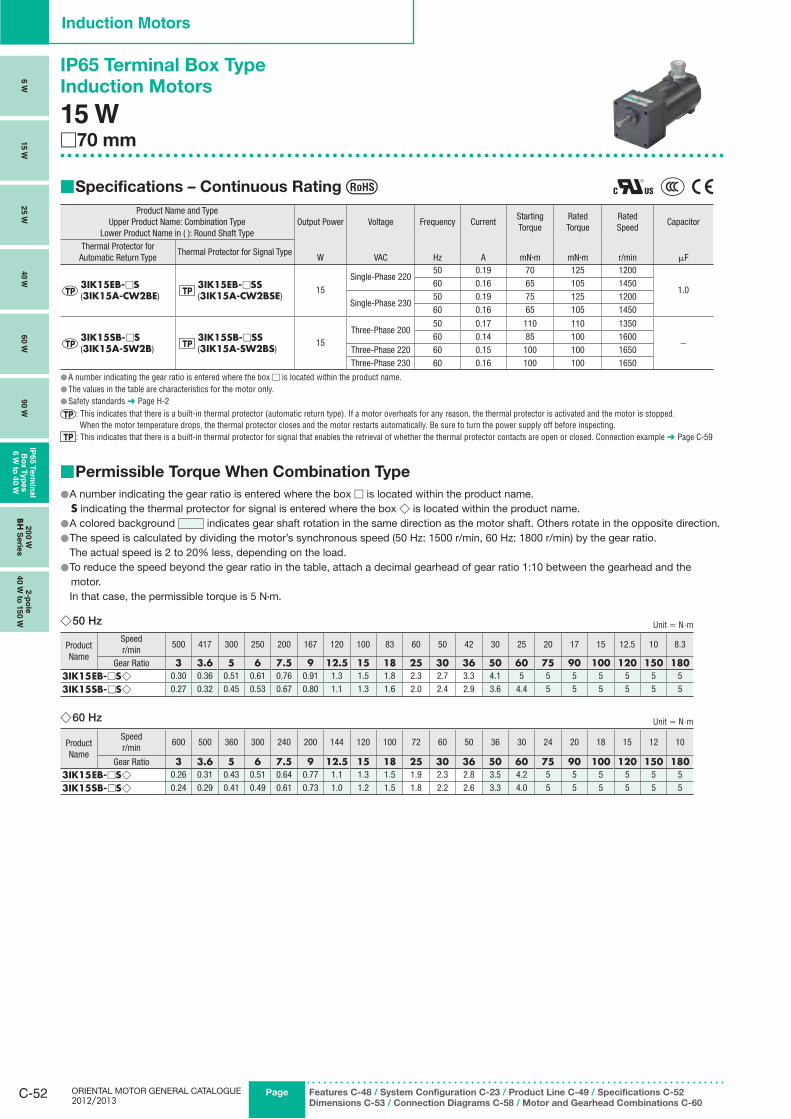
ORIENTAL MOTOR GENERAL CATALOGUE 2012/2013
C-52 Page
Induction Motors
6 W
15 W
25 W
40 W
60 W
90 W
IP65 T
erm
inal
Bo
x T
yp
es
6 W
to 4
0 W
20
0 W
BH
Serie
s2-p
ole
40 W
to 1
50 W
Features C-48 / System Configuration C-23 / Product Line C-49 / Specifications C-52
Dimensions C-53 / Connection Diagrams C-58 / Motor and Gearhead Combinations C-60
IP65 Terminal Box Type
Induction Motors
15 W□70 mm
Specifications – Continuous Rating ■
Product Name and TypeUpper Product Name: Combination Type
Lower Product Name in ( ): Round Shaft TypeOutput Power Voltage Frequency Current
Starting Torque
Rated Torque
RatedSpeed
Capacitor
Thermal Protector for Automatic Return Type
Thermal Protector for Signal TypeW VAC Hz A mN·m mN·m r/min μF
3IK15EB-□S(3IK15A-CW2BE)
3IK15EB-□SS(3IK15A-CW2BSE)
15Single-Phase 220
50 0.19 70 125 1200
1.0 60 0.16 65 105 1450
Single-Phase 23050 0.19 75 125 120060 0.16 65 105 1450
3IK15SB-□S(3IK15A-SW2B)
3IK15SB-□SS(3IK15A-SW2BS)
15Three-Phase 200
50 0.17 110 110 1350
−60 0.14 85 100 1600
Three-Phase 220 60 0.15 100 100 1650Three-Phase 230 60 0.16 100 100 1650
A number indicating the gear ratio is entered where the box ● □ is located within the product name.The values in the table are characteristics for the motor only. ●Safety standards ● ➜ Page H-2
: This indicates that there is a built-in thermal protector (automatic return type). If a motor overheats for any reason, the thermal protector is activated and the motor is stopped. When the motor temperature drops, the thermal protector closes and the motor restarts automatically. Be sure to turn the power supply off before inspecting.
: This indicates that there is a built-in thermal protector for signal that enables the retrieval of whether the thermal protector contacts are open or closed. Connection example ➜ Page C-59
Permissible Torque When Combination Type ■
A number indicating the gear ratio is entered where the box ● □ is located within the product name.S indicating the thermal protector for signal is entered where the box ◇ is located within the product name.A colored background ● indicates gear shaft rotation in the same direction as the motor shaft. Others rotate in the opposite direction.The speed is calculated by dividing the motor’s synchronous speed (50 Hz: 1500 r/min, 60 Hz: 1800 r/min) by the gear ratio. ●
The actual speed is 2 to 20% less, depending on the load.To reduce the speed beyond the gear ratio in the table, attach a decimal gearhead of gear ratio 1:10 between the gearhead and the ●motor.
In that case, the permissible torque is 5 N·m.
50 Hz ◇ Unit = N.m
Product Name
Speedr/min
500 417 300 250 200 167 120 100 83 60 50 42 30 25 20 17 15 12.5 10 8.3
Gear Ratio 3 3.6 5 6 7.5 9 12.5 15 18 25 30 36 50 60 75 90 100 120 150 1803IK15EB-□S◇ 0.30 0.36 0.51 0.61 0.76 0.91 1.3 1.5 1.8 2.3 2.7 3.3 4.1 5 5 5 5 5 5 5
3IK15SB-□S◇ 0.27 0.32 0.45 0.53 0.67 0.80 1.1 1.3 1.6 2.0 2.4 2.9 3.6 4.4 5 5 5 5 5 5
60 Hz ◇ Unit = N.m
Product Name
Speedr/min
600 500 360 300 240 200 144 120 100 72 60 50 36 30 24 20 18 15 12 10
Gear Ratio 3 3.6 5 6 7.5 9 12.5 15 18 25 30 36 50 60 75 90 100 120 150 1803IK15EB-□S◇ 0.26 0.31 0.43 0.51 0.64 0.77 1.1 1.3 1.5 1.9 2.3 2.8 3.5 4.2 5 5 5 5 5 5
3IK15SB-□S◇ 0.24 0.29 0.41 0.49 0.61 0.73 1.0 1.2 1.5 1.8 2.2 2.6 3.3 4.0 5 5 5 5 5 5
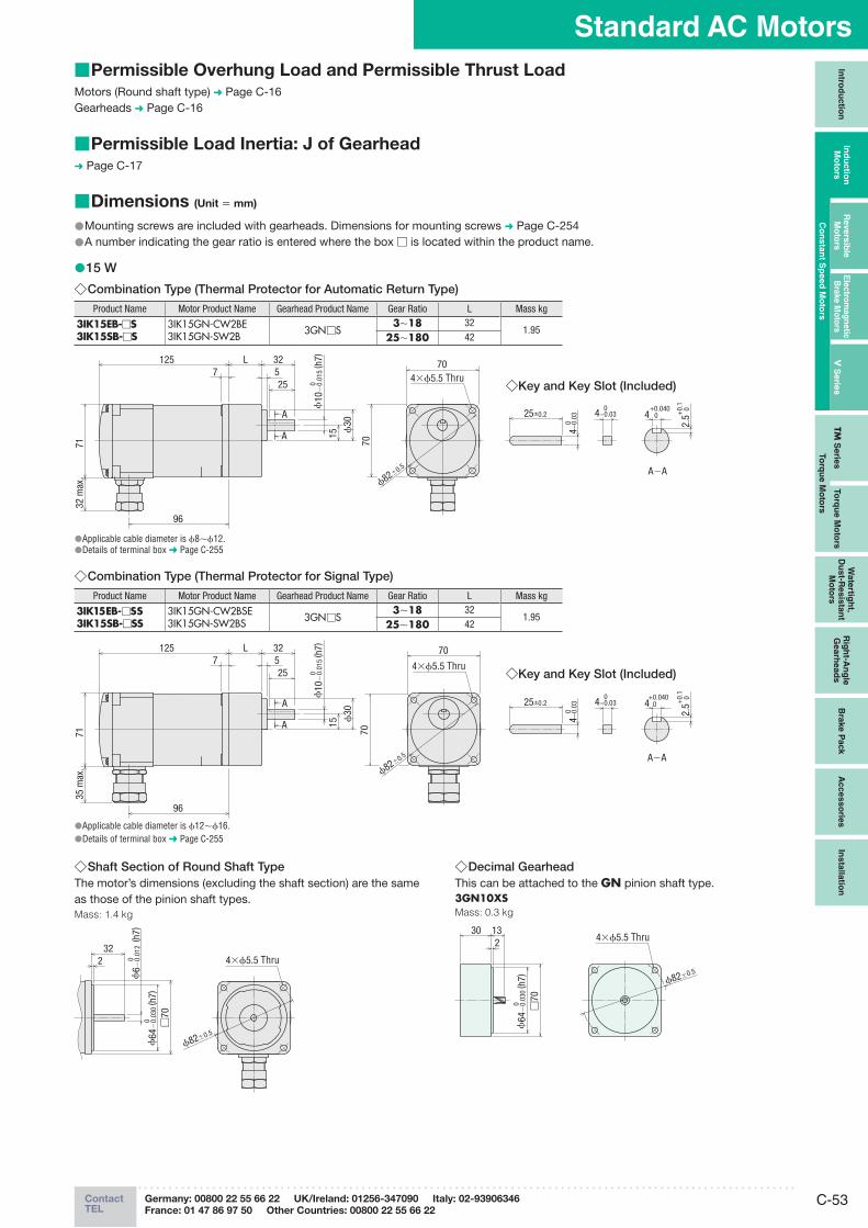
C-53ContactTEL
Germany: 00800 22 55 66 22 UK/Ireland: 01256-347090 Italy: 02-93906346
France: 01 47 86 97 50 Other Countries: 00800 22 55 66 22
Standard AC MotorsIn
trod
uctio
nIn
du
ctio
n
Mo
t ors
Revers
ible
M
oto
rsE
lectro
mag
netic
B
rake M
oto
rsV
Serie
sTM
Serie
sTo
rqu
e M
oto
rs
Wate
rtigh
t, D
ust-R
esis
tan
t M
oto
rs
Rig
ht-A
ng
le
Gearh
ead
sB
rake P
ack
Acc
es
so
ries
Insta
llatio
n
Co
nsta
nt S
peed
Mo
tors
To
rqu
e M
oto
rs
Dimensions ■ (Unit = mm)
Mounting screws are included with gearheads. Dimensions for mounting screws ● ➜ Page C-254A number indicating the gear ratio is entered where the box ● □ is located within the product name.
15 W ●Combination Type (Thermal Protector for Automatic Return Type) ◇
Product Name Motor Product Name Gearhead Product Name Gear Ratio L Mass kg
3IK15EB-□S3IK15SB-□S
3IK15GN-CW2BE3IK15GN-SW2B 3GN□S
3∼18 321.95
25∼180 42
●Applicable cable diameter is ϕ8∼ϕ12.●Details of terminal box ➜ Page C-255
Combination Type (Thermal Protector for Signal Type) ◇Product Name Motor Product Name Gearhead Product Name Gear Ratio L Mass kg
3IK15EB-□SS3IK15SB-□SS
3IK15GN-CW2BSE3IK15GN-SW2BS 3GN□S
3∼18 321.95
25∼180 42
●Applicable cable diameter is ϕ12∼ϕ16.●Details of terminal box ➜ Page C-255
Shaft Section of Round Shaft Type ◇The motor’s dimensions (excluding the shaft section) are the same as those of the pinion shaft types.Mass: 1.4 kg
ϕ82±0.5
4×ϕ5.5 Thru232
□70
ϕ64
−0.
030
( h7)
0
ϕ6 −
0.01
2 ( h
7)0
Decimal Gearhead ◇This can be attached to the GN pinion shaft type.3GN10XSMass: 0.3 kg
30 132 4×ϕ5.5 Thru
ϕ82±0.5
ϕ64
−0.
030
( h7)
0 □70
Permissible Overhung Load and Permissible Thrust Load ■Motors (Round shaft type) ➜ Page C-16Gearheads ➜ Page C-16
Permissible Load Inertia: J of Gearhead ■➜ Page C-17
32525
1257
L
ϕ10
−0.
015
( h7)
0
A
A 15 ϕ30
96
7135
max
.
A−A
25±0.2 4 0 +0.040
2.5
0 +0.
1
4−0.
03 0
4−0.03 0
ϕ82±0.5
70
70
4×ϕ5.5 Thru ◇Key and Key Slot (Included)
96
A
A
32525
1257
L
15 ϕ30
ϕ10
−0.
015
( h7)
0
7132
max
.
ϕ82±0.5
4×ϕ5.5 Thru
25±0.2 4 0 +0.040
2.5
0 +0.
1
4−0.
03 0
4−0.03 0
A−A
7070
◇Key and Key Slot (Included)
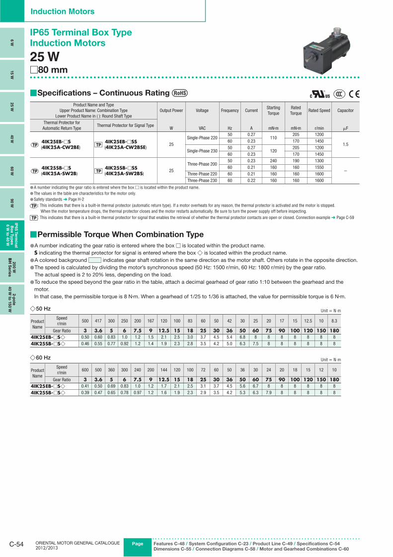
ORIENTAL MOTOR GENERAL CATALOGUE 2012/2013
C-54 Page
Induction Motors
6 W
15 W
25 W
40 W
60 W
90 W
IP65 T
erm
inal
Bo
x T
yp
es
6 W
to 4
0 W
20
0 W
BH
Serie
s2-p
ole
40 W
to 1
50 W
Features C-48 / System Configuration C-23 / Product Line C-49 / Specifications C-54
Dimensions C-55 / Connection Diagrams C-58 / Motor and Gearhead Combinations C-60
IP65 Terminal Box Type
Induction Motors
25 W□80 mm
Specifications – Continuous Rating ■
Product Name and TypeUpper Product Name: Combination Type
Lower Product Name in ( ): Round Shaft TypeOutput Power Voltage Frequency Current
Starting Torque
Rated Torque
Rated Speed Capacitor
Thermal Protector for Automatic Return Type
Thermal Protector for Signal TypeW VAC Hz A mN·m mN·m r/min μF
4IK25EB-□S (4IK25A-CW2BE)
4IK25EB-□SS (4IK25A-CW2BSE)
25Single-Phase 220
50 0.27110
205 1200
1.560 0.23 170 1450
Single-Phase 23050 0.27
120205 1200
60 0.23 170 1450
4IK25SB-□S (4IK25A-SW2B)
4IK25SB-□SS (4IK25A-SW2BS)
25Three-Phase 200
50 0.23 240 190 1300
−60 0.21 160 160 1550
Three-Phase 220 60 0.21 160 160 1600Three-Phase 230 60 0.22 160 160 1600
A number indicating the gear ratio is entered where the box ● □ is located within the product name.The values in the table are characteristics for the motor only. ●Safety standards ● ➜ Page H-2
: This indicates that there is a built-in thermal protector (automatic return type). If a motor overheats for any reason, the thermal protector is activated and the motor is stopped. When the motor temperature drops, the thermal protector closes and the motor restarts automatically. Be sure to turn the power supply off before inspecting.
: This indicates that there is a built-in thermal protector for signal that enables the retrieval of whether the thermal protector contacts are open or closed. Connection example ➜ Page C-59
Permissible Torque When Combination Type ■
A number indicating the gear ratio is entered where the box ● □ is located within the product name. S indicating the thermal protector for signal is entered where the box ◇ is located within the product name.
A colored background ● indicates gear shaft rotation in the same direction as the motor shaft. Others rotate in the opposite direction.The speed is calculated by dividing the motor’s synchronous speed (50 Hz: 1500 r/min, 60 Hz: 1800 r/min) by the gear ratio. ●
The actual speed is 2 to 20% less, depending on the load.To reduce the speed beyond the gear ratio in the table, attach a decimal gearhead of gear ratio 1:10 between the gearhead and the ●
motor. In that case, the permissible torque is 8 N·m. When a gearhead of 1/25 to 1/36 is attached, the value for permissible torque is 6 N·m.
50 Hz ◇ Unit = N.m
Product Name
Speedr/min
500 417 300 250 200 167 120 100 83 60 50 42 30 25 20 17 15 12.5 10 8.3
Gear Ratio 3 3.6 5 6 7.5 9 12.5 15 18 25 30 36 50 60 75 90 100 120 150 1804IK25EB-□S◇ 0.50 0.60 0.83 1.0 1.2 1.5 2.1 2.5 3.0 3.7 4.5 5.4 6.8 8 8 8 8 8 8 8
4IK25SB-□S◇ 0.46 0.55 0.77 0.92 1.2 1.4 1.9 2.3 2.8 3.5 4.2 5.0 6.3 7.5 8 8 8 8 8 8
60 Hz ◇ Unit = N.m
Product Name
Speedr/min
600 500 360 300 240 200 144 120 100 72 60 50 36 30 24 20 18 15 12 10
Gear Ratio 3 3.6 5 6 7.5 9 12.5 15 18 25 30 36 50 60 75 90 100 120 150 1804IK25EB-□S◇ 0.41 0.50 0.69 0.83 1.0 1.2 1.7 2.1 2.5 3.1 3.7 4.5 5.6 6.7 8 8 8 8 8 8
4IK25SB-□S◇ 0.39 0.47 0.65 0.78 0.97 1.2 1.6 1.9 2.3 2.9 3.5 4.2 5.3 6.3 7.9 8 8 8 8 8

C-55ContactTEL
Germany: 00800 22 55 66 22 UK/Ireland: 01256-347090 Italy: 02-93906346
France: 01 47 86 97 50 Other Countries: 00800 22 55 66 22
Standard AC MotorsIn
trod
uctio
nIn
du
ctio
n
Mo
t ors
Revers
ible
M
oto
rsE
lectro
mag
netic
B
rake M
oto
rsV
Serie
sTM
Serie
sTo
rqu
e M
oto
rs
Wate
rtigh
t, D
ust-R
esis
tan
t M
oto
rs
Rig
ht-A
ng
le
Gearh
ead
sB
rake P
ack
Acc
es
so
ries
Insta
llatio
n
Co
nsta
nt S
peed
Mo
tors
To
rqu
e M
oto
rs
Dimensions ■ (Unit = mm)
Mounting screws are included with gearheads. Dimensions for mounting screws ● ➜ Page C-254A number indicating the gear ratio is entered where the box ● □ is located within the product name.
25 W ●Combination Type (Thermal Protector for Automatic Return Type) ◇
Product Name Motor Product Name Gearhead Product Name Gear Ratio L Mass kg
4IK25EB-□S4IK25SB-□S
4IK25GN-CW2BE4IK25GN-SW2B 4GN□S
3∼18 322.55
25∼180 42.5
Applicable cable diameter is ● ϕ8∼ϕ12.Details of terminal box ● ➜ Page C-255
Combination Type (Thermal Protector for Signal Type) ◇
Product Name Motor Product Name Gearhead Product Name Gear Ratio L Mass kg
4IK25EB-□SS4IK25SB-□SS
4IK25GN-CW2BSE4IK25GN-SW2BS 4GN□S
3∼18 322.55
25∼180 42.5
Applicable cable diameter is ● ϕ12∼ϕ16.Details of terminal box ● ➜ Page C-255
Shaft Section of Round Shaft Type ◇The motor’s dimensions (excluding the shaft section) are the same as those of the pinion shaft types.Mass: 1.9 kg
ϕ94±0.5
4×ϕ5.5 Thru232
25
7
□80
ϕ73
−0.
030
( h7)
0
ϕ8 −
0.01
5 ( h
7)0
Decimal Gearhead ◇This can be attached to the GN pinion shaft type.4GN10XSMass: 0.4 kg
32 13.52
□80 ϕ94±0.5
ϕ73
−0.
030
( h7)
0
4×ϕ5.5 Thru
Permissible Overhung Load and Permissible Thrust Load ■Motors (Round shaft type) ➜ Page C-16Gearheads ➜ Page C-16
Permissible Load Inertia: J of Gearhead ■➜ Page C-17
81.5
32 m
ax.
131
98
32625
15A
A
7
Lϕ
34
ϕ94±0.5
ϕ10
−0.
015
( h7)
0
25±0.2 4 0 +0.040
2.5
0 +0.
1
4−0.
03 0
4−0.03 0
A−A
8080
4×ϕ5.5 Thru ◇Key and Key Slot (Included)
81.5
35 m
ax.
131
98
32625
15A
A
7
L
ϕ34
ϕ10
−0.
015
( h7)
0
ϕ94±0.5
25±0.2 4 0 +0.040
2.5
0 +0.
1
4−0.
03 0
4−0.03 0
A−A
80
80
4×ϕ5.5 Thru ◇Key and Key Slot (Included)
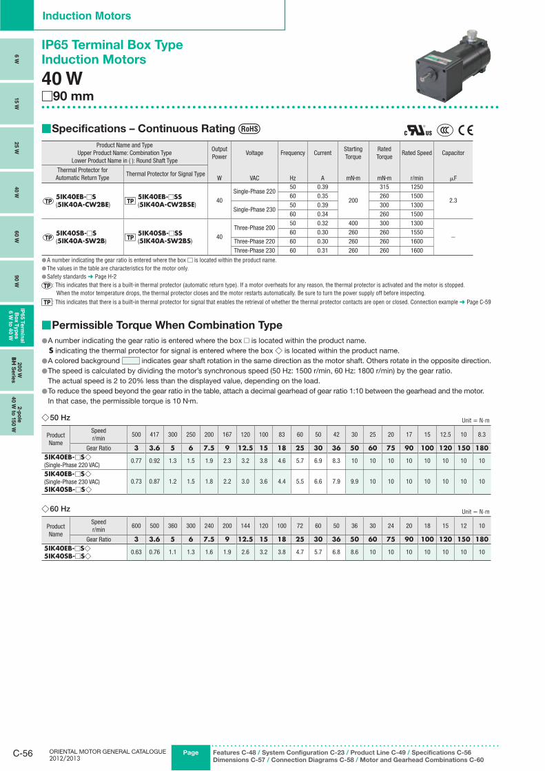
ORIENTAL MOTOR GENERAL CATALOGUE 2012/2013
C-56 Page
Induction Motors
6 W
15 W
25 W
40 W
60 W
90 W
IP65 T
erm
inal
Bo
x T
yp
es
6 W
to 4
0 W
20
0 W
BH
Serie
s2-p
ole
40 W
to 1
50 W
Features C-48 / System Configuration C-23 / Product Line C-49 / Specifications C-56
Dimensions C-57 / Connection Diagrams C-58 / Motor and Gearhead Combinations C-60
IP65 Terminal Box Type
Induction Motors
40 W□90 mm
Specifications – Continuous Rating ■
Product Name and TypeUpper Product Name: Combination Type
Lower Product Name in ( ): Round Shaft Type
Output Power
Voltage Frequency CurrentStarting Torque
Rated Torque
Rated Speed Capacitor
Thermal Protector for Automatic Return Type
Thermal Protector for Signal TypeW VAC Hz A mN·m mN·m r/min μF
5IK40EB-□S(5IK40A-CW2BE)
5IK40EB-□SS(5IK40A-CW2BSE)
40Single-Phase 220
50 0.39
200
315 1250
2.360 0.35 260 1500
Single-Phase 23050 0.39 300 130060 0.34 260 1500
5IK40SB-□S(5IK40A-SW2B)
5IK40SB-□SS(5IK40A-SW2BS)
40Three-Phase 200
50 0.32 400 300 1300
−60 0.30 260 260 1550
Three-Phase 220 60 0.30 260 260 1600Three-Phase 230 60 0.31 260 260 1600
A number indicating the gear ratio is entered where the box ● □ is located within the product name.The values in the table are characteristics for the motor only. ●Safety standards ● ➜ Page H-2
: This indicates that there is a built-in thermal protector (automatic return type). If a motor overheats for any reason, the thermal protector is activated and the motor is stopped. When the motor temperature drops, the thermal protector closes and the motor restarts automatically. Be sure to turn the power supply off before inspecting.
: This indicates that there is a built-in thermal protector for signal that enables the retrieval of whether the thermal protector contacts are open or closed. Connection example ➜ Page C-59
Permissible Torque When Combination Type ■
A number indicating the gear ratio is entered where the box ● □ is located within the product name.S indicating the thermal protector for signal is entered where the box ◇ is located within the product name.A colored background ● indicates gear shaft rotation in the same direction as the motor shaft. Others rotate in the opposite direction.The speed is calculated by dividing the motor’s synchronous speed (50 Hz: 1500 r/min, 60 Hz: 1800 r/min) by the gear ratio. ●
The actual speed is 2 to 20% less than the displayed value, depending on the load.To reduce the speed beyond the gear ratio in the table, attach a decimal gearhead of gear ratio 1:10 between the gearhead and the motor. ●
In that case, the permissible torque is 10 N·m.
50 Hz ◇ Unit = N.m
Product Name
Speedr/min
500 417 300 250 200 167 120 100 83 60 50 42 30 25 20 17 15 12.5 10 8.3
Gear Ratio 3 3.6 5 6 7.5 9 12.5 15 18 25 30 36 50 60 75 90 100 120 150 1805IK40EB-□S◇(Single-Phase 220 VAC)
0.77 0.92 1.3 1.5 1.9 2.3 3.2 3.8 4.6 5.7 6.9 8.3 10 10 10 10 10 10 10 10
5IK40EB-□S◇(Single-Phase 230 VAC)5IK40SB-□S◇
0.73 0.87 1.2 1.5 1.8 2.2 3.0 3.6 4.4 5.5 6.6 7.9 9.9 10 10 10 10 10 10 10
60 Hz ◇ Unit = N.m
Product Name
Speedr/min
600 500 360 300 240 200 144 120 100 72 60 50 36 30 24 20 18 15 12 10
Gear Ratio 3 3.6 5 6 7.5 9 12.5 15 18 25 30 36 50 60 75 90 100 120 150 1805IK40EB-□S◇5IK40SB-□S◇ 0.63 0.76 1.1 1.3 1.6 1.9 2.6 3.2 3.8 4.7 5.7 6.8 8.6 10 10 10 10 10 10 10
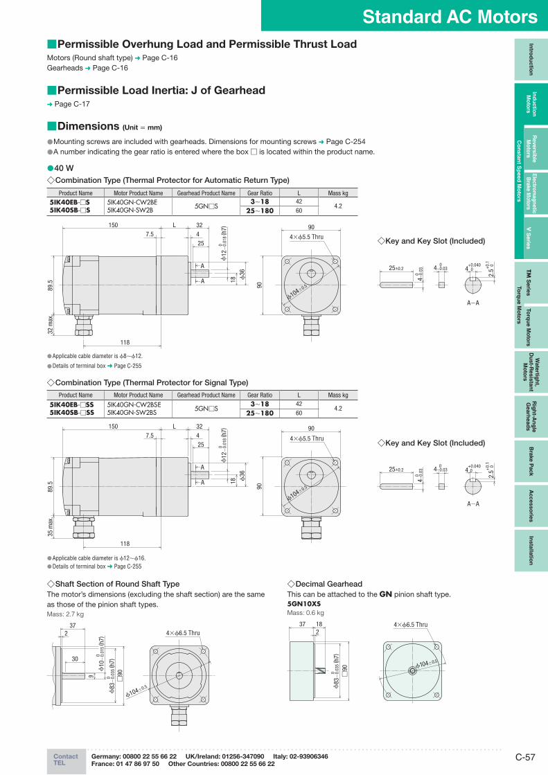
C-57ContactTEL
Germany: 00800 22 55 66 22 UK/Ireland: 01256-347090 Italy: 02-93906346
France: 01 47 86 97 50 Other Countries: 00800 22 55 66 22
Standard AC MotorsIn
trod
uctio
nIn
du
ctio
n
Mo
t ors
Revers
ible
M
oto
rsE
lectro
mag
netic
B
rake M
oto
rsV
Serie
sTM
Serie
sTo
rqu
e M
oto
rs
Wate
rtigh
t, D
ust-R
esis
tan
t M
oto
rs
Rig
ht-A
ng
le
Gearh
ead
sB
rake P
ack
Acc
es
so
ries
Insta
llatio
n
Co
nsta
nt S
peed
Mo
tors
To
rqu
e M
oto
rs
Dimensions ■ (Unit = mm)
Mounting screws are included with gearheads. Dimensions for mounting screws ● ➜ Page C-254A number indicating the gear ratio is entered where the box ● □ is located within the product name.
40 W ●Combination Type (Thermal Protector for Automatic Return Type) ◇
Product Name Motor Product Name Gearhead Product Name Gear Ratio L Mass kg
5IK40EB-□S5IK40SB-□S
5IK40GN-CW2BE5IK40GN-SW2B 5GN□S
3∼18 424.2
25∼180 60
Applicable cable diameter is ● ϕ8∼ϕ12.
Details of terminal box ● ➜ Page C-255
Combination Type (Thermal Protector for Signal Type) ◇Product Name Motor Product Name Gearhead Product Name Gear Ratio L Mass kg
5IK40EB-□SS5IK40SB-□SS
5IK40GN-CW2BSE5IK40GN-SW2BS 5GN□S
3∼18 424.2
25∼180 60
Applicable cable diameter is ● ϕ12∼ϕ16.Details of terminal box ● ➜ Page C-255
Shaft Section of Round Shaft Type ◇The motor’s dimensions (excluding the shaft section) are the same as those of the pinion shaft types.Mass: 2.7 kg
237
30
9
4×ϕ6.5 Thru
ϕ104±0.5
□90
ϕ10
−0.
015
( h7)
0
ϕ83
−0.
035
( h7)
0
Decimal Gearhead ◇This can be attached to the GN pinion shaft type.5GN10XSMass: 0.6 kg
37 182
□90
4×ϕ6.5 Thru
ϕ104±0.5
ϕ83
−0.
035
( h7)
0
Permissible Overhung Load and Permissible Thrust Load ■Motors (Round shaft type) ➜ Page C-16Gearheads ➜ Page C-16
Permissible Load Inertia: J of Gearhead ■➜ Page C-17
89.5
32 m
ax.
118
150
A
A
432
25
187.5
L
ϕ36
ϕ104±0.5
ϕ12
−0.
018
( h7)
0
25±0.2 4 0 +0.040
2.5 0 +0.
1
4−0.
03 0
4−0.03 0
A−A
90
90
4×ϕ5.5 Thru ◇Key and Key Slot (Included)
89.5
118
150
A
A
432
25
18
7.5L
ϕ36
ϕ104±0.5
ϕ12
−0.
018
( h7)
0
35 m
ax.
25±0.2 4 0 +0.040
2.5
0 +0.
1
4−0.
03 0
4−0.03 0
A−A
90
90
4×ϕ5.5 Thru ◇Key and Key Slot (Included)
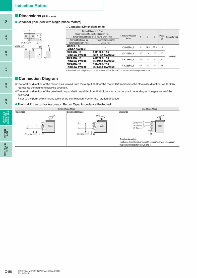
ORIENTAL MOTOR GENERAL CATALOGUE 2012/2013
C-58
Induction Motors
6 W
15 W
25 W
40 W
60 W
90 W
IP65 T
erm
inal
Bo
x T
yp
es
6 W
to 4
0 W
20
0 W
BH
Serie
s2-p
ole
40 W
to 1
50 W
Dimensions ■ (Unit = mm)
Capacitor (Included with single-phase motors) ●
ϕ4.3 20
A
CB+
10B4.
54
10 6AMP#187
Capacitor Dimensions (mm) ◇Product Name and Type
Upper Product Name: Combination TypeLower Product Name in ( ): Round Shaft Type Capacitor Product
NameA B C
Mass(g)
Capacitor CapThermal Protector for Automatic Return Type
Thermal Protector for Signal Type
2IK6EB-□S(2IK6A-CW2BE) − CH06BFAUL 31 14.5 23.5 18
Included
3IK15EB-□S(3IK15A-CW2BE)
3IK15EB-□SS(3IK15A-CW2BSE) CH10BFAUL 37 18 27 27
4IK25EB-□S(4IK25A-CW2BE)
4IK25EB-□SS(4IK25A-CW2BSE) CH15BFAUL 38 21 31 37
5IK40EB-□S(5IK40A-CW2BE)
5IK40EB-□SS(5IK40A-CW2BSE) CH23BFAUL 48 21 31 43
A number indicating the gear ratio is entered where the box ● □ is located within the product name.
Connection Diagram ■
The rotation direction of the motor is as viewed from the output shaft of the motor. CW represents the clockwise direction, while CCW ●represents the counterclockwise direction.The rotation direction of the gearhead output shaft may differ from that of the motor output shaft depending on the gear ratio of the ●gearhead.Refer to the permissible torque table of the combination type for the rotation direction.
Thermal Protector for Automatic Return Type, Impedance Protected ●Single-Phase Motor Three-Phase Motor
Clockwise Counterclockwise Clockwise
CW
U1U2Z2
LN
PE
U1U2Z2
Capacitor
MotorL
N
CCW
PE
U1U2Z2
Motor
Capacitor
UVW
L1 (R)L2 (S)L3 (T)
CW
PE
Motor
CounterclockwiseTo change the rotation direction to counterclockwise, change any two connections between R, S and T.
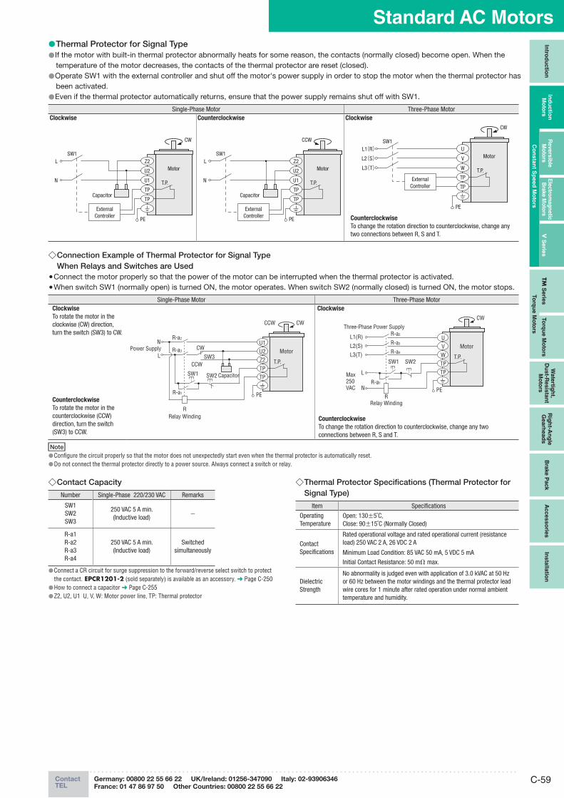
C-59ContactTEL
Germany: 00800 22 55 66 22 UK/Ireland: 01256-347090 Italy: 02-93906346
France: 01 47 86 97 50 Other Countries: 00800 22 55 66 22
Standard AC MotorsIn
trod
uctio
nIn
du
ctio
n
Mo
t ors
Revers
ible
M
oto
rsE
lectro
mag
netic
B
rake M
oto
rsV
Serie
sTM
Serie
sTo
rqu
e M
oto
rs
Wate
rtigh
t, D
ust-R
esis
tan
t M
oto
rs
Rig
ht-A
ng
le
Gearh
ead
sB
rake P
ack
Acc
es
so
ries
Insta
llatio
n
Co
nsta
nt S
peed
Mo
tors
To
rqu
e M
oto
rs
Thermal Protector for Signal Type ●If the motor with built-in thermal protector abnormally heats for some reason, the contacts (normally closed) become open. When the ●temperature of the motor decreases, the contacts of the thermal protector are reset (closed).Operate SW1 with the external controller and shut off the motor's power supply in order to stop the motor when the thermal protector has ●been activated. Even if the thermal protector automatically returns, ensure that the power supply remains shut off with SW1. ●
Single-Phase Motor Three-Phase MotorClockwise Counterclockwise Clockwise
L
N
CW
T.P.
SW1
PE
U1
TP
TP
U2
Z2Motor
Capacitor
ExternalController
L
N
CCW
T.P.
SW1
PE
U1
TP
TP
U2
Z2Motor
Capacitor
ExternalController
L1(R)L2(S)L3(T)
CW
T.P.
SW1
PE
W
TP
TP
V
UMotor
ExternalController
CounterclockwiseTo change the rotation direction to counterclockwise, change any two connections between R, S and T.
Connection Example of Thermal Protector for Signal Type ◇When Relays and Switches are Used
Connect the motor properly so that the power of the motor can be interrupted when the thermal protector is activated. ●When switch SW1 (normally open) is turned ON, the motor operates. When switch SW2 (normally closed) is turned ON, the motor stops. ●
Single-Phase Motor Three-Phase MotorClockwiseTo rotate the motor in the clockwise (CW) direction, turn the switch (SW3) to CW.
CounterclockwiseTo rotate the motor in the counterclockwise (CCW) direction, turn the switch (SW3) to CCW.
SW1
N
LPower Supply
R-a2
R-a3
R-a1
CW
CCWSW3
SW2 Capacitor
Motor
CWCCW
T.P.
PE
Z2TPTP
U2U1
RRelay Winding
Clockw ise
L1(R)
L2(S)L3(T)
SW2
R-a2
R-a3
R-a4
R-a1
Max250VAC
SW1
L
N
Three-Phase Power Supply
RRelay Winding
Motor
CW
T.P.
PE
WTPTP
VU
CounterclockwiseTo change the rotation direction to counterclockwise, change any two connections between R, S and T.
NoteConfigure the circuit properly so that the motor does not unexpectedly start even when the thermal protector is automatically reset. ●Do not connect the thermal protector directly to a power source. Always connect a switch or relay. ●
Contact Capacity ◇Number Single-Phase 220/230 VAC Remarks
SW1SW2SW3
250 VAC 5 A min.(Inductive load)
−
R-a1R-a2R-a3R-a4
250 VAC 5 A min.(Inductive load)
Switched simultaneously
Connect a CR circuit for surge suppression to the forward/reverse select switch to protect ●the contact. EPCR1201-2 (sold separately) is available as an accessory. ➜ Page C-250How to connect a capacitor ● ➜ Page C-255Z2, U2, U1 U, V, W: Motor power line, TP: Thermal protector ●
Thermal Protector Specifications (Thermal Protector for ◇Signal Type)
Item Specifications
Operating Temperature
Open: 130±5˚C,Close: 90±15˚C (Normally Closed)
Contact Specifi cations
Rated operational voltage and rated operational current (resistance load) 250 VAC 2 A, 26 VDC 2 A
Minimum Load Condition: 85 VAC 50 mA, 5 VDC 5 mA
Initial Contact Resistance: 50 mΩ max.
Dielectric Strength
No abnormality is judged even with application of 3.0 kVAC at 50 Hz or 60 Hz between the motor windings and the thermal protector lead wire cores for 1 minute after rated operation under normal ambient temperature and humidity.
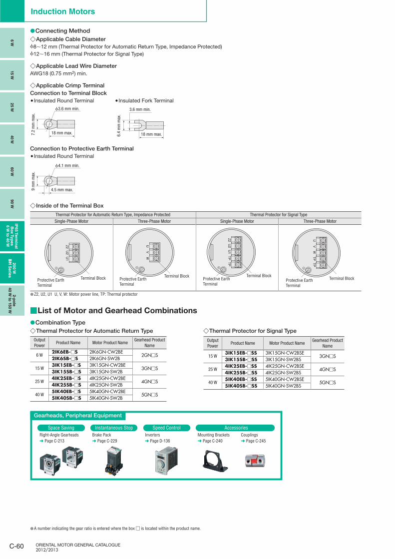
ORIENTAL MOTOR GENERAL CATALOGUE 2012/2013
C-60
Induction Motors
6 W
15 W
25 W
40 W
60 W
90 W
IP65 T
erm
inal
Bo
x T
yp
es
6 W
to 4
0 W
20
0 W
BH
Serie
s2-p
ole
40 W
to 1
50 W
Connecting Method ●Applicable Cable Diameter ◇
ϕ8∼12 mm (Thermal Protector for Automatic Return Type, Impedance Protected)ϕ12∼16 mm (Thermal Protector for Signal Type)
Applicable Lead Wire Diameter ◇AWG18 (0.75 mm2) min.
Applicable Crimp Terminal ◇Connection to Terminal Block
Insulated Round Terminal ●ϕ3.6 mm min.
18 mm max.7.2
mm
max
.
Insulated Fork Terminal ●
18 mm max.6.4
mm
max
.
3.6 mm min.
Connection to Protective Earth TerminalInsulated Round Terminal ●
ϕ4.1 mm min.
4.5 mm max.9 m
m m
ax.
Inside of the Terminal Box ◇Thermal Protector for Automatic Return Type, Impedance Protected Thermal Protector for Signal TypeSingle-Phase Motor Three-Phase Motor Single-Phase Motor Three-Phase Motor
Protective EarthTerminal
Terminal BlockProtective EarthTerminal
Terminal Block
Z2, U2, U1 U, V, W: Motor power line, TP: Thermal protector ●
List of Motor and Gearhead Combinations ■
Combination Type ● Thermal Protector for Automatic Return Type ◇
Output Power
Product Name Motor Product NameGearhead Product
Name
6 W2IK6EB-□S 2IK6GN-CW2BE
2GN□S2IK6SB-□S 2IK6GN-SW2B
15 W3IK15EB-□S 3IK15GN-CW2BE
3GN□S3IK15SB-□S 3IK15GN-SW2B
25 W4IK25EB-□S 4IK25GN-CW2BE
4GN□S4IK25SB-□S 4IK25GN-SW2B
40 W5IK40EB-□S 5IK40GN-CW2BE
5GN□S5IK40SB-□S 5IK40GN-SW2B
Thermal Protector for Signal Type ◇
Output Power
Product Name Motor Product NameGearhead Product
Name
15 W3IK15EB-□SS 3IK15GN-CW2BSE
3GN□S3IK15SB-□SS 3IK15GN-SW2BS
25 W4IK25EB-□SS 4IK25GN-CW2BSE
4GN□S4IK25SB-□SS 4IK25GN-SW2BS
40 W5IK40EB-□SS 5IK40GN-CW2BSE
5GN□S5IK40SB-□SS 5IK40GN-SW2BS
Protective EarthTerminal
Terminal Block Protective EarthTerminal
Terminal Block
Gearheads, Peripheral Equipment
Space Saving Instantaneous Stop Speed Control AccessoriesRight-Angle Gearheads➜ Page C-213
Brake Pack➜ Page C-229
Inverters➜ Page D-136
Mounting Brackets➜ Page C-240
Couplings➜ Page C-245
A number indicating the gear ratio is entered where the box ● □ is located within the product name.
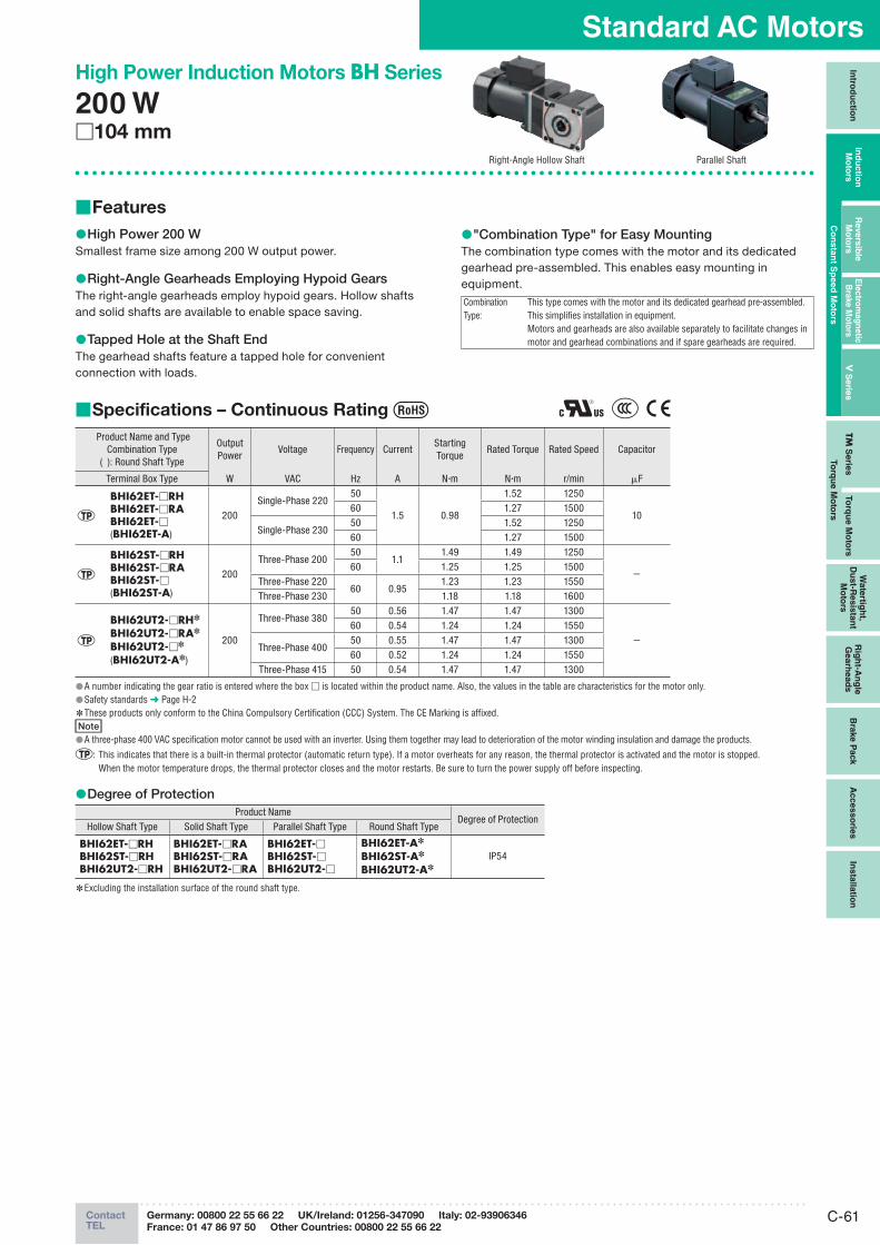
C-61ContactTEL
Germany: 00800 22 55 66 22 UK/Ireland: 01256-347090 Italy: 02-93906346
France: 01 47 86 97 50 Other Countries: 00800 22 55 66 22
Standard AC MotorsIn
trod
uctio
nIn
du
ctio
n
Mo
t ors
Revers
ible
M
oto
rsE
lectro
mag
netic
B
rake M
oto
rsV
Serie
sTM
Serie
sTo
rqu
e M
oto
rs
Wate
rtigh
t, D
ust-R
esis
tan
t M
oto
rs
Rig
ht-A
ng
le
Gearh
ead
sB
rake P
ack
Acc
es
so
ries
Insta
llatio
n
Co
nsta
nt S
peed
Mo
tors
To
rqu
e M
oto
rs
High Power Induction Motors BH Series
200 W □104 mm
Right-Angle Hollow Shaft Parallel Shaft
Features ■
High Power 200 W ●Smallest frame size among 200 W output power.
Right-Angle Gearheads Employing Hypoid Gears ●The right-angle gearheads employ hypoid gears. Hollow shafts and solid shafts are available to enable space saving.
Tapped Hole at the Shaft End ●The gearhead shafts feature a tapped hole for convenient connection with loads.
"Combination Type" for Easy Mounting ●The combination type comes with the motor and its dedicated gearhead pre-assembled. This enables easy mounting in equipment.
Combination Type:
This type comes with the motor and its dedicated gearhead pre-assembled. This simplifies installation in equipment.Motors and gearheads are also available separately to facilitate changes in motor and gearhead combinations and if spare gearheads are required.
Specifications – Continuous Rating ■
Product Name and TypeCombination Type
( ): Round Shaft Type
OutputPower
Voltage Frequency CurrentStarting Torque
Rated Torque Rated Speed Capacitor
Terminal Box Type W VAC Hz A N·m N·m r/min μF
BHI62ET-□RHBHI62ET-□RABHI62ET-□(BHI62ET-A)
200Single-Phase 220
50
1.5 0.98
1.52 1250
1060 1.27 1500
Single-Phase 23050 1.52 125060 1.27 1500
BHI62ST-□RHBHI62ST-□RABHI62ST-□(BHI62ST-A)
200Three-Phase 200
501.1
1.49 1.49 1250
−60 1.25 1.25 1500
Three-Phase 22060 0.95
1.23 1.23 1550Three-Phase 230 1.18 1.18 1600
BHI62UT2-□RH✽
BHI62UT2-□RA✽
BHI62UT2-□✽
(BHI62UT2-A✽)
200
Three-Phase 38050 0.56 1.47 1.47 1300
−60 0.54 1.24 1.24 1550
Three-Phase 40050 0.55 1.47 1.47 130060 0.52 1.24 1.24 1550
Three-Phase 415 50 0.54 1.47 1.47 1300
A number indicating the gear ratio is entered where the box ● □ is located within the product name. Also, the values in the table are characteristics for the motor only.Safety standards ● ➜ Page H-2 These products only conform to the China Compulsory Certification (CCC) System. The CE Marking is affixed. ✽
NoteA three-phase 400 VAC specification motor cannot be used with an inverter. Using them together may lead to deterioration of the motor winding insulation and damage the products. ●
: This indicates that there is a built-in thermal protector (automatic return type). If a motor overheats for any reason, the thermal protector is activated and the motor is stopped. When the motor temperature drops, the thermal protector closes and the motor restarts. Be sure to turn the power supply off before inspecting.
Degree of Protection ●Product Name
Degree of ProtectionHollow Shaft Type Solid Shaft Type Parallel Shaft Type Round Shaft Type
BHI62ET-□RHBHI62ST-□RHBHI62UT2-□RH
BHI62ET-□RABHI62ST-□RABHI62UT2-□RA
BHI62ET-□BHI62ST-□BHI62UT2-□
BHI62ET-A✽
BHI62ST-A✽
BHI62UT2-A✽
IP54
Excluding the installation surface of the round shaft type. ✽
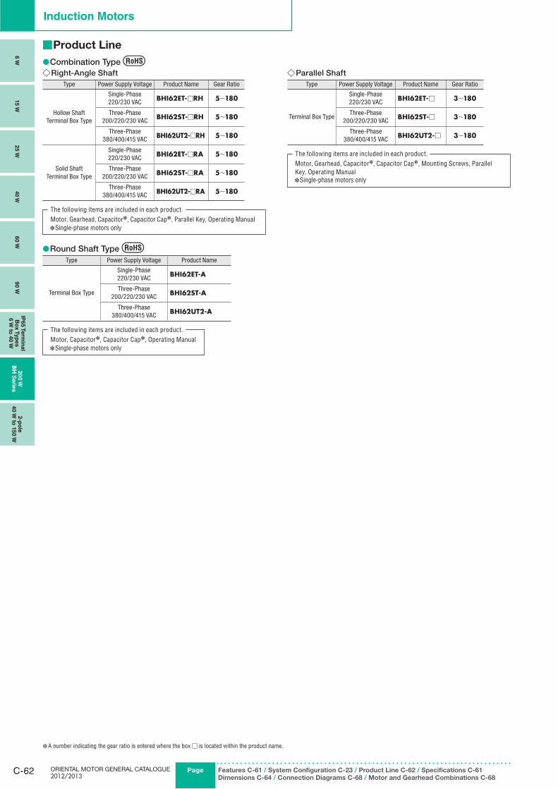
ORIENTAL MOTOR GENERAL CATALOGUE 2012/2013
C-62 Page Features C-61 / System Configuration C-23 / Product Line C-62 / Specifications C-61
Dimensions C-64 / Connection Diagrams C-68 / Motor and Gearhead Combinations C-68
Induction Motors
6 W
15 W
25 W
40 W
60 W
90 W
IP65 T
erm
inal
Bo
x T
yp
es
6 W
to 4
0 W
20
0 W
BH
Serie
s2-p
ole
40 W
to 1
50 W
Product Line ■
Combination Type ●Right-Angle Shaft ◇
Type Power Supply Voltage Product Name Gear Ratio
Hollow ShaftTerminal Box Type
Single-Phase 220/230 VAC BHI62ET-□RH 5∼180
Three-Phase200/220/230 VAC BHI62ST-□RH 5∼180
Three-Phase380/400/415 VAC BHI62UT2-□RH 5∼180
Solid ShaftTerminal Box Type
Single-Phase 220/230 VAC BHI62ET-□RA 5∼180
Three-Phase200/220/230 VAC BHI62ST-□RA 5∼180
Three-Phase380/400/415 VAC BHI62UT2-□RA 5∼180
The following items are included in each product.Motor, Gearhead, Capacitor✽, Capacitor Cap✽, Parallel Key, Operating Manual
Single-phase motors only ✽
Parallel Shaft ◇Type Power Supply Voltage Product Name Gear Ratio
Terminal Box Type
Single-Phase 220/230 VAC BHI62ET-□ 3∼180
Three-Phase200/220/230 VAC BHI62ST-□ 3∼180
Three-Phase380/400/415 VAC BHI62UT2-□ 3∼180
The following items are included in each product.Motor, Gearhead, Capacitor✽, Capacitor Cap✽, Mounting Screws, Parallel Key, Operating Manual
Single-phase motors only ✽
Round Shaft Type ●Type Power Supply Voltage Product Name
Terminal Box Type
Single-Phase 220/230 VAC BHI62ET-A
Three-Phase200/220/230 VAC BHI62ST-A
Three-Phase380/400/415 VAC BHI62UT2-A
The following items are included in each product.Motor, Capacitor✽, Capacitor Cap✽, Operating Manual
Single-phase motors only ✽
A number indicating the gear ratio is entered where the box ● □ is located within the product name.
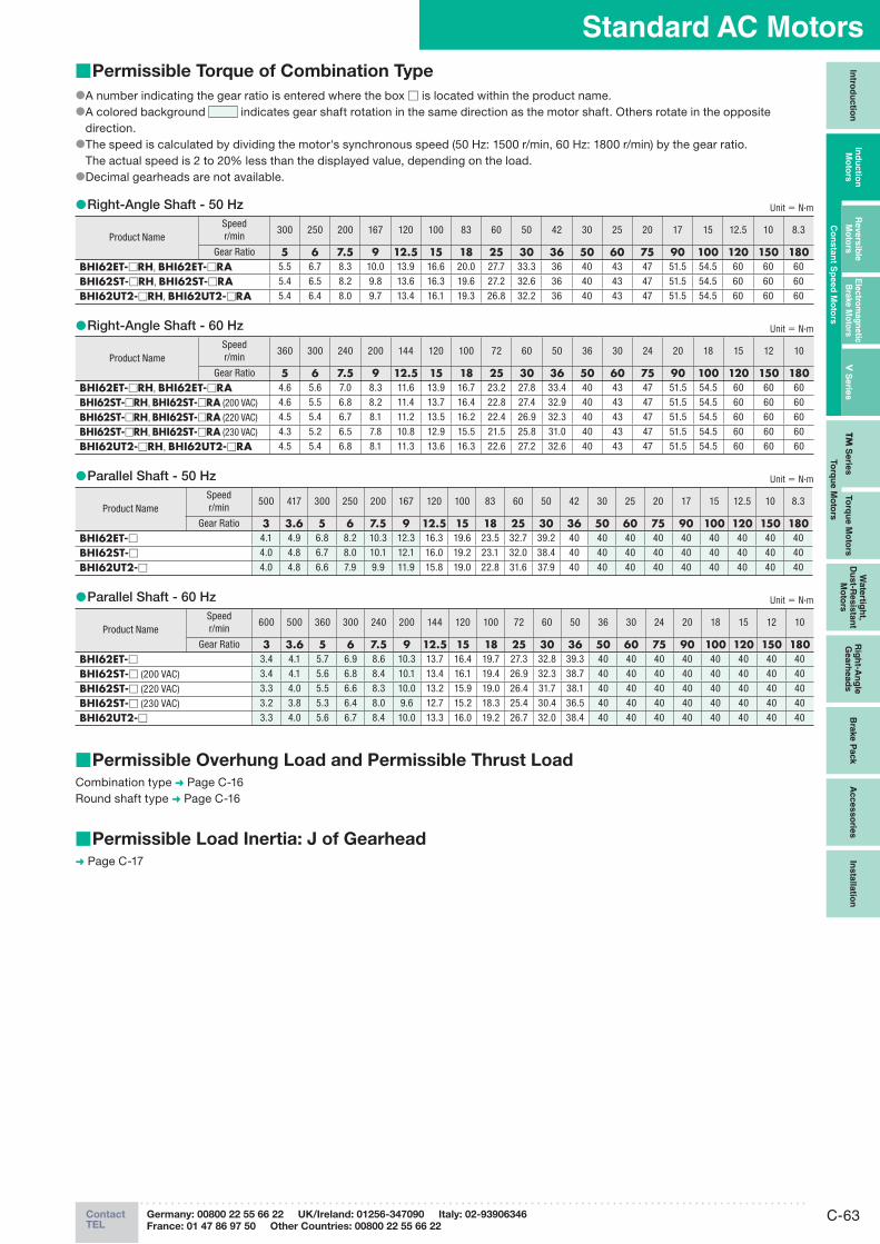
C-63ContactTEL
Germany: 00800 22 55 66 22 UK/Ireland: 01256-347090 Italy: 02-93906346
France: 01 47 86 97 50 Other Countries: 00800 22 55 66 22
Standard AC MotorsIn
trod
uctio
nIn
du
ctio
n
Mo
t ors
Revers
ible
M
oto
rsE
lectro
mag
netic
B
rake M
oto
rsV
Serie
sTM
Serie
sTo
rqu
e M
oto
rs
Wate
rtigh
t, D
ust-R
esis
tan
t M
oto
rs
Rig
ht-A
ng
le
Gearh
ead
sB
rake P
ack
Acc
es
so
ries
Insta
llatio
n
Co
nsta
nt S
peed
Mo
tors
To
rqu
e M
oto
rs
Permissible Torque of Combination Type ■
A number indicating the gear ratio is entered where the box ● □ is located within the product name.A colored background ● indicates gear shaft rotation in the same direction as the motor shaft. Others rotate in the opposite direction.The speed is calculated by dividing the motor's synchronous speed (50 Hz: 1500 r/min, 60 Hz: 1800 r/min) by the gear ratio. ●The actual speed is 2 to 20% less than the displayed value, depending on the load.Decimal gearheads are not available. ●
Right-Angle Shaft - 50 Hz ● Unit = N·m
Product NameSpeedr/min
300 250 200 167 120 100 83 60 50 42 30 25 20 17 15 12.5 10 8.3
Gear Ratio 5 6 7.5 9 12.5 15 18 25 30 36 50 60 75 90 100 120 150 180BHI62ET-□RH, BHI62E T-□RA 5.5 6.7 8.3 10.0 13.9 16.6 20.0 27.7 33.3 36 40 43 47 51.5 54.5 60 60 60
BHI62ST-□RH, BHI62ST-□RA 5.4 6.5 8.2 9.8 13.6 16.3 19.6 27.2 32.6 36 40 43 47 51.5 54.5 60 60 60
BHI62UT2-□RH, BHI62UT2-□RA 5.4 6.4 8.0 9.7 13.4 16.1 19.3 26.8 32.2 36 40 43 47 51.5 54.5 60 60 60
Right-Angle Shaft - 60 Hz ● Unit = N·m
Product NameSpeedr/min
360 300 240 200 144 120 100 72 60 50 36 30 24 20 18 15 12 10
Gear Ratio 5 6 7.5 9 12.5 15 18 25 30 36 50 60 75 90 100 120 150 180BHI62ET-□RH, BHI62E T-□RA 4.6 5.6 7.0 8.3 11.6 13.9 16.7 23.2 27.8 33.4 40 43 47 51.5 54.5 60 60 60
BHI62ST-□RH, BHI62S T-□RA (200 VAC) 4.6 5.5 6.8 8.2 11.4 13.7 16.4 22.8 27.4 32.9 40 43 47 51.5 54.5 60 60 60
BHI62ST-□RH, BHI62S T-□RA (220 VAC) 4.5 5.4 6.7 8.1 11.2 13.5 16.2 22.4 26.9 32.3 40 43 47 51.5 54.5 60 60 60
BHI62ST-□RH, BHI62S T-□RA (230 VAC) 4.3 5.2 6.5 7.8 10.8 12.9 15.5 21.5 25.8 31.0 40 43 47 51.5 54.5 60 60 60
BHI62UT2-□RH, BHI62U T2-□RA 4.5 5.4 6.8 8.1 11.3 13.6 16.3 22.6 27.2 32.6 40 43 47 51.5 54.5 60 60 60
Parallel Shaft - 50 Hz ● Unit = N·m
Product NameSpeedr/min
500 417 300 250 200 167 120 100 83 60 50 42 30 25 20 17 15 12.5 10 8.3
Gear Ratio 3 3.6 5 6 7.5 9 12.5 15 18 25 30 36 50 60 75 90 100 120 150 180BHI62ET-□ 4.1 4.9 6.8 8.2 10.3 12.3 16.3 19.6 23.5 32.7 39.2 40 40 40 40 40 40 40 40 40
BHI62ST-□ 4.0 4.8 6.7 8.0 10.1 12.1 16.0 19.2 23.1 32.0 38.4 40 40 40 40 40 40 40 40 40
BHI62UT2-□ 4.0 4.8 6.6 7.9 9.9 11.9 15.8 19.0 22.8 31.6 37.9 40 40 40 40 40 40 40 40 40
Parallel Shaft - 60 Hz ● Unit = N·m
Product NameSpeedr/min
600 500 360 300 240 200 144 120 100 72 60 50 36 30 24 20 18 15 12 10
Gear Ratio 3 3.6 5 6 7.5 9 12.5 15 18 25 30 36 50 60 75 90 100 120 150 180BHI62ET-□ 3.4 4.1 5.7 6.9 8.6 10.3 13.7 16.4 19.7 27.3 32.8 39.3 40 40 40 40 40 40 40 40
BHI62ST-□ (200 VAC) 3.4 4.1 5.6 6.8 8.4 10.1 13.4 16.1 19.4 26.9 32.3 38.7 40 40 40 40 40 40 40 40
BHI62ST-□ (220 VAC) 3.3 4.0 5.5 6.6 8.3 10.0 13.2 15.9 19.0 26.4 31.7 38.1 40 40 40 40 40 40 40 40
BHI62ST-□ (230 VAC) 3.2 3.8 5.3 6.4 8.0 9.6 12.7 15.2 18.3 25.4 30.4 36.5 40 40 40 40 40 40 40 40
BHI62UT2-□ 3.3 4.0 5.6 6.7 8.4 10.0 13.3 16.0 19.2 26.7 32.0 38.4 40 40 40 40 40 40 40 40
Permissible Overhung Load and Permissible Thrust Load ■Combination type ➜ Page C-16Round shaft type ➜ Page C-16
Permissible Load Inertia: J of Gearhead ■➜ Page C-17
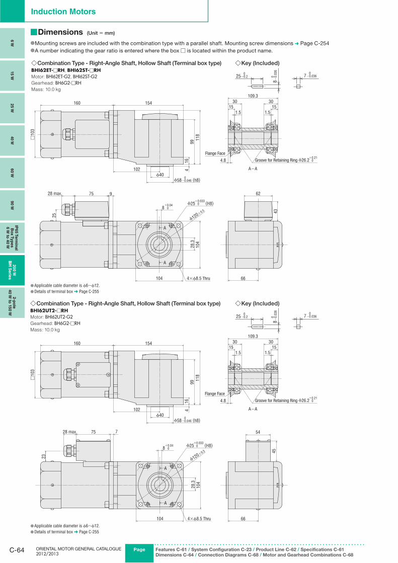
ORIENTAL MOTOR GENERAL CATALOGUE 2012/2013
C-64 Page Features C-61 / System Configuration C-23 / Product Line C-62 / Specifications C-61
Dimensions C-64 / Connection Diagrams C-68 / Motor and Gearhead Combinations C-68
Induction Motors
6 W
15 W
25 W
40 W
60 W
90 W
IP65 T
erm
inal
Bo
x T
yp
es
6 W
to 4
0 W
20
0 W
BH
Serie
s2-p
ole
40 W
to 1
50 W
Dimensions ■ (Unit = mm)
Mounting screws are included with the combination type with a parallel shaft. Mounting screw dimensions ● ➜ Page C-254A number indicating the gear ratio is entered where the box ● □ is located within the product name.
◇Combination Type - Right-Angle Shaft, Hollow Shaft (Terminal box type) BHI62ET-□RH, BHI62ST-□RHMotor: BHI62ET-G2, BHI62ST-G2Gearhead: BH6G2-□RHMass: 10.0 kg
Key (Included) ◇
0
08−
0.03
6
25−0.20
7−0.036
ϕ120±0.5
ϕ25 0 (H8)+0.033
4.8
A−A499
16
118
151.5
30109.3
3015
1.5
160 154
□10
3
102ϕ40
ϕ58−0.046 (h8)0
97528 max.
8 0 +0.04
62
10443
104
28.3
A
A
66
25
+0.21Groove for Retaining Ring ϕ26.2 0
Flange Face
4×ϕ8.5 Thru
Applicable cable diameter is ● ϕ6∼ϕ12.Details of terminal box ● ➜ Page C-255
◇Combination Type - Right-Angle Shaft, Hollow Shaft (Terminal box type)BHI62UT2-□RHMotor: BHI62UT2-G2Gearhead: BH6G2-□RHMass: 10.0 kg
Key (Included) ◇
0
08−
0.03
6
25−0.20
7−0.036
A
A
151.5
30109.3
3015
1.5
4.8
A−A
66104
104
28.3
□10
3
160 154
ϕ40ϕ58−0.046 (h8)0
499
16
118
8 0 +0.04
45
54
102
28 max. 775
23
ϕ25 0 (H8)+0.033
ϕ120±0.5
Groove for Retaining Ring ϕ26.2 0 +0.21
4×ϕ8.5 Thru
Flange Face
Applicable cable diameter is ● ϕ6∼ϕ12.Details of terminal box ● ➜ Page C-255
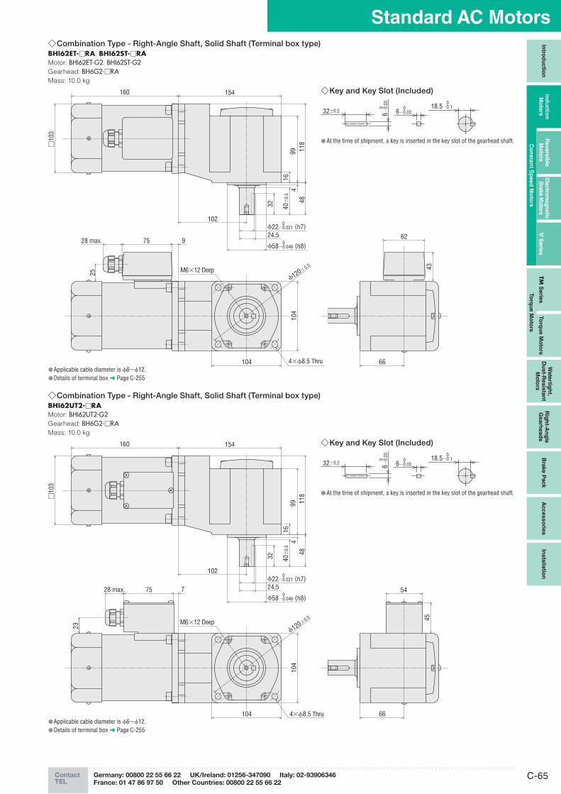
C-65ContactTEL
Germany: 00800 22 55 66 22 UK/Ireland: 01256-347090 Italy: 02-93906346
France: 01 47 86 97 50 Other Countries: 00800 22 55 66 22
Standard AC MotorsIn
trod
uctio
nIn
du
ctio
n
Mo
t ors
Revers
ible
M
oto
rsE
lectro
mag
netic
B
rake M
oto
rsV
Serie
sTM
Serie
sTo
rqu
e M
oto
rs
Wate
rtigh
t, D
ust-R
esis
tan
t M
oto
rs
Rig
ht-A
ng
le
Gearh
ead
sB
rake P
ack
Acc
es
so
ries
Insta
llatio
n
Co
nsta
nt S
peed
Mo
tors
To
rqu
e M
oto
rs
Combination Type - Right-Angle Shaft, Solid Shaft (Terminal box type) ◇BHI62ET-□RA, BHI62ST-□RAMotor: BHI62ET-G2, BHI62ST-G2Gearhead: BH6G2-□RAMass: 10.0 kg
102
24.5ϕ22−0.021 (h7)0
ϕ58−0.046 (h8)0
1699 11
848
40±
0.5
4
154160
□10
3
28 max. 75 9
104
62
104 66
ϕ120±0.5
32
43
25
4×ϕ8.5 Thru
M6×12 Deep
Key and Key Slot (Included) ◇
32±0.2
06−
0.03
06−0.03
018.5−0.1
At the time of shipment, a key is inserted in the key slot of the gearhead shaft. ●
Applicable cable diameter is ● ϕ6∼ϕ12.Details of terminal box ● ➜ Page C-255
Combination Type ◇ - Right-Angle Shaft, Solid Shaft (Terminal box type)BHI62UT2-□RAMotor: BHI62UT2-G2Gearhead: BH6G2-□RAMass: 10.0 kg
28 max. 775
23
104 66
45
54
99 118
48
ϕ22−0.021 (h7)0
416
40±
0.5
154160
□10
3
102
24.5
ϕ58−0.046 (h8)0
32
104
ϕ120±0.5
4×ϕ8.5 Thru
M6×12 Deep
Key and Key Slot (Included) ◇
32±0.2
06−
0.03
06−0.03
018.5−0.1
At the time of shipment, a key is inserted in the key slot of the gearhead shaft. ●
Applicable cable diameter is ● ϕ6∼ϕ12.Details of terminal box ● ➜ Page C-255
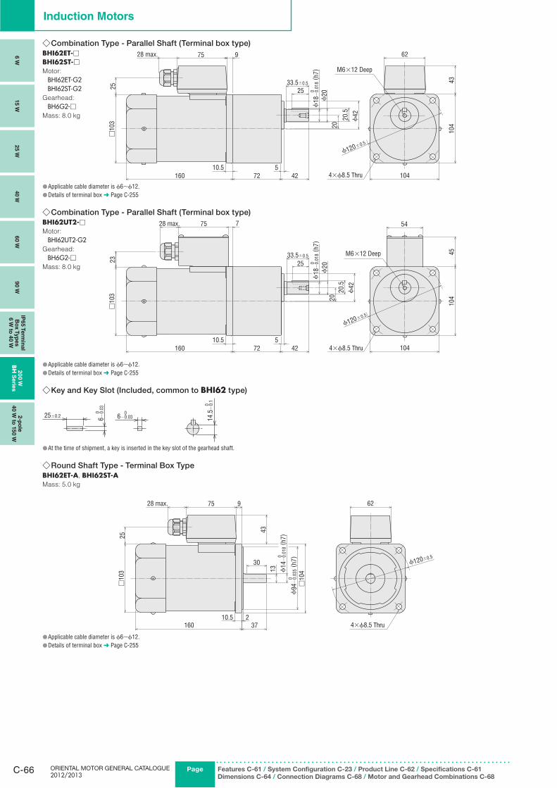
ORIENTAL MOTOR GENERAL CATALOGUE 2012/2013
C-66 Page Features C-61 / System Configuration C-23 / Product Line C-62 / Specifications C-61
Dimensions C-64 / Connection Diagrams C-68 / Motor and Gearhead Combinations C-68
Induction Motors
6 W
15 W
25 W
40 W
60 W
90 W
IP65 T
erm
inal
Bo
x T
yp
es
6 W
to 4
0 W
20
0 W
BH
Serie
s2-p
ole
40 W
to 1
50 W
Combination Type ◇ - Parallel Shaft (Terminal box type) BHI62ET-□ BHI62ST-□Motor:
BHI62ET-G2BHI62ST-G2
Gearhead:
BH6G2-□Mass: 8.0 kg
Applicable cable diameter is ● ϕ6∼ϕ12.Details of terminal box ● ➜ Page C-255
Combination Type - Parallel Shaft (Terminal box type) ◇BHI62UT2-□Motor:
BHI62UT2-G2Gearhead:
BH6G2-□Mass: 8.0 kg
Applicable cable diameter is ● ϕ6∼ϕ12.Details of terminal box ● ➜ Page C-255
Key and Key Slot (Included, common to ◇ BHI62 type)
25±0.2
06−
0.03
06−0.03
014
.5−
0.1
At the time of shipment, a key is inserted in the key slot of the gearhead shaft. ●
Round Shaft Type ◇ - Terminal Box Type BHI62ET-A, BHI62ST-AMass: 5.0 kg
30
43
28 max. 75 9
□10
4
37160210.5
13
□10
3
62
ϕ120±0.5
ϕ14
−0.
018
( h7)
0
ϕ94
−0.
035
( h7)
0
4×ϕ8.5 Thru
25
Applicable cable diameter is ● ϕ6∼ϕ12.Details of terminal box ● ➜ Page C-255
28 max. 75 9
20.5
ϕ18
−0.
018
( h7)
0
20
ϕ42
ϕ20
104
43
62
10410.5 5
72 42160
□10
325 25
33.5±0.5
ϕ120±0.5
M6×12 Deep
4×ϕ8.5 Thru
4510
4
10420
.5ϕ
42
20
□10
3
160 72 42
ϕ18
−0.
018
( h7)
02533.5±0.5
10.5 5
23
28 max. 775 54
ϕ120±0.5
ϕ20
4×ϕ8.5 Thru
M6×12 Deep
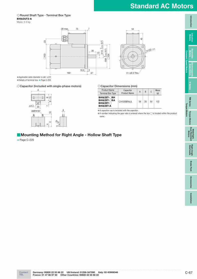
C-67ContactTEL
Germany: 00800 22 55 66 22 UK/Ireland: 01256-347090 Italy: 02-93906346
France: 01 47 86 97 50 Other Countries: 00800 22 55 66 22
Standard AC MotorsIn
trod
uctio
nIn
du
ctio
n
Mo
t ors
Revers
ible
M
oto
rsE
lectro
mag
netic
B
rake M
oto
rsV
Serie
sTM
Serie
sTo
rqu
e M
oto
rs
Wate
rtigh
t, D
ust-R
esis
tan
t M
oto
rs
Rig
ht-A
ng
le
Gearh
ead
sB
rake P
ack
Acc
es
so
ries
Insta
llatio
n
Co
nsta
nt S
peed
Mo
tors
To
rqu
e M
oto
rs
Round Shaft Type ◇ - Terminal Box TypeBHI62UT2-AMass: 5.0 kg
45
ϕ14
−0.
018
( h7)
0
30
13
ϕ94
−0.
035
( h7)
0
□10
4
37210.5
160
28 max. 775
□10
323
54
ϕ120±0.5
4×ϕ8.5 Thru
Applicable cable diameter is ● ϕ6∼ϕ12.Details of terminal box ● ➜ Page C-255
Capacitor (Included with single-phase motors) ◇
6
A
CB
720
10
AMP#187
ϕ4.3
4B+
15
R10
Capacitor Dimensions (mm) ◇Product Name Capacitor
Product NameA B C
Mass(g)Terminal Box Type
BHI62ET-□RHBHI62ET-□RABHI62ET-□BHI62ET-A
CH100BFAUL 58 35 50 132
A capacitor cap is included with the capacitor. ●A number indicating the gear ratio is entered where the box ● □ is located within the product name.
Mounting Method for Right Angle - Hollow Shaft Type ■➜ Page C-220
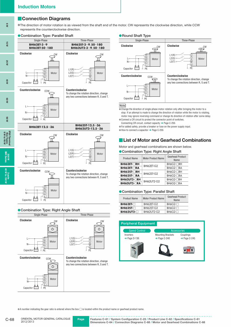
ORIENTAL MOTOR GENERAL CATALOGUE 2012/2013
C-68 Page Features C-61 / System Configuration C-23 / Product Line C-62 / Specifications C-61
Dimensions C-64 / Connection Diagrams C-68 / Motor and Gearhead Combinations C-68
Induction Motors
6 W
15 W
25 W
40 W
60 W
90 W
IP65 T
erm
inal
Bo
x T
yp
es
6 W
to 4
0 W
20
0 W
BH
Serie
s2-p
ole
40 W
to 1
50 W
Connection Diagrams ■
The direction of motor rotation is as viewed from the shaft end of the motor. CW represents the clockwise direction, while CCW ●represents the counterclockwise direction.
Combination Type: Parallel Shaft ●Single-Phase Three-Phase
BHI62ET-3∼9BHI62ET-50∼180
BHI62ST-3∼9, 50∼180BHI62UT2-3∼9, 50∼180
Clockwise
Capacitor
LN
PE
U1U2Z2
CW
Motor
Clockwise
UVW
L1(R)L2(S)L3(T)
PE
CW
Motor
Counterclockwise
L
N
Capacitor PE
U1U2Z2
CCW
Motor
Counterclockwise
To change the rotation direction, change any two connections between R, S and T.
BHI62ET-12.5∼36 BHI62ST-12.5∼36BHI62UT2-12.5∼36
Clockwise
L
N
Capacitor PE
U1U2Z2
CW
Motor
Clockwise
UVW
L1(S)L2(R)L3(T)
PE
CW
Motor
Counterclockwise
Capacitor
LN
PE
U1U2Z2
CCW
Motor
Counterclockwise
To change the rotation direction, change any two connections between R, S and T.
Combination Type: Right Angle Shaft ●Single-Phase Three-Phase
Clockwise
L
N
Capacitor PE
U1U2Z2
CW
Motor
Clockwise
UVW
L1(S)L2(R)L3(T)
PE
CW
Motor
Counterclockwise
Capacitor
LN
PE
U1U2Z2
CCW
Motor
Counterclockwise
To change the rotation direction, change any two connections between R, S and T.
Round Shaft Type ●Single-Phase Three-Phase
Clockwise
U1U2Z2
Capacitor
LN
Motor
CW
PE
U1U2Z2
Clockwise
UVW
L1(R)L2(S)L3(T)
Motor
CW
PE
Counterclockwise
L
NMotor
Capacitor
CCW
PE
U1U2Z2
Counterclockwise
To change the rotation direction, change any two connections between R, S and T.
NoteChange the direction of single-phase motor rotation only after bringing the motor to a ●stop. If an attempt is made to change the direction of rotation while the motor is rotating, motor may ignore reversing command or change its direction of rotation after some delay.Connect a CR circuit to protect the connector point of switches. ●Connecting CR circuit, contact capacity ➜ Page C-255For added safety, provide a breaker or fuse on the power supply input. ●How to connect a capacitor ● ➜ Page C-255
List of Motor and Gearhead Combinations ■
Motor and gearhead combinations are shown below.
Combination Type: Right Angle Shaft ●
Product Name Motor Product NameGearhead Product
Name
BHI62ET-□RHBHI62ET-G2
BH6G2-□RHBHI62ET-□RA BH6G2-□RABHI62ST-□RH
BHI62ST-G2BH6G2-□RH
BHI62ST-□RA BH6G2-□RABHI62UT2-□RH
BHI62UT2-G2BH6G2-□RH
BHI62UT2-□RA BH6G2-□RA
Combination Type: Parallel Shaft ●
Product Name Motor Product NameGearhead Product
Name
BHI62ET-□ BHI62ET-G2 BH6G2-□BHI62ST-□ BHI62ST-G2 BH6G2-□BHI62UT2-□ BHI62UT2-G2 BH6G2-□
Peripheral Equipment
Speed Control AccessoriesInverters➜ Page D-136
Mounting Brackets➜ Page C-240
Couplings➜ Page C-245
A number indicating the gear ratio is entered where the box ● □ is located within the product name or gearhead product name.