motortech product guide en 2015 06
DESCRIPTION
Engine PartsTRANSCRIPT

1
®
Try the alternative.Call the nearest MOTORTECH sales partner for more information.RE
V. 0
6/20
13
Gas Engine Technologyreliable ∙ efficient ∙ worldwide
PRODUCT GUIDE
P/N
01.0
0.00
1-EN
Rev.
06/
2015
GAS ENGINE ACCESSORIES
GAS REGULATION
SENSOR SYSTEMS
GAS ENGINE MANAGEMENT
SPARK PLUGS
IGNITION SYSTEMS

IGNITION CONTROLLERS
Technical Details
General• For 2- and 4-stroke engines• Ignition technology
pulse width modulation • Speed range 20 - 1800 rpm• Max. trigger impulses 16+1• CSA certified,
(Class I, Div. 2, Group C,D; T4)
Technical Data & Functions• 0.1° crankshaft accuracy• Magnetic, Hall effect or
inductive pickup• Multiple timing control vs. - Potentiometer - Speed curve - 0-20 mA analog input - 0-10 V analog input• Multiple energy control vs. MOST
(MOTORTECH Output Stage Technology)
• Programmable firing order• Overspeed shutdown function• Access controlled• Programmable spark duration
• Energy output control• 2 programmable speed curves with
max. 8 speed points (speed/ignition timing)
• Diagnostic memory• System status display• Error memory
Ignition Diagnosis• Run time data• Alarm and error messages• Data logging• Primary, secondary
misfire detection• Cylinder individual high-
voltage calculation (kV)
Interfaces• CAN bus 2.0b interface
(CANopen/SAE J1939 protocol)• RS485 interface (Modbus RTU)• USB 2.0 interface
Inputs• Digital ignition release (start/stop)
• Configurable digital input (GPI)• Digital input for schedule A/B
Outputs• 1 Auxiliary Synchronization Output
(ASO) which can support a detonati-on control system (e.g. DetCon) or fuel injection pump controllers
• 1 multipurpose output (GPO)• Go/NoGo output
Configuration• Using the graphic user interface MICT
(MOTORTECH Intergrated Configurati-on Tool, see page XX)
Scope of Supply• MOTORTECH Intergrated
Configuration Tool• USB cable USB 2.0• Vibration dampers• Ground strap• Fastening material• Operating manual
MOTORTECH IGNITION CONTROLLERMIC3
MOTORTECH IGNITION CONTROLLERMIC4
MOTORTECH IGNITION CONTROLLERMIC5
4

5
1) Please contact your MOTORTECH partner for information on the availability of housing styles.
Gene
ral
Feature MIC3 Series MIC4 Series MIC5 Series
Max. number of ignition outputs 6/12 8/16 20
Max. number of pickups 1, 2 1, 2, 3 1, 2, 3
Power supply 10 – 32 VDC 10 – 32 VDC 18 – 32 VDC
Ambient temperature -40 °C to +60 °C -40 °F to +140 °F
-40 °C to +60 °C (LD) -40 °F to +140°F
-40 °C to +60 °C -40 °F to +140 °F
Outp
ut
Max. primary voltage 250 VDC 250 VDC 250 VDC
Max. energy output 200 mJ (300 mJ boost for start phase)
300 mJ (500 mJ boost for start phase)
500 mJ (700 mJ boost for start phase)
Max. progammable spark duration 100 – 700 µsec 100 – 1000 µsec 100 – 1500 µsec
Hous
ing
Available Housing styles1) Light Duty (LD) Panel Mount (PM),
Light Duty (LD), Heavy Duty (HD) Heavy Duty (HD)
Dimensions 250 mm x 240mm x 89,5 mm 304 mm x 240 mm x 97,5 mm (LD) 371 mm x 240mm x 114,5mm
Protection class IP54 (LD) IP20 (PM), IP54 (LD), IP65 (HD) IP65 (HD)
On engine installation not permitted not permitted not permitted
Number of potentiometers for manual speed adjustment 0 2 (continuous) 2 (continuous)
Input wiring 35-pole, pin (MIL) Terminal strip Terminal strip
Output wiring 17-pole, socket (MIL) 17-pole, socket (MIL) 35-pole, socket (MIL)
Number of status LEDs 5 6 6
Technical Data

6
IGNITION CONTROLLERIGNITION CONTROLLERS
Efficiency-enhanced engines, highly compressed mixtures, as well as the use of a great variety of gas types are putting higher and higher demands on the entire ignition system, including:
• reliable ignition even with weak or fluctuating calorific values of the gas
• compliance with the strictest emission regulations
• avoidance of knocking and misfiring
• reduction of maintenance through longer spark plug runtimes
These requirements can only be met by precision ignition behavi-or and efficient control of the ignition spark. MOTORTECH Output Stage Technology* (MOST) was developed by MOTORTECH for this.
MOST works with the following principles:
• adjustable ignition spark duration with different available ignition voltages
• constant spark intensity via adjusted ignition spark duration
• 200 to 700 mJ of primary energy (device dependent) are
MOTORTECH OUTPUT STAGE TECHNOLOGYMOST
Settings for MOST in MICTThe settings for MOST are made using the MICT configuration software. On the configuration side Timing – Schedule A/B – Energy, you can define different values for the spark duration, spark intensity, breakdown voltage and energy limit for the start phase and normal operation. That way starting difficul-ties of the engine can be caught. Different energy settings for the two schedules A and B support, for example, optimally matched two gas operation. The settings are dependent on the ignition coils that are used, among other things. They must be suitable for MOST and set correctly on the configu-ration side Engine – Ignition Coils. To optimize the energy settings for an engine, the ignition behavior must be observed and analyzed (misfiring, knock behavior, emission values, etc.). The secondary side diagnosis with MICT, among other things, can help here.
1/2
* Angemeldetes Patent
Wirkungsgradgesteigerte Motoren, hochverdichtete Gemische sowie der Einsatz unterschiedlichster Gasarten stellen immer höhere Anforderungen an das gesamte Zündsystem, u. a:
– zuverlässige Zündung auch bei schwachen oder wechselnden Brennwerten des Gases
– Einhaltung von strengsten Emissionsvorschriften
– Vermeidung von Klopfen und Zündaussetzern
– Verringerung der Wartung durch längere Zündkerzenlaufzeiten
Diese Anforderungen können nur durch ein präzises Zündverhalten und durch eine leistungsstarke Steuerung des Zündfunkens erfüllt werden. Hierfür wurde bei MOTORTECH die MOTORTECH Output Stage Technology (MOST) entwickelt.
MOST arbeitet mit folgenden Prinzipien
– Einstellbare Zündfunkenbrenndauer bei unterschiedlichem Hochspannungsangebot
– Konstante Zündfunkenintensität über die eingestellte Zündfunkenbrenndauer
– zur Verfügung stehen 200 bis 700 mJ Primärenergie
In der Grafik werden das Verhalten einer konventionellen Hochspannungskondensatorzündung (HKZ) und einer Zündung mit MOST gegenübergestellt:
Hochspannungskondensatorzündung Die rote Kurve zeigt, dass bei der Zündung ein hoher Spitzenstrom erreicht wird. Danach nimmt der Strom stark ab. Um eine längere Brenndauer zu erzielen, muss die Energiezufuhr erhöht werden. Dies hat einen höher Spitenstrom zur Folge.
MOST *– MOTORTECH OUTPUT STAGE TECHNOLOGY
Capacitor discharge ignition systemThe red curve shows that a high peak current is reached during ignition. Afterwards, the current decreases sharply. To achieve longer spark duration, the energy supply must be increased. The result of this is a higher peak current.
Ignition System with MOSTThe blue curve shows that a lower peak current is reached during ignition with MOST. The current remains at a constant level until the energy supply ends. Thereafter, the current drops. In this case as well, more energy is supplied for a lon-ger spark duration, however the peak current is not increased in the process.
The graphic compares the behavior of a conventional capacitor discharge ignition system (CDI) and ignition system with MOST.
*Patent No.: US 8,893,692 BS

7
MOTORTECH INTEGRATED CONFIGURATION TOOLMICT
The MICT is the graphical user interface for all controllers of the MIC3, MIC4 and MIC5 series. With a Laptop all configu-rations can be done and run time data of the engine can be checked and adjusted.• Language selectable (DE/EN/CN)• Microsoft Windows XP / Vista / 7 compatible• Included Data base offers engine information such as firing
order, firing sequence, number of ignition coils per cylinder and typical number of teeth on flywheel for easy engine configuration
• Print function of a given moment in the operation can be used for external problem analysis, etc.
• Context sensitive online help• Different access levels to avoid accidental misconfigurations
Sample Screens – Configuration
Parameter Set – Configuration VisualisationThe graphic display of the parameter set A and B offers a fast, visual control of the configured values.
Runtime Data – OverviewIn the overview schedule the most important current runtime data such as rpm, ignition timing or system status can be registered at a glance.
Sample Screen – Runtime Data
Parameter Set – Energy SettingsFor start phase and normal operation of the engine, durations at different high voltage levels and ignition spark intensity can be adjusted with the advanced energy settings.
Breakdown VoltageThe MICT offers a lot of real time and detailed infor-mation about the status of each individual ignition output. Important data will be visually prepared, so that any irregularities will stand out easily. For example, secondary voltage will be displayed as bar graph, and the type of misfiring carries a warning light as symbol.

IGNITION CONTROLLERIGNITION CONTROLLERS
0-5 V / 4-20 mA
A
Z
B
X
1
MOTORTECH DETONATION CONTROL SYSTEMDetCon20
24
MOTORTECH ENGINE INFORMATION MONITORPowerView3
MOTORTECH IGNITION CONTROLLERMIC
CAN CAN
24 VDC Power Supply
6
3
3
8
DDC
V5
34
W
7
Y
MOTORTECH IGNITION CONTROLLERMIC
1) in combination with the MIC3 only one crankshaft sensor possible
1)
8
MIC Ignition Controllers – System Overview

9
Required accessories
1 Ignition controller2 Output harness*3 Pickups*4 Trigger pins & magnets alternative5 Trigger disc alternative - Trigger device6 Pickup cable*7 1 ignition coil per cylinder*
8 1 primary lead / high tension lead per ignition coil*Accessories
B Junction boxC AlphaRail – ignition wiring rail*
System enhancementC DetCon20 – detonation contollerD PowerView3 – HMI module
DescriptionV CamshaftW CrankshaftX EngineY CylinderZ Harness to connect the ignition wiring rails
and the junction box * Shielded and unshielded versions available.
3-pickup arrangementfor 4-stroke engines
1) Reset (Crankshaft) Magnetic pickup (holes, pins, teeth, screws)2) Speed (Crankshaft) Magnetic pickup (holes, pins, teeth, screws)3) Camshaft Hall effect pickup
(magnets) alternative
3) Camshaft Inductive pickup
(pins, screws, slots)
1-pickup arrangement for 4-stroke engines 1) Camshaft Hall effect pickup (disc with magnets) alternative
1) Camshaft Inductive pickup (disc with pins, screws, slots)
2-pickup arrangement for 2-stroke engines1) Reset Magnetic pickup
(holes, pins, teeth, screws)2) Speed Magnetic pickup
(holes, pins, teeth, screws)
Explanation
Established Variations for Pickup Arrangement

10
IGNITION CONTROLLERS
MOTORTECH IGNITION CONTROLLERMIC3
Ignition Controllers – Light Duty – MIL Style Connectors
P/N max. Outputs Connector
ConnectorPickup Voltage CSA MOST ASC Equivalent to
Input Output
66.00.310-6 6 MIL Style 35 pole pin 17 pole socket programmable via MICT X X not applicable
66.00.310-12 12 MIL Style 35 pole pin 17 pole socket programmable via MICT X X not applicable
Input Harnesses for Light Duty Ignition Controllers
P/N Description Field Bus Wiring Connector Length Pickup
06.02.034-160 Input harness for P/N 66.00.310-6/-12 CAN Bus/Modbus 35 pole socket, 180° 160 in. inductive
06.02.036-160 Input harness for P/N 66.00.310-6/-12 CAN Bus/Modbus 35 pole socket, 180° 160 in. Hall effect
Output Harnesses for Light Duty Ignition Controllers1)
P/N Description Connector Length Equivalent to
95.40.217-L Output harness for P/N 66.00.310-6/-12 17 pole pin, 180° "L"= 5/15/25/50 ft. 1) For CSA applications flex conduit has to be ordered separately or supplied by customer.
Junction Box
P/N Description
06.05.075 Junction box
MOST

11
Ignition Controllers – Light Duty – MIL Style Connectors
Connector
P/N max. Outputs Connector Input Output Pickup Voltage CSA MOST ASC Equivalent to
66.00.410-8 8 MIL Style Terminal strip 17 pole socket programmable via MICT x x not applicable
66.00.410-16 16 MIL Style Terminal strip 17 pole socket programmable via MICT x x not applicable
MOST
Output Harnesses for Light Duty and Heavy Duty Ignition Controllers1)
P/N Description Connector Length Equivalent to
95.40.217-L Output harness for P/N 66.00.410-8/-16 and P/N 66.00.440-8/-16 17 pole pin, 180° "L"= 5/15/25/50 ft.1) For CSA applications flex conduit has to be ordered separately or supplied by customer.
Junction Box
P/N Description
06.05.075 Junction box
Ignition Controllers – Panel Mount – Plug Connector Style
Connector
P/N max. Outputs Connector Input Output Pickup Voltage CSA MOST ASC Equivalent to
66.00.400-8 8 Terminal strip Terminal strip Terminal strip programmable via MICT x x not applicable
66.00.400-16 16 Terminal strip Terminal strip Terminal strip programmable via MICT x x not applicable
MOST
Ignition Controllers – Heavy Duty – MIL Style Connector
Connector
P/N max. Outputs Connector Input Output Pickup Voltage CSA MOST ASC Equivalent to
66.00.440-8 8 MIL Style Terminal strip 17 pole socket programmable via MICT x x not applicable
66.00.440-16 16 MIL Style Terminal strip 17 pole socket programmable via MICT x x not applicable
MOST
MOTORTECH IGNITION CONTROLLERMIC4
back
“LD” (Light Duty) “PM” (Panel Mount) “HD” (Heavy Duty)

12
IGNITION CONTROLLERS
MOTORTECH IGNITION CONTROLLERMIC5
Ignition Controllers – Heavy Duty – MIL Style Connectors
P/N max. Outputs Connector
ConnectorPickup Voltage CSA MOST ASC Equivalent to
Input Output
66.00.540-20 20 MIL Style 35 pole socket programmable via MICT X X not applicable
66.00.541-20 20 MIL Style 35 pole pin 35 pole socket programmable via MICT X X not applicable
Input Harnesses for Heavy Duty Ignition Controllers
P/N Description Field Bus Wiring Connector Length Pickup
06.02.034-160 Input harness for P/N 66.00.541-20 CAN Bus/Modbus 35 pole socket, 180° 160 in. inductive
06.02.036-160 Input harness for P/N 66.00.541-20 CAN Bus/Modbus 35 pole socket, 180° 160 in. Hall effect
Output Harnesses for Heavy Duty Ignition Controllers1)
P/N Description Connector Length Equivalent to
95.40.235-L Output harness for P/N 66.00.540-20 and P/N 66.00.541-20 17 pole pin, 180° "L"= 5/15/25/50 ft. 1) For CSA applications flex conduit has to be ordered separately or supplied by customer.
Ignition Controllers – Heavy Duty – MIL Style Connectors
P/N max. Outputs Connector
ConnectorPickup Voltage CSA MOST ASC Equivalent to
Input Output
66.00.542-20 20 MIL Style 14/17 pole socket
programmable via MICT X X not applicable WOODWARD® IC9xx, MIC850
P/N 66.00.851-24/-24-D
Output Harnesses for Heavy Duty Ignition Controllers1)
P/N Description Connector Length Equivalent to
95.40.214-L Output harness for P/N 66.00.542-20 14 pole pin, 180° "L"= 5/15/25/50 ft.
95.40.217-L Output harness for P/N 66.00.542-20 17 pole pin, 180° "L"= 5/15/25/50 ft. 1) For CSA applications flex conduit has to be ordered separately or supplied by customer.
Junction Box
P/N Description
06.05.075 Junction box
MOST

13
MOTORTECH ENGINE INFORMATION MONITORPowerView3The operating data of MIC3, MIC4 and MIC5 series ignition controllers will be completely visualized via HMI module (Human Machine Interface). The overview sheet shows the relevant information as engine speed, ignition timing and status of pickups, ignition outputs or active parameter set.The PowerView3 also allows justification of various ignition parameters such as ignition timing and energy. Functions as the selftest for error diagnostics can also be executed via HMI module. The control keys guarantee simple navigation through different display pages and menus. All in all the PowerView3 HMI module is also able to provide error diag-nostics on-site without requiring a laptop!
The PowerView3 is also available for data visualization of: • Detonation control (DetCon)• Temperature monitoring (available soon)
Sample Screens
MIC OverviewScreen shows the most important operating data of the connected ignition controller.
IgnitionMisfiring and estimated secondary voltage of each individual cylinder will be shown.
Secondary Voltages RecordingVisualization of secondary voltage trend data.
PowerView3 HMI Module
P/N Description
06.05.085 PowerView3 HMI module
06.05.086-F PowerView3 activation code for visualization of MIC3/MIC4/MIC5 data1)
06.05.086-U PowerView3 activation code for visualization of MIC3/MIC4/MIC5 data2)
1) Activation code has to be ordered separately with each PowerView3 HMI module. 2) Only available for upgrade of existing PowerView3 HMI module in the field.

14
IGNITION CONTROLLERS
MOTORTECH ONE CYLINDER IGNITION SYSTEMMOT601
MOT601 Series CD Ignition System – Ignition Kit for Single Cylinder Engines
P/N Figure Description Equivalent to
MOT601 1 MOT601 ignition kit for single cylinder enginesAEI® FM601ARROW® SFI-KITMURPHY® 601 CD Ignition System
MOT601 Series CD Ignition System – Parts for MOT601 Series
P/N Figure Description Equivalent to
M-400A-8814 2 Electronic ignition moduleAEI® 400A-8814ARROW® A400A-8814MURPHY® 72-00-0024
M-260D-8810 3 Charging generatorAEI® 260D-8810ARROW® A260D-8810MURPHY® 72-00-0025
M-270A-8817 4 Magnetic pickup harness
AEI® 270A-8817ARROW® A400A-8817MURPHY® 72-00-0026
M-400A-8813 5 Magnetic charging barAEI® 400A-8813ARROW® A400A-8813MURPHY® 72-00-0027
M-400A-8811 6 Magnetic trigger barAEI® 400A-8811ARROW® A400A-8811MURPHY® 72-00-0028
06.50.055 7 Ignition coil AEI® 1187ARROW® 330-2-AI-46MURPHY® 72-70-0235
1 2 3 4 5 6 7

15
NOTES

16
MOTORTECH offers a wide range of modern high energy ignition coils to fit the following ignition systems:
∙ MIC3
∙ MIC4
∙ MIC5
∙ MIC500
∙ MIC850
IGNITION COILS
MOTORTECH IGNITION COILSMotCoils
New MOTORTECH Style
P/N Color Primary Termination HV Termination Polarity ASC MOST Equivalent to
06.50.100 red #10-32 UNF studs M6 (-) ground x x
06.50.102 red #10-32 UNF studs female (-) ground x x
06.50.104 blue #10-32 UNF studs M6 (-) ground not applicable x
06.50.105 blue #10-32 UNF studs female (-) ground not applicable x
06.50.300 blue #10-32 UNF studs M6 (-) ground not applicable x
06.50.301 blue #10-32 UNF studs female (-) ground not applicable x
MIC3/MIC4/MIC5 with MOST * – MOTORTECH Output Stage Technology ∙ Adjustable spark duration and intensity
∙ Constant spark intensity via adjusted duration
* Patented Technology US 8,893,692 BS
MOTORTECH OUTPUT STAGE TECHNOLOGYMOST MOST
CDI100
50
100 200 300 400 500 600 700 800
variable
varia
ble
Seco
ndar
y Cur
rent
[mA]
spark duration
NON-SHIELDED
M6 connection Female connection

17
Below charts are common industrial ignition coils made for specific ignition systems or to replace other brands.
P/N Color Primary Termination HV Termination Polarity ASC MOST Equivalent to
06.50.053 black #10-32 UNF studs female (+) ground not applicable not applicable 291001,1215 3964
06.50.054 red #10-32 UNF studs female (-) ground not applicable not applicable591010,69694B,4W5439
06.50.055 blue #10-32 UNF studs female (-) ground not applicable not applicable
501061,69694,2W3747,1215 3965
06.50.065 black #10-32 UNF studs female (-) ground not applicable x
MOTORTECH Style
P/N Supersedes Color Primary Termination HV Termination Polarity ASC MOST Equivalent to
06.50.001 consult factory black #10-32 UNF studs female (-) ground not applicable not applicable PPT2477P
06.50.002 06.50.001 black #10-32 UNF studs female (-) ground not applicable not applicable PPT2477L
06.50.003 06.50.007 black #10-32 UNF studs M6 (-) ground x not applicable
06.50.060 black #10-32 UNF studs M6 (-) ground not applicable not applicable
Thousands of smaller gas engines (including CUMMINS®) are equipped with low cost ignition controllers like ALTRONIC® CD1 or CD200 series that use this compact coil. MOTORTECH offers an alternative.
For existing installations with ALTRONIC® ignition coils, MOTORTECH offers a series of replacement products. The ignition coils are designed to have the same characteristics in regards of standard and extended duration as well as the elec-trical characteristics to function with the ALTRONIC® patented “Spark Reference“ high voltage indication system.See chart below for cross reference numbers.
P/N Supersedes Color Primary Termination HV Termination Polarity ASC MOST Equivalent to
06.50.103 black #10-32 UNF studs male (-) ground not applicable not applicable 591040, 3394578
ALTRONIC® Style

18
IGNITION COILS
The rising demand for specialized ignition coils has led MOTORTECH to the decision to design a new series of ignition coils, specially made for use with CATERPILLAR® gas engines.• Compatible with original ignition coils• Support CATERPILLAR® ignition systems• Made in Europe
For CATERPILLAR® G3400 & G3500 Series Gas Engines (Non CSA Applications)
P/N Color Primary Termination HV Termination Polarity ASC MOST Equivalent to
06.50.141 white DEUTSCH® connector female (-) ground not applicable not applicable 232-6348, 165-1591, 131-3277, 129-8802, 108-0615
06.50.1451) white DEUTSCH® connector female (-) ground not applicable x 232-6348, 165-1591, 131-3277, 129-8802, 108-0615
06.50.143 white DEUTSCH® connector female (-) ground not applicable not applicable 232-6352, 213-7443
06.50.1471) white DEUTSCH® connector female (-) ground not applicable x 232-6352, 213-7443
06.50.151 white DEUTSCH® connector female (-) ground not applicable not applicable 232-6346, 165-1589, 124-0749
06.50.1551) white DEUTSCH® connector female (-) ground not applicable x 232-6346, 165-1589, 124-0749
06.50.153 white DEUTSCH® connector female (-) ground not applicable not applicable 232-6350
06.50.1571) white DEUTSCH® connector female (-) ground not applicable x 232-63501) Ignition coils only for use with MIC3, MIC4 or MIC5 ignition controllers.
MOTORTECH IGNITION COILSMotCoils
For CATERPILLAR® G3400 & G3500 Series Gas Engines (CSA Applications)P/N Color Primary Termination HV Termination Polarity ASC MOST Equivalent to
06.50.142 white DEUTSCH® connector female (-) ground not applicable not applicable 232-6349, 165-1592, 122-8070
06.50.1461) white DEUTSCH® connector female (-) ground not applicable x 232-6349, 165-1592, 122-8070
06.50.144 white DEUTSCH® connector female (-) ground not applicable not applicable 232-6353, 213-7444
06.50.1481) white DEUTSCH® connector female (-) ground not applicable x 232-6353, 213-7444
06.50.152 white DEUTSCH® connector female (-) ground not applicable not applicable 232-6347, 165-1590
06.50.1561) white DEUTSCH® connector female (-) ground not applicable x 232-6347, 165-1590
06.50.154 white DEUTSCH® connector female (-) ground not applicable not applicable 259-2078
06.50.1581) white DEUTSCH® connector female (-) ground not applicable x 259-20781) Ignition coils only for use with MIC3, MIC4 and MIC5 ignition controllers.

19
Repair Kits for MOTORTECH Ignition Coils1) – For CATERPILLAR® G3400 and G3500 Series Gas EnginesP/N Description Fits Ignition Coil P/N Extension Length Extension Diameter
06.80.741 Ignition coil repair kit 06.50.141/06.50.145 95 mm 30 mm
06.80.742 Ignition coil repair kit 06.50.142/06.50.146 97 mm 30 mm
06.80.743 Ignition coil repair kit 06.50.143/06.50.147 107 mm 30 mm
06.80.744 Ignition coil repair kit 06.50.144/06.50.148 109 mm 30 mm
06.80.751 Ignition coil repair kit 06.50.151/06.50.155 118 mm 30 mm
06.80.752 Ignition coil repair kit 06.50.152/06.50.156 105 mm 30 mm
06.80.753 Ignition coil repair kit 06.50.153/06.50.157 112 mm 30 mm
06.80.754 Ignition coil repair kit 06.50.154/06.50.158 105 mm 30 mm1) For suitable repair kits for CATERPILLAR® ignition coils, please refer to page xxx.
Ignition Coil Conversion Kits for CUMMINS® Gas Engines
P/N Description
75.30.143Ignition coil conversion kit for CUMMINS® QSK60GIncludes: flange ignition coil with diagnostic interface, adaptor flange with fastening material, spark plug extension
75.30.144Ignition coil conversion kit for CUMMINS® QSV81G/QSV91GIncludes: flange ignition coil with diagnostic interface, adaptor flange with fastening material, spark plug extension
For primary lead options, please refer to page xxx.
For CATERPILLAR® G3520C & G3600 Series (Non CSA Applications), with Spark Plug ExtensionP/N Supersedes Color Primary Termination HV Termination Polarity ASC MOST Equivalent to
06.50.163 06.50.161 white MIL Style 3 pole pin female (-) ground not applicable not applicable 310-3180
06.50.1651) 06.50.162 white MIL Style 3 pole pin female (-) ground not applicable x 310-31801) Ignition coils only for use with MIC3, MIC4 and MIC5 ignition controllers.
For CATERPILLAR® G3520C & G3600 Series (Non CSA Applications), Ignition Coil onlyP/N Color Primary Termination HV Termination Polarity ASC MOST Equivalent to
06.50.164 white MIL Style 3 pole pin female (-) ground not applicable not applicable 283-5270
06.50.1661) white MIL Style 3 pole pin female (-) ground not applicable x 283-52701) Ignition coils only for use with MIC3, MIC4 and MIC5 ignition controllers.
Spark Plug Extension for MOTORTECH Ignition Coils - For CATERPILLAR® G3520C and G3600 Series Gas EnginesP/N Description Resistance Fits Ignition Coil P/N Extension Length Extension Diameter
06.80.600 Spark plug extension 0 kΩ 06.50.164/06.50.166 252 mm 26 mm1) For suitable spark plug extension for CATERPILLAR® ignition coils, please refer to page xxx.
For Perkins® 4016-E61TRS Gas Engines (Non CSA Applications)P/N Color Primary Termination HV Termination Polarity ASC MOST Equivalent to
06.50.111 white DEUTSCH® connector female (-) ground not applicable not applicable 837/9, 10000-06176

20
IGNITION COILS
Boots for MOTORTECH Ignition Coils
P/N FigureIgnition Coil Side Outlet Ignition Coil 06.50. ...
Primary Secondary 90 ° 180 ° 003 053 054 055 060 065 100 102 103 104 105 300 301
06.80.037 1 x x x x x x x x
06.84.082 2 x x x x x x x x
06.84.021 3 x x x1)
06.80.005 4 x x x x x x x x
06.84.083 5 x x x x x
06.80.006 6 x x x x
06.84.006 7 x x x x x x x x x1) Two boots needed for each ignition coil.
Different ignition coil styles require different boots to seal the primary or secondary terminals. MOTORTECH boots are all made from highest grade of silicone (482 °F / 250 °C).
The boots will remain soft and flexible over a long time and protect the operator from touching any low or high voltage terminations. The boots also ensure that the critical areas stay clean and dry even in the worst environment.
Boots for ALTRONIC® Ignition Coils
P/N FigureIgnition Coil Side Outlet
Ignition CoilPrimary Secondary 90 ° 180 °
06.80.037 1 x x 291001 / 591010 / 501061
06.80.036 2 x x 291001 / 591010 / 501061
06.84.006 3 x x 291001 / 591010 / 501061
1 2 3 4 5
1 2
6 7
Accessories
3

21
Secondary Connections
P/N Figure DescriptionIgnition Coil 06.50. ...
003 053 054 055 060 065 100 102 103 104 105 300 301
06.80.261 1 Coil terminal, 180°, requires p/n 06.80.126 x x x x x x x
06.80.091 2 Coil terminal, 180°, requires P/N 06.80.126 x1) x x1) x1)
06.80.108 3 Crimp terminal base x x x x x
06.80.116 4 Crimp terminal, 90°, requires P/N 06.80.108 x x
06.80.116-180 5 Crimp terminal, 180°, requires P/N 06.80.108 x x x
06.80.126 6 Crimp terminal base x x x x x1) x x x1) x x1) x
06.84.024 7 Coil terminal, 90°, including terminal P/N 02.85.920 x
06.84.025 8 Coil terminal, 180°, including terminal P/N 02.85.920 x
22.80.009 9 Coil terminal, 90°, 1 kΩ resistor, requires P/N 06.80.126 x x x1) When using SAE contact pin P/N 06.51.223.
1 2 3 4 5 6 7 8 9
Accessories
P/N Figure DescriptionIgnition Coil 06.50. ...
003 053 054 055 060 065 100 102 103 104 105 300 301
06.51.223 1 SAE contact pin x x x
06.90.2641) 2 Accessory kit incl. fastening screws and nuts x x x x x x
02.85.1012 3 SAE spreading adaptor x x x x x x x1) Comes with each New MOTORTECH Style ignition coil.
1 2 3

22
MOTORTECH makes available the BLUE and RED flanged ignition coil as a replacement for the existing products sold by ALTRONIC® and the engine manufacturers.
Flange Versions
P/N Color Primary Termination HV Termination Polarity ASC MOST Equivalent to
06.50.034 red MIL Style 3 pole pin female (-) ground not applicable not applicable591012,69694F,7W4377
06.50.035 blue MIL Style 3 pole pin female (-) ground not applicable not applicable 591018,(A)69694G
06.50.036 red MIL Style 3 pole pin female (-) ground x x
95.09.100 steel MIL Style 3 pole pin female (-) ground x x
95.09.133 steel MIL Style 3 pole pin female (+) ground not applicable not applicable
95.09.134 steel MIL Style 3 pole pin female (-) ground not applicable not applicable591012,69694F,7W4377
95.09.135 steel MIL Style 3 pole pin female (-) ground not applicable not applicable 591018/(A)69694G
IGNITION COILS
SHIELDED

23
Flange Versions with Diagnostic Interface
P/N Color Primary Termination HV Termination Polarity ASC MOST Equivalent to
95.09.150 steel MIL Style 3 pole pin female (-) ground x x
95.09.153 steel MIL Style 3 pole pin female (+) ground not applicable not applicable
95.09.1541) steel MIL Style 3 pole pin female (-) ground not applicable not applicable591012,69694F,7W4377
95.09.1552) steel MIL Style 3 pole pin female (-) ground not applicable not applicable 591018,(A)69694G
95.09.1563) steel MIL Style 3 pole pin female (-) ground x x
1) Same coil winding as P/N 95.09.134, but with diagnostic interface. Thus also equivalent to P/N 591012, 69694F and 7W4377. 2) Same coil winding as P/N 06.50.035 / 95.09.135, but with diagnostic interface. Thus also equivalent to P/N 591018 and 69694G / A69694G.3) Use of ignition coil only possible, if conversion kits P/N 75.30.143 or 75.30.144 previously were used.
MOTORTECH HIGH VOLTAGE INDICATORSparkView
MOTORTECH flanged ignition coils with diagnostic interface are designed for operators who want to monitor their high voltage traces in a simple way. Measuring high voltage peak (kV) and spark duration (μsec) of all cylinders of an engine with flange coils regularly, will allow easy maintenance of the equipment.
With a MOTORTECH SparkView or digital Scope Meter the operator can receive real time data.
See page xxx.
Additional BNC connector for high voltage measurement
The SparkView is a handheld device developed by MOTORTECH that can monitor the high voltage required by the spark plug while the engine is running. With a measuring clamp or cable and the display for up to 40 kV, it is easy to determine the condition of the spark plugs and the time at which they need to be replaced.

24
IGNITION COILS
Shielded – externally mounted – ignition coils are encapsu-lated in a steel housing with welded lids. A bracket is used to install the coils on a wiring rail or directly on the engine. This type of ignition coil is connected to the shielded spark plug by a braided high tension lead with a 3/4 in. or 1 in. termination. Primary voltage connection is made by a 2 or 3 pole military style screw connector. All parts meet the CSA Class I, Division 2, Group C/D.
Externally Mounted P/N Supersedes Color Primary Termination HV Termination Polarity ASC MOST Equivalent to
95.09.005 steel MIL Style 3 pole pin 3/4-20 UNEF (-) ground x x
95.09.053 95.09.001 steel MIL Style 3 pole pin 3/4-20 UNEF (+) ground not applicable not applicable 291001-S
95.09.054 95.09.003 steel MIL Style 3 pole pin 3/4-20 UNEF (-) ground not applicable not applicable 591010-S
95.09.055 95.09.002 steel MIL Style 3 pole pin 3/4-20 UNEF (-) ground not applicable not applicable 501061-S,2881178
95.08.003 95.08.001/95.08.002 steel MIL Style 2 pole pin 1-20 UNEF (-) ground x x PPT2477AD/
ADL
95.08.005 steel MIL Style 2 pole pin 3/4-20 UNEF (+) ground not applicable not applicable 10-382040-1

25
CSA Certified Ignition Coils – Integral Standard Versions Integral ignition coils are designed to be mounted directly on a dual threaded spark plug. No spark plug lead is required. These ignition coils are mostly used in hazardous applica-tions. Coil life is effected by the temperature that is transfer-red into the coil by the spark plug. On occasions where the spark plug leaks high combustion pressure enters the ignition coil and forces the base coil to blow out of its housing. MOTORTECH has designed a top cover safety ring that will not allow this to happen.
Integral Standard Versions – 3 Pole Primary Connector Arrangement – ALTRONIC® Compatible
P/N1) Supersedes Color Length Primary Termi-nation
HV TerminationPolarity ASC MOST Equivalent to
Outer Thread Inner Thread
95.09.022-6 95.09.012-6,95.09.040-6 steel 5.78 in. MIL Style 3 pole pin 13/16-20
UNEF (-) ground not applicable not applicable 591011A,107-2400
95.09.022-12 95.09.012-12,95.09.040-12 steel 12.15 in. MIL Style 3 pole pin 13/16-20
UNEF (-) ground not applicable not applicable
591011B,591011C,215-2434,69694D
95.09.023-6 95.09.010,95.09.030 steel 5.82 in. MIL Style 3 pole pin 1-20
UNEF13/16-20 UNEF (-) ground not applicable not applicable
591007,4W4959,60615F
95.09.033-6 95.09.011,95.09.031 steel 5.82 in. MIL Style 3 pole pin 1-20
UNEF13/16-20 UNEF (+) ground not applicable not applicable 591008
1) Ignition coils in 10 in. only available on special request.
Integral Standard Versions – 2 Pole Primary Connector Arrangement
P/N1) Supersedes Color Length Primary Termi-nation
HV TerminationPolarity ASC MOST Equivalent to
Outer Thread Inner Thread
95.08.022-6 95.08.010-6,95.08.030-6 steel 5.78 in. MIL Style 2 pole pin 13/16-20
UNEF (-) ground not applicable not applicable PPT2477AA6
95.08.022-12 95.08.010-12,95.08.030-10 steel 12.15 in. MIL Style 2 pole pin 13/16-20
UNEF (-) ground not applicable not applicable PPT2477AA12
1) Ignition coils in 8 in. and 10 in. only available on special request.
HEX for easy installation/deinstallation

26
Integral ignition coils are encapsulated in a steel housing to meet CSA requirements. For slow and mid speed engines it is favorable to have more spark energy available. MOTORTECH has a full line of these special coils with 3-pin primary connector for use with MOTORTECH MIC500, MIC850, MIC3, MIC4 and MIC5 series ignition controllers (includes support of ASC and MOST) available in different length to meet the application and spark plug requirement. Safety First!
Conversion: 1 inch = 25,4 mm / 1 foot = 0,3 m
Integral High Energy Versions – 3 Pole Primary Connector Arrangement
P/N1) Supersedes Color Length Primary Termination
HV TerminationPolarity ASC MOST Equivalent to
Outer Thread Inner Thread
95.09.142-112) 95.09.060-11 steel 11.00 in. MIL Style 3 pole pin 13/16-20 UNEF (-) ground x x
95.09.143-6 95.09.013-6,95.09.050-6 steel 5.50 in. MIL Style 3 pole pin 1-20 UNEF 13/16-20
UNEF (-) ground x x
1) Ignition coils in 12 in. and 14.5 in. only available on special request.2) For use on WAUKESHA® VHP-GSI with rain shield.
Integral High Energy Versions – 3 Pole Primary Connector Arrangement – ALTRONIC® Compatible
P/N1) Supersedes Color Length Primary Termination
HV TerminationPolarity ASC MOST Equivalent
toOuter Thread Inner Thread
95.09.122-112) 95.09.061-11 steel 11.00 in. MIL Style 3 pole pin 13/16-20 UNEF (-) ground not applicable not applicable
95.09.123-6 95.09.051-6 steel 5.50 in. MIL Style 3 pole pin 1-20 UNEF 13/16-20 UNEF (-) ground not applicable not applicable
1) Ignition coils in 12 in. and 14.5 in. only available on special request.2) For use on WAUKESHA® VHP-GSI with rain shield.
For existing installations with ALTRONIC® ignition controllers, MOTORTECH offers a special series of high energy integral ignition coils with 3-pin primary connector. The ignition coils
are designed to have the electrical characteristics to function with the ALTRONIC® patented “Spark Reference“ high voltage indication system.
IGNITION COILS

27
Integral High Energy Version – 2 Pin Primary Connector Arrangement
P/N1) Supersedes Color Length Primary Termi-nation
HV TerminationPolarity ASC MOST Equivalent to
Outer Thread Inner Thread
95.08.142-112) 95.08.050-11 steel 11.00 in. MIL Style 2 pole pin 13/16-20 UNEF (-) ground x x
95.08.143-6 95.08.020-6,95.08.040-6 steel 5.50 in. MIL Style 2 pole pin 1-20 UNEF 13/16-20
UNEF (-) ground x x PPT2477AB6
1) Ignition coils in 12 in. and 14.5 in. only available on special request.2) For use on WAUKESHA® VHP-GSI with rain shield.
CSA Certified Ignition Coils – Integral Standard and High Energy Versions – Accessories – Teflon Grommets
P/N Supersedes Description Integral Ignition Coil Type Engine Make and Model
06.84.116 - Teflon grommet standard CATERPILLAR® G3300 series
06.84.117 - Teflon grommet standard CATERPILLAR® G3400 series
06.84.069 - Teflon grommet high energy WAUKESHA® VHP and VGF series
MOTORTECH high energy integral ignition coils are also available with 2-pole primary connector for use with MOTORTECH MIC500, MIC850, MIC3, MIC4 and MIC5
(includes support of ASC and MOST feature) series ignition controllers.
HEX for easy installation/deinstallation

28
TRIGGERING
Pickups A wide range of special ignition pickups are available from MOTORTECH to allow service companies and operators to select what they need to do a professional installation.
High Quality, designed to meet the application and tempera-ture requirements, MOTORTECH pickups will last and ensure you are not experiencing any unexpected shut downs.
Magnetic Pickups – Thread Size 5/8-18 UNF
P/N Figure Supersedes Thread Size Thread Length Trigger Equivalent to
66.60.001-125 1 06.60.101 5/8-18 UNF 1.25 in. holes, pins, teeth, screws
66.60.001-175 1 06.60.105 5/8-18 UNF 1.75 in. holes, pins, teeth, screws 691118-1
66.60.001-250 1 06.60.102 5/8-18 UNF 2.50 in. holes, pins, teeth, screws 691118-2
66.60.001-400 1 06.60.103 5/8-18 UNF 4.00 in. holes, pins, teeth, screws 691118-4
66.60.001-600 1 06.60.107 5/8-18 UNF 6.00 in. holes, pins, teeth, screws 691118-6
Hall Effect Pickups – Thread Size 5/8-18 UNF – Active Low
P/N Figure Supersedes Thread Size Thread Length Trigger Equivalent to
66.60.002-175 4 06.60.020 5/8-18 UNF 1.75 in. magnets 791050-1
66.60.002-250 4 06.60.021 5/8-18 UNF 2.50 in. magnets 791050-2
66.60.002-450 4 06.60.022 5/8-18 UNF 4.50 in. magnets 791050-4
66.60.002-600 4 5/8-18 UNF 6.00 in. magnets 791050-6
NON-SHIELDED
Conversion: 1 inch = 25,4 mm / 1 foot = 0,3 m
Magnetic Pickups – Thread Size 3/4-16 UNF
P/N Figure Thread Size Thread Length Trigger Equivalent to
66.60.011-180 2 3/4-16 UNF 1.80 in. holes, pins, teeth, screws 791015-1
66.60.011-340 2 3/4-16 UNF 3.40 in. holes, pins, teeth, screws 791016-2
Magnetic Pickups – Thread Size M12x1
P/N Figure Thread Size Thread Length Trigger Equivalent to
66.60.021-300 3 M12x1 3.00 in. holes, pins, teeth, screws 791041-3, 10.362-1

29
1 2 3 4
Conversion: 1 inch = 25,4 mm / 1 foot = 0,3 m
Hall Effect Pickups – Thread Size 5/8-18 UNF – Active High1)
P/N Figure Supersedes Thread Size Thread Length Trigger Equivalent to
66.60.012-175 4 5/8 in.-18UNF 1.75 in. magnets 591014-1
66.60.012-250 4 5/8 in.-18UNF 2.50 in. magnets 591014-2
66.60.012-450 4 5/8 in.-18UNF 4.50 in. magnets 591014-4
66.60.012-600 4 5/8 in.-18UNF 6.00 in. magnets 591014-61) For use with ALTRONIC® CPU90 / CPU95 / CPU2000 ignition controllers.
Inductive Pickups – Thread Size M12x1
P/N Figure Supersedes Thread Size Thread Length Trigger Equivalent to
66.60.003-60 5 06.60.027 / 06.60.042 M12x1 60 mm pins, screws, slots
66.60.003-100 5 06.60.023 / 06.60.040 M12x1 100 mm pins, screws, slots
Legend
screwsslots pinsmagnets holesteeth
Active Pickups – Thread Size M18x1
P/N Figure Supersedes Thread Size Thread Length Trigger Equivalent to
66.60.023-450 6 M18x1 4.50 in. magnets 791037-4, 1229 9989
5 6

30
TRIGGERING
1 2 3 4
Hall Effect Pickups – Thread Size 5/8-18 UNF – Active High1)
P/N Figure Supersedes Thread Size Thread Length Trigger Equivalent to
95.70.012-175 2 5/8-18 UNF 1.75 in. magnets 591014-1
95.70.012-250 2 5/8-18 UNF 2.50 in. magnets 591014-2
95.70.012-450 2 5/8-18 UNF 4.50 in. magnets 591014-4
95.70.012-600 2 5/8-18 UNF 6.00 in. magnets 591014-61) For use with ALTRONIC® CPU90 / CPU95 / CPU2000 ignition controllers.
Inductive Pickups – Thread Size M12x1
P/N Figure Supersedes Thread Size Thread Length Trigger Equivalent to
95.70.003-60 3 M12x1 60 mm pins, screws, slots
95.70.003-100 3 M12x1 100 mm pins, screws, slots
Accessories – Thread Adaptors
P/N Figure Supersedes Outer Thread Inner Thread Length Equivalent to
06.60.908 4 5/8-18 UNF M12x1 40 mm
06.60.926 4 M18x1 M12x1 40 mm
06.95.058 4 3/4-16 UNF M12x1 24 mm
Legendscrewsslots pinsmagnets holesteeth
Conversion: 1 inch = 25,4 mm / 1 foot = 0,3 m
Magnetic Pickups – Thread Size 5/8-18 UNF
P/N Figure Supersedes Thread Size Thread Length Trigger Equivalent to
95.70.001-125 1 5/8-18 UNF 1.25 in. holes, pins, teeth, screws
95.70.001-175 1 5/8-18 UNF 1.75 in. holes, pins, teeth, screws 691118-1
95.70.001-250 1 5/8-18 UNF 2.50 in. holes, pins, teeth, screws 691118-2
95.70.001-400 1 5/8-18 UNF 4.00 in. holes, pins, teeth, screws 691118-4
95.70.001-600 1 5/8-18 UNF 6.00 in. holes, pins, teeth, screws 691118-6
Hall Effect Pickups – Thread Size 5/8-18 UNF – Active Low
P/N Figure Supersedes Thread Size Thread Length Trigger Equivalent to
95.70.002-175 2 5/8-18 UNF 1.75 in. magnets 791050-1
95.70.002-250 2 5/8-18 UNF 2.50 in. magnets 791050-2
95.70.002-450 2 5/8-18 UNF 4.50 in. magnets 791050-4
95.70.002-600 2 5/8-18 UNF 6.00 in. magnets 791050-6
SHIELDED

31
Magnetic Pickup Leads
P/N1) Figure Supersedes Connector Adaptor to Outlet Box Equivalent to
95.60.010-L 4 2 pole socket, 180° 1/2-14 NPT 593048-L
95.60.020-L 4 2 pole socket, 90° 1/2-14 NPT 593054-L1) Standard braid lengths ("-L") = 6 in., 12 in., 18 in., 24 in., 36 in., 48 in., 72 in., 96 in., 120 in., 150 in., 180 in.; other lengths available on request.
1 2 3
Conversion: 1 inch = 25,4 mm / 1 foot = 0,3 m
The reliability of an electronic ignition system comes with its accessories. Every pickup needs a lead to connect to the ignition controller and ensure that the signal is transmitted wi-thout any malfunctions. MOTORTECH offers high grade pickup leads that are all shielded against RFI interference. Preferably
a 90° connector is used as it routes the wire downwards and puts less side load stress on the pickup.There are two lines of pickup leads available• NON shielded standard versions• Braided versions which meet CSA Class I, Division2, Group C
Pickup Leads
Magnetic Pickup Leads
P/N Figure Supersedes Connector Length Equivalent to
06.71.001-L 1 2 pole socket, 90° "L"= 5/15/25/50 ft.
Hall-Effect Pickup Leads
P/N Figure Supersedes Connector Length Equivalent to
06.71.002-L 2 3 pole socket, 90° "L"= 5/15/25/50 ft.
Inductive Pickup Leads
P/N Figure Supersedes Connector Length Equivalent to
06.71.007 3 4 pole socket, 90° 400 in.
Hall-Effect Pickup Leads
P/N1) Figure Supersedes Connector Adaptor to Outlet Box Equivalent to
95.60.030-L 5 3 pole socket, 180° 1/2-14 NPT 593052-L
95.60.040-L 5 3 pole socket, 90° 1/2-14 NPT 593057-L1) Standard braid lengths ("-L") = 6 in., 12 in., 18 in., 24 in., 36 in., 48 in., 72 in., 96 in., 120 in., 150 in., 180 in.; other lengths available on request.
Inductive Pickup Leads
P/N Figure Supersedes Connector Lead Length Adaptor to Outlet Box Equivalent to
95.60.050-400 6 4 pole socket, 90° 400 in. M12x1.5
4 5 6

32
TRIGGERING
MOTORTECH TRIGGERING DEVICESTriDev
Refer to ALTRONIC III Application List – Chap-ter Identification – and choose Gear Ratio from Part Number Desig-nation of former used magneto.
Refer to ALTRONIC III Application List and choose Rotation of your engine make and model from the list.
Selection 1 to 8 for use with inductive pickups only. Requires - E - Pick-up Port Arrangement A. Selection 9 for use with Hall effect pickups only. Requires - E - Pickup Port Arrangement B.
Selection A to be used for - C - Trigger Arran-gement 1 to 9 only. Selection B to be used for - C - Trigger Arrange-ment 9 only.
Trigger DevicesFor applications where a trigger disc can not be mounted due to difficult camshaft access, a trigger device is available. This unit is mounted at the location where the ignition magneto was installed. A built in trigger disc will sense the events necessary to trigger the ignition control unit. One (1) to a maximum of eight (8) trigger events are possible.
This covers most of the engines up to 16 cylinders operated in the field today. A proper mounting flange can be selected from a variety of flange designs typically used in the industry. Heavy duty bearings and a smart product design offer a long operating life cycle.
Specification TableBefore trying to specify the cor-rect Trigger Device, please make available the Ignition Magneto Part Number. For details you might even want to look up the ALTRONIC® Application Chart. That Information will lead you to the MOTORTECH TriDev Part Number. If any help is required, please call your nearest MOTORTECH Sales Partner.
Refer to ALTRONIC III Application List - Chap-ter Identification - and choose Flange option from Part Number Desi-gnation of former used magneto.

NOTE: Pickup and lead have to be ordered separately.
A B C D EA Gear Ratio
1 1:1
2 2:1
3 3:1
6 1.5:1
B Rotation
1 CW (clockwise)
2 CCW (counterclockwise)
C Trigger Arrangement
1 1 only Pin Multiple pickup arrangement
2 2+1 Pin Single pickup arrangement
3 3+1 Pin Single pickup arrangement
4 4+1 Pin Single pickup arrangement
6 6+1 Pin Single pickup arrangement
8 8+1 Pin Single pickup arrangement
9 1 only Magnet Multiple pickup arrangement
D Flange
A Flange mount, vertical, 1 slot
B Base mount
D Flange mount, horizontal, 3 in. pilot, 2 slots
G Flange mount, horizontal, 2 slots
GL Flange mount, horizontal, flex coupling
GN Flange mount, horizontal, gear coupling
GO Flange mount, horizontal, 2 slots
GV Flange mount, vertical, 2 slots
GVN Flange mount, vertical, gear coupling
J Flange mount, vertical, 3 slots
E Pickup Port Arrangement
A Pickup port - M12x1
F Pickup port - 5/8-18 UNF
DE
C
B
A
P/N 06.22. - -

34
Trigger Conversion Kits for CATERPILLAR® G3300 & G3400 Series Gas Engines
P/N Figure Supersedes Description Events
75.30.131 1 75.30.101 Trigger conversion kit for CATERPILLAR® G3306 6+1
75.30.131-1 1 75.30.119-1 /101-1 Trigger conversion kit for CATERPILLAR® G3304/3306 1
75.30.132 1 75.30.119 Trigger conversion kit for CATERPILLAR® G3304 4+1
75.30.133 1 75.30.100 Trigger conversion kit for CATERPILLAR® G3406 6+1
75.30.133-1 1 75.30.100-1 Trigger conversion kit for CATERPILLAR® G3406 1
Accessories for Trigger Conversion Kits for CATERPILLAR® G3300 & G3400 Series Gas Engines
P/N Figure Supersedes Description Engine
44.04.005 1a Fork spanner, swan-necked G3406
1 2 3 4
Basic Trigger Device for CATERPILLAR® G379 / G398 / G399 Gas Engines
P/N Figure Supersedes Description Equivalent to
06.24.0091) 2 Trigger device for CATERPILLAR® G379/G398/G3991) Pickup and lead have to be ordered separately.
Trigger Devices for WHITE SUPERIOR® G825 & GT825 Gas Engines
P/N Figure Supersedes Description Events
06.22.400-11) 4 Trigger device for WHITE SUPERIOR® G825 / GT825 1
06.22.400-61) 4 Trigger device for WHITE SUPERIOR® G825 / GT825 6+1
06.22.400-81) 4 Trigger device for WHITE SUPERIOR® G825 / GT825 8+11) Pickup and lead have to be ordered separately.
Trigger Device for MAN® E2842E302 & DOOSAN® GV222TI Gas Engines
P/N Figure Supersedes Description Events
06.23.0011) 5 Trigger device for MAN® E2842E302 & DOOSAN® GV222TI 6+11) Pickup and lead have to be ordered separately.
Trigger Device for MAN® E2866E302 Gas Engine
P/N Figure Supersedes Description Events
06.23.0041) 6 Trigger device for MAN® E2866E302 6+11) Pickup and lead have to be ordered separately.
Basic Trigger Conversion Kit for DOOSAN® GV222TI Gas Engine
P/N Figure Supersedes Description Events
75.30.1371) 3 Trigger conversion kit for DOOSAN® GV222TI 6+11) Pickup and lead have to be ordered separately. Illustration shows mounted kit on camshaft gear.
1a
5 6
TRIGGERING

35
Trigger DiscsA large variety of different trigger discs is available to support upgrades performed by installing new electronic ignition systems on engines that used to be equipped with
mechanical driven magneto ignition. Select between univer-sal trigger discs with magnets, metal inlets or discs that are specially designed for particular engine models.
Trigger Discs with Magnets
P/N Supersedes Description Diameter Events Equivalent to
06.20.300 Trigger disc with magnet 5.00 in. 1
06.20.301 Trigger disc with magnet 7.45 in. 1
06.20.302 Trigger disc with magnets 5.00 in. 2+1
06.20.303 Trigger disc with magnets 7.45 in. 2+1
06.20.304 Trigger disc with magnets 5.00 in. 3+1
06.20.305 Trigger disc with magnets 7.45 in. 3+1
06.20.306 Trigger disc with magnets 5.00 in. 4+1 790114-1
06.20.307 Trigger disc with magnets 7.45 in. 4+1 790104-1
06.20.308 Trigger disc with magnets 5.00 in. 5+1 790115-1
06.20.309 Trigger disc with magnets 7.45 in. 5+1 790105-1
06.20.310 Trigger disc with magnets 3.40 in. 6+1 790165
06.20.311 Trigger disc with magnets 4.00 in. 6+1 790144
06.20.312 Trigger disc with magnets 5.00 in. 6+1 790169
06.20.313 Trigger disc with magnets 5.00 in. 6+1 790116-1
06.20.314 Trigger disc with magnets 7.45 in. 6+1 790106-1
06.20.315 Trigger disc with magnets 3.40 in. 8+1 790166
06.20.316 Trigger disc with magnets 5.00 in. 8+1 790118-1
06.20.317 Trigger disc with magnets 7.45 in. 8+1 790150
06.20.318 Trigger disc with magnets 7.45 in. 8+1 790108-1
06.20.319 Trigger disc with magnets 7.45 in. 8+1 790022
06.20.320 Trigger disc with magnets 5.00 in. 12+1 790132-1
06.20.321 Trigger disc with magnets 7.45 in. 12+1 790122-1
06.20.322 Trigger disc with magnets 7.45 in. 12+1 790151
06.20.323 Trigger disc with magnets 7.45 in. 12+1 790021
Conversion: 1 inch = 25,4 mm / 1 foot = 0,3 m

36
Trigger Discs with Magnets – Compatible with WAUKESHA® CEC
P/N Figure Supersedes Description Application Diameter Events Equivalent to
06.20.069-6 2 Trigger disc with magnets WAUKESHA® VHP series - 6 cylinders 7.45 in. 6+1 305805R
06.20.069-12 2 Trigger disc with magnets WAUKESHA® VHP series - 12 cylinders 7.45 in. 12+1 305805P
06.20.069-1 2 Trigger disc with magnet WAUKESHA® VHP series 7.45 in. 1
06.20.252 3 Trigger disc with magnets WAUKESHA® VHP series - 16 cylinders 5.35 in. 8+1 305805N
06.20.254 3 Trigger disc with magnet WAUKESHA® VHP series 5.35 in. 1
06.20.0251) 3 Trigger disc with magnets WAUKESHA® VHP series - 6 cylinders 7.45 in. 6+1 305805F
06.20.0261) 3 06.20.025-1 Trigger disc with magnets WAUKESHA® VHP series - 12 cylinders 7.45 in. 12+1 305805G
06.20.026-11) 3 Trigger disc with magnet WAUKESHA® VHP series 7.45 in. 1
06.20.045-6 3 Trigger disc with magnets WAUKESHA® VGF series - 6 cylinders 5.00 in. 6+1 305805
06.20.045-8 3 Trigger disc with magnets WAUKESHA® VGF series - 8 cylinders 5.00 in. 8+1 305805A
06.20.045-1 3 Trigger disc with magnet WAUKESHA® VGF series 5.00 in. 11) Comes with lock nut.
Trigger Disc for IVECO® 5.9
P/N Figure Supersedes Description Diameter Events Equivalent to
06.20.251 5 Trigger disc with metal inlets 11.50 in. 3+1
Trigger Discs with Metal Inlets
P/N Figure Supersedes Description Diameter Events Equivalent to
06.20.400 1 Trigger disc with metal inlets 7.45 in. 2+1 790302-1
06.20.401 1 Trigger disc with metal inlets 7.45 in. 3+1 790303-1
06.20.402 1 Trigger disc with metal inlets 5.00 in. 4+1 790314-1
06.20.403 1 Trigger disc with metal inlets 5.00 in. 6+1 790316-1
06.20.404 1 Trigger disc with metal inlets 5.00 in. 8+1 790318-1
1 2 3 4 5
Conversion: 1 inch = 25,4 mm / 1 foot = 0,3 m
Accessories for Trigger Discs for WAUKESHA® VHP Series
P/N Figure Supersedes Description Application Equivalent to
06.20.070 4 Hub for trigger discs WAUKESHA® VHP series A168368E
TRIGGERING

37
1 3 4
Trigger Magnets
P/N Figure Supersedes Description Thread Length Equivalent to
06.60.900 1 Trigger magnet 1/4-20 UNC 0.65 in.
06.60.922 1 Trigger magnet M8x1.25 0.70 in. 720002
06.60.925 2 Trigger magnet for CATERPILLAR® G3500 series M8x1.25 1.34 in. 260605,260604
Trigger Reluctor Pin
P/N Figure Supersedes Description Diameter Length Equivalent to
06.80.104 3 Trigger reluctor pin 0.25 in. 0.75 in.
Installation Tool for Reluctor Pin
P/N Figure Description Equivalent to
44.99.011 4 Installation tool for reluctor pin
2

38
HIGH TENSION LEADS AND EXTENSIONS
High Tension Leads – PolyMotTM StyleThe PolyMot™ high tension lead was globally patented in 1996. Since then more than one million leads were manufactured to this patented design.
Patent No. 19611283
Features: The unique structure has achieved tremendous reliability records in the field. • Rigid design• TEFLON extension up to 36 in. length• Ceramic insert with 5 kΩ (0 kΩ available on request)• Reliable coil and spark plug terminal• The blue silicone spark plug wire is specially designed and has a dielectric
strength of 68 kV • Critical high voltage areas are protected with a silicone seal against
water and dirt• Designed to match the engine model, the spark plug type and application• Leads are labeled with P/N and production code for easy traceability• Comes with 2 years warranty
Comparison between OEM part (slim) and MOTORTECH PolyMotTM
Perfect fit Water flood test
MOTORTECH SPARK PLUG LEADS & EXTENSIONSPolyMot™
Silicone Seal
Ceramic Insertwith 5 kΩ resistor
NON-SHIELDED
NON-SHIELDED

39
High Tension Lead Specification Chart
Please consult factory or your nearest MOTORTECH distributor to get the correct PolyMotTM high tension lead, specified for your engine application.
Questionnaire for PolyMotTM specification.A
Spark plug make and model A
Engine model
Spark plug well depth B
Spark plug well inner diameter C
Engine make
Spark plug well outer diameter D
Series
Spark plug well to cover distance E
Length of wire F
Ignition coil make and model G
Built in 5 kΩ ceramic resistor (recommended) Yes No
Seal ring on spark plug insulator Yes No
Grommet to cover the spark plug well Yes No
Lead output from teflon insulator 90° 180°
Terminal to ignition coil (prefered) 90° 180°
F G
E
D
B
C

40
HIGH TENSION LEADS AND EXTENSIONS
1) For 0 kΩ resistance, please add "-0" to part number (e.g. 06.85.908-22-0).2) Other lengths in 2 in. increments available on request. For loose connector and 36 in. length add "-K" to part number (e.g. 06.85.908-K)
P/N Engine Make Model Spark Plug P/N Silicone Seal Ring
Extension Length Resistance1)
Lead Output from Extension
Wire Length2)
Ignition Coil Connection
06.85.908-22 AJAX® 2802 3076 06.84.059 6 in. 6 kΩ 180° 17 in. 6
06.85.751-18 CATERPILLAR® G3400 series GE3-5/RN79G 06.84.059 13 in. 5 kΩ 90° 18 in. 1
06.85.1019-16 CATERPILLAR® G3400 series GE3-5/RN79G 06.84.059 13 in. 6 kΩ 90° 18 in. 6
06.85.594-22 CATERPILLAR® G3500 series GI3-3/FB77WPCC 06.84.040 15 in. 5 kΩ 90° 16 in. 1
06.85.954-16 CATERPILLAR® G3500 series GI3-3/FB77WPCC 06.84.040 15 in. 6 kΩ 90° 16 in. 6
06.85.966-35 CLARK® TCV-16 GK3-5/RC78PYP 06.84.044 11 in. 5 kΩ 180° 24 in. 5A
06.85.1020-24 CLARK® TCVD12 RW80N 06.84.040 7 in. 5 kΩ 90° 24 in. 5A
06.85.505-18 CLARK® TLA-6 RW80N 06.84.040 11 in. 5 kΩ 90° 18 in. 5A
06.85.670-16 COOPER® GMV-8 RW77PP 06.84.040 11 in. 5 kΩ 90° 12 in. 5A
06.85.910-18 COOPER® LSV-16 (Centre Spark Plug) RW80PP 06.84.040 22 in. 5 kΩ 90° 18 in. 1
06.85.958-16 COOPER® LSV-16 (Centre Spark Plug) RW80PP 06.84.040 22 in. 5 kΩ 90° 16 in. 5A
06.85.909-24 COOPER® LSV-16 (Side Spark Plug) RW80PP 06.84.040 14 in. 5 kΩ 90° 24 in. 1
06.85.957-22 COOPER® LSV-16 (Side Spark Plug) RW80PP 06.84.040 14 in. 5 kΩ 90° 22 in. 5A
06.85.083-22 CUMMINS® 5.9 / GTA 8.3 GK3-5/RC78PYP 06.84.033 6 in. 5 kΩ 180° 16 in. 4
06.85.683-18 CUMMINS® G855 GK3-5/RC78PYP 06.84.044 12 in. 5 kΩ 90° 18 in. 1
06.85.1014-12 CUMMINS® KTA19GC GE3-5/RN79G 06.84.059 14 in. 5 kΩ 90° 12 in. 1
06.85.1013-12 CUMMINS® KTA19GC GE3-5/RN79G 06.84.059 14 in. 5 kΩ 90° 12 in. 4
06.85.320H-18 DEUTZ®/MWM® 234 series GE3-5/RN79G 06.84.059 6 in. 5 kΩ 90° 18 in. 1
06.85.310H-11 DEUTZ®/MWM® 616 series GL3-3/RB75WPCC 06.84.040 9 in. 5 kΩ 90° 11 in. 1
06.85.179-20 DEUTZ®/MWM® 620 series GL3-3/RB75WPCC 06.84.040 10 in. 5 kΩ 90° 20 in. 1
06.85.178-20 DEUTZ®/MWM® 620 series GL3-3/RB75WPCC 06.84.040 10 in. 5 kΩ 90° 20 in. 2
06.85.998-20 DEUTZ®/MWM® 620 series GL3-3/RB75WPCC 06.84.040 10 in. 5 kΩ 90° 20 in. 7
06.85.926-20 IVECO® GE8291SRG75 GK3-5/RC78PYP 06.84.044 10 in. 5 kΩ 90° 20 in. 1
06.85.487-18 LIEBHERR® G924 / G926 GK3-5/RC78PYP 06.84.033 6 in. 5 kΩ 180° 12 in. 2
06.85.873-18 LIEBHERR® G926TI GK3-5/RC78PYP 06.84.033 6 in. 5 kΩ 180° 12 in. 7
06.85.709H-18 MAN® E0834E/LE / E0836E GK3-5/RC78PYP 06.84.044 6 in. 5 kΩ 180° 10 in. 1
06.85.988-18 MAN® E0834E/LE / E0836E GK3-5/RC78PYP 06.84.044 6 in. 5 kΩ 180° 10 in. 1A
06.85.577H-16 MAN® E0834E/LE / E0836E GK3-5/RC78PYP 06.84.044 6 in. 5 kΩ 180° 10 in. 2
06.85.717H-24 MAN® E0834E/LE / E0836E GK3-5/RC78PYP 06.84.044 6 in. 6 kΩ 180° 18 in. 6
06.85.839H-16 MAN® E0834E/LE / E0836E GK3-5/RC78PYP 06.84.044 6 in. 5 kΩ 180° 10 in. 7
06.85.580H-18 MAN® E0836LE / E28 series GE3-5/RN79G 06.84.059 6 in. 5 kΩ 180° 12 in. 1
06.85.989-18 MAN® E0836LE / E28 series GE3-5/RN79G 06.84.059 6 in. 5 kΩ 180° 10 in. 1A
06.85.415H-16 MAN® E0836LE / E28 series GE3-5/RN79G 06.84.059 6 in. 5 kΩ 180° 10 in. 2
06.85.836H-16 MAN® E0836LE / E28 series GE3-5/RN79G 06.84.059 6 in. 5 kΩ 180° 10 in. 7
06.85.929-20 MAN® E26 series GK3-5/RC78PYP 06.84.044 11 in. 5 kΩ 180° 10 in. 7
PolyMot High Tension Leads – for common Applications

41
7 9 1085* 642 31a1
PolyMot High Tension Leads – for common Applications
1) For 0 kΩ resistance, please add "-0" to part number (e.g. 06.85.908-22-0).2) Other lengths in 2 in. increments available on request. For loose connector and 36 in. length add "-K" to part number (e.g. 06.85.908-K)
P/N Engine Make Model Spark Plug P/N Silicone Seal Ring
Extension Length Resistance1)
Lead Output from Extension
Wire Length2)
Ignition Coil Connection
06.85.959-18 MAN® E32 series GE3-5/RN79G 06.84.059 10 in. 5 kΩ 180° 13 in. 7
06.85.271 WÄRTSILÄ® 25SG series GE3-5/RN79G 06.84.059 17 in. 5 kΩ 90° 14 in. 4
06.85.272 WÄRTSILÄ® 25SG series GI3-3/FB77WPCC 06.84.040 17 in. 5 kΩ 90° 14 in. 4
06.85.312 WÄRTSILÄ® 25SG series GI3-3/FB77WPCC 06.84.040 16 in. 5 kΩ 90° 14 in. 4
06.85.281 WÄRTSILÄ® 28SG series GI3-3/FB77WPCC 06.84.040 21 in. 5 kΩ 180° 14 in. 4
06.85.306-18 WAUKESHA® VGF series GI3-3/FB77WPCC 06.84.040 12 in. 5 kΩ 90° 18 in. 1
06.85.326-16 WAUKESHA® VGF series GI3-3/FB77WPCC 06.84.040 10 in. 5 kΩ 180° 6 in. 1
06.85.429-14 WAUKESHA® VGF series GI3-3/FB77WPCC 06.84.040 11 in. 5 kΩ 90° 14 in. 1
06.85.357-26 WAUKESHA® VGF series GI3-3/FB77WPCC 06.84.040 12 in. 5 kΩ 180° 14 in. 2
06.85.423-16 WAUKESHA® VHP GL series GT3-1/RM77N 06.84.040 11 in. 5 kΩ 90° 16 in. 1
06.85.739-16 WAUKESHA® VHP GL series GT3-1/RM77N 06.84.040 9 in. 5 kΩ 90° 16 in. 1
06.85.945-16 WAUKESHA® VHP GL series GT3-1/RM77N 06.84.040 9 in. 6 kΩ 90° 16 in. 6
06.85.649-16 WAUKESHA® VHP GL series GT3-1/RM77N 06.84.040 11 in. 5 kΩ 90° 24 in. 5A
06.85.422-16 WAUKESHA® VHP GU series GT3-1/RM77N 06.84.040 13 in. 5 kΩ 90° 16 in. 1
06.85.688-16 WAUKESHA® VHP GU series GI3-1/FB77WPCC 06.84.040 11 in. 5 kΩ 90° 16 in. 1
06.85.993-24 WAUKESHA® VHP GU series D14/D14N 06.84.077 13 in. 5 kΩ 90° 24 in. 1
06.85.699-16 WAUKESHA® VHP GU/GSI series M82N 06.84.040 12 in. 5 kΩ 90° 16 in. 1
06.85.705-16 WAUKESHA® VHP GU/GSI series GT3-1/RM77N 06.84.040 12 in. 5 kΩ 90° 16 in. 1
06.85.720-18 WAUKESHA® VHP GU/GSI series GT3-1/RM77N 06.84.040 12 in. 5 kΩ 90° 18 in. 1
06.85.894-18 WAUKESHA® VHP GU/GSI series GT3-1/RM77N 06.84.040 14 in. 6 kΩ 90° 18 in. 6
06.85.672H-22 WAUKESHA® VHP GU/GSI series GI3-3/FB77WPCC 06.84.040 14 in. 5 kΩ 90° 22 in. 5A
06.85.714-24 WAUKESHA® VHP/AT series GI3-3/FB77WPCC 06.84.040 18 in. 5 kΩ 90° 24 in. 1
06.85.678-24 WAUKESHA® VSG series GE3-5/RN79G 06.84.059 5 in. 5 kΩ 180° 18 in. 1
06.85.667-26 WHITE SUPERIOR® G825 series GT3-1/RM77N 06.84.040 8 in. 5 kΩ 90° 24 in. 1
06.85.723-24 WHITE SUPERIOR® GTLB825 D16 06.81.005 6 in. 5 kΩ 90° 24 in. 1
06.85.999-14 WORTHINGTON® MLV (Centre Spark Plug) RW80N 06.84.040 15 in. 5 kΩ 90° 14 in. 5A
06.85.1000-14 WORTHINGTON® MLV (Side Spark Plug) RW80N 06.84.040 22 in. 5 kΩ 90° 14 in. 5A
06.85.913-30 WORTHINGTON® MLV10 (Centre Spark Plug) RW82P 06.84.040 20 in. 5 kΩ 90° 30 in. 5A
5A = ALTRONIC® style; 5B = BENDIX® style; 5C = MOTORTECH

42
HIGH TENSION LEADS AND EXTENSIONS
Silicone Seal Rings1) for PolyMot High Tension Leads
P/N Description Dimensions Quantity Equivalent to
06.84.033-100 Silicone seal ring 10.0 x 5.0 mm 100 pcs.
06.84.034-100 Silicone seal ring 12.0 x 4.0 mm 100 pcs.
06.84.038-100 Silicone seal ring 14.4 x 2.8 mm 100 pcs.
06.84.040-100 Silicone seal ring 14.6 x 2.7 mm 100 pcs.
06.84.044-100 Silicone seal ring 10.0 x 5.0 mm 100 pcs.
06.84.059-100 Silicone seal ring 11.0 x 4.0 mm 100 pcs.
06.84.077-100 Silicone seal ring 13.5 x 4.0 mm 100 pcs.
1) Silicone seal rings require replacement every 3000 running hours. See MOTORTECH homepage for appropriate instruction for replacing silicone seal rings.
P/N Description Equivalent to
07.99.016 Installation tool for WAUKESHA® VHP grommet
Installation Tool for WAUKESHA® Grommet
P/N Description Equivalent to
06.51.248 Flange kit for use with P/N 06.85.714-L, P/N 06.85.594-L and P/N 06.85.954-L
Flange Kit for High Tension Leads for WAUKESHA® VHP / AT and CATERPILLAR® G3500 Series

43
P/N Supersedes Engine Make Model Spark Plug
P/N Silicone Seal Ring
Extension Length Resistance1)
Lead Output from Extension
Wire Length2)
Ignition Coil Connection
06.88.009-163) 06.88.008-L/-K CATERPILLAR® G3300 series
GE3-5/RN79G GN3-1/RL85G
06.84.059 3.75 in. 0 kΩ 180° 12 in. 1
06.88.010-16 CATERPILLAR® G3300 series GE3-5/RN79G 06.84.059 4.25 in. 0 kΩ 180° 12 in. 2
06.85.751-184) 06.88.003-L/-K 06.85.687-L CATERPILLAR® G3400 series GE3-5/
RN79G 06.84.059 13.00 in. 5 kΩ 90° 18 in. 1
06.85.939-18 CATERPILLAR® G3400 series GE3-5/RN79G 06.84.059 13.00 in. 5 kΩ 90° 18 in. 5A
06.85.1019-16 CATERPILLAR® G3400 series GE3-5/RN79G 06.84.059 13.00 in. 6 kΩ 90° 18 in. 6
06.88.004-20 CATERPILLAR® G342/G379/G398/G399
GE3-5/RN79G 06.84.059 4.25 in. 0 kΩ 180° 16 in. 2
06.88.005-20 CATERPILLAR® G342/G379/G398/G399
GN3-1/RL85G 06.84.044 4.25 in. 0 kΩ 180° 16 in. 3
06.88.006-20 06.88.001-L/-K CATERPILLAR® G342/G379/G398/G399
GE3-5/RN79G 06.84.059 4.25 in. 0 kΩ 180° 16 in. 1
06.88.007-20 06.88.002-L/-K CATERPILLAR® G342/G379/G398/G399
GI3-3/FB77WPCC 06.84.040 3.70 in. 0 kΩ 180° 16 in. 1
06.88.011-20 CATERPILLAR® G342/G379/G398/G399
GE3-5/RN79G 06.84.059 4.25 in. 0 kΩ 180° 16 in. 9
06.85.674-16 CATERPILLAR® G342/G379/G398/G399
GT3-1/RM77N 06.84.040 5.00 in. 0 kΩ 90° 16 in. 9
High Tension Leads for CATERPILLAR® Gas Engines
1) For 0 kΩ resistance, please add "-0" to part number (e.g. 06.85.939-18-0).2) Other lengths in 2 in. increments available on request. For loose connector and 36 in. length add "-K" to part number (e.g. 06.85.751-K)3) P/N 06.88.009-16 equivalent to P/N 7W2479.4) P/N 06.85.751-18 equivalent to P/N 7W8542 / 2624855 / 2502149.
7 9 1085* 642 31a1
5A = ALTRONIC® style; 5B = BENDIX® style; 5C = MOTORTECH

44
HIGH TENSION LEADS AND ACCESSORIES
High Tension Leads – for common Applications
1) For 0 kΩ resistance, please add "-0" to part number (e.g. 06.85.949-10-0).2) Other lengths in 2 in. increments available on request. For loose connector and 36 in. length add "-K" to part number (e.g. 06.85.697-K)3) P/N 06.85.903-22 is equivalent to P/N 4989132.
7 9 1085* 642 31a1
5A = ALTRONIC® style; 5B = BENDIX® style; 5C = MOTORTECH
HIGH TENSION LEADS AND EXTENSIONS
High Tension Leads – for common Applications
P/N Engine Make Model Spark Plug P/N Silicone Seal Ring
Extension Length Resistance1)
Lead Output from Extension
Wire Length2)
Ignition Coil Connection
06.85.697-20 AJAX® 230 GT3-1/RM77N 06.84.040 5 in. 0 kΩ 90° 20 in. 1
06.85.719-16 AJAX® 230 W18 06.81.017 5 in. 0 kΩ 90° 16 in. 1
06.85.698-30 AJAX® 230 GT3-1/RM77N 06.84.040 5 in. 0 kΩ 90° 30 in. 5A
06.85.773-15 AJAX® 230 GT3-1/RM77N 06.84.034 5 in. 0 kΩ 90° 15 in. 5A
06.85.860-16 ARROW®VRG176/VRG220/VRG330
J6C / J8C 06.84.059 5 in. 1 kΩ 90° 14 in. 6
06.85.514-16 CLARK® TLA-6 RW80N 06.84.038 8 in. 0 kΩ 90° 16 in. 5A
06.85.903-223) CUMMINS® GTA 8.3 GK3-5/RC78PYP - 5 in. 5 kΩ 180° 17 in. 8
06.85.949-10 DEUTZ® 2015 series B4321/14GZ6-77-2 06.84.033 9 in. 6 kΩ 90° 10 in. 6
06.85.953-10 DOOSAN® GV222TIC GK3-5/RN79G 06.81.071 12 in. 5 kΩ 90° 10 in. 1
06.88.015-48 INGERSOLL RAND® KVSR12 RW80N 06.84.040 4 in. 0 kΩ 180° 14 in. 5A
06.85.964-20 LIEBHERR® G9408 GK3-5/RC78PYP 06.81.071 6 in. 5 kΩ 180° 14 in. 2
06.85.690-24 WHITE SUPERIOR®
G825 series GK3-5/RC78PYP 06.84.044 8 in. 0 kΩ 90° 24 in. 1
06.85.695-24 WHITE SUPERIOR®
G825 series D14N 06.84.040 8 in. 0 kΩ 90° 24 in. 5A
06.85.689-24 WHITE SUPERIOR®
G825 series (Lean Burn)
GK3-5/RC78PYP 06.84.044 4 in. 0 kΩ 90° 24 in. 1

45
Ignition Coil End Spark Plug EndL-
Conversion: 1 inch = 25,4 mm / 1 foot = 0,3 m
P/N1) SP TerminationWell Depth
Spark PlugEnd
Ignition CoilEnd
InductivePickup Spacer
5 kΩResistor Ignition Coil Equivalent to
09.02.1000-L 2.125 in. 180° 180° 291001-S, 501061-S, 591010-S USL2A-“L“A / AWH81-“L“
09.02.1001-L 2.125 in. 90° 180° 291001-S, 501061-S, 591010-S USL2LA-“L“A
09.02.1310-L 2.125 in. 180° 90° x x 291001-S, 501061-S, 591010-S RSL2AL-“L“AIPS
09.02.1311-L 2.125 in. 90° 90° x x 291001-S, 501061-S, 591010-S RSL2LAL-“L“AIPS
09.02.3110-L 2.125 in. 180° 90° x PPT2477AD, PPT2477AD-L USL2CL-“L“AIPS
09.02.4000-L 2.125 in. 180° 180° 291001, 501061, 591010 USL2E-“L“A / AWH72-“L“
09.02.4001-L 2.125 in. 90° 180° 291001, 501061, 591010 USL2LE-“L“A
09.02.4100-L 2.125 in. 180° 180° x 291001, 501061, 591010 USL2E-“L“AIPS
09.02.4101-L 2.125 in. 90° 180° x 291001, 501061, 591010 USL2LE-“L“AIPS
09.02.4110-L 2.125 in. 180° 180° x 291001, 501061, 591010 USL2E-“L“A w. 06.80.261
09.02.4201-L 2.125 in. 90° 180° x 291001, 501061, 591010 RSL2LE-“L“A
09.02.4301-L 2.125 in. 90° 180° x x 291001, 501061, 591010 RSL2LE-“L“AIPS
Unshielded Safety Leads for Shielded Spark Plugs
P/N1)Fits max.Ceramic Diameter
Spark PlugEnd
Ignition CoilEnd
InductivePickup Spacer
5 kΩResistor Ignition Coil Equivalent to
09.09.1000-L 0.580 in. 180° 180° 291001-S, 501061-S, 591010-S USLA78SPB-“L“A
09.09.2000-L 0.580 in. 180° 180° 10-320790-1, 10-382040-1 USLB78SPB-“L“A
09.10.2000-L Silicone Boot 180° 180° 10-320790-1, 10-382040-1 USLBSB180-“L“A
Unshielded Safety Leads for Conventional Spark Plugs
1) "-L" can be any lead length from 8 in. to 36 in. in 2 in. increments. Consult factory for other configurations.
1) "-L" can be any lead length from 8 in. to 36 in. in 2 in. increments. Consult factory for other configurations.
Unshielded Safety Leads for Shielded Spark Plugs

46
HIGH TENSION LEADS AND EXTENSIONS
1 2 3 4 6 75
Conversion: 1 inch = 25,4 mm / 1 foot = 0,3 m
P/N Figure Description Color Equivalent to
02.85.757 1 Ignition cable, 7 mm silicone, 17-19 stends, 100 ft. spool blue
02.85.758 2 Ignition cable, 7 mm silicone, 17-19 stends, 100 ft. spool orange 757
Ignition Cables – Nickel Plated Copper Wire
P/N Figure Description Outer Diameter Color Equivalent to
02.85.965-82 3 Silicone hose, 8x2 mm, 82 ft. spool 12 mm blue
02.85.914-82 3 Silicone hose, 12x1.5 mm, 82 ft. spool 15 mm blue
02.85.865-82 3 Silicone hose, 8x2 mm, 82 ft. spool 12 mm orange
02.85.814-82 3 Silicone hose, 12x1.5 mm, 100 ft. spool 15 mm orange
Silicone Hoses
P/N Figure Description Position Quantity Equivalent to
06.84.010-100 4 Inductive pickup spacer end of lead 100 pcs.
06.84.043-100 5 Inductive pickup spacer middle of lead 100 pcs.
Inductive Pickup Spacer
P/N Figure Description Quantity Equivalent to
06.84.024-100 6 Spark plug terminal, 90°, silicone for use with 7 mm ignition cable, including terminal P/N 02.85.920 100 pcs.
06.84.025-100 7 Spark plug terminal, 180°, silicone for use with 7 mm ignition cable, including terminal P/N 02.85.920 100 pcs.
Spark Plug Terminals (for 14 mm Spark Plugs only)
47
8 9 10 11 12 13 14 15 16 17
P/N Figure Description Quantity Equivalent to
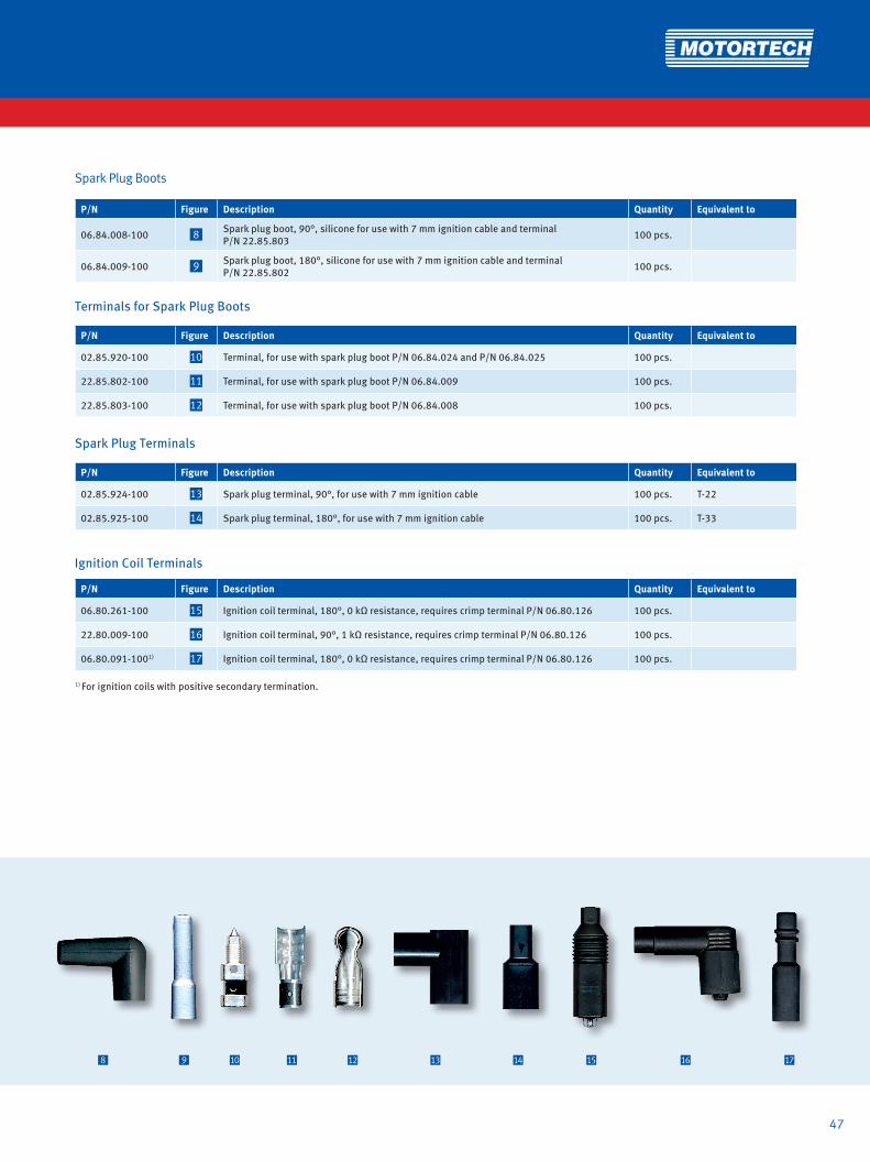
06.84.008-100 8 Spark plug boot, 90°, silicone for use with 7 mm ignition cable and terminal P/N 22.85.803 100 pcs.
06.84.009-100 9 Spark plug boot, 180°, silicone for use with 7 mm ignition cable and terminal P/N 22.85.802 100 pcs.
Spark Plug Boots
Terminals for Spark Plug Boots
P/N Figure Description Quantity Equivalent to
02.85.920-100 10 Terminal, for use with spark plug boot P/N 06.84.024 and P/N 06.84.025 100 pcs.
22.85.802-100 11 Terminal, for use with spark plug boot P/N 06.84.009 100 pcs.
22.85.803-100 12 Terminal, for use with spark plug boot P/N 06.84.008 100 pcs.
Spark Plug Terminals
P/N Figure Description Quantity Equivalent to
02.85.924-100 13 Spark plug terminal, 90°, for use with 7 mm ignition cable 100 pcs. T-22
02.85.925-100 14 Spark plug terminal, 180°, for use with 7 mm ignition cable 100 pcs. T-33
Ignition Coil Terminals
P/N Figure Description Quantity Equivalent to
06.80.261-100 15 Ignition coil terminal, 180°, 0 kΩ resistance, requires crimp terminal P/N 06.80.126 100 pcs.
22.80.009-100 16 Ignition coil terminal, 90°, 1 kΩ resistance, requires crimp terminal P/N 06.80.126 100 pcs.
06.80.091-1001) 17 Ignition coil terminal, 180°, 0 kΩ resistance, requires crimp terminal P/N 06.80.126 100 pcs.
1) For ignition coils with positive secondary termination.

48
HIGH TENSION LEADS AND EXTENSIONS
1 2 3 4 65
Crimp Terminals
P/N Figure Description Quantity Equivalent to
06.80.012-100 1 Crimp terminal, 180°, for use with spreading adaptor P/N 02.85.1012 100 pcs.
06.80.116-100 2 Crimp terminal, 90°, for use with MOTORTECH style ignition coils 100 pcs.
06.80.116-180-100 3 Crimp terminal, 180°, for use with New MOTORTECH style ignition coils 100 pcs.
06.80.108-100 4 Crimp terminal base, for use with crimp terminals P/N 06.80.116-100 and P/N 06.80.116-180-100 100 pcs.
06.80.126-100 5 Crimp terminal base, for use ignition coil terminals P/N 06.80.261 and P/N 22.80.009 100 pcs.
Accessories – Spreading Adaptor
P/N Figure Supersedes Description Quantity Equivalent to
02.85.1012-100 6 02.85.1004-100 Spreading adaptor for ALTRONIC® style ignition coils 100 pcs.
49
7 8 9 10 11 12 13 14 15
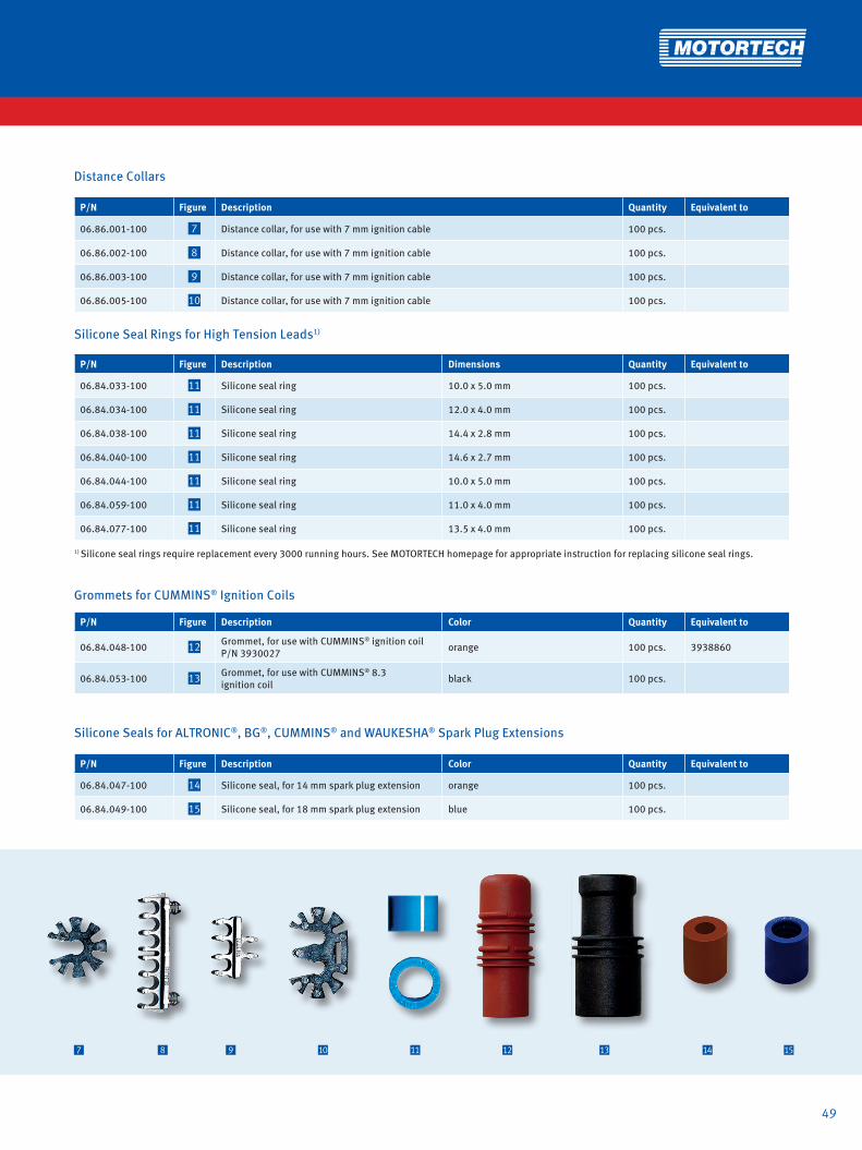
Distance Collars
P/N Figure Description Quantity Equivalent to
06.86.001-100 7 Distance collar, for use with 7 mm ignition cable 100 pcs.
06.86.002-100 8 Distance collar, for use with 7 mm ignition cable 100 pcs.
06.86.003-100 9 Distance collar, for use with 7 mm ignition cable 100 pcs.
06.86.005-100 10 Distance collar, for use with 7 mm ignition cable 100 pcs.
Silicone Seal Rings for High Tension Leads1)
P/N Figure Description Dimensions Quantity Equivalent to
06.84.033-100 11 Silicone seal ring 10.0 x 5.0 mm 100 pcs.
06.84.034-100 11 Silicone seal ring 12.0 x 4.0 mm 100 pcs.
06.84.038-100 11 Silicone seal ring 14.4 x 2.8 mm 100 pcs.
06.84.040-100 11 Silicone seal ring 14.6 x 2.7 mm 100 pcs.
06.84.044-100 11 Silicone seal ring 10.0 x 5.0 mm 100 pcs.
06.84.059-100 11 Silicone seal ring 11.0 x 4.0 mm 100 pcs.
06.84.077-100 11 Silicone seal ring 13.5 x 4.0 mm 100 pcs.
1) Silicone seal rings require replacement every 3000 running hours. See MOTORTECH homepage for appropriate instruction for replacing silicone seal rings.
Grommets for CUMMINS® Ignition Coils
P/N Figure Description Color Quantity Equivalent to
06.84.048-100 12 Grommet, for use with CUMMINS® ignition coil P/N 3930027 orange 100 pcs. 3938860
06.84.053-100 13 Grommet, for use with CUMMINS® 8.3 ignition coil black 100 pcs.
Silicone Seals for ALTRONIC®, BG®, CUMMINS® and WAUKESHA® Spark Plug Extensions
P/N Figure Description Color Quantity Equivalent to
06.84.047-100 14 Silicone seal, for 14 mm spark plug extension orange 100 pcs.
06.84.049-100 15 Silicone seal, for 18 mm spark plug extension blue 100 pcs.

50
HIGH TENSION LEADS AND ACCESSORIESHIGH TENSION LEADS AND EXTENSIONS
Spark Plug Extensions − PolyMot™ StyleBesides all the successful spark plug leads, MOTORTECH has also designed a large number of spark plug extensions under the PolyMot™ patented design. These extensions are unique and offer several advantages when being compared to the OEM or aftermarket competition. With the knowledge gathered in Ignition control and coil ma-nufacturing, a lot of the details were implemented into these products.
• Built in 5 kΩ resistor for RFI supression• Internal silicone seal for spark plug insulator• Top thread for easy removal with special tool• Long life product
MOTORTECH SPARK PLUG LEADS & EXTENSIONSPolyMot™
Comparison between OEM and MOTORTECH Spark Plug Extension for CATERPILLAR® G3520C and G3600 Series Gas Engines
1 Extra silicone seal ring for better insulation of ignition coil and spark plug extension
2 Spark plug extensions made of HyperFlonTM for high dielectric strength
3 Innovative spring-loaded secondary terminal inside ensures proper and reliable connection to spark plug (patented design)
4 MOTORTECH silicone seal ring for better insulation of spark plug insulator
1 2 3 4
MOTORTECH Spark Plug Extension P/N 06.80.459H
CATERPILLAR® Spark Plug Extension P/N 308-1380

PolyMot Spark Plug Extensions
P/N Supersedes Engine Make Model Extension Length Resistance Spark Plug P/N Silicone
Seal RingThread on Top End Equivalent to
06.80.320-T 06.80.320/H/H-T/ 06.80.381H/H-T CATERPILLAR® G3500 series 11 in. 5 kΩ GI3-3/
FB77WPCC 06.84.040 x 123-4710
06.80.319-T 06.80.319/H/H-T CATERPILLAR® G3600 series 11 in. 5 kΩ GI3-3/ FB77WPCC 06.84.040 x 123-8641
06.80.202-T 06.80.202 COOPER® 2400G series 9 in. 5 kΩ GI3-3/ FB77WPCC 06.84.040 656-701-003
06.80.755-T1) CUMMINS® QSK60G 13 in. 5 kΩ GI3-3/ FB77WPCC 06.84.040 x
06.80.756-T1) CUMMINS® QSV81/91G 15 in. 5 kΩ GI3-3/ FB77WPCC 06.84.040 x
06.80.460 WÄRSTSILÄ® 34SG series 18 in. 5 kΩ GI3-3/ FB77WPCC 06.84.040 0012E002200
06.80.461 WÄRSTSILÄ® 34SG series 17 in. 5 kΩ GI3-3/ FB77WPCC 06.84.040 0012E006500
06.80.469-T WAUKESHA® APG series 10 in. 5 kΩ GI3-3/ FB77WPCC 06.84.040 x A211797M
06.80.206-T 06.80.206 WAUKESHA® AT25 series 15 in. 5 kΩ GT3-1/RM77N 06.84.040 x A211357Y
06.80.330-T 06.80.330 WAUKESHA® AT25GL series 15 in. 5 kΩ GI3-3/ FB77WPCC 06.84.040 x A211797Y
06.80.213-T 06.80.213 WAUKESHA® AT27GL series 15 in. 5 kΩ GT3-1/RM77N 06.84.040 x A296064G
06.80.310-T 06.80.310 WAUKESHA® AT27GL-LR series 14 in. 5 kΩ GI3-3/
FB77WPCC 06.84.040 x A296064H
06.80.309-T 06.80.309 WAUKESHA® VGF series 9 in. 5 kΩ GI3-3/ FB77WPCC 06.84.040 x A211797J/
A211797K
06.80.321-T 06.80.321/H/H-T WAUKESHA® VHP-GL series 13 in. 5 kΩ GI3-3/ FB77WPCC 06.84.040 x A211797H/
A211797P
06.80.340-T 06.80.340 WAUKESHA® VHP-4 series 13 in. 5 kΩ GI3-3/ FB77WPCC 06.84.040 x A211797G
1) Fits application only, if conversion kits P/N 75.30.143 or 75.30.144 previously were used.
Removal Tool for Spark Plug Extensions with Thread on Top End
51
P/N Description
44.99.912 Spark plug extension removal tool

HIGH TENSION LEADS AND EXTENSIONS
Repair Kits for MOTORTECH Ignition Coils - For CATERPILLAR® G3400 and G3500 Series Gas Engines
P/N Figure Supersedes Description Application Extension Length
Extension Diameter Fits Ignition Coil P/N
06.80.741 1 - Ignition coil repair kit G3400 - Non CSA 95 mm 30 mm 06.50.141/06.50.145
06.80.742 1 - Ignition coil repair kit G3400 - CSA 97 mm 30 mm 06.50.142/06.50.146
06.80.743 1 - Ignition coil repair kit G3400 - Non CSA 107 mm 30 mm 06.50.143/06.50.147
06.80.744 1 - Ignition coil repair kit G3400 - CSA 109 mm 30 mm 06.50.144/06.50.148
06.80.751 1 - Ignition coil repair kit G3500 - Non CSA 118 mm 30 mm 06.50.151/06.50.155
06.80.752 1 - Ignition coil repair kit G3500 - CSA 105 mm 30 mm 06.50.152/06.50.156
06.80.753 1 - Ignition coil repair kit G3500 - Non CSA 112 mm 30 mm 06.50.153/06.50.157
06.80.754 1 - Ignition coil repair kit G3500 - CSA 105 mm 30 mm 06.50.154/06.50.158
Above Repair Kits contain following Sub Components
P/N P/N Extension including Seal
P/N included Spark Plug Seal
P/N included Extension Seal P/N Lip Seal P/N Secondary
Terminal
06.80.741 06.80.741-2 06.84.059 06.81.051 02.85.881
06.80.742 06.80.742-2 06.84.059 06.81.084 06.81.051 06.51.134
06.80.743 06.80.743-2 06.84.059 06.81.051 06.51.136
06.80.744 06.80.744-2 06.84.059 06.81.084 06.81.051 06.51.133
06.80.751 06.80.751-2 06.84.040 06.81.051 02.85.881
06.80.752 06.80.752-2 06.84.040 06.81.084 06.81.051 02.85.870
06.80.753 06.80.753-2 06.84.040 06.81.051 02.85.881
06.80.754 06.80.754-2 06.84.040 06.81.084 06.81.051 02.85.870
1 2 3
52
4

53
Teflon Extensions for CATERPILLAR® Ignition Coils
P/N Figure Description Extension Length Extension Diameter Equivalent to
06.80.356H 2 Teflon extension 118 mm 25 mm 133-5078
06.80.360H 2 Teflon extension 118 mm 30 mm 169-4295
Spark Plug Extension for MOTORTECH/CATERPILLAR® Ignition Coil – For CATERPILLAR® G3520C and G3600 Series Gas Engines
P/N Figure Description Application Resistance Extension Length Extension Diameter
Fits Ignition Coil P/N Equivalent to
06.80.459H1) 3 Spark Plug Extension G3520C/G3600 Non CSA 0 kΩ 248 mm 26 mm
06.50.161/ 06.50.162/ 283-5270
283-5271, 308-1380
06.80.600 4 Spark Plug Extension G3520C/G3600 Non CSA 0 kΩ 252 mm 26 mm 06.50.164/
06.50.166
1) Supersedes spark plug extensions P/N 06.80.375H and 06.80.446H.
P/N P/N Extension including Seal
P/N included Spark Plug Seal
P/N included Extension Seal P/N Lip Seal P/N Secondary Terminal
06.80.419H 06.80.279H 06.84.059 06.81.051 02.85.881
06.80.742 06.80.742-2 06.84.059 06.81.084 06.81.051 06.51.134
06.80.420H 06.80.280H 06.84.059 06.81.051 06.51.136
06.80.744 06.80.744-2 06.84.059 06.81.084 06.81.051 06.51.133
06.80.515H 06.80.335H-1 06.84.040 06.81.051 02.85.881
06.80.752 06.80.752-2 06.84.040 06.81.084 06.81.051 02.85.870
06.80.480 06.80.481 06.84.040 06.81.051 02.85.881
06.80.754 06.80.754-2 06.84.040 06.81.084 06.81.051 02.85.870
Above Repair Kits contain following Sub Components
Extension Rods – Low Cost Style1)
P/N2) Description Primary Connection Secondary Connection Equivalent to
06.80.349-L Extension rod SAE snap-on attachment TCRC-"L"
06.80.376-L Extension rod SAE #8-32 screw-on attachment TCR-"L"
06.80.376-10 Extension rod SAE #8-32 screw-on attachment TCR-10WM / 207927A1) We recommend using PolyMot high tension leads. 2) Standard lengths ("-L") = 3 in., 4 in., 5 in., 6 in., 8 in., 10 in., 12 in., 14 in., 16 in., 18 in., 20 in., 24 in.; other lengths available on request.
P/N Figure Supersedes Description Application Extension Length
Extension Diameter Fits Ignition Coil P/N
06.80.419H 1 Ignition coil repair kit G3400 - Non CSA 95 mm 30 mm 232-6348, 165-1591, 131-3277, 129-8802, 108-0615
06.80.742 1 06.80.418H Ignition coil repair kit G3400 - CSA 97 mm 30 mm 232-6349, 165-1592, 122-8070
06.80.420H 1 Ignition coil repair kit G3400 - Non CSA 107 mm 30 mm 232-6352, 213-7443
06.80.744 1 06.80.417H Ignition coil repair kit G3400 - CSA 109 mm 30 mm 232-6353, 213-7444
06.80.515H 1 06.80.315H Ignition coil repair kit G3500 - Non CSA 118 mm 30 mm 232-6346, 165-1589, 124-0749
06.80.752 1 06.80.415H Ignition coil repair kit G3500 - CSA 105 mm 30 mm 232-6347, 165-1590
06.80.480 1 Ignition coil repair kit G3500 - Non CSA 112 mm 30 mm 232-6350
06.80.754 1 06.80.415H Ignition coil repair kit G3500 - CSA 105 mm 30 mm 259-2078
Repair Kits for CATERPILLAR® Ignition Coils - For CATERPILLAR® G3400 and G3500 Series Gas Engines

54
HIGH TENSION LEADS AND EXTENSIONS
There is an alternative to the commonly failing conventional shielded high tension lead. MOTORTECH has designed a CSA approved shielded spark plug lead for Class I, Division2, Group D that will perform better than the industry standard. There is no need to convert to non-shielded when you can not keep the engine running with the conventional leads.
SHIELDED HIGH TENSION LEADMOT-Blues
The MOT-Blues spark plug wire is specially designed for shielded CSA certified high tension leads. It consists of a multi layer design:• Nickel plated copper core• 2 layers of silicone• Stainless steel braid• Silicone jacket
This design ensures that no humidity can be trapped in the lead.

55
1) Standard braid lengths = „L“ = 10 in., 13 in., 16 in., 18 in., 20 in., 21 in., 22 in., 24 in., 30 in., 35 in.; other lengths available on request. 2) Consult factory for 1 in. spark plug terminal well depth.All terminals made of ceramic. HEX-nut on both sides.
-L
P/N1) Description Spark Plug Terminal Well Depth2)
Spark Plug Termination
Ignition Coil Termination Equivalent to
95.91.030-L Shielded high tension lead 2 in. 3/4-20 UNEF / 180° 1-20 UNEF / 180° A755-L-2 / HT2400-L
MOT-Blues Shielded High Tension Leads for Externally Mounted Ignition Coils – MOTORTECH Style
MOT-Blues Shielded High Tension Leads for Externally Mounted Ignition Coils – ALTRONIC® Style
P/N1) Description Spark Plug Terminal Well Depth2)
Spark Plug Termination
Ignition Coil Termination Equivalent to
95.90.030-L Shielded high tension lead 2 in. 3/4-20 UNEF / 180° 3/4-20 UNEF / 180° 593030-L / HT2300-L
1) Standard lead lengths = „L“ = 10 in., 13 in., 16 in., 18 in., 20 in., 21 in., 22 in., 24 in., 30 in., 35 in.; other lengths available on request.2) Consult factory for 1 in. spark plug terminal well depth.All terminals made of ceramic. HEX-nut on spark plug side.
P/N1) Description Spark Plug Terminal Well Depth2)
Spark Plug Termination
Ignition Coil Termination Equivalent to
95.85.030-L Shielded high tension lead 2 in. 3/4-20 UNEF / 180° 1-20 UNEF / 180° A755-L-2 / HT2400-L
Conventional Shielded High Tension Leads for Externally Mounted Ignition Coils – MOTORTECH Style
Conventional Shielded High Tension Leads for Externally Mounted Ignition Coils – ALTRONIC® Style
P/N1) Description Spark Plug Terminal Well Depth2)
Spark Plug Termination
Ignition Coil Termination Equivalent to
95.80.030-L Shielded high tension lead 2 in. 3/4-20 UNEF / 180° 3/4-20 UNEF / 180° 593030-L / HT2300-L
-L

56
HIGH TENSION LEADS AND EXTENSIONS
P/N Description Stud Thread Size Adaptor Equivalent to
02.85.1006 Terminal kit - Spark plug M3 3/4-20 UNEF, 2 in. terminal well depth1)
02.85.1007 Terminal kit - Ignition coil M3 3/4-20 UNEF, ALTRONIC® Style
02.85.1008 Terminal kit - Ignition coil M3 1-20 UNEF, MOTORTECH Style
Terminal Kits for Shielded High Tension Leads – MOT-Blues
1) Consult factory for terminal kits to fit spark plugs with 3/4-20 UNEF thread and 1 in. terminal well depth.
Terminal Kits for Shielded High Tension Leads – Conventional
P/N Description Stud Thread Size Adaptor Equivalent to
02.85.991 Terminal kit - Spark plug M3 3/4-20 UNEF, 1 in. terminal well depth
02.85.991-2 Terminal kit - Spark plug 3/48 UNC 3/4-20 UNEF, 1 in. terminal well depth SC1K / 504205
02.85.992 Terminal kit - Spark plug M3 3/4-20 UNEF, 2 in. terminal well depth
02.85.992-2 Terminal kit - Spark plug 3/48 UNC 3/4-20 UNEF, 2 in. terminal well depth SC2K / 504137
02.85.979 Terminal kit - Spark plug 3/48 UNC 3/4-20 UNEF, 1 in. terminal well depth
02.85.992-1 Terminal kit - Ignition coil M3 3/4-20 UNEF, BENDIX® Style
02.85.992-3 Terminal kit - Ignition coil 3/48 UNC 3/4-20 UNEF, BENDIX® Style
02.85.996 Terminal kit - Ignition coil M3 3/4-20 UNEF, ALTRONIC® Style
02.85.996-2 Terminal kit - Ignition coil 3/48 UNC 3/4-20 UNEF, ALTRONIC® Style ALTSS-2
02.85.997 Terminal kit - Ignition coil M3 1-20 UNEF, MOTORTECH Style
02.85.997-2 Terminal kit - Ignition coil 3/48 UNC 1-20 UNEF, MOTORTECH Style
Terminal Kits for Non-Shielded High Tension Leads – Conventional
P/N Description Stud Thread Size Adaptor Equivalent to
02.85.993 Terminal kit - Ignition coil M3 3/4-20 UNEF, ALTRONIC® Style
02.85.993-2 Terminal kit - Ignition coil 3/48 UNC 3/4-20 UNEF, ALTRONIC® Style ALTOS-1 / 510480
02.85.994 Terminal kit - Ignition coil M3 3/4-20 UNEF, BENDIX® Style
02.85.994-2 Terminal kit - Ignition coil 3/48 UNC 3/4-20 UNEF, BENDIX® Style BENDOS-1
02.85.995 Terminal kit - Ignition coil M3 1-20 UNEF, MOTORTECH Style
02.85.995-2 Terminal kit - Ignition coil 3/48 UNC 1-20 UNEF, MOTORTECH Style FMOS-1

57
P/N1) Figure Description Spark Plug Connection
Terminal Well Depth
Ignition Coil Connection
Terminal Well Depth Equivalent to
95.07.010-L 1 Integral ignition coil adaptor 5/8-24 UNEF 1 in. 1-20 UNEF 2 in. BG E Series
95.07.011-L 1 Integral ignition coil adaptor 3/4-20 UNEF 1 in. 1-20 UNEF 2 in. 593120-L / M“L“-2C
95.07.012-L 1 Integral ignition coil adaptor 3/4-20 UNEF 2 in. 1-20 UNEF 2 in. 593130-L / M“L“1C
95.07.013-L 1 Integral ignition coil adaptor 13/16-20 UNEF 2 in. 1-20 UNEF 2 in. 593140-L
Integral Ignition Coil Adaptors for Shielded Spark Plugs
1) Standard lengths („-L“) = 1.5 in., 3 in., 6 in., 9 in., 11 in., 19 in.; other lengths available on request.
P/N1) Figure Description Spark Plug Connection
Terminal Well Depth
High Tension Lead Connection
Terminal Well Depth Equivalent to
95.07.020-L 2 Shielded spark plug extension 5/8-24 UNEF 1 in. 5/8-24 UNEF 1 in.
95.07.021-L 2 Shielded spark plug extension 3/4-20 UNEF 1 in. 3/4-20 UNEF 1 in. M“L“-2S
95.07.022-L 2 Shielded spark plug extension 3/4-20 UNEF 2 in. 3/4-20 UNEF 2 in. M“L“-2E
95.07.023-L 2 Shielded spark plug extension 5/8-24 UNEF 1 in. 3/4-20 UNEF 2 in.
95.07.024-L 2 Shielded spark plug extension 3/4-20 UNEF 1 in. 3/4-20 UNEF 2 in.
Extensions for Shielded Spark Plugs
1) Standard lengths („-L“) = 4 in., 5 in., 6 in., 8 in., 10 in., 12 in., 18 in.; other lengths available on request.
1 2
SHIELDED

58
New Flex Style Shielded Primary Leads
In addition to its conventional primary leads, MOTORTECH now offers a new type of primary lead that is produced with a special wire. The new primary leads are compliant with CSA Class I, Division 2, Group D, and they offer a significantly higher flexibility than conventional leads, shielded with braided steel, while being highly resistant to all kinds of environmental conditions.The multi-layer design of the wire is free of entrapped air and prevents the accumu-lation of condensed water which can result in primary voltage flash-overs. Several different configurations with durable 90-degrees and 180-degrees 2-pole and 3-pole connectors are available.
PRIMARY LEADS
·Fine bare copper wire·PVC/Nylon insulation· Aluminum-plated foil and tinned copper braid·PVC jacket·Temperature range -40° C to +90° C (-40° F to +194° F) This design ensures that no humidity can be trapped in the lead.
The new oil and UV resistant multi-conductor wire is specially designed for shielded CSA certified primary leads. It consists of a multi layer design:

59
-L Coil ConnectorOutlet Box Adaptor
Shielded Non-Shielded
Ignition Coil Connector Outlet Box Adaptor Conductor Equivalent toNew Flex Style Conventional Style
P/N1)
95.01.110-L 95.01.010-L MIL Style 3 pole socket, 180° 1/2-14 NPT, 180° 2 wire 593022-L
95.01.110-L-3 95.01.010-L-3 MIL Style 3 pole socket, 180° 3/8-18 NPT, 180° 2 wire LT73002-L
95.01.120-L 95.01.020-L MIL Style 3 pole socket, 90° 1/2-14 NPT, 180° 2 wire 593027-L
95.01.120-L-3 95.01.020-L-3 MIL Style 3 pole socket, 90° 3/8-18 NPT, 180° 2 wire LT73012-L
95.01.121-L 95.01.021-L MIL Style 3 pole socket, 90° 1/2-14 NPT, 180° 2 wire 593029-L
95.01.122-L 95.01.022-L MIL Style 3 pole socket, 90° 1/2-14 NPT, 180° 2 wire2) 593036-L
95.01.123-L 95.01.023-L MIL Style 3 pole socket, 180° 1/2-14 NPT, 180° 2 wire2) 593035-L
Primary Leads – 3 Pole Ignition Coil Connection
1) Standard braid lengths („-L“) = 6 in., 9 in., 12 in., 15 in., 18 in., 24 in., 30 in., 36 in., 42 in., 48 in., 54 in., 60 in., 72 in., 84 in., 96 in., 108 in., 120 in., 135 in., 138 in., 150 in.; other lengths available on request.2) Wire length is double of braid length.
Repair Kits for Conventional Style Shielded Primary Leads – 3 Pole Ignition Coil Connection
P/N Description Lead length Ignition Coil Connector Conductor
For use with Primary Lead, Length 10 – 180 in.
Equivalent to
95.01.010-42-RC Repair kit 42 in. MIL Style 3 pole socket, 180° 2 wire 95.01.010-L, 593022-L 583017-42
95.01.010-60-RC Repair kit 60 in. MIL Style 3 pole socket, 180° 2 wire 95.01.010-L, 593022-L 583017-60
95.01.010-96-RC Repair kit 96 in. MIL Style 3 pole socket, 180° 2 wire 95.01.010-L, 593022-L 583017-96
95.01.010-180-RC Repair kit 180 in. MIL Style 3 pole socket, 180° 2 wire 95.01.010-L, 593022-L 583017-180
95.01.020-42-RC Repair kit 42 in. MIL Style 3 pole socket, 90° 2 wire 95.01.020-L, 593027-L 583018-42
95.01.020-60-RC Repair kit 60 in. MIL Style 3 pole socket, 90° 2 wire 95.01.020-L, 593027-L 583018-60
95.01.020-96-RC Repair kit 96 in. MIL Style 3 pole socket, 90° 2 wire 95.01.020-L, 593027-L 583018-96
95.01.020-180-RC Repair kit 180 in. MIL Style 3 pole socket, 90° 2 wire 95.01.020-L, 593027-L 583018-180
New Flex Style
Conventional Style

60
PRIMARY LEADS
Conversion: 1 inch = 25,4 mm / 1 foot = 0,3 m
-L Coil ConnectorOutlet Box Adaptor
Primary Leads – 2 Pole Ignition Coil Connection
Shielded Non-Shielded
Ignition Coil Connector Outlet Box Adaptor Conductor Equivalent toNew Flex Style Conventional Style
P/N1)
95.06.110-L 95.06.010-L MIL Style 2 pole socket, 180° 1/2-14 NPT, 180° 2 wire A754-L / LT2001-L
95.06.120-L 95.06.020-L MIL Style 2 pole socket, 90° 1/2-14 NPT, 180° 2 wire B754-L / LT2011-L
95.06.030-L MIL Style 2 pole socket, 180° 5/8-24 NPT, 90° 2 wire C754-L / LT2100-L
1) Standard braid lengths („-L“) = 6 in., 9 in., 12 in., 15 in., 18 in., 24 in., 30 in., 36 in., 42 in., 48 in., 54 in., 60 in., 72 in., 84 in., 96 in., 108 in., 120 in., 135 in., 138 in., 150 in.; other lengths available on request.
Shielded Non-Shielded
Ignition Coil Connector Electronic Box Connector Conductor Equivalent toNew Flex Style Conventional Style
P/N1)
95.01.130-L 95.01.030-L MIL Style 3 pole socket, 90° MIL Style 3 pole socket, 180° 2 wire 593069-L
95.01.131-L 95.01.031-L MIL Style 3 pole socket, 90° MIL Style 3 pole pin, 90° 2 wire
95.01.133-L 95.01.033-L MIL Style 3 pole socket, 90° MIL Style 3 pole socket, 180° 3 wire
Primary Leads – 3 Pole Ignition Coil Connection – Special
1) Standard braid lengths („-L“) = 6 in., 9 in., 12 in., 15 in., 18 in., 24 in., 30 in., 36 in., 42 in., 48 in., 54 in., 60 in., 72 in., 84 in., 96 in., 108 in., 120 in., 135 in., 138 in., 150 in.; other lengths available on request.
Shielded Non-Shielded
Ignition Coil Connector Electronic Box Connector Conductor Equivalent toNew Flex Style Conventional Style
P/N1)
95.01.132-L 95.01.032-L MIL Style 2 pole pin, 90° MIL Style 2 pole pin, 90° 2 wire
Primary Lead – 2 Pole Ignition Coil Connection – Special
1) Standard braid lengths („-L“) = 6 in., 9 in., 12 in., 15 in., 18 in., 24 in., 30 in., 36 in., 42 in., 48 in., 54 in., 60 in., 72 in., 84 in., 96 in., 108 in., 120 in., 135 in., 138 in., 150 in.; other lengths available on request.
Cable Assemblies
Shielded Non-Shielded
Ignition Coil Connector Outlet Box Adaptor Conductor Equivalent toNew Flex Style Conventional Style
P/N1)
95.01.111-L 95.01.011-L MIL Style 3 pole socket, 180° 1/2-14 NPT, 180° 3 wire
95.01.124-L 95.01.024-L MIL Style 3 pole socket, 90° 1/2-14 NPT, 180° 3 wire 593024-L
95.01.025-L MIL Style 4 pole socket, 90° 1/2-14 NPT, 180° 5 wire 593025-L
95.01.026-L MIL Style 5 pole socket, 90° 1/2-14 NPT, 180° 6 wire 593026-L
1) Standard braid lengths („-L“) = 6 in., 9 in., 12 in., 15 in., 18 in., 24 in., 30 in., 36 in., 42 in., 48 in., 54 in., 60 in., 72 in., 84 in., 96 in., 108 in., 120 in., 135 in., 138 in., 150 in.; other lengths available on request.
New Flex Style
Conventional Style

61
Primary Leads for CUMMINS® QSK60G and QSV81/91G Gas Engines1)
Shielded Non-Shielded
Ignition Coil Connector Wiring Rail Connector Conductor Equivalent toNew Flex Style Conventional Style
P/N2)
06.30.142-14 MIL Style 3 pole socket, 90° 3 pole socket, 180° 2 Wire
1) Fits application only, if conversion kits P/N 75.30.143 or 75.30.144 previously were used.2) Standard lead length 14 in.; other lengths available on request.
Shielded Non-Shielded
Ignition Coil Connector Wiring Rail Connector Conductor Equivalent toNew Flex Style Conventional Style
P/N1)
95.01.012-11 MIL Style 3 pole socket, 90° 3 pole socket, 90° 2 wire 702930 / 593068-1
95.01.013-30 MIL Style 3 pole socket, 90° 3 pole socket, 180° 2 wire 705165 / 593068-2
Primary Leads for Rolls-Royce® Gas Engines
Primary Leads for WAUKESHA® Gas Engines
Shielded Non-Shielded
Ignition Coil Connector Wiring Rail Connector Conductor Equivalent toNew Flex Style Conventional Style
P/N
95.01.107-241) A740746-MOT MIL Style 3 pole socket, 90° 3 pole socket, 180° 2 Wire A740746
740746B-MOT 2 Wire, 180° 3 pole socket, 180° 2 Wire 740746B
1) Standard braid lengths 11 in. and 30 in.; other lengths available on request.
1) Standard lead length 24 in.; other lengths available on request.
Shielded Non-Shielded
Ignition Coil Connector Wiring Rail Connector Conductor Equivalent toNew Flex Style Conventional Style
P/N1)
95.01.140-L 95.01.040-L 06.01.040-L MIL Style 3 pole socket, 180° MIL Style 2 pole pin, 180° 2 wire
95.01.141-L 95.01.041-L 06.01.041-L MIL Style 3 pole socket, 90° MIL Style 2 pole pin, 180° 2 wire
95.01.142-L 95.01.042-L 06.01.042-L MIL Style 2 pole socket, 180° MIL Style 2 pole pin, 180° 2 wire
95.01.143-L 95.01.043-L 06.01.043-L MIL Style 2 pole socket, 90° MIL Style 2 pole pin, 180° 2 wire
95.01.144-L 95.01.044-L 06.01.044-L MIL Style 3 pole socket, 180° MIL Style 2 pole pin, 90° 2 wire
95.01.145-L 95.01.045-L 06.01.045-L MIL Style 3 pole socket, 90° MIL Style 2 pole pin, 90° 2 wire
95.01.146-L 95.01.046-L 06.01.046-L MIL Style 2 pole socket, 180° MIL Style 2 pole pin, 90° 2 wire
95.01.147-L 95.01.047-L 06.01.047-L MIL Style 2 pole socket, 90° MIL Style 2 pole pin, 90° 2 wire
Primary Leads for MOTORTECH AlphaRail Wiring Rails
1) Standard lead lengths („-L“) = 6 in., 9 in., 12 in., 15 in., 18 in., 24 in., 30 in., 36 in., 42 in., 48 in., 54 in., 60 in., 72 in., 84 in.; other lengths available on request. Add suffix „-X“ to part number for cross wired primary leads for positive grounded ignition systems.

62
WIRING RAIL SYSTEMS
MOTORTECH stainless steel, vibration resistant rail assembly will withstand any harsh environment commonly found in the oil & gas industry. Our proven design is made for engine manufactur-ers and the global aftermarket. Do not go Low-Tech and take the risk of engine down time because of equipment being under repair. Eliminate the need for constant rewiring, connector exchanges or straightening out weak and bent aluminum wiring rails.
• Made of stainless steel
• Rigid military style connectors
• Rails are filled with special foam to ensure that all wires are separated from ground and will not vibrate
• Water proof design – built to last in uncovered environment
• Repairable by MOTORETCH‘s assigned distributors in the event of mechanically damage
• Ignition rails can be used for shielded and non-shielded applications.
• Due to easy base rail structure easy for stocking
• Quick service access with disconnetable connections
MOTORTECH IGNITION RAIL SYSTEMAlphaRail

63
Specification Charts:
www.motortech.de
2
Configuration Help – In-line Engine
In-Line Engine – One Rail
In-Line Engine – One Double Rail
In-Line Engine – Two Rails
JunctionBox
JunctionBox
JunctionBox
3
V-Engine – Two Rails
V-Engine – Two Double Rails
V-Engine – Four Rails
Configuration Help – V-Engine
JunctionBox
JunctionBox
JunctionBox
JunctionBox
4
Specification Table
B = Number of Cylinders per BankConfiguration 1
CD = Distance between the Cylinders
a = Ignition Coils per Cylinder
F = Double Rail-Length of Connecting Flex Conduit
HJ = Distance between two Ignition Coils – Only for two Ignition Coils per Cylinder
Specify Wiring Rail A Specify Wiring Rail B
One Ignition Coil Two Ignition Coils
5
a = Ignition Coils per Cylinder6 = Engine with one ignition coil per cylinder7 = Engine with two ignition coils per cylinder 1)
NOTE: 1) See HJ for distance between two ignition coils.
B = Number of Cylinders per Bank1 = Special version2 = 2 cylinders3 = 3 cylinders4 = 4 cylinders5 = 5 cylinders
CD = Distance between the Cylinders04 = 4“06 = 6“07 = 7“08 = 8“10 = 10“11 = 11“Other length: NOTE: Other code digits given by factory.
E = Ignition Coil MountingN = STANDARD – NO ignition coil mounted
F = Double Rail-Length of Connecting Flex ConduitA = NO Double RailB = 12“C = 16“D = 20“E = 24“F = 32“
g = Specification of Ignition CoilN = STANDARD – NO ignition coil mounted NOTE: Ignition coils have to be ordered separately (see page 8-10)
HJ = Distance between two Ignition Coils – Only for two Ignition Coils per Cylinder04 = 4“06 = 6“08 = 8“10 = 10“12 = 12“14 = 14“
12 = 12“13 = 13“14 = 14“16 = 16“27 = 27“33 = 33“
6 = 6 cylinders8 = 8 cylinders0 = 10 cylinders
G = 40“H = 52“
16 = 16“18 = 18“20 = 20“22 = 22“24 = 24“
P/N 95.8A.BCD-EFG-HJP/N 95.8 . -N N-
Conversion: 1“ (Inch) = 25.4 mm / 1 ft. (foot) = 0.3 m
NOTE: If the distance between the first and last cylinder exceeds 114“ or more than 12 ignition coils per bank are needed, two separate ignition rails have to be specified. For example see Configuration I.
NOTE: Two ignition wiring rails connected by flex conduit (12 Ignition Coils in total max.)
6
Installation Instructions
Simultaneous installation of two different wiring railsIf, along with the wiring for the ignition you also carry out wiring of a detonation control via an AlphaRail, for example, both rails can be connected together as you can see on the left side.
Mounting Wiring RailPlease adhere to the following criteria, before selecting suita-ble brackets for fastening of the wiring rail on the engine:
• The distance between two fastening points must be a maxi-mum of 1 m (3.28“).
• The heat radiation must not be too high (max. 80 °C/176 °F).
• The selected fastening points on the engine must carry the weight of the wiring rail. Also take into account any vibra-tions that may occur.
• The wiring rails must be attached so that the ignition coils can be installed at the height of the respective cylinder and the primary and secondary wiring can be performed with no problem and secure (e. g. without kinks).
• When selecting the fastening location also pay attention to the ease of installation and maintenance.
Brackets will be installed, as shown in the illustration, on the wiring rails with the spacing of the chosen fastening points.
Note: Instead of the straight fastening bracket (see illustra-tion) an angled bracket can also be used. Options of 150° or 90° are available.
7
Bracket Configuration
P/n Desciption
75.10.303 bracket, 40 x 40 mm (standard)
75.10.097 flat bar, 180° (standard)
75.10.120 flat bar, 150°
75.10.280 flat bar, 90°
NOTE: Please order separately!
alternative
alternative
8
Installation Instructions
If integral coils are used, the assembly of the ignition coils on the rail and the connection to the high tension lead are not re-quired. This type of coil is installed directly on the spark plug.
Non shielded ignition coil Shielded ignition coil
Mounting Primary Wiring
Mounting Ignition Coils
Non shielded ignition coil Shielded ignition coil
11
Ignition Coils
Ignition Coils – shielded – Integral – 2 Pin Primary Connector Arrangement
Outer Thread Inner Thread
P/n Equivalent to Polarity Primary Terminal length 1“-20 13/16“-20 aSC Compatible Ignition Controllers
95.08.030-6 PPT2477AA6 (-) ground 2 pol. military style 5.78“ x MIC500/MIC850
95.08.030-8 PPT2477AA8 (-) ground 2 pol. military style 8.15“ x MIC500/MIC850
95.08.030-10 PPT2477AA10 (-) ground 2 pol. military style 10.15“ x MIC500/MIC850
95.08.030-12 PPT2477AA12 (-) ground 2 pol. military style 12.15“ x MIC500/MIC850
95.08.040-6 PPT2477AB6 (-) ground 2 pol. military style 5.50“ x x x MIC500/MIC850
95.08.040-17 PPT2477AB17 (-) ground 2 pol. military style 17.00“ x x x MIC500/MIC850
95.08.050-101) (-) ground 2 pol. military style 10.00“ x x MIC500/MIC850
95.08.050-11 (-) ground 2 pol. military style 11.00“ x x MIC500/MIC850
95.08.050-122) PPT2477AB12 (-) ground 2 pol. military style 12.00“ x x MIC500/MIC850
95.08.050-14.5 (-) ground 2 pol. military style 14.50" x x MIC500/MIC850
95.08.050-17 (-) ground 2 pol. military style 17.00" x x MIC500/MIC850
Ignition Coils – shielded – Integral – 3 Pin Primary Connector Arrangement
Outer Thread Inner Thread
P/n Equivalent to Polarity Primary Terminal length 1“-20 13/16“-20 aSC Compatible Ignition Controllers
95.09.030 591007 (-) ground 3 pol. military style 5.8“ x MIC500/ALT I/ALT III/ALT V/CD200/CD200D/DISN/CPU90/
95.09.0313) 591008 (+) ground 3 pol. military style 5.82“ x ALT II/CPU90
95.09.040-6 591011A (-) ground 3 pol. military style 5.78“ x MIC500/ALT I/ALT III/ALT V/CD200/CD200D/DISN/CPU90/CPU95
95.09.040-10 (-) ground 3 pol. military style 10.15“ x MIC500/ALT I/ALT III/ALT V/CD200/CD200D/DISN/CPU90/CPU95
95.09.040-12 591011B / 591011C (-) ground 3 pol. military style 12.15“ x MIC500/ALT I/ALT III/ALT V/CD200/
CD200D/DISN/CPU90/CPU95
95.09.050-6 (-) ground 3 pol. military style 5.50“ x x x MIC500/MIC850
95.09.060-101) (-) ground 3 pol. military style 10.00“ x x MIC500/MIC850
95.09.060-11 (-) ground 3 pol. military style 11.00“ x x MIC500/MIC850
95.09.060-122) (-) ground 3 pol. military style 12.00“ x x MIC500/MIC850
95.09.060-14.5 (-) ground 3 pol. military style 14.50“ x x MIC500/MIC850
95.09.060-17 (-) ground 3 pol. military style 17.00“ x x MIC500/MIC850
Conversion: 1“ (Inch) = 25.4 mm / 1 ft. (foot) = 0.3 m
NOTE: 1) for use on Waukesha VHP-GL with Rain ShieldNOTE: 2) for use on Waukesha VHP-GSI with Rain ShieldNOTE: 3) Polarity (+) groundNOTE: Ignition coils have to be ordered separately in required quantity.
NOTE: 1) for use on WAUKESHA VHP-GL with rain shieldNOTE: 2) for use on WAUKESHA VHP-GSI with rain shieldNOTE: Ignition coils have to be ordered separately in required quantity.
12
Primary leads
Primary Leads to connect Ignition wiring rail and Ignition Coil
P/n Ignition Coil Connector Connector Style Wiring Rail Connector Connector Style
95.01.040-L 180° 180°
95.01.041-L 90° 180°
95.01.042-L 180° 180°
95.01.043-L 90° 180°
95.01.044-L 180° 90°
95.01.045-L 90° 90°
95.01.046-L 180° 90°
95.01.047-L 90° 90°
13
Harness to connect Ignition Wiring Rail and Junction Box – 90° Connector Style
P/n Description length
95.40.314-15 harness, socket 15 ft.
95.40.314-25 harness, socket 25 ft.
95.40.314-50 harness, socket 50 ft.
Harness to connect Ignition Wiring Rail and Junction Box – 180° Connector Style
P/n Description length
95.40.114-15 harness, socket 15 ft.
95.40.114-25 harness, socket 25 ft.
95.40.114-50 harness, socket 50 ft.
Harnesses
Conversion: 1“ (Inch) = 25.4 mm / 1 ft. (foot) = 0.3 m
L-
L-

64
WIRING RAIL SYSTEMSWIRING RAIL SYSTEMS
Wiring Rail Kits for CATERPILLAR® G3300 and G3400 Series Gas Engines – Shielded Applications
P/N Description
95.75.025-1 Ignition wiring rail kit without ignition control unit for CATERPILLAR® G3304• Incl. harness to ALTRONIC® magneto• Mounting bracket welded to the rail• G-lead connector• 4 shielded primary leads to fit 3 pole integral ignition coils1)
• 1 Timing adaptor
95.75.024-1 Ignition wiring rail kit without ignition control unit for CATERPILLAR® G3306• Incl. harness to ALTRONIC® magneto• Mounting bracket welded to the rail• G-lead connector• 6 shielded primary leads to fit 3 pole integral ignition coils1)
• 1 Timing adaptor
95.75.067-1 Ignition wiring rail kit without ignition control unit for CATERPILLAR® G3406• Incl. harness to ALTRONIC® ignition control unit• Mounting bracket welded to the rail• G-lead connector• 6 shielded primary leads to fit 3 pole integral ignition coils1)
• 1 Timing adaptor
1) Integral ignition coils needs to be ordered separately.
P/N Supersedes Description
75.00.536 75.00.338 Ignition upgrade kit for CATERPILLAR® G3304• Incl. MIC3 ignition controller• Input and output harnesses• AlphaRail wiring rail with high energy ignition coils and brackets• High tension leads• Mechanical trigger kit with disc (4+1), adapter ring, gaskets and pickup• Magneto drive cover kit
75.00.537 75.00.337 Ignition upgrade kit for CATERPILLAR® G3306• Incl. MIC3 ignition controller• Input and output harnesses• AlphaRail wiring rail with high energy ignition coils and brackets• High tension leads• Mechanical trigger kit with disc (6+1), adapter ring, gaskets and pickup• Magneto drive cover kit
75.00.538 75.00.336 Ignition upgrade kit for CATERPILLAR® G3406• Incl. MIC3 ignition controller• Input and output harnesses• AlphaRail wiring rail with high energy ignition coils and brackets• High tension leads• Mechanical trigger kit with disc (6+1), adapter ring, gaskets and pickup• Magneto drive cover kit
75.00.539 Ignition upgrade kit for CATERPILLAR® G3408• Incl. MIC3 ignition controller• Input and output harnesses• AlphaRail wiring rails with high energy ignition coils and brackets• High tension leads• TriDev trigger device and pickup
75.00.540 Ignition upgrade kit for CATERPILLAR® G3412• Incl. MIC3 ignition controller• Input and output harnesses• AlphaRail wiring rails with high energy ignition coils and brackets• High tension leads• TriDev trigger device and pickup
Ignition Upgrade Kits for CATERPILLAR® G3300 and G3400 Series Gas Engines to replace Magneto Ignition Systems – Non-Shielded Applications

65
Wiring Rail Kits for CATERPILLAR® G3600 Series Gas Engines
P/N Description Equivalent to
95.75.108-B Wiring rail kit, ignition/detonation control for CATERPILLAR® G3606• AlphaRail wiring rail assembly• Connecting harness, main junction box to wiring rail• New Flex Style shielded primary leads for AlphaRail
213-6308
95.75.103-B Wiring rail kit, ignition/detonation control for CATERPILLAR® G3608• AlphaRail wiring rail assembly• Connecting harness, main junction box to wiring rail• New Flex Style shielded primary leads for AlphaRail
219-9946
95.75.106-B Wiring rail kit, ignition/detonation control for CATERPILLAR® G3612• AlphaRail wiring rail assembly, right and left bank• Connecting harnesses, main junction box to wiring rails• New Flex Style shielded primary leads for AlphaRail
191-5007 - right191-5008 - left
95.75.107-B Wiring rail kit, ignition/detonation control for CATERPILLAR® G3616• AlphaRail wiring rail assembly, right and left bank• Connecting harnesses, main junction box to wiring rails• New Flex Style shielded primary leads for AlphaRail
198-2938 - right198-2941 - left
Wiring Rail Kit for 12 Cylinder WAUKESHA® VHP ESM Series Engines
P/N Description Equivalent to
95.75.048-B Ignition wiring rail kit for 12 Cylinder WAUKESHA® VHP ESM Series Engines• AlphaRail wiring rails and mounting brackets• Connecting harness assembly, ESM to wiring rails• New Flex Style shielded primary leads for AlphaRail
740283

66
WIRING RAIL SYSTEMSWIRING RAIL SYSTEMSWIRING RAIL SYSTEMS
Upgrade Kits for WAUKESHA® VHP G/ GU/ GSI/ GL 12 Cylinder Engines
P/N Description
95.75.120-12
Shielded ignition control upgrade kit for WAUKESHA® VHP G/ GU/ GSI 12 Cylinder Engines
• MIC4 series ignition controller
• 3 pickup arrangement (1 Hall effect, 2 magnetic) incl. shielded pickup leads, trigger disc and hub
• Output wiring and junction box with fittings to connect ignition controller and wiring rails
• AlphaRail wiring rails with hardware kit
• High energy integral ignition coils
• New Style primary leads for connection of wiring rails and integral ignition coils
77.75.120-12
Non-shielded ignition control upgrade kit for WAUKESHA® VHP G/ GU/ GSI 12 Cylinder Engines
• MIC4 series ignition controller
• 3 pickup arrangement (1 Hall effect, 2 magnetic) incl. shielded pickup leads, trigger disc and hub
• Output wiring and junction box with fittings to connect ignition controller and wiring rails
• AlphaRail wiring rails with hardware kit
• High energy ignition coils
• Primary lead and mounting kits for connection of wiring rails and ignition coils
• PolyMot™ high tension leads
95.75.121-12
Shielded ignition control upgrade kit for WAUKESHA® VHP G/ GU/ GSI 12 Cylinder Engines
For use with existing WAUKESHA CEC ignition controller
• Output wiring and junction box with fittings to connect CEC ignition controller and wiring rails
• AlphaRail wiring rails with hardware kit
• Integral ignition coils to work with CEC Spark Reference System
• New Style primary leads for connection of wiring rails and integral ignition coils
77.75.121-12
Non-shielded ignition control upgrade kit for WAUKESHA® VHP G/ GU/ GSI 12 Cylinder Engines
For use with existing WAUKESHA CEC ignition controller
• Output wiring and junction box with fittings to connect CEC ignition controller and wiring rails
• AlphaRail wiring rails with fastening material
• Ignition coils to work with CEC Spark Reference System
• Primary lead and mounting kits for connection of wiring rails and ignition coils
• PolyMot™ high tension leads
43.00.421-12
Detonation control upgrade kit for WAUKESHA® VHP G/ GU/ GSI/ GL 12 cylinder engines
• DetCon20 detonation controller with 20 inputs
• Harnesses to connect detonation controller and wiring rails
• AlphaRail wiring rails with fastening material
• Leads for connection of wiring rails and detonation sensors
• Detonation sensors to monitor each cylinder individually
• Prepared cylinder head cap screws for each detonation sensor available on request

67
Ignition Kits for MAN® Gas Engines – Non-Shielded Applications
1) Mounting kits for wiring rails are not included in scope of supply and need to be ordered separately.
Ignition Kits for LIEBHERR® Gas Engines – Non-Shielded Applications
P/N Engine Model
Ignition Controller
Wiring Rail Type
Ignition Coil Spark Plug1) Pickup2) Mounting Kit
for Wiring Rail
75.00.433 G944 MIC4 series AlphaRail 06.50.104 not included LIEBHERR® pickup 75.41.010
75.00.434 G946 MIC4 series AlphaRail 06.50.104 not included LIEBHERR® pickup 75.41.008
75.00.435 G9508 MIC4 series AlphaRail 06.50.104 not included LIEBHERR® pickup 75.41.022
75.00.436 G9512 MIC4 series AlphaRail 06.50.104 not included LIEBHERR® pickup 75.41.021
1) MOTORTECH XTL PLUG P/N B432BEX9-A107 has to be ordered separately in required quantity.2) Scope of supply only includes pickup wiring.
P/N Engine Model
Ignition Controller
Wiring Rail Type
Ignition Coil
High Tension Lead Pickup Mounting Kit
for Wiring Rail1)
75.00.481 E0834E302/312/LE302 MIC3 series LiteRail 06.50.300 06.85.839H-22 66.60.003-60 75.41.006
75.00.501 E0834E302/312/LE302 MIC4 series LiteRail 06.50.104 06.85.839H-22 66.60.003-60 75.41.006
75.00.482 E0836E302/312 MIC3 series LiteRail 06.50.300 06.85.839H-16 66.60.003-60 75.41.011
75.00.502 E0836E302/312 MIC4 series LiteRail 06.50.104 06.85.839H-16 66.60.003-60 75.41.011
75.00.483 E0836LE202 MIC3 series LiteRail 06.50.300 06.85.836H-16 66.60.003-60 75.41.011
75.00.503 E0836LE202 MIC4 series LiteRail 06.50.104 06.85.836H-16 66.60.003-60 75.41.011
75.00.484 E2876E302/312/TE302 MIC3 series LiteRail 06.50.300 06.85.836H-16 66.60.003-60 75.41.005
75.00.504 E2876E302/312/TE302 MIC4 series LiteRail 06.50.104 06.85.836H-16 66.60.003-60 75.41.005
75.00.485 E2676LE202/212 MIC3 series LiteRail 06.50.300 06.85.929-20 66.60.003-60 75.41.003
75.00.505 E2676LE202/212 MIC4 series LiteRail 06.50.104 06.85.929-20 66.60.003-60 75.41.003
75.00.486 E2876LE202/212/302 MIC3 series LiteRail 06.50.300 06.85.836H-16 66.60.003-60 75.41.014
75.00.506 E2876LE202/212/302 MIC4 series LiteRail 06.50.104 06.85.836H-16 66.60.003-60 75.41.014
75.00.487 E2848LE322 MIC3 series LiteRail 06.50.300 06.85.836H-16 66.60.003-100 75.41.002
75.00.507 E2848LE322 MIC4 series LiteRail 06.50.104 06.85.836H-16 66.60.003-100 75.41.002
75.00.488 E2842E/LE312 MIC3 series LiteRail 06.50.300 06.85.836H-16 66.60.003-100 75.41.013
75.00.508 E2842E/LE312 MIC4 series LiteRail 06.50.104 06.85.836H-16 66.60.003-100 75.41.013
75.00.489 E2842LE202/322/332 MIC3 series LiteRail 06.50.300 06.85.836H-16 66.60.003-100 75.41.001
75.00.509 E2842LE202/322/332 MIC4 series LiteRail 06.50.104 06.85.836H-16 66.60.003-100 75.41.001
75.00.491 E3268LE212/222 MIC3 series LiteRail 06.50.300 06.85.959-18 66.60.003-60 75.41.023
75.00.511 E3268LE212/222 MIC4 series LiteRail 06.50.104 06.85.959-18 66.60.003-60 75.41.023
75.00.490 E3262LE202/212 MIC3 series LiteRail 06.50.300 06.85.959-18 66.60.003-60 75.41.023
75.00.510 E3262LE202/212 MIC4 series LiteRail 06.50.104 06.85.959-18 66.60.003-60 75.41.023

68
1 2
TOOLS AND TEST EQUIPMENT
MOTORTECH HIGH VOLTAGE INDICATORSparkView
The SparkView is a handheld device developed by MOTORTECH that can monitor the high voltage required by the spark plug while the engine is running. With a measuring clamp or cable and the display for up to 40 kV, it is easy to determine the condition of the spark plugs and the time at which they need to be replaced. This guarantees a constant performance of the engine and a maximum utilization of the spark plugs.
Quick and comfortable monitoring on a running engine makes it possible to detect• Wear of spark plugs• Failure of the ignition system (damaged ignition coil,
high tension lead or ignition controller)• Faulty compression of a cylinder
SparkView – High Voltage Indicator
P/N Figure Description
06.90.099-100 1 SparkView high voltage indicator incl. SparkScan1 high voltage clamp P/N 06.90.100
06.90.099-105 2 SparkView high voltage indicator incl. BNC cable P/N 06.90.105

69
MOTORTECH IGNITION ACCESSORIESSparkScan1SparkScan1 is designed for operators who want to monitor their high voltage traces in a simple way. The inductive high voltage clamp is connected to a Scope. When attaching the clamp to a conventional spark plug wire (7mm), the probe measures the high voltage pulse and via scope screen the operator can analyse the trace.Measuring high voltage peak (kV) and spark duration (µsec) of all cylinders of an engine in a routine manner, will allow preventive maintenance of the equipment.
SparkScan1 – High Voltage Clamp
P/N Description Length
06.90.100 SparkScan1 high voltage clamp 2.0 m / 7.0 ft.
Scope Meter – Digital Oscilloscope
P/N Description
06.98.005-110 Digital scope meter - 110V
06.98.005-220 Digital scope meter - 220V
BNC Cable for use with SparkView or Scope Meter
P/N Description Length
06.90.105 BNC cable 2.0 m / 7.0 ft.
The Digital scopemeter is a compact 20 MHz or 40MHz two channel scope. Ideal for troubleshooting of industrial machinery, instrumentation, control and power systems. The Scopemeter has unique features like connect-and-view and trendplot that simplify taking measurements and reduce troubleshooting time when working in the field or in industrial environments.

70
TOOLS AND TEST EQUIPMENT
This test equipment is designed to offer service companies a professional tool to test all different kinds of ignition coils that were sold by engine manufacturers or aftermarket companies. A built in CD ignition, high voltage clamp and a spark gap allow realistic testing.
MOTORTECH IGNITION COIL TESTERICT
Ignition Coil Tester
P/N Description
06.98.054 Ignition coil tester incl. adaptor kits for popular ignition coils
Adaptor Kits1) – Standard – including Teflon Ignition Coil Adaptors and Connecting Leads
P/N DescriptionConnections of included Lead
Ignition Coil Ignition Coil Tester
06.98.054-1 Adaptor kit - CATERPILLAR® ignition coils DEUTSCH® connector XLR connector
06.98.054-2 Adaptor kit - ALTRONIC® style ignition coils 2 pole XLR connector
06.98.054-3 Adaptor kit - MOTORTECH style ignition coils 2 pole XLR connector
06.98.054-4 Adaptor kit - Flange ignition coils MIL Style 3 pole socket, 180° XLR connector
06.98.054-5 Adaptor kit - CSA certified integral ignition coils, outer thread MIL Style 2/3 pole socket, 180° XLR connector
06.98.054-6 Adaptor kit - CSA certified integral ignition coils, inner thread MIL Style 2/3 pole socket, 180° XLR connector
06.98.054-7 Adaptor kit - CSA certified ignition coils, externally mounted MIL Style 2/3 pole socket, 180° XLR connector
Adaptor Kits – Non Standard – including Connecting Leads
P/N DescriptionConnections of included Lead
Ignition Coil Ignition Coil Tester
06.70.192-5 Adaptor kit - CUMMINS® ignition coil P/N 3964547 4 pole, 180° XLR connector
06.70.192-6 Adaptor kit - GE JENBACHER® ignition coil P/N 369083 4 pole, 180° XLR connector
1) All adaptor kits included in ignition coil tester.

71
Adaptor Harnesses1) for IPS Ignition Pickup Simulator
P/N IPS Adaptor Harness for use with
07.70.001 WOODWARD® IC9xx series
07.70.002-1 MOTORTECH MIC500 series (P/N 06.00.508), WOODWARD® IC100 series with inductive pickup
07.70.002-2 MOTORTECH MIC500 series (P/N 06.00.508), WOODWARD® IC100 series with Hall effect pickup
07.70.002-3 MOTORTECH MIC500 series (P/N 06.00.508), WOODWARD® IC100 series with magnetic pickup
07.70.003 MOTORTECH MIC500 series (P/N 06.00.510)
07.70.004 MOTORTECH MIC500 series (P/N 06.00.513/06.00.514), ALTRONIC® DIS & DISN, CATERPILLAR® 163-6164/163-6108
07.70.005 FAIRBANKS MORSE® IQ250 series
07.70.006 ALTRONIC® CPU95 series
07.70.009 MOTORTECH MIC500 series (P/N 06.00.511)
07.70.010 MOTORTECH MIC500 series (P/N 06.00.515-6/06.00.515-8/06.00.516/06.00.517), WAUKESHA® CEC (VHP/VGF series)
07.70.011 MOTORTECH MIC3 series (P/N 66.00.310-6/-12), MIC4 series (P/N 66.00.424-8/-16), MIC5 series (P/N 66.00.541-20)
07.70.012 FAIRBANKS MORSE® IQ750 series
07.70.013 MOTORTECH MIC500 series (P/N 06.00.520/06.00.525/06.00.530)
07.70.014 MOTORTECH MIC850 series
07.70.015 MOTORTECH MIC4 series (66.00.400-/410-/440-8/-16), MIC5 series (P/N 66.00.540-20/66.00.542-20)
1) Need to be ordered separately.
MOTORTECH IGNITION PICKUP SIMULATORIPS
Who ever has been trying to troubleshoot electronic ignition systems has come to the conclusion that there are so many different things that can create problems. The ignition pickup simulator allows the operator to simulate all pickup signals that are supposed to be generated by the different pickups installed on flywheel and camshaft. This way the ignition can actually be triggered with the appropriate amount of trigger events while the engine is not cranking. The IPS can be programmed for single and multiple pickup signal frequency. A variety of adaptor harnesses is available to allow use of the IPS with different ignition controller brands and models.
IPS – Ignition Pickup Simulator
P/N Description
07.98.047 IPS Ignition Pickup Simulator
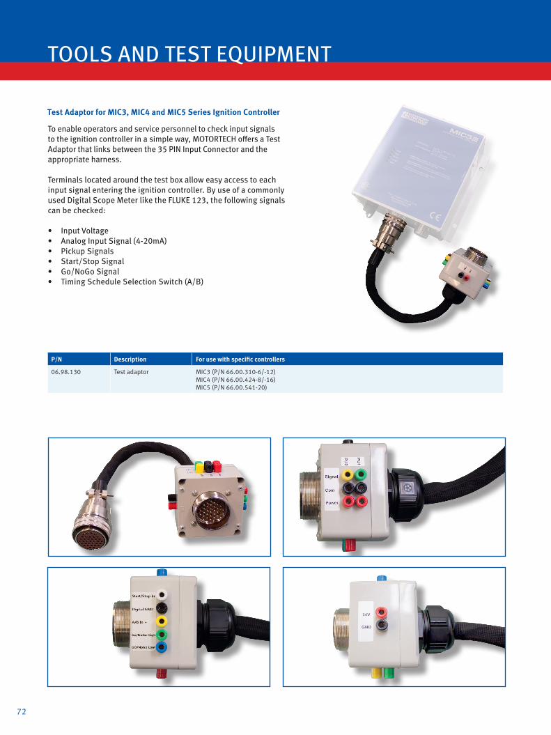
72
TOOLS AND TEST EQUIPMENT
To enable operators and service personnel to check input signals to the ignition controller in a simple way, MOTORTECH offers a Test Adaptor that links between the 35 PIN Input Connector and the appropriate harness.
Terminals located around the test box allow easy access to each input signal entering the ignition controller. By use of a commonly used Digital Scope Meter like the FLUKE 123, the following signals can be checked:
• Input Voltage• Analog Input Signal (4-20mA)• Pickup Signals • Start/Stop Signal• Go/NoGo Signal• Timing Schedule Selection Switch (A/B)
P/N Description For use with specific controllers
06.98.130 Test adaptor MIC3 (P/N 66.00.310-6/-12)MIC4 (P/N 66.00.424-8/-16) MIC5 (P/N 66.00.541-20)
Test Adaptor for MIC3, MIC4 and MIC5 Series Ignition Controller

73
MOTORTECH TIMING LIGHTScopeLite
The self-powered ScopeLite is designed to work with fully shielded ignition systems. A special clamp picks up the small trigger signal through the braid of conventional or MOT-Blues shielded high tension leads. The signal is processed by the timing light and via LED technology a sequence of flashes is generated.On applications where MOTORTECH flange ignition coils with diagnostic interface are used, the ScopeLite can be attached directly to the BNC connector of the ignition coil.
Even on applications with integral or standard flange ignition coils, the clamp can be attached to the shielded primary lead.When timing is checked on engines with non-shielded high tension leads, a selector switch needs to be pushed which then steps down sensitivity. The automatic time based shut-off function saves the 2 built in 9 V batteries in case the operator forgets to turn off power.
Make it easy and safe for the operator!
Conversion 1 inch = 25,4 mm / 1 foot = 0,3 m
ScopeLite – MOTORTECH Timing Light
P/N Description
06.98.100-200 ScopeLite LED timing light, incl. clamp, 200 in. standard connecting lead and carrying case
Connecting leads (Standard and Non Standard Lengths1))
P/N Description Length
06.90.104-100 ScopeLite connecting lead 100 in.
06.90.104-200 ScopeLite connecting lead 200 in.
06.90.104-300 ScopeLite connecting lead 300 in.
06.90.104-400 ScopeLite connecting lead 400 in.
06.90.104-600 ScopeLite connecting lead 600 in.
1) If non standard length is required, please order separately from above chart.
Use with MOT-Blues shielded high tension leads Use with conventional shielded high tension leads Use with MOTORTECH flange ignition coils with diagnostic interface or with shielded primary lead.

74
TOOLS AND TEST EQUIPMENT
Digital Protractor The digital protractor is a compact rotational angle measuring tool. The unit is equipped with magnets for easy and flexible installation on flywheel, camshaft, pulley or any other rotating shaft gear.
1 2
Conversion 1 inch = 25,4 mm / 1 foot = 0,3 m
Timing Light – Conventional Style
P/N Description Length
06.98.043-10 Timing light 3.0 m / 10.0 ft.
06.98.043-30 Timing light 10.0 m / 30.0 ft.
Digital Protractor
P/N Description
06.98.096 Digital protractor
High Tension Lead Removal Tool for MAN® Gas Engines
P/N Description
44.99.918 High tension lead removal tool for MAN® gas engines
Installation Tool for Reluctor PinP/N Description
44.99.011 Installation tool for reluctor pin P/N 06.80.104
Workshop Equipment
P/N Figure Description
06.05.903-1 1 Spark plug test stand for M14, M18 and 7/8 in. spark plugs
06.05.904-1 2 Engine simulator with 24 ignition coil rack

75
1 2 3
5 6 7 8
4
9
Harness Connector Assembly Tools
P/N Figure Description
06.98.011 4 Crimping tool for stainless steel wire studs
06.98.017 1 Extraction tool for ITT® contacts „16S“
06.98.046 7 Installation tool for MIL style connector pins
06.98.051 6 Removal tool for MIL style connector pins
High Tension Lead Assembly Tools
P/N Figure Description
06.98.011 4 Crimping tool for stainless steel wire studs
06.98.013 5 Crimping tool for P/N 06.80.116
06.98.019 2 Assembly tool for P/N 06.98.109
06.98.047 3 Crimping tool for P/N 06.80.126 (crimping tool insert P/N 06.98.048 already included)
06.98.048 8 Crimping tool insert for P/N 06.98.047 to crimp terminal P/N 06.80.126
06.98.050 9 Crimping tool insert for P/N 06.98.047 to crimp terminal P/N 22.85.802 and P/N 22.85.803

76
SPARK PLUGS AND ACCESSORIES
MOTORTECH Extended Barrel Spark Plugs
For certain applications extended barrel plugs are required. For example when the operator cannot get a conventional spark plug down the narrow spark plug well, he will need a special product that allows him to torque the plug from the top end. MOTORTECH offers an improved product to the market. Several of the known problems of products made by competitors are eliminated.
Besides an increase in reliability the spark plug run time nee-ded to be extended. To achieve this, MOTORTECH uses base plugs with Iridium alloy (J-Type) or Nickel/Aluminum alloy (X-Type) on center & ground electrode. MOTORTECH extended barrel spark plugs can be ordered in different lengths, termi-nal styles or with an integrated spark plug lead.
The “S2-Type” has a 3/4 in. male thread and used to be called the AIRCRAFT
STYLE spark plug. This spark plug is designed to
be connected to a shiel-ded high tension lead..
The “DCP-Type” has a female thread to adapt to
a short integral ignition coil. This combination is
popular in some applica-tions, where customers have had bad experien-ces with shielded high
tension leads.
The “C-Type” is an exten-ded barrel plug that has a conventional ceramic
insulator on the top end. This allows the use of a
standard spark plug boot. Preferable a connector
that includes a 5 kΩ resis-tor to suppress the RFI.
Features• No more trapped air in the extension barrel• No more condensation• No internal flash over• Built in ceramics• High dielectric strength• Rigid welds
MOTORTECH EXTENDED SPARK PLUGSXT-Plugs
The J-Type ground electrode ensures better combustion, particularly on lean burn gas engines.
The alternative X-Type double-stage electrodes are ideally suited for slow-speed gas engines.
MOTORTECH XT-PLUGS are available with three different termi-nal styles to be connected directly to a high tension lead or a short integral ignition coil.

Conversion 1 inch = 25,4 mm / 1 foot = 0,3 m
Recommended Tightening Torque1)
Thread Size Tightening Torque (Cast Iron Head)
M14 x 1.25 30-40 Nm 22-30 lb-ft
M18 x 1.5 50-60 Nm 37-44 lb-ft
7/8-18 70-80 Nm 52-59 lb-ft1) Please observe the tightening torques rendered by each engine manufacturer.
E C
B
MOTORTECH XT Plugs – Specification Table
A A AF
D
A Spark Plug Style
C C Typ - for use with high tension lead
DCP DCP Type - for use with integral ignition coil
S2 S2 Type - for use with shielded high tension lead
A B C DP/N E F-
B C D Thread Size Thread Reach Electrode Design
B4 1 2 M14x1.25 0.500 in. J-Type
B4 3 2 M14x1.25 0.750 in. J-Type
B8 1 1 M18x1.5 0.500 in. X-Type
B8 1 2 M18x1.5 0.500 in. J-Type
B8 3 1 M18x1.5 0.750 in. X-Type
B8 3 2 M18x1.5 0.750 in. J-Type
B8 4 2 M18x1.5 0.875 in. J-Type
B8 5 2 M18x1.5 1.000 in. J-Type
B7 3 1 7/8-18 0.750 in. X-Type
B7 3 2 7/8-18 0.750 in. J-Type
E Extended Barrel Length1)
BEX6 6 in.
BEX8 8 in.
BEX10 10 in.
BEX12 12 in.
BEX16 16 in.
F Electrode Gap
010 0.010 in. / 0.25 mm
012 0.012 in. / 0.30 mm
014 0.014 in. / 0.35 mm
1) Other barrel lenghts available on request.
optional
77

78
SPARK PLUGS AND ACCESSORIES
XTL-PlugsMOTORTECH EXTENDED SPARK PLUGS
5A = ALTRONIC® style; 5B = BENDIX® style; 5C = MOTORTECH style
6 8 975*42 31a1
SPARK PLUGS AND ACCESSORIES
For non-shielded Applications
Based on the concept of the extended barrel spark plugs, MOTORTECH offers another style of spark plug. MOTORTECH XTL-PLUGS are manufactured with an integrated 7 mm spark plug lead, which allows a direct connection to an externally mounted ignition coil.
MOTORTECH XTL-PLUGS can be ordered with different barrel and lead lengths, different lead outputs from the barrel and a wide range of ignition coil connectors. This guarantees a custom-made spark plug which definitely fits your application.
D
F
B
A
C
H
E
G
F
G
Available Connectors to Ignition Coil

Conversion 1 inch = 25,4 mm / 1 foot = 0,3 m
79
MOTORTECH XTL-Plugs for non-shielded Applications – Specification Table
A B C Thread Size Thread Reach Electrode Design
B4 1 2 M14x1.25 0.500 in. J-Type
B4 3 2 M14x1.25 0.750 in. J-Type
B8 1 1 M18x1.5 0.500 in. X-Type
B8 1 2 M18x1.5 0.500 in. J-Type
B8 3 1 M18x1.5 0.750 in. X-Type
B8 3 2 M18x1.5 0.750 in. J-Type
B8 4 2 M18x1.5 0.875 in. J-Type
B8 5 2 M18x1.5 1.000 in. J-Type
B7 3 1 7/8-18 0.750 in. X-Type
B7 3 2 7/8-18 0.750 in. J-Type
D Extended Barrel Length1)
BEX6 6 in.
BEX8 8 in.
BEX10 10 in.
BEX12 12 in.
BEX16 16 in.
E Lead Output from Extended Barrel
A 90°
B 180°
F Lead length1)
8 8 in.
10 10 in.
12 12 in.
14 14 in.
16 16 in.
18 18 in.
G Connector to Ignition Coil
1 Non CSA ALTRONIC® Style - male, 180°
1A Non CSA ALTRONIC® Style - female, 180°, with spreading adaptor
2 Non CSA MOTORTECH Style - M6, 90°
3 Non CSA ALTRONIC® Style - male, 180°
4 Non CSA ALTRONIC® Style - female, 90°
5A CSA ALTRONIC® Style - Externally Mounted - 3/4-20 UNEF
5B CSA BENDIX® Style - Externally Mounted - 3/4-20 UNEF
5C CSA MOTORTECH Style - Externally Mounted - 1-20 UNEF
6 Non CSA ALTRONIC® Style - male, 90°
7 Non CSA New MOTORTECH Style - M6, 180°
8 Non CSA ALTRONIC® Style - female, 90°
9 Non CSA FM®-Style - male - no boot
10 CSA MOTORTECH Style - Igniter Assy, 180°
H Electrode Gap
010 0.010 in. / 0.25 mm
012 0.012 in. / 0.30 mm
014 0.014 in. / 0.35 mm
1) Other barrel and lead lenghts available on request.
A B C DP/N E F -G H-
Recommended Tightening Torque1)
Thread Size Tightening Torque (Cast Iron Head)
M14 x 1.25 30-40 Nm 22-30 lb-ft
M18 x 1.5 50-60 Nm 37-44 lb-ft
7/8-18 70-80 Nm 52-59 lb-ft1) Please observe the tightening torques rendered by each engine manufacturer.
optional

80
SPARK PLUGS AND ACCESSORIES
For shielded Applications
MOTORTECH XTL-PLUGS are also available for shielded appli-cations. To meet CSA requirements, this type of spark plug is fitted with an integrated and specially designed spark plug lead. This is also known from MOTORTECH´s MOT-Blues high tension leads. The multi layer design ensures that no humidity can be trapped in the lead.
MOTORTECH XTL-PLUGS can be ordered with different barrel and lead lengths and suitable ignition coil connectors, to allow direct connection to a shielded ignition coil. This guarantees a custom-made spark plug which definitely fits your application.
SPARK PLUGS AND ACCESSORIES
XTL-PlugsMOTORTECH EXTENDED SPARK PLUGS
SPARK PLUGS AND ACCESSORIES
EG
C
B
D
I
FH
The specially designed spark plug lead consists of a multi layer design:
• Nickel plated copper core• 2 layers of silicone• Stainless steel braid• Silicone jacket

MOTORTECH XTL-Plugs for shielded Applications – Specification Table
5*
81
A Spark Plug Style
I Shielded Application
B C D Thread Size
Thread Reach Electrode Design
B4 1 2 M14x1.25 0.500 in. J-Type
B4 3 2 M14x1.25 0.750 in. J-Type
B8 1 1 M18x1.5 0.500 in. X-Type
B8 1 2 M18x1.5 0.500 in. J-Type
B8 3 1 M18x1.5 0.750 in. X-Type
B8 3 2 M18x1.5 0.750 in. J-Type
B8 4 2 M18x1.5 0.875 in. J-Type
B8 5 2 M18x1.5 1.000 in. J-Type
B7 3 1 7/8-18 0.750 in. X-Type
B7 3 2 7/8-18 0.750 in. J-Type
E Extended Barrel Length1)
BEX6 6 in.
BEX8 8 in.
BEX10 10 in.
BEX12 12 in.
BEX16 16 in.
F Lead Output from Extended Barrel
B 180°
G Lead length1)
8 8 in.
10 10 in.
12 12 in.
14 14 in.
16 16 in.
18 18 in.
H Connector to Ignition Coil
5A CSA ALTRONIC® Style - Externally Mounted - 3/4-20 UNEF
5B CSA BENDIX® Style - Externally Mounted - 3/4-20 UNEF
5C CSA MOTORTECH Style - Externally Mounted - 1-20 UNEF
I Electrode Gap
010 0.010 in. / 0.25 mm
012 0.012 in. / 0.30 mm
014 0.014 in. / 0.35 mm
1) Other barrel lenghts available on request.
A B C DP/N E F -G H- I
optional
Recommended Tightening Torque1)
Thread Size Tightening Torque (Cast Iron Head)
M14 x 1.25 30-40 Nm 22-30 lb-ft
M18 x 1.5 50-60 Nm 37-44 lb-ft
7/8-18 70-80 Nm 52-59 lb-ft1) Please observe the tightening torques rendered by each engine manufacturer.

82
SPARK PLUGS AND ACCESSORIES
MOTORTECH Bridge Plug
Modern gas engines are permanently operating under absolu-te extreme conditions with an effective mean pressure of more than 20 bar, with highly corrosive fuels (H2S) – simultaneous-ly demanding longer life periods. The MOTORTECH MBP1800 spark plug uses an innovative, highly solid electrode design.
Call MOTORTECH or your nearest MOTORTECH sales partner for information about the range of application.
MOTORTECH pre-chamber spark plugs are a cost-effective high performance solution for a wide variety of stationa-ry gas engines. They feature a rigid design for industrial purposes that guarantees a long service life. The innovative product optimizes combustion in the engine and improves efficiency and emission values.
Call MOTORTECH or your nearest MOTORTECH sales partner for information about the range of application.
MOTORTECH MPC Pre-Chamber Spark Plugs
P/N1) Description Thread Size Thread Reach Electrode Design Hex Equivalent to
MPC1800 MPC spark plug M18x1.5 22.0 mm Pre-Chamber - PT/PT 7/8 in. 346-5123
MPC1900 MPC spark plug M18x1.5 22.0 mm Pre-Chamber - IR/PT 13/16 in.
1) MOTORTECH MPC spark plugs only available in packs of 4 pcs.
P/N1) Description Thread Size Thread Reach Electrode Design Hex Equivalent to
MBP1800 MBP spark plug M18x1.5 22.6 mm Bridge - IR/IR 7/8 in. FB78WW
1) MOTORTECH MBP spark plugs only available in packs of 4 pcs.
For the use with engines that have a pre-chamber *

83
For Operators who prefer to use a long integral ignition coil, MOTORTECH manufactures the dual threaded spark plugs.These are available in M14 and M18 thread sizes.
All plugs have iridium center and ground electrodes. For years these plugs have been successfully operated worldwide.
MOTORTECH ICP Spark Plugs with Dual Thread for use with Integral Ignition Coils
P/N1) Description Thread Size Thread Reach Electrode Design Hex Thread Size
Ignition Coil Equivalent to
ICPB412 ICP spark plug M14x1.25 0.500 in. J-Type - IR/IR 15/16 in. 13/16-20 UNEF RTL85G / 9Y3985
ICPB432 ICP spark plug M14x1.25 0.750 in. J-Type - IR/IR 15/16 in. 13/16-20 UNEF RTN79G / 4W2256
ICPB812 ICP spark plug M18x1.5 0.500 in. J-Type - IR/IR 15/16 in. 13/16-20 UNEF RTM77N / 60999G
ICPB832 ICP spark plug M18x1.5 0.750 in. J-Type - IR/IR 15/16 in. 13/16-20 UNEF RTB77WPCC
1) MOTORTECH ICP spark plugs only available in packs of 4 pcs.

84
Key to high reliability
The DDI's key to long plug lifeDENSO has launched the latest generation of hardwearing spark plugs − the DENSO DOUBLE IRIDIUM (DDI) spark plug. DDI spark plug technology improves and extends the spark plug's lifespan and requires significantly less maintenance than competitor spark plugs. The DDI spark plug is particularly effective when used in biogas engines. Try DENSO DDI spark plugs today.
The DDI's key to long plug life
Convergence laser welding
Iridium alloy
360° Laser welding
Iridium alloy padElectrical
resistance welding Platinum alloy pad
DENSO's OEM expertise and commitment to innovation enables them to remain at the forefront of cutting-edge gas engine spark plug development. The unique and specialist technology used in the Iridium Saver and Iridium Saver Performer spark plugs range extends their lifespan, making them ideal for high-compression lean-burn engines. Iridium Saver and Iridium Per-former spark plugs also help to maximise engine performance and deliver extra durability. Because they require minimal main-tenance compared to standard plugs, Iridium Saver and Iridium Saver Performer spark plugs increase service interval times.
Platinum alloy pad
Cross Groove
Iridium alloy
360° Laser welding
The SAVER's key to long plug life

85
Spark Plug Type and Installation Dimension
1. Iridium pad without cross groove on center electrode and Platinum pad on ground electrode.
3. For vehicle
5. Iridium pad without cross groove on center electrode and Iridium pad on ground electrode.
1. Iridium pad with cross groove on center electrode and Platinum pad on ground electrode.
3. Iridium pad without cross groove on center electrode and Platinum pad on ground electrode.
5. Iridium pad without cross groove on center electrode and Iridium pad on ground electrode.
All D
ENSO
dat
a in
this
pag
e is
sup
plie
d by
DEN
SO. M
OTOR
TECH
pub
lishe
s th
is in
form
atio
n w
ithou
t lia
bilit
y or r
espo
nsib
ility
for i
ts c
onte
nt, i
nteg
rity a
nd a
ccur
acy.
M14
M18
Cross Reference
CHAMPION® STITT® ALTRONIC® BERU®
RN79G (0.015) 407XL / R407XL J1463DP
14R-3CPU / 14-3CPU / 14R-5DPU / 14R-4CDP GE3-1 GE3-5
14R-4CIU (Z187) / 14R-4CIU2 (Z215) / 14R-4DIU2 (Z258) / 14R-4DIU3 GE3-5
RN79G (0.020) 14R-4CIU (Z205) GE5-1
RC78PYP / RC78PYP15 14FR-4DPUO GK3-1
GK3-5RC78WYP15 14FR-4DIU
RL85G / RL15B 407L / R407L J1443DP 14R-5BPU / 14R-4ADP / 14R-5BIU GN3-1
RB77WPCC / KB77WPCC / RB77CC / PB78WPC
L1863IP 18GZ4-77 / 18GZ6-77-2 GI3-3 GI3-5 GI3-1
RB75N / RB75PP R807LL L1863B / L1863DP 18GZ20 GI3-3 GI3-5 GI3-1
RB75WPCC-1 18GZ5-77-2 GL3-3 GL3-5 GL3-1
RB76N / RB76PP R807LL 18GZ7 GI3-3 GI3-5 GI3-1
RM77N 807 / 827 / 847 / U827 / U847
L1843B18GZ22 GT3-1
RM77PP L1843IP
Specifications and Cross Reference
IG 13
Initial GapNo Norminal Value
3 0.3 mm
4 0.4 mm
5 0.5 mm
for Gas Engines
- A
Terminal DesignNo SPEC.
none solid
A with nut
( )
Spark Plug Type and Installation DimensionNo Thread Hex Size Reach
E
M 14 x 1.25
20.8 mm
19 mm
N 12.7 mm
K 16 mm 19 mm
L
M 18 x 1.5
20.8 mm
20.6 mm
I
22.2 mm
T 13.8 mm

86
SPARK PLUGS AND ACCESSORIES
Seat & Thread Reconditioner Use Seat & Thread Reconditioner to clean Cylinder Threads and Gasket Seats in one operation.
Installation & Service Kit for MOTORTECH XTL Spark Plugs
P/N DescriptionFor Spark Plug with
Thread Size Thread Reach
07.98.214-34 Installation & service kit for MOTORTECH XTL spark plugs M14x1.25 3/4 in.
Torque Wrench
P/N Supersedes Description Torque Drive
07.98.065 07.95.063 Torque wrench 10 to 100 Nm / 7.4 to 74 ft./lb. 1/2 in.
Extended Barrel Magnetic Spark Plug Sockets – Standard Versions
P/N1) Supersedes Description Hex Drive
07.99.022-1-L 07.99.021-L Magnetic spark plug socket 1 in. 1/2 in.
07.99.022-2-L 07.99.020-L Magnetic spark plug socket 15/16 in. 1/2 in.
07.99.022-3-L 07.99.019-L Magnetic spark plug socket 7/8 in. 1/2 in.
07.99.022-4-L 07.99.018-L Magnetic spark plug socket 13/16 in. 1/2 in.
07.99.022-5-L Magnetic spark plug socket 5/8 in. 1/2 in.
1) Standard barrel lengths („L“) = 6 in., 12 in., 16 in., 18 in. Other lengths available on request.
Extended Barrel Magnetic Spark Plug Sockets – Special Versions
P/N Supersedes Description Hex Drive
07.99.022-3-36 Magnetic spark plug socket - NORDBERG® 7/8 in. 1/2 in.
07.99.022-6-6 Magnetic spark plug socket - MAN® 13/16 in. 1/2 in.
07.99.022-6-1 Magnetic spark plug socket - MAN®, LIEBHERR® 5/8 in. 1/2 in.
Spark Plug Socket for XTL Spark Plugs
P/N Supersedes Description Hex Drive
07.99.022-6-2 Spark plug socket 7/8 in. 1/2 in.
P/N Supersedes Description Thread Size Thread Reach
07.98.114-12 07.98.022 Seat & thread reconditioner M14 x 1.25 1/2 in.
07.98.114-34 07.98.023 Seat & thread reconditioner M14 x 1.25 3/4 in.
07.98.118-12 07.98.024 Seat & thread reconditioner M18 x 1.5 1/2 in.
07.98.118-34 07.98.025 Seat & thread reconditioner M18 x 1.5 3/4 in.
07.98.178-58 07.98.026 Seat & thread reconditioner 7/8-18 5/8 in.
07.98.178-78 07.98.026-1 Seat & thread reconditioner 7/8-18 7/8 in.
Extended Barrel Seat & Thread Reconditioners – 1/2 Inch Drive
P/N Supersedes Description Thread Size Thread Reach
07.98.114-12-BEX6 Seat & thread reconditioner, 6 in. length M14 x 1.25 1/2 in.
07.98.114-12-BEX12 Seat & thread reconditioner, 12 in. length M14 x 1.25 1/2 in.
07.98.114-34-BEX6 Seat & thread reconditioner, 6 in. length M14 x 1.25 3/4 in.
07.98.114-34-BEX12 Seat & thread reconditioner, 12 in. length M14 x 1.25 3/4 in.
07.98.118-12-BEX6 Seat & thread reconditioner, 6 in. length M18 x 1.5 1/2 in.
07.98.118-12-BEX12 Seat & thread reconditioner, 12 in. length M18 x 1.5 1/2 in.
07.98.118-34-BEX6 Seat & thread reconditioner, 6 in. length M18 x 1.5 3/4 in.
07.98.118-34-BEX12 Seat & thread reconditioner, 12 in. length M18 x 1.5 3/4 in.
07.98.178-58-BEX6 Seat & thread reconditioner, 6 in. length 7/8-18 5/8 in.
07.98.178-58-BEX12 Seat & thread reconditioner, 12 in. length 7/8-18 5/8 in.
07.98.178-78-BEX6 Seat & thread reconditioner, 6 in. length 7/8-18 7/8 in.
07.98.178-78-BEX12 Seat & thread reconditioner, 12 in. length 7/8-18 7/8 in.

87
Thread LubricantThis lubricant is non-metallic and non-conductive. Guarantees easy spark plug removal and prevents thread damage. Also for use with seat & thread reconditioner.
Spark Plug Cleaning KitCleaning of the spark plug electrode area by using a special glass bead blaster extends spark plug life and reduces purchasing cost.
P/N Description
07.98.718 Thread lubricant (4 oz / 115 g)
P/N Description
44.01.000 Spark plug cleaning kit
44.01.009 Blasting grit, bottle (1.0 kg)1)
1) Spark plug cleaning kit already includes a package of blasting grit.
Gaskets for Spark Plugs
P/N Description For Thread Size Quantity
02.85.015-100 Spark plug gasket M14x1.25 100 pcs.
02.85.016-100 Spark plug gasket M18x1.5 100 pcs.
02.85.017-100 Spark plug gasket 7/8-18 100 pcs.
Gaskets for MOTORTECH ICP Spark Plugs
P/N Description Quantity
75.90.295-100 Spark plug gasket, copper 100 pcs.
Gap Setting Tool for MOTORTECH MBP Spark Plug and J-Gap Spark Plugs
P/N Description
07.98.112-18 Spark plug gap setting tool for MOTORTECH MBP Spark Plug and J-Gap Spark Plugs with M18x1.5 thread
Gap Setting Tool
P/N1) Description
07.98.113 Gap setting tool incl. gap gauges 0.010 in./0.25 mm, 0.012 in./0.30 mm, 0.014 in./0.35 mm
1) Needs appropriate accessory kit in addition.
Accessory Kits for Gap Setting Tool
P/N1) Description
07.98.113-A Accessory kit for MOTORTECH X-type spark plugs
07.98.113-B Accessory kit for BERU® spark plugs Z283/Z351
1) Need to be ordered separately.

Bench Gap Setting Tool for CHAMPION® Spark Plugs with N-Type Electrode Design The more professional way to gap N-Type spark plugs is the bench mounted gapping tool. Each electrode is gapped individually.
1 2 3
P/N Supersedes Description Size
07.98.111 07.98.109 Bench gap setting tool
Includes:
07.98.100-18 Handwheel M18 x 1.5
07.98.100-78 Handwheel 7/8-18
07.98.101 Spreader
07.98.103-012 Gap gauge 0.012 in. / 0.30 mm
07.98.103-015 Gap gauge 0.015 in. / 0.38 mm
07.98.103-020 Gap gauge 0.020 in. / 0.51 mm
Gap Gauges for Bench Gap Setting Tool
P/N Supersedes Description Size
07.98.103-010 Gap gauge 0.010 in. / 0.25 mm
07.98.103-011 Gap gauge 0.011 in. / 0.28 mm
07.98.103-012 Gap gauge 0.012 in. / 0.30 mm
07.98.103-013 Gap gauge 0.013 in. / 0.33 mm
07.98.103-014 Gap gauge 0.014 in. / 0.35 mm
07.98.103-015 Gap gauge 0.015 in. / 0.38 mm
07.98.103-020 Gap gauge 0.020 in. / 0.51 mm
07.98.103-025 Gap gauge 0.025 in. / 0.64 mm
Gap Setting Tool for CHAMPION® Spark Plugs with N-Type Electrode Design
P/N Figure Supersedes Description Size
07.98.100-18 1 Handwheel M18 x 1.5
07.98.100-78 1 Handwheel 7/8-18
07.98.101 2 Spreader
07.98.102-010 3 Gap gauge 0.010 in. / 0.25 mm
07.98.102-013 3 Gap gauge 0.013 in. / 0.33 mm
07.98.102-015 3 Gap gauge 0.015 in. / 0.38 mm
07.98.102-020 3 Gap gauge 0.020 in. / 0.51 mm
07.98.102-025 3 Gap gauge 0.025 in. / 0.64 mm
Feeler Gauges
P/N Figure Supersedes Description Size
07.98.037 4 Feeler gauge clamp
07.98.059 5 Feeler gauge shim roll, 12.7 mm x 5.0 m 0.008 / 0.20 mm
07.98.034 5 Feeler gauge shim roll, 12.7 mm x 5.0 m 0.010 / 0.25 mm
07.98.035 5 Feeler gauge shim roll, 12.7 mm x 5.0 m 0.012 / 0.30 mm
07.98.036 5 Feeler gauge shim roll, 12.7 mm x 5.0 m 0.014 / 0.35 mm
88
4 5
SPARK PLUGS AND ACCESSORIES

NOTES
89

90
GAS ENGINE MANAGEMENT
MOTORTECH GAS ENGINE MANAGEMENTALL-IN-ONEFor monitoring, controlling, regulating and system protection. ALL-IN-ONE is an expandable controller for both single and multiple gen-sets operating in standby or parallel modes, espe-cially in cogeneration (CHP) and other complex applications.
Modular design (consisting of AIO controller and display unit) allows easy installation with the ability to add many different extension modules designed to suit individual customer requi-rements.
Built-in synchronizing, digital isochronous load sharing and air-fuel-ratio functions (requires additional dongle) allow a total integrated solution for gen-sets in standby, island, parallel or mains parallel. Native co-operation of up to 32 gen-sets is a standard feature.
AIO supports many standard ECU (electronic control unit) types and is specially designed to easily integrate new ones. A powerful graphic display with user-friendly controls allows any user whatever their ability to find the information they need. The display on the basic version is capable of display-ing graphical languages (e.g. Chinese).
Benefits
• Support of engines with ECU (Electronic control unit)
• Excellent configurability to match customer´s needs exactly
• Complete integrated gen-set solution incorpora-ting built-in PLC and signal sharing via CAN bus – minimum external components needed
• Many communication options – easy remote supervising and servicing
• Perfect price / performance ratio
• Gen-set performance log for easy problem tracing
• Air-Fuel-Ratio function for lean burn gas engine (requires additional hardware dongle)
Features
∙ CHP support (programmable PID loops and other built-in PLC functions)
∙ Support of engines with ECU (J1939, Modbus and other proprietary interfaces); alarm codes displayed in text form
∙ Automatic synchronizing and power control (via speed governor or ECU)
∙ Baseload, Import / Export, TempByPower
∙ Peak shaving
∙ Voltage and PF control (AVR)
∙ Generator measurement: U, I, Hz, kW, kVAr, kVA, PF, kWh, kVAhr
∙ Mains measurement: U, I, Hz, kW, kVAr, PF
∙ Selectable measurement ranges for AC voltages and currents – 120 / 277 V, 0–1 / 0–5 A
∙ Inputs and outputs configurable for various custo-mer needs
∙ Controller redundancy
∙ 2× RS232 / RS485 interface with Modbus protocol
∙ Support; Analog / GSM / ISDN / CDMA modem communication support; SMS messages; ECU Modbus interface; secondary RS485 converter is isolated
∙ Event-based history (up to 1000 records) with customer-selectable list of stored values; RTC; statistic values
∙ Integrated PLC programmable functions
∙ Interface to remote display units (3× AIO.NT- or AIO.Vision-display)
∙ USB 2.0 slave interface
∙ Dimensions 284 × 180 mm (front panel)
∙ Sealed to IP65
Integrated fixed and configurable protections
∙ 3 phase integrated generator protections (U + f)
∙ IDMT overcurrent + shortcurrent protection
∙ Overload protection
∙ Reverse power protection
∙ Earth fault protection
∙ 3 phase integrated mains protections (U + f)
∙ Vector shift protection
∙ All binary / analog inputs free configurable for various protection types: HistRecOnly / Alarm Only / Alarm + History indication / Warning / Off load / Slow stop / BreakerOpen&Cooldown / Shutdown / Shutdown override / Mains protect / sensor fail
∙ Phase rotation and phase sequence protection
∙ Additional 160 programmable protections configurable for any measured value to create customer-specific protections
∙ Application security

91
Generator∙ 3 Phase Monitoring∙ Over/Under Frequency∙ Over/Under Voltage∙ Interrupt free reverse synchronizing∙ Overload Protection∙ TempByPower load control∙ Reverse Power Protection∙ Load Surge Protection∙ Voltage and PF Control (AVR)
InteliPro∙ Designed to meet utility
protection requirements∙ Combines standard and
optional features∙ Advanced communications∙ Data/event logging
@
MCB GCB
LOAD
CAN1
CAN2
Modem∙ Remote Control∙ Internet Bridge
PC Monitoring Tool∙ Visualization∙ Programming
GSM∙ Active/Passive calls∙ SMS Service
AIN8 / BIN16/8 / I-AOUT8 Modules etc.∙ Digital inputs (80 max)∙ Digital outputs (48 max)∙ Analog inputs (84 max)∙ Analog outputs (33 max)∙ All kind of sensors usable (programmable)∙ Status LEDs for In- and outputs
RS 232 / RS 485∙ Modbus∙ Direct PC-Connection∙ Modem Connection∙ SMS Managment∙ Active Calls∙ Internet
up to 32 gensets
up to 32 devices
MainsPro∙ Protective functionalities∙ Free assignment of 5 relay outputs∙ 4 binary switches to remotely change
operation of the unit∙ Last trip recorded in order to provide
the evidence of cause of trip
InteliMains∙ Import/Export∙ Load Sharing∙ Power Plant Managment∙ Grid Monitoring∙ Running Hours Optimization
or
Main Circuit Breaker∙ Control∙ Reverse Synchronization∙ Grid Monitoring
Load Monitoring∙ Base Load∙ Import/Export∙ Peak Shaving
Generator Circuit Breaker∙ Control Synchronization
Engine Managment (ECU)∙ Speed Measurement/Control∙ Engine Monitoring and Protection∙ Exhaust Gas Temperature monitoring∙ Air/Fuel Ratio Control∙ Start/Stop Routines
Ethernet (only AIO.NTC-BB)

92
GAS ENGINE MANAGEMENT
AIO Controllers AIO.NTC ControllerP/N 63.50.104
Available Display Units for AIO.NTC Controllers
AIO.Vision (8.0 in.)P/N 63.50.101
AIO.Vision (17.0 in.)P/N 63.50.120
AIO.Vision (5.7 in.)P/N 63.50.105
AIO.NTP/N 63.50.103
Controllers
P/N Description
63.50.104 ALL-IN-ONE.NTC controller - universal Gen-Set controller (incl. AFR control1) and AirGate® technology)
63.50.104-HSS ALL-IN-ONE.NTC controller - universal Gen-Set controller P/N 63.50.104 incl. Plug-on module I-HSS-BIN6/10
63.50.082 Mini-ALL-IN-ONE controller - universal controller for small Gen-Sets (incl. AFR control2))
1) Requires hardware dongle P/N 63.50.061 or 63.50.062 for activation.2) Requires hardware dongle P/N 63.50.085 for activation (for applications up to 75 kWel only).
Display Units for ALL-IN-ONE.NTC Controllers
P/N Supersedes Description
63.50.105 ALL-IN-ONE.Vision display - 5.7 in. color display unit for ALL-IN-ONE.NT and ALL-IN-ONE.NTC controller
63.50.101 ALL-IN-ONE.Vision display - 8.0 in. color display unit for ALL-IN-ONE.NT and ALL-IN-ONE.NTC controller
63.50.120 63.50.115 ALL-IN-ONE.Vision display - 17.0 in. color touch display unit for ALL-IN-ONE.NT and ALL-IN-ONE.NTC controller
63.50.103 ALL-IN-ONE.NT display - detachable display unit for ALL-IN-ONE.NT and ALL-IN-ONE.NTC controller
Dongles
P/N Supersedes Description
63.50.061 Hardware dongle for ALL-IN-ONE.NTC controllers - AFR-PCM• Enables single isolated parallel with mains• Air/Fuel Ratio function for lean burn gas engines
63.50.062 Hardware dongle for ALL-IN-ONE.NTC controllers - AFR-PCLSM+PMS• Enables multiple isolated parallel or multiple paralell with mains • Power management operation (with CAN Bus)• Digital load sharing• Digital VAr sharing
63.50.085 Hardware dongle for Mini-ALL-IN-ONE - miniAFR-PCM• Enables single isolated parallel with mains• Air/Fuel Ratio function for lean burn gas engines• For applications up to 75 kWel only
• Optimizing number of running engines: Power management; kW, kVA or % load based
• Air/Fuel Ratio function for lean burn gas engines
Mini AIO ControllerP/N 63.50.082

93
IS-BIN 16/8P/N 63.50.005
IGS-PTMP/N 63.50.007
IAOUT8P/N 63.50.054
I-LB+P/N 63.50.075
IB-NTP/N 63.50.112
AIO.NTC ControllerP/N 63.50.104
IG-AVRiP/N 63.50.011
IG-AVRi transP/N 63.50.010-xxx
Sample Control Panel
I-AIN8P/N 63.50.092
Other Controllers
P/N Supersedes Description
63.50.064 Mains supervision controller - IM-NT
63.50.064-BTB Mains supervision controller Bus Tie Breaker- IM-NT BTB
63.50.064-MCB Mains supervision controller Main Circuit Breaker - IM-NT MCB
Accessories
P/N Supersedes Description
63.50.092 Analog input extension module - I-AIN8
63.50.002 Analog input extension module - IS-AIN8
63.50.093 Analog input extension module for thermocouples only - I-AIN8TC
63.50.108 Analog input extension module for thermocouples only - IS-AIN8TC
63.50.118 Extension module inputs/outputs - IO8/8
63.50.005 Binary input/output module, 16 inputs, 8 outputs - IS-BIN16/8
63.50.007 Analog/binary input/output module - IGS-PTM
63.50.007-HSS Analog/binary input/output module P/N 63.50.007 incl. plug-on module I-HSS-BIN8
63.50.011 AVR interface module - IG-AVRi
63.50.010-100 Power supply transformer for IG-AVRi module, 100-120 VAC, 50-60 Hz
63.50.010-230 Power supply transformer for IG-AVRi module, 230-480 VAC, 50-60 Hz
63.50.054 Analog output module - I-AOUT8
63.50.075 63.50.006 Modem extension unit - I-LB+
63.50.112 63.50.022 Internet bridge communication module - IB-NT
63.50.088 CAN repeater module - I-CR
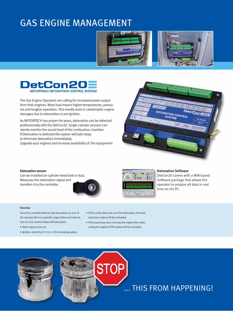
94
The Gas Engine Operators are calling for increased power output from their engines. More load means higher temperatures, pressu-res and tougher operation. This mostly ends in catastrophic engine damages due to detonation or pre ignition.
As MOTORTECH has proven for years, detonation can be detected professionally with the DetCon20. Single cylinder sensors con-stantly monitor the sound level of the combustion chamber. If Detonation is detected the system will take steps to eliminate detonation immediately.Upgrade your engines and increase availability of the equipment!
GAS ENGINE MANAGEMENT
MOTORTECH DETONATION CONTROL SYSTEMDetCon20
Function
Once the controller detects soft detonation on one of the sensors (this is a specific stage before real detona-tion occurs), several steps will take place:
∙ Alarm signal turns on
∙ Ignition retard by 0-5 V or 4-20 mA analog output.
∙ If this action does not cure the detonation, the load reduction output will be activated.
∙ If the load drop does not stop the engine from deto-nating the engine STOP output will be activated.
... THIS FROM HAPPENING!
STOP
Detonation sensorCan be installed on cylinder head bolt or stud. Measures the detonation signal and transfers it to the controller.
Detonation SoftwareDetCon20 comes with a WIN based Software package that allows the operator to analyze all data in real time on his PC.

95
USB
Up to 20 Detonation Sensors
CAN
Ignition Timing Control(0-5 VDC / 4-20 mA)
Power Supply 10-30 VDC
Binary OutputsAlarmLoad ReductionEngine Stop
ISU (Ignition Sensor Unit)(not required with MIC850, MIC3, MIC4, MIC5)
Signal from Ignition Coil #1 Cylinder
Ignition Controller
HMI Display
USBCAN
AIO Display
Anal
og O
utpu
t

96
GAS ENGINE MANAGEMENT
DetCon20 – Control Units
P/N Description
43.00.0201) DetCon20 control unit, 20 inputs, CSA, IP20
43.00.120 DetCon20 control unit, 20 inputs, CSA, includes ISU ignition sensor unit P/N 43.20.002
43.00.2202) DetCon20 control unit, 20 inputs, CSA
1) The control unit has to be installed in (CSA approved) control panel or enclosure.2) For use with MIC3, MIC4, MIC5 and MIC850 series ignition controllers. Ignition sensor unit is not required.
Detonation Sensor (1 per Cylinder required)
P/N Description
43.20.001 Detonation sensor w/o lead, 2 pole
Detonation Sensor Lead (1 per Detonation Sensor required)
P/N Description
43.30.004-60 Detonation sensor lead, 60 ft.
ISU Ignition Sensor Unit (1 per System required)
P/N Description
43.20.002 ISU ignition sensor unit1)
1) Not required if MIC3, MIC4, MIC5, MIC850 or DetCon20 control unit P/N 43.00.120 is used.

97
PowerView3 HMI Module
P/N Description
06.05.085 PowerView3 HMI module
06.05.087-F PowerView3 activation code for visualization of DetCon20 data1)
06.05.087-U PowerView3 activation code for visualization of DetCon20 data2)
1) Activation code has to be ordered separately with each PowerView3 HMI module. 2) Only available for upgrade of existing PowerView3 HMI module in the field.
MOTORTECH ENGINE INFORMATION MONITORPowerView3PowerView3 – HMI Module
The operating data of DetCon20 Detonation Control System will be completely visualized via HMI module (Human Ma-chine Interface). The overview sheet shows the relevant in-formation as engine knocking, knock intensity and status for activated load reduction or emergency shutdown of engine.The control keys guarantee simple navigation through different display pages and menus. All in all the PowerView3 HMI module is also able to provide error diagnostics on-site without requiring a laptop!
The PowerView3 is also available for data visualization of: • Ignition Control (MIC3, MIC4 and MIC5 series)• Temperature monitoring (available soon)
Sample Screens
DetCon OverviewScreen shows the most important operating data of the connected DetCon control unit.
Knocking IntensityVisualization of knocking intensity of each moni-tored cylinder. Different colors inform about the system status (Normal – Reduction – Critical).
Trending Knocking IntensityVisualization of knocking intensity trend data for each individual cylinder.

98
MOTORTECH stainless steel, vibration resistant rail assembly will withstand any harsh environment commonly found in oil & gas industry. Our proven design is made for engine manufacturers and the global aftermarket. Do not go low-tech and take the risk of engine down time because of equipment being under repair. Eliminate the need for constant rewiring, connector exchanges or straightening out weak and bent aluminum wiring rails.
MOTORTECH WIRING RAIL SYSTEMAlphaRail
GAS ENGINE MANAGEMENT
• Made of stainless steel which performs better than alumi-num in harsh environments (and where operators use any kind of equipment to hold or stand on)
• Made to perfectly fit the application• Rigid military style connectors are securely fastened into
the stainless steel
• Rails are filled with special foam to ensure that all wires are separated from ground and will not vibrate and eventually short out to ground
• Water proof design – built to last in uncovered environment• Repairable by MOTORETCH‘s assigned distributors in the
event of mechanically damage
Specification Charts:
www.motortech.de
- Configuration Help
02
In-Line Engine - One RailAlphaRail - Configuration Help
In-Line Engine - One Double RailAlphaRail - Configuration Help
In-Line Engine - Two RailsAlphaRail - Configuration Help
Specification Table C - Rev. 06/09
- Configuration Help
V-Engine - Two RailsAlphaRail - Configuration Help
V-Engine - Two Double RailsAlphaRail - Configuration Help
V-Engine - Four RailsAlphaRail - Configuration Help
03Specification Table C - Rev. 06/09
P/N 77.8A. B CD-E F
1
1234568
B = Specify Number of Sensors per Bank
A = Sensor-System
= Detonation Sensor
= Special Version= 2 Sensors= 3 Sensors= 4 Sensors= 5 Sensors= 6 Sensors= 8 Sensors
P/N 77.8 A.B CD-E F04
040607081011121314162733
CD = Distance between the Sensors
NOTE: Other code digits given by factory.
= 4" (102 mm)= 6" (152 mm)= 7" (178 mm)= 8" (203 mm)= 10" (254 mm)= 11" (279 mm)= 12" (305 mm)= 13" (330 mm)= 14" (356 mm)= 16" (406 mm)= 27" (686 mm)= 33" (838 mm)
- Specification Table
Specification Table C - Rev. 06/09
L1
B)Specify Number of Sensors per BankIf the distance between the first and last cylinder exceeds 114" (2,9 m) or more than 8 sensors per bank are needed,two separate sensor rails have to be specified. For example see Configuration I.AlphaRail - Specification Help
A) Sensor SystemAlphaRail - Specification Help
Detonation Sensor
Engine Make / Model No. of Cylinders
Specify Sensor Rail A Specify Sensor Rail B
Configuration I
05
CD) Distance between the SensorsAlphaRail - Specification Help
L1
4" (102 mm) 6" (152 mm) 7" (178 mm) 8" (203 mm)10" (254 mm)11" (279 mm)
12" (305 mm)13" (330 mm)14" (356 mm)16" (406 mm)27" (686 mm)33" (838 mm)
Other Length:
Special Version2 Sensors3 Sensors4 Sensors
5 Sensors6 Sensors8 Sensors
- Specification Help
Specification Table C - Rev. 06/09 08
P/N
77.41.117-577.41.117-1577.41.117-2577.41.117-50
Length
5' (1,5 m)15' (4,5 m)25' (7,5 m)50' (15 m)
Detonation Control - Harness to connect Sensor Rail and DetCon20AlphaRail - Harness
P/N
77.41.317-577.41.317-1577.41.317-2577.41.317-50
Length
5' (1,5 m)15' (4,5 m)25' (7,5 m)50' (15 m)
Detonation Control - Harness to connect Sensor Rail and DetCon20AlphaRail - Harness
- Harness & Sensor
Connector
180°180°180°180°
Connector
90°90°90°90°
L
L
Detonation Control - Lead to connect Detonation Sensor and Sensor RailAlphaRail - Sensor-Lead
P/N
43.30.016-1043.30.016-2043.30.016-3043.30.016-4043.30.016-60
Length
10" (254 mm)20" (508 mm)30" (762 mm)40" (1016 mm)60" (1524 mm)
Sensor
180°/2-polig180°/2-polig180°/2-polig180°/2-polig180°/2-polig L
Sensor Rail
180°/3-polig180°/3-polig180°/3-polig180°/3-polig180°/3-polig
P/N
43.20.001
Description
Detonation Sensor w/o lead - 180°/2-pole
Detonation SensorAlphaRail - Sensor
Specification Table C - Rev. 06/09
- Bracket Configuration & Accessories
10
Accessories - Please order separately!AlphaRail - Accessories
Specification Table C - Rev. 06/09
P/N: 75.10.096Bracket, 40x49 mm (Standard)
P/N: 75.10.097Flat Bar, 180° (Standard)
P/N: 75.10.120Flat Bar, 120°(alternative for 75.10.097)
Bracket Configuration - Please order separately!AlphaRail - Bracket Configuration
P/N: 15.07.134-13/4"-Flex Conduit
P/N: 15.07.231-13/4" -Adaptor, Junction Box to FlexConduit, 180°
NOTE: For packs of ten please add suffix -10 to part number.

99
AlphaRail – Wiring Rail
P/N Description
77.81.XXX-XX See specification sheet or consult factory for detailed specification.
Harness to connect Wiring Rail and DetCon20 Control Unit (1 per Rail required)
P/N Description Rail Connector Length
77.41.117-L Harness 17 pole pin, 180° „L“= 5/15/25/50 ft.
77.41.317-L Harness 17 pole pin, 90° „L“= 5/15/25/50 ft.
Lead to connect Detonation Sensor and Wiring Rail (1 per Sensor required)
P/N Description Sensor Connector Rail Connector Length1)
43.30.016-25 Sensor lead 2 pole socket, 180° 3 pole socket, 180° 25 in.
43.30.016-30 Sensor lead 2 pole socket, 180° 3 pole socket, 180° 30 in.
43.30.016-40 Sensor lead 2 pole socket, 180° 3 pole socket, 180° 40 in.
1) Other lengths available on request.
Detonation Sensor (1 per Cylinder required)
P/N Description
43.20.001 Detonation sensor w/o lead, 2 pole
Bracket Configuration
P/N1) Description
75.10.303 Bracket, 40x40 mm (Standard)
75.10.097 Flat bar, 180° (Standard)
75.10.120 Flat bar, 150°
75.10.280 Flat bar, 90°
1) For packs of ten please add suffix „-10“ to part number.
Accessories
P/N Description
15.07.134 Connecting flex conduit, 3/4 in.
15.07.231 Adaptor, 3/4 in., junction box to connecting flex conduit
06.05.075 Junction box

100
GAS ENGINE MANAGEMENT
X
MOTORTECH Actuator Replacement Kit for WAUKESHA® ESM Extender Engines
MOTORTECH ELECTRIC ESM EXT ACTUATORMOT-Actuator
• Drop in replacement
• Eliminates HEINZMANN® actuator
• Plug and play connection
• Does not require any
- ESM software adjustment
- or harness modification
• Mounting bracket, included
• Allows easy drop in installation
• Lever, included
• Simple connection to existing linkage
Actuator Replacement Kit for WAUKESHA® ESM Extender Engines
P/N Supersedes Description Equivalent to
63.04.175 Actuator Replacement Kit for WAUKESHA® ESM Extender Engines 214046

101
NOTES

102
SENSOR SYSTEMS
The stainless steel wiring rails which are water tight due to a well approved foaming process, offer an easy and fast installation of accessory control systems such as• Pyrometer/temperature control • Gas valve systems
With individual outlet port connectors, the sensors can be in-dividually connected and easily wired to the rail. A disconnect able main harness routs all sensors to one main control unit or individual wiring boxes.
Details on the Pyrometer/ Thermocouple Wiring Rail:• Up to 10 exhaust sensor inputs per rail• Additionally 2 turbo charger thermocouples• All sensors need to be NiCr-Ni – Type K sensors• Made of stainless steel which performs better than
aluminum in harsh environments (and where operators use any kind of equipment to hold or stand on)
• Made to perfectly fit the application• Rigid military style connectors are securely fastened into
the stainless steel• Rails are filled with special foam to ensure that all wires are
separated from ground and will not vibrate and eventually short out to ground
• Water proof design – built to last in uncovered environment• Repairable by MOTORETCH‘s assigned distributors in the
event of mechanically damage
General Details:• Low voltage signals can be grouped in one rail. It is not
recommended to have low and high voltage signals in one rail. In this case, detonation sensors and thermocouple leads match perfectly.
• Ignition and gas valve control wire work together well.
MOTORTECH WIRING RAIL SYSTEMAlphaRail

103
Conversion: 1 inch = 25,4 mm / 1 foot = 0,3 m
Wiring Rail
P/N Description
77.82.XXX-XX See specification sheet or consult factory for detailed specification.
Harness to connect Wiring Rail (1 per Rail required)
P/N Description Rail Connector Length
77.42.125L Harness 25 pole socket, 180° „L“= 5/15/25/50 ft.
77.42.325-L Harness 25 pole socket, 90° „L“= 5/15/25/50 ft.
Thermocouples with Lead and Rail Connector (1 per Cylinder required)
P/N Description Version Rail Connector Length
56.01.090-L / -K1) Thermocouple, Type K 90° 3 pole pin, 180° „L“= 10/20/25/30/40/60 in.
56.01.180-L / -K1) Thermocouple, Type K 180° 3 pole pin, 180° „L“= 10/20/25/30/40/60 in.
1) Comes with loose connector and 177 in. lead length.
Bracket Configuration
P/N1) Description
75.10.303 Bracket, 40x40 mm (Standard)
75.10.097 Flat bar, 180° (Standard)
75.10.120 Flat bar, 150°
75.10.280 Flat bar, 90°
1) For packs of ten please add suffix „-10“ to part number.

104
SENSOR SYSTEMS
Thermocouple Rails
P/N Description Equivalent to
D211359G-MOT Thermocouple wiring rail kit with 8 ft. harness to junction box D211359G
77.75.068-50 Thermocouple wiring rail kit with 50 ft. harness for direct wiring
77.75.066 Thermocouple wiring rail kit with 8 ft. harness and connector to ESM wiring system 214036D
Spare Parts
P/N Description Lead Length For Use with Equivalent to
56.01.094-23 Thermocouple, NiCrNi, 90° 23ft. D211359G-MOT, 77.75.066 211288S
56.01.094-59 Thermocouple, NiCrNi, 90° 59ft. 77.75.068-50
Optional Parts
P/N Description Required Quantity Equivalent to
64.40.038 Swagelok® fitting, 1/4 in., outer thread 1/4 in. NPT 14 pcs. per rail kit 194929
Upgrade your Workhorse to new Thermocouple Rails for WAUKESHA® 12 Cylinder VHP Engines
MOTORTECH now offers a series of different Thermocouple Rail Upgrade Kits.The new rails are installed in the “Vee” or on the side of the engine. These rail kits replace any prior system if installed.
• Direct replacement for WAUKESHA® Thermocouple Conduit Assembly
• Available in different versions
• Prefabricated system guarantees easy exchange and installation
• Serviceable stainless steel wiring rail, no foam inside
• 14 thermocouples, Type K (NiCrNi), 90°
• Harness with flex conduit and J-Box or a large connector to fit the ESM
• Rail mounting brackets included in each kit
Stainless Steel Wiring Rail Assembly
Thermocouples, Type K, NiCrNi, 90°
Harness with flex conduit and fitting

105
Thermocouple for CATERPILLAR® G3500 Series Gas Engines
P/N1) Description Version Connector Length Equivalent to
56.01.092-28 Thermocouple, Type K 90° 2 pole pin, 180° 28.00 in. 2149591, 3832989
1) Other lengths available on request.
Thermocouple with Lead and Rail Connector for AlphaRails – For CUMMINS® QSK60G and QSV81/91G
P/N1) Description Version Rail Connector Length Equivalent to
56.01.091-25 Thermocouple, Type K 90° 3 pole pin, 180° 25.00 in.
1) Other lengths available on request.
Thermocouples for DEUTZ®/MWM® Gas Engines
P/N Description Engine Model
1229 6754 Thermocouple 616 series
1229 9487 Thermocouple 616 series
1229 3602 Thermocouple 620 series
1229 9387 Thermocouple 620 series
1232 2279 Thermocouple 2016 series
Thermocouples for WAUKESHA® Gas Engines
P/N Description Version Connector Length Equivalent to
56.01.005-42 Thermocouple, Type-K 180° 3 pole socket, 180° 42.00 in. 295962
56.01.005-53 Thermocouple, Type-K 180° 3 pole socket, 180° 53.00 in. 295962A
56.01.005-70 Thermocouple, Type-K 180° 3 pole socket, 180° 70.00 in. 295962B
56.01.005-81 Thermocouple, Type-K 180° 3 pole socket, 180° 81.00 in. 295962C
Thermocouples for AlphaRail Wiring Rail System for Temperature Control
P/N Description Version Rail Connector Length Equivalent to
56.01.090-10 Thermocouple, Type K 90° 3 pole pin, 180° 10.00 in.
56.01.090-20 Thermocouple, Type K 90° 3 pole pin, 180° 20.00 in.
56.01.090-25 Thermocouple, Type K 90° 3 pole pin, 180° 25.00 in.
56.01.090-30 Thermocouple, Type K 90° 3 pole pin, 180° 30.00 in.
56.01.090-40 Thermocouple, Type K 90° 3 pole pin, 180° 40.00 in.
56.01.090-60 Thermocouple, Type K 90° 3 pole pin, 180° 60.00 in.
56.01.090-K1) Thermocouple, Type K 90° 3 pole pin, 180° 177.00 in.
56.01.180-10 Thermocouple, Type K 180° 3 pole pin, 180° 10.00 in.
56.01.180-20 Thermocouple, Type K 180° 3 pole pin, 180° 20.00 in.
56.01.180-25 Thermocouple, Type K 180° 3 pole pin, 180° 25.00 in.
56.01.180-30 Thermocouple, Type K 180° 3 pole pin, 180° 30.00 in.
56.01.180-40 Thermocouple, Type K 180° 3 pole pin, 180° 40.00 in.
56.01.180-60 Thermocouple, Type K 180° 3 pole pin, 180° 60.00 in.
56.01.180-K1) Thermocouple, Type K 180° 3 pole pin, 180° 177.00 in.
1) Comes with loose connector and 177 in. lead length.

106
SENSOR SYSTEMS
UEGO Oxygen Sensor
P/N Figure Description Connector Length Equivalent to
19.60.007 3 UEGO oxygen sensor 8 pole pin, 180° 15.75 in. DL08311001
19.71.013 UEGO oxygen sensor lead 8 pole socket, 180° 79.00 in. DL08311003
SensorsFor several years MOTORTECH offers Oxygen sensors that can be used as replacements for the OEM part. Shielded and unshielded versions can be selected.To increase life time of these critical sensors, there is also a stain-less steel hub available that is welded into the exhaust pipe.
A heat shield can be screwed on top. This way the sensor does reach directly into the exhaust gas stream with all its depo-sits and the heat shield protects the sensor against transient temperature from the hot exhaust manifold.
Oxygen Sensors for CATERPILLAR® G3400 and G3500 Series Gas Engines
P/N Figure Description Connector Length Equivalent to
19.60.027 1 Oxygen sensor, non shielded 6 pole pin, 180° 10.00 in. 196-5391
19.60.029 2 Oxygen sensor, shielded 6 pole pin, 180° 51.00 In. 141-2494
Oxygen Sensor Harness for WAUKESHA®
P/N Figure Description Connector Length Equivalent to
06.30.110 Oxygen sensor harness 9 pole pin, 180° 90.00 in. A740735
Conversion: 1 inch = 25,4 mm / 1 foot = 0,3 m
1 2 3

107
Conversion: 1 inch = 25,4 mm / 1 foot = 0,3 m
Oxygen Sensor – Heated
P/N Description Connector Length Equivalent to
19.60.015 Oxygen sensor, heated 4 pole pin, 180° 0.35 m
19.71.015-2 Oxygen sensor lead 4 pole socket, 180° 2.00 m
19.71.015-3 Oxygen sensor lead 4 pole socket, 180° 3.00 m
19.71.015-15 Oxygen sensor lead 4 pole socket, 180° 15.00 m
19.71.015-30 Oxygen sensor lead 4 pole socket, 180° 30.00 m
Oxygen Sensor – Non Heated
P/N Description Connector Length Equivalent to
19.60.004 Oxygen sensor, non heated 2 pole pin, 180° 0.35 m
19.71.004-32 Oxygen sensor lead 2 pole socket, 180° 32.00 ft.
19.71.004-50 Oxygen sensor lead 2 pole socket, 180° 50.00 ft.
19.71.004-100 Oxygen sensor lead 2 pole socket, 180° 100.00 ft.
Accessories for Oxygen Sensors
P/N Description Equivalent to
19.60.022 Heat shield
19.60.023 Weld hub
MAP – Manifold Absolute Pressure Sensor
P/N Description Connector Length Equivalent to
19.60.002 MAP sensor 3 pole socket 6910-314
19.71.002 MAP sensor lead 3 pole pin, 180° 8.00 m DL08220604
MAP – Manifold Absolute Pressure Sensors
P/N Supersedes Description Thread Pressure Range Equivalent to
56.01.001 MAP sensor G1/4 in. 0 - 10,0 bar
56.01.002 MAP sensor G1/4 in. 0 - 6,0 bar
56.01.010 MAP sensor G1/4 in. 0 - 16,0 bar
56.02.017 56.02.016 MAP sensor G1/4 in. 0 - 3,0 bar
MAT – Manifold Air Temperature Sensors
P/N Supersedes Description Thread Fitting Length Equivalent to
56.01.004 56.01.021 MAT sensor G1/2 in. 50 mm
56.01.011 MAT sensor G1/2 in. 75 mm
56.01.017 MAT sensor G1/2 in. 100 mm

108
GAS REGULATIONGAS REGULATION
VariFuel2 − Air/Fuel Ratio MixerThe VariFuel2 is a high-tech variable venturi type mixer that can constantly adjust to any fuel changes and allows the engi-ne to operate at its most efficient point.Series 100, 140, 200 and 250 are available for engines up to 1 MW. Coupled to an air/fuel ratio controller, lean-burn or stoichiometric, it precisely regulates the mixture. Very popular in applications where fuel quality constantly changes. Available for nearly all gas qualities: Natural gas, biogas, landfill gas, wood gas, mine gas.High precision stepper motor drive with exclusive reprogram-mable controller board. Totally flexible cross section adjust-ment with various flow bodies and flexible inlet and outlet configuration.
MOTORTECH AIR/FUEL RATIO MIXERVariFuel2
Stepper Motor Card Flow Bodies Gas Inlet Flanges Outlet Flange Kits

109
System Overview
VariStepMOTORTECH STEPPER MOTOR CARD
MOTORTECH AIR/FUEL RATIO MIXERVariFuel2
MOTORTECH INTEGRATED THROTTLE BODYITB
MOTORTECH SPEED CONTROLLERSC100VariStep
MOTORTECH STEPPER MOTOR CARD
Required Accessories
1 VariFuel22 Flow body3 Gas inlet flange4 Wiring harness5 VariStep Stepper Motor Card
Accessories
A Gastrain (ZERO Pressure Regulator required)B Integrated Throttle BodyC Wiring HarnessD VariStep Stepper Motor CardE SC100 Speed Controller
Description
F EngineG Air filter
Gas
Ball Valve Double Safey Valve
Gas FilterZERO Pressure
Regulator
Air
G
C
B
F
4
5
3
A
1
D
E
2

110
Please consult the factory or your nearest MOTORTECH® Sales Partner to get the correct VariFuel2 series specified for your engine application. Question Form to identify your suitable VariFuel2 Air / Fuel Ratio Mixer:
In-line engine V-engineCylinder arrangement
2 stroke 4 strokeStroke
Yes No Turbocharged engine
Yes No Intercooler
Engine manufacturer Series
Fuel consumptionFuel
Engine model Nominal speed (rpm)
Air consumption
Calorific value
Air ratio λ
Features
VariFuel2 Series 100-60 140-80 200-120 250-150
Air requirement 100-650 m³/h 200-1300 m³/h 500-3200 m³/h 1800-5200 m³/h
Available flow body sizes 23.0 - 55.0 mm in steps of 2.5 mm
23.0 - 72.5 mm in steps of 2.5 mm
23.0 - 107.5 mm in steps of 2.5 mm
23.0 - 110.0 mm in steps of 2,5 mm
Flexible inlet and outlet configuration x x x x
Driven by timing belt x x x x
Number of gas pressure gauge connections 1 1 1 1
Number of air pressure gauge connections 1 1 1 1
Hose connection for air inlet x x x x
Various flange connections for outlet x x x x
Various flange connections for gas inlet x x x x
The centrical flow body is fixed with 3 profiles. Their numerous small gas inlets provide an optimum mixture of gas and circulating air, granting a constant level of homogenization of the air-fuel mix.
x x x x
GAS REGULATION

111Conversion: 1 inch = 25,4 mm / 1 foot = 0,3 m
VariFuel2 Air/Fuel Ratio Mixer – with Digital Stepper Motor
P/N Supersedes Description
30.45.100-60D 30.45.100-50D VariFuel2 air/fuel ratio mixer - series 100-60
30.45.140-80D 30.45.140-65D VariFuel2 air/fuel ratio mixer - series 140-80
30.45.200-120D 30.45.200-100D VariFuel2 air/fuel ratio mixer - series 200-120
30.45.250-150D VariFuel2 air/fuel ratio mixer - series 250-150
VariFuel2 Air/Fuel Ratio Mixer – Manually Adjustable
P/N Supersedes Description
30.45.100-60M 30.45.100-50M VariFuel2 air/fuel ratio mixer - series 100-60
30.45.140-80M 30.45.140-65M VariFuel2 air/fuel ratio mixer - series 140-80
30.45.200-120M 30.45.200-100M VariFuel2 air/fuel ratio mixer - series 200-120
30.45.250-150M VariFuel2 air/fuel ratio mixer - series 250-150
Flow Bodies
P/N Description Diameter 100-60D/M 140-80D/M 200-120D/M 250-150D/M
31.01.720-23.0-3 Flow body 23,0 mm x x x x
31.01.720-25.0-3 Flow body 25,0 mm x x x x
31.01.720-27.5-3 Flow body 27,5 mm x x x x
31.01.720-30.0-3 Flow body 30,0 mm x x x x
31.01.720-32.5-3 Flow body 32,5 mm x x x x
31.01.720-35.0-3 Flow body 35,0 mm x x x x
31.01.720-37.5-3 Flow body 37,5 mm x x x x
31.01.720-40.0-3 Flow body 40,0 mm x x x x
31.01.720-42.5-3 Flow body 42,5 mm x x x x
31.01.720-45.0-3 Flow body 45,0 mm x x x x
31.01.720-47.5-3 Flow body 47,5 mm x x x x
31.01.720-50.0-3 Flow body 50,0 mm x x x x
31.01.720-52.5-3 Flow body 52,5 mm x x x x
31.01.720-55.0-3 Flow body 55,0 mm x x x x
31.01.720-57.5-3 Flow body 57,5 mm x x x
31.01.720-60.0-3 Flow body 60,0 mm x x x
31.01.720-62.5-3 Flow body 62,5 mm x x x
31.01.720-65.0-3 Flow body 65,0 mm x x x
31.01.720-67.5-3 Flow body 67,5 mm x x x
31.01.720-70.0-3 Flow body 70,0 mm x x x
31.01.720-72.5-3 Flow body 72,5 mm x x x
31.01.720-75.0-3 Flow body 75,0 mm x x
31.01.720-77.5-3 Flow body 77,5 mm x x
31.01.720-80.0-3 Flow body 80,0 mm x x
31.01.720-82.5-3 Flow body 82,5 mm x x
31.01.720-85.0-3 Flow body 85,0 mm x x
31.01.720-87.5-3 Flow body 87,5 mm x x
31.01.720-90.0-3 Flow body 90,0 mm x x

Flow Bodies
P/N Description Diameter 100-60D/M 140-80D/M 200-120D/M 250-150D/M
31.01.720-92.5-3 Flow body 92,5 mm x x
31.01.720-95.0-3 Flow body 95,0 mm x x
31.01.720-97.5-3 Flow body 97,5 mm x x
31.01.720-100.0-3 Flow body 100,0 mm x x
31.01.720-102.5-3 Flow body 102,5 mm x x
31.01.720-105.0-3 Flow body 105,0 mm x x
31.01.720-107.5-3 Flow body 107,5 mm x x
31.01.720-110.0-3 Flow body 110,0 mm x
Outlet Flange Kits
P/N Description 100-60D/M 140-80D/M 200-120D/M 250-150D/M
31.01.764 Outlet flange kit, gas relaxation section for throttle, series 50 x
31.01.765 Outlet flange kit, gas relaxation section for throttle, series 100 x
31.01.766 Outlet flange kit, gas relaxation section for throttle, series 50 x
31.01.768 Outlet flange kit, for MAN® E0834LE302/ E0836LE202 x
31.01.750 Outlet flange kit, for MAN® E2876LE202/ 212/ 302 x
31.01.752 Outlet flange kit, welding neck flange, DN100 x
31.01.753 Outlet flange kit, for MAN® E0836LE202 x
31.01.755 Outlet flange kit, DN65-PN6 x
31.01.756 Outlet flange kit, for MAN® E2842E312 x
31.01.757 Outlet flange kit, for throttle, series 100 x
31.01.762 Outlet flange kit, gas relaxation section for throttle, series 100 x
31.01.763 Outlet flange kit, gas relaxation section for throttle, series 140 x
31.01.773 Outlet flange kit, for LIEBHERR® G934/ G944 x
31.01.781 Outlet flange kit, for LIEBHERR® G946 x
31.01.751 Outlet flange kit, welding neck flange, DN150 x
31.01.754 Outlet flange kit, for MAN® E2842LE312 x
31.01.758 Outlet flange kit, hose connection, DN200 x
31.01.759 Outlet flange kit, for MAN® E2876LE202/ 212/ 302 x
31.01.761 Outlet flange kit, welding neck flange, DN150 - aluminum x
31.01.767 Outlet flange kit, for DEUTZ® TCG2015V6/ V8 x
31.01.772 Outlet flange kit, for SHENGDONG® 600GF1-PS x
31.01.774 Outlet flange kit, for LIEBHERR® G936 x
31.01.775 Outlet flange kit, for LIEBHERR® G9508 x
31.01.776 Outlet flange kit, for LIEBHERR® G9512 x
31.01.777 Outlet flange kit, for LIEBHERR® G946/ DOOSAN® GV158.3013.D x
31.01.778 Outlet flange kit, for LIEBHERR® G9508 x
31.01.779 Outlet flange kit, linkage for 2 VariFuel2 - series 200-1xx x
31.01.780 Outlet flange kit, for MAN® E2848/ 42LE322/ E3268/62LE2xx x
GAS REGULATION
112

113
Multiple Mixer Application
Gas Gas
VariFuel2A-Bank
VariFuel2B-Bank
Air
Gas Inlet Flanges
P/N Description Thread 100-60D/M 140-80D/M 200-120D/M 250-150D/M
31.01.359-075 Gas inlet flange G 3/4 x
31.01.359-075NPT Gas inlet flange 3/4 NPT x
31.01.359-100 Gas inlet flange G 1 x
31.01.359-100NPT Gas inlet flange 1 NPT x
31.01.359-125 Gas inlet flange G 1 1/4 x
31.01.359-125NPT Gas inlet flange 1 1/4 NPT x
30.30.102 Gas inlet flange G 1 x
30.30.102-NPT Gas inlet flange 1 NPT x
30.30.103 Gas inlet flange G 1 1/4 x
30.30.103-NPT Gas inlet flange 1 1/4 NPT x
30.30.104 Gas inlet flange G 1 1/2 x
30.30.104-NPT Gas inlet flange 1 1/2 NPT x
30.30.106 Gas inlet flange G 1 1/2 x
30.30.106-NPT Gas inlet flange 1 1/2 NPT x
30.30.107 Gas inlet flange G 2 x
30.30.107-NPT Gas inlet flange 2 NPT x
30.30.108 Gas inlet flange G 2 1/2 x
30.30.108-NPT Gas inlet flange 2 1/2 NPT x
30.30.114 Gas inlet flange G 4 x
Stepper Motor Harness
P/N Description 100-60D 140-80D 200-120D 250-150D
31.01.942 Stepper motor harness, MIL Style 10 pole socket , 90° x x x x
VariStep Stepper Motor Card1)
P/N Supersedes Description 100-60D 140-80D 200-120D 250-150D
31.01.955 31.01.950-100/-140/-200 VariStep stepper motor card x x x x
1) For multiple mixer applications each VariFuel2 air/fuel ratio mixer needs a single VariStep stepper motor card.

1 2 3
Tools for Repair and Maintenance
P/N Figure Description 100-50D/M 100-60D/M 140-65D/M 140-80D/M 200-100D/M 200-120D/M 250-150D/M
31.01.948-100 1 VariFuel2 adjustment tool for belt tension x
31.01.948-140 1 VariFuel2 adjustment tool for belt tension x
31.01.948-200 1 VariFuel2 adjustment tool for belt tension x x
31.01.943 2 VariFuel2 locking tool for toothed pulley x x x x x x x
31.01.949 3 VariFuel2 tool for inspection window x x x x x x x
Repair Kits
P/N Description 100-50 100-60 140-65 140-80 200-100 200-120 250-150
31.01.997-1-100-50 VariFuel2 repair kit, basic kit, series 100-50 x(D/M)
31.01.997-1-100-60 VariFuel2 repair kit, basic kit, series 100-60 x(D/M)
31.01.997-1-140-65 VariFuel2 repair kit, basic kit, series 140-65 x(D/M)
31.01.997-1-140-80 VariFuel2 repair kit, basic kit, series 140-80 x(D/M)
31.01.997-1-200-100A VariFuel2 repair kit, basic kit, series 200-100 (up to S/N 05010012) x(D/M)
31.01.997-1-200-100B VariFuel2 repair kit, basic kit, series 200-100 (from S/N 05010267) x(D/M)
31.01.997-1-200-120 VariFuel2 repair kit, basic kit, series 200-120 x(D/M)
31.01.997-1-250-150 VariFuel2 repair kit, basic kit, series 250-150 x(D/M)
31.01.997-2-100-50A VariFuel2 repair kit, stepper motor kit, Rev.A, series 100-50 x(D)
31.01.997-2-100-50B VariFuel2 repair kit, stepper motor kit, Rev.B, series 100-50 x(D)
31.01.997-2-A VariFuel2 repair kit, stepper motor kit, Rev.A, series 140 to 200 x(D) x(D) x(D)
31.01.997-2-B VariFuel2 repair kit, stepper motor kit, Rev.B, series 140 to 250 x(D) x(D) x(D) x(D) x(D) x(D)
31.01.997-3-100-50 VariFuel2 repair kit, inlet nozzle kit, series 100-50 x(D/M)
31.01.997-3-100-60 VariFuel2 repair kit, inlet nozzle kit, series 100-60 x(D/M)
31.01.997-3-140-65 VariFuel2 repair kit, inlet nozzle kit, series 140-65 x(D/M)
31.01.997-3-140-80 VariFuel2 repair kit, inlet nozzle kit, series 140-80 x(D/M)
31.01.997-3-200-100 VariFuel2 repair kit, inlet nozzle kit, series 200-100 x(D/M)
31.01.997-3-200-120 VariFuel2 repair kit, inlet nozzle kit, series 200-120 x(D/M)
31.01.997-3-250-150 VariFuel2 repair kit, inlet nozzle kit, series 250-150 x(D/M)
31.01.997-4 VariFuel2 repair kit, gauge port kit, series 100 to 200 x(D/M) x(D/M) x(D/M) x(D/M) x(D/M) x(D/M) x(D/M)
GAS REGULATION
114

Gaskets for Outlet Flange Kits1)
P/N VariFuel-Sided P/N Engine-Sided Included in P/N
31.01.365 03.90.050 Outlet flange kit, gas relaxation section for throttle, series 50 31.01.764
31.01.365 03.90.100 Outlet flange kit, gas relaxation section for throttle, series 100 31.01.765
31.01.858 03.90.050 Outlet flange kit, gas relaxation section for throttle, series 50 31.01.766
31.01.858 31.01.365 Outlet flange kit, for MAN® E0834LE302/ E0836LE202 31.01.768
31.01.809 31.01.876 Outlet flange kit, for MAN® E2876LE202/ 212/ 302 31.01.750
31.01.809 Outlet flange kit, welding neck flange, DN100 31.01.752
31.01.809 31.01.858 Outlet flange kit, for MAN® E0836LE202 31.01.753
31.01.809 31.01.867 Outlet flange kit, DN65-PN6 31.01.755
31.01.809 31.01.871 Outlet flange kit, for MAN® E2842E312 31.01.756
31.01.809 03.90.100 Outlet flange kit, for throttle, series 100 31.01.757
31.01.809 03.90.100 Outlet flange kit, gas relaxation section for throttle, series 100 31.01.762
31.01.809 03.90.140 Outlet flange kit, gas relaxation section for throttle, series 140 31.01.763
31.01.809 Outlet flange kit, for LIEBHERR® G934/ G944 31.01.773
31.01.809 Outlet flange kit, for LIEBHERR® G946 31.01.781
31.01.828 Outlet flange kit, welding neck flange, DN150 31.01.751
31.01.828 31.01.863 Outlet flange kit, for MAN® E2842LE312 31.01.754
31.01.828 Outlet flange kit, hose connection, DN200 31.01.758
31.01.879 31.01.879 Outlet flange kit, for MAN® E2876LE202/ 212/ 302 31.01.759
31.01.828 Outlet flange kit, welding neck flange, DN150 - aluminum 31.01.761
31.01.828 31.01.886 Outlet flange kit, for DEUTZ® TCG2015V6/ V8 31.01.767
31.01.371/ 31.01.828 31.01.371/ 31.01.372 Outlet flange kit, for SHENGDONG® 600GF1-PS 31.01.772
31.01.828 Outlet flange kit, for LIEBHERR® G936 31.01.774
31.01.828 Outlet flange kit, for LIEBHERR® G9508 31.01.775
31.01.828 Outlet flange kit, for LIEBHERR® G9512 31.01.776
31.01.828 Outlet flange kit, for LIEBHERR® G946/ DOOSAN® GV158.3013.D 31.01.777
31.01.828 Outlet flange kit, for LIEBHERR® G9508 31.01.778
31.01.828 31.01.377 Outlet flange kit, linkage for 2 VariFuel2 - series 200-1xx 31.01.779
31.01.828 31.01.828 Outlet flange kit, for MAN® E2848/ 42LE322/ E3268/62LE2xx 31.01.780
1) Gaskets included in each outlet flange kit.
115

116
GAS REGULATION
The static air/fuel ratio mixer is a simple and cost-effective Venturi gas mixing system. The mixer is very well suited for naturally aspirated and turbocharged engines if the calorific value of the gas is stable and does not vary. Series 100, 140, 200 and 250 are suitable for engines with an air demand of up to 5,000 m3/h. Different flow bodies and variable inlet and outlet configurations facilitate flexible adaptation of the gas mixer to the respective requirement. In addition, it can be controlled by an optionally available main adjustment screw.
Can be used for almost all types of gas• natural gas• compressed natural gas (CNG)• liquified petroleum gas (LPG)• alternative gases when precise control of emissions
is not required
MOTORTECH STATIC AIR/FUEL RATIO MIXERStaticMixer
Flow Bodies Gas Inlet Flanges Outlet Flange Kits Main Adjustment Screws

117
System Overview
Required Accessories
1 StaticMixer2 Flow body3 Gas inlet flange4 Main Adjustment Screw
Accessories
A Gastrain (ZERO Pressure Regulator required)B Integrated Throttle BodyC Wiring HarnessD VariStep Stepper Motor CardE SC100 Speed Controller
Description
F EngineG Air filter
F
MOTORTECH INTEGRATED THROTTLE BODYITB
MOTORTECH SPEED CONTROLLERSC100VariStep
MOTORTECH STEPPER MOTOR CARD
Gas
Ball Valve Double Safey Valve
Gas FilterZERO Pressure
Regulator
Air
G
C
B
3
A
1
D
E
MOTORTECH STATIC AIR/FUEL RATIO MIXERStaticMixer
42

118
Please consult the factory or your nearest MOTORTECH® Sales Partner to get the correct StaticMixer series specified for your engine application. Question Form to identify your suitable Static Air / Fuel Ratio Mixer:
In-line engine V-engineCylinder arrangement
2 stroke 4 strokeStroke
Yes No Turbocharged engine
Yes No Intercooler
Engine manufacturer Series
Fuel consumptionFuel
Engine model Nominal speed (rpm)
Air consumption
Calorific value
Air ratio λ
Features
Static Mixer Series 100-60 140-80 200-120 250-150
Air requirement 100-650 m³/h 200-1300 m³/h 500-3200 m³/h 1800-5200 m³/h
Available flow body sizes 23.0 - 55.0 mm in steps of 2.5 mm
23.0 - 72.5 mm in steps of 2.5 mm
23.0 - 107.5 mm in steps of 2.5 mm
23.0 - 110.0 mm in steps of 2,5 mm
Flexible inlet and outlet configuration x x x x
Number of gas pressure gauge connections 1 1 1 1
Number of air pressure gauge connections 1 1 1 1
Hose connection for air inlet x x x x
Various flange connections for outlet x x x x
Various flange connections for gas inlet x x x x
The centrical flow body is fixed with 3 profiles. Their numerous small gas inlets provide an optimum mixture of gas and circulating air, granting a constant level of homogenization of the air-fuel mix.
x x x x
GAS REGULATION
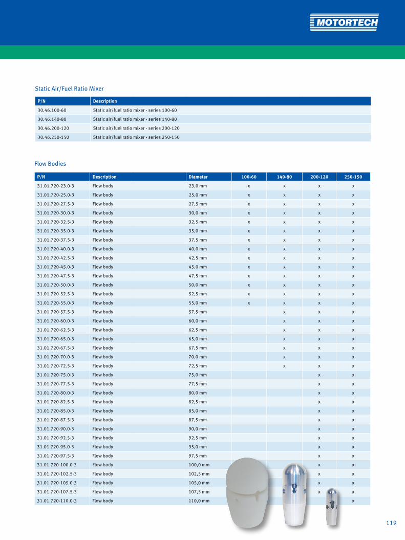
119
Static Air/Fuel Ratio Mixer
P/N Description
30.46.100-60 Static air/fuel ratio mixer - series 100-60
30.46.140-80 Static air/fuel ratio mixer - series 140-80
30.46.200-120 Static air/fuel ratio mixer - series 200-120
30.46.250-150 Static air/fuel ratio mixer - series 250-150
Flow Bodies
P/N Description Diameter 100-60 140-80 200-120 250-150
31.01.720-23.0-3 Flow body 23,0 mm x x x x
31.01.720-25.0-3 Flow body 25,0 mm x x x x
31.01.720-27.5-3 Flow body 27,5 mm x x x x
31.01.720-30.0-3 Flow body 30,0 mm x x x x
31.01.720-32.5-3 Flow body 32,5 mm x x x x
31.01.720-35.0-3 Flow body 35,0 mm x x x x
31.01.720-37.5-3 Flow body 37,5 mm x x x x
31.01.720-40.0-3 Flow body 40,0 mm x x x x
31.01.720-42.5-3 Flow body 42,5 mm x x x x
31.01.720-45.0-3 Flow body 45,0 mm x x x x
31.01.720-47.5-3 Flow body 47,5 mm x x x x
31.01.720-50.0-3 Flow body 50,0 mm x x x x
31.01.720-52.5-3 Flow body 52,5 mm x x x x
31.01.720-55.0-3 Flow body 55,0 mm x x x x
31.01.720-57.5-3 Flow body 57,5 mm x x x
31.01.720-60.0-3 Flow body 60,0 mm x x x
31.01.720-62.5-3 Flow body 62,5 mm x x x
31.01.720-65.0-3 Flow body 65,0 mm x x x
31.01.720-67.5-3 Flow body 67,5 mm x x x
31.01.720-70.0-3 Flow body 70,0 mm x x x
31.01.720-72.5-3 Flow body 72,5 mm x x x
31.01.720-75.0-3 Flow body 75,0 mm x x
31.01.720-77.5-3 Flow body 77,5 mm x x
31.01.720-80.0-3 Flow body 80,0 mm x x
31.01.720-82.5-3 Flow body 82,5 mm x x
31.01.720-85.0-3 Flow body 85,0 mm x x
31.01.720-87.5-3 Flow body 87,5 mm x x
31.01.720-90.0-3 Flow body 90,0 mm x x
31.01.720-92.5-3 Flow body 92,5 mm x x
31.01.720-95.0-3 Flow body 95,0 mm x x
31.01.720-97.5-3 Flow body 97,5 mm x x
31.01.720-100.0-3 Flow body 100,0 mm x x
31.01.720-102.5-3 Flow body 102,5 mm x x
31.01.720-105.0-3 Flow body 105,0 mm x x
31.01.720-107.5-3 Flow body 107,5 mm x x
31.01.720-110.0-3 Flow body 110,0 mm x

120
Outlet Flange Kits
P/N Description 100-60 140-80 200-120 250-150
31.01.764 Outlet flange kit, gas relaxation section for throttle, series 50 x
31.01.765 Outlet flange kit, gas relaxation section for throttle, series 100 x
31.01.766 Outlet flange kit, gas relaxation section for throttle, series 50 x
31.01.768 Outlet flange kit, for MAN® E0834LE302/ E0836LE202 x
31.01.750 Outlet flange kit, for MAN® E2876LE202/ 212/ 302 x
31.01.752 Outlet flange kit, welding neck flange, DN100 x
31.01.753 Outlet flange kit, for MAN® E0836LE202 x
31.01.755 Outlet flange kit, DN65-PN6 x
31.01.756 Outlet flange kit, for MAN® E2842E312 x
31.01.757 Outlet flange kit, for throttle, series 100 x
31.01.762 Outlet flange kit, gas relaxation section for throttle, series 100 x
31.01.763 Outlet flange kit, gas relaxation section for throttle, series 140 x
31.01.773 Outlet flange kit, for LIEBHERR® G934/ G944 x
31.01.781 Outlet flange kit, for LIEBHERR® G946 x
31.01.751 Outlet flange kit, welding neck flange, DN150 x
31.01.754 Outlet flange kit, for MAN® E2842LE312 x
31.01.758 Outlet flange kit, hose connection, DN200 x
31.01.759 Outlet flange kit, for MAN® E2876LE202/ 212/ 302 x
31.01.761 Outlet flange kit, welding neck flange, DN150 - aluminum x
31.01.767 Outlet flange kit, for DEUTZ® TCG2015V6/ V8 x
31.01.772 Outlet flange kit, for SHENGDONG® 600GF1-PS x
31.01.774 Outlet flange kit, for LIEBHERR® G936 x
31.01.775 Outlet flange kit, for LIEBHERR® G9508 x
31.01.776 Outlet flange kit, for LIEBHERR® G9512 x
31.01.777 Outlet flange kit, for LIEBHERR® G946/ DOOSAN® GV158.3013.D x
31.01.778 Outlet flange kit, for LIEBHERR® G9508 x
31.01.779 Outlet flange kit, linkage for 2 static mixers - series 200-1xx x
31.01.780 Outlet flange kit, for MAN® E2848/ 42LE322/ E3268/62LE2xx x
GAS REGULATION

121
Gas Inlet Flanges
P/N Description Thread 100-60 140-80 200-120 250-150
31.01.359-075 Gas inlet flange G 3/4 x
31.01.359-075NPT Gas inlet flange 3/4 NPT x
31.01.359-100 Gas inlet flange G 1 x
31.01.359-100NPT Gas inlet flange 1 NPT x
31.01.359-125 Gas inlet flange G 1 1/4 x
31.01.359-125NPT Gas inlet flange 1 1/4 NPT x
30.30.102 Gas inlet flange G 1 x
30.30.102-NPT Gas inlet flange 1 NPT x
30.30.103 Gas inlet flange G 1 1/4 x
30.30.103-NPT Gas inlet flange 1 1/4 NPT x
30.30.104 Gas inlet flange G 1 1/2 x
30.30.104-NPT Gas inlet flange 1 1/2 NPT x
30.30.106 Gas inlet flange G 1 1/2 x
30.30.106-NPT Gas inlet flange 1 1/2 NPT x
30.30.107 Gas inlet flange G 2 x
30.30.107-NPT Gas inlet flange 2 NPT x
30.30.108 Gas inlet flange G 2 1/2 x
30.30.108-NPT Gas inlet flange 2 1/2 NPT x
30.30.114 Gas inlet flange G 4 x
Main Adjustment Screws
P/N Description Thread 100-60 140-80 200-120 250-150
30.20.002 Main adjustment screw, mechanical G 3/4 x
30.20.003 Main adjustment screw, mechanical G 1 x x
30.20.004 Main adjustment screw, mechanical G 1 1/4 x x
30.20.005 Main adjustment screw, mechanical G 1 1/2 x x
30.20.006 Main adjustment screw, mechanical G 2 x
30.20.007 Main adjustment screw, mechanical G 2 1/2 x

122
Gaskets for Outlet Flange Kits1)
P/N Static Mixer-Sided P/N Engine-Sided Included in P/N
31.01.365 03.90.050 Outlet flange kit, gas relaxation section for throttle, series 50 31.01.764
31.01.365 03.90.100 Outlet flange kit, gas relaxation section for throttle, series 100 31.01.765
31.01.858 03.90.050 Outlet flange kit, gas relaxation section for throttle, series 50 31.01.766
31.01.858 31.01.365 Outlet flange kit, for MAN® E0834LE302/ E0836LE202 31.01.768
31.01.809 31.01.876 Outlet flange kit, for MAN® E2876LE202/ 212/ 302 31.01.750
31.01.809 Outlet flange kit, welding neck flange, DN100 31.01.752
31.01.809 31.01.858 Outlet flange kit, for MAN® E0836LE202 31.01.753
31.01.809 31.01.867 Outlet flange kit, DN65-PN6 31.01.755
31.01.809 31.01.871 Outlet flange kit, for MAN® E2842E312 31.01.756
31.01.809 03.90.100 Outlet flange kit, for throttle, series 100 31.01.757
31.01.809 03.90.100 Outlet flange kit, gas relaxation section for throttle, series 100 31.01.762
31.01.809 03.90.140 Outlet flange kit, gas relaxation section for throttle, series 140 31.01.763
31.01.809 Outlet flange kit, for LIEBHERR® G934/ G944 31.01.773
31.01.809 Outlet flange kit, for LIEBHERR® G946 31.01.781
31.01.828 Outlet flange kit, welding neck flange, DN150 31.01.751
31.01.828 31.01.863 Outlet flange kit, for MAN® E2842LE312 31.01.754
31.01.828 Outlet flange kit, hose connection, DN200 31.01.758
31.01.879 31.01.879 Outlet flange kit, for MAN® E2876LE202/ 212/ 302 31.01.759
31.01.828 Outlet flange kit, welding neck flange, DN150 - aluminum 31.01.761
31.01.828 31.01.886 Outlet flange kit, for DEUTZ® TCG2015V6/ V8 31.01.767
31.01.371/ 31.01.828 31.01.371/ 31.01.372 Outlet flange kit, for SHENGDONG® 600GF1-PS 31.01.772
31.01.828 Outlet flange kit, for LIEBHERR® G936 31.01.774
31.01.828 Outlet flange kit, for LIEBHERR® G9508 31.01.775
31.01.828 Outlet flange kit, for LIEBHERR® G9512 31.01.776
31.01.828 Outlet flange kit, for LIEBHERR® G946/ DOOSAN® GV158.3013.D 31.01.777
31.01.828 Outlet flange kit, for LIEBHERR® G9508 31.01.778
31.01.828 31.01.377 Outlet flange kit, linkage for 2 static mixers - series 200-1xx 31.01.779
31.01.828 31.01.828 Outlet flange kit, for MAN® E2848/ 42LE322/ E3268/62LE2xx 31.01.780
1) Gaskets included in each outlet flange kit.
GAS REGULATION

123
NOTES

124 124
GAS REGULATION
The stepper motor card manufactured by MOTORTECH guarantees the ideal control of the various types of MOTORTECH VariFuel2 Air/Fuel mixers and integrated throttle bodies.
∙ Precise mixer and throttle adjustment due to microstep operation∙ Error data logging∙ LEDs displaying unit status and activity∙ Combination of several units without signal amplifier/splitter∙ Integrated CANopen interface (as of Firmware 1.6)∙ Configuration via MICT software (comes with controller)∙ Plug-in terminals∙ Easy access to connectors and switches∙ Switch board installation on DIN rail
VariStepMOTORTECH STEPPER MOTOR CARD
Technical Data
∙ 18 – 32 VDC power supply
∙ -15 °C up to +55 °C (5°up to 131° F) ambient
temperature
∙ 0-20 mA/ 0-10V analog input and output,
flexible configuration
∙ 5 digital inputs, 5 to 32 V compatible, DC-
isolated
∙ 6 digital outputs, up to 32 V, 500 mA, DC-
isolated
Interfaces
∙ CAN Bus 2.0b interface (as of Firmware 1.6)
∙ USB 1.1 interface
Configuration
∙ Using the graphic user interface MICT
(MOTORTECH Integrated Configuration Tool)
∙ Manual control via push-button
Housing
∙ Protection class IP 20
∙ Dimensions 217 x 128 x 50 mm
VariStep – Stepper Motor Card for VariFuel2 Air/Fuel Ratio Mixer and Integrated Throttle Bodies
P/N Supersedes Description
31.01.955 31.01.950-100/-140/-200 VariStep stepper motor card

125
The EmCon5 is a lean-burn emission controller for gas engine co-generation units. It is designed to control the exhaust gas emission levels based on indirect measurements. Simply three input signals are required for the control purpose: manifold inlet pressure and temperature and engine load. The lambda sensor (oxygen sensor) is not required and a CH4 input signal is optional.Following initial measurements of the engine emission levels and successful analysis, the EmCon5 guarantees optimal ope-ration of the gas engine at the predefined emission limits.All controller parameters are freely programmable. The adjust-ments and modifications are made via the computer-program “WinScope”. It fits perfectly with the VariFuel2.
Features
• Standardized system available
• Operates without oxygen sensor
• Two gas qualities programmable
• Easy to use
• Available with complete sensor harness (optional)
• Data logging
• Flexible control for reliable operation with biogas
MOTORTECH LEAN-BURN EMISSION CONTROLLEREmCon5

126
Gas
Air
Air Filter
VariFuel2
Turbo ChargerMAPMAT
Throttle
Ball Valve Gas Valve
Gas FilterZERO Pressure
Regulator
Alarm/ ShutdownMAT WarningMixer Warning
9-30 VDC Supply
Intercooler
Load
0-2
0 m
A
Mixer Control
Mixer Feedback
CH4
optio
nal
Engine RunGCB ClosedGas Selection
GAS REGULATION

127
3 4 521
EmCon5 Sensor Harness
P/N Figure Description
06.30.045 2 EmCon5 sensor harness including MAT sensor P/N 56.01.004 and MAP sensor P/N 56.02.017
Manifold Absolute Pressure Sensor
P/N Figure Supersedes Description Thread Pressure Range
56.02.017 3 56.02.016 MAP sensor G 1/4 0 - 3,0 bar
Manifold Air Temperature Sensors
P/N Figure Supersedes Description Thread Fitting Length
56.01.004 4 56.01.021 MAT sensor, PT100, two wire G 1/2 50 mm
56.01.011 4 MAT sensor, PT100, two wire G 1/2 75 mm
56.01.017 4 56.01.005 MAT sensor, PT100, two wire G 1/2 100 mm
Load Transducer
P/N Figure Supersedes Description
63.02.013 5 Load transducer 0-5 A --> 0-20 mA/4-20 mA/0-10 V/2-10 V
w
EmCon5 Control unit
P/N Figure Description
63.02.011 1 EmCon5 lean burn emission control unit

128
GAS REGULATION
Throttle Bodies with Integrated Stepper Motor For Naturally Aspirated and Turbocharged Engines ∙ For use with Natural gas, biogas (minor H2S content),
mine gas, etc.• Available as Series 50, 100, 140, 200• Butterfly diameter 42 – 115 mm (1.65 – 4.53 inch)• Rigid design• High resolution stepper motor• Controlled by MOTORTECH VariStep electronic board• Applicable for temperatures up to 257° F/125° C,
high temperature types (-HT) up to 392° F/200° C
C
IDA
D
B
F
E
MOTORTECH INTEGRATED THROTTLE BODYITB

129Conversion: 1 inch = 25,4 mm / 1 foot = 0,3 m
Series 50 (41 – 42 mm)
P/N Description A B C D E F Inner Diameter
30.42.050-42 Integrated throttle body 88 mm 57 mm 245 mm 96 mm 8 mm 56 mm 42 mm
30.42.050-42-HT1) Integrated throttle body 88 mm 57 mm 270 mm 96 mm 8 mm 56 mm 42 mm
Series 100 (48 – 68 mm)
P/N Description A B C D E F Inner Diameter
30.42.100-60 Integrated throttle body 113 mm 75 mm 270 mm 130 mm 11 mm 61 mm 60 mm
30.42.100-60-HT1) Integrated throttle body 113 mm 75 mm 295 mm 130 mm 11 mm 61 mm 60 mm
30.42.100-68 Integrated throttle body 113 mm 75 mm 270 mm 130 mm 11 mm 61 mm 68 mm
30.42.100-68-HT1) Integrated throttle body 113 mm 75 mm 295 mm 130 mm 11 mm 61 mm 68 mm
Series 140 (73 – 85 mm)
P/N Description A B C D E F Inner Diameter
30.42.140-75 Integrated throttle body 150 mm 95 mm 307 mm 166 mm 11 mm 76 mm 75 mm
30.42.140-75-HT1) Integrated throttle body 150 mm 95 mm 332 mm 166 mm 11 mm 76 mm 75 mm
30.42.140-80 Integrated throttle body 150 mm 95 mm 307 mm 166 mm 11 mm 76 mm 80 mm
30.42.140-80-HT1) Integrated throttle body 150 mm 95 mm 332 mm 166 mm 11 mm 76 mm 80 mm
30.42.140-85 Integrated throttle body 150 mm 95 mm 307 mm 166 mm 11 mm 76 mm 85 mm
30.42.140-85-HT1) Integrated throttle body 150 mm 95 mm 332 mm 166 mm 11 mm 76 mm 85 mm
Series 150 (82 – 104 mm)
P/N Description A B C D E F Inner Diameter
30.42.150-100 Integrated throttle body 150 mm 110 mm 310 mm 196 mm 9 mm 86 mm 100 mm
30.42.150-100-HT1) Integrated throttle body 150 mm 110 mm 348 mm 196 mm 9 mm 86 mm 100 mm
Series 200 (98 – 125 mm)
P/N Description A B C D E F Inner Diameter
30.42.200-100 Integrated throttle body 180 mm 126 mm 342 mm 200 mm 11 mm 110 mm 100 mm
30.42.200-100-HT1) Integrated throttle body 180 mm 126 mm 381 mm 200 mm 11 mm 110 mm 100 mm
30.42.200-105 Integrated throttle body 180 mm 126 mm 342 mm 200 mm 11 mm 110 mm 105 mm
30.42.200-105-HT1) Integrated throttle body 180 mm 126 mm 381 mm 200 mm 11 mm 110 mm 105 mm
30.42.200-115 Integrated throttle body 180 mm 126 mm 342 mm 200 mm 11 mm 110 mm 115 mm
30.42.200-115-HT1) Integrated throttle body 180 mm 126 mm 381 mm 200 mm 11 mm 110 mm 115 mm
Stepper Motor Harness
P/N Description
31.01.942 Stepper motor harness, MIL Style 10 pole socket , 90°
VariStep Stepper Motor Card
P/N Description
31.01.955 VariStep stepper motor card
1) For temperatures up to 392° F/200° C.
w

GAS REGULATION
Throttle Bodies For Naturally Aspirated and Turbocharged Engines Various throttles are available. All moving parts are made of stainless steel to survive in the harshest environments including H2S.• Flange gaskets, lever, end stop and idle speed
adjustment included• Stainless steel ball bearings• Other sizes and custom made designs on request.• Applicable for temperatures up to 284° F/140° C,
high temperature types (-HT) up to 392° F/200° C
MOTORTECH THROTTLES/BUTTERFLY VALVESThrottles
D
F
B
ID
E
H
G
A
C
130

131131
Series 50 (41 – 42 mm)
P/N Supersedes Description A B C D E F G H Inner Diameter
30.40.051-42 30.40.050-42 Throttle body 88 mm 57 mm 135 mm 100 mm 10 mm 96 mm 8 mm 40 mm 42 mm
30.40.051-42-HT1) Throttle body 88 mm 57 mm 135 mm 100 mm 10 mm 96 mm 8 mm 40 mm 42 mm
Series 100 (48 – 68 mm)
P/N Supersedes Description A B C D E F G H Inner Diameter
30.40.101-60 30.40.100-60 Throttle body 113 mm 75 mm 160 mm 100 mm 10 mm 130 mm 11 mm 61 mm 60 mm
30.40.101-60-HT1) Throttle body 113 mm 75 mm 160 mm 100 mm 10 mm 130 mm 11 mm 61 mm 60 mm
30.40.101-68 30.40.100-68 Throttle body 113 mm 75 mm 160 mm 100 mm 10 mm 130 mm 11 mm 61 mm 68 mm
30.40.101-68-HT1) Throttle body 113 mm 75 mm 160 mm 100 mm 10 mm 130 mm 11 mm 61 mm 68 mm
Series 140 (73 – 85 mm)
P/N Supersedes Description A B C D E F G H Inner Diameter
30.40.141-75 30.40.140-75 Throttle body 150 mm 95 mm 200 mm 150 mm 12 mm 166 mm 11 mm 76 mm 75 mm
30.40.141-75-HT1) Throttle body 150 mm 95 mm 200 mm 150 mm 12 mm 166 mm 11 mm 76 mm 75 mm
30.40.141-80 30.40.140-80 Throttle body 150 mm 95 mm 200 mm 150 mm 12 mm 166 mm 11 mm 76 mm 80 mm
30.40.141-80-HT1) Throttle body 150 mm 95 mm 200 mm 150 mm 12 mm 166 mm 11 mm 76 mm 80 mm
30.40.141-85 30.40.140-85 Throttle body 150 mm 95 mm 200 mm 150 mm 12 mm 166 mm 11 mm 76 mm 85 mm
30.40.141-85-HT1) Throttle body 150 mm 95 mm 200 mm 150 mm 12 mm 166 mm 11 mm 76 mm 85 mm
Series 150 (82 – 104 mm)
P/N Supersedes Description A B C D E F G H Inner Diameter
30.40.151-100 30.40.150-100 Throttle body 150 mm 110 mm 200 mm 150 mm 12 mm 196 mm 9 mm 80 mm 100 mm
30.40.151-100-HT1) Throttle body 150 mm 110 mm 200 mm 150 mm 12 mm 196 mm 9 mm 80 mm 100 mm
Series 200 (98 – 125 mm)
P/N Supersedes Description A B C D E F G H Inner Diameter
30.40.201-100 30.40.200-100 Throttle body 180 mm 126 mm 260 mm 150 mm 12 mm 200 mm 11 mm 110 mm 100 mm
30.40.201-100-HT1) Throttle body 180 mm 126 mm 260 mm 150 mm 12 mm 200 mm 11 mm 110 mm 100 mm
30.40.201-105 30.40.200-105 Throttle body 180 mm 126 mm 260 mm 150 mm 12 mm 200 mm 11 mm 110 mm 105 mm
30.40.201-105-HT1) Throttle body 180 mm 126 mm 260 mm 150 mm 12 mm 200 mm 11 mm 110 mm 105 mm
30.40.201-115 30.40.200-115 Throttle body 180 mm 126 mm 260 mm 150 mm 12 mm 200 mm 11 mm 110 mm 115 mm
30.40.201-115-HT1) Throttle body 180 mm 126 mm 260 mm 150 mm 12 mm 200 mm 11 mm 110 mm 115 mm
IMPCO® Replacement Series 100/1401)
P/N Supersedes Description Inner Diameter Equivalent to
30.40.101-68AT2-7 Throttle body 68 mm AT2-7
30.40.141-94AT2-9 Throttle body 94 mm AT2-9
1) Common applications e.g. CATERPILLAR® G379 / G3306 / G3406, WAUKESHA® F1197
Series 160 for CATERPILLAR® G3400 and G3500 Series
P/N Supersedes Description Inner Diameter Equivalent to
30.40.161-106 Throttle body 106 mm 7E1585 / 7E1589
w
1) For temperatures up to 392° F/200° C.

132
GAS ENGINE ACCESSORIES
OLC – Oil Level Controller Combustion engines, compressors, turbines, slide bea-rings and gears – they all depend on a reliable supply of lubricating oil. For trouble-free operation, each of those systems, dependent on the design, requires a precisely defined oil level that may only be exceeded or undercut by a narrow margin. Moreover, the lubricating capacity of the oil is depleted after a certain operating time – it has to be changed.
Oil level monitoring, oil refill, and even an automated oil change – in other words, the complete management of the oil cycle – can be realized in a completely reliable manner with MOTORTECH‘s OLC oil level controller.
MOTORTECH OIL LEVEL CONTROLLEROLC
Features
• Housing made of a high-grade, saltwater-resistant aluminum alloy
• Individually and infinitely adjustable float switches with reed contacts
• Potential-free closing or opening switches, no voltage transfer
• One-shot switches with step response and unambiguous switching states
• Contacts do not come into contact with oil, protection class IP 65
• Vibration-proof, no interference caused by worn rods/ valve seats
• 2, 3 or 4 contacts
• Optional analog level indicator 4-20 mA / 0-10 V
• Floats resistant to all oils
• Contact protection thanks to integrated resistor
• Switch point adjustment requires the use of tools
• Fail-safe wires
• Suitable for mineral and synthetic oils
• 2 oil and 2 equalization connectors
• Pipe connections with standard inch threads
• Sight glass made of impact-resistant polycarbonate
• Glass sealed with Perbunan (NBR)
• Interior painted white for optimal recognition of oil level
• Slotted holes allow for height adjustment during installation
• Indication of engine wear based on refill frequency
• Indication of water in lubricating oil is possible
• Optional Ex protection as per ATEX, CSA or UL on request

133
OLC Oil Level Controller with Analog Level Sensor 4–20 mA – Transducer in Metal Housing
P/N Description Float Switch Cable Length Cable Insulation
80.01.214 OLC oil level controller with analog level sensor 4.0 m PVC
80.01.214-1104 OLC oil level controller with analog level sensor MIN 4.0 m PVC
80.01.214-1204 OLC oil level controller with analog level sensor MAX 4.0 m PVC
80.01.214-2104 OLC oil level controller with analog level sensor MIN/MAX 4.0 m PVC
OLC Oil Level Controller with two Float Switches
P/N Description Cable Length Cable Insulation
80.01.210-2001 OLC oil level controller 1.0 m PVC
80.01.210-2004 OLC oil level controller 4.0 m PVC
OLC Oil Level Controller with three Float Switches
P/N Description Cable Length Cable Insulation
80.01.210-3001 OLC oil level controller 1.0 m PVC
80.01.210-3004 OLC oil level controller 4.0 m PVC
OLC Oil Level Controller with four Float Switches
P/N Description Cable Length Cable Insulation
80.01.210-4001 OLC oil level controller 1.0 m PVC
80.01.210-4004 OLC oil level controller 4.0 m PVC
Double Solenoid Valves
P/N Description Coil Voltage Maximum Pressure Cable Length Cable Insulation
81.00.310-01 Double solenoid valve, 2/2 way 230 V / 50 Hz 24 bar 1.0 m PVC
81.00.310-04 Double solenoid valve, 2/2 way 230 V / 50 Hz 24 bar 4.0 m PVC
81.00.311-01 Double solenoid valve, 2/2 way 24 V 16 bar 1.0 m PVC
81.00.311-04 Double solenoid valve, 2/2 way 24 V 16 bar 4.0 m PVC
81.00.312-01 Double solenoid valve, 2/2 way 12 V 16 bar 1.0 m PVC
81.00.312-04 Double solenoid valve, 2/2 way 12 V 16 bar 4.0 m PVC
81.00.313-01 Double solenoid valve, 2/2 way 24 V / 50 Hz 24 bar 1.0 m PVC
81.00.313-04 Double solenoid valve, 2/2 way 24 V / 50 Hz 24 bar 4.0 m PVC
Solenoid Valves
P/N Description Coil Voltage Maximum Pressure Cable Length Cable Insulation
81.00.300-01 Solenoid valve, 2/2 way 230 V / 50 Hz 24 bar 1.0 m PVC
81.00.300-04 Solenoid valve, 2/2 way 230 V / 50 Hz 24 bar 4.0 m PVC
81.00.301-01 Solenoid valve, 2/2 way 24 V 16 bar 1.0 m PVC
81.00.301-04 Solenoid valve, 2/2 way 24 V 16 bar 4.0 m PVC
81.00.302-01 Solenoid valve, 2/2 way 12 V 16 bar 1.0 m PVC
81.00.302-04 Solenoid valve, 2/2 way 12 V 16 bar 4.0 m PVC
81.00.303-01 Solenoid valve, 2/2 way 24 V / 50 Hz 24 bar 1.0 m PVC
81.00.303-04 Solenoid valve, 2/2 way 24 V / 50 Hz 24 bar 4.0 m PVC
Oil Pumps
P/N Description Voltage Connec-ted Load Protection class Max. pump
capacity Max Pressure
81.00.510 Oscillating piston pump 230 V / 50 Hz 30 W IP 66 0.4 l/min. 0.7 bar
81.00.511 Oscillating piston pump 230 V / 50 Hz 60 W IP 65 1.5 l/min. 2.5 bar

134
GAS ENGINE ACCESSORIES
MOTORTECH CUSTOM MADE STAINLESS STEEL FILTERSCoolantFilterStainless Steel Coolant Filters for stationary applicationsThese bypass filters with stainless steel filter elements clean coolant liquids from all deposits. Elements can be washed and do not need to be disposed. Increases water pump life, cylinder head efficiency and equipment availability. Reduces service and maintenance cost.
Features
• Easy to install
• Cleans and maintains coolant system from rust and contaminants
• Increases water pump life
• Reduces coolant deposits and increases cylinder head efficiency and life
• Stainless steel filter elements can be cleaned – NO WASTE
• Visual flow indicator (stationary applications)
• Easy to service – decreases maintenance cost
• Filter micron rating:
standard – 50 micron
optional – 25 micron
• Flow rate up to 30 GPM
Technical Advantage
• Inhibits electro-chemical degradation of engine components. An industrial gas engine has the characteristics of a large battery when coolant is circulated through the engine block. Contami-nants and suspended solids in the coolant act as a conductor, which more readily allows current to flow throughout the engine block, which degrades EPDM, buna, rubber, viton, and soft metal or alloy components / water pump bearings, impellers, etc.
• Cleaned coolant inhibits corrosion on engine com-ponents such as cylinder heads, cylinder liners and seals, water pump impellers and bearings, etc.
• Prevents „FLASH-OFF“ in the cylinder heads when engine has an emergency stop; as the coolant can properly dissipate thermal loads
• Inhibits scale deposits on all coolant passages and interior thermal surfaces of the engine block.

135
Standard (for Temperatures up to 200° F / 95° C)
P/N Description Element Outside Diameter
Element Length
Micron Rating1) Stand Flow
Indicator
25.00.009-50-30 Coolant Filter 5.00 in. 9.00 in. 50 30.00 in. X
25.00.009-50 Coolant Filter 5.00 in. 9.00 in. 50 X
25.00.009-50-B99 Coolant Filter 5.00 in. 9.00 in. 50 X
25.00.018-50-49 Coolant Filter 5.00 in. 18.00 in. 50 49.00 in. X
25.00.018-50 Coolant Filter 5.00 in. 18.00 in. 50 X
1) For 25 micron filter elements please change part number from -50 to -25.
High Temperature (for Temperatures from 200° F / 95° C up to 400° F / 205° C)
P/N Description Element Outside Diameter
Element Length
Micron Rating1) Stand Flow
Indicator
25.00.009-50-30-HT Coolant Filter 5.00 in. 9.00 in. 50 30.00 in. X
25.00.009-50-HT Coolant Filter 5.00 in. 9.00 in. 50 X
25.00.018-50-49-HT Coolant Filter 5.00 in. 18.00 in. 50 49.00 in. X
25.00.018-50-HT Coolant Filter 5.00 in. 18.00 in. 50 X
1) For 25 micron filter elements please change part number from -50 to -25.
Single Elements
P/N Description Element Outside Diameter
Element Length
Micron Rating
25.00.109-25 Coolant Filter Element 5.00 in. 9.00 in. 25
25.00.109-50 Coolant Filter Element 5.00 in. 9.00 in. 50
25.00.118-25 Coolant Filter Element 5.00 in. 18.00 in. 25
25.00.118-50 Coolant Filter Element 5.00 in. 18.00 in. 50
Shipping Cases for Elements
P/N Description Element Length
25.00.209 Shipping Case 9.00 in.
25.00.218 Shipping Case 18.00 in.

136
GAS ENGINE ACCESSORIES
CUSTOM MADE STAINLESS STEEL FILTERSLubeOilFilter
100% Stainless Steel Construction
Stainless steel micronic wire cloth available in micron ratings of 3-400 absolute. Welded serial #, ID tag
304 or 316, 20-gauge stainless steel perforated inner / outer tube 3/16 in. on 1/4 in. centers
High heat resistant adhesive attaches end caps to filter
Seals available in Buna-N, HSN, Teflon and Viton to suit your application
Over 800 different filters – all to your exact specifications.
Features
• Cleanable
• Consistent
• Environmentally friendly
• Reduce hazardous contaminants
• High payback
• Direct replacement
• Greater fluid flow
• Extends maintenance intervals
• Improves performance
• Provides predictive tool
• Reduces inventory
• Extends equipment life
Engine and compressor filters
Stainless steel replacement elements available for:WAUKESHA®
WHITE SUPERIOR®
CATERPILLAR®
INGERSOLL RAND®
COOPER BESSEMER®
AJAX®
All filters are 100% stainless steel constructions. Filters are available in ratings of 3-400 micron absolute. Standard seal buna „N“
- viton, silicone etc. - optional.
Process and hydraulic filters
Stainless steel replacement elements available for:PECO®
PALL®
PEACOCK®
CUNO®
FILTERITE®
NOWATA®
SCHROEDER®
POROUS MEDIA®
FAIREY ARLON®
UCC®
STAUFF®
HERCULES®
GARDNER®
DENVER®
ATLAS®
CORPCO®
BALDWIN®
FACET®
FRAM®
HILCO®
REFILCO®
NUGENT®
VICKERS®
GRESEN®
HYCON®
PARKER®
HYTREX®

137
Element Kits1)
P/N Description Element Outside Diameter
Element Length
Micron Rating
Number of Elements Application Equivalent to
25.00.300-1-CA Lube filter element kit 7.00 in. 30.00 in. 38 1 CATERPILLAR® G3508/12/16
25.00.301-6-CA Lube filter element kit 7.00 in. 13.00 in. 38 6 CATERPILLAR® G3606/08/12/16
25.00.303-1-CA Lube filter element kit 5.00 in. 9.00 in. 38 1 CATERPILLAR® G3406/08
25.00.310-4-WA Lube filter element kit 3.00 in. 15.00 in. 25 4 WAUKESHA® 167602B
25.00.310-7-WA Lube filter element kit 3.00 in. 15.00 in. 25 7 WAUKESHA® 167602B
25.00.310-14WA Lube filter element kit 3.00 in. 15.00 in. 25 14 WAUKESHA® 167602B
25.00.311-4-WA Lube filter element kit 3.00 in. 30.00 in. 25 4 WAUKESHA® 168660B / 489493
25.00.311-7-WA Lube filter element kit 3.00 in. 30.00 in. 25 7 WAUKESHA® 168660B / 489493
25.00.312-1-WA Lube filter element kit 5.00 in. 7.00 in. 75 1 WAUKESHA® 208472B / 489488
25.00.313-1-WA Lube filter element kit 5.00 in. 10.00 in. 75 1 WAUKESHA® 208472C / 489489
25.00.314-10-WA Lube filter element kit 3.00 in. 30.00 in. 25 10 WAUKESHA® 168660H
25.00.320-3-WS Lube filter element kit 4.00 in. 18.00 in. 25 3 WHITE SUPERIOR® 6G/GT/GTL/GTLA-B
25.00.320-4-WS Lube filter element kit 4.00 in. 18.00 in. 25 4 WHITE SUPERIOR® 8G/GT/GTL/ GTLA-B/SGTB
25.00.320-5-WS Lube filter element kit 4.00 in. 18.00 in. 25 5 WHITE SUPERIOR® 12G/GT/GTL/GTLA-B/SGT/SGTA-B
25.00.320-7-WS Lube filter element kit 4.00 in. 18.00 in. 25 7 WHITE SUPERIOR® 16G/GT/GTL/GTLA-B/SGT/SGTA-B
25.00.330-1-AR Lube filter element kit 4.00 in. 9.00 in. 38 1 ARIEL® A-661 / A-06611) All steel lube filter element kits are supplied with a shipping case.
Conversion: 1 inch = 25,4 mm / 1 foot = 0,3 m
Single Elements
P/N Description Element Outside Diameter
Element Length
Micron Rating Element Kit Engine Manufacturer Equivalent to
25.00.300-CA Lube filter element 7.00 in. 30.00 in. 38 25.00.300-1-CA CATERPILLAR® (Triple Length Element)
25.00.301-CA Lube filter element 7.00 in. 13.00 in. 38 25.00.301-6-CA CATERPILLAR® 1W4136
25.00.302-CA Lube filter element 7.00 in. 10.00 in. 38 CATERPILLAR® 1R0726
25.00.303-CA Lube filter element 5.00 in. 9.00 in. 38 25.00.303-1-CA CATERPILLAR® 1R0716 / B99
25.00.310-WA Lube filter element 3.00 in. 15.00 in. 25 25.00.310-4/-7-WA WAUKESHA® 167602B
25.00.311-WA Lube filter element 3.00 in. 30.00 in. 25 25.00.311-4/-7-WA WAUKESHA® 168660B / 489493
25.00.312-WA Lube filter element 5.00 in. 7.00 in. 75 25.00.312-1-WA WAUKESHA® 208472B / 489488
25.00.313-WA Lube filter element 5.00 in. 10.00 in. 75 25.00.313.1-WA WAUKESHA® 208472C / 489489
25.00.314-WA Lube filter element 3.00 in. 30.00 in. 25 25.00.314-1-WA WAUKESHA® 168660H
25.00.315-WA Lube filter element 5.00 in. 17.00 in. 25 WAUKESHA® 489491 / 305351E
25.00.316-WA Lube filter element 4.00 in. 8.00 in. 25 WAUKESHA® 489495 / 304126
25.00.317-WA Lube filter element 5.00 in. 12.00 in. 25 WAUKESHA® 489490 / 305315C
25.00.318-WA Lube filter element 4.00 in. 16.00 in. 25 WAUKESHA® 172607 / 489522
25.00.320-WS Lube filter element 4.00 in. 18.00 in. 25 25.00.320-3/-4/-5/-7 WHITE SUPERIOR® 758-133
25.00.330-AR Lube filter element 4.00 in. 9.00 in. 38 25.00.330-1-AR ARIEL® A-661 / A-0661
25.00.335-EMD Lube filter element 6.00 in. 30.00 in. 38 EMD® Locomotive Engines 8345482
AccessoriesP/N Description Element Kit
25.00.222 Pressure gauge, liquid filled
25.00.226 Grommet seal 25.00.311-WA
25.00.228 Grommet seal, Viton 25.00.300-CA / 25.00.302-CA
25.00.229 Seal kit 25.00.330-1-AR
25.00.231 Grommet seal, Viton 25.00.310-WA / 25.00.311-WA / 25.00.314-WA

138
GAS ENGINE ACCESSORIES
CLEANING STATIONSUltraSonicUltrasonic Cleaning Station• 2,000 Watts of ultrasonic cleaning power• All new, versatile size to meet a variety of parts
cleaning needs• Environmentally safe aqueous cleaning• Easy-to-operate controls for time, temperature and
cleaning cycle automation• Stainless steel tank construction• Dual filter system• Oil removing surface sparger• Optional on-board task light• Heavy-duty locking casters• High velocity ultrasonics, metallurgically attached
transducers• Ultrasonic frequency sweep to enhance cleaning
performance
UltraSonic Cleaning Station
P/N Description
25.00.001-1101) Complete ultrasonic cleaning station, 110V
Consisting of:• Ultrasonic cleaner • Soak tank • Backwash cabinet • Drying cabinet
Included Accessories:• 13 Watt high intensity inspection light• Roll polytubing• Bag sealer• Soak solution, two barrels• Detergent for ultrasonic, two 20 liter pails• Syphon pump for transfer of soak solution• Cleaning video and cleaning procedures• Layout drawing for setting up station• Cleaning detergent for two years
25.00.001-2201) Complete ultrasonic cleaning station, 220 V
Consisting of:• Ultrasonic cleaner • Soak tank • Backwash cabinet • Drying cabinet
Included Accessories:• 13 Watt high intensity inspection light• Roll polytubing• Bag sealer• Soak solution, two barrels• Detergent for ultrasonic, two 20 liter pails• Syphon pump for transfer of soak solution• Cleaning video and cleaning procedures• Layout drawing for setting up station• Cleaning detergent for two years
1) Does not include high pressure washer. Customer preference; 2000 PSI required

139
Soak Tank• Durable powder coated finish• Inside tank dimensions
48 in. x 20 in. x 16 in.• 1,500 Watt screw in heat element
with built in thermostat• 110 Volt power requirements• Castor wheels for easy movement
of unit• Hinged lid• Recirculation pump with 30 minute timer• Optional heated tank
Backwash Cabinet• Powder coated finish• Slotted subfloor parts rack• Water backsplash curtain• Adjustable parts rack• Solids sediment waste water
tank-3 stage• High pressure washer not included
Drying Cabinet• 4,800 Watt – 16000 BTU heating
unit 210 V• Durable powder coated finish• Inside cabinet dimensions
48 in. x 30 in. x 24 in.• 30 minute timer• Hinged door with latch closures
UltraSonic Cleaning Station – Console Style Unit• Inside tank dimensions
(40 in. x 12 in. x 40 in.)• Electric heater, thermostatically
controlled, 4,000 watts• Ultrasonics - 40 KHz, 3,000 watts
with pulse and sweep• Transducers mounted on one side
wall of tank• Mechanical timer (1 - 30 minutes)• Stainless steel lift cover• Power requirements 240 v, 10,
50/60 Hz, 8KVA
Cleaning Vessel• Filtration of the cleaning fluid to ena-
ble maximum cleaning effeciency and extend cleaning solution life
• Pump is 110 V• Filter unit consists of a stainless steel
P2 vessel with a 1/2 HP hi-tempera-ture pump, discharge and suction hose
UltraSonic Cleaning Station– Cabinet Model• Inside tank dimensions
(48 in. x 16 in. x 16 in.)• 25 KHz• Variable power controls• Built-in heater• “Neptune“ Generator with pulse
and sweep• All stainless 316L cabinet construction• Stainless lift off cover• Heavy duty castors• Recessed controls• Recessed tank drain• Available in 110 or 220 volt• 2 year warranty on all components
Further UltraSonic Cleaning Models and Accessories are availaible on request.

Distributed by:
P/N 01.00.001-EN | MOTORTECH PRODUCT GUIDEREV. 06/2015
YOUR WAY TO MOTORTECHMOTORTECH GmbHHogrevestr. 21-2329223 CellePhone: +49 5141 93 99 0Fax: +49 5141 93 99 [email protected]
MOTORTECH Americas, LLC1400 Dealers Avenue, Suite ANew Orleans, LA 70123Phone: +1 504 355 4212Fax: +1 504 355 4217 [email protected]