mountain plains learning experience guide: drafting. course
TRANSCRIPT

DOCUMENT RESUME
ED 197 155 CE 027 785
AUTHOR Wetterling, C.: Wheatley, J.TITLE Mountain Plains Learning Experience Guide: Drafting.
Course: Basic Drawing. Revised Edition.INSTITUTION Mountain-Plains Education and Economic Development
Program, Inc., Glasgow AFB, Mont.SPONS AGENCY Office of Vocational and Adult Education (ED) ,
Washington, D.C.BUREAU NO 49^MH90008PUB DATE Aug 79CONTRACT 300-79-0153NOTE 47O p.: For related documents, see CE 027 766 and CE
027 786.
EDPS PRICE MF01/Pc19 Plus Postage.DESCRIPTORS Adult Education: Disadvantaged: Drafters; *Drafting:
Family Programs: Graphic Arts: *IndividualizedInstruction: Industrial Arts: InstructionalMaterials: Learning Activities: Learning Modules:Orthographic Prolection: Postsecondary Education:*Vocational Education
IDENTIFIERS Mountain Plains Program
ABSTPArTOne of two individualized courses included in a
drafting curriculum, this course is designed to develop thefundamental skills of drafting using mechanical instruments. Thecourse is comprised of thirteen units: (1) Mechanical Drawing, (2)Lettering, (3) Geometric Construction, (4) Shape Description, (5)
Multiview Prolection and Drawing Reproduction, (6) Dimensioning, (7)
Section Views, (B) Auxiliary Views, (9) Templates, (10) PictorialDrawings, (11) Mapping, (12) Intersections and Developments, and (13)Working Drawings. Each unit begins with a unit Learning ExperienceGuide that gives directions for unit completion. The remainder ofeach unit consists of Learning Activity Packages (LAP) that providespecific information for completion of a learning activity. Each LAPis comprised of the following parts: objective, evaluation procedure,resources, procedure, supplemental sheets, study guide, and a LAPtest with answers. The course is preceded by a pretest which isdesigned to direct the student to units and performance activities.(LRA)
***********************************************************************Reproductions supplied by EDRS are the best that can be made
from the original document.***********************************************************************

L(
v-4
Cr1/4
1-4
LAJ MOUNTAIN PLAINS LEARNING EXPERIENCE GUIDE:
Drafting
Course; Basic Drawing
2
U S DEPARTMENT OF HEALTH,EDUCATION &WELFARENATIONAL INSTITUTE OF
EDUCATION
THIS DOCUMENT HAS BEEN REPRO-DUCED EXACTLY AS RECEIVED FROMTHE PERSON OR ORGANIZATION ORIGIN-ATING IT POINTS OF VIEW OR OPINIONSSTATED DO NOT NECESSARILY .REPRE-SENT OFFICIAL NATIONAL INSTITUTE OFEDUCATION POSITION OR POLICY

Pregra
79 01 00 00.A2-1File Code: '
Date Published'10-7-77
Revised: 8-14-79
ft® EzILDGA@Gocc4 @ffldd®COURSE: BASIC DRAWING
DESCRIPTION:
Basic Drawing is a course designed to develop the fundamental skills of drafting usingmechanical instruments. The course includes lettering, sketching, instrument useage, geo-metric construction, dimensioning, and multi-view projection. Students will prepare draw-ings according ASNI specificat4r-ns and develop skills in accuracy, line conventions, neat-ness and speed.
RATIONALE:
Many problems which exist in the world today are caused by the fact that people do notunderstand each other. There are many different languages, dialects, and interpretationsof words which can lead to poor communication and misunderstanding. This causes a breakdownin the exchange of techrical inforr.,tion.
There is one universal language, ho2ver, which is understood by all men. It is the languageof pictures or otherwise known as the "Graphic" language. There am two types of drawingswhich man has adopted, to serve his purposes: 1) Artistic, and 2) Technical. In thiscourse, we will only deal with the latter. Technical drawings are used in all industrialrelated occupations and workers, called draftsmen, must possess certain skills to keep thelanguage of drawing universal. W will study those basic techniques.
PREREQUISITES:
Prescribed entry levels in Math and Communication Skills.
OBJECTIVES:
The student will develop skills in tool useage lettering, geometric construction, shape de-scription, (orthographic projection) orthographic end other forms of projection, dimension-ing, intersections, developh,2nts, mapping and working drawings.
RESOURCES:
*Start with the Printed Materials on Resource list.
GENERAL INSTRUCTIONS;:
This course has thirteen units. Each unit has a Unit Learnirg Experience Guide (LEG) thatgives directions for unit completion. Each unit consists of Learning Activity Packages (LAPs)that provide specific information for completion of a learning activity. Pretesting resultsdirect the student to units and performance activities.
Principal Author(s): C. Wetterl ing, J. Wheatley
9
Family Training CC r be.
Page 2 79.01.00.00:A2-1
GENERAL INSTRUCTIONS (continued):
The general procedure for this course is as follows:
1. Read the assigned Unit LEG for this course.2. Begin and complete the first assigned LAP as explained in'the Unit LEG "General In-
structions".3. Proceed to, and complete, the remaining LAPs in the unit.:4. Take the unit tests as described in the Unit LEG "Evaluation Procedures."5. Proceed to the next assigned unit in this course.6. Follow steps 1 through 4 for all required units for zhis course.7. Take the course post test as described in the "Evaluation-Procedure."
*NOTE: As a draftsperson you will be expected to work independently- -the moreindependent you are, the better. Therefore, in this course, you willbe expected to work independently, unless directed to do otherwise.In most LAPs you will be directed to specific reference books. Youare expected to read and find out as much as possible from these andother available texts before asking questions of your instructor.The resources may or may not be available or may not give you thebest explanation. When this occurs check the other.available resources.
UNIT TITLES:
.01 Mechanical Drawing
.02 Lettering
.U3 Geometric Construction
.04 Shape Description
. 05 Multiview Projection and Drawing Reproduction
.06 Dimensioning
.07 Section Views
.09 Auxiliary Views
.10 Templates
.11 Pictorial Drawings
.12 Mapping
.13 Intersections and Developments
. 14 Working Drawings
EVALUATION PROCEDML:
Course evaluation is by pre and post testing using a multiple-choice type of test, andthru performance testing.
A course pretest is used to determine which units, if any, the student may be able tovalidate. The student is considered validated for a particular unit if 4 out of 5 itemsare correctly answered for each LAP part on the course pretests and if the student alsosatisfactorily completes the unit performance test. Unit performance tests validationprocedures are given in the "Evaluation Procedure" section of the Unit Learning ExperienceGuide (LEG).
A course post test will also be taken by the student to determine any changes resultingfrom taking all or part of the course.
Page 3 79.01.00.00:A2-1
Printed Materials
1. Basic Technical Drawing. Spencer and Dygdon, Macmillan Company, New York, 1968.2. Catalog collection (Building Trades supplies).3. Drafting Technology. Rotmans and Horton, Delmar Publishers, 1967.4. Engineering Drawing and Graphic Technology. Eleventh Edition, French and Vierck,
McGraw-Hill Book Company, 1973.5. Mechanical Drawing. French any Svenson, Webster Division, McGraw-Hill Book Company, 1968.6. Technical Drawing. Sixth Edition, Giesecke, Mitchell, Spencer and Hill, Macmillan Com-
pany, 1974.7. Technical Drawing Problems. Series 1, Giesecke, Spencer, Mitchell and Hill, Macmillan
Company, 1967.8. Assorted references as required by individual need.
Audio/Visuals
1. Drafting Series. (Set of 5 filmstrips and audio/cassette tapes), Doubleday Media.2. Video cassettes (coded to each unit) -- FTC produced,
Equipment
1. Basic drafting tools: adapter, compassboard, draftingbrush, draftingdrawing seteraser, electricerasing shieldFrench curveholder, leadholder, pan (Leroy)knife, X-actolead pointerlettering guide, Ames or equivalentlettering instrument, mechanical (Leroy or equivalent)pens, Leroy (sizes as required)protractorscale, architectscale, engineerscissorsscriber, Leroytemplates, Leroy (W120, 140, and 175)templates (assorted to need)triangles (30° x 60° and 45°)T-square
2. Diazo developer and printer.3. Light box (minimum 24" x 36").4. Cutter, paper (24" or larger).5. Drafting furniture: stool , drafting
table, drafting (with T-square, parallel rule and/or drafting machine).light, drafting
6. Player, audio/cassette.7. Projector, filmstrip.8. Transfer materials and tapes.9. Sony video cassette player/monitor.

FamilyEthication
File Code: 79.01.00.00 C2-0
Date Published: ___/6 17/74
Revised: 11/26/79
COURSE PRE/POST TEST: BASIC DRAWING
79.01.01.01
1. Hard leads are used:
a. for general purpoF- rk in mechanical drawing.b. when extreme accur s required and for basic construction lines.
c. for art work but nu or mechanical drawing.
d. only on hard paper.
2. Medium leads are:
a. used only on medium paper.b. used when extreme accuracy is required and for basic construction lines.
c. the standard leads for general purpose work in mechanical drawing.
d. used for art work.
3. Object lines (visible lines) are:
a. lighter and thinner than construction lines.b. made with a 6-H lead and are the same weight as center lines.c.. heavier than center lines or extension lines.d. made with a soft lead like 2-B or 2-F.
4. Wherever possible, pencil lines should be:
a. wider than ink lines.b. thinner than ink lines.c. wider or thinner than ink lines.d. the same width as ink lines.
5. In our course, it is suggested you use which lead for construction lines:
a. 2-Hb. H
c. 4-HH. 6-H
79.01.01.02
6. When mounting paper to the drawing board, the top edge of the paper is lined
up with:
a. tape and tacks.b. a large triangle.c. the compass geometric method.d. the top (working) edge of the T-square.
6
batik Trainim Center Ince

Page 2
79.01.01.02 (continued)
7. The paper is held to the board with:
a. nails or brads.b. glue.c. drafting paste.d. staples, thumb tacks, or tape.
79.01.00.nn C2-0
8. Paper is attached to the board by right handers in which sequence?
a. Lower right, upper right, lower left, upper left.b. Lower left, upper left, lower right, upper right.c. Lower right, lower left, upper right, upper ',eft.d. Upper left, lower right, upper right, lower left.
9. If the drawing paper is not cut straight, it should be:
a. aligned by using the straightest edge possible.b. thrown away.c. used for scratch 1.aper.d. returned to the storage cabinet.
10. Drawing paper should be placed:
a. up-side down.b. on top of the T-square.c. away from the working edge and close to the bottom of the board.d. close to the working edge and away from the bottom of the board.
79.01.01.03
11. To draw a horizontal line, the T-square should be held:
a. at the end of the blade.b. firmly and tight against the paper.c. with the compass or dividers.d. loosely and away from the paper.
12. When drawing horizontal lines, the lead holder should be held:
a. 45 degrees to the paper in the direction of the line.b. 60 degrees to the paper in the direction of the line.c. vertical to the paper in the direction of the line.d. 30 degrees to the paper in the direction of the line.
1. A horizontal line is drawn:
a. from left to right if you are right handed.L. from right to left if you are right handed.c. from left to right if you are left handed.d. from left to right or right to left.

Page 3 71).01.00.00. C2-0
79.01.01.03 (continued)
14. When drawing horizontal lines, the lead holder should be:
a. turned from side to side.b. held firmly and not rotated.
c. rotated as rapidly as possible.d. rotated slowly to wear the point evenly.
15. When drawing horizontal lines, the'head of the T-square;is held:
a. on top of the board.b. loosely.C. firmly against the working edge of the board.
d. on the bottom of the board.
79.01.01.04
16. When drawing vertical lines, the lead holder should be held:
a. 45 degrees to the paper in the direction of the line.
b. 60 degrees to the paper in the direction of the ling.
c. 30 degrees to the paper in the direction of thed. vertical to the paper in the direction of the line.
17. When drawing vertical lines, the lead holder should be:,
a. held firmly and not rotated.
b. turned from side to side.c. rotated as rapidly as possible.d. rotated slowly to even wear on the lead.
18. To draw a vertical line, you would use:
a. the T-square with the head held against the top of !the board.
b. the architects scale.c. either you 30/60 triangle or your 45° triangle.
d. your d-.-,wing set.
19. When drawing vertical lines and great accuracy is required:
a. toe the lead holder in against the T-square.
b. toe the lead holder in against the triangle.
c. use a harder drawing board.d. don't draw the line.
20. When drawing vertical lines and the edge of the triangle is too sharp:
a. throw it away.b. sand the edge lightly with #00 sand paper.
c. sharpen the lead.d. don't draw the line.

Page 4
79.01.01.05
21. In Figure # 1, distance A is:
a. 1.65 inches.b. PI inches.c. 2.5 inches.d. 3 1/16 inches.
22. In Figure # 2, distauce 0 to B is:
a. 1 inch.b. 100 inches.c. 100 feet.d. 10 feet.
23. In Figure # 2, the 10 means:
a. 10 graduations to the inch.b. 10 inches to the graduation.c. a 10 to 1 scale.d. the scale is 10 inches long.
Iq.01.00.00. C?-0
FIGURE #1
24. In Figure # 2, the distance form 0 to 2 is:
a. 2 inches.b. 20 meters.c. 200 feet.d. 200 units.
25. In Figure # 3, distance A represents:
FIGURE 42
FIGURE #3
a.
b.
c.
d.
7 feet..7 inch.7 meters..7 feet
1;Iii10 io
1 1 i 1 11 1 1 i
17
99
-_scale 1"=1'----

Page 5 79.01.00.00. C2-0
79.01.01.06
FIGURE #4
a.
26. When centering a two view drawing:
a. distance A can be any length you decide.b. distance A never equals distance B.c. distance A always equals 2 inches.d. distance A always equals distance B.
27. The formula i'or vertical spacing is: (use Figure 4)
a. A plus B divided by 2.b. A plus B divided by 3.c. H minus (J plus G) divided by 2.d. H minus (J plus G) divided by 3.
28. The formula for horizontal spacing in a 2 view drawing is: (use Fioure #4)
a. I minus F divided by 2.b. I minus F divided by 3.c. C plus D plus E divided by 2.d. C plus 0 plus E divided by '3.

Page 6 79.01.00.00. C2-0
79.01.01.06 (continued)
29. When spacing a two-view drawing, the width of the top and front views is:
a. different by 1 inch.h. the same.
different by 2 inches.d. different by 3 inches.
30. Using Figure #4, what dimension represents object height?
a. H
b. J
c. D
d. G
79.01.01.07 FIGURE #5
31. When centering a 3-view drawing (as in Figure #5):
a. distances A and B are always equal.b. distances D and F are always equal.c. distances D and C are always equal.d. distances H and G are always equal.

Page 7 79.01.00.00. C2-0
79.01.01.07 (continued)
32. The formula for horizontal spacing is: (use Figure #5)
..a. A + B + C t by 3.b. I - (2 X K) t by 2.c. (A + 8 + C) t by 2.
d. (K + H) + by 2.
33. The first step in drawing a 3-view drawing to:
a. draw circles and arcs.b. draw horizontal lines.c. draw vertical lines.d. determine the spacing.
34. The formula for vertical spacing is: (use Figure #5)
a. J (H + G) + by 2.
b . J- (H X 2) t by 3.c. J - (H + E + G) t by 2.d. (D + E + F) t by 3.
35. What dimension on Figure #5, represents object width:
a. H
b. K
c. G
d. J
79.01.01.08
36. When drawing ink lines, the ruling pen should be:
a. at an angle of 45° to the paper in the direction of the line.
b. at an angle of 60° to the paper in the direction of the line.
c. at an angle of 90° to the paper in the direction of the line.
d. at airy Pngle that is comfortable.
37. When drawing ink lines, the automatic reservoir pen should be:
a. at an angle of 60° to the paper in the direction of the line.
b. at an angle of 90° to the paper in the direction of the line.
c. at an angle of 45° to the paper in the direction of the line.
d. at any angle that is comfortable.
38. Thicker ink lines with the ruling pen are caused
a. fresh ink and a clean pen.b. rapid movement of pen.c. sharp nibs.d. all the above.
1.2

Page 8 79.01.00.00. C2-0
79.01.01.08 (continued)
39. When inking or tracing a pencil line, the ink line should be:
a. above the pencil line.b. centered over the pencil line.c. below the pencil line.d. longer than the pencil line.
40. Lettering, straight lines, curves, and arcs can be done with:
a. the ruling pen, LeRoy pen, and lead holder.b. lead holder, ruling pen, LeRoy pen, and pencil.c. ruling pen and LeRoy pen.d. LeRoy pen and lead holder.
79.01.01.09
41. In Figure #6, B shows:
a. a visible line covering a center line.b. a visible line behind a center line.c. a visible line behind a hidden line.d. a visible line covering a hidden line.
OSA
42. In Figure #7, C shows:
a. a visible line covering a hidden line.b. a hidden line covering a center line.c. a hidden line covering a visible line.d. a visible line covering a center line.
43. In Figure #7, A is a:
a. center line.b. hidden line.c. visible line.d. construction line.
FIGURE 47

Page 9
79.01.01.09 (continued)
44. In Figure #7, D is a:
a. visible line.b. center line.c. hi dden line.d. construction line.
45. The correct order of line precedence is:
a. hidden, center, and visible.b. center, visible, and hidden.c. visible, center, and hidden.d. visible, hidden and center.
79.01.01.10
46. Objectives in drafting are:
a. accuracy, speed, legibility, and neatness.b. equipment, instruments, books, and pencils.c. reading, slow drawing, ink and test books.d. neat drawings, slow work and no accuracy.
47. A pencil drawing, not for reproduction, is made on:
a. polyester film.b. tracing cloth.c. tracing paper.d. drawing or detail paper.
79.01.00.00 C2-0
48. To draw mechanical curves other than circles or circular arcs use a:
a. compass.b. electric eraser.c. drafting machine.d. french e .
49. To save time when drawing syMbol s and repetitive features, use:
a. templates.b. compasses.c. T-square and triangle.d. a drafting machine.
50. To make accurate measurements without damaging the scale:
a. take measurements directly off the scale with dividers or compass.b. place the scale on the drawing and make short dashes at right
angles to the scale.c. use a ruler.d. set off distances individually by moving the scat P to a new position each time.
Page 10 79.01.00.00. C2-0
79.01.02.01
51. The U.S. Standard Style of Lettering is most often used on:
a. architectural drawings.b. machine drawings.c. mapping drawings.d. all of the above.
52. The most common letter height used on drawings is:
a. 1/2"b. 1/4"
c. 1/8"d. 1/16"
53. The height relationship of lower case letters to upper case letters inU.S. Standard is:
a. 1/2 or 2/3 c. 1/2 or 3/4b. 3/4 or 3/5 d. 3/5 or 2/3
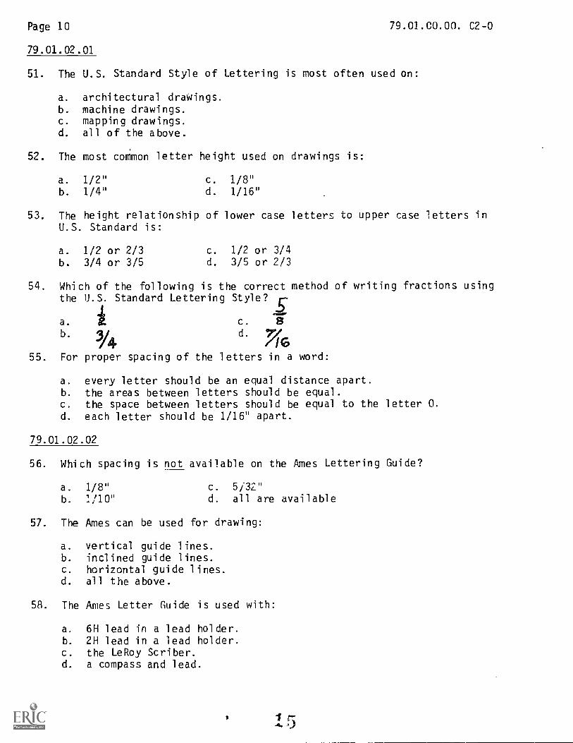
54. Which of the following is the correct method of writing fractions usingthe U.S. Standard Lettering Style?
a. c.
b. .14 d.
/1655. For proper spacing of the letters in a word:
a. every letter should be an equal distance apart.b. the areas between letters should be equal.c. the space between letters should be equal to the letter 0.d. each letter should be 1/16" apart.
79.01.02.02
56. Which spacing is not available on the Ames Lettering Guide?
a. 1/8"
b. 1/10"
c. 5/32"d. all are available
57. The Ames can be used for drawing:
a. vertical guide lines.b. inclined guide lines.c. horizontal guide lines.d. all the above.
58. The Ames Letter Guide is used with:
a. 6H lead in a lead holder.b. 2H lead in a lead holder.c. the LeRoy Scriber.d. a compass and lead.

Page 11 79.01.00.00. C2-0
79.01.02.02 (continued)
59. The numbers on the bottom of the disc in the Ames instrument indicate:
a. the number of letters to the inch.b. the heights of letters in thirty-seconds of an inch.c. the angle to use for slant lettering.d. the fractions that can be drawn.
60. The Ames lettering instrument is used to:
a. draw capital letters.b. draw small letters.c. draw guile lines.d. draw numbers.
79.01.02.03
61. The numbers on the LeRoy templates (80, 100, 120, etc.) indicate:
a. the letter height in thousandths of an inch.b. the number of letters to the inch.c. the recommended pen size.d. the letter height in thirty-seconds of an inch.
62. The numbers on the LeRoy template (00, 0, 1, 2, etc.) indicate:
a. the number of letters to the inch.b. the recommended pen size.c. the letter height in thousandths of an inch.d. the letter height in thirty-seconds of an inch.
63. When using the LeRoy, the template is placed:
a. along a french curve.b. along a straightedge.c. on top of the scriber.d. on top 0° t;ie varigraph.
64. The LeRoy Scriber can be adjusted to:
a. scribe edge letters.b. draw script letters.c. draw vertical letters only.d. draw inclined letters.
65. Which template will make the largest letters?
a. 61-1250-24PC c. 61-300-350CLb. 61-300-290CL d. 61-300-80CL
Page 12
79.01.03.01
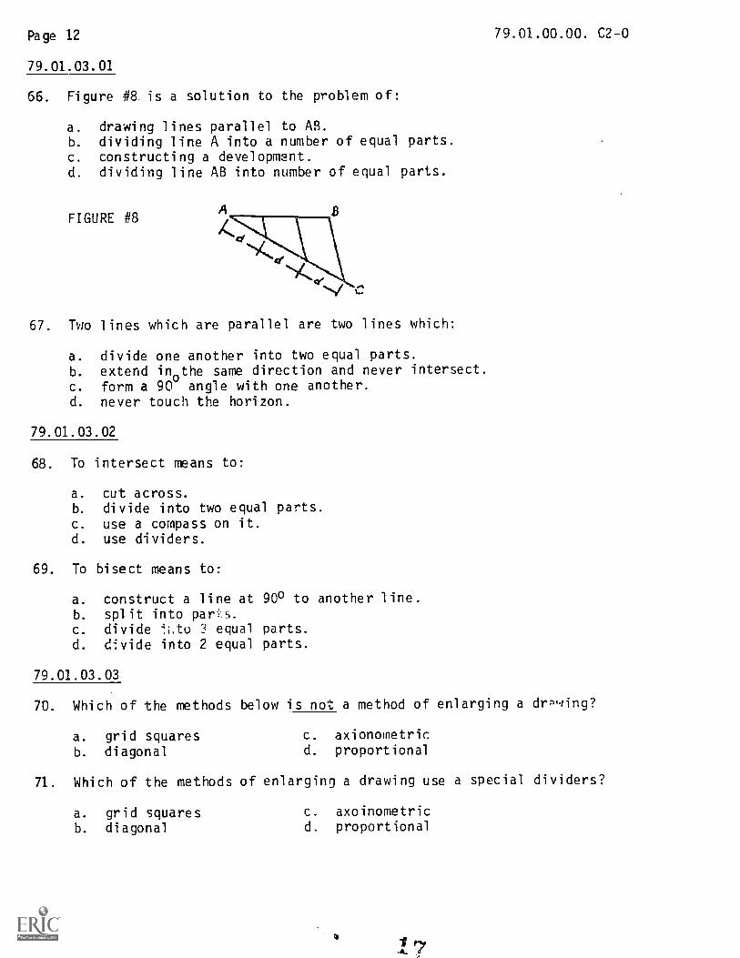
66. Figure #8 is a solution to the problem of:
a. drawing lines parallel to AB.b. dividing line A into a number of equal parts.c. constructing a development.d. dividing line AB into number of equal parts.
FIGURE #8
67. Two lines which are parallel are two lines which:
a. divide one another into two equal parts.b. extend in
othe same direction and never intersect.
c. form a 90 angle with one another.d. never touch the horizon.
79.01.03.02
68. To intersect means to:
a. cut across.b. divide into two equal parts.c. use a compass on it.d. use dividers.
69. To bisect means to:
a. construct a line at 900 to another line.b. split into paris.c. divide 4.i,to 3 equal parts.d. divide into 2 equal parts.
79.01.00.00. C2-0
79.01.03.03
70. Which of the methods below is not a method of enlarging a drn,qing?
a. grid squares c. axionometric
b. diagonal d. proportional
71. Which of the methods of enlarging a drawing use a special dividers?
a. grid squares C. axoinometricb. diagonal d. proportional
Page 13 79.01.00.00. C2-0
79.01.03.04
72. The interior angles of any triangle total up to:
a. more than 0 degrees but less than 90 degrees.b. 90 degrees.c. 180 degrees.d. more than 90 degrees but less than 180 degrees.
73. An example of a polygon is:
a.
b. 0c'
d. I
79.01.03.05
74. A triangle with two sides equal and two angles equal is:
a. right triangle. c. obtuse.b. scalene. d. isosceles.
75. A triangle with no sides or angles equal is:
a. isosceles. c. equilateral.b. obtuse. d. scalene.
79.01.03.06
76. The side of a right triangle that is opposite the right angle is:
a. the secant. c. the hypotenuse.b. the chord. d. the isosceles.
77. If you bisect the angles of a triangle, the bisectors will
a. be concentric.b. be perpendicular to each other.c. meet at one point.d. pass through the center of the opposite side.
Page 14
79.01.03.07
78. An ecwilateral triangle has:
a. a 90 degree angle.b. three sides unequal.c. three sides equal.d. at least one 75 degree angle.
79.01.00.00. C2-0
79. An equilateral triangle contains at least one angle of:
a. 60°b. 30°
79.01.03.08
80. The diagonal of a square:
c. 45°d. 90°
a. is twice the length of a side.b. bisects a corner angle of the square.
d. is perpendicular to a corner angle.
d. biseGts a side of the square.
81. The sum of the interior angles of a square is:
a. 90°b. 180°c. 360°d. dependent on the length of the sides.
79.01.03.09
82. When a square is inscribed in a circle, the diagonal of the square:
a. bisects the sides of the square.
b. is the diameter of the circle.c. is the radius the circle.
d. is eval to the perimeter the circle.
83. When a square is inscribed in a circle, the center point of the circle:
a. is on a corner of the square.b. lies on a side of the square.c. is closer to the angles of the square than the sides.
d. is at the intersection point of the diagonals.

Page 15
79.01.03.10
84. To circulscribe a square on a circle means:
a. to place the circle outside the square.b. to place the square inside the circle.c. to place the square outside the circle.d. to place the corners of the square on the circle.
85. When a square is circumscribed on a circle:
79.01.00.00. C2-0
a. the length of a side is the diameter of the circle.h. the length of a side is the radius of the circle.c. the length of the diagonal is the diameter of the circle.d. the length of the diagonal is the radius of the circle.
79.01.03.11
86. Figure #9, shown below is:
a. an octagon.b. a pentagon.
c. a decagon.d. a hexagon.
87. The interior angle A shown in Figure #9 is:
a. 72 degrees.b. a right angle.c. 108 degrees.d. not equal to angle B.
FIGURE #9
79.01.03.12/.13
88. The 4nterior angle of a hexagon is:
a. 60°b. 120c. 30'd. the same as a square.
89. The construction shown in Figure #10 below is preliminary to the completion of:
a. a pentagon.b. a nonagon.c. a octagon.d. a hvxagon.
FIGURE #10

Page 16 79.01.00.00. C2-0
79.01.03.12/13 (continued)
90. In all hexagons, the distance from the center point to a vertex is:
a. equal to the diameter of a circle inscribed within the hexagon.
b. equal to the length of a bisector.c. shorter than the length' of a side of the hexagon.
d. equal to the length of a side of the hexagon.
79.01.03.14
91. An octagon has how many vertexes?
a. 4 c. 8
b. 6 d. 10
92. What is the sum of the interior angles of an octagon?
a. 135°b. 360°
C. 720°d. 1080°
79.01.03.15
93. A straight line which connects 2 points on the perimeter of a circle or
arc and does not pass through the center is a:
a. chord. c. radius.
b. diameter. d. tangent.
94. Two circles or arcs which have a common center are said to be:
a. tangent.b. concentric.
c. eccentric.d. ellipsoidal.
79.01.03.16
95. A method of finding the center of an arc or circle is to:
a. construct a line tangent to the circle or arc.
b. rectify the arc or circle.c. intersect the arc or circle.d. bisect any 2 chords on the arc or circle.
79.01.03.17
96. A line that is tangent to a circle:
a. is perpendicular to the circle's radius at the tangent point.
b. is parallel to the circle's diameter at the tangent point.
c. touches the circle in 2 places.d. passes through the center of the circle
. 2

Page 17 79.01.00.00. C2-0
79.01.03.18
97. An arc tangent to a straight line:
a. touches the line at one point only.b. passes through the line at the point of tangency.c. bisects the line.d. uses the line as a diameter.
79.01.03.19
98. To locate the center of a circle tangent to two intersecting straight lines,you would:
a. bisect each line.b. construct lines perpendicular to the circlec. construct lines parallel to the given lines and the radius of the
circle away.d. bisect the angle between the lines.
79.01.03.20
99. To find the point of tangency of two tangent circles, draw:
a. a straight line connecting the circle centers.b. a perpendicular to the arcs.c. a straight line parallel to the plane of intersection.d. an arc with radius of R f Rl.
79.01.03.21
100. The quickest and easiest method of drawing an ellipse is:
a. the 4-center method.b. with a template.c. the trammel method.d. the ,oncentric circle method.
101. The method of drawing an ellipse shown in Figure #11 is:
a. the concentric circle method.b. the trammel method.c. the axes method.d. the approximate four-center method.
102. Which of the following ellipses would appear the flatest?
a. one with a major diameter of 2" and minor diameter of 1 3/4".b. one with a major diameter of 9" and a minor diameter of 6".c. one with a major diameter of 6" and a minor diameter of 2".d. one with a major diameter of 2" and a minor diameter of 1".
22

Page 18 79.01.00.00. C2-0
79.01.03.21 (continued)
103. If the major axis and the minor axis of an ellipse are equal, the ellipse is:
a. approximate. c. a line.b. accurate. d. a circle.
104. The most accurate method of drawing an ellipse is:
a. with a template.b. by the 4-center method.c. by the concentric circle method.d. by the trammel method.
79.01.03.22
105. Learning the correct methods of geometric construction is important because:
a. geometric construction jobs pay well.b. all objects are made of points, straight lines or curves.c. you cannot pass the post test without it.d. it will help you with template work.
79.01.04.01
106. The top view of Figure #12 should look like:
H
107. The right side view of Figure #13 should look like:
aTOP
Frr.
FIGURE #12
FIGURE #13

Rage 19
79.01.04.01 (continued)
79.01 00.00. C2-0
108. The front view of Figure #14 should look like:
AFigure 14
109. dimension an object foundThe depth of can be in:
a. the front and top view.b. only the right side view.c. the top and right side view.d. only the top view.
110. The top, front, and right side yews are:
a. the only views possible.b. the easiest to draw.d. the most common views used in Mech Dwg.d. always necessary to show an object.
79.01.04.02/03
111. An easy way to project dimensions is the:
a. miter method.b. four point method.c. horizontal method.d. vertical method.
112. Another method of transfering dimensions is to measure from a reference line using:
a. the 3G-00 triangle.b. the lead holder.c. the 3-point ruler.d. the dividers.
113. Which of the views arenumbered correctly withrespect to Figure #15?
a. topb. frontc. right sided. none
a
FIGURE #15
2
Too
3

Page 20 79.01.00.00. C2-0
79.01.04.02/03 (continued)
114. When drawing a 3-view orthographic projection, the height dimension is found in:
a. the top and front views.b. the top and right side views.c. the front and right side views.d. all the views.
115 In orthographic projection, the projectors are:
a. perpendicular to the plane of projection.b. parallel to the plane of projection.c. at a 45 angle to the plane of projection.d. concentric with the plane of projection.
79.01.04.04
116. To complete the views in Figure #16, there should be:
a. an object line from b to d.b. a hidden line from b to d,c. an object line from a to c.d. a hidden line from a to c.
FIGURE #16
N
117. To complete the views in Figure #17, there should be:
a. an object line from e to f.b. a hidden line from b to d.c. an object line from a to c.d. an object line from b to d.
t)
FIGURE #17
(1
79.01.04.05/06
118. Isometric drawings should be made according to which axis shown below?
a. b. c. d.
Page 21 79.01.00.00. C2-0
79..01_. 04.05106_ (continued)
ilg. In an isometric drawing, the 90° angle hetween a horizontal plane and vertical
Ilinnl np/war.,
a. 90° c. 45°
b. 120° d. 30°
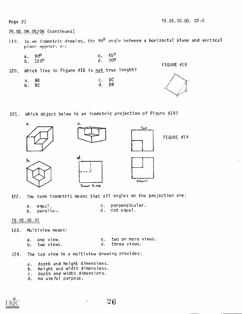
120. Which line in Figure #18 is not true length?
a. ABb. BC
c. DC
d. DB
FIGURE #18
121. Which object below is an isometric projection of Figure #19?
a. c.
d.
k 4HT Sloe
To r
CRoar
FIGURE #19
122. The term isometric means that all angles on the projection are:
a. equal.b. parallel.
79.01.05,01
123. Multiview means:
a. one view.b. two views.
c. perpendicular.d. not equal.
c. two or more views.d. three views.
124. The top view in a multiview drawing provides:
a. depth and height dimensions.b. height and width dimensions.c. depth and width dimensions.d. no useful purpose.
4)

Page 22
79.01.05.01 (continued)
125. The top, front and bottom views are:
a. aligned horizontally and are the same height.
b. aligned vertically and are the same height.
c. aligned horizontally and are the same width.
d. aligned vertically and are the same width.
126. Depth dimensions in the top and right side views:
79.01.00.00. C2-0
a. must correspond in the front and back.b. must correspond with the bottom and left side views.
c. must correspond in all the views.d. do not correspond in any view.
127. All points on a view will:
a. 1roject to all other remaining views.
b. be visible points on the remaining views.c. cannot be located on the remaining views.d. be hidden points on the remaining views.
79.01.05.02
128. Which object below is drawn correctly?
a. b.
129. The views necessary to completely describe the object shown in Figure #20 are:FIGURE #20
a. 1, 3, and 6.b. 1, 6, and 7.c. 1 and 4.
d. 1 and 3.

Page 23
79.01.05.02 (continued)
130. The top view of Figure #21 looks like:
a.
b.
79.01.05.03/04
c.
d.
none ofthese.
79.01.00.00. C2-0
FIGURE #21
131. The type of reproduction process used in this class is:
a. blueprinting.b. diazo printing.
c. lithograph.
d. Xeroxing
132. Which speed of paper must b4/460
a. 10 c.00 5
b. 7
the slrest machine speed?it
d. print paper
133. If a print comes out with blue background, you should:
a. darken the lines.b. erase the background.c. speed the machine up.d. slow the machine down.
134. Which combination of line and material requires the slowest speed setting
on the machine?
a. ink, mylar, and speed 9 paper.b. ink, vellum, and speed 10 paper.c. pencil, mylar, and speed 9 paper.d. pencil, vellum, and speed 10 paper.
135. The reproduction process we use takes how many steps?
a. 1 c. 3
b. 2 d. 4

Page 24
79.01.06.01-.04
136. The best method of dimensioning is:
a. b.
I
I I I
I
79.01.00.00. C2-0
d. all are equally,good.
I 1
I /1__1_-4 -
137. The correct way to dimension a cylindrical object is:
138. Line 2 in Figure #22 is:
a. a dimension line.b. an extension line.c. a continuation line.d. an object line.
c.
139. The size dimensions shown in Figure #23 are:
a. C, D, E, and F.b. A, D, E, and F.c. B, D, E, F, and G.d. all dimensions are size dimensions.
29
®
FIGURE #22
FIGURE #23
14-'1
h -1

Page 25
79.01.06.01-.04 (continued)
140. The location dimensions in Figure #23 are:
a. D & Bb. A & C
c. A & Bd. E & F
79.01.00.00. C2-0
141. Drawings should be made to scale, and the scale should be indicated:
a. on the object.b. in the title block.c. outside the border line.d. only when smaller than full scale.
142. Dimensions are given in the form of:
a. linear distances, angles, or notes.b. fractions only.c. decimals only.d. arrowheads.
143. If all dimensions are read from the bottom of the sheet, it is:
a. dimensioned poorly.b. confusing.c. the aligned method.
.d. the unidirectional method.
144. Which line below is not a type of line used as a dimension line?
a. extensionb. center
c. leaderd. hidden
145. The dimensions shown in Figure #24 are
a. equal
b. shapec. size
d. location
dimensions.FIGURE #24

Page 26
79.01.07.01-.09
146. The sectional view illustrated in Figure #25 is:
a. a turned section.b. a removed section.c. a revolved section.d. a center section.
79.01.00.00. C2-0
FIGURE #25
147. The sectional view produced according to plane A in Figure #26 would be:
a. an alternate section.b. a half section.c. an auxiliary section.d. a full section.
148. The sectional view illustrated in Figure #27 is:
a. a full section.b. a one-fourth section.c. a broken-out section.d. a half section.
149. The correct sectional view of the Figure #28 is:
a. b. c.
FIGURE #26
FIGURE #27
d.
FIGURE #28
Page 27
79.01.07.01-.09 (continued)
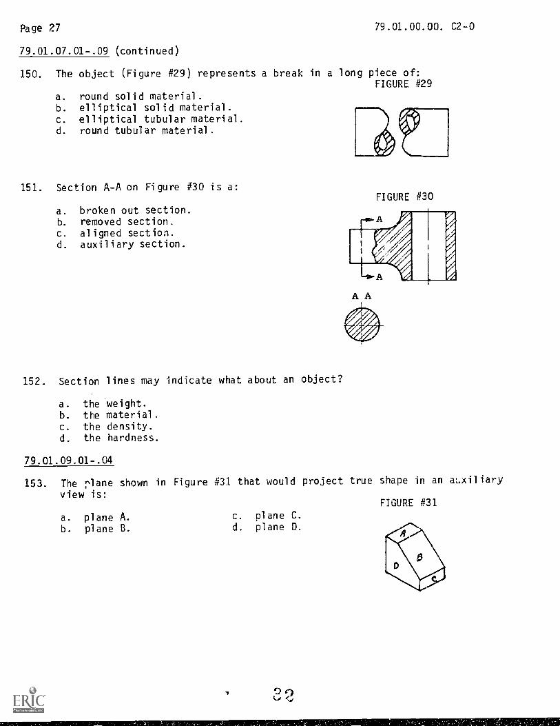
150. The object (Figure #29) represents a break in a long piece of:FIGURE #29
79.01.00.00. C2-0
a. round solid material.b. elliptical solid material.c. elliptical tubular material.d. round tubular material.
151. Section A-A on Figure #30 is a:
a. broken out section.b. removed section,c. aligned section.d. auxiliary section.
152. Section lines may indicate what about an object?
a. the weight.b. the material.c. the density.d. the hardness.
FIGURE #30
A A
79.01.09.01-.04
153. The rlane shown in Figure #31 that would project true shape in an auxiliary
view is:FIGURE #31
a. plane A. c. plane C.
b. plane B. d. plane D.

Page 28 79.01.00.00 C2-0
79.01.09.01-.04 (continued)
154. An auxiliary v;ew is a view which shows an angle surface:
a. from the side.b. as a skewed plane.c. true size and shape.d. from above.
155. The plane that would project true shape in the rear view of Figure #31 is:
a. plane D. c. plane B.
b. plane A. d. plane C.
156. The Plane DEH shown in Figure #32 will project true shape in:FIGURE #32
a. an auxiliary view.b. the top view.c. the right side view.d. the front view.
157. Plane CGFHE shown in Figure #32 will project true shape in:
a. the right side view.b. the front view.c. the top view.d. an auxiliary view.
79.01.09.05
158. A secondary auxiliary view is projected from which view?
a. primary auxiliary view.b. right side view.c. front elevation view.d. top view.
159. A secondary auxiliary view is often necessary to show true size and shape of a(n):
a. line.
b. perpendicular surface.c. angled surface.d. skewed surface.
t) 3

Page 29 79.01.00.00. C2-0
79.01.10.01-.04
160. Which of the following are the four commonly used types of templates.
a. symbols, tapes, shapes, and heat.b. stencils, outlines, burnishers, and letters.c. burnishers, outlines,_guides, and stencils.d. pressure, symbols, shapes, and objects.
161. Which of the objects below are not commonly drawn with templates?
a. map symbols.b. electronic symbols.c. economic symbols.d. architectural symbols.
162. Which is not a reason to use templates?
a. they speed up the drawing.b. they are much more accurate than other methods.c. there is such a large variety of templates.d. they work well on repetative objects.
79.01.11.01
163. In an isometric drawing, angle R, shown in Figure #33 is:FIGURE #33
a. 60 degrees.b. 25 degrees.c. 20 degrees.d. 30 degrees.
164. In an isometric drawing, the number of principal views shown is:
a. fourb. two
c. oned. three
165. The type of axonometric projection shown in Figure #34 is:FIGURE #34
a. isometric.b. dimetric.c. trimetric.d. none of these.
A = B = C
Page 30
79.01.11.01 (continued)
166. Measurements on an isometric drawing should be made:
a. vertical or horizontal.
b. with a metric scale.c. parallel to the isometric axis.d. so they are reduced by four-fifths.
167. All lines parallel to the isometric axis are:
a. perpendicular to the plane.
b. drawn true length.c. angled surfaces.d. drawn half size.
79.01.11.02/03
168. The receding axis in an oblique drawing is drawn at:
a. an angle of 120 degrees to the other axis.
b. 90 degrees to horizontal.c. 90 degrees to vertical.d. any angle between 15 degrees and 75 degrees.
i69. A cavalier drawing is a type of:
a. oblique projection.b. axonometric projection.c. orthographic projecion.d. perspective drawing.
79.01.00.00. C2-0
170. When drawing a cabinet oblique, the angle that the projectors make with the
plane of projection is always:
a. an oblique angle.b. parallel.c. 45 degrees.d. 1.20 degrees.
171. When the receding lines are drawn to half size, the drawing is:
a. a cabinet projection.b. a cavalier projection.c. an orthographic projection.d. a half-scale projection.
172. On an oblique drawing, the object is positioned so most of the arcs appear in:
a. the top plane. c. the left plane.
b. the front Plane. d. the right plane.

Page 3179.01.00.00. C2-0
79.01.11.02/03 (continued)
173. When drawing a cavalier drawing, the object is positioned so the profile
view is shown:
a. true size and shape.
b. at an angle to the front.
c. in the top view.
d. in sections.
79.01.11.04/05
174. The first step in drawing an orthographic method perspective is to:
a. draw the top and front view.
b. draw the visual rays.
c. draw the parellels.d. draw the vanishing point.
175. In a one-point perspective with the front surface on the picture plane,
which dimensions are true size?
a. all of them.
b. the height and width.
c. the height and depth.
d. the width and depth.
176. In a two-point perspective, which dimension(s) is true length on the
picture plane?
a. height.
b. depth.
c. width.
d. all of them.
177. The plane upon which a perspective view is projected is called:
a. the perspective plane.b. the projection plane.
c. the pis:.L;r2 plane.
d. the orthographic plane.
178. The position of the observer when looking at an object in perspective is called:
a. the vanishing point.b. the picture plane.c. the projection point.d. the station point.
9 6
Page 32 79.01.00.00. C2-9
'79.01.11.04/05 (continued)
179. When drawing a one point perspective using the orthographic method, the stationpoint must be where with regard to the vanishing point?
a. to the left of.b. to the right of.c. on a horizontal line with.d. on a vertical line with.
79.01.12.01-04
180. Given a traverse S 36° 15' E from a point, which traverse below would bethe same line?
a. N 360 15' W c. N 53° 45' Wb. N 36° 15' E d. S 53° 45' E
181. Which bit of information listed below 'in not contained on a plat?
a. station points.b. land owner.c. elevations.d. directions and length of boundries.
182. What does the following notation represent: (sta 413 0 FAP)
a. a fast action point.b. a closed traverse.c. a field transit symbol.d. a reference point for measuring.
183. A map grid is used for what purpose?
a. to find station points.b. to locate the transit.c. to locate elevations.d. to find traverses.
184. Any point on a given contour line:
a. is on the map grid.b. has a different height then the next point.c. is equal distance from the next contour line.d. is the same height as all points on the contour line.

Page 3379.01.00.00. C2-0
79.01.13.01-07
185. When drawing developments, the lengths of lines to use are:
a. the lengths from the front view.
b. the lengths from the top view.
c. their true lengths.d. exactly one-half scale.
186. The drawing of all of the surfaces of an object to make a pattern is called:
a. auxiliary drawing. c. surface drawing.
b. intersection. d. development.
187. A prism with lateral edges that are not perpendicular to its base is:
a. a right prism. c. a truncated cone.
b. an oblique prism. d. a pipe offset.
188. Which of the following is the proper method of developing a cone?
a. triangulation. c. radial line.
b. parallel line. d. perpendicular line.
189. Which of the following is the proper method of developing a cylinder?
a. triangulation. c. radial line.
b. parallel line. d. perpendicular line.
79.01.14.01
190. Which of the following is not a design quality?
a. function c. shop processes
b. asthetics d. all are design qualities
191. Which of these objkts listed below are concerned more with asthetics
then functiun?
a. pictures, statues, and paintings.
b. chairs, tables, and desks.
c. buildings, autos, and planes.
d. stereos, radios, and clocks.
79.01.14.02
192. The detail drawing usually consists of:
a. isometric views with the dimensions.
b. dimensioned orthographic views.
c. orthographic views without dimensions.
d. isometric views without dimensions.

Page 34
79.01.14.02 (continued)
193. Details of several parts of an assembly may be drawn on one sheet:
79.01.00.00. C2-0
a. in patents drawings only.b. on the assembly drawing.c. if space permits.d. at no time.
194. All necessary information not given directly on the detailed drawing with
notes and dimensions must be shown in:
a. the assembly drawing.b. the bill of materials.c. the title block.d. none of the above.
79.01.14.03
195. The following are four general types of assembly drawings. Which one does
not show hidden lines and minor details?
a. general assemblies (exploded).b. working drawing assemblies (dr,tail).c. installation assemblies (outline).d. design assemblies (layout).
196. The working drawing assembly is:
a. drawn in isometric.b. very detailed with all the hidden lines.
c. drawn orthographic without the hidden lines.d. not drawn as a rule.
197. The title strip should contain:
a. the drawing title, company name, sheet #, date, and draftsperson's name.
b. all in7urmation on the size of the object.
c. the name of the drawing and nothing else.d. all the materials needed for the object.
79.01.14.04
198. The bill of materials contains:
a. the different materials and their cost.
b. the name of the object and the draftsperson who drew it.
c. information not contained on the detailed drawing.
d. the cost of the object.

Page 35 79.01.00.00. C2-0
79.01.14.04 (continued)
199. Drawings that are line shaded, lettered in script, and protect a
manufacturer are called:
a. security drawings. c. detailed drawings.
b. old style drawings. d. patent drawings.
200. The general assembly (exploded view) drawing is done as a(n):
a. cabinet drawing.b. two-point perspective drawing.c. oblique drawing.d. isometric drawing.
CONGRATULATIONSYOU
MADEIT!

79.01.00.00. C2-0November 26, 1979
BASIC DRAWINGCOURSE PRE/POST TEST
79.01.01.01 79.01.01.07 79.01.02.03
1. B 31. B 61. A
2. C 32. D 62. B
3. D 33. D 63. B
4. D 34. C 64. D
5. D 35. B 65. C
79.01.01.02 79.01.01.08 79.01.03.01
6. D 36. B 66. D
7. D 37. B 67. B
8. D 38. A
9. A 39. B 79.01.03.02
10. D 40. D
79.01.01.03 79.01.01.09
68. A69. D
11. B 41. D 79.01.03.03
12. B 42. B
13. A 43. C 70. C
14. D 44. B 71. D
15. C 45. D
79.01.01.04 79.01.01.10
79.01.03.04
72. C
16. B 46. A 73. A
17. D 47. D
18. C 48. D 79.01.03.05
19. B 49. A
20. B 50. B 74. D
75. P
79.01.01.05 79.01.02.0179.01.03.06
21. A 51. B
22. C 52. C 76. C
23. A 53. D 77. C
24. C 54. A
25. D 5. B /9.01.03.07
79.01.01.06 79.01.02.02 78. C
79. A
26. D 56. D
27. D 57. D 79.01.03.08
28. A 58. A
29. B 59. B 80. B
30. D 60. C 81. C
41

Page 2
79.01.00.00. C2-0Test Key
79.01.03.09 79.01.03.21 79.01.05.03/04
82. B
83. D
79.01.03.10
100. B
101. D
102. C
103. D
104. C
79.01.03.22
131. B
132. C
133. D
134. A
135. B
79.01.06.01-0484,85.
C
A
79.01.03.11 105. 136. A137. A
86. B 79.01.04.01 138. A
87. C139. C
106. A 140. B
79.01.03.12/13 107. C 141. B
108. B 142. A
88. B 109. C 143. D
89. C 110. C 144. D
90. D145. D
79.01.04.02/03
79.01.03.14111. A
79.01.07.01-09
91. C 112. D 146. C
92. D 113. C 147. D
114. C 148. D
79.01.03.15 115. A 149. A150. D
93. A 79.01.04.04 151. B
94. 8152. B
79.01.03.16
116. B
117. B 79.01.09.01-04
95. D 79.01.04.05/06 153.154.
B
C
79.01.03.17 118. D 155. A
119. B 156. A
96. A 120. D 157. A
121. B
79.01.03.18 122. A 79.01.09.05
97. A 79.01.05.01 158. A159. D
79.01.03.19 123. C
124. C 79.01.10.01-04
98. C125. 0
126. B 160. C
79.01.03.20 127. A 161. C
162. B
99. A 79.01.05...02
12R. C
129. A
130. C
Page 3
79.01.11.01 79.01.14.01
163. D 190. D
164. D 191. A
165. A
166. C 79.01.14.02
167. B
79.01.11.02/03
192. B
193. C
194. B
168. D
169. A 79.01.14.03
170. C
171. A 195. C
172. B 196. B
173. A 197. A
79.01.11.04/05 79.01.14.04
174. A 198. C
175. B 199. D
176. A 200. D
177. C
178. D
179. D
79.01.12.01-04
180. A
181. C
182. D
183. C
184. D
79.01.13.01-04
185. C
186. D
187. 8
188. C
189. B
79.01.00.00. C2-0Test Key

File Code:79.01.01.00:A2-1
101---t Family Published:10-7-77
Ethwatiat Revised: 8-14-79
Program 11,cgo vm hag Nap Giv tica le® ®Iag
UNIT: MECHANICAL DRAWING
RATIONALE:
In our technical society, there is a need for concise and clear communication. The graphic
language is perhaps the best method for communicating ideas for industry. Even if you are
only indirectly associated with industry, a knowledge of the graphic language is essential
in order for you to read and draw blueprints. Confucius once said, "One picture is worth
a thousand words." If you don't believe this, try telling someone how to build a house,
or any object without using drawing.
PREREQUISITES:
Same as the course (see the course LEG).
OBJECTIVES:
Identify the types of lines and drafting instruments.Use drafting instruments to measure and draw lines conforming to ANSI standards.
RESOURCES:
Printed Materials
Basic Technical Drawing, Spencer and Dygdon, Macmillan Company, New York, 1q6B.
Engineering Drawing and Graphic Technology. French and Vierck, Eleventh Edition, McGraw-
Hill Book Company, New York.Mechanical Drawing. French and Svenson, Webster Division, McGraw-Hill Book Company, New York.
Technical Drawing. Sixth Edition, Giesecke, Mitchell, Spencer and Hill, Macmillan Company,
New York.
Equipment
Basic Drafting Tools: As indicated in the Course LEG.
GENERAL INSTRUCTIONS:
This unit consists of ten Learning Activity Packages (LAPs). Each LAP All provide specific
information for completion of a learning activity.
The general procedure for this unit is as follows:
1) View the resource filmstrips/and/or/video cassette.2) Read the first assigned LAP.3) Begin and complete the first assigned LAP.
Principal Author(a): C. We tterl ing
Revised: J. Wheatley
Family Training Center. Inc.7 4...4

Page 2 79.01.01.00:A2-1
GENERAL INSTRUCTIONS: (continued)
4) Take and score the LAP test if indicated in the LAP.5) Determine the reason for any missed items on the LAP test.6) Proceed to and complete the next assigned LAP in the unit.7) Complete all required LAPs for the unit by following steps 3 through 6.
8) In this unit, there are some LAPs that have tests combined with other LAP tests. These
combined tests are taken after completing the last LAP covered by the test.
9) Take the unit tests as described in the Unit LEG "Evaluation Procedures".
10) Proceed to the next assigned unit.
PERFORMANCE ACTIVITIES:
.01 Identifying Drawing Leads and Line Weights.
. 02 Mounting Paper on a Drawing Board.
.03 Drawing Horizontal Lines.
.04 Drawing Vertical Lines.
.05 Using the Engineer's Scale.. 06 Centering Two-View Drawings.. 07 Centering Three-View Drawings.. 08 Inking Techniques..09 Precedence of Lines..10 Applying Basic Mechanical Drawing Techniques.
EVALUATION PROCEDURE:
1. The student takes a multiple-choice unit post test and turns it in for evaluation, Suc-
cess completion is a score of 80% or better.
2. The student takes a performance test.
Successful unit completion is meeting the listed criteria for the performance test.
FOLLOW-THROUGH:
Principles of measuring, line work and neatness will be used throughout the remainder of
the course.
Begin the first asi^n.:e, LAP after firs* reading Chapters 1 through 3 in Basic Technical
Drawing and viewing filmstrip/video cassette on Introduction to Drafting - unit 1.
/15

ountain-Plaina Education &Gnomic Dave loPment
Program, Inc., ---
Glasgow AFB. Morilani"-&9231
79.01.01.01.
Student File Code: 70.01 - A2-2.
Date: Date Published 6/18/74
UNIT PRETEST: MECHANICAL DRAWING
1. Examples of hard leads are:
a. 2B,2H,2F.b. 2H,H,HB.c. 2B,4B,6B.d. 8H,6H,4H.
2. Examples of medium leads are:
a. 8H,6H,4H.b. 2B,4B,6B.c. 2H,H,HB.d. 2B,2H,2F.
3. Examples of soft leads are:
a. 8H,6H,4H.b. 2B,4B,6B.c. 2H,H,HB.d. 2B,2H,2F.
4. Line A in figure at right is:
a. an outline.b. a sold line.c. a visible line.d. an exterior lime.
5. Line B in figure at right is:
a. a cutting plane line.b. a section line.c. a center line.d. an object line.
79.01.01.02.
79.01.01.00. A2-2
6. Left-handers should place the head of the T-square:
a. on the right-hand side of the drawing board.b. on the bottom edge of the drawing board.c . on the left-hand side of the drawing board.d. on the top edge of the drawing board.
7. Right-handers should place the head of the T-square:
a. on the left-hand side of the drawing board.b. on the bottom edge of the drawing board.c. on the top edge of the drawing board.d. on the right-hand side of the drawing board,
8. The working edge of the T-square is used to
a. align the drawing paper.b. clean the pencil.c. scrape off the board.d. adjust the compass.
9. When using thumb tacks, use the type with:
a. extra long nail.b. serrated brad.c. thin smooth head.d. no head.
10. When mounting paper to the board, align the:
eige of the paper.b. top edge of the paper.c. right edge of the paper.d. bottom edge of the paper.
ry

79.01.01.00. A2-2
79.01.01.03.
11 When drawing horizontal lines, left-handers:
a. follow the same procedure as right-handers.b. reverse the procedure for right-handers.c. follow any procedure desired.d. have no procedure to follow.
12. A horizontal line is drawn from:
a. from left to right or right to left.b. left to right if you are left handed.c. right to left if you are right handed.d. right to left if you are left handed.
13. To maintain a symmetrical pencil point when drawing horizontallines:
a. hold the pencil tightly and do not rotate it.b. rotate the pencil slowly.c. rotate the pencil as rapidly as possible.d, turn the pencil from side to side.
14. The type of line drawn along the top of the T-square is:
a. horizontal.b. vertical.c. curved.d. circles and arcs.
15. When drawing horizontal lines, the trail of graphite particles are:
a. left where they fall.b. rubbed into the paper.c. removed by eraser.d. blown off at intervals.
79.01.01.04.
16. When drawing vert'cal lines, left-handers:
a. have no procedure to follow.h. follow the' ,;ame procedure as right -hancier11.
c. follow any procedure det;ired.d. reverse the procedure for right-handers.
79.01.01.00. A2-2
79.01.01.04. continued:
17. A vertical line is drawn:
a. top to bottom if you are right handed.b. top to bottom if you are left handed.c. bottom to top if you are left handed.d. either top to bottom or bottom to top.
18. To maintain a symmetrical pencil point when drawing vertical lines:
a. turn the pencil from side to side.b. hold the pencil tightly and do not rotate it.c. rotate the pencil as rapidly as possible.d. rotate the pencil slowly.
19. When drawing vertical lines, the pencil point is held:
a. with an eraser.b. by the finger tips.c. against sandpaper.d. a small space from the triangle.
20. When drawing vertical lines, the trail of graphite particles are:
a. left where they fail.b. rubbed into the paper.c, remove by eraser.d. blown ofF at intervals.
79.01.01.05.
79 .01.01 .05 . continued:
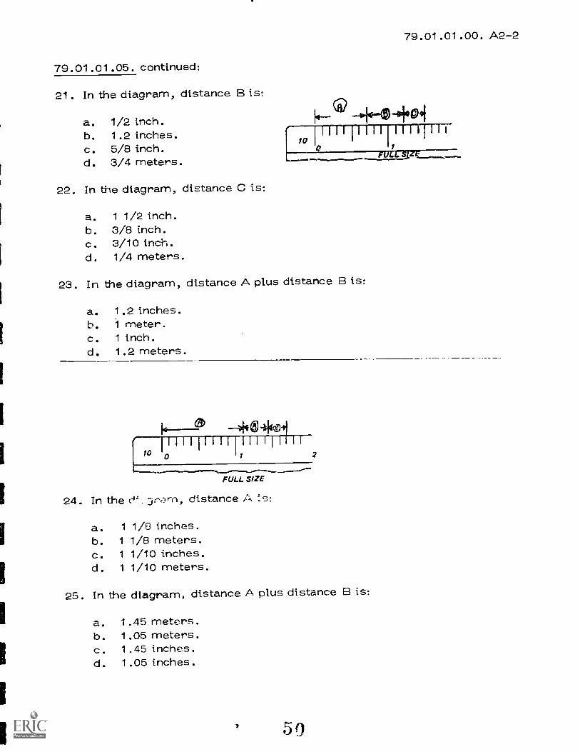
21. In the diagram, distance B is:
a. 1/2 inch.b. 1.2 inches.c. 5/8 inch.d. 3/4 meters.
22. In the diagram, distance C is:
a. 1 1/2 inch.b. 3/8 inch.c. 3/10 inch.d. 1/4 meters.
79.01.01.00. A2-2
-+-6-01.091
0 11RILE S IF
23. In the diagram, distance A plus distance la is:
a. 1.2 inches.b. 1 meter.c. 1 inch.d. 1.2 meters.
--4qa( 111111111111i11111{
10 10 11 2
FULL SIZE
24. In the (-4:_ 0, rzir-n, distance A (3:
a. 1 1/8 inches.b. 1 1/8 meters.c. 1 1/10 inches.d. 1 1/10 meters.
25. In the diagram, distance A plus distance B is:
a. 1.45 meters.b. 1.05 meters.c. 1.45 inches.d. 1.05 inches.
59

79.01.01.06.
26.
De fa..3d+1
,a.
26. When centering a two view drawing:
a. distance B always equals distance C.
b. distance B always equals distance G.
c. distance B is always equal to distance A.
d. distance B can be any length you decide.
79.01.01.00. A2-2
27. When spacing a two-view drawing, the width of the top and front viewsis:
a. different by 1 inch.b. the same.c. different by 2 inches.d. different by 3 inches.
28. When drawing a two-view drawing, the first step is to:
a. determine the spacing between the views.b. draw horizontal construction lines.c. draw vertical construction lines.d. draw circles = J arcs.
:11

79.01.01.00. A2-2
79.01.01.06. continued:
29. In a two-view drawing, corners of construction lines should:
a. not be seen.b. just meet.c. not touch.d. cross.
30. The last step in making a two-view drawing is to:
a. locate the center lines.b. erase the construction lines.c. heavy-in all final lines.d. make short marks to locate the views.
79.01.01.07.
31. When centering a three-view drawing:
a. distance H and G are always equal.b. distance D and C are always equal.c. distance D and F are always equal.d. distance A,F, and C are always equal.

79.01.01.00. A2-2
79.01.01.07.
32. The formula for horizontal spacing is:
a. A plus B plus C divided by 3.
b. I minus (2 times K) divided by 2.
c. A plus B plus C divided by 2.
d. I minus (K plus H plus B) divided by 2.
33. When spacing a three-view drawing, the width of the top and frontviews is:
a. different by 1 inch.b. the same.c. different by 2 inches.d. different by 3 inches.
34. The first step in drawing a three-view drawing is to:
a. draw circles and arcs.b. draw horizontal lines.c. draw vertical lines.d. determine the spacing.
35. Corners of construction lines in three-view drawings should:
a. not be seen.b. just meet.c. not touch.d. cross.
79.01.01.0P
36. When inking or tracing a pencil line, the ink line should be:
a. above the pencil line.b. centered over the pencil line.c. below the pencil line.d. longer than the pencil line.
37. The first lines to ink on a drawing are:
a. construction lines.b. hidden lines.c. circles and arcs.d. section lines.
53
79.01.01.00. A2-2
79.01.01.08. continued:
38. When drawing ink lines, the technical fountain pen should be:
a. at an angle of 90° to the paper in the direction of the line.b. at an angle of 60° to the paper in the direction of the line.c. at any angle that is comfortable.d. at an angle of 45 to the paper in the direction of the line.
39. Ink lettering on a drawing is done:
a. first.b. last.c. sometime in the middle.d. any time it is convenient.
40. The ruling pen is sharpened with:
a. sandpaper.b. a hard Arkansas oil stone.c. an electric pen sharpener.d. a regular penc:l sharpener.
79.01.01.09.
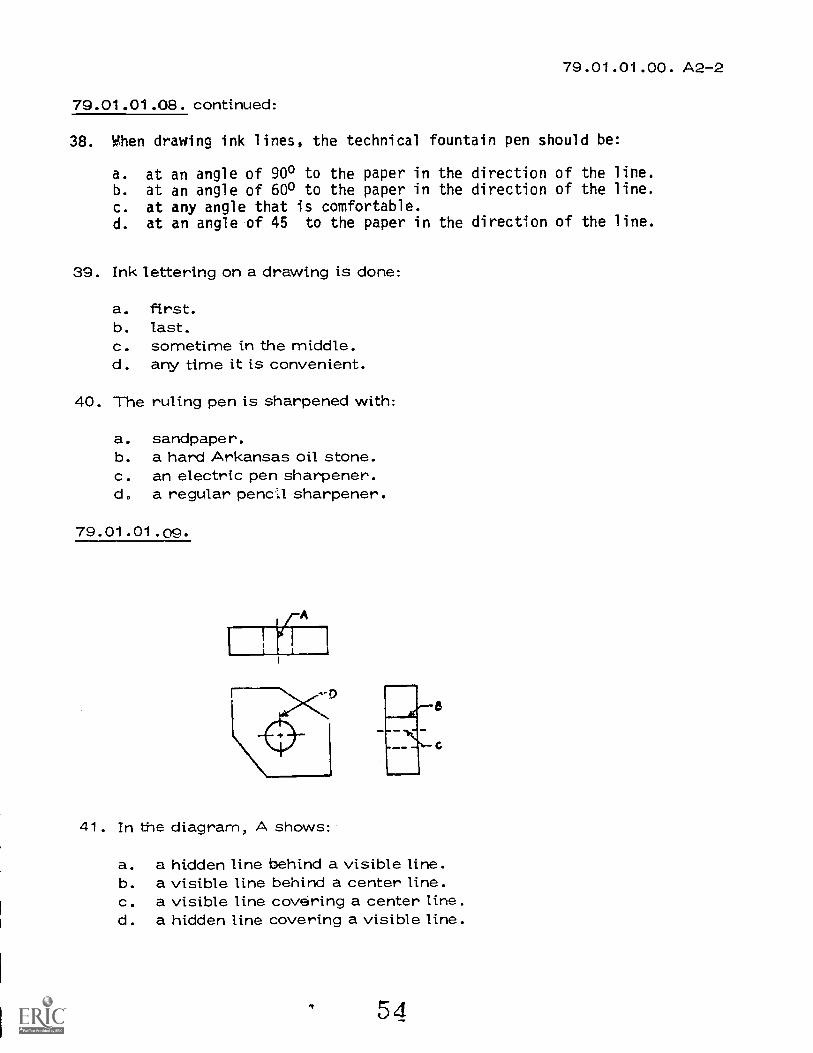
41. In the diagram, A shows:
a. a hidden line behind a visible line.b. a visible line behind a center line.c. a visible line covering a center line.d. a hidden line covering a visible line.
54

79.01.01.00. A2-2
79.01.01.09.
42. In the diagram, C shows:
a. a visible line covering a hidden line.b. a hidden line covering a center line.c. a hidden line covering a visible line.d. a visible line covering a center line.
43. In the diagram, D is a:
a. visible line.b. hidden line.c. construction line.d. center line.
44. A visible line always takes precedence over a:
a. center line or hidden line.b. circle or arc.c. border line.d. title block.
45. A hidden line always takes precedence over a:
a.
b.c.d.
circle or arc.visible line.center line.border line.
79.01.01.10.
46. Object-!._:s in drafting are.:
a. accuracy, speed, legibility, and neatness.b. equipment, instruments, books, and pencils.c. reading, slow drawing, ink, and text books.d. neat drawings, slow work, and no accuracy.
47. The Parallel-Ruling Straightedge is used for:
a. large drawings.b. small drawings.c. vertical lines.d. 'circles and arcs.

79.01.01.00. A2-2
79.01.01.10. continued:
48. To replace the T-square, triangles, scales, and protractor use a:
a. parallel-ruling straightedge.b. template.c drafting machine.d. mylar sheet.
49. To draw mechanical curves other than circles or circular arcs, use
a:
a. compass.b. electric eraser.c. drafting machine.d. french curve.
50. To make accurate measurements:
a. take measurements directly off the scale with dividers or compass.
b. place the scale on the drawing and make short dashes at right
angles to the scale.c. use a ruler.d. set off distances individually by moving the scale to a new position
each time.
5f

79.01.01.00. A2-2
LAP
UNIT PRETEST ANSWER KEY: MECHANICAL
LAP
DRAWING
01 1. D 08 36. B2. C 37, C3. B 38. A
4. C 39. B5. B 40. B
02 6. A 09 41. C
7. A 42. B8. A 43. D9. C 44. A
10. B 45. C
03 11. B 10 46. A12, D 47. A13. B 48. C14. A 49. D
15. D 50. B
04 16. D17. D
18. D19. D20. D
05 21. A22. C23. A2425. C
06 26. C27. B28. A29. D30. C
07 31. D32. D33. 934. D35. D
IV 57
Mountain-Plaine F.dueetton &Economic- Development
Progr.m. Inc.
(Hugow A1' H, Montero' 59211
PERFORMANCE ACTIVITY.
OBJECTIVES:
File Code.79.01.01.01. A2-0
DatePublis4d. 10/7/77
Revised: 8-14-79
Learning Activity PackageStudent:
Oate:
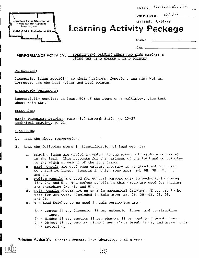
IDENTIFYING DRAWING LEADS AND LINE WEIGHTSUSING THE LEAD HOLDER & LEAD POINTER
Categorize leads according to their hardness, function, and Line Weight.Correctly use the Lead Holder and Lead Pointer.
EVALUATION PROCEDURE:
Successfully complete at least 80% of the items on a multiple-choice testabout this LAP.
RESOURCES:
Basic Technical Drawing, para. 3.7 through 3.10, pp. 23-25.Technical Drawing, p. 23.
PROCEDURE:
1. Read the above resource(s).
2. Read the following steps in identification of lead weights:
a. Drawing leads are graded according to the amount of graphite containedin the lead. This accounts for the hardness of the lead and contributesto the width or weight of the line drawn.
b. Hard pencils are used when extreme accuracy is required and for basicconstruction lines. Pencils in this group are: 9H, 8H, 7H, 6H, 5H,and 4H.
c. Medium pencils are used for general purpose work in mechanical drawing(3H, 2H, and H). The softer pencils in this group are used for shadingand sketching (F, HB, and B).
d. Soft pencils should not be used in mechanical drawing. These are to beused for art work. Included in this group are 2B, 3B, 4B, 5B, 6B,and 7B.
e. The Lead Weights to be used in this curriculum are:
6H Center lines, dimension lines, extension lines, and constructionlines
4H - Hidden lines, section lines, phantom lint's, and long break lines.2H - Object lines, cutting plane lines, short break lines, and arrow heads.
II - Lettering.
Principal Author(s): Charles Dvorak, Jere Wheatley, Sheila Voson

Page 2 79.01.01.01:A2-0
f. Suggested contrasts in line weight in ink (refer to Figure 2.16, page 23,Technical Drawing or Figure 3-11, page 26, Basic Technical Drawing), mayalso be applied to width of lines in lead. Notice that all lines maintainthe same blackness. It is only the width which changes in order to createcontrast for lines.
NOTE: These lead weights are suggested as a guideline for draftspersons becomingfamiliar with leads and line weights for the first time. Individually, youmay find that the pressure you apply to the lead holder requires that youuse a harder or softer lead than those suggested above. Part of becominga draftsperson is learning what is best for you.
3. Obtain a set of drawing leads and holder case from the instructor.
KEYPOINT: Remember the softer the pencil lead, the more it will smudge.
4. Read the following summary:
a. Insert a lead in the lead holder. Use your thumb to apply pressure to
the button at the top. This will expand the collet for the lead.b. Extend the lead 3/8" to 1/2" out of the holder.c. Insert the lead and lead holder into the lead pointer and rotate.
(Different colored sleeves are used to identify the size of openingin the lead pointer).
5. Take the LAP test.
ti 59

1.
Student: File Code: 79.01.01.01.A2-2
Gate: Bate Published: 10/7/77
LAP TEST: IDENTIFY DRAWING LEADS AND LINE WEIGHTS
Drawing leads are graded according to:
a. the amount of graphite contained in the lead.b. letters of the alphabet (A, B, C, D, etc.) only.c. numbers (1, 2, 3, 4, etc.) only.d. the length of the pencil.
2. Hard leads are used:
a. for general purpose work in mechanical drawing.b. when extreme accuracy is required for basic construction lines.c. for art work but not mechanical drawing.d. only on hard paper.
3. Medium leads are used:
a. only on medium paper.b. when extreme accuracy is required and for basic construction lines.c. for general purpose work in mechanical drawing.d. for art work but not for mechanical drawing.
4. Examples of hard leads are:
a. 2B, 2H, 2F.b. 2H, H, HB.c. 2B, 4B, 6B.d. 8H, 6H, 4H.
5. Examples of medium Icad are:
a. 8H, 6H, 4H.b. 2B, 4B, 6B.c. 3H, 2H, H.d. 2B, 2H, 2F.
6. Examples of soft leads arc:
a. 8H, 6H, 4H.b. 2B, 4B, 6B.c. 2H, H, HB.d. 2B, 2H, 2F.
6
Page 2
7. Construction lines should be made:
a. with H or 2H lead.b. with F or H lead.c. with 6H or 8H lead.d. with B or 2B lead.
8. What length should the lead be extended from the lead holder for sharpening?
a. 1/32" to 1/16".b. 1" to 2".c. 3/8" to 1/2".d. 2" to 3".
9. What identifies the size of opening on the lead pointer issued in your kit?
a. the numbers 1, 2 and 3.b. each sharpener is a different size.c. the colored cap.d. none.
10. Construction lines should be barely seen at:
a. arm's length.b. in the light.c. at 10".d. at 10'.
6 1
79.01.01.01.A2-2

79.01.01.01.A2-2
LAP TEST ANSWER KEY: IDENTIFY DRAWING LEADS AND LINE WEIGHTS
1. A2. B3. C4. D5. C6. B7. C8. C9. C
10. A
FARM
EducationPr Le min 411
79.01.01.02File Code:
11-10-78Date Published:
Revised: 8-14-79
Activity ckageStudent:
Betc
PERFORMANCE ACTIVITY:Mounting Paper on a Drawing Board
OBJECTIVE:
Identify procedure for fastening paper to the drawing board. To identify standard
paper sizes and their relationship.
EVALUATION:
Successfully complete at. least 80% of the items on a multiple-choice test about
this LAP.
RESOURCES:
Basic Technical Drawing, paragraph 3.6, page 22.
PROCEDURE:
1. Read the above resource(s).
2. There are five Standard American Drawing sizes:
a. Size A -- 9 x 12b. Size B --12 x 18c. Size C --18 x 24d. Size D --24 x 36e. Size E --36 x 48
The sizes we use in this class areA, B, -nd C. Our paper stock con-tains ly these sizes.
3. Read the followirJ Key Points:
a. Place paper fairly close (1.--2" to 2") to the working edge of the
drawing board. NOTE: The working edge of the drafting board isthat side which the head of the T-square butts against. For the
right-handed draftsperson it is the left edge of the drafting
board. For the left-handed draftsperson it is the rigt edge.
b. Place a piece tape on the top right (for left-handers) or left
hand corner (for right-handers).
c. Line up paper with T-square. NOTE: Paper is not always cut straight,
therefore, use the straightest edge possible. Use only one edge of
the T-square. Do not use both edges of the T-square. Grip T-square
firmly on drawing board to prevent slipping when lining up paper.
IPrincimi &admi(s): Jere Wheatley
E 3
MISMITIllikh144 glAvatew Mao

,Page 2 79.01.01.02
PROCEDURE: (continued)
d. Put tape
NOTE:
on remaining corners diagonally.
Illustration is for left-
See example
Drawing Board
below:
WorkingEdge
3
paper2
handers.
KEYPOINT: Not all sheets will be fastened securely with only four pieces
of tape. Use as many fasteners as necessary.
4. Take the LAP test.
64

1.
File Code79,01.01.02.A2-2
' fidgefue .
Date: Date Published: 10/7/77
LAP TEST: MOUNTING PAPER ON A DRAWING BOARD
When mounting paper to the drawing board, the top edge of the paper is lined up with:
a. tape and takcs.b. a large triangle.c. the compass geometric method.d. the top (working) edge of the T-square.
2. The paper is held to the board with:
a. nails or brads.b. glue.c. drafting paste.d. staples, thumb tacks or tape.
3. Tracing paper should be fastened:
a. directly to the board.b. only on the back side.c. to the T-square.d. over a drawing already on the board.
4. Paper is attached to the board in which sequence for right handed people:
a. lower right, upper right, lower left, upper left.b. lower left, upper left, lower right, upper right.c. lower right, lower left, upper left, upper right.d. upper left, lower right, upper right, lower left.
5. The working edge of the :rafting board is:
a. on the left-hand side of the drawing board for right handers.b. on the bottom edge of the drawing board for both right and left handers.c. on the top edge of the drawing board fcr both right and left handers.d. on the right-hand side of the drawing board for right handers.
6. If the drawing paper is nut cut straight, it should be:
a. aligned by using the straightest edge possible.b. thrown away.c. used for scratch paper.d. returned to the storage caninet.
65

Page 2 79.01.01.02.A2-2
7. Drawing should be placed:
a. upside down.b. on top of the T-square.c. away from the working edge of the board.d. close to the working edge of the board.
8. When using tape to hold down drawing paper, place it:
a. over the border line.b. outside the border line.c. inside the border line.d. right on the border line.
9. When using thumb tacks, use the type with:
a. extra long nail.b. serrated brad.c. thin smooth head.d. no head.
10. A special draftsman's stapler is used to:
a. attach triangle to T-square.b. staple papers together.c. hammer thumb tacks.d. staple drawing paper to the drawing board.
79.01.01.02.A2-2
LAP TEST ANSWER KEY: MOUNTING PAPER ON A DRAWING BOARD
D2. D3. D4. D5. A6. A7. D8. B
9. C10. D
Mountain-Plains EducationEconomic Lk velopment
Program. Inc.
Glasgow A1,11, M"ntari 69231
File Code:79.01.01.03.A2-0
Date Published:10/7/77
Learning ctivity Package
PERFORMANCE ACTIVITY:DRAWING HORIZONTAL LINES
OBJECTIVE:
Identify the procedure for drawipg horizontal lines.
EVALUATION PROCEDURE:
Studont:
Date:
Successfully complete at least 80% of the items on a multiple-choice test
about this LAP.
RESOURCES:
Basic Technical Drawing, para. 3.11, pg. 25.
PROCEDURE:
1. Read the above resource(s).
2. Read the following summary:
a. Right-handers: Place the T-square head against the left edge of the
board. Left-handers: Place the T-square head against the right edge
cf the board.b. Hold T-square firmly down on paper.
c. Hold lead holder at 600 angle with the paper in the direction of
the line.d. Rotate leaci holder slowly t(., have uniform width in your lines.
e. Move lead holder away from T-square head.
f. Do not use the bottom of the T-square to make lines.
3. Take the LAP test.
Principal Author(s): Charles DvorakSheila Vosen
Jere Wheatley
P

ountaln-Plains Education &onomic Development
Program, Inc.
Glasgow APB. Mon 59231
LAP TEST: DRAWING HORIZONTAL LINES
Student: File Code: 79.01.01.03.A2-2
Date: Date Published:10/7/77
1. To draw a horizontal line, the T-square should be held:
a. at the end of the blade.b. with the compass or dividers.c. loosely and away from the paper.d. firmly and tight against the paper.
2. When drawing horizontal lines, the lead holder should be held:
a. 60 degrees to the paper in the direction of the line.b. 30 degrees to the paper in the direction of the line.c. vertical to the paper in the direction of the line.
d. 45 degrees to the paper in the direction of the line.
3. When drawing horizontal lines, the lead holder should be:
a. turned from side to side.b. held firmly and not rotated.c. rotated as rapidly as possible.d. rotated slowly as you draw the line.
4. When drawing horizontal lines, the head of the T-square is held:
a. on top of the board.b. firmly against tl:e working edge of the board.c. on the bottom of the board.d. loosely.
5. When drawing horizontal lines and great accuracy is required:
a. toe -in the pencil against the T-square.b. sharpen the pencil to a fine point.c. raise the T-square.d. use a harder drawing board.
6, When drawing horizontal lines and the edge of the T-square is too sharp:
a. don't draw the line.b. throw it away.c. use the other side of the T-square.d. sand the edge lightly with No. 00 sandpaper.

Page 2 79.01.01.03.A2-2
7. When drawing horizontal lines, left handers:
a. follow same procedure as right handers.b. reverse the procedure for right handers.c. follow any procedure desired.d. have no procedure to follow.
8. To maintain a symmetrical pencil point when drawing horizontal lines:
a. hold the pencil tightly and do not rotate it.b. rotate the pencil slowly.c. rotate the pencil as rapidly as possible.d. turn the pencil from side to side.
9. When drawing horizontal lines, the pencil point is held:
a. against sandpaper.b. by the finger tips.c. a small space from the T- square.d. with an eraser.
10. When drawing horizontal lines, the trail of graphite particles are:
a. left where they fall.b. rubbed into the paper.c. removed by eraser.d. blown off at intervals.
0

79.01.01.03.A2-2
LAP TEST ANSWER KEY: DRAWING HORIZONTAL LINES
71

Mounts ln-PlAsIng nclucatIon &geranorisi UevrIcipment
Pn,grAtn.
A1:11, 6.1,,rdang 69231
File Code79.01.01.04. A2-0
Date Published10/7/77
Revised: 8-14-79
Learning Activity Package
PERFORMANCE ACTIVITY. DRAWING VERTICAL LINES
OBJECTIVE:
Identify procedures for drawing vertical lines.
EVALUATION PROCEDURE:
Student:
Date:
Successfully complete at least 80% of the its on a multiple-choice test
about this LAP.
RESOURCES:
Basic Technical Drawing, para. 3.12, pg. 26.
PROCEDURE:
1. Read the above resource(s).
2. Read the following summary:
a. Use the T-square and either the 30 x 60 degree or the 45 degree triangle.
b. Place the triangle on the top edge of your T-square as shown in the
illustration below. NOTE: Vertical side of the triangle is toward
the T-square head.
Vertmg/ Edge
c. All vertical lines must be drawn using this method. (You must not slide
the head of the T-square along the top edge of the drawiu., board)
d. Hold T-square and triangle firmly.
C. Wetterling
Principal Author(s): Sheila VosenJer Wheatley
1,c)1,,

page 2 79.01.01.04. A2-0
e. With your lead holder leaning approximately 60 degrees to the paper,draw a line upward. Rotate the lead holder slowly as you draw the
line. NOTE: Rotating the lead holder helps to draw uniform lines.
EXAMPLE:
KEY POINT:
1. For extreme accuracy, use the lead against the lower edge of the triangle.
EXAMPLE: First drawing showing small space between lead holder point and
triangle. Second drawing shows position for greater accuracy.
LEAD HOLDER
TRIANGLE
1 Tokt t lit 11;1 .

not/in-Plains Educationr onomic Development
Gig/goy: APR. Mon---11"-7-13-923-1
Program. Inc.
1.
Student: File Code: 79.01.01.04.A2-2
Date* Date Published- 10/7/7'7
LAP TEST: DRAWING VERTICAL LINES
To draw a vertical line, place the triangle on the T-square with:
a. the vertical edge on the right if you are right handed.b. the vertical edge on the left if you are right handed.c. the vertical edge on the left if you are left handed.d. the vertical edge on either the left or the right.
2. When drawing vertical lines, the lead holder should be held:,
a. 45 degrees to the paper in the direction of the line.b. 60 degrees to the paper in the direction of the line.c. 30 degrees to the paper in the direction of the line.d. vertical to the paper in the direction of the line.
3. A vertical line is drawn from:
bottom to top if you are right handed.top to bottom if you are right handed.
c. top to bottom if you are left handed.d. either top or bottom.
4. When drawing vertical lines, the lead holder should be:
a. held firmly and not rotated.b. turned from side to side.c. rotated as rapidly as possible.d. rotated slowly.
5. When drawing vertical lines and great accuracy is required:
a. toe-in the lead holder against the T-square.b. toe-in the lead holder against the triangle.c. use a harder drawing board.d. raise the triangle.
6. When drawing vertical lines, left handers:
a. have no procedure to follow.b. follow the same procedure as right handers.c. follow any procedure desired.d. reverse the procedure for right handers.

Page 2 79.01.01.04.A2-2
7. When drawing vertical lines, the T-square should be held:
a. loosely and away from the paper.b. at the end of the blade.c. with the compass or dividers.d. firmly and tightly against the paper.
8. A vertical line is drawn:
a. top to bottom if you are right handed.b. top to bottom if you are left handed.c. bottom to top if you are left handed.d. either top or bottom.
9. To maintain a symmetrical lead point when drawing vertical lines:
a. turn the lead holder from side to side.b. hold the lead holder tightly and do not rotate it.c. rotate the lead holder as rapidly as possible.d. rotate the lead holder slowly.
10. When drawing vertical lines, the lead point is held:
a. with an eraser.b. by the finger tips.c. against sandpaper.d. a small space From the triangle.

79.01.01.04.A2-2
LAP TEST ANSWER KEY: DRAWING VERTICAL LINES

hinuntailn-PlitIns F,clucationtrcanumle Development
Progr.m.
Cillaulgow nl N, Niimuiui 602.31
File Code:79.01.01.05 . A2-0
Date Published:10/7/77
Revised: 8-14-79
Learning Activity Package
PERFORMANCE ACTIVITY:USING THE ENGINEER'S SCALE
OBJECTIVE:
Correctly measure given lines using the Engineer's Scale.
EVALUATION PROCEDURE:
Lines measured are without error.
Student:
Date:
Successfully complete at least 80% of the items on a multiple-choice test
about this LAP.
RESOURCES:
Basic Technical Drawing, para. 3.22 and 3.23, pg. 36.
Engineer's Scale.
PROCEDURE:
1. Read the above resource(s).
2. Read the following summary:
a. The Engineer's Scale is set up on the decimal system.
b. Each inch is divided into units of 10, 20, 30, 40, 50, or 60 parts. (Each
division on the 10 scale is .1", 20 scale .05", 30 scale is .033", 40 scale
is .025, 50 scale .02" and 60 scale is .167").
c. To measure 1.6En full size on the Engineer's Scale, the following steps are
taken:
1) Use the 10-scale.
2) Set off one main division.
3) Next, set off 61/2 subdivisions.
Principal Author(s):Charles Dvorak
7 7

Page 2 79.01.01.05. A2-0
4. Do the following:
a. Now measure .750 on the 10-scale by drawing extension lines.
14.750(
WI I 1 I I I I I 1 I I I I I I I
FULL SIZE
b. Now measure 1.375 in the same manner.
1.375
111111111111111iiii[ 10 0 1 2
FULL SIZE
NOTE: To measure a dimension half-size, use the 20-scale.
To measure a dimension one-quarter size, use the 40-scale.
c. Measure the following lines using the 20-scale.
a) 1 c)
b)
d. Measure the same lines using the 40-scale.
5. Check your measurements with the answer key.
6. Return the Engineer's Scale to the instructor.
7. Take the LAP test.
ANSWERS
20 Scale(a)
(b)
(c)
40 Scale(a)
(b)
(c)

17/ountain-Plains Education &
I..' (morale DevelopmentProgram, Inc.
Glasgow APB. Montan a 59281
Student. File Code 79.01.01.05.A2-2
Date: Date Published: 10/7/77
LAP TEST: USING ENGINEER'S SCALE
1. The engineer's scale is graduated in:
a. the vector system.b. the unidirectional system.c. the metric system.d. the decimal system.
2. In the diagram, distance A is:
a. 1.65 inches.b. 1 1/2 inches.c. 2.5 inches.d. 3 1/16 inches.
3. In the diagram, the 10 means:
a. 10 graduations to the inch.b. 10 inches to the graduation.c. a 10 to I scale.d. the scale is 10 inches long.
4. In the diagram, the distance from 0 to 2 is:
a. 2 m;les.b. 2 inclics.c. 2 meters.d. 2 feet.

Page 279.01.01.05.A2-2
5. In the diagram, distance B is:
.5 inch.b. 1.2 inches.c. 5/8 inch.d. .75 meters.
6. In the diagram, distance A plus distance B is:
a. 1.2 inches.b. 1 meter.c. 1 inch.d. 1.2 meters.
7. In the diagram, distance A is:
a. 1 1/8 inches.b. 1 118 meters.c. 1 1/10 inches.d. 1 1/10 meters.
8. In the diagram, distance C is:
a. .37 inches.b. 1/4 inch.e. 25 meters.
I/8 inch.
FULL. SIZE

Page 3 79.01.01.05.A?-2
9. In the diagram, distance A plus distance B is:
a. 1.45 meters.b. 1.05 meters.c. 1.45 inches.d. 1.05 inches.
10. In the diagram, distance A plus distance C is:
a. 1.35 inches.b. 1.35 meters.c. .65 inches.d. .65 meters.
1. D2. A3. A4. B5. A6. A7. C8. B
9. C10. A
79.01.01.05.A2-2
LAP TEST ANSWER KEY: USING THE ENGINEER'S SCALE
82

IFf,;ountain-Plain Education do
irr%*., .onomlc Development
Program, Inc.
Glasgow AFB, 59231k N
-'" LAP TEST: CENTERING TWO-VIEW AND THREE-VIEWDRAWINGS
Student' File Code: 79.01.01.06 - .07.A2-2
Date: Date Published :.:47/77
1. When centering a two-view drawing:
a. distance A can be any length you decide.b. distance A never equals distance B.c. distance A always equals 2 inches.d. distance A always equals distance B.
2. When vertically centering a two-view drawing:
a. distance D equals distance G.b. distance E equals distance A.c. distance C e.,Lials distance D and distance E.d. distance C equals distance E.
Page 2 79.01.01.06. .07.A2.2
3. The formula for horizontal spacing is:
a. 1 minus F divided by 2.b. 1 minus F divided by 3.c. C plus D plus E divided by 2.d. C plus D plus E divided by 3.
4. When spacing a two-view drawing the width of the top and front views is:
a. different by 1 inch.b. the same.c. different by 2 inches.d. different by 3 inches.
5. When drawing a two-view drawing, the first step is to:
a. determine tip: spacing between the views.b. draw horizkmtal construction lines.c. draw vertical construction lines.d. draw circles and arcs.

Page 3
6. When centering a three-view drawing:
a. distance A equals distance C and distance F.b. distance A, B and C arc never equal.c. distance A equals distance B and distance F.d. distance A equals distance C.
7. The formula for vertical spacing is:
79.01.01.06. - .07.A2-2
a. Jqinus (G plus H1 divded by 3.b. A pits B n C divided by 3.c. A plus B plus C divded by 2.d. j minus (G plus E plus H) divded by 2.
8. When spacing a three-view drawing, the width of the top and front views are:
a. different by 1 inch.b. the 'same.c. different by 2 inches.d. different by 3 inches.

Page 4 79.01.01.06. - .07.A2-2
9. The first step in drawing a three-view drawing is to:
a. draw circles and arcs.b. draw horizontal lines.c. draw vertical lines.d. determine the spacing.
10. The formula for horizontal spacing is:
a. I minus (K plus B plus H) divided by 2.b. I minus (A plus B plus C) divided by 2.c. (A plus K plus B plus H plus C) divided by 3.d. J minus (K plus H) divided by 3.

79.0I.01.06.A2-279.01.01.07.A2-2
LAP TEST ANSWER KEY: CENTERING TWO-VIEW AND THREE -VIEW DRAWINGS
LAP
06 1. D2. C3. A4. B
5. A
07 6. D7. DR. B
9. D10. A
r

FamilyMalinProgram Learning Activity 'ackage
79.01.01.08:A2-0File Coda:
Date Published:10-7-77
Revised; 8-14-79
Student:
Date:
PERFORMANCE ACTIVITY:Inking Techniques Ruling Pen and Leroy Pens
OBJECTIVES:
Identify the mechanical pen and its parts and sizes. Become familiar with the use of
the Leroy mechanical pen, templates and scriber. Identify the techniques for inking
with the ruling pen.
EVALUATION PROCEDURE:
Successfully complete at least 80% of the items on a multiple-choice test over this LAP.
RESOURCES:
Basic Technical Drawing -- Chapter 8Leroy lettering set instructions.
PROCEDURE:
1. Read the above Resource(s).2. Learn the following pen sizes and functions as we apply them at FTC:
Pen # Uses Pen # Uses
#00 ,.:enter, dimension, extension #2 Lettering with template #140
#0 Hidden, section, threads #5 Border
#1 Visible object lines
3. Read information cn using the Leroy Lettering Set.4. The instrictor demonstrate how to disassemble, clean, fill, and use the mechani-
cal pen when you begin LAP 79.01.32.03.5. Read the following summary on ruling pens:
a. Position of the ruling pen should be at the recommended angle.
b. Correct use of drawing ink: A clogged pen often may be started by touchingto drafting tape or the back of the finger. Ink should never be allowed
to dry in any instrument.c. Control of thickness of lines.
Factors that tend to make ruling pen lines heavier are:
1) Excess ink in the pen. 4) Caked particles of ink on the nibs.
2) Dull nibs. 5) Leaning the pen more toward the paper.
3) Slow movement of the pen. 6) Soft working surface.
Principal A,uthor(s): C. Dvorak, S. Vosen, J. Wheatley
881101110011117 illIbaftbrillibni Cantor leo

Page 279.01.01,08:A2-0
Factors that tend to make lines finer:
1) Small amount of ink in the pen. 4) Fresh ink and a clean pen.
2) Rapid movement of the pen. 5) Pen more nearly vertical.
3) Sharp nibs. 6) A hard working surface.
d. Always use a straight edge. Placing tape on underside of straight edge Lips
to prevent ink from running under the edge.
e. In inking or tracing a pencil line, the ink line should be centered over the
pencil line.f. Use bow pen for in':ing circles and arcs of less than 1" radius on all inked
drawings. (Refer to p. 41, Figure 2.43, Technical Drawing).
NOTE: You will be evaluated on use of the ruling pen for borders and title blocks in
the last LAP and Performance Test of Unit .03.
6. Take test over Part I and II of this LAP.
RESERVOIR PENS (61 0051) Available in fourteensizes from -0)00 to -6, and -8, -10, -12, -14.They produce lines having the same width as
K.E /A the corresponding size LERcor Standard Pens.
9 ' TO FILL: Remove ink container. To do this,grasp the black pen body at (D) Unscrew and
<c remove the knurled lock-ring (F). Remove inkf container (E) from body. Spacer ring (G)
should remain in place.
Use No. 0005 Leriov I Otering Ink Car-tridge to ail conli:i,cr nit more than '-1/8"from top to allow for the end of the pen body.
Insert pen body into container opening. fleplacc lock-ring and screw tightly in place on the pan body.
TO LETTER: Unscrew cap , A). Shake pen up and downuntil ink begins to flow. Clamp pen in scriber andletter same as with LEROY Standard Pens.When pens are not in use they should be removedfrom the scriber. capped, and kept in a vertical posi-tion with the tip upward. If, after being stored forsome time, the ink does not flow, start ink flow by
shaking up and down.
The newly designed tapered cap has a uniquesta-dri feature, which prevents ink from dryingand clogging when not in use for extended peri-ods of time.If the flow of ink becomes sluggish or if the inkin the pen has been allowed to dry, the pen mustbe thoroughly cleaned.TO USE AS RULING PEN:The pens easily screwinto Holder No. 61 0055. When removing theholder, be sure that the knurled lock-ring (F)remains attached to spacer ring (G).TO CLEAN: 1. Remove cap (A) and ink con-tainer (E).2. Soak the body of the pen and ink containerovernight in LEROY Pen Cleaning Fluid 61 3117.I; faster action is desired, place parts in LEROYUltrasonic Cleaner 61 3125.3. After soaking, hold the knurled part (D) of thebody with the tip downward, and unscrew thepoint section (B) using the triangular-shapednib key furnished with your set.
The end of the cleaning wire weight (C) will '.7ie
seen protruding from the point section. If theweight cannot easily be removed co not force itout: Soak the point section in the cleaning fluidor place in LEROY Ultrasonic Cleaner 61 3125until the weight becomes loose, then remove it.The weighted wire must be carefully handled atall times, Any damage to the wire wiil impair theoperation of the pen.4. Immerse all body parts in cleaning fluid andrinse with water. 5. Dry and reassemble.
point section cannot be easily unscrewed. do not IWO° it. Return the complete pen to K6E Company. Morristown. New Jersey. or trt nearest Branch rot Ww.CO.
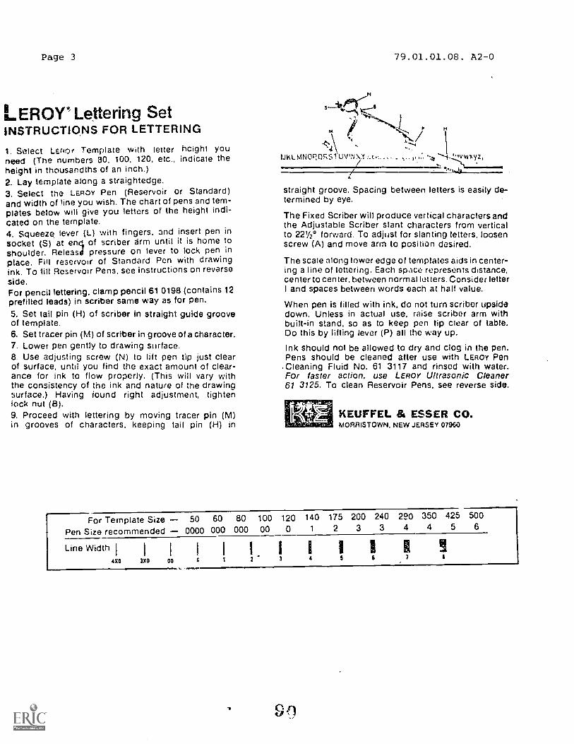
Page 3
LEROY* Lettering SetINSTRUCTIONS FOR LETTERING
1. Select LEnor Template with letter height youneed (The numbers 80. 100. 120, etc., indicate theheight in thousandths of an inch.)2. Lay template along a straightedge.3. Select the LEROY Pen (Reservoir or Standard)and width of line you wish. The chart of pens and tem-plates below will give you letters of the height indi-cated on the template.4. Squeeze lever (L) with fingers, and insert pen insocket (5) at en il of scriber arm until it is home toshoulder. Releasd pressure on lever to lock pen inplace. Fill reservoir of Standard Pen with drawingink. To MI Reservoir Pens, see instructions on reverseside.For pencil lettering, clamp pencil 61 0198 (contains 12prefilled leads) in scriber same way as for pen.5. Set tail pin (H) of scriber in straight guide grooveof template.6. Set tracer pin (NI) of scriber in groove of a character.7. Lower pen gently to drawing surface.8. Use adjusting screw (N) to lift pen tip just clearof surface, until you find the exact amount of clear-ance for ink to flow properly. (This will vary withthe consistency of the ink and nature of the drawingsurface.) Having found right adjustment, tightenlock nut (B).9. Proceed with lettering by moving tracer pin (M)in grooves of characters, keeping tail pin (H) in
79.01.01.08. A2-0
5-32terl<6
M P
HNN/.1\
IALMNOP,QRS l'UVW LC0.. t 'evwxyz,
A
straight groove. Spacing between letters is easily de-termined by eye.
The Fixed Scriber will produce vertical characters andthe Adjustable Scriber slant characters from verticalto 221/2° forward. To adjust for slanting letters, loosenscrew (A) and move arm to position desired.
The scale along lower edge of templates aids in center-ing a line of lettering. Each space represents distance,center to center, between normal letters. Consider letterI and spaces between words each at half value.
When pen is filled with ink, do not turn scriber upsidedown. Unless in actual use, raise scriber arm withbuilt-in stand, so as to keep pen tip clear of table.Do this by lifting lever (P) all the way up.
Ink should not be allowed to dry and clog in the pen.Pens should be cleaned after use with LEROY PenCleaning Fluid No. 61 3117 and rinsed with water.For faster action. use LEROY Ultrasonic Cleaner61 3125. To clean Reservoir Pens, see reverse side.
REUFFEL & ESSER CO.MORRISTOWN. NEW JERSEY 07960
For Template Size 50 60 80 100 120 140 175 200 240 220 350 425 500
Pen Size recommended 0000 000 000 00 0 1 2 3 3 4 4 5 6
Line Width4X0 3X0 00
II7

Student: Ale Code: 79.01.01.08.A2-2
Date: Date Published: 10/7/77
Education &onomlc Development 7.M
illas;ow AFL
v473%% 692
program Inc.
WN%-- LAP TEST: INKING TECHNIQUES
PART I R.ULING PEN:
1. When drawing i,.k lines, the ruling pen should be:
a. at an angle of 45 degrees to the paper in the direction of the line.b. at an angle of 60 degrees to the paper in the direction of the line.c. at an angle of 90 degrees to the paper in the direction of the line.d. at any angle that is comfortable.
2. Thicker ink lines arc caused by several factors; which one below does not cause thick lines?
a. slow pen movement.b. caked ink and a dirty pen.c. excess ink in the pen.d. narrow nibs width.
3. When inking, the proper order is:
a. horizontal, curved, vertical & inclined.b. no spec'al order.c. inclined, vertical, horizontal & curved.d. curved, horizontal, vertical & inclined.
4. When tracing a pencil line with ink, the proper method is:
a. to place the pen nibs 1/8 from the line.b. to center the ink line over the pencil line.c. to nave the ink line on the outside of the pencil line.d. to nave the ink line on the inside of the pencil line.
5. Thin ink lines are caused by:
a. all the below.b. rapid movement of the pen.c. hard working surface.d. sharp nibs.
91

Page 2 79.01.01.08.A2-2
PART II AUTOMATIC RESERVOIR PEN:
6. The automatic reservoir pen has how many parts:
a. 3b. 5
c. 6
d. 7
7. What size automatic reservoir pen is used for visibl° object lines:
a. No. 00b. No. 0c. No. 1d. No. 2
8. When inking straight lines with an automatic reservoir pen, the proper order is:
a. vertical, horizontal, inclined.b. horizontal, vertical, inclined.c. vertical, inclined, horizontal.d. inclined, vertical, horizontal.
9. When drawing lines, the automatic reservoir pen should be held:
a. at 60 degrees from direction of travel.b. vertical to paper and 90 degrees from direction of travel.
c. 60 degrees from paper and direction of travel.d. at 60 degrees from paper and 45 degrees from direction of travel.
10. When ink is used in in instrument, it should be:
a. cleaned out frequently.b. ,llowed to dry before cleaning.c. cleaned out just before using.d. cleaned out with sandpaper.

LAP TEST ANSWER KEY: INKING TECHNIQUES
PART I 1. B2. D3. D4. B
5. APART II 6. D
7. C8. B
9. B
10. A
79.01.01.08.A2-2

Mountain-Plain. F.clueatton QsVA:ono/Me Development
PratteAm. Inc.
(11asenty API!. Montana 69231
Fite Code' 79.01.01.09. A1-0
Date Published
Learnin ctivity
PERFORMANCE ACTIVITY- PRECEDENCE OF LINES
Student:
10/7/77
ackage
Date:
OBJECTIVE:
identify the precedence of lines when one or more lines cover each other.
EVALUATION PROCEDURE:
Successful completion of this LAP is determined by correctly answering 8 outof 10 inns on a multiple-choice test that is combined with "Applying BasicMechanical Drawing Techniques" LAP test and is taken after completing that LAP.
RESOURCES:
Technical Drawing, Para. 5.31, pg. 14 .
Basic Technical Drawin;, para. 6.16, pg. 95.
PROCEDURE:
1. Read the above resn...7ce(s).
2. Read the following summary:
a. A visible line always covers up a:
(1) center line(2) hidder line
b. Hidc:?.n 1H.!: cover up:
(1) center lines
P7,6 c c? c. of Kees
NOTE: Visible lines covering center lines andhidden lines are shown at A and B, and ahidden line covering a center line at A and
C. Visible or hidden lines covering centerlines should extend approximately 1/4" out-side the feature for which they are drawn.
Principal Author(s): Charles DvorakJere WheatleySheila Vosen

FamilyEducationPr rnm Learnin
Filo Coder7.Y.01.01.10:A2 0
10-7-77Date Publishod:
Revised: 8-14-79
gdvity ckage%Idol. 1:
Date.
PERFORMANCE ACT1VfiTY: A lying Basic Mechanical Drawing Techniques
OBJECTIVE:
Line weight, line type and measurement are applied to drawing problems using appro-
priate drawing equipment in lead and ink.
EVALUATION PROCEDURE:
Drawing skills are evaluated on the unit performance test.
Successfully complete at least 80% of the items on a multiple-choice test about this
LAP.
RESOURCES.
Basic Technical Drawing, Chapter 3, para. 3.13-3.16, page 28-30.
Technical Drawing, Chapter 2, pp, 46-50, 2.52-2.54.
Drafting Rules and Principles, Chapter 2, pp. 18-28, Fig. 6.
Basic drafting tools: (see Unit LEG)
Basic drafting furniture: (see Unit LEG)
PROCEDURE:
1. Read the above Resources.2. Use Size "A" drawing paper for all of the drawings in this LAP.
3. Draw an 81/2 by 11 rectangle on 3 sheets of paper, using construction lines inside
this rectangle. D'.-aw a 1/4" border and 1/2" title block as shown in Layout A-2 on
the back irlide cover of the Tecnnical Drawing book.
NOTE: Keeping_ Your Drawing Clean. Graphite filings from your lead and lines
drawn on your paper, will work their way into your jrawing surface as
you move your T-square and triangles across the paper. Always remove
filings from newly sharpened lead by wiping the poi. on a cloth or
using the filter it your lead pointer. Periodical ly clean both sides
of your T-square and triangles with a soft cloth. You may use a mild
cleaning product. Sprinkling small amounts of erasure powder on your
drawing will causf:. the T-,square to roll the particles over the paper, thus
col ectihg loose graphite. Dry, clean pads may be used to rub over drawing
periodically, in order to collect graphite and remove light smudges. If
you still have trouble with smearing. check your hands and make sure they
are clean. You may want to place a clean sheet of paper over the parts of
your drawing where you rest you- hand or slide your T-square. Do not use
your nand to brush awaj yolir erasure crumbs. Use your drafting brush.
Principal Author(s): C. Wetterling, S. Vosen, J. Wheatley5
1+etztarthr rilleistivahad timatio 1S

Page 2
PROCEDURE (continued)
4. Follow the directions for each exercise shown below:
A.
J411,..41.
reP
45° AXik
Ili 1
)_
ii
7P
omrmmewmr.mmnow.mmelmommovormawwwwwasamemeca.
4
79.01.01.10:A2-0
111117........5 6
3
1) After you have drawn your border and title block, determine your drawingspace -- vertical and horizontal.
2) Divide this space into 6 equal rectangles. Use #2H lead to darken allvisible lines.
RECTANGLE 1:
Use your bow diOdc-s to divide the space into 8 equal horizontal spaces. Referto the pror-ue. described it :our text book.
RECTANGLE 2:
Use your architect scale to mark off 1/24 vertical spaces, starting from the leftside of the rectangle. Refer to 3.23 and Fig. 3-29, p. 36-37, Basic TechnicalDrawing. Note the correct method for taking measurements from your scale.
RECTANGLE 3:
Find the center of the rectangle (thaw diagonas from corner to corner, the inter-secting point is the middle). Draw a line at 45° through the center. Construct alight perpendicular to this line. Mark off points spaced 1/4" a part along theconstruction line, starting at the center. Draw visible lines through these pointsand parallel to the first visible line drawn.
RECTANGLE 4:
Follow same procedures for rectangle 3. Obtain a 75° angle by positioning your twotriangles. Spa..e visible lines 1/2" apArt, starting at the center.
V(3
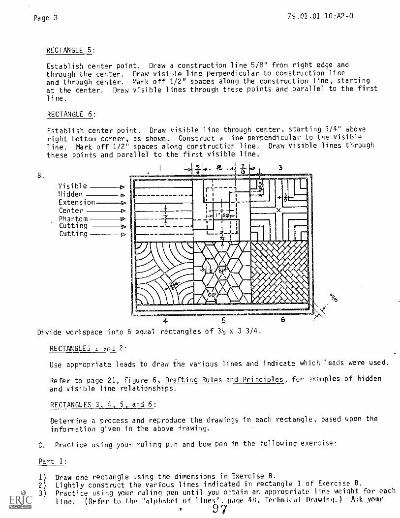
Page 3
B.
RECTANGLE 5:
79.01.01.10:A2-0
Establish center point. Draw a construction line 5/8" from right edge and
through the center. Draw visible line perpendicular to construction line
and through center. Mark off 1/2" spaces along the construction line, starting
at the center. Draw visible lines through these points and parallel to the first
line.
RECTANGLE 6:
Establish center point. Draw visible line through center, starting 3/4" above
right bottom corner, as shown. Construct a line perpendicular to the visible
line. Mark off 1/2" spaces along construction line. Draw visible lines through
these points and parallel to the first visible line.
VisibleHiddenExtension 4>
CenterPhantomCuttingCutting
3
4 5
Divide workspace into 6 equal rectangles of 32 x 3 3/4.
RECTANGLE.; 1 and 2:
Use appropriate leads to draw the various lines and indicate which leads were used.
Refer to page 21, Figure 6, Drafting Rules and Principles, for .examples of hidden
and visible line relationships.
RECTANGLES 3, 4, 5, and 6:
Determine a process and reproduce the drawings in each rectangle, based upon the
information given in the above Irawing.
C. Practice using your ruling p.n and bow pen in the following exercise:
Part I:
1) Draw one rectangle using the dimensions in Exercise B.
2) Lightly construct the various lines indicated in rectangle 1 of Exercise B.
3) Practice using your ruling pen until you obtain an appropriate line weight for each
line. (Refer to the "alphabet of lines", page 48, Technical Drawing.) /VA your
97

Page 4 79.01.01.10:A2-0
4) Ink over the construction lines, remembering to center the ink line over the
lead line. (Refer to Figure 2.70, Technical Drawing.)
Part II:
1) On the same paper, construct a 6" x 4" rectangle.
2) Find the center point.3) Use your compass to lightly construct a 7/8" diameter circle from this center
point. Use 4-H or lead in your compass. You may sharpen your compass lead
by placing it in your lead holder and using your lead pointer.
4) Construct a circle with a 1/4" radius, concentric to the first circle.
5) Measure in 5/16" from the right on the bottom horizontal line. Connect this
point to the upper right hand corner with a light construction line.
6) Ink all lines using your ruling pen and bow compass. (Refer to 2.54, pp. 46-48,
Technical Drawing.)
REMEMBER: Ink circles and arcs first.Ink horizontal lines next.Ink vertical lines next, and,Ink inclined lines next.
D. You do not need to center ordraw a border for the follow-ing object.
3-3-
3Drill
__--
90°
(50°
13ih DRILL
Drill2
78
AB= 3
BC= I Al-
E)= 1 g
DE =2
EF -dig
F(.; =
H = I
J = 3
_ 3K - 2 5-2
k
Use triangles to arrive at the specified angles, as described on page 29, Basic Tech-
nical Drawing. DO NOT USE THE PROTRACTOR!
NOTE: Your drawing may not look exactly like the drawing in this LAP. Omit the
dimensions and notes on your drawing.
1) When the drawings and answers to questions for Exercises A, B, C, and D meet your
instructor's satisfaction, take the LAP test.
2) The performance test is located in the Performance Criterion File.
00u
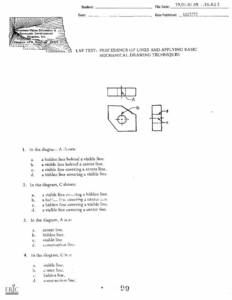
ountain-Plains EducationSo-'''"..°- , onomic Development
/ Glasgow AFB.
Inc.. .
. '57cinCtina 59231--..,-.....,---...
1 la ' .-St.N, I z"Z--...,-C*----:----:-----
1. In the diagrari:, A shows:
Student: File Code:79.01.01.09. - .10.A2.2
Date: Date Published: 1017/77
LAP TEST: PRECEDENCE OF LINES AND APPLYING BASICMECHANICAL DRAWING TECHNIQUES
a. a hidden line behind a visible line.b. a visible line behind a center line.c. a visible line covering a center line.d. a hidden line covering a visible line.
2. In the diagram, C shows:
a. a visible line co,,ring a hidden line.b. a linc covering a centerc. a hidden line covering a visible line.d. a visible line covering a center line.
3. In the diagram, A is a:
a. center line.b. hidden line.c. visible lined. construction line.
4. In the diagram, C is a:
a. visible line.b. c'miter line.c. hiddend. construction link..
9
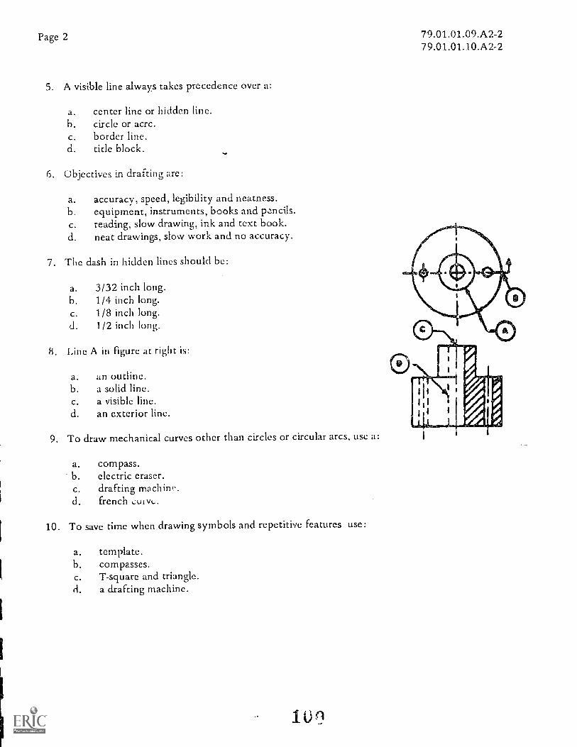
Page 2
5. A visible line always takes precedence over a:
a. center line or hidden line.b. circle or acrc.c. border line.d. title block.
6. Objectives in drafting are:
a. accuracy, speed, legibility and neatness.b. equipment, instruments, books and pencils.c. reading, slow drawing, ink and text book.d. neat drawings, slow work and no accuracy.
7. The dash in hidden lines should be:
a. 3/32 inch long.b. 1/4 inch long.c. 1/8 inch long.d. 1/2 inch long.
8. Line A in figure at right is:
a. an outline.b. a solid line.c. a visible line.d. an exterior line.
9. To draw mechanical curves other than circles or circular arcs, use a:
a. compass.b. electric eraser.c. drafting machine.d. french
10. To save time when drawing symbols and repetitive features use:
a. template.b. compasses.c. T-square and triangle.d. a drafting machine.
10
79.01.01.09.A2-279.01.01.10.A2-2

79.01.01.09.A2-279.01.01.10.A2-2
LAP TEST ANSWER KEY: PRECEDENCE OF LINES AND APPLYINGBASIC MECHANICAL DRAWING TECHNIQUES
LAP
09 1. C2. B
3. C4. C5. A
10 6 A7. C8. C9. D
10. A
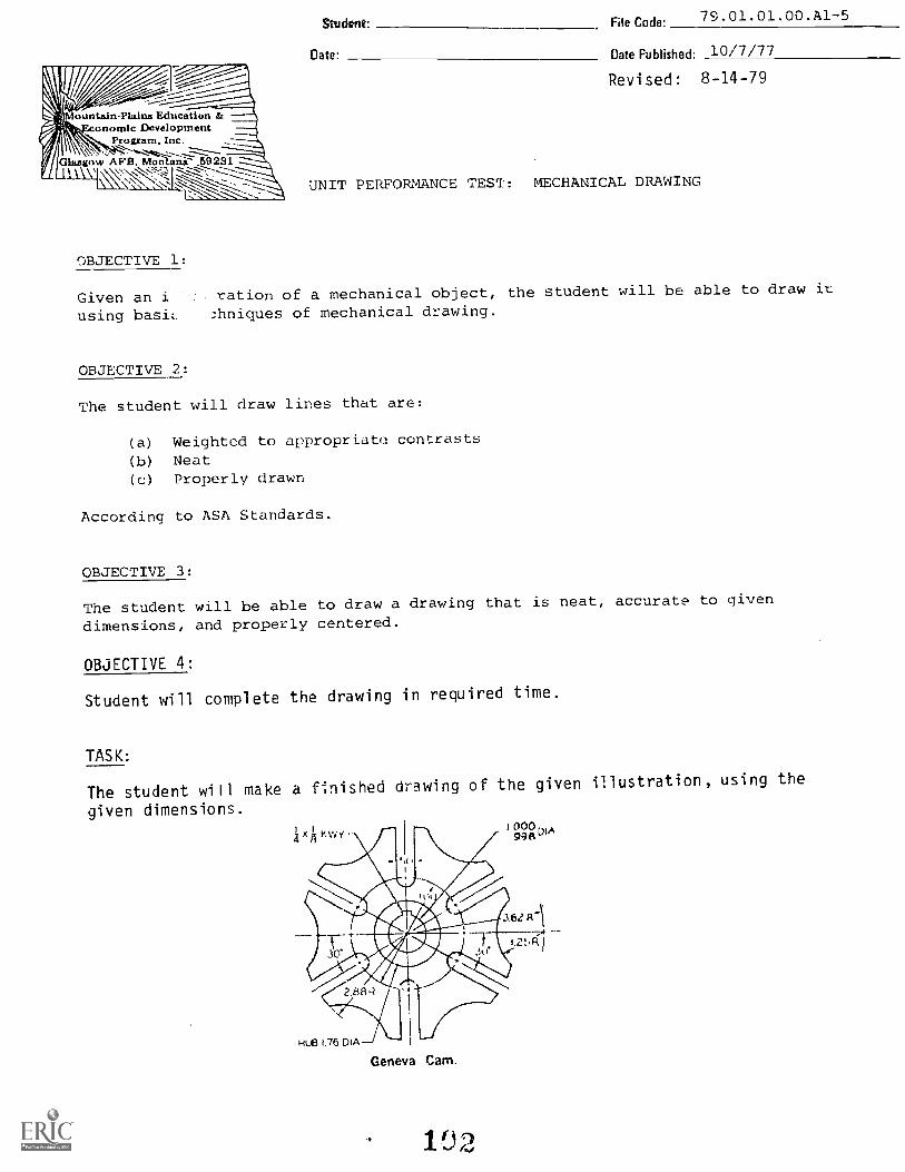
ountainPlairs Education &anomic Development
Program, Inc.-
Glasgow AFB, Morilanii 69231%.\\I
-1\
OBJECTIVE 1:
Given an iusing basic_
OBJECTIVE 2:
Student: File Code:79.01.01.00.A1-5
Date. Date Published: 10/7/77
Revised: 8-14-79
UNIT PERFORMANCE TESq: MECHANICAL DRAWING
ration of a mechanical object, the student will be able to draw it
3hniques of mechanical drawing.
The student will draw lines that are:
(a) Weighted to appropriate contrasts
(b) Neat(c) Properly drawn
According to ASA Standards.
OBJECTIVE 3:
The student will be able to draw a drawing that is neat, accurate to given
dimensions, and properly centered.
OBJECTIVE 4:
Student will complete the drawing in required time.
TASK:
The student will make a finished drawing of the given illustration, using the
given dimensions.

Page 2 79.01.01.00:A1-5
ASSIGNMENT:
1. Use size A paper.2. Center object on paper. No border needed. Do not letter the dimensions.
3. Use proper lead and line weights for visible and center lines.4. When drawing is completed and evaluated, take the Unit Test.
CONDITIONS:
The drawing is to be completed in a typical drafting room setting, using the Resourceslisted.
The student will not be able to use the instructor(s) or other students as a resource.
RESOURCES:
Drawing set30 x 60 triang-'.e.
45 x 45 triangle.Architect's scaleEngineer scaleBrushLead holderLead pointerErasing shieldDrafting tableDrafting board"T" squareStool
EraserLeads (2H and 6H)TapeDrawing paperElectric EraserProtractorTechnical Drawing, Giesecke/Mitchell/Spencer/HillMechanical Drawing, French and SvensonEngineering Drawing and Graphic Technology, French and Vierck
103

Page 3
ountain-Plains Education &-.)nomic Development
Program. inc...
IGlaarow A FB, Mon nit- 59231
PERFORMANCE CHECKLIST:
79.01.01.00. A1-5Student File Code:
Date Date Published- 10/7/77
OVERALL PERFORMANCE: Satisfactory Unsatisfactory
Revised: 8-15-7R
CRITERIONMet Not Met
Objective 1:
1. Uses basic techniques.
Criterion: No lines are missing from the drawing.
Objective 2:
2. Visible lines are neat and properly drawn
Criterion: (ASA Standards) , Technical Drawiny, p. 20.
1
3. Center lines are neat and properly drawn.
Criterion: (ASA Sta!-Idards), Technical Drawing, p. 20.
4. Visible lines are of appropriate contrast in relation.
to the other lines.
Criterion: (ASA Standards), Technical Drawing, p. 20.
5. Center lines are of appropriate contrast in relation
to the other lines.
Criterion: (ASA Standards), Technical Drawing, p. 20.
104
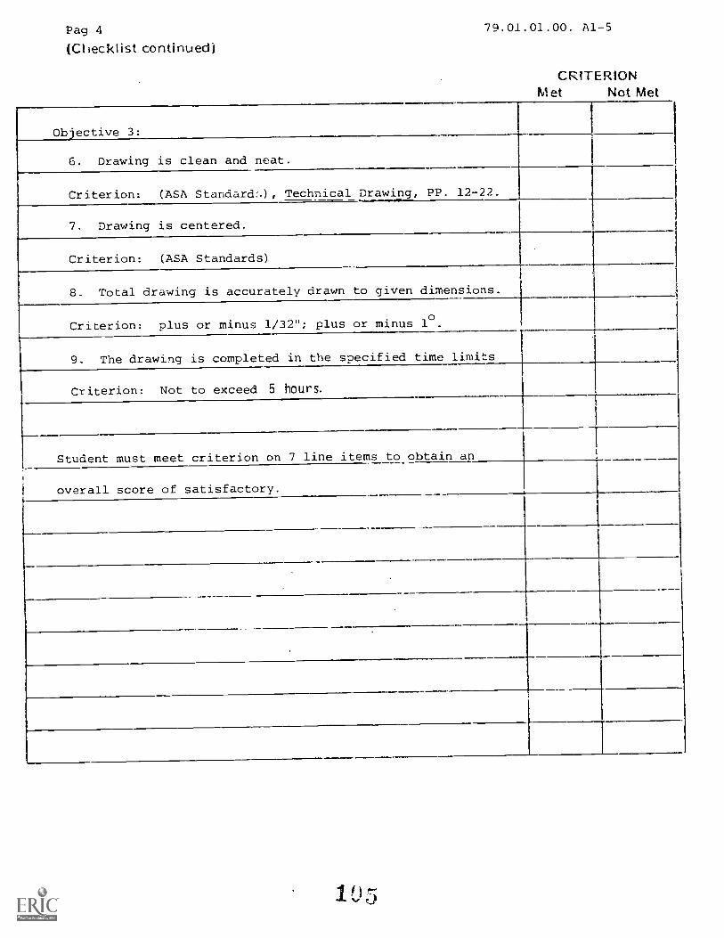
Pag 4
(Checklist continued)79.01.01.00. A1-5
CRITERIONMet Not Met
Objective 3:
6. Drawing is clean and neat.
Criterion: (ASA Standard:.), Technical Drawing, PP. 12-22.
7. Drawing is centered.
Criterion: (ASA Standards)
8. Total drawing is accurately drawn to given dimensions.
Criterion: plus or minus 1/32"; plus or minus 10.
9. The drawing is completed in the specified time limits
Criterion: Not to exceed 5 hours.1----
Student must meet criterion on 7 line items to obtain an
overall score of satisfactory.
1
.
.

"tyountain- Plains Education &
onomtc Deve! optnentProgram, loc.
Glaeg-3w AFB, Mon na 59231
79.01.01.01
1. Soft leads are used:
Student: File Code: 79.01.01.00 .B2-2
Date: Date Published: 6-18-74
Revised: 12-03-79
UNIT FOST T,ST: MECHANICAL DRAWING
a. whea extreme accuracy is required and for basic construction lines.
b. only on soft paper.c. for art work but not for mechanical drawing.
d. for general purpose work in mechanical drawing.
2. In our course, it is suggested you use which lead for object lines:
a. Hb. 2H
c. 4H
d. 6H
3. Lead weight, (hardness), is determined by:
a. the color of lead.
b. the size of lead.c. the amount of graphite in lead.
d. the weight in ounces.
4. All lead is the same darkness, differences in line contrast are caused by:
a. varying line width.b. pencil pressure.c. lead darkness.d. the type of line.
5. Construction lines should be made:
a- thin, but light.b. wide, but dark.c. wide, but light.d. thin, but dark.
79.01.01.02
6. Left-handers should place the head of the T-square:
a. on the right-hand side of the drawing board.
b. on the bottom edge of the drawing board.
C. on the .left -hand !;ids of the drawing board.
d. on the Lop edge of the drawing board.

Page 2 79.01.01.00.82-2
79.01.01.02 (continued)
7. When attaching paper to the drawing board, use:
a. two fasteners.b. four fasteners.c. as many fasteners as you need.d. six fasteners.
8. Cellophane tape is:
a. hard to remove and not recommended as a fastener.b. easy to remove from the paper.c. damaging to the board surface.d. the best fastener to use.
9. When mounting paper to the board, align the straightest edge of the paper to the:
a. left edge of the board.b. top edge of the T-square.c. right edge of the triangle.d. bottom edge of the T-square.
10. The corner of the paper to attach to the board first is the (for right-handedpeople):
a. bottom right.b. top right.c. bottom left.d. top left.
79.01.01.03
11. A horizontal line is drawn:
a. from left to right if you are right handed.b. from right left if you are right handed.c. frm, to right if v(_.;1 are left handed.
E. from left to right or right to left.
12. Horizontal lines are drawn:
a. along the top of the T-square.b. along the bottom of the T-square.c. along the right of the T-square.d. along the left of the T-square.
13. A horizontal line drawn at the top of the paper should be to ahorizontal line at the bottom of the paper.
a. vertical.b. parallel.c. perpendicular.d. at an angle.
107

Page 379.01.01.00.132-2
79.01.01.03 (continued)
14. The type of line drawn along the top of the T-square is:
a. horizontal.b. vertical.c. curved..d. circles and arcs.
15. The T-square is held tight- the board and the paper when:
a. lettering freehanded.b. drawing circles and arcs.c. drawing with the french curve.d. drawing horizontal lines.
79.01.01.04
16. Vertical lines are drawn with hhe T-square and thc.:
a. 45 degree triangle only.b. 45 degree or 30 degree x 60 degree triangle.c. 30 degree x 60 degree triangle only.d. french curve.
17. When drawing verticle lines, the head of the T-square is held:
a. on the bottom of the board.b. on the top of the board.c. tightly against the working edge of the board.d. loosely.
18. When drawing vertical lines and the cadge of the triangle is too sharp:
a. throw it away.b. sand the edge lightly with 400 sandpaper.c. L'harpen thud. don't- the line.
19. The triangle is held tightly the T-square, board and paper when:
a. lettering freehanded.b. drawing circles and arcs.c. drawing with the french curve.d. drawing verti-oal lines.
20. When drawing vertical lines, the trail of graphite particles are:
a. left where they fall.b. rubbed into the paper.c. removed by eraser.d. blown of at intervals.

Page 4
79.01.01.05
21. In the diagram, distance 0 to B is:
a. 1"
b. 10"
c. 1 1/16"d. 11/2"
22. In the diagram, distance A is:
OD-4-(0-1+6,01a. 1.4"
b. 5/8 metersc. 14'
d. .7"
79.01.01.0C.B2-2
10IITTII111111111{Iii0
23. In the diagram, distance C is: 1"=20'
a. 111'
b. 3/7"c. 6'
d. 1/4 meters
24. In the diagram, distance B plus distance C is:
a. 1.6"
b. .8 metersc. .8"
d. 16'
25. Given an engineers scale, using the 50 scale, each increment is:
a. 1/5 of an inch.b. .5 of an inch.c. 1/50 of an inch.a. one inch.
79.01.01.06
26. When centering a two view drawing:
a. distance B always equals distance C.b. distance B always equals distance G.c. distance B is always equal to distance A.d. distance B can be any length you decide.
27. The formula for vertical spacing is:
a. A plus B divided by 2.b. A plus B divided by 3.c. H minus (J plus G) divided by 2.d. H minus (J plus G) divided by 3.
103
4-- A
FITF-7

Page 5 79.01.01.00.62-2
79.01.01.06 (continued)
28. When drawing a two-view drawing, the first step is to:
a. determine the spacing between the views.b. draw horizontal construction lines.c. draw vertical construction lines.d. draw circles and arcs.
29. On the two-view drawing, if 1=16" and F=6", what is -.he space on each side of
t..e object:
a. 8"
b. 311"
c. 10"
d. 5"
30. On the two-view drawing, if H=84" and the height of the ol.)ject was l'.1" and the
depth of the object was 1", what would D equal?
a. 2"
b. 6"
c. 4"
d. 2 3/4"
79.01.01.07
31. When centering a three-view drawing:
a. distance A equals distance C and distance F.b. distance A, B, and C are never equal.c. distance A equals distance B and distance F.d. distance E equals distance B.
32. When centering a three-view drawing:
a. distance ;! d I"; are always equal.b. :J and are alw-7s equal.c. distances and arc always equal.d. disLances A, V, and C are always equal.
33. The formula for vortical spacing is:
a. J minus (C1 plus P plus H) dividod by 2
h. A plus 13 plus C divided by A.c. A plus B plus C divided by 2.d. J minus (G plus K) divided by 2.
34. The formula for horizontal spacing is:
a. A plus i3 plus C divided by 3.b. I minus (2 times K) divided by 3.c. A plus P plus C divided by 2.d. I minus (K plus H plus B) divided by 2.
110
06'A)1
I
irupH
F
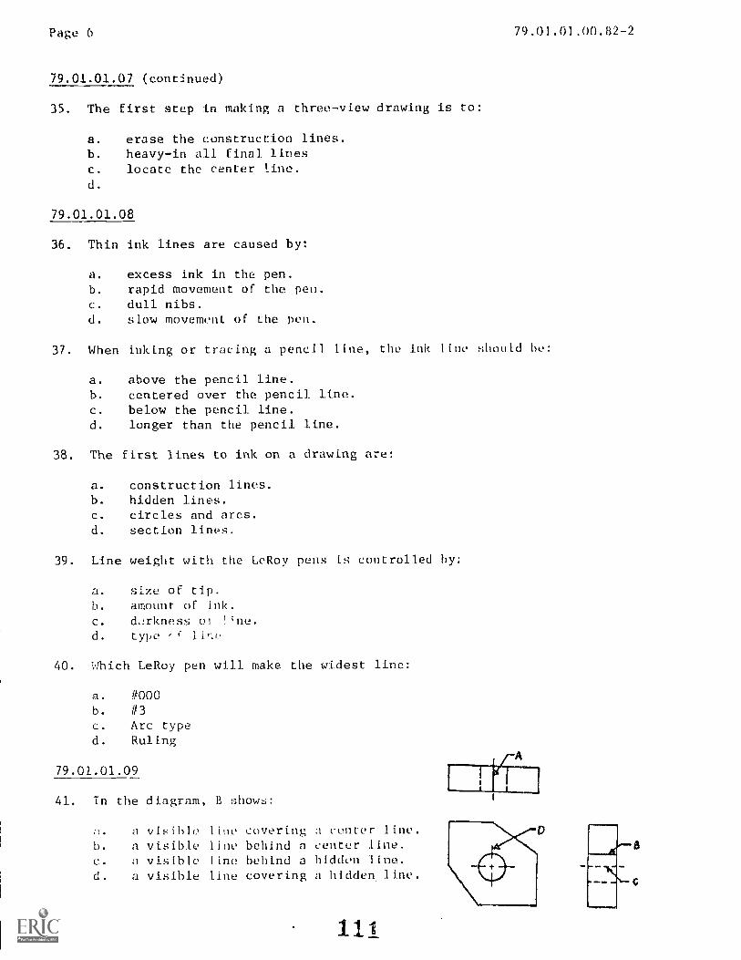
Page 6 79.01.01.00. B2 -2
79.01.01.07 (continued)
35. The first step in making a three-view drawing is to:
a. erase the construction lines.b. heavy-in all final linesc. locate the center line.d.
79.01.01.08
36. Thin ink lines are caused by:
a. excess ink in the pen.b. rapid movement of the pen.c. dull nibs.d. slow movement of the pen.
37. When inking or tracing a pencil line, the ink line should he:
a. above the pencil line.b. centered over the pencil line.c. below the pencil line.d. longer than the pencil line.
38. The first lines to ink on a drawing are:
a. construction lines.b. hidden lines.c. circles and arcs.d. section lines.
39. Line weight with the LeRoy pens is controlled by:
a. size of tip.b. amount of ink.c. darkness of Hne.d. type
40. Which LeRoy pen will make the widest line:
a. #000b. #3c. Arc typed. Ruling
79.01.01.09
41. In the diagram, B shows:
a visible line covering a center line.b. a visible line behind a center line.c. a visible line behind a hidden line.d. a visible line covering a hidden line.
111

Page 7
79.01.01.09 (continued)
4./.. In Iho diagram, A II; a:
a. center line.b. hidden line.c. visible line.d. construction line.
43. In the diagram, D is a:
a. visible line.b. hidden line.c. construction line.d. center line.
44. In the diagram, B is a:
a. center line.b. hidden line.c. visible line.d. construction line.
79.01.01.00.B2-2
45. A hidden line always takes precedence over a:
a. circle or arc.b. visible line.c. center line.d. border line.
79.01.01.10
46. Objectives in drafting are:
a. accuracy, speed, legibility and neatness.b. equipment, instruments, books, and pencils.
c. reading, slow drawing, ink, and text books.d. dr2wings, slow work. and no accuracy.
47. A pencil drawing, not for reproduction, is made on:
a. polyester film.b. tracing cloth.c. tracing paper.d. drawing or detail paper.
48. To replace the T-square, triangles, scales, and protractor use a:
a. parallel-ruling straightedge.b. Letup] ate.
. drartfiw, machine.
d. myIar sheet..

Page 8 79.01.01.00.B2-2
79.01.01.10 (continued)
49. TO draw mechanical curves other than circles or circular arcs, use a:
a. compass.
b. electric eraser.c. drafting machine.
d. french curve.
50. For quick, repetitive work, use a(n):
a. template
b. scale
c. scriberd. printer
1 3

79.01.01.00.B2-2
UNIT POST TEST ANSWER KEY:
Date Revised: 12-03-79
MECHANICAL DRAWING
LAP 01: 1. C
2. BLAP 09: 41. D
3. C42. C
4. A43. D
5. A44. C
45. C
LAP 02: 6. A
7. CLAP 10: 46. A
8. A47. D
9. B48. C
10. D49. D
50. A
LAP 03: 11. A12. A13. B
14. A15. D
LAP 04: 16. B
17. C
18. B
19. D
20. D
LAP 05: 21. A
22. C
23. C
24. D
25. C
LAP 06: 26. C
27. D
28. A
29. D
30. A
LAP 07: 31. D
32. C
33. A34. D
35. D
LAP 08: 36. B
37. B
38. C
39. A
40. B
11 A
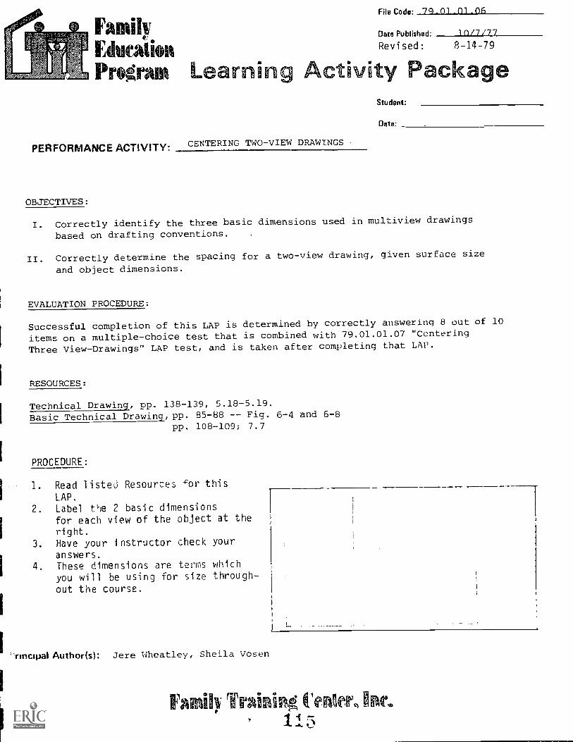
FamilyEducationProgram Learn
File Code. 74.01.01.06
Date Published: 10/7/77
Revised: 8-14-79
Activity PackageStudent:
Date-
PER FORMANCE ACTIVITY.CENTERING TWOVIEW DRAWINGS
OBJECTIVES:
I. Correctly identify the three basic dimensions used in multiview drawings
based on drafting conventions.
II. Correctly determine the spacing for a two-view drawing, given surface size
and object dimensions.
EVALUATION PROCEDURE:
Successful completion of this LAP is determined by correctly answering 8 out of 10
items on a multiple-choice test that is combined with 79.01.01.07 "Centering
Three View-Drawings" LAP test, and is taken after completing that LAP.
RESOURCES:
Technical Drawing, pp. 138-139, 5.18-5.19.Basic Technical Drawing, pp. 85-88 -- Fig. 6-4 and 6-8
pp. 108-109; 7.7
PROCEDURE:
1. Read listed Resources cor this
LAP.
2. Label the 2 basic dimensionsfor each view of the object at theright.
3. Have your instructor check youranswers.
4. These dimensions are terms whichyou will be using for size through-
out the course.
Thrmtpal Author(s): Jere Wheatley, Sheila Vosen
Fainii)/ Training Collet), Inc.II 3

Page 2 79.01.01.06
NOTE: Determine the spacing of the views in relation to the drawing surface measuredfrom the top line of the title block and exclusive of the border.
1. To determine horizontal spacing.a. Subtract the width of the ohject from the hori/ontal width of the
drawing surface. In the example, the object width - 6", and thehorizontal width = 17". Therefore: 17 - 6 = 11.
I
-
L7
C T 1
3"
)
' -I
1 .,
A D 6. B
I.. r.E
f :
b. The remainder (11) must then be divided by 2, since there is spaceon either side of the object, (A and B): 11 4 2 = 5T of space oneach side of the object.
2. To determine vertical spacing:a. Add vertical dimensions of height and depth. The example shows 3"
depth and 1" height: 3 + 1 = 4" total vertical object space.b. Subtract this total from the vertical drawing surface: 914" 4 =
51/4u.
c. The remainder (514) must then be divided by 3, since there are 3 equalempty spaces on the vertical(C = D = E).
3 Work through the example in Stepsprocess and mathematics involved.
4 Do the following problem based onprocedure explained in this LAP.
GIVEN:
surface of the paper: 51/4 i 3 = 1 3/4
1 and 2 until you fully understand theThen go on to the problem in Step 4.
the information given below and the
Drawing surface dimensions: Horizontal = 17"
Vertical = 9 1/4"
Object size dimensions: Width = 9 3/4"
Depth = 3 1/16"
Height = 3 1/2-
PROBLEM:
The horiztonal spacing equals
The vertical spacing equals
Check your answers with the instructor's key.
5. LAP test is combined with LAP .07.
11G

FamilyEducAs fiatProgram Learn in
File Code 79.01.01.07.
Date Published. 1R/7/77
Reyised: 8-14-79
ctivity Package&Wilmot:
PERFORMANCE ACTIVITY: CENTERING THREE-VIEW DRAWINGS
OBJECTIVE:
Dote:
Correctly determine spacing for centering a three-view drawing given surface andobject dimensions.
EVALUATION PROCEDURE:
Successfully complete at least 80% of the items on a multiple-choice test aboutthis LAP.
RESOURCES:
Basic Technical Drawing, 7.9, PP. 109-110.
PROCEDURE:
1. To find horizontal spacing.a. Add totals for horizontal dimensions for which
width (W) and depth (D) would be 6" on theexample shown.
b. Arbitrarily determine spacing between 2 objectviews which is proportional to the object sizeand paper (For example 2").
c. Add this to the W and D of the objects.d. Subtract this to'_:1 from the horizontal surface
dimensicre. D ^ide the remainder by 2, for 2 equal spaces on
the outside left and right margins.
HINT: Choosing an arbitrary space between objects is best determined by a feelfor placing the objects at a distance from each other. Thi distanceshould both look good on the drawing surface, and accommodate dimensionsbetween objects. You will learn to see these proportions with experience.If you have much trouble with determining spacing, sketch a basic blockfor each of the object views, cut these out and arrange them on your drawingsurface until you arrive at a suitable spacing.
rincipal Author(s): Sheila Vosen, Jere Wheatley
rape,/ Training ilenier,117

Page 2 79.01.01.07
2. To determine vertical spacing.a. Add the height and depth dimension to the arbitrarily determined space.b. Subtract this number from the total vertical surface.c. Divide the remainder by 2. This will give the top and bottom margins.
NOTE: This is the procedure you will use to center your drawings using size B(12"x18") paper throughout this drafting course.
3. Problem: Determine the horizontal and vertical spacing for the followingproblem
Drawing surface dimensions:horizontal: 17"vertical 9 1/4"
Object dimensions:height: 1 3/4"width: 3 1/4"depth: 2 1/8"
Arbitrary Spacing =
Vertical spacing =
Horizontal spacing =
4. Check your answers with instructor(s) answer key.
5. Take the LAP test.
1 110

File Code: 79.01.02.00:A2-1
Dote Published:10/17/75
Ethicai* Revised: 8-14-79
Program Eigavuodmo kl[pc;10@fiDo® @ffl§c2@
UNIT: LETTERING
RATIONALE:
In 1935, a standardized form of lettering was adopted by the United States American
Standards Institute. This form of letter (U.S. Standard Letters) has become the
accepted style of lettering for mechanical drafting. Other styles of lettering are
used in other fields. The General Rule to follow is: use whatever style of letter-
ing conforms to the job as long as it is legible and uniform.
PREREQUISITES:
Unit: 79.01.01 -- Mechanical Drawing
OBJECTIVES:
Letter to specifications, freehanded, using U.S. Standard Lettering Style.
Letter to specifications with the Ames Lettering guide using a developed free style..
Letter tn specifications, mechanically, when using the Leroy lettering guide.
RESOURCES:
Printed Materials
Basic Technical Drawing, Spencer and Dygdon, Macmillan Company, New York.
Technical Drawing, Sixth Edition, Gieseoke, Mitchell, Spencer and Hill, Macmillan Co.
Lessons in Lettering, Book 1, Third Edition. French and Turnbull, McGraw-Hill, N.Y.
Supplement on Lettering Styles, developed by Drafting class.
Audio/Visuals
Video Cassette on Ames and Leroy Guide.Drafting Series. 'Letter:!,g", Do,lbleday Media.
Equipment
As given in Course LEG.
Principaikkumhoir(s):Sheila Vosen, Chuck Wetterling, Jere Wheatley
Family Train! r, into

1 Page 279.01.02.00:A2-1
GENERAL INSTRUCTIONS:
This unit consists of three Learning Activity Packages (LAPs). Each LAP will provide
specific information for completion of a learning activity.
The general procedure for this unit is as follows:
1) Read the first assigned LAP.
2) Begin and complete the first assigned LAP.
3) Take and score the LAP test.
4) Turn in the LAP test answer sheet.
5) Determine the reason for any missed items on the LAP test.
6) Proceed to, and complete, the next assigned LAP in the unit.
7) Complete all required LAPs for the unit by following steps 3 through 6.
8) In this unit, there are some LAPs that have tests combined with other LAP tests.
These combined tests are taken after completing the last LAP covered by the test.
9) Take the unit tests as described in the Unit LEG "Evaluation Procedures".
10) Proceed to the next assigned unit.
PERFORMANCE ACTIVITIES:
.01 -- Freehand Lettering (U.S. Standard Style)
.02 -- Ames Lettering Instrument (Developed Free Style)
.03 -- Mechanical Lettering Instruments
EVALUATION PROCEDURE:
1. As the student completes each LAP, he/she will take the LAP test for the LAP.
2. The student takes a multiple-choice unit post test and a unit performance test.
Successful unit completion is an 80% on LAP and Unit Tests and meeting the listed
criteria for the performance test.
FOLLOW-THROUGH:
The skills of lettering attained in this Unit shall be one of the basis for evaluating
future drawings.
Print your name and address neatly on a sheet of paper using guide lines for a height
of 1/8".
Go to the first assigned Learning Activity Package (LAP) listed on your Student Pro-
gress Record (SPR).
12)
1,taLn-Plains Education &onomic Development
Program, Inc.
Glasgow AFB, Mon na 59231
79.01.02.01.
Student: File Code: 79 . 01 .02 .00 . A2-2
Date: Date Published 6/19/74
UNIT PRETEST: LETTERING
1. The American Standards call for:
a. vertical or inclined lettering.b. inclined lettering only.c. vertical lettering only.d. a mixture of vertical and inclined lettering.
2. The general rule for spacing letters within a word is:
a. the distance between letters should be equal.b. the distance between letters should be as large as a zero.c. the area between letters should cover about one-fourth as
much area as the preceding letter.d. the areas between letters should be about equal.
3. Pencil lettering should appear:
a. dense black.b, dull grey.c. with different thicknesses of lines,d. with the same measurement between letters.
4. Lettering on drawings should be undeptined:
a. raverb. when special emphasis is required.c. when it is for a dimension.d. only in the title.
5. Inclined lettering is drawn in strokes that follow the order and direction:
a. that is comfortable for you.b. that is unique for inclined lettering.c. of vertical lettering.d. of all horizontal strokes first, then the vertical.
79.01.02.00. A2-2
79.01.02.02.
6. The Ames lettering instrument is used:
a. with an ink pen.b. with a 60 degree triangle.c. with a T-square.d. with a protractor.
The slanted side of the Ames lettering guide is used for:
a. cleaning a pencil.b. drawing vertical guide lines.c. drawing horizontal guide lines.d. drawing slant guide lines.
79.01.02.03.
8. The Leroy set is used with:
a. the ruling pen.b. standard pen reservoir pen, or "020" pencil.c. the standard mechanical pencil.d. a separate piece of pencil lead.
9. With the Leroy, the guide pin follows:
a. the edge of the T-square.b. grooved letters in a template.c. a 45 degree line.d. a 60 degree line.
10. The L pen is constrJ,_.7:ed of:
a. three pieces.b. one piece.c. two pieces.d. four pieces.

LAP
01
02
03
UNIT PRETEST ANSWER KEY: LETTERING
1. A2. D3. A4. B5. C
6. C7. D
8. B9. B
10. C
3
79.01.02.00. A2-2

Mountain-Plains Education &Economic I.Nvelopment
Program, Inc.
(iluitgow AB, Montana 159231 Learning
79.01.02.01.A2-0File Code:
Date Published12/7/77
Revised: 3-14-79
ctivit P cka i eStudent:
pew
PERFORMANCE ACTIVITY:Freehand Lettering (Using U.S. Standard Style)
OBJECTIVE:
Letter, freehanded, various letters, words and numbers using the accepted U.S.
Standard Style.
EVALUATION PROCEDURE:
Instructor will examine lettering for neatness, spacing accuracy and 1 nework . A
maximum of five errors per assignment sheet will be allowed.
A score of 80% is needed for successful completion of the LAP test.
RESOURCES:
Lessons in Lettering, Book 1.
Basic Technical Drawing, Chapter 4.
Attached assignment sheetsFilmstrip: Lettering
PROCEDURE:
Steps
1. Read the above rasuurce(s. )
2. View the t tlmstri p on "Lettering" and the video cassette.
3. Letter, freehanded, the various letters, words and numbers on ass ignment
sheets. Do all lettering on the assignment sheet in U.S. Standard Style.
4. Turn in completed sheets to instructor for evaluation.
5. Take the LAP test and proceed to the next LAP, upon successful completion
of this material .
Principal Author(s):Q. Fogleman, S. Vosen, J. Wheatley
PAGE 1
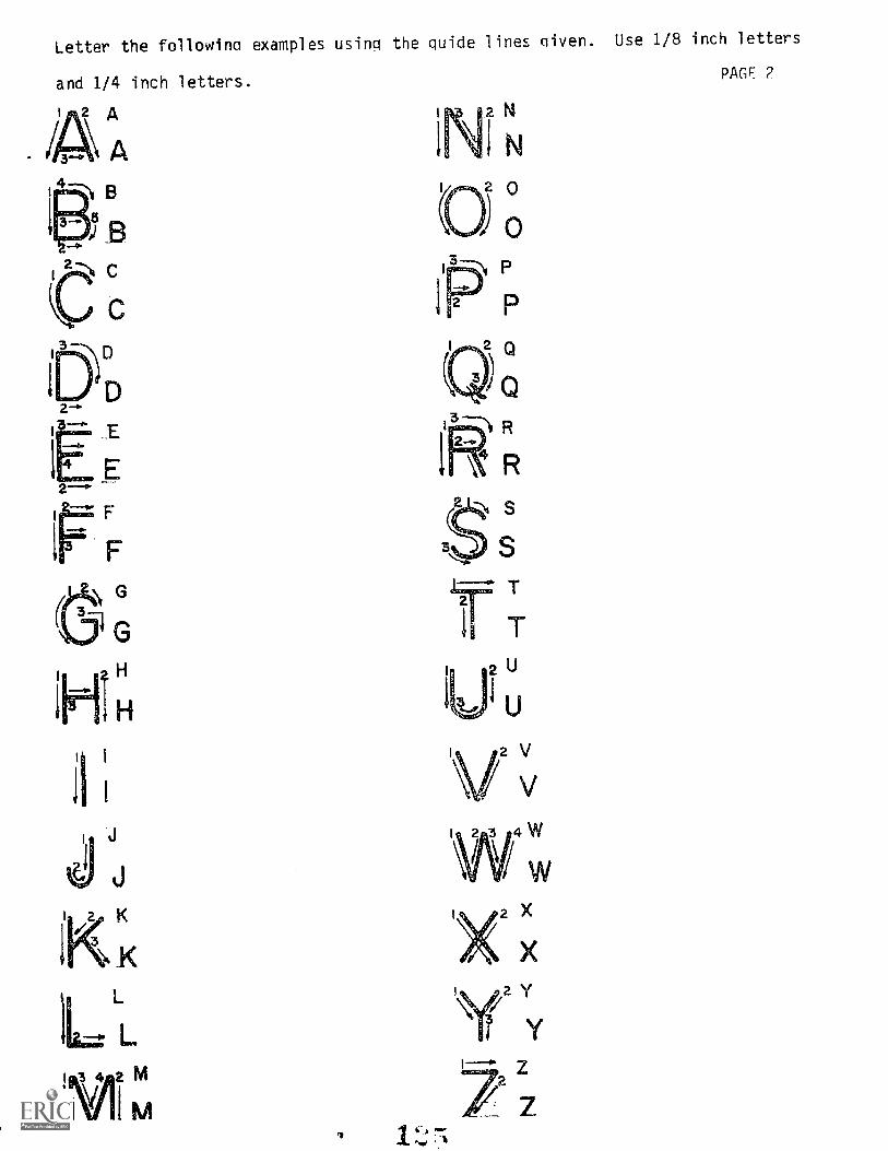
Letter the following examples using the guide lines given. Use 1/8 inch letters
and 1/4 inch letters.PAGE 2
L
3Th R
R
s
ST
11 Tu
Vv
I 2 3 4W
X
I ri yyf
z
Z
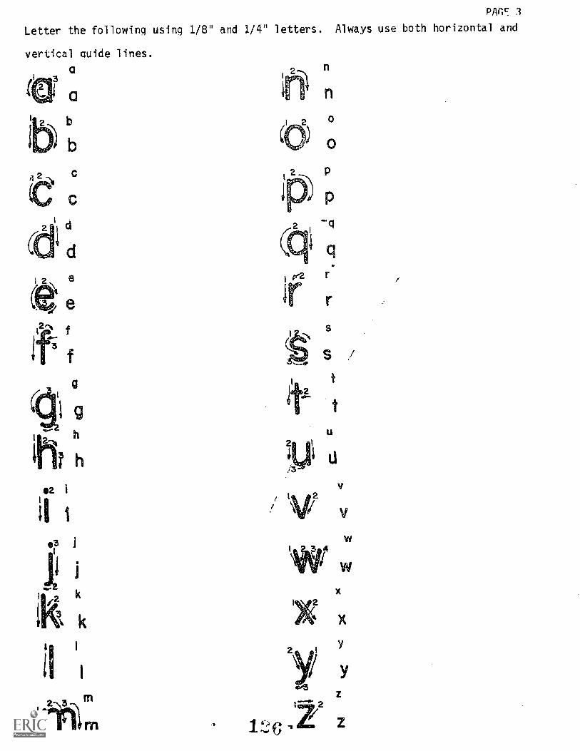
PAn c: 3
Letter the following using 1/8" and 1/4" letters. Always use both horizontal and
vertical guide lines.
a3
ti
n
,rr
r
S
t
t
V
V/2w
3 4
wX
X
2
2

Letter the following sentences using the given guide lines.
GOOD LETTERING IS NOT THEOF AN I N T 1 ENTv BUTVEL ED THRU CO STANT P
1/8 inch
3
1/4 inch
1LETTERS
PAGE. 4
ES LT1
CT CE.
BE CON E :SEA ORLt,tter the above sentence in the spaces below.

PAGE 5
Letter the following in the guide lines provided. Part of the exercise .
is 1/4" lettering and part is 1/8" lettering.
I7_
(9)-3
8 2
,_a16
4
4 8
4 532 S V2 4 zw44" 23.6 cm. 35 in.
32'x 20'= 640 sq. ft.
32,
og7.6 meters

ountain-Plain Education &013,' nate Developmentf PrOaram.Inc.
'GlasgowGlasgow AFB. Mon 59231
1.
Student
Date
LAP TEST: FREEHAND LETTERING
Pencil lettering should be done with:
a. 6H or 8H lead.b. 2B or 4B lead.c. F or H lead.d. any size ink pen.
2. On working drawings, capital letters are usually:
a. 1 meter high.b. 1 inch high.c. 1/2 inch high.d. 1/8 inch high.
3. Americar Standard lettering looks like:
File Code: 79 01 02 01 A2-2
Date Published:6-19-74
Revised: 6-29-78
A) A D AN Dc),9/ei
D FWD
4. The relationship of lower case letters to upper case letters should be:
a. The width plus the height.b. Half the size.c. A ratio of 2 to 7.d. A ratio of 3 to 5.
5. The space between words should be about as large as the letter:
a. U
b. W
c. B
d. 0
6. Pencil lettering should appear:
a. dense black.b. dull grey.c. with different thicknesses of lines.d. with the same measurement between letters.
1 ) 9

Page 2 79.01.02.01.A2-2
7. Lettering on drawings should be underlined:
a. never.b. when special emphasis is required.c. when it is for a dimension.d. only in the title block.
8. Inclined lettering is drawn in strokes that follow the order and direction:
a. that is comfortable for you.b. that is unique for inclined lettering.c. of vertical lettering.d. of all horizontal strokes first, then the vertical.
9. The height of whole numbers should be:
a. 1/2 inch.b. 1/4 inch.c. 1/8 inch.d. 3/4 inch.
10. The height of fractions using 1/8 numbers should be:
a. 3/4 inch.b. 1/8 inch.c. 1/2 inch.d. 1/4 inch.
1 3 n
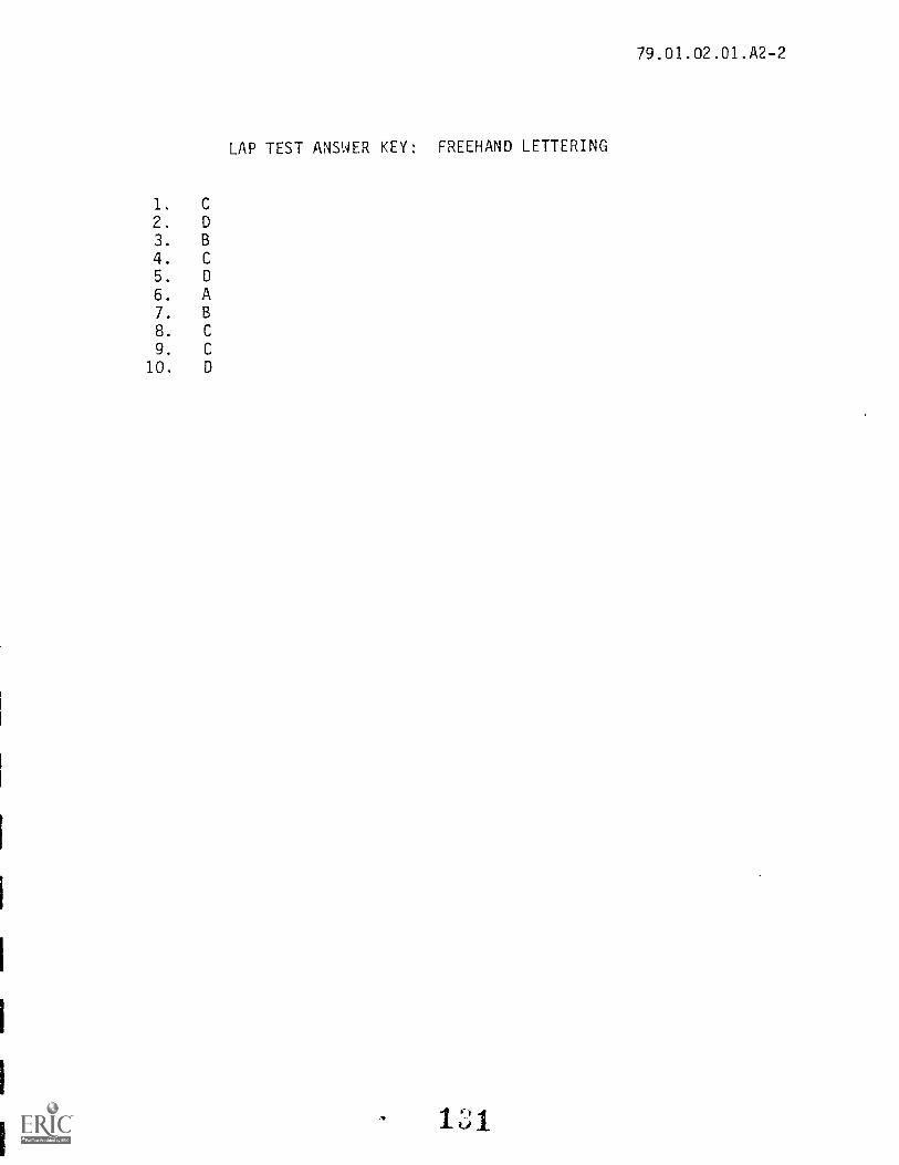
1. C
2. D
3. B
4. C
5. D
6. A7. B
8. C
9. C
10. D
LAP TEST ANSWER KEY: FREEHAND LETTERING
11
79.01.02.01.A2-2

EducationProg rni citivity ge
File Code'79.01.02.02:A2-0
Dote Published:12/7/77
Revised: 8-14-79
PERFORMANCE ACTIVITY:Ames Lettering Instrument
OBJECTIVE:
Correctly use an Ames lettering guide.
EVALUATION PROCEDURE:
Student:
NW:
Instructor will examine work for neatness of lettering and correct usage of the Ames
lettering guide. No more than three errors will be allowed.
Successful completion of this LAP is determined by correctly answering 8 out of 10
items on a multiple-choice test that is combined with "Mechanical Lettering Instru-
ments" LAP test and is taken after completing that LAP.
RESOURCES:
Technical Drawing, page 72 (paragraph 3.17).
Ames Lettering Guide Instruction.
Supplement on Lettering Styles.
Video Cassette on use of Ames Guide.
PROCEDURE:
1. Read the above resource(s). Ask the instructor for a copy of the handout on
lettering styles.
2. Using the ,',wes letterinn guide, letter the entire alphabet in upper case first in
1/4" letters and then in 1/8" letters using your own individual style.
3. Have the work evaluated.
4. Using the Ames lettering guide, letter the entire Evaluation Procedure above
first in 1/4" upper case letters and then 1/8" upper case letters using your
own individual style of lettering.
5. Have the work evaluated.
Principal Author(s): Q. Fogleman, S. Vosen, J. Wheatley
1
siainahl

HOW TO USE THE AMES LETTERING GUIDEWith your Ames Lettering Guide it
is possible to draw guide lines and slopelines for lettering and numbering from1/16 to 2 inches in height.
The numbers on the disc from 10
through 2 denote the height of letters inthirtyseconds of an inch. Assume youwant letters 1/4 inch high. Rotate thedisc so the a is at the frame index. SeeFigure 1.
To turn the disc clockwise, hold the frame at the upper lefthand (-or.ner with the left hand. Rotate the disc with the right hand. To turn thedisc counterclockwise, use the reverse procedure.
Use a 411 or harder drawing pencil sharpened to a conical point. Withyour tee square or straight-edge in the drafting position, place the base ofthe guide, readable side up, against the top edge of the straightedge.RIGHT-HAND COLUMN OF HOLES: In the column of holes marked2/3, the body of the lower case letters will he 2/3 that of the capitalletters. This ratio is the Reinhardt System.
Place the pencil in the second hole from the top. Keep the pencil in aplane that is perpendicular to the paper, but inclined slightly in thedirection that you are drawing lines.
With the pencil, slide the guide to the right keeping the, base incontact with the tee square until you have reached the terminal point,drawing the line lightly. Upon completion of the first line, move thepencil down hole by hole, repeating the procedure and druwing alternately to the left and then to the right.
You now have one set of three guide lines 1/4 inch high. To drawtwo more sets, repeat the procedure using the rest of dm holes in the 2/3column. See the right side of Fig. 1. Note that the dim. sets of dimeholes are grouped by the elliptical lines, not only in the 2/3 column butthe 3/5 as well.DRAWING MORE THAN THREE SETS OF GUIDE LINES: Move the leesquare and guide down until the top hole in the 2/3 column coincide:4with the bottom line of the last set of guide lines drawn before shiftingthe guide. Do not use this top hole. It is there only to give properspacing between lines when the guide must he moved. Now place, thepencil in the second hole and draw lines as before.LEFTIIAND COLUMN OF HOLES: In the 3/5 column, the body oflower ease leit..s will he 3/5 that of capitals. This ratio is usually usedby i**Igineer3. To use tlis ..olumn, proceed identically as above.
SLOPELINES:
tr.
611 degree elope lines
Always remember . . . draw slope lineslightly and use only enough of them tomaintain slope uniformity.
Ple pre
1
vertical elope lines

CENTER COLUMN OF HOLES: The middle /inr in each set of 3guide lines helps in upper-ease hitters such as B. E, F. 11. etc. You still
soon discover the venter rolnimi In he u most versatile set of holes.
with many other uses such as:
CROSS S/CTIONIJNIS r
EPEIEEZEET-- ----;z3_
Figure 3
CROSS-St:mot-41mi: For 1/8" spac-
ing, set the index mark on thedisc (near the 2/3 fraction) at the1/8 mark on the frame for .3/32 oi1/16", set the disc at the corres-ponding marks on the frame. Setthe edge of your straight edge par-allel to the desired lines and proceedas shown in the upper felt -baudcorner of Fig. 3.
NUMBERS AND FRACTIONS: Sec the lower right side of Fig. 3 for size
of fractions in relation to whole numbers.
Form GUIDE LINES: To assist beginning draftsmen with lower-case
letters such as g, j, p, q, and y. it is helpful to use a 4th guile line.
Use the top hole, 2nd, 4th, and 5th holes. See the upper right side of
Fig. 3. If two sets are desired, go to the 7th, 8th, 10th, and bottom
holes.Misc. APPLICATIONS:
Many are possible such as the music staff, etc.
BLOCK LETTERS: Severalexamples are shown at the right side of Fig. 4.
GUIDE LINES UP TO IV1 INCHES IN
flEtcw*: Construct parallel lines
at the desired height, using the
top and bottom holes in the centercolumn. For the 3/5 ratio drop 4spaces to the 5th hole and draw thethird guide line. With 11 holes andthus 10 spaces, this will give the2/S - 3/5 ratio. See the left side ofFig. 4 for an illustration of 11 /4 inch
guide lines. Figure 4
If the 1/3 - 2/3 ratio is desired, use the saute procedure but drop only
3 spaces to the 4th hole for the third guide line.
USES OF 1/8 IYCIT SPACED HOLES UP LEFT-HAND SIDE OF
THE FRAME. This sec of boles has many possibilities such as title
blocks and grid lines in multiples of 1/8 inch; section lining and
dimension line spacing, and spacing from 0 to 2" as well as guide lines
for letters and numbers up to 2 inches.
USES OF SYMBOL ON RIGHT-HAND SIDE OF FRAME: This is
provided for such well-known uses as to indicate surface quality, the
American Standard 60 degree refinish mark, and a short leader & /or
weld symbol.

Mountain-Plains RducationEconomic Development
Program.
l;lusgow A I D II. Montana 59231
- ,
79.01.02.03.A2-0File Code:
Date Published-10/17/75
Revised: 8-14-79
ming Acti ty ag
PERFORMANCE ACTIVITY:Mechanical Lettering Instruments
OBJECTIVE:
Letter in ink using a Leroy lettering instrument.
EVALUATION PROCEDURE:
Student:
Date:
Instructor will examine lettering for neatness, spacing, accuracy and linework. No
errors will be allowed in the lettering.
Successfully complete at least 80% of the items on a multiple-choice test about this
LAP.
RESOURCES:
Technical Drawing, pages 78-80 (paragraph 3.25).
Pamphlet on Leroy EquipmentVideo cassette on use of Leroy Guide.
PROCEDURE:
NOTE: Before beginn-Hy: 1) Make sure the instructor has shown you how to take your
pens ,apars and properly clean them. 2) Have your instructor show you how to
use the ..1,4i,Je for letter spacing and line spacing.
1. Read the resource(s) for use of the Leroy lettering instrument.
2. Letter, in ink, the entire alphabet in upper case and lower case letters and
the numbers. Use a Leroy lettering instrument, guide no. 140-C, pen no. 1.
3. Letter the paragraph above (step 2) in four lines using urger case letters.
KEY POINT: Size of templates is in thousandths of an inch (i.e., 140-C = .14"
in height).4. Have the work evaluated.5. When satisfactory, take the LAP test.
Principal Author(s): C. Wetterling, J. Wheatley, S. Vosen
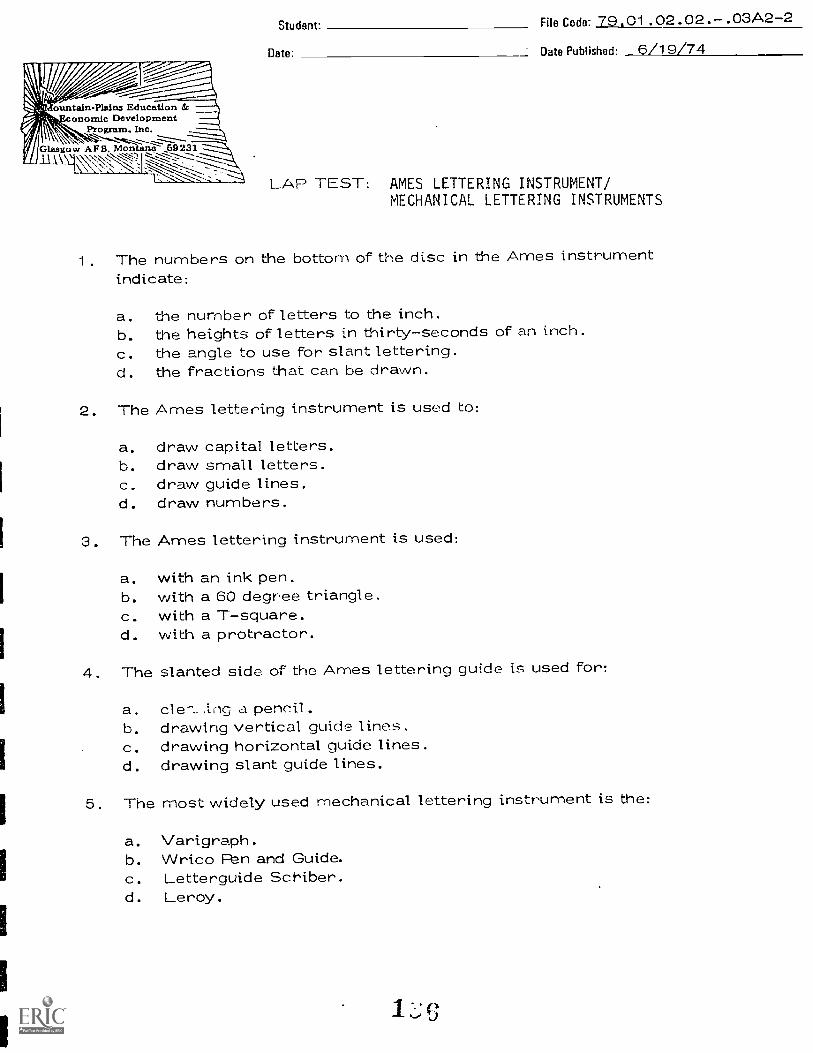
ountain-Plain Education &onomic Development
Program, Inc."s,
Glitagow AFB. Montana 69231
Student. File Code: 79.01.02.02 . . 03A2-2
Date- Date Published: 6/19/74
LAP TEST: AMES LETTERING INSTRUMENT/MECHANICAL LETTERING INSTRUMENTS
1. The numbers on the bottom of the disc in the Ames instrumentindicate:
a. the number of letters to the inch.b. the heights of letters in thirty-seconds of an inch.c. the angle to use for slant lettering.d. the fractions that can be drawn.
2. The Ames lettering instrument is used to:
a. draw capital letters.b. draw small letters.c. draw guide lines.d. draw numbers.
3. The Ames lettering instrument is used:
a. with an ink pen.b. with a 60 degree triangle.c. with a T-square.d. with a protractor.
4. The slanted side of the Ames lettering guide is used for:
a. cle--..,trig a pencil.b. drawing vertical guide lines.c. drawing horizontal guide lines.d. drawing slant guide lines.
5. The most widely used mechanical lettering instrument is the:
a. Varigraph.b. Wrico Fen and Guide.c. Letterguide Scriber.d. Leroy.
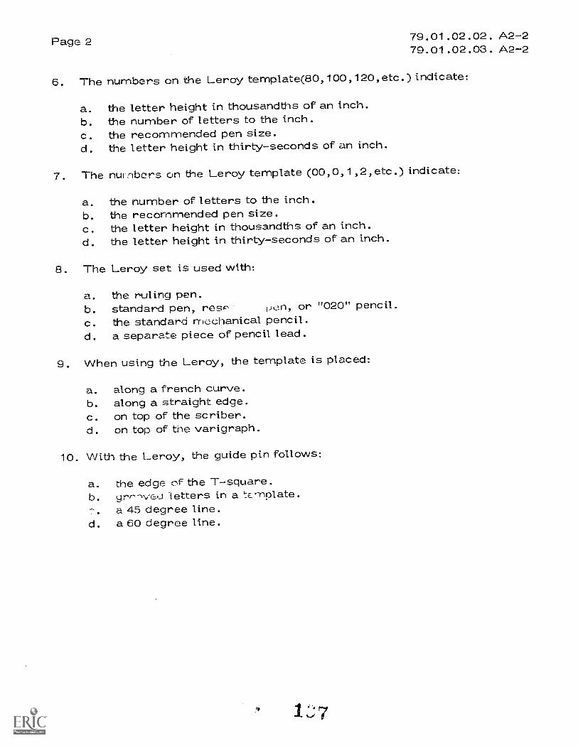
Page 2 79.01.02.02. A2-279.01.02.03. A2-2
6. The numbers on the Leroy template(80, 100,120, etc.) indicate:
a. the letter height in thousandths of an inch.b. the number of letters to the inch.c. the recommended pen size.d. the letter height in thirty-seconds of an inch.
7. The numbers on the Leroy template (00,0,1,2,etc.) indicate:
a. the number of letters to the inch.b. the recommended pen size.c. the letter height in thousandths of an inch.d. the letter height in thirty-seconds of an inch.
8. The Leroy set is used with:
a. the ruling pen.b. standard pen, resP iit n, or "020" pencil.c. the standard mechanical pencil.d. a separate piece of pencil lead.
9. When using the Leroy, the template is placed:
a. along a french curve.b. along a straight edge.c. on top of the scriber.d. on top of the varigraph.
10. With the Leroy, the guide pin follows:
a. the edge of the T-square.b. yrr--1./eo letters in a tc,-nplate.
a 45 degree line.d. a 60 degree line.
LAP
02
03
79.01.02.02. A2-279.01.02.03. A2-2
LAP TEST ANSWER KEY: AMES LETTERING INSTRUMENT/MECHANICAL LETTERING INSTRUMENTS
1. B2. C3. C4. D
5. D6. A7. B8. 13
9. B10. B
1 8
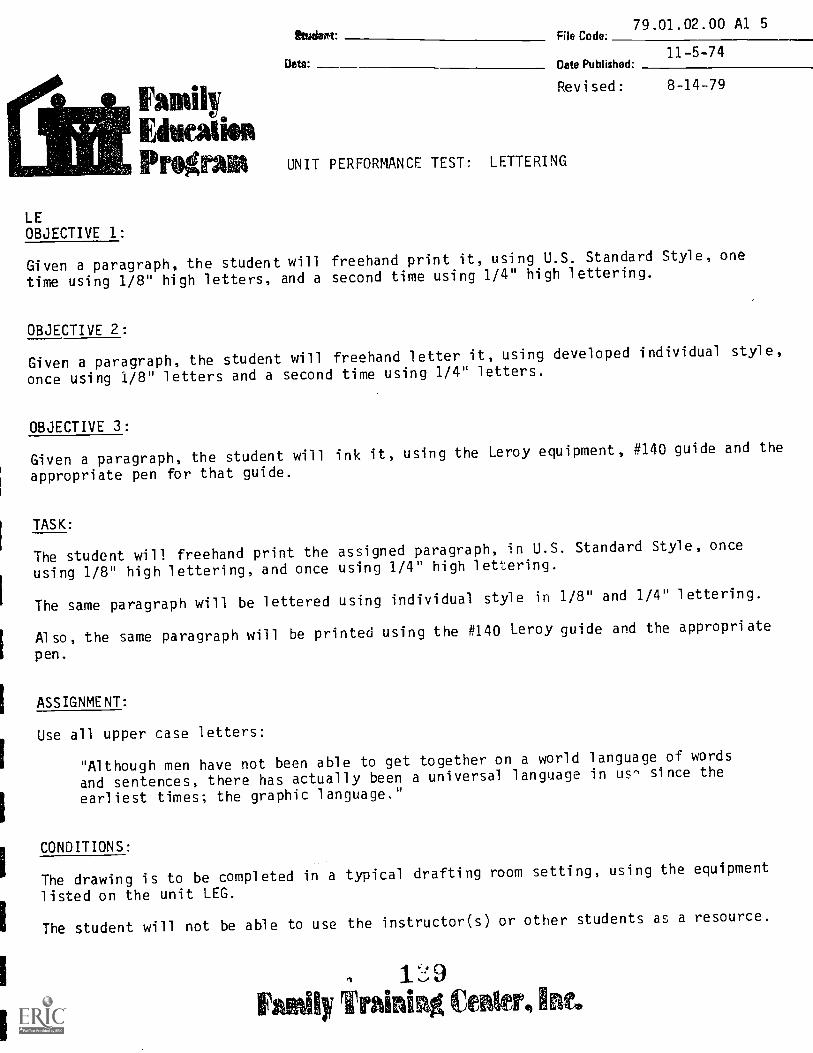
79.01.02.00 Al 5File Code.
Nnm11-5-74
Date Published-
Revised: 8-14-79
PrOgrain UNIT PERFORMANCE TEST: LETTERING
LEOBJECTIVE 1:
Given a paragraph, the student will freehand print it, using U.S. Standard Style, one
time using 1/8" high letters, and a second time using 1/4" high lettering.
OBJECTIVE 2:
Given a paragraph, the student will freehand letter it, using developed individual style,
once using 1/8" letters and a second time using 1/4" letters.
OBJECTIVE 3:
Given a paragraph, the student will ink it, using the Leroy equipment, #140 guide and the
appropriate pen for that guide.
TASK:
The student will freehand print the assigned paragraph, in U.S. Standard Style, once
using 1/8" high lettering, and once using 1/4" high lettering.
The same paragraph will be lettered using individual style in 1/8" and 1/4" lettering.
Also, the same paragraph will be printed using the #140 Leroy guide and the appropriate
pen.
ASSIGNMENT:
Use all upper case letters:
"Although men have not been able to get together on a world language of words
and sentences, there has actually been a universal language in us- since the
earliest times; the graphic language."
CONDITIONS:
The drawing is to be completed in a typical drafting room setting, using the equipment
listed on the unit LEG.
The student will not be able to use the instructor(s) or other students as a resource.
1:.; 9
iy Train! e,4
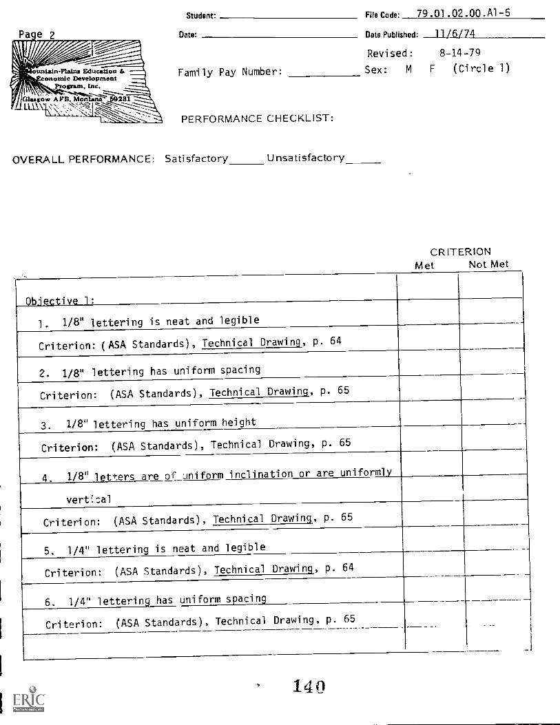
untain-Plains Education &anomie Development
Protpram, Inc.
Glasgow APB. Mon1.11\_ '\,`
Student. File Code: 79.01.02.00.A1-5
Date:
Family Pay Number:
PERFORMANCE CHECKLIST:
OVERALL PERFORMANCE: Satisfactory Unsatisfactory
Date Published: 11/6/74
Revised: 8-14-79
Sex: M F (Circle 1)
CRITERIONMet Not Met
Objective 1:
1. 1/8" lettering is neat and legible
Criterion: (ASA Standards), Technical Drawing, p. 64
2. 1/8" lettering has uniform spacing
Criterion: (ASA Standards), Technical Drawing, p. 65
3. 1/8" lettering has uniform height
Criterion: (ASA Standards), Technical Drawing, p. 65
4. 1/8" etters are of uniform inclination or are uniformly
vert;.:al
Criterion: (ASA Standards), Technical Drawing, p. 65
5. 1/4" lettering is neat and legible
Criterion: (ASA Standards), Technical Drawing, p. 64
6. 1/4" lettering spacing
Criterion: (ASA Standards), Technical Drawing, p. 65_
140

Page 3(Checklist continued)
79.01.02.00.A1-5
CRITERION
7. 1/4" lettering has uniform height
. .__
Criterion: (ASA Standards), Technical Drawing, p. 65
8. 1/4" letters are of uniform inclination or are uniformly
vertical
.
Criterion: (ASA STandards ), Technical Drawing, p.65
0bjective_2:
9. Leroy lettering is neat
Criterion: All letters consistent with the lettering guide, an' no unnec-ssary
lines. Technical Drawing, Giesecke, p. 80
10. All Leroy letters are of uniform weight.
Criterion: No irregular line weights
11. Proper spacing is used between all words and lines.
-81Criterion: (ASA Standards), Technical Drawing, Giesecke, pp. 7:
12. All words are correctly spelled in all exercises.
Criterion: Spelled exactly as given in the assigned task
13. The drawing is completed in soecified time limits
Criterion: Not to exceed 1-1/2 hours
The student must meet criterion on 10 line items to obtain an overall score
of satisfactory.
Student File Code.79.01.02.00:B2-2
Date:
UNIT POST TEST: LETTERING
Date Published.Revised:
79.01.02.01 __ U.S. Standard
1. The recommended angle for inclined American Standard lettering is:
a. 900b. 75°
C. 68°d. 60°
2. The lead recommended for lettering in this course is:
a. M
b. 2H
c. 4Hd. 6H
3-5-7912-03-79
3. In American Standard Lettering, the height of a lower case letter is what part of
the height of an upper case letter?
a. The same height.b. Half the height.
c. Two-thirds the height.d. Three-quarters the height.
4. The general rule for spacing letters within a word is:
a. The distance between letters should be the size of a zero.
b. The areas between letters should be about equal.
c. The distance between letters should be 1/32 of an inch.
d. The area between letters should be the size of a zero.
5. Guide lines for lettering should be used:
a. Neverb. Rarely
c. Only on 1/8" lettersd. Always
79.01.02.02 __ Ames Lettering Guide
6. Guide lines drawn with the Ames Guide are drawn with:
a. 6Hb. 4H
c. 2Hd. H
7. If the reference mark on the Ames Guide is set at 10, what will be the height of
the letter?
a. 1/10"b. 5/8"
c. 5/16"d. 1/32"
8. The proper relationship of whole numbers to fraction is shown in:
1 2
Page 2 79.01.02.00:82-2
9. The requirement(s) for free style lettering is (are):
a. Consistant c. Legible
b. Neat d. All of these (a, b, and c)
10. Space between one line and the next is:
a. 1/8" c. Letter heightb. 2/3 letter height d. 1/4"
79.01.02.03 -- LeRoy Lettering Guide
11. In your set, you have a LeRoy Template KE-61-0300-120CL. What is the nominal height
of the letter?
a. .120 inch c. 120 millimeters
b. 12/32's d. .300 inches
12. With the LeRoy, the tracer pin follows the:
a. Edge of the T-squareb. Letters on the templatec. Horizontal guide grooved. edge of the template
13. The LeRoy Automatic Reservoir Pens consist of:
a. 7 partsb. 5 parts
c. 3 partsd. 2 parts
14. The evenly divided spaces on the edge of the lettering guide are used:
a. To measure the height of the letters.b. To space lines.c. To space letters on a line.d. Instead of an architect's scale.
15. Which tenpl ate do wo use for 1/4" letters?
a. 2c.5CL
b. 175CL
c. 140CLd. 120CL
1 13

79.01.02.00:B2-2Revised: 12-03-79
UNIT POST TEST ANSWER KEY: LETTERING
79.01.02.01
1. C
2. A
3. C
4. B
5. 0
79.01.02.02
6. A7. C
8. C
9. D
10. B
79.01.02.03
11. A
12. B
13. B
14. C
15. B
Mountain-Plains Education fdEconomic Development
Program. Inc.
Glasgow AFB. Montana 692
RATIONALE:
7(1010300.A2-1File Code:
Date Published: 10-21-75
Revised: 8-15-79
R@ondriaE nap@ced@uom ig@odd@
UNIT: GEOMETRIC CONSTRUCTION
Much of the work produced by the draftsman is based on plane geometry. However, the
true geometric method allows only the use of a straightedge and a compass. In Geometric
Construction, you are allowed to use any instrument to do the job with greater speed.
The construction problems which will be studied in this Unit are those most often used
by draftspersons to solve problems and to construct working drawings.
PREREQUISITES:
Unit: 79.01.02 -- Lettering
OBJECTIVES:
Apply the principles of Geometric Construction by making a drawing of an object from a
given illustration.
Identify the terms, principles and techniques used in Geometric Construction.
RESOURCES:
Printed Materials
Basic Technical Drawing. Spencer and Drydon, Macmillan Company, New York.
Engineering Drawing and Graphic Technology. French and Vierck, Eleventh Edition,
M McGraw-Hill Book Company, New York.Mechanical Drawing. French and Svenson, Webster Division, McGraw-Hill Book Company,
New York.Technical Drawing__ Sixth Edition, Giesecke, Mitchell, Spencer and Hill, Macmillan Co.
4udi o/Vi sual s
Video cassette for Unit 3.
Equipment
As listed in Course LEG.
GENERAL INSTRUCTIONS:
This unit consists of 22 Learning Activity Packages (LAPs). Each LAP will provide
specific information for completion of a learning activity.
Principal Author(s): C. Wetterl in g
Revised: J. Wheatley
11,5
Page 2 79.01.03.00:A2-1
GENERAL INSTRUCTIONS: (continued)
The general procedure for this unit is as follows:
1) Read the first assigned Learning Activity Package (LAP).2) Begin and complete the first assigned LAP.3) Take and score the LAP test.4) Turn in the LAP test answer sheet.5) Determine the reason for any missed items on the LAP test.
6) Proceed to and complete the next assigned LAP in the unit.
7) Complete all required LAPs for the unit by following steps 3 through 6.
8) In this unit, there are some LAPs that have tests combined with other LAP tests.
These combined tests are taken after completing the last LAP covered by the test.
9) Take the unit tests as described in the unit LEG "Evaluation Procedures"
10) Proceed to the next assigned unit.
PERFORMANCE ACTIVITIES:
.01 Dividing a Line into Equal Parts
.02 Bisecting a Line
.03 Enlarging a Drawing
.04 Bisecting an Angle
.05 Copying an Angle
.06 Triangle Construction
.07 Constructing Equilateral Triangles -- Compass and Triangle Method
.08 Square Construction -- Compass and Triangle Method
.09 Inscribing a Square in a Circle -- Triangle and Compass Method
.10 Circumscribing a Square About a Circle -- Triangle and Compass Method
.11 Inscribing a Pentagon in a Circle -- Divider and Geometric Construction Methods
.12 Compass Method of Inscribing a Hexagon in a Circle
.13 Hexagon Construction
.14 Constructing an Octagon
.15 Rectifying an Arc
.16 Drawing an Arc Through Three Points
.17 Drawing a Line Tangent to a Circle
.18 Drawing an Arc Tangent to an Arc and Line
.19 Drawing an Arc Tangent to Two Intersecting Lines
.20 Drawing an Arc Tpioent to Two Arcs
.21 Ellipse Construction Trammel , Concentric Circle, and Compass Method
.22 Applying Techniques of Geometric Construction
EVALUATION PROCEDURE:
1. The student takes the LAP multiple-choice pretests. Successful completion is
8 out of 10 items for each LAP.2. The student takes a multiple-choice unit post test and a unit performance test.
Successful unit completion if meeting the listed criteria for the performance test.
FOLLOW-THROUGH:
The skills of Geometric Construction attained in this Unit shall be the basis for con-
struction in future drawings and shall be monitored throughout the entire Course.
NOTE: Do all your drawings on the back of the LAP sheets.
Go to the first assigned LAP listed on your Student Progress Record (SPR).
116

..... , . ountaln-Plains Education &% 7 : onomic Development
iiGlasgow AFB. Mon
oaam. Inc.----....,_-_--------
,_59231\ ...,\"'*..7.2 --..... --.
X-: -,-. .._-...\''..---....,--_-_,,,,....,..:.
79.01.03.02.
Student. File Code: 79.01.03.00. A2-2
Date- Date Published. 6/20/74
UNIT PRETEST: GEOMETRIC CONSTRUCTION
1 . Bisect means divide into:
a. two equal parts.b. two parts.c. three equal parts.d. three parts.
2. Which is the method for bisecting?
a. )
79.01.03.03.
1
3. A diagonal is:
a line passing through the center of a sphere.b. a line through two points on an arc.c. a line from corner-to-corner in figure.d. another name for a diameter.
4. A circ Iscrit-ed regular polygon is:
a. a secant.b. drawn inside of a circle.c. drawn around a circle.
Id. cut off on one end not parallel to the base .

79.01.03.00. A2 2
79.01.03.03. continued:
5. A line or drawing may be enlarged or reduced by:
a. inscribing the regular polygon.b. drawing diagonals of a geometrical figure to form similar triangles.c. bounding the plane figure with straight lines.d. bisecting the diagonals.
79.01.03.04.
6. A line segment extending from the center of a circle to the curve is:
a. a chord.b. a diameter.c. a radius.d. a secant.
7. To divide into two equal parts means to:
a. inscribe.b. bisect.c. erect a perpendicular.d. trisect.
79.01.03.05.
8. An angle measuring less than 90 degrees is said to be:
a. acute.b. obtuse.c. scalene.d.
9. A triangle with one 90 degree angle is:
a. right triangle.b. equilateral triangle.c. scalene.d. obtuse.
10. A triangle with three sides equal and three angles equal is:
a. obtuse.b. equilateral.c. isosceles.d. scalene.

79.01.03.00. A2-2
79.01.03.06.
11. Arcs having the same center are said to be:
a. concentric.b. scalene.c. secant.d. chorded.
79.01.03.08.
12. The construction shown below is a solution to the problem of:
a. constructing an equilateral triangle.b. constructing a right triangle from three given sides.c. constructing a perpendicular to line AB.d. bisecting line AB.
A
79.01.03.17,18,19,
13. A hexagon has:
a. .h.vr,
L. six sides.c. 1/8".d. eight sides.
8
14. The combination of instruments shown below that are used to constructa hexagon is:
a. 1 and 2.b. 2 and 3.c. 1 and 3.d . 1 and 2 and 3.
1 19 A

79.01.03.00. A2-2
79.01.03.24.
15. To draw a circle through three given points:
a. use one of the given points as center.b. construct perpendicular bisectors of two chords of the arc.c. lay off the length of the arc first.d. draw a right polygon with the points ai the corners.
79.01.03.25,26,27,28.
16. To obtain a smooth joint between tangent lines:
a. terminate the lines at the point of tangency.b. overlap the lines slightly.c. draw one of the lines just short of the point of tangency.d. draw both lines short of the point of tangency and then MI it in.
17. When drawing tangencies on an ink tracing, draw:
a. all the curved lines First.b. all the straight lines first.c. construction lines heavy and dark so they can be seen easily.d. the tangent lines in pencil on the tracing, then ink over the pencil.
18. When tracing tangencies in ink, it helps to:
a. mark the points of tangency with a pencil.b. mark the points of tangency with a pen.c. not n iark the points of tangency.d. rub pounce into the pencil copy of the tangencies.
79.01.03.39
19. The first lines to ink on a drawing are:
a. circles arcs.b. horizontal lines.c. vertical lines.d. border lines.
20. When corrections are needed on a pencil drawing that is to be inked:
a. make the correctiom; in pencil beforZ-,b. make the corrections in ink as you come to them.c. make the ink copy, mark the errors, and redraw it.d. make the ink copy, then erase and correct errors.

79.01.03.00. A2-2
UNIT PRETEST ANSWER KEY: GEOMETRIC CONSTRUCTION
LAP
02 1. A2. B
03 3. C4. C5.
04 6. C7.
05 8. A9. A
10. B
06- 11. A24 12. A
13.14. C15. B
25- 16. D32 17. D
18. A
19. A20. A
1 11
Mount& EducationEconomic Development
Program, Inc.
Glasgow AFB, Montana 69231
?ERFORMANCE ACTIVITY:
79 01 03 01 ;A2 -flFile Code.
Date Published. 11-4-75
Revised: 8-15-79
Learning Activity Package
Dividing a Line 'r`° EqL al
Student:
Dow
Parts
OBJECTIVE:
Divide a given line into equal parts using a geometric construction method.
EVALUATION PROCEDURE:
The instructor will check the procedure of the construction and check the accuracy
with a divider. No errors are allowed on this LAP.
Successful completion of this LAP is determined by correctly answering 8 out of 10
items on a multiple-choice test that is combined with "Enlarging a Drawing LAP test
and is taken after completing LAP .03.
RESOURCES:
Basic Technical Drawing, pg. 71 (Fig. 5-2 and 5-3)
Basic Drafting Tools: (see Unit LEG)
Drafting Furniture: (see Unit LEG)
PROCEDURE:
1. Read the resource(s).
2. On the back of this paper divide three lines into the following parts:
(Do not use your sc.ale except to draw the given line to length)
Line AB 3 5/8 long into 3 equal parts.Line CD 6 7/32 long into 7 equal parts.Line EF 4 1/2 long into 5 equal parts.
3. Write the definition for the following words on this sheet (use good freehand
lettering) and illustrate the definition with a sketch:
parallelperpendicularverticalhorizontalinclined
4. Have the work evaluated.
Principal Author(s): C. Wetterling, S. Vosen
Revised: J. Wheatley

Mountain-Plains P.ducation &1,P:comically Lievphomenl,
Printrant, Inc.
Mugu* A l'111. Wraranio 69231
File Code: 79.01.03.02.242-0
Date Published' 11j4 /75
Revised Date: 8-15-79
Learnin Activit ackage
PERFORMANCE ACTIVITY: _BISECTING A LINE
OBJECTIVE:
Student:
Date:
Bisect a given line using first, the triangle method, and second the geometricconstruction or compass method.
EVALUATION PROCEDURE:
The instructor will check the procedure of construction and accuracy of thework with a divider or scale. No errors are allowed on this LAP.
Successful completion of this LAP is determined by correctly answering 8 outof 10 items on a multiple-choice test that is combined with "Enlarging a Drawing"LAP test and is taken after completing LAP 03.
RESOURCES:
Basic Technical Drawing, pg. 71 (Fig. 5-5)Technical Drawing, pg. 91 (Fig. 4.8 and Fig. 4.9)
Basic Drafting Tools: (See Unit LEG)
Drafting Furniture: (See Unit LEG)
PROCEDURE:
1. Read the above n-zource(s) for the two procedures for bisecting a line.
2. B.-3ect each line below twice, once using the triangle method, anCI once using
the geometric construction method. (Compass method).
Line 1:Line 2:Line 3:
2 7/8 inches1 3/4 inches3 inches
3. Write definitions for the following terms on the same drawing sheet usinggood freehand lettering:
BisectIntersect
4. Have the work evaluated.
Principal Author(s): C. Dvorak
Revised by: S. Vosen, J. Wheatley
1 S3

-
Mountain-PlaInn Foducat Ion &Kcon000l Lkvrloprnnnt
Proictarn. Inr.
Morrow AI It, Muntana 69231
030301 179A-0File Code.
Date Published 11/4/75
Date Revised: 3/5/80
Learning Activity PackageStudent:
PERFORMANCE ACTIVITY: ENLARGING A DRAWING
OBJECTIVE:
Enlarge a drawing using the proportional dividers.
EVALUATION PROCEDURE:
Date:
The instructor will evaluate the procedure and check the accuracy of the workusing a scale and dividers. No errors are allowed.
Successful completion of this LAP is determined by correctly answering 8 outof 10 items on a multiple-choice test.
RESOURCES:
Technical Drawing, pg. 40 (para. 2-41 & Fig. 2.50)Instructions for Using Proportional Dividers.Basic Drafting Tools: (See Unit LEG)Drafting Furniture: (See Unite LEG)Proportional Dividers
PROCEDURE:
1. Read the above resource(s).
2. PraCtice ..nth :tie proportional dividers and apply it to the drawing shown
below.
3. Enlarge the drawing to twice its original size on a separate sheet of paper.
NOTE: Do not use a scale to make the enlargement.
4. List 2 other means of enlarging a drawing.
Principal Author(s): C. Dvorak
Revi!-;ed by: S. Vosen, J. Wheatleyl r 4
5. Have your work evaluatedand take the LAP test.
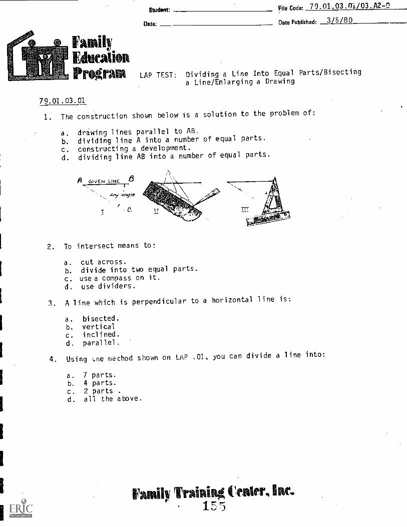
Studevrt File Code. 79.01.03.01/03.A2-0
Date:
FamilyEducation
Date Published: 3/5/8 0
PrOgrala LAP TEST: Dividing a Line Into Equal Parts/Bisecting
a Line/Enlarging a Drawing
79.01.03.01
1. The construction shown below is a solution to the problem of:
a. drawing lines parallel to AB.
b. dividing line A into a number of equal parts.
c. constructing a development.
d. dividing line AB into a number of equal parts.
A, GIVEN LINE
Any angle
Ia
2. To intersect means to:
a. cut across.b. divide into two equal parts.
c. use a compass on it.d. use dividers.
3. A line which is perpendicular to a horizontal line is:
a. bisected.b. verticalc. inclined.d. parallel.
4. Using 't.ne mechod shown on LAP .01, you can divide a line into:
a. 7 parts.b. 4 parts.c. 2 parts .
d. all the above.
Family TrainiRg tleRier,1,7

Page 2
79.01.03.02
5. Bisect means to divide into:
a. two Qqual parts.h. two parts.c. three equal parts.d. three parts.
79.01.03.01/03.A2-0
6. Which is the geometric method for bisecting a line?
a.
b.
c.
d.
7. The triangle method of bisecting a line uses which angle of the triangles?
a. 30°
b. 45°c. 60°d. all of the above.
8. An example of a diagonal is:
a.
b.
79.01.03.03
c.
d. e9. The prop6rtional dividers should be set on what number to double or
;salve a dimension?
a. 1
b. 2
c. 3
d. 1/2
10. Which of the following is NOT a method used to enlarge a drawing?
a. Inclined Methodb. Diagonal Methodc. Grid Square Methodd. Proportional Method

LAP
01 1. D
2. A
3. B
4. D
02 5. A
6. B
7. D
8. B
03 9. B
10. A
LAP TEST ANSWER KEY:
Dividing A Line Into Equal Parts/Bisecting a Line/Enlarging A Drawing
157
79.01.03.01/03.A2-03/5/80

Mounts In-PlaInn RI:Wu* non &Itconortile- LlevellPment
Prt.grdm,
(11assow AVIS. Kostrina 59231
File Code. 79. 01.03 .04 .AI -0
Dale Published 11/4175Date Revised: 3/5/80
Learning Activity PackageStudent:
PERFORMANCE ACTIVITY:BISECTING AN ANGLE
OBJECTIVE:
Bisect a given angle using the compass method.
EVALUATION PROCEDURE:
Date:
Successful completion of this LAP is determined by correctly answering 8 out
of 10 items on a multiple-choice test that is combined with "Copying An Angle"
LAP test and is taken after completing that LAP.
RESOURCES;
Basic Technical Drawing, pg. 72 (Fig. 507).
Basic Drafting Tools: (See Unit LEG)
Drafting Furniture: (See Unit LEG)
PROCEDURE:
1. Read the above resource(s) for the procedure to bisect an angle.
2. Practice this method by bisecting all the angles of the following
triangles: (See page 2.) Do not use your protractor to bisect the angles.
3. What must the sum of the interior angles of a triangle total? degrees
4. Measure each angle with a protractor. Write your answers below:
A=
B=
C=
degrees
degrees
degrees
E=
F=
G=
degrees
degrees
degrees
M =
0=
degrees
degrees
degrees
5. Wri;:e the definition for the following terms (use good freehand lettering):
A. Radius B. Arc C. Angle
6. Have your work evaluated, and go on to LAP .05. The LAP test will be
taken after LAP .05.
Principal Author(s): C Wetterling
Revised by: S. VosenJ. Wheatley IZ9
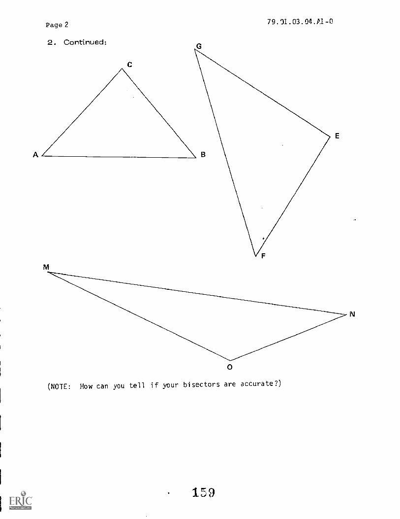
Page 2
2. Continued:
79.31.03.04.A1-0
M
0
(NOTE: How can you tell if your bisectors are accurate?)
MoUntadn4WirmliWumMon&Rcemontir LtevrloPMent
Pre warn, Inc.
Illassow AFII, Wiliam* 60231
File Code: 79.01.03.05.A2-0
Date Published: 11/4/75Date Revised: 8 -15 -7Q
Learning Activity Package
PERFORMANCE ACTIVITY: COPYING AN ANGLE
OBJECTIVE:
Student:
Date:
Copy a given angle at .a new location using the compass method.
EVALUATION PROCEDURE:
Instructor will check work for the proper procedure and accuracy of transferring
an angle to a new location. An allowance of 1/20 will be considered satisfactory.
Successful completion of this LAP is determined by correctly answering 8 out
of 10 items on a multiple-choice test.
RESOURCES:
Basic Technical Drawing, pg. 72 (5-8)
Basic Drafting Tools: (See Unit LEG)
Drafting Furniture: (See Unit LEG)
PROCEDURE:
1. Read the above resource(s).
2. Copy the c llowing angles at teir new locations using the method given in
the Resource(s).
(See Page 2)
Principal Author(s): C. Dvorak
16n

Page 2
C
c
79.01.03.05.A2-0
E
DA-- Q
181

Page .3
Procedure: continued
79.01.03.05.A2-0
3. Give the definition for the following terms (use good freehand lettering).
A. Chord
B. Acute angle
C. Isosceles triangle
D. Right triangle
E. Scalene triangle
F. Vertex
G. Base (of a triangle)
H. Equilateral triangle
4. Have the instructor evaluate your work.
5. Take the LAP test.

FamilyEdition
Student. File Co 79.01.03.04/05Code: .A2-0
Date: Date Published. 6/20/74Revised; 3/5/80
1410041141114 LAP TEST: Bisecting An Angle/Copying An Angle
79.01.03.04
1. An example of a radius is:
a. (E)
b
d 02. A line segment extending from the center of a circle to the curve is:
a. a chord.b. a diameter.c. a radius.d. a secant.
3. A continuous portion of a circle or curve is:
a. a chord.b. a secant.c. an arc.d. a radius.
4. The figure formed by two lines extending from the same point is:
a. an angle.b. a secant.c. a polygon.d. a diagonal.
5. If all 3 angles of a triangle are bisected, the bisectors:
a. are parallel.b. are perpendicular.c. meet at one point.d. form a triangle.
79.01.03.05
6. A straight line joining two points on a curve is:
a. a radius.b. a chord.c. a diagonal.d. an arc.
FawAilw TraiRiitg tinders litre1 ;-b, 3

Page 2 79. 01 . 03 . 04/05 .A2-0
79.01.03.05 (continued')
7. A triangle with two sides equal and two angles equal is:
a. right triangle.b. scalene.c. obtuse.d. isosceles.
8. A triangle with one 90 degree angle is:
a. right triangle.b. equilateral triangle.c. scalene.d. obtuse.
9. A triangle with no sides or angles equal is:
a. i soscel es.
b. obtuse.c. equilateral.d. scalene..
10. The point of intersection of lines is called:
a. vertex.b. chord.c. secant.d. acute.
l'4

LAP TEST ANSWER KEY
Bisecting An Angle/Copying An Angle
LAP
04 1. B
2. C
3. C
4. A
5. C
05 6. B
7. D
8. A
9. D
10. A
79.01.03.04/05.A2-03/5/80

MountainPlain* Munition 6Valmont le Development
Program,
tltiontow Moniatut 69231
File Code:79.01.03.06.A1-0
Date Publishaq:11/4/75
Date Revised: 3 /5/80
Learning Activity Package
PERFORMANCE ACTIVITY: TRIANGLE CONSTRUCTION
OBJECTIVE:
Student:
Date:
Construct a triangle with three given sides using the compass method.
EVALUATION PROCEDURE:
The instructor will check your work for accuracy and proper procedure. No errors
are allowed on this LAP.
Successful completion of this LAP is determined by correctly answering 8 out of
10 items on a multiple-choice test that is combined with "Constructing Equila-
teral Triangles" LAP test and is taken after completing that LAP.
RESOURCES:
Basic Technical Drawing, pg. 72 (Fig. 5-9)
Basic Drafting Tools: (See Unit LEG)
Drafting Furniture: (See Unit LEG)
PROCEDURE .
1. Read the above resource(s).
2. Construct three triangles with the following given sides (use the procedure
outlined in the reference material):
(See Page 2)
Principal Author(s): C. Dvorak
Revisions: J. Wheatley

Pi
BI
C
0I
Page 2 7q.01.03.06.A-0
IA
IN
SI
R
RI
I M
N
T
1 T
3. Give the definitions for the following terms (use good freehand lettering).
a) Hypotenuse
b) Concentric arcs
c) Conrentric circles
4. Have the instructor evaluate this LAP.

Mountain-Plains Education laEconomic Development
Program, Inc.
Glasgow AFB. Montana 69231
Re Co de.79.01.03.07:A1-0
Date Published: 11-4-75
Revised: 3-5-80
Learning Activity PackageStudent:
PERFORMANCE ACTIVITYC
Ow:
onstructing Equilateral Triangles -- Compass and Triangle Methods
OBJECTIVES:
Given the side, construct an equilateral triangle using the compass method of construc-tions. Given the side, draw an equilateral triangle using the triangle method.
EVALUATION PROCEDURE:
The instructor will evaluate work for proper construction methods. No errors are
allowed on this LAP.
Successful completion of this LAP is determined by correctly answering 8 out of 10items on a multiple-choice test. The LAP test is taken after comoletina this LAP.
RESOURCES:
Basic Technical Drawing, page 72 (Fig. 5-11) and page 73 (Fig. 5-13a)
Basic Drafting Tools: (see Unit LEG)Drafting Furniture: (see Unit LEG)
PROCEDURE:
1. Read the above Resource(s).2. Construct thrcnc '..riangles with the given sides using both methods--(use back of
this sheet).
2 7/8" 3 1/16" 1 19/32"
3. Have the instructor evaluate your LAP.
4. Take the LAP test.
I
I
Principal Author(s): C. Dvorak, J. Wheatley
1C3
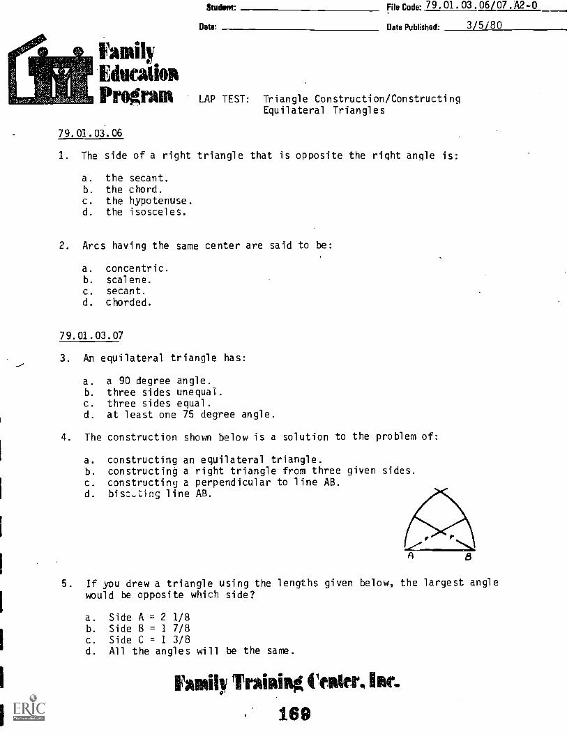
Studier File Code: 79 . 01 . 03. 06/07.A2-0
Date Date Published- 3/5/80
FamilyUtica lionPrograms LAP TEST: Triangle Construction/Constructing
Equilateral Triangles
79.01.03.06
I. The side of a right triangle that is opposite the right angle is:
a. the secant.b. the chord.c. the hypotenuse.d. the isosceles.
2. Arcs having the same center are said to be:
a. concentric.b. scalene.c. secant.d. chorded.
79.01.03.07
3. An equilateral triangle has:
a. a 90 degree angle.b. three sides unequal.c. three sides equal.d. at least one 75 degree angle.
4. The construction shown below is a solution to the problem of:
a. constructing an equilateral triangle.b. constructing a right triangle from three given sides.c. constructing a perpendicular to line AB.d. bisc..tir.g line AB.
A 8
5. If you drew a triangle using the lengths given below, the largest anglewould be opposite which side?
a. Side A = 2 1/8b. Side B = 1 7/8c. Side C = 1 3/8d. All the angles will be the same.
Family tinder, kr.169

LAP
06 1. C
2. A
07 3. C
4. A
5. A
LAP TEST ANSWER KEY:
Triangle Construction/Constructing Equilateral Triangles
170
79.01.03.06/07.A2-03/5/80

Mountain-Plains Education &Economic Development
Program, Inc.
Glugow AFB. Montana 69231
PERFORMANCE ACTIVITY:
OBJECTIVE:
79.01.03.08:A1-0File Code-
Date Published: 11-5-75
Revised: .3-5-80
Learning Activity PackageSwim
Date:
Square Construction -- Compass and Triangle Methods
Draw a square using the triangle method.Construct a square using the compass method.
EVALUATION PROCEDURE:
The instructor will visually inspect the construction checking for accuracy and proper
procedures. You will be allowed no errors on this LAP. The LAP test is combined
with LAPs 09 and 10.RESOURCES:
Basic Technical Drawing, page 73 (Fig. 5.13b)Technical Drawing, page 96 (para 4.23 and Fig. 4.23a)Basic Drafting Tools: (see Unit LEG)Drafting Furniture: (see Unit LEG)
PROCEDURE:
1. Read the above resource(s).2. Draw a square with a side of 2 3/8" using the triangle method on the back of this
sheet.
NOTE: DO NOT circumscribe a square about a cirqe.
3. Construct two squares using the compass method on the back of this sheet of paper.
One square have a diagonal measurement of 2 3/4".The cther square shall have a side of 1 3/8".
NOTE: DO NOT use the method of inscribing or circumscribing with a circle.
You are not allowed to use a T-square.
4. How many degrees does the sum of the interior angles of the square equal?
degrees
5. Have the instructor check your work.
6. Go on to the next LAP. The LAP test is combined with LAP s 09 and 10.
Principal Author(s): C. Wetterling, S. Vosen, J. Wheatley
171
lio un Lain-nal nit Education isEconomic Davisionment
Program, Inc.
Glasgow AFB. Montana 59231
File Code-79.01,03.09:A1-0
Date Published:11-5-75
REVISED: 3-5-80
Learning Activity PackageStudent:
Our
PERFORMANCE ACTIVITY:Inscribing a Square in a Circle -- Triangle and Compass Method
OBJECTIVES:
Inscribe a square in a circle using the compass method.
Inscribe a square in a circle using the triangle method.
EVALUATION PROCEDURE:
The instructor will visually inspect your work for accuracy and correct construction
procedure. You will be allowed no errors on this LAP. Successful completion of this
LAP is determined by the instructors evaluation and successful complet'on of the LAP
test.
RESOURCES:
Basic Technical Drawing, page 73 (Fig. 5.13d)
Basic Drafting Tools: (see Unit LEG)
Drafting Furniture: (see Unit LEG)
PROCEDURE:
1. Read the above Resource(s).
2. Use the triangle method to inscribe a square in a circle with a 4 1/8" diameter.
3. Study the following steps for inscribing a square in a circle using the compass
method.
Steps
A. Draw a circle with center Z with desired radius or diameter using a compass.
Princirm4AuthorIA: C. Dvorak, C. Wetterl ing, S. Vosen, J. Wheatley
172

Page 2Procedure: Steps continued
79.01.03,09: A1-0
B. Use a triangle as a straight edge for drawing line AC through
the center (Z) of the circle at an angle from the horizontal.
(NOTE: Do not use the "T"-square)
C. Use a compass to construct line BD perpendicular to line AC at point Z.
D. The four points (A, B, C & D) on the circle are the corners of the
desired square ABCD. Use a triangle as a straight edge to drawlines AB, BC, CD and DA, thus completing the inscribed square ABCD.
4. On a separate sheet inscribe a square in a circle having a two-inch
diameter. Use the compass method.
NOTE: Do not use a T-square.
5. Have the construction evaluated by the instructor.
6. The LAP test is combined with LAP 10. Proceed to next LAP.
173

Mountain-Plains Education &Economic Development
Program, Inc.
Glasgow AFFI, Montana 59231
I '
File Code79.01.03.10:A1-0
Date Published:11-5-75
Revised: 3-5-80
Learning Activity PackageStudint:
Oats:
PERFORMANCE ACTIVITY:Circumscribing a Square About a Circle -- Triangle and
Compass Methods
OBJECTIVES:
Circumscribe a square about a circle using the compass method. Circumscribe a square
about a circle using the triangle method.
EVALUATION PROCEDURE:
The instructor will examine drawing for accuracy and proper construction techniques.
No errors are allowed on work. Successful completion of this LAP is determined by
the instructors evaluation and scoring 80% on the LAP test.
RESOURCES:
Basic Technical Drawing, page 73 (Fig. 5.13c)
Basic Drafting Tool s: (see Unit LEG)
Drafting Furniture: (see Unit LEG)
PROCEDURE:
I. Read the above resource(s).2. Construct a square around a circle with a three-inch diameter using the triangle
method.3. Read the following steps.
Steps
A. Draw a circle with required diameter or radius.
CB. Using a triangle, draw a line VW through the center 7 of the circle. (NOTE:
Do not use your "1" square).
Principal Author(;): Q. FoglemanS. Vosen, J. Wheatley
174

Page 2Procedure: Steps continued
C.
79.01.03.10:A1-0
Construct perpendicular line XY at point Z using a compass.
D. Locate points A, B, C and D using a compass set at the radius of the circle.
E. Draw lines AB, BC, CD and DA. Square ABCD in the circumscribed square.
2. In a drawing, circumscribe a square about a 4 inch circle using the compassmethod.
NOTE: You are not allowed to use a T-square.
3. Have the construction evaluated by the instructor.
4. Take the combined LAP test. Proceed to the next LAP.

Student file Code: 79.01.03.08/09/10.A2-0
Clat Date Published. 3/5/80
EducationPingrain LAP TEST: Square Construction/Inscribing a Square in a
Circle/Circumscribing a Square About a Circle
79.01.03.08
1. A line drawn from one corner of a square to the opposite corner is a:
a. diagonal.b. perpendicular.c. parallel.d. hypotenuse.
2. A square is a:
a. regular polyhedron.b. regular polygon.c. irregular polyhedron.d. irregular polygon.
3. What is the sum of the interior angles of a square?
a.
b.
c.
d.
45g90
180°360-
79.01.03.09
4. The two diagonals of a square:
a. are the same length as the side of a square.b. are perpendicular and bisect each other.c. bisect the sides of a square.d. are the diameter of a circle inscribed in the square.
79.01.03.16
5. The diameter of a circle circumscribed around a square:
a. is the length of the diagonals of the square.b. is twice the length of a side of the square.c. is the length of a side of the square.d. cannot be found.
Fad!) TrAinikg Center, IIRe.
176

79.01.03.08/09/10.A2-03/5/80
LAP TEST ANSWER KEY:
Square Construction/Inscribing a Sauare in aCircle/Circumscribing a Square About a Circle
LAP
08 1. A
2. B
3. D
09 4. B
10 5. A
177

Mountain-Plains Education &Economic Development
Program. Inc.
Ulaagow APB. Montana 59231
File Code 79 01 03 11-A2-0
Date Published: 11-6-75
Revised: 8-15-79
Learning Activity PackageStudent'
Date:
PERFORMANCE ACTIVITY Inscribing a Pentagon In a Circle -- Divider and Geometric
Construction Methods.
OBJECTIVES:
Inscribe a pentagon in a given circle using the divider method.Inscribe a pentagon in a given circle using the geometric construction method.
EVALUATION PROCEDURE:
Successful completion of this LAP is determined by correctly answering 8 out of 10items on a multiple-choice test that is combined with "Drawing an Arc Through ThreePoints" LAP test and is taken after completing that LAP.
RESOURCES:
Technical Drawing, Page 97 (Fig. 4.24)Basic Technical Drawing, Page 73 (Fig. 5-13e)Engineering Drawing_ and Graphic Technology, Page 74Basic Drafting Toolir-(see Unit LEG)Drafting Furniture: (see Unit LEG)
PROCEDURE:
1. Read the following procedure for inscribing a pentagon in a circle:
a. Construct a circle of the given diameter.b. Open the divider to distance less than 1/4 of the circumference and as close
to 1/5 as you can estimate.c. From a starting point, A on the circle, mark five consecutive distances using
the divider as stet in Step (b).d. If your fifth mark falls on the starting point, you have successfully found
the five corners of the pentagon. Go to Step (e).If your fifth mark was short of the starting point, lengthen the distanceon your divider and take Steps (c) and (d).If your fifth mark was-past _the starting point, shorten ti-le distance on yourdividers and take Steps (c) dnO.N(d).
e. Connect the five corners of the peNtagon that you have located.
Principal Author(s): Q. Fogleman, S. Vosen, J. Wheatley
178

Page 2 79.01.03,11:A2-0
PROCEDURES: (continue')
2. Inscribe a pentagon in a circle with a 3 1/2 inch diameter using the reeceding
method.
3. Read the assigned Resource(s).
4. Inscribe a pentagon in a circle of 3 1/2 inch diameter using the geometric con-
struction method.
5. How many degrees is each interior angle?
6. Have the instructor evaluate your work.
7. Proceed to the next LAP.
MountainMinn gducation 6Economic Llevrhipment
Prug.r. rn,
(11airsow A VA. Montana 69 231
79.01.02.12:A2- 0File Code:
Date Published: 11/6/7 5
Date Revised: 8 -15 -7n
Learning Activity PackageStudent:
Date:
PERFORMANCE ACTIVITY-CGmfASS METHOD OF INSCRIBING A HEXAGON IN A CIRCLE
OBJECTIVE;
Inscribe a hexagon in a given circle using the compass method.
EVALUATION PROCEDURE:
The instructor will evaluate your work checking for accuracy and proper construction
techniques. You will not be allowed any errors on this LAP.
Successful completion of this LAP is determined by correctly answering S out of
10 items on a multiple-choice test that is combined with "Drawing an Arc Through
Three Points" LAP test and is ta:ccn after completing that LAP.
RESOURCES:
Basic Technical Drawing, pg. 73 (Fig. 5.13f)
Technical Drawing, pg. 97 (Fig. 4.25b)
Engineerinr, Drawing and Graphic Technologgy, pg. 73
Basic Drafting Tools: (See Unit LEG)
Drafting Furniture: (See Unit LEG)
PROCEDURE:
1. Rt,id the above resource(s).
2. Draw a circle with a 7 1/2 inch diameter on the back of this sheet.
3. Inseri.ve a hexao.n in the circle using the compass method described in the
reforence(s).
4. How many degree is each interior angle?
S. Have the instructor evaluate the construction.
Principal Autinmq0: J. Schye
Revised by: S. Vosen, J. Wheatley
180
Mountain-Mina Education dr.Economic Development
Program, Inc.
File Code. 79.01.03.13:A2-0
Date Published:11-6-75
Revised: 8-15-79
Learning Activity PackageStudest:
Dar
PERFORMANCE ACTIVITY:Hexagon Construction -- Given Distance Across Points or Flats
or Length of a Side.
OBJECTIVE:
Construct a hexagon given the distance across flats.Construct a hexagon given the length of its side.Construct a hexagon given the distance across points.
EVALUATION PROCEDURE:
Successful completion of this LAP is determined by correctly answering 8 out of 10
items on a multiple-choice test that is combined with "Drawing an Arc Through 11ee
Points" LAP test and is taken after completing that LAP.
RESOURCES:
Basic Technical Drawing, pg. 73 (Figures 5-13g, h, and i)
Technical Drawing., pg. 97 and 98 (para. 4.26, Fig. 4.26)
Basic Drafting Tools: (see Unit LEG)
Drafting Furniture: (see Unit LEG)
PROCEDURE:
1. Read the above Resource(s).2. On the back of this sheet construct (3) hexagons with the following information
given:
a) A hexagon with the side length Pi".b) A hexagon that is 21/4" across points.c) A hexagon that is 1 3/4" across flats.
3. Have your hexagons evaluated.
Principal Amitholi* J. Schye, J. Wheatley
181
Mountain-Mina EducationEconomic Development
Program, Inc.
Glasgow AFB, Montana 69231
File Code.79 01 03 14:A2-0
Date Published:11-6-75
Revised: 8-16-79
Learning Activity PackageStudent:
Date:
PERFORMANCE ACTIVITY:Constructing an Octagon
OBJECTIVE:
Circumscribe an octagon around a given circle.Inscribe an octagon in a given circle.Inscribe an octagon in a square.
EVALUATION PROCEDURE:
The instructor will evaluate your work checking for accuracy and proper construction
techniques. You will be allowed no errors on this LAP.
Successful completion of this LAP is determined by correctly answering 8 out of 10
items on a multiple-choice test that is combined with "Drawing an Arc Through Three
Points" LAP test and is taken after completing that LAP.
RESOURCES:
Basic Technical Drawing, page 73 (Figures 5 -13K, !I and N)
Technical Drawing, page 98 (Figure 4.28)
Basic Drafting Tools: (see Unit LEG)
Drafting Furniture: (see Unit LEG)
PROCEDURE:
1. Read the above resource(s).
2. Construct a 11/2" diameter circle, a 2" diameter circle, and a 2" square on the
back of this sheet.
3. Circumscribe an octagon around the 11/2" circle, inscribe an octagon in the 2"
circle, and inscribe an octagon in the square.
4. How mangy' degrees is each interior angle of an octagon? degrees
5. Have the construction evaluated.
Principal Author(s): C. Wetterl ing, S. Vosen, J. Wheatley
182

Mountain-Plains Education ieEconomic Development
Program, Inc.
Glasgow AFB. Montana 59231
File Codr79.01.03.15:A2-0
Date Published:11-6-75
Revised: 8-16-79
Learning Activity Package
PERFORMANCE ACTIVITY: Recti fyi ng an Arc
Student:
Date.
OBJECTIVE:
Lay off a given straight line on a given arc.
Lay off a given arc on a straight line.
EVALUATION PROCEDURE:
The instructor will evaluate your work checking for accuracy and proper construction
techniques. You will be allowed no errors on this LAP.
Successful completion of this LAP is determined by correctly answering 8 out of 10
items on a multiple-choice test that is combined with "Drawing an Arc Through Three
Points" LAP test and is taken after completing that LAP.
RESOURCES:
Basic Technical Drawing, page 73 (Figure 5-15)
Technical Drawing, page 106 (para. 4.46)
Basic Drafting Tools: (see Unit LEG)
Drafting Furniture: (see Unit LEG)
PROCEDURE:
1. Read the e-cve rasource(s).
2. Draw a line 2" long and an arc tangent to it with a 3" radius.
3. Lay off a 2" circumference on the arc using the method in Basic Technical Drawing.
4. Given a circle with a 2" diameter, lay off 1/6 of its circumference on a straight
line.
5. Have the constructions evaluated.
Principal Author(s): C. Wetterl ing, S. Vosen, J. Wheatley
193

MounLain-Plalms Falucation &Pktaiontir bevri"prrient
Probiram.
(Ilasitow Mon. 61nrstana 69231
File CodP,79 01 03 16-A2-0
Date Published 11/6/15Revised Date: 8 -16 -79
Learning Activity PackageStudent:
Date:
PERFORMANCE ACTIVITYConstructing an Arc Through Three Points
OBJECTIVE:Construct an arc through three given points.
EVALUATION PROCEDURE:
The instructor will evaluate your work checking for accuracy and proper
construction techniques. You will be allowed no errors on this LAP.
Successful completion of this LAP is determined by correctly answering
8 out of 10 items on a multiple-choice test.
RESOURCES:
Basic Technical Drawing, pg. 73 (Fig. 5-14)
Basic Drafting Tools: (See Unit LEG)
Drafting Furniture: (See Unit LEG)
PROCEDURE:
1. Read the above. resource(s).
2. Make th1-7_ points (A, B & C) on the back of this sheet.
The distance from A to B is 2 inches.
The distance from B to C is 3 inches.
The distance from A to C is 3 1/2 ...nches.
HINT: Construct a triangle with these 3 sides.
3. Draw a circle through the three points.
4. Have the construction evaluated.
5. Take the test.
Principal Author(s): J. Schye
Revised by: S. Vosen, J. Wheatley
184

Mtuntain-Plitanx nducatiem &Krim ttttt Ir Devetupinent
Yribgr4171. It Ir.
(!hallow A VII. Mwiturut 592:11
File Code79.01.03.17:A2-0
Date Published- 11/6/75Date Revised: 8-16-79
Learning Activity PackageStudent:
Constructing a Line Tangent to Rate:
PERFORMANCE ACTIVITY-Circle and a Circle Tangent to a Line
OBJECTIVE:
Construct a line tangent to a given circle at a given point on the circle. Draw a
circle tangent to a given line at a given point.
EVALUATION PROCEDURE:
Instructor will evaluate for accuracy and construction method with no errors
permitted.
Successful completion of this LAP is determined by correctly answering 8 out
of 10 items on a multiple-choice test that is combined with "Applying Techniques
of Geometric Construction" LAP test and is taken after completing that LAP.
RESOURCES:
Basic Technical Drawing, pg. 73 (Fig. 5-16) pg. 74 (Fig. 5-17)
Technical Drawing, pg. 101 (Fig. 4.33) & (Fig. 4.34)
Basic Drafting Tools: (See Unit LEG)
Drafting Furniture: (See Unit LEG)
PROCEDURE:
1. Bad the above resource(s).
2. On the other side of this sheet, draw a circle with a 2 inch diameter.
3. Mark a point on the circle and label it (A).
4. Construct a line tangent to the circle at point (A).
5. Draw a 3 inch long inclined line and construct a 1 1/2 inch diameter circle
tangent to the center point of the line.
6. Have your work evaluated.
Principal Author(s): C. Wetterling
Revised by: S. Vosen, J. Wheatley 185

Mountain-Plain/ Education &Economic development
Pro Kl4rn, 1nr.
(11aa110 w A l'11. Montana 69231
79,01.03.18:A2-0File Code.
Date Published: 11/6/75Date Revised: 8-16-79
Learning Activity PackageStudent:
Date:
PERFORMANCE ACTIVITY:Constructing an Arc Tangent to an Arc and Line
OBJECTIVE:
Construct an arc tangent to a given arc and a given line. (2 cases).
EVALUATION PROCEDURE:
Instructor will evaluate for accuracy and construction method with no errors
allowed.
Successful completion of this LAP is determined by correctly answering 8 out
of 10 items on a multiple-choice test that is combined with "Applying Techniquesof Geometric Construction" LAP test and is taken after completing that LAP.
RESOURCES:
Basic Technical Drawing, pg. 75 (Fig. 5-19, a & b)
Engineering Drawing and Graphic Technology, pg. 66, para. 15
Technical Drawing, pg. 104 (Fig. 4.39)Basic Drafting Tools: (See Unit LEG)
Drafting Furniture: (See Unit LEG)
PROCEDURE:
1. Read the above resource(s).
2. Case I - On the hack of this sheet, draw an arc with a radius of 3/4 inch.
3. Draw a line segment 1 inch from the arc.
4. Construct an arc with a 7/8 inch radius tangent to the given arc and line.
5. Find all points of tangency.
6. Case II - On the back of this sheet, draw an arc with a 4 inch radius.
7. Draw a line passing thru the center of the arc and intersecting the arc.
8. Construct a 1/2 inch radius arc tangent to the given arc and line. Mark the
points of tangency.
9. Have the instructor evaluate the construction.
Ptincirmiiekuthoi(s):C. Wetterling
Revised by: S. Voson, J. Wheatley1 8
Wurliwn-PW1rIAPAiumMlon&Mconcingir Loevelroment
Pratt/JAM, Inc.
(11usitow A1.11, Mim1.4sna 69231
rile Code79 01 03 19-P9-0
Date Published 11/6/75
Date Revised: 8-16-79
Learning Activity PackageStudent:
Due.
PERFORMANCE ACTIVITY:Constructing an Arc Tangent to Two Intersecting Lines
OBJECTIVE:
Construct an arc tangent to two intersecting lines.
EVALUATION PROCEDURE:
Instructor will evaluate for accuracy and construction method with no errors
allowed.
Successful completion of this LAP is determined by correctly answering 8 out
of 10 items on a multiple-choice test that is combined with "Applying Techniques
of Geometric Construction" LAP test and is taken after completing that LAP.
RESOURCES:
Basi: Technical Drawing, pg. 74 (Fig. 5-18).
Basic Drafting Tools: (See Unit LEG)
Drafting Furniture: (See Unit LEG)
PROCEDURE:
1. Read the above re:ource(s).
2. On the back upperhalf of this sheet, draw two perpendicular inte2,ecting lines.
3. On the lower half of the sheet, draw two intersecting lines that are not
perpendicular.
4. Construct an arc with radius of 1 inch and tangent to both lines in each
intersecting set.
5. Find and mark all points of tangency.
6. Have your construction evaluated.
Principal Author(s): C. wetterling.7 187

Mour taln-Pluirta Mug:0.ton &fr.cononsio. Llevetisprtent
Pro trim,
(ilassuw Ark. Muria:ins 69231
File Code: 79.01.03.20IA2-0
Date Published. 11/6/75
Date Revised: 8-16-79
Learning Activity PackageStudent:
Date:
PERFORMANCE ACTIVITY:Constructing an Arc Tangent to Two Arcs
OBJECTIVE:
Construct an arc tangent to two given arcs. (2 Cases)
EVALUATION PROCEDURE:
Instructor will evaluate for accuracy and construction method with no
errors allowed.
Successful completion of this LAP is determined by correctly answering 8 out
of 10 items on a multiple-choice test that is combiend with "Applying Techniques
of Geometric Construction" LAP test and is taken after completing that LAP.
RESOURCES:
Basic Technical Drawing, pg. 75 (Fig. 5-19)
Engineering Drawing and Graphic Technology, pg. 67, para. 16
Technical Drawing, pp. 104 & 105 (Figures 4.40 & 4.41)
Basic Drafting Tools: (See Unit LEG)
Drafting Furniture: (See Unit LEG)
PROCEDU-2E:
1. Read the above resource(s).
2. Case I - cm., back of this sheet, draw two circles a short distance apart:
One, with a radit, of 1 inch.
Second, with 3/4 inch radius.
3. Construct an arc with a 2 inch radius that is tangent to both ci-:les.
4. Find all points of tangency.
5. Case II - Draw two circles the same size as Case I, with 2 inches between
centers.
6. Construct an arc with a 4 inch radius tangent to both given circles. Mark
the tangency points.
7. Have the construction evaluated.
PrincipallNuftmr(s): C. Wetterling
Revised by S V7)sen, J. Wheatley 183

Mounts LnPlains Education IsEconomic Development
Program, Inc.
Glasgow APB, Montana 69231
File Code 79.01.03.21:A2-0
Date Published. 11-6-75
Revised: 8-16-79
Learning Activity PackageStudent:
Date:
PFRFORMANCE ACTIVITY: Trammel , Concentric Circle, and Compass Method
of Ellipse Construction
OBJECTIVE:
Draw an ellipse using the trammel method.Draw an ellipse using the concentric circle method.Draw an ellipse using the compass (4 center) method.
EVALUATION PROCEDURE:
Instructor will evaluate for accuracy and construction method with no errors allowed.
Successful completion of this LAP is determined by correctly answering 8 out of 10
items on a multiple-choice test that is combined with "Applying Techniques of Geometric
Construction" LAP test and is taken after completing that LAP.
RESOURCES:
Basic Technical Drawing, pg. 76 (Fig. 5-21, 5-22 and F-23)
Basic Drafting Tools: (see Unit LEG)
Drafting Furniture: (see Unit LEG)
PROCEDURE:
1. Read the above resource(s).2. On the back of this sheet, draw a horizontal line 3 inches long, construct a
perpendicular bisector to this line.
3. Using the trammel method, construct an ellipse with a major axis of 3" and a minor
axis of 2°.4. Construct an ellipse with a 4" major axis and a 2" minor axis using the concentric
circle method.5. Construct dn ellipse with a 4" major axis and a 1 3/4" minor axis using the com-
pass (4 point) method.6. Have your :instructions evaluated.
Principal Author(a): C. We ',erling, J. Wheatley
1 n

klountraln-Plain Education &Economic Development
Program, Inc.
Glasgow AFB, Montana 0231
79.01.03.22:A2-0File Code:
2-16-75Date Published:
Revised: 8-16-79
Learning Activity PackageStudent:
Date:
PERFORMANCE ACTIVITY : Applying Techniques ofGeometric Construction
OBJECTIVE:
Draw two objects applying the techniques of geometric construction.
EVALUATION PROCEDURE:
The instructor will examine the drawings for accuracy and proper construction tech-
niques. Three errors will be allowed.
Successful completion of this LAP is determined by correctly answering 8 out of 10
items on a multiple-cho4ce test.
RESOURCES:
Previous 1 APsBasic Technical Drawing, Chapter 5.Technical Drawing, Chapter 4.Engineering Drawing and Graphic Technology, Chapter 3.
Basic Drafting Tools: (see Unit LEG)
PROCEDURE:
1. Draw a border and title block in ink with the ruling pen
this LAP.
2. Draw the two problems given in this LAP using techniques
Make sure the drawings are centered.
using the format given in
of geometric construction.
NOTE: Use a Fhe et of 12" x 18" drawing paper for these two
3. Identify all points of tangency.
4. When completed, have the instructor evaluate the drawings.
5. Take the LAP test.
Principal Author(s): C. Wetterl ing , S. Vosen , J. Wheatley
190
drawings.

Page 2 79.01.03.22:A2-0
1ti
CAST IRON
.62 DIA - t:15
2 HOLES
Material --Forged Steel
Rocker Arm.
instructor for proper format.
4
1
CAST BkONZE
.746-.750 REAM
40
Material --Cast Iron
I.123-1.1?5kt AM
Gear Arm.'5V
See instructor for proper format.
191
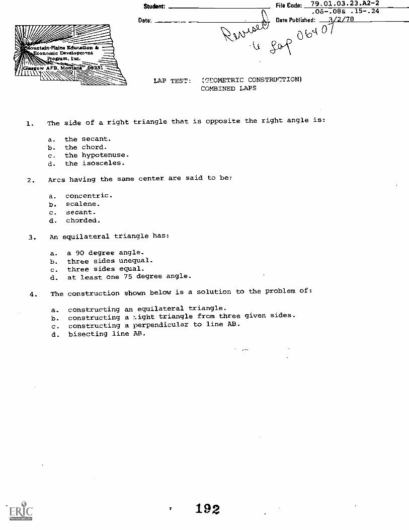
ountatin-Plains Echvaition tFmarmite Develtspnrrnt
ogram,
Student File Code: 79.01.03.23 . A2-2
Date:
.Oo .08& .15.24Data Published: 2L78
LAP TEST: ;r_.=170METRIC CONSTRUCTION)
COMBINED LAPS
1. The side of a right triangle that is opposite the right angle is:
a. the secant.b. the chord.c. the hypotenuse.d. the isosceles.
2. Arcs having the same center are said to be:
a. concentric.b. scalene.c. secant.d. chorded.
3. An equilateral triangle has:
a. a 90 degree angle.b. three sides unequal.c. three sides equal.d. at least one 75 degree angle.
4. The construction shown below is a solution to the problem of:
a. constructing an equilateral triangle.b. constructing a -sight triangle frcm three given sides.
c. constructing a perpendicular to line AB.
d. bisecting line AB.
192
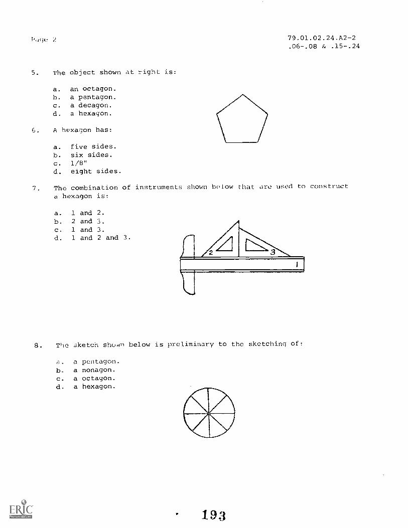
1,,,gc. 2 79.01.02.24.A2-2.06-.08 & .15-.24
5. The object shown at right is:
a. an octagon.h. a pentagon.c. a decagon.d. a hexagon.
6. A hexagon has:
a. five sides.b. six sides.c. 1/8"
d. eight sides.
7. The combination of instruments shown below that are used to construct
a hexagon is:
a. 1 and 2.b . 2 and 3.c . 1 and 3.d. 1 and 2 and 3.
8. Tho sketch shown below is preliminary to the sketching of:
a. a pentagon.b. a nonagon.c. a octagon.d. a hexagon.
193

Page 379.01.02.24.A2-2.06-.08 & .15-.24
9. To lay off the approximate length of an arc, use:
a. dividers.b. the T-square.c. an ellipse template.d. ruling pen.
10. To draw a circle through three given parts:
a. use one of the given points as a center.
b. construct perpendicular bisectors of two chords of the arc.
c. lay off the length of the arc first.d. draw a right polygon with the points at the corners.
194

79.01.03.24. A2-2.06-.08 8t .15-.24.
LAP TEST ANSWER KEY: COMBINED LAPS (GEOMETRIC CONSTRUCTION)
L C2. A3. C4. A5. B6. B7. C8. C9. A
10. B
195

17/.1':-' .
1.1 -adult-Nam,' F.:ducatIon & -73)
DCWEIOPITIent.r.,;tratri, !me.
,1(:lulg...,..; A s:Fi. P.17t11.n.a 231
Student: Code: 79.01.03.32.A2-2
Late Published: 6/20/74
Date Pevised: 3/3/78
;.AP TEST: COMBINED LAPS (GEO'LETRICCONSTRUCTION)
To find the tangency point off two circles, draw:
a. a :_raight line connecting the circle centers.b. a perpendicular to the arcs.c. a straight line pari,-liel to the plane of intersection.
d. an arc with radius of R + Rl.
To find the tangency point of a straight Line and a circle, draw:
a perpendicular to the straight line from the circle center.
b. a straight line parallel to the given line.
o. an arc with radius R and its center on the straight line.
d. an arc with radius of R + Ri.
3. To obtain a smooth joint between tangent lines:
a. terminate the lines at the point of tangency.
b. overlap the lines slightly.c. draw one of the lines just short of the point of tangency.d. draw both lines short of the point of tangency and then till it in_
4. To construct an arc tangent to a line, and passing thru a given point; you
would:
a. draw a perpendicular from the point to the line and use it for the
center of the ar(.b. construct a line parallel to the given line and radius of the are from
it, then swing the arc from the given point. Where they intersect is
The center the arc.
c. sng . of gi.v radius from both the line and the point. Where they
interect is the ::enter.d. there is no way to construct this figure.
5. To construct an arc tangent to two intersecting lines, you would:
a. bisect the angle and measure the radius of the arc au_ from the vertex.
b. step of the radius on each leg of the angle, then swing the radius
from these points. Where they intersect is the center of the arc.
c. construct 2 lines parallel to the given lines, the radius of the arc away
from the given lines. Where they intersect is the center of the tangent
arc.
d. none of the methods listed above work.
196

Page 2 79.01.03.32. A2 -2
.25- .32
G. Referring to the construction below, what is the correct geometric method
of making a line tangent to two arcs?
a. there is no correct geometric method.h. swing 2 arcs from the center of the given circles.
c. construct a perpendicular from the line to the center of the circle.
d. bisect the distance between the two arcs and construct a radius from
the line.
7. An ellipse is a geometric figure with:
a. one center and all points equidistant from that center.
b. a variable center axis.c. a major and minor diameter which may vary.
d. two center and all points equidistant from both centers.
8. The method of drawing an ellipse shown at right is:
a. the concentric circle method.
b. the trammel method.c. the axis method.d. the approximate four-center method.
9. The ear Lafici r,t11( ; draw o1.lipF;0
a. a template.
b. by the 4 center method.c. by the concentric circle method.d. by the trammel method.The first lines to in3,: on a drawing are
a. circles and arcs.b. horizontal lines.c. vertical lines.d. border lines.
197

79.01.03.32.A2-2.25- .32
LAP TEST ANSWER KEY: COMBINED LAPS (GEOMETRIC CONSTRUCTION)
1. A2. A
4.
5. C
6. A
7. CB. D
9. A
10. A
19g

/iii-- --
untain-Plainn Education & -71):conornIc Development. --
Proram, Inc.
iGhtslio v., AFB, Montana' _59231."\
OBJECTIVE 1:
Date: ____
File Code.79.01.03.00.A1-5
Oate Published: 11/6/74Date Revised: 8-16-79
UNIT PERFORRANCE TEST: GEO'iETRI.0 CONSTRUCTiON
Given an illustration of an object, the student will be able to construct the object
using correct geometric construction techniques.
OBJECTLVE 2:
The student will be able to properly ink the border and title block.
OBJECTLVE 3:
The student will be able to geometrically construct an object that is properly
centered, neat, and accurate to the given dimensions.
OBJECTIVE 4:
The student will be able te draw lines, arcs, and circles that are:
(a) Neat
(b) Properly drawn
(c) Weighted to appropriate contrasts
OBJECTLVE 5:
The student will he a'Dle to geometrically locate all points of tangency.
TASK:
Using the given dimensions, the student will make a finished drawing of an
assigned it
ASSIGNIAENT:
Using a sheet of 12" x 18" drawing paper, the student will reproduce the form
r I Ilever shown (jo P a ky! 2.
199
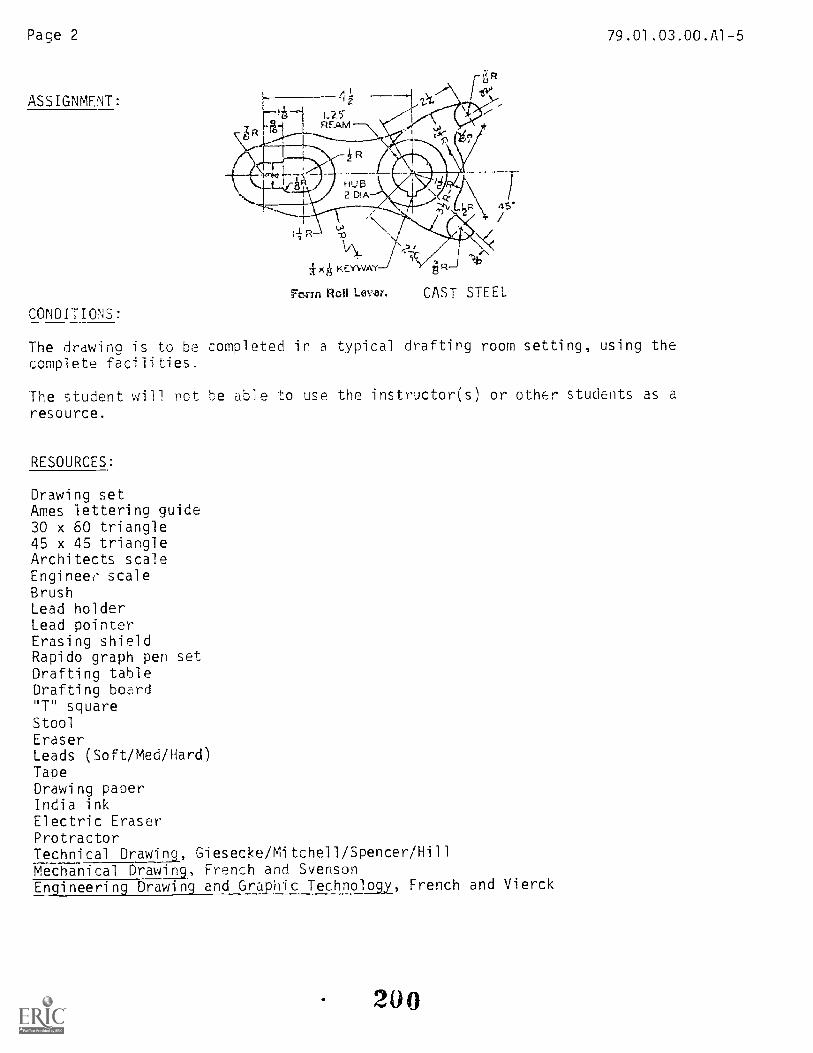
Page 2
ASSIGNMENT:
CONDITIONS:
Fcvan Roll Lever. CAST STEEL
79.01.03.00.AI-5
The drawing is to be completed in a typical drafting room setting, using thecomplete facilities.
The student will not be able to use the instructor(s) or other students as aresource.
RESOURCES:
Drawing setAmes lettering guide30 x 60 triangle45 x 45 triangleArchitects scaleEngineef' scaleBrushLead holderLead pointerErasing shieldRapido graph pen setDrafting tableDrafting board"T" squareStoolEraserLeads (Soft/Med/Hard)TapeDrawing paperIndia inkElectric EraserProtractorTechnical Drawing, Giesecke/Mitchell/Spencer/HillMechanical Drawing, French and SvensonEngineering Drawing and Graphic Technology, French and Vierck
200

:
ountain-Plain.n EducaTiononornic Development
Prowxnnt, Inc.
Glasgow: AFB. Nionicn,' 59231
Studont: _ _
Dale
79 01. 03. 00 .A1-5He Code: __
IThkrOPMANCE CHECKLIST:
Date Published: 117'6/74
Date Revised: 2-16-79
GEOMETRIC CONSTRUCTION
OVERALL PERFORMANCE. Satisfactory __Unsatisfactory_
Ob.lective 1:
1. Uses correct geometric construction techniques.AL!. lines meeE and- a-TT-angles are accurate to -J
Criterion: within 10.
Objective 2:
2. Border and title-block are inked correctly.
CRITERIONMet Not Met. _
Criterion: Border will be inked, using Rapidograph pen #2, ald Leroy T mplate #17"
Border line spacing will be 1/2". Three part tit e block s acing will
}-)e length 5/16" spacing. Four part wiL1 be 5" i length
with 7/16" spacing.
Objective 3:
--
_3. Drawing is clean and neaL.
Criterion: (ASA Standard), Technical Drawing, p. 12-22
4. Drawing is centered.
Criterion: (ASA Standars)
2 0 1

Page 4 79.01.03.00.A1-5
(Checklist k_ontinue(1)
CRITERIONMet Not Met
5. Total drawing is accurate to given dimensions
Criterion: plus or minus 1/64'; plus or minus 1°
Objective 4:
b6. Visible lines are net and properly drawn
Criterion: (ASA Standards). Technical Drawing, p. 20
7. Center lines are neat and properly drawn
Criterion: (ASA Standards), Technical Drawina, p. 20
8. Visible lines arc of appropriate contrast in relation to th
other lines.
Criterion: (ASA Standards), Technical Drawing, p. 20
9. Center lines are of appropriate contrast in relation to
other lines.
Criterion: (ASA Standards), Technical Drawing, p. 20
Objective 5:
10. All points of tangency are marked and are correct
Criterion: o Points tangency are left unmarked---------
---
11. The drawing is completed in specified time limits.
Criterion: Not to exceed 5 hours
Student must meet criterion on 8 line teens to obtain an overall score of
satisfactory.
202
------
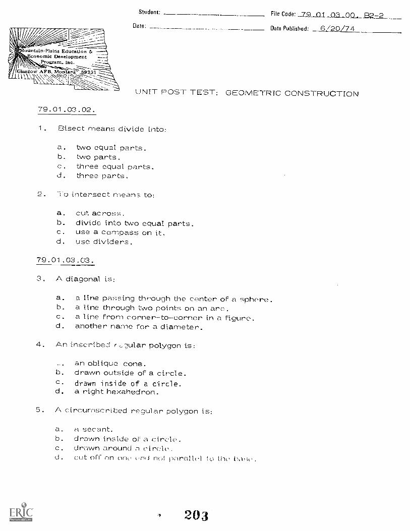
=; F
)untaln-Plnlna Education &onomic Development
Program, Inc. -- -1----":"--...".......z.............,------
Glasgow AFB. MonUri/2' 69231V\1`.N".- .:.,:---2, :-.,..--::":-. -----il
1_\_,_ ',s. 1'_;._' --.:-...,._-: -:=....1.1....-----,:.
79.01.03.02.
Student: File Code: 79 _01 03 On. -2Date: Date Published 6./20/74
UNIT POST TEST: GEOMETRIC CONSTRUCTION
1. Bisect means divide into:
a. two equal parts.b. two parts.c. three equal parts.d. three parts.
2 To intersect means to:
a. cut. across.b. divide into two equal parts.c. use a compass on it.d. use dividers.
79.01.03.03.
3. A diagonal is:
a. a line passing through the center of a sphere.b. a line through two points on an arc.c. a line From corner-to-corner in a Figure.d. another name for a diameter.
4. An inscribed r,_;,iular polygon is:
an oblique cone.b. drawn outside of a circle.c. drawn inside of a circle.d. a right hexahedron.
5. A circumscribed regular polygon is:
a. a secant.b. drawn inside or a circle.c. drawn around nd. cut off on one end net p\rallcI to tht, ,
203

79.01.03.00. B2 -2
79.01.03.04.
6. The interior angles of any triangle total up to:
a. more than 0 degrees but less than 90 degrees.b. 90 degrees.c. 180 decrees.d. more than 90 degrees but less than 180 degrees.
7. An example of a radius is:
h.
d.
79.01.03.05.
8. An angle measuring less than 90 degrees is said to be:
a. acute.b. obtuse.c. scalene.d. isosceles.
9. The of a from which the height is measured is:
a. the vertex.b. the base.c. the secant.d. the scalene.
10. A triangle with three sides equal and three angles equal is:
a. obtuse.b. equilateral.c . isc.soel es .d. scalene.
204

79.01.03.15,16.
11. The object shown below is:
a. an octagon.b. a pentagon.c. a decagon.d. a hexagon.
79.01.03.17,18,19.
12. A hexagon has:
a. Five sides.b. six sides.c. 1/8".d. eight sides.
79.01.03.00. B2-2
13. The combination of instruments shown below that are used to constructa hexagon is:
a. 1 and 2.b. 2 and ''.; .
c.1 2 and 3 .

79.01.03.00. 02-2
14. To lay off the approximate length of an arc, use:
a. dividers.b. the T-square.c. an ellipse template.d. ruling pen.
79.01.03.24.
15. To draw a circle through three given points:
a. use one of the given points as a center.h. construct perpendicular bisectors of two chords of the arc.c. lay off the length of the arc first.d. draw a right polygon with the points at the corners.
79.01.03.25,26,27,28.
16. To Find the tangent point of a straight line and a circle, draw:
a. a perpendicular to the straight line that passes through thecircle center.
b. a straight line parallel to the given line.c. an arc with radius R and its center on the straight line.d. an arc with radius of R + R1.
17. When drawing tangencies on an ink tracing, draw:
a. all the curved lines first.L. all the s)-raight lines first.c. .,c_ti,-)n lines and dark so they can be seen easily.d. the tangent lines in pencil on the tracing, then ink over th...?, pencil.
18. When tracing tangencies in ink, it helps to:
a. mark the points of tangency with a pencil.b. mark the points of tangency with a pen.c. not mark the points of tangency.d. rub L.Dunce into the pencil copy of the tangencies.

79.01.03.29,30,31.
19. The method of drawing an ellipse shown below is:
a. the concentric circle method.b. the trammel method.c. the axis method.d. the approximate Four - center metKod.
79.01.03.32.
79.01.03.00. E32 -2
20. When corrections are needed on a pencil drawing that is to be inked:
a. make the corrections in pencil before inking.b. make the corrections in ink as you come to them.c. make the ink copy, mark the errors and redraw it.d. make the ink copy, then erase and correct errors.
207

Revised: 12-03-7979.01.03.00 92-2
UNIT POST TEST ANSWER KEY: GEOMETRIC CONSTRUCTION
LAP
02 1. A2. A
03 3. C4. C5. C
04 6. C7. B
05 8. A9. 8
10. 9
06 11. B24 12. B
13. C14. A15. B
25 16. A
32 17. D18. A19. D
20. A

a
FARM ly
Program
RATIONALE:
File Code: 79. 01 . 04 . 00 . A2 -1
Date Published. 10-24-79
1-iooTriAmci: kap@r?d@rimo® @elitid®UNIT: SHAPE DESCRIPTION
A drawing is a form of non-verbal communication. In order to draw an object, we needto understand its shape. This shape may be described in either an orthographic orisometric drawing. A thorough understanding of each method helps develop the abilityto visualize the object and simplify the drawing process.
PREREQUISITES:
Unit: 79.01.03 -- Geometric Construction
OBJECTIVES:
Apply various orthographic and isometric lettering, numbering and projection techniquesto the sketching and drawing of given objects. Add missing lines and views to incompleteorthographic drawings.
PRINTED MATERIALS
Basic Technical Drawih_g_. Spencer and Drydon, MacMillan Company, New York, 1968.Engineering Drawing and Graphic Technology. French and Vierck, Eleventh Edition,McGraw-Hill Book Company, New York, 1973
Mechanical Drawing. French and Svenson, Webster Division, McGraw-Hill Book Company,New York, 1968.
Technical Drawing. Gieseche, Mitchell , Spencer and Hill, Sixth Edition, MacMillanCompany, New York, 1974.
'Drafting Rules and Principles. Howard C. Nelson, McKnight and McKnight, Bloomington,Ill., 1958.
Design Drafting. Earle, Addison-Wesley Publishing, London.
AUDIO/VISUALS
Drafting Series ..-.;naoe Descr eclay Media
Video Cassette for Unit 4.
EQUIPMENT
See Course LEG.
PrinCPC.3 (0: S. Vose , 1. V. `leatley
209MAW Falai! Ce r, in&
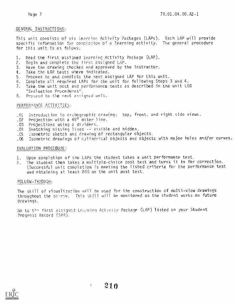
Page 2 79.01.04.00. A2-1
GENERAL INSTRUCTIONS:
This unit consists of six Learninc Activity Packages (LAPs). Each LAP will providespecific information for completion of a learning activity. The general procedurefor this unit is as folows:
1_ Read the first assigned Learning Activity Package (LAP).2. Begin and complete the first assigned LAP.3. Have the drawing checked and approved by the instructor.4. Take the LAP tests where indicated.5. Proceed to and complete the next assigned LAP for this unit.6. Complete all required LAPs for the unit for following Steps 3 and 4.7. Take the unit post and performance tests as described in the unit LEG
"Evaluation Procedures".8. Proceed to the next assigned unit.
PERFORMANCE ACTIVITIES:
.01 Introduction to cri:hographic drawing: top, front, and right side views.
.02 Projection with a 45° miter line.
.03 Projections using a dividers.
.04 Sketching missing lines -- visible and hidden.
.05 Isometric sketch and drawing of rectangular objects.
.06 Isometric drawings of cylindrical objects and objects with major holes and/or curves.
EVALUATION PROCEDURE:
1. Upon completion of the LAPs the student takes a unit performance test.2. The student then takes a multiple-choice post test and turns it in for correction.
(Successful unit completion is meeting the listed criteria for the performance testand obtaining at least 801 on the unit post test.
FOLLOW-THROUGH:
The skill of visualization will be used for the construction of multi-view drawingsthroughout the cc arse. This skill will be monitored as the student works on future
drawings.
Go to th^ first assignd Leininq Activity Package (LAP) listed on your StudentProgress Record (SPR).

OBJECTIVE 1:
Eto.exat:
Dote:
File Code: 7 9.01.04.00
Date Published: 1 1(1 7
Revised; 11-14-79
PERFORMANCE TEST: SHAPE DESCRIPTION
Given two isometric objects, the student will be able to make an orthographic sketchand an orthographic :Irawing of the objects to required scale.
OBJECTIVE 2:
Given two orthographic objects, the student will be able to make an isometric sketchand an isometric drawing cf the objects to approximate scale.
TASK:
1. The student will make an orthographic sketch from dimensioned isometric sketch #1.Use size "B" drawing paper. Divide sheet into four equal rectangles. Do not useborder or title block. Scale = Full.
2. The student will make an orthographic drawing from dimensioned isometric drawing #2.Center your drawing in one rectangle. Scale: 1" = 11/2".
3. The student will make an isometric sketch from dimensioned orthographic sketch #3,using appropriate sketching conventions from Chapters 2 and 16, Basic Drawing.Sketch is to be double in size.
4 The student will make an isometric drawing from dimensioned orthographic drawing #4.Scale = Double.
ASSIGNMENT:
See attached illustration. Space drawings evenly on size "B" drawing paper. No border
or title lock necessry.
CONDITIONS:
The drawing is to be completed in a typical drafting room setting, using the completefacilities. The student will not be able to use the i_itructor(s) or other studentsas a resource.
RESOURCES:
As listed in Unit LEG.
211Fmk Ifthininei

Page 2
\ . ,
1. ___.i
2,
I
z
T
3
212
79.01.04.00
It4
//- \
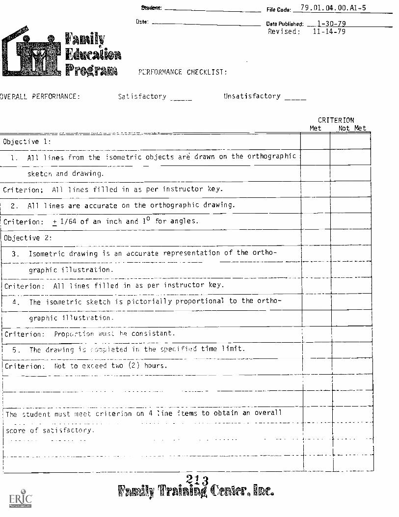
Educate-
rogra
OVERALL PERFORMANCE:
?Waft File Code: 79.01.04.00.A1-5
PERFORMANCE CHECKLIST:
Sat isfactory
Date Published: 1-30-79Revised: 11-14-79
Unsatisfactory
CRITERIONMet Not Met
Objective 1:
1. All lines from the isometric objects are drawn on the orthographic
sketch and drawing.
Criterion; All lines fill ed in as per instructor key.
2. All 1 ines are accurate on the orthographic drawing.
Criterion: + 1/64 of an inch and 10 for angles.
Objective 2:
3. Isometric drawing is an accurate representation of the ortho-
__
graphic illustration.
Criterion: All lines filled in as per instructor key.
4. The isometric sketch is pictorially proportional to the ortho-
graphic illustration.
Criterion: Proportion must he consistant.L
5. The drawing is comp 1 eted in the spec i fi,A time limit.
Criterion: Not to exceed two (2) hours.
T h e student must meet criterion on 4 line ;terns to obtain an overall
score of satisfactory.
II__ ....... _ _ . ..
___ ____
....
1
Tratroing imeo
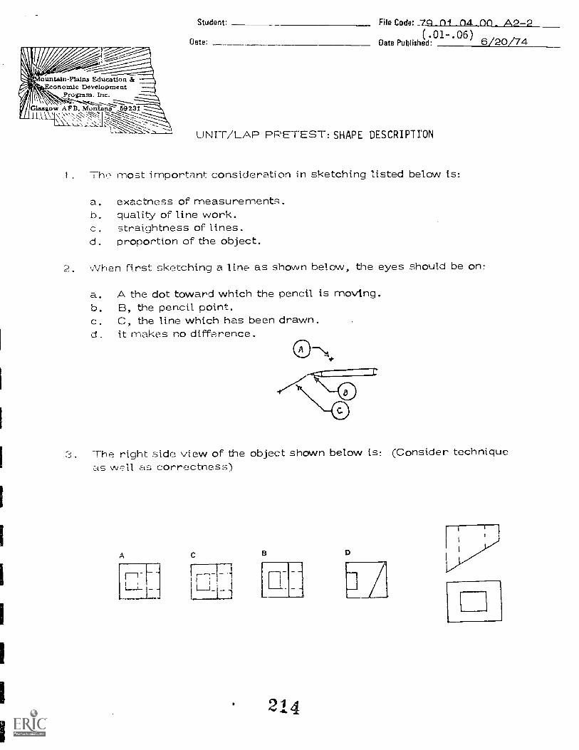
V1.6.1.k,....oun, Wm-Plains Education &
l: Glasgow A.;":-..!Vior-i-ta--7--,..1592311
onomic DevelopmentRrogram, Inc.
\-\1T"T'''' -.--':-----------1.; -- ----..--.--Z---, --:-.
Student: File Code: 7Q 01 04 _ 00 - A2-2Date:
( .01.06)Date Published: 6/20/74
UNIT /LAP PRETEST: SHAPE DESCRIPTION
1. The most important consideration in sketching listed below is:
a. exactness of measurements.b. quality of line work.c. straightness of lines.d. proportion of the object.
2. When first sketching a line as shown below, the eyes should be on:
a. A the dot toward which the pencil is moving.b. B, the pencil point.c. C, the line which has been drawn.d . it makes no difference.
The right side view of the object shown below is: (Consider techniqueas wr.11 CtS correctness)
C B
214

Page 2 79.01.04.00. A2-2(.01-.06)
4. A sketch made according to the axis sho rn below would be:
a. an orthographic sketch.b. an isometric sketch.c. a perspective sketch.d. an oblique sketch.
S. The lines shown below are often drawn to improve accuracy whensketching:
a. a hexagon.b. a circle.c. a sque-ed. pentagon.
h. The top view of the object shown below shoOld look like:
0
7. Most mechanical ideas are first shown in a:
. Finished working drawing.h. coroplet blue print.c. text hook.d. freehanci
i. The b../p(_ of lead to u,-;e for tsketching
1iL. I I orc. 411 or 01 I.d. 1-113 or V.
2i 5
A
\ A

Page 3 79.01.04.00 . A2-2(.01-.06)
9. The most important rule in freehand sketching is to:
a. concentrate on line weight quality.b. make the sketch to an accurate scale.c. keep the sketch in proportion.d. be sure to erase all construction lines.
10. The three regular views in a sketch are:
. width, height, depth.b. top, front, leftside.(;. top, Front, rightside.d. elevator, plan, section.
216
79.01.04.00. A2-2(.01-.06)
UNIT/LAP PRETEST. ANSWER KEY: SHAPE DESCRIPTION
1.2. A3. C4 D5. B6. 07. D8.9, C
10. C

Filo Code.79.01.04.01 A2-0
Oats Published:Revised:
January 31, 1979October 26, 1979
:min ctivit ckageStuart:
Date:
PER7-"ORMANICE ACTiVITY: Introduction to Orthographic Drawings:lop, Front, Right Side Views
OBJECTIVES:
I. Given an object and a glass box, draw the top, front and right side views as theyappear or each plane of the box.
2. Given an isometric sketch, complete the required orthographic view in the areaprovided on the assigned sheets.
EVALUATION PROCEDURE:
Using a prepared key, the instructor will examine drawings to see if the drawings arecorrect. Students are expected to correct or repeat drawings until there are no errors.
RESOURCES:
Design Drafting, Unit 7.Basic Technical Drawing, Chapters 2, 6, and 7.Technical Drawin2_, Chapter 6.Basic Drafting Tools: (see unit LEG)Drafting Furniture: (see unit LEG)Audio/Visual Material: (see unit LEG)
PROCEDURE:
1. Read Resorce(s) listed and view the filmstrips and video tape.2. You ar i7. learnin pew way of viewing "things" around you. Do not expect this skill
to be Jc ml=ch practice and many exercises may be necessary beforeyou can ,Le a tw,. dimensionl view of the object. This skill will come easierif you practice. When you go home tonight, pick some objects and look at them fromthe top, front, and right side.
3 Obtain the "Glass Box" and felt marking pen from instructor.a. Choose two of the objects available. One object should hay, a curved surface,
the other object should have an angled surface.b. Place one object in the glass box and draw top, front and right side of the
object on the box planes of projection.c. Hale drawing checked by instructor, then erase the marks on the box.d. Repeat the process with second object.
4. Work through the exercises on pages 2, 3, and 4.S. Have the instructor check your work. Then take the LAP test and go on to LAP 2.
PrincipisA Author(s): S. Vosen, J. Wheatley
21E3aleissailhe Wiperizatiskas facitoza hike

?age 79.01.04.x01 -- 3-26-79
DIRECTIONS: Sketch the surface(s) of the object which you would see if you looked throughthe glass plane ir the direction of the arrow () . Each square is equal to one inch.Which orthographic view are you drawing:
1-177-7,11-1
I
T 7
i
_1
I
, i
I ,
! I I
1 7-777
I
IMEIM12/R
,
;
1
219

Page 3 79.01.04.01 -- 3-26-79
DIRECTTONS: ketch the surfaces) of the object which you would see if you looked throughthe glass plane in t;,2 directiol of the arrow (--ig Each square is equal to one inch.
Which orthograhic vic,.! are you drawing:
, \/)) \ s)
11.)
)-7-7
//
A
,3\; I
'4,..+Z-Ci:-.17=1.112776"2.21f.....,',...7:14157.-.4-;.- 46'
77`...?V;
r"".....,,
LEUISANZMIZelanal=r1M
I -1

Pale 4 7q.01.04.01 -- 3-26-79
:RECTIONS: Sketch the surface(s) of the object which you would see if you looked through the
ass plane in the direction of the arrow ()).-0. Each square is equal to one inch_ Which or-
)ographic view are you Hr""'inn:
221

ram
aud.mt: File Code: 79.01.04.01.A2-0
Date: - Onto Pub:ighed: 1/16/79.Revised: 2/21/80
LAP TEST: INTRODUCTION TO ORTHOGRAPHIC PROJECTION --TOP, FRONT, RIGHT SIDE VIEWS
1. Orthographic drawings and sketches:
a. are normally shown as three views.b. require a back view if you have a left-side view.c. can be represented by only five views.d. according to drafting standards, you may not project the right-side view
off of the edge of the top view.
2 The most commonly used lines of sight are:
a. at any angle other than 90° to the front, top, or side of the object.b. perpendicular to the top, front, or right side of the object.c. directly at the outer corner of the object.d. so that you can see the three object dimensions at once.
3. Each standard plane of projection:
a. has only one dimension in common with the view next to it.b. has two dimensions, each of which can be projected to the adjacent view.c. is at a 75° angle to the adjacent plane of projection.d. will give you all the dimensions you will need to locate the plane or
planes seen in each view.
4. An angled plane surface will appear as:
a. a line when you look perpendicular to it.b. its own shape in two views out of three.c. a line in the front view if it is a line in the top view.d. a point if viewed parallel to the surface of the plane.
5. A vertical ()v. :_,r.:ontal plane face:
a. will appear distorted in two of the three standard views.b. will appear as a surface in the top view if it is seen as a line in the
right side view.c. will not appear as a hidden line mirror image in the view opposite to it.d. will appear as itself in one view only and as a line in the remaining
two views.
TrAining fettier Ine222

1. A
2. B
3. A
4. B
5. 0
LAP TEST ANSWER KEY:
INTRODUCTION TO ORTHOGRAPHIC PROJECTIONTOP, FRONT, RIGHT SIDE VIEWS
223
79.01.04.01.A2-02/21/80

Etta AkaProgram Learnin
FOeCodo: 79.01.04.02: A2-0
Date Published: -79Revised: 10-31-79
ctivity PackageStUdfillri :
Date'
PERFORMANCE ACTIVITY: jarajgc_juaLath_AA52__Eitexiing_
IOBJECTIVE:
Add missing views to various incomplete drawings, using the 45o
projection line technique.
I EVALUATION PROCEDURE:
1 Instructor will examine drawings to see if all missing lines have been added. Student1 must have all drawings correct.
RESOURCES:
Basic Technical Drawing, Chapter 6 and Chapter 7Design Drafting, Unit 7IBasic Drafting Tools: (see unit LEG)Drafting Furniture: (see unit LEG)
PROCEDURE:
1. Read Resource(s):
SAMPLE PROBLEM: Find the right side view of the object above by projecting from thetwo given views. (Review paragraph 7.11 and figures 7.13 and 7.14 in yourBasic Technical Drawing. Review page 152, Design Drafting).
IPrincipe! Auttior(s): S. Vosen, J. Wheatley
allemeAurilistatuskingtesataw
224

Pa rie 2
5
5
79.01.04,02: A2-0
SOLUTION:
Step A: Since the top and rpht side view have depth in common, project this depthdimension to the 45 construction line and down to the side view.
Step B: Project the width dimension from the top view to the front view. Project theheight from the front view to the right side view.
Number surfaces of sketch 1 and sketch 2 on the following objects. You do nothave to number object 3 or 4 if you can locate points without doing so.
Transfer numbers and letters to all views using the 45° projection method andcomplete the missing view for each object.
DRAW
225
e'KETCIR
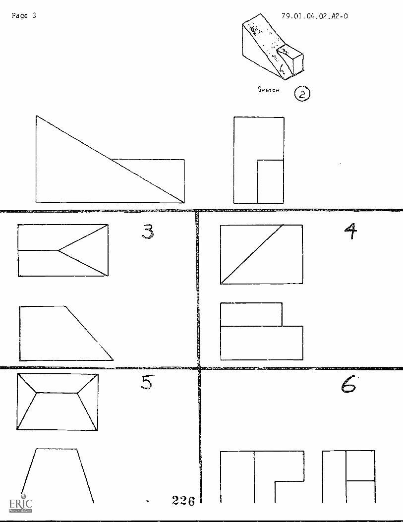
Page 3 79.01.04.02.A2-0
akarCH
3
226 Ti

Page 4 79.01.04.02: A2-0
PROCEDURE: (continued)
2. Using size "B" drawing paper and the 45° projection method, draw three views ofobjects #3, 5, and 10 on page 98, objects #2, 7, 8, 9, 11, 12, 14, 16, and 19 onpage 99 of Basic Technical Drawing. You will not use a border or title block onthis drawing. The objects will all be drawn on one sheet of paper. Six on each side.
3. Take the LAP test before going on to the next LAP.
227

DIRECTIONS:
1. Letter all surfaces.2. Number each surface as it appears in each view.
3. Project and transfer numbers to complete the missing view.
2 2 8
79.01.04.022-28-79Supplemental Exercise

Page 2
. t.V.,17..rfeSPG,01,10,1.1, PTA. ., M lad
4229
79.01.04.02Supplemental Exercise
3-28-79
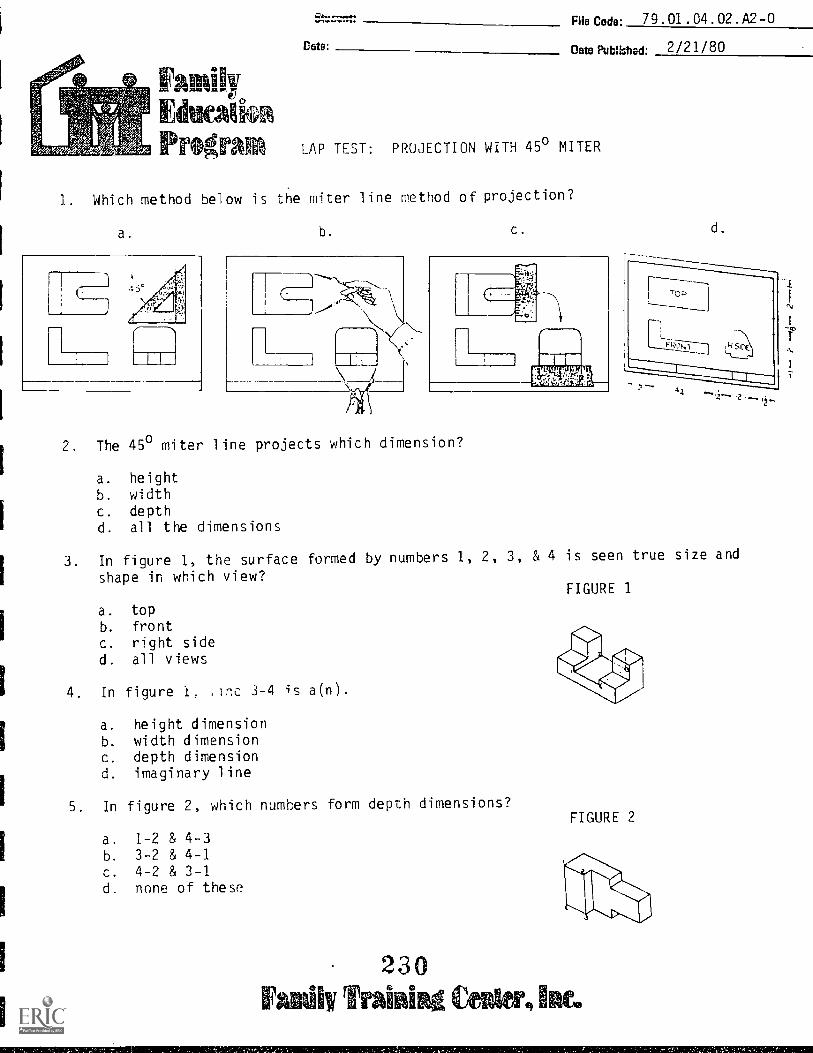
FamilyEducaika
1. Which
a.
Qemb%WY.
Date:
File Code: 79.01.04.02.A2-0
Date Published. 2/21/80
ram LAP TEST: PROJECTION WITH 45° MITER
method below is the miter line method of projection?
b. c. d.
2. The 45° miter line projects which
a. heightb. widthc. depthd. all the dimensions
dimension?
3. In figure 1, the surface formed by numbers 1, 2, 3, & 4 is seen true size and
shape in which view?
a. topb. frontc. right sided. all views
4. In figure 1, lot: 3-4 is a(n).
a. height dimensionb. width dimensionc. depth dimensiond. imaginary line
5. In figure 2, which numbers form depth dimensions?
a. 1-2 & 4-3b. 3-2 & 4-1c. 4-2 & 3-1d. none of these
230minim
FIGURE 1
FIGURE 2

LAP TEST ANSWER KEY
PROJECTION WITH 45° MITER
1. A
2. C
3. A
4. C
5. D
79.01.04.02.A2-02/21/80

EducatePr M!!"
File co de. 79.01.04. 03 .A2-0
Doe Pubiilhed: 1-30-79Revised: 11- 6-79
mink ackage
PERFORMANCE ACTIVITY: Pro_ ectipns Using a Dividers
Student:
Date:
OBJECTIVE:
Add missing views to various drawings by projecting from each view and transferingdimensions with a dividers.
EVALUATION PROCEDURE:
Instructor will examine drawings to see if all missing views have been added.Student must have all drawings correct.
RESOURCES:
Basic Technical Drawing, Chapter 6 and 7.Technical Drawing, Chapter 6.Drafting Rules and Principles, pages 20-21.Design Drafting, Chapter 7.Basic Drafting Tools: (see unit LEG)
PROCEDURE:
1 Read Resource(s).2 Number points on the given isometric sketch of each object.3 Using dividers and projection techniques, locate each point on the given
orthographic views: (Review page 152, Design Drafting).(Hint)Assign a number to each corner of tie object. Use the same number foreach point in both views. Note that the visible points nearestthe obs3rve 7.;T2 co be placed outside the object. (The invisiblepoints,or) points under (or behind) other points, lines or planes areplaced inside the object.
4. Project numbers from these views so that the projection lines intersect on themissing view, and complete the missing view by connecting these points.
5 Have instructor evaluate your work. Take the LAP test and pro,;eed to the
next LAP.
Principal Amthor4): S. Vosen, J. Wheatley
232
Vemaalhi 11,andises in%/3
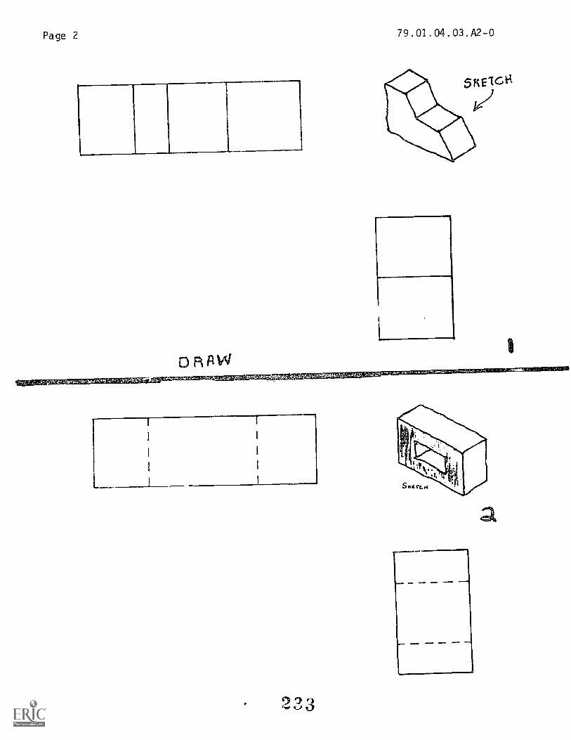
Page 2
ORAW
1
-g:''''"Miti;47,1,4qt".1.01r"M*R.2p9;'44.4-07,;,:i
79.01.04. 03.A2-0
a

Page 3
E\
79.01.04.03.A2-0
DRAW 34,111, 1,11.4, -re y
234

Page 4
1
3
79.01.04.03.A2-0
,===.5.VTICR=..4 11.1=51
23 5
. ow* MI. 11
=Ea m MM. IMIO
1 OM. M111 NNW NMI
_ :ieoltr ,...4lPtcSVI-Oei;-.4...,e0,../01.F.N-,

Page 5
,4".4" 4.4 L.
79.01.04.03.A2-0
-ts.r.et 71._Voemty,teK507./P.',,,V.4.-7.:.,7,70V;Nrrp0, Al', 0;7 7 ,',
:;
1.1;4s,F1de or
140t701 it I 47.4,
236

Family
Pr*
Re Code: 79.01.04.03. A2-0
Data Published: 2 21 80
LAP TEST: PROJECTIONS USING A DIVIDERS
1. Which drawing below shows the correct position for orthographic projection?
a. b. c. d.
2. Which view of Figure 1 will show a five sided shape?
a. topb. frontc. right sided. left side
3. If you were numbering ALL the points on Figure 1, how many would there be?
a. 11
b. 20
c. 16
d. 12
4. What dimension(s) can the dividers transfer?
a. heightb. widthc. dr-)th
d. all of these
FIGURE 1
5. If a surface is shown true size and shape in the top view, which view(s) will
show the surface as a line?
a. front
b. right sidec. both front and right sided. bottom
237

1. B
2. B
3. D
4. D
5. C
LAP TEST ANSWER KEY
PROJECTIONS USING A DIVIDERS
79.01.04.03.A2-02/21/80

File Code: 79 .01.04.04.A2-0
Family Published: 1-17-79
[AMIN% Revised: 11-13-79
Prog Learnin ctivity PackageStudent: le......11M.M,
Dote:
PERFORMANCE ACTIVITY: ....ilotching Missing Lines -- Visible and Hidden
OBJECTIVE:
Fill in missing 1 ines to complete the views for given objects.
EVALUATION PROCEDURE:
Using a prepared key, the instructor will examine drawings to see if the correct
isometric view has been drawn. All drawings must be correct.
RESOURCES:
Design Drafting, Chapter 7Basic Technical Drawing, Chapter 2, 6, and 7.
Basic Drafting Tools: (see unit LEG)
Drafting Furniture: (see unit LEG)
PROCEDURE:
I. Review the above resource(s).2. Sketch in missing lines on the following objects.
3. Upon completion of this LAP. proceed to LAP .05.
VISIBLE LINES
PrirtCi pig Author(s):
S. Vosen, J. Wheatley
ifri (2:!..A

Page 2
a
HIDDEN LINES
® 1
ASSORTED LINES
79.01.04.04.A2-0
z
(0.
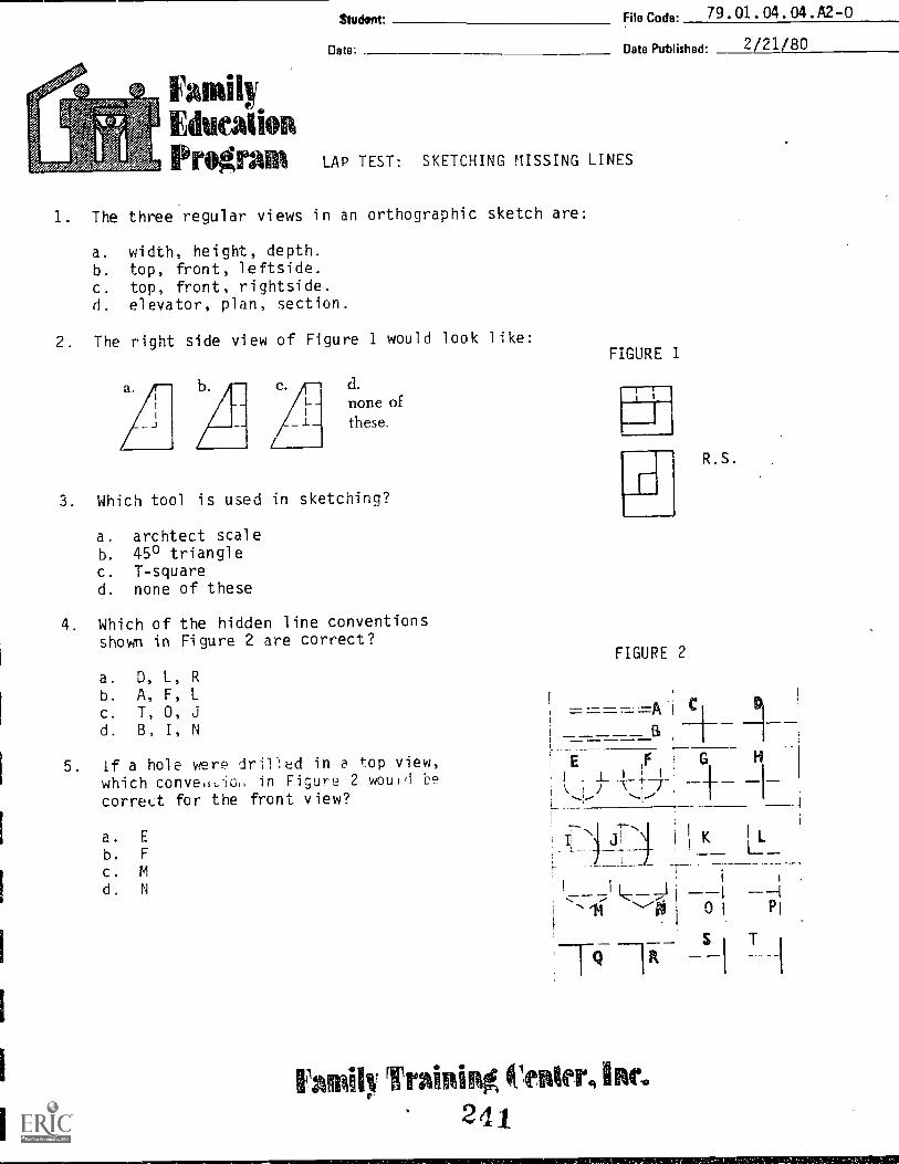
Student' File Coda: 79.01.04.04.A2-0
Date' Date Published: 2/21/80
FamilyEducationPrignillk LAP TEST: SKETCHING MISSING LINES
1. The three regular views in an orthographic sketch are:
a. width, height, depth.b. top, front, leftside.c. top, front, rightside.d. elevator, plan, section.
2. The right side view of Figure 1 would look like:
d.
none of
these.
3. Which tool is used in sketching?
a. archtect scaleb. 45° trianglec. T-squared. none of these
4. Which of the hidden line conventionsshown in Figure 2 are correct?
a. D, L, Rb. A, F, Lc. T, 0, Jd. B, I, N
FIGURE 1
Ir
R.S.
FIGURE 2
=====A
5. if a hole were drifled in a top view,which conved,io in Figure 2 would be l ; 1_ I ' 1
correct for the front view? L
a. E
b. F
c. M
d. N
J1 L_K I L
i_I -I
I j'V PI
Family Training Otienterg rocs
241
79.01.04.04.A2-02/21/80
LAP TEST ANSWER KEY
SKETCHING MISSING LINES
242
MarProgram Lear in9
File Code* 79.01.04.05.A2-0
Date Published: 1-17-79
Revised: 11-13-79
ctivity Package%stem
Date:
PERFORMANCE ACTIVITY: Isometric Sketch and Drawing ofRectangular Objects
OBJECTIVE:
To sketch and draw isometric views of various rectangular objects.
EVALUATION PROCEDURE:
Using a prepared key, the instructor will examine drawings to see if the correct
isometric view has been drawn. All drawings must be correct.
RESOURCES:
Basic Technical Drawing, Chapter 16 (paragraph 16.1 - 16.17)
Design Drafting, Chapter 9 (paragraph 9-1 through 9-18)
Basic Drafting Tools: (see unit LEG)Drafting Furniture: (see unit LEG)
PROCEDURE:
I. Read the above resource(s).
3. Choose a real object without curves from the objects available at the desk.
Using the attached sheet of isometric paper, make an isometric sketch of the
object (refer to Chapter 16 - 16.16, Basic Drawing).
3. Make isometric sketches of the four given orthographic objects.
4. Divide a sh size "A" drawing paper into four equal rectangles on each side.
Draw the following objects as isometric drawings: page 100, problems 1
through 8 in Basic Technical Drawing.
5. Have drawings evaluated by the instructor.
6. LAP test will be combined with and taken after completion of LAP .06.
Principal Auttior(1): S. Vosen, J. Wheatley

\s
4-
'\
\ \\
7-2\--
TvVA
-
\\
\\\
\\\\
_,,
\\\\-;\\
\\\\\/\'\\\\\
, -
\
\\Y\
\\.i___
,
,
\,
\
\
\
\
\
\
\
11111111,4
INIWAVabb.
A
WAN..
IOW1111W
.
N
\
iimmir114'

Page 3
5
7
5
6
79.01.04.05.A2-0
2.4 j

Page 4
111
2 3
246
79.01.04.05.A2-0

File Code: 79.01.04.06. A2-0
Detv Published: 1'30-79
EdRevised: 11-14-79
Program% Learning Activity PackageStudley
Date:
PERFORMANCE ACTIVITY: Isometric Drawings of Cylindrical Objectsand Objects with Major Holes and/or Curves
OBJECTIVE:
Given any object with major holes and/or curves, draw an isometric projectionof the object.
EVALUATION PROCEDURE;
Using a prepared key, the instructor will examine drawings to see if the correctisometric view has been drawn. All drawings must be correct.
RESOURCES:
Design Drafting, Chapter 9Basic Technical Drawing, Chapter 16Basic Drafting Tool s: (see unit LEG)Drafting Furniture: (see unit LEG)
PROCEDURE:
1. Read the resource(s). Hint: Pay close attention to the use of isometricell ipse templates.
2. Using size "B" drawing paper, draw objects #9, 11, and 13 on page 100 and objects#11, 13, and 15 on page 101 of your Basic Technical Drawing. Also on a size
"A" sheet of drawing paper draw object #1 on page 334 of your Basic Technical
Drawing.
3. Take the combined LAP test for .05 and .06.
4. Go on to the performance test.
Principal Author(s): S. Vosen, J. Wheatley
217111.116, lama Ilsk: mh At AD Await Ade 116

Studism. File Code. 79.01.04.05/.06
Date: Date Published: 2/25/80
hinnyEd tinProgri LAP TEST: ISOMETRIC SKETCHES
1. Which views are shown on isometric sketches?
a. topb. fror
c. righl. _Ade
d. all of these
2. Which instrument is used to draw circles in isometric?
a. compassb. French curvec. isometric templated. ellipse template
3. Which line(s) in Figure 1 will show true length in an isometric drawing?
a. 1-2
b. 3-5
c. 7-6
d. all of them.
FIGURE 1
4. The right, -,ert, and vertical axes or an isometric sketch are how many degrees
from each other?
a. 30°
b. 60°c. 90°
d. 120°
5. Which dimension is placed on the vertical axis?
a. widthb. depthc. heiahtd. all of these
Family TraiRiag Ceider,el,

79.01.04.05/.062/25/80
LAP TEST ANSWER KEY
ISOMETRIC SKETCHES
249

SUPPLEMENTAL MATERIAL FOR DRAFTING
DRAWING REPRODUCTION
79.01.05.00(Supplement 1)2-20-79
In general, there are three types of reproduction processes available to the drafts-
person. They are: 1) mechanical, 2) photochemical, and 3) special. Each general
process has several specific processes. Some of the more common under each heading
is: 1) mimeograph, lithograph and typing, 2) blueprint, Van Dyke, Diazo, and photo-
graph, 3) Thermofax, and Xerograph. The specific processes we are most interested
in are Blueprinting and Diazo printing.
Blueprinting: Blueprinting is the oldest process and was at one time
the only reproduction method besides tracing and hand copying. However,
it is being replaced. (For further information refer to Basic Tech-
nical Drawing, page 106, paragraph 7.4).
Diazo Printing: Diazo printing (or whiteprints) is replacing the older
methods. This is the process we use in the class. The Diazo print is
made on sensitized paper by first exposing the paper under U-V and then
developing it with ammonia fumes. (For further information refer to
Basic Technical Drawing, page 107, paragraph 7.5).
In blueprinting, the background is a dark blue and the lines appear white. With
Diazo, the background is white and the lines may be many colors. Some common colors
are blue, black, brown, yellow, etc. With both processes, the original drawing must
be made on a translucent material (i.e., vellum or mylar). The drawing itself may
be done in either lead or ink.
Diazo is a two-step process. In the first step, the sensitized paper must be ex-
posed. The paper has a coating, which when exposed to U-V light, is broken down
and becomes nonreactive. The U-V light is passed through the translucent drawing
exposing all but the portions covered by the lead or ink lines. There are four
variables which affect th'e exposure. The type of Diazo paper, the weight of the
line, the length of exposure, and the type of original.
Diazo paper comes in an assortment of speeds. From normal (speed 5) through super
fast (speed 14). The faster paper has a more reactive sensitive coating and takes
less U-V light to be exposed.
The weight of the line determines the amount of light which passes through the line.
The heavier the line, the less light passed through and the more coating left on the
paper. Naturally, ink will allow less light to pass through than lead.
The length of exposure is controlled by the speed setting on the expediter. There
are two level settings and speed settings from A through Low. The slower the speed
setting, the longer the length of exposure.
Originals may be drawn on several kinds of material. It may be on common bond paper,
linen, vellum, or plastic film. The U-V light penetrates each material differently.
250
Page 2 79.01.05.00(Supplement 1)
The second step in the Diazo process is to develop the exposed sensitized paper.The paper is passed through a machine which produces ammonia vapors. These vaporsturn the reactive coating a different color then the exposed background. Thelength of time in the developer and the strength of the ammonia vapors determinethe darkness of the developed lines. The machine used in this class is not adjust-able so the number of times the paper is passed through it controls darkness. Othermachines have speed controls.
Diazo printing is used for several different jobs. The most common is to reproduceone original so that several people can have copies. Also, copies are made so thatthe original will not be damaged during use. If only a few copies are needed, (1-20)they may be reproduced from the original. If more (20-200) are needed, a Sepia printis made from the original and the required copies are reproduced from the Sepia copy.Sometimes information recorded on common bond (white) paper is needed. Using extrafast paper, the Diazo process can make copies directly from the bond paper.
251

Page 3 79.01.05.00(Supplement 1)
USE OF THE TWO-STEP DIAZO REPRODUCTION SYSTEM(Rotolite Machine)
Follow the steps listed below:
1. Switch on the developer and then the ammonia pump. Let them run ten minutes
before using the machine.
2. Get the correct size of Diazo paper from the cabinets. If necessary, but it
to size on the paper cutter.
3. Switch on the expeditre and adjust the speed according to the attached chart.
4. Place the original face up on the green side of the Diazo paper. Holding both
pieces with the face of the original toward you, feed it into the expediter.
5. Once the print is exposed, remove the original from the Diazo paper. Holding
the Diazo paper face toward you, feed it into the developer.
6. Shut the expediter and the pump off. Leave the developer motor running forfive minutes to clear the ammonia from the machine.
USE OF THE DIAZIT DART
Procedure:
1. Switch the machine on and wait until the U-V light stops flickering.
2. Set the speed control dial to the proper speed (see attached chart).
3. Place the original face up on the green side of the Diazo paper. Holding
both oieces with the face of the original up toward you, feed them acrossthe feed bar until the machine picks them up.
4. As both pieces come out of the machine, separate them and feed the Diazopaper into the developer.
5. When the print is developed, turn the machine off.

Page 4 SUGGESTED SETTINGS FOR THE ROTOLITE BLUEPRINT MACHINE* 79,01.05.00
(Supplement' 1)
MACHINE
WARM UP
PAPER
SPEED**
ORIGINAL
COPY
LINE
WEIGHT
ACTINIC LIGHT EXPOSURE
ROLLER SPEEDS A-0***
10 minutes 5 Sepia Vellum
Vellum
Mylar
Mylar
Lead
Ink
Lead
Ink
Low -- E
Low -- H
Low G
Low I
10 minutes 7 Vellum
Vellum
Mylar
Mylar
Lead
Ink
Lead
Ink
High -- J
High -- Low
High -- H
High -- K
10 minutes 9 (Extra Fast Standard White
Vellum
Vellum
Mylar
Mylar
Lead
Lead
Ink
Lead
Ink
Low -- J
High -- I
High -- K
High -- G
High -- J
10 minutes 10 Standard White
Vellum
Vellum
Mylar
Mylar
Lead
Lead
Ink
Lead
Ink
Low -- J
High -- H
High -- J
High -- F
High -- I
*This machine uses a dry-ammonia vapor developing process.
**Paper speeds from 5 - 14 -- (slow, fast, extra fast, super fast) -- can be obtained.
(We use speeds 5, 7, 9, 10:
9 &
5
7
10
-- for corrections only.
-- slowest speed, more background print.
-- fastest speeds, cleaner background print.
***Roller speeds: A -- fastest
0 -- slowest
253254

-rage a-- VVUULV166, VLIIAMAV
(Supplement 1)
Diazo Type and Speed** Original Medium Line Medium Machine Speed**k
#5 Sepia or Tuf-TexVellum Lead 4
Vellum Ink 3
Mylar Lead 4
Mylar Ink 3
#7 DiazoVellum Lead 6-7
Vellum Ink 5
Mylar Lead 6-7
Mylar Ink 5
#9 DiazoBond Paper Lead/Ink 4
Vellum Lead 7
Vellum Ink 6
Mylar Lead 7
Mylar Ink 6
#10 DiazoBond Paper Lead/Ink 5
Vellum Lead 8
Vellum Ink 7
Mylar Lead 8
Mylar Ink 7
*WARNING: This machine uses 26° baume, full strength, aqueous ammonia as a developing agent. Aqueous ammonia and its
vapors have been identified as toxic and could cause serious personal injury if handled or used incorrectly. Subparts
I and Z of part 1910, OccupationalSafety and Health Standards, chapter XVII of Title 29 of the Code of Federal Regu-
lations, as amended, establishes procedures for the handling and storage of ammonia as well as exposure levels for
ammonia vapors. It is each employer's responsibility to comply with these regulations. Please have your employees,
as appropriate, become familiar with these regulations and be sure that this machine is used and operated in accord-
ance with them.
**Paper speeds from 5-14 -. (slow, fast, extra fast, super fast) -- can be obtained.
We use speeds 5, 7, 9, 10: 5 -- for corrections only.
7 - slowest speed, more background print.
9 & 10 fastest speed, cleaner background print.
NOTE: When combining paper and roller speeds, faster paper requires less time to expose; therefore, use a faster
roller setting.Slower paper requires more time to expose; therefore, use a slower roller setting.
***Machine Speeds: 0 -- Slowest more light exposure results in a lighter print with less background print).
21 -- Fastest (less light exposure, causes a darker print, but more background print may result).
255

MountainPlains EducaUonEconomic Llevelopment
Program. Inc.
Glasgow AFB. Montana 492
File Code: 79.01.05.01.A2-1
Date Published: 12-16-75
Revised: 7-31-78
1@ovuo5mg Empcntgalag @aqc`kg
UNIT: MULTIVIEW PROJECTIONS: TECHNIQUES AND APPLICATIONS
RATIONALE:
In manufacturing, it is often necessary to have drawings of the object which clearly
show surfaces in their true size and shape. The common method of doing this is called
orthographic projection or multiview projection. Also, as each person in the manufac-turing process needs a drawing of the object, methods were devised to reproduce thosedrawings. In this unit you will learn to provide a multiview drawing of an object andthe copies needed.
PREREQUISITES:
Unit: 79.01.04 Shape Description
OBJECTIVES:
Draw an orthographic drawing of a given illustration using appropriate tools, procedures,
techniques, and applications.
Identify terms, definitions and characteristics of orthographic drawings.
Identify terms and characteristics of various reproduction methods and use the Diazo
process properly.
RESOURCES:
Printed Materials
Basic Technical Dr-.4nn. Spencer and 1)rydon, Macmillan Company, New York.
Engineerino Drawing and Graphic Technology. French and Vierck, Eleventh Elition,
McGraw-Hill Book Company, New York.Mechanical Drawing. French and Svenson, Webster Division, McGraw-Hill Book Company,
New York.Technical Drawing. Sixth Edition, Gieseche, Mitchell, Spencer and Hill, Macmillan
Company, New York.
Equipment
Basic Drafting Tools: As listed in the course LEG.
Principal Author(s): C. Wetterling, J. Wheatley
257
Page 2 79.01.05.00.A2-1
Resources: (continued)
Diazo Reproduction SystemDrafting Furniture: stool, drafting
Wle, drafting (with T-square, parallel rule and/or draftingmachine).
GENERAL INSTRUCTIONS:
This unit consists of four Learning Activity Packages (LAPs). Each LAP will providespecific information for completion of a learning activity.
The general procedure for this unit is as follows:
1. Read the first assigned Learning Activity Package (LAP).2. Begin and complete the first assigned LAP.3. Keep the drawing mounted on the board until it has been checked and
approved by the instructor.4. If there is a LAP test indicated on the LAP sheet, take the LAP test
before going on to the next LAP.5. Proceed to and complete the next assigned LAP in the unit.5. Complete all required LAPs for the unit by following Steps 3 and 4.7. Take the unit tests as described in the Unit LEG "Evaluation Procedures".8. Proceed to the next assigned unit.
PERFORMANCE ACTIVITIES:
.01 Multiview Projection of a Bearing Cap
.02 Multiview P:ojection of a Guide Base
.03 Multiview Projection of a Guide
.04 Multiview Projection of a Wedge Base
EVALUATION PROCEDURE:
When post 4-c!sting:
1. The student takes a multiple-choice post test and turns it in for correction.
2. The student takes a unit performance test. Successful unit completion is meetingthe listed criteria for the performance test.
FOLLOW-THROUGH:
The skill of drawing multiview projection will be used again in future units and will
be monitored when the opportunity arises.
The drawings in this unit must all have the title block and boarder properly inked. All
title headings should be in Leroyed in ink and the rest freehanded in pencil. In addi-
tion, each drawing must have the three views (top, front and right side) properly posi-
tioned and correctly spaced. Use 12" x 18" drawing paper.
Begin the first assigned Learning Activity Package (LAP).
258

ountain-Plains Education &onomic Development
Program, Inc.
Glasgow AFB. Mon 23111W7'`
1. Multiview means:
Student. File Code: 79 01 nS no. A2-2(. 01-.04)
Date: Dar Published: 6/20/74
UNIT/LAP PRETEST: MULTIVIEW PROJECTION
a. one view.b. two views.c. two or more views.d. three views.
2. The top view is:
a. over the front view.b. over the side view.c. below the front view.d. below the side view.
3. In orthographic projection, the projectors are:
a. at a 45 degree angle to the plane of projection.b. parallel to the plane of projection.c. perpendicular to the plane of projection.d. at a 30 degree angle to the plane of projection.
4. The rear, left side, and front views are:
a. aligned vertically and are the same height.b. aligned horizorally and are the same width.c. alicr.-r! horizontally and are the same height.d. aligned vertically and are the same width.
5. Depth dimensions in the top and side views:
a. must correspond point-for-point.b. must correspond in the left side but not the right side.c. must correspond in the right side but not the left side.d. do not correspond.
259

Page 2 79.01 , 05.,00.
(.01-.04)
6. A removed view is a complete or partial view that is:
a. not in direct projection with any other view.b. left out of the regular projection.c. drawn on another sheet of paper.d. never drawn on a working drawing.
7. If a series of parallel planes is intersected by another plane, theresulting opposite angles of intersection will be:
a. equal
b. perpendicularc. parallel.d. unequal.
8. A blind hole Is one with a specified:
a. arc length.b. radius.c. diameter.d. depth.
9. A rounded interior corner is called a:
a. fillet.b. round.c. sharp corner.d. rough corner.
10. A ruoncied corr,c3r is called a:
a. round.b. fillet.c. sharp corner.d. rough corner.
26 0
79.01.05.00 . A2-2(.01-.04)
UNIT/LAP PRETEST ANSWER KEY: MULTIVIEW PROJECTION
1. C2. A3. C4. C5. A6. A7. A8, D9. A
10. A
261
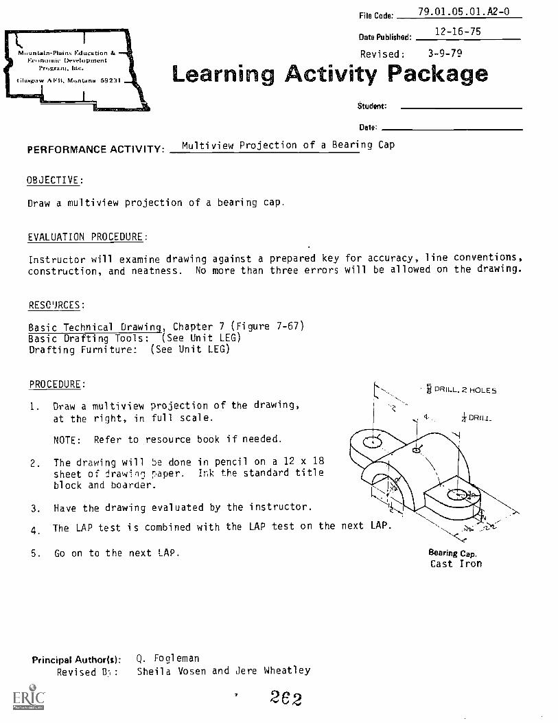
Mguntaln-Pluin% gducationDrvelopment
l`mgram, Inc.
(3upKow AF11. Montana 59231
File Cade' 79.01.05.01.A2-0
Date Published'12-16-75
Revised: 3-9-79
Learning Activity PackageStudent:
Date:
PERFORMANCE ACTIVITY: Multi view Projection of a Bearing Cap
OBJECTIVE:
Draw a multiview projection of a bearing cap.
EVALUATION PROCEDURE:
Instructor will examine drawing against a prepared key for accuracy, line conventions,
construction, and neatness. No more than three errors will be allowed on the drawing.
RESO'JRCES:
Basic Technical Drawing, Chapter 7 (Figure 7-67)Basic Drafting Tools: (See Unit LEG)Drafting Furniture: (See Unit LEG)
PROCEDURE:
1. Draw a multiview projection of the drawing,
at the right, in full scale. DR111_
NOTE: Refer to resource book if needed.
DRILL. 2 HOLES
2. The drawing will 5e done in pencil on a 12 x 18sheet of drawn' paper. Ink the standard titleblock and boarder.
3. Have the drawing evaluated by the instructor.
4. The LAP test is combined with the LAP test on the next LAP.
5. Go on to the next LAP.
Principal Author(s): Q. Fogl eman
Revised 81: Sheila Vosen and Jere Wheatley
2 6 2
Bearing Cap.Cast Iron

Stodent. File Code:79.01.05.01/02:C2-2
Data: Date Published: 3-8-79
EthwatiosINM04114111 LAP TEST: MULTIVIEW PROJECTION -- (combined test)
1. A depth dimension is found on which of the following views?
a. top, front and R.S.b. L.S., front and R.S.
c. R.S., top and L.S.d. front, top and back
2. Given the following figure, which one of the R.S. views below is correct?
A
POI NT OFTANGENCY
B
3. On the figure below, what points are shown of the R.S. view?
a. 1, 2, 3, and 4b. 1, 2, 3, 4, 5, and 6c. 1, 3, 9, 8, and 5d. All of them.
4. The L.O.S. (Linc of sight) in multivi-.w projection isviewed.
a. perpendicular c. at a 60° angle
b. parallel d. equal
5. Which of the below is not good pencil technique?
a. dark construction lines c. sharp, clean cornersb. dense, dark object lines d. correct line thickness and dash lengths
to the surface being
Family Train! Craw., bit63

COMBINED LAP TEST - MULTIVIEW PROJECTION
t
264
79.01.05.01/02 C2-2

Mountain-Plains Education &Economic Development
Program, Inc.
(illiagow APB, Montana 69231
File Code:79.01.05.02.A2-0
Date Published12-16-75
Revised: 3-6-79
Learning Activity PackageStudent:
Date
PERFORMANCE ACTIVITYMultiview Projection of a Guide Base
OBJECTIVE:
Draw a multiview projection of a guide base.
EVALUATION PROCEDURE:
Instructor will examine drawing against a prepared key for accuracy, line conventions,construction, and neatness. No more than three errors will be allowed on the drawing.
RESOURCES:
Basic Technical Drawing, Chapter 7 (Figure 7-47).Basic Drafting Tools: (See Unit LEG)Drafting Furniture: (See Unit LEG)
PROCEDURE:
1. Read the above resource(s).2. Draw a multiview projection of the
drawing on this sheet.3. The drawing will be done in pencil
on a sheet of 12 x 18 drawing paper. Ink wthe standard title block and boarder.
4. Have the 'nstructer evaluate the drawing.5. Take the CCA,Li LAP 1",:c.t.
6. Proceed to the next LAP.
itliCD
45°
16
2.000 REAM(Through)
, I.. ,
J-6'
CRS - 1 REQD1
ALL OVER -- 3/4 DRILL -Thru14 CBORE - 14 DEEP
Guide Base. Draw 1/2 size
Principal Author(s): C. Wetterling, S. Vosen, J. Wheatley
26

Mountain-Plains Education &Econowle Devriopment
Program.
(;luagow AIMS, Montana 59231 Learning
79.01.05.03.A2-0File Cade
Date Published:12-16-75
Revised: 3-9-79
ativity Package
PERFORMANCE ACTIVITY: Multiview Projection of a Guide
OBJECTIVE:
Studaiit:
Date:
Draw a multiview projection of a guide and reproduce a Diazo copy.
EVALUATION PROCEDURE:
Instructor will examine the Diazo copy against a prepared key for accuracy, line con-vention, construction, neatness, and print clarity. No more than three errors will be
allowed on the drawing.
RESOURCES:
Basic Technical Drawing, Chapter 7 (Fig. 7-65)Supplemental material: Drawing reproductionBas,c Drafting Tools: (See Unit LEG)Drafting Furniture: (See Unit LEG)
PROCEDURE:
1. Draw a multiview projection of the drawing indicated on this sheet. The drawing
will be done in pencil on 12 x 18 first. NOTE: Refer to Chapter 7 in the re-
source book if needed.
2. Trace thc drayin; ink on a sheet of 12 x 18 vellum. Use the following ink pens for
correct line weight: Center lines -- #00; Hidden lines -- #0, and Object lines -- #1.
3. Use the Diazo machine and reproduce a copy to be evaluated by the instructor.
(Refer to reproduction supplement).
4. The LAP test is combined with the next LAP test.
5. Proceed to next LAP.
Principal Author(s): Q. Fogleman, S. Vosen, and J. Wheatley
2e6
or ILL_\ DRILL2 HOLESr
Guide
H.R.S.

MountainPlains F.thietitionEconomic Development
Nogram,Inc.
GluNgo w A Montana 59231
79.01.05.04.A2-0File Code:
Date Published-12/16/75
Revised: 3-7-79
Learning ctivity PackageStudent:
Date:
PERFORMANCE ACTIVITY:Multiview Projection of a Wedge Base
OBJECTIVE:
Draw a multiview projection of a wedge base and reproduce a Diazo copy.
EVALUATION PROCEDURE:
Instructor will examine the Diazo copy against a prepared key for accuracy, line conven-
tion, construction, neatness and print clarity. No more than three errors will be
al lowed on the drawing.
RESOURCES:
Basic Technical Drawing, Chapter 7 and 8 (Figure 7-62)
Supplemental material: Drawing Reproduction
Basic Drafting Tools: (See Unit LEG)
Drafting Furniture: (See Unit LEG)
PROCEDURE:
1. Draw a multiview projection of the drawingindicated on this sheet. The drawing willbe done in pencil on a 12 x 18 sheet first.
NOTE: RLFPr resource hook if needed.
2. Obtain a sheet of vellum, overlay your draw-ing and make an ink copy including the title blockand boarder. Use the line weights given in pre-vious LAP.
3. Use the Di azo machine and reproduce a copy to beevaluated by the instructor.
Take the combined LAP Test.
5. Proceed to the Performance Test.
Principal Author(s): C. Wetterling, S. Vosen and J. Wheatley
2C7
11,fri
, '
[1.; DFtll LHOLES
Wedge Base.*
CRS

Student:
Date:
FamilyEthwatise
Fib Code:79.01.05.03/04:C2-2
Otto Published: 3-8-79
Pram LAP TEST: REPRODUCTION TECHNIQUES -- (combined test)
1. The reproduction process used in this class is:
a. blueprintb. Thermofax
c. Diazod. Xerox
2. If a print has too much background, you must:
a. speed up the machine c. use slower paper
b. slow down the machine d. print darker
3. When inking a drawing for reproduction, what is the correct order of lines?
a. horizontal, vertical, inclined, curved
b. vertical, horizontal, inclined, curved
c. inclined, horizontal, curved, verticald. curved, horizontal, vertical, inclined
4. The originals drawn in these LAP's were inked on:
a. Vellumb. Mylar
c. Bond paperd. Drawing paper
5. Which paper takes the longest exposure time?
a. speed 5 Sepiab. speed 7 Bluline
c. speed 9 Blaclined. speed 10 Bluline
iy Traini (Unger, firz26

79.01.05.03/.04 C2-2
COMBINED LAP TEST REPRODUCTION TECHNIQUES
269

ountain-PIAMs Education Se'conomle Development
Program. Mc.
...ow A F13. Monank- 59231
&Wont File Code:79.01.05.00.A1-5
Date: Date Published: 11/06/74Date Revised: B/01/78
Family Pay # Sex: M F (Circle One)
UNIT PERFORMANCE TEST: muITTvIFW PROJECTION
OBJECTIVE 1:
Given an illustration of a machined object, the student will be able to draw an ortho-
graphic drawing of it with three views that are properly centered, neat, and accurate
to the given dimensions.
OBJECTIVE 2:
The student will be able to properly ink the completed drawings.
OBJECTIVE 3:
Reproduce a Diazo copy of the drawing.
OBJECTIVE 4:
The student will be able to draw lines that are:
a. neatb. properly drawnc. weighted to appropriate contrasts.
TASK:
The student will make a Multiview Projection of the following object, and reproduce a
Diazo copy.
Holder Base.*
270

Page 2 79.01.05.00.A1-5
ASSIGNMENT:
Draw the holder base found in Basic Technical Drawinl, page 129. Use 12 x 18 drawingpaper and trace the object in ink on vellum. Make a Diazo print.
CONDITIONS:
The drawing is to be completed in a typical drafting room setting, using the completefacilities.
The student will not be able to use the instructor(s) or other students as a resource.
RESOURCES: (See Unit LEG).
At least one of the following:
Technical Drawing, Giesecke/Mitchell/Spencer/HillMechanical Drawing, French and SvensonEnginerring Drawing and Graphic Teemology, French and VierckBasic Technical Drawing, Spencer and Drydon
Blue/Black Line Printer.
271
Page
untaln-Plains Education &onornlc Development
iGlaagow AFB. 231111 \\1,'.
Program. Inc.
Student. Fite Code: 79.01.05.00.A1-5
Date: Date Published: 11/6/74Revised: 8-01-78
Family Pay Number: Sex: M F (Circle 1)
PERFORMANCE CHECKLIST:
OVERALL PERFORMANCE: Satisfactory Unsatisfactory
CRITERIONMet Not Met
Objective 1:
1. Complete object is drawn.
All lines specified in the assignmentCriterion: are drawn.
2. Drawing consists of three views which are properly
positioned
Criterion: Object lines can be accurately projected from one view to another.
Mechanical Drawing, pp. 87-91
Ob'ective 2:
3. Coete drawing is inked fly
Criterion: (ASA Standards), Technical Drawing, p. 64. Boarder and title block
lines (pen #2--LeRoy Template #175), object lines (pen #1), hidden
lines (pen #0), Center lines open #00)
_ .
Objective 3:
4. Drawing is clean and neat ____ _ _ ______ ___
Criterion: (ASA Standards), Technical Drawing, p. 12-22
272

Page 4
(Checklist continued)
79.01.05.00.A1.5
CRITERIONMet Not Met
5. Drawing is centered correctly.1
Criterion: (ASA Standards), Technical Drawing, p. 167
6. Total drawing is accurate to given dimensions.
Criterion: Plus or minus 1/64"; plus or minus 10
Objective 4:
7. Hidden lines are neat and properly drawn.
Criterion: (ASA Standards), Technical Drawing, p. 14S.
8. Visible lines are neat and properly drawn.
Criterion: (ASA Standards), Technical Drawing, p. 20
9. Hidden lines are of appropriate contrast in relation to
the other lines.
Criterion: (ASA Standards), Technical Drawing, p. 20
10. Visible lines are of appropriate contrast in relation to
the other lines.
Criterion: (ASA Standards), Technical Drawing, p. 20
11. The drawing 1 .r.ipleted in t;-,e -necified time limit.
Criterion: Not to exceed 5 hours.
The student must meet criterion on 8 line items to obtain an
overall score of satisfactory.
273

I.,,,ottntaln-Plains Education &onomic Development
Program, inc.
/1, U1sjgow AFB. Moraarie 69231
79.01.05.00.82-2Student: File Code:
Date: Date Published.
Revised:
UNIT POST TEST: MULTIVIEW PROJECTION
1. In American Standard projection there can be as many as:
a. 3 principle viewsb. 6 principle viewsc. 1 principle viewd. any number of principle views.
2. The top, front, and bottom views are:
a. aligned horizontally and are the same heightb. aligned vertically and are the same height.c. aligned horizontally and are the sane width.d. aligned vertically and are the same width.
6-20-74
8-14-78
3. If two lines are parallel in space, their projections are parallel in:
a. the top view only.b. any view.c. the front view only.d. the end view only.
4. A line that is parallel to a plane of projection will be shown true size
on:
a. the plane of projection to which it makes a 60 degree angle.
b. the plane of projection to which it is perpendicular.c. the plane of projection to which it makes a 45 degree angle.d. the plane of Projection to which it is parallel.
5. Projection iq technical name for a:
a. station point.b. line between the views.c. complete working drawing.d. view.
6. The process of drawing reproduction used in this course is called:
a. blue printing.b. Diazo printing.c. lithograph printingd. Xerox printing.
274

Page 2 79.01.05.00.B2-2
7. The slower the original is passed through the exposure:
a. the darker the lines will be.b. the more background print there will be.c. the less background print there will be.d. the clearer the lettering will be.
8. The most common materials for originals are:
a. plastic film and transparent paper.b. classic drawing paper and blue line.c. clear paper and linen.d. bond paper and Mylar.
9. Depth dimensions are projected:
a. from the top to the front view.b. from the right side view to the front view.c. from the right side view to the top view.
d. from tne top view to the back view.
10. To view a surface true size, your line of sight must be:
a. perpendicular to the surface.b. parallel to the surface.c. from the front view.d. from the right side.
275

79.01.05.00.82-2
UNIT POST TEST ANSWER KEY: MULTIVIEW PROJECTION
I. B
2. D
3. B
4. D
5.
6. B
7. f;
8. A
9. C
10. A

RATIONALE:
79.01.06.00
ant*File Code:
11-17-78Oat& Publithed:
Education
ProgrIm R®agootiK. Eap@alGiuoc® @aidcl®UNIT: DIMENSIONING
Dimensions are just as important to working drawings as the views of the object. Theyclearly state the correct size to which the object must be made. It is therefore im-portant that you learn how to correctly dimension drawings which tell the craftsmanhow to make the object. Different manufacturing processes require specific differ-ences in dimensioning.
PREREQUISITES:
Unit: 79.01.05 -- Multiview Projection
OBJECTIVES:
The objective of this unit is to give the student the opportunity to demonstrate abilityto correctly dimension orthographic drawings of four manufacturing processes.
Identify characteristics of correctly dimensioned orthographic drawings.
Draw a lead and vellum original which can be clearly reproduced by the Diazo Process.
RESOURCES:Printed Materials
Basic Technical Drawing. Spencer and Drydon, MacMillan Company, New York.Engineering Drawing and Graphic Technology. French and Vierck, Eleventh Edition,
McGraw-Hill Book Company, New York.Technical Drawing. Sixth Edition, Gieseche, Mitchell, Spencer and Hill, MacMillan
Company, New York.Handbook. of Drafting Rules and Principles. First Edition, Nelson, McKnight and McKnight,
Illinois.
,..dulu/Visuals
Size Description, Drafting Series, Doubleday ,Multimedia.
EAyipment
Basic Drafting Tools: As listed in Course [Fr.
Principal Author(s): S. Vosen, J. Wheatley, anti C. Wetterl ing
277Cfram, SRC.

Page 2 79.01.06.00
RESOURCES: Equipment (continued)
Blue/Black line printerDrafting Furniture: stool, drafting
table, drafting (with T-square, parallel rule and/or draftingmachine)
Player, audio cassetteProjector, filmstrip
GENERAL INSTRUCTIONS:
This unit consists of four Learning Activity Packages (LAPs). Each LAD will providespecific information for completion of a learning activity.
The general procedure for this unit is as follows:
1. Read the first assigned Learning Activity Package (LAP).2. Begin and complete the first assigned LAP. NOTE: Make drawing on tracing paper
with pencil.3. Make a blueprint copy of the drawing and have it evaluated by the instructor.4. When the blueprint is satisfactory, proceed to and complete the next assigned
LAP in the unit.5. Complete all required LAPs for the unit by following Steps 3 and 4.6. Take the unit tests as described in the Unit LEG "Evaluation Procedures".7. Proceed to the next assigned unit.
PERFORMANCE ACTIVITIES:
.01 Dimensioning a Safety Key
.02 Dimensioning a Door Bearing
.03 Dimensioning a Centering Wedge
.04 Dimensioning a Holder Clip
EVALUATION PROCEDURE:
When post testing:
1. The student :tikes a .lultiple-choice post test and turns it in for correction.
2. The student taKes a unit performance test. Successful unit completion ismeeting the listed criteria for the performance test.
FOLLOW-THROUGH:
Dimensioning will be used and evaluated on all drawings completed fur the rest ofthe course.
The drawings in this unit will all be done un 12" x 18" tracing paper (vellum). Ink
the boarder and title blocks using proper format. Do all of the drawing and dimension-
ing in pencil. After completing each drawing, make a blueprint copy of it. Do not
make a second copy unless instructed to do so.
Begin the first assigned Learning Activity Package (LAP).
278

ountain - Plains Education &onomic Development
Program. Inc.
Glasgow AFB. Mona` 69231
Student: File Code: ___79 . 01 . 06. 00 . A2-2
Date:( . 01 . 04 )
Date Published' 6/20/74
UNIT/LAP PRETEST: DIMENSIONING
1. The way to dimension a hole is:
2. The system of writing dimensions shown below is the
a. only system used.b. the aligned system.c. bottom system.d. unidirectional system.
3. If space is limited, the correct way to indicate dimensior-1.7, is:
a. 9J1.1-r b.
_L
FC. d. All are correct.

Page 2 79.01.06.00. A2-2(.01-.04)
Uj
1
4, The location dimensions shown above are:
a. A, C, and B.b. A and C.c. B and F.d. all dimensions are location dimensions.
5. The size dimensions shown above are:
a. 0, D, E, and F,b. D, E, and F.c. B, D, E, F, and G.d. all dimensions are size dimensions.
6. Drawings should be made to scale, and the scale should be indicated:
a. cr cdpject.b. in the title block.c. outside the border line.d. only when smaller than full scale.
7. Dimensions are given in the form of:
a. linear distances, angles, or notes.b. fractions only.c. decimals only.d. arrowheads.
2:tio
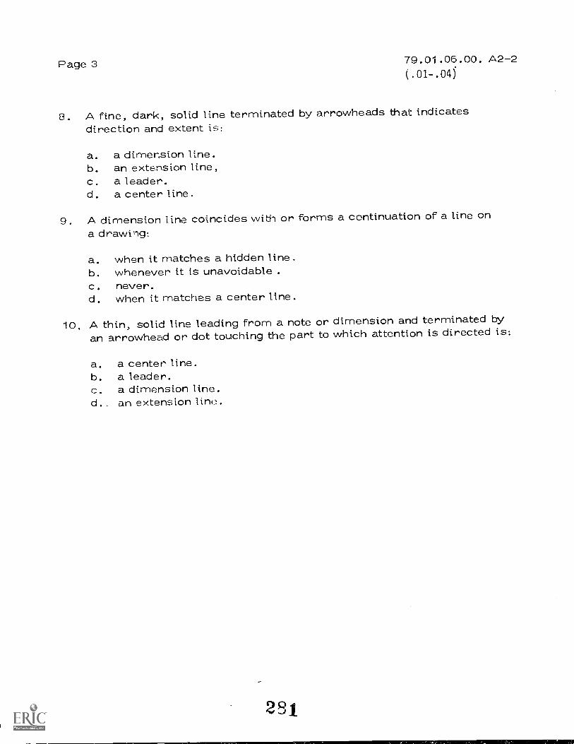
Page 3 79.01.06.00. A2-2(.01-.04)
8. A fine, dark, solid line terminated by arrowheads that indicatesdirection and extent is:
a. a dimension line.b. an extension line,c. a leader.d. a center line.
9. A dimension line coincides with or forms a continuation of a line ona drawing:
a. when it matches a hidden line.b. whenever it is unavoidable .c. never.d. when it matches a center line.
10. A thin, solid line leading from a note or dimension and terminated byan arrowhead or dot touching the part to which attention is directed is:
a. a center line.b. a leader.c. a dimension line.d.. an extension line.
281
UNIT/LAP PRETEST ANSWER KEY: DIMENSIONING
1 .
2. D3. D4. B
5. C
6. B7.8. A9 . C
10. B
2 S 2
79.01.06.00 .A2-2(.01-.04)

Eved FEducation
79.01.06.01File Code.
mita Publishod:11-17-78
Learnmq ta,--Aittivrt
PERFORMANCE ACTIViTY: Dimensioning a Safety Key
Studimt:
Date:
ackage
OBJECTIVE:
Draw and dimension an orthographic projection of an object machined from stock.
EVALUATION PROCEDURE:
Instructor will examine Diazo Prints for neatness, accuracy, clarity, line work andproper dimensioning.
RESOURCES:
Drafting Rules and Principles -- Chapter 3Basic Technical Drawing -- Chapters 9 and 10.Technical Drawing -- Chapters 10 and 11.Engineering Drawing and Graphic Technology -- Chapters 11 and 12.1 'P
Basic Drafting Tools: (See Unit LEGIDrafting Furniture: (See Unit LEG)Blue/Black Line PrinterFilmstrip ProjectorAudio Cassette PlayerSize Description -- Drafting Series. -
50 DIA
PROCEDURE:
I. Read the above resource(s).
2. View filmstrip on Si _r escrintion.
C PI RFOD
Safety Key
3. Draw an dimension an orthograpo projection of the object shown on a 12" x 18"sheet of drawing paper.
4. Trace the object on vellum using lead and an inked border.
5. Have the instructor evaluate a blueprint copy of the completed drawing.
6. Take the LAP test for this LAP and proceed to LAP 02.
PencipailAuthorOW S. Vosen , J. Wheatley, C. Wetterl i ng
293BilettAsidur 11461dPIP_
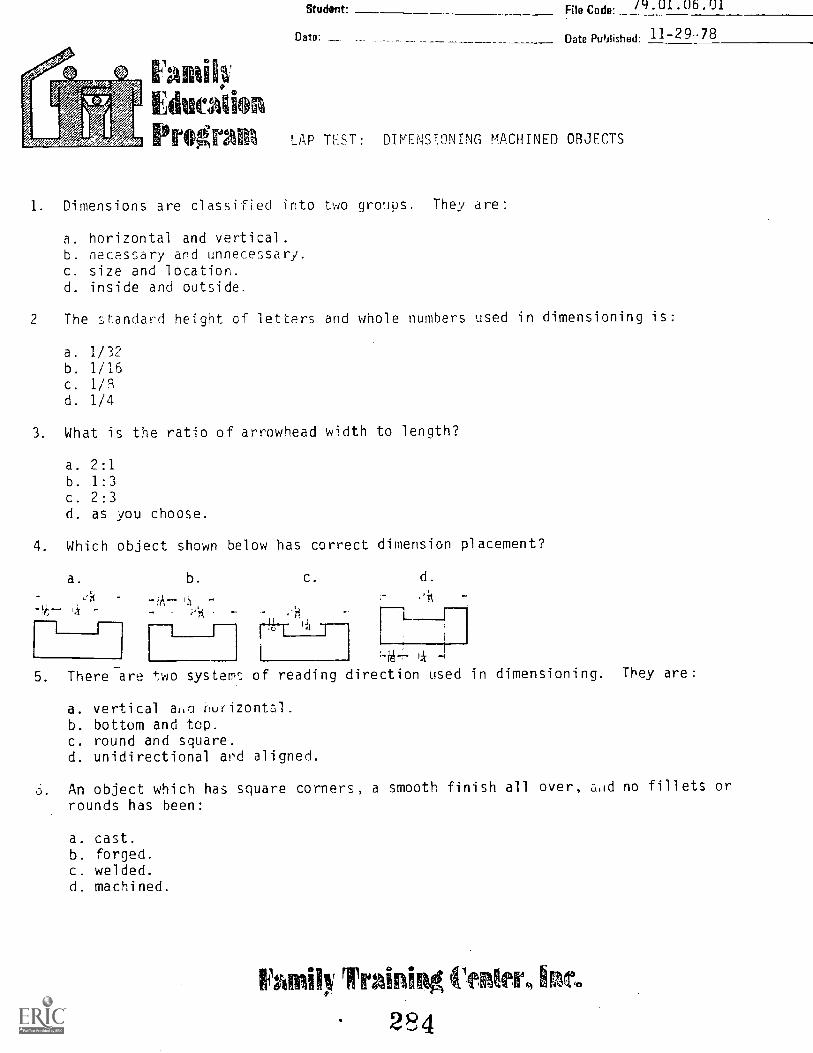
Student:
Date: _
[atilt'o.
Ethicadon
File Code: 79'01'06'01
____ Date Published: 11-29.78
PrOgrign LAP TEST: DIMENSTONING MACHINED OBJECTS
1. Dimensions are classified into two groups. They are:
a. horizontal and vertical.b. necessary and unnecessary.c. size and location.d. inside and outside.
2 The st.andard height of letters and whole numbers used in dimensioning is:
a. 1/32
b. 1/16c. 1/Rd. 1/4
3. What is the ratio of arrowhead width to length?
a. 2:1b. 1:3c. 2:3d. as you choose.
4. Which object shown below has correct dimension placement?
a. b. c. d.
4 1
_ 71'---
[7
1
, H5. There are two systemc, of reading direction used in dimensioning. They are:
a. vertical at,c1 nurizont,-,1.
b. bottom and top.c. round and square.d. unidirectional and aligned.
6. An object which has square corners, a smooth finish all over, acid no fillets orrounds has been:
a. cast.b. forged.c. welded.d. machined.
tigdnii," training (*ger, km*.
284

Page 2 79.01.06.01
7. If space is limited, the correct way to indicate dimensions is:
1c. aT d.
Allarecorrect.
8. Which of the following dimensions would be giver, as a radius?
a. f-:11et.
b. drill.c. hole.d. ream.
9. The first dimension line should be inch from the object and inch from
the next dimension line.
a. 1/4; 1/4
b. 3/8; 1/4
c. 3/8; 3/8
d. 1/2; 1/2
10. Which rule listed below has priority over the others?
a. dimension lines muet not cross.b. dimensions must be between views.c. dimensions must be on a profile view.
d. all are equally important.
2 53 5

7Q.o1.nr"ol
LAP TEST ANSWER KEY: DIMENSIONING MACHINED OBJECTS
1. C
2. C
3. B
4. A
5. 0
0
7.
8. A
9. B
10. A
296
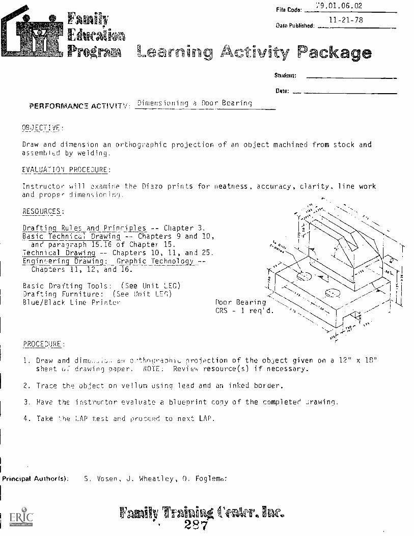
F dutiikon?OgrA51 Learning ActivRy P d i ck
File Codo9.01.06.02
Owe Published:11-21-78
PERFORMANCE ACTIVITY.: Dimensioning a Door Bearing
OBJECTIVE:
Studims:
Draw and dimension an orthographic projection of an object machined from stock andassembiLd by welding.
EVALUATION PROCEDURE:
Instructor' will examine the Diazo prints for neatness, accuracy, clarity, line workand proper dimensioning.
RESOURCES:
Draftina_Rules and Principles Chapter 3.Basic Technc; Drawing -- Chapters 9 and 10,ane paragraph 15.16 of Chapter 15.
Technical Drawing -- Chapters 10, 11, and 25.Enginr.,ering Drawing: Graphic Technolo_gy_r--
Chapters 11, 12, and 16.
Basic Drafting Tools: (See Unit LEG)Drafting Furniture: (See Unit LEG)Blue/Black Line Printer
PROCEDURE:
Ts.
Poor BearingCRS 1 regsd.
1.
2.
3.
4.
Draw and dime:.,;o:, a;1 o:thonrabili proiction of the object given on asheet Ci drawing paper. NOTE: Revie,N resouce(s) if necessary.
Trace the object on vellum using lead and an inked border.
Have the instructor evaluate a blueprint copy of the completed :hrawing.
Take LAP test and proceed to next LAP.
12" x 18"
Principal Author(s): S. Vosen, J. Wheatley, 0. Foglemo:
Familv Ccauar.287

hat4O
EthicAionmgrs LAP TEST: DIMENSIONING WF:.DED/MACHINED OBJECTS
Studant:
Date.
File Code: 79.01.06.02
Date Published: 11-29-78
1. Drawing scale is lisoally shown:
a. at the top left-hand corner.b. on the object.c. in the title block.d. in feet.
2. Center lines may be used as a(n):
a. extension line.b. dimension line.
leader.
d. arrow cad.
3. The following symbol is a specialize° weld symbol. What does it mean?
a. triangle weld.b. fillet weld-arrow side.c. 300/600 round weld.d. weld all over.
4. A note on a drawing is:
a. used to provide detailed information.
b. shown in all views.c. lettered in 1/4 letters.d. rarely used.
5. Every draftsperson uses weld symbols:
a. that he on.
b. which are jcl-e.nt f=P those welch other draftspersons use.
c. on every objectd. which conform to PWS Standards.
Amilw Trtining Centerc,
, 298

7q.n1.06.n2
LAP TEST ANSWER KEY: DPENSinNING WELDFD/MACHINED ORJFITS
C
2. A
3.
4. A
5.
289
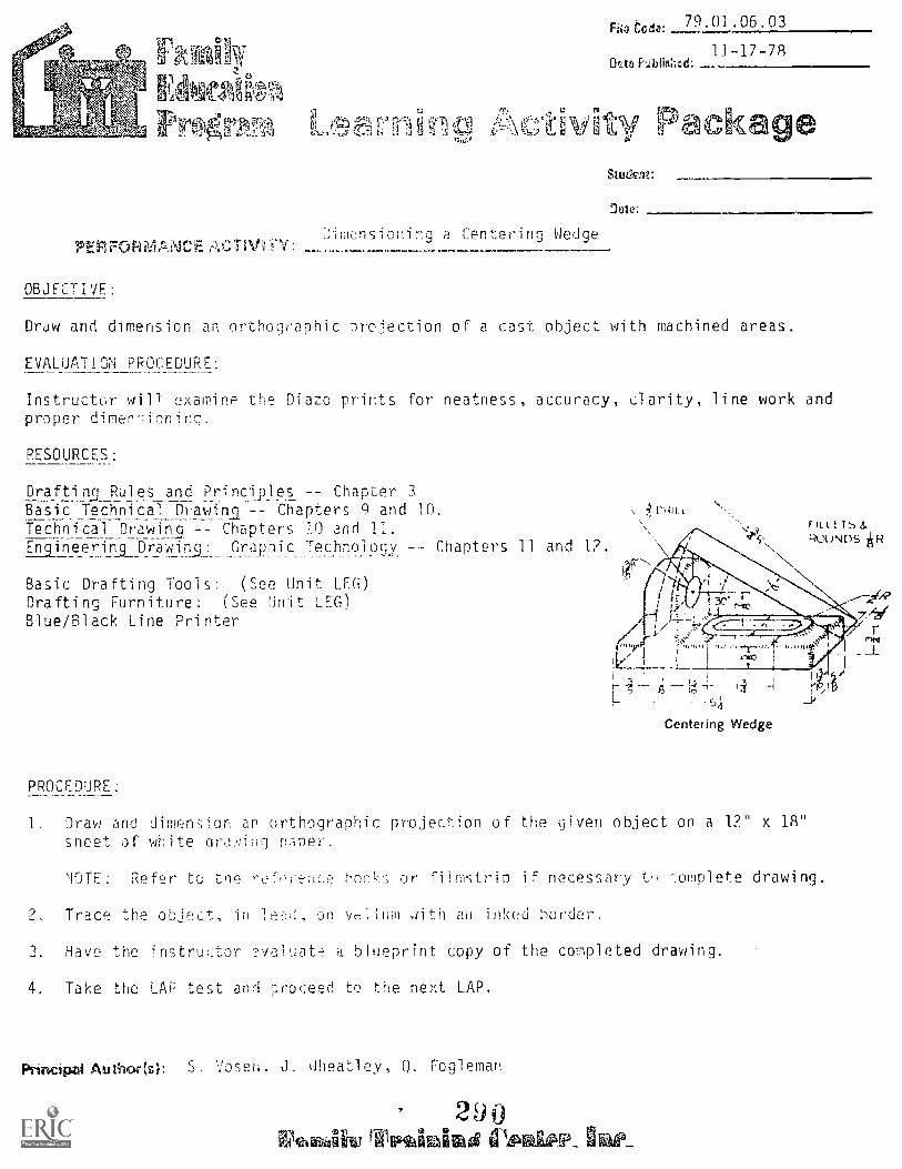
Culgla4g4W-PT
11 11
41114
10.44610-)A5,,,)511 r' V-C)
r car 79.01.06.03
11t blid 11-17-78
VAN' Pac<LeStuden/:
'Jute:
PER FOR MANC E. TDimensionirg a Centering Wedge
lc :
OBJECTIVE:
Draw and dimension an orthographic projection of a cast object with machined areas.
EVALUATION PROCEDURE:
Instructor will examine the Diazo prints for neatness, accuracy, clarity, line work andproper dimen'joning.
RESOURCES:
Drafti Rules and Principles Chapter 3Basic Technical.Dnawinl -- Chapters 9 and 10.Technical Drawin9 -- Chapters 10 and 11.Engineering Drawin.9: Graphic Technology Chapters 11 and 1?.
Basic Drafting Tools: (See Unit LEG)Drafting Furniture: (See Unit LEG)Blue/Black Line Printer
Centering Wedge
PROCEDURE:
1. Draw and dimension an orthographic projection of the given object on a 1?" x 18"sneet of white ordviihc] paper.
NOTE: Refer to the refeeeuee bne!r'; or filmstrip if necessary L .oniplete drawing.
2. Trace the object, in leeJ, on vellum with an inked border.
3. Have the restruetor evaluate a blueprint copy of the completed drawing.
4. Take the LAP test and r;roceed to the next LAP.
Principvi Au tho4r (z): S. Vosen, J. dheatley, Q. Fogleman
210rgifinarmi, tiI,Pnikale_ kV_

Studont _
Ofra: Date Published:
LAP TESH DIMENSIONING CAST OBJECTS
1. A cast object can he identified by
a. the sharp corners and smooth finish.b. the thinness of the sheet material.c. the fillets, rounds. and rough finish.d. the machine finish marks.
A line which runs from a note, to the object, ending in an arrowhead is a(n)
a. leader.b. extension line.c. dimension line.d. r to line.
3. The r7terial the object is cast from will be shown either in the title box or:
a. tho parts list.b. thE. horcer.
c. on the object.G. in a ncte.
4. The si..e of fillets and rounds is usually given:
a. on the object.b. in a note.c. in the title block.d. in thousandths of an inch.
5. Most dimens.-.ns Last ob:,Lc+ Pre either overall dimensions or are taken from:
a. rough edges.b. machined surfaces.c. the rounds and fillets.d. notes.
Fng w r91nri mtn° Ezo,
291
ggz nobJc,

LAP iFST ANY4ER FEY: DIMENSIONin CAST T1JECTS
1. C
2. A
3. D
4. B
5. B
292
7q.01 .n6.03

0,1 a Holder Cl in
OBJECTIVE:
70 01 06 04File Codo:
Data Putri;shud- 11-20-78
t!tLi.2.1
Student
Draw and dimerisio:1 an i)roje:tion of an object manufoctured from sheetbrass.
Instruc__Ur 4111 exanin:, Cqeand
SOJiiES
Di a .ints for neatness, accurany, clarity, line work
Drafting Rul es and Princi pi es 3
Basic Technical Drawin.g Chapters c; and 10
Technical Drawinf -- Chanters 10 and 11Engineering Drawing and jra_phif.: Technology Chapters 1] and 1?
Basic Drafting Tools: (See Unit LEGYDrafting Furniture: (See Unit LEG)Blue/Black Line Printer
PP.00ESDIJRES:
e\
Holdnt Clip
1. Dra.,.: and dimension an orftrgraphic projection of the given ject on a 12" x 18"
sheet of drawing oaper_ NO."7: Refer to the reference hooks and/or filmstrip ifnecessary to complete drawing.
2. Trace the object, in lead, on a sheet of vellum With an inked border.-, Have the instructrw ,3.valliate_ a blueprint copy of the completed drawing.4. Take the LiiP test and proceed to the Performance Test.
Principal Aavvhori S. Vos2n. J. Wheatley, C. Wetterling
giharcia.Aika
Mtud4mt: File Code:79.01.06.04
Date Published 11-29-78
LAP TEST: DIMENSIONING FORMED SHEET STOCK
1. When dimensioning objects formed from sheet stock, the thickness dimension is usuallygiven:
a. in the front view.b. in the right side view.c. as a note.d. in the title block.
2. The center line of a sheet metal bend is called the:
a. bend allowance.b. neutral axis.c. inside mold line (IML)d. outside mold line (OML)
3. Dimensions should be placed in the view that shows the _ _ _ of the object.
a. contour.b. edge.c. top.d. front.
4. What does the abbreviation NTS stand for?
a. National Technical Society.b. Not To Scale.c. Not Too Symetric31.d. No True Shape.
5. Center lines 1,:i ano
a. object lines.b. dimension lines.c. extension lines.d. leaders
EA vinglw TrwirfAiP\o's 0m7Atle7
2,94

70.01.06.04
LAP TEST ANSWER KEY: DIMENSIONING FORMED SHEET STOCK
C
2. B
3. A
4.
5. C
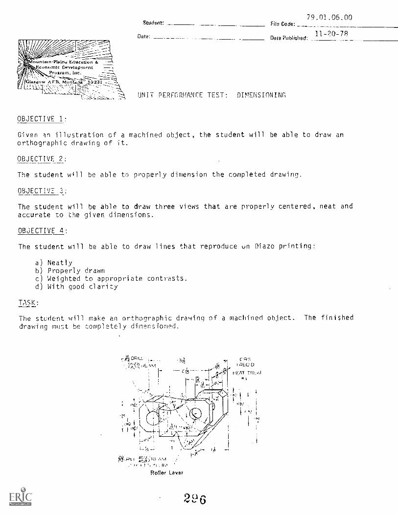
Stud:int:
Date:..--c-l--7-7,,i_I---,:-..-%"\v --,.0-15-----_--.--- -7-_-:
_-_,------------ ------------------<e- -- -,..f..-------;-.....-
,untain-Plaln.a Education dt,conomIc Development --.1
I \Program, Inc...,_
----.**-cr-z.-....1--- -.7------7./Glasgow AFF3, Nforilan.ti _57/231 ---....-z.,LIA.11.1.1. `'.><`.'--'' -,. 1
[:',..;2- '.12-'-L: :..- UNIT PERFORMANCE TEST: DIMENSIONING
File Code:79.01.06.00
11-20-7RDate Published:
OBJECTIVE 1:
Given an illustration cf a machined object, the student will be able to draw anorthographic drawing of it.
OBJECTIVE 2:
The student will be able to properly dimension the completed drawing.
OBJECTIVE
The student will be able to draw three views that are properly centered, neat andaccurate to the given dimensions.
OBJECTIVE 4:
The student will be able to draw lines that reproduce un Diazo printing:
a) Neatlyb) Properly drawnc) Weighted to appropriate contrasts.d) With good clarity
TASK:
The student will make an orthographic drawing of a machined object. The finisheddrawing must be completely dimensioned.
-II `I I 1,[ 'I.' \ :
. Ii
: I ....1...-....
1 1 c? .--i i 4' \.__L 41.1' ...1Q''-
! ,,-- lo."5\_--- i'
4 1
V.:..e'1..
i_,I,L , 4p,k; Ill f,\,1,' +if )( l ' In i 11.0-
CR!=,.71 RE.Q D
rieed HEAT TREAd
;47,L.
ru.
Roller Lever
2 9 6
Page 2 74.01.06.00
ASSIGNMENT:
Draw and dimension the "Roller Lever" found on previous page. [Ise 12" x 12"
drawing paper and reproduce a Diazo print.
CONDITIONS:
The drawing is to Le completed in a typical drafting room setting, using the com-plete facilities.
The student will not oe able to use the instrucLor(s) or other students as a re-source.
REsnuocs-
As described in the Unit LEG.
2,97
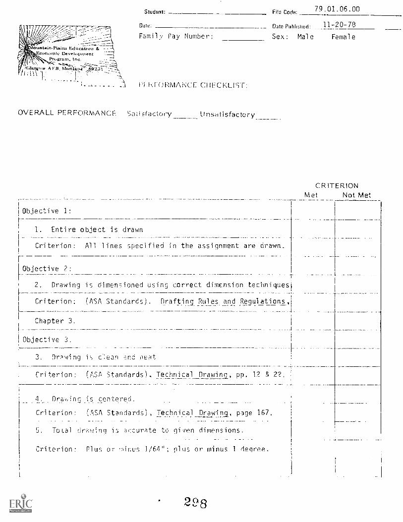
ounlain-Plaina Educaliou.r.onomic Development
Program. 'Inc.
i(ilgtgow AFB, 69231-
Student:
Ds::
Family Pay Number:
Filo Code: 79.01.06.00
i'I.M.ORMANCE CHECKLIST:
OVERALL PERFORMANCE Saiisfactory
Objective 1:J.
Unseitisfactory
Date Published: 11-20 78
Sex : Mal e Female
CRITERIONMet Not Met
1. Entire object is drawn
Criterion: All lines specified in the assignment are drawn.
Objective 2:
2. Drawing is dimensioned using correct dimension techniques
Criterion: (ASA Standards). Drafting_Rules and Regulations,_ _ _
Chapter 3.
Objective "'J.
3. Drwing is c.ean ne:it
Criterion: (ASA Standards), Technical Drawina, pp. 12 & 2?._ .
4. Dra.v,:ing.s centered.
Criterion: (ASA Standards), Technical Drawina, page 167.
5. Total dri-ming is acr..:ur;ite to given dimensions.
Criterion: Plus or minus 1/64"; plus or minus 1 degree.
2,98

Page 2
(Checklist continued)
79.01.06.00
CRITERIONMet Not Met
Objective 4:
6. Hidden lines are neat and properly di..1wn.
Criterion: (ASA Standards), Technical Drawing, page 145.
7. Visible li:les are neat _Ind properly drawn.
Criterion: (ASA Standards), Technical Drawing, page 20.
8. Center lines are neat and properly drawn.
Criterion: (ASA Standards), Technical Drawing, page 20.
)---_
i
9. Hidden lines are 3f appropriate contrast in relation to
the other lines and repro-uce clearly on Diazo print.
Criterion: (ASA Standards), Technical Drawing, page 20.
10. Visible lines are of appropriate contrast in relation to
the other lines and reproduce clearly on Diazo print.
Criterion: (ASA Standards), Technical Drawing, page 20.
11. Center lines are of appropriate contrast in relation to
the other lines and reproduce clearly on Diazo print.
Criterion: (1,..*' c',.=-,.uards), Technical Drawing, page 20.
12. The drawing is completed in the specified length of time.
Criterion: Not to exceed 9 hours.
The student must meet criterion on 10 line items to obtain an
overall score of satisfactory.I

Ountaln-Plalrts Education &onomic Development
Program, Inc_
Glasgow AFI3. Monstsnii 159231
Student:
Date
1. Line 1 at right is:
File Code: 79.01.06.00. B2-2(.01.04)
Date Published: 6/20/74
UNIT/LAP POST TEST: DIMENSIONING
a. an extension line.b. a dimension line.c. a continuation line.d. an object line.
2. The system of writing dimensionsshown at the right is the:
a. only system used.b. the aligned system.c. bottom system.d. unidirectional system.
3. Line 2 at right is:
a. a dimension line.b. an extension.
a continuation line.an object line.
4. The dimensions necessary to completely describe the size of thesize of' the object below are:
a . BcDFC-2; LT.:m..1 A
b. a.c dimec.)ns are ',::cr-?ssary.ABDEG and F
d. ASCEF and J.
-c.ro 1471
309
Ma.

Page 2
5. The best example of dimensioning the object is:
tORiLL
A
b.
d. all are equally as good.
01211L
C.
79.01.06.00. B2-2(.01-.04)
6, Drawings should be made to scale, and the scale should be indicated;
a. on the object.b. in the title block.c. outside the border line.d. only when smaller than full scale.
7. A fine, dark, solid line that extends from a point on the drawingto which a dimension refers is
an extension line.b. a dimension line.c. a visible line.d. a center line.
8. A fine, dark line composed of alternate long and short dashes usedto represent axis of symmetrical parts is:
a. a dimension line.b. a center line.
a hidden line.d. a leader.
301

Page 3 79.01.06.00. 82-2(.01-.04)
9. Arrowheads should be drawn with the length and width in a ratio of:
a. 5:1b. 2:1
c. 4:1
d, 3:1
10. The symbol that indicates a surface is to be machined is:
a . a boss mark.b. a casting mark,c. a forging mark.d. a finish mark.
302

UNIT/LAP POST TEST ANSWER KEY: DIMENSIONING
1. A2.3.
D5. A6. B7.8 . 29. D
10. D
303
79.01 .06.00. B2-2(.01-.04)

1\,11
ftfountzsinileins S-"Aucation Ifz
D^VV elo pm entinc.
GLasgu w A F' B. Muntaria L92:ri- \1
RATIONALE:
HN f T: SECTION VIEWS
File Code: 79.01.07.00.A2-1
!lain Published
Revised: 7/14/78
The common method of representing an object is by drawing its views. Whenevernecessary hidden part, or (.-.des are shown by using hidden Unes. However, some-times the hidden edges are more clearly shown by drawing a section (or cross section)view. The section view illustrates the object cut apart.
PREREQUISITES:
Unit:
OBJECTIVE:
The students become tjamiliar with the terms used in sectioning. They will
identify and draw the rollowing section views; full-sections, hal f- sections, broken -out sections. revolved sections, r,-.-moved sections, and off-set sections.
PESOUPCES:
Printed Materials
BasicTech7lice.1 Drawn.
c,nercer Drydon , Macmillan Company , New York.
Eh gi neer; ns Drawing and i_raphicTe_c.hriology. French and V: Derck , Eleventh Edition,
McGraw -H Pouk Comny , Uevi York
Mer:han ical C.racirlg. Frinc,;, and Svenson , Webster Ni vision , McGraw -Hill Book Company,
New vuT7,chri i cu GiesetA,, '.,pencer and Hill, Macmillan
Company,
o tin Visuals
Section ...)ro.::nj Poubleday Multimedia
ri pment
A , 1 i ,,t2d
Author(* C. , L. Leland, S. 'los en , 1,411 eat I ey
3n4

Page 2 79.01.07.00.A2-1
Drafting Furniture: As listed in Course LEG
Player, audio cassetteProjector, filmstrip
GENERAL INSTRUCTIONS:
This unit consists of eight Learning Activi.cy Packages (LAPs). Each LAP will pro-vide specific information For completion of a learning activity.
The general procedure for this unit is as follows:
1) Read the first assigned Learning Activity Package (LAP).2) Begin and complete the first assigned LAP.3) Keep the drawing mounted on the board until it has been checked and approved by
the instructor:4) Take LAP test as instructed in each LAP.5) Proceed to and complete the next assigned LAP in the unit.5) Complete all required LAPs for the unit by following Steps 3, 4, and 5.7) Take the unit post and performance tests as described in the unit LEG "Evaluation
Procedures".8) Proceed to the next assigned unit.
PERFORMANCE ACTIVITIES:
.01 Section Views Terms and Usage
.02 Half and Offset Sectioning
.03 Removed, Revolved, and Broken-Out Sectioning
.04 Section Views of a Tool Frame
.05 Section Views of a Lift Bracket
.05 Section Views of a Discharge Lock Housing
.07 Section View of a Stabilizer Bracket
.08 Section Views of a Slotted Disc
EVALUATION PRDLIbUr,.E:
1. The student completes LAPs and takes the LAP tests as required.
2. The student takes a multiple-choice post test and turns it in r correction.
3. The student takes a unit performance test. Successful unit completion is meetingthe listed criteria for the performance test.
FOLLOW-THROUGH:
Whenever it wil! bncow,2 i.ece7,sary to show the interior ports of an object, sectionviews will be used and monitored throughout the course.
Begin the first assigned Learning Activity Package (LAP).
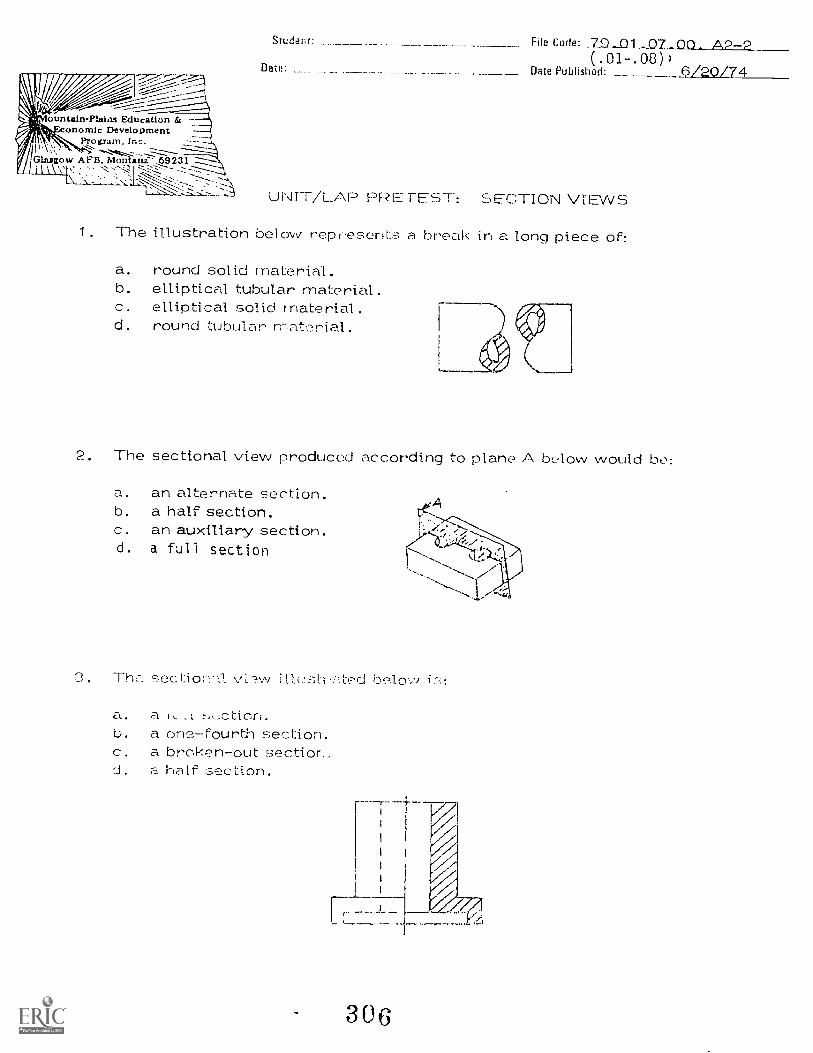
ountairiPlaills Education E.,.onomlc Development
Program, nc.
Glaittow RFD. Mon ani- 69231
Student:
Date:
File Code: 7.9 .._01 A2-2(.01-.08)
Date Published: 6/20/74
UNIT/LAP PRE TEST: SECTION VIEWS
1. The illustration below represents a break in a long piece on
a. round solid material.b. elliptical tubular material.c. elliptical solid material.d. round tubular material.
2. The sectional view produced according to plane A below would be
a. an alternate section.b. a half section.c. an auxiliary section.d. a full section
3 . rho:. section - iLft!sti...,:ited belay/
a. a ik...LL
b. a one-fourth section.c. a broken-out section..d. a ha lf ction.
306
Page 2 '79.01.07.00. A2-2(.01-.08)
4. A half section is obtained \:-../hen:
a. three-quarter or the piece is cut out and removed.b. one-half of the piece is cu,i. out and removed.c. one-quarter of the dace is cut out and removed.d. one -third of the piece is cut out and 1-emoved.
5. A convenient means of showing the shap of a rib, arm, or longfeatur.-: is:
a. a half section.b. a revolved section.c. a full section.d. a broken section.
6. The type of view that shows interior features of an object is:
a. a sectional view.b. a top vievv.c. an auxiliary view.d. an end view.
7. A view obtained by passing a cutting plane completely throughan object is:
a. a full section.b. a half section.c. a revolv'er' section.d. := /ed section.
8. The direction of sight for a sectional view is indicated by:
a. the arrows at the ends of the cutting plane..b. the position of the front view.c. the length of the projector:-;.d. he direction of the section lines.
307

Page 3 79.01.07.00. A2-2(.01-.08)
9. On detail drawings, the ASA rec:.;ns,mend,3; that all materials berepresented by the ,J,.,,ction lining for:
a. aluminum.b. cast-iron.c. wood.d. plastic.
10. The pencil lead to use or drawing section lines is:
a. 13 or 22.b. 41-1 or 6H.C. Hor2H.a. 4B or eiB.
308

UNIT/LAP PRETEST AN',./EP : SECTE01\1 VIEWS
1. D2. A
3. !ID
4.5. B6. A7. A3. A9. B
10. 3
309
79.01.07.00. A2-2(.01-.08)

=MIL4.2..741Airit:.&',"=.0.
Educutiorl &1.:4,41,111, 1).velpiriont
l'r.,;:rani.
Ousgow MotItiltiza 5'1231 tI u 7Jc,,e9
.t43 7' 17i;'' 'N ti
Sect 1 J 011 Us agePFRFORVANCE ACTI"RTY. .
OBJECTIVE:
79.01.07.01. A2-0R e CodP
12/17/75hate Publish"d
Revised: 7/14/78
StudGM:
Data:
r2)
Understand the reason for .;ecf.:1oninri ond draw the giver ohjects in full section.
EVALUATION PROCEDURE:
Instructor vi ill exawine drE41 nu a pi nst e prepared key for accuracy, dimensioning,
1 ne construction, neatness and 1 etteri ng. No more than three errors will be allowed.
RESOURCES:
Technical Drawingin -- 7-i page 203 -- toBasic Technical Drawi na, Chapter II'Mechanical Drawl na, Chapter l0.
Secti ons , Draft i ng Seri es .
Basic Drafti ng Tools: /See tin i t LEG)
Drafting Furni ( SeE: it LEG)
Filmstrip projectorAudio cassette player
PROCEDURE:
7-8 page 211.
I. Rea.: the resourLrE(s.
2. View the fi 1 mstri n on .
3. On the or thi 1 Ptter the de fi nitions
4. Draw the section vi.Pws (-1V(J.11 on the three qnment
5. Have your draw i -7:va 1 c-it ed.6. Take the ' P Le fl3.
Principal Author(s): Q. Fog I eip.F.In S . ,

1. 2.
5.
311
6.
t
i \/ ---1 I -1,_
,,\
i---.
_L_

I1,177"- -1
,-------1-_-7---.....,
),---
,-.
\\
co
7
1-A).
-
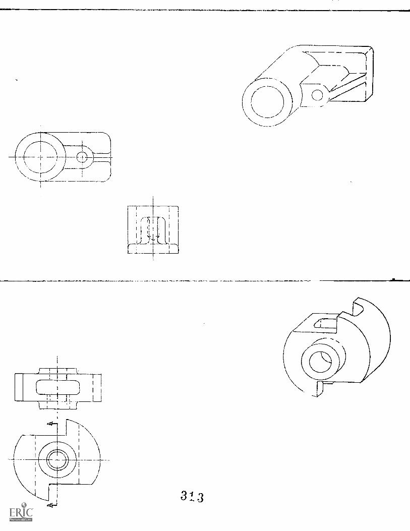
H Ls
1I h
313

!Ihlt,untain-I'lutt). Etiticit' lor 41
V;EC,1101M.'0,,,I.d1"enti: ,tiFil'il'r.t:r...1. , I Tit .
( .I..iygi,V. .N111, NI, .r, Lint, 5!3 2:s 1 0%,..,
''',_......L. .1.-.
PERFoRmANck: AcT;v1T,2,.. cHi Oft- '5, t. (::q2 C
OBJECTIVE:
79.01.07,02.A2-0File Coll
OmePeOishd.
Revised:
12/17/75
3-19-79
Pat
Draw half algid off-set cctm veis of vF:irioi:s objects.
40. e
EVALUATION PROCEDURE:
Instructor wili examine drawings against a prepared key for accuracy, dimensioning,line construction, neatness and lettering. No more than three errors will be allowed.
RESOURCES:
Basic Technical Drawing, Chapter 11. Paragraphs 11.4 and 11.8Mechanical Drawina, Chapter 10.Technical Drawing, Chanter 7.
Basic Drafting T.,0: Ht LFG)Drafting Furniture: Se Hr .fl)
PROCEDURE:
1. Dr-an the Hevs of c;1 rncJirni (Jbject hewn on the assignmentsheets ' J1b(;ve re;o,,rce'3(;).
NOTE: Use 1sP rsas Le cimolete the drawings if necessary.
2. Have 1±. the r,lr,Iwings.
3. Take LAP test LAP H.
Principal Amzholls): Q. Fogle, S. V-)seH, J. Inf!(:Lle'Y
314

Draw the half sections indicated on th r. objects below.
I I
PULLEY
(
1
--,\ \,,,
-.. \ \.
\Draw the hal I' /
Jsection ON Ole / /_.-
----object. / /
.// /,_--
SUPPup,i Box
3 1
79.61.07.02 pg. 2
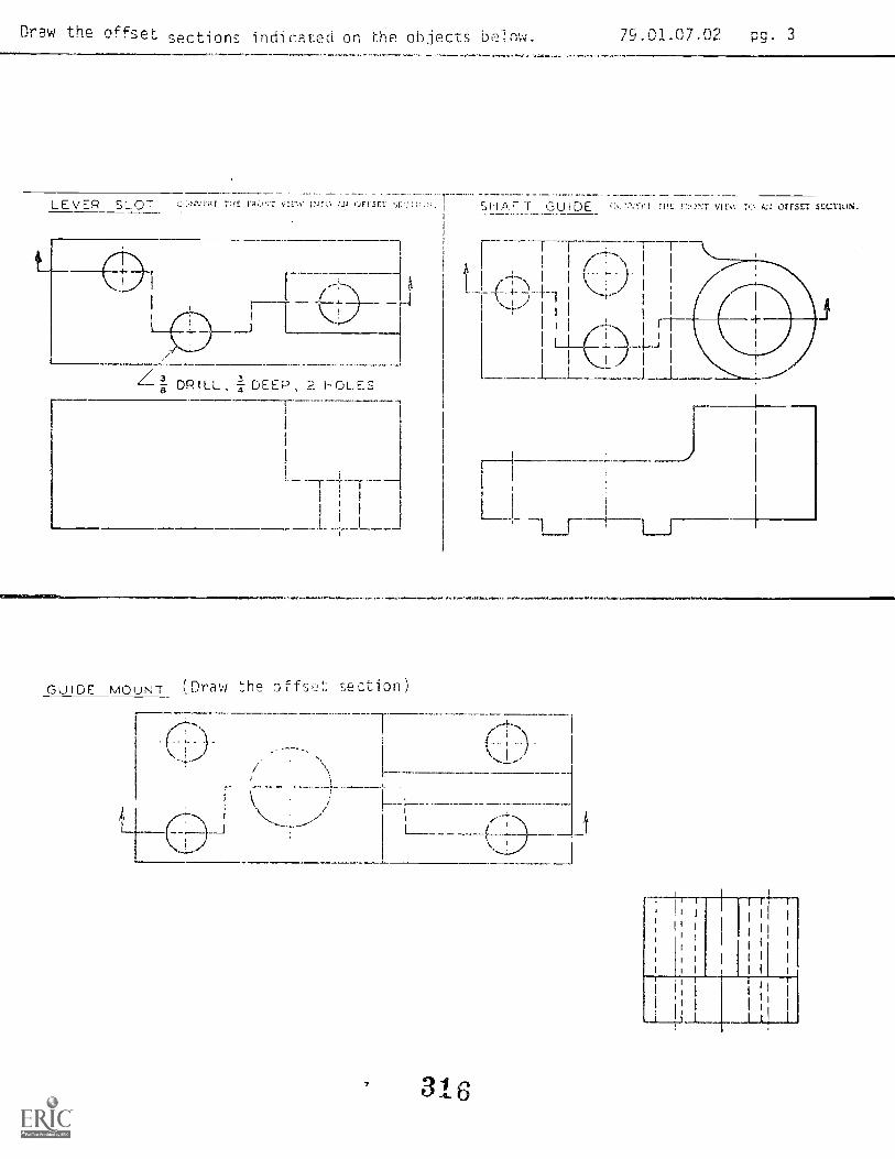
Drew the offset sections indicated on he objects below. 79.01.07.02 pg. 3
LEVER SLOT 711E r;,t,-.)NT OFF SCT SH A F -r GU I DE C:k.'r:\Ti I r;!!: 2!:1- VIEW rc UFFStT sEcTioni.
DRILL, -I- DEEP HOLES
GUIDE MOUNT ( Draw the 0 ffsiJt: section)
1 I rt. 1
I I
I
I I IHI(.±
III./1__L_
Li
\. I
316
dfl

MmInt.lin- Ian. t1.1:ationrc,mmt,"Prum, ,?
N:14,111.,01,. 59231
MiR
D6:erublishew
Pevist,d:
79.01.07.03.A24
1?/17/75
3-19-79
trO ",g,
r 1 .
FT-% P-1ift).
Stud,t
IC
Boii-Out ::)ection ViewsPERFORMANCE. ACT;ViTY: r
OBJECT'
Dro1i the indicated cc 1 1!' nord lrrts
EVALUATION PROCEDURE :
instructor will examine drawings against a prepared key or accuracy, dimensioning,line construction, neatness and lettering. No more than three errors will be allowed.
RESOURCES:
Basic Technical Drawing, Chapter 11, page 197.Mechanical Drawing, Chapter 10.Eriaineering Drawing and Graphic Technology, Chanter B.
Basic Drafting Tools: San ;;Ht, LEG)
Drafting Furniture: (See Unit LEG)
PROCEDURE:
1. Draw the inclicatPd setio!i views oF tne given ohjects on the assignment sheet.
NOTE: hooks as references to complete the drawings.
Have the in.,tructor ckawirris:.
3. Take the LAF tos t over LRP,.. .01, .02, nd .03.
Principal Author(s): Q , Fog' , S . V() Pr); 3 J. icy
317
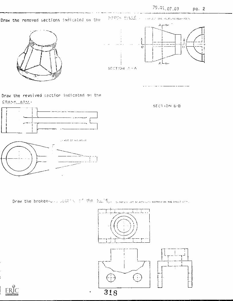
Draw the removed sections indicated on the
Draw the revolved section indicated on the
CRANK ARM
rAf. ATI,
Draw the broken-u.,.. z
TIll
r,"07.03 pa. 2
o)i. P,,
A
L
SECT ION A A
i.-.1- rrJ IN
SECT ION ri3-B
c. t..I'; SECIIG:7 IN TIIE.
318
_1 I

Mountaiti-Plam,Edu1 %4
(;114141,... AI' IS.;
79.01.07.04.A2-0
Dio.e,=iliAlsila: 12/17/75
Date Revised: 7-12-78
,PERFORMANCE AC1-1;,TI:!': 1T L
OBJECTIVE:
Draw the various section T, tool
EVALUATION PROCEDURE
Instructor
SioCf;o,:
(I e
Ht:y for i-1;:ciir,icy, dimensioning,
line cow..;truction, IF!t.HcHj. tHH tcrors will he allowed.
RESOURCES:
Technical Drawing, Chapter 7Basic Technical Drawing, Chapter 11Mechanical Drawing, Chapter 10EngineeringDrawing and Graphic Technology, (La;,.)erBasic Drafting Tools: Sae Onit LEG)
Drafting Furniture: LEG)
PROCEDURE:
1. Draw the indicated section -views of a tool froolle shown on the assignment sheet.
NOTE: '.1(m may usa yeJw.ce .-)ooks at; ferencos to coraplate the drawings.
2. Have the ins,
Principal Anther(s): Q. Foql Whea
319

F -
r
79.01.07.04A1
rcr,--1,..."-J1,,,,ILLVILZ...04/_C:1/7JITZ,
111
!Mountain -1'ta ms Ecluvallmi tl., (1.:emiwilic 1)-v-1:pinent
Pr,,,,r,ii. 1,1....
td,..gwAl.Ai.N1.nLma
Zraz.4
PERFORMANCE ACT)VITV
OBJECTIVE:
79.01.07.05.A2-0Code:
1?/17/75UmaPublished:
Revised: 7-12-78
,
!
uczivn d Lift E;racket_ -V _ - - - . - - - ---
Draw the various 5ectio:i vi a lift bracket,
EVALUATION PROCEDURE:
StuthW.:
Dale.
ge
Ins t r,J,c acJai Hst a prp,a kr..,y for accury di mens i oni ng,
line consli ruct on, neatnes 1 et teri h g . no iore than three errors *ill be al lowed.
RESOURCES:.
Basic Technical Drawina, Chapter I .
Mechanical Drawing, Chapter 10Technical Drawing, Chapter 7Basic Drafting Tools ( See Unit LEG)
Drafting Furniture: (See Unit LEG)Engineering Draw i ng and Graph; c TeOnol ogy, Chapter 8
PROCEDURE:
1. Draw the indicated section vi ews of a lift bracket shown on the ass i gnment sheet.
NOTE: '11,-; may u ,e l'ef:ource books as references to complete the drawl ngs.
2. Have the ipsL. e (.; t s
Principal Author(s): C. We tterl in g, j. Clheati ev

C./
V
CI
rn
43"c"'so
-zoLo
64

,..i
rai---.....
iPr,i;r.iir,. In
AI ;1,,,Itviw
,zra:21-215:a 1 5 \.5.5.T.tam.rwrzt-44,_
1^4,writairi-P1,,Ilis Lacu 1,.11
;k,
79.01.07.06.A2-0
12/17/75Dat2Pubks!.eth
Revised: 7/12/18
r; ;,o
^.1 :11Y
D118:
StcLiu 'flews a hHc.rge Lock H:JtisingPERFORMANCE ACTIVITY:
OBJECTIVE:
Draw the various sctin view'.; or dischrge loci: 'r)using.
EVALUATION PROCEDURE:
The i 1 key acc ericy. dimensioning.
no cor;sAruction, n adi pttPriril. more thw th rn error', wi it he allowed.
RESOURCES:
Technical Drawing, Chapter 7.Basic Technical Drawing, Chapter 11.Mechanical Drawina_, Chapter 30Engineering Drawing and Graphic Technology, Chapter 8.Basic Drafting Tools: (See Unit LEGYDrafting Furniture: (See Unit LEG)
PROCEDURE:
1. Draw the indicated sect.c)n views of a discharge lock housing shown on the assignmentsheet.
NOTE: Yo:, ma : use , resour.':e hooks as references to comp ate the drawi ngs
2. Ha"e tru,.. to c 31U3 LC
Principal Anthor(s): Q. 1. Li yy
3
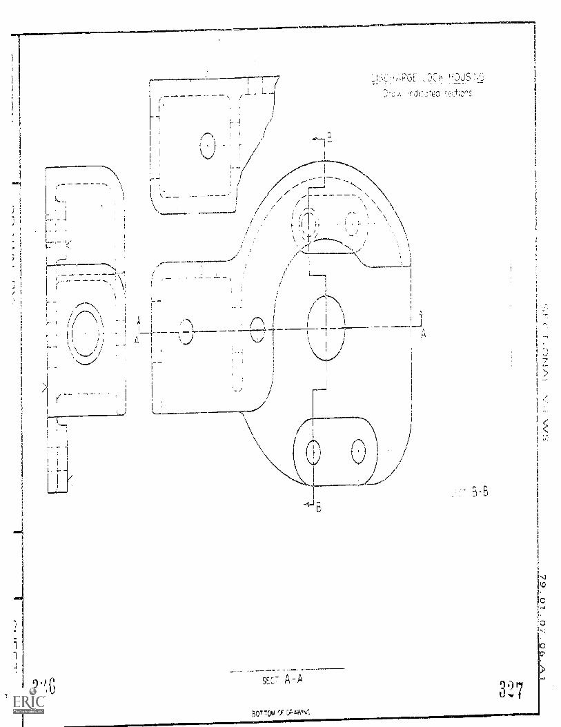
r
_
1
h
/--___---- -_-" ,/' // / --------,.\\
i
1
\' t'i 1 ,
,,.
;
,
i, N._ 1:
,
ii
,
c 1
! i i I \i
/
1
',...) J.i 1 \ " 1 A
L.; ..:....,/
SECT A-A
BOT-rOvg
3-B
Imsl.....
J
C

11 7S
,,,,,,,,,,,,,,,,,,,,,,, Fdncut ir,r;
w r, G U. 59231
Y'{"ZraZr
PERFORMANCE ACT IV IAN
1 !A
5
P d-70).01 .07. -7.A2-0
12/17/75UmePutled
e 7 1 q,
:ituegoOl
on View f a Stn bilizer lirac!:et
Draw a if1 iew oF a ti, i h
EVALUA 7 F-";::3LEF)LikE :
C.1,7 rem tia%.4,.NS)
instructor will emine drawiuj, againsi, prepared key for ac:ura,:y, dimensioning,line construction, neatness and leteing. No more than three errors will he allowed.
RESOURCES:
Technical Drawing, Chapter 7Basic Technical Drawing, Chapter 11Mechanical Drawing, Chapter 10Engineering Drawing_ and Graphic Technology, Chapter 8Basic Drafting Tools: -(See Unit LEG)
Drafting Furniture: (See Unit. LEG)
PROCEDURE:
1. Draw the indicated on views of a stabilizer brac!Et shorn on the assign-
mpnt
NOTF: You as as references to complete the drawings.
2. Have the drawi 7gs evaluated by the instructor.
Principal Author(s): Q. Fogleriian, J. Wheatley
3%j

r
Ti
BR.A0E:
[1.1row :eo:or
fl

Student.
Dam
Eductitten11014001alt LAP TES1: SECTION VIEWS
Filo Code:79.01.07LAPS (01-03)
_ Date Publistmd: 7-20-78
1. The edge view of the cutting plane is represented by which line.
a
b.
c.
d.
2. The direction of sight for a sectional view is indicated by:
a. the arrows at the ends of the cutting plane.b. the position of the front view.c. the length of the projectors.d. the direction of the section line.
3. In a section view, all visible edges and contours behind the cutting plane:
a. are not shown_b. are high-lighted.c. should be shown.d. should be removed.
4. A section view in which the cutting plane has passed through the entire object:
a. is never used.b. is an edge view.c. is a half view.d. is a full section.
5. When a section of the object is drawn adjacent to the view, it is called a(n):
a. removed s2,,tion.
b. rev.-dved
c. align `ion.
d. "otated section.
6. The sectional view producer; according to plane D in Figure 67 would be:
a. a full section.b. a partial section.c. a half section.d. a broken-out section.
141er
61019 (11 1E'r?C*. .
3 9

Page 2 79.01.07 LAPS (.01-.03)
7. The best sectional view of the object below is:
b. c. d.
8. The best illustration of section lining below is:
a.
9. The sectional view produced according to plane B in Figure 60 would be:
a. an alternate section,b. a broken-out section.c. an offset section.d. a double section.
10. The illustration in Figure 59 represents a break in a long piece of:
a. round solid material.b. round tubular material.c. ti.Hlar material.d. - sol-H1 matriu.
Figur(' 59

1. B
2. A
3. C
4. D
5. A
6. D
7. D
8. C
9. C
10. B
LAP TEST ANSWER KEY: SECTION VIEWS
3 st 3
79.01.07 (LAPS .01-.03)
1)..vt.1,,pinentPr"grAm.bw.
;Iumg,,w Al Is, Mnnlun., 542:11
1....4.0A1
M fing
79.01.07.08.A2-0File Code.
Date Publistied12/17/75
Revised: 7/13/78
tc. v.,vq -
Studcnt:
Date:
PERFORMANCE ACTIVITY: Section Views of a Slotted Disc
OBJECTIVE:
Draw the various section views of a slotted disc.
EVALUATION PROCEDURE:
Package
The instructor will examine drawings against a prepared key for accuracy, dimensioning,
line construction, neatness and lettering. No more than three errors will be allowed.
RESOURCES:
Technical Drawing, Chapter 7Basic Technical Drawing, Chapter 11.Mechanical Drawing, Chapter 10.Engineering Drawing and Graphic_Technolp_gy, Chapter 8.Basic Drafting Tools: fSee Unit LEG)Drafting Furniture: (See Unit LEG)
PROCEDURE:
1. Draw the indcated ,,:ectin views of a slotted disc shown on the assignment sheet.
NOTE: q();; v . the -rmrr:e books as references to complete the drawings.
2. Have the instructor evaluate the drawings.
Principal Author(s): Q. C. Wetterling, J. Wheatley
3 1) 4

...---,,/ \ \/ A1I N
i
/ /
\\
\\
//
//'
\\
\ \1
/ , \
/ // / .,.... \
/ r\\
1---1 I-I- f!
',I 1
,
HAL SL:' ON
lt)
SLOTTED DISC o"I co
Draw ;nd:ca!ed sections
C JL SECT O;
0
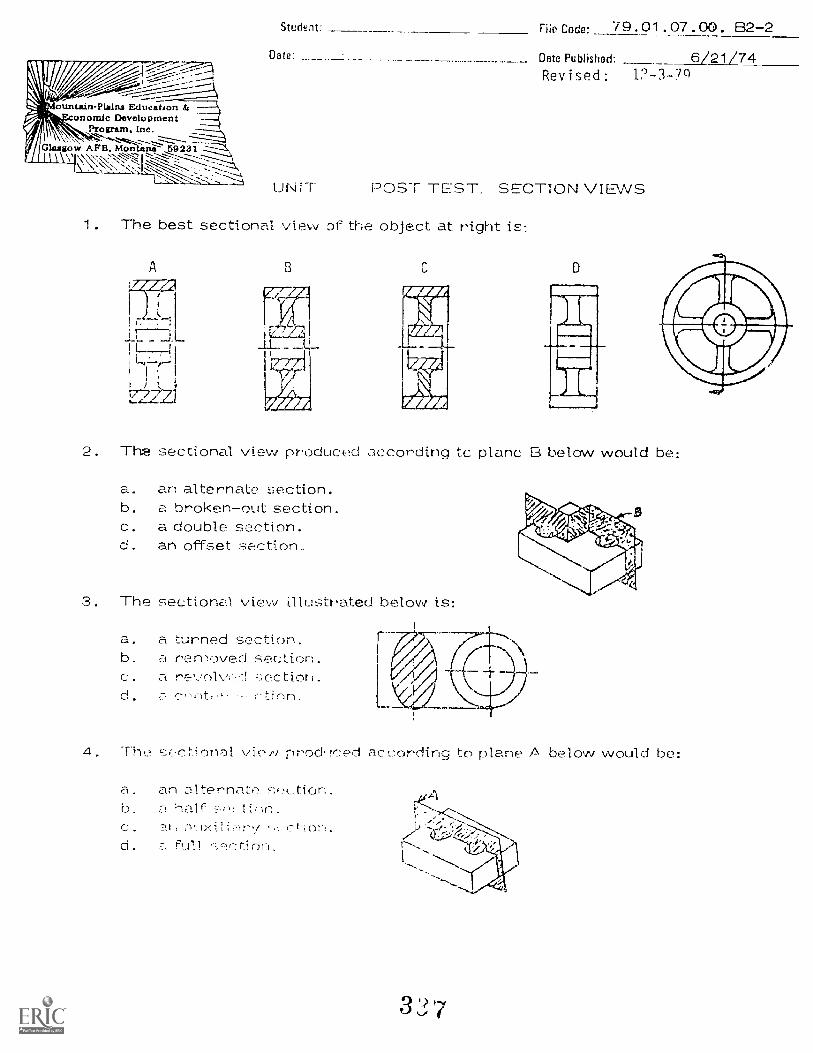
ounutin-Plains Education &
ILanomie Development
Program. Inc.
//Glasgow AFB, Mon nil .._69231\\
Stu1,2nt: Flip Code: 79.01. 07.00. B2-2Data: Data Publishoci: 6/21/74
Revised: 12-3-7q
UNIT POST TEST. SECTION VIEWS
1. The best sectional view of the object at right is:
C D
2. Tha sectional view produced according tc plane B below would be:
a. an alternate section.b. a broken-out section.c. a double section.d. an offset section..
3. The sectional. view illustrated below is:
a. a turned section.b. a removed section.a. a ,.;ectior .
d. ti on
4. The '7:;,-..ctionD1 vieiv prod teed according to plane ,A below would be:
a. an altr..7,rnatib. a hair 1)11.C. l'At: (7-
d. a Fu1.1 'r tjQfl
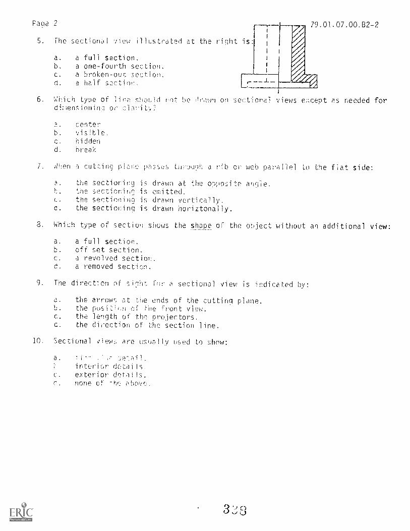
Page 2 r-T- 9.01.07.00.32-2
5. the sectional view illustrated at the right is:
a. a full section.b. a one-fourth section.c. a broken-out section.d. a half s2ction.
6 Which type of line shou!d rot he (Yawn on sectional views e;:cept as needed fordiens;oninq or cW.it.,,?
centerb.
c. hiddend. break
7. Ahen a cutting plae passes tliouhh a rib or web parallel to the fiat side:
a. the sectioning is drawn at the opposite anclie.the sectioning is omitted.
c. the sectioning is drawn vertically.d. the sectioning is drawn horiztonally.
8. Which type of section shows the shape of the object without an additional view:
a. a full section.b. off set section.c. a revolved section.d. a removed section.
9. The direction of slght (1-,)r a sectional view is indicated by:
a. the arrow; at the ends of the cutting plane.b. the posiLiuHo of tue Front view.C. the length of the projectors.d. the direction of the section line.
10. Sectional views are usually used to show:
a. 741- deiail.interiur details.
c. exterior details.d. none of hn above.

1. A
2. D
3. C
4. D
5. D
6. C
7. B
8. C
9. A
10.
79.01.07.00.B2-2
Revised: 12-3-79
UNIT POST TEST ANSWER KEY: SECTION VIEWS
3

Student: _ File Code: 29.91 07.00.A1-5
Oats: Date Published: 11/6/74
\I 74.777.%--.*:;',--.-: Revised: 7/13/78/'le-:-.:
"untsin-PlAinA Education & -----, Family Pay Number: Sex: M F (Circle one)Ecomrnic Develos>mcnt --1'...,. Program, Inc. - ---4
,..z.--7:--:---------2,-z-4
Gialloom A FR, Molittyi- U9231__
.-
_.:,.
.-
UNIT PERFORkANCE TEST: SECTION VIEWS
OBJECTIVE 1:
Given an illustration of a machined object, the student will draw an off-set section
view and a full section vier, with an agned detail..
OBJECTIVE 2:
The student will be able to cross-section all parts of the object that have been cut
by sections AA and B3.
OBJECTIVE 3:
The student will be able to draw section views that are clean and neat.
OBJECTIVE 4:
The student will be able to draw section views having all lines accurately and properly
projected.
TASK:
The student will be given an illustration of a machined object. He will then draw
2 section views of the object. lie must cross-section all parts cut by sections AA
and BB.
ASSIGNMENT:
Draw the "Column Base Housing' ,:tion lews found on the attached sheet.
CONDITIONS:
The drawing is to be compled in a typical draFting room setti rig, using the complete
facilities.
The student will not fir able to a3c.' the instructor(s) or other students as a resource.
RPOURCFS:
As listed in the Unit LE
3 0

EC
_I (7) N
IL_
E._
St
7P L
FQM
ftj-
<-131
CD
-)
11_1!C
3
"C

Page 3
ountalnPlAins E.duration z
onornic latyclopmentProararn, Inc. -
Glasgow APR. M7sitan....g1-9231;
Studant: File Codo:___
Uatu: _ Date Published: ..._ _11/6/74
Family Pay Number:
PERFORMANCE CHECKLIST:
Sex: M F (Circle 1)
OVERALL PERFORMAi\ICE Satisfactory Unsatisfactory__
CR IT ERION
Met Not Met_ _
Objective 1:
1. Both section views are completely drawn.
Criterion: No object lines are missing
Objective 2:
2. All parts of the object cut by section lines AA and BB
are cross-sectic:ned
Criterion: No cross-section lines are missing
Objective 3:
3. Drang is clean and neat
Criterion: (ASA Staodards), Technical Drawing, pp. 12 1,22
Objective 4:
4. All object lines are accurately projected from given views
Criterion: Within 1/54"
5. All cross-section lines are correct
Criterion: 1/8" apart on 450 angle
J

Page 4(Checklist continuod)
79.01.07.00.A1-5
CRITERIONMet Not Met
6. The drawing is completed within the specified time limit
Criterion: Not to exceed 3-1/2 hours
The student must meet criterion c i; -7, items to obtain an over 11 score pf
satisfactory.
314

arils Cs6 79.01. 09.05.A2-0
Dtto Publishrsd 3-30-78Revised: 1-16-80
FVE1 f:'p,1 F.-;\ (r9 /. ri*), r y
J riY1 , ee z
,.-% t=e u d
Satog:
Ct.o:
PERFORMANCE ACTIVFIV: Primary and Secondary Auxiliary Views of an Object
OBJECTIVE:
Draw the Primary and Secondary iary views of an object.
EVALUATION PROCEDURE:
4111
Instructor will examine drewirns f,.--!r accuracy, neatness. line iork and lettering.
No errors wi i I be al lowed on aysi gnme
RESOURCES:
Basic Technical Drawing, Chapter 12 -- 12.1.2.Mechanical Drawing, Chapter 9.Technical Drawing, Chapter 8 -- 8.19.Design Drafting, Chapter 10 -- pg. 245.
Basic Drafting Tool s: (See Unit LEG)
Drafting Furniture: (See Unit LEG)
PROCEDURE:
1. Draw the primary auxiliary view of the object shown on the attached assignment
sheet. (HINT: You must obtain an edge view of surface "A".) Look at your
resources. (Also, draw all hidden lines.)
2. Draw a iary .Hew of the entire object to show a true size and
shape. Draw al vi si hidcr) ines. Use the suggested resources.
3. Have your drawings evaluated by the instructor.
4. Take the LAP test and proceed to the Performance Test.
Principal Author(s): J. Wheatley, S. Vosen
31.
trammatalita7 qrspetigatra ramighlo Imo

3_16
70.n1.09.05
Fn itEdocatikanProgram LA, artl:ng y Packag
File Code- 79.01.09.04. A2 -0
Dote Published: 3-30-78Revised: 1-15-80
PERFORMANCE ACTIVITY: Side, Atu,;i1iLLyDrid_Aujijary Section Views
OBJECTIVE:
Draw the right end and auxiliary view of an Alignment Cam. Draw a sectionedauxiliary view of a Slotted Base.
EVALUATION PROCEDURE:
Instructor will examine drawings for accuracy, neatness and line work. No errors
will be allowed in thic assignment.
RESOURCES:
Basic Technical Drawing, Chapter 12 -- 12.10.Mechanical Drawing, Chapter 9 9.11.
Technical Drawing, Chapter 8 8.7, 8.17.
Basic Drafting Tools: (See Unit LEG)Drafting Furniture: (See Unit LEG)
PROCEDURE:
1. Draw the right end and auxiliary view of the Alignment Cam as indicated on theattached drawing assignment sheet.
2. Draw the auxiliary section of the Slotted Base.
3. Have your drawings .:valuated by the 'instructor.
4. Take the comh1nP6 LAP :Ind then proceed to LAP .05.
Principal Author( %): S. Vo se n , 3. Whea tl ey
317pp ,irlesiaruaimat gie

AUXILIARY VIEWS
ALIGNMENT CAM!).mw auxillory
g I rot,D:nyv r ich i1, .,ivv
L.S. Auxiliary
Naa.1Nsaan79.01.r19.04
R.S.vILW HLHE
Front
':-..;1_011-1:!..) BASEo., se:+ion A-A
rT

9 ') rrl ncrz .;
Filo Codo- 79 .01 .09 .03.A2-0
Data Pisbliatiod 12-17-75
Revised: 1-16-80
/67\ w tj' ,.{ 1?/ CtIRK g e
PERFOrt i'd; P. NC t.E. ACT t; : iews 9f t s
OBJECTIVE:
Given various dra,,,4ings o machined objects, draw a specified auxiliary view.
EVALUATION PROCE DURE :
Instructor will examine drakAnQs for accuracy, neatne:s , line work and lettering.No errors vi 1 bc al lowed on this assignment.
RESOURCES:
Basic Technical Drawing, Chap ter 1? -- I2.7, 1.2.8.Mechanical Drawing, Chapter 9 9.9.Technical Drawing, Chapter 0 -- 8.11 , 8.I2.
Basic Drafting Tool s: (See Unit LEG)Drafting Furniture: ( See Unit LEG)
PROCEDURE:
1. Draw the auxiliary view of machined objects shown on the assignment sheet.
2. Have the instructor evai uate your drawings.
3. Proceed to LAP .O4
Principal Author(s): J. Whea',..1 ey, S. Vosen
3 9noaaatiltv ihae.

A U >, I L Af-ZY \./' I EAA..-7) 79.01.09.03.A1
COMPLETERONT v!Evv.
B is
ALIGNMENT BLOCK
Draw the entire auxiliary view
showing the true angle betweenA and B.

irEi0 a tii; a0
FileCodo. 79.01.09.02.A2-0
Date Published: 12-17-75
Revised: 1-16-80
rm
-47 a io-c.y P62y116111:
Date:
PERFORMANCE ACTIVITY: Primary Auxi 1 iary Views of I.ncl fined
Surface Objects
OBJECTIVE:
1.1 cage
Draw the auxiliary view of various objects with inclined surfaces.
EVALUATION PROCEDURE:
Instructor will examine drawings for accuracy, neatness, line work and lettering.
No errors will be allowed on th',s assignment.
RESOURCES:
Basic Technical Drawing, Chapter 12 -- 12.4, 12.6, 12.7, 12.9, 12.16.
Mechanical Drawing, Chapter 9 -- 9.7 9.10.
Technical Drawing, Chapter .8 -- 8.4 8.9, 8.11, 8.12.
Design Drafting, Chapter 10 -- 10.1 - 10.12.
Basic Drafting Tool s: (See Unit LEG)
Drafting Furniture: (See Unit LEG)
PROCEDURE:
1. Read the above resource(s). Each of the above references describes auxiliary
views by using different terminology and approaches. It is important for the
draftperson to be able to read and use several different references.
2. Draw the auxiliary view of objects shown on this assignment sheet.
NOTE: Us the as references to solve and complete the
drawings. tacr: source contains :nformation specifically related to
the attached drawings. Choose the methods fro'm the resources which
you feel best relate to the drawings. Be as self-reliant as possible
in making your decisions and drawing the objects.
3. Have your drawings evaluated by the instructor.
Take the combined DAP test after LAP .04.
Principal Author(s): J. Wheatley, S. Vosen
351filvkainioad Cantor tint
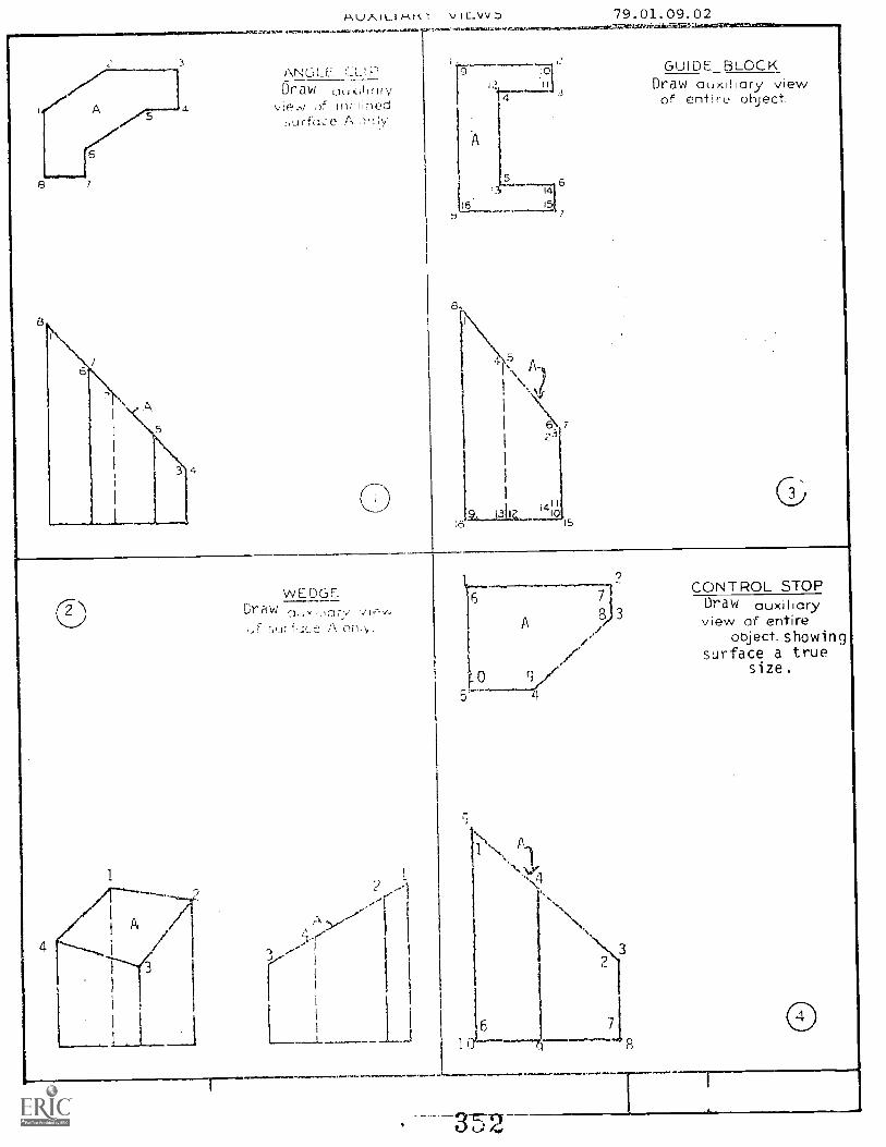
3
4
Au/. at..1"-Are r 3., c...vv.D 79.01.09.02ay. ram.* ,ar waszaavau... c-wlimassarstaraeo,-
ANGLEDraw u,',01(iry
vier, ref IfIr(ined1,LIrfc:,e A
A
6
L +51
IS- 146
8
7
GUIDE BLOCKDraw auxiliary viewof entire object.
C2)
1
WEDGEDraw
Sur A oniy.
Ll
7
A 38) view of entire/ Object. showingjsurface a true
0 V size.
4.0
4

vtew ;-.)f
AD..P.±.31/\13L SI I DL
Draw C.1,1.v.,11:;ry view C1 ,.nt;r,-.:howing true size of !.(1r-foce A
-J
AUXILIARY \/EJS
(6
7
7q-111 119-0
BEJELF D SUPPORTView of
h re .)t.) Act showingtrue iie of surface A.
Hm(lision requiled..1f),110 ri deorees
(1-1U11_)t- L')LC_N. Druvv iewe.iitirt. _)i)j llq
between tOCEIti A , icc t

re.daariwi.Cr.
if
C(.tde: 79. 01, 09, (11. A2 -0
Ouzo Publishcci: 1 -1 n
ktV 1
Ant,ff.) .
SluAC
PER FORMANCE ACT :
OBJECTIVE
To become famil iar with auxiliary views; their LH-,es, and terminology.
EVALUATION PROCEDURE:
Instructor will examine answers for correctness and understanding of concepts
involved. No errors will be llcd on thi s assignment.
RESOURCES:
Basic Technical Drawing, Chapter 12.Mechanical Drawing, Chapter 9 9.5 9.11.
Technir. Drawing, Chapter 8 -- 8.1 - 8.20.
Design Draft'ng, Chapter 10 10.1 10.12.
Basic Drafting Tool s:Drafting Furniture;
P RO C E 1U RE
(e e(See
Unit LEG)Unit LEG)
1. Read the above resource(s).9 Complete :he Fo 1 lwinq exer:,i se and ynur ior oval U te d hy your instructor.
3. Letter de fin i tion for t.h.c, fllowLj :
çj 1. h :
b. Tru-
d.
e. Pr,-)jection:
f.
9.
h. Reference 1.inp:
Ptincipai Ausertor(s): 3. Whee ti ey
3 5
;:Th if 1Aigti igrad 1;1- di, '4_ eckektig

Page ? 79.01.09.01.A2-0
4. An auxilhary view is used to project an inclined surrace (or ilngle) so that
it is shown true shape and
Figure: .49-1
../ \e,
Y
.:cd / ' te \/1 1 -- -- - ..:,1 / N
// \ i.`)---V-.;'.
45°
\ /
/. \-\
1///7
\?) \'`' /Ve
4",fr-
4
2.1
In Unit 4, you found that :irthugraphic views of surfaces are true shape if
the surface is parallel to the place of projection and the L.O.S. is
perpendicular to the surface.
In orthographic projection, each view provides 2 of the true length dimensions,
(height, width, ah.:i depth;.
In auxiliary , 2 true length dimensions are also drawn. One is pro-
jected per.sioular tc the prorile of the inclined surface, and the other
is L,ansferred from an ort;-.4 :Jraphic view. A primary auxiliary may de either
a depth auxiliary, width auxiliary, or a height auxiliary depending upon
which dimension is transfrred. (See Figure .09-2)
5. A step-by-step procedure using a reference line and projecim is shown onFigure 12-r:.' on pag 2!F, in your "Basic Technical Drawing" text.
6 Draw in the reference line (Rp and RA) and the projectors in Figure .09-4.Number the points.
7. Upon completion of this LAP, take the BP test and proceed to the next LAP.
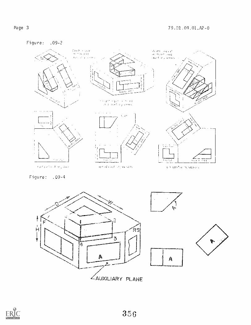
Page 3
Figure: .09-2
79.01.09.01.A2-0
1.,:t1c1
1.7
Figure: .09-4
H RS
3
AUXILIARY PLANE
3 5 6
I \,\71.7.11 I \1.\11..1,0:1.
A
AVAUWAVWMatfa.
FaEiluenfioR
2Vadv4: mile Code: 79.01.09.00.84-0
Dte: Date Published: 9-20-77Revised: 1-16-80
igariderstmz,_ rC1 r-rs ,!a 4, -rr T. av I I T fly T C1.ICEl III INS te4e1 CtS rtJ IILJAILIMNI it I
OBJECTIVE 1:
Given an illustration of a machined object, the student will draw two auxiliaryviews of the object. The primary auxiliary view will contain all hidden lines nec-essary to project the secondary auxiliary view.
OBJECTIVE 2:
The student will be able to draw various auxiliary views that are neat and clean.
OBJECTIVE 3:
The student will be able to draw the three views having all lines accurate.
TASK:
The student will be given an illustration of a machined object. He/she will draw
two auxiliary views and a right-end view of that object.
ASSIGNMENT:
Draw the "Slotted Guide" auxiliary views on the attached sheet.
CONDITIONS:
The drawing ;s to be completed in a typical drafting room setting, using lead on
the attached sheet.
The student will n.-.Jt be rible to use the instructor(s) or other students as a
resource. :),;21.?rt ,se text resources. You are encouraged to determine the
text material ,_,411i"1, to th-i ,.Trormance test, and to utilize thatinformatn is solving this dra4i-ig problem.
3E7Training CoVicei) incv

FAinirFAhwai°
a ram
OVERALL PERFORMANCE:
emckiftt:
Ostg
PERFORMANCE CHECKLTST:
File Coda: 79.01.09.00.B4-0
Date Published
Satisfactory Unsatisfactory
Objective 1:
CRITERIONMet Not Met
1. Both auxiliary views are drawn.
Criterion: All views drawn and no lines missing.
2. All hidden lines are drawn in the primary view.
Criterion: No points missing.
Objective 2:
3. Drawing is neat and clean.
Criterion: (ASA Standard), Technical Drawina, pp. 12 and 22.
Objective 3:- - - -
4. All lines are accurate.
, Criterion: Lines are projected from given views and accurate
F-
1within 1/64".
5. The dr:A i eted in the specified time limit.
Cri ter n: No exceed 6 nc,
----------
L
Student must meet critericn on 4 out of 5 line items to obtain an over-- -
all scot-2 of satifa-:tory.
qc,vp,rc-7 -S1A F11.4.:p

FPO': PEW
BOTTOrA OF DRAWING
'LCTT F. (-1,11DfT
36
rizCM
I0
a)
co
ID
LA
00

File Code: 79.01.09.00.B1-0
Data Published 12-17-75
EihitialkanDate Revised: 1-1580
Pr Gigra [11®0[FrAMZ EIDD@Cild®GOGI @ffltid®
UNIT: AUXILIARY VIEWS
RATIONALE:
When an object has inclined surfaces, the usual views cannot show the true sizeand shape of such surfaces. Therefore, it is necessary to draw a view on a planeparallel to the inclined surface. This view together with the regular views willshow and describe the true size and shape of inclined or oblique surfaces.
PREREQUISISTES:
Unit 79.01.07. Section Views
OBJECTIVES:
Draw auxiliary views to supplement regular orthographic projections.
Identify auxiliary views for illustrated objects.
Identify the characteristics of auxiliary views that supplement regularorthographic projections.
RESOURCES:Printed Materials
Basic Technical Drawing Spencer and Drydon; Macmillan Company, New York.Mechanical Drawina French and Svenson; Webster Division, McGraw-Hill Book.
Company, New York.Technical Drawing Six .h Erlitiy,n; Gieseche. MichPil, Spencer and Hill;Macmillan Company, New York.
Desian Drafting Earle; Addison-Wesley Publishing, London.
As listed in Cow--
Video Cassette Unit 9.
Principd Au Mov : U. he a t y
E-flipment
Audio / i al
3 S1
'fine°

Page 2 79.01.09.00.B1-0
GENERAL INSTRUCTIONS:
This unit consists of five Learning Activity Packages (LAPS). Each LAP will providespecific information for completion of a learning activity.
The general procedure for this unit is as follows:
1. Read the first assigned Learning Activity Package (LAP).2. Begin and complete the first assigned LAP.3. Keep the drawing mounted on the board until it has been checked and
approved by the instructor_4. Take the LAP test if indicated on LAP.5. Proceed to and complete the next assigned LAP in the unit.6. Complete all required LAPs for the unit by repeating steps 1 thru 5.7. TaLe the unit tests as described in the Unit LEG "Evaluation Procedures".8. Proceed to the next assigned unit.
PERFORMANCE ACTIVITIES:
.01 Introduction to Auxiliary Views.
.02 Primary Auxiliary Views of Inclined Surfaced Objects.
.03 Auxiliary Views of Machined Objects.
.04 Right Side, Auxiliary and Auxiliary Section Views.
.05 Primary and Secondary Auxiliary Views.
EVALUATION PROCEDURE:
1. The student takes a multiple-choice test and turns it in for correction.
2. The student takes a unit performance test. Successful unit completion ismeeting the listed criteria for the performance test.
FOLLOW-THROUGH:
Auxiliary views will be drawn throughout the remainder of this course when theyare required for clarity. They will apply specifically to Units 9, 13, and 14 --Auxiliaries, D_-velopmen,-. -,nd Working Drawings.

_--.----ountaln-Plains Education &
onornic DevelopmentProgram, Inc.
Glasgow AFB, Montana 59231
Student:
Date:
File Code: 79 . 01 _09. 00. A2-2(.01.04)
Oate Published: 6/21 /74
UNIT /LAP PRETEST: AUXILIARY VIEWS
1 . The plane that would project true shape in the front view is:
a. plane D.b. plane A .c . plane B.d. plane C.
2. The plane that would project true shape in the right side view is:
a. plane B.b. plane A .c. plane C.d. plane D.
2. The plane that would project true shape in the near view is:
a. clan,:z: E,.b.
pld. plane C.
4. The top and front views of line ab are given below. Th,, correctdirection fr..1- tie line of sight for an auxiliary view in which ab willappear true length
b. H..
aa

Page 2 79. CJ I .09.00. A2-2(.01-.04)
5.
5. The plane at tilt:: bove i li project truu -Thane in:
a. ac auxiliary viEAv.b. the top view.c. the right side view.d. the front view.
6. Line AD --hown above will project true length in:
a. an a,_;:iliaryb. the front view.c. the right side viev .
top vievv,
7. Plane /\;:).C.F-1) hc.ii Fibove project tee :=;11Elpe in:
a.
(7.
of.
the t:fp view.the riqht side vic.vv.an ,:,.uxillary view.
y viewb. a section view.
a orojgcte'i -;lant view.:J. a top view.
rne par:111e1 --urface
3e4
Page 3 79.01.09.00. A2-2(.01-.04)
9. Features that appear distorted in regular views will appear trueshape in:
a. a top view.b. a section view.c. a folded view.d. an auxiliary view.
10. A view obtained by projection on any plane other than the horizontal,frontal, and profile projection planes is known as
a. a bottom view.b. a principal view.c. a regular view.d. an auxiliary view.
79.01.09.00. A2-2(.01-.04)
Ur\ITT/L_AP N LE,A,RY \/TEWS
. D
2 . C3.
5. A5. D7. R
D: )
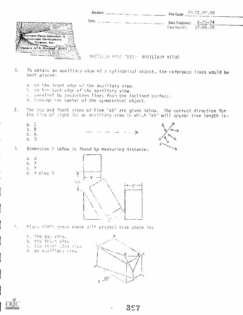
Foun-'--tr;-PLtinsEclucatIon 3.----
:onomic Development --Iillf s..it.,Program, Inc.
/7 ICansigow AF3, Moni.itii- 69231-77:::::Ii I % \ s 'I \'`,:,:-'.-.-'S'-'::"Z 1:-:."---=---.;::-:- ---::::---1---
7(3 0° ODsogh.wt: File Code: 1 0
Dat.a:patepwAislipd: 6-21-74Revised: 1?-05-78
UrifTW' P(1;1' TEST: AUXILIAPY VIEWS
1. To obtain an auxiliary view of a cylindrical object, the reference lines would bebest placed:
(/. on thr: front ed(je of the auxiliary view.()(1 U. 1)4(3' r:dri(! of 1.he auxiliary view.
:idrolltfl to proThction line'.; from the inclined surface.d. '_hr.uugh he center of the symmetrical object.
2 The 1-.op and front vies oF line "ab" are given below. The correct direction forthe iinP of :.ight for u auiliry view in whiLh "ab" will appear true length is:
a. C
5. B
c. AD
3 Dimension 7 below is found by measuring distance:
a.
b. Y
C. Y
d. Y plus Xy
.. H ---\ y Ii...,-
c\
I.', \ \
1
\1
\\:\ \..
I ,
sori ahove will project true shape in:
a. thr. top \fir:4.
b. th fr.)ot
C. Lhed. an alJuil;ari
S
\

Page 2 71..01.1)(1.00
5. A dihedral angle
a. the angle between two intersecting planes.b. the 92° angle formed Hi tho projection lines extending from the edge of an
inclined surface.c. a simile line indicating where two separate planes intersect.d. obtained by a :,s(JurHg a oirection of sight perpendicular to the line of
intersection h,-.tween two flane--
6. To get the edne view i).1 a u'dne:
a. assume a direction of sight which will allow you to see the shape of theplane.
b. g..t the end poipt view r any line in that plane.a. a njrnn a direction of a rht perennicular tei the point view of a line in
that plane.the, men t COWilnn prlftice is to revolve the ehject until the plane surface
jr,
7. It is possible to eliminate one or more regular views by the use of:
a. an auxiliary view.b. a top view.c. a projected view.d. an end view.
P. A secondary auxiliary view is:
a. a view which is riot as important as other views.h. the accord view drawn from the right side view.c. any auxiliary view projected from a primary auxiliary view.d. often used to show Lk;' edge view of on irial inch surface.
9. Features soot appear distorted in regular views will appear true shape in-
0. A top view.h. a se,iion Vicc. a folded. a,. AJxiliary
10. A view obta;ned by ;-,rH,:!ctin on any plane other th the horizontal , frontal,and profile projectinn Hanes is known as:
a. a bottom vie./.
b. a principal view.c. a regularP. an auxilia / view.
8

UNIT/LAP POST TEST ANSWER '<FY: AUXILIARY VIEWS
1. D
2. A
3. B
4. D
5. A
FJ B
7. A
2. C
9. B
in. D
3C9
7(:).01.0().00

FHB Code:79.0l.09.01: A2-2
.. Date Publishod:
L,.) TEST: IiRODUC ION TO AlIXTLIARY VIEWS
Auxiliary views are used to sow tAe size of a surface which:
1-16-79
is parallel to one of the standard planes of projection.b. is perpendicular to the top, front or right side plane of projection.c. is at an angle other than 900 to the standard planes of projection.d. appears as a line in two of the standard planes of projection.
The Position fo- one of the two required reference lines in Figure 1 is:
a. at a 30° angle to t11e edge view of surface C.b. p:).,aliP1 to the projection lines extending from the edge View of surface C.c. perpendi._:oar to the edge of surface fl.
d. parallel to the edge view of surface C.
Fin.
C
r.)
3. A second reference line in Fig. 1, would be located:
a. parallel to th7 edge view of surface D.h. perpendicular to projection lines between the two givenc. at any angle projeqtinR fr,(11 the right side view.d. a second reference line is not needed.
4 Reference lines are:
a. primarily used to space the auxiliary view a sufficient distance away fromthe object.never J.3.:21 in ortilpficEThL ;)colection.
C. ore the lines from which you measure when transferring a distance fr,m oneview to another.
d. not to be drawn so that they cut through an object.
1.71 91) r f-9?,Pqr
V
. 37c 1-4 ;F::,
3
rc;

Page 2
5. In drawing a depth auxiliary view, you will need:
a. three views of the object.b. the too and right side views.c. the front and rear views.d. the front view and one view showing depth
6. Which of the following shows a width auxiliary view?
79.01.09.01: P.2-?
7. When drawing an auxiliary view of an entire object which features an inclinedsurface:
a. you will see thr true size and shape of each surface.b. you will see only those surfaces closest to you in the true size and shape.
those surfaces which are not parallel to the reference line will he distortedin size and shape.
d. measurements from all of the surfaces shown in this view would be accurate.
8. The views required to make a height auxiliary view are:
a. ton and front.b. front and right side.c. top, front and right side.d. front and left side.
371
Page 3 79.01.09.01:A2-2
9. Hidden lines An auxiliary views are:
a. preferred to usinc an auxiliary section.b. never used.c. used in depth auxiliary views only.d. used for clarity of object shape.
10. Auxiliary views are:
a. never used 1:o replar: a vicod o7' an objed.
D. often extra and unnecessary.C. often necessary for dimensioning.d. drawn to show the true shape of the entire top, front or right side view.

79.01.09.01:A2-2
LAP TEST ANWEP. KEY: INTRODUCTION TO AUXILIARY VIEWS
373

File Code:79 01 10 00-A2-1
Famihr Clete Published: 2-8-791111
LIVEntr's42' Revised: A-14-79
AniMtatin rvi
EPIC'C91 tut] 5-t), (;)_j Ls' %.,c ph. d @Fp) @ Psi ®UUT: TPIPLATES
pATIONALE:
Templates are used extensively ir he dr:.Iftiriti field. Templates are used to speedup drawing and ,:iake repetit;ve draing easier. /1 knowledge of some of the many
fit::m(yr r SOfl
PPEHGH1STTES:
Unit 79._51.09 -- Auxiliary Views.
Students will become Familiar with many of the templates available for the draftingareas. Students will learn to use templates quickly and efficiently. Line weight
and neatness will meet ASA standards.
RESOURCES:
Printed Materials
Alvin catalogSelby's catalogTeledyne Post catalogDietrich Post catalog
Basic Technical Drawing. Spencer and Drydon, Macmillan Company, New York, 196:1.fngineerinaDrawing_ and Graphic Technology. French and Vierck, Eleventh Edition,
McGraw-H;11 Book CL.opany, New York, 1973.Mechanical L7awi- 'rrench and c-..,,,nson, Webster Division, McGraw-Hill Bock Company,
New York , PAR.Technical Drawing. Gieseche, Mitchell, Spencer and Hill, Sixth Edition, Macmillan
Company, New York, 1974.Design Drafting: Earle, Addison-Wesley Publishing Company, Menlo Park, CA.
Equipment
As given in course LEG plus assorted templates.
Audio/Visuals
Video cassette for template useage.
PrinciptiAtnho00: J. 'Wheatley, S. Vosen
374
Falb/ RAM Cenanie, tine.
Page 2 79.01.10.00:A2-1
GENERAL INSTRUCTIONS:
This Unit consists of four LAPs. Each LAP will provide specific information for itscompletion.
The general procedure for phis unit is:
1. Read the Unit LEG.2. Proceed to the first LAP.3. Complete the LAP.4. Take the LAP test iF indicated.5. Pcoeat steps 2 thru 4.6. Take the Performance Test.7. Take the Unit Post Test.
Proceed to the next Unit.
PERFORMANCE ACTIVITIESJLAPs).:
1. Introduction to Template Use2. Using a Template to Draw an object.
3. Using a Template to Provide Plan and Elevation Views.4. Using a Template to Draw Symbols.
EVALUATION PROCEDURE:
1. The student takes a multiple-choice unit post test and turns it in forevaluation.
2 The student takes a performance test. Successful unit completion is meeting
the listed criteria for the performance test.
FOLLOW-THROUGH:
ASA Standaiis of neass and line work will be observed throughout. Begin first
LAP.

pERFoRmpArjE. AcTonry; li,::::-LJduct. ion to Tempi ate Use
ObJEC-T1V:
79.01.10.01:A2-0rill Cod.
Claw ,Pub!isk d:? -8-79
r
11120mt:
Data:
BA, L.
Student will become aware of the variety of templates available. Student will draw
a ch Fi cat i on chart .
EVALUATION PROCEDURE'
In crub t-.or wi I examine cl 2ss i 7=i cation chart to check that al 1 information is in-
cluded a:,ci 1 inc work and lettering is acceptable. There i is no LAP test. Student
will take Unit Post Test upon completion of all unit LAPS.
RESOURCES:
Technical Drawing_. Page 715 Article 26-24.
Engineering Drawina and Graphic Technology. Page 433 Article 19Page 726 Article 38
Mechanical Drawinq. Page 390 -- Article 24-15.
Alvin Catalog
Drafting tools and equipment as listed in LEG.
PROCEDURE :
1. Read tho reocur:...,:, listed.
2. PreparE a ::'.7.'iLation chart containing the following information.
I Draftin; AidsA. Transfer materials
1. pressure2. heat3. cut out films4. trees
B Templates1. stencil s
?. burnishers3. guides (scribing)4. outline templates
a) symbol s
h) shapesc).objectsd) letters
3. The coart will be done in lead on a sheet of size "A" vellum4. Have the chart evaluated and then go on to the next LAP .0 ?.
Principal Au t hn r ( 1 Vn sen INammllur petiglimo4 glosattow imp0 . 0

r0g312201 g 2'1kS d
Coda'7'1.01.10.02 :A2-0
DOW Publi.;lied-2 -R-79
Revised: 8-14-70, ,
:111. \47 rt,In c
Ow:
PERFORMANCE ACTIVirl: Using e Template to Draw An Ohject
OBJECTIVE:
The student wi ll draw several objects correctl y using an outline template.
EVALUAT f ON PROCEDURE:
The instructor will evaluate the drawings to see i f they are drawn correctly andneatly. The drawing must be correct i.efore the student proceeds to the next LAP.There is no LAP test.
RESOURCES:
Mechanical Drawing -- Unit 12.Technical Drawing -- Unit 13.En_g_ineerin_g_ Drawing_ and Graphic Technology Unit 15.Design Dra ft i ng Unit 12.Basic Technical Drawing -- Unit 14.
Drafting tool s and equipment as 1 isted in LEG.
PPOCEDURE
1. Read the resources listed.2. Using the appropriate templates, draw the required fasteners. Use lead on a size
"A" sheet of drawing paper.L17,1,' h;TH;lat 1 C threbl S1/111h01 s on the fi rst drawings and simpl I Fi ed threaded symbol son the reTainii.:.
Principe Author(%) : S. Vo sell , J. 4Iheatley
r"7,
S., IV 411

Page 2
1
1
9/16 x 214-24 UNIFL HD Cap Scrcw
41 "4f ' A I r
x 2 FILL ;IDMachine Screw
4. Have your drawing eval uateo and voceed to the next LAP.
373
79.01.10.02:A2-0

File Coda79.01. 10 03-A2-0
Date Publithed: 2-8-79
Revised: 8-14-79
ei 4' ActivLity Pack 'a
Date:
PUs i ng a Tempi ate to Provide Plan and Elevation Views
ER rORMANC E ACTWIT Y:
OBJECTIVE:
The student will draw the requ:red plan and elevation views using the appropriate
templat,-
EVALUATION PROCEDURE:
The instructor will examine the views to see that they al e accurate, correct, and neat
There is no LAP test.
RESOURCES :
Design. Drafting, paragraph 19-30, page 535.
Drafting tool s and equipment as listed in LEG.
PROCEDURE:
1. Read the resource l isted.2. Draw a pi an and elevation view of the bathrooms shown in A and D. Each bathroom
w i l l be 6rawn on a size "A" sheet with lead.
Have the drawi ng Hated and proceed to the next LAP.
HINT: El e a re nLuEr,11y shown from the door side of the room.
Principal Auttlor(s): . Vosen , J. Wheati
,
1511.....J1127 TilmuhAish:raia iillaktagoaro igaeg

PERFORMANCE AC,' Int ri"
jFC7IVE:
7.)
1:16 Cs& 79.01.10.04:A2 -0
Revised: 8-14-79
1 31!
i.l.A; ;"V %A.
n
(4:;:j1 ESI .14'4 %4
COW
1;Sifij .,?mplatc.! to Draw Symluols
The student will d,Jvi the assigned schematics using the appropriate templates.
EVALUATION PROCEDURE :
The Ct.O di 11 the to iasnre that Vley are accurate and neat.no LAP ::Pst.
Mechanical Drawing -- Chapter 18.Basic Technical Drawing Chapter 22.Technical Drawing -- Chapter 21.Engineering Drawing and Graphic Technology -- Chapter 20.
Drafting tools and equipment as listed in the LEG.
PPOCEDUftE:
1. Read the r2sources listed.
2. Draw onP of the circuit diagrms on the back of this page.
3. Th.: diagram will he done in lead on a Size "A" vellum to twice stale
4. Make a diazo print for the instructor's evaluation and proceed to the PerformanceTest.
PrinciimiAutho40: S. Posen, J. Wheatley
350Witamihr Csubtr., Oat_
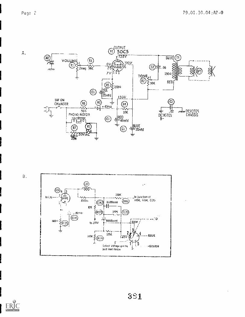
Page 2
A.
L.
,-- \OUTPUT
500571725V
170V6
ov2-5
7V
®`111i20mfd
SW ONCHANCER
56nPHONO MOM R
to 1_36
150o
130V
10K
EDLi'40mfc1
,L2l0JEffid
79.01.10.04:A2-0
46-
LO)
Anri
1
02
DENOTE(/ OcEHlfiOssTiEsS
B-
150K_to junction of
10kOmnif RIG'."159' R16), 0135
12K
1739:-K
to 270v
?SOK
\o-
I20K140V
rSelect Voltege giving53st Rod Rrster
OV
UUE
-GREEN

FA/A14:Educatiltiz
et1P4341t:
Dote:
§14,13N'An UN11. Th-r/P(lST TEST:
File Coda:79.01.10.00:B2-2
_. note Published: 3-.8 -79
TEMPLATES
1. In an actual dra Ft in g situat ion templates are used :
a. extensive)b. occasional 1 y
c. rarelyd. not at al
2. The ma in reason For tempi ate use i s:
a. accuracy c. speed
b. l n7. ness d neatness
3. Templates are oftrn used on:
a. precision work c. perspective drawings
b. repetitive work d. border lines
4. Cut-out templates can be used with:
a. ink, 1 ead and burni si..=2rs
ruling pens, pencils and burnishersc. LeRoy pens, lead holders and ruling pensH. Pencils, lead holders and automatic reservoir pens
5. Templates can be used to draw:
a. objectsb. symbol s
c. diagrams0. c"" of these
2
ephp rrAfikp fz,-)..4A.I:if,4itija 9 tztids k),..o

UNIT PRE/POST TEST ANSWER KEY: TEMPLATES
1. A
2.
3. B
5. D
3 3
79.01.10.00:B2-2

(-1((..1.,c1(.(1enEcvn, roc
In-2@0[1017J1LTI. 1GG(nc.
(.L4 1L W A 'a Mill-IL% b 9 2
FileCode: 79.01.11.00.A2-1
Dma Publishyd: 12/17/75
kevis6, 8-13-79
)WT' ,;S
Jhe ou rpoa of H: LS Ui i to st.udy a system of drawing which enables-!r-11(77.-1:, Yc, ;LOW H701 aL. and in !-;nch a way that the :)rinciple
7'if.'tc.,Liai views are nsed in technical illustra-
s. dr riOn(1 !).1.0,1 show detai l. which sometimes
Dr..iw a iAct.:ofial drawing using rive types of pictorial projections.
!,:he ch,aracteriszi,.:s of L.1)e rive types of pictorial projections.
P.E.S()URCEf.;:
Printed Materials
Basic Tctchniodl DI-awing. Spencer s Dryden, Ma's!millan Company , Now York.
7,::nuineering Drawim_j and (-:r,2.j)iii.c Technolo,Ty. Frmich Vierck, Elevonth Edition,McC;rJw-Hill. Bock Company, Nt,w York.
FicawHq. Fr 7,(:11 Wehrit..r.r Division, McGraw-Hi 11 Pock Company,
Mw V0rtTechnical Edition, Gieseche, Mitchell, Spencer & Hill, MacmillanCompany, New ,
Dt!si,jn Li. faces California.
Equipment
Draftirl Tr--)(7)1,;: 'Jen (Ylirse 1_,EC;
Slool, draltingcirafting
Iideo cstte on UhL 11.
Principal Author(s):
(with T-square, Parallel roleand/or drafting machine)
Audio/Visual
I I t ,t i , , i I 1 1.y , \.',,11
Page 2
GENERAL INSTRUCTIONS:
79.01.11.00.A2-1
This unit consists of five Learning Activity Packages (LAPs). Each LAP will
provide specific information for completion of a learning activity.
The general procedure for this unit is as foljows:
(1) Read the first assigned Learning Activity Package (LAP).
(2) Begin and complete the first assigned LAP.
(3) Take and score the LAP test.
(4) Turn in the LAP Lest answer sheet.
(5) Determine the reason for any missed items on the LAP test..
(6) Proceed to and complete the next assigned LAP in the unit.
(7) Complete all required LAPs for the unit by following steps 3 through 6.
(8) In this Unit, there are some LAPs that have tests combined with other
LAP tests. These combined tests are taken after completing the last LAP
covered by the test.
(9) Take the unit post test as described in the Unit. LEG "Evaluation Procedures".
(10) Proceed to the next assign.:;:q unit.
PERFORMANCE ACTIVITIES:
.01 Isometric Drawings
.02 Cavalier Drawings
.03 Cabinet Drawings
.04 One-Point Perspectives
.05 Two-Point Perspectives
EVALUATION PROCEDURE:
When post testing:
1. The student takes a multiple-choice post test and turns it in for correction.
2. The student takes a unit performance test. Successful unit completion is
meeting the criteria for the performance test.
FOLLOW-THROUGH:
Eit.:qin the first assigned Learning ActiviLy Package (LAP) in this unit.

ountain-Plains Education &onomic DevcluPinent
Glasgow AFB, Mon auk 69231
79.01.11.01.
Student. File Code 1 1 on AP-2
Data: Date Published: 6 /21174
UNIT PRETEST: PICTORIAL DRAWINGS
1. The angle between the isometric axis is:
a. 90 decrees.b. 120 degrees.c. 30 degrees.d . 45 degrees.
2. The type of line that is usually omitted from isometric drawing is:
a. visible.b. hidden.c. center.d. circles and arcs.
3. Measuring of angles in isometric drawings is:
a. not possible since angles do not show in their true size.b. done with the compass.c. done with the protractor.d . done with the triangles.
4. In an isometric drawing, circles will appear as:
a. ellipse -.h. p-..
circles.d. hyperbolas.
5. The dimensioning method to use on an isometric drawing is:
a. bottom.b. aligned.c. unidirectional.d . side.

79.01.11.00. A2-2
79.01.11.02.79.01.11.03.
6. In an oblique drawing, the number of principal views shown is:
a. three.b. two.c. one.d. four,
7. A cabinet drawing is a type of:
a. a oblique projection.b. axonornetric projection.c. orthographic projection.d. perspective drawing.
8. When the projectors make a 45 degree angle with the plane ofprojection, the drawing is:
a. an orthographic projection.b. a cavalier projection.c. a dimetric projection.d. a trimetric projection.
9. On an oblique drawing, the longest side of the object is placed:
a. vertically.b. perpendicular to the plane of projection.
parallel to the plane of projection.d. along thE, -eceding axis.
10. When measuring in an oblique drawing, the scale to use is:
a. an ordinary scale.b. any of these.c. a metric scale.d. an engineers scale.
3S7
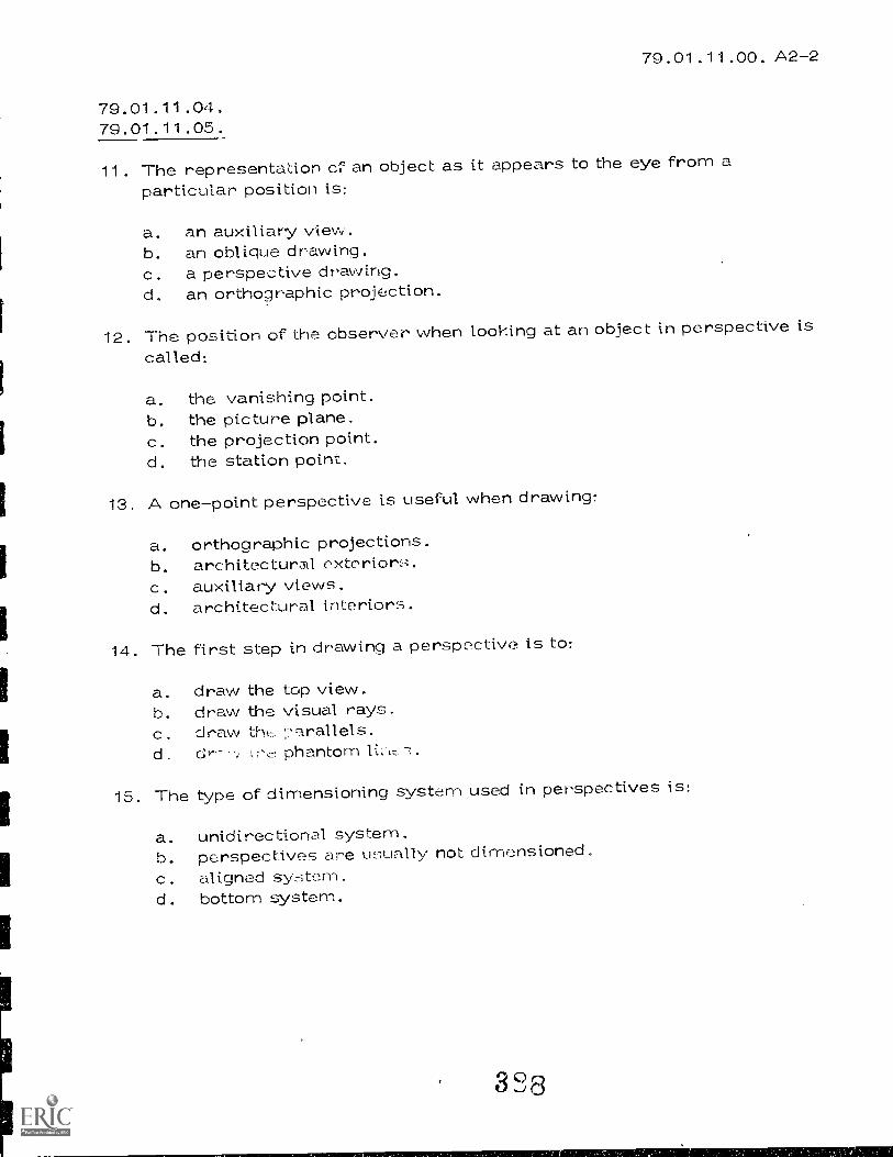
79.01.11.00. A2-2
79.01.11.04.79.01.11.05.
11. The representation of an object as it appears to the eye from aparticular position is:
a. an auxiliary view.b. an oblique drawing.c. a perspective drawing.d, an orthographic projection.
12. The position of the observer when looking at an object in perspective iscalled:
a. the vanishing point.b. the picture plane.c. the projection point.d. the station point.
13. A one-point perspective is useful when drawing:
a. orthographic projections.b. architectural extc.,rior;-1,c. auxiliary views.d. architectural interiors.
14. The first step in drawing a perspective is to:
a. draw the top view.b . draw the visual rays .c. draw thed. phantom
15. The type of dimensioning system used in perspectives is:
a. unidirectional system.b. perspectives are usually not dimensioned.c. aligned system.d. bottom system.

UNIT PRETEST ANSWER KEY: PICTORIAL DRAWINGS
LAP
01 1. B2. B3.4. A5. C
02- 6. A03 7 A
8. 13
9. C1C). n
04- 11. C05 12. D
13. D14. A15. 9
3S9
79.01.11.00. A2-2
File Code: 79.01.11.01 .A2-0
Oato Published. 12/18/75
Revised: 1-3P0
'74\ 1.'7,2 fiery4 ck a
PER FORMANCE ACTRfl T :Isometric Drawings
Stu :
Dom:
OBJECTIVE:
Draw an isometric working drawing of a machined object.
EVALUATION PROCEDURE:
Instructor will examine drawing for accuracy, neatness, line work, and lettering.
No more than three errors will be allowed.
Correct answer at least 8 out of 10 items on a multiple-choice test that measures
achievement of the °bloc:Live for this LAP.
RESOURCES:
Design Drafting, Chapter 9 (Paragraphs 9-1 thru 0-18).
Basic Technical Drawing -- Chapter 16 (Paracyaphs 16-1 thru 16-17).
Mechanical Drawing, pp. 193-202.Engineering Drawing and Graphic Technology, Chapter 6 (Paragraphs 1 thru 15) .
Basic Drafting Tools: (see Unit. LEG)
Drafting Furnicure: (bee Unit LEG)
PROCEDURE:
1. Read the above resource ok(s).
2. Draw 'h isomEur working drawing from one of the following drawings:
"Basic Tec: .1)ci. 122, Drawing 7-31-4) (Pg. 125, Drawing 7-46)
(Pg. 12, Drawing or (Pg. 126, Drawing 7-52) .
NOTE: Use the problem that you have selected for this LAP throughout the
remainder of the drawings for this unit.
The drawing w;1) he dnne in pencil on a () D 11' tTheoL of drawing paper!
3. Have the instructor evaluate your drwin.
4. Take and score th LAP Lf:).st.
Procood to tho itot LAP.
Principal Author(s): C. We t_ t.e r 1_ rig , WheatLey, S. Vosen
oi,;1/2rIttv CoyAveful Eint.ea
0_ ;p.,At. zoo
390

ounteln-Plelns Educationonomic Development
Program. Inc.
Glasgow AFB, Montana 69231
Student: File Code: 29-01 . 1 t.01, A2-2
Date: Date Published: 6/21/74
LAP TEST: ISOMETRIC DRAWINGS
1. In an isometric drawing, angle A shown above is:
a. 100 degrees.b. 115 degrees.c. 30 degrees.d. 120 degrees.
2. In an isometric drawing, angle B shown above is
a. 60 degrees.b. 25 degrees.c. 20 degrees.d. 30 degrees.
3. In an isometric drawing, the number of principal views shown is:
0. two.c. one.d. three.
391

Page 2 79.01.11.01. A2-2
4.An isometric dr "awing of the object shown in Figure A should look like:
D any of these.
5. Measurements on an isometric drawing should be made:
a. vertical or horizontal.b. with a metric scale.c. parallel to the isometric axis.d. so they are reduced by four-fifths.
6. An example of a pictorial drawing is:
a. section.b., isometric.c. auxiliaryd.
fizatrs-A
7. The type of line that is usually omitted From isometric drawing is:
a. visible.b. hidden.c. center.d. circles and arcs.
3 C. 2

Page 3 79.01.11 .01. A2-2
8. In an isometric drawing, circles will appear as:
a. ellipses.b. parabolas.c. circles.d. hyperbolas.
9. The first step in making an isometric drawing is:
a. lay out the top view.b. draw the isometric axis.c. determine the spacing between the three. views.d. draw the circles and arcs.
10. The dimensioning method to use on an isometric drawing is:
a. bottom.b. aligned.c. unidirectional.d. side.
323
LAP TEST ANSWER KEY: ISOMETRIC DRAWINGS
1. D2. D3. D4. B5. C6. B7. B8. A9. 9
10. C
3 L' 4

PERFOAMANCE ACTIVirt (bLLuuo Drawings:
Filo Codo*79.01.11.02-A2-0
Dmo Publkhed.11/06/74
Revised: 08/08/78
AC109Mci
_
Cavalier
Draw a cavalier working drawLng of machined obiect.
t.'VATU,rtTIC,111 PROCEDURE:
Eis fL,}g
will examine drawing Fir accuracy, neat es linowo)1-L, and lettering.
No more than threç ! errorH; will be Lillowed.
RESOURCES:
Basic Technical Drawiha, Chapter 16 (Paragraphs 16-18 thru
Design Drafting, Chapter 9 (Paragraphs 9-19 thru 9-27).
Engineering Drawing and Graphic_Technoloay_, Chapter 6 (Paragraphs IS thru 23).
PROCEDURE:
1. Read the pages from the above resource book(s).
Draw a cavalier working drawing of your assigned problem from LAP 0]. Draw
the receding axis at 45° Use a 9 X 12 sheet and lead.
3. Turn in yc,ur draing:-. to the instructor for evaluation.
4. Comple,.. LPN: u(.2ore ta;.irg LAP Test_
5. Proceed to the Heir LAP.
Principal AtithOr(s): C. Wet Lerl , J. Whoa t I ey , S. Vosen
t71:41,mr4,;ii'vAi414S:t.,,PliU
3 L'
g1 Ps
ParnE-A

File Code: 79.01.11.03.A2-2
OmsPulMillted. 11/06/74
Revised: 08/08/78
4,1<
41i:1 dnN
10'11111, VY Peck
PERFOnMANCE ACTIVriv: Oblique Drawings: Cabinet
013jECTIVE:
Draw a cabinet working drawing of a machined object.
EVAUiATION PROCEMIRE:
StudT,:rz:
ge
pritw
Instrhtor will cx mine drawing for accuracy, neatns, linel,:ork, and lettering.
No more an three e-?:rorY: will be allowed.
RESOURCES:
Basic Technical Drawing, Chapter 16 (Paragraphs 16-18 thru 16-27).
Design Drafting, Chapter 9 (Paragraphs 9-19 thru 9-27).
Engineering Drawing and Graphic Technology, Chapter 6 (Paragraphs 24 25).
PPOCEDIIRE:----------
1. Read the pages from the above resouree book(s).
2. Draw a cabinet woking drawing of' your Assigned problem Crom LA's 01 r; 02.
Draw the receding Axi S at 45(). Use a 9 12 sheet and lead.
3. Turn in your. rclwi:,(Ts to the insLiuctor for evaluation.
4. Take n: T 1tor Lin., 02 and 03.
r_ 'Proceed to th;r:i next LAP.
Principal Author(s): Wetterlinq, 3. Wheatley, S. Vosen
3' 6Wt.",Prsi-4.447.1T
;Apply-,titAN

ountain-Plains Education ezonomlc Development ---I
Program, Inc.
Glasgow AFB, Montana 59231{
Studeut:
Date
File Code: 79.01 11 02 A9 -279.01.11.03. ,A2-2
Date Published: 6Z21/74
LAP TEST: CAVALIER DRAWINGS/CABINET DRAWINGS
1. The receding axis in an oblique drawing is drawn at:
a. an angle of 120 degrees to the other axis.b. 90 degrees to horizontal .
90 degrees to vertical.d. any angle between 15 degrees and 75 degrees.
2. In an oblique drawing, the number of principal views shown is:
a. three.b. two.C. one.d. four.
3. A cavalier is a type of:
a. oblique projection.b. axonometric projection.c. orthographic projection.d. perspective drawing.
4. A cabinet drawing is a type of
a. oblique piz...jection.b. a.:-_,..,:yretric proje.cttoi,.
orthographic projection.d. perspective drawing.
5. In oblique projection, the angle that the projectors make theplane of projection is alwa,./s:
a. an oblique angle.b. parallel.c. perpendicular.d. 120 degrees.
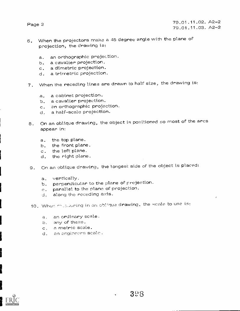
Page 2 79.01.11.02. A2-279.01.11.03. A2-2
6. When the projectors make a 45 degree angle with the plane ofprOjection, the drawing is:
a. an orthographic projection.b. a cavalier projection.c. a dimetric projection.d. a trimetric projection.
7. When the receding lines are drawn to half size, the drawing is:
a. a cabinet projection.b. a cavalier projection.c. an orthographic projection.d. a half-scale projection.
8. On an oblique drawing, the object is positioned so most of the arcsappear in:
a. the top plane.b. the front plane.c. the left plane.d. the right plane.
9. On an oblique drawing, the longest side of the object is placed:
a. vertically.b. perpendicular to the plane of projection.c. parallel to the plane of projection.J. along the receding axis.
10. When in cbl'que drawing, the scale to use is:
a. an ordinary scale.b. any of these.c. a metric scale.d. an engineers scale.
3,- 8

79.01.11.02. A2-279.01.11.03. A2-2
LAP TEST ANSWER KEY: CAVALIER DRAWINGS /CABINET DRAWINGS
1. D2. A3. A4. A5. A6.7. A8. 3'9. C
10. B

FA 14iEheari
Ingram e ni Activity Packag
Fits Code.79.01.11.04 . A2-0
OmPublidld. 12/18/75
Revised: 9-13-79
Slurhsnfi:
Ono:
PERFORMANCE ACTIVITY:One-Point Perspectives : Orthographic Method
OBJECTIVE:
Draw a one-point perspective of a machined object using the orthographic method.
EVALUATION PROCEDURE:
Instructor will examine drawing for accuracy, neatness, linework, and lettering.
No more than three errors will be allowed.
Successful completion of this LAP is determined by correctly answering at least
8 out of 10 items on a multiple-choice test that is combined with "Two-Point Per-
spectives" LAP test and is taken after completing that- LAP.
RESOURCES:
Design Drafting, Chapter 18.
Basic Technical Drawirlg, Para. 16-28 & 29, pp. 321 & 322. Paragraph 16.32,
Pg. 325 & 326.Mechanical Drawing, pp. 208-210.
Engineering Drawing and Graphic Technology, Chapter 6 (Paragraphs 29 thru 34).
Basic Drafting Tools: (See Unit LEG)
Drafting Furniture: (See Unit. LEG)
PROCEDUE:
1. read the
2. Draw a one-point perspective of the drawing from LAPil 0.1, 02, & 03. Use
pencil and a 12 X 18 sheet.
NOTE: Do not movt2 or remove the completed drawing From yL,o) hoard.
NOTE: You will n,;(-2A 2 orthographic views showing width, hei,:nt, and depth.
3. Have the instructor evaluate your drawing.
4. Wait unti.1 completing LAP 05 to take LAP Test.
Proceed to
Principal Authorls): C. Wetterling, J. Wheatley, S. Vosen
en5117,Tioti
0
EnE.N4 nastit,

FamilyEducailoRPregMiN rnRn (.7f4 c 3 F 7 'd c, k a e
File Cade:79.01.11.05.A2-0
Date Puirlithed-12/18 75
Revised: 8-13-79
Stuert:
Ogta:
PER FOPMANCF ACTIVITy:Ortpoyraphi c Method
OBJECTIVE:
Draw a two-point perspective of a machined object: using the orthographic method.
EVALUATIOU PROCEDURE:
Instr,,-.ct_ol. will examine the drawtnsi for accuracy, neaN-les, linewolk, and lettering.
:10 more tan three 1-:rror will bc, allowed.
Successfully complete at least fl out of 10 items on a multiple-choice te:;t.
RESOURCES:
Design Drafting, Chapter 18.Basic Technical Drawing, Chapter 16 (Paragraphs 16-30 16-31).
Mechanical Drawing, pp. 211-217.Engineering Drawing and Graphic Technology, Chapter 6 (Paragraph 29 thru 34).
Basic Drafting Tools: (See Unit LEG)
Drafting Furniture: (See Unit LE(;)
PROCEDURE:
1. Read "he resour,,!(A.
2. Draw a tw-;:f)iut o t drawing from previotn; LAPs. 1' 1e pencil
and a 1.2 Y 18 shf.:et.
NOTE: Do not or remove your completed drawing from your board.
NOTE: You will need 2 orthographic views showing with U, and depth.
3. Hove the instruct,,r nvaluate your
4. Take the LAP test.
5. Proceed to Pfll-formtic Test.
Principal Author(s): C. Wetterling, J. Wheatley, S. Vosen
51's1r1
o
:34t;;;45nhi, !Afz4
(1 '61 cl :J GiV

ountaln-Plains Education &onornIc Development
Program, Inc.
Glasgow AFB. Mon no-- 59231 ----,
79.01.11.04. A2-2
Student: File Code: 79.01.11.05.A2-2
Date: Dote Published: 8/13/75
LAP TEST: ONE-POINT AND TWO-POINT PERSPECTIVES
1. The representation of an object as it appears to the eye from aparticular position is:
a. an ao.ixiliary view.b. an oblique drawing.c. a perspective drawing.d. an orthographic projection.
2. The plane upon which a perspective view is drawn is called:
a. the perspective plane.b. the projection plane.c. the picture plane.d. the orthographic plane.
3. A one-point perspective is useful when drawing:
a. orthographic projections.b. architectural exterior,.c. auxiliary views.d. architectural interiors.
4. The First step in drawing a perspective is to:
a. top view.b. draw the visual rays.
draw the parallels.d. draw the phantom lines.
5. The type of dimensioning system used in perspectives is:
a. unidirectional system.b. perspectives are usually not dimensioned.c. aligned system.d . bottom system.
402

79.01.11.04.A2-279.01.11.05.A2-2
LAP TEST ANSWER KEY: ONE-POINT AND TWO-POINT PERSPECTIVES
1 . C2. C3. D4. A5. B

1,"Education &
1
Dleggow AFB, Montana 59 231
....\.,s.t.P....rOftfaal. Inc.onomlc Development
UNIT PERFORLANCE TEST: PICTORIAL DRAWINGS
atudant File Code: 79.01.11.00. A1-5
Dem Date Publisned 11/06/74
Revised: 08/08/78
OBJECTIVE 1:
Given a machined object, the student will be able to assemble the five types of
projections into a balanced pictorial representation.
OBJECTIVE 2:
The student will be able to draw this pictorial representation in ink on the
plastic film.
OBJECTIVE 3:
The student will be able to trace the representation accurately and properly.
OBJECTIVE 4:
The student will be able to reproduce this drawing by the Diazo
TASK:
process.
The student will make a finished drawing and Diazo print of the five types of
projections.
ASSIGNMENT:
Draw the objects used in LAPs one through five in ink on a 12 X 18 sheet of Mylar
and label it correctly. make aDiazo print of the drawing.
CONDITIONS:
The drawing is to be completed in the drafting room, using the necessary facilities.
The re:3ourceE., are li:-;ted in the UniL LEC - The inructor, or other :students,
Indy not. be u5-;ed re!;onret.,!;.

FamilyMiradaProgram
StSitstit:
Doe*
PERFORMANCE CHECKLIST:
OVERALL PERFORMANCE: Satisfactory
79.01.11.00:A1-5File Code:
Gem Published:11-6-74
Revised: 8-17-79
Unsatisfactory
CRITERIONMet Not Met
Objective 1:
1. All five types of projections are shown in their entirety.
Criterion: No lines missing.
Objective 2:
2. The drawing is inked properly and is clean and neat.
Criterion: (ASA Standards), Technical Drawin , pp. 12, 20, 22.
Objective 3:
3. All line work is accurate.
Criterion: All line measurements within 1/64" of scale.
Objective 4:
4. The Diazo Print will be legible.
Criterion: The drawing will reproduce evenly and background will be
white.
5. The drawing will be completed in a specified time limit.
Criterion: Not to exceed 6 hours.
The student must meet 4 out of 5 to satisfactorily complete.
A1'1 r-
Frollw Ttinkzing Caste?, coo

ountain-PL eins Education &onornic Development
Program, Inc.-
Glasgow AFB. Monte ---"" 69231 -\' -
79.01.11.01.
Student: File Code: 79.01. 11.00 . B2-2
Date: Date Published: 6/21/74
UNIT POST TEST PICTORIAL DRAWINGS
1. When measuring in an isometric drawing, the proper scale to use is:
a. an isometric scale.b. a metric scale.c. an ordinary scale.d. any of these.
2. The only type of object that can be drawn in isometric is:
a. an object without arcs.b. a rectangular prism.c. an object that is machined.d. any type of object.
3. The angle between the isometric axis is;
a, 90 degrees.b. 120 degrees.c. 30 degrees.d. 45 degrees.
4. The tools that are used to draw isometrics are:
a. T-square_ and 45 degree triangle.b. and 30 ciegr,?:- x 60 degree triangle.
T-square and proportional dividers.d. T-square and protractor.
5. Measuring of angles in isometric drawings is:
a. not possible since angles do not show in their true size.b. done with the compass.c. done with the protractor.d . done with the triangle.

79.01.11.00. B2-2
79.01.11.02.79.01.11.03.
6. .cavalier drawing of the object shown in Figure 9 should look like:
A
any of these.
Figure B
7. A cabinet drawing of a cube should look like:
A B
C
8. Circles and arcs in oblique appear true- .:ize true-shape in
a. the front plane.b. the left plane.c. the right plane.d. the top plane.
9. A cabinet drawing is a type of:
a. oblique prbjection.b. axonornetic projection.c. orthographic projection.d. perspective drawing.
407
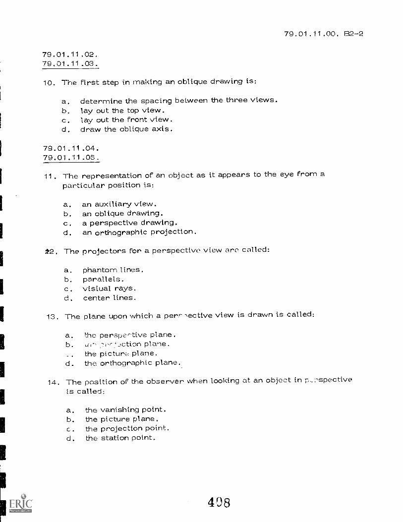
79.01.11.00. 92 -2
79.01.11.02.79.01.11.03.
10. The first step in making an oblique drawing is:
a, determine the spacing between the three views.b. lay out the top view.c. lay out the front view.d. draw the oblique axis.
79.01.11.04.79.01.11.05.
11. The representation of an object as it appears to the eye from aparticular position is:
a. an auxiliary view.b. an oblique drawing.c. a perspective drawing.d. an orthographic projection.
/2. The projectors for a perspective view are called:
a. phantom lines.b. parallels.c. visival rays.d. center lines.
13. The plane upon which a perr--,ective view is drawn is called:
a. the perspe-tive plane.b. Lr.- .-isr'2ction plane.
the picture plane.d. the orthographic plane.
14. The position of the observer when looking at an object in p_:,spectiveis called:
a. the vanishing point.b. the picture plane.c. the projection point.d. the station point.
408

79.01.11.04.79.01.11.05.
15. The first step in drawing a perspective is to:
a. d raw the top view.b. draw the visual rays.c. draw the parallels.d. draw the phantom lines.
409
79.01.11.00. B2-2
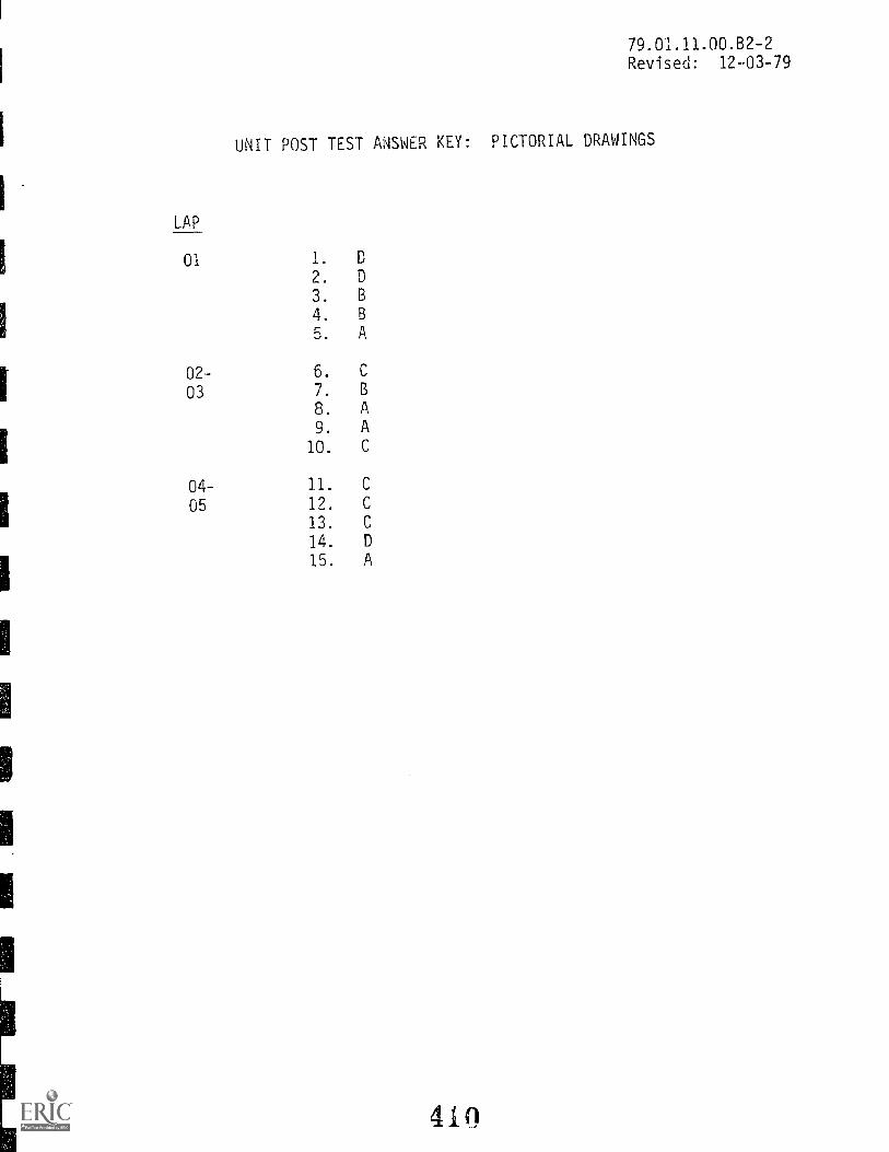
LAP
01
02-
03
04-
05
79.01.11.00.B2-2Revised: 12-03-79
UNIT POST TEST ANSWER KEY: PICTORIAL DRAWINGS
1. D
2. D
3. B
4. B
5. A
6. C
7. B
8. A
9. A
10. C
11. C
12. C
13. C
14. D
15. A
Mountain-Plains Education &Economic Development
Program. Inc.
Glasgow AFB, Montana 69231
-11
RATIONALE:
File Coda:79.01.12.00
Date Published: 1/20/78
Revised: 11/26/79
R.GoTRAET Eap@ulti@mcGi @uflEd@
COURSE: MAPPING
The use and conservation of land has become important year after year. The
importance of mapping is emphasized since it is a means to represent portions
of the earth's surface and is natural features. The purpose of this unit is
to study and use the basic systems of mapping. These systems include the plat
plan, grid work, contours, and profiles. Each drawing will be completed in the
proper manner to the proper scale. Mapping is used in many job areas. Civil
engineering, mining, construction, planning, and etc.
PREREQUISITES:
Previous units.
OBJECTIVES:
The student will demonstrate skill in the fundamentals of basic mapping: Plat
plans, contour maps, and profiles; and knowledge in their related terminology and
symbols. From a given survey plat draw a plat plan, grid squares, contours, and
a profile to scale.
RESOURCES:
Manual of Surveying Instructions; 1973 - Bureau of Land Management, Department
of Interior.Basic Technical Drawing, Spencer & Drydon, Macmillan Company, New York.
Engineering Drawing and Graphic Technology, French & Vierck, Eleventh
Edition, McGraw-Hill Book Company, New York.Mechanical Drawing, French & Svenson, Webster Division, McGraw-Hill Book
Company, New York.Technical D::awing., S_i.xth Edition, Gieseche, Mitchell, Spencer & Hill,
Macmillan Coh.prv, York.
EQUIPMENT:
Basic Drafting tools as set forth in Resource Course LEG 79.01.00.00.
Drafting Furniture: Stool, DraftingTable, Drafting (ith Tsquare, parallel rule, and/or
Drafting machine)
t:DNERAL INS'PHDC'PIONS:-
Thi:: unit cowii!;t:f of four I,ear.niin Activity Package:: (IAP's). Each !AP will
provide speeifi.e information for completion of a learning activity.
PrincipalAuthor(0: C. Wetterling, C. Lynch
411

Page 2 79.01.12.00
The general procedure for this unit is as follows:
1 Read the first assigned Learning Activity Package (LAP).
2 Begin and complete the first assigned LAP.
3. Proceed to and complete the next assigned LAP in the unit.
4. Complete all required LAP's for the unit by following steps 1 through 3.
5. Take the unit post test as described in the unit LEG "Evaluation
Procedures".6. Proceed to the next assigned unit.
PERFORMANCE ACTIVITIES:
.01 Plat Plans
.02 Grids
.03 Contours
.04 Profiles
EVALUATION PROCEDURES:
When post testing:
I. The student takes a multiple-choice post test and turns it in for correction.
2 The student takes a unit performance test. Successful unit completion is
meeting the listed criteria for the performance test.
FOLLOW-THROUGH:
Begin the first assigned Learning Activity Package (LAP) in this unit.
41 2

FmkEduca
vogran UNIT POST TEST: MAPPING
1. In
Student: File Code'
Onto.
mapping, the term "plat" refers to:
a. the science of map making.b. a chart showing a highway.c. a small map plotted from a land survey.
d. the hearing of a line.
.U1.1Z.UU
Date Published:7-27-78
Revised: 12-03-79
2. Given the following grid, what is the elevation of point C-4.
a. 18
b. 14
c. 13
d. not given
3. Using the grid, which contour map is correct?
V.)25
4. The contour
/5
ra
line is a
N0 a- ±ia
line of points which:
are in a straight horizontal line.
b. are in a str'72f. vertical line.
c. are nn a curvtl line.
d. ,re the same elevation.
to 5 3a
15ao
30
Cd)
5. Given the traverse N30° 15'E from a point which traverse below would be the same
line:
a. N59° 45'E
b. 5300 15'W
c. S30° 15'Ed. S59° 45'W
1.1eger, Nntto,,,
413

Page 279.01.12.00
6. The profile view of a map is similar to:
a. a section view of a machined object.
b. an auxiliary view of a machined object.
c. a development of a hollow object.
d. a pictoral view of an object.
7. Every contour line will:
a. touch another contour lineb. run from one end of the map to the other.
c. close on itself if extended far enough.
d. will cross another contour line.
8. Given the following two traverses, what is the direction from point C of the
third traverse:
a. N° 75Wb. S75° Ec. N60° Ed. N60° W
9. There are how many minutes in 4035'?
a. 435 minutesb. 275 minutesc. 39 minutesd. 235 minutes
10. In mapping, what does the following symbol stand for? _s_t_a__131AD
a. a reference point for measuring.
b. a field trInsit symbol.
c. a closed trays-).d. a carcor. profile.

UNIT POST TEST ANSWER KEY: MAPPING
1. C
2. B
3. A
4.
J.
6. A
I.
8.
9. B
10. A
415
79.01.12.00
Mouvitain-Plaing Education &Economic Devclaiorncnt
Pr'.grlrn.
(ilalogow A I'll. Montana 159231
===nmIcrn44
Leamhlg
PERFORMANCE ACTiVrTY. PLAT PLANS
OBJECTIVE:
File Code:79.01.12.01
Date Published:
Revised:
1/20/78
11/26/79
y PackageSuidonr
OMB:
Given locations, bearings, and distances, the student will accurately and
correctly draw a plat plan to the correct scale.
symbols, and related terminology of plat plans.
EVALUATION PROCEDURE:
Identify the purpose,
The instructor will check the plat for accuracy, neatness, and correctness.
A multiple choice unit test will be used to check the student's understanding
of purpose, symbols, and related terminology of plat plans.
RESOURCES:
Basic Drafting FurnitureBasic Drafting InstrumentsDrafting Arm or MachineTechnical Drawing, Chapter 23
Basic. Technical Drawing, Chapter 21
Manual of Surveying Instructions; 1973 Chapter 9.
PROCEDURE:
1. Read the abovL :esuurees, book(s).
2. Obtai, a 'rj:1" of: 18" x drawing paper.
3. Have the iiit:rector ai;i-;!ign ttue north on your paper.
4. Make a drowing of tin c land survey plat plan, Page ..-106 el Basic Technical
Drawing, of 1"-4001.
5. Have the ini-:true uir ':heck your drawing for accuracy.
G. When the drawing liar, been approved by the instructor, trace he completed
map on Mylar. keRoy ail lettorng and numbering. Ink the border and
title block. Use the suggested lettering size shown on page 200 of M.S.I.
7. Make a blueprint copy of the finished drawing and submit it to the in-
structor for checking.
Note: This LAP uses three skills you have already acquired -- drawinn requires
length and ::caling.
Principal Author(s): . Lynch, C. Wetterling
416

Mountain-Plains Education leEconomic Development
Program, Inr.
Glasgow AFB Montana 60231 F till 0 'f."-0 Q.-09 t. ; tcac:
PERFORMANCE ACTIVITY: Survey Grids
OBJECTIVE:
Filo Cod°79.01.12.02:A2-0
Data Published:5-4-77
Revised: 1-12-79
:V C A if,4'1
Given notes from a checker-board survey, the student will properly lay out a grid and
plot each elevation on the grid. Understand basic survey terminology. Calculate land
area by acres.
EVALUATION PROCEDURE:
The instructor will check the grid and elevations for accuracy, neatness and correctness.
RESOURCES:
Basic Drafting FurnitureBasic Drafting InstrumentsDrafting Arm or MachineTechnical Drawing, Chapter 23Basic Technical Drawing, Chapter 21 (Figure 21-1)
PROCEDURE:
1. Obtain a sheet of 18" x 24" drawing paper.2. Using a scale of 1"=200', draw a plat plan of the "Howard Tract" found on figure 21.1
in the resource book.3. Starting at the center line of State Highway No. 83, lay out horizontal grid lines
parallel to center line at 100' intervals above and below the highway until total
"Howard Tract" is covered.4. Beginning at the wc:tern most point on the Howard Tract, start laying out parallel
vertical T:-" ;',,cs at 100' ir.t,7-vals toward the East running perpendicular to the
hori-ontal grid lines. Make sure they also cover entire area.
5. Have the instructor check both the vertical and horizontal grid lines to be sure
you've done it correctly before proceeding to the ne ".t step.
6. Label the vertical grid lines with letters. Begin at the western most point and
letter it "H". Proceed east labeling each vertical grid line (I, J, K, etc.) then
west, reversing the procedure.7. Label the horizontal grid lines with numbers. Begin at the south side and proceed
north labeling each horizontal grid line (1, 2, 3, 4, etc.). HINT: Grid coordinate
"9" maintains a 60' elevation which is the elevation of the center of highway R5 #.)
8. Using the elevations given in the surveyor's notes, plot each elevation to it's
corresponding coordinate on the grid. (See attached notes)
9. Calculate the Howard Tract land area in acres north of Highway 85. Show your work
and be able to explain your method to the instructor.
10. Keep this work on your board as it will be used for the next LAP. NOTE: This is
not the only method of laying out a grid to plot points. Check with the instructor.
Princip Author(s): C. Wetterling and C. Lynch
Revised: Jere Wheatley
4 7

ige 1
C
C l0
C - 11
C --- 12
C --- l3
C --- 14
C --- 15
D 9
D 1 0
D --- 11-1 __
D -- 12
D --- 13
D --- 14
_-- 15_ _
-- 16
D 17
D --- 18
E 2
E 3
E - 4
79.01.12.02
EVEL _ _ LOC .
E
EVEL
56
L LOC. EVEL_
40
LOC. EVEL.
131q 50
54 E 56 F ---- 14 49 G 20 49
54 E F --- 15 - - - 50 G -- 21 40
50 F. 57_ F --- 16 54 G 22 38
E 60 F --- 17 54 G 23 -- 37
E 10 52 F --- 18 48 24 36
59 11 46 F --- 19 43 G 25 ------ 38
57 E --- 12 38 L F --- 20 38 26 38
43 F - 13 35 F ---._ 21__ .
___
- - - - - 33__. ..._ ..
44 E 14 36 | F --- 22 34 H
40 E --- 15 39H - 2 54
36 E --- 16 41 G H - 3 56
E -- 17 41 2 50 4 64
E - 13 39 3 55 H 5 70
60E --- 19 -- ---- 36 4 60 6 76
53 E --- 20 ------ 31 5 64 7 75
50 E --- 21 28 6 70 65
- 43 0 --- 7 65 9 60
-_ .
G. _ ----- 60 H 10 52
35 i F 2 47 O --- 9 60 11_ .
40
34 F :3 52 10 51 12 39
34 F 4 57 1113 49
34 62 12 37 14 53
30 - 6 64 G --- 13 43 15 55
F 7 60 14 52 16 65
F 60 15 52 H --- 17 66_ .
43 F - 10 50 16 rr 63
46 11 42 17 55 60
51 12 35 18 55 20 51
418

Page
LOC. EVEL. I LOC.
H --- 21 49 I ---
H --- 22 48 I ---
I H --- 23 49
IH --- 24 49 1 ---
H --- 25 45 1 ---
IH --- 26 I ---
H --- 27 ------ 38 1 I ____
H 28 ------ 29 i I ---
H --- 29 ------ 24 I ---
I
2
3
4
5
I 6
I --- 7
I 8
9
I --- 10
I --- 11
I --- 12
I --- 13
I --- 14
I --- 15
I --- 16
--- 17
I --- 18
I --- 19
57 J
5), J
66 J
75
84 J
85 J
------ 68 J ---
Ll----- 55 J ---
41. . _
40 J ---
45 J ---
------ 54 J ---
60 J
------ 69--
70 J
69 --
70 J ---
EVEL.
20 ------ 69
21 ------ 52
22 53
23 ------ F5
94 56
25 ------ 55
26 _______. 45
27 ----- 42
28 ------ 36
J
2 58
3 62
4 68
5 72
6 89
7 90
8 70
9 60
10 53
11 45
12 39
13 49
14 50
15 60
16 72
17 80
18 80
19 89
T
i
LOC. EVEL. LOC.
79.01.12.02
EVEL.
J --- 20 72 18 90
J --- 21 69 K --- 18.5 ---- 90
22 51 K --- 19 91
J --- 23 . 52.5 K 20 81
J 24 52 K 21 72
0 --- 25 5:2 22 66
J --- 26 4') K - 23 62
J --- 27 ------ 4. K --- 24 56
J --- 23 31 25 53
K --- 26 47
K
K - 2 H4 L
K 3 56 L 66
K 4 69 3 7?
K 5 72 L 4 70
K 6 90 L 5 75
K 6.33 100 L 6 90r---
K --- 6.66 .100 L --- 6.33 100
K --- 7 ------ 91 I L --- 6.66 ,--100
K --- 8 ------ 72 L --- 7 90
K 9 6071
K 10 51 9 60
K 11 46 10 50
K --- 12 39 11 39
13 42.
L --- 12
K --- 14 45 L --- 13 45
15 56 14 47
K 16 65 L --- 15 ------ 50
K 17 80 16 64
419

Page3
LOC. EVEL.1
L 17 70 -I
L 17.5 80
L --- 18 90
I L19 ------100
L --- 20 82
L --- 21 71
1
L --- 22 67 |
L --- 23 65
L 24 61
L --- 26 46
M 2 64
11 M 3 74
M --- 4 79
M --- 5
M --- 6
M --- 7 ------ 85
M 8 /
LOC.
M --- 18
M 19
M -- 20
M --- 21
M 22
M --- 23
M --- 24
M --- 25
N --- 2
N --- 3
N - 4
N --- 5
N --- 6
EVEL.
------ 79
90
80
------ 61
52
60
70
80
90
90 |
85 N 7 78|
92 N 65
M --- 9 ------ 60
M --- 10 52
M --- 10.5 40
M --- 11 35
M --- 12 25
M --- 13 37
M --- 14 ------ 46
M --- 15 46
M --- 16 60
N 9 60
H _._ 10 55 I.
1
N 10.5 ---- 40
N --- 11
N --- 12
--- 13 ------ 20
N 14 33
N --- 15 40
N -- 16 ------ 57_._1.. . . .. ._ . _ . ... .....
._-_-.i..17 65
N --- 18 75
N 19
LOC. EVEL.
79.01.12.02
LOC. EVEL.
200 21 66
N---2l 63 0 --- 22 . 63
N 22 62 0 --- 23 59
61
N 24 59 P
P 2 53
OP - 3 63
O 2 57 P --- 4 68
0 - 3 ------ 68° --- 5 78
0 4 78 P --- 6 70
0 --- 5 . 88 P --- 7 65
0 --- 6 73 P --- 8 58
0 - 7 70 P --- 9 ------ 60
8 63_
P - 10 50_
0 9 60 P --- 11 -- 34
0 - 10 55 P --- 11.5 ---- 20
0 10,5 -- -- 40 P --- 12
0 --- 11 ------ 33 P 12.5 ----_
10_
0 12 18 P --- 13 ------ 20
0 --- 12.5 ---- 10 P -- 13.5 ---- 30
0 13 10 |
P --- 14 37
0 --- 14 30 P -- 15 47
0 15 40 P -- 16 59
0 16 58 P --- 17 70
0 --- 17 69 P 18 74
O 18 ------ 75 P --- 19 75
0 10 81 P --- 20 73
0 19.5 ---- 80 P 21 65
0 --- 20 72 P --- 22 60.5
4 2 o

1
Page 479.01.12.02
LOC. EVEL. LOC. EVEL. LOC. EVEL, LOC. EVEL
P --- 23 58 8 --- 4.5 ---- 80 S --- 10 ------ 47 T --- 14 ------ 51
R 5 ------ 81 S --- 11 43 T --- 15 ------ 56
S --- 12 ------ 35 T --- 16 57
Q R --- 6 62
Q --- 2 51 R 7, 59 S --- 13 43 T --- 17 63
Q --- 3 56 L R --- 8 ------ 59 S --- 14 ------ 53 T --- 18 ------ 65
Q --- 4 66 R Q 60 S 15 55 T --- 19 64.5
Q 5 76 ,
1
10 48 s 16 59 T --- 20 66
Q --- 6 66 8 11 37 c 17 67 T --- 21 59
s
Q 7 CO I_ I
D 12 20 --S --- 18 ---- 67
0 --- 8 57 8 13 35
___
S --- 19 --7--- 66 U
S 20 66 U --- 2 56
Q 9 60 9 J4 - 50
S 21 64 U --- 3 - 62
Q --- 10 47 R 15r,)JL
Q --- 11 361
D''
16 62 S 22 65 U --- 4 80
-1
Q --- 12 20 R 17 68 U 4.66 --- 90
Q --- 13 32 R 18 71 T U --- 5 88
T --- 2 - 50 u 6 67
Q --- 14 48 R --- 19 71
R 20 67 T --- 3 60 U 7 58
Q --- 15 51
Q --- 16 61 R 21 63
P. -- 22 57
T --- 4 ------ 71 U --- 8 49
T --- 4.5 ---- 90 U 9 60
Q --- 17 6'm
Q --- 18 ---- 72___ _____ ____
T --- 4.75 --- 90 U -- 10 55
I --- 5 ---- - 88 U --- 11 50
Q --- 19 73 s
Q --- 20 70| 3 --- 2 49
T --- 6 70 u --- 12 40
T --- 7 ----- 57 u --- 13 40
u 14 49Q --- 21 63 S --- 3 ----.- 57
T --- 3 50Q --- 22 59 S -- 4 ------ 70
T --- 9 60
T 10 56
U --- 15 54
R
--- 2 47
S --- 5 89
L S --- 6 61
s 7 59
u 16 56
T --- 11 46 U 17 58
T --- 12 37 U --- 18 62
--- 3 53 s a 53
T --- 13 45 U 19 64
4 --- 4 67
_
S 9 60
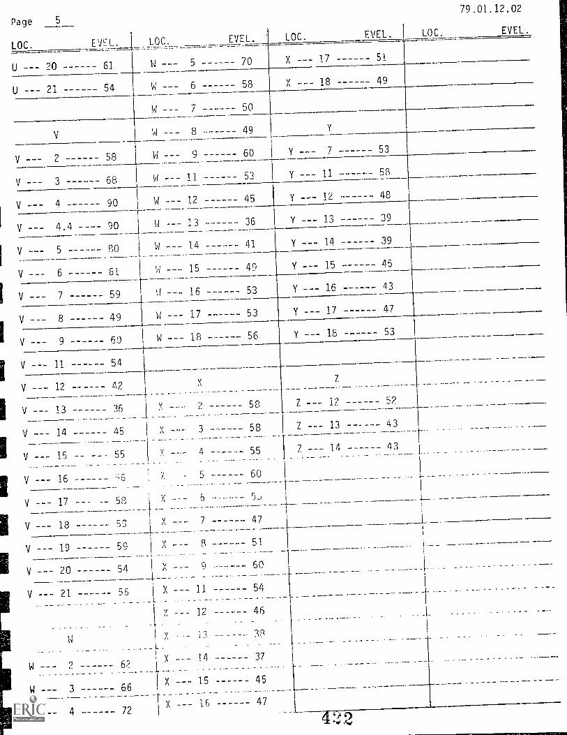
Page
LOC.
61
EVEL.
U --- 20
U 21 54
V
V --- 2 58
V --- 3 68
V --- 4 90
V --- 4.4 90
V --- 5 80
V 6 61
V 7 59
V 8 49
V 9 60
V --- 11 54
V --- 12 42
V --- 13 ------ 36
V --- 14 45
V --- 15 55
V --- 16
V --- 17 58
V --- 18 59
V- 19 59
V --- 21 56
w
W 2 62
W --- 3 66
W --- 4 72
LOC.
W
W
W ---
0
W - --
X ----
X
X ---
EVEL. t
5 70
6 58
7 50
8 49
9 60
11 53
12 45
13 36
14 41
15 49
16 53
17 53
18 56
V
2 58
3 58
4 55
60
6
7 47
8 ------ 51
11 54
12 46
13 38
14 37
15 45
1647
LOC. EVEL.
79.01.12.02
EVEL'.
X 17 51
X - -- 18 49
Y
7 - 53
Y 11 ------ 58
Y -- 12 48
Y 1.3 39
Y 14 39
Y 15 45
Y 16 ------ 43
Y 17 47
Y 18 53
7
52
43
43
7
7
7 ---
12
13
14
......
4 9')
Page
79,01.12.92
LOC. EVEL. LOC. EVEL. I LOC. EVEL. LOC. EVEL.
1
1---

Page
LOC. EVEL EVEL. LOC. EVEL. I LOC.
7P.01.12.02
EVE:.

Page
LOC. EVEL. LOC. EVEL. LOC. EVEL.
^
79.01.12.02
LOC. EVE.%

Page79.01.12.02
LOC. EVEL. LOC. EVEL. LOC. EVEL. LOC. EVEL.
I.
i
_

Page
LOC. EVEL. LOC. EVEL.
79_01.12.02
LOC. EVEL. LOC. EVEL.
-4_

EVEL. LOC. EVEL. LOC. EVEL. LOC.
79.01.12.02
EVEL.^
..... - -
Mountain-PlOnn F.dueullon1i:corms:sit. tievrIloment
(1144uow A1,11, Mmitatia 69231 Lerne 111
File Nude:79.01.12.03
Date Published. 5-4-77Revised: 5-17-78
Activity Package1:-
StUdWit
PERFORMANCE ACTIVITY: Contour Map
OBJECTIVE:
[late:
Using plotted elevations, the student will be able to properly draw a contour map
and underand it's purpose and related terminology_
EVALUATION PROCEDURE:
The instructor will check the contour map for neatness, accuracy, and correctness.
A multiple choice unit test will be used to check the student's understanding of
the map's purpose and also related-terminology.
RESOURCES:
Basic Drafting FurnitureBasic Drafting InstrumentsTechnical Drawing, Chapter 23
Basic Technical Drawing, Chapter 21
PROCEDURE:
1. Review the resources, book(s) listed above.
2. Using the survey grid blueprint made in the previous LAP, interpolate and locate
1
eaca 10 foot el-vation. NOTE: Start at the highest or lowest points where they
are cie,-'.1 e.pacid and wc,1: outward.
3. e)n the grid blueprint draw each contour line by connecting proper points.
4.
5.
Have the instructor check the drawing.
When approved by the instructor, make a completed. original of the contour map
in ink by tracing over the grid blueprint.
6. All lettering and numbering should be done using a LeRoy lettering guide.
I
7. Before reproducing the contour map, draw a heavy line from 1-29 to W-2. This
is your profile cutting plane.
I
Principal Author(s): C. Wetterling, C. Lynch, and J. Wheatley
4'ti

MountainMaims Education &Devrli.Ptnent
YrisgrArra, Inr.
(HHKaybw /11,11. M)231
PERFORMANCE ACTIVITY:
OBJECTIVE:
Given a contour map, the student will be able to draw a profile of any given location.
File Code79.01.12.04
Date Published: 5-4-77
Revised: 5-17-78
I rnhig Activity Pace,: ageStudent:
Profiles
Date:
EVALUATION PROCEDURE:
The instructor will check the profile for neatness, accuracy, and correctness. A
multiple unit test will be used to check concepts and understanding.
RESOURCES:
Basic Drafting FurnitureBasic Drafting InstrumentsTechnical Drawing, Chapter 23
Basic Technical Drawing, Chapter 21
PROCEDURE:
1. Review the above resource book(s).
2. Draw a profile showing the part of the Howard Tract which is located
along a line from coordinate 1-29 to W-2.
3. Use a scale of 1"=200' for the horizontal distances and use a scale of 1/2"=10'
fc vertic.6.]
NOTE: .!:(1,1,H the highwov is at an elevation of 59'6". The ditch
lies from Lhe of th::: highway out 70' and iLs lowest point
lies midway at an elevation of 55'.
4. The drawinq will he done in ink on a 12" x 18" sheet of Myir. Lettering will
he LeRoy.
Principal Author(s): C. Wetterling, C. Lynch, and J. Wheatley
43,0

RATIONALE:
Filo Code:79'01'13'00'31-0
Data Published.Revised:
10/7/771/25/80
rItim 11@oradafl ErzipGrA®mc® @fflOc9®
UNIT: DEVELOPMENTS AND INTERSECTIONS
Thousands of products are manufactured by cutting out the pattern and then
folding them into shape. Some examples are air-conditioning ducts, pans,
buckets, milk cartons and paper cups. In sheet metal work, development
means the laying out of a pattern. It is therefore necessary for any drafts-
man, plumber, and heating and ventilation mechanic, to be able to develop an
object on a flat surface before he can form his object or describe the object
correctly.
RERET1ISITES:
Unit: 79.01.11 Pictorial Drawings
OBJECTIVES:
Layout parallel, radial-line, intersection, and triangulation developments
given an illustration and dimensions. Form these patterns into the objects.
Identify terms and definitions for and characteristics of parallel, radial-
line, and triangulation developments.
RESOURCES:
Printed Materials
Basic Technical Drawing. Spencer & Drydon; Macmillian Company, New York.
Engineer Drawing and Graphic Technology. French & Vierck; Eleventh Edition;
McGraw-Hill Book Company, New York.
Mechanical Drawing. French & Sevenson; Webster Division, McGraw-Hill Book
Company. New York.
Technical Draw:..j. Uieseche, Mitchell, Spencer & Hill; Sixth Edition, Mac-
mil;an Company, New York.
Drafting Technology. Rotmans and Horton; Delmar Publishers.
Exploring Drafting. John Walker; Goodheart-Willcox, Illinois.
Practical Drafting for HVAC. Traister; Howard W. Sams Publishing, New York.
See Course LEG.
Equipment
Audio Visual
Video cassette on Development.
Principal Auttir;40:Jere Wheatley
bath/ Traisivice er,
Page 279.01.13.81-0
GENERAL INSTRUCTIONS:
This unit consists of four Learning Activity Packages (LAPS). Each LAP will
provide specific information for completion of a learning activity.
The general procedure for this unit is as follows:
1. Read the first assigned Learning Activity Package (LAP).
2. Begin and complete the first assigned LAP.
3. When the drawing of the layout is completed, have the instructor evaluate it.
4. Cut-out and tape the construction so that it can be checked and approved.
5. Take LAP test if indicated.
6. Proceed to and complete the next assigned LAP in the unit.
7. Complete all required LAP's for the unit by following Steps 3-5.
8. Take the unit tests as described in the Unit LEG "Evaluation Procedures".
9. Proceed to the next assigned unit.
LAP ACTIVITIES:
.01 Parallel Line Development
.02 Radial-Line Development
.03 Intersection
.04 Triangulation
EVALUATION PROCEDURE:
1. The student takes a multiple-choice post test and turns it in for correction.
2. The student takes a unit performance test. Successful unit completion is
meeting the listed Lriteria for the performance test.
FOLLOW-THROUGH:
Begin the first assigned Learning Activity Package (LAP) for this unit.
492

File Code: 79.01.13.01.A1-0
Data Publishod 1/28/80
EducationProg earni Packa e
PERFORMANCE ACTIVI1Y: Parallel Line Deve lonrriut
OBJECTIVE:
Stu&At:
Dam
Using parallel line development lay out and construct HVAC ductwork, consisting
of a square elbow, a rectangular off-set, and a rectangular-to-square transition.
EVALUATION PROCEDURE:
Instructor will examine the layout and the construction. No more than one error
per object will be allowed.
RESOURCES:
Basic Technical Drawina, pp. 341-345 (para. 17.1-17.5) and pp. 355-356 (para. 17.22)
Drafting Technology, pp. 230-237
Mechanical Drawing, pp. 291-297Exploring Drafting, pp. 150-159 (Unit 12)
Practical Drafting for HVAC, pp. 121-131 (Unit 11)
Basic Drafting Tools: (See Unit LEG)
Drafting Furniture: (See Unit LEG)
Audio visual: Video cassette on Developments
PROCEDURE:
1. Read the resource(s).
2. The HVAC illustrated 41 be.constructed in the following manner:
a. The ducting consists of three separate pieces. Each will be laid out so
that it can be cut from one piece of paper.
b. Tabs will be provided for ease of assembly.
c. The entire object will be cut out and taped together.
3. Have the instructor evaluate the duct. Take the LAP test then proceed to
LAP .02.
PrincipilAuthor(s): Jere Wheatley
433ftEaFg

Page 2
LOpen
T79.01.13.01.A/-0
4 3 d
HINT: Remember, this duct isconstructed of 3 separateparts. Each part to bea one piece pattern.
/ illy
Ed taCiatProgrm L., nrnin
File Codo 79.01.13.02.A1-0
auto Published
0 0 a a Fa- A L- " (LI Li (1:111ZatV
PERFORMANCE ACTIViTY: Radial Line Development
OBJECTIVE:
Studant:
Dato:
Using radial line development, the student will construct a funnel and a
square grain spout.
EVALUATION PROCEDURE:
Instructor will examine each layout against a prepared key. No more than one error
per object will be allowed.
RESOURCES:
Basic Technical Drawing, pg. 352 (para. 17.16)
Drafting Technology, pp. 260-261Mechanical Drawing, pg. 302 (para. 20.19)Exploring Drafting, pp. 150-154 (Unit 12)
Basic Drafting Tools: (See Unit LEG)
Drafting Furniture: (See Unit LEG)
PROCEDURE:
1. Read the above resource(s).
2. Construct the funnel illustrated on page 2.
a. Draw an or thor?raphic view of the object to full scale.
b. Use radial 'Hr.,: development as described on page 364 of Basic Technical
Drawina -3nd ,,ompict,:,. the pattern.
c. he pattern will develop as two pieces.
3. Construct the grain spout shown on page 2.
a. Draw the orthographic views needed to full scale.
b. Using radial line development, complete the pattern as described in
Basic Technical Drawing.c The pattern should be in one piece.
4. Have the instructor evaluate the completed layouts.
5. Cut out the layouts and tape them together.
6. Turn in your construction to your instructor for evaluation.
Principal Auther(s):
Jere Wheatley
Ceata, Luv.

Page 2 79. G1.13. 02. A1-0
FUNNEL
GRAIN SPOUT
Fah*Education
Fits Car 79.01.13.03.A1-0
CamPuhlistiod. 1/28/80
rograan Learnmq Ar\- ,csrd:ng [ivy t.ci2) T7 g e
PERFORMANCE ACTIVITY: 3.L.t.2.E52._cti.ng_Raof Flaogpc all Ct. bound Pipe Joints
OBJECTIVE:
Lay out and construct a round "T" stack intersecting a roof flange.
EVALUATION PROCEDURE:
Instructor will examine layout against a prepared key. No more than one error oneach part will be allowed.
RESOURCES:
Basic Technical Drawin , pp. 341-344 (para. 17.1-17.3), pg. 358 (para. 17.26)and pg. 363 Figure 17.33)
Drafting Technology, pp. 238-239 and pg. 246Exploring Drafting, pp. 150-159 (Unit 12)
Basic Drafting Tools: (See Unit LEG)Drafting furniture: (See Unit LEG)
PROCEDURE:
1. Read the above resource(s).
2. Construct the object illustrated on page 2.
a. Draw the 3 orthographic views of the object to 1" = 11-0" scale.b. Use parallel line development as described in the resources.c. The pattern be drawn as three pieces.
3. Have the completed layouts evaluated by the instructor.
4. Cut out the layout and tape them together.
5. Turn in your construction to your instructor for evaluatior.
6. Take the LAP test and proceed to LAP .04.
Principal Author(s): Jere Wheatley
rimilly (1413kr4:7'1

0
C
1-1
C
Cri
CV
C)Tsn.
V38
Scale lii:11-011
amok. riga emai AIM KO MN en an SU se
ily[ducal LI
Pr Learning iiew.:Civ y Packa
04017q" 13 A1-0File Code.
Date Published. 1/28/80
4k.; ra
PERFORMANCE ACTIVITY: Development by Tri an gul at ion
Student:
Dom
OBJECTIVE:
Lay out and construct a rectangular-to-round duct transition piece.
EVALUATION PROCEDURE:
Instructor will examine layout against a prepared key. No more than one error per
object will be allowed.
RESOURCES:
Basic Technical Drawing_, pg. 355 (para. 17.21)
Engineering Drawing and Graphic Technology, pp. 335-339
Basic Drafting Tools: (See Unit LEG)
Drafting Furniture: (See Unit LEG)
PROCEDURE:
1. Read the above resource(s).
2. Develop and lay out she transition piece shown on page 2, using the following steps.
a. Draw the 2 orthographic views to full scale.
b. Use triangulation as described in the resources.
c. Develop the pattern in one piece.
3. Have the cc7 layout eya]u ted.
4. Cut out and tape the construction together.
5. Turn in your construction to your instructor for evaluation.
6. Take the LAP test and proceed to the performance test.
Principal Author(s): Jere Wheatl ey
ily "Tudor, kw.,

Page 2 78.01.13.03.A1-0
ountain-Plain Educationonomic Development
Program, Inc.
Glasgow APB. Morilana' 59231
OBJECTIVE:
Student. File Code:79.01.13 .00 .AI-5
Dote Date Published: 10/7177
UNIT PERFORMANCE TEST: DEVELOPMENTS
The student will lay out and construct a transition piece using triangulation.
TASK:
The student will produce the transition piece illustrated for this performance
test.
ASSIGNMENT:
The student will do the following:
a. Develop the pattern in one piece.
b. Assemble the pattern to make the object conform with the check list.
CONDITIONS:
The drawing is to be completed in the drafting room, using the complete facilities.
The student will not use the instructor or other students as resources.
RESOURCES:
As listed in the LEG.
412

Page 3
42ountaln-Plairal Educe Zoo
mornIc DevelopmentProgram, Inc.
16tigegow AF13, Mraistina" 592311.1
1\ -
Student: File Code: 79. 01.13 . 00 . A1-5
Date: Date Published:10/7/77
PERFORMANCE CHECKLIST:
OVERALL PERFORMANCE: Satisfactory Unsatisfactory
CRITERIONMet Not Met
OBJECTIVE 1:
1. The entire object will be constructed and taped together
Criterion: No parts missing
. ... ,.... ____ _____ .. .OBJECTIVE 2: ...._......
2. The object is neat
Criterion: No unnecessary folds, cut edges even, object clean
OBJECTIVE 3:I--
3. All ems of th.? ,:oject join accurately
Criterion: No gaps larger than 1/32" - taping must be even
OBJECTIVE 4:
4. All dimensions of the object are to correct scale
Criterion: All measurements within 1/32"
OBJECTIVE 5:
3. 'lle proper iind correct- method will be used for the lay out.
,
Criterion: Lay out per instructions in Basic Technical
Page 4
(Checkist continued)
79.01.13.00.A1-5
CRITERIONMet Not Met
Drawing, 17.21, pg. 355
OBJECTIVE 6:
6. The drawing is completed within the specified time limit
Criterion: Not to exceed 4 hours
Student must meet criterion on 5 line items to obtain an
overall score of satisfactory.
414
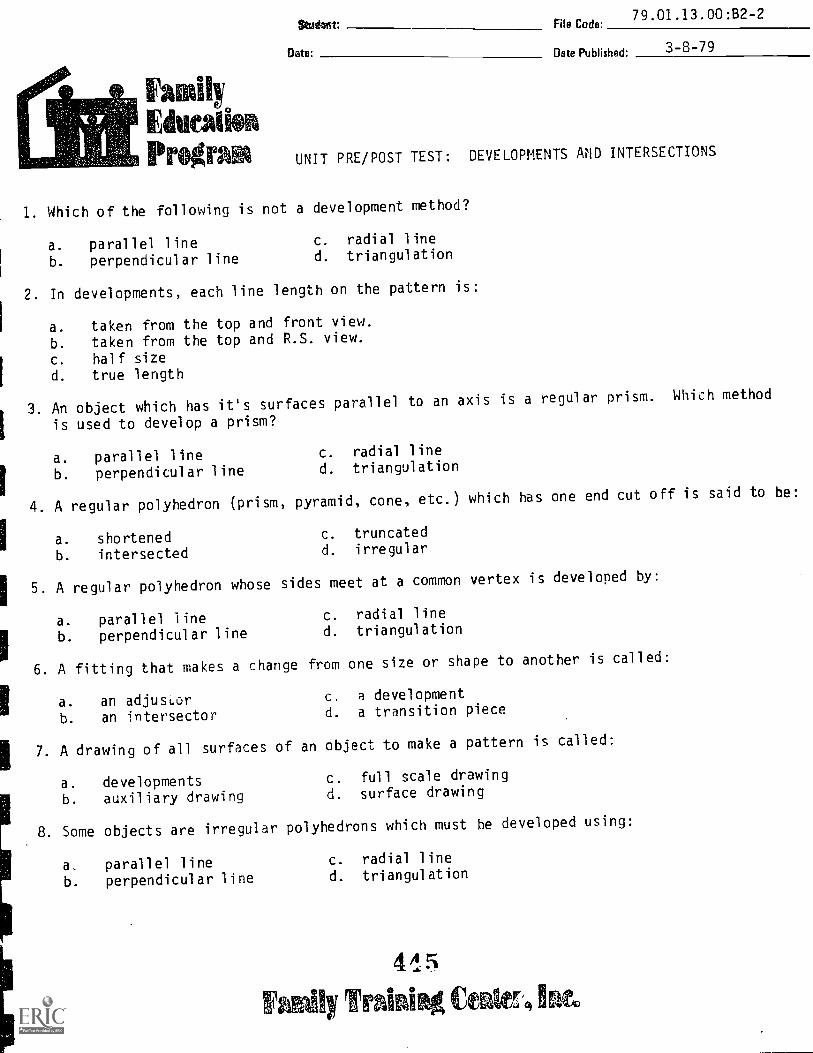
Ethical°Progra
Stsidanvt: File Code:79.01.13.00:82-2
Date. 3-8-79Date Published:
UNIT PRE/POST TEST: DEVELOPMENTS AND INTERSECTIONS
I. Which of the following is not a development method?
a. parallel line c. radial line
b. perpendicular line d. triangulation
2. In developments, each line length on the pattern is:
a. taken from the top and front view.
b. taken from the top and R.S. view.
c. half sized. true length
3. An object which has it's surfaces parallel to an axis is a regular prism. Which method
is used to develop a prism?
a. parallel line c. radial line
b. perpendicular line d. triangulation
4. A regular polyhedron (prism, pyramid, cone, etc.) which has one end cut off is said to be:
a. shortened c. truncated
b. intersected d. irregular
I5. A regular polyhedron whose sides meet at a common vertex is developed by:
a. parallel line c. radial line
b. perpendicular line d. triangulation
6. A fitting that makes a change from one size or shape to another is called:
a. an adjustor c. a development
b. an intersector d. a transition piece
7. A drawing of all surfaces of an object to make a pattern is called:
a. developments c. full scale drawing
b. auxiliary drawing d. surface drawing
8. Some objects are irregular polyhedrons which must he developed using:
a, parallel line c. radial line
b. perpendicular line d. triangulation
445
ly rffraini cenaer, inco
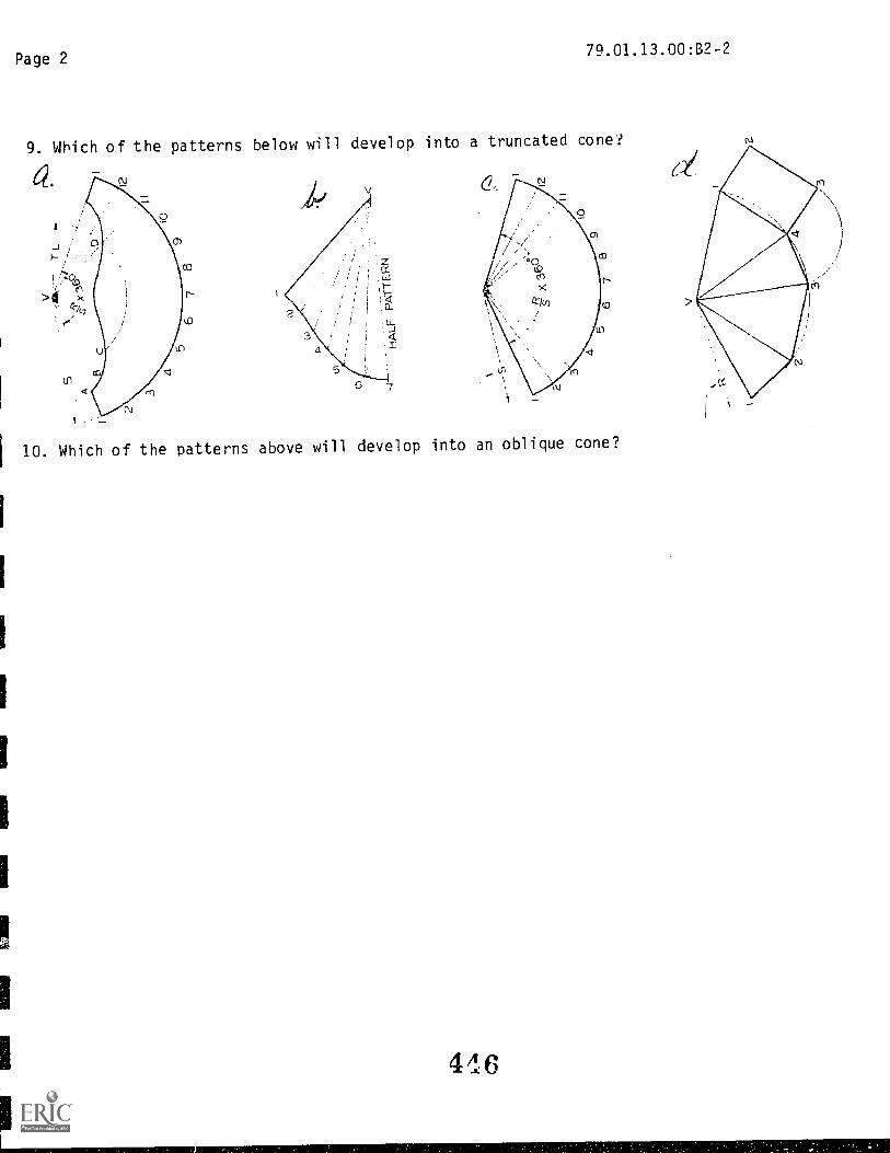
Page 279.01.13.00:B2-2
9. Which of the patterns below will develop into a truncated cone?
10. Which of the patterns above will develop into an oblique cone?
416

79.01.13.00:82-2
UNIT PRE/POST TEST ANSWER KEY: DEVELOPMENTS AND INTERSECTIONS
1. 8
2. D
3. A
4. C
5. C
6. D
7. A
8. D
9. A
10. B
Dery Onto Published: Z/21/80
FamilyEdu tiIProgr UNIT PERFORMANCE TEST: DEVELOPMENTS
OBJECTIVES:
I. The student will lay out and construct an object using parallel lines.
2. The student will lay out and construct an object using radial lines.
3. The student will lay out and construct an object using triangulation.
TASK:
The student will produce the objects illustrated for this performance test.
ASSIGNMENT:
The student will do the following:
a. Develop the pattern of each object.
b. Assemble the pattern to make the object conform with the check list.
CONDITIONS:
The drawing is to be completed in the drafting room, using the complete facilities.
The student will not use the instructor or other students as resources.
RESOURCES:
As list?.d in the LEG.
ASSIGNED TASK:
To develop the 3 assigned objects illustrated to meet the criterion on the
check list.
PROCEDURE:
Use the previous LAPs and the resources as a procedural guide.
448
Ily Train Ce ine.

4 9
N
el(7)
rts
a.
1,*-1'-/1
Radial
4-4.---01
II
Triangulation
4 0
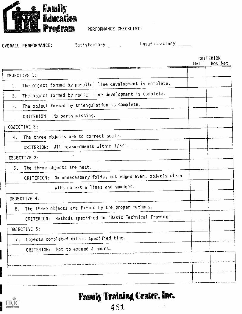
FamilyfilmProgram
OVERALL PERFORMANCE:
PERFORMANCE CHECKLIST:
Satisfactory Unsatisfactory
CRITERIONMet Not Met
OBJECTIVE 1:
I. The object formed by parallel line development is complete.
2. The object formed by radial line development is complete.
3. The object formed by triangulation is complete.
CRITERION: No parts missing.
OBJECTIVE 2:
4. The three objects are to correct scale.
CRITERION: All measurements within 1/32".......
OB6ECTIVE 3:
5. The three objects are neat.
CRITERION: No unnecessary folds, cut edges even, objects clean
with no extra lines and smudges.
OBJECTIVE 4:
6. The three objects are formed by the proper methods.
CRITERION: Methods specified in "Basic Technical Drawing"
OBJECTIVE 5:
7. Objects completed within specified time.
CRITERION: Not to exceed 4 hours.
...
Fay Trainiag Center, Inc451
File Code:79.01.14.00r
onDate Published. 11-17-78
EducatiRevised: 8-13-79
Pregr2 IlicganduDg EmpiG15@amo® @fflOci®
UNIT: WORKING DRAWINGS
RATIONALE:
It is the job of the draftsman to draw the working drawings from engineers' notes or sketches.
These working drawings must provide all the information necessary to enable the object to be
produced. This information must be presented in a standard form common to any company.
PREREQUISITES:
Unit: 79.01.13 -- Intersections and Developments
OBJECTIVES:
Prepare a set of working drawings that would enable a machinist or craftsman to make the object
Identify terms and definitions used with working drawings.
Identify purpose and characteristics of various working drawings.
RESOURCES:
Printed Materials
I Basic technical Drawing. Spencer and Drydon, Macmillan Company, New York.
I Catalog collection (Building Trades and Supplies).
Engineering Drawing and Graphic Technology. French and Vierck, Eleventh Edition, McGraw-
!Hill Book Company, New York.
Mechanical Drawing. French and Svenson, Webster Division, McGraw-Hill Book Company, New York.
Technical Drawing. Sixth Edition, Gieseche, Mitchell, Spencer and Hill, Macmillan Company,
New York.IDesign Drafting, :lames Farle, Addison-Wesley, New York.
GM Engineering Stanc:a.,.: General Motors 7.ngineering Staff.
Equipment
IBasic Drafting Tools: See Course LEG
Blue/Black line printerCutter, paper (24" or larger)
Drafting Furniture: stool, draftingtable, drafting (with T-square, parallel rule and/or drafting machine).
Primipad Authorts): S. Vosen, J. Wheatley, C. 1Ietterl ing
Family Ina' 2 Ciegar,

Page 279.01.14.00
GENERAL INSTRUCTIONS:
This unit consists of four Learning Activity Packages (LAPs). Each LAP will provide
specific information for completion of a learning activity.
The general procedure for this unit is as follows:
1) Read the first assigned Learning Activity Package (LAP).
2) Begin and complete the first assigned LAP.
3) Proceed to and complete each of the remaining LAPs in the unit.
4) Take the unit tests as described in the Unit LEG "Evaluation Procedures".
PERFORMANCE ACTIVITIES:
.01 Design Considerations
.02 Detail .Drawings
.03 Detailed Assembly Drawings
.04 Exploded View Drawings
EVALUATION PROCEDURE:
When post testing:
1. The student takes a multiple-choice post test and turns it in for correction.
2. The student takes a Unit Performance Test. Successful unit complation is
meeting the listed criteria for the Performance Test.
FOLLOW-THROUGH:
The Unit Performance Test is a set of working drawings. Copies of these may be kept
by you as examples of your work.
Begin the first assigr;e-! LAP in this unit and each LAP will be checked according to
the Performance Test criterion.

79.01.14.00(Supplement)2-20-79
DRAFTING PORTFOLIO: WORLD OF WORK
Naturally, resume's and letters of application are essential for interviews. How-
ever, in the drafting field, a portfolio of your work may be the final determination
on the decision to hire. You will need to present samples of your work showing the
different techniques and applications. Listed below are the drawings most likely
to show these. Present the one or two prints which apply most nearly to the job
to the interviewer.
Unit 05
Unit 06
Unit 11
Unit 12
Unit 14
-- 3 prints ink on vellum
-- 5 prints lead on vellum(free-hand lettering)
- - 1 print ink on mylar
- - 4 prints ink on mylar(LeRoy lettering)
-- 3-4 prints fn ink and lead on mylar
When you complete the course, you will have an original and one print of each drawing
listed. In addition, you will make a Tuf-Tex original copy of the drawings in Unit 14.
This Tur-Tex will be kept on file here at FTC.
454

Page 2 79.01.14.00(Supplement)
HOW TO BIND YOUR DRAWINGS:
1. Cut a strip of white paper (used blueprint paper works nicely) that is 21/4"
wide and as long as the left hand edge of your drawing blueprints. You will
bind this edge.
2. Fold the 1/2" edge of the strip of paper in -- towards the center.
a
FOLD LINE.
3. Fold the 1" section at the center, with k" edges folded inward.
FOLD HERE
455

Page 3 79.03.14.00(Supplement)
4. Place folded binding over even edges of left side of blueprints. Staple the
binding in several locations to secure drawings.
4

11II.untain-Plains Education &
onotnic Development
\ AFB, Mon 59281
otram. Inc.
Student' File Code: 79.01.14.00, A2-2(.01.06)
Date: Date Published- 6/21/74
UNIT/LAP PRETEST: WORKING:. DRAWINGS
1. A drawing for use in production should contain:
a. at least one auxiliary view.b. top, front, and side views always.c. as many section views as possible.d. only those, views needed for clear and complete shape description.
2. A drawing showing how all the parts fit tooeMe is called:
a. a design layout.b. a complete drawing.c. a detail drawing.d. an assembly drawing.
3. Drawings that are line-shaded, lettered in script, and protect amanufacturer are called:
a. security drawings.b. patent drawings.c. detail drawings.d. old-style drawings.
4. The number of details usually drawn on each sheet is:
a. four.b. one.c. of Five.d. as many as will fit on the sheet.
5. An assembled machine or structure is shown on:
a. an assembly drawing.b. a detail drawing.c. a staff section.d. a bill of materials.
Page 2 79.01.14.00. A2-2(.01-.06)
6. Detailed drawings and assembly drawings are included in:
a. a set of working drawings.b. a work flow diagram.c. a set of director drawings.d. all drawings made with a computer plotter.
7. On an assembly drawing, dimensions are:
a. drawn in isometric .b. always drawn.c. not drawn, as a rule.d. drawn in orthographic.
8. A working-drawing assembly is:
a. separate detail and assembly drawings.b. a combined detail and assembly drawing.c. the assembly drawing from a set of working drawings.d. the complete set of working drawings.
9. A drawing used to give a general idea of the exterior shape of a machineor structure is called:
a. an outline assembly drawing.b. a bill of materials.c. an auxiliary view.d. a detail drawing.
10. A title is drawn on:
a. every sketch and drawing.b. drawings but not sketches.c. working drawings only.d. section views.

79.01.14.00. A2-2(.01-.06)
UNIT/LAP PRETEST Ar4SWEIR KEY : WORKI1'..1G DRAWINGS
1. D2 . D3 . B4. D
5. A6. A7. C8 . B9. A
10. A
File Code:79.01.14.01
Family Dote Published:11-17-78
EducatiosProgram Learning Activity Package
PERFORMANCE ACTIVITY:Design Considerations
Student:
Oete:
OBJECTIVES:
To identify several areas of consideration when planning a working drawing. To familiarize
the student with the design process.
EVALUATION PROCEDURE:
Correctly answer at least 8 out of 10 items on a multiple choice LAP test that measures
achievement of the objective for this LAP. The instructor will review the students out-
line on the assigned problem and evaluate the results with the student.
RESOURCES:
Basic Technical Drawing -- Chapter 15Technical Drawing -- Chapter 14.Engineering Drawing and Graphic Tech. -- Chapters 14 and 23.
Design Drafting, Chapters 6 and 14.
Mechanical Drawing, Chapter 13.
PROCEDURE:
I. Read the above resource(s).2. Do a design evaluation of the lead pointer in your kit.
a. List the functions it should provide.b. List the advantages and disadvantages of the present design.
c. Make a free-hand sketch of an improvement or change in the present design.
3. Decide what information, is necessary to make a set of working drawings.
(List the work2 j drawings neeled i3A what would be placed on each).
NOTE: The above work will be done in lead on white size "A" drawing paver. Use
your best free-hand lettering style.
4. Review your work with your instructor.
5. Take the LAP test and proceed to the next LAP.
Principal Authorts): Jere Wheatley
6 0ririal.4tit tioniabr_ Mae,
FamilyEducationProgram Learning Activity Package
FileCode: 01 14-02
Oats Published:11 -17-78
Revised: 8-13-79
PERFORMANCE ACTIVITY:Detail Drawings
OBJECTIVE:
Student:
Data
Identify the characteristics and purpose of detail drawings. Prepare detail drawings.
EVALUATION PROCEDURE:
Correctly answer at least 8 out of 10 items on a multiple-choice unit test that measures
achievement of the objective for this LAP and the other LAPs for this unit.
The instructor will examine the student's drawing for completeness, line work, dimen-
sioning, lettering and accuracy using the Unit Performance Test Criterion Checklist.
RESOURCES:
Basic Technical Drawing, Chapter 14 and 15.
Mechanical Drawing, Chapter 13.Technical Drawing, Chapters 10, 13, 14 and Appendix.
Engineering Drawing and Graphic Tech., Chapters 14, 15, 23, and Appendix.
GM Standards, areas as needed.
PROCEDURE:
1. Read the above resource(s).
2. Chose an object ;Thom those shown in Chapter 15 of Basic Technical Drawing.
3. Begin a preliminary of the detail drawing(s) in pencil.
4. Neatly arrange each drawing on one or more sheets of size B or C drawing paper.
5. Completely ink and dimension the drawings on mylar.
6. Make one blueprint copy of each completed ink drawing and submit it to the in-
structor for his critique.
7. Take the LAP test and procede to the next LAP.
Principal Author(s):S. Vosen, J. Wheatley, C. Wetterling
461Traisisid fouler_ latt.

FamilyEducationProgram Learning Activity Package
Flo Code:79.01.14.03
Date Pub Inhod:11-17-78
Revised: 8-13-79
Student:
Out.:
PERFORMANCE ACTIVITY:Unit (Detail) Assembly Drawings
OBJECTIVE:
Identify the characteristics and purpose of unit (Detail) assembly drawings. Prepare
a unit assembly drawing.
EVALUATION PROCEDURE:
Correctly answer at least 8 out of 10 items on a multiple-choice unit test that measures
achievement of the objective for this LAP and the other LAPs for this unit.
The instructor will examine the student's drawing for completeness, line work, dimen-
sioning, lettering and accuracy using the Unit Performance Test Criterion Checklist.
RESOURCES:
Basic Technical Drawing -- Chapter 15.Mechanical Drawing -- Chapter 13.Technical Drawing -- Chapter 14.GM Standards as needed.ED and GT -- Chapter 23.
PROCEDURE:
1. Read the above resourcc(s).
2. Begin a nreliminary of the unit (Detail) assembly drawing(s) in pencil
3. Prepare a bill of materials.
4. Completely ink the drawing on mylar.
5. Make one blueprint copy and give it to the instructor for his critique.
6. Take LAP test and proced1 to the next LAP.
III
Principa Author(s):S. Vosen, J. Wheatley, C. Wetter lingl
maihr Traiviimiamitr.
File Code:79.01.14.04
bodily Dote Published:11-17-78
EthiCaliftRevised' 8-13-79
Program Learning Activity Package
PERFORMANCE ACTIVITY:Exploded View Drawings
Student:
Oct.:
OBJECTIVE:
Identify the characteristics and purpose of exploded view drawings. Prepare an exploded
view drawing.
EVALUATION PROCEDURE:
Correctly answer at least 8 out of 10 items on a multiple-choice unit test that measures
achievement of the objective for this LAP and the other LAPs for this unit.
The instructor will examine the student's drawing for completeness, line work, dimen-
sioning, lettering and accuracy using the Unit Performance Test Criterion Checklist.
RESOURCES:
Basic Technical Drawing -- Chapter 15.
Mechanical Drawing -- Chapter 13.
Technical Drawing -- Chapter 14.ED & GT -- Chapter 23.Design Drafting -- Chapter 18.
PROCEDURE:
1. Read the abo-e recourceks).
2. Begin a ereliminary of the exploded view drawing(s) in pencil. Use Isometric
representation.
3. Properly arrange all parts and proceed to make an ink drawing on my1ar.
4. Make one blueprint copy and give it to the instructor for his critique.
5. Take LAP test and you have it made!
Principal Authorfs): S. Vosen, J. Wheatley, C. Wetterling
Vi arallhu Irmaiivskiafiguataim 160

tt tin tan-Plans Education 4onoralc Development
oigam, Inc.
Glasgow APB. MontanF 141231-;
Student File Code- 79.01.14.00 . 132-2(.01-.06)
Date: Date Published- 6/21/74
UNIT/LAP POST TEST: WORKING DRAWINGS
1. Working drawings of individual parts are referred to as:
a. separate drawings.b. detail drawings.c. individual drawings.d. piece drawings.
2. A bill of materials is:
a. how much you c" e for the materials.b. a parts list.c. not used with working drawings.d. like any monthly bill.
3. An assembled machine or structure is shown on
a. an assembly drawing.b. a detail drawing.c. a staff section.d. a bill of materials.
4. The purpose of an assembly drawing is:
a. to describe the shape of individual parts.b. to show how parts fit together and suggest the function of the
unit.c . to snow standard details.d. to provide a bill of materials.
5. On an assembly drawing, hidden lines are:
a. left out completely.b. used as needed for clarity.c. always drawn.d. drawn as solid lines.

Page 2 79.01.14.00. B2-2(.01-.06)
6. On an assembly drawing, dimensions are:
a. drawn in isometric.b. always drawn.c. not drawn, as a rule.d. drawn in orthographic.
7. A working-drawing assembly is:
a. separate detail and assembly drawings.b. a combined detail and assembly drawing.c. the assembly drawing from a set of working drawings.d. the complete set of working drawings.
8. All necessary information not given directly on a drawing withdimensions and notes is shown in:
a. the parts list.b. the assembly drawing.c. the section view.d. the title and record strip.
9. A drawing used to give a general idea of the exterior shape of amachine or structure is called:
a. an outline assembly drawing.b. a bill of materials.c. an auxiliary view.d. a detail drawing.
10. All the r-f,-.)r^mation necessary to make something is given in:
a. a working drawing.b. an assembly drawing.c. an auxiliary drawing.d. a sectional drawing.
4e5

79.01.14.00. 82-2(.01-.06)
UNIT/LAP POST TEST ANSWER KEY: WORKING DRAWINGS
1. B2. B3. A4. B5. A
6. C7. B8. D9. A10. A
OBJECTIVE:
MOW: NW Code:79.01.14.00
Date:
LuridlyEdve,Alion
2-26-79Date Published.
Date Revised: 8-13-79
PrOgrAin UNIT PERFORMANCE TEST: WORKING DRAWING
The student should be able to make a working drawing which completely describes the
object and complete it in an assigned period of time.
TASKS:
1. Given a sketch of the object, the student will provide the required orthographic
drawing.2. Given a sketch of the object, the student will provide the required isometric drawing.
3. Given an object, the student will provide the required isometric sketch and ortho-
graphic sketches with dimensions.4. Given a representation of an object, the student will provide a Diazo print of the
required orthographic drawing.
ASSIGNMENTS:
1. See page 2.2. See page 4.3. See page 6.4. See page 6.
CONDITIONS:
The drawings will be completed in tMi. drafting area using the complete facilities.
The instructor and other students may not be used as resources.
RESOURCES:
As lisi-ed ja the Course LEG.
Famf:y Trainir* Center.
47
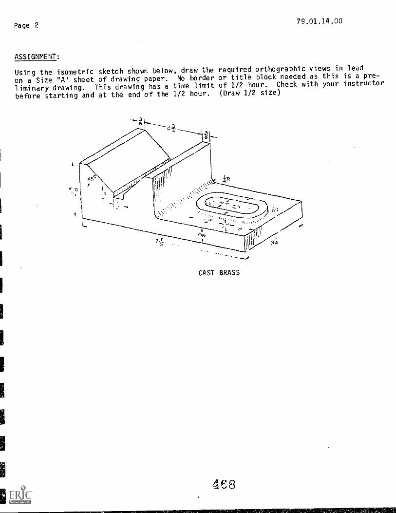
Page 279.01.14,00
ASSIGNMENT:
Using the isometric sketch shown below, draw the required orthographic views in lead
on a Size "A" sheet of drawing paper. No border or title block needed as this is a pre-
liminary drawing. This drawing has a time limit of 1/2 hour. Check with your instructor
before starting and at the end of the 1/2 hour. (Draw 1/2 size)
3;e
2i
45r
.1R
1111
76 34
CAST BRASS
4E8
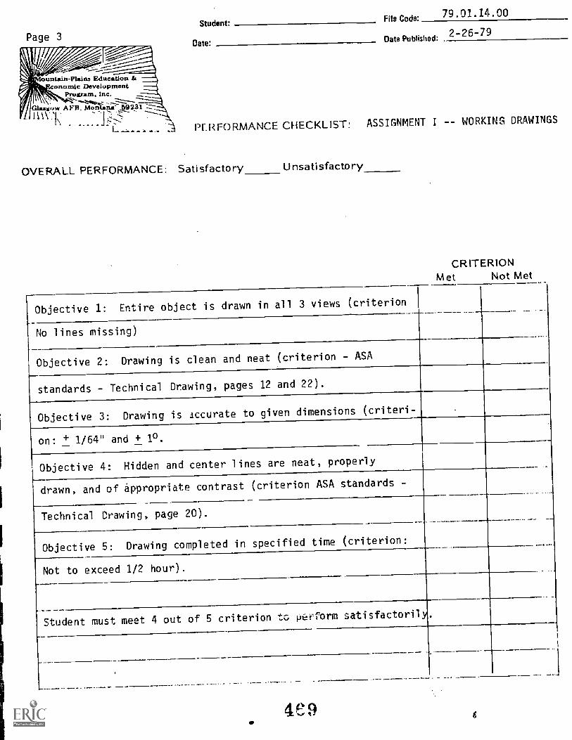
Page 3
,,ountain-Plain Education &Gnomic Development
Program, Inc.
f' Glasgow A FR. Montana-
Student:File Code: 79.01.14.00
Date:Date Published-
2-26-79
PERFORMANCE CHECKLIST: ASSIGNMENT I -- WORKING DRAWINGS
OVERALL PERFORMANCE: Satisfactory Unsatisfactory
CRITERIONMet Not Met
Objective 1: Entire object is drawn in all 3 views (criterion
No lines missing)
Objective 2: Drawing is clean and neat (criterion - ASA
standards - Technical Drawing, pages 12 and 22).
Objective 3: Drawing is accurate to given dimensions (criteri-
on: + 1/64" and + 10.
Objective 4: Hidden and center lines are neat, properly
drawn, and of appropriate contrast (criterion ASA standards -
Technical Drawing, page 20).
Objective 5: Drawing completed in specified time (criterion:
Not to exceed 1/2 hour).
.__Student must meet 4 out of 5 criterion tc, pefform satisfactorily.

Page 4
ASSIGNMENT 2:
79.01.11.00
Using the orthographic sketch shown below, draw an isometric view of the object in pencil
on a Size "A" sheet of drawing paper. No border or title block needed as this is a pre-
liminary drawing. This drawing has a time limit of 1/2 hour. Check with your instructor
before starting and at the end of the 1/2 hour.
JIG I e
Cks r lies)-
4!n

ountain-Plains Education &onornlc Development
Program. Inc.
(1Ggown A;s11;. 15tasonII\ I
Student: File Code:79.01.14.00
Date: Date Pub!isheni2-25-79
PERFORMANCE CHECKLIST: ASSIGNMENT 2: WORKING DRAWINGS
OVERALL PERFORMANCE: Satisfactory_ Unsatisfactory
CRITERIONMet Not Met
Objectives:
1. Entire object drawn. (criterion: no missing lines)
2. Proper isometric techniques used. (criterion: articles
169 and 170; Handbook of Drafting Rules)
3. Drawing is clean and neat. (criterion: ASA Standards --
Technical Drawing pages 12 and 22).
4. Drawing is accurate to given dimensions. (criterion: +
1/64" + 1°).
5. DraWng completed in specified time. (criterion: not to
exceed 1/2 hour).
Student must meet 4 out of 5 criterion to complete satisfactorily.
471

Page 679.01.14.00
ASSIGNMENT 3:
Using the object provided by the instructor, take the necessary measurements and
sketch the orthographic views with dimensions, then make an isometric sketch. The
sketches will be done in lead on a size B sheet of drawing paper. No border or title
block needed. These drawings have a time limit of one (1) hour. Check with your
instructor before starting and at the end of the hour.
ASSIGNMENT 4:
Using the caliber drawing shown below, draw the orthographic views of the object in
ink on size B vellum. Use the accepted border and title block. Make a Diaz° print.
This print has a time limit of two (2) hours. Check with your instructor before
starting and at the end of two (2) hours.
Fillets and rounds 1/2P,
ISOR /LL
NN
-- -33----6--
CAST ALUMINUM
3
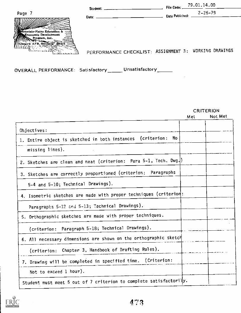
Page 7
ountain-Plains Education is07:
7
onornic DevelopmentProgram"Bic
Glasgow A FB, Mon itis-- .231\s.,*; 1
PERFORMANCE CHECKLIST: ASSIGNMENT 3 : WORKING DRAWINGS
Student: File Code'79.01.14.00
Date: Date Publi,,hed:2-26-79
OVERALL PERFORMANCE: Satisfactory Unsatisfactory
CRITERIONMet Not Met
Objectives:
1. Entire object is sketched in both instances (criterion: No
missing lines).
2. Sketches are clean and neat (criterion: Para 5-1, Tech. Dwg.)
3. Sketches are correctly proportioned (criterion: Paragraphs
5-4 and 5-10; Technical Drawings).
4. Isometric sketches are made with proper techniques (criterion:
Paragraphs 5-12 ard 5-13; Technical Drawings).
5. Orthographic sketches are made with proper techniques.
(criterion: Paragraph 5-18; Technical Drawings).
6. All necessary dimensions are shown on the orthographic sketct.
(criterion: Chapter 3, Handbook of Drafting Rules).
7. Drawing will be completed in specified time. (Criterion:
Not to exceed 1 hour).
Student must meet 5 out of 7 criterion to complete satisfactorily.
4'71tl
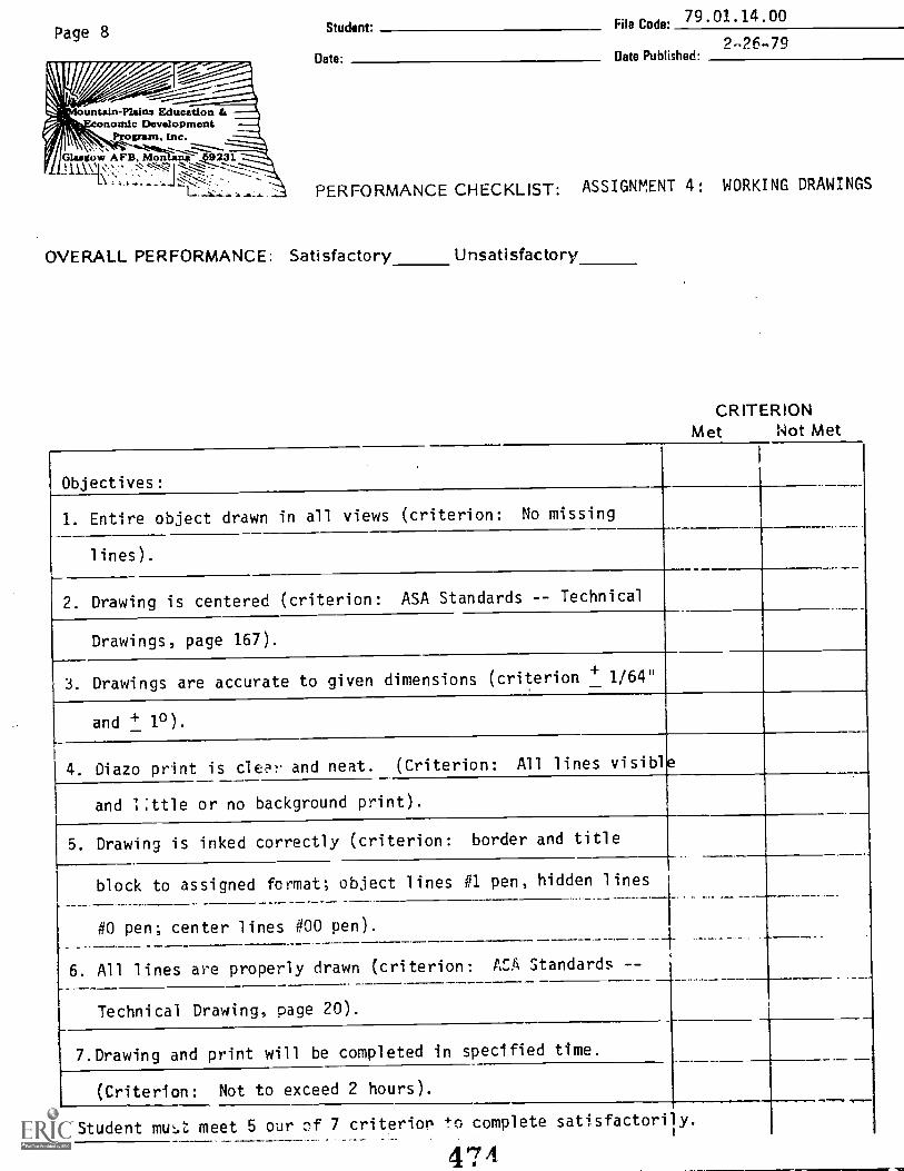
Page 8
11"IS' tuitain-Plains Education
onomic DevelopmentProgram, Inc.
Glasgow AFB, Mon nii"
II\r\r.' :L171.:
Student. Fiie Code: 79 01'14 00
226-79pate' Date Published:
PERFORMANCE CHECKLIST: ASSIGNMENT 4: WORKING DRAWINGS
OVERALL PERFORMANCE: Satisfactory Unsatisfactory
CRITERIONMet Not Met
Objectives:
1. Entire object drawn in all views (criterion: No missing
lines).
2. Drawing is centered (criterion: ASA Standards -- Technical
Drawings, page 167).
3. Drawings are accurate to given dimensions (criterion + 1/64"
and + 1°).
4. Diazo print is clear and neat. (Criterion: All lines visible
and little or no background print).
5. Drawing is inked correctly (criterion: border and title
block to assigned format; object lines #1 pen, hidden lines
#0 pen; center lines #00 pen).A
6. All lines are properly drawn (criterion: ACA Standards --
Technical Drawing, page 20).
7.Drawing and print will be completed in specified time.
(Criterion: Not to exceed 2 hours).
Student mutt. meet 5 our :)f 7 criterion to complete satisfactorily.
474