mountaingate icd series induction dryersemanuals.nordson.com/finishing/files/ais/1018438b.pdf · 4...
TRANSCRIPT

Mountaingate ICD SeriesInduction Dryers
Customer Product ManualPart 1018438B
Issued 7/03
NORDSON CORPORATION AMHERST, OHIO USA
For parts and technical support, call the Industrial CoatingSystems Customer Support Center at (800) 433-9319 or
contact your local Nordson representative.
This document is subject to change without notice.Check http://emanuals.nordson.com for the latest version.

Part 11018438B � 2003 Nordson Corporation
Contact UsNordson Corporation welcomes requests for information, comments, andinquiries about its products. General information about Nordson can befound on the Internet using the following address:http://www.nordson.com.Address all correspondence to:
Nordson CorporationAttn: Customer Service555 Jackson StreetAmherst, OH 44001
NoticeThis is a Nordson Corporation publication which is protected by copyright.Original copyright date 2002. No part of this document may bephotocopied, reproduced, or translated to another language without theprior written consent of Nordson Corporation. The information containedin this publication is subject to change without notice.
Trademarks
Mountaingate, Nordson, and the Nordson logo are registered trademarksof Nordson Corporation.
Pyrex is a registered trademark of Corning Incorporated.

Table of Contents i
Part 11018438B� 2003 Nordson Corporation
Table of Contents
Safety 1. . . . . . . . . . . . . . . . . . . . . . . . . . . . . . . . . . . . . . . . . . . . . . Qualified Personnel 1. . . . . . . . . . . . . . . . . . . . . . . . . . . . . . . . . . . . . . . Intended Use 1. . . . . . . . . . . . . . . . . . . . . . . . . . . . . . . . . . . . . . . . . . . . . Regulations and Approvals 2. . . . . . . . . . . . . . . . . . . . . . . . . . . . . . . . . Personal Safety 2. . . . . . . . . . . . . . . . . . . . . . . . . . . . . . . . . . . . . . . . . . . Fire Safety 3. . . . . . . . . . . . . . . . . . . . . . . . . . . . . . . . . . . . . . . . . . . . . . . Action in the Event of a Malfunction 3. . . . . . . . . . . . . . . . . . . . . . . . . Disposal 3. . . . . . . . . . . . . . . . . . . . . . . . . . . . . . . . . . . . . . . . . . . . . . . . .
Description 4. . . . . . . . . . . . . . . . . . . . . . . . . . . . . . . . . . . . . . . . . Features 4. . . . . . . . . . . . . . . . . . . . . . . . . . . . . . . . . . . . . . . . . . . . . . . . Components 4. . . . . . . . . . . . . . . . . . . . . . . . . . . . . . . . . . . . . . . . . . . . . Theory of Operation 6. . . . . . . . . . . . . . . . . . . . . . . . . . . . . . . . . . . . . . .
Installation 8. . . . . . . . . . . . . . . . . . . . . . . . . . . . . . . . . . . . . . . . . Inspection 8. . . . . . . . . . . . . . . . . . . . . . . . . . . . . . . . . . . . . . . . . . . . . . . . System Layout and Mounting 8. . . . . . . . . . . . . . . . . . . . . . . . . . . . . .
Controller 8. . . . . . . . . . . . . . . . . . . . . . . . . . . . . . . . . . . . . . . . . . . . . . . . . . . . Coil Tray 8. . . . . . . . . . . . . . . . . . . . . . . . . . . . . . . . . . . . . . . . . . . . . . . . . . . . Power Generator 8. . . . . . . . . . . . . . . . . . . . . . . . . . . . . . . . . . . . . . . . . . . . . Exhaust 9. . . . . . . . . . . . . . . . . . . . . . . . . . . . . . . . . . . . . . . . . . . . . . . . . . . . .
System Wiring 9. . . . . . . . . . . . . . . . . . . . . . . . . . . . . . . . . . . . . . . . . . . . Wiring Guidelines 9. . . . . . . . . . . . . . . . . . . . . . . . . . . . . . . . . . . . . . . . . . . . Conduit Guidelines 9. . . . . . . . . . . . . . . . . . . . . . . . . . . . . . . . . . . . . . . . . . . Conduit List and Interconnect Diagrams 10. . . . . . . . . . . . . . . . . . . . . . . . . Power Input 10. . . . . . . . . . . . . . . . . . . . . . . . . . . . . . . . . . . . . . . . . . . . . . . . . . Interlocks 10. . . . . . . . . . . . . . . . . . . . . . . . . . . . . . . . . . . . . . . . . . . . . . . . . . . . Motion Sensor 11. . . . . . . . . . . . . . . . . . . . . . . . . . . . . . . . . . . . . . . . . . . . . . . Temperature Sensor 11. . . . . . . . . . . . . . . . . . . . . . . . . . . . . . . . . . . . . . . . . .
Setting Operating Parameters 12. . . . . . . . . . . . . . . . . . . . . . . . Startup 12. . . . . . . . . . . . . . . . . . . . . . . . . . . . . . . . . . . . . . . . . . . . . . . . . . Changing Operating Parameters 12. . . . . . . . . . . . . . . . . . . . . . . . . . . End (Temperature) Setpoint 12. . . . . . . . . . . . . . . . . . . . . . . . . . . . . . . . Ramp% 13. . . . . . . . . . . . . . . . . . . . . . . . . . . . . . . . . . . . . . . . . . . . . . . . . . Dwell Time 13. . . . . . . . . . . . . . . . . . . . . . . . . . . . . . . . . . . . . . . . . . . . . . . Proportional Band Settings 13. . . . . . . . . . . . . . . . . . . . . . . . . . . . . . . .
Proportional Band 14. . . . . . . . . . . . . . . . . . . . . . . . . . . . . . . . . . . . . . . . . . . . Integral Time 14. . . . . . . . . . . . . . . . . . . . . . . . . . . . . . . . . . . . . . . . . . . . . . . . . Derivative 14. . . . . . . . . . . . . . . . . . . . . . . . . . . . . . . . . . . . . . . . . . . . . . . . . . .
Temperature Offset/Alarms 14. . . . . . . . . . . . . . . . . . . . . . . . . . . . . . . . . Temperature Offset 14. . . . . . . . . . . . . . . . . . . . . . . . . . . . . . . . . . . . . . . . . . . Temperature Alarms 15. . . . . . . . . . . . . . . . . . . . . . . . . . . . . . . . . . . . . . . . . .
Motion Sensor Time Delay 15. . . . . . . . . . . . . . . . . . . . . . . . . . . . . . . . .

Table of Contentsii
Part 11018438B � 2003 Nordson Corporation
Daily Operation 16. . . . . . . . . . . . . . . . . . . . . . . . . . . . . . . . . . . . . Controls 16. . . . . . . . . . . . . . . . . . . . . . . . . . . . . . . . . . . . . . . . . . . . . . . . . Startup 16. . . . . . . . . . . . . . . . . . . . . . . . . . . . . . . . . . . . . . . . . . . . . . . . . . Warning Messages 17. . . . . . . . . . . . . . . . . . . . . . . . . . . . . . . . . . . . . . . . Emergency Stop 17. . . . . . . . . . . . . . . . . . . . . . . . . . . . . . . . . . . . . . . . . . Shutdown 17. . . . . . . . . . . . . . . . . . . . . . . . . . . . . . . . . . . . . . . . . . . . . . . . Power Generator LED Test Panel Display 17. . . . . . . . . . . . . . . . . . . .
Power Generator LED Indicators 18. . . . . . . . . . . . . . . . . . . . . . . . . . . . . . . Testpoints 18. . . . . . . . . . . . . . . . . . . . . . . . . . . . . . . . . . . . . . . . . . . . . . . . . . .
Maintenance 19. . . . . . . . . . . . . . . . . . . . . . . . . . . . . . . . . . . . . . . . Monthly 19. . . . . . . . . . . . . . . . . . . . . . . . . . . . . . . . . . . . . . . . . . . . . . . . . . Quarterly 19. . . . . . . . . . . . . . . . . . . . . . . . . . . . . . . . . . . . . . . . . . . . . . . . .
Troubleshooting 20. . . . . . . . . . . . . . . . . . . . . . . . . . . . . . . . . . . .
Spare Parts 22. . . . . . . . . . . . . . . . . . . . . . . . . . . . . . . . . . . . . . . . .
Service and Parts Ordering Information 22. . . . . . . . . . . . . . . Field Service Call Procedure 22. . . . . . . . . . . . . . . . . . . . . . . . . . . . . . . Parts Ordering Information 22. . . . . . . . . . . . . . . . . . . . . . . . . . . . . . . . .
Warranty Information 23. . . . . . . . . . . . . . . . . . . . . . . . . . . . . . .
Declaration of Conformity

Mountaingate� ICD Series Induction Dryers 1
Part 11018438B� 2003 Nordson Corporation
Mountaingate� ICD Series Induction Dryers
SafetyRead and follow these safety instructions. Task- and equipment-specificwarnings, cautions, and instructions are included in equipmentdocumentation where appropriate.
Make sure all equipment documentation, including these instructions, isaccessible to persons operating or servicing equipment.
Qualified PersonnelEquipment owners are responsible for making sure that Nordson equipmentis installed, operated, and serviced by qualified personnel.
WARNING: The control panel, power generator, and coil tray contain highvoltages and high power levels that can be fatal. Allow only qualifiedpersonnel to access these enclosures.
Qualified personnel are those employees or contractors that
� have experience operating and maintaining high-power and high-voltageelectrical equipment.
� can safely perform their assigned tasks.
� are familiar with all relevant safety rules and regulations and arephysically capable of performing their assigned tasks.
Intended UseUse of Nordson equipment in ways other than those described in thedocumentation supplied with the equipment may result in injury to personsor damage to property.
Some examples of unintended use of equipment include
� using incompatible materials and atmospheres
� making unauthorized modifications
� removing or bypassing safety guards or interlocks
� using incompatible or damaged parts
� using unapproved auxiliary equipment
� operating equipment in excess of maximum ratings
Mountaingate� ICD Series Induction Dryers2
Part 11018438B � 2003 Nordson Corporation
Regulations and ApprovalsMake sure all equipment is rated and approved for the environment in whichit is used. Any approvals obtained for Nordson equipment will be voided ifinstructions for installation, operation, and service are not followed.
This equipment meets the following European Community Standards:
� EN60204 - Electrical Safety of Machinery
� EN292 - Safety Machinery
� EN55011 - Emissions of ITE Equipment
� EN50082-2 - Immunity of Heavy Industrial Equipment
These standards comprise all relevant standards for CE Approvals, and theequipment is so approved and certified.
Personal SafetyTo prevent injury follow these instructions:
� Do not operate or service equipment unless you are qualified.
� Do not operate equipment unless safety guards, doors, or covers areintact and automatic interlocks are operating properly. Do not bypass ordisarm any safety devices.
� Make sure that the ventilation system is operating properly to preventdangerous concentrations of volatile particles or vapors.
� Keep clear of moving equipment. Before adjusting or servicing movingequipment, shut off the power supply and wait until the equipmentcomes to a complete stop. Lock out power and secure the equipment toprevent unexpected movement.
� Disconnect, lock out, and tag switches before servicing electricalequipment.
� Keep parts of your body and metal implements away from the inductionheating zone while the system is energized. Metal objects will heat upvery quickly. Remove all jewelry, watches, and rings.
� Obtain and read Material Safety Data Sheets (MSDS) for all materialsused. Follow the manufacturer’s instructions for safe handling and useof materials, and use recommended personal protection devices.
� To prevent injury, be aware of less-obvious dangers in the workplacethat often cannot be completely eliminated, such as hot surfaces, sharpedges, energized electrical circuits, and moving parts that cannot beenclosed or otherwise guarded for practical reasons.

Mountaingate� ICD Series Induction Dryers 3
Part 11018438B� 2003 Nordson Corporation
Fire SafetyTo avoid a fire or explosion, follow these instructions:
� All equipment must be grounded and bonded to the building ground.
� Do not heat materials to temperatures above those recommended.Make sure heat monitoring and limiting devices are working properly.
� Provide adequate ventilation to prevent dangerous concentrations ofvolatile particles or vapors. Refer to local codes or your material MSDSfor guidance.
� Do not disconnect live electrical circuits while working with flammablematerials. Shut off power at a disconnect switch first to preventsparking.
� Know where emergency stop buttons, shutoff valves, and fireextinguishers are located.
� Clean, maintain, test, and repair equipment according to the instructionsin your equipment documentation.
� Use only replacement parts that are designed for use with originalequipment. Contact your Nordson representative for parts informationand advice.
Action in the Event of a MalfunctionIf a system or any equipment in a system malfunctions, shut off the systemimmediately and perform the following steps:
� Disconnect and lock out system electrical power.
� Identify the reason for the malfunction and correct it before restarting thesystem.
DisposalDispose of equipment and materials used in operation and servicing inaccordance with applicable laws, regulations, or codes.

Mountaingate� ICD Series Induction Dryers4
Part 11018438B � 2003 Nordson Corporation
DescriptionThe Mountaingate ICD Series Induction Dryer is designed to provide simple,efficient and uniform drying of water-based end sealing compounds. Theunit is available in single- or dual-channel models and can be configured tomate to almost any line height. ICD models are available to dry ends atspeeds up to 2200 ends per minute and diameters from 112 to 610 mm.
Features
Feature Description
Instant On/Off When the line starts, heating within the can ends instantly starts. Since heat iscreated directly within the ends, there is no thermal inertia. When the linestops, heating instantly stops. This produces a very uniform product.
No Jams The short length of the system and straight-through design minimizes jams.
Energy Savings When running, solid state induction heating is extremely efficient. Greaterthan 80% of the power consumed is directly realized as heat in the can ends.When the line stops, almost no power is consumed.
Reliability The solid-state design of the dryers minimizes downtime. There are fewmoving parts to wear out.
Small Footprint Because induction drying is so fast, the dryer is much smaller thanconventional ovens.
Temperature Control The dryer continuously monitors the temperature of the ends as they exit andadjusts power to maintain the desired setpoint, providing uniform control ofproduct quality.
Components See Figure 1.
Item Description
1 Motion Sensor—Contains an optical encoder driven by a wheel in contact with the moving stickof can ends at the entrance of the system. This sends signals to the controller when the linestarts or stops. Power is only applied when the line is moving.
2 Coil Tray—Contains the induction coil. During operation, the coil generates an alternatingmagnetic field which induces heat in the ends. The coil tray attaches to the customer infeedand outfeed system.
3 Temperature Sensor—As the can ends exit the coil tray they pass by a low-mass type Kthermocouple. The temperature of the can ends is sensed and sent to the microcontroller.Power applied to the induction coil is regulated to produce the desired can end exittemperature.

Mountaingate� ICD Series Induction Dryers 5
Part 11018438B� 2003 Nordson Corporation
Item Description
4 Power Generator—Contains the inverter that drives the induction coil. The amount of outputpower generated is varied by a time-proportional duty cycle algorithm. The microcontrollercalculates, based on the end temperature and its programmed PID parameters, a duty cyclewhich will result in the correct end temperature. The coil tray and the power generator caneither be bolted together as one unit, or can be mounted separately per customer requirement.
5 Controller—Contains the control components for the entire system, including themicrocontroller, control interface panel, fuses, circuit breakers, relays, contactors, and safetyrelated components.
The microcontroller interfaces with the operator by way of the control interface panel. Thepanel is used to set desired temperature, PID parameters, temperature alarm limits, initial startpower percentage (ramp %) and ramp % time (dwell time). The panel is simple anduser-friendly. Control keys and an LCD display screen are used to program all operatingcharacteristics.
1200004A
5
2 1
4
3
Figure 1 Typical ICD Series Dryer (Dual Channel Unit Shown)

Mountaingate� ICD Series Induction Dryers6
Part 11018438B � 2003 Nordson Corporation
Theory of OperationSee Figures 2 and 3.
The controller receives 3 phase power from the plant. The motion sensorsignals the controller when the line starts or stops to ensure that power isonly on when can ends are actively being fed into the coil tray. The coil trayreceives power from the power generator.
1200001A
Direction of Feed
Coil Tray
Controller
Incoming
Power
Power Generator
TemperatureSensor
MotionSensor
Figure 2 Theory of Operation
The can ends pass through a Pyrex tube surrounded by the coil windings.As the can ends pass through the tube, the power generator appliesalternating current to the coil windings. The coil windings generate analternating magnetic field that passes through the can ends, creating largeeddy currents. The resistance to the eddy currents generates heat, whichdries the sealing compound.

Mountaingate� ICD Series Induction Dryers 7
Part 11018438B� 2003 Nordson Corporation
1200002A
Coil
Eddy
Coil
Can
Current
Current
Windings
Ends
Figure 3 Coil Operation
A fan in the power generator directs cooling air over the electricalcomponents. The air then flows over the coil to cool it. A top- orside-mounted heater further heats the air and directs it through the coil tubeto carry off moisture vaporizing out of the end sealing compound. The airflows out of the exit end of the coil tray. If an optional magnetic separator isinstalled, heated air is also ducted directly into the separator.
The temperature sensor senses the temperature of the can ends as theyexit the coil tray and sends this data to the controller. To maintain thedesired exit temperature, the controller uses a PID loop that automaticallyadjusts the amount of power supplied to the coil from the power generator.This process eliminates temperature variations due to line voltagefluctuations, applied compound weight, can end start temperature, and linestarts and stops.
Safety interlocks include door safety interlock switches, which operateindependently of the microprocessor to shut the system down if a systemdoor is opened during operation. In addition, input and output interlocks areprovided. Interlock status is indicated on the interface panel.
Mountaingate� ICD Series Induction Dryers8
Part 11018438B � 2003 Nordson Corporation
InstallationWARNING: Allow only qualified personnel to perform the following tasks.Follow the safety instructions in this document and all other relateddocumentation.
InspectionCarefully inspect the system for obvious shipping damage and shortages. Ifany damage or shortages are noted, notify the shipper and the NordsonContainer Systems group immediately.
System Layout and Mounting Layout the system with each component in its final position on theproduction floor.
ControllerNOTE: Do not mount the controller directly on the coil tray or powergenerator.
Mount the controller within 3-3.7 m (10-12 ft) of the power generator in anarea free of vibration, dust, and high ambient temperatures, on either a wallor panel.
Optional extra length cables are available to mount the controller up to 15 m(50 ft) from the power generator and coil tray.
Coil Tray
CAUTION: Do not move the coil tray after the Pyrex tube(s) is installed.
Bolt the coil tray base to the floor through the bolt holes. Coil tray legs arefactory-made to the height listed in the purchase order. Nominal adjustmentis possible.
Power GeneratorThe power generator mounting location is dependent upon the system type.It can be mounted above, below, or to the side of the coil tray, as configuredwhen shipped. Make sure that the doors of the power generator can beopened freely.

Mountaingate� ICD Series Induction Dryers 9
Part 11018438B� 2003 Nordson Corporation
ExhaustExhaust ducting is not required, but an exhaust hood may be installed overthe exit end of the dryer. Small amounts of water vapor, hot air and in somecases solvents are released at this point.
System WiringNOTE: System wiring must conform to the National Electric Code (NEC), ifinstalled in the USA, and all applicable local codes.
Wiring Guidelines Review the following guidelines before wiring the dryer:
1. Always refer to the wiring schematics provided with the system whenmaking electrical connections.
2. The thermocouple cable is a chromel/alumel wire cable that mates withthe type K thermocouple. Do not use substitute cables. A 7.5-m (25-ft)cable is provided. Cables up to 15 m (50 ft) in length are available as anoption.
3. The motion sensor cable supplied is long enough to accommodate anymounting configuration possible. If a longer cable is needed, cables upto 50-ft (15-meters) long are available from your Nordsonrepresentative. The cable shield is grounded at the controller end onlyfor maximum noise immunity.
4. It is desirable, though not necessary, to route the motion sensor cableand the thermocouple cable through their own conduits to provideadditional noise shielding. These cables are low-level signal cables. Donot run high-power wires in the same conduits as these cables.
5. Interconnect wiring between the controller and the power generator, andthe power generator and the coil tray, are customer-supplied per thesystem schematics. Wiring length is limited. Consult Mountaingateengineering personnel.
NOTE: Wire gauges are calculated on a maximum of 15 meters betweenenclosures. Longer runs such as overhead, underground, may bepermissible but should use larger wire gauges in accordance with applicablecodes. Consult Mountaingate engineering personnel.
Conduit Guidelines Five 3/4-in. (1.9-cm) conduits are specified:
� three between the controller and power generator
� two between the power generator and the coil tray.
Larger conduit may be used if desired. Spare wires may be routed throughthe conduits if desired. You may also install small diameter conduit to shieldand protect the motion sensor and temperature sensor cables.

Mountaingate� ICD Series Induction Dryers10
Part 11018438B � 2003 Nordson Corporation
Conduit Guidelines (contd)
Ground wires are specified for each conduit. The ground wires should beconnected to specified ground points at each end. All wires should beTHHN equivalent or other agency approved nomenclature.
Install conduits and wiring as described in the conduit list and interconnectdiagrams.
NOTE: Terminations on both ends of interconnect wires are made tointerconnect terminal blocks with like-numbered wires attached.Interconnect terminal blocks are provided near conduit entry holes.
Conduit List and Interconnect Diagrams Refer to the Addendum to this manual for the conduit list and interconnectdiagrams.
Power InputLine power is supplied to the system through a 3/4-in. (1.9-cm) conduit atthe top right of the controller.
1. Route three 10 AWG (5.3 mm2) wires to the disconnect switch.
2. Route one 10 AWG (5.3 mm2) ground wire to the panel grounding stud.
InterlocksInput and output interlocks are provided for controlling and monitoringsystem operation from a remote area. Review the following guidelines:
Input Interlock
The input interlock, if activated, requires an external signal to indicate to thesystem that the shell press and liner are running. The motion sensor andthe external signal must indicate line motion before the controller will applypower.
CAUTION: It is recommended that the input interlock be connected andoperational for safety requirements. Without the interlock connection,random line motion can move the motion sensor, causing the controller tocontinue applying power when the line is stopped. The stationary endsinside the induction coil will then overheat and possibly be damaged.
1. Connect a dry contact on a relay or a 120 Vac solid state switchingmodule to wires #6 and #58 to indicate line operation. The inputinterlock is enabled by applying 120 Vac across the coil of the highvoltage contactor K13.
2. Remove the jumper installed between wires #6 and #58. This jumper isinstalled before shipping to allow immediate operation.

Mountaingate� ICD Series Induction Dryers 11
Part 11018438B� 2003 Nordson Corporation
Output Interlock
An output Interlock is provided for monitoring system status. The highvoltage contactor (K3) is activated when the start switch is pressed. A dry(NO) contact on K3 is accessible through wires #85 and #59.
The contact will open if any of the internal safety interlocks are triggered, anover- or under-temperature condition occurs, or the emergency stop or stopbuttons are pressed.
In addition, a dry contact that monitors power into the load can be supplied.Contact your Nordson representative for details.
Motion Sensor1. Mount the motion sensor bracket assembly to the matching holes at the
input side of the coil tray.
NOTE: You may install a conduit to shield and protect the motion sensor.Do not run any high-power wires through this conduit.
2. Route the cable away from any moving or hot items.
3. Make sure that the motion sensing wheel makes good contact with themoving stick of can ends.
4. Make sure that the wheel turns as the ends move.
Temperature SensorNOTE: Only one temperature sensor is provided for single and dualchannel units. An optional second sensor can be provided. The controllerwill use one sensor, depending on which line is moving, to control powerinto the coil and end heating. Contact your Nordson representative foroptions.
1. Mount the temperature sensor bracket assembly to the output side ofthe coil tray.
2. Route the cable away from any moving or hot items.
NOTE: You may install a conduit to shield and protect the temperaturesensor cable. Do not run high power wires through this conduit.
3. Make sure the temperature sensor head makes good contact with themoving stick of can ends.
Mountaingate� ICD Series Induction Dryers12
Part 11018438B � 2003 Nordson Corporation
Setting Operating ParametersWARNING: Allow only qualified personnel to perform the following tasks.Follow the safety instructions in this document and all other relateddocumentation.
Startup
1. Turn on the main power to the ICD at the controller.
2. Press and hold the white START push button for three seconds. Thecontroller will display:
MOUNTAINGATE
ICD
INDUCTION DRYER
The controller runs a self test of the Induction Dryer. If the screen displaysSELF TEST FAILED, refer to problem 3 in the troubleshooting guide. If thetest was successful, the screen will display SELF TEST PASSED.
The next screen that appears is the Main Operating - Line Stopped screen.The second line displays the actual end temperature (XX). The third linedisplays the temperature setpoint (YY).
From the Main Operating - Line Stopped screen, press the STOP button onthe controller to change any parameters.
Changing Operating Parameters Use this procedure to change operating parameters on any of the setupscreens.
1. Press the STOP button to move the underscore to the digit you areadjusting.
2. Use the up and down arrow buttons to increase or decrease the digit.Press the STOP button to accept the digit.
3. Adjust each digit as needed in the same manner. When you are done,press the ENTER button to accept the screen.
All operating parameters are stored in battery backed-up memory.
End (Temperature) Setpoint
1. From the Run or Line Stopped screen, press STOP. The Main Changescreen will appear with the asterisk next to End Setpoints. PressENTER to access the End Setpoint, Ramp Percent, and Dwell TimeChange screens.
Mountaingate� ICD Series Induction Dryers 13
Part 11018438B� 2003 Nordson Corporation
2. The End Setpoint will display on Line #1. A good starting point is65-70 �C.
NOTE: Contact the sealing compound manufacturer for recommendeddrying temperatures and temperature limits.
3. Press ENTER to accept the End Setpoint parameter. The Ramp %screen appears.
Ramp%Ramp% is the percentage of total power needed to reach the setpoint on asteady run. This value is used for a fixed period of time (Dwell Time) uponline re-starts.
Perform the following to find the optimal setting:
1. Set the Ramp % to 50%.
2. Press ENTER to accept the Ramp % parameter and display the DwellTime screen.
3. Set the Dwell Time to 900 seconds.
4. Start the dryer.
5. Check the temperature after stabilization (3 minutes).
6. If the temperature is too high, lower Ramp%; if too low, raise it.
Dwell TimeDwell time is the number of seconds it takes for an end to travel from theentrance to the exit of the Induction Dryer plus 10 seconds.
1. Measure the time that an end takes to go from the entrance to the exit ofthe coil tray (not the separator exit, if one is used), and add 10 seconds.
2. Set the Dwell Time parameter, using the time from step 1.
3. Press ENTER to accept the Dwell Time parameter. The Run or LineStopped screen appears.
Proportional Band Settings For the microcontroller to control temperature properly, three parametersmust be set:
� Proportional band (P)
� Integral (I)
� Derivative (D)
These parameters make up the PID loop that controls the duty cycle used toregulate the amount of power applied to the induction coil and ends. PIDsettings which are factory set are optimized to provide the best possibleresponse (fastest rise time with minimum overshoot).
Mountaingate� ICD Series Induction Dryers14
Part 11018438B � 2003 Nordson Corporation
Proportional Band Settings (contd)
1. From the Main Run or Line Stopped Screen, press STOP. The MainChange screen appears.
2. Press the DOWN button to move the asterisk to Line #2, PIDParameters. Press the ENTER button to access the PID screens.
NOTE: The PID parameters given below are basic starting points. Theymay be adjusted on startup by a Mountaingate service representative.
Proportional BandThe proportional band (P) is a temperature band in which partial power isapplied. Below the band, 100% of available power is used.
The proportional band should be set to 100 as the initial start point.
NOTE: Adjust the proportional band with caution. 100 is the optimalparameter for most applications.
Integral TimeThe Integral Time screen appears after accepting the Proportional Bandparameter. Integral Time (I) controls the PID integrator.
Integral Time should be set to 1900 as the initial starting point. Change thisparameter with caution (in increments of 10) in the same manner as theproportional band (P).
Note: If integral time is set too low, a large temperature overshoot will occur.The temperature may also oscillate above and below the setpoint and seemgenerally unstable. If integral time is too high, the system will be stable butsluggish and poorly regulated; it will take a long time to reach thetemperature setpoint and may wander above and below the setpoint.
DerivativeThe Derivative screen appears after accepting the Integral Time parameter.The derivative parameter (D) is used to compensate for sudden changes ininput temperature.
Since there should not be any sudden changes in end temperature, set thederivative parameter to 50. This setting should provide good performanceat any line speed.
Temperature Offset/Alarms
Temperature Offset Temperature Offset allows calibration of the temperature reading to agreewith an external calibrated temperature source. Typically, this is not usedand should be set to 0.
Mountaingate� ICD Series Induction Dryers 15
Part 11018438B� 2003 Nordson Corporation
Temperature Alarms The Temperature Alarms activate a dryer and/or line shutdown if the endtemperature deviates from the setpoint by more than the alarm amount.Normally, both under- and over-temperature alarms are set to 20 �C. Forlines with frequent stops and starts or occasional flipped ends, largerunder-and over-temperature alarms are preferable.
NOTE: The alarm is a fail-safe and should not be used to control thetemperature of the system.
If the dryer is not heating, a low temperature alarm is activated and thesystem is shut down. If the alarm band is set too tight, false shutdownssuch as those caused by frequent starts and stops will occur.
A line shutdown is activated if the alarm output is connected to the end line.The temperature alarm is NOT ACTIVE during the startup ramp, nor whenadjusting parameters.
To set the Temperature Alarms:
1. From the Main Run screen, press STOP to display the Main Changescreen.
2. Use the arrow keys to move to Temp Offset/Alarm. Press ENTER toaccept screen. The Offset screen appears.
3. Press ENTER to pass through the Offset screen. The Over Temp Alarmscreen appears. Change the over-temperature parameter as desired.Press ENTER to accept. The Under Temp Alarm screen appears.
4. Change the under-temperature parameter as desired. Press ENTER toaccept. The Main Run screen appears.
When the Temp Alarm activates, the red LED on the microcontroller and thered ALARM light on the controller will turn on. The Dryer will stop heatingends. The display will show an over- or under-temperature message.Press the START button on the controller to reset the alarm.
Motion Sensor Time DelayThe Motion Sensor Time Delay (Relay K14) signals the microprocessor topower the induction coil after a time delay. This delay ensures thatmomentary pauses or surges in line motion are not interpreted as actual linestops or starts. The time delay must be adjusted for each end line.
To set the time delay:
1. Turn on the Main Disconnect with the controller door open. Press theStart button on the controller. After the microprocessor self test, startthe end line.
2. Relay K14 has a green LED labeled V and a red LED labeled R. Thegreen V LED should be on continuously.
3. If the red R LED is flickering, or off, turn the dial on K14 clockwise untilthe red R LED remains illuminated.
4. Turn the dial counter-clockwise until the red R LED starts to flicker, thenturn the Time dial clockwise until the red R LED remains illuminated.

Mountaingate� ICD Series Induction Dryers16
Part 11018438B � 2003 Nordson Corporation
Daily OperationWARNING: Allow only qualified personnel to perform the following tasks.Follow the safety instructions in this document and all other relateddocumentation.
Controls See Figure 4.
1200005A
1
3
5
6
7
8
2
4
9
Figure 4 Controls (Typical)
1. Main disconnect2. Start button3. Stop button4. Emergency stop5. RF board
6. Mains on7. Alarm8. Run9. Microcontroller
StartupPress and hold the white START button for three seconds to turn on mainpower.
The system will heat can ends whenever the motion sensor detects movingends. When the line stops, the ICD will automatically stop heating ends. Itwill automatically resume heating when the line restarts.

Mountaingate� ICD Series Induction Dryers 17
Part 11018438B� 2003 Nordson Corporation
Warning MessagesThe system shuts down if a warning message appears on themicrocontroller screen. If the output interlock is connected, the line will alsobe shut down.
Message Description
Blower Failure Indicates a lack of air flow in the power generator or coil tray. Check theoperation of the blowers. Check for obstructed airflow through the air filters.When the problem is corrected, allow the system to cool down and restart.
Over Temp Alarm Appears when a temperature above the preset Over Temp Alarm is read. Thisalarm also can be caused by a flipped end or many quick starts and stops insuccession, depending on the status of the Motion Sensor Time Delay. Ifeither is a continual problem, enlarge the under- and over-temperature alarmband.
Under Temp Alarm Appears when a temperature below the preset Under Temp Alarm is read.This will occur if the system shuts down due to a component malfunction. Itmay also occur from many quick starts and stops in succession, depending onthe status of the Motion Sensor Time Delay. If this is a continual problem,enlarge the under- and over-temperature alarm band.
Emergency StopWhile it is possible to stop the system by either pressing the EMERGENCYSTOP button or by switching the MAIN POWER disconnect to the OFFposition, the preferred method is to use the STOP button. This results in acontrolled power down which checks all alarms and safeties and guaranteesa safe condition upon turnoff.
ShutdownPress the STOP button on the controller for at least 2 seconds. Thisinitiates a safe shutdown sequence. The Smart Shutdown Sequencescreen appears when completed.
Power Generator LED Test Panel DisplayPerformance of the power generator can be monitored from the LED TestDisplay Panel on one of the power generator doors. The Panel consists of4 amber LED indicators, 5 green LED indicators and 4 Test Points.

Mountaingate� ICD Series Induction Dryers18
Part 11018438B � 2003 Nordson Corporation
Power Generator LED Indicators
Indicator LED Color Description
OVER CURRENT Amber—Normally off Lights if excessive current is being drawn by thetank circuit. This can occur if there is a short in thepower generator or in the tank circuit.
OVER VOLTAGE Amber—Normally off Lights if the tank voltage (across the induction coil)is too high. This is typically a spike. May also becaused by incorrect input voltage. Can also light ifthe RF control board is incorrectly adjusted to theproduct load.
UNDER VOLTAGE Amber—Normally off Lights if the tank voltage (across the induction coil)is too low. The system will shut down if the tankvoltage drops more than 50%. Typically caused byinverter or drive board fault.
OUT OF PHASE LOCK Amber—Normally off Lights if the phase-lock loop fails to lock phase withthe resonant tank frequency. This occurs if the RFcontrol board is incorrectly adjusted to the productload.
PHASE A Green—Normally on Indicates that the first of two output signals from theRF control board to the inverter board is OK. Lackof signal could indicate a problem with the currenttransformer or feedback transformer.
PHASE B Green—Normally on Indicates that the second of two output signals fromthe RF control board to the inverter board is OK.Lack of signal could indicate a problem with thecurrent transformer or feedback transformer.
ENABLE Green—Pulses on/off Lights when the line movement is detected andpower is applied to the induction coil.
+15 V Green—Normally on Indicates that +15 volts DC is available for thepower generator.
-15V Green—Normally on Indicates that -15 volts is available for the powergenerator.
TestpointsUse an oscilloscope to monitor the performance of the power generator.
Testpoint Description
INVERTER CURRENT Use to monitor current to the induction coil. Should see a bipolar squarewave.
TANK VOLTAGE Use to check tank voltage. Should see a sine wave.
FREQUENCY Use to check the drive signal frequency to the inverter. Should see positivesquare wave 90� out of phase to inverter current.
COMMON Common lead connection for oscilloscope (GND).

Mountaingate� ICD Series Induction Dryers 19
Part 11018438B� 2003 Nordson Corporation
MaintenanceThe following parts of the dryer should be checked on the indicatedschedule.
WARNING: Allow only qualified personnel to perform the following tasks.Follow the safety instructions in this document and all other relateddocumentation.
Monthly
Item Procedure
Temperature Sensors Type K Thermocouple—Check for wear and good contact with ends. Replaceas needed.
Motion Sensor Make sure that the motion sensor wheel is riding directly in the center of thecan end line and rotates smoothly. If the wheel slips off the can ends, it willreport a loss of line motion and stop the system. Check the wheel for wear.
Blower Screen Inspect the blower input for dust or obstruction. If the air flow is reduced, thesystem electronics can overheat. If your system is equipped with a separator,end drying may also be affected by reduced air flow.
Coil Tray Can ends pass through the coil inside a Pyrex tube. This tube should beperiodically inspected for cleanliness and integrity. The tube can be cleanedby common solvents, but do not to get any solvent on the nylon hubs at theentry or exit of the tube. Some solvents may also have an adverse effect onthe exterior finish of the system.
If the Pyrex tube has any cracks, replace it with a tube supplied by Nordsononly. Tubes of different sizes and wall thicknesses are used depending on thecan end size and the application.
Quarterly
WARNING: Disconnect and lockout all power to the system beforeperfoming these procedures. Failure to observe may result in fatal injury topersonnel.
Item Procedure
Electrical Connections Check all wiring connections for vibration loosening in both the powergenerator and controller.
Power Generator Check for excessive dust and dirt. Vacuum if needed.

Mountaingate� ICD Series Induction Dryers20
Part 11018438B � 2003 Nordson Corporation
TroubleshootingThis section contains troubleshooting procedures. These procedures coveronly the most common problems that you may encounter. If you cannotsolve the problem with the information given here, contact your localNordson representative for help.
WARNING: Allow only qualified personnel to perform the following tasks.Follow the safety instructions in this document and all other relateddocumentation.
WARNING: The controller and power generator contain high voltageswhich can be fatal. Use extreme caution when defeating safety interlocks tocheck components at high power.
NOTE: Use the schematics provided with your system when performingtrouble shooting procedures.
Problem Possible Cause Corrective Action
1. On start uptemperaturereadings oncontroller are inerror or zerodegrees
Controller not reset at start up Press and hold Start button for aminimum of three seconds. This resetsthe controller.
2. Ends not heatingMicroprocessorLED is pulsingand screendisplays RUN
FU10,11,12 open If off, check all:
1. Connections in high power circuit.
2. Rectifier bridge (BR1).
3. IGBTs: Base to Emitter resistanceshould be > 50K ohm.
Fix & replace as needed. Replacefuses.
Loose or broken wires and terminalson interconnect wiring between powergenerator and controller
Repair & replace components asneeded.

Mountaingate� ICD Series Induction Dryers 21
Part 11018438B� 2003 Nordson Corporation
Corrective ActionPossible CauseProblem
3. Ends not heatingMicroprocessorLED is NOTpulsing and RUN
Motion sensor is not turning and/ormaking good contact with movingstick of ends
Adjust and reposition as needed.Replace if defective.
pulsing and RUNscreen does notdisplay
Motion sensor time delay relay K14out of adjustment, motion sensorcable damaged, or relay defective
Adjust relay according to procedure inSetting Operating Parameters, MotionSensor Time Delay adjustment.
Check cable between motion sensorand controller. Repair or replacedefective cable.
Replace relay K14 if necessary.
Fuses in optical isolator blocks K11and K12 defective. When both LEDson K14 are lit, LEDs on K11 and K12should light
Check fuses on K11 and K12 andreplace if defective.
4. Unit doesn’tcome on whenSTART button ispressed
E-stop is engaged Turn E-stop 1/4 turn to left to release.
pressedSmart shutdownor safety interlockmessage appears
Door safety interlocks are open Ensure all doors are closed.
5. Can ends heat,but not tosetpoint
Motion sensor time delay is set tooshort.
Adjust relay according to procedure inSetting Operating Parameters, MotionSensor Time Delay adjustment.
6. Temperaturereads nearsetpoint, but
Thermocouple does not contact ends Check thermocouple. Replace ifdefective.
setpoint, butends are over- orunder-heated
A4 needs to calibrated Calibrate A4.
7. Blower Failurewarning
Air flow is blocked Clean blower intakes.warning
Faulty blower Reset K2. Replace if defective.
8. UndertemperaturealarmTemperaturereads 0 �C(32 �F)
Faulty thermocouple Replace thermocouple.
9. Undertemperaturealarm
Line runs intermittently and alarmband is set to 10-20 �C
Widen alarm band to 30 �C.

Mountaingate� ICD Series Induction Dryers22
Part 11018438B � 2003 Nordson Corporation
Spare PartsRefer to the Addendum to this manual for spare parts.
Service and Parts Ordering Information
Field Service Call Procedure If you need a Nordson field technician to come to your plant, call Nordsonbetween the hours of 8 AM-5 PM, Monday-Friday at the following:
800-321-2870or440-988-941 1Ask for Mountaingate Service
Supply the following information:
Customer purchase order number Address of plant
Serial number and model number of unit Phone and fax number
Name of person requesting service Nature of the service call
Parts Ordering Information All parts can be ordered through Nordson Corporation. Current partspricing will be supplied at the time of order.
Nordson Customer Service7:30 AM-6 PM ESTPhone: 888-226-1697Fax: 888-229-4580Email: [email protected]
Attn Container Customer ServiceMail Station 46300 Nordson DriveAmherst, OH 44001
When ordering, have the following information available:
Customer purchase order number Required delivery date
Customer phone and fax numbers Nordson part number
Customer address Part description
Special delivery instructions Part quantity

Mountaingate� ICD Series Induction Dryers 23
Part 11018438B� 2003 Nordson Corporation
Warranty Information Nordson One Year Standard Warranty
(a) The Seller warrants that the Seller-manufactured goods, when installed, operated and maintained inaccordance with Seller’s installation, operation, and maintenance instructions, will be free of defects inworkmanship and material for a period of (a) one (1) year from initial use; (b) eighteen (18) months from dateof receipt by customer, or (c) four thousand (4000) hours of use, whichever first occurs. This warranty isvalid when the equipment is installed by authorized Mountaingate field service personnel.
Consumable and normal wear items are not covered under this warranty. Non-Warranty itemsinclude: lubrication grease and oils, hoses, tubing and fittings, belts, O-rings, gaskets, bearings,seals (rigid or inflatable) and packings, fuses and circuit breakers. In addition, powder contact parts,including but not limited to: gun nozzles, deflectors, pump throats, venturis, pick-up tubes,hopper/receiver/collector/vent utility fluidizing plates and level sensors, sieve screens, ultrasonictransducer probes and all filters and/or filter elements.
All replacement parts shall be Nordson approved. If non-approved parts are used in the system, this shallvoid the Warranty.
(b) In the event of non-compliance with the Warranty, Seller shall at its option, modify, adjust, repair orreplace the goods. Return shipping charges will be absorbed by Seller at Seller’s option.
(c) The Nordson warranty extends to all Nordson products and components integral to Nordson productsmanufactured by a third party. Components not manufactured by Nordson, but supplied through Nordson aspart of a system, shall carry the warranty of the original manufacturer.
(d) Seller assumes no responsibility for the quality or performance of coatings, adhesives or other materialsused with Seller’s goods.
(e) The above warranty does not extend to products damaged after date of shipment from Seller’s plantwhere the damage is not directly due to a defect in material or workmanship, nor does it apply to productsaltered or repaired in an unauthorized manner.
(f) The sole liability of the Seller and the exclusive remedy of the Buyer arising out of the performance ofservices or supply of the goods or their use, whether arising under contract, tort (including negligence), strictliability or otherwise shall be the modification, adjustment, repair or replacement of the goods, reperformanceof the services or refund of the purchase price.
(g) THE SELLER AND BUYER AGREE THAT, IN CONSIDERATION OF THE ABOVE EXPRESSWARRANTY AND ANY PERFORMANCE GUARANTEE SPECIFICALLY SET FORTH IN THEPROPOSAL, ALL OTHER WARRANTIES AND GUARANTEES, OTHER THAN TITLE, EITHEREXPRESSED OR IMPLIED, INCLUDING WARRANTIES OF MERCHANTABILITY AND FITNESS FOR APARTICULAR PURPOSE ARE EXCLUDED FROM THE CONTRACT.
(h) Seller shall not be held liable for costs associated with loss of production or downtime due to equipmentfailure. Seller shall not be responsible for customer, field subcontractor or trade labor costs associated withthe removal or replacement or defective or non-functioning equipment, before, during or after the Warrantyperiod.
Mountaingate� ICD Series Induction Dryers24
Part 11018438B � 2003 Nordson Corporation
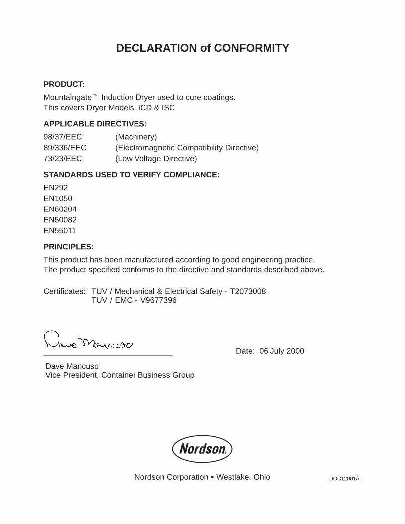
DECLARATION of CONFORMITY
PRODUCT:
Mountaingate� Induction Dryer used to cure coatings.This covers Dryer Models: ICD & ISC
APPLICABLE DIRECTIVES:
98/37/EEC (Machinery)89/336/EEC (Electromagnetic Compatibility Directive)73/23/EEC (Low Voltage Directive)
STANDARDS USED TO VERIFY COMPLIANCE:
EN292EN1050EN60204EN50082EN55011
PRINCIPLES:
This product has been manufactured according to good engineering practice.The product specified conforms to the directive and standards described above.
Certificates: TUV / Mechanical & Electrical Safety - T2073008TUV / EMC - V9677396
Date: 06 July 2000
Dave MancusoVice President, Container Business Group
Nordson Corporation � Westlake, Ohio DOC12001A