mounting and operating instructions · 3.7.3 connecting the alarm-kit hardware to the monitoring...
TRANSCRIPT

Issue 12/2018 Art. no. 7001-0379
Mounting and Operating Instructions
Alarm-Kit Art. No. 9052-0014
Alarm-Kit Hardware AlarmCenter Software
BINDER GmbH Address: Post office box 102, 78502 Tuttlingen, Germany Phone: +49 7462 2005 0 Fax: +49 7462 2005 100 Internet: http://www.binder-world.com E-mail: [email protected] Service Hotline: +49 7462 2005 555 Service Fax: +49 7462 2005 93 555 Service E-Mail: [email protected] Service Hotline USA: +1 866 885 9794 or +1 631 224 4340 x3 Service Hotline Asia Pacific: +852 390 705 04 or +852 390 705 03 Service Hotline Russia and CIS: +7 495 988 15 16

Alarm-Kit (E1) 12/2018 Page 2/28
Content
1. SAFETY .................................................................................................................. 3
1.1 Legal considerations ........................................................................................................................... 3 1.2 Structure of the safety instructions ...................................................................................................... 3
1.2.1 Signal word panel ..................................................................................................................... 3 1.2.2 Safety alert symbol ................................................................................................................... 4 1.2.3 Pictograms ................................................................................................................................ 4 1.2.4 Word message panel structure ................................................................................................. 5
2. COMPLETENESS OF DELIVERY ......................................................................... 5
3. ALARM-KIT HARDWARE ...................................................................................... 5
3.1 Technical data ..................................................................................................................................... 5 3.2 Type plate ........................................................................................................................................... 6 3.3 General safety instructions on installation and operation ................................................................... 6
3.3.1 Cleaning .................................................................................................................................... 7 3.4 Intended use ....................................................................................................................................... 7 3.5 Equipment description ........................................................................................................................ 7
3.5.1 Equipment overview ................................................................................................................. 8 3.5.2 Status LEDs .............................................................................................................................. 9 3.5.3 Alarm LEDs ............................................................................................................................... 9 3.5.4 MAC address ............................................................................................................................ 9
3.6 Storage, location of installation, and ambient conditions .................................................................. 10 3.6.1 Storage ................................................................................................................................... 10 3.6.2 Location of installation and ambient conditions ...................................................................... 10
3.7 Installation ......................................................................................................................................... 11 3.7.1 Electrical connection of the power supply unit ....................................................................... 11 3.7.2 Mounting the interchangeable input adapter .......................................................................... 11 3.7.3 Connecting the Alarm-Kit Hardware to the monitoring computer ........................................... 12 3.7.4 Connecting to an alarm facility of the customer...................................................................... 12
3.8 Notes ................................................................................................................................................. 13
4. ALARMCENTER SOFTWARE ............................................................................. 14
4.1 Installation ......................................................................................................................................... 14 4.2 Program start .................................................................................................................................... 14 4.3 Settings in the “Configuration” menu ................................................................................................ 15
4.3.1 Establishing the connection to APT-COM 4 ........................................................................... 16 4.3.2 Establishing the connection to the Alarm-Kit Hardware ......................................................... 17 4.3.3 Test alarm: Checking the connection between the Alarm-Kit hardware and the AlarmCenter19 4.3.4 E mail configuration ................................................................................................................ 20
4.4 Setting the tolerance limits in the “Chamber limits” menu ................................................................ 20 4.5 Alarm – “Alarm overview” menu ........................................................................................................ 22 4.6 Event overview with export function in the “Alarm Log View” menu ................................................. 23 4.7 Closing the AlarmCenter ................................................................................................................... 24
5. SERVICE .............................................................................................................. 25
6. DISPOSAL............................................................................................................ 26
6.1 Disposal of the transport packing ..................................................................................................... 26 6.2 Decommissioning .............................................................................................................................. 26 6.3 Disposal of the device in the Federal Republic of Germany ............................................................. 26 6.4 Disposal of the device in the member states of the EU except for the Federal Republic of Germany27 6.5 Disposal of the device in non-member states of the EU ................................................................... 28

Alarm-Kit (E1) 12/2018 Page 3/28
Dear customer,
For the correct operation of the Alarm-Kit, it is important that you read this operating manual completely and carefully and observe all instructions as indicated.
1. Safety This operating manual is part of the components of delivery. Always keep it handy for reference. The device should only be operated by laboratory personnel especially trained for this purpose and familiar with all precautionary measures required for working in a laboratory. Observe the national regulations on minimum age of laboratory personnel To avoid injuries and damage observe the safety instructions of the operating manual.
WARNING Failure to observe the safety instructions.
Serious injuries and chamber damage.
Observe the safety instructions in this operating manual
Carefully read the complete operating instructions of the chambers.
1.1 Legal considerations
This operating manual is for informational purposes only. It contains information for installing, start-up, operation and maintenance of the product. Note: the contents and the product described are subject to change without notice.
Understanding and observing the instructions in this operating manual are prerequisites for hazard-free use and safety during operation and maintenance. In no event shall BINDER be held liable for any damages, direct or incidental arising out of or related to the use of this manual.
This operating manual cannot cover all conceivable applications. If you would like additional information, or if special problems arise that are not sufficiently addressed in this manual, please ask your dealer or contact us directly by phone at the number located on page one of this manual
Furthermore, we emphasize that the contents of this operating manual are not part of an earlier or existing agreement, description, or legal relationship, nor do they modify such a relationship. All obligations on the part of BINDER derive from the respective purchase contract, which also contains the entire and exclusively valid statement of warranty administration. The statements in this manual neither augment nor restrict the contractual warranty provisions.
1.2 Structure of the safety instructions
In this operating manual, the following safety definitions and symbols indicate dangerous situations following the harmonization of ISO 3864-2 and ANSI Z535.6.
1.2.1 Signal word panel
Depending on the probability of serious consequences, potential dangers are identified with a signal word, the corresponding safety color, and if appropriate, the safety alert symbol.
DANGER
Indicates an imminently hazardous situation that, if not avoided, will result in death or serious (irreversible) injury.

Alarm-Kit (E1) 12/2018 Page 4/28
WARNING
Indicates a potentially hazardous situation which, if not avoided, could result in death or serious (irreversible) injury
CAUTION
Indicates a potentially hazardous situation which, if not avoided, may result in moderate or minor (reversible) injury
CAUTION Indicates a potentially hazardous situation which, if not avoided, may result in damage to the product and/or its functions or of a property in its proximity.
1.2.2 Safety alert symbol
Use of the safety alert symbol indicates a risk of injury.
Observe all measures that are marked with the safety alert symbol in order to avoid death or injury.
1.2.3 Pictograms
Warning signs
Electrical hazard
Explosive atmosphere
Pollution Hazard
Harmful substances
Biohazard
Mandatory action signs
Mandatory regulation
Read operating
instructions
Disconnect the power
plug
Environment protection
Prohibition signs
Do NOT touch
Do NOT spray with
water
Information to be observed in order to ensure optimum function of the product.

Alarm-Kit (E1) 12/2018 Page 5/28
1.2.4 Word message panel structure
Type / cause of hazard.
Possible consequences.
∅ Instruction how to avoid the hazard: prohibition.
Instruction how to avoid the hazard: mandatory action.
Observe all other notes and information not necessarily emphasized in the same way, in order to avoid disruptions that could result in direct or indirect injury or property damage.
2. Completeness of delivery After unpacking, please check the equipment based on the delivery receipt for completeness and for transportation damage. Inform the carrier immediately if transportation damage has occurred.
Scope of delivery:
• Alarm-Kit Hardware: Web-IO Digital 4.0, 2xIn / 2xOut with switching relay, completely wired mounted on DIN rail
• Wall mount power supply 24V/18W international, with interchangeable Euro, US, and UK input adapters
• 1m Patch cable CAT 5 Patch RJ45, (network connection)
• Alarm-Kit operating instructions, Art. no. 7001-0379
For disposal of the transport packing, see chap. 6.1.
3. Alarm-Kit Hardware
3.1 Technical data
Input voltage of the power supply (primary) 100 V up to 240 V AC at 50/60 Hz
Output voltage of the power supply 24 V DC ±5 %
Protection class of the power supply IP 40
Power supply of the IO module 12 V up to 48 V DC
Protection class of the IO module IP 20
Power consumption 0.02 kW
Zero-voltage relay / floating switch contact Maximum switching capacity DC: 192 W / 24 V
Installation height max. 2000 m / 6562 ft. above sea level
Outer dimensions (W x H x D) 235 mm x 115 mm x 255 mm
9.25 in x 4.53 in x 10.04 in

Alarm-Kit (E1) 12/2018 Page 6/28
3.2 Type plate
Figure 1: Type plate on Alarm-Kit Hardware
Indications and symbols Information BINDER Im Mittleren Ösch 5 78532 Tuttlingen / Germany www.binder-world.com
Manufacturer BINDER GmbH including address and website information
Alarm-Kit Hardware Model designation 9052-0014 Article no. of the device Built 2018 Year of construction of the device IP protection 20 IP type of protection acc. to standard EN 60529
CE conformity marking
Electrical and electronic equipment manufactured / placed on the market in the EU after 13 August 2005 and to be disposed of in a separate collection according to Directive 2012/19/EU on waste electrical and electronic equipment (WEEE).
3.3 General safety instructions on installation and operation
With regard to operating the Alarm-Kit Hardware and to the installation location, please observe the DGUV guidelines 213-850 on safe working in laboratories (formerly BGI/GUV-I 850-0, BGR/GUV-R 120 or ZH 1/119, issued by the employers’ liability insurance association) (for Germany).
BINDER GmbH is only responsible for the safety features of the equipment provided skilled electricians or qualified personnel authorized by BINDER perform all maintenance and repair, and if components relating to equipment safety are replaced in the event of failure with original spare parts.
CAUTION Danger of overheating.
Damage to the equipment.
Do NOT install the equipment in unventilated recesses.
Ensure sufficient ventilation for dispersal of the heat.
Do not operate the chambers in hazardous locations.
DANGER Explosion hazard.
Danger of death.
∅ Do NOT operate the equipment in potentially explosive areas.
KEEP explosive dust or air-solvent mixtures AWAY from the equipment.
Im Mittleren Ösch 5 / 78532 Tuttlingen / Germany www.binder-world.com
9052-0014 Alarm-Kit Hardware Built 2018 IP protection 20

Alarm-Kit (E1) 12/2018 Page 7/28
DANGER Electrical hazard.
Danger of death.
∅ The equipment must NOT become wet during operation or maintenance.
The equipment is produced in accordance with VDE regulations and is routinely tested.
3.3.1 Cleaning
DANGER Electrical hazard.
Danger of death.
∅ Do NOT spill water or cleaning agents over the inner and outer surfaces.
Disconnect the equipment before cleaning. Disconnect the power plug.
Completely dry the equipment before turning it on again.
Disconnect the equipment from the power supply before cleaning. Disconnect the power plug!
Wipe the surfaces with a moistened towel.
3.4 Intended use
The Alarm-Kit Hardware serves to transmit alarm messages released by the monitoring software AlarmCenter from BINDER, to an already existing alarm facility of the customer.
Observing the instructions in this operating manual is part of the intended use
The equipment is not classified as a medical device as defined by the Medical Device Directive 93/42/EEC.
3.5 Equipment description
The Alarm-Kit Hardware serves to transmit alarm messages released by the monitoring software AlarmCenter from BINDER, to an already existing alarm facility of the customer.
The device is equipped with an Ethernet interface for connection to the monitoring software AlarmCenter from BINDER.

Alarm-Kit (E1) 12/2018 Page 8/28
3.5.1 Equipment overview
(22)
(21)
(24)
(1) (2)
(3) (4) (5) (6)
Figure 2: Alarm-Kit Hardware
(1) Ethernet connection RJ45 (chap. 3.7.3)
(2) BINDER type plate (not shown) (chap. 3.2)
(3) Status LEDs (chap. 3.5.2)
(4) Alarm LEDs (chap. 3.5.3)
(5) Sticker indicating the MAC address (chap. 3.5.4)
(6) Connection to power supply unit (chap. 3.7.1, 3.7.2)
(22), (21), (24) Terminal clamps of the floating switch contacts (chap. 3.7.4)

Alarm-Kit (E1) 12/2018 Page 9/28
3.5.2 Status LEDs
After applying the supply voltage (plugging in the power supply), all three LEDs light up briefly (approx. 5 seconds).
• Status LED (green): flashes (normal state)
• Power LED (green): lights permanently (normal state)
• Error LED (red): lights up in case of a defect in the unit.
Figure 3: Alarm-Kit Hardware, Alarm LEDs and Status LEDs
3.5.3 Alarm LEDs
Normal state:
Alarm state:
3.5.4 MAC address
Figure 4:
Sticker indicating the MAC address (sample picture)

Alarm-Kit (E1) 12/2018 Page 10/28
3.6 Storage, location of installation, and ambient conditions
3.6.1 Storage
Intermediate storage of the equipment is possible in a closed and dry room.
Observe the guidelines for temporary decommissioning (chap. 6.2).
• Permissible ambient temperature range during storage: -10 °C to +70 °C / 14 °F to 158 °F.
• Permissible ambient humidity during storage: max. 80 % r.h., non-condensing
When after storage in a cold location you transfer the equipment to its warmer installation site, condensation may form. Before start-up, wait at least one hour until the equipment has attained ambient temperature and is completely dry.
3.6.2 Location of installation and ambient conditions
Select a convenient place for the Alarm-Kit Hardware. Set up the equipment in a well-ventilated, dry location on an even surface, free from vibration.
Installation height: max. 2000 m / 6562 ft. above sea level
Ventilation openings must be clear of any obstacles. A distance of 10-15 cm / 3.9 to 5.9 inches between the Web-IO and nearby heat sources must be maintained.
CAUTION Danger of overheating.
Damage to the equipment.
Do NOT set up the equipment in non-ventilated recesses.
Ensure sufficient ventilation for dispersal of the heat.
• Permissible ambient temperature range during operation:
• Alarm-Kit Hardware 0 °C up to +60 °C / 32 °F to 140 °F.
• Power supply unit 0 °C up to +40 °C / 32 °F to 104 °F.
• Permissible ambient humidity during operation: 80 % r.h. max., non-condensing
Note that unauthorized persons may switch off the device. We recommend installation e.g., inside a distribution box or control cabinet.
To completely separate the equipment from the power supply, you must disconnect the power plug. Install the equipment in a way that the power plug is easily accessible and can be easily pulled in case of danger
Do not install or operate the equipment in potentially explosive areas.
DANGER Explosion hazard.
Danger of death.
∅ Do NOT install the equipment in potentially explosive areas.
KEEP explosive dust or air-solvent mixtures AWAY from the vicinity of the equipment.
Alarm-Kit (E1) 12/2018 Page 11/28
3.7 Installation
Establish all connections of the Alarm-Kit Hardware prior to commissioning.
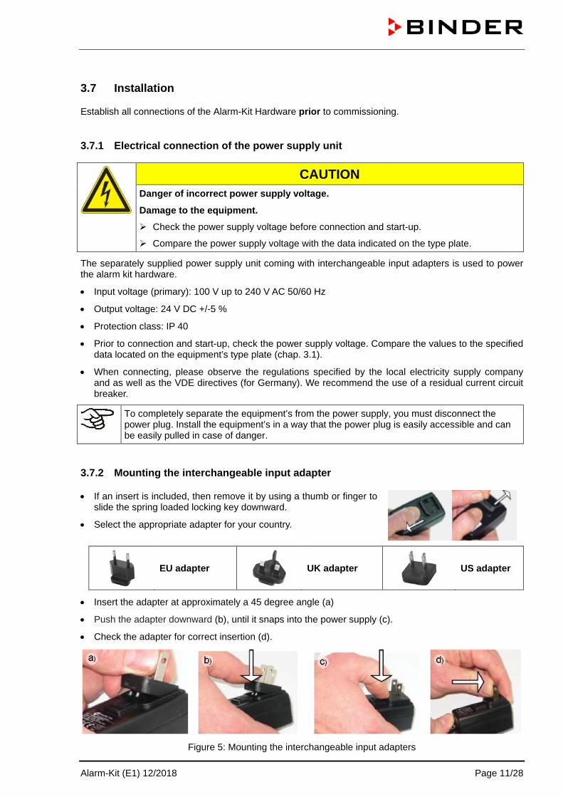
3.7.1 Electrical connection of the power supply unit
CAUTION Danger of incorrect power supply voltage.
Damage to the equipment.
Check the power supply voltage before connection and start-up.
Compare the power supply voltage with the data indicated on the type plate.
The separately supplied power supply unit coming with interchangeable input adapters is used to power the alarm kit hardware.
• Input voltage (primary): 100 V up to 240 V AC 50/60 Hz
• Output voltage: 24 V DC +/-5 %
• Protection class: IP 40
• Prior to connection and start-up, check the power supply voltage. Compare the values to the specified data located on the equipment’s type plate (chap. 3.1).
• When connecting, please observe the regulations specified by the local electricity supply company and as well as the VDE directives (for Germany). We recommend the use of a residual current circuit breaker.
To completely separate the equipment’s from the power supply, you must disconnect the power plug. Install the equipment’s in a way that the power plug is easily accessible and can be easily pulled in case of danger.
3.7.2 Mounting the interchangeable input adapter
• If an insert is included, then remove it by using a thumb or finger to slide the spring loaded locking key downward.
• Select the appropriate adapter for your country.
EU adapter
UK adapter
US adapter
• Insert the adapter at approximately a 45 degree angle (a)
• Push the adapter downward (b), until it snaps into the power supply (c).
• Check the adapter for correct insertion (d).
Figure 5: Mounting the interchangeable input adapters

Alarm-Kit (E1) 12/2018 Page 12/28
We recommend taking the electric power from a central alarm facility (as far as existing) with a backed-up power feeding (e.g. battery buffer for PCs). Only then the alarm transmission during a power failure is guaranteed.
DANGER Danger of death.
∅ Never insert an interchangeable input adapter into the socket separated from the power supply. There is a risk of electric shock.
Always use the adapter only in conjunction with the power supply unit.
3.7.3 Connecting the Alarm-Kit Hardware to the monitoring computer
The Alarm-Kit Hardware is supplied ready-to-install. It is mounted on a DIN rail (35 mm x 7,5 mm / 1.37 in x 0.3 in).
The Alarm-Kit Hardware is connected to the monitoring computer on which the monitoring software Software AlarmCenter is operated. Connection is established erfolgt via the supplied Patch cable, either directly to the monitoring computer, or through an Ethernet socket. You can also use a longer shielded network cable instead of the supplied 1m Patch cable.
Connection is established in the AlarmCenter software (chap. 4.3.2). The MAC address is indicated on a sticker on the Alarm-Kit Hardware. the IP address will be assigned by the customer’s DHCP server.
3.7.4 Connecting to an alarm facility of the customer
The zero-voltage switching contact allows transmitting an alarm to an alarm device of the customer or a central monitoring facility.
22 21
24
ALARM Pin 21: Pole
Pin 22: Break relay
Pin 24: Make contact In case there is no alarm, contact 21 closes with contact 24.
Closing contact 21 with contact 22 switches the zero-voltage relay alarm output
Connection:
Figure 6: Connecting the zero-voltage switching contacts
21
22
24

Alarm-Kit (E1) 12/2018 Page 13/28
Loading capacity of the switching contacts:
CAUTION Damage to switching contacts and connection socket.
∅ Maximum loading capacity DC: 192 W / 24 V
∅ Do NOT connect any devices with a higher loading capacity.
3.8 Notes

Alarm-Kit (E1) 12/2018 Page 14/28
4. AlarmCenter software AlarmCenter is a monitoring software that allows monitoring running measurements independent of APT-COM™ 4. It has no control over the recording computer running APT-COM™ 4 or over the chambers connected to it.
• Monitoring the communication between APT-COM / chamber controller and the AlarmCenter
The actual value controller signal, which is received via APT-COM, is continuously monitored. If communication with the controller is interrupted, an alarm will be triggered after 3 minutes. This also applies to an interruption due to power failure
Note: In the event of a power failure, the zero-voltage relay alarm contacts of the Alarm-Kit hardware are switched directly. Obtaining an alert by the AlarmCenter software during the power failure, e.g. by e-mailing, requires the computer running the AlarmCenter software to be connected to an uninterruptible power supply (UPS).
• Monitoring the individual tolerance ranges for each available parameter
The desired upper and lower limits for the parameters available depending on the chamber type are entered directly in the AlarmCenter software for each chamber (chap. 4.4).
4.1 Installation
You can find the AlarmCenter software in your APT-COM™ 4 installation folder. It is located in the “Tools” directory in the "AlarmCenter" subdirectory. You can create a shortcut on your desktop or in any directory.
4.2 Program start
Select file “AlarmCenter.exe”. The program window opens.
Alarm-Kit (E1) 12/2018 Page 15/28
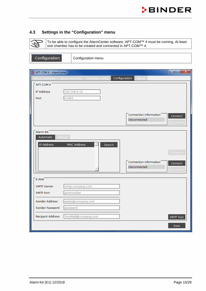
4.3 Settings in the “Configuration” menu
To be able to configure the AlarmCenter software, APT-COM™ 4 must be running. At least one chamber has to be created and connected in APT-COM™ 4.
Configuration menu

Alarm-Kit (E1) 12/2018 Page 16/28
4.3.1 Establishing the connection to APT-COM 4
After starting both APT-COM™ 4 (see APT-COM™ 4 operating manual) and the AlarmCenter, you can establish the connection between the AlarmCenter and APT-COM™ 4.
• “IP Address”: Enter the IP address of the computer on which APT-COM 4 is running.
Note: If APT-COM 4 and AlarmCenter are running on the same computer, you can also enter the local host address “127.0.0.1” as IP address.
• “Port”: The Port is preconfigured to 43345. Do not change this setting.
Select the “Save” button to adopt the settings.

Alarm-Kit (E1) 12/2018 Page 17/28
4.3.2 Establishing the connection to the Alarm-Kit Hardware
Once the connection between AlarmCenter and APT-COM™ 4 has been established (chap. 4.3.1), you can establish and test the connection between the AlarmCenter and the Alarm Kit hardware.
Direct entry of the IP address of the Alarm-Kit hardware
Searching and selecting the Alarm-Kit hardware from all available devices by its MAC address
You can have the program search for the Alarm-Kit hardware and identify it by its MAC address (automatic search) or, if known, enter the IP address of the alarm kit hardware directly (manual entry
Manual entry of the IP address
• „IP Address“: Enter the IP address of the Alarm-Kit Hardware.
• „Port“: The port is preconfigured to 42280. Do not change this setting.
Automatic search
Select the “Search” button. The chambers found are displayed.
The MAC address of the Alarm-Kit Hardware is indicated on a sticker on the device (chap. 3.5.4).
Select the desired line.

Alarm-Kit (E1) 12/2018 Page 18/28
Establishing the connection
Select the “Connect” button. The connection is established.
Select the “Save” button to adopt the settings.
After the successful connection, you can perform a test alarm (chap. 4.3.3).
Disconnecting
To disconnect the connection, select the “Disconnect” button.
Overview of connection indicators
Still no connection established, or connection was disconnected manually
Establishing connection
Establishing connection failed
Establishing connection successful
Error: Connection was disconnected

Alarm-Kit (E1) 12/2018 Page 19/28
4.3.3 Test alarm: Checking the connection between the Alarm-Kit hardware and the AlarmCenter
After the connection has been established (status “Connected”, chap. 4.3.2), three alarm LEDs on the Alarm-Kit hardware are lit, indicating Normal state.
Normal state (no alarm):
• The three alarm LEDs on the Alarm-Kit hardware are lit
• The AlarmCenter text reads “Test alarm”.
The Alarm-Kit hardware is now ready for operation and reporting.
Test alarm
Select the “Test alarm” button.
State of alarm:
• The alarm LEDs on the Alarm-Kit hardware are off
• The AlarmCenter text reads “Alarm active”.
To end the state of alarm, select the “Alarm active” button.
Now the Normal state is restored.

Alarm-Kit (E1) 12/2018 Page 20/28
4.3.4 E mail configuration
In case of an alarm, the AlarmCenter software can send e-mails to the selected address.
• “SMTP Server”: Enter the customer’s server address
• “SMTP Port”: Enter the customer’s port, e.g. 25
• “Sender Address”: Enter any address, such as [email protected] as a no reply address, or enter any other address
• “Sender Password”: If required by the customer server, enter your password
• “Recipient Address”: Input of any customer-specific recipient address
Select the “Save” button to adopt the settings.
4.4 Setting the tolerance limits in the “Chamber limits” menu
Entering the tolerance limits
After up to 2 minutes, the chambers currently created in APT-COM appear in a selection list
(sample picture)
If “State” is “NA”, this means that the chamber was created in the AlarmCenter but is no longer included in APT-COM™ 4. Select the “Delete” button to delete the chamber together with its tolerance limits from the AlarmCenter.

Alarm-Kit (E1) 12/2018 Page 21/28
Chamber selection
Select the desired chamber and save the selection with “Save”.
The parameters associated with the selected chamber type are displayed in a table
Entering the tolerance range values
Now you can enter the lower and upper monitoring limit for each available parameter.
(sample picture)
Select the “Save” button to save the settings.
With “Delete” you can delete the entered values from the table.
Confirm the confirmation prompt with “Yes”.

Alarm-Kit (E1) 12/2018 Page 22/28
4.5 Alarm – “Alarm overview” menu
If there is no alarm, the indicator under "Alarm" will be green.
If the indicator is initially red immediately after the setup, select the “Reset” button. The indicator switches to green.
If the indicator is red and can not be reset, here is an active alarm, i.e. the cause of the alarm persists. In this case, the trigger of the alarm is specified under “Alarm list”.

Alarm-Kit (E1) 12/2018 Page 23/28
4.6 Event overview with export function in the “Alarm Log View” menu
The original data of the event list is stored encrypted in the “Log” directory. It can be exported via the export function in editable format (txt)
Select the “Export” button.
You can then select the storage location of the exported file.
The event list is now exported. For longer lists, this process can take several minutes. Information windows inform about the progress.

Alarm-Kit (E1) 12/2018 Page 24/28
4.7 Closing the AlarmCenter
First disconnect the connection to APT-COM (chap. 4.3.1).
Otherwise, a confirmation prompt appears. Confirm with “Yes”.
The connection is disconnected and the AlarmCenter software shuts down.

Alarm-Kit (E1) 12/2018 Page 25/28
5. Service Never try to open the Alarm-Kit Hardware in order to repair it. In case of problems please contact BINDER service at the indicated address.
DANGER Electrical hazard.
Danger of death.
∅ The equipment must NOT become wet during operation.
∅ NEVER open the equipment for repair purpose.
Disconnect the equipment before conducting maintenance work. Disconnect the power plug.
Ensure all maintenance work is conducted by licensed electricians or experts authorized by BINDER.
Guarantee / repair and maintenance tasks must only be performed by persons or workshops that have been authorized by BINDER. Otherwise, BINDER will perform the tasks itself. If you do not know whom to contact in the event of a fault, contact us and we will advise you of the nearest authorized workshop
Never try to open the device in order to repair it. In case of problems please contact BINDER service:
BINDER telephone hotline: +49 (0) 7462 2005 555 BINDER fax hotline: +49 (0) 7462 2005 93555 BINDER e-mail hotline: [email protected] BINDER service hotline USA: +1 866 885 9794 or +1 631 224 4340 x3 (toll-free in the USA) BINDER service hotline Asia Pacific: +852 390 705 04 or +852 390 705 03 BINDER service hotline Russia and CIS +7 495 98815 16 BINDER Internet website http://www.binder-world.com BINDER address BINDER GmbH, post office box 102, D-78502 Tuttlingen
International customers, please contact your local BINDER distributor.
When calling us please provide following information:
• Device type and serial number
• Date of purchase (see invoice / purchase slip)
• Kind of the fault / description of the defect
• Your full address and the installation location (building, department)
• Times at which we can contact you

Alarm-Kit (E1) 12/2018 Page 26/28
6. Disposal
6.1 Disposal of the transport packing
Packing element Material Disposal Transport box Cardboard Paper recycling Foamed plastic stuffing PE foam Plastic recycling Bag for operating manual PE foil Plastic recycling Insulating air cushion foil PE foil Plastic recycling
If recycling is impossible, all packing parts can also be disposed of with normal waste.
6.2 Decommissioning
Disconnect the Alarm-Kit Hardware from the power supply.
• Temporary decommissioning: See indications for appropriate storage, chap. 3.6.
• Final decommissioning: Dispose of the device as described in chap. 6.3 to 6.5.
6.3 Disposal of the device in the Federal Republic of Germany
According to Annex I of Directive 2012/19/EU of the European Parliament and of the Council on waste electrical and electronic equipment (WEEE), BINDER devices are classified as “monitoring and control instruments” (category 9) only intended for professional use“. They must not be disposed of at public collecting points.
The device bears the symbol for the marking of electrical and electronic equipment manufactured / placed on the market in the EC after 13 August 2005 and be disposed of in separate collection according to Directive 2012/19/EU on waste electrical and electronic equipment (WEEE) and German national law for electrical and electronic equipment (Elektro- und Elektronikgerätegesetz, ElektroG). WEEE marking: crossed-out wheeled bin with solid bar under. A significant part of the materials must be recycled in order to protect the environment.
At the end of the device’s service life, have the device disposed of according to the German national law for electrical and electronic equipment (Elektro- und Elektronikgerätegesetz, ElektroG from 20 October 2015, BGBl. I p. 1739) or contact BINDER service who will organize taking back and disposal of the chamber according to the German national law for electrical and electronic equipment (Elektro- und Elektronikgerätegesetz, ElektroG from 20 October 2015, BGBl. I p. 1739).
CAUTION Violation against existing law.
∅ Do NOT dispose of BINDER devices at public collecting points.
Have the device disposed of professionally at a recycling company which is certified according to the German national law for electrical and electronic equipment (Elektro- und Elektronikgerätegesetz, ElektroG from 20 October 2015, BGBl. I p. 1739).
or
Instruct BINDER Service to dispose of the device. The general terms of payment and delivery of BINDER GmbH apply, which were valid at the time of purchasing the device.

Alarm-Kit (E1) 12/2018 Page 27/28
Certified companies disassemble waste BINDER equipment in primary substances for recycling according to Directive 2012/19/EU. In order to eliminate any health hazards to the employees of the recycling companies, the devices must be free from toxic, infectious or radioactive substances.
It is the user’s responsibility that the device is free from toxic, infectious or radioactive substances prior to handing it over to a recycling company. • Prior to disposal, clean all introduced or residual toxic substances from the device.
• Prior to disposal, disinfect the device from all sources of infection.
• If you cannot safely remove all toxic substances and sources of infection from the device, dispose of it as special waste according to national law.
WARNING Contamination of the device with toxic, infectious or radioactive substances.
Danger of intoxication.
Danger of infection.
∅ NEVER take a device contaminated with toxic substances or sources of infection for recycling according to Directive 2012/19/EU.
Prior to disposal, remove all toxic substances and sources of infection from the device.
Dispose of a device from which all toxic substances or sources of infection cannot be safely removed as special waste according to national law.
6.4 Disposal of the device in the member states of the EU except for the Federal Republic of Germany
According to Annex I of Directive 2012/19/EU of the European Parliament and of the Council on waste electrical and electronic equipment (WEEE), BINDER devices are classified as “monitoring and control instruments” (category 9) only intended for professional use“. They must not be disposed of at public collecting points.
The device bears the symbol for the marking of electrical and electronic equipment manufactured / placed on the market in the EC after 13 August 2005 and be disposed of in separate collection according to the Directive 2012/19/EU on waste electrical and electronic equipment (WEEE). WEEE marking: crossed-out wheeled bin with solid bar under.
At the end of the device’s service life, notify the distributor who sold you the device, who will take back and dispose of the chamber according to the Directive 2012/19/EU on waste electrical and electronic equipment (WEEE).
CAUTION Violation against existing law.
∅ Do NOT dispose of BINDER devices at public collecting points.
Have the device disposed of professionally at a recycling company which is certified according to conversion of the Directive 2012/19/EU into national law.
or
Instruct the distributor who sold you the device to dispose of it. The agreements apply that were reached with the distributor when purchasing the device (e.g. his general terms of payment and delivery).
If your distributor is not able to take back and dispose of the device, please contact BINDER service.

Alarm-Kit (E1) 12/2018 Page 28/28
Certified companies disassemble waste BINDER equipment in primary substances for recycling according to Directive 2012/19/EU. In order to eliminate any health hazards to the employees of the recycling companies, the devices must be free from toxic, infectious or radioactive substances.
It is the user’s responsibility that the device is free from toxic, infectious or radioactive substances prior to handing it over to a recycling company. • Prior to disposal, clean all introduced or residual toxic substances from the device.
• Prior to disposal, disinfect the device from all sources of infection.
• If you cannot safely remove all sources of infection and toxic substances from the device, dispose of it as special waste according to national law.
WARNING Contamination of the device with toxic, infectious or radioactive substances.
Danger of intoxication.
Danger of infection.
∅ NEVER take a device contaminated with toxic substances or sources of infection for recycling according to Directive 2012/19/EU.
Prior to disposal, remove all toxic substances and sources of infection from the device.
Dispose of a device from which all toxic substances or sources of infection cannot be safely removed as special waste according to national law.
6.5 Disposal of the device in non-member states of the EU
CAUTION Alteration of the environment.
For final decommissioning and disposal of the oven, please contact BINDER service.
Observe the statutory regulations for appropriate, environmentally friendly disposal.
