mounting and operating instructions eb 8015 en - · pdf filemounting and operating...
TRANSCRIPT

Mounting and Operating Instructions
EB 8015 EN
Tran
slatio
n of
orig
inal
instr
uctio
ns
Edition July 2016
Type 3241 Valve with Type 3271 Actuator (left) and Type 3277 Actuator (right)
Type 3241 ValveIn combination with an actuator, e.g. a SAMSON Type 3271 or Type 3277 Pneumatic Actuator
DIN version

2 EB 8015 EN
Note on these mounting and operating instructions
These mounting and operating instructions assist you in mounting and operating the device safely. The instructions are binding for handling SAMSON devices.
Î For the safe and proper use of these instructions, read them carefully and keep them for later reference.
Î If you have any questions about these instructions, contact SAMSON‘s After-sales Service Department ([email protected]).
The mounting and operating instructions for the devices are included in the scope of delivery. The latest documentation is available on our website (www.samson.de) > Product documentation. You can enter the document number or type number in the [Find:] field to look for a document.
Definition of signal words
Hazardous situations which, if not avoided, will result in death or serious injury
Hazardous situations which, if not avoided, could result in death or serious injury
Property damage message or malfunction
Additional information
Recommended action
DANGER!
WARNING!
NOTICE!
Note
Tip

Contents
EB 8015 EN 3
1 Safety instructions and measures ...................................................................51.1 Notes on possible severe personal injury .........................................................71.2 Notes on possible personal injury ...................................................................81.3 Notes on possible property damage ................................................................92 Markings on the control valve ......................................................................122.1 Valve nameplate ..........................................................................................122.2 Actuator nameplate ......................................................................................132.3 Material number ..........................................................................................133 Design and principle of operation ................................................................143.1 Fail-safe positions ........................................................................................163.2 Versions ......................................................................................................163.3 Technical data .............................................................................................174 Preparation .................................................................................................224.1 Unpacking ..................................................................................................224.2 Transporting and lifting ................................................................................224.2.1 Transporting ................................................................................................234.2.2 Lifting ..........................................................................................................234.3 Storage .......................................................................................................264.4 Preparation for installation ............................................................................275 Mounting and start-up .................................................................................285.1 Mounting the actuator onto the valve .............................................................285.2 Installing the valve into the pipeline ...............................................................295.2.1 Checking the installation conditions ...............................................................295.2.2 Additional fittings .........................................................................................305.2.3 Installing the control valve .............................................................................315.3 Quick check ................................................................................................326 Operation ...................................................................................................346.1 Working in manual mode .............................................................................347 Servicing.....................................................................................................367.1 Replacing the gasket ....................................................................................377.1.1 Standard version..........................................................................................377.1.2 Version with insulating section or bellows seal ................................................39

4 EB 8015 EN
Contents
7.2 Replacing the packing ..................................................................................397.2.1 Standard version..........................................................................................397.2.2 Version with insulating section .......................................................................407.3 Replacing the seat and plug ..........................................................................427.3.1 Standard version..........................................................................................427.3.2 Version with insulating section .......................................................................447.4 Preparation for return shipment .....................................................................457.5 Ordering spare parts and operating supplies .................................................458 Malfunctions ...............................................................................................468.1 Troubleshooting ...........................................................................................468.2 Emergency action ........................................................................................479 Decommissioning and disassembly ..............................................................489.1 Decommissioning .........................................................................................489.2 Removing the valve from the pipeline .............................................................489.3 Removing the actuator from the valve ............................................................499.4 Disposal ......................................................................................................4910 Appendix ....................................................................................................5010.1 After-sales service ........................................................................................5010.2 Certificates ..................................................................................................5110.3 Spare parts .................................................................................................57

EB 8015 EN 5
Safety instructions and measures
1 Safety instructions and measuresIntended useThe SAMSON Type 3241 Globe Valve in combination with an actuator (e.g. Type 3271 or Type 3277 Pneumatic Actuator) is designed to regulate the flow rate, pressure or temperature of liquids, gases or vapors. The valve with its actuator is designed to operate under exactly defined conditions (e.g. operating pressure, process medium, temperature). Therefore, opera-tors must ensure that the control valve is only used in applications that meet the specifications used for sizing the valve at the ordering stage. In case operators intend to use the control valve in other applications or conditions than specified, SAMSON must be contacted.SAMSON does not assume any liability for damage resulting from the failure to use the valve for its intended purpose or for damage caused by external forces or any other external factors.
Î Refer to the technical data and nameplate for limits and fields of application as well as possible uses.
Reasonably foreseeable misuseThe control valve is not suitable for the following applications: − Use outside the limits defined during sizing and in the technical data − Use outside the limits defined by the valve accessories mounted on the control valve
Furthermore, the following activities do not comply with the intended use: − Use of non-original spare parts − Performing servicing and repair work not described in these instructions
Qualifications of operating personnelThe control valve must be mounted, started up, serviced, and repaired by fully trained and qualified personnel only; the accepted industry codes and practices are to be observed. Ac-cording to these mounting and operating instructions, trained personnel refers to individuals who are able to judge the work they are assigned to and recognize possible hazards due to their specialized training, their knowledge and experience as well as their knowledge of the applicable standards.

6 EB 8015 EN
Safety instructions and measures
Personal protective equipmentWe recommend wearing the following protective equipment depending on the process medi-um: − Protective clothing, gloves and eyewear in applications with hot, cold, and/or corrosive
media − Wear hearing protection when working near the valve. Î Check with the plant operator for details on further protective equipment.
Revisions and other modificationsRevisions, conversions or other modifications to the product are not authorized by SAMSON. They are performed at the user's own risk and may lead to safety hazards, for example. Fur-thermore, the product may no longer meet the requirements for its intended use.
Safety devicesUpon supply air or control signal failure, the valve moves to its fail-safe position (see sec-tion 3.1). The fail-safe action of the actuator is the same as its direction of action and is spec-ified on the nameplate of SAMSON actuators (see actuator documentation).
Warning against residual hazardsTo avoid personal injury or property damage, plant operators and operating personnel must prevent hazards that could be caused in the control valve by the process medium, the operat-ing pressure, the signal pressure or by moving parts by taking appropriate precautions. They must observe all hazard statements, warning and caution notes in these mounting and oper-ating instructions, especially for installation, start-up, and servicing.
Responsibilities of the operatorThe operator is responsible for proper operation and compliance with the safety regulations. Operators are obliged to provide these mounting and operating instructions as well as the referenced documents to the operating personnel and to instruct them in proper operation. Furthermore, operators must ensure that operating personnel or third persons are not ex-posed to any danger.
Responsibilities of operating personnelOperating personnel must read and understand these mounting and operating instructions as well as the referenced documents and the hazard statements, warning, and caution notes specified in them. Furthermore, the operating personnel must be familiar with the applicable health, safety and accident prevention regulations and comply with them.

EB 8015 EN 7
Safety instructions and measures
Referenced standards and regulationsThe control valves comply with the requirements of the European Pressure Equipment Direc-tive 2014/68/EU. Valves with a CE marking have a declaration of conformity which in-cludes information about the applied conformity assessment procedure. This declaration of conformity is included in the Appendix of these instructions (see section 10.2).According to the ignition risk assessment performed in accordance with EN 13463-1:2009, section 5.2, the non-electrical control valves do not have their own potential ignition source even in the rare incident of an operating fault. As a result, they do not fall within the scope of Directive 2014/34/EU.
Î For connection to the equipotential bonding system, observe the requirements specified in section 6.4 of EN 60079-14 (VDE 0165 Part 1).
Referenced documentationThe following documents apply in addition to these mounting and operating instructions: − Mounting and operating instructions for mounted actuator, e.g. u EB 8310-X for
Type 3271 and Type 3277 Actuators − Mounting and operating instructions for mounted valve accessories (positioner, solenoid
valve etc.) − u AB 0100 for tools, tightening torques, and lubricant
1.1 Notes on possible severe personal injury
DANGER!
Risk of bursting in pressure equipment.Control valves and pipelines are pressure equipment. Improper opening can lead to valve components bursting.
Î Before starting any work on the control valve, depressurize all plant sections concerned and the valve.
Î Drain the process medium from all the plant sections concerned as well as the valve.
Î Wear personal protective equipment.

8 EB 8015 EN
Safety instructions and measures
1.2 Notes on possible personal injury
WARNING!
Crush hazard arising from moving parts.The control valve contains moving parts (actuator and plug stems), which can injure hands or fingers if inserted into the valve.
Î Do not insert hands or finger into the yoke while the valve is in operation. Î While working on the control valve, disconnect and lock the pneumatic air supply as well as the control signal.
Risk of personal injury when the actuator vents.While the valve is operating, the actuator may vent during closed-loop control or when the valve opens or closes.
Î Install the control valve in such a way that the actuator does not vent at eye level. Î Use suitable silencers and vent plugs. Î Wear eye protection when working in close proximity to the control valve.
Risk of personal injury due to preloaded springs.Valves in combination with pneumatic actuators with preloaded springs are under ten-sion. These control valves with SAMSON pneumatic actuators can be identified by the long bolts protruding from the bottom of the actuator.
Î Before starting any work on the actuator, relieve the compression from the preload-ed springs (see associated actuator documentation).
Risk of personal injury due to residual process medium in the valve.While working on the valve, residual process medium can escape and, depending on its properties, may lead to personal injury, e.g. (chemical) burns.
Î If possible, drain the process medium from all the plant sections concerned and the valve.
Î Wear protective clothing, gloves, and eyewear.
EB 8015 EN 9
Safety instructions and measures
WARNING!
Risk of burn injuries due to hot or cold components and pipelines.Depending on the process medium, valve components, and pipelines may get very hot or cold and cause burn injuries.
Î Allow components and pipelines to cool down or heat up. Î Wear protective clothing and gloves.
1.3 Notes on possible property damage
NOTICE!
Risk of valve damage due to contamination (e.g. solid particles) in the pipeline.The plant engineering company is responsible for cleaning the pipelines in the plant.
Î Flush the pipelines before start-up. Î Observe the maximum permissible pressure for valve and plant.
Risk of valve damage due to unsuitable medium properties.The valve is designed for a process medium with defined properties.
Î Only use the process medium specified for sizing the valve.
Risk of leakage and valve damage due to excessively high or low tightening torques.Observe the specified torques on tightening control valve components. Excessively tightened torques lead to parts wearing out quicker. Parts that are too loose may cause leakage.
Î Observe the specified tightening torques (u AB 0100).
Risk of valve damage due to the use of unsuitable tools.Certain tools are required to work on the valve.
Î Only use tools approved by SAMSON (u AB 0100).

10 EB 8015 EN
Safety instructions and measures
NOTICE!
Risk of valve damage due to the use of unsuitable lubricants.The lubricants to be used depend on the valve material. Unsuitable lubricants may cor-rode and damage the valve surface.
Î Only use lubricants approved by SAMSON (u AB 0100).
EB 8015 EN 11
Safety instructions and measures
12 EB 8015 EN
Markings on the control valve
2 Markings on the control valve
2.1 Valve nameplate
6 8
12 1310 11
14 15 16 17 181…5 9
SAMSON
20
21
19
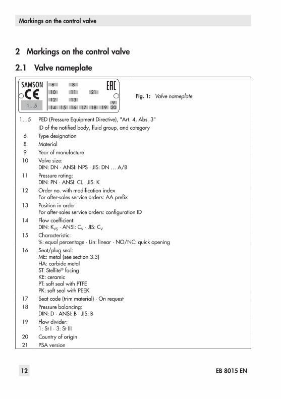
Fig. 1: Valve nameplate
1…5 PED (Pressure Equipment Directive), "Art. 4, Abs. 3"ID of the notified body, fluid group, and category
6 Type designation8 Material9 Year of manufacture10 Valve size:
DIN: DN · ANSI: NPS · JIS: DN … A/B11 Pressure rating:
DIN: PN · ANSI: CL · JIS: K12 Order no. with modification index
For after-sales service orders: AA prefix13 Position in order
For after-sales service orders: configuration ID14 Flow coefficient:
DIN: KVS · ANSI: CV · JIS: CV
15 Characteristic:%: equal percentage · Lin: linear · NO/NC: quick opening
16 Seat/plug seal:ME: metal (see section 3.3)HA: carbide metalST: Stellite® facingKE: ceramicPT: soft seal with PTFEPK: soft seal with PEEK
17 Seat code (trim material) · On request18 Pressure balancing:
DIN: D · ANSI: B · JIS: B19 Flow divider:
1: St I · 3: St III20 Country of origin21 PSA version
EB 8015 EN 13
Markings on the control valve
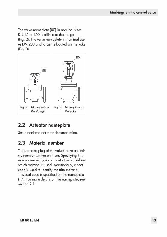
The valve nameplate (80) in nominal sizes DN 15 to 150 is affixed to the flange (Fig. 2). The valve nameplate in nominal siz-es DN 200 and larger is located on the yoke (Fig. 3).
80
80
Fig. 2: Nameplate on the flange
Fig. 3: Nameplate on the yoke
2.2 Actuator nameplateSee associated actuator documentation.
2.3 Material numberThe seat and plug of the valves have an arti-cle number written on them. Specifying this article number, you can contact us to find out which material is used. Additionally, a seat code is used to identify the trim material. This seat code is specified on the nameplate (17). For more details on the nameplate, see section 2.1.

14 EB 8015 EN
Design and principle of operation
3 Design and principle of oper-ation
The single-seated Type 3241 Globe Valve is preferably combined with a SAMSON Type 3271 or Type 3277 Pneumatic Actuator (see Fig. 4). It can also be combined with other actuators.The seat (4) and plug with plug stem (5) are assembled in the body (1). The plug stem is connected to the actuator stem (A7) by the stem connector clamps (A26) and is sealed by a spring-loaded V-ring packing (16). The springs in the pneumatic actuator (A) are lo-cated either above or below the diaphragm depending on the selected fail-safe action (see section 3.1). A change in the signal pressure acting on the diaphragm causes the plug to move. The actuator size is deter-mined by the diaphragm area.The medium flows through the valve in the direction indicated by the arrow. A rise in signal pressure causes the force acting on the diaphragm in the actuator to increase. The springs are compressed. Depending on the selected direction of action, the actuator stem retracts or extends. As a result, the plug position in the seat changes and determines the flow rate through the valve.

EB 8015 EN 15
Design and principle of operation
154
16
11
384
8
910
142
17
92
A
284
10
A269
8
16
11
A8
A7
1417
1
45
1 Body2 Flange3 Yoke4 Seat5 Plug (with plug stem)8 Threaded bushing (packing nut)9 Stem connector nut10 Lock nut11 Spring14 Nuts16 Packing17 Body gasket84 Travel indicator scale92 Castellated nutA ActuatorA7 Actuator stemA8 Ring nutA26 Stem connector clamps
Fig. 4: Type 3241‑1 Control Valve with Type 3271 Pneumatic Actuator, body up to DN 150
Fig. 5: Type 3241 Valve, body DN 200 to 300
16 EB 8015 EN
Design and principle of operation
3.1 Fail-safe positionsThe fail-safe position depends on the actua-tor used.Depending on how the compression springs are arranged in the pneumatic actuator, the valve has two different fail-safe positions:
Actuator stem extends (FA)When the signal pressure is reduced or the air supply fails, the springs move the actua-tor stem downward and close the valve. The valve opens when the signal pressure is in-creased enough to overcome the force exert-ed by the springs.
Actuator stem retracts (FE)When the signal pressure is reduced or the air supply fails, the springs move the actua-tor stem upwards and open the valve. The valve closes when the signal pressure is in-creased enough to overcome the force exert-ed by the springs.
The actuator's direction of action can be re‑versed, if required. Refer to the mounting and operating instructions of the pneumatic actuator:u EB 8310‑X for Type 3271 and Type 3277
3.2 VersionsThe modular design allows an insulating sec-tion or metal bellows to be fitted to the stan-dard valve version.
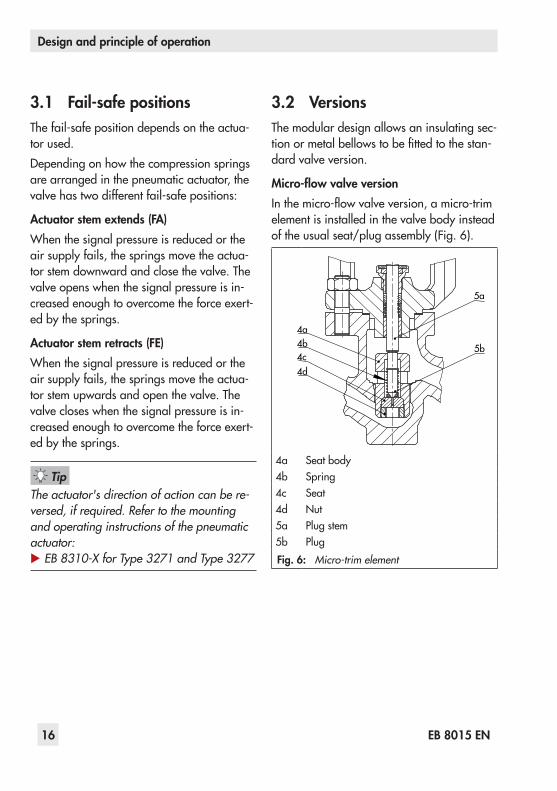
Micro-flow valve versionIn the micro-flow valve version, a micro-trim element is installed in the valve body instead of the usual seat/plug assembly (Fig. 6).
5b
5a
4d4c4b4a
4a Seat body4b Spring4c Seat4d Nut5a Plug stem5b PlugFig. 6: Micro‑trim element
Tip

EB 8015 EN 17
Design and principle of operation
ActuatorsIn these instructions, the preferable combina-tion with a Type 3271 or Type 3277 Pneu-matic Actuator is described. The pneumatic actuator (with or without handwheel) can be replaced by another pneumatic actuator in a different size, but with the same travel.
Î Observe the maximum permissible actu-ator force.
If the travel range of the actuator is larger than the travel range of the valve, the spring assembly in the actuator must be preloaded so that the travel ranges match. See associ‑ated actuator documentation.
The basic pneumatic actuator can be re-placed by a pneumatic actuator with addi-tional handwheel or by an electric actuator.
3.3 Technical dataThe nameplates on the valve and actuator provide information on the control valve ver-sion. See section 2.1 and the actuator docu-mentation.
More information is available in Data Sheet u T 8015.
ComplianceThe Type 3241 Valve bears both the CE and EAC marks of conformity.
Temperature rangeDepending on the version, the control valve is designed for a temperature range from –10 to +220 °C. The use of an insulating section or bellows seal extends the tempera-ture range from –196 to +450 °C.
Leakage classDepending on the version, the following leakage class applies:
Seal (16 on nameplate) ME, ST ME, ST PT, PK
Pressure balancing (18 on nameplate) – D/B –
Leakage class (according to IEC 60534-4)
Min. IV Min. IV VI
Noise emissionSAMSON is unable to make general state-ments about noise emission as it depends on the valve version, plant facilities, and pro-cess medium. On request, SAMSON can perform calculations according to IEC 60534, Part 8-3 and Part 8-4 or VDMA 24422 (edition 89).
Risk of hearing loss or deafness due to loud noise.Wear hearing protection when working near the valve.
Note
Note
WARNING!
18 EB 8015 EN
Design and principle of operation
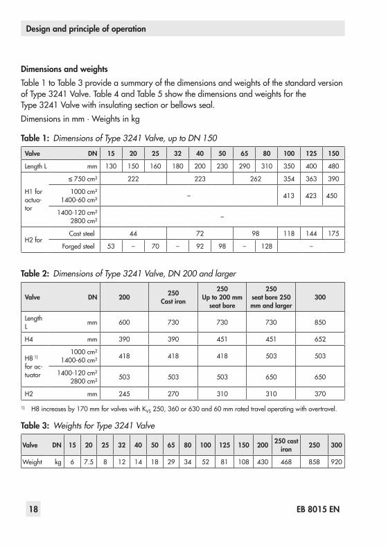
Dimensions and weightsTable 1 to Table 3 provide a summary of the dimensions and weights of the standard version of Type 3241 Valve. Table 4 and Table 5 show the dimensions and weights for the Type 3241 Valve with insulating section or bellows seal.Dimensions in mm · Weights in kg
Table 1: Dimensions of Type 3241 Valve, up to DN 150
Valve DN 15 20 25 32 40 50 65 80 100 125 150
Length L mm 130 150 160 180 200 230 290 310 350 400 480
H1 for actua-tor
≤ 750 cm² 222 223 262 354 363 390
1000 cm²1400-60 cm² – 413 423 450
1400-120 cm²2800 cm² –
H2 forCast steel 44 72 98 118 144 175
Forged steel 53 – 70 – 92 98 – 128 –
Table 2: Dimensions of Type 3241 Valve, DN 200 and larger
Valve DN 200 250Cast iron
250Up to 200 mm
seat bore
250seat bore 250 mm and larger
300
Length L mm 600 730 730 730 850
H4 mm 390 390 451 451 652
H8 1) for ac-tuator
1000 cm²1400-60 cm² 418 418 418 503 503
1400-120 cm²2800 cm² 503 503 503 650 650
H2 mm 245 270 310 310 370
1) H8 increases by 170 mm for valves with KVS 250, 360 or 630 and 60 mm rated travel operating with overtravel.
Table 3: Weights for Type 3241 Valve
Valve DN 15 20 25 32 40 50 65 80 100 125 150 200 250 cast iron 250 300
Weight kg 6 7.5 8 12 14 18 29 34 52 81 108 430 468 858 920
EB 8015 EN 19
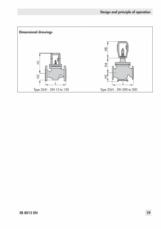
Design and principle of operation
Dimensional drawingsH1
H2
L
H8H4
H2
L
Type 3241 · DN 15 to 150 Type 3241 · DN 200 to 300
20 EB 8015 EN
Design and principle of operation
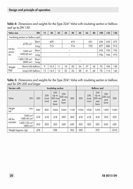
Table 4: Dimensions and weights for the Type 3241 Valve with insulating section or bellows seal up to DN 150
Valve size DN 15 20 25 32 40 50 65 80 100 125 150
Insulating section or bellows seal
H4 for actua-tor
≤750 cm²Short 409 410 451 636 645 672
Long 713 714 755 877 886 913
1000 cm²1400-60 cm²
Short – 695 705 732
Long – 936 946 973
1400-120 cm²2800 cm²
ShortLong –
Weight [kg]
Short/with bellows 9 10.5 11 18 20 24 37 42 70 106 138
Long/with bellows 13 14.5 15 22 24 28 41 46 78 114 146
Table 5: Dimensions and weights for the Type 3241 Valve with insulating section or bellows seal for DN 200 and larger
Version with Insulating section Bellows seal
Valve DN 200250 (cast iron)
250Up to
200 mm seat bore
250250 mm
seat bore
300 200250 (cast iron)
250Up to
200 mm seat bore
250250 mm
seat bore
300
Height H4
mm 830 830 1065 1065 1150 1036 1036 1492 1492 1520
H8 for actuator
1000 cm²1400-60 cm² 418 418 418 503 503 418 418 418 503 503
1400-120 cm²2800 cm² 503 503 503 650 650 503 503 503 650 650
Weight (approx. kg) 478 928 963 520 975 1010

EB 8015 EN 21
Design and principle of operation
Dimensional drawingsH4
H8H4
Type 3241 with insulating section or bellows seal · DN 15 to 150
Type 3241 with insulating section or bellows seal · DN 200 to 300
Refer to the following data sheets for more dimensions and weights:u T 8015 for valves with bellows seal, insulating section or heating jacketThe associated actuator documentation applies to actuators, e.g. for SAMSON pneumatic actuators:u T 8310‑1 for Type 3271 and Type 3277 Actuators up to 750 cm² actuator areau T 8310‑2 for Type 3271 Actuator with 1000 cm² actuator area and largeru T 8310‑3 for Type 3271 Actuator with 1400‑60 cm² actuator area
Note

22 EB 8015 EN
Preparation
4 PreparationAfter receiving the shipment, proceed as fol-lows:1. Check the scope of delivery. Compare
the shipment received against the deliv-ery note.
2. Check the shipment for transportation damage. Report any damage to SAMSON and the forwarding agent (re-fer to delivery note).
4.1 Unpacking
Do not remove the packaging until immedi‑ately before installing the valve into the pipe‑line.
Proceed as follows to lift and install the valve:1. Remove the packaging from the valve.2. Dispose of the packaging in accordance
with the valid regulations.
Risk of valve damage due to foreign parti‑cles entering the valve.The protective caps fitted on the valve's inlet and outlet prevent foreign particles from en‑tering the valve and damaging it.Do not remove the protective caps until im‑mediately before installing the valve into the pipeline.
4.2 Transporting and lifting
Hazard due to suspended loads falling.Stay clear of suspended or moving loads.
Risk of lifting equipment tipping and risk of damage to lifting accessories due to exceed‑ing the rated lifting capacity. − Only use approved lifting equipment and accessories whose minimum lifting capaci‑ty is higher than the weight of the valve (including actuator, if applicable). − Refer to section 3.3 or Data Sheet u T 8015 for weights.
Risk of personal injury due to control valve tipping. − Observe the valve's center of gravity. − Secure the valve against tipping over or turning.
Note
NOTICE!
DANGER!
WARNING!
WARNING!
EB 8015 EN 23
Preparation
Risk of valve damage due to incorrectly at‑tached slings.The welded‑on lifting eyelet on SAMSON actuators is only intended for mounting and removing the actuator as well as lifting the actuator without valve. Do not use this lifting eyelet to lift the entire control valve assembly. − When lifting the control valve, make sure that the slings attached to the valve body bear the entire load. − Do not attach load‑bearing slings to the actuator, handwheel or any other parts. − Observe lifting instructions (see sec‑tion 4.2.2).
SAMSON's After‑sales Service department can provide more detailed transport and lift‑ing instructions on request.
4.2.1 TransportingThe control valve can be transported using lifting equipment (e.g. crane or forklift).
Î Leave the control valve in its transport container or on the pallet to transport it.
Î Observe the transport instructions.
Transport instructions − Protect the control valve against external
influences (e.g. impact). − Do not damage the corrosion protection
(paint, surface coatings). Remove any damage immediately.
− Protect the control valve against moisture and dirt.
− The permissible transportation tempera-ture of standard control valves is –20 to +65 °C.
Contact SAMSON's After‑sales Service de‑partment for the transportation temperatures of other valve versions.
4.2.2 LiftingTo install a large valve into the pipeline, use lifting equipment (e.g. crane or forklift) to lift it.
Lifting instructions − Secure slings against slipping. − Make sure the slings can be removed
from the valve once it has been installed into the pipeline.
NOTICE!
Tip
Note

24 EB 8015 EN
Preparation
Fig. 7: Lifting points on the control valve: up to DN 150 (left) and with welding ends (middle) · DN 150 and larger with additional lifting eyelet on the actuator (right)
− Prevent the control valve from tilting or tipping.
− Do not leave loads suspended when in-terrupting work for longer periods of time.
− Make sure that the axis of the pipeline is always horizontal during lifting and the axis of the plug stem is always vertical.
− Make sure that the additional sling be-tween the lifting eyelet and rigging equipment (hook, shackle etc.) does not bear any load when lifting valves larger than DN 150. The sling only protects the
control valve from tilting while being lift-ed. Before lifting the control valve, tight-en the sling.

EB 8015 EN 25
Preparation
Version with flanges1. Attach one sling to each flange of the
body and to the rigging equipment (e.g. hook) of the crane or forklift (see Fig. 7).
2. DN 150 and larger: Attach another sling to the lifting eyelet on the actuator and to the rigging equipment.
3. Carefully lift the control valve. Check whether the lifting equipment and acces-sories can bear the weight.
4. Move the control valve at an even pace to the site of installation.
5. Install the valve into the pipeline (see sec-tion 5.2.3).
6. After installation in the pipeline, check whether the flanges are bolted tight and the valve in the pipeline holds.
7. Remove slings.
Version with welding ends1. Attach one sling to each welding end of
the body and to the rigging equipment (e.g. hook) of the crane or forklift (see Fig. 7).
2. Secure the slings attached to the body against slipping using a connector.
3. DN 150 and larger: Attach another sling to the lifting eyelet on the actuator and to the rigging equipment.
4. Carefully lift the control valve. Check whether the lifting equipment and acces-sories can bear the weight.
5. Move the control valve at an even pace to the site of installation.
6. Install the valve into the pipeline (see sec-tion 5.2.3).
7. After installation in the pipeline, check whether the weld seams hold.
8. Remove connector and slings.
We recommend using a hook with safety latch (see Fig. 7). The safety latch prevents the slings from slipping during lifting and transporting.
Tip

26 EB 8015 EN
Preparation
4.3 Storage
Risk of valve damage due to improper stor‑age. − Observe storage instructions. − Avoid long storage times. − Contact SAMSON in case of different stor‑age conditions or long storage periods.
We recommend regularly checking the con‑trol valve and the prevailing storage condi‑tions during long storage times.
Storage instructions − Protect the control valve against external
influences (e.g. impact). − Do not damage the corrosion protection
(paint, surface coatings). Remove any damage immediately.
− Protect the control valve against moisture and dirt. Store it at a relative humidity of less than 75 %. In damp spaces, prevent condensation. If necessary, use a drying agent or heating.
− Make sure that the ambient air is free of acids or other corrosive media.
− The permissible storage temperature of standard control valves is –20 to +65 °C.
Contact SAMSON's After‑sales Service de‑partment for the storage temperatures of oth‑er valve versions.
− Do not place any objects on the control valve.
Special storage instructions for elastomersElastomer, e.g. actuator diaphragm − To keep elastomers in shape and to pre-
vent cracking, do not bend them or hang them up.
− We recommend a storage temperature of 15 °C for elastomers.
− Store elastomers away from lubricants, chemicals, solutions, and fuels.
SAMSON's After‑sales Service department can provide more detailed storage instruc‑tions on request.
NOTICE!
Note
Note
Tip

EB 8015 EN 27
Preparation
4.4 Preparation for installationProceed as follows:
Î Flush the pipelines.
The plant engineering company is responsi‑ble for cleaning the pipelines in the plant.
Î Check the valve to make sure it is clean. Î Check the valve for damage. Î Check to make sure that the type desig-nation, valve size, material, pressure rat-ing and temperature range of the valve match the plant conditions (size and pressure rating of the pipeline, medium temperature etc.).
Î For steam applications, make sure that the pipelines are dry. Moisture will dam-age the inside of the valve.
Î Check any mounted pressure gauges to make sure they function.
Î When the valve and actuator are al-ready assembled, check the tightening torques of the bolted joints (u AB 0100). Components may loosen during trans-port.
Note
28 EB 8015 EN
Mounting and start-up
5 Mounting and start-upSAMSON valves are delivered ready for use. In special cases, the valve and actuator are delivered separately and must be assem-bled on site. The procedure to mount and start up the valve are described in the follow-ing.
Risk of valve damage due to excessively high or low tightening torques.Observe the specified torques on tightening control valve components. Excessively tight‑ened torques lead to parts wearing out quicker. Parts that are too loose may cause leakage.Observe the specified tightening torques (u AB 0100).
Risk of valve damage due to the use of un‑suitable tools.Only use tools approved by SAMSON (u AB 0100).
5.1 Mounting the actuator onto the valve
Proceed as described in the actuator docu-mentation if the valve and actuator have not been assembled by SAMSON:
Versions with V-port plugEach V-port plug has three V-shaped ports. Depending on the valve size, the size of the
symmetrically arranged V-shaped ports var-ies. The process medium in the valve flows through the V-shaped ports as soon as the plug is lifted out of the seat (i.e. the valve opens).1. Before mounting the actuator, determine
which V-shaped port is uncovered first when the plug is lifted out of the seat.
Usually, this is the largest V‑shaped port.
2. On mounting the actuator, make sure that the V-shaped port uncovered first faces toward the valve outlet.
Risk of damage to wall of valve body due to incorrectly diverted jet stream.The process medium cannot flow unob‑structed through the valve when the V‑port plug has been installed incorrectly. This will result in the process medium hitting the body wall, which may lead to severe valve dam‑age.Make sure the V‑port plug is installed correctly.
− Remove the mounted actuator before mounting the other actuator (see associat‑ed actuator documentation). − Preloading the actuator springs increases the thrust of a pneumatic actuator and re‑duces the travel range of the actuator (see associated actuator documentation).
NOTICE!
NOTICE!
Tip
NOTICE!
Note

EB 8015 EN 29
Mounting and start-up
5.2 Installing the valve into the pipeline
5.2.1 Checking the installation conditions
Pipeline routingThe inlet and outlet lengths vary depending on the process medium. To ensure the control valve functions properly, follow the installa-tion instructions given below:
Î Observe the inlet and outlet lengths (see Table 6). Contact SAMSON if the valve conditions or states of the medium pro-cess deviate.
Î Install the valve free of stress and with the least amount of vibrations as possible. If necessary, attach supports to the valve.
Î Install the valve allowing sufficient space to remove the actuator and valve or to perform service and repair work on them.
Mounting positionGenerally, we recommend installing the valve with the actuator upright and on top of the valve.In the following versions, the valve must be installed with the actuator on top: − Valves in DN 100 and larger − Valves with insulating section for low
temperatures below –10 °C Î Contact SAMSON if the mounting posi-tion is not as specified here.
Support or suspensionDepending on the valve version and mount-ing position, the control valve and pipeline must be supported or suspended. The plant engineering company is responsible in this case.
Premature wear and leakage due to insuffi‑cient support or suspension.In the following versions, the control valve must be supported or suspended: − Valves that are not installed with the actua‑tor upright on top of the valve.
Attach a suitable support or suspension to the valve.
Vent plugVent plugs are screwed into the exhaust air ports of pneumatic and electropneumatic de-vices. They ensure that any exhaust air that forms can be vented to the atmosphere (to avoid excess pressure in the device). Further-more, the vent plugs allow air intake to pre-vent a vacuum from forming in the device.
Î Locate the vent plug on the opposite side to the workplace of operating personnel.
Î On mounting valve accessories, make sure that they can be operated from the workplace of the operating personnel.
The workplace of operating personnel is the location from which the valve, actuator and any mounted valve accessories can be ac‑cessed to operate them.
NOTICE!
Note

30 EB 8015 EN
Mounting and start-up
5.2.2 Additional fittingsStrainersWe recommend installing a SAMSON strainer upstream of the valve. It prevents sol-id particles in the process medium from damaging the valve.
Bypass and shut-off valvesWe recommend installing a shut-off valve both upstream of the strainer and down-
stream of the valve and setting up a bypass line. The bypass line ensures that the plant does not need to be shut down for service and repair work on the valve.
InsulationOnly insulate control valves with insulating section or bellows seal up to the bonnet flange of the valve body for medium tem-peratures below 0 °C or above 220 °C.
Table 6: Inlet and outlet lengths
Q
a x DN b x DN
State of process medium Valve conditions Inlet length a Outlet length b
GasMa ≤ 0.3 2 4
0.3 ≤ Ma ≤ 0.7 2 10
Vapor
Ma ≤ 0.3 1) 2 40.3 ≤ Ma ≤ 0.7 1) 2 10Saturated steam (percentage of conden-sate > 5 %) 2 20
Liquid
Free of cavitation/w < 10 m/s 2 4Cavitation producing noise/w ≤ 3 m/s 2 4Cavitation producing noise/3 < w < 5 m/s 2 10Critical cavitation/w ≤ 3 m/s 2 10Critical cavitation/3 < w < 5 m/s 2 20
Flashing – 2 20Multi-phase – 10 20
1) No saturated steam
Q Flow ratea Inlet lengthb Outlet length
EB 8015 EN 31
Mounting and start-up
Do not insulate valves mounted to comply with NACE MR 0175 requirements and which have nuts and bolts not suitable for sour gas environments.
Test connectionVersions with bellows seal fitted with a test connection (G 1/8) at the top flange allow the sealing ability of the bellows to be moni-tored.Particularly for liquids and vapors, we rec-ommend installing a suitable leakage indica-tor (e.g. a contact pressure gauge, an outlet to an open vessel or an inspection glass).
Risk of personal injury due to components under pressure and process medium escap‑ing under pressure.Do not loosen the screw of the test connec‑tion while the valve is in operation.
Safety guardTo reduce the crush hazard arising from moving parts (actuator and plug stem), a safety guard can be installed.
Noise emissionTrims with flow dividers can be used to re-duce noise emission (see u T 8081).
5.2.3 Installing the control valve
Version with flanges1. Close the shut-off valve in the pipeline
while the valve is being installed.
2. Remove the protective caps from the valve ports before installing the valve.
3. Lift the valve using suitable lifting equip-ment to the site of installation (see sec-tion 4.2.2). Observe the flow direction through the valve. The arrow on the valve indicates the direction of flow.
4. Make sure that the correct flange gaskets are used.
5. Bolt the pipe to the valve free of stress.6. Depending on the field of application,
allow the valve to cool down or heat up to reach ambient temperature before start up.
7. Slowly open the shut-off valve in the pipeline after the valve has been in-stalled.
Risk of valve damage due to a sudden pres‑sure increase and resulting high flow veloci‑ties.Slowly open the shut‑off valve in the pipeline during start‑up.
8. Check the valve to ensure it functions properly.
Version with welding ends1. Proceed as described for Version with
flanges (steps 1 to 3).2. Completely retract the actuator stem to
protect the plug from sparks during weld-ing.
3. Weld the valve free of stress into the pipeline.
WARNING!
NOTICE!

32 EB 8015 EN
Mounting and start-up
4. Proceed as described for Version with flanges (steps 6 to 8).
5.3 Quick checkSAMSON valves are delivered ready for use. To test the valve's ability to function, the following quick checks can be performed:
Tight shut-off1. Close the valve.2. Slowly open the shut-off valve in the
pipeline.
Risk of valve damage due to a sudden pressure increase and resulting high flow velocities.Slowly open the shut‑off valve in the pipeline during start‑up.
3. Check the valve for leakage (visual in-spection).
Travel motionThe movement of the actuator stem must be linear and smooth.
Î Open and close the valve, observing the movement of the actuator stem.
Î Apply the maximum and minimum con-trol signals to check the end positions of the valve.
Î Check the travel reading at the travel in-dicator scale.
NOTICE!
EB 8015 EN 33
Mounting and start-up
Fail-safe position Î Shut off the signal pressure line. Î Check whether the valve moves to the fail-safe position.
Adjustable packing
A label on the flange (2) or yoke (3) indi‑cates whether an adjustable packing is in‑stalled.
1. Tighten the threaded bushing gradually (by turning it clockwise) until the packing seals the valve.
Risk of valve damage due to the threaded bushing tightened too far.Make sure that the plug stem can still move smoothly after the threaded bushing has been tightened.
2. Open and close the valve several times.3. Check the valve for leakage to the atmo-
sphere (visual inspection).4. Repeat steps 1 and 2 until the packing
completely seals the valve.
If the adjustable packing does not seal prop‑erly, contact SAMSON's After‑sales Service department.
Pressure testDuring the pressure test, make sure the fol-lowing conditions are met: − Retract the plug stem to open the valve. − Observe the maximum permissible pres-
sure for valve and plant.
The plant engineering company is responsi‑ble for performing the pressure test. SAMSON's After‑sales Service department can support you to plan and perform a pres‑sure test for your plant.
Tip
NOTICE!
Note
Note
34 EB 8015 EN
Operation
6 OperationImmediately after completing mounting and start-up (see section 5), the valve is ready for use.
Crush hazard arising from moving parts (ac‑tuator and plug stem).Do not insert hands or finger into the yoke while the valve is in operation.
Risk of personal injury when the actuator vents.Wear eye protection when working in close proximity to the control valve.
Risk of burn injuries due to hot or cold com‑ponents and pipelines.Depending on the process medium, valve components, and pipelines may get very hot or cold and cause burn injuries.Wear protective clothing and gloves.
Operation disturbed by a blocked actuator or plug stem.Do not impede the movement of the actuator or plug stem by inserting objects into their path.
6.1 Working in manual modeValves fitted with actuators with a handwheel can be manually closed or opened in case of supply air failure.
Î For normal closed-loop operation, move the handwheel to the neutral position.WARNING!
WARNING!
WARNING!
NOTICE!

EB 8015 EN 35
Operation
36 EB 8015 EN
Servicing
7 ServicingThe control valve is subject to normal wear, especially at the seat, plug, and packing. Depending on the operating conditions, check the valve at regular intervals to pre-vent possible failure before it can occur.
SAMSON's After‑sales Service department can support you to draw up an inspection plan for your plant.
We recommend removing the valve from the pipeline or service or repair work (see sec-tion 9.2).
Risk of bursting in pressure equipment.Control valves and pipelines are pressure equipment. Improper opening can lead to bursting of the valve. − Before starting any work on the control valve, depressurize all plant sections con‑cerned and the valve. − Drain the process medium from all the plant sections concerned as well as the valve. − Wear personal protective equipment.
Risk of personal injury due to residual pro‑cess medium in the valve.While working on the valve, residual process medium can escape and, depending on its properties, may lead to personal injury, e.g. (chemical) burns.
Wear protective clothing, gloves, and eye‑wear.
Risk of burn injuries due to hot or cold com‑ponents and pipeline.Valve components and the pipeline may be‑come very hot or cold. Risk of burn injuries. − Allow components and pipelines to cool down or heat up. − Wear protective clothing and gloves.
Risk of valve damage due to incorrect servic‑ing or repair.Service and repair work must only be per‑formed by trained staff.
Risk of valve damage due to excessively high or low tightening torques.Observe the specified torques on tightening control valve components. Excessively tight‑ened torques lead to parts wearing out quicker. Parts that are too loose may cause leakage.Observe the specified tightening torques (u AB 0100).
Risk of valve damage due to the use of un‑suitable tools.Only use tools approved by SAMSON (u AB 0100).
Tip
DANGER!
WARNING!
WARNING!
NOTICE!
NOTICE!
NOTICE!

EB 8015 EN 37
Servicing
Risk of valve damage due to the use of un‑suitable lubricants.Only use lubricants approved by SAMSON (u AB 0100).
The control valve was checked by SAMSON before it left the factory. − Certain test results (seat leakage and leak test) certified by SAMSON lose their validi‑ty when the valve body or actuator hous‑ing is opened. − The product warranty becomes void if ser‑vicing or repair work not described in these instructions is performed without pri‑or agreement by SAMSON's After‑sales Service department. − Only use original spare parts by SAMSON, which comply with the original specifications.
7.1 Replacing the gasket
NOTICERisk of control valve damage due to incorrect service or repair.The gasket can only be replaced when all the following conditions are met: − Nominal size of the valve is ≤DN 150. − The valve does not have a bal‑anced plug.
To replace the gasket in other valve versions, contact SAMSON's After‑sales Service department.
7.1.1 Standard version1. Remove the actuator from the valve. See
associated actuator documentation.2. Undo the body nuts (14) gradually in a
criss-cross pattern.3. Lift the flange (2) and plug with plug
stem (5) off the body (1).4. Remove the flat gasket (17). Carefully
clean the sealing faces in the valve body (1) and on the flange (2).
5. Insert a new gasket (17) into the body.6. Place the flange (2) onto the body.
Version with V-port plug: place the flange (2) onto the valve body, making sure that the largest V-shaped port of the V-port plug faces toward the valve outlet. See section 5.1.
7. Press the plug (5) firmly into the seat (4), while fastening down the flange (2) with
NOTICE!
Note
38 EB 8015 EN
Servicing
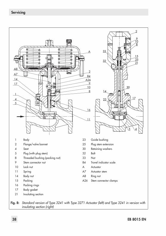
1 Body2 Flange/valve bonnet4 Seat5 Plug (with plug stem)8 Threaded bushing (packing nut)9 Stem connector nut10 Lock nut11 Spring14 Body nut15 Packing16 Packing rings17 Body gasket21 Insulating section
23 Guide bushing25 Plug stem extension30 Retaining washers32 Bolt33 Nut84 Travel indicator scaleA ActuatorA7 Actuator stemA8 Ring nutA26 Stem connector clamps
A
284
10
A269
8
16
11
A8
A7
1417
1
45
14
2
15
21
17
33
9
25
108
30
32
23
5 4
Fig. 8: Standard version of Type 3241 with Type 3271 Actuator (left) and Type 3241 in version with insulating section (right)

EB 8015 EN 39
Servicing
the body nuts (14). Tighten the nuts gradually in a criss-cross pattern. Ob-serve tightening torques.
8. Mount actuator. See associated actuator documentation.
9. Adjust lower or upper signal bench range. See associated actuator docu-mentation.
7.1.2 Version with insulating section or bellows seal
1. Remove the actuator from the valve. See associated actuator documentation.
2. Undo the body nuts (14) gradually in a criss-cross pattern.
3. Lift the insulating section (21) with valve bonnet (2) and plug with plug stem (5) off the body (1).
4. Remove the flat gasket (17). Carefully clean the sealing faces in the valve body (1) and on the insulating section (21).
5. Insert a new gasket (17) into the body.6. Place the insulating section (21) with
valve bonnet (2) and plug with plug stem (5) onto the body.Version with V-port plug: place the as-sembly onto the valve body, making sure that the largest V-shaped port of the V-port plug faces toward the valve outlet. See section 5.1.
7. Press the plug (5) firmly into the seat (4), while fastening down the insulating sec-tion (21) with the body nuts (14). Tighten the nuts gradually in a criss-cross pat-tern. Observe tightening torques.
8. Mount actuator. See associated actuator documentation.
9. Adjust lower or upper signal bench range. See associated actuator docu-mentation.
7.2 Replacing the packing
Risk of control valve damage due to incorrect service or repair.The packing can only be replaced when all the following conditions are met: − Nominal size of the valve is ≤DN 150. − The valve does not have a balanced plug. − The valve does not have a bellows seal. − The standard or ADSEAL packing is in‑stalled in the valve.
To replace the packing in other valve ver‑sions, contact SAMSON's After‑sales Service department.
7.2.1 Standard versionStandard packing (PTFE)1. Remove the actuator from the valve. See
associated actuator documentation.2. Undo the body nuts (14) gradually in a
criss-cross pattern.3. Lift the flange (2) and plug with plug
stem (5) off the body (1).4. Unthread the stem connector nut (9) and
lock nut (10) from the plug stem.5. Unscrew the threaded bushing (8).
NOTICE!
40 EB 8015 EN
Servicing
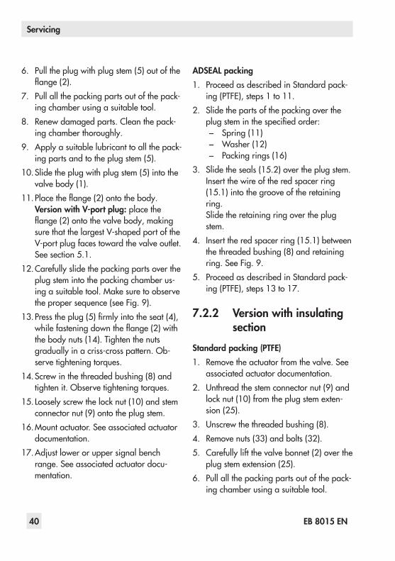
6. Pull the plug with plug stem (5) out of the flange (2).
7. Pull all the packing parts out of the pack-ing chamber using a suitable tool.
8. Renew damaged parts. Clean the pack-ing chamber thoroughly.
9. Apply a suitable lubricant to all the pack-ing parts and to the plug stem (5).
10. Slide the plug with plug stem (5) into the valve body (1).
11. Place the flange (2) onto the body.Version with V-port plug: place the flange (2) onto the valve body, making sure that the largest V-shaped port of the V-port plug faces toward the valve outlet. See section 5.1.
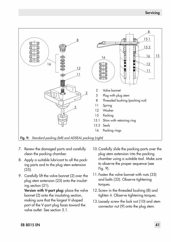
12. Carefully slide the packing parts over the plug stem into the packing chamber us-ing a suitable tool. Make sure to observe the proper sequence (see Fig. 9).
13. Press the plug (5) firmly into the seat (4), while fastening down the flange (2) with the body nuts (14). Tighten the nuts gradually in a criss-cross pattern. Ob-serve tightening torques.
14. Screw in the threaded bushing (8) and tighten it. Observe tightening torques.
15. Loosely screw the lock nut (10) and stem connector nut (9) onto the plug stem.
16. Mount actuator. See associated actuator documentation.
17. Adjust lower or upper signal bench range. See associated actuator docu-mentation.
ADSEAL packing1. Proceed as described in Standard pack-
ing (PTFE), steps 1 to 11.2. Slide the parts of the packing over the
plug stem in the specified order: − Spring (11) − Washer (12) − Packing rings (16)
3. Slide the seals (15.2) over the plug stem.Insert the wire of the red spacer ring (15.1) into the groove of the retaining ring.Slide the retaining ring over the plug stem.
4. Insert the red spacer ring (15.1) between the threaded bushing (8) and retaining ring. See Fig. 9.
5. Proceed as described in Standard pack-ing (PTFE), steps 13 to 17.
7.2.2 Version with insulating section
Standard packing (PTFE)1. Remove the actuator from the valve. See
associated actuator documentation.2. Unthread the stem connector nut (9) and
lock nut (10) from the plug stem exten-sion (25).
3. Unscrew the threaded bushing (8).4. Remove nuts (33) and bolts (32).5. Carefully lift the valve bonnet (2) over the
plug stem extension (25).6. Pull all the packing parts out of the pack-
ing chamber using a suitable tool.
EB 8015 EN 41
Servicing
7. Renew the damaged parts and carefully clean the packing chamber.
8. Apply a suitable lubricant to all the pack-ing parts and to the plug stem extension (25).
9. Carefully lift the valve bonnet (2) over the plug stem extension (25) onto the insulat-ing section (21).Version with V-port plug: place the valve bonnet (2) onto the insulating section, making sure that the largest V-shaped port of the V-port plug faces toward the valve outlet. See section 5.1.
10. Carefully slide the packing parts over the plug stem extension into the packing chamber using a suitable tool. Make sure to observe the proper sequence (see Fig. 9).
11. Fasten the valve bonnet with nuts (33) and bolts (32). Observe tightening torques.
12. Screw in the threaded bushing (8) and tighten it. Observe tightening torques.
13. Loosely screw the lock nut (10) and stem connector nut (9) onto the plug stem.
16
8
12
16
15.2
15
15.1
11
2 Valve bonnet5 Plug with plug stem8 Threaded bushing (packing nut)11 Spring12 Washer15 Packing
15.1 Shim with retaining ring15.2 Seals16 Packing rings
16
8
12
11
2
5
Fig. 9: Standard packing (left) and ADSEAL packing (right)

42 EB 8015 EN
Servicing
14. Mount actuator. See associated actuator documentation.
15. Adjust lower or upper signal bench range. See associated actuator docu-mentation.
ADSEAL packing1. Proceed as described in Standard pack-
ing (PTFE), steps 1 to 9.2. Slide the parts of the packing over the
plug stem extension in the specified or-der:
− Spring (11) − Washer (12) − Packing rings (16)
3. Slide the seals (15.2) over the plug stem extension.Insert the wire of the red spacer ring (15.1) into the groove of the retaining ring.Slide the retaining ring over the plug stem extension.
4. Insert the red spacer ring (15.1) between the threaded bushing (8) and retaining ring. See Fig. 9.
5. Proceed as described in Standard pack-ing (PTFE), steps 11 to 15.
7.3 Replacing the seat and plug
Risk of control valve damage due to incorrect service or repair.Seat and plug can only be replaced when all the following conditions are met:
− Nominal size of the valve is ≤DN 150. − The valve does not have a balanced plug. − The valve does not have a bellows seal. − The standard or ADSEAL packing is in‑stalled in the valve.
To replace seat and plug in other valve ver‑sions, contact SAMSON's After‑sales Service department.
Risk of damage to the facing of the seat and plug due to incorrect service or repair.Always replace both the seat and plug.
When replacing the seat and plug, we also recommend replacing the packing. See sec‑tion 7.2.
7.3.1 Standard version1. Remove the actuator from the valve. See
associated actuator documentation.2. Undo the body nuts (14) gradually in a
criss-cross pattern.3. Lift the flange (2) and plug with plug
stem (5) off the body (1).4. Replace gasket as described in sec-
tion 7.1.1.5. Unthread the stem connector nut (9) and
lock nut (10) from the plug stem.6. Unscrew the threaded bushing (8).7. Pull the plug with plug stem (5) out of the
flange (2).
NOTICE!
NOTICE!
Tip

EB 8015 EN 43
Servicing
8. Pull all the packing parts out of the pack-ing chamber using a suitable tool.
9. Unscrew the seat (4) using a suitable tool.
10. Apply a suitable lubricant to the thread and the sealing cone of the new seat.
11. Screw in the seat (4). Observe tightening torques.
12. Apply a suitable lubricant to all the pack-ing parts and to the new plug stem (5).We recommend replacing the packing as well. See section 7.2.1.
13. Slide the new plug with plug stem (5) in-to the valve body (1).
14. Place the flange (2) onto the body.Version with V-port plug: place the flange (2) onto the valve body, making sure that the largest V-shaped port of the V-port plug faces toward the valve outlet. See section 5.1.
15. Carefully slide the packing parts over the plug stem into the packing chamber us-ing a suitable tool. Make sure to observe the proper sequence (see Fig. 9).
16. Press the plug (5) firmly into the seat (4), while fastening down the flange (2) with the body nuts (14). Tighten the nuts gradually in a criss-cross pattern. Ob-serve tightening torques.
17. Screw in the threaded bushing (8) and tighten it. Observe tightening torques.
18. Loosely screw the lock nut (10) and stem connector nut (9) onto the plug stem.
19. Mount actuator. See associated actuator documentation.
20. Adjust lower or upper signal bench range. See associated actuator docu-mentation.
44 EB 8015 EN
Servicing
7.3.2 Version with insulating section
1. Remove the actuator from the valve. See associated actuator documentation.
2. Unthread the stem connector nut (9) and lock nut (10) from the plug stem exten-sion (25).
3. Unscrew the threaded bushing (8).4. Remove nuts (33) and bolts (32).5. Carefully lift the valve bonnet (2) over the
plug stem extension (25).6. Pull all the packing parts out of the pack-
ing chamber using a suitable tool.7. Undo the body nuts (14) gradually in a
criss-cross pattern.8. Lift the insulating section (21) together
with the plug stem extension (25), plug stem and plug (5) off the body (1).
9. Replace gasket as described in sec-tion 7.1.2.
10. Make sure that the guide bushing (23) is not damaged. If necessary, replace the guide bushing using a suitable tool.
11. Unscrew the seat (4) using a suitable tool.
12. Apply a suitable lubricant to the thread and the sealing cone of the new seat.
13. Screw in the seat (4). Observe tightening torques.
14. Hold the plug and plug stem (5) station-ary using assembly pliers. Unscrew the plug stem extension (25) using a suitable tool and take it out of the insulating sec-tion (21).
15. Apply a suitable lubricant to all packing parts and the end of the plug stem of the new plug (5).We recommend replacing the packing as well. See section 7.2.2.
16. Make sure that the two washers (30) are still in the plug stem extension (25). Re-new the washer, if necessary.
17. Hold the new plug with plug stem (5) sta-tionary. Place on the insulating section (21). Screw the plug stem extension (25) onto the plug stem using a suitable tool. Observe tightening torques.
18. Place the insulating section (21) together with the plug stem extension (25), plug stem and plug (5) onto the body (1).Version with V-port plug: place the insu-lating section (21) onto the valve body, making sure that the largest V-shaped port of the V-port plug faces toward the valve outlet. See section 5.1.
19. Press the plug (5) firmly into the seat (4), while fastening down the insulating sec-tion (21) with the body nuts (14). Tighten the nuts gradually in a criss-cross pat-tern. Observe tightening torques.
20. Carefully lift the valve bonnet (2) over the plug stem extension (25) onto the insulat-ing section (21).
21. Carefully slide the packing parts over the plug stem extension into the packing chamber using a suitable tool. Make sure to observe the proper sequence (see Fig. 9).
EB 8015 EN 45
Servicing
22. Fasten the valve bonnet with nuts (33) and bolts (32). Observe tightening torques.
23. Screw in the threaded bushing (8) and tighten it. Observe tightening torques.
24. Loosely screw the lock nut (10) and stem connector nut (9) onto the plug stem.
25. Mount actuator. See associated actuator documentation.
26. Adjust lower or upper signal bench range. See associated actuator docu-mentation.
7.4 Preparation for return ship-ment
Defective valves can be returned to SAMSON for repair.Proceed as follows to return valves to SAMSON:1. Put the control valve out of operation (see
section 9).2. Decontaminate the valve. Remove any
residual process medium.3. Fill in the Declaration on Contamination,
which can be downloaded from our website at u www.samson.de > Services > Check lists for after sales service > Declaration on Contamination.
4. Send the valve together with the filled-in form to your nearest SAMSON subsidi-ary. SAMSON subsidiaries are listed on our website at u www.samson.de > Contact.
7.5 Ordering spare parts and operating supplies
Contact your nearest SAMSON subsidiary or the SAMSON After-sales Service depart-ment for information on spare parts, lubri-cants, and tools.
Spare partsSee section 10.3 for details on spare parts.
LubricantDetails on suitable lubricants can be found in the document u AB 0100.
ToolsDetails on suitable tools can be found in the document u AB 0100.

46 EB 8015 EN
Malfunctions
8 MalfunctionsDepending on the operating conditions, check the valve at certain intervals to prevent possi-ble failure before it can occur. Operators are responsible for drawing up an inspection plan.
SAMSON's After‑sales Service department can support you to draw up an inspection plan for your plant.
8.1 TroubleshootingMalfunction Possible reasons Recommended actionActuator or plug stem does not move on demand.
Actuator is blocked. Check attachment.Unblock the actuator.
Signal pressure too low Check the signal pressure.Check the signal pressure line for leakage.
Actuator or plug stem does not move through the whole range.
Signal pressure too low Check the signal pressure.Check the signal pressure line for leakage.
The valve leaks to the atmo-sphere (fugitive emissions).
The packing is defective. Replace packing (see sec-tion 7.2) or contact SAMSON's After-sales Service department.
Version with adjustable packing 1): packing not tightened correctly.
See section 5.3, Adjustable packing. Contact SAMSON's After-sales Service department when it continues to leak.
Version with bellows seal: the metal bellows seal is defective.
Contact SAMSON's After-sales Service department.
Flange joint loose or gasket worn out.
Check the flange joint.Replace gasket at the flanged joint (see section 7.1 or contact SAMSON's After-sales Service department).
Tip

EB 8015 EN 47
Malfunctions
8.2 Emergency actionUpon supply air or control signal failure, the valve moves to its fail-safe position (see sec-tion 3.1).Operators are responsible for emergency ac-tion to be taken in the plant.In the event of a valve malfunction:1. Close the shut-off valves upstream and
downstream of the control valve to stop the process medium from flowing through the valve.
2. Check the valve for damage. If neces-sary, contact SAMSON's After-sales Ser-vice department.
Putting the valve back into operation after a malfunction
Î Slowly open the shut-off valves. Allow the process medium to flow into the valve slowly.
Malfunction Possible reasons Recommended actionIncreased flow through closed valve (seat leakage)
Dirt or other foreign particles de-posited between the seat and plug.
Shut off the section of the pipe-line and flush the valve.
Valve trim, particularly with soft seat, is worn.
Replace seat and plug (see sec-tion 7.3 or contact SAMSON's After-sales Service department).
1) A label on the flange (2) or yoke (3) indicates whether an adjustable packing is installed.
Contact SAMSON's After‑sales Service department for malfunctions not listed in the table.Note

48 EB 8015 EN
Decommissioning and disassembly
9 Decommissioning and disas-sembly
Risk of bursting in pressure equipment.Control valves and pipelines are pressure equipment. Improper opening can lead to bursting of the valve. − Before starting any work on the control valve, depressurize all plant sections con‑cerned and the valve. − Drain the process medium from all the plant sections concerned as well as the valve. − Wear personal protective equipment.
Risk of personal injury due to residual pro‑cess medium in the valve.While working on the valve, residual process medium can escape and, depending on its properties, may lead to personal injury, e.g. (chemical) burns.Wear protective clothing, gloves, and eye‑wear.
Risk of burn injuries due to hot or cold com‑ponents and pipeline.Valve components and the pipeline may be‑come very hot or cold. Risk of burn injuries. − Allow components and pipelines to cool down or heat up. − Wear protective clothing and gloves.
9.1 DecommissioningTo decommission the control valve for service and repair work or disassembly, proceed as follows:1. Close the shut-off valves upstream and
downstream of the control valve to stop the process medium from flowing through the valve.
2. Completely drain the pipelines and valve.
3. Disconnect and lock the pneumatic air supply to depressurize the actuator.
4. If necessary, allow the pipeline and valve components to cool down or heat up.
9.2 Removing the valve from the pipeline
Version with flanges1. Put the control valve out of operation (see
section 9.1).2. Unbolt the flange joint.3. Remove the valve from the pipeline (see
section 4.2).
Version with welding ends1. Put the control valve out of operation (see
section 9.1).2. Cut the pipeline in front of the weld
seam.3. Remove the valve from the pipeline (see
section 4.2).
DANGER!
WARNING!
WARNING!

EB 8015 EN 49
Decommissioning and disassembly
9.3 Removing the actuator from the valve
See associated actuator documentation.
9.4 Disposal Î Observe local, national, and internation-al refuse regulations.
Î Do not dispose of components, lubri-cants, and hazardous substances togeth-er with your other household waste.
50 EB 8015 EN
Appendix
10 Appendix
10.1 After-sales serviceContact SAMSON's After-sales Service de-partment for support concerning servicing or repair work or when malfunctions or defects arise.
E-mailYou can reach the After-sales Service De-partment at [email protected].
Addresses of SAMSON AG and its subsid-iariesThe addresses of SAMSON AG, its subsid-iaries, representatives, and service facilities worldwide can be found on the SAMSON website, in all SAMSON product catalogs or on the back of these Mounting and Operat-ing Instructions.
Required specificationsPlease submit the following details: − Order number and position number in
the order − Type, model number, nominal size, and
valve version − Pressure and temperature of the process
medium − Flow rate in m³/h − Bench range of the actuator (e.g. 0.2 to
1 bar) − Is a strainer installed? − Installation drawing
10.2 CertificatesThe declarations of conformity are listed on the next pages.
EB 8015 EN 51
Appendix
SAMSON AKTIENGESELLSCHAFT Weismüllerstraße 3 60314 Frankfurt am Main
Telefon: 069 4009-0 · Telefax: 069 4009-1507 E-Mail: [email protected]
Revison 01
ce_m
odul
_a_d
e_en
_rev
01.d
ocx
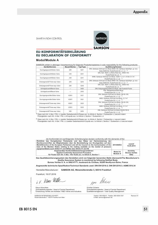
Modul/Module A SAMSON erklärt in alleiniger Verantwortung für folgende Produkte/explaines in sole resposibility for the following products:
Geräte/Devices Bauart/Series Typ/Type Ausführung/Version
Durchgangsventil/Globe Valve 240 3241 DIN, Gehäuse GG/Cast iron-Body DN65-125, Gehäuse GGG/Sph. gr. iron-
Body DN50-80, Fluide/Fluids G2, L1, L2 1)
Durchgangsventil/Globe Valve 240 3241 DIN, Geh. Stahl u.a./Body Steel etc., DN40-100,
Fluide/Fluids G2, L2 2)
Durchgangsventil/Globe Valve 240 3241 ANSI, Gehäuse GG/Cast iron-Body, Cl250 1 ½“-2“, Cl125 2 ½“-4“,
Fluide/Fluids G2, L1, L2 1)
Dreiwegeventil/Three-way Valve 240 3244 DIN, Gehäuse GG/Cast iron-Body DN65-125, Gehäuse GGG/Sph. gr. iron-
Body DN50-80, Fluide/Fluids G2, L1, L2 1)
Dreiwegeventil/Three-way Valve 240 3244 DIN, Geh. Stahl u.a./Body Steel etc., DN40-100,
Fluide/Fluids G2, L2 2)
Schrägsitzventil/Bevel-Valve --- 3353 DIN, Rotgussgehäuse/Bronce-Body, alle Fluide/all Fluids
Schrägsitzventil/Bevel-Valve --- 3353 DIN, Stahlgehäuse/Steel-Body,
Fluide/Fluids G2, L1, L2 1)
Durchgangsventile/Globe Valve V2001 3321 DIN, Gehäuse GG/Cast iron-Body, DN 65-100,
Fluide/Fluids G2, L1, L2 1)
Durchgangsventile/Globe Valve V2001 3321 ANSI, Gehäuse GG/Cast iron-Body, 2 ½“-4“
Fluide/Fluids G2, L1, L2 1)
Dreiwegeventil/Three-way Valve V2001 3323 DIN, Gehäuse GG/Cast iron-Body, DN 65-100,
Fluide/Fluids G2, L1, L2 1)
Dreiwegeventil/Three-way Valve V2001 3323 ANSI, Gehäuse GG/Cast iron-Body, 2 ½“-4“
Fluide/Fluids G2, L1, L2 1)
Dreiwegeventil/Three-way Valve 250 3253 DIN, Gehäuse GG/Cast iron-Body DN200 PN10,
Fluide/Fluids G2, L1, L2 1)1) Gase nach Art. 4 Abs.1 Pkt. c.i zweiter Gedankenstrich//Gases acc. to Article 4, Section 1 Subsection c.i second indent
Flüssigkeiten nach Art. 4 Abs.1 Pkt. c.ii//Liquids acc. to Article 4, Section 1 Subsection c.ii 2) Gase nach Art. 4 Abs.1 Pkt. c.i zweiter Gedankenstrich//Gases acc. to Article 4, Section 1 Subsection c.i second indent
Flüssigkeiten nach Art. 4 Abs.1 Pkt. c.ii zweiter Gedankenstrich//Liquids acc. to Article 4, Section 1 Subsection c.ii second indent
die Konformität mit nachfolgender Anforderung/we declare conformity with the demands of the: Richtlinie des Europäischen Parlaments und des Rates zur Harmonisierung der Rechtsvorschriften der Mitgliedstaaten über die Bereitstellung von Druckgeräten auf dem Markt/Directive of the European Parliament and oft the Council on the harmonisation of the laws of the Member States relating to the making available on the market of pressure equipmentSiehe auch Artikel 41 und 48/See also Article 41 and 48
2014/68/EU vom/of 15.05.2014
Angewandtes Konformitätsbewertungsverfahren/Applied Conformity Assessment Procedure
für Fluide nach Art. 4 Abs. 1/for fluids acc. to Article 4, Section 1 Modul A/ Module A
durch/byBureau Veritas
0062
Das Qualitätssicherungssystem des Herstellers wird von folgender benannten Stelle überwacht/The Manufacturer’s Quality Assurance System is monitored by following Notified Body:
Bureau Veritas S. A. nr 0062 67/71, boulevard du Château, 92200 Neuilly-sur-Seine, France
Angewandte technische Spezifikation/Technical Standards used: DIN EN12516-2; DIN EN12516-3; ASME B16.34
Hersteller/Manufacturer: SAMSON AG, Weismüllerstraße 3, 60314 Frankfurt
Frankfurt, 19.07.2016
Klaus Hörschken Zentralabteilungsleiter / Head of Central Department Entwicklung Ventile und Antriebe / R&D Valves and Actuators
Günther Scherer Zentralabteilungsleiter / Head of Central Department Qualitätsmanagement / Total Quality Management

52 EB 8015 EN
Appendix
SAMSON AKTIENGESELLSCHAFT Weismüllerstraße 3 60314 Frankfurt am Main
Telefon: 069 4009-0 · Telefax: 069 4009-1507 E-Mail: [email protected]
Revison 01
ce_m
odul
_d_d
e_en
_rev
01.d
ocx
Modul/Module D / N° CE-PED-D-SAM 001-13-DEU SAMSON erklärt in alleiniger Verantwortung für folgende Produkte/explaines in sole resposibility for the following products:
Geräte/Devices Bauart/Series Typ/Type Ausführung/VersionStellgerät für Heißwasser und Dampf
mit Sicherheitsfunktion/Safety Accessories for Hot Water and Steam
3374 (2000 N) mit Typ/with Type No. 2811, 2814, 2823, 3321, 3241, 3267 Zertifikat-Nr./Certificate No.: 01 202 931-B-11-0017
Sicherheitsabsperreinrichtung für Feuerungsanlagen/
Safety Accessories for Firing Plants
240 3241 3241-4362, Zertifikat-Nr./Certificate No.: 01 202 931-B-11-0018
240 3241 3241-4364, Zertifikat-Nr./Certificate No.: 01 202 931-B-11-0019
Stellgerät für Heißwasser und Dampf mit Sicherheitsfunktion/
Safety Accessories for Hot Water and Steam
240 3241 mit/with 3271, Zertifikat-Nr./Certificate No.: 01 202 931-B-10-0006
240, 3267 3241, 3267 mit/with 3271 und/and 3277, 240cm² Zertifikat-Nr./Certificate No.: 01 202 931-B-10-0007
240, 3267 3241, 3267 mit/with 3271 und/and 3277, 350cm² Zertifikat-Nr./Certificate No.: 01 202 931-B-10-0008
240 3241auch druckentlastet/also pressure relieved
mit/with 3271 und/and 3277 Zertifikat-Nr./Certificate No.: 01 202 931-B-10-0009
3274 (1800 N) mit/with 3241, 2423, 2823, 3267 Zertifikat-Nr./Certificate No.: 01 202 931-B-10-0027
3274 (3000 N) mit/with 3241, 3214, 2814 Zertifikat-Nr./Certificate No.: 01 202 931-B-10-0028
Stellgerät für Wasser und Dampf mit Sicherheitsfunktion/
Safety Accessories for Water and Steam
3222, 3213, 2488, 2489, 2487, 2491, 2494, 2495, 2423, 3214
2770 mit/with 3267, 2814, 2823, 2710, 2730 Zertifikat-Nr./Certificate No.: 01 202 931-B-09-0008
Sicherheitsabsperreinrichtung für Gasbrenner und Gasgeräte/Safety
Accessories for Gas-burners and Gas-Equipment
240 3241 3241-0261 bis/to 3241-0275 Zertifikat-Nr./Certificate No.: 01 202 931-B-02-0017
Stellgerät zur Leckgasableitung für Gasbrenner und Gasgeräte/Control
Valve for draining for Gas-burners and Gas-equipm.
240 3241 3241-4321 Zertifikat-Nr./Certificate No.: 01 202 931-B-02-0018
die Konformität mit nachfolgender Anforderung/we declare conformity with the demands of the: Richtlinie des Europäischen Parlaments und des Rates zur Harmonisierung der Rechtsvorschriften der Mitgliedstaaten über die Bereitstellung von Druckgeräten auf dem Markt/Directive of the European Parliament and oft the Council on the harmonisation of the laws of the Member States relating to the making available on the market of pressure equipmentSiehe auch Artikel 41 und 48/See also Article 41 and 48
2014/68/EU vom/of 15.05.2014
Angewandtes Konformitätsbewertungsverfahren/Applied Conformity Assessment Procedure
für Fluide nach Art. 4 Abs. 1/for fluids acc. to Article 4, Section 1 Modul D/ Module D
durch/byBureau Veritas
0062
Das Qualitätssicherungssystem des Herstellers wird von folgender benannten Stelle überwacht/The Manufacturer’s Quality Assurance System is monitored by following Notified Body:
Bureau Veritas S. A. nr 0062 67/71, boulevard du Château, 92200 Neuilly-sur-Seine, France
Angewandte technische Spezifikation/Technical Standards used: DIN EN12516-2; DIN EN12516-3; ASME B16.34
Hersteller/Manufacturer: SAMSON AG, Weismüllerstraße 3, 60314 Frankfurt
Frankfurt, 19.07.2016
Klaus Hörschken Zentralabteilungsleiter / Head of Central Department Entwicklung Ventile und Antriebe / R&D Valves and Actuators
Günther Scherer Zentralabteilungsleiter / Head of Central Department Qualitätsmanagement / Total Quality Management

EB 8015 EN 53
Appendix
SAMSON AKTIENGESELLSCHAFT Weismüllerstraße 3 60314 Frankfurt am Main
Telefon: 069 4009-0 · Telefax: 069 4009-1507 E-Mail: [email protected]
Revison 01
ce_m
odul
_h_d
e_en
_rev
01.d
ocx
Modul/Module H / N° CE-PED-H-SAM 001-13-DEU SAMSON erklärt in alleiniger Verantwortung für folgende Produkte/explaines in sole resposibility for the following products:
Geräte/Devices Bauart/Series Typ/Type Ausführung/Version
Durchgangsventil/Globe Valve 240 3241 DIN, Gehäuse GG/Cast iron-Body ab/from DN150, Gehäuse GGG/Sph. gr.
iron-Body ab/from DN100, Fluide/Fluids G2, L1, L2 1)
DIN/ANSI, Geh. Stahl u.a./Body Steel etc., alle Fluide/all Fluids
Dreiwegeventil/Three-way Valve 240 3244 DIN, Gehäuse GG ab DN150/Cast iron-Body from DN150; Gehäuse GGG ab
DN100/Sph. gr. iron-Body from DN100, Fluide/Fluids G2, L1, L2 1)
DIN/ANSI, Geh. Stahl u.a./Body Steel etc., alle Fluide/all Fluids Tieftemperaturventil/Cryogenic Valve 240 3248 DIN/ANSI, alle Fluide/all Fluids
Durchgangsventil/Globe Valve 250 3251 DIN/ANSI, alle Fluide/all Fluids Dreiwegeventil/Three-way Valve 250 3253 DIN/ANSI, Geh. Stahl u.a./Body Steel etc., alle Fluide/all Fluids Durchgangsventil/Globe Valve 250 3254 DIN/ANSI, alle Fluide/all Fluids
Eckventil/Angle Valve 250 3256 DIN/ANSI, alle Fluide/all Fluids Split-Body-Ventil/Split-Body-Valve 250 3258 DIN, alle Fluide/all Fluids
IG-Eckventil/IG-Angle Valve 250 3259 DIN, alle Fluide/all Fluids
Dampfumformventil/ Steam-converting Valve 280
3281 DIN/ANSI, alle Fluide/all Fluids 3284 DIN/ANSI, alle Fluide/all Fluids 3286 DIN/ANSI, alle Fluide/all Fluids 3288 DIN, alle Fluide/all Fluids
Durchgangsventile/Globe Valve V2001 3321 DIN, Geh. Stahl u.a./Body Steel etc., alle Fluide/all Fluids ANSI, alle Fluide/all Fluids
Dreiwegeventil/Three-way Valve V2001 3323 DIN, Geh. Stahl u.a./Body Steel etc., alle Fluide/all Fluids ANSI, alle Fluide/all Fluids
Schrägsitzventil/Bevel-Valve --- 3353 DIN, Geh. Stahl/Body Steel, alle Fluide/all Fluids
Drosselschalldämpfer/Silencer 3381
3381-1 DIN/ANSI, alle Fluide/all Fluids; Einzeldrosselscheibe mit Anschweißende/ Single attenuation plate with welding end
3381-3 DIN/ANSI, alle Fluide/all Fluids
3381-4 DIN/ANSI, alle Fluide/all Fluids; Einzeldrosselscheibe mehrstufig mit Anschweißende/Single attenuation plate multi-stage with welding end
Durchgangsventil/Globe Valve 240 3241 ANSI, Gehäuse GG Cl125 ab 5"/Cast iron-Body Cl125 from 5", Fluide/Fluids G2, L1, L2 1)
Tieftemperaturventil/ Cryogenic Valve 240 3246 DIN/ANSI, alle Fluide/all Fluids
Dreiwegeventil/Three-way Valve 250 3253 DIN, Gehäuse GG ab DN200 PN16/Cast iron-Body from DN200 PN16, Fluide/Fluids G2, L1, L2 1)
Durchgangsventil/Globe Valve 290 3291 ANSI, alle Fluide/all Fluids Eckventil/Angle Valve 290 3296 ANSI, alle Fluide/all Fluids
Durchgangsventil/Globe Valve 590 3591 ANSI, alle Fluide/all Fluids Eckventil/Angle Valve 590 3596 ANSI, alle Fluide/all Fluids
1) Gase nach Art. 4 Abs.1 Pkt. c.i zweiter Gedankenstrich//Gases acc. to Article 4, Section 1 Subsection c.i second indent Flüssigkeiten nach Art. 4 Abs.1 Pkt. c.ii//Liquids acc. to Article 4, Section 1 Subsection c.ii
die Konformität mit nachfolgender Anforderung/we declare conformity with the demands of the: Richtlinie des Europäischen Parlaments und des Rates zur Harmonisierung der Rechtsvorschriften der Mitgliedstaaten über die Bereitstellung von Druckgeräten auf dem Markt/Directive of the European Parliament and oft the Council on the harmonisation of the laws of the Member States relating to the making available on the market of pressure equipmentSiehe auch Artikel 41 und 48/See also Article 41 and 48
2014/68/EU vom/of 15.05.2014
Angewandtes Konformitätsbewertungsverfahren/Applied Conformity Assessment Procedure
für Fluide nach Art. 4 Abs. 1/for fluids acc. to Article 4, Section 1 Modul H/ Module H
durch/byBureau Veritas
0062
Das Qualitätssicherungssystem des Herstellers wird von folgender benannten Stelle überwacht/The Manufacturer’s Quality Assurance System is monitored by following Notified Body:
Bureau Veritas S. A. nr 0062 67/71, boulevard du Château, 92200 Neuilly-sur-Seine, France
Angewandte technische Spezifikation/Technical Standards used: DIN EN12516-2; DIN EN12516-3; ASME B16.34
Hersteller/Manufacturer: SAMSON AG, Weismüllerstraße 3, 60314 Frankfurt
Frankfurt, 19.07.2016
Klaus Hörschken Zentralabteilungsleiter / Head of Central Department Entwicklung Ventile und Antriebe / R&D Valves and Actuators
Günther Scherer Zentralabteilungsleiter / Head of Central Department Qualitätsmanagement / Total Quality Management

54 EB 8015 EN
Appendix
SAMSON AKTIENGESELLSCHAFT Weismüllerstraße 3 60314 Frankfurt am Main
Telefon: 069 4009-0 · Telefax: 069 4009-1507 E-Mail: [email protected]
Revison 01
Modul/Module H / N° CE-PED-H-SAM 001-13-DEU SAMSON erklärt in alleiniger Verantwortung für folgende Typen / explaines in sole resposibility for the following products:
Ventile für elektrische Stellgeräte / Globe and three-way valves equipped with electric actuators
Typ / Type 3213, 3222 (Erz.-Nr. / Model No.. 2710); 3323, 3535 (2803); 3213, 3531 (2811); 3214 (2814); 2423E (2823); 241 (3241); 244 (3244); 267 (3267);
die Konformität mit nachfolgender Anforderung / the conformity with the following requirement.
Richtlinie des Europäischen Parlaments und des Rates zur Harmonisierung der Rechtsvorschriften der Mitgliedstaaten über die Bereitstellung von Druckgeräten auf dem Markt (siehe auch Artikel 41 und 48).
2014/68/EU vom 15.05.2014
Directive of the European Parliament and oft the Council on the harmonisation of the laws of the Member States relating of the making available on the market of pressure equipment (see also Article 41 and 48).
2014/68/EU of 15.05.2014
Angewandtes Konformitätsbewertungsverfahren für Fluide nach Art. 4 Abs.1 Pkt. c.i erster Gedankenstrich.
Modul siehe Tabelle
durch certified by
Bureau Veritas S. A. (0062)
Conformity assessment procedure applied for fluids according to Article 4, Section 1, Subsection c.i, first indent.
For type of mo-dule, see table
Nenndruck Nominal pressure
DNNPS
15½
20¾
251
321¼
401½
502
65-
803
1004
125-
1506
2008
25010
30012
40016
PN 25 ohne (1) A (2) H - PN 40 ohne (1) H - Class 150 ohne (1) A (2) H - Class 300 ohne (1) H -
(1) Das auf dem Stellgerät aufgebrachte CE-Zeichen hat keine Gültigkeit im Sinne der Druckgeräterichtlinie The CE marking affixed to the control device does not refer to the Pressure Equipment Directive.
(2) Das auf dem Stellgerät aufgebrachte CE-Zeichen gilt ohne Bezeichnung der Notifizierten Stelle (Kennr. 0062) The CE marking affixed to the control device is valid, but does not refer to the notified body (ID No. is invalid).
Geräte, denen laut Tabelle das Konformitätsbewertungsverfahren Modul H zugrunde liegt, beziehen sich auf die „Zulassungsbescheinigung eines Qualitätssicherungssystems“ ausgestellt durch die Notifizierte Stelle. The module H conformity assessment procedure applied to the valves according to the table is based on the “Certificate of Quality System Approval” issued by the notified body. Dem Entwurf zu Grunde gelegt sind Verfahren aus: / The design is based on the methods of: DIN EN 12516-2, DIN EN 12516-3 bzw. / respectively ASME B16.24, ASME B16.34, ASME B16.42 Das Qualitätssicherungssystem des Herstellers wird von folgender benannter Stelle überwacht The Manufactur`s Quality Assurance System is monitored by following Notifed Body
Bureau Veritas S.A. nr 0062 67/71, boulevard du Chateau, 92200 Neuilly-sur-Seine, France Hersteller / Manufacturer: SAMSON AG / Weismüllerstraße 3 / 60314 Frankfurt
Frankfurt am Main, den 19.07.2016
Klaus Hörschken Günther Scherer Zentralabteilungsleiter / Head of Central Department Zentralabteilungsleiter / Head of Central Department Entwicklung Ventile und Antriebe / Development Valves and Actuators Total Quality Management / Total Quality Management
ce_m
odul
_h_u
nd_a
_de_
en_r
ev01
.doc
x
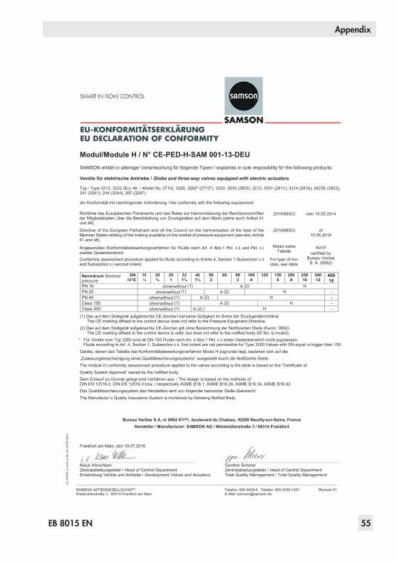
EB 8015 EN 55
Appendix
SAMSON AKTIENGESELLSCHAFT Weismüllerstraße 3 60314 Frankfurt am Main
Telefon: 069 4009-0 · Telefax: 069 4009-1507 E-Mail: [email protected]
Revison 01
Modul/Module H / N° CE-PED-H-SAM 001-13-DEU SAMSON erklärt in alleiniger Verantwortung für folgende Typen / explaines in sole resposibility for the following products:
Ventile für elektrische Antriebe / Globe and three-way valves equipped with electric actuators
Typ / Type 3213, 3222 (Erz.-Nr. / Model No. 2710); 3226, 3260* (2713*); 3323, 3535 (2803); 3213, 3531 (2811); 3214 (2814); 2423E (2823); 241 (3241); 244 (3244); 267 (3267)
die Konformität mit nachfolgender Anforderung / the conformity with the following requirement.
Richtlinie des Europäischen Parlaments und des Rates zur Harmonisierung der Rechtsvorschriften der Mitgliedstaaten über die Bereitstellung von Druckgeräten auf dem Markt (siehe auch Artikel 41 und 48).
2014/68/EU vom 15.05.2014
Directive of the European Parliament and oft the Council on the harmonisation of the laws of the Member States relating of the making available on the market of pressure equipment (see also Article 41 and 48).
2014/68/EU of 15.05.2014
Angewandtes Konformitätsbewertungsverfahren für Fluide nach Art. 4 Abs.1 Pkt. c.ii und Pkt. c.i zweiter Gedankenstrich.
Modul siehe Tabelle
durch certified by
Bureau Veritas S. A. (0062)
Conformity assessment procedure applied for fluids according to Article 4, Section 1 Subsection c.ii and Subsection c.i second indent.
For type of mo-dule, see table
Nenndruck Nominal pressure
DNNPS
15½
20¾
251
321¼
401½
502
65 803
1004
125 1506
2008
25010
30012
40016
PN 16 ohne/without (1) A (2) H PN 25 ohne/without (1) A (2) H - PN 40 ohne/without (1) A (2) H - Class 150 ohne/without (1) A (2) H - Class 300 ohne/without (1) A (2) H -
(1) Das auf dem Stellgerät aufgebrachte CE-Zeichen hat keine Gültigkeit im Sinne der Druckgeräterichtlinie The CE marking affixed to the control device does not refer to the Pressure Equipment Directive.
(2) Das auf dem Stellgerät aufgebrachte CE-Zeichen gilt ohne Bezeichnung der Notifizierten Stelle (Kennr. 0062) The CE marking affixed to the control device is valid, but does not refer to the notified body (ID No. is invalid).
* Für Ventile vom Typ 3260 sind ab DN 150 Fluide nach Art. 4 Abs.1 Pkt. c.ii erster Gedankenstrich nicht zugelassen. Fluids according to Art. 4, Section 1, Subsection c.ii, first indent are not permissible for Type 3260 Valves with DN equal or bigger than 150.
Geräte, denen laut Tabelle das Konformitätsbewertungsverfahren Modul H zugrunde liegt, beziehen sich auf die „Zulassungsbescheinigung eines Qualitätssicherungssystems“ ausgestellt durch die Notifizierte Stelle. The module H conformity assessment procedure applied to the valves according to the table is based on the “Certificate of Quality System Approval” issued by the notified body. Dem Entwurf zu Grunde gelegt sind Verfahren aus: / The design is based on the methods of: DIN EN 12516-2, DIN EN 12516-3 bzw. / respectively ASME B16.1, ASME B16.24, ASME B16.34, ASME B16.42 Das Qualitätssicherungssystem des Herstellers wird von folgender benannter Stelle überwacht The Manufactur`s Quality Assurance System is monitored by following Notifed Body
Bureau Veritas S.A. nr 0062 67/71, boulevard du Chateau, 92200 Neuilly-sur-Seine, France Hersteller / Manufacturer: SAMSON AG / Weismüllerstraße 3 / 60314 Frankfurt
Frankfurt am Main, den 19.07.2016
Klaus Hörschken Günther Scherer Zentralabteilungsleiter / Head of Central Department Zentralabteilungsleiter / Head of Central Department Entwicklung Ventile und Antriebe / Development Valves and Actuators Total Quality Management / Total Quality Management
ce_m
odul
_h_u
nd_a
_de_
en_r
ev01
.doc
x

56 EB 8015 EN
Appendix
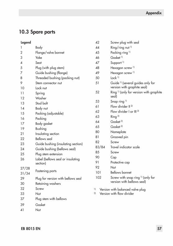
EB 8015 EN 57
Appendix
10.3 Spare parts
Legend1 Body2 Flange/valve bonnet3 Yoke4 Seat5 Plug (with plug stem)7 Guide bushing (flange)8 Threaded bushing (packing nut)9 Stem connector nut10 Lock nut11 Spring12 Washer13 Stud bolt14 Body nut15 Packing (adjustable)16 Packing17 Body gasket19 Bushing21 Insulating section22 Bellows seal23 Guide bushing (insulating section)24 Guide bushing (bellows seal)25 Plug stem extension26 Label (bellows seal or insulating
section)27/28
Fastening parts31/3429 Plug for version with bellows seal30 Retaining washers32 Screw33 Nut37 Plug stem with bellows
39 Gasket41 Nut
42 Screw plug with seal44 Ring/ring nut 1)
45 Packing ring 1)
46 Gasket 1)
47 Support 1)
48 Hexagon screw 1)
49 Hexagon screw 1)
50 Lock 1)
51 Guide 1) (several guides only for version with graphite seal)
52 Ring 1) (only for version with graphite seal)
53 Snap ring 1)
61 Flow divider II 2)
62 Flow divider I or III 2)
63 Ring 2)
64 Gasket 2)
65 Gasket 2)
80 Nameplate81 Grooved pin82 Screw83/84 Travel indicator scale85 Screw90 Cap91 Protective cap92 Nut101 Bellows bonnet102 Screw with snap ring 1) (only for
version with bellows seal)
1) Version with balanced valve plug2) Version with flow divider

DN 15…150NPS ½…6
909
10
1512
1219
168
11
232
7
81
41
373042
81
26
2422
5
1763
62
61
4
80828384
2530 33
14 33
91 911
91 911
13
39
14
14
2123
90910
151216
8
111219
8180
8126
828384
72
5
4851
4753
445245
50
4649
5046
5244
4547
4853
51

DN 200…300NPS 8…12
(DN 250, DN 300)(10", 12")
80 81
92
83
32
8480 81 83 84
8582
3
42
9
108
16
16
12
12
12
19
111219
15
3
37
397101
33
1439222
2114
8175
26
7
242728295
64656362
61
4 13 91191
17
3431
14
2681
92
8582
9108
161219191211
15
5102
4851
4753
445245
50
4649
5046
5244
4547
4853
51

SAMSON AG · MESS- UND REGELTECHNIKWeismüllerstraße 3 · 60314 Frankfurt am Main, GermanyPhone: +49 69 4009-0 · Fax: +49 69 [email protected] · www.samson.de EB 8015 EN 20
16-1
2-08
· En
glish