moving coil galvanometerstaff.um.edu.mt/maurice.apap/epc1201/electrical...multi-range moving-coil...
TRANSCRIPT
Moving Coil Galvanometer
N S
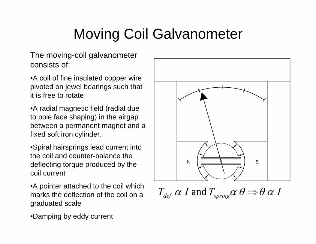
The moving-coil galvanometer consists of:•A coil of fine insulated copper wire pivoted on jewel bearings such that it is free to rotate
•A radial magnetic field (radial due to pole face shaping) in the airgapbetween a permanent magnet and a fixed soft iron cylinder.
•Spiral hairsprings lead current into the coil and counter-balance the deflecting torque produced by the coil current
•A pointer attached to the coil which marks the deflection of the coil on a graduated scale
•Damping by eddy current
ITIT springdef and αθθαα ⇒
Multi-Range Moving-Coil Ammeter
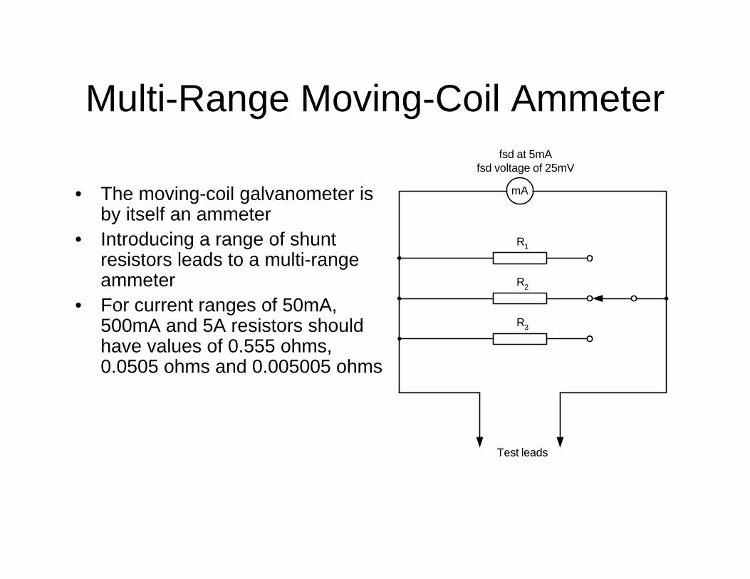
• The moving-coil galvanometer is by itself an ammeter
• Introducing a range of shunt resistors leads to a multi-range ammeter
• For current ranges of 50mA, 500mA and 5A resistors should have values of 0.555 ohms, 0.0505 ohms and 0.005005 ohms
mA
fsd at 5mAfsd voltage of 25mV
R1
R2
R3
Test leads
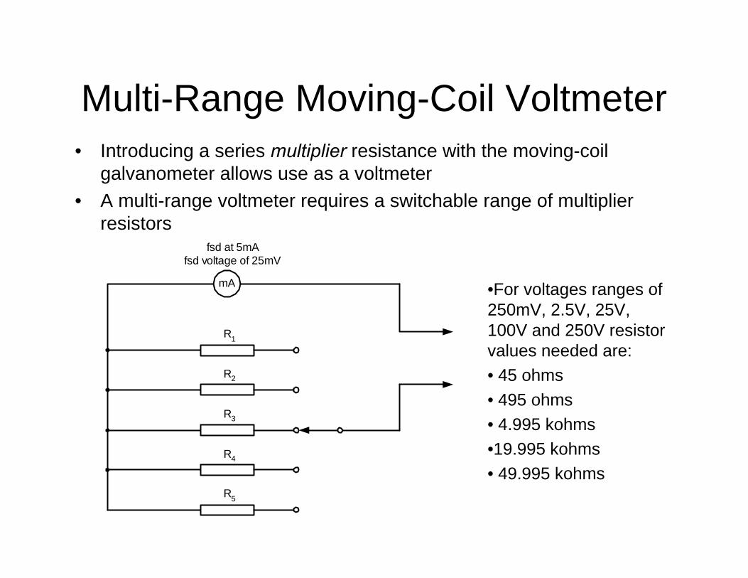
Multi-Range Moving-Coil Voltmeter• Introducing a series multiplier resistance with the moving-coil
galvanometer allows use as a voltmeter• A multi-range voltmeter requires a switchable range of multiplier
resistors
mA
fsd at 5mAfsd voltage of 25mV
R1
R2
R3
R5
R4
•For voltages ranges of 250mV, 2.5V, 25V, 100V and 250V resistor values needed are:• 45 ohms• 495 ohms• 4.995 kohms•19.995 kohms• 49.995 kohms
AC Electrical Instruments
• Rectifier Instruments – these are based on the moving coil meter with torque related to average current. AC rectified to DC to produce non-zero average current
• Instruments where torque is related to average current squared: Moving Iron, Electrodynamic Instruments
• Induction type (ac only): power/energy meters
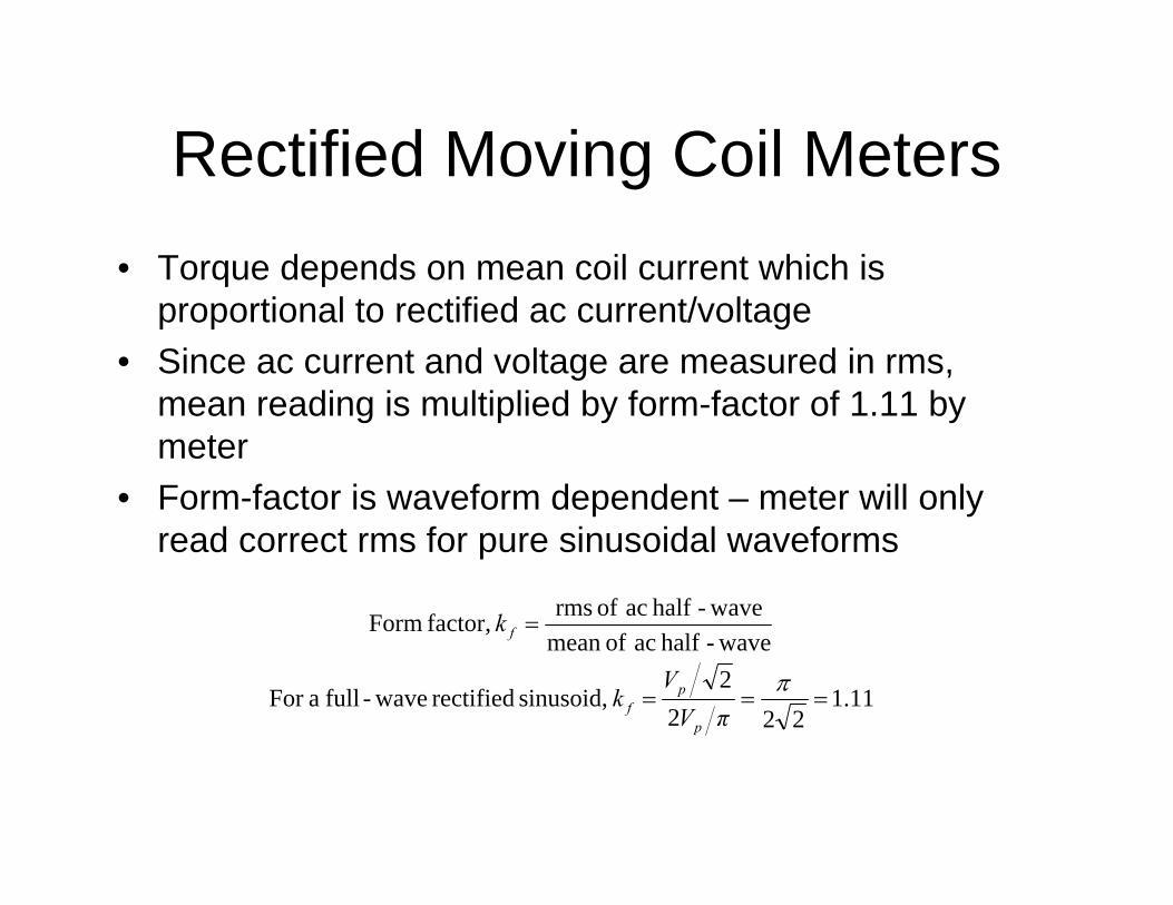
Rectified Moving Coil Meters• Torque depends on mean coil current which is
proportional to rectified ac current/voltage• Since ac current and voltage are measured in rms,
mean reading is multiplied by form-factor of 1.11 by meter
• Form-factor is waveform dependent – meter will only read correct rms for pure sinusoidal waveforms
11.1222
2 sinusoid, rectified wave-full aFor
wave-half ac ofmean wave-half ac of rms factor, Form
===
=
ππV
Vk
k
p
pf
f
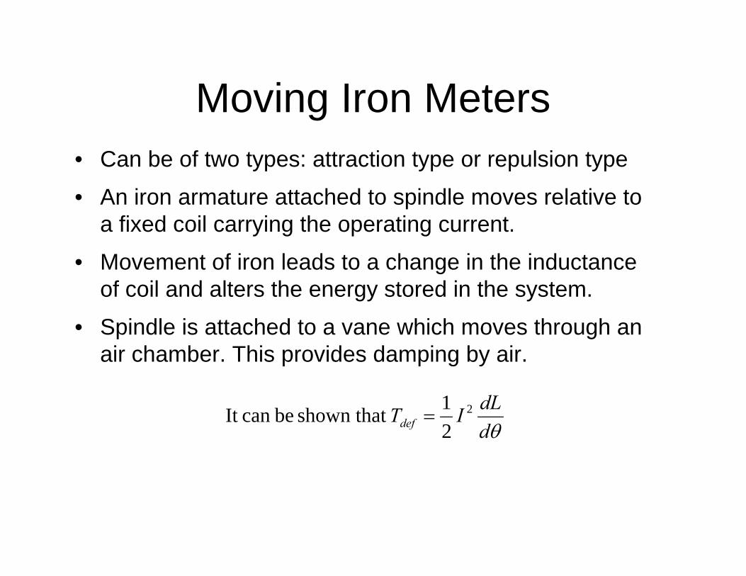
Moving Iron Meters• Can be of two types: attraction type or repulsion type
• An iron armature attached to spindle moves relative to a fixed coil carrying the operating current.
• Movement of iron leads to a change in the inductance of coil and alters the energy stored in the system.
• Spindle is attached to a vane which moves through an air chamber. This provides damping by air.
θddLITdef
2
21 shown that becan It =
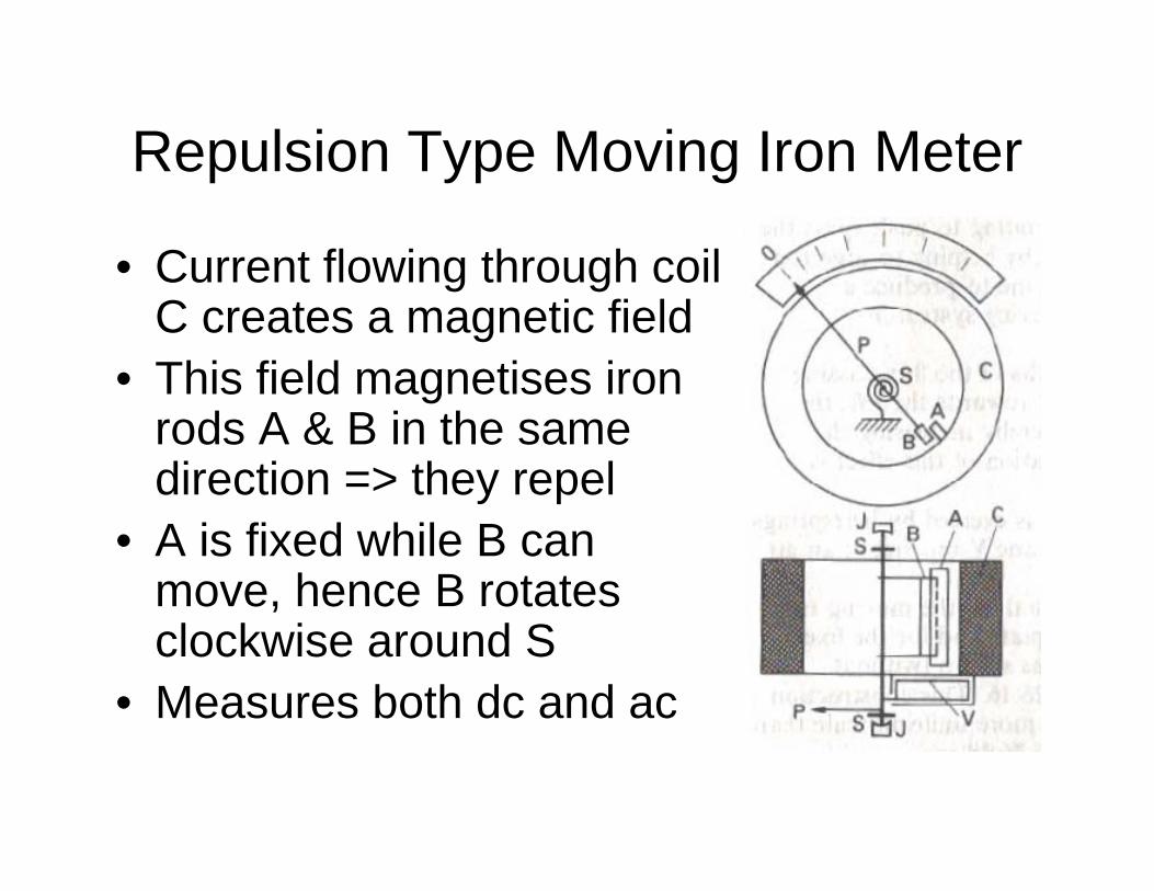
Repulsion Type Moving Iron Meter
• Current flowing through coil C creates a magnetic field
• This field magnetises iron rods A & B in the same direction => they repel
• A is fixed while B can move, hence B rotates clockwise around S
• Measures both dc and ac
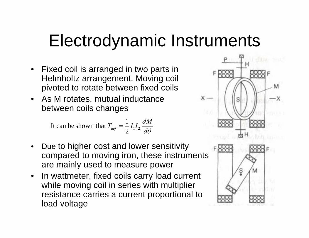
Electrodynamic Instruments• Fixed coil is arranged in two parts in
Helmholtz arrangement. Moving coil pivoted to rotate between fixed coils
• As M rotates, mutual inductance between coils changes
θddMIITdef 212
1 shown that becan It =
• Due to higher cost and lower sensitivity compared to moving iron, these instruments are mainly used to measure power
• In wattmeter, fixed coils carry load current while moving coil in series with multiplier resistance carries a current proportional to load voltage
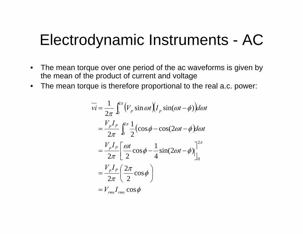
Electrodynamic Instruments - AC• The mean torque over one period of the ac waveforms is given by
the mean of the product of current and voltage• The mean torque is therefore proportional to the real a.c. power:
( )( )
( )
φ
φππ
φωφωπ
ωφωφπ
ωφωωπ
π
π
π
cos
cos2
22
)2sin(41cos
22
2cos(cos21
2
)sin(sin21
2
0
2
0
2
0
rmsrms
Pp
Pp
Pp
pp
IV
IV
ttIV
tdtIV
tdtItVvi
=
⎟⎠⎞
⎜⎝⎛=
⎥⎦⎤
⎢⎣⎡ −−=
−−=
−=
∫
∫
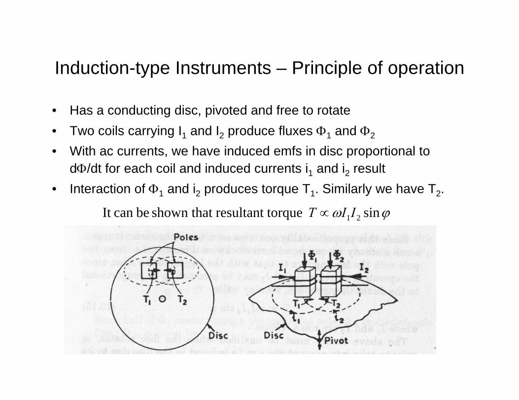
Induction-type Instruments – Principle of operation
• Has a conducting disc, pivoted and free to rotate• Two coils carrying I1 and I2 produce fluxes Φ1 and Φ2
• With ac currents, we have induced emfs in disc proportional to dΦ/dt for each coil and induced currents i1 and i2 result
• Interaction of Φ1 and i2 produces torque T1. Similarly we have T2.
ϕω sin torqueresultant shown that becan It 21IIT ∝
Induction Wattmeter / Energy Meter• One coil designed for low resistance and low inductance to carry
line current• Second coil is designed to be highly reactive as the flux needs to lag
supply voltage by 90° for correct operation. (In practice, this is achieved by introducing a secondary closed winding)
• Deflecting torque is proportional to IVsin(90-φ), i.e. IVcos φ• In the induction wattmeter, disc rotation is limited by linear control
spring gives deflection proportional to real power• In the energy meter, the disc is allowed to rotate continuously. In this
case, the control torque is provided by eddy currents due to a braking magnet acting on the rotating conducting disc. The disc drives a gear train which controls a set of indicating dials. Disc speed is proportional to power, therefore number of rotations represents energy consumed.
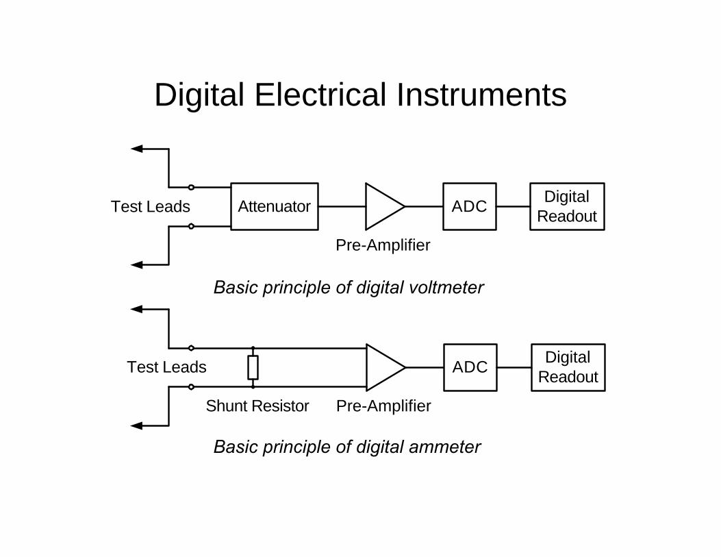
Digital Electrical Instruments
Attenuator ADC DigitalReadout
Pre-Amplifier
Test Leads
Basic principle of digital voltmeter
Basic principle of digital ammeter
ADC DigitalReadout
Pre-Amplifier
Test Leads
Shunt Resistor
Digital Electrical Instruments - 2
At the basis of the digital instrument we have the Analogue-to-Digital Converter (ADC) that converts dc to digital output:
• Analogue processing instruments perform all necessary functions using analogue circuits: averaging, rms-to-dc, analogue multiplication for a wattmeter, etc. The dc output from such circuits is input to the ADC which then provides the digital reading for the display.
• Digital Signal Processing instruments sample the input quantities (ac inputs are level-shifted to obtain dc inputs). The dc representation of instantaneous input quantities are sampled by the ADC at a high sampling frequency and the digital representation of the samples are then processed digitally according to the required function: averaging, true-rms, multiplication and averaging for power, etc.