mp2600iec hardware manual - logic control · • 1 external encoder (quadrature, ... magnetic...
TRANSCRIPT

™
MP2600iec Hardware Manual


Table of Contents
Table of Contents1 Introduction
1.1 MP2600iec Features - - - - - - - - - - - - - - - - - - - - - - - - 3
1.2 MP2600iec Appearance- - - - - - - - - - - - - - - - - - - - - - 4
1.3 Model Number Reference - - - - - - - - - - - - - - - - - - - - 5
2 Specifications 2.1 General Specifications - - - - - - - - - - - - - - - - - - - - - - - 7
2.2 MP2600iec Hardware Specifications - - - - - - - - - - - - - 8
3 Mechanical Installation 3.1 Mounting Information- - - - - - - - - - - - - - - - - - - - - - - - 9
3.2 Installation Standards - - - - - - - - - - - - - - - - - - - - - - 10
3.3 Dimensions- - - - - - - - - - - - - - - - - - - - - - - - - - - - - - 11
4 Inputs/Outputs 4.1 CN13 Connection Diagram - - - - - - - - - - - - - - - - - - 13
4.2 CN13 Connection Description - - - - - - - - - - - - - - - - 14
4.3 External Encoder Interface - - - - - - - - - - - - - - - - - - 15
4.4 Controller Digital I/O - - - - - - - - - - - - - - - - - - - - - - - 16
4.5 Sigma-5 I/O - - - - - - - - - - - - - - - - - - - - - - - - - - - - - 18
4.6 Analog I/O - - - - - - - - - - - - - - - - - - - - - - - - - - - - - - 19
5 DIP Switches 5.1 Switch Settings - - - - - - - - - - - - - - - - - - - - - - - - - - - 21
6 LED Outputs - - - - - - - - - - - - - - - - - - - - - - - - - - - - - - - 23
7 Battery 7.1 Battery Installation- - - - - - - - - - - - - - - - - - - - - - - - - 25
1
Table of Contents
8 Ethernet 8.1 Connectivity Information- - - - - - - - - - - - - - - - - - - - - 27
8.2 Ethernet Connector Details- - - - - - - - - - - - - - - - - - - 27
8.3 Ethernet Cable - - - - - - - - - - - - - - - - - - - - - - - - - - - 28
8.4 Ethernet Connection Examples- - - - - - - - - - - - - - - - 28
9 Cable Diagrams 9.1 CBK-U-MP2B-xx (Terminal Block-Controller) - - - - - - 31
9.2 CFC-U-MP2B-xx (Flying Lead-Controller) - - - - - - - - 32
9.3 SBK-U-VBA-xx (Terminal Block-Servo Amp) - - - - - - 33
9.4 JZSP-CSI02-x-E (Flying Lead-Servo Amp) - - - - - - - 34
10 Firmware Upgrade Procedure - - - - - - - - - - - - - - - - - 35
11 EMC Installation Conditions - - - - - - - - - - - - - - - - - - 37
2
1.1 MP2600iec Features
1 Introduction
1.1 MP2600iec Features
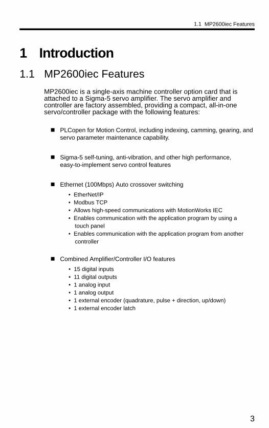
MP2600iec is a single-axis machine controller option card that is attached to a Sigma-5 servo amplifier. The servo amplifier and controller are factory assembled, providing a compact, all-in-one servo/controller package with the following features:
PLCopen for Motion Control, including indexing, camming, gearing, and servo parameter maintenance capability.
Sigma-5 self-tuning, anti-vibration, and other high performance, easy-to-implement servo control features
Ethernet (100Mbps) Auto crossover switching
• EtherNet/IP• Modbus TCP• Allows high-speed communications with MotionWorks IEC• Enables communication with the application program by using a
touch panel• Enables communication with the application program from another
controller
Combined Amplifier/Controller I/O features
• 15 digital inputs• 11 digital outputs• 1 analog input• 1 analog output• 1 external encoder (quadrature, pulse + direction, up/down)• 1 external encoder latch
3

1.2 MP2600iec Appearance
1.2 MP2600iec Appearance
The following figure shows the external appearance of the MP2600iec controller (Note: The servo amplifier is not shown).
LED (10 points)
Ethernet Port A
Ethernet Port B
DIP Switch (6 points)
CN13 PortAnalog I/O, Digital I/O
External Encoder (incremental)
3.6V Lithium Battery(preserves retained variables,
absolute encoder offset, and real-time clock data)
4

1.3 Model Number Reference
1.3.1 Model Number Designation
1.3 Model Number Reference
1.3.1 Model Number Designation
R70 A E 1 A 000 00 0 300Series SGDV SERVOPACK
SGDV
Current
Interface Options
Design Revision OrderA, B…
Voltage
Code Specifications
E Communication Reference
Code Specifications
F 100 VAC
A 200 VAC
D 400 VAC
Options (hardware)Code Specifications
000 Base-mounted (standard)
Options (software)Code Specifications
00 standard
Options (parameter)Code Specifications
0 standard
Option ModuleCode Specifications
300 MP2600iec 1.5 Axis Machine Controller ModuleVoltage Code Applicable Servomotor
Max. Capacity kW
100V
R70 0.05R90 0.12R1 0.22R8 0.4
200V
R70* 0.05R90* 0.11R6* 0.22R8* 0.43R8 0.55R5* 0.757R6 1.0120 ♣ 1.5180 2.0200 3.0330 5.0470 6.0550 7.5590 11780 15
400V
1R9 0.53R5 1.05R4 1.58R4 2.0120 3.0170 5.0210 6.0260 7.5280 11370 15
Motor Type
Code Specifications1 Rotary Servomotors
5** Linear Servomotors
** Under Development
* These amplifiers can be powered with single or three-phase.♣ SGDV-120A¡¡A008000¡¡¡, a special version of the 1.5kW amplifier can be used for single-phase operation.
5
1.3 Model Number Reference
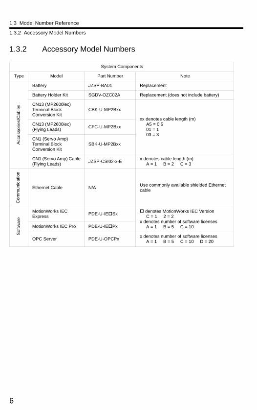
1.3.2 Accessory Model Numbers
1.3.2 Accessory Model Numbers
System Components
Type Model Part Number Note
Acc
esso
ries/
Cab
les
Battery JZSP-BA01 Replacement
Battery Holder Kit SGDV-OZC02A Replacement (does not include battery)
CN13 (MP2600iec) Terminal Block Conversion Kit
CBK-U-MP2Bxx
xx denotes cable length (m) A5 = 0.5 01 = 1 03 = 3
CN13 (MP2600iec) (Flying Leads)
CFC-U-MP2Bxx
CN1 (Servo Amp) Terminal Block Conversion Kit
SBK-U-MP2Bxx
CN1 (Servo Amp) Cable (Flying Leads)
JZSP-CSI02-x-Ex denotes cable length (m) A = 1 B = 2 C = 3
Co
mm
un
icat
ion
Ethernet Cable N/AUse commonly available shielded Ethernet cable
Sof
twar
e
MotionWorks IEC Express
PDE-U-IESx denotes MotionWorks IEC Version C = 1 2 = 2x denotes number of software licenses A = 1 B = 5 C = 10MotionWorks IEC Pro PDE-U-IEPx
OPC Server PDE-U-OPCPxx denotes number of software licenses A = 1 B = 5 C = 10 D = 20
6
2.1 General Specifications
2 Specifications
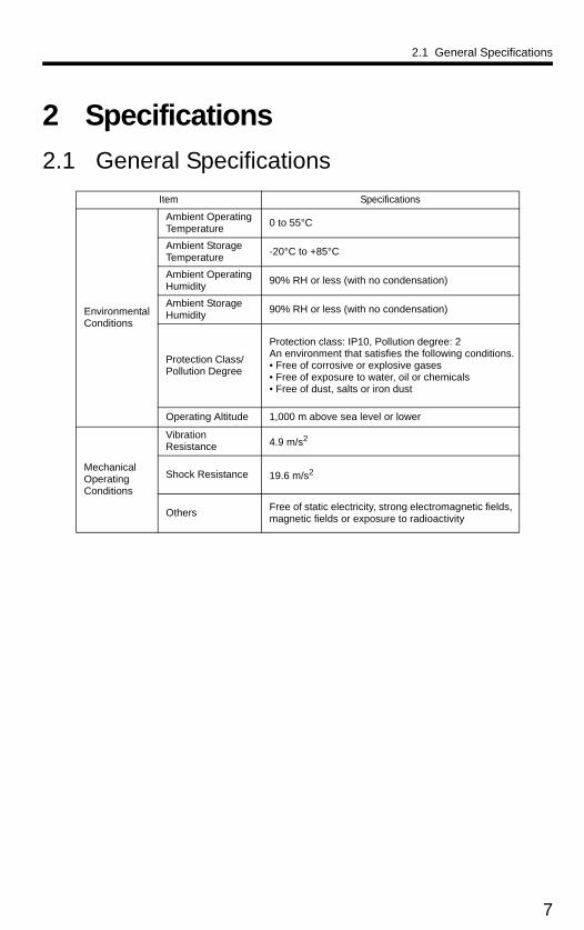
2.1 General Specifications
Item Specifications
Environmental Conditions
Ambient Operating Temperature
0 to 55°C
Ambient Storage Temperature
-20°C to +85°C
Ambient Operating Humidity
90% RH or less (with no condensation)
Ambient Storage Humidity
90% RH or less (with no condensation)
Protection Class/Pollution Degree
Protection class: IP10, Pollution degree: 2An environment that satisfies the following conditions.• Free of corrosive or explosive gases• Free of exposure to water, oil or chemicals• Free of dust, salts or iron dust
Operating Altitude 1,000 m above sea level or lower
Mechanical Operating Conditions
Vibration Resistance 4.9 m/s2
Shock Resistance 19.6 m/s2
OthersFree of static electricity, strong electromagnetic fields, magnetic fields or exposure to radioactivity
7

2.2 MP2600iec Hardware Specifications
2.2 MP2600iec Hardware Specifications
* Allocated I/O can also be used as programmable I/O if the output functions are disabled.
Item Specification
CPU 200 MHz, 32 bit, ARM 9
Memory
SDRAM 32 MB
SRAM 512 kB with battery backup
Flash 4 MB flash. Code and parameter storage.
Operator interface
LED10 LEDs (red and green - operating mode, communication and error status)
User Configuration6x DIP switch (operating mode and communication configuration)
User I/O
Controller Side (CN13)
Network 2x 100baseTX Ethernet
Digital input 8 programmable inputs
Digital output 8 programmable outputs
Analog input 1 ch., +/- 10V, 16 bit
Analog output 1 ch., +/- 10V, 16 bit
Pulse CounterRS-422-compatible pulse counter input (quadrature, pulse and direction, and up/down counter modes) with 5, 12, or 24V position latch input
Servo-Side (CN1)
Sequence Input
Allocated*
Number of Inputs: 7
Functions: The signal allocation and positive/negative logic can be modified. Forward run prohibited (P-OT), reverse run prohibited (N-OT), forward torque limit (/P-CL), reverse torque limit (/N-CL), general-purpose input signal (/SI0 to /SI6)
Sequence Output
Fixed Servo Alarm (ALM)
Allocated*
Number of Outputs: 3
Functions: The signal allocation and positive/negative logic can be modified. Positioning completion (/COIN), speed coincidence detection(/V-CMP), servomotor rotation detection (/TGON), servo ready (/S-RDY), torque limit detection (/CLT), speed limit detection (VLT), brake (/BK), warning (/WARN), near (/NEAR)
Network capability
OPC (Client and Server required)
EtherNet/IP
Modbus/TCP
Programming standards IEC61131-3/PLCopen
Diagnostic and configuration interface Web interface
Motion control performance1 controlled axis and one external position input at a trajectory update rate of 1 kHz
Servo-Side Safety Functions
Input/HWBB1, /HWBB2: Baseblock signal for power module
OutputEDM1: Status monitor (fixed output) of built-in safety circuit
8

3.1 Mounting Information
3 Mechanical Installation
3.1 Mounting InformationThe MP2600iec controller is pre-assembled to the Sigma-5 servo amplifier by the factory.
9
3.2 Installation Standards
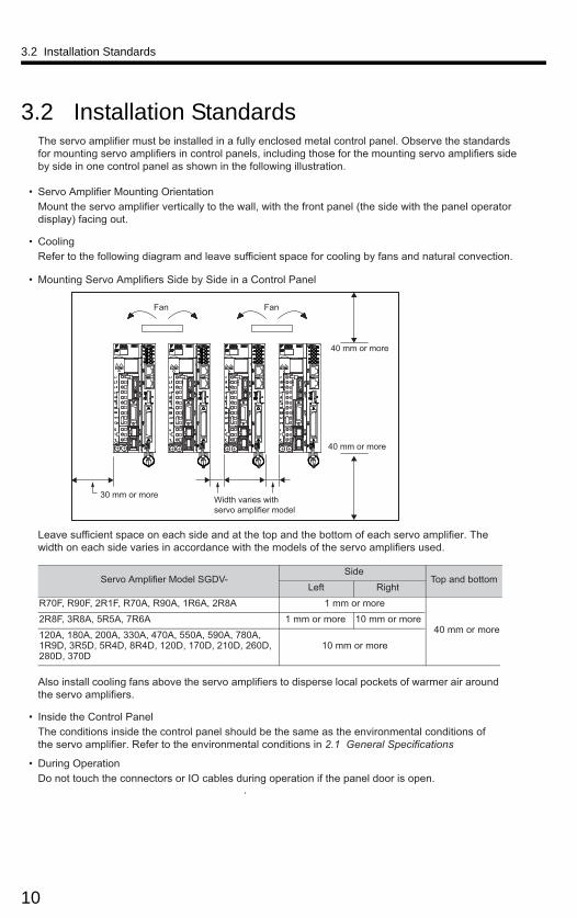
3.2 Installation StandardsThe servo amplifier must be installed in a fully enclosed metal control panel. Observe the standards for mounting servo amplifiers in control panels, including those for the mounting servo amplifiers side by side in one control panel as shown in the following illustration.
• Servo Amplifier Mounting OrientationMount the servo amplifier vertically to the wall, with the front panel (the side with the panel operator display) facing out.
• CoolingRefer to the following diagram and leave sufficient space for cooling by fans and natural convection.
• Mounting Servo Amplifiers Side by Side in a Control Panel
Leave sufficient space on each side and at the top and the bottom of each servo amplifier. The width on each side varies in accordance with the models of the servo amplifiers used.
Also install cooling fans above the servo amplifiers to disperse local pockets of warmer air around the servo amplifiers.
• Inside the Control PanelThe conditions inside the control panel should be the same as the environmental conditions of the servo amplifier. Refer to the environmental conditions in 2.1 General Specifications .
• During OperationDo not touch the connectors or IO cables during operation if the panel door is open.
.
30 mm or more
40 mm or more
40 mm or more
Fan Fan
Width varies with servo amplifier model
Servo Amplifier Model SGDV-Side
Top and bottomLeft Right
R70F, R90F, 2R1F, R70A, R90A, 1R6A, 2R8A 1 mm or more
40 mm or more2R8F, 3R8A, 5R5A, 7R6A 1 mm or more 10 mm or more
120A, 180A, 200A, 330A, 470A, 550A, 590A, 780A, 1R9D, 3R5D, 5R4D, 8R4D, 120D, 170D, 210D, 260D, 280D, 370D
10 mm or more
10
3.3 Dimensions
3.3.1 MP2600iec Controller
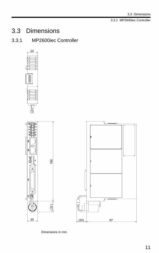
3.3 Dimensions
3.3.1 MP2600iec Controller
20
160
(22
)
97(20)
Dimensions in mm.
20
11

3.3 Dimensions
3.3.1 MP2600iec Controller
This page left intentionally blank
12

4.1 CN13 Connection Diagram
4 Inputs/Outputs
4.1 CN13 Connection Diagram
L Load
NOTE: For a more detailed circuit drawing, see section 4.4.2.
* DO_07 can also be used as a high speed output when configured via parameter 1050
External Fuse(installed bycustomer)
FG
1
L
External Device
-10 +10V
V
-10 +10VFG
External Device
Pulse Generator
FG
Ext
erna
l Inp
utS
igna
l
26
227
45
29306
31
10349
35
133814
15
16
17
39
40
41
42
AOAO_GND
AIAI_GND
PA+PA-
PB+PB-GNDGND
PILC(24V)PILC(12V)PILC(5V)PIL
DICOMDICOMDI_00DI_01DI_02DI_03DI_04DI_05DI_06DI_07
+-
+15V
-15V
+-
+15V
-15V
+5V
Analog Output
Analog Input
Encoder Interface
Z-phase Latch Input
Digital Input
Digital Output
Polyswitch Device:A self-resetting fuse if excessivecurrent is drawnfrom the output
FG Connector Shell)
CN13
Latch Input
21
11
DO_00+
DO_00-
46
36
DO_01+
DO_01-
22
12
DO_02+
DO_02-
47
37
DO_03+
DO_03-
23
18
DO_04+
DO_04-
48
43
DO_05+
DO_05-
24
19
DO_06+
DO_06-
49
44
* DO_07+
* DO_07-
7 + Battery
32 - Battery
Connect a positive voltage to pin 10, 34, or 9 based on signal level
L +24VDC
0V
L +24VDC
0VL +24VDC
0VL +24VDC
0VL +24VDC
0VL +24VDC
0VL +24VDC
0VL +24VDC
0V
13

4.2 CN13 Connection Description
4.2 CN13 Connection DescriptionNumerical AlphabeticalCN 13 Pin Code Description
1 AO Analog Output2 AI Analog Input3 n/c no connection4 PA+ Encoder A phase +5 PA- Encoder A phase -6 GND Encoder ground7 BAT + SRAM Positive Battery input8 n/c no connection9 PILC PC+ / External Encoder Latch +5V10 PILC PC+ / External Encoder Latch +24V11 DO_00- Digital Output 0 -12 DO_02- Digital Output 2 -13 DICOM Digital Input Common14 DI_00 Digital Input 015 DI_02 Digital Input 216 DI_04 Digital Input 417 DI_06 Digital Input 618 DO_04- Digital Output 4 -19 DO_06- Digital Output 6 -20 n/c no connection21 DO_00+ Digital Output 0 +22 DO_02+ Digital Output 2 +23 DO_04+ Digital Output 4 +24 DO_06+ Digital Output 6 +25 n/c no connection26 AO_GND Analog Output Ground27 AI_GND Analog Input Ground28 n/c no connection29 PB+ Encoder B phase +30 PB- Encoder B phase -31 GND Encoder ground32 BAT - SRAM Negative Battery input33 n/c no connection34 PILC PC+ / External Encoder Latch +12V35 PIL PC- / External Encoder Latch36 DO_01- Digital Output 1 -37 DO_03- Digital Output 3 -38 DICOM Digital Input Common39 DI_01 Digital Input 140 DI_03 Digital Input 341 DI_05 Digital Input 542 DI_07 Digital Input 743 DO_05- Digital Output 5 -44 DO_07- Digital Output 7 -45 n/c no connection46 DO_01+ Digital Output 1 +47 DO_03+ Digital Output 3 +48 DO_05+ Digital Output 5 +49 DO_07+ Digital Output 7 +50 n/c no connection
Description Code CN 13 PinAnalog Input AI 2Analog Input Ground AI_GND 27Analog Output AO 1Analog Output Ground AO_GND 26Digital Input 0 DI_00 14Digital Input 1 DI_01 39Digital Input 2 DI_02 15Digital Input 3 DI_03 40Digital Input 4 DI_04 16Digital Input 5 DI_05 41Digital Input 6 DI_06 17Digital Input 7 DI_07 42Digital Input Common DICOM 13Digital Input Common DICOM 38Digital Output 0 - DO_00- 11Digital Output 0 + DO_00+ 21Digital Output 1 - DO_01- 36Digital Output 1 + DO_01+ 46Digital Output 2 - DO_02- 12Digital Output 2 + DO_02+ 22Digital Output 3 - DO_03- 37Digital Output 3 + DO_03+ 47Digital Output 4 - DO_04- 18Digital Output 4 + DO_04+ 23Digital Output 5 - DO_05- 43Digital Output 5 + DO_05+ 48Digital Output 6 - DO_06- 19Digital Output 6 + DO_06+ 24Digital Output 7 - DO_07- 44Digital Output 7 + DO_07+ 49Encoder A phase - PA- 5Encoder A phase + PA+ 4Encoder B phase - PB- 30Encoder B phase + PB+ 29Encoder ground GND 6Encoder ground GND 31no connection n/c 3no connection n/c 8no connection n/c 20no connection n/c 25no connection n/c 28no connection n/c 33no connection n/c 45no connection n/c 50PC- / External Encoder Latch PIL 35PC+ / External Encoder Latch+12V PILC 34PC+ / External Encoder Latch+24V PILC 10PC+ / External Encoder Latch +5V PILC 9SRAM Negative Battery input BAT - 32SRAM Positive Battery input BAT + 7
Note: DO_07 can also be used as a high speed output when configured via parameter 1050. See the PLCopen Plus Axis Parameters for more details.
14

4.3 External Encoder Interface
4.3 External Encoder Interface
Two RS-422 compatible inputs are provided for encoder phases A and B. One position latch input which supports a 5V, 12V, or 24V digital input signal is provided.
Encoder Input Circuit (PILC refers to positive input side of sensor)
Item Specification
Number of channels One channel (Phase A, Phase B, Index pulse)
Input circuit
Phase A & B: 5V differential input (RS-422 compatible), non-insulated. Maximum frequency 4MHz.
Index pulse: 5V/12V/24V photo coupler input. Maximum frequency 500kHz (pre-quadrature. This signal is used for external encoder latch.
Counter modes Quadrature, pulse and direction, up/down
PIL Latch input Hardware latency: 5s or less, sinking input
DI_01 Latch Input Hardware latency: 600s or less, sinking input
R
4
5
+5V
0V
Phase A
Pulse generator
R
29
30
+5V
0V
Phase B
6
PB+
PB-
PA+
PA-
GND
35 PILR
9 PILC(5V)
34
10
R
R
+5V
R
GND31
PILC(12V)
PILC(24V)
CN13 Connector
15

4.4 Controller Digital I/O
4.4.1 Inputs
4.4 Controller Digital I/O
4.4.1 Inputs• 8 general purpose• Optically isolated• 24 V @ 5 mA• Entire bank is configurable as either current sinking or sourcing via
connection of common
Digital Input Circuit
To configure all controller inputs as sinking, wire +24VDC to pins 13 and 38. To configure all controller inputs as sourcing, wire 0VDC to pins 13 and 38. Refer to diagram in Section 5.1.
16

4.4 Controller Digital I/O
4.4.2 Outputs
4.4.2 Outputs• 8 general purpose • Optically isolated• 24 V @ 50 mA • Current source or sink (connection to both emitter and collector are
provided)• High speed digital output feature can set DO_07 within 13s of passing a
specified encoder position. See Axis Parameters in the PLCopen Plus Function Block Manual to configure.
Digital Output Circuit
Connection Examples of Output Circuits • Relay Circuit Example
• Line Receiver Circuit Example
0 V
Relay5 to 24 VDC
SERVOPACK
SERVOPACK5 to 12 VDC
17
4.5 Sigma-5 I/O
4.4.2 Outputs
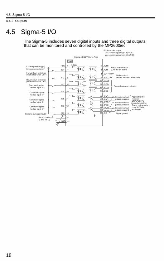
4.5 Sigma-5 I/OThe Sigma-5 includes seven digital inputs and three digital outputs that can be monitored and controlled by the MP2600iec.
SO1+ / BK+
SO1- / BK- /SO2+
/SO2-
/SO3+
ALM+
ALM-
1
2 23
24
3
4
+24V 3.3kΩ
/SI1
/SI2
/SI3
/SI4
/SI5
6
8
10
9
11
12 /SI6
/SI0 BAT+
BAT-
13
14
15
7
/SO3-
PBO
PCO /PBO
PAO /PAO
/PCO
19
25
26
17 18
20 21 22 16 SG
*1
CN1
Command option module input 3*4
Command optionmodule input 4*4
Command optionmodule input 5*4
Command optionmodule input 6*4
Encoder output pulses phase A Encoder output pulses phase B
Encoder output pulses phase C
General-purpose outputs
General-purpose input 0
Backup battery*2
(2.8 to 4.5 V)
Reverse run prohibited (Prohibited when OFF)
Forward run prohibited (Prohibited when OFF)
Servo alarm output (OFF for an alarm)
Photocoupler outputMax. operating voltage: 30 VDCMax. operating current: 50 mA DC
Brake output (Brake released when ON)
Applicable line receiver SN75ALS175 manufactured by Texas Instruments or an MC3486 equivalent
Signal ground
Sigma-5 SGDV Servo Amp
Control power supply for sequence signal*3
18

4.6 Analog I/O
4.6.1 Analog Input
4.6 Analog I/O
4.6.1 Analog Input
Analog Input Circuit
Item Specification
Analog input range -10V ~ +10V
Number of input channels 1
Electrical isolation None
Absolute maximum input ± 15V
Input Impedance 20k
Resolution 16 bit
Accuracy25°C ±0.1% (± 10mV)
0 ~ 55°C ±0.3% (± 30mV)
Input filter
Time constant =130s (63.2% rise time)
Delay time1ms maximum (for full-range -10V to +10V slew)
Conversion time 50s
GND
To A/DConversion
AI_GND
AI
10K
10K20K
CN13 Connector
2
27
19

4.6 Analog I/O
4.6.2 Analog Output
4.6.2 Analog Output
Analog Output Circuit
Item Specification
Analog output range -10V ~ +10V
Number of output channels 1
Electrical isolation None
Maximum load current ± 5mA
Resolution 16 bit
Accuracy25°C ±0.45% (± 45mV)
0 ~ 55°C ±0.60% (± 60mV)
Output delay time less than 1ms
CN13 Connector
126
AO
AO_GND+-
+15V
-15V
20

5.1 Switch Settings
S
5 DIP Switches
5.1 Switch Settings
S11
DHCPEINITCNFGINTSUPSTOP
NO
witch Name Setting Operating ModeSetting for
Normal Operation
Details
1 STOPON
User program execution inhibited OFF Inhibits user program execution
OFF Normal operation
2 SUPON
Firmware programming mode OFF Enables controller firmware programming.
(See Section 11)OFF Normal operation
3 INIT
ONSRAM/clock initialization and configuration bypass mode OFF
Set to ON to bypass the stored configuration (e.g. in case of a configuration problem that prevents controller startup) or to initialize the SRAM contents and clock settings after backup power has been lost (See Section 7.1).
OFF Normal operation
4 CNFG
ON Normal operationON Always set to ON
OFFDo not set (reserved for future use)
5 E-INITON
Force Ethernet address setting for Port A to 192.168.1.1 and Port B to 192.168.2.1
OFF Enables use of the default Ethernet addresses
OFF Normal Operation
6 DHCP
ONDHCP-configured IP settings
OFFEnables use of DHCP for IP setting configuration
OFFManually-configured IP settings
21

5.1 Switch Settings
This page left intentionally blank
22

6 LED Outputs
6 LED OutputsThe following table shows the indicators that show the operating status of the controller and error information.
Indicator Color Status
RDY Green Lit during normal operation.
RUN Green Lit during execution of user program.
ALM Red Lit when alarm occurs.
ERR Red Lit when malfunction occurs.
CTRL Green Lit when option card is communicating to the servo amplifier.
BAT Red Lit during battery alarm.
TRX A Green Lit during Ethernet CN11A activity.
LINK A Green Lit during Ethernet CN11A link up.
TRX B Green Lit during Ethernet CN11B activity.
LINK B Green Lit during Ethernet CN11B link up.
RDY
ALM
BAT
RUN
ERR
CTRL
LINKA
LINKB
TRXA
TRXB
23

6 LED Outputs
This page left intentionally blank
24
7.1 Battery Installation
7 Battery
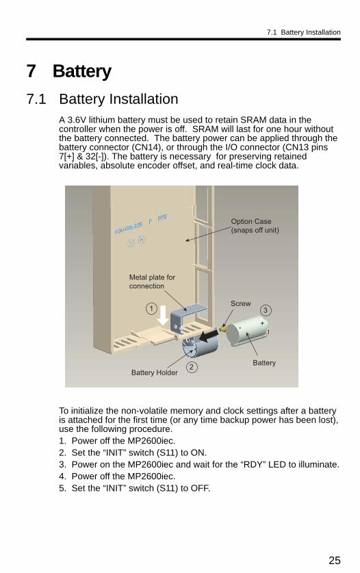
7.1 Battery InstallationA 3.6V lithium battery must be used to retain SRAM data in the controller when the power is off. SRAM will last for one hour without the battery connected. The battery power can be applied through the battery connector (CN14), or through the I/O connector (CN13 pins 7[+] & 32[-]). The battery is necessary for preserving retained variables, absolute encoder offset, and real-time clock data.
To initialize the non-volatile memory and clock settings after a battery is attached for the first time (or any time backup power has been lost), use the following procedure.1. Power off the MP2600iec.2. Set the “INIT” switch (S11) to ON.3. Power on the MP2600iec and wait for the “RDY” LED to illuminate.4. Power off the MP2600iec.5. Set the “INIT” switch (S11) to OFF.
Option Case(snaps off unit)
Screw
Battery
Metal plate for connection
Battery Holder
1
2
3
+-
25

7.1 Battery Installation
Battery Holder Installation Instructions:
1. Remove the plastic case from the controller by pressing the tabs at the top and bottom.
2. Insert the tab of the metal plate into the last vent slot on the bottom front of the case as shown.
3. Line up the hole in battery holder with the hole in the metal plate and secure the battery holder with the screw provided.
4. Attach the extension cable to the battery and place the battery into the battery holder with the cable facing forward.
5. Attach the plastic case to the controller.
6. Plug the battery extension cable into the battery connector (CN14).
26

8.1 Connectivity Information
8 Ethernet
8.1 Connectivity InformationThe MP2600iec supports 100MB speeds exclusively. Two separate networks are possible using both CN11A and CN11B. A default gateway can be specified only for the network attached to CN11A.
8.2 Ethernet Connector Details
Ethernet Connector Specification and Pin ArrayThe following table provides the Ethernet connector specifications.
The following table provides Ethernet connector pin array / indicator light details.
Connector Name
Number of Pins
Connector Model
Module Side Cable Side Manufacturer
Ethernet 8 RJ-45 CAT5 Socket RJ-45 CAT5 Plug Pulse Engineering
Pin Number Signal Name Description
1 TXD+ Transmitted data + side
2 TXD- Transmitted data – side
3 RXD+ Received data + side
4 – –
5 – –
6 RXD- Received data – side
7 – –
8 – –
Ethernet
27
8.3 Ethernet Cable
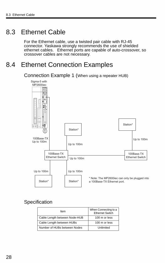
8.3 Ethernet CableFor the Ethernet cable, use a twisted pair cable with RJ-45 connector. Yaskawa strongly recommends the use of shielded ethernet cables. Ethernet ports are capable of auto-crossover, so crossover cables are not necessary.
8.4 Ethernet Connection Examples
Connection Example 1 (When using a repeater HUB)
Specification
ItemWhen Connecting to a
Ethernet Switch
Cable Length between Node-HUB 100 m or less
Cable Length between HUBs 100 m or less
Number of HUBs between Nodes Unlimited
100Base-TXEthernet Switch
Sigma-5 with MP2600iec
100Base-TXEthernet Switch
100Base-TX
* Note: The MP2600iec can only be plugged intoa 100Base-TX Ethernet port.
Station*
Station*Station*
Up to 100mUp to 100m
Up to 100m
Up to 100m
Up to 100m
Station*
Up to 100m
28

8.4 Ethernet Connection Examples
Connection Example 2
100 Base-TX (up to 100m)
Sigma-5 with MP2600iec
Note: The MP2600iec can only be pluggedinto a 100Base-TX Ethernet port.
Caution
High frequency wave noise from other devices in the installation environment may cause errors in communications. When designing a system, use protective measures to avoid the influence of high frequency wave noise as follows:
1. WiringWire Ethernet cables so that they are well-separated from other cable systems such as the main circuit or power lines.
2. Communication system (Ethernet)• Communicate data to a remote device.• Yaskawa strongly recommends shielded Ethernet cables.
3. Attach a ferrite core.This will help reduce the occurrence of electrical interference.Recommended ferrite core:
Model Manufacturer
E04SR301334 Seiwa Electric Mfg. Co., Ltd
29

8.4 Ethernet Connection Examples
Connection Example 3
100Base-TXEthernet Switch
MotionWorks IEC
Sigma-5 with MP2600iec
Core
Core
100Base-TX
Servomotor
Station*
* Note: The MP2600iec can only be plugged into a 100Base-TX Ethernet port
30

9.1 CBK-U-MP2B-xx
9 Cable Diagrams
9.1 CBK-U-MP2B-xx
Terminal Block - Controller
CBK-U-MP2B-XX Function Chart for MP2600iec
I = Input, O = Output, P = Power
Pin No.
Signal Name
I/O Function Pin No.
Signal Name
I/O Function
1 AO O Analog output 26 AO_GND O Analog output ground2 AI I Analog input 27 AI_GND I Analog input ground3 - - - 28 reserved - 4 PA+ I Phase A pulse (+) 29 PB+ I Phase B pulse (+)5 PA- I Phase A pulse (-) 30 PB- I Phase B pulse (-)6 GND P Encoder input ground 31 GND P Encoder input ground7 BAT+ P Controller SRAM Battery (+) 32 BAT- P Controller SRAM Battery (-)8 - - - 33 - - -
9 PILC5V I Phase-C latch pulse (-) for 5VDC input 34 PILC12V I Phase-C latch pulse (-) for 12VDC
input
10 PILC24V I Phase-C latch pulse (-) for 24VDC input 35 PIL I Phase-C latch pulse (+)
11 DO_00- O Digital output 0 (-) 36 DO_01- O Digital output 1 (-)12 DO_02- O Digital output 2 (-) 37 DO_03- O Digital output 3 (-)13 DICOM I Digital input common 38 DICOM I Digital input common
14 DI_00 I Digital input 0 39 DI_01 I Digital input 1(shared with pulse latch input)
15 DI_02 I Digital input 2 40 DI_03 I Digital input 316 DI_04 I Digital input 4 41 DI_05 I Digital input 517 DI_06 I Digital input 6 42 DI_07 I Digital input 718 DO_04- O Digital output 4 (-) 43 DO_05- O Digital output 5 (-)19 DO_06- O Digital output 6 (-) 44 DO_07- O Digital output 7 (-)20 - - - 45 - - - 21 DO_00+ O Digital output 0 (+) 46 DO_01+ O Digital output 1 (+)22 DO_02+ O Digital output 2 (+) 47 DO_03+ O Digital output 3 (+)23 DO_04+ O Digital output 4 (+) 48 DO_05+ O Digital output 5 (+)
24 DO_06+ O Digital output 6 (+) 49 DO_07+ O Digital output 7 (+) (shared with position agreement 'COIN' signal)
25 - - - 50 - - -
31

9.2 CFC-U-MP2B-xx
9.2 CFC-U-MP2B-xx
Flying Lead - Controller
Model X =Cable Length
CFC-U-MP2B-A5 500 mm
CFC-U-MP2B-01 1000 mm
CFC-U-MP2B-03 3000 mm
Dimensions in mm
Pin No.
Color (Solid/Band)
Signal Name
I/O Function Pin No.
Color (Solid/Band)
Signal Name
I/O Function
1 BLK/RED AO O Analog output 26 RED/BLK AO_GND O Analog output ground
2 BLK/WHT AI I Analog input 27 WHT/BLK AI_GND I Analog input ground
3 RED/GRN - - - 28 GRN/RED - - -
4 BLK/BLU PA+ I Phase A pulse (+) 29 BLK/BRN PB+ I Phase B pulse (+)
5 BLU/BLK PA- I Phase A pulse (-) 30 BRN/BLK PB- I Phase B pulse (-)
6 RED/BLU GND P Encoder input ground 31 BLU/RED GND P Encoder input
ground
7 RED/WHT BAT+ P Controller SRAM Battery (+) 32 WHT/RED BAT- P Controller SRAM
Battery (-)8 BLK/GRN - - - 33 GRN/BLK - - -
9 BLK/YEL PILC5V I Phase-C latch pulse (-) for 5VDC input 34 ORG/BLK PILC12V I Phase-C latch pulse
(-) for 12VDC input
10 BLK/ORG PILC24V I Phase-C latch pulse (-) for 24VDC input 35 YEL/BLK PIL I Phase-C latch pulse
(+)11 RED/YEL DO_00- O Digital output 0 (-) 36 WHT/ORG DO_01- O Digital output 1 (-)
12 RED/BRN DO_02- O Digital output 2 (-) 37 BLU/YEL DO_03- O Digital output 3 (-)
13 RED/ORG DICOM I Digital input common 38 ORG/RED DICOM I Digital input common
14 GRN/WHT DI_00 I Digital input 0 39 WHT/GRN DI_01 IDigital input 1 (shared with pulse latch input)
15 GRN/BLU DI_02 I Digital input 2 40 BLU/GRN DI_03 I Digital input 3
16 GRN/YEL DI_04 I Digital input 4 41 YEL/GRN DI_05 I Digital input 5
17 GRN/BRN DI_06 I Digital input 6 42 BRN/GRN DI_07 I Digital input 7
18 GRN/ORG DO_04- O Digital output 4 (-) 43 BLU/BRN DO_05- O Digital output 5 (-)
19 WHT/BLU DO_06- O Digital output 6 (-) 44 BLU/ORG DO_07- O Digital output 7 (-)
20 WHT/YEL - - - 45 YEL/WHT - - -
21 YEL/RED DO_00+ O Digital output 0 (+) 46 ORG/WHT DO_01+ O Digital output 1 (+)
22 BRN/RED DO_02+ O Digital output 2 (+) 47 YEL/BLU DO_03+ O Digital output 3 (+)
23 ORG/GRN DO_04+ O Digital output 4 (+) 48 BRN/BLU DO_05+ O Digital output 5 (+)
24 BLU/WHT DO_06+ O Digital output 6 (+) 49 ORG/BLU DO_07+ O
Digital output 7 (+)(shared with position agreement 'COIN' signal)
25 WHT/BRN - - - 50 BRN/WHT - - -
32

9.3 SBK-U-VBA-xx
9.3 SBK-U-VBA-xx
Terminal Block - Servo Amplifier.
Signal Function1 /BK+ (/SO1+) Brake interlock output (+) (General purpose output 1 (+))2 /BK- (/SO1-) Brake interlock output (-) (General purpose output 1 (-))3 ALM+ Servo alarm output (+)4 ALM- Servo alarm output (-)5 -6 +24VIN Control power supply for sequence signal input7 P-OT (/SI1) Forward run prohibited input (General purpose input 1)8 N-OT (/SI2) Reverse run prohibited input (General purpose input 2)9 /DEC (/SI3) Zero-point return deceleration switch input (General purpose input 3)10 /EXT1 (/SI4) External latch signal 1 input (General purpose input 4)11 /EXT2 (/SI5) External latch signal 2 input (General purpose input 5)12 /EXT3 (/SI6) External latch signal 3 input (General purpose input 6)13 /SI0 General purpose input 014 BAT (+) Battery (+) input15 BAT (-) Battery (-) input16 SG Signal ground17 PAO Phase-A pulse output (+)18 /PAO Phase-A pulse output (-)19 PBO Phase-B pulse output (+)20 /PBO Phase-B pulse output (-)21 PCO Phase-C pulse output (+)22 /PCO Phase-C pulse output (-)23 /SO2+ General purpose output 2 (+)24 /SO2- General purpose output 2 (-)25 /SO3+ General purpose output 3 (+)26 /SO3- General purpose output 3 (-)
SGDV Mechatrolink-II type / SGDV Option typePin No.
SBK-U-VBA-xx Function Chart for SGDV Servo Amplifier
Note: General purpose input and output signals are shown with their default signals assigned - signal assignment may have been changed by parameter
33

9.4 JZSP-CSI02-x-E
9.4 JZSP-CSI02-x-E
Flying Lead - Servo Amplifier
/BK+/BK−ALM+ALM−
–+24VINP-OTN-OT/DEC/EXT1/EXT2/EXT3/SI0
BAT +BAT −
SGPAO/PAOPBO/PBOPCO/PCO/SO2+/SO2−/SO3+/SO3−
123456789
1011121314151617181920212223242526
BlueBluePinkPink
GreenGreenOrangeOrange
GrayGrayBlueBluePinkPink
GreenGreenOrangeOrange
GrayGrayBlueBluePinkPink
GreenGreen
RedBlackRed
BlackRed
BlackRed
BlackRed
BlackRed
BlackRed
BlackRed
BlackRed
BlackRed
BlackRed
BlackRed
BlackRed
Black
11111111112222222222333333
Pin No.WireColorSignal
MarkingColor
SERVOPACK End
DotsLead
Marker
1234567891011121314151617181920212223242526
Represents twisted-pair wires.
Host Controller End
Model Cable Length
JZSP-CSI02-1-E 1000 mm
JZSP-CSI02-2-E 2000 mm
JZSP-CSI02-3-E 3000 mm
SERVOPACK EndConnector 10126-6000EL (by Sumitomo 3M Ltd.)Shell 10326-52A0-008
Cable (Ivory)SSRFPVV-SB AWG#28 × 13PUL20276 VW-1SC
L
37
.2
14 100 +10-0
3 Dia. Wire Markers
( 6.3
Dia
.)
Dimensions in mm
34

10 Firmware Upgrade
10 Firmware UpgradeIt is possible to upgrade the Controller firmware in the field.
For detailed instructions, please refer to Product Note PN.MCD.08.083: Upgrading the MP2iec Controller Firmware. This document may be downloaded from our website, www.yaskawa.com.
35

10 Firmware Upgrade
This page left intentionally blank
36

11 EMC Installation Conditions
11 EMC Installation ConditionsThis section describes the recommended installation conditions that satisfy EMC guidelines for each model of the SGDV SERVOPACK. The conditions required for the standard type (base-mounted) of the SERVOPACK are described. Refer to this section for other SERVOPACK models such as the rack-mounted types as well.
This section describes the EMC installation conditions satisfied in test conditions prepared by Yaskawa. The actual EMC level may differ depending on the actual system’s configuration, wiring, and other conditions. However, because this product is built-in, check that the following conditions are still met after being installed in the user’s product.
The applicable standards are EN55011/A2 group 1 class A, EN61800-3, and EN61000-6-2.
Ethernet Communication Cables: Use a category 5 or higher cable with double, aluminum tape and braided shielding according to the standard EN50288-2-2.
37

11 EMC Installation Conditions
Single-phase 100 VSGDV-FE1A ( = R70, R90, 2R1, 2R8) + SGDV-OCC02A
Symbol Cable Name Specification
I/O signal cable Shield cable
Safety signal cable Shield cable
Motor main circuit cable Shield cable
Encoder cable Shield cable
Main circuit cable Shield cable
Ethernet communication cable Shield cable
U, V, WL1, L2
L1C, L2C
CN2
CN1
PE
PE
1
3
4
5
CN8
2
PCController 6 C
N11
A/B
MP
2600
iec
Power supply:Single-phase 100 VAC
Encoder
Servomotor
BrakeNoise filter
Brake Power Supply
Surge absorber
Two turn
Two turn Two turn
Cor
e
Cor
eC
ore
Cor
e
Core Core
Cor
e
GeneralI/O Safety unit
Cla
mp
Cla
mp
Cla
mp
Clamp
Cla
mp
Shield box
One turn
One turn
One turn
General I/O1 C
N13
MP
2600
iec
Cor
e
Cla
mp
One turn
SERVOPACK
38

11 EMC Installation Conditions
Three-phase 200 VSGDV-AE1A ( = R70, R90, 1R6, 2R8, 3R8, 5R5, 7R6) + SGDV-OCC02A
Symbol Cable Name Specification
I/O signal cable Shield cable
Safety signal cable Shield cable
Motor main circuit cable Shield cable
Encoder cable Shield cable
Main circuit cable Shield cable
Ethernet communication cable Shield cable
U, V, WL1, L2, L3
L1C, L2C
CN2
CN1
PE
PE
21
3
4
5
CN8
Power supply: Three-phase 200 VAC
Shield box
SERVOPACK
Encoder
Servomotor
Brake
Cla
mp
Cla
mp
Cla
mp
Cla
mp
Noise filter
Brake Power Supply
Surge absorber
Two turn Two turn
Cor
e
Cor
eC
ore
Cor
e
Core Core
Clamp
GeneralI/O Safety unit
One turn
One turn
PCController 6 C
N11
A/B
MP
2600
iec
Cor
e
One turn
General I/O1 C
N13
MP
2600
iec
Cor
e
Cla
mp
One turn
39

11 EMC Installation Conditions
Three-phase 200 VSGDV-AE1A ( = 120) + SGDV-OCC02A
Symbol Cable Name Specification
I/O signal cable Shield cable
Safety signal cable Shield cable
Motor main circuit cable Shield cable
Encoder cable Shield cable
Main circuit cable Shield cable
Ethernet communication cable Shield cable
U, V, WL1, L2, L3
L1C, L2C
CN2
CN1
PE
PE
21
3
4
5
CN8
Power supply: Three-phase 200 VAC C
lam
p Noise filter
Surge absorber
Brake Power Supply
SERVOPACK
Shield box
One turn
Two turn
Cor
eC
ore
Cla
mp
Cla
mp
Cla
mp
Two turn
Safety unitGeneralI/O
Core Core
Clamp
Encoder
Servomotor
Brake
PCController 6 C
N11
A/B
MP
2600
iec
Cor
e
One turn
General I/O1 C
N13
MP
2600
iec
Cor
e
Cla
mp
One turn
40

11 EMC Installation Conditions
Three-phase 200 VSGDV-AE1A ( = 180, 200, 330) + SGDV-OCC02A
Symbol Cable Name Specification
I/O signal cable Shield cable
Safety signal cable Shield cable
Motor main circuit cable Shield cable
Encoder cable Shield cable
Main circuit cable Shield cable
Ethernet communication cable Shield cable
U, V, WL1, L2, L3
L1C, L2C
CN2
CN1
PE
PE
1
3
4
5
CN8
2
One turn
Power supply: Three-phase 200 VAC C
lam
p Noise filter
Surge absorber
Brake Power Supply
SERVOPACK
Shield box
Two turn
Cor
e
Cla
mp
Cla
mp
Cla
mp
Two turn
Safety unitGeneralI/O
Core Core
Clamp
Encoder
Servomotor
Brake
PCController 6 C
N11
A/B
MP
2600
iec
Cor
e
One turn
General I/O1 C
N13
MP
2600
iec
Cor
e
Cla
mp
One turn
41

11 EMC Installation Conditions
Three-phase 200 VSGDV-AE1A ( = 470, 550, 590, 780) + SGDV-OCC02A
Symbol Cable Name Specification
I/O signal cable Shield cable
Safety signal cable Shield cable
Motor main circuit cable Shield cable
Encoder cable Shield cable
Main circuit cable Shield cable
Regenerative resistor unit cable Non-shield cable
Cooling fan cable Shield cable
Ethernet communication cable Shield cable
U, V, WL1, L2, L3
L1C, L2C
B1, B2
CN2
CN1
PE
PE
1
3
4
5
CN8
2
6
7
Power supply: Three-phase 200 VAC
Shield box
SERVOPACK
Noise filter
Brake Power Supply
Surge absorber
GeneralI/O
Safety unit
Encoder
Servomotor
Brake
Cooling fanC
lam
p
Cla
mp
Cla
mp
Cla
mp
Cla
mp
Clamp Clamp
Regenerative resistor unit
PCController 8 C
N11
A/B
MP
2600
iec
Cor
e
One turn
General I/O1 C
N13
MP
2600
iec
Cor
e
Cla
mp
One turn
42

11 EMC Installation Conditions
Three-phase 400 VSGDV-DE1A ( = 1R9, 3R5, 5R4, 8R4, 120, 170) + SGDV-OCC02A
* 1. Products that have received CE marking are recommended for the 24 VDC power supply.* 2. Install the following noise filter on the power line between the single-phase 200 V power
supply and the 24 VDC power supply.Model number: FN2070-6/07 (SCHAFFNER).
* 3. For more information on this filter, refer to Sigma-5 Product Catalog (YEA-KAEPS80000042).
Symbol Cable Name Specification
I/O signal cable Shield cable
Safety signal cable Shield cable
Motor main circuit cable Shield cable
Encoder cable Shield cable
Control power cable Shield cable
Main circuit cable Shield cable
Ethernet communication cable Shield cable
U, V, W
L1, L2, L3
24 V, 0 V
CN2
CN1
PE
PE
1 2
3
6
5
CN8
4
SERVOPACK
Brake Power Supply
General I/O Safety unit
Encoder
Servomotor
Brake
Shield box
Cla
mp
Cla
mp
Cor
e
Cor
e
Cla
mp
Cor
e
Cor
eCla
mp
Noise filter*3
Core Core
Surge absorber
Surge absorber
Cor
e
Noise filter*2
Control power supply
24 VDC*1
Cla
mp
Clamp Clamp
One turn
One turn
Two turnTwo turn
One turn
Power supply: Single-phase
200 VAC
Power supply: Three-phase
400 VAC
PCController 7 C
N11
A/B
MP2
600i
ec
Cor
e
One turn
General I/O1 C
N13
MP2
600i
ec
Cor
e
Cla
mp
One turn
43

11 EMC Installation Conditions
Three-phase 400 VSGDV-DE1A ( = 210, 260, 280, 370) + SGDV-OCC02A
* 1. Products that have received CE marking are recommended for the 24 VDC power supply.* 2. Install the following noise filter on the power line between the single-phase 200 V power
supply and the 24 VDC power supply.Model number: FN2070-6/07 (SCHAFFNER).
* 3. For more information on this filter, refer to Sigma-5 Product Catalog (YEA-KAEPS80000042).
Symbol Cable Name Specification
I/O signal cable Shield cable
Safety signal cable Shield cable
Motor main circuit cable Shield cable
Encoder cable Shield cable
Control power cable Shield cable
Main circuit cable Shield cable
Regenerative resistor unit cable Non-shield cable
Ethernet communication cable Shield cable
U, V, W
L1, L2, L3
24 V, 0 V
CN2
CN1
PE
PE
1 2
3
6
5
CN8
B1, B2
7
4
Power supply: Single-phase
200 VAC
Power supply: Three-phase
400 VAC Cla
mp
Surge absorber
Surge absorber
Cla
mp Noise
filter*2
Noise filter*3
Brake Power Supply
Shield box
Control power supply
24 VDC*1
SERVOPACK
Encoder
Servomotor
Brake
Cla
mp
Cla
mp
Cla
mp
General I/O Safety unit
Clamp Clamp
Regenerative resistor unit
PCController 8 C
N11
A/B
MP
2600
iec
Cor
e
One turn
General I/O1 C
N13
MP
2600
iec
Cor
e
Cla
mp
One turn
44

11 EMC Installation Conditions
Attachment Methods of Ferrite Cores
Recommended Ferrite Core
Recommended Noise Filter and Surge AbsorberFor more information on recommended noise filters and surge absorbers, refer to Sigma-5 Product Catalog. (YEA-KAEPS800000 42)
Fixing the CableFix and ground the cable shield using a piece of conductive metal.
Example of Cable Clamp
Shield BoxA shield box, which is a closed metallic enclosure, is effective as reinforced shielding against electromagnetic interference (EMI) from SERVOPACKs. The structure of the box should allow the main body, door, and cooling unit to be attached to the ground. The box opening should be as small as possible.
Note: Do not connect the digital operator and the analog monitor cable to the SERVOPACK during operations. Connect them only when the machinery is stopped during maintenance.
One turn Two turn
Cable Name Ferrite Core Model Manufacturer
Motor main circuit cable ESD-SR-250 NEC TOKIN Corp.
Cable
Ferrite core
Cable
Ferrite core
Host controller side
Ground plate
Cable
Cableclamp
Shield (cable sheath stripped)
Fix and ground the cable shieldusing a piece of conductive metal.
Remove paint on mounting surface.
45

11 EMC Installation Conditions
46


IRUMA BUSINESS CENTER (SOLUTION CENTER)480, Kamifujisawa, Iruma, Saitama, 358-8555, JapanPhone: 81-4-2962-5696 Fax: 81-4-2962-6138
YASKAWA ELECTRIC CORPORATIONNew Pier Takeshiba South Tower, 1-16-1, Kaigan, Minatoku, Tokyo, 105-6891, JapanPhone: 81-3-5402-4511 Fax: 81-3-5402-4580http://www.yaskawa.co.jp
YASKAWA AMERICA, INC.2121 Norman Drive South, Waukegan, IL 60085, U.S.A.Phone: (800) YASKAWA (800-927-5292) or 1-847-887-7000 Fax: 1-847-887-7370http://www.yaskawa.com
YASKAWA ELÉTRICO DO BRASIL COMÉRCIO LTDA.Avenda Fagundes Filho, 620 Bairro Saude, São Paulo, SP04304-000, BrasilPhone: 55-11-3585-1100 Fax: 55-11-5581-8795http://www.yaskawa.com.br
YASKAWA ELECTRIC EUROPE GmbHHauptstraβe 185, 65760 Eschborn, GermanyPhone: 49-6196-569-300 Fax: 49-6196-569-398
YASKAWA ELECTRIC UK LTD.1 Hunt Hill Orchardton Woods, Cumbernauld, G68 9LF, United KingdomPhone: 44-1236-735000 Fax: 44-1236-458182
YASKAWA ELECTRIC KOREA CORPORATION7F, Doore Bldg. 24, Yeoido-dong, Youngdungpo-Ku, Seoul, 150-877, KoreaPhone: 82-2-784-7844 Fax: 82-2-784-8495
YASKAWA ELECTRIC (SINGAPORE) PTE. LTD.151 Lorong Chuan, #04-01, New Tech Park, 556741, SingaporePhone: 65-6282-3003 Fax: 65-6289-3003
YASKAWA ELECTRIC (SHANGHAI) CO., LTD.No. 18 Xizang Zhong Road, Room 1702-1707, Harbour Ring Plaza, Shanghai, 200001, ChinaPhone: 86-21-5385-2200 Fax: 86-21-5385-3299
YASKAWA ELECTRIC (SHANGHAI) CO., LTD. BEIJING OFFICERoom 1011A, Tower W3 Oriental Plaza, No. 1 East Chang An Ave., Dong Cheng District, Beijing, 100738, ChinaPhone: 86-10-8518-4086 Fax: 86-10-8518-4082
YASKAWA ELECTRIC TAIWAN CORPORATION9F, 16, Nanking E. Rd., Sec. 3, Taipei, TaiwanPhone: 886-2-2502-5003 Fax: 886-2-2505-1280
Published in U.S.A November, 2012MANUAL NO. YEA-SIA-IEC-6D
™