mp2889 duct, duct, goose i mean pipe. -...
TRANSCRIPT

© 2012 Autodesk
MP2889 – Duct, duct, goose… I mean pipe.
Darryl McClelland, LEED AP BD + C Adam BrysonBIM and Virtual Design Manager / Project Coordinator BIM Coordinator
Heapy Engineering Heapy Engineering
© 2012 Autodesk
Class Summary
We will focus on ductwork and piping and their related tools in an effort to
help you better understand and facilitate your design through the analysis
of your ductwork and piping systems. We will explore:
� Calculation fundamentals for both ductwork and piping and learn how they are incorporated in Revit MEP as well as the impacts they have on
sizing your ductwork and piping systems.
� Tools for routing and sizing your ductwork and piping systems.
� The System Inspector and how it can supplement the Duct and Pipe
Pressure Loss Reports.
� Adding color to your ductwork and piping analysis with Legends and Fills.
© 2012 Autodesk
Learning Objectives
At the end of this class, you will be able to:
� Better understand how engineering calculations have been incorporated into Revit MEP and how they can help facilitate your system design.
� Identify and avoid items that will negatively impact your model
performance.
� Identify Revit MEP tools that can help you better understand your design.
� Analyze the design of your systems and show the analysis data graphically.
� Use Revit MEP tools to do “heavy lifting” allowing you to be “productively
lazy” and “financially efficient”.
© 2012 Autodesk
At the end of this class we hope that everyone in this class will:
� Have a minimum of at least one take away or a “Huh, I didn’t know that” or “I learned something new in this class” since there is a varying
knowledge base in this room ranging from beginner to expert.
Our Class Goal/Objective

© 2012 Autodesk
Class Agenda
� Introductions…
� Housekeeping items…
� A potential training resource for your efforts…
� What is an engineer?
� Ductwork calculations…
� Piping calculations…
� Helpful tips…
� Duct and Pipe tools…
� Questions…

© 2012 Autodesk
Introductions…
� Darryl McClelland: BIM and Virtual Design Manager / Project
Coordinator helping to refine current workflows and processes as well as
implementing new technologies to leverage across MEP disciplines to help assist with project design challenges and improve collaboration
amongst the project team.
� Graduate of Purdue University, member of ASHRAE and ASPE, LEED AP (BD+C), and co-author of 6 nationally published books on BIM.
� 27 years of practical design experience in the MEP industry focused on
the mechanical design of complex research laboratories and institutional facilities to medical and professional office buildings, and everything in-
between.
© 2012 Autodesk
Introductions…
� Adam Bryson: BIM Coordinator helping to organize, develop, and
improve Heapy Engineering’s family library as well as streamlining
automation in workflow processes through scheduling, and the overall standardization of Revit MEP.
� A recovering Revit “junkie”. (4 days without using Revit MEP and
counting.)
� 11 years in the architectural and engineering industry and has been solely focused on the engineering aspect of the field for the past 3 years.

© 2012 Autodesk
Class Agenda
� Introductions…
� Housekeeping items…
� A potential training resource for your efforts…
� What is an engineer?
� Ductwork calculations…
� Piping calculations…
� Helpful tips…
� Duct and Pipe tools…
� Questions…
© 2012 Autodesk
Housekeeping items…
� Please turn off your cell phone or set it to silent or vibrate.
� If you need to take a call please step outside the classroom to do so.
� The class handout is posted on-line and will be re-posted with any
additions, changes, or modifications no later than two (2) weeks after the class.
� This class is being recorded so please be on your best behavior (this
mainly applies to Adam but I am trying not to be obvious to him there).
� Class evaluation forms are online. If you need help filling out the
evaluation form for this class please feel free to see Adam or me. We will gladly assist your efforts there.

© 2012 Autodesk
Class Agenda
� Introductions…
� Housekeeping items…
� A potential training resource for your efforts…
� What is an engineer?
� Ductwork calculations…
� Piping calculations…
� Helpful tips…
� Duct and Pipe tools…
� Questions…

© 2012 Autodesk
The Aubin Academy Master Series…
� Revit MEP 2013 and AutoCAD MEP 2013
� Paul F. Aubin, Darryl McClelland LEED AP BD + C, Martin Schmid PE, and Gregg Stanley
� Revit MEP 2012 and AutoCAD MEP 2012
� Paul F. Aubin, Darryl McClelland LEED AP BD + C, Martin Schmid PE, and Gregg Stanley
� SITE LICENSES ARE AVAILABLE!!!
� Autodesk University discounts available! www.paulaubin.com/au Code: SGESYKP2

© 2012 Autodesk
Class Agenda
� Introductions…
� Housekeeping items…
� A potential training resource for your efforts…
� What is an engineer?
� Ductwork calculations…
� Piping calculations…
� Helpful tips…
� Duct and Pipe tools…
� Questions…
© 2012 Autodesk
What is an engineer?
� Typically, if we can’t see, touch, or smell it, then we don’t believe it.
� I have created my own spreadsheets to perform certain tasks and
calculations, do I trust some one else's spreadsheets?
� Based on that, do I blindly trust software calculations? Why?� LIBABILITY, career, and reputation at stake.
� Do I have time to reverse engineer software calculations?� If I can’t touch, see, smell it, or reverse engineer the software calculations will
I trust / use the functionality?
� Does that allow me to use the product as intended, be “productively
lazy”, or “financially efficient” (or be on the golf course at 5:30 pm)?

© 2012 Autodesk
Class Agenda
� Introductions…
� Housekeeping items…
� A potential training resource for your efforts…
� What is an engineer?
� Ductwork calculations…
� Piping calculations…
� Helpful tips…
� Duct and Pipe tools…
� Questions…

© 2012 Autodesk
Ductwork Agenda
� How do you size your ductwork systems?
� Duct sizing in Revit MEP…

© 2012 Autodesk
How do you size your ductwork
systems?
© 2012 Autodesk
How do you size your ductwork systems?
� Velocity? Friction loss? Static Regain? Equal Friction? Friction loss
not to exceed velocity?
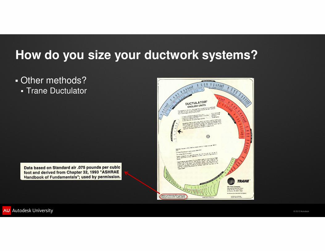
� Tables and charts?� Most tables and charts for air are calculated based on STP (Standard
Temperature and Pressure) properties which are 70º F, 0% RH, and 14.7 psia
(aka sea level) (2009 ASHRAE Handbook – Fundamentals, Chapter 21).
© 2012 Autodesk
How do you size your ductwork systems?
� Tables and charts� What happens when air is not 70º F at STP?
� “Change in barometric pressure, temperature, and humidity affect air
density, air viscosity, and Reynolds number. No corrections to Figure 9
(Friction Chart for Round Duct) are needed for (1) duct material with
medium-smooth roughness factor, (2) temperature variations of +/- 30º F
from 70º F, (3) elevations to 1500 ft., and (4) duct pressures from –20 to
+20 in. of water relative to ambient pressure. These individual variations
in temperature, elevation, and duct pressure result in duct losses within
+/- 5% of the standard air friction chart.” (2009 ASHRAE Handbook –
Fundamentals, Chapter 21).
© 2012 Autodesk
How do you size your ductwork systems?
� Other methods?� Trane Ductulator
© 2012 Autodesk
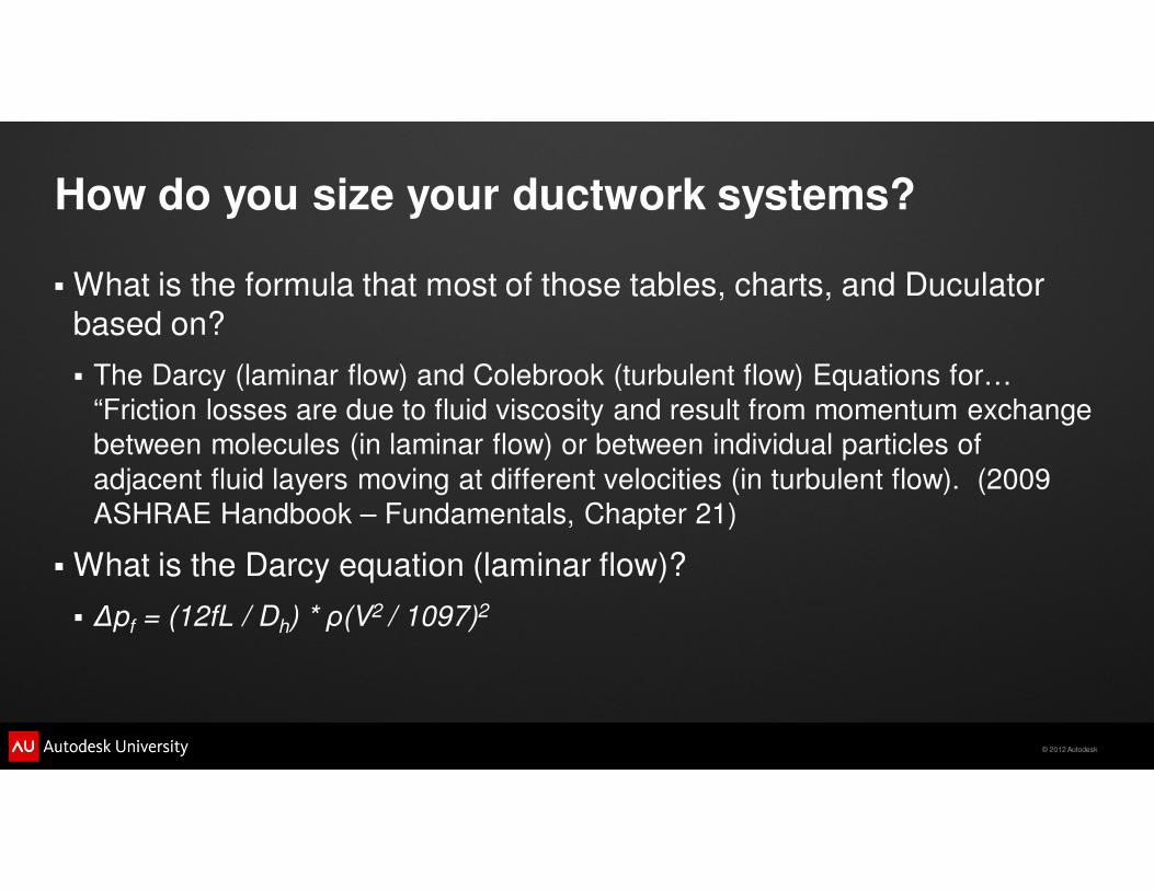
How do you size your ductwork systems?
� What is the formula that most of those tables, charts, and Duculator
based on?
� The Darcy (laminar flow) and Colebrook (turbulent flow) Equations for…
“Friction losses are due to fluid viscosity and result from momentum exchange
between molecules (in laminar flow) or between individual particles of
adjacent fluid layers moving at different velocities (in turbulent flow). (2009
ASHRAE Handbook – Fundamentals, Chapter 21)
� What is the Darcy equation (laminar flow)?
� ∆pf = (12fL / Dh) * ρ(V2 / 1097)2

© 2012 Autodesk
Duct Sizing in Revit MEP
© 2012 Autodesk
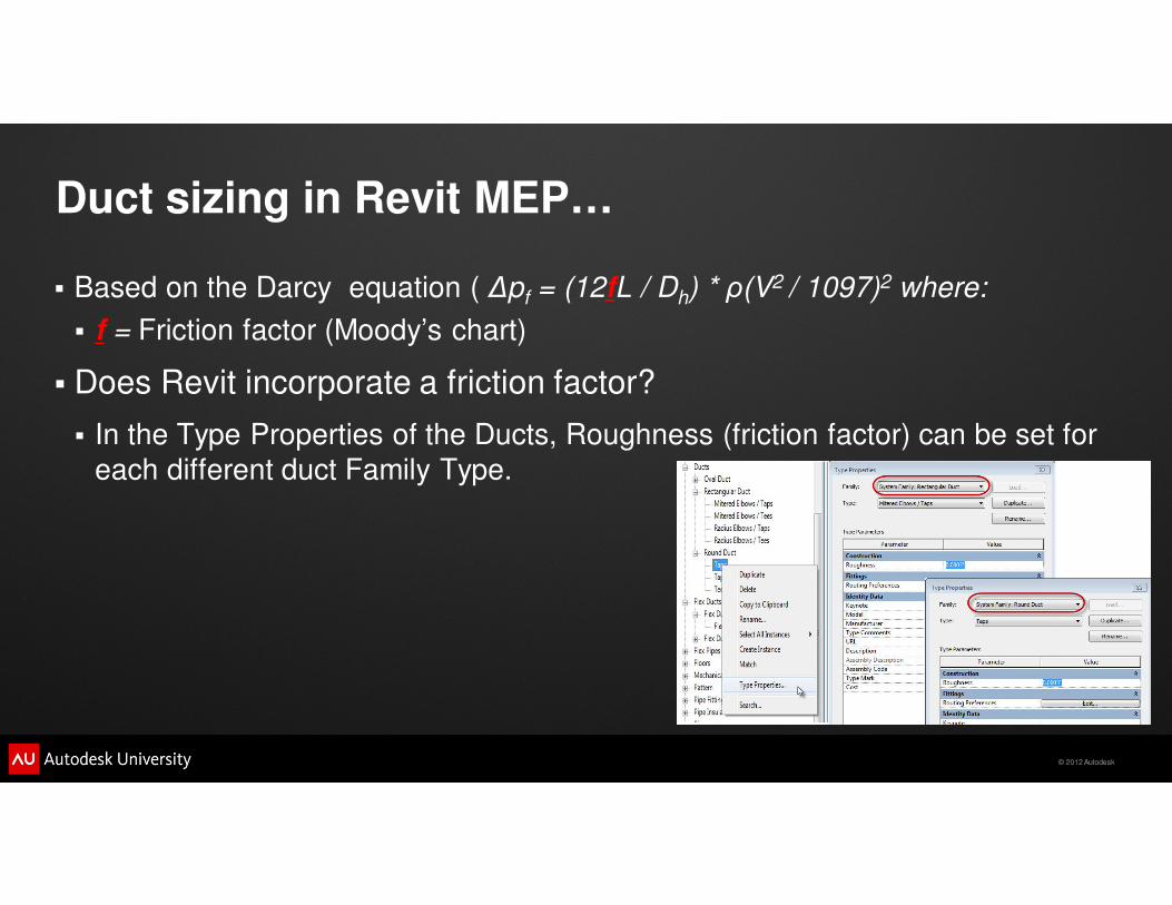
Duct sizing in Revit MEP…
� Based on the Darcy equation ( ∆pf = (12fL / Dh) * ρ(V2 / 1097)2 where:
� f = Friction factor (Moody’s chart)
� Does Revit incorporate a friction factor?
� In the Type Properties of the Ducts, Roughness (friction factor) can be set for
each different duct Family Type.
© 2012 Autodesk
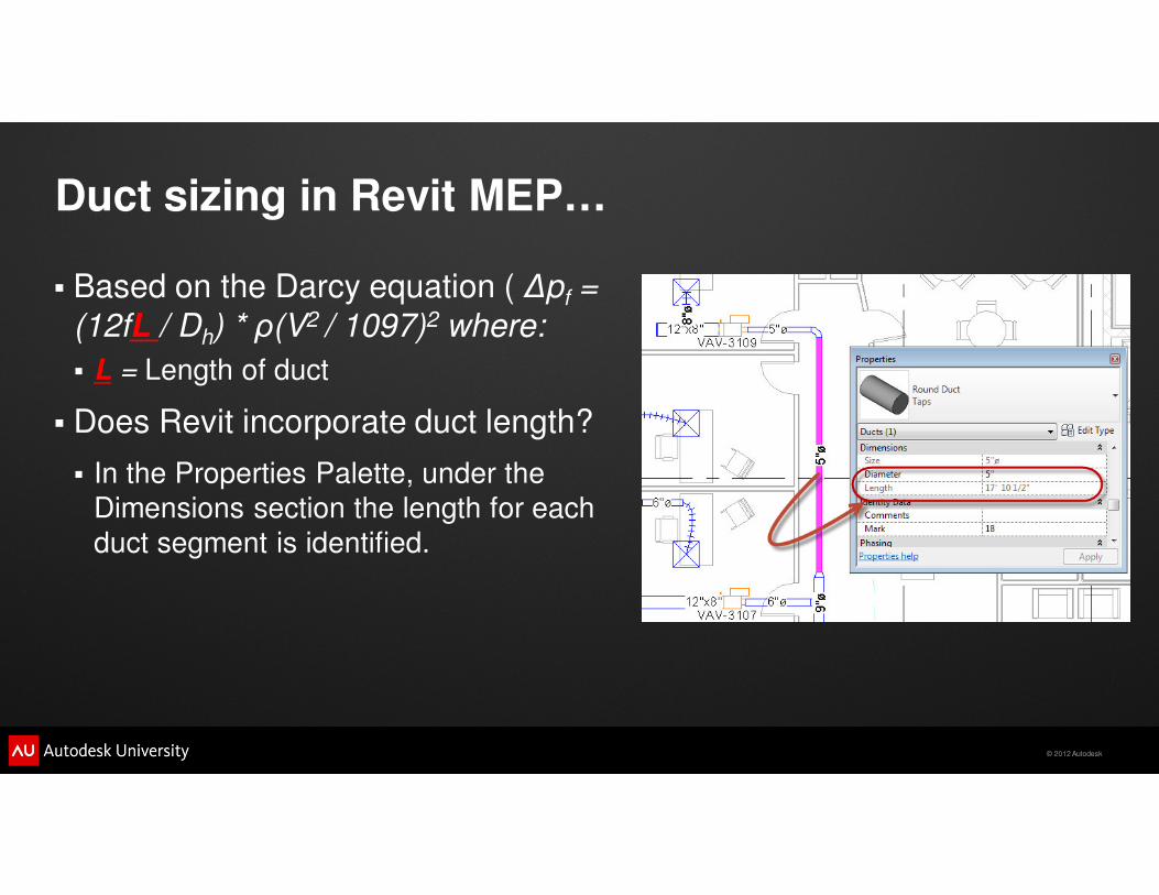
Duct sizing in Revit MEP…
� Based on the Darcy equation ( ∆pf =
(12fL / Dh) * ρ(V2 / 1097)2 where:
� L = Length of duct
� Does Revit incorporate duct length?
� In the Properties Palette, under the
Dimensions section the length for each
duct segment is identified.
© 2012 Autodesk
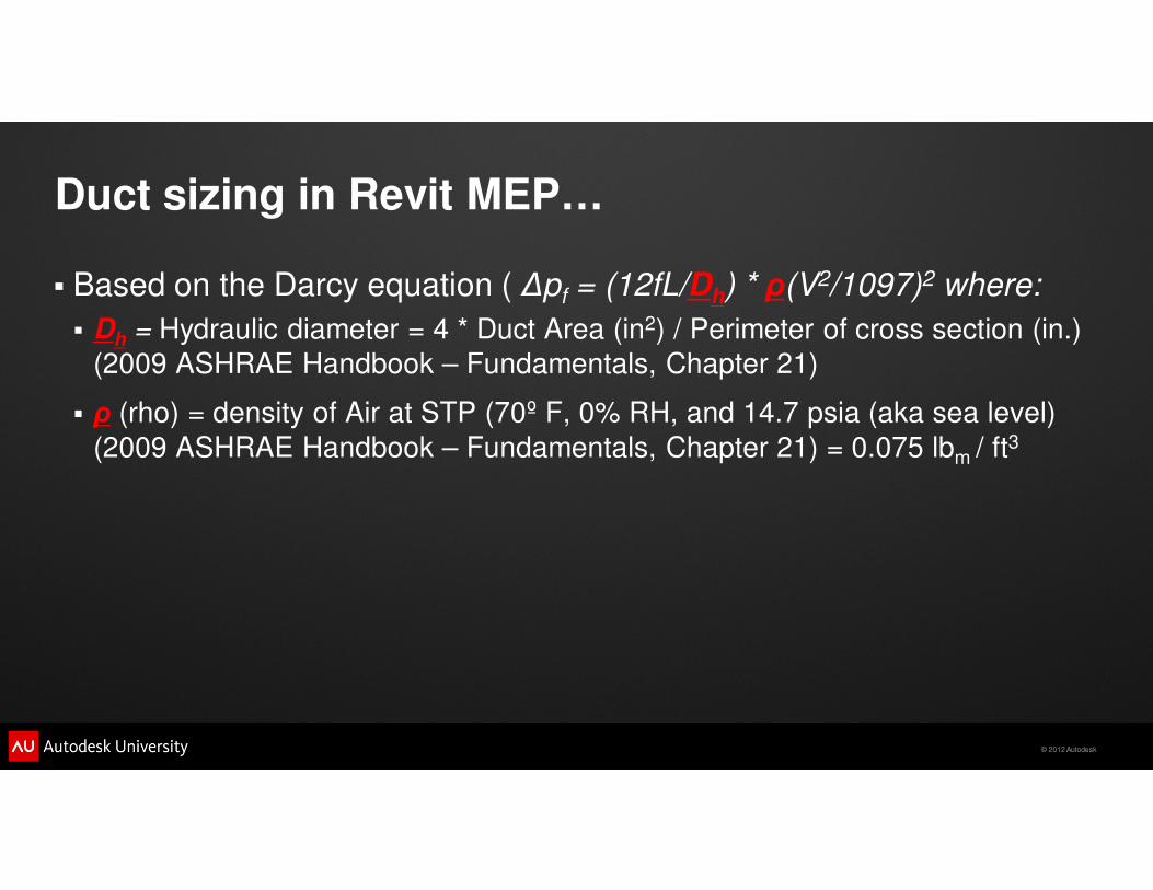
Duct sizing in Revit MEP…
� Based on the Darcy equation ( ∆pf = (12fL/Dh) * ρ(V2/1097)2 where:
� Dh = Hydraulic diameter = 4 * Duct Area (in2) / Perimeter of cross section (in.)
(2009 ASHRAE Handbook – Fundamentals, Chapter 21)
� ρ (rho) = density of Air at STP (70º F, 0% RH, and 14.7 psia (aka sea level)
(2009 ASHRAE Handbook – Fundamentals, Chapter 21) = 0.075 lbm / ft3
© 2012 Autodesk
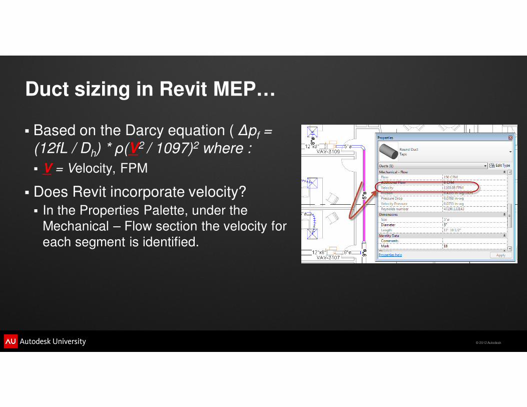
Duct sizing in Revit MEP…
� Based on the Darcy equation ( ∆pf =
(12fL / Dh) * ρ(V2 / 1097)2 where :
� V = Velocity, FPM
� Does Revit incorporate velocity?
� In the Properties Palette, under the
Mechanical – Flow section the velocity for
each segment is identified.
© 2012 Autodesk
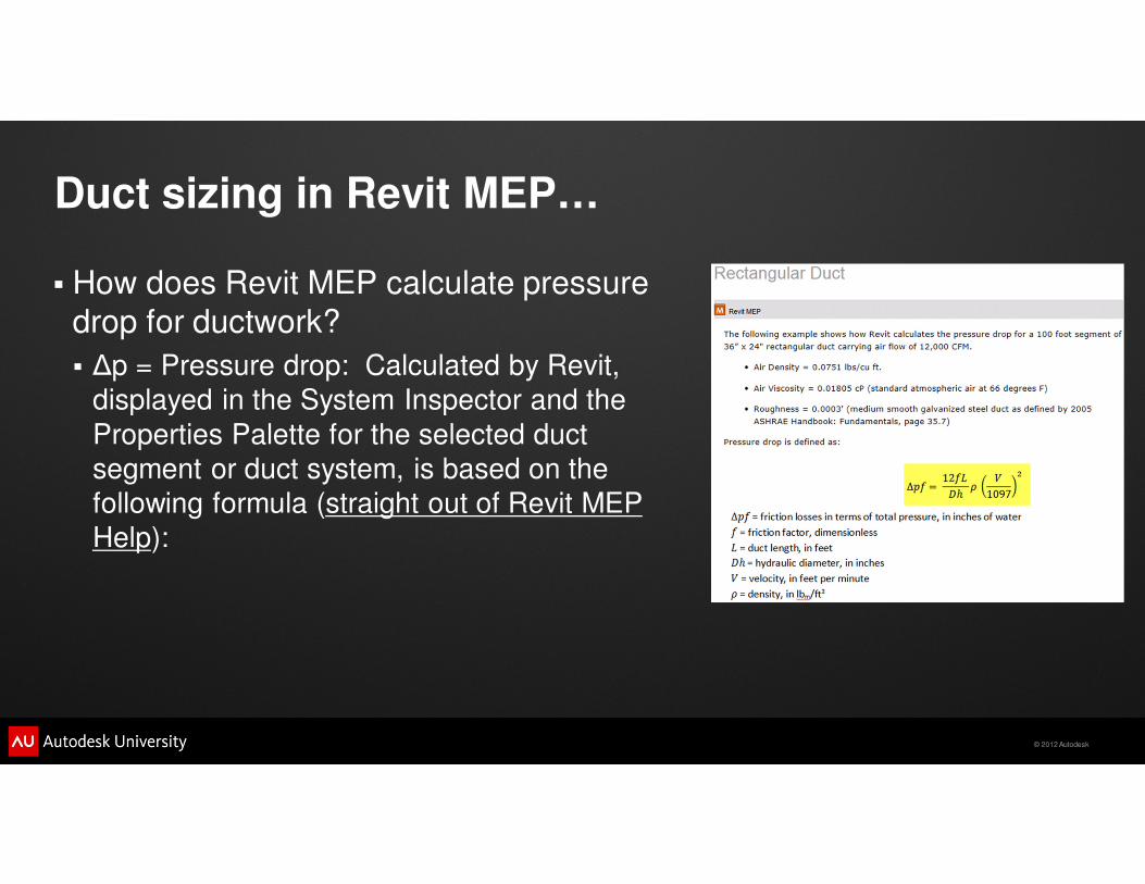
Duct sizing in Revit MEP…
� How does Revit MEP calculate pressure
drop for ductwork?
� ∆p = Pressure drop: Calculated by Revit,
displayed in the System Inspector and the
Properties Palette for the selected duct
segment or duct system, is based on the
following formula (straight out of Revit MEP
Help):
© 2012 Autodesk
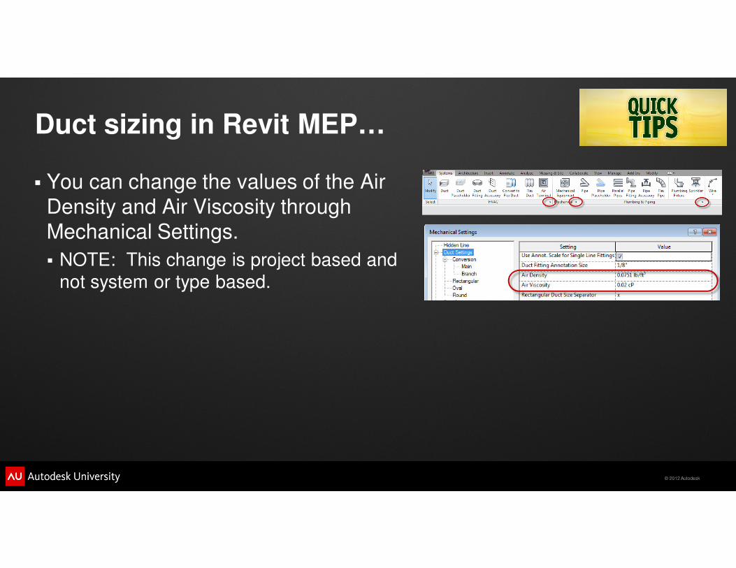
Duct sizing in Revit MEP…
� You can change the values of the Air
Density and Air Viscosity through
Mechanical Settings.
� NOTE: This change is project based and
not system or type based.
© 2012 Autodesk

© 2012 Autodesk
Class Agenda
� Introductions…
� Housekeeping items…
� A potential training resource for your efforts…
� What is an engineer?
� Ductwork calculations…
� Piping calculations…
� Helpful tips…
� Duct and Pipe tools…
� Questions…

© 2012 Autodesk
Piping Agenda
� How do you size your piping systems?
� Pipe sizing in Revit MEP…

© 2012 Autodesk
How do you size your piping systems?
© 2012 Autodesk
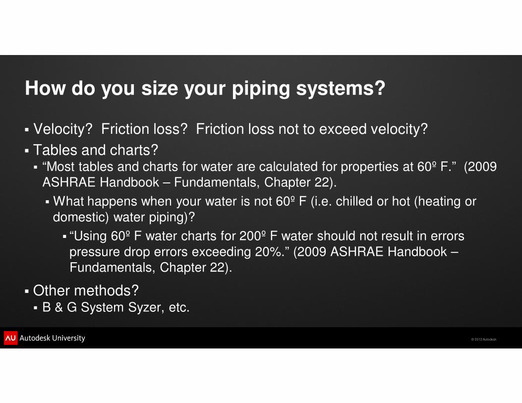
How do you size your piping systems?
� Velocity? Friction loss? Friction loss not to exceed velocity?
� Tables and charts?� “Most tables and charts for water are calculated for properties at 60º F.” (2009
ASHRAE Handbook – Fundamentals, Chapter 22).
� What happens when your water is not 60º F (i.e. chilled or hot (heating or
domestic) water piping)?
� “Using 60º F water charts for 200º F water should not result in errors
pressure drop errors exceeding 20%.” (2009 ASHRAE Handbook –
Fundamentals, Chapter 22).
� Other methods?� B & G System Syzer, etc.
© 2012 Autodesk
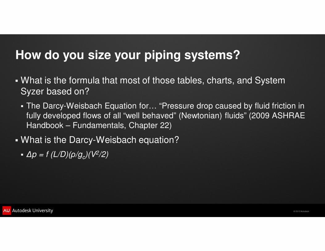
How do you size your piping systems?
� What is the formula that most of those tables, charts, and System
Syzer based on?
� The Darcy-Weisbach Equation for… “Pressure drop caused by fluid friction in
fully developed flows of all “well behaved” (Newtonian) fluids” (2009 ASHRAE
Handbook – Fundamentals, Chapter 22)
� What is the Darcy-Weisbach equation?
� ∆p = f (L/D)(ρ/gc)(V2/2)

© 2012 Autodesk
Pipe Sizing in Revit MEP
© 2012 Autodesk
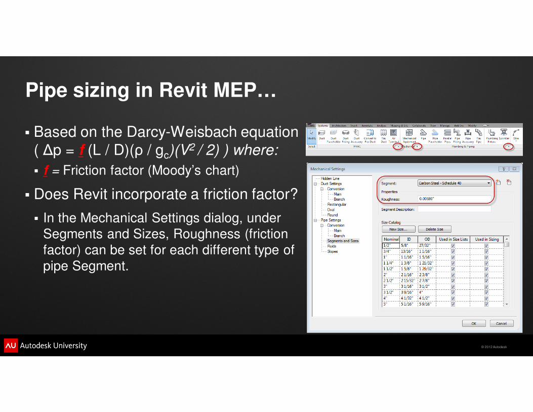
Pipe sizing in Revit MEP…
� Based on the Darcy-Weisbach equation
( ∆p = f (L / D)(ρ / gc)(V2 / 2) ) where:
� f = Friction factor (Moody’s chart)
� Does Revit incorporate a friction factor?
� In the Mechanical Settings dialog, under
Segments and Sizes, Roughness (friction
factor) can be set for each different type of
pipe Segment.
© 2012 Autodesk
Pipe sizing in Revit MEP…
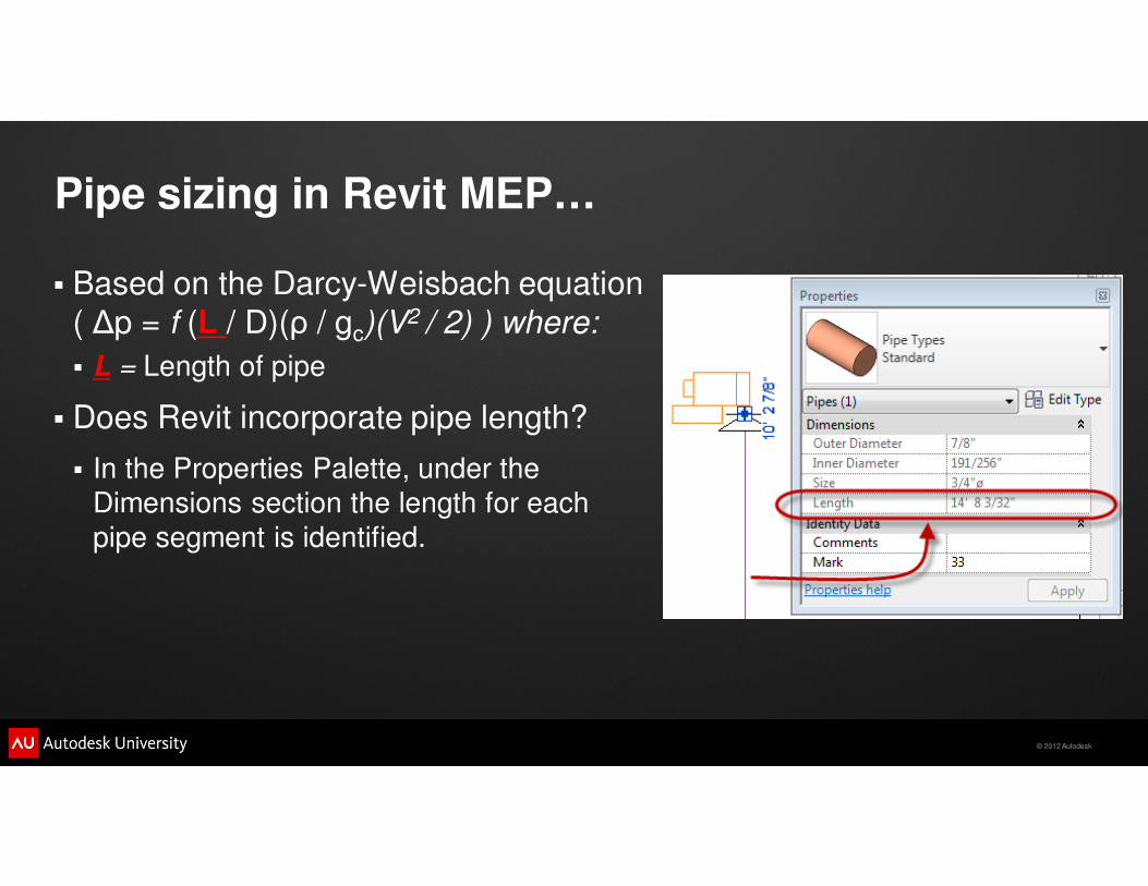
� Based on the Darcy-Weisbach equation
( ∆p = f (L / D)(ρ / gc)(V2 / 2) ) where:
� L = Length of pipe
� Does Revit incorporate pipe length?
� In the Properties Palette, under the
Dimensions section the length for each
pipe segment is identified.
© 2012 Autodesk
Pipe sizing in Revit MEP…
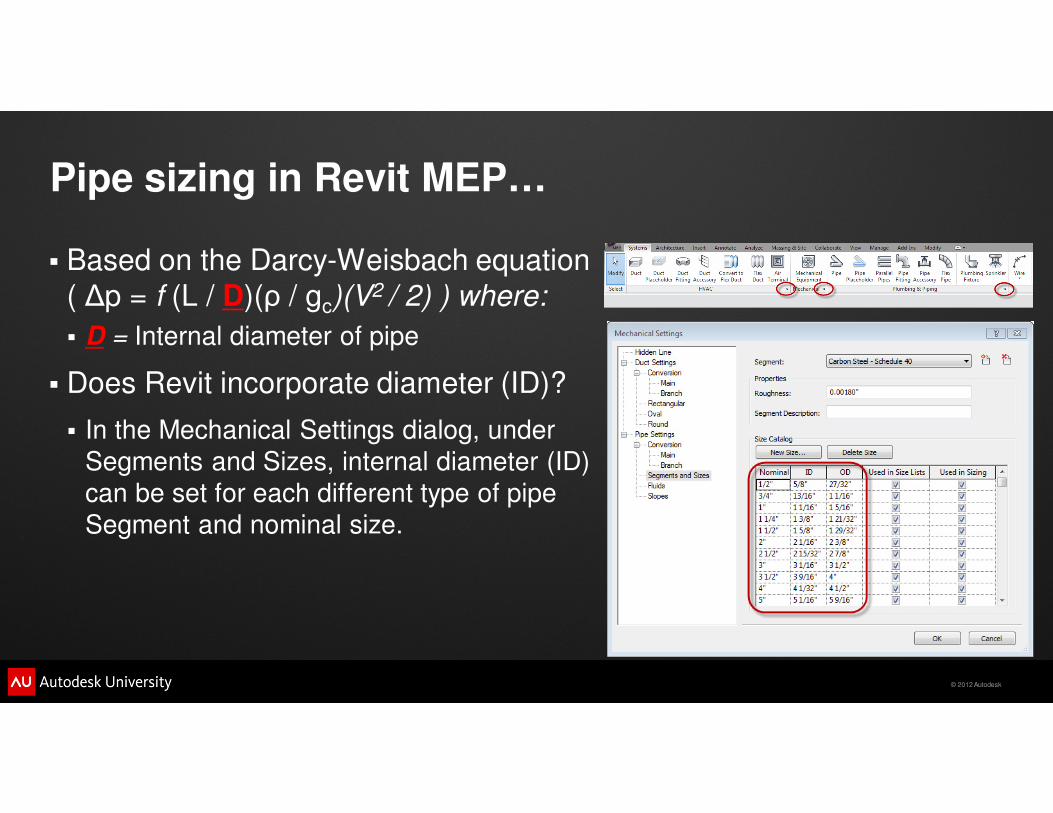
� Based on the Darcy-Weisbach equation
( ∆p = f (L / D)(ρ / gc)(V2 / 2) ) where:
� D = Internal diameter of pipe
� Does Revit incorporate diameter (ID)?
� In the Mechanical Settings dialog, under
Segments and Sizes, internal diameter (ID)
can be set for each different type of pipe
Segment and nominal size.
© 2012 Autodesk
Pipe sizing in Revit MEP…
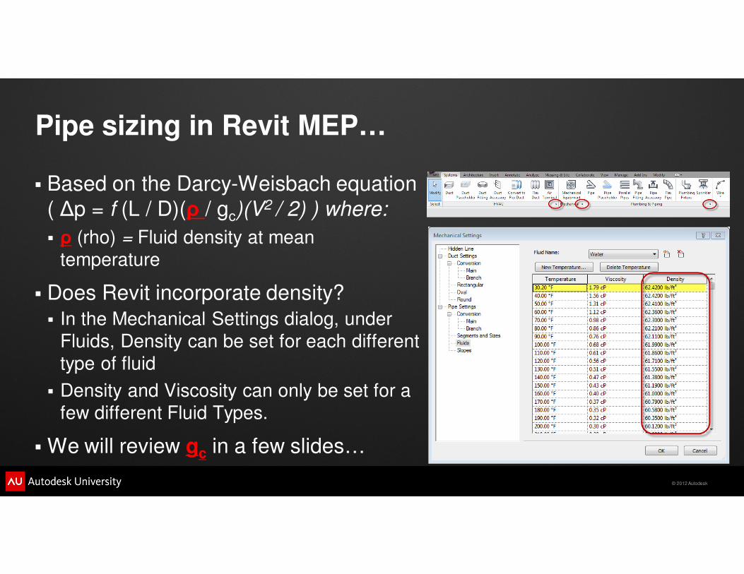
� Based on the Darcy-Weisbach equation
( ∆p = f (L / D)(ρ / gc)(V2 / 2) ) where:
� ρ (rho) = Fluid density at mean
temperature
� Does Revit incorporate density?
� In the Mechanical Settings dialog, under
Fluids, Density can be set for each different
type of fluid
� Density and Viscosity can only be set for a
few different Fluid Types.
� We will review gc in a few slides…
© 2012 Autodesk
Pipe sizing in Revit MEP…
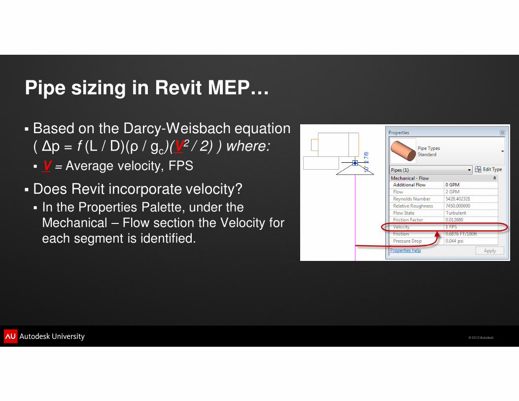
� Based on the Darcy-Weisbach equation
( ∆p = f (L / D)(ρ / gc)(V2 / 2) ) where:
� V = Average velocity, FPS
� Does Revit incorporate velocity?
� In the Properties Palette, under the
Mechanical – Flow section the Velocity for
each segment is identified.
© 2012 Autodesk
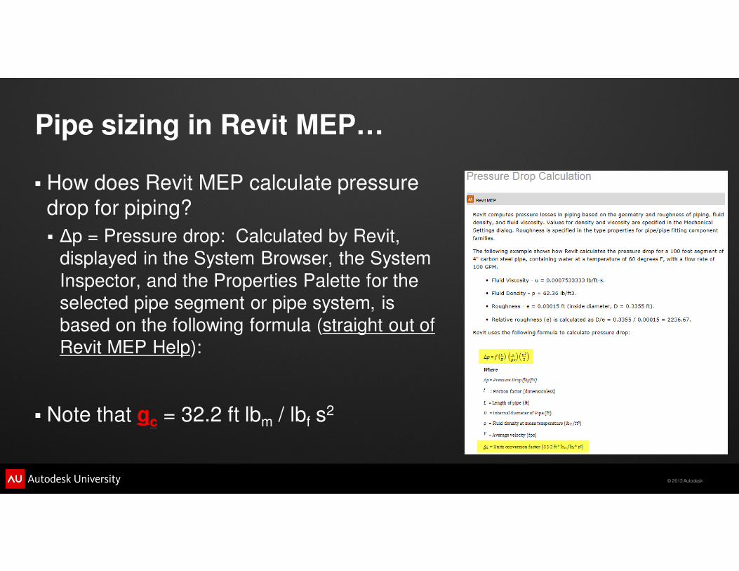
Pipe sizing in Revit MEP…
� How does Revit MEP calculate pressure
drop for piping?
� ∆p = Pressure drop: Calculated by Revit,
displayed in the System Browser, the System
Inspector, and the Properties Palette for the
selected pipe segment or pipe system, is
based on the following formula (straight out of
Revit MEP Help):
� Note that gc = 32.2 ft lbm / lbf s2
© 2012 Autodesk
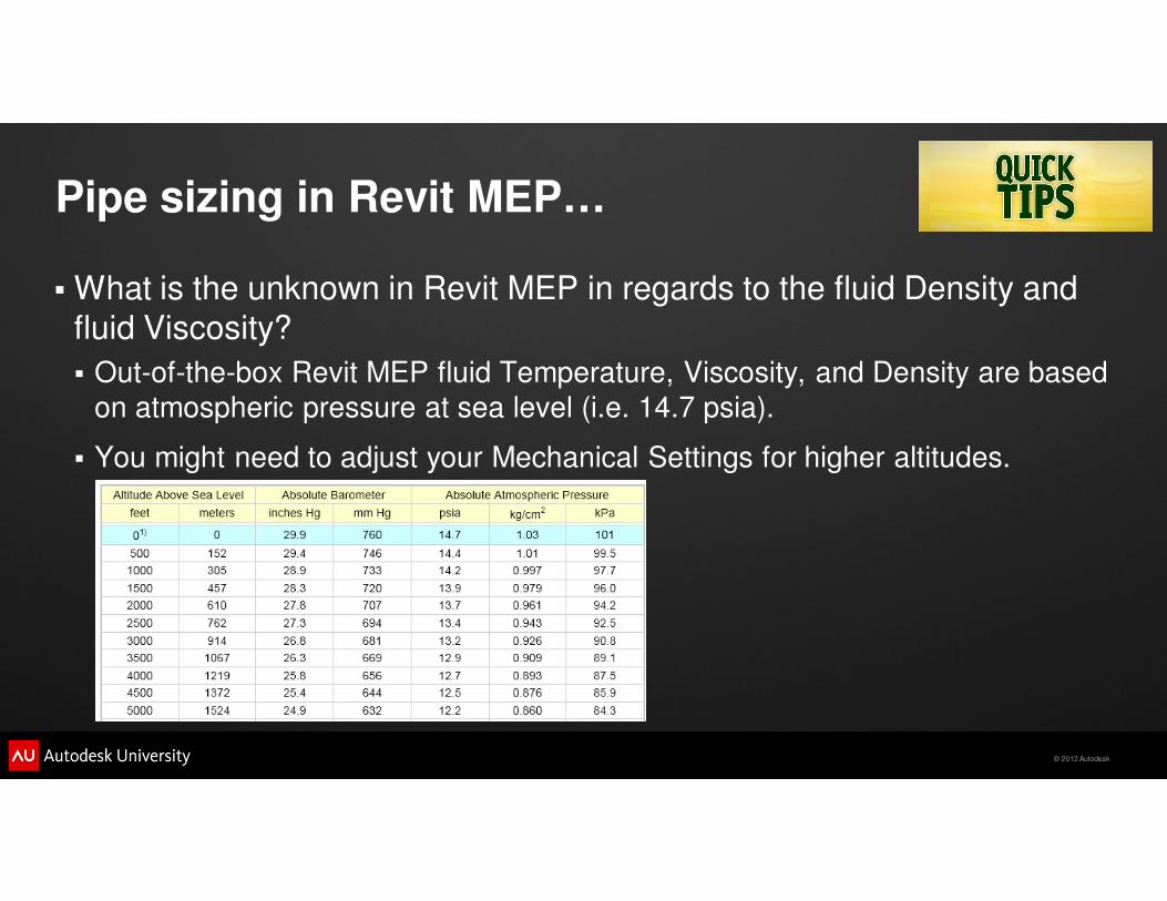
Pipe sizing in Revit MEP…
� What is the unknown in Revit MEP in regards to the fluid Density and
fluid Viscosity?
� Out-of-the-box Revit MEP fluid Temperature, Viscosity, and Density are based
on atmospheric pressure at sea level (i.e. 14.7 psia).
� You might need to adjust your Mechanical Settings for higher altitudes.

© 2012 Autodesk

© 2012 Autodesk
Class Agenda
� Introductions…
� Housekeeping items…
� A potential training resource for your efforts…
� What is an engineer?
� Ductwork calculations…
� Piping calculations…
� Helpful tips…
� Duct and Pipe tools…
� Questions…
© 2012 Autodesk
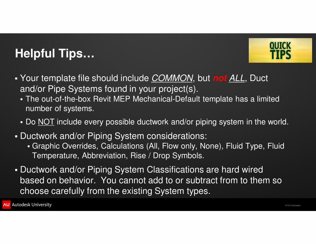
Helpful Tips…
� Your template file should include COMMON, but not ALL, Duct
and/or Pipe Systems found in your project(s).� The out-of-the-box Revit MEP Mechanical-Default template has a limited
number of systems.
� Do NOT include every possible ductwork and/or piping system in the world.
� Ductwork and/or Piping System considerations:� Graphic Overrides, Calculations (All, Flow only, None), Fluid Type, Fluid
Temperature, Abbreviation, Rise / Drop Symbols.
� Ductwork and/or Piping System Classifications are hard wired
based on behavior. You cannot add to or subtract from to them so choose carefully from the existing System types.
© 2012 Autodesk
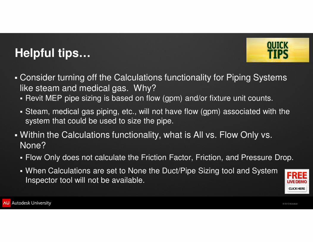
Helpful tips…
� Consider turning off the Calculations functionality for Piping Systems
like steam and medical gas. Why?� Revit MEP pipe sizing is based on flow (gpm) and/or fixture unit counts.
� Steam, medical gas piping, etc., will not have flow (gpm) associated with the
system that could be used to size the pipe.
� Within the Calculations functionality, what is All vs. Flow Only vs. None?
� Flow Only does not calculate the Friction Factor, Friction, and Pressure Drop.
� When Calculations are set to None the Duct/Pipe Sizing tool and System
Inspector tool will not be available.
© 2012 Autodesk
Helpful tips…
� Items to pay attention to in your Duct and/or Pipe system layout…
� Disconnects → This creates Warnings, Warnings lead to poor model
performance, poor model performance leads to frustrated users and
contributes to less project profitability.
� Stray Duct/Pipe → This leads to unnecessary System creation which leads to
poor model performance, poor model performance leads to frustrated users
and contributes to less project profitability.
� Open ended or uncapped Duct/Pipe → This creates Warnings, Warnings lead
to poor model performance, poor model performance leads to frustrated users
and contributes to less project profitability.
© 2012 Autodesk
Helpful tips…
� Items to pay attention to in your Duct and/or Pipe system layout…
� Loss Definitions → This creates Warnings, Warnings lead to poor model
performance, poor model performance leads to frustrated users and
contributes to less project profitability.
� Systems → Too many systems lead to poor model performance, poor model
performance leads to frustrated users and contributes to less project
profitability.
� Assign flows → Without the appropriate flows assign to your Families your
Duct and Pipe tools might not perform as expected.
© 2012 Autodesk
Helpful tips…
� Tools you should rely on with your Duct and/or Pipe system layout…
� Warnings → Take them seriously and attempt to address all of them. If your
Service Engine Soon warning light came on would you drive another 1,000
miles? Use Select by ID to help find the Warnings if Show will not work to
your advantage.
� Show Disconnects → This helps visually identify any disconnected Duct or
Piping helping you to reduce or eliminate Warnings.
� Check Duct/Pipe System → Web lines will indicate where there are potential
failures in your system.
© 2012 Autodesk

© 2012 Autodesk
Class Agenda
� Introductions…
� Housekeeping items…
� A potential training resource for your efforts…
� What is an engineer?
� Ductwork calculations…
� Piping calculations…
� Helpful tips…
� Duct and Pipe tools…
� Questions…
© 2012 Autodesk
Duct and Pipe tools…
� Duct/Pipe Size tool > Select a sizing method for your duct/pipe
system and let Revit MEP do the “heavy lifting” by sizing your
duct/pipe system based on the values you input.
� Duct/Pipe Pressure Loss Report > Evaluate your system’s total pressure loss and gain understanding of the system’s critical path
after your duct/pipe system has been sized.
� System Inspector > Gain a better understanding of the connected flows in your system and their losses.
� Color Legend > Visually highlight critical areas of your design that
might need to be re-evaluated.
© 2012 Autodesk
Class Summary (Recap)
We focused on ductwork and piping and their related tools in an effort to
help you better understand and facilitate your design through the analysis
of your ductwork and piping systems. We explored:
� Calculation fundamentals for both ductwork and piping and learned how they are incorporated in Revit MEP as well as the impacts they have on
sizing your ductwork and piping systems.
� Tools for routing and sizing your ductwork and piping systems.
� The System Inspector and how it can supplement the Duct and Pipe
Pressure Loss Reports.
� Added color to your ductwork and piping analysis with Legends and Fills.

© 2012 Autodesk

© 2012 Autodesk
Questions

© 2012 Autodesk
Autodesk, AutoCAD* [*if/when mentioned in the pertinent material, followed by an alphabetical list of all other trademarks mentioned in the material] are registered trademarks or trademarks of Autodesk, Inc., and/or its subsidiaries and/or affiliates in the USA and/or other countries. All other brand names, product names, or trademarks belong to their respective holders. Autodesk reserves the right to alter product and services offerings, and specifications and pricing at any time without notice, and is not responsible for typographical or graphical errors that may appear in this document. © 2012 Autodesk, Inc. All rights reserved.