mpls ex series provider edge switches configuring cli
TRANSCRIPT
5/12/2018 Mpls Ex Series Provider Edge Switches Configuring Cli - slidepdf.com
http://slidepdf.com/reader/full/mpls-ex-series-provider-edge-switches-configuring-cli
Configuring MPLS on Provider Edge Switches (CLI Procedure)
JUNOS MPLS for EX Series switches supports Layer 2 protocols and Layer 2 virtualprivate networks (VPNs). You can configure MPLS on your switches to increasetransport efficiency in your network. MPLS services can be used to connect varioussites to a backbone network or to ensure better performance for low-latencyapplications such as VoIP and other business-critical functions.
To implement MPLS on EX Series switches, you must configure two provider edgeswitches: an ingress provider edge switch and an egress provider edge switch.
To configure a provider edge switch, complete the following tasks. When you havecompleted configuring one provider edge switch, perform the same tasks on theother provider edge switch:
1. Enabling the OSPF or the IS-IS Routing Protocol on the Loopback and Core
Interfaces on page 1
2. Enabling Traffic Engineering for the Routing Protocol on page 2
3. Configuring IP Addresses for the Loopback and Core Interfaces on page 2
4. Enabling MPLS, Defining the Label Switched Path, and Applying MPLS to theCore Interfaces on page 2
5. Enabling RSVP and Applying It to the Loopback and Core Interfaces on page 3
6. Enabling Family MPLS on the Core Interfaces on page 4
7. Configuring a Circuit Cross-Connect on a Customer Edge Interface on page 4
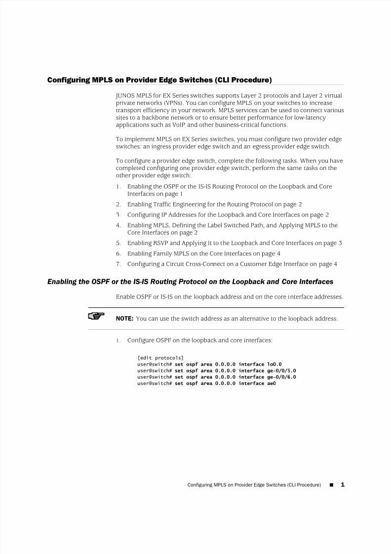
Enabling the OSPF or the IS-IS Routing Protocol on the Loopback and Core Interfaces
Enable OSPF or IS-IS on the loopback address and on the core interface addresses.
NOTE: You can use the switch address as an alternative to the loopback address.
1. Configure OSPF on the loopback and core interfaces:
[edit protocols]
user@switch# set ospf area 0.0.0.0 interface lo0.0
user@switch# set ospf area 0.0.0.0 interface ge-0/0/5.0
user@switch# set ospf area 0.0.0.0 interface ge-0/0/6.0
user@switch# set ospf area 0.0.0.0 interface ae0
Configuring MPLS on Provider Edge Switches (CLI Procedure) ■ 1
5/12/2018 Mpls Ex Series Provider Edge Switches Configuring Cli - slidepdf.com
http://slidepdf.com/reader/full/mpls-ex-series-provider-edge-switches-configuring-cli
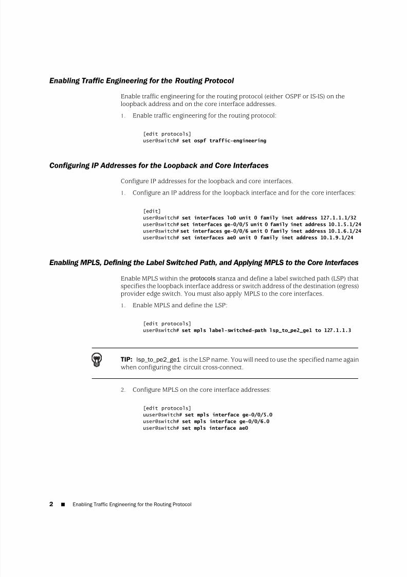
Enabling Traffic Engineering for the Routing Protocol
Enable traffic engineering for the routing protocol (either OSPF or IS-IS) on theloopback address and on the core interface addresses.
1. Enable traffic engineering for the routing protocol:
[edit protocols]
user@switch# set ospf traffic-engineering
Configuring IP Addresses for the Loopback and Core Interfaces
Configure IP addresses for the loopback and core interfaces.
1. Configure an IP address for the loopback interface and for the core interfaces:
[edit]
user@switch# set interfaces lo0 unit 0 family inet address 127.1.1.1/32
user@switch# set interfaces ge-0/0/5 unit 0 family inet address 10.1.5.1/24
user@switch# set interfaces ge-0/0/6 unit 0 family inet address 10.1.6.1/24
user@switch# set interfaces ae0 unit 0 family inet address 10.1.9.1/24
Enabling MPLS, Defining the Label Switched Path, and Applying MPLS to the Core Interfaces
Enable MPLS within the protocols stanza and define a label switched path (LSP) thatspecifies the loopback interface address or switch address of the destination (egress)provider edge switch. You must also apply MPLS to the core interfaces.
1. Enable MPLS and define the LSP:
[edit protocols]
user@switch# set mpls label-switched-path lsp_to_pe2_ge1 to 127.1.1.3
TIP: lsp_to_pe2_ge1 is the LSP name. You will need to use the specified name againwhen configuring the circuit cross-connect.
2. Configure MPLS on the core interface addresses:
[edit protocols]
uuser@switch# set mpls interface ge-0/0/5.0
user@switch# set mpls interface ge-0/0/6.0
user@switch# set mpls interface ae0
2 ■ Enabling Traffic Engineering for the Routing Protocol
5/12/2018 Mpls Ex Series Provider Edge Switches Configuring Cli - slidepdf.com
http://slidepdf.com/reader/full/mpls-ex-series-provider-edge-switches-configuring-cli
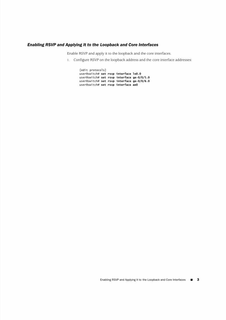
Enabling RSVP and Applying It to the Loopback and Core Interfaces
Enable RSVP and apply it to the loopback and the core interfaces.
1. Configure RSVP on the loopback address and the core interface addresses:
[edit protocols]
user@switch# set rsvp interface lo0.0
user@switch# set rsvp interface ge-0/0/5.0
user@switch# set rsvp interface ge-0/0/6.0
user@switch# set rsvp interface ae0
Enabling RSVP and Applying It to the Loopback and Core Interfaces ■ 3
5/12/2018 Mpls Ex Series Provider Edge Switches Configuring Cli - slidepdf.com
http://slidepdf.com/reader/full/mpls-ex-series-provider-edge-switches-configuring-cli
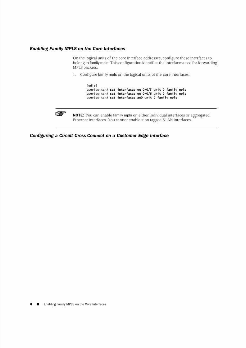
Enabling Family MPLS on the Core Interfaces
On the logical units of the core interface addresses, configure these interfaces tobelong to family mpls. This configuration identifies the interfaces used for forwardingMPLS packets.
1. Configure family mpls on the logical units of the core interfaces:
[edit]
user@switch# set interfaces ge-0/0/5 unit 0 family mpls
user@switch# set interfaces ge-0/0/6 unit 0 family mpls
user@switch# set interfaces ae0 unit 0 family mpls
NOTE: You can enable family mpls on either individual interfaces or aggregated
Ethernet interfaces. You cannot enable it on tagged VLAN interfaces.
Configuring a Circuit Cross-Connect on a Customer Edge Interface
4 ■ Enabling Family MPLS on the Core Interfaces
5/12/2018 Mpls Ex Series Provider Edge Switches Configuring Cli - slidepdf.com
http://slidepdf.com/reader/full/mpls-ex-series-provider-edge-switches-configuring-cli
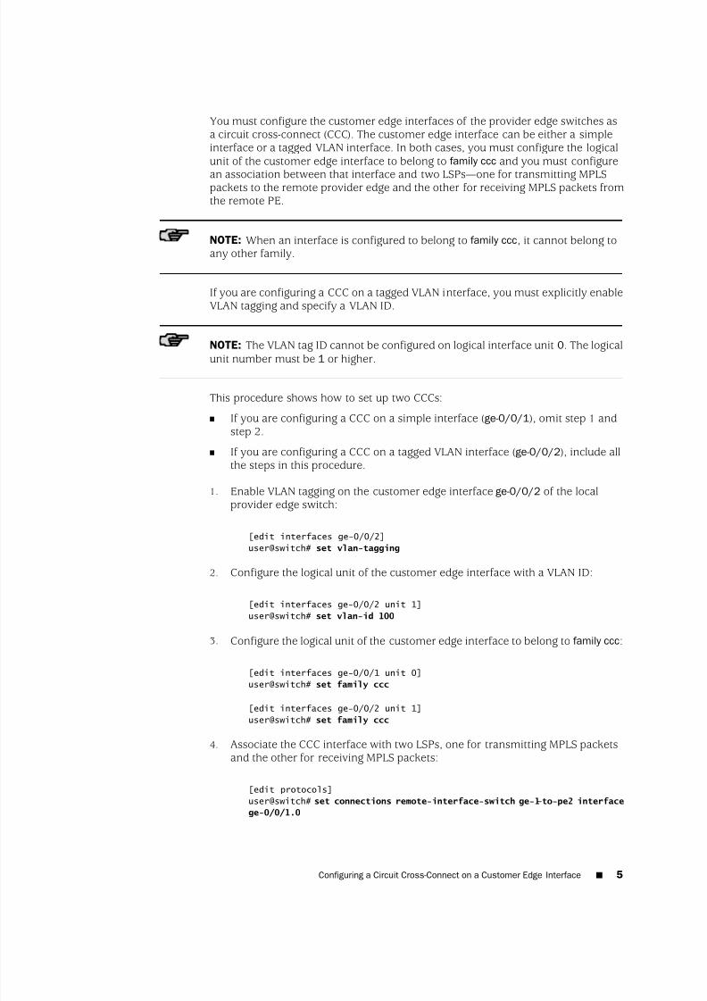
You must configure the customer edge interfaces of the provider edge switches asa circuit cross-connect (CCC). The customer edge interface can be either a simpleinterface or a tagged VLAN interface. In both cases, you must configure the logicalunit of the customer edge interface to belong to family ccc and you must configure
an association between that interface and two LSPs—
one for transmitting MPLSpackets to the remote provider edge and the other for receiving MPLS packets fromthe remote PE.
NOTE: When an interface is configured to belong to family ccc, it cannot belong toany other family.
If you are configuring a CCC on a tagged VLAN interface, you must explicitly enableVLAN tagging and specify a VLAN ID.
NOTE: The VLAN tag ID cannot be configured on logical interface unit 0. The logicalunit number must be 1 or higher.
This procedure shows how to set up two CCCs:
■ If you are configuring a CCC on a simple interface (ge-0/0/1), omit step 1 andstep 2.
■ If you are configuring a CCC on a tagged VLAN interface (ge-0/0/2), include allthe steps in this procedure.
1. Enable VLAN tagging on the customer edge interface ge-0/0/2 of the localprovider edge switch:
[edit interfaces ge-0/0/2]
user@switch# set vlan-tagging
2. Configure the logical unit of the customer edge interface with a VLAN ID:
[edit interfaces ge-0/0/2 unit 1]
user@switch# set vlan-id 100
3. Configure the logical unit of the customer edge interface to belong to family ccc:
[edit interfaces ge-0/0/1 unit 0]
user@switch# set family ccc
[edit interfaces ge-0/0/2 unit 1]
user@switch# set family ccc
4. Associate the CCC interface with two LSPs, one for transmitting MPLS packetsand the other for receiving MPLS packets:
[edit protocols]
user@switch# set connections remote-interface-switch ge-1–to-pe2 interface
ge-0/0/1.0
Configuring a Circuit Cross-Connect on a Customer Edge Interface ■ 5
5/12/2018 Mpls Ex Series Provider Edge Switches Configuring Cli - slidepdf.com
http://slidepdf.com/reader/full/mpls-ex-series-provider-edge-switches-configuring-cli
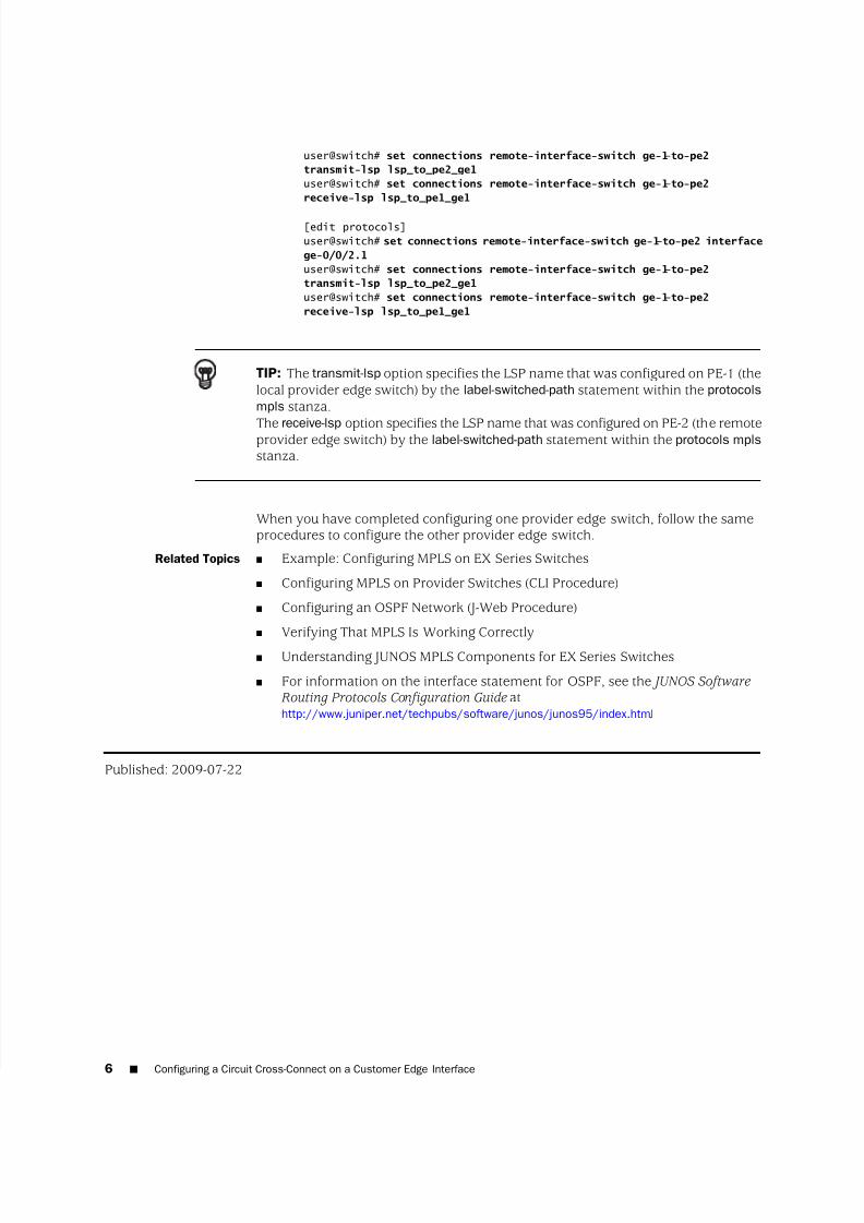
user@switch# set connections remote-interface-switch ge-1–to-pe2
transmit-lsp lsp_to_pe2_ge1
user@switch# set connections remote-interface-switch ge-1–to-pe2
receive-lsp lsp_to_pe1_ge1
[edit protocols]
user@switch# set connections remote-interface-switch ge-1–to-pe2 interface
ge-0/0/2.1
user@switch# set connections remote-interface-switch ge-1–to-pe2
transmit-lsp lsp_to_pe2_ge1
user@switch# set connections remote-interface-switch ge-1–to-pe2
receive-lsp lsp_to_pe1_ge1
TIP: The transmit-lsp option specifies the LSP name that was configured on PE-1 (thelocal provider edge switch) by the label-switched-path statement within the protocols
mpls stanza.
The receive-lsp option specifies the LSP name that was configured on PE-2 (the remoteprovider edge switch) by the label-switched-path statement within the protocols mpls
stanza.
When you have completed configuring one provider edge switch, follow the sameprocedures to configure the other provider edge switch.
Related Topics ■ Example: Configuring MPLS on EX Series Switches
■ Configuring MPLS on Provider Switches (CLI Procedure)
■ Configuring an OSPF Network (J-Web Procedure)
■ Verifying That MPLS Is Working Correctly
■ Understanding JUNOS MPLS Components for EX Series Switches
■ For information on the interface statement for OSPF, see the JUNOS Software Routing Protocols Configuration Guide athttp://www.juniper.net/techpubs/software/junos/junos95/index.html.
Published: 2009-07-22
6 ■ Configuring a Circuit Cross-Connect on a Customer Edge Interface