mppc radiation hardness (gamma-ray & neutron)
DESCRIPTION
MPPC Radiation Hardness (gamma-ray & neutron). Satoru Uozumi , Kobe University for Toshinori Ikuno, Hideki Yamazaki, and all the ScECAL group. Knowing radiation resistivity is important to estimate the life time of the calorimeter under the environment at the ILC. - PowerPoint PPT PresentationTRANSCRIPT
MPPC Radiation Hardness(gamma-ray & neutron)
Satoru Uozumi, Kobe University for Toshinori Ikuno, Hideki Yamazaki,
and all the ScECAL group
Knowing radiation resistivity is important to estimate the life time of the calorimeter under the environment at the ILC.In last year we have some chances to have radiation test with gamma-ray and neutrons.
Multi Pixel Photon Counter (MPPC)
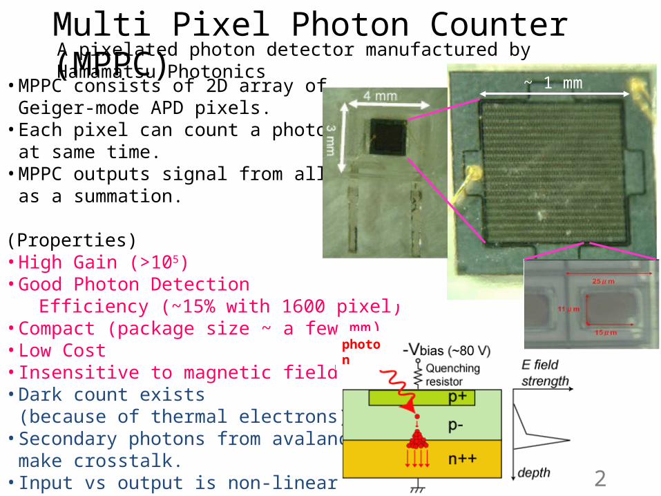
• MPPC consists of 2D array of Geiger-mode APD pixels.• Each pixel can count a photon
at same time.• MPPC outputs signal from all pixels
as a summation.
(Properties)• High Gain (>105)• Good Photon Detection Efficiency (~15% with 1600 pixel)• Compact (package size ~ a few mm)• Low Cost • Insensitive to magnetic field• Dark count exists (because of thermal electrons)• Secondary photons from avalanche
make crosstalk.• Input vs output is non-linear
photon
~ 1 mm
2
A pixelated photon detector manufactured by Hamamatsu Photonics
Gamma-ray Radiation
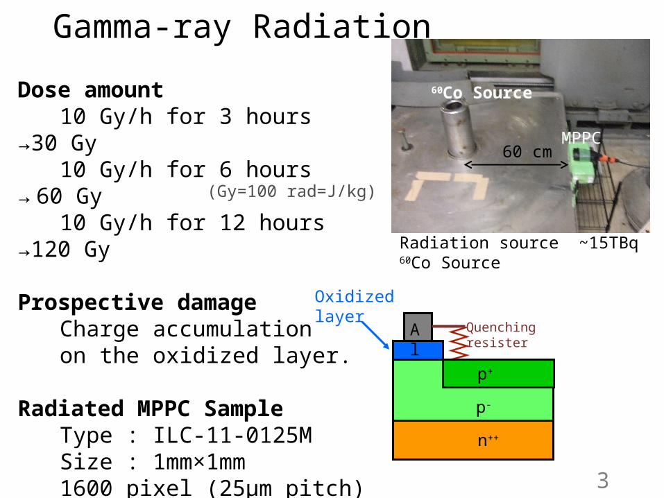
Dose amount10 Gy/h for 3 hours →30 Gy10 Gy/h for 6 hours → 60 Gy10 Gy/h for 12 hours →120 Gy
Prospective damageCharge accumulation
on the oxidized layer.
Radiated MPPC SampleType : ILC-11-0125M
Size : 1mm×1mm 1600 pixel (25μm pitch)
(Gy=100 rad=J/kg)
Radiation source ~15TBq 60Co Source
60 cmMPPC
60Co Source
Oxidizedlayer
p+
p-
n++
Quenchingresister
Al
3
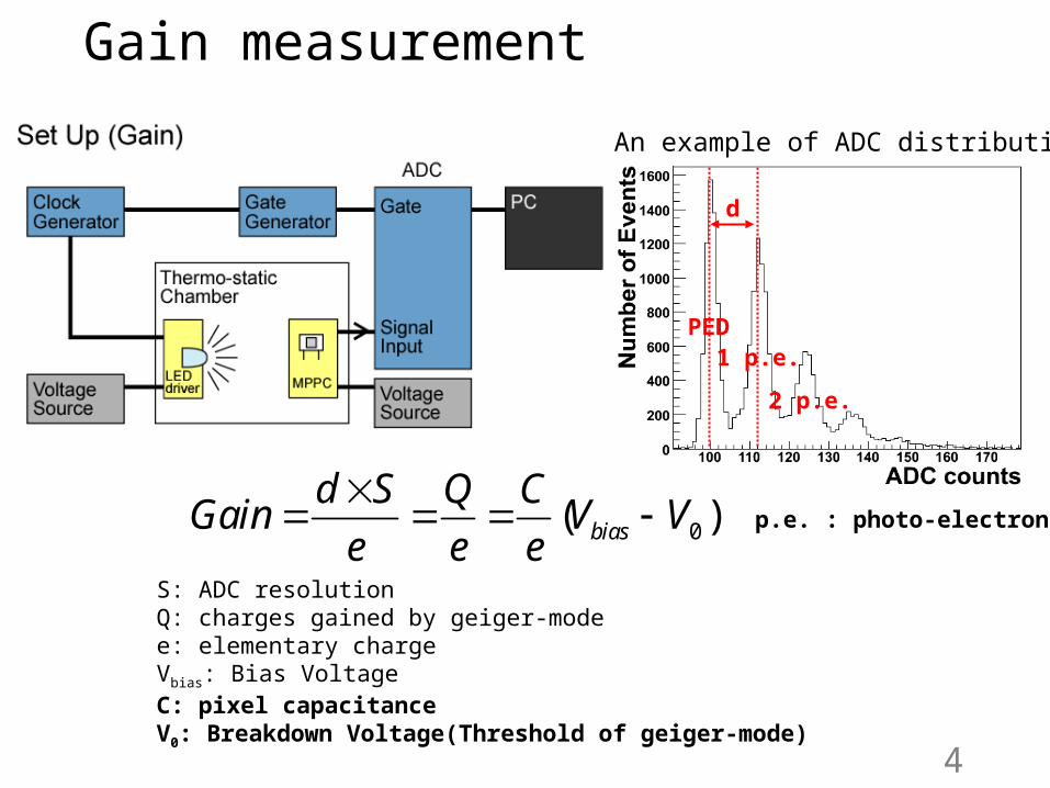
PED 1 p.e. 2 p.e.
d
Gain measurement
0( )bias
d S Q CGain V V
e e e
S: ADC resolutionQ: charges gained by geiger-modee: elementary chargeVbias: Bias VoltageC: pixel capacitanceV0: Breakdown Voltage(Threshold of geiger-mode)
4
An example of ADC distribution
PED1 p.e.
2 p.e.
p.e. : photo-electron
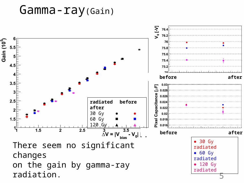
Gamma-ray(Gain)
There seem no significant changes on the gain by gamma-ray radiation.
radiated before after30 Gy ● ●60 Gy ■ ■120 Gy ▲ ▲
before after
before after
5
● 30 Gy radiated ● 60 Gy radiated ● 120 Gy radiated
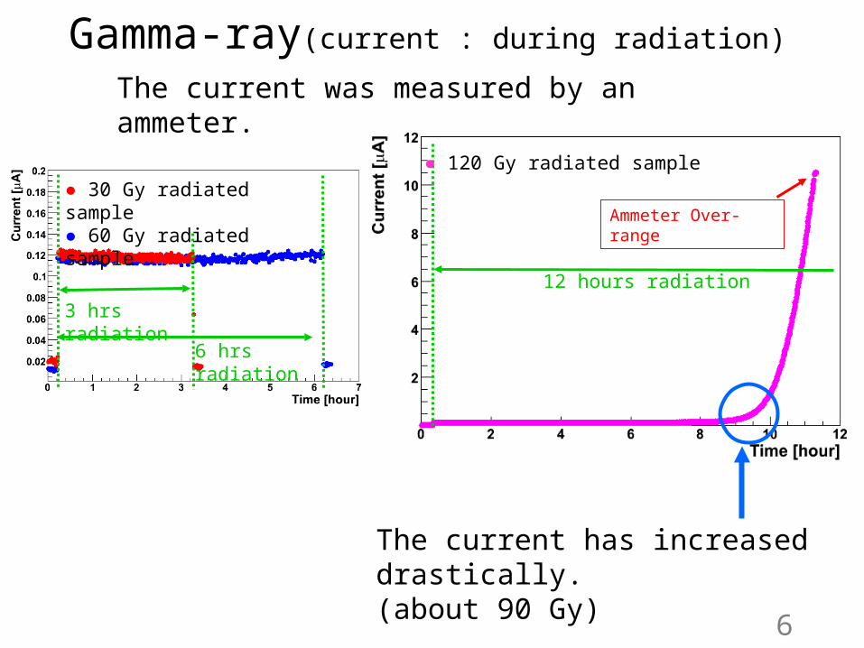
The current has increased drastically.(about 90 Gy)
3 hrs radiation
● 30 Gy radiated sample● 60 Gy radiated sample
6 hrs radiation
Gamma-ray(current : during radiation)
6
12 hours radiation
Ammeter Over-range
● 120 Gy radiated sample
The current was measured by an ammeter.
● 120 Gy radiated sample
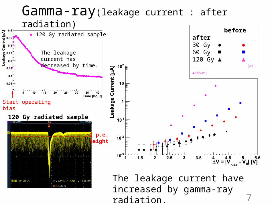
The leakage current has decreased by time.
Start operating bias
Gamma-ray(leakage current : after radiation)
before after30 Gy ● ●60 Gy ■ ■120 Gy ▲ ▲
(at 40hour)
The leakage current haveincreased by gamma-ray radiation.
7
120 Gy radiated sample
1 p.e. height
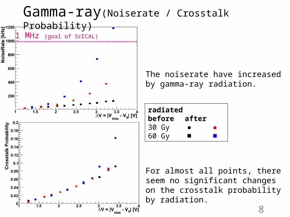
The noiserate have increased by gamma-ray radiation.
For almost all points, there seem no significant changes on the crosstalk probability by radiation.
Gamma-ray(Noiserate / Crosstalk Probability)
radiated before after30 Gy ● ●60 Gy ■ ■
1 MHz (goal of ScECAL)
8
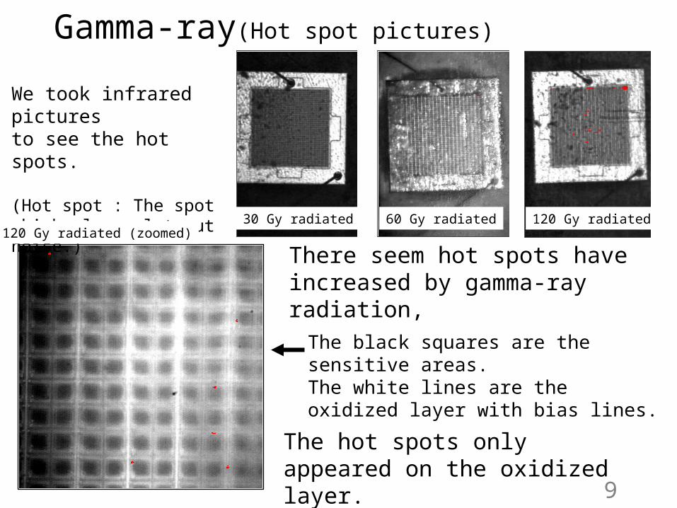
Gamma-ray(Hot spot pictures)
9
The hot spots only appeared on the oxidized layer.
The black squares are the sensitive areas.The white lines are the oxidized layer with bias lines.
30 Gy radiated 60 Gy radiated 120 Gy radiated
We took infrared picturesto see the hot spots.
(Hot spot : The spot which always let out noise.)
There seem hot spots have increased by gamma-ray radiation,
120 Gy radiated (zoomed)
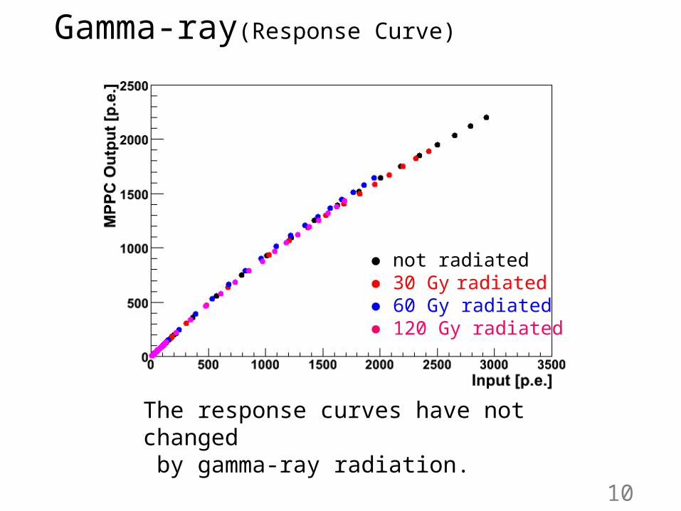
The response curves have not changed by gamma-ray radiation.
● not radiated ● 30 Gy radiated ● 60 Gy radiated ● 120 Gy radiated
Gamma-ray(Response Curve)
10
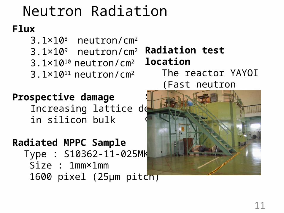
Neutron RadiationFlux
3.1×10⁸ neutron/cm2
3.1×10⁹ neutron/cm2
3.1×10¹⁰ neutron/cm2
3.1×10¹¹ neutron/cm2
Prospective damageIncreasing lattice defectin silicon bulk
Radiated MPPC Sample Type : S10362-11-025MK Size : 1mm×1mm 1600 pixel (25μm pitch)
Radiation test location The reactor YAYOI (Fast neutron source reactor of the University of Tokyo)
11

Neutron(Gain)
radiated before after108 /cm2 ● ●109 /cm2 ■ ■1010 /cm2 ▲ ▲
There seem no significant changes on the gain by neutron radiation.
before after
before after
12
● 108 /cm2 radiated ● 109 /cm2 radiated ● 1010 /cm2 radiated
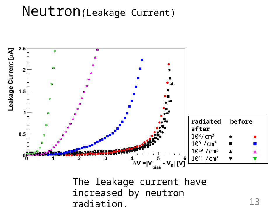
Neutron(Leakage Current)
radiated before after108/cm2 ● ●109 /cm2 ■ ■1010 /cm2 ▲ ▲1011 /cm2 ▼ ▼
The leakage current haveincreased by neutron radiation.
13
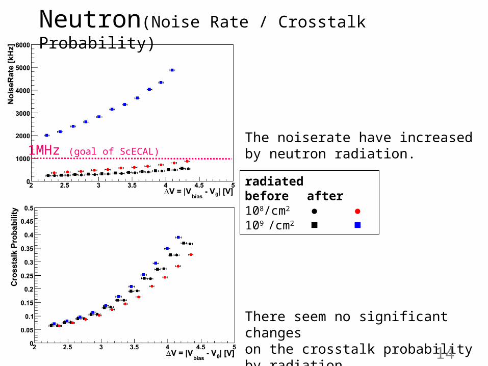
Neutron(Noise Rate / Crosstalk Probability)
The noiserate have increased by neutron radiation.
There seem no significant changeson the crosstalk probability by radiation.
radiated before after108/cm2 ● ●109 /cm2 ■ ■
1MHz (goal of ScECAL)
14
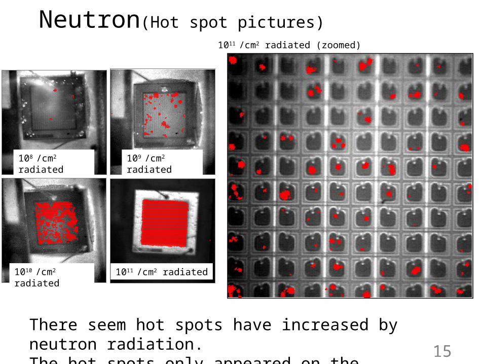
There seem hot spots have increased by neutron radiation.The hot spots only appeared on the sensitive area.
Neutron(Hot spot pictures)
15
108 /cm2 radiated 109 /cm2 radiated
1010 /cm2 radiated 1011 /cm2 radiated
1011 /cm2 radiated (zoomed)
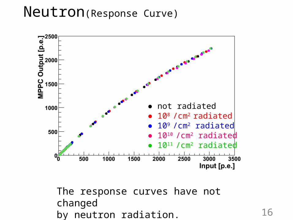
The response curves have not changed by neutron radiation.
● not radiated ● 108 /cm2 radiated ● 109 /cm2 radiated ● 1010 /cm2 radiated ● 1011 /cm2 radiated
Neutron(Response Curve)
16
SummaryMPPC Radiation Resistivity Study(Gamma-ray & Neutron radiation)・ The leakage current and the noise rate are significantly increased.・ There seem no significant changes on the gain and the crosstalk probability.・ The response curves have not changed by radiation.
Even though the dark noise increased by radiation, the MPPC still working as photon-counting device.
Plan・ The estimation of dose at ScECAL (Need simulation tools!).・ More radiation tests with estimated dose. 17
Back Up
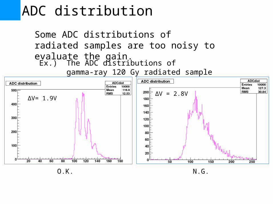
ADC distribution
Some ADC distributions of radiated samples are too noisy to evaluate the gain.
O.K. N.G.
Ex.) The ADC distributions of gamma-ray 120 Gy radiated sample
ΔV= 1.9VΔV = 2.8V
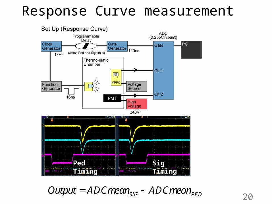
Response Curve measurement
20SIG PEDOutput ADCmean ADCmean
Ped Timing Sig Timing

1 photo-electron
2 photo-electron
NoiseRate measurement(Crosstalk Probability measurement)
21
An example of Threshold curve
( 0.5 . . .)[ ]
[ ]
Scaler count p e ThrNoiseRate Hz
time s
Sca
ler
coun
t
( 1.5 . . .)
( 0.5 . . .)
Scaler count p e ThrCrosstalk Probability
Scaler count p e Thr
0.5 p.e.
1.5 p.e.