mpvc & u pvc catalogue - sizabantu piping...
TRANSCRIPT
M-PVC & U-PVC - 1
M-PVC & U-PVC
CATALOGUE WWW.SIZABANTUPIPINGSYSTEMS.COM
M-PVC & U-PVC - 2
Table of Contents ▌PVC Pressure Pipe 3
Applications 3
Features and Benefits 3
SABS Specification 3
Dimensions of uPVC Pressure Pipe 4
Dimensions of mPVC Pressure Pipe 4
Joining 6
▌Fittings for Pressure Pipe 7
PVC Fittings 7
SG Iron Fittings 9
Resilient Seal Gate Valves 15
▌Physical Properties 16
General 16
The Stress Regression Line 17
Design Stress and Safety Factor (service factor) 18
Effect of Temperature Change 18
The Effect of Ultra Violet Light 19
Chemical Resistance 19
▌Design Considerations 20
Pressure Considerations. 20
Temperature Considerations 23
Ultraviolet Light Considerations 23
Trench Load Considerations 24
Bending 29
Thrust Support 29
Flow Considerations 30
Table of Contents
WWW.SIZABANTUPIPINGSYSTEMS.COM
M-PVC & U-PVC - 3
PVC (Polyvinyl Chloride)
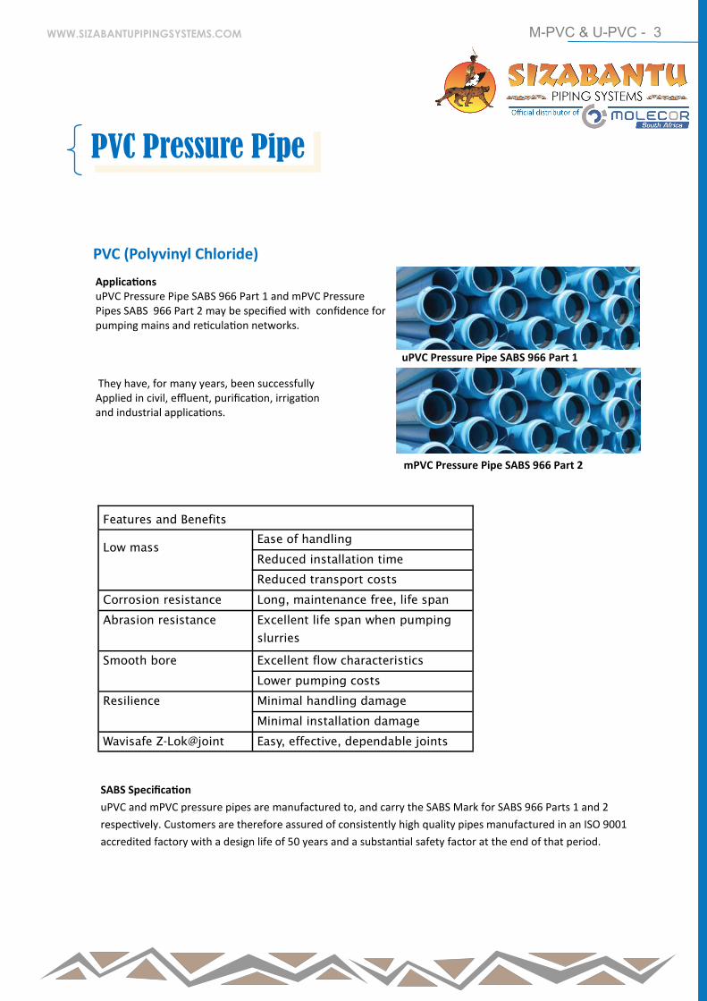
Applications uPVC Pressure Pipe SABS 966 Part 1 and mPVC Pressure Pipes SABS 966 Part 2 may be specified with confidence for pumping mains and reticulation networks. They have, for many years, been successfully Applied in civil, effluent, purification, irrigation and industrial applications.
uPVC Pressure Pipe SABS 966 Part 1
mPVC Pressure Pipe SABS 966 Part 2
Features and Benefits
Low mass
Ease of handling
Reduced installation time
Reduced transport costs
Corrosion resistance Long, maintenance free, life span
Abrasion resistance Excellent life span when pumping
slurries
Smooth bore Excellent flow characteristics
Lower pumping costs
Resilience Minimal handling damage
Minimal installation damage
Wavisafe Z-Lok@joint Easy, effective, dependable joints
SABS Specification
uPVC and mPVC pressure pipes are manufactured to, and carry the SABS Mark for SABS 966 Parts 1 and 2
respectively. Customers are therefore assured of consistently high quality pipes manufactured in an ISO 9001
accredited factory with a design life of 50 years and a substantial safety factor at the end of that period.
PVC Pressure Pipe
WWW.SIZABANTUPIPINGSYSTEMS.COM
M-PVC & U-PVC - 4
Dimensions of uPVC Pressure Pipe
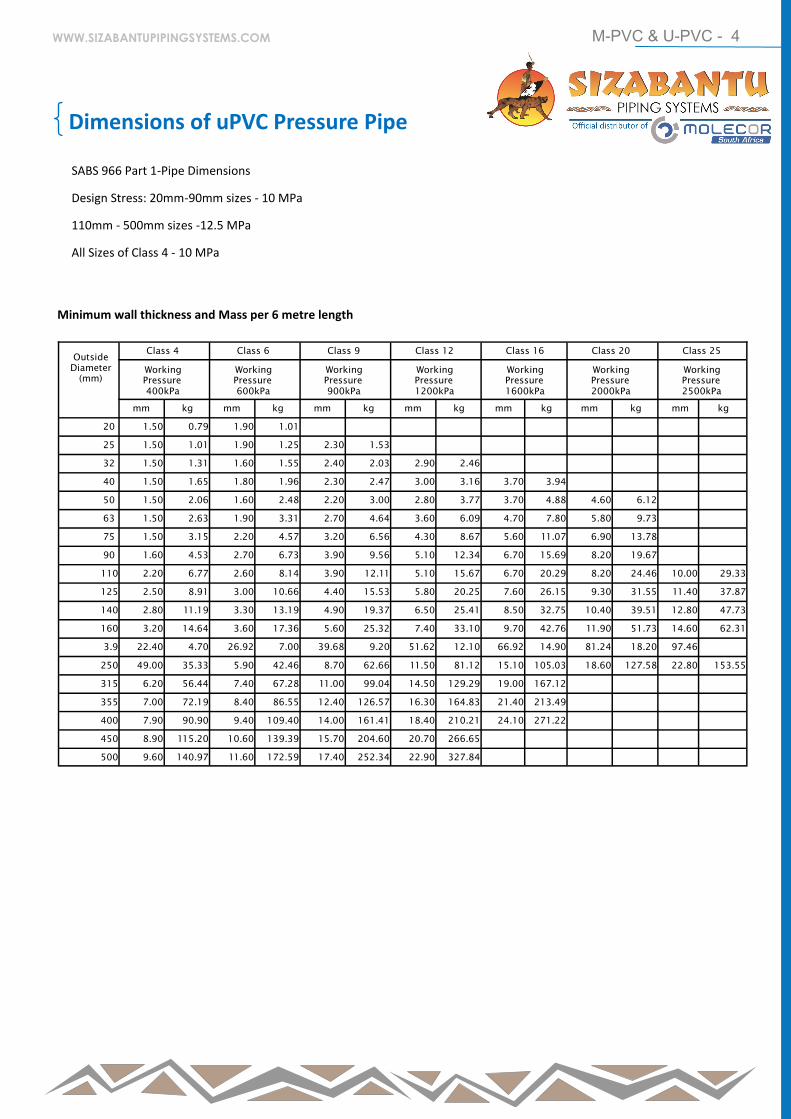
SABS 966 Part 1-Pipe Dimensions
Design Stress: 20mm-90mm sizes - 10 MPa
110mm - 500mm sizes -12.5 MPa
All Sizes of Class 4 - 10 MPa
Outside
Diameter
(mm)
Class 4 Class 6 Class 9 Class 12 Class 16 Class 20 Class 25
Working
Pressure
400kPa
Working
Pressure
600kPa
Working
Pressure
900kPa
Working
Pressure
1200kPa
Working
Pressure
1600kPa
Working
Pressure
2000kPa
Working
Pressure
2500kPa
mm kg mm kg mm kg mm kg mm kg mm kg mm kg
20 1.50 0.79 1.90 1.01
25 1.50 1.01 1.90 1.25 2.30 1.53
32 1.50 1.31 1.60 1.55 2.40 2.03 2.90 2.46
40 1.50 1.65 1.80 1.96 2.30 2.47 3.00 3.16 3.70 3.94
50 1.50 2.06 1.60 2.48 2.20 3.00 2.80 3.77 3.70 4.88 4.60 6.12
63 1.50 2.63 1.90 3.31 2.70 4.64 3.60 6.09 4.70 7.80 5.80 9.73
75 1.50 3.15 2.20 4.57 3.20 6.56 4.30 8.67 5.60 11.07 6.90 13.78
90 1.60 4.53 2.70 6.73 3.90 9.56 5.10 12.34 6.70 15.69 8.20 19.67
110 2.20 6.77 2.60 8.14 3.90 12.11 5.10 15.67 6.70 20.29 8.20 24.46 10.00 29.33
125 2.50 8.91 3.00 10.66 4.40 15.53 5.80 20.25 7.60 26.15 9.30 31.55 11.40 37.87
140 2.80 11.19 3.30 13.19 4.90 19.37 6.50 25.41 8.50 32.75 10.40 39.51 12.80 47.73
160 3.20 14.64 3.60 17.36 5.60 25.32 7.40 33.10 9.70 42.76 11.90 51.73 14.60 62.31
3.9 22.40 4.70 26.92 7.00 39.68 9.20 51.62 12.10 66.92 14.90 81.24 18.20 97.46
250 49.00 35.33 5.90 42.46 8.70 62.66 11.50 81.12 15.10 105.03 18.60 127.58 22.80 153.55
315 6.20 56.44 7.40 67.28 11.00 99.04 14.50 129.29 19.00 167.12
355 7.00 72.19 8.40 86.55 12.40 126.57 16.30 164.83 21.40 213.49
400 7.90 90.90 9.40 109.40 14.00 161.41 18.40 210.21 24.10 271.22
450 8.90 115.20 10.60 139.39 15.70 204.60 20.70 266.65
500 9.60 140.97 11.60 172.59 17.40 252.34 22.90 327.84
Minimum wall thickness and Mass per 6 metre length
WWW.SIZABANTUPIPINGSYSTEMS.COM
M-PVC & U-PVC - 5
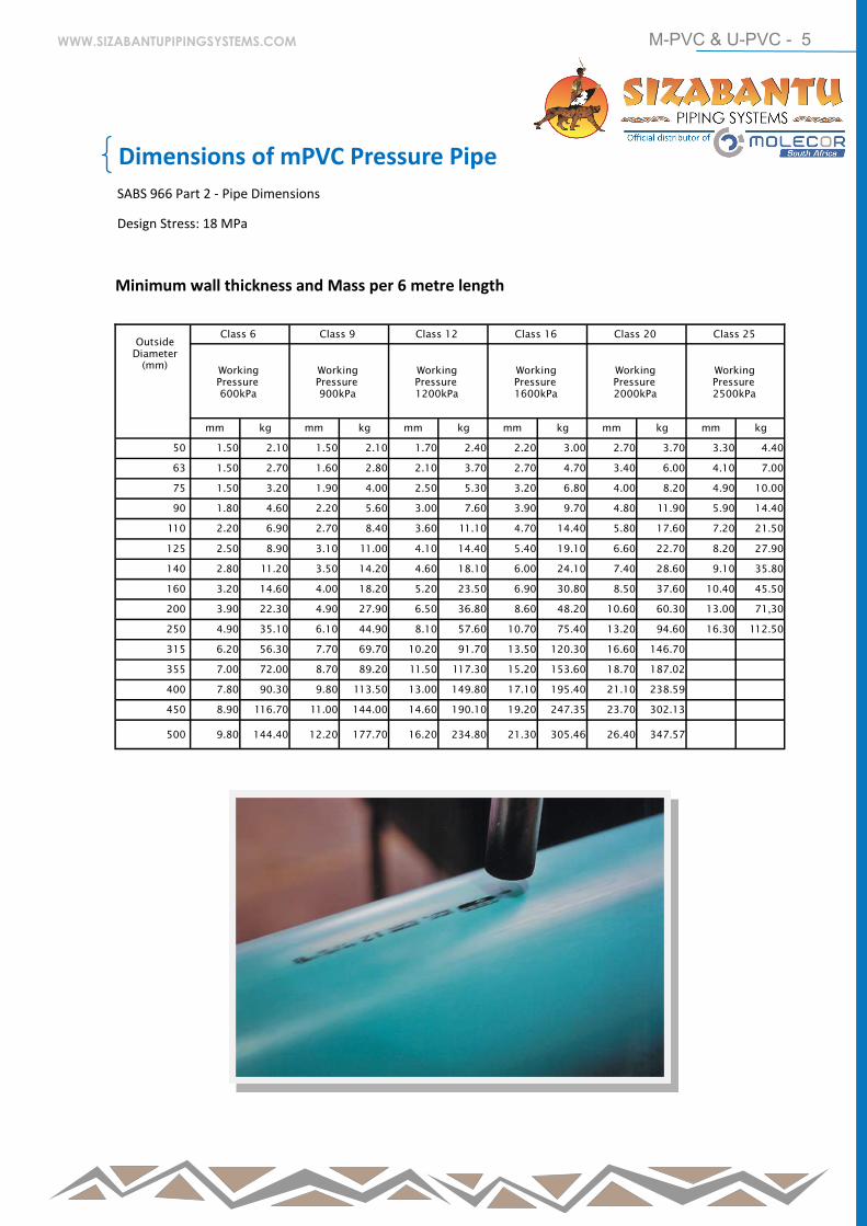
Dimensions of mPVC Pressure Pipe
SABS 966 Part 2 - Pipe Dimensions
Design Stress: 18 MPa
Minimum wall thickness and Mass per 6 metre length
Outside
Diameter
(mm)
Class 6 Class 9 Class 12 Class 16 Class 20 Class 25
Working
Pressure
600kPa
Working
Pressure
900kPa
Working
Pressure
1200kPa
Working
Pressure
1600kPa
Working
Pressure
2000kPa
Working
Pressure
2500kPa
mm kg mm kg mm kg mm kg mm kg mm kg
50 1.50 2.10 1.50 2.10 1.70 2.40 2.20 3.00 2.70 3.70 3.30 4.40
63 1.50 2.70 1.60 2.80 2.10 3.70 2.70 4.70 3.40 6.00 4.10 7.00
75 1.50 3.20 1.90 4.00 2.50 5.30 3.20 6.80 4.00 8.20 4.90 10.00
90 1.80 4.60 2.20 5.60 3.00 7.60 3.90 9.70 4.80 11.90 5.90 14.40
110 2.20 6.90 2.70 8.40 3.60 11.10 4.70 14.40 5.80 17.60 7.20 21.50
125 2.50 8.90 3.10 11.00 4.10 14.40 5.40 19.10 6.60 22.70 8.20 27.90
140 2.80 11.20 3.50 14.20 4.60 18.10 6.00 24.10 7.40 28.60 9.10 35.80
160 3.20 14.60 4.00 18.20 5.20 23.50 6.90 30.80 8.50 37.60 10.40 45.50
200 3.90 22.30 4.90 27.90 6.50 36.80 8.60 48.20 10.60 60.30 13.00 71,30
250 4.90 35.10 6.10 44.90 8.10 57.60 10.70 75.40 13.20 94.60 16.30 112.50
315 6.20 56.30 7.70 69.70 10.20 91.70 13.50 120.30 16.60 146.70
355 7.00 72.00 8.70 89.20 11.50 117.30 15.20 153.60 18.70 187.02
400 7.80 90.30 9.80 113.50 13.00 149.80 17.10 195.40 21.10 238.59
450 8.90 116.70 11.00 144.00 14.60 190.10 19.20 247.35 23.70 302.13
500
9.80
144.40
12.20
177.70
16.20
234.80
21.30
305.46
26.40
347.57
WWW.SIZABANTUPIPINGSYSTEMS.COM
M-PVC & U-PVC - 6
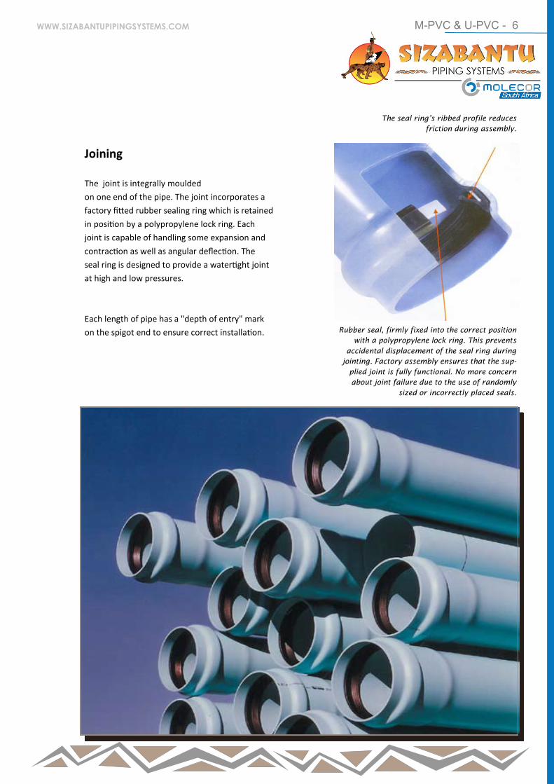
Joining
The joint is integrally moulded
on one end of the pipe. The joint incorporates a
factory fitted rubber sealing ring which is retained
in position by a polypropylene lock ring. Each
joint is capable of handling some expansion and
contraction as well as angular deflection. The
seal ring is designed to provide a watertight joint
at high and low pressures.
Each length of pipe has a "depth of entry" mark
on the spigot end to ensure correct installation.
The seal ring’s ribbed profile reduces
friction during assembly.
Rubber seal, firmly fixed into the correct position
with a polypropylene lock ring. This prevents
accidental displacement of the seal ring during
jointing. Factory assembly ensures that the sup-
plied joint is fully functional. No more concern
about joint failure due to the use of randomly
sized or incorrectly placed seals.
WWW.SIZABANTUPIPINGSYSTEMS.COM
M-PVC & U-PVC - 7
Outside
Diameter
A (mm)
Overall
Length B
(mm)
Radius C
(mm)
Mass (kg)
50 820 175 0.75
63 900 220 1.32
75 970 260 2.02
90 1085 315 3.22
110 1200 385 5.40
125 1330 440 7.65
140 1435 490 10.33
160 1610 560 15.08
200 1920 700 27.82
250 2220 875 50.23
Outside
Diameter
A (mm)
Overall
Length B
(mm)
Radius C (mm)
Mass (kg)
50 820 175 0.75
63 900 220 1.32
15 970 260 2.02
90 1085 315 3.22
110 1200 385 5.40
125 1330 440 7.65
140 1435 490 10.33
160 1610 560 15.08
200 1920 700 27.82
250 2220 875 50.23
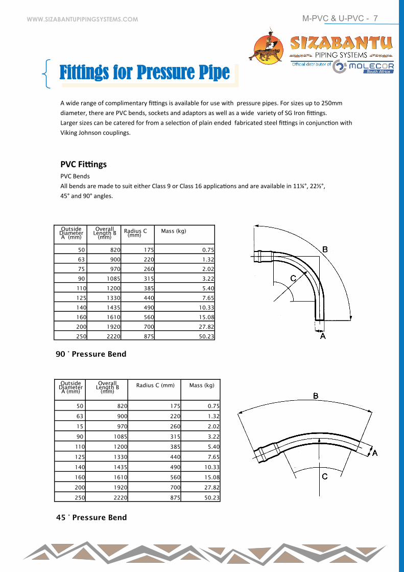
90 ° Pressure Bend
45 ° Pressure Bend
A wide range of complimentary fittings is available for use with pressure pipes. For sizes up to 250mm
diameter, there are PVC bends, sockets and adaptors as well as a wide variety of SG Iron fittings.
Larger sizes can be catered for from a selection of plain ended fabricated steel fittings in conjunction with
Viking Johnson couplings.
PVC Fittings PVC Bends
All bends are made to suit either Class 9 or Class 16 applications and are available in 11¼°, 22½°,
45° and 90° angles.
Fittings for Pressure Pipe
WWW.SIZABANTUPIPINGSYSTEMS.COM
M-PVC & U-PVC - 8
Outside
Diameter A
(mm)
Overall
Length B
(mm)
Radius C
(mm)
Mass (kg)
50 640 175 0.59
63 670 220 0.98
75 700 260 1.45
90 755 315 2.25
110 800 385 3.60
125 670 440 5.00
140 920 490 6.62
160 1025 560 9.60
200 1190 700 17.24
250 1305 875 29.53
22½°Pressure Bend
Outside
Diameter A
(mm)
Overall
Length B
(mm)
Radius C
(mm)
Mass (kg)
50 640 175 0.59
63 670 220 0.98
75 700 260 1.45
90 755 315 2.25
110 800 385 3.60
125 670 440 5.00
140 920 490 6.62
160 1025 560 9.60
200 1190 700 17.24
250 1305 875 29.53
11¼° Pressure Bend
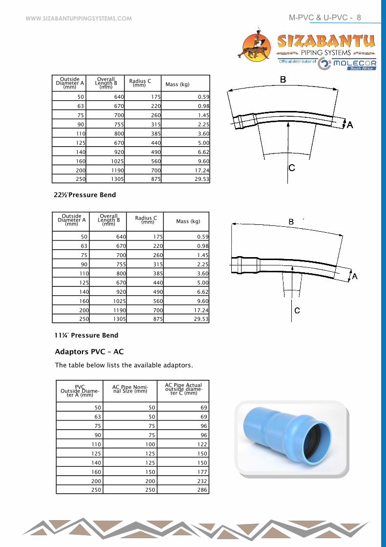
Adaptors PVC – AC
The table below lists the available adaptors.
PVC
Outside Diame-
ter A (mm)
AC Pipe Nomi-
nal Size (mm)
AC Pipe Actual
outside diame-
ter C (mm)
50 50 69
63 50 69
75 75 96
90 75 96
110 100 122
125 125 150
140 125 150
160 150 177
200 200 232
250 250 286
WWW.SIZABANTUPIPINGSYSTEMS.COM
M-PVC & U-PVC - 9
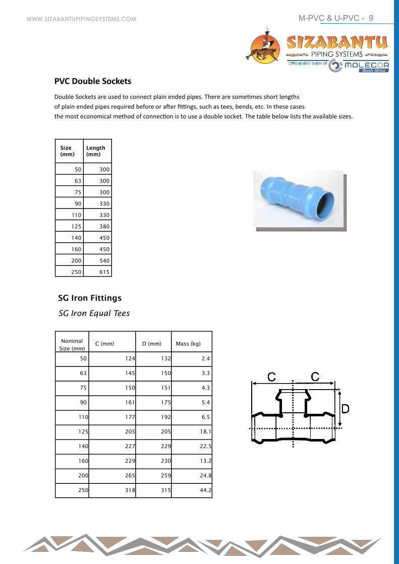
PVC Double Sockets
Double Sockets are used to connect plain ended pipes. There are sometimes short lengths
of plain ended pipes required before or after fittings, such as tees, bends, etc. In these cases
the most economical method of connection is to use a double socket. The table below lists the available sizes.
Size
(mm)
Length
(mm)
50 300
63 300
75 300
90 330
110 330
125 380
140 450
160 450
200 540
250 615
Nominal
Size (mm)
C (mm)
D (mm)
Mass (kg)
50 124 132 2.4
63 145 150 3.3
75 150 151 4.3
90 161 175 5.4
110 177 192 6.5
125 205 205 18.1
140 227 229 22.5
160 229 230 13.2
200 265 259 24.8
250 318 315 44.2
SG Iron Fittings
SG Iron Equal Tees
WWW.SIZABANTUPIPINGSYSTEMS.COM
M-PVC & U-PVC - 10
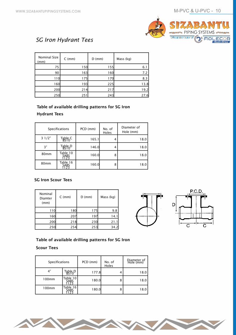
SG Iron Scour Tees
SG Iron Hydrant Tees
Nominal Size
(mm)
C (mm)
D (mm)
Mass (kg)
75 150 155 6.1
90 163 160 7.2
110 175 170 8.3
160 193 225 13.8
200 214 217 19.2
250 251 243 27.6
Table of available drilling patterns for SG Iron
Hydrant Tees
Specifications
PCD (mm)
No. of
Holes
Diameter of
Hole (mm)
3 1/2”
Table C BS10
165.1
4
18.0
3”
Table D BS10
146.0
4
18.0
80mm Table 10
SABS
1123
160.0
8
18.0
80mm Table 16
SABS
1123
160.0
8
18.0
Nominal
Diamter
(mm)
C (mm)
D (mm)
Mass (kg)
110 180 175 9.8
160 207 197 14.1
200 218 230 21.1
250 254 253 34.2
Table of available drilling patterns for SG Iron
Scour Tees
Specifications
PCD (mm)
No. of
Holes
Diameter of
Hole (mm)
4”
Table D BS10
177.8
4
18.0
100mm Table 10
SABS
1123
180.0
8
18.0
100mm Table 16
SABS
1123
180.0
8
18.0
WWW.SIZABANTUPIPINGSYSTEMS.COM
M-PVC & U-PVC - 11
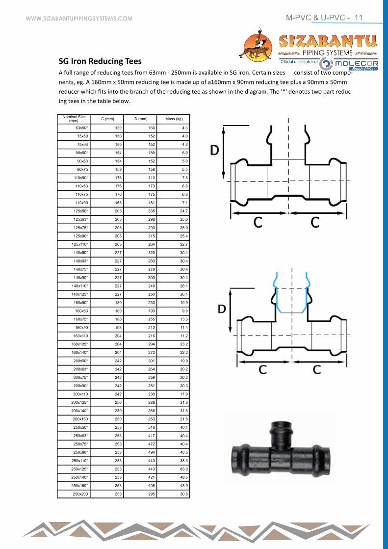
SG Iron Reducing Tees A full range of reducing tees from 63mm - 250mm is available in SG iron. Certain sizes consist of two compo-
nents, eg. A 160mm x 50mm reducing tee is made up of a160mm x 90mm reducing tee plus a 90mm x 50mm
reducer which fits into the branch of the reducing tee as shown in the diagram. The '*' denotes two part reduc-
ing tees in the table below.
Nominal Size (mm) C (mm) D (mm) Mass (kg)
63x50* 130 160 4.3
75x50 150 152 4.0
75x63 150 152 4.3
90x50* 154 189 6.0
90x63 154 152 5.0
90x75 159 158 5.5
110x50* 176 210 7.8
110x63 176 173 6.8
110x75 176 175 6.6
110x90 166 181 7.1
125x50* 205 335 24.7
125x63* 205 298 25.0
125x75* 205 293 25.0
125x90* 205 315 25.4
125x110* 205 264 22.7
140x50* 227 320 30.1
140x63* 227 283 30.4
140x75* 227 278 30.4
140x90* 227 300 30.4
140x110* 227 249 28.1
140x125* 227 250 26.1
160x50* 180 230 10.9
160x63 180 193 9.9
160x75* 180 255 13.3
160x90 193 212 11.4
160x110 204 216 11.2
160x125* 204 294 23.2
160x140* 204 272 22.2
200x50* 242 301 19.9
200x63* 242 264 20.2
200x75* 242 259 20.2
200x90* 242 281 20.3
200x110 242 230 17.9
200x125* 250 288 31.8
200x140* 250 266 31.8
200x160 250 253 21.6
250x50* 253 516 40.1
250x63* 253 417 40.4
250x75* 253 472 40.4
250x90* 253 494 40.5
250x110* 253 443 38.3
250x125* 253 443 83.0
250x140* 253 421 48.5
250x160* 253 408 43.0
250x200 253 295 30.8
WWW.SIZABANTUPIPINGSYSTEMS.COM
M-PVC & U-PVC - 12
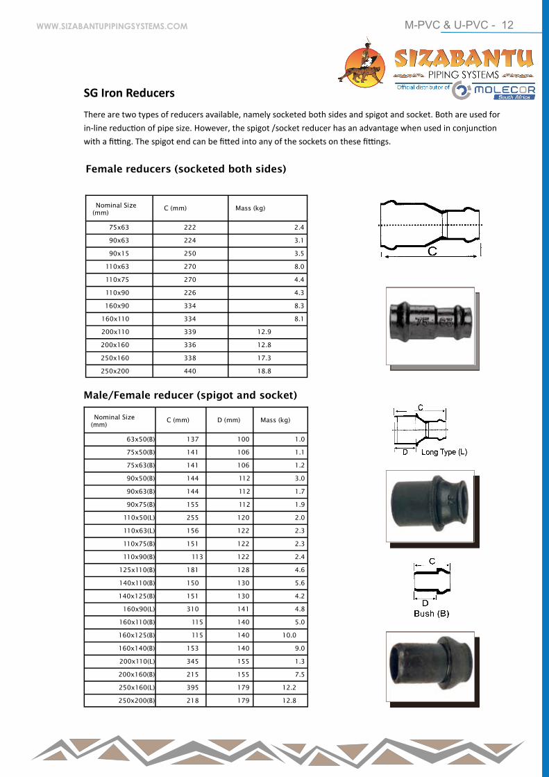
SG Iron Reducers
There are two types of reducers available, namely socketed both sides and spigot and socket. Both are used for
in-line reduction of pipe size. However, the spigot /socket reducer has an advantage when used in conjunction
with a fitting. The spigot end can be fitted into any of the sockets on these fittings.
Female reducers (socketed both sides)
Nominal Size
(mm)
C (mm)
Mass (kg)
75x63 222 2.4
90x63 224 3.1
90x15 250 3.5
110x63 270 8.0
110x75 270 4.4
110x90 226 4.3
160x90 334 8.3
160x110 334 8.1
200x110 339 12.9
200x160 336 12.8
250x160 338 17.3
250x200 440 18.8
Male/Female reducer (spigot and socket)
Nominal Size
(mm)
C (mm)
D (mm)
Mass (kg)
63x50(B) 137 100 1.0
75x50(B) 141 106 1.1
75x63(B) 141 106 1.2
90x50(B) 144 112 3.0
90x63(B) 144 112 1.7
90x75(B) 155 112 1.9
110x50(L) 255 120 2.0
110x63(L) 156 122 2.3
110x75(B) 151 122 2.3
110x90(B) 113 122 2.4
125x110(B) 181 128 4.6
140x110(B) 150 130 5.6
140x125(B) 151 130 4.2
160x90(L) 310 141 4.8
160x110(B) 115 140 5.0
160x125(B) 115 140 10.0
160x140(B) 153 140 9.0
200x110(L) 345 155 1.3
200x160(B) 215 155 7.5
250x160(L) 395 179 12.2
250x200(B) 218 179 12.8
WWW.SIZABANTUPIPINGSYSTEMS.COM
M-PVC & U-PVC - 13
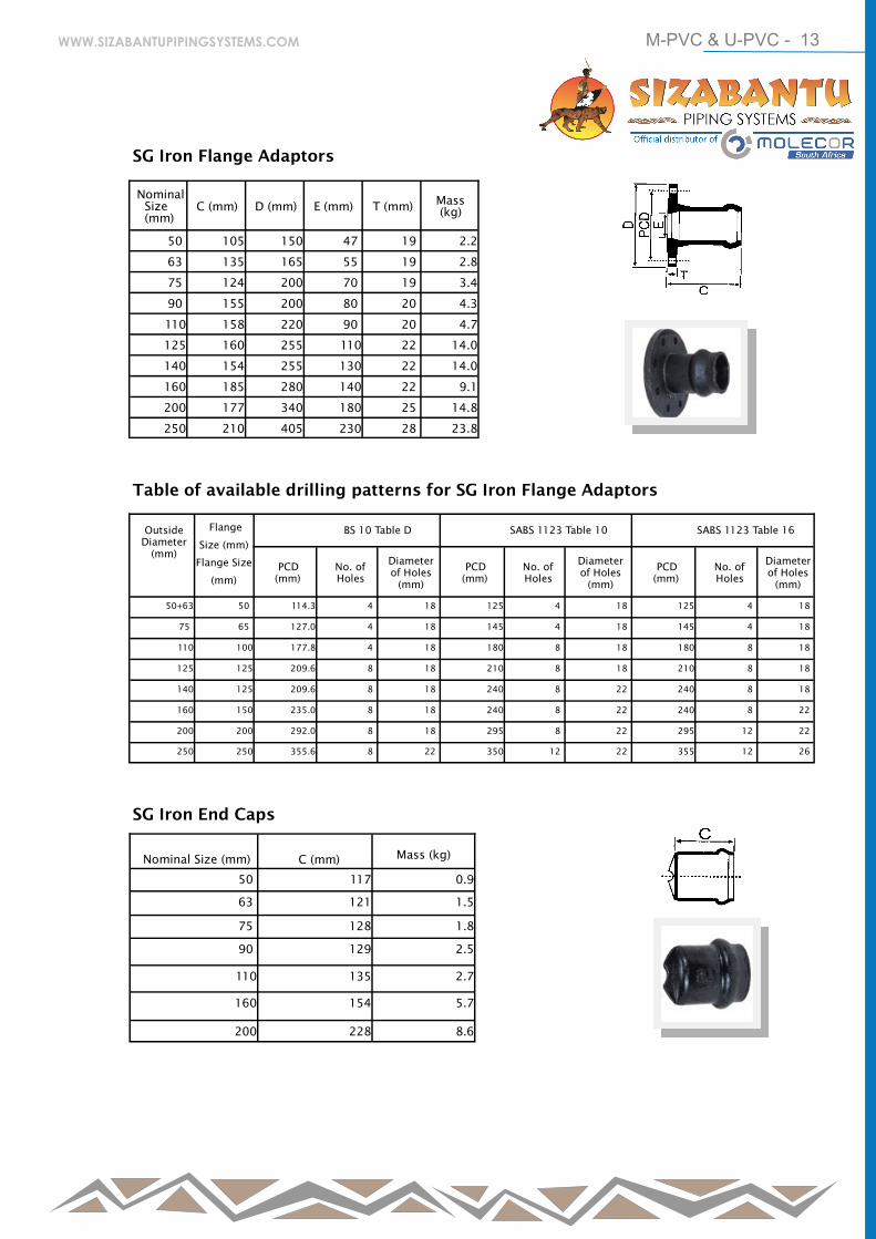
SG Iron Flange Adaptors
Nominal
Size
(mm)
C (mm)
D (mm)
E (mm)
T (mm)
Mass
(kg)
50 105 150 47 19 2.2
63 135 165 55 19 2.8
75 124 200 70 19 3.4
90 155 200 80 20 4.3
110 158 220 90 20 4.7
125 160 255 110 22 14.0
140 154 255 130 22 14.0
160 185 280 140 22 9.1
200 177 340 180 25 14.8
250 210 405 230 28 23.8
Table of available drilling patterns for SG Iron Flange Adaptors
Outside
Diameter
(mm)
Flange
Size (mm)
Flange Size
(mm)
BS 10 Table D
SABS 1123 Table 10
SABS 1123 Table 16
PCD
(mm)
No. of
Holes
Diameter
of Holes
(mm)
PCD
(mm)
No. of
Holes
Diameter
of Holes
(mm)
PCD
(mm)
No. of
Holes
Diameter
of Holes
(mm)
50+63 50 114.3 4 18 125 4 18 125 4 18
75 65 127.0 4 18 145 4 18 145 4 18
110 100 177.8 4 18 180 8 18 180 8 18
125 125 209.6 8 18 210 8 18 210 8 18
140 125 209.6 8 18 240 8 22 240 8 18
160 150 235.0 8 18 240 8 22 240 8 22
200 200 292.0 8 18 295 8 22 295 12 22
250 250 355.6 8 22 350 12 22 355 12 26
SG Iron End Caps
Nominal Size (mm)
C (mm)
Mass (kg)
50 117 0.9
63 121 1.5
75 128 1.8
90 129 2.5
110 135 2.7
160 154 5.7
200 228 8.6
WWW.SIZABANTUPIPINGSYSTEMS.COM
M-PVC & U-PVC - 14
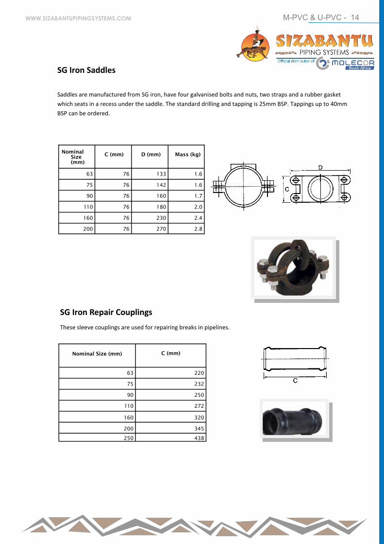
SG Iron Saddles
Saddles are manufactured from SG iron, have four galvanised bolts and nuts, two straps and a rubber gasket
which seats in a recess under the saddle. The standard drilling and tapping is 25mm BSP. Tappings up to 40mm
BSP can be ordered.
Nominal
Size
(mm)
C (mm)
D (mm)
Mass (kg)
63 76 133 1.6
75 76 142 1.6
90 76 160 1.7
110 76 180 2.0
160 76 230 2.4
200 76 270 2.8
SG Iron Repair Couplings
These sleeve couplings are used for repairing breaks in pipelines.
Nominal Size (mm)
C (mm)
63 220
75 232
90 250
110 272
160 320
200 345
250 438
WWW.SIZABANTUPIPINGSYSTEMS.COM
M-PVC & U-PVC - 15
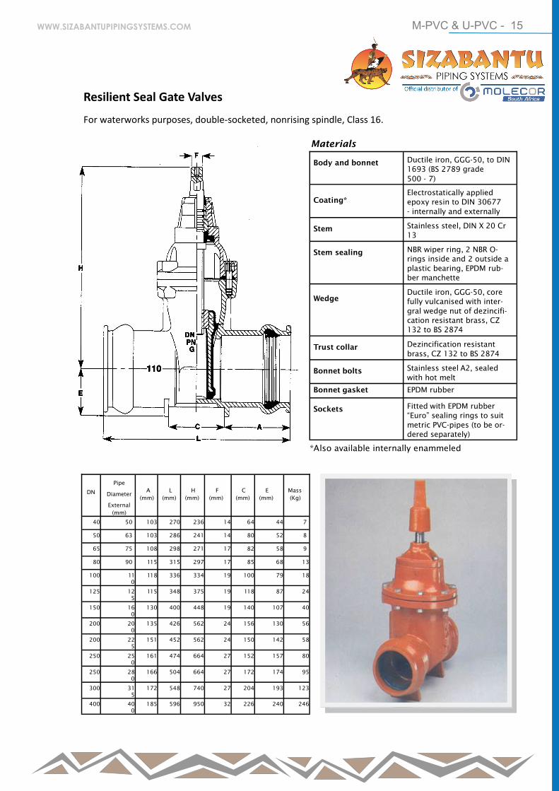
Resilient Seal Gate Valves
For waterworks purposes, double-socketed, nonrising spindle, Class 16.
Body and bonnet Ductile iron, GGG-50, to DIN
1693 (BS 2789 grade
500 - 7)
Coating*
Electrostatically applied
epoxy resin to DIN 30677
- internally and externally
Stem Stainless steel, DIN X 20 Cr
13
Stem sealing NBR wiper ring, 2 NBR O-
rings inside and 2 outside a
plastic bearing, EPDM rub-
ber manchette
Wedge
Ductile iron, GGG-50, core
fully vulcanised with inter-
gral wedge nut of dezincifi-
cation resistant brass, CZ
132 to BS 2874
Trust collar Dezincification resistant
brass, CZ 132 to BS 2874
Bonnet bolts Stainless steel A2, sealed
with hot melt
Bonnet gasket EPDM rubber
Sockets Fitted with EPDM rubber
“Euro” sealing rings to suit
metric PVC-pipes (to be or-
dered separately)
Materials
DN
Pipe
Diameter
External
(mm)
A
(mm)
L
(mm)
H
(mm)
F
(mm)
C
(mm)
E
(mm)
Mass
(Kg)
40 50 103 270 236 14 64 44 7
50 63 103 286 241 14 80 52 8
65 75 108 298 271 17 82 58 9
80 90 115 315 297 17 85 68 13
100 11
0
118 336 334 19 100 79 18
125 12
5
115 348 375 19 118 87 24
150 16
0
130 400 448 19 140 107 40
200 20
0
135 426 562 24 156 130 56
200 22
5
151 452 562 24 150 142 58
250 25
0
161 474 664 27 152 157 80
250 28
0
166 504 664 27 172 174 95
300 31
5
172 548 740 27 204 193 123
400 40
0
185 596 950 32 226 240 246
*Also available internally enammeled
WWW.SIZABANTUPIPINGSYSTEMS.COM
M-PVC & U-PVC - 16
Polyvinyl Chloride (PVC) is a thermoplastic
material which consists of a PVC resin
compounded with varying proportions of
stabilizers, lubricants, fillers, pigments,
plasticizers and processing aids. Different
formulations of these ingredients are used
to obtain specific properties for different
applications. Pipes can therefore be
developed to meet the requirements of a
wide variety of applications and conditions.
General
The general properties given in the table below are those for PVC compound formulations used in pipe
manufacture. It should be noted that these properties are relative to temperature and the duration of stress
application.
Physical
Units
Value
Coefficient of linear expansion K-1 6 × 10⁻⁵
Density kg/m2 1.4 × 10³
Flammability (oxygenindex) % 45
Shore hardness 80
Softening point (Vicat - minimum) °C 76
Specific heat J/kg/K 1.0 × 10³
Thermal conductivity (at 0° - 50°C) W/m/K 0.14
Mechanical
Elastic Modulus (longterm - 50 years) MPa 2800
Elastic Modulus (short term - 100 seconds) MPa 1400
Elongation at break % 75
Poisson’s Ratio 0.4
Tensile strength (50 year - extrapolated) MPa 26
Tensile strength (minimum) MPa 48
Friction Factors
Manning 0.008 - 0.009
Hazen Williams 150
Nikuradse roughness (k) mm 0.003 - 0.015
Physical Properties
WWW.SIZABANTUPIPINGSYSTEMS.COM
M-PVC & U-PVC - 17
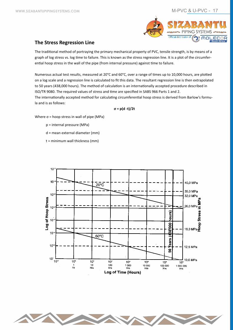
The Stress Regression Line
The traditional method of portraying the primary mechanical property of PVC, tensile strength, is by means of a
graph of log stress vs. log time to failure. This is known as the stress regression line. It is a plot of the circumfer-
ential hoop stress in the wall of the pipe (from internal pressure) against time to failure.
Numerous actual test results, measured at 20°C and 60°C, over a range of times up to 10,000 hours, are plotted
on a log scale and a regression line is calculated to fit this data. The resultant regression line is then extrapolated
to 50 years (438,000 hours). The method of calculation is an internationally accepted procedure described in
ISO/TR 9080. The required values of stress and time are specified in SABS 966 Parts 1 and 2.
The internationally accepted method for calculating circumferential hoop stress is derived from Barlow's formu-
la and is as follows:
σ = p(d -t)/2t
Where σ = hoop stress in wall of pipe (MPa)
p = internal pressure (MPa)
d = mean external diameter (mm)
t = minimum wall thickness (mm)
WWW.SIZABANTUPIPINGSYSTEMS.COM

M-PVC & U-PVC - 18
Design Stress and Safety Factor
(service factor)
Safety factors take into account handling conditions,
service conditions and other circumstances not directly
considered in the design.
In terms of SABS 966 the following safety factors have
been adopted. These factors have resulted in the given
design stresses being applicable. The design stress is
derived by dividing the 50 year hoop stress (26 MPa -
from the stress regression line ) by the chosen safety
factor.
Applying Barlow's formula (below) it is now possible to
calculate the minimum wall thickness for any given size
and pressure class of pipe.
t = p × d / (2σ + p)
Where: t = minimum wall thickness (mm)
p = pressure (MPa)
d = mean external diameter (mm)
σ = design stress (MPa)
For example the minimum wall thickness for a 250 mm
Class 16 uPVC pipe is:
t = 1.6 x 250 /{(2x 12.5)+ 1.6} =15.04 mm
(rounded up to 15.1 mm for manufacture)
Effect of Temperature Change
Working Pressure
The standard design temperature for PVC pipes is 20°C
and working pressures are usually quoted for this tem-
perature. PVC pressure pipes function perfectly well be-
low 20°C, right down to freezing point, and can in fact
withstand higher pressures than those quoted at 20°C.
As can be seen from the stress regression lines, the
creep rupture strength diminishes with increasing tem-
perature and working pressures must be down-rated if
the same factors of safety are to be maintained. The
applicable reduction factors are given under
"Temperature Considerations" later.
Expansion and Contraction
All plastics have high coefficients of expansion and con-
traction, several times that of metals. This must be al-
lowed for in any installation by the use of expansion
joints, expansion loops etc.
Sub Zero Temperatures
Water has been known to freeze in PVC pipes without
causing fractures, but permanent strain can result, lead-
ing to severe reduction in the working life of the pipe.
Hence PVC pipes - like other pipes - should be protected
against sub zero temperatures.
uPVC mPVC
Sizes ≤
90 mm
Sizes ≥
110 mm
All
Sizes
Safety Factor
2.5
2.0
1.4
Design Stress (Mpa)
10.0
12.5
18.0
Material
Co-efficient of expansion (K-1)
PVC 8 × 10⁻⁵
HDPE 20 × 10-5
Steel 1.2 × 10⁻⁵
Copper 2.0 × 10⁻⁵
WWW.SIZABANTUPIPINGSYSTEMS.COM
M-PVC & U-PVC - 19
The Effect of Ultra Violet Light
Most plastics are affected by UV light. PVC pressure pipes have UV light stabilisers incorporated in their
formulation but if pressure pipes have to be exposed for an indefinite period, they should be painted, preferably
with one coat of white Alkyd Enamel or PVA.
Long-term exposure (more than 4 to 6 months - dependant on climatic conditions) to UV light can cause
discolouration of the pigments in the pipe and, in severe cases, lead to some embrittlement. Such embrittlement
affects the ability to withstand impacts but does not reduce pressure handling capabilities.
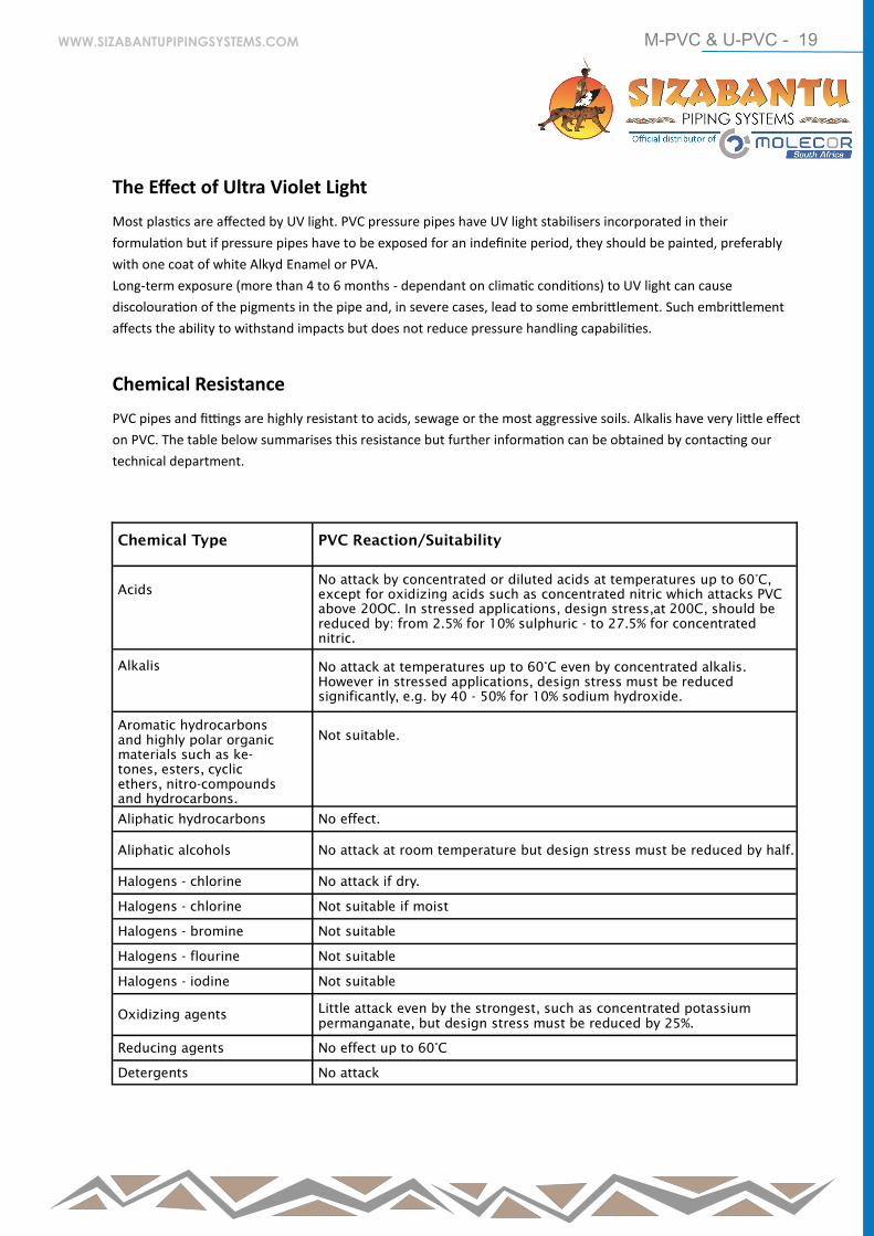
Chemical Resistance
PVC pipes and fittings are highly resistant to acids, sewage or the most aggressive soils. Alkalis have very little effect
on PVC. The table below summarises this resistance but further information can be obtained by contacting our
technical department.
Chemical Type
PVC Reaction/Suitability
Acids
No attack by concentrated or diluted acids at temperatures up to 60°C,
except for oxidizing acids such as concentrated nitric which attacks PVC
above 20OC. In stressed applications, design stress,at 200C, should be
reduced by: from 2.5% for 10% sulphuric - to 27.5% for concentrated
nitric.
Alkalis
No attack at temperatures up to 60°C even by concentrated alkalis.
However in stressed applications, design stress must be reduced
significantly, e.g. by 40 - 50% for 10% sodium hydroxide.
Aromatic hydrocarbons
and highly polar organic
materials such as ke-
tones, esters, cyclic
ethers, nitro-compounds
and hydrocarbons.
Not suitable.
Aliphatic hydrocarbons No effect.
Aliphatic alcohols
No attack at room temperature but design stress must be reduced by half.
Halogens - chlorine No attack if dry.
Halogens - chlorine Not suitable if moist
Halogens - bromine Not suitable
Halogens - flourine Not suitable
Halogens - iodine Not suitable
Oxidizing agents Little attack even by the strongest, such as concentrated potassium
permanganate, but design stress must be reduced by 25%.
Reducing agents No effect up to 60°C
Detergents No attack
WWW.SIZABANTUPIPINGSYSTEMS.COM
M-PVC & U-PVC - 20
In SABS 966 there are 7 different pressure classes. These classes inlude suitable safety factors and are intended as a
guide to trouble free operation under average service conditions. There are however many factors which must be
considered when determining the severity of service and the appropriate class of pipe. This section is provided as a
guide to the designer in the light of his or her knowledge of the particular circumstances.
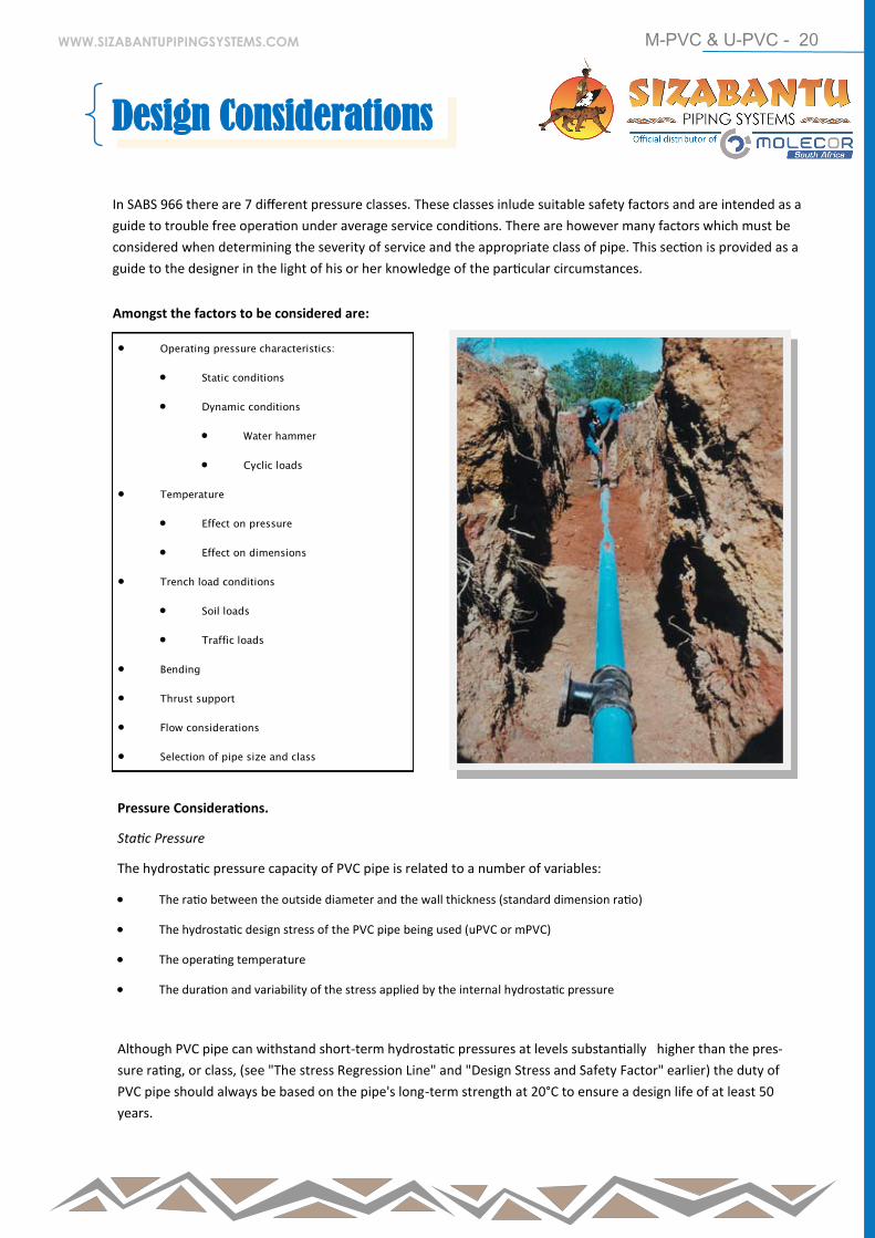
Amongst the factors to be considered are:
Operating pressure characteristics:
Static conditions
Dynamic conditions
Water hammer
Cyclic loads
Temperature
Effect on pressure
Effect on dimensions
Trench load conditions
Soil loads
Traffic loads
Bending
Thrust support
Flow considerations
Selection of pipe size and class
Pressure Considerations.
Static Pressure
The hydrostatic pressure capacity of PVC pipe is related to a number of variables:
The ratio between the outside diameter and the wall thickness (standard dimension ratio)
The hydrostatic design stress of the PVC pipe being used (uPVC or mPVC)
The operating temperature
The duration and variability of the stress applied by the internal hydrostatic pressure
Although PVC pipe can withstand short-term hydrostatic pressures at levels substantially higher than the pres-
sure rating, or class, (see "The stress Regression Line" and "Design Stress and Safety Factor" earlier) the duty of
PVC pipe should always be based on the pipe's long-term strength at 20°C to ensure a design life of at least 50
years.
Design Considerations
WWW.SIZABANTUPIPINGSYSTEMS.COM
M-PVC & U-PVC - 21
As stated earlier, the relationship between the internal
pressure, the diameter and wall thickness and the cir-
cumferential hoop stress in the pipe wall, is given by the
Barlow Formula, which can also be expressed as follows.
p = 2 x t x σ/d
or alternatively
t = p x d/(2σ + p)
Where: p = internal pressure (MPa)
t = minimum wall thickness (mm)
d = mean outside diameter (mm)
q =circumferential hoop stress (MPa)
These formulae have been standardized for use in de-
sign, testing and research and are applicable at all levels
of pressure and stress.
For design purposes, p is taken as the maximum allowa-
ble working pressure and q, the maximum allowable
hoop stress at 20°C.
The design hoop stresses used in SABS 966 are as fol-
lows:
Part 1 sizes up to 90mm 10 MPa
other sizes 12.5 MPa
Part 2 all sizes 18 MPa
Dynamic Pressure
The pressure classes of SABS 966 PVC pipes are based on
constant internal pressures. PVC pipes are however ca-
pable of handling dynamic pressure events which ex-
ceed the values given by the classes but such occurrenc-
es can have a negative effect on the normal 50 year life
expectancy, and in extreme cases can result in product
failure.
PVC pipes are capable of handling accidental events, such as pressure surges due to a power cut. However, if repetitive surges are likely to exceed about 100,000 occurrences during a 50 year operating lifetime, which is equivalent to an average of one surge wave every four hours for the total life of the pipe, then fatigue is a pos-sibility and a fatigue design should be carried out. For most water supply lines this frequency of surges never occurs.
If stress peaks in excess of the design stresses are pre-
sent, fatigue proceeds more rapidly and failure can
occur earlier. For this reason peak pressures should
not be allowed to exceed maximum recommended
working pressures.
Studies of fatigue response have shown that a fatigue
crack initiates from some dislocation in the material
matrix, usually towards the inside surface of the pipe
where stress levels are highest, and propagates or grows
with each stress cycle at a rate dependent on the magni-
tude of the stress. Ultimately the crack will penetrate
the pipe wall, extending from a few millimetres to a
few centimetres long in the axial direction and will pro-
duce a leak.
It is important to appreciate that the growth of a
fatigue crack is primarily dependent on the stress
cycle amplitude, i.e. the maximum pressure minus
the minimum pressure. Therefore a pipe subject-
ed to a pressure cycle of zero to half working pres-
sure is as much in danger of fatigue as one subject-
ed to a pressure cycle of half to full working pres-
sure. Thus pipe fatigue failures occur just as fre-
quently at high points in the system as at low
points where the total pressure is greater.
WWW.SIZABANTUPIPINGSYSTEMS.COM
M-PVC & U-PVC - 22
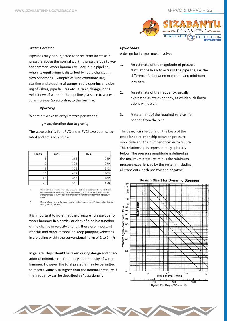
Water Hammer
Pipelines may be subjected to short-term increase in
pressure above the normal working pressure due to wa-
ter hammer. Water hammer will occur in a pipeline
when its equilibrium is disturbed by rapid changes in
flow conditions. Examples of such conditions are;
starting and stopping of pumps, rapid opening and clos-
ing of valves, pipe failures etc. A rapid change in the
velocity Δv of water in the pipeline gives rise to a pres-
sure increase Δp according to the formula:
Δp=cΔv/g
Where:c = wave celerity (metres per second)
g = acceleration due to gravity
The wave celerity for uPVC and mPVC have been calcu-
lated and are given below.
It is important to note that the pressure I crease due to
water hammer in a particular class of pipe is a function
of the change in velocity and it is therefore important
(for this and other reasons) to keep pumping velocities
in a pipeline within the conventional norm of 1 to 2 m/s.
In general steps should be taken during design and oper-
ation to minimize the frequency and intensity of water
hammer. However the total pressure may be permitted
to reach a value 50% higher than the nominal pressure if
the frequency can be described as "occasional".
Cyclic Loads
A design for fatigue must involve:
1. An estimate of the magnitude of pressure
fluctuations likely to occur in the pipe line, i.e. the
difference Δp between maximum and minimum
pressures.
2. An estimate of the frequency, usually
expressed as cycles per day, at which such fluctu
ations will occur.
3. A statement of the required service life
needed from the pipe.
The design can be done on the basis of the
established relationship between pressure
amplitude and the number of cycles to failure.
This relationship is represented graphically
below. The pressure amplitude is defined as
the maximum pressure, minus the minimum
pressure experienced by the system, including
all transients, both positive and negative.
Class m/s. m/s.
6 263 249
9 325 270
12 378 312
16 439 363
20 495 407
25 559 458
1. Since part of the formula for calculating wave celerity incorporates the ratio between
diameter and wall thickness (SDR), which is roughly constant for all sizes within a
pressure class, the wave celerities are also constant for all sizes within a pressure
class.
2. By way of comparison the wave celerity for steel pipes is about 3 times higher than for
PVC (1000 to 1400 m/s).
WWW.SIZABANTUPIPINGSYSTEMS.COM
M-PVC & U-PVC - 23
Example A sewer rising main with a static rise of 15 metres and a total pumping head of 50 metres is designed to service a population of 400 growing to 1,000 in 50 years. Throughput is 300 litres/head/day average and well ca-pacity is 20,000 litres.
Over the life of the scheme the average throughput is 210,000 litres/day. Assuming that half the well capacity is utilised, then the average switching rate will be 21 cycles/day. Assuming there is no significant water ham-mer, the dynamic range is 35 metres. According to the chart a Class. 6 pipe is satisfactory.
Temperature Considerations
Effect on Pressure
The pressure classes of PVC pipes carrying the SABS 966 mark have been allocated on the basis of design at 20°C. Any pipes used in applications where operating temper-atures exceed 25°C need to be de-rated to ensure that the 50 year design life, or the safety factor, is not ad-versely affected. The following pressure reduction fac-tors should be applied.
At lower temperatures, between 20°C and 0°C, the pres-
sure handling capability does increase but it is recom-
mended that this be ignored. If water freezes inside a
PVC pipe permanent strain (if not fracture) may occur,
leading to a possible severe reduction in the working life
of the pipe.
Effect on Dimensions
Due to the relatively high coefficient of
expansion and contraction (given in "Expansion
and contraction" earlier) it is necessary to
make allowance for this in any design and
installation which is exposed to wide variations
of temperature.
PVC pipes will expand or contract by 0.08mm
per metre per C rise or fall in temperature. A
30°C temperature rise will therefore cause a
14.4mm expansion of a 6 metre pipe.
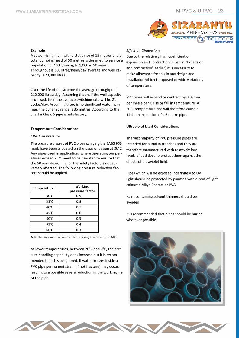
Ultraviolet Light Considerations
The vast majority of PVC pressure pipes are
intended for burial in trenches and they are
therefore manufactured with relatively low
levels of additives to protect them against the
effects of ultraviolet light.
Pipes which will be exposed indefinitely to UV
light should be protected by painting with a coat of light
coloured Alkyd Enamel or PVA.
Paint containing solvent thinners should be
avoided.
It is recommended that pipes should be buried
wherever possible.
Temperature Working
pressure factor
30°C 0.9
35°C 0.8
40°C 0.7
45°C 0.6
50°C 0.5
55°C 0.4
60°C 0.3
N.B. The maximum recommended working temperature is 60˚C
WWW.SIZABANTUPIPINGSYSTEMS.COM
M-PVC & U-PVC - 24
Trench Load Considerations
It has been well established by researchers
over many years that, for flexible pipes, it is the
interaction between the soil and the pipe which
has to be considered more extensively than is
the case for rigid pipes where the material
strength of the pipe is the critical issue. The
points discussed here are given as a guide
only to aid design by the engineer.
Soil and Traffic Loads
The vertical load on a PVC pipe due to soil is
a function of the trench width and depth, the
unit weight and type of the soil and the pipe
diameter and wall thickness. This loading must
generally be corrected because of the fact that
the soil is cohesive and the side fill reacts with
the fill above the pipe. Furthermore flexible
pipes deflect and shed load to the side fill.
This vertical deflection is limited by lateral soil
resistance. The resultant load is therefore less
than that which column theory suggests.
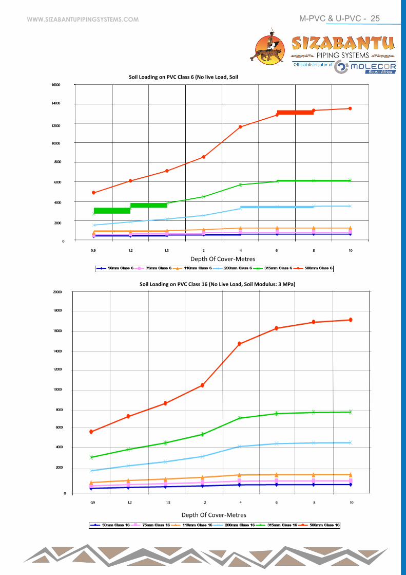
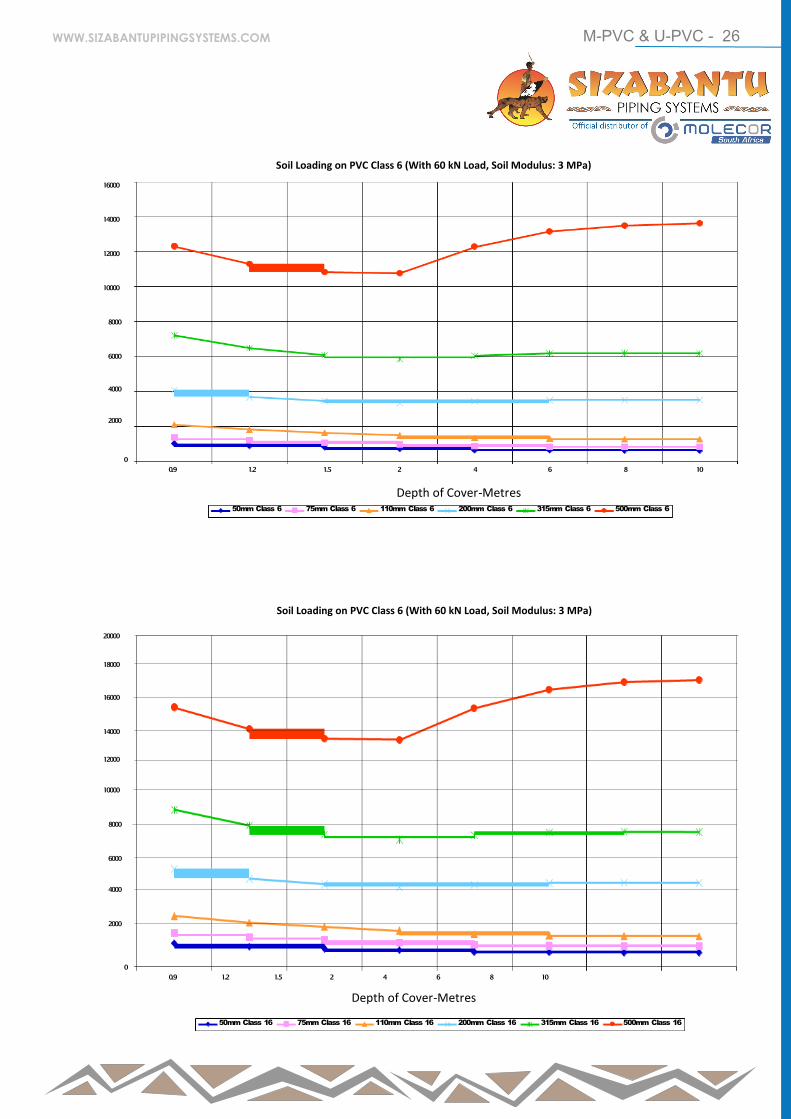
The Soil Loading graphs below show that,
after initial rapid increases with increased
depth, this rate of increase falls away to
almost zero at depths of about 6 metres or
more. Typical maximum values of soil loads
(without live loads) are between 1000 and
17000 N/m (for sizes between 50 and 500mm),
depending largely on soil type, modulus and
pipe stiffness. As soil compaction is increased
so the maximum soil load on the pipe reduces,
assuming that backfilling procedures have
been followed.
Soil load at shallow depths increases
dramatically when a 60kN live load is added.
This effect is aggravated by poor compaction.
However, from about 3 metres deep this effect
becomes negligible.
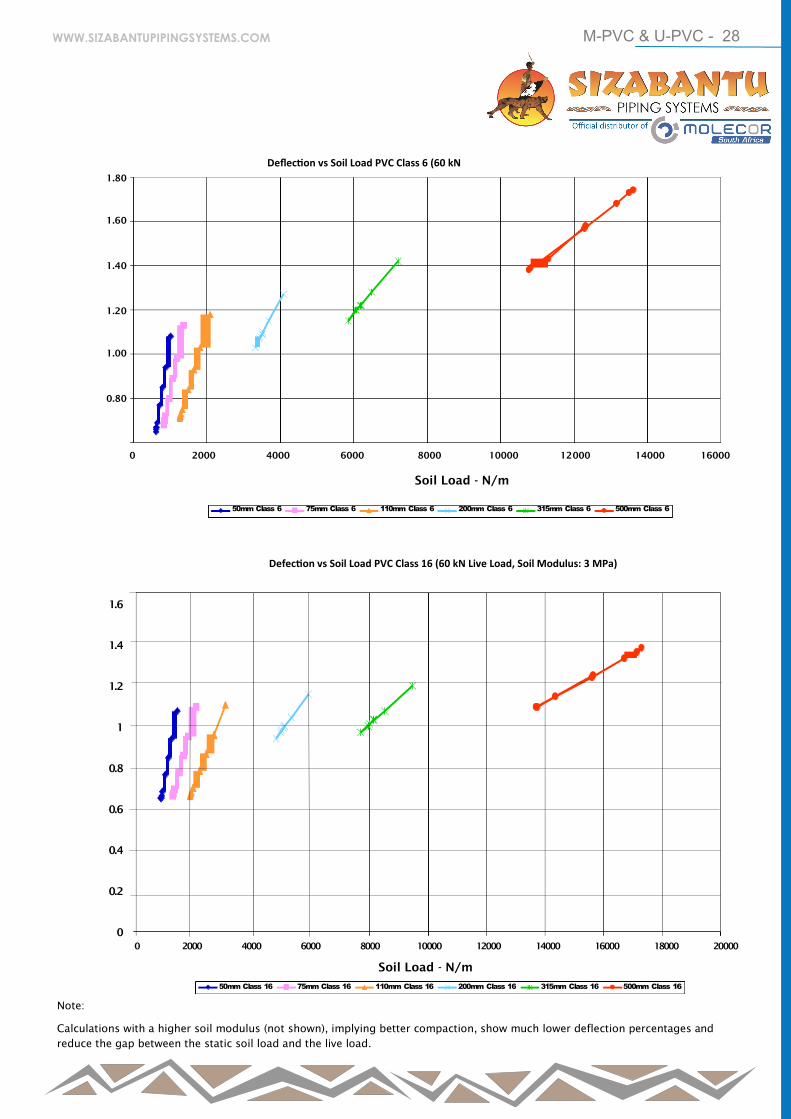
As can be seen from the Deflection vs. Soil
Load graph there is a straight line relationship
between deflection and soil load for each size
and class of pipe. Therefore if the soil load
reaches a maximum then the deflection also
has a maximum. These graphs include the
maximum soil loads from the soil load graphs
and shows the maximum deflection (for the
conditions represented) of less than 1.8% - for
a 500mm Class 6 pipe - even with a 60 kN live
load. Large diameter pipes carry more load
because of their greater surface area. Thicker
pipes carry more soil load because it is more
difficult to deflect since less load shedding
occurs.
The graphs below were based on calculations
using values typical for reasonable backfill
material which has been poorly compacted (soil
modulus of 3 MPa) excluding and including a 60
kN live load. Trench widths of 0.4m, 0.6m, 0.7m
and 0.8m were used for the following groups of
pipe sizes: 50mm -160mm, 200mm - 315mm,
400mm and 500mm. Different soil cover over
the pipes were used, varying from 0.9m to 10m.
The method of calculation was provided by
Professor David Stephenson of Witwatersrand
University.
We have shown graphs on the following pages
for class 6 and class16 only but have available
graphs for class 9 and class 12 which show
very similar trends. The graphs represent mPVC
pipes.
WWW.SIZABANTUPIPINGSYSTEMS.COM
M-PVC & U-PVC - 25
16000
14000
12000
10000
8000
6000
4000
2000
0
0 .9 1.2 1.5 2 4 6 8 10
50mm Class 6 75mm Class 6 110mm Class 6 200mm Class 6 315mm Class 6 500mm Class 6
20000
18000
16000
14000
12000
10000
8000
6000
4000
2000
0
0.9 1.2 1.5 2 4 6 8 10
50mm Class 16 75mm Class 16 110mm Class 16 200mm Class 16 315mm Class 16 500mm Class 16
Depth Of Cover-Metres
Depth Of Cover-Metres
Soil Loading on PVC Class 16 (No Live Load, Soil Modulus: 3 MPa)
Soil Loading on PVC Class 6 (No live Load, Soil
WWW.SIZABANTUPIPINGSYSTEMS.COM
M-PVC & U-PVC - 26
16000
14000
12000
10000
8000
6000
4000
2000
0
0.9 1.2 1.5 2 4 6 8 10
20000
18000
16000
14000
12000
10000
8000
6000
4000
2000
0
0.9 1.2 1.5 2 4 6 8 10
Soil Loading on PVC Class 6 (With 60 kN Load, Soil Modulus: 3 MPa)
Depth of Cover-Metres 50mm Class 6 75mm Class 6 110mm Class 6 200mm Class 6 315mm Class 6 500mm Class 6
Soil Loading on PVC Class 6 (With 60 kN Load, Soil Modulus: 3 MPa)
50mm Class 16 75mm Class 16 110mm Class 16 200mm Class 16 315mm Class 16 500mm Class 16
Depth of Cover-Metres
WWW.SIZABANTUPIPINGSYSTEMS.COM

M-PVC & U-PVC - 27
Deflection vs Soil Load PVC Class 6 (No Live
Soil Load - N/m
50mm Class 6 75mm Class 6 110mm Class 6 200mm Class 6 315mm Class 6 500mm Class 6
Deflection vs Soil Load PVC Class 16 (No Live Load, Soil Modulus: 3 MPa)
50mm Class 16 75mm Class 16 110mm Class 16 200mm Class 16 315mm Class 16 500mm Class 16
Soil Load - N/m
1.80
1.60
1.40
1.20
1.00
0.80
0.60
0.40
0.20
0 2000 4000 6000 8000 10000 12000 14000 16000 18000
0 2000 4000 6000 8000 10000 12000 14000 16000 18000 20000
1.4
1.2
1
0.8
0.6
0.4
0.2
0
WWW.SIZABANTUPIPINGSYSTEMS.COM
M-PVC & U-PVC - 28
Deflection vs Soil Load PVC Class 6 (60 kN
Soil Load - N/m
50mm Class 6 75mm Class 6 110mm Class 6 200mm Class 6 315mm Class 6 500mm Class 6
Defection vs Soil Load PVC Class 16 (60 kN Live Load, Soil Modulus: 3 MPa)
50mm Class 16 75mm Class 16 110mm Class 16 200mm Class 16 315mm Class 16 500mm Class 16 Soil Load - N/m
1.80
1.60
1.40
1.20
1.00
0.80
0 2000 4000 6000 8000 10000 12000 14000 16000
0 2000 4000 6000 8000 10000 12000 14000 16000 18000 20000
1.6
1.4
1.2
1
0.8
0.6
0.4
0.2
0
Note:
Calculations with a higher soil modulus (not shown), implying better compaction, show much lower deflection percentages and
reduce the gap between the static soil load and the live load.
WWW.SIZABANTUPIPINGSYSTEMS.COM
M-PVC & U-PVC - 29
Bending
An important feature of PVC pipes is that
they may be deliberately bent, within limits,
thus eliminating the need, in some cases, for
separate bends. As a rule of thumb the radius
of such a bend must not be less than 300 times the pipe
diameter. In addition each rubber ring joint can accom-
modate a further ½° of bend. This feature significantly
reduces costs and speeds up installation times when co
pared to some traditional pipe materials.
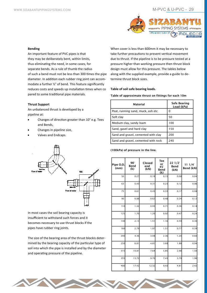
Thrust Support
An unbalanced thrust is developed by a
pipeline at:
Changes of direction greater than 10° e.g. Tees
and Bends,
Changes in pipeline size,
Valves and Endcaps.
In most cases the soil bearing capacity is
insufficient to withstand such forces and it
becomes necessary to use thrust blocks if the
pipes have rubber ring joints.
The size of the bearing area of the thrust blockis deter-
mined by the bearing capacity of the particular type of
soil into which the pipe is installed and by the diameter
and operating pressure of the pipeline.
When cover is less than 600mm it may be necessary to
take further precautions to prevent vertical movement
due to thrust. If the pipeline is to be pressure tested at a
pressure higher than working pressure then thrust block
design must allow for this pressure. The tables below
along with the supplied example, provide a guide to de-
termine thrust block sizes.
Table of soil safe bearing loads.
Table of approximate thrust on fittings for each 10m
(100kPa) of pressure in the line.
Material Safe Bearing
Load (kPa)
Peat, running sand, muck, ash etc 0
Soft clay 50
Medium clay, sandy loam 100
Sand, gavel and hard clay 150
Sand and gravel, cemented with clay 200
Sand and gravel, cemented with rock 240
Pipe O.D.
(mm)
90°
Bend
(k)
Closed
end
(kN)
Tee
or
45°
Bend
(k)
22 1/2°
Bend
(kN)
11 1/4°
Bend (kN)
50 0.27 0.19 0.15 0.08 0.04
63 0.43 0.31 0.23 0.12 0.06
75 0.61 0.43 0.33 0.17 0.08
90 0.88 0.62 0.48 0.24 0.12
110 1.32 0.93 0.71 0.36 0.18
125 1.70 1.20 0.92 0.47 0.24
140 2.13 1.51 1.16 0.59 0.30
160 2.79 1.97 1.51 0.77 0.39
200 4.36 3.08 2.36 1.20 0.60
250 6.81 4.81 3.68 1.88 0.94
315 10.81 7.64 5.85 2.98 1.50
355 13.72 9.70 7.43 3.79 1.90
400 17.42 12.32 9.43 4.81 2.42
WWW.SIZABANTUPIPINGSYSTEMS.COM
M-PVC & U-PVC - 30
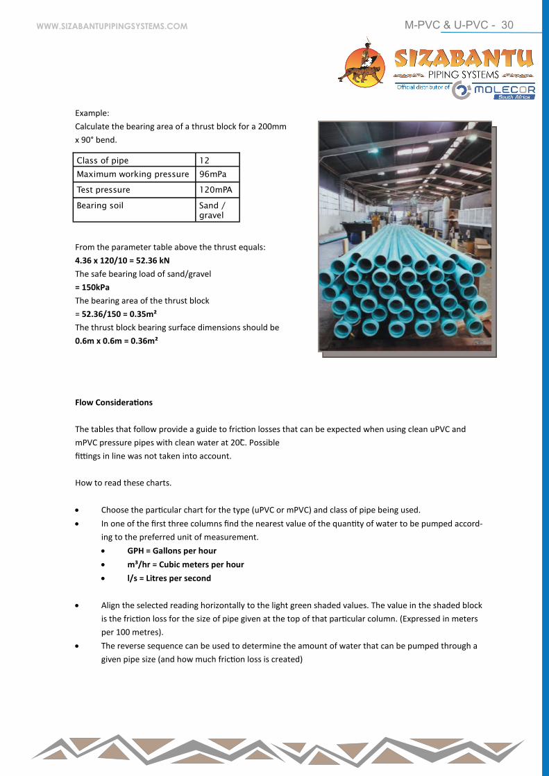
Example:
Calculate the bearing area of a thrust block for a 200mm
x 90° bend.
From the parameter table above the thrust equals:
4.36 x 120/10 = 52.36 kN
The safe bearing load of sand/gravel
= 150kPa
The bearing area of the thrust block
= 52.36/150 = 0.35m²
The thrust block bearing surface dimensions should be
0.6m x 0.6m = 0.36m²
Class of pipe 12
Maximum working pressure 96mPa
Test pressure 120mPA
Bearing soil Sand /
gravel
Flow Considerations
The tables that follow provide a guide to friction losses that can be expected when using clean uPVC and
mPVC pressure pipes with clean water at 20C̊. Possible
fittings in line was not taken into account.
How to read these charts.
Choose the particular chart for the type (uPVC or mPVC) and class of pipe being used.
In one of the first three columns find the nearest value of the quantity of water to be pumped accord-
ing to the preferred unit of measurement.
GPH = Gallons per hour
m³/hr = Cubic meters per hour
l/s = Litres per second
Align the selected reading horizontally to the light green shaded values. The value in the shaded block
is the friction loss for the size of pipe given at the top of that particular column. (Expressed in meters
per 100 metres).
The reverse sequence can be used to determine the amount of water that can be pumped through a
given pipe size (and how much friction loss is created)
WWW.SIZABANTUPIPINGSYSTEMS.COM
M-PVC & U-PVC - 31
Selection of Pipe Size and Class
Nominal bore of SABS 966 Pipes (mm)
Class 4 6 9 12 16 20 25
Working Pressure kPa 4
0
0
600 900 1200 1600 2000 2500
Test Pressure 1.25
*
Pressure Class (SABS
1200)
kPa
5
0
0
750
1125
1500
2000
2500
3125
Outside Diameter
(mm)
uPVC mP
VC
uPVC mPVC uPVC mPVC uPVC mPVC uPVC mPVC uPVC mPVC uPVC mPVC
16 13 - 13 - 13 - 13 - 13 - 13 - - -
20 17 - 17 - 17 - 17 - 17 - 16 - - -
25 22 - 22 - 22 - 22 - 21 - 20 - - -
32 30 - 29 - 29 - 28 - 27 - 25 - - -
40 38 - 37 - 36 - 35 - 34 - 32 - - -
50 48 - 46 47 45 47 44 46 42 45 40 44 - 43
63 60 - 59 60 57 60 55 58 53 57 51 56 - 54
75 71 - 70 72 68 71 66 70 63 68 60 66 - 65
90 85 - 84 86 82 85 79 84 76 82 72 79 - 78
110 - - 104 105 102 104 99 102 96 100 92 98 89 95
125 - - 119 120 116 118 113 116 109 114 104 111 101 108
140 - - 133 134 129 133 126 130 122 127 118 124 113 121
160 - - 152 153 148 151 144 149 139 145 134 142 129 138
200 - - 190 192 185 190 180 186 174 182 168 178 161 173
250 - - 237 240 231 237 225 233 218 227 210 222 201 216
315 - - 299 302 291 299 264 293 274 287 - 280 - -
355 - - 337 340 328 337 320 331 309 323 - 316 - -
400 - - 380 384 370 379 360 373 348 364 - 356 - -
450 - - 427 431 416 427 405 419 - 410 - 400 - -
500 - - 475 479 463 474 451 466 - 455 - 444 - -
WWW.SIZABANTUPIPINGSYSTEMS.COM