mq power dca-60ssi2 whisperwatttm … drain plug - removing the coolant drain plug while the engine...
TRANSCRIPT

© C
OP
YR
IGH
T 2
001,
MU
LTIQ
UIP
IN
C.
PARTS AND OPERATION MANUAL
MULTIQUIP INC. PARTS DEPARTMENT:18910 WILMINGTON AVE. 800-427-1244CARSON, CALIFORNIA 90746 FAX: 800-672-7877310-537-3700 SERVICE DEPARTMENT:800-421-1244 800-835-2551FAX: 310-537-3927 FAX: 310-638-8046E-mail:[email protected] • www:multiquip.com
PARTS AND OPERATION MANUAL
MQ POWERDCA-60SSI2
WHISPERWATTTM
GENERATOR
PARTS LIST NO. 8081500G
REV. #3 (09/15/01)

PAGE 2 — DCA-60SSI2 — PARTS AND OPERATION MANUAL — REV. #3 (09/15/01)

DCA-60SSI2 — PARTS AND OPERATION MANUAL— REV. #3 (09/15/01) — PAGE 3
HERE'S HOW TO GET HELPPLEASE HAVE THE MODEL AND SERIAL NUMBERON-HAND WHEN CALLING
PPPPPARARARARARTS DEPTS DEPTS DEPTS DEPTS DEPARARARARARTMENTTMENTTMENTTMENTTMENT800/427-1244 or 310/537-3700FAX: 800/672-7877 or 310/637-3284
SERSERSERSERSERVICE DEPVICE DEPVICE DEPVICE DEPVICE DEPARARARARARTMENTTMENTTMENTTMENTTMENT800/835-2551 or 310/537-3700FAX: 310/638-8046
WWWWWARRANTY DEPARRANTY DEPARRANTY DEPARRANTY DEPARRANTY DEPARARARARARTMENTTMENTTMENTTMENTTMENT800/835-2551 or 310/537-3700FAX: 310/638-8046
MAINMAINMAINMAINMAIN800/421-1244 or 310/537-3700FAX: 310/537-3927

PAGE 4 — DCA-60SSI2 — PARTS AND OPERATION MANUAL — REV. #3 (09/15/01)
TABLE OF CONTENTS
Here's How To Get Help ........................................... 3Table Of Contents .................................................... 4Parts Ordering Procedures ...................................... 5Rules for Safe Operation ......................................... 6-9Towing and Transportation ....................................... 10Trailer Safety Guidelines .......................................... 11-17Trailer Wiring Diagram .............................................. 18Electric Brake Troubleshooting ................................ 19Hydraulic Brake Troubleshooting .............................. 20Operation Decals ..................................................... 21-22DCA -60SSI2 Specifications ................................... 23General Information ................................................. 24Major Components .................................................. 55Dimensions .............................................................. 26Control Panel Descriptions ...................................... 28-29Engine Operating Panel Descriptions ...................... 30-31Output Terminal Panel Descriptions ......................... 32-33Output Amperage Setup .......................................... 34-35Output Voltage Setup ............................................... 36-39Installation ............................................................... 40-41Pre Set-up ............................................................... 42-45Load Application ...................................................... 46Generator Start-up Procedure ................................. 47-49Generator Shut-down Procedure .............................. 50Maintenance ............................................................ 52-55Generator Wiring Diagram ........................................ 56Engine Wiring Diagram ............................................ 57Engine Troubleshooting ............................................ 58-59Generator/Engine Troubleshooting ........................... 60Explanation of Codes in Remarks Column .............. 62Suggested Spare Parts ........................................... 63
MQ POWER DCA-60SSI2AC GENERATORGenerator Assembly ................................................ 64-65Control Box Assembly ............................................. 66-67Engine & Radiator Assembly ................................... 68-71Engine Operating Panel Assembly .......................... 72-75Battery Assembly .................................................... 76-77Muffler Assembly .................................................... 78-79Fuel Tank Assembly ................................................ 80-81Enclosure Assembly ............................................... 82-85Rubber Seal Assembly ............................................ 86-87Name Plate And Decals .......................................... 88-89
ISUZU 6BG1 ENGINECylinder Head Cover Assembly ............................ 90-91Cylinder Head Assembly ...................................... 92-93Cylinder Block Assembly ..................................... 94-97Oil Pan and Level Gauge Assembly ..................... 98-99Camshaft and Valve Assembly ............................. 100-101Crankshaft Piston and Flywheel Assembly .......... 102-103Timing Gear and Flywheel Housing Assembly ..... 104-105Inlet Manifold Assembly ....................................... 106-107Exhaust Manifold Assembly ................................. 108-109Ventilation Assembly ............................................ 110-111Water Pump and Corrosion Resistor Assembly .... 112-113Thermostat and Housing Assembly ..................... 114-115Engine Water Piping Assembly ............................. 116-117Fan and Fan Belt Assembly ................................. 118-119Fuel Injection Assembly ....................................... 120-121Fuel Filter and Bracket Assembly ........................ 122-123Fuel Pump and Pipe Assembly ............................ 124-125Oil Cooler and Oil Filter Assembly ....................... 126-127Oil Pump and Oil Strainer Assembly .................... 128-129Oil and Vacuum Piping Assembly ........................ 130-131Electrical Control Assembly ................................. 132-133Starter Components Assembly ............................ 134-135Alternator Components Assembly ........................ 136-137Injection Pump Components Assembly ............... 138-141Governor Components Assembly ......................... 142-145Feed Pump Assembly .......................................... 146-147Misc. Injection Pump Assembly ........................... 148-149Coupling Assembly ............................................... 150-151Water Sedimenter Assembly ................................ 152-153Switch and Relay Assembly ................................. 154-155
Terms and Condition of Sale — Parts .................. 156
NOTE
Specification and part numberSpecification and part numberSpecification and part numberSpecification and part numberSpecification and part numberare subject to change withoutare subject to change withoutare subject to change withoutare subject to change withoutare subject to change withoutnoticenoticenoticenoticenotice.....

DCA-60SSI2 — PARTS AND OPERATION MANUAL— REV. #3 (09/15/01) — PAGE 5
PARTS ORDERING PROCEDURES
Get special freight allowanceswhen you order 10 or moreline items via FAX!**� UPS Ground Service at no charge for freight
� PS Third Day Service at one-half of actual freight cost
No other allowances on freight shipped by any other carrier.
**Common nuts, bolts and washers (all items under $1.00 list price)do not count towards the 10+ line items.
*DISCOUNTS ARE SUBJECT TO CHANGE*
Fax order discount and UPS special programs revised June 1, 1995
For faxed orders only
UPSSpecial
Earn Extra Discounts whenyou order by FAX!
All parts orders which include complete part numbersand are received by fax qualify for the following extradiscounts:
Number ofline items ordered Additional Discount1-9 items 3%
10+ items** 5%
Now! Direct TOLL-FREE accessto our Parts Department!
Toll-free nationwide: 800-421-1244Toll-free FAX:
800/6-PARTS-7 • 800-672-7877
� Dealer account number� Dealer name and address� Shipping address (if different than billing address)� Return fax number� Applicable model number� Quantity, part number and description of each part� Specify preferred method of shipment:
• UPS Ground
• UPS Second Day or Third Day*
• UPS Next Day*
• Federal Express Priority One (please provide us with your FederalExpress account number)*
• Airborne Express*
• Truck or parcel post
*Normally shipped the same day the order is received, if prior to 2PM west coast time.
Extra Fax Discount
for Domestic USA
Dealers Only

PAGE 6 — DCA-60SSI2 — PARTS AND OPERATION MANUAL — REV. #3 (09/15/01)
RULES FOR SAFE OPERATION
� NEVER touch the hot exhaustmanifold, muffler or cylinder. Allowthese parts to cool before servicingengine or generator.
� The engine of this generator requires an adequate freeflow of cooling air. Never operate the generator in anyenclosed or narrow area where free flow of the air isrestricted. If the air flow is restricted it will cause seriousdamage to the generator or engine and may cause injuryto people. The generator engine gives off DEADLY carbonmonoxide gas.
� High Temperatures – Allow the engine to cool beforeadding fuel or performing service and maintenancefunctions. Contact with hot components can cause seriousburns.
Failure to follow instructions in this manualmay lead to serious injury or even death!This equipment is to be operated by trainedand qualified personnel only! This equipmentis for industrial use only.
The following safety guidelines should always be used whenoperating the DCA-60SSI2 portable generator:
GENERAL SAFETY
� DO NOT operate or service this equipment beforereading this entire manual.
� This equipment should not be operated bypersons under 18 years of age.
� NEVER operate this equipment without properprotective clothing, shatterproof glasses, steel-toed boots and other protective devicesrequired by the job.
� NEVER operate this equipment when not feelingwell due to fatigue, illness or taking medicine.
� NEVER operate this equipment under theinfluence or drugs or alcohol.
� NEVER use accessories or attachments, which are notrecommended by MQ Power for this equipment. Damageto the equipment and/or injury to user may result.
� Manufacturer does not assume responsibility for anyaccident due to equipment modifications.
� Whenever necessary, replace nameplate, operation andsafety decals when they become difficult read.
� Always check the machine for loosened threads or boltsbefore starting.
CAUTION:
� Always use extreme caution whenworking with flammable liquids. Whenrefueling, stop the engine and allow itto cool. DO NOT smoke around or nearthe machine. Fire or explosion couldresult from fuel vapors, or if fuel is spilledon a hot engine.
� NEVER operate the generator in anexplosive atmosphere or near combustiblematerials. An explosion or fire could resultcausing severe bodily harm or evendeath.
� Topping-off to filler por t isdangerous, as it tends to spill fuel.
� Always refuel in a well-ventilated area,away from sparks and open flames.
CAUTION:

DCA-60SSI2 — PARTS AND OPERATION MANUAL— REV. #3 (09/15/01) — PAGE 7
RULES FOR SAFE OPERATION
CAUTION:
� Backfeed to a utility system can cause electrocution and/or property damage. Do not connect to any building'selectrical system except through an approved device orafter building main switch is opened.
Never use damaged or worn cables whenconnecting power tools or equipment to thegenerator. Make sure power connectingcables are securely connected to thegenerator’s output terminals, insufficienttightening of the terminal connections maycause damage to the generator andelectrical shock.
CAUTION:DO NOT touch or open any of the belowmentioned components while thegenerator is running. Always allowsufficient time for the engine and generatorto cool before performing maintenance.
Radiator
1. Radiator Cap - Removing the radiator cap while theengine is hot will result in high pressurized, boiling waterto gush out of the radiator, causing severe scalding toany persons in the general area of the generator.
2. Coolant Drain Plug - Removing the coolant drain plugwhile the engine is hot will result in hot coolant to gushout of the coolant drain plug, therefore causing severescalding to any persons in the general area of thegenerator.
3. Engine Oil Drain Plug - Removing the engine oil drainplug while the engine is hot will result in hot oil to gushout of the oil drain plug, therefore causing severescalding to any persons in the general area of thegenerator.
CAUTION:
CAUTION:
� NEVER touch output terminals during operation. This isextremely dangerous. Always stop the machine whencontact with the output terminals is required.

PAGE 8 — DCA-60SSI2 — PARTS AND OPERATION MANUAL — REV. #3 (09/15/01)
RULES FOR SAFE OPERATION
� NEVER Run engine without air filter. Severe enginedamage may occur.
� Always service air cleaner frequently to prevent carburetormalfunction.
� Always disconnect the battery before performing serviceon the generator.
� Always be sure the operator is familiar with proper safetyprecaution s and operations techniques before usinggenerator.
� Always store equipment properly when not in use.Equipment should be stored in a clean, dry location out ofthe reach of children.
� DO NOT leave the generator running in the manual modeunattended.
� DO NOT allow unauthorized people to operate thisequipment.
� Always read, understand, and follow procedures inOperator’s Manual before attempting to operate equipment.
� Refer to the Isuzu Engine Owner's Manual Isuzu Engine Owner's Manual Isuzu Engine Owner's Manual Isuzu Engine Owner's Manual Isuzu Engine Owner's Manual for enginetechnical questions or information.
Loading and Unloading (Crane)
� Before lifting, make sure the generator's lifting hook issecure and that there is no apparent damage to thegenerator itself (loose screws, nuts and bolts). If anypart is loose or damaged, please take corrective actionbefore lifting.
� Always drain fuel prior to lifting.
� Always make sure crane or lifting device has beenproperly secured to the hook of guard frame on generator.
� NEVER lift the machine while the engine is running.
� Use adequate lifting cable (wire or rope) of sufficientstrength.
� When lifting the generator, always use the balancedcenter-point suspension hook and lift straight upwards.
� NEVER allow any person or animal to stand underneaththe machine while lifting.
� When loading the generator on a truck, be sure to usethe front and back frame bars as a means to secure thegenerator during transport.
Battery
Never over fill the battery with water abovethe upper limit.
CAUTION:
The battery contains acids that can cause injury to the eyesand skin. To avoid eye irritation, always wear safety glasses.Use well insulated gloves when picking up the battery. Usethe following guidelines when handling the battery:
1. DO NOT drop the battery. There is the possibility of riskthat the battery may explode.
2. DO NOT expose the battery to open flames, sparks,cigarettes etc. The battery contains combustible gasesand liquids. If these gases and liquids come in contactwith a flame or spark, an explosion could occur.
3. Always keep the battery charged. If the battery is notcharged a buildup of combustible gas will occur.
4. Always keep battery charging and booster cables in goodworking condition. Repair or replace all worn cables.
5. Always recharge the battery in an open air environment,to avoid risk of a dangerous concentration of combustiblegases.
6. In case the battery liquid (dilute sulfuric acid) comes incontact with clothing or skinclothing or skinclothing or skinclothing or skinclothing or skin, rinse skin or clothingimmediately with plenty of water.
7. In case the battery liquid (dilute sulfuric acid) comes incontact with your eyes, rinse eyes immediately withplenty of water, then contact the nearest doctor or hospital,and seek medical attention.

DCA-60SSI2 — PARTS AND OPERATION MANUAL— REV. #3 (09/15/01) — PAGE 9
Transporting� Always shutdown engine before transporting.
� Tighten fuel tank cap securely.
� Drain fuel when transporting generator over long distancesor bad roads.
� Always tie-down the generator during transportation bysecuring the generator.
� If generator is mounted on a trailer, make sure trailercomplies with all local and state safety transportationlaws. See page 10 for basic towing procedures.
Emergencies
� Always know the location of the nearest fire extinguisherfire extinguisherfire extinguisherfire extinguisherfire extinguisherand first aid kitfirst aid kitfirst aid kitfirst aid kitfirst aid kit. Know the location of the nearest telephone.Also know the phone numbers of the nearest ambulanceambulanceambulanceambulanceambulance,doctordoctordoctordoctordoctor and fire departmentfire departmentfire departmentfire departmentfire department.
RULES FOR SAFE OPERATION
Maintenance Safety� NEVER lubricate components or attempt service on a
running machine.
� Always allow the machine a proper amount of time tocool before servicing.
� Keep the machinery in proper running condition.
� Fix damage to the machine immediately and alwaysreplace broken parts.
� Dispose of hazardous waste properly. Examples ofpotentially hazardous waste are used motor oil, coolant,fuel, and fuel filters.
� DO NOT use plastic containers to dispose of hazardouswaste.
� DO NOT pour waste, oil, coolant or fuel directly onto theground, down a drain or into any water source.

PAGE 10 — DCA-60SSI2 — PARTS AND OPERATION MANUAL — REV. #3 (09/15/01)
To reduce the possibility of an accidentwhile transporting the generator on public roads, alwaysmake sure the trailer (Figure 1) that supports the generatorand the towing vehicle are in good operating condition andboth units are mechanically sound.
The following list of suggestions should be used when towingyour generator:
CAUTION :Towing Safety Precautions
Check with your county or state safetytowing regulations department before towingyour generator.
� Make sure the hitch and coupling of the towing vehicleare rated equal to, or greater than the trailer "gross vehicleweight rating" (GVWR).
� ALWAYS inspect the hitch and coupling for wear. NEVERtow a trailer with defective hitches, couplings, chainsetc.
� Check the tire air pressure on both towing vehicle andtrailer. Also check the tire tread wear on both vehicles.
� ALWAYS make sure the trailer is equipped with a "SafetyChain".
DCA-60SSI2 — TOWING RULES FOR SAFE OPERATION
� ALWAYS attach trailer’s safety chain to bumper of towingvehicle.
� ALWAYS make sure the vehicle and trailer directional,backup, brake, and trailer lights are connected andworking properly.
� The maximum speed for highway towing is 45 MPHunless posted otherwise. Recommended off-road towingis not to exceed 10 MPH or less depending on type ofterrain.
� Place chocked blocks underneath wheel to preventrolling, while parked.
� Place support blocks underneath the trailer’s bumper toprevent tipping, while parked.
� Use the trailer’s hand winch to adjust the height of thetrailer, then insert locking pin to lock wheel stand in place,while parked.
� Avoid sudden stops and starts. This can cause skidding,or jack-knifing. Smooth, gradual starts and stops willimprove gas milage.
� Avoid sharp turns to prevent rolling.
� Remove wheel stand when transporting.
� DO NOT transport generator with fuel in tank.
Figure 1. Generator with Trailer

DCA-60SSI2 — PARTS AND OPERATION MANUAL— REV. #3 (09/15/01) — PAGE 11
Explanation of Chart:This section is to provide the user with trailer service andmaintenance information. The service and maintenanceguidelines referenced in this section apply a wide range oftrailers. Remember periodic inspection of the trailer will en-sure safe towing of the equipment and will prevent damageto the equipment and personal injury.
It is the purpose of this section to cover the major mainte-nance components of the trailer. The following trailer com-ponents will be discussed in this section:
BrakesTiresLug Nut TorquingSuspensionElectricalBrake Troubleshooting Tables
Use the following definitions with reading Table 1.1. Fuel Cell - Provides an adequate amount of fuel for the
equipment in use. Fuel cells must be empty when trans-porting equipment.
2. Braking System - System employed in stopping thetrailer. Typical braking systems are electric, surge, hy-draulic, hydraulic-surge and air.
3. GVWR- Gross Vehicle Weight Rating (GVWR), is themaximum number of pounds the trailer can carry, in-cluding the fuel cell (empty).
DCA-60SSIU — TRAILER-SAFETY GUIDELINES
4. Frame Length - This measurement is from the ballhitch to the rear bumper (reflector).
5. Frame Width - This measurement is from fender tofender.
6. Jack Stand - Trailer support device with maximumpound requirement from the tongue of the trailer.
7. Coupler - Type of hitch used on the trailer for towing.8. Tire Size - Indicates the diameter of the tire in inches
(10,12,14, etc.), and the width in millimeters(175,185,205, etc.). The tire diameter must match thediameter of the tire rim.
9. Tire Ply - The tire ply (layers) number is rated in letters;2-ply,4-ply,6-ply, etc.
10. Wheel Hub - The wheel hub is connected to the trailer’saxle.
11. Tire Rim - Tires mounted on a tire rim. The tire rim mustmatch the size of the tire.
12. Lug Nuts - Used to secure the wheel to the wheel hub.Always use a torque wrench to tighten down the lugnuts. See Table 4 and Figure 5 or lug nut tightening andsequence.
13. Axle - Indicates the maximum weight the axle can sup-port in pounds, and the diameter of the axle expressedin inches (see Table 3). Please not that some trailershave a double axle. This will be shown as 2-6000 lbs.,meaning two axles with a total weight capacity of 6000pounds.
14. Suspension - Protects the trailer chassis from shockstransmitted through the wheels. Types of suspensionused are leaf, Q-flex, and air ride.
15. Electrical - Electrical connectors (looms) are providedwith the trailer so the brake lights and turn signals canbe connected to the towing vehicle.
16. Application - Indicates which units can be employedon a particular trailer.
CAUTION:ALWAYS make sure the trailer is in goodoperating condition. Check the tires forproper inflation and wear. Also check thewheel lug nuts for proper tightness.

PAGE 12 — DCA-60SSI2 — PARTS AND OPERATION MANUAL — REV. #3 (09/15/01)
snoitacificepS.1elbaT
LEDOM NOITACILPPA LEUFLLEC
EKARBMETSYS
RWVG EMARFHTGNEL
EMARFHTDIW
KCAJDNATS
W01-RLRT ,522WDS003WLT,052WGS
ON ON SBL0091 "69 "05 .BL008LEEHWTLITLLUF
01-RLRT ,21GLT,01ACD51-ACD
ON ON SBL0091 "69 "05 .BL008LEEHWTLITLLUF
FX01-RLRT ,21-GLT,01ACD003-WLT,51ACD
LAG25 ON SBL0091 "69 "05 .BL008LEEHWTLITLLUF
W522-RLRT ,SREDLEWSS0007AD
ON ON SBL0022 "58 "24 .BL008LEEHWTLITLLUF
004WLB-RLRT 004-WLB ON CIRTCELE SBL0072 "451TSAM/W"421O/W
"55)LLAT"87(
.BL008LEEHWTLITLLUF
X05-RLRT 52-ACD ON ON SBL0072 "421 "55 .BL008LEEHWTLITLLUF
FX05-RLRT 52-ACD LAG14 ON SBL0072 "421 "55 .BL008LEEHWTLITLLUF
W07-RLRT 07,06-,54-ACD ON EGRUS SBL0007 "681 "77 .BL0002DAPTALF
X07-RLRT 07,06-,54-ACD TPO EGRUS SBL0007 "831 "66 .BL0002DAPTALF
FX07-RLRT 07,06-,54-ACD LAG35 EGRUS SBL0007 "831 "66 .BL0002DAPTALF
FX001-RLRT 521,001-ACD LAG051 EGRUSCILUARDYH SBL0007 "091 "67 .BL0002DAPTALF
521/58-RLRT ,001,58-ACD521
LAG541 CILUARDYH SBL00001 "681 "77 .BL0002DAPTALF
FX051-RLRT 081,051-ACD LAG002 EGRUSCILUARDYH SBL06111 "402 "48 .BL0005DAPTALF
FX022-RLRT 022-ACD LAG052 EGRUSCILUARDYH SBL00041 "222 "38 .BL0005DAPTALF
FX003-RLRT 003-ACD LAG052 EGRUSCILUARDYH SBL00081 "832 "38 .BL0005DAPTALF
FX004-RLRT 004-ACD LAG053 CIRTCELE SBL00081 "832 "38 .BL0005DAPTALF
FX006-RLRT 008,006-ACD LAG055 RIA SBL00003 "483 "69 .BL0005DAPTALF
XS008-RLRT 008,006-ACD LAG055 RIA SBL00003 "483 "69 .BL0005DAPTALF
DCA-60SSIU —TRAILER-SPECIFICATIONS

DCA-60SSI2 — PARTS AND OPERATION MANUAL— REV. #3 (09/15/01) — PAGE 13
)t'noC(snoitacificepS.1elbaT
LEDOM RELPUOC SERIT SLEEHW ELXA SBUH NOISNEPSUS LACIRTCELE
W01-RLRT SSALCLLAB"2ELBATSUJDA2
C31-571 "05.4X"31 2X2#0022 GUL5 FAEL3 /WMOOLERIW4TALFELOP4
01-RLRT SSALCLLAB"2ELBATSUJDA2
C31-571 "5.4X"31 2X2#0022 GUL5 FAEL3 TALFELOP4
FX01-RLRT SSALCLLAB"2ELBATSUJDA2
C31-571 "5.4X"31 2X2#0022 GUL5 FAEL3 TALFELOP4
W522-RLRT SSALCLLAB"2ELBATSUJDA2
B31-571 "5.4X31 2X2#0022 GUL5 XELFQ TALFELOP4
WLB-RLRT004
SSALCLLAB"2ELBATSUJDA2
C31-571 "5.4X31 2X2#0022 GUL5 FAEL3 TALFELOP4
X05-RLRT SSALCLLAB"2 CRL31-87B "05.4X"31 .sbl0053"8/3-2
GUL5 FAEL4 REBBURELOP4TALF
FX05-RLRT SSALCLLAB"2 CRL31-87B "05.4X"31 .sbl0053"8/3-2
GUL5 FAEL4 REBBURELOP4TALF
W07-RLRT SSALCLLAB"2ELBATSUJDA"3
C41-502)4(SAIB
"5X"41 .sbl0053"3
GUL5 FAEL5 REBBURELOP4TALF
X07-RLRT SSALCLLAB"2ELBATSUJDA"3
C41-502)4(SAIB
"5X"41 sbl0053"3
GUL5 FAEL5 REBBURELOP4TALF
FX07-RLRT SSALCLLAB"2ELBATSUJDA"3
C41-502)4(SAIB
"5X"41 .sbl0053"3
GUL5 FAEL5 REBBURELOP4TALF
FX001-RLRT 6/5-2ELBATSUJDAEYE"3TPO
C51-502)4(SAIB
"5.5X"41 sbl0053"3
GUL5 FAEL5 MOOLERIW4
521/58-RLRT 6/5-2ELBATSUJDAEYE"3TPO
D51R57/522TS)4(LAIDAR
"6x"41 sbl0006-)2( GUL6 FAEL7 MOOLERIW4
FX051-RLRT EYELLAB"3 E61-057)4(SAIB
"7X"61 sbl0006-)2( GUL8 FAEL7 MOOLERIW4
FX022-RLRT EYE"3ELBATSUJDA
E61R58/532TS)4(LAIDAR
"7X"61 sbl0007-)2( GUL8 XELFQ MOOLERIW4
FX003-RLRT EYE"3ELBATSUJDA
E61R58/532TS)6(LAIDAR
"7X"61 sbl0006-)2( GUL8 XELFQ MOOLERIW4
FX004-RLRT EYE"3ELBATSUJDA
E61R58/532TS)6(LAIDAR
"7X"61 .sbl0007-)3( GUL8 XELFQ MOOLERIW4
FX006-RLRT LEEHWHT5 H5.71R57/512TS)8(LAIDAR
"7X"61 sbl00001-)3( GUL8 FAEL7 MOOLERIW6
RA008-RLRT LEEHWHT5 H5.71R57/512TS)8(LAIDAR
"7X"61 sbl00001-)3( GUL8 EDIR-RIA MOOLERIW6
DCA-60SSIU —TRAILER-SPECIFICATIONS

PAGE 14 — DCA-60SSI2 — PARTS AND OPERATION MANUAL — REV. #3 (09/15/01)
DCA-60SSIU —TRAILER SAFETY GUIDELINES
BrakesIf your trailer has a braking system, the brakes should beinspected the first 200 miles of operation. This will allowthe brake shoes and drums to seat properly. After the first200 mile interval, inspect the brakes every 3,000 miles. Ifdriving over rough terrain, inspect the brakes morefrequently.
Electric BrakesElectrically actuated brakes (Figure 2) are similar tohydraulic brakes. The basic difference is that hydraulicbrakes are actuated by an electromagnet.Listed below are some of the advantages that electricbrakes have over hydraulic brakes:
Brake system can be manually adjusted to providethe corrected braking capability for varying road andload conditions
Brake system can be modulated to provide more orless braking force, thus easing the brake load on thetowing vehicle
Brake system has very little lag time between the timethe vehicle’s brakes are actuated and the trailer’s brakesare actuated
Brake system can provide an independent emergencybrake system
Remember in order to properly synchronize the tow vehicle’sbraking to the trailer’s braking, can only be accomplishedby road testing. Brake lockup, grabbiness or harshness isdue to lack of synchronization between the tow vehicleand the trailer being towed or under-adjusted brakes.
Before any brake synchronizations adjustments can bemade, the trailer brakes should be burnished-in by applyingthe brakes 20-30 times with approximately a 20 m.p.h.decrease in speed, e.g. 40 m.p.h. to 20 m.p.h. Allow ampletime for brakes to cool between application. This allowsthe brake shoes to slightly be seated into the brake drumsurface.
Figure 2 displays the major electric brake components thatwill require inspection and maintenance. Please inspectthese components as required.
Electric Brake Adjustment1. Place the trailer on jack stands. Make sure the jack
stands are placed on secure level ground.2. Check the wheel and drum for free rotation.3. Remove the adjusting hole cover from the adjusting
slot at the bottom brake backing plate.4. With a screwdriver or standard adjusting tool, rotate
the star wheel of the adjuster assembly to expand thebrake shoes.
5. Adjust the brake shoes outward until the pressure ofthe lining against the wheel drum makes the wheeldifficult to turn.
6. Rotate the star wheel in the opposite direction until thewheel rotates freely with slight lining drag.
7. Replace the adjusting hole cover and lower the trailerto the ground.
8. Repeat steps 1 through 6 on the remaining brakes.

DCA-60SSI2 — PARTS AND OPERATION MANUAL— REV. #3 (09/15/01) — PAGE 15
DCA-60SSIU — TRAILER SAFETY GUIDELINES
Hydraulic/Air/Surge BrakesHydraulic brakes (Figure 3) should not require any specialattention with the exception of routine maintenance suchas shoe and lining replacement. These brakes can beadjusted in the same manner as electric brakes. Brakelines should be periodically checked for cracks, kinks, orblockage.
Figure 3 below displays the major hydraulic/air/surge brakecomponents that will require inspection and maintenance.Please inspect these components as required using steps1 through 6 as referenced in the electric brake adjustmentssection.
Figure 2. Electrical Brake Components
Figure 3. Hydraulic Brake Components

PAGE 16 — DCA-60SSI2 — PARTS AND OPERATION MANUAL — REV. #3 (09/15/01)
Tires/Wheels/Lug NutsTires and wheels are a very impor tant and criticalcomponents of the trailer. When specifying or replacing thetrailer wheels it is important the wheels, tires, and axle areproperly matched.
CAUTION:DO NOT attempt to repair or modify awheel. DO NOT install in inner tube tocorrect a leak through the rim. If the rimis cracked, theair pressure inthe inner tube
may cause pieces of the rim toexplode (break off) with great forceand cause serious eye or bodilyinjury.
Tire Wear/InflationTire inflation pressure is the most important factor in tire life.Pressure should be checked cold before operation DO NOTbleed air from tires when they are hot. Check inflationpressure weekly during use to insure the maximum tire lifeand tread wear.Table 2 (Tire Wear Troubleshooting) will help pinpoint thecauses and solutions of tire wear problems.
CAUTION:
NOTE
ALWAYS wear safety glasses when removingor installing force fitted parts. Failure to complymay result in serious injury.
SuspensionThe leaf suspension springs and associated components(Figure 4) should be visually inspected every 6,000 miles forsigns of excessive wear, elongation of bolt holes, andloosening of fasteners. Replace all damaged parts(suspension) immediately. Torqued suspension componentsas detailed in Table 3.
DCA-60SSIU — TRAILER SAFETY GUIDELINES
Figure 4. Major Suspension Components

DCA-60SSI2 — PARTS AND OPERATION MANUAL— REV. #3 (09/15/01) — PAGE 17
stnemeriuqeReuqroTnoisnepsuS.3elbaT
metI ).sbL-.tF(euqroT
TLOB-U"8/3 53-XAM03-NIM
TLOB-U"61/7 06-XAM54-NIM
TLOB-U"2/1 06-XAM54-NIM
SHACKLE BOLT
SPRING EYE BOLT
SNUG FIT ONLY. PARTS MUST ROTATE FREELY.LOCKING NUTS OR COTTER PINS ARE PROVIDED TO
RETAIN NUT-BOLT ASSEMBLY.
SHOULDER TYPE
SHACKLE BOLT
05-XAM03-NIM
stnemeriuqeReuqroTeriT.4elbaT
eziSleehW ssaPtsriFSBL-TF
ssaPdnoceSSBL-TF
ssaPdrihTSBL-TF
"21 52-02 04-53 56-05
"31 52-02 04-53 56-05
"41 52-02 06-05 021-09
"51 52-02 06-05 021-09
"61 52-02 06-05 021-09
Lug Nut Torque RequirementsIt is extremely important to apply and maintain proper wheelmounting torque on the trailer. Be sure to use only thefasteners matched to the cone angle of the wheel. Properprocedure for attachment of the wheels is as follows:
1. Start all wheel lug nuts by hand.2. Torque all lug nuts in sequence. See Figure 5. DO NOT
torque the wheel lug nuts all the way down. Tighteneach lug nut in 3 separate passes as defined by Table 4.
3. After first road use, retorque all lug nuts in sequence.Check all wheel lug nuts periodically.
NOTE
NEVER use an pneumatic air gun totighten wheel lug nuts.
DCA-60SSIU —TRAILER SAFETY GUIDELINES
Figure 5. Wheel Lug Nuts Tightening Sequence

PAGE 18 — DCA-60SSI2 — PARTS AND OPERATION MANUAL — REV. #3 (09/15/01)
NOTE:LIGHTS ARE ORIENTED FROM THE DRIVER’S SEAT
DCA-60SSIU —TRAILER-WIRING DIAGRAM

DCA-60SSI2 — PARTS AND OPERATION MANUAL— REV. #3 (09/15/01) — PAGE 19
gnitoohselbuorTekarBcirtcelE.5elbaT
motpmyS esuaCelbissoP noituloS
sekarBtnettimretnIrosekarBoN ?seriwnekorbrostiucricnepoynA .tcerrocdnadniF
?stiucrictrohsynA .tcerrocdnadniF
?rellortnocytluaF .tcerrocdnatseT
?snoitcennocesoolynA .riaperdnadniF
?eruceseriwdnuorG .erucesdnadniF
otlluPsekarBrosekarBkaeWediSenO
?sgninilrostengamnolioroesaerG .ecalperronaelC
?dedorrocsnoitcennoC esuactcerrocdnanaelC.noisorrocfo
?devoorgroderocssmurdekarB .ecalperroenihcaM
?dezinorhcnyssekarB .tcerroC
sekarBgnikcoL ?nekorbrotneb,esoolstnenopmocekarB .stnenopmocecalpeR
?dnuor-fo-tuosmurdekarB .ecalpeR
sekarBysioN ?detacirbulmetsyS .etacirbuL
?tcerrocstnenopmocekarB .tcerrocdnaecalpeR
sekarBgniggarD ?detsujdaleehwehtfosgniraeB .tsujdA
DCA-60SSIU —TRAILER-BRAKE TROUBLESHOOTING

PAGE 20 — DCA-60SSI2 — PARTS AND OPERATION MANUAL — REV. #3 (09/15/01)
gnitoohselbuorTekarBciluardyH.6elbaT
motpmyS esuaCelbissoP noituloS
sekarBoN ?deknikronekorbenilekarB .ecalperroriapeR
otlluPsekarBrosekarBkaeWediSenO
?dezalggninilekarB .ecalperrohsinrubeR
?dedaolrevoreliarT .thgiewtcerroC
?devoorgroderocssmurdekarB .ecalperroenihcaM
?tcerrocerusserperiT .yllauqeseritllaetalfnI
?elxaemasehtnodehctamnuseriT .serithctaM
sekarBgnikcoL ?nekorbrotneb,esoolstnenopmocekarB .stnenopmocecalpeR
?dnuor-fo-tuosmurdekarB .ecalpeR
sekarBysioN ?detacirbulmetsyS .etacirbuL
?tcerrocstnenopmocekarB .tcerrocdnaecalpeR
sekarBgniggarD thgirnirotcerrocssenkcihtgninilekarB?noitisopgnorw
dnaseohswenllatsnI.sgninil
?diulftcerrocrodiulfekarbhguonE straprebburecalpeR.diulf4todhtiwllif
DCA-60SSIU —TRAILER-BRAKE TROUBLESHOOTING

DCA-60SSI2 — PARTS AND OPERATION MANUAL— REV. #3 (09/15/01) — PAGE 21
DCA-60SSI2 — GENERATOR DECALS
The DCA -100SSJU generator is wquipped with a number of safety decals. These decals are provided for operator safetyand maintenance information. The illustration below and on the preceding pages show the decals as they appear on themachine. Should any of these decals become unreadable, replacements can be obtained from your dealer.

PAGE 22 — DCA-60SSI2 — PARTS AND OPERATION MANUAL — REV. #3 (09/15/01)
DCA-60SSI2 — GENERATOR DECALS
DCA-60SSI2 — PARTS AND OPERATION MANUAL— REV. #3 (09/15/01) — PAGE 23
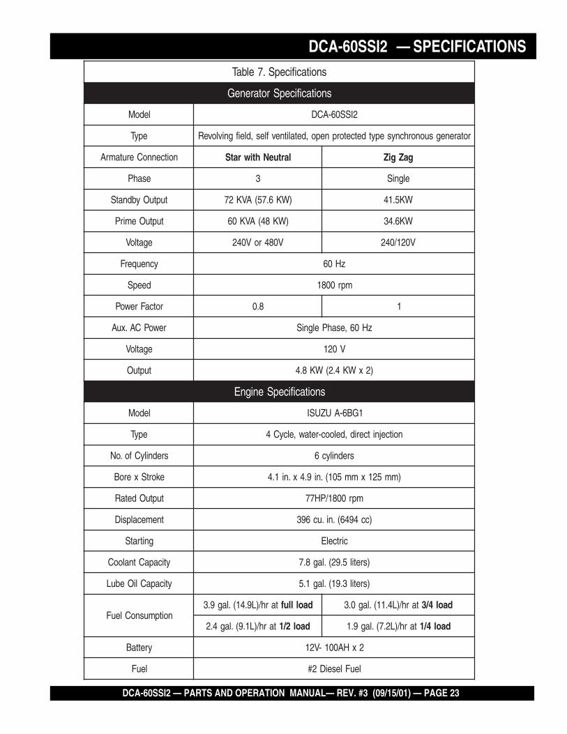
DCA-60SSI2 — SPECIFICATIONSsnoitacificepS.7elbaT
snoitacificepSrotareneG
ledoM 2ISS06-ACD
epyT rotarenegsuonorhcnysepytdetcetorpnepo,detalitnevfles,dleifgnivloveR
noitcennoCerutamrA lartueNhtiwratS gaZgiZ
esahP 3 elgniS
tuptuOybdnatS )WK6.75(AVK27 WK5.14
tuptuOemirP )WK84(AVK06 WK6.43
egatloV V084roV042 V021/042
ycneuqerF zH06
deepS mpr0081
rotcaFrewoP 8.0 1
rewoPCA.xuA zH06,esahPelgniS
egatloV V021
tuptuO )2xWK4.2(WK8.4
snoitacificepSenignE
ledoM 1GB6-AUZUSI
epyT noitcejnitcerid,delooc-retaw,elcyC4
srednilyCfo.oN srednilyc6
ekortSxeroB )mm521xmm501(.ni9.4x.ni1.4
tuptuOdetaR mpr0081/PH77
tnemecalpsiD )cc4946(.ni.uc693
gnitratS cirtcelE
yticapaCtnalooC )sretil5.92(.lag8.7
yticapaCliOebuL )sretil3.91(.lag1.5
noitpmusnoCleuFtarh/)L9.41(.lag9.3 daollluf tarh/)L4.11(.lag0.3 daol4/3
tarh/)L1.9(.lag4.2 daol2/1 tarh/)L2.7(.lag9.1 daol4/1
yrettaB 2xHA001-V21
leuF leuFleseiD2#

PAGE 24 — DCA-60SSI2 — PARTS AND OPERATION MANUAL — REV. #3 (09/15/01)
DCA-60SSI2 — GENERAL INFORMATION
DCA-60SSI2 FAMILIARIZATION
Generator
The MQ Power Model DCA-60SSI2 is a 48 kW genergenergenergenergeneratoratoratoratoratorthat is designed as a high quality portable (requires a trailerfor transport) power source for telecom sites, lightingfacilities, power tools, submersible pumps and otherindustrial and construction machinery.
Engine Operating Panel
The “Engine Operating Panel” is provided with the following:TachometerWater Temperature GaugeOil Pressure GaugeCharging Ammeter GaugeEngine Throttle LeverPanel LightPanel Light SwitchOil Pressure and WaterTemp. Indicator lights
Generator Control Panel
The “Generator Control Panel” is provided with the following:Output Voltage Adjustment KnobFrequency Meter (Hz)AC Ammeter (Amps)AC Voltmeter (Volts)Ammeter Change-Over SwitchVoltmeter Change-Over Switch
Output Terminal Panel
The “Output Terminal Panel” is provided with the following:Three 120/240V output receptacles, 50 ampTwo 120V input receptacles, 20 amp3 Load Circuit Breakers 240V @50 amps2 Load GFCI Circuit Breakers 120V@ 20amps
Control Box
The “Control Box” is provided with the following:Main Circuit Breaker 150 ampsOver-Current Relay
Engine
The DCA-60SSI2 is powered by a 4 cycle, water cooled,Isuzu A-6BG1diesel diesel diesel diesel diesel engine. This engine is designed tomeet every performance requirement for the generator.Reference Table 1, page13 for engine specifications.
In keeping with Multiquip's policy of constantly improvingits products, the specifications quoted herein are subject tochange without prior notice.
The basic controls and indicators for the DCA-60SSI2generator are addressed on the following pages.
Mechanical Governor SystemThe mechanical governor system control the RPM of theengine. When the engine demands increase or decrease,the mechanical governor system regulates the frequencyvariation to ±1.5%. The electronic governor option in-creases frequency variation to ±.25%.
Open Delta Excitation System
The DCA-60SSI2 generator is equipped with the state ofthe art "Open-DeltaOpen-DeltaOpen-DeltaOpen-DeltaOpen-Delta" excitation system. The open deltasystem consist of an electrically independent winding woundamong stationary windings of the AC output section.
There are four leads: A, B, C and D. During light loads, thepower to the AAAAAutomatic utomatic utomatic utomatic utomatic VVVVVoltage Regulator oltage Regulator oltage Regulator oltage Regulator oltage Regulator (AVR) is suppliedfrom the leads parallel connections of B&C. When loadsincrease, the AVR switches and accepts power from leadsA&D. The output of leads A&D increase proportionally withload. This of adding the voltages to each phase providesbetter voltage response during heavy loads.
The connections of the AVR to the AC output windings arefor sensing only. No power is required from these windings.
The open-delta design provides virtually unlimited excitationcurrent, offering maximum motor starting capabilities. Theexcitation does not have a "fixed ceilingfixed ceilingfixed ceilingfixed ceilingfixed ceiling" and respondsaccording the demands of the required load.

DCA-60SSI2 — PARTS AND OPERATION MANUAL— REV. #3 (09/15/01) — PAGE 25
DCA-60SSI2 — MAJOR COMPONENTS
Figure 6. Major Components

PAGE 26 — DCA-60SSI2 — PARTS AND OPERATION MANUAL — REV. #3 (09/15/01)
DCA-60SSI2 — DIMENSIONS (TOP, SIDE AND FRONT)
Figure 7. Dimensions

DCA-60SSI2 — PARTS AND OPERATION MANUAL— REV. #3 (09/15/01) — PAGE 27
NOTE PAGE

PAGE 28 — DCA-60SSI2 — PARTS AND OPERATION MANUAL — REV. #3 (09/15/01)
DCA-60SSI2 — CONTROL PANEL
Figure 8. Control Panel

DCA-60SSI2 — PARTS AND OPERATION MANUAL— REV. #3 (09/15/01) — PAGE 29
DCA-60SSI2 — CONTROL PANEL
The definitions below describe the controls and functions ofthe DCA-60SSI2 " Control Panel Control Panel Control Panel Control Panel Control Panel " (Figure 8).
1. Frequency Meter – Indicates the output frequency inhertz (Hz). Normally 60 Hz ±1 Hz .
2. AC Ammeter – Indicates the amount of current theload is drawing from the generator.
3. ACVoltmeter – Indicates the single phase outputvoltage present at the UNV terminals.
4. Pilot Lamp - This lamp indicates the load is not properlyset. Readjust the load, or use the voltmeter change-over switch to adjust phase position.
5. Main Circuit Breaker – This three-pole, 150 amp mainbreaker is provided to protect the UNV voltage outputterminals from overload.
6. Voltmeter Change-Over Switch – This switch allowsthe AC voltmeter to indicate phase to phase voltagebetween any two phases of the output terminals or tobe switched off.
7. Ammeter Change-Over Switch – This switch allowsthe AC ammeter to indicate the current flowing to theload connected to any phase of the output terminals, orto be switched off.
8. Voltage Regulator Control – Allows manualadjustment of the generator’s output voltage.

PAGE 30 — DCA-60SSI2 — PARTS AND OPERATION MANUAL — REV. #3 (09/15/01)
DCA-60SSI2 — ENGINE OPERATING PANEL
Figure 9. Engine Operating Panel

DCA-60SSI2 — PARTS AND OPERATION MANUAL— REV. #3 (09/15/01) — PAGE 31
The definitions below describe the controls and functions ofthe DCA-60SSI2 " Engine Operating Panel Engine Operating Panel Engine Operating Panel Engine Operating Panel Engine Operating Panel " (Figure 9).
1. Oil Pressure Gauge – Normal operation should be about25 psi. When starting the generator the oil pressuremay read a bit higher, but after the engine warms upthe oil pressure should return to normal.
2. Panel light - Normally used in dark places or at night.When activated, panel will luminate. When the generatoris not in use, turn the panel light switch to the ‘OFF’position.
3. Water Temperature Gauge – During normal operationthis gauge be should read between 165o to 215o.
DCA-60SSI2 — ENGINE OPERATING PANEL
4. Charging Ammeter Gauge – Indicates the currentbeing supplied by the engine’s alternator which providescurrent for generator’s control circuits and batterycharging system.
5. Indicator Lights - These lights indicate if the oilpressure or water temperature is at dangerous levelsand will shut off the engine. The oil pressure indicatorwill initially light at start-up, but will go off once thepressure rises.
6. Panel light switch- When activiated, will turn on controlpanel light.
7. Lamp Check Switch - This is used to check theindicator lights. Turn on the engine, then press this tocheck the bulbs. If they don’t light, replace the bulbs.
8. Engine Throttle Lever - Pull or push this lever to changethe speed of the engine when a load is applied.
9. Pre-Heat Indicator – Under cold conditions, turn thestarter key to preheat. Once the indicator lights, theengine is ready to start.
10. Starter Switch - Turn this to start, stop, and preheatthe engine.
11. Tachometer – Indicates engine speed in RPM’s for 60Hz operation. This meter should indicate 1800 RPM’swhen the engine is at full speed and a load is applied.In addition, a built in hour meter will record the numberof operational hours that the generator has been in use.

PAGE 32 — DCA-60SSI2 — PARTS AND OPERATION MANUAL — REV. #3 (09/15/01)
DCA-60SSIU — OUTPUT TERMINAL PANEL
Output Terminal PanelThe output control panel is located on the rear (control panel)end of the generator. The UNV lugs are protected by a faceplate cover that can be secured in the close position by apad lock.
120 Volt ReceptacleOne GFCI Duplex NEMA 5-20R (120V, 20 Amp) receptacleis located on the output terminal. This receptacle can beused anytime the generator is in operation. The receptacleis controlled by the circuit breaker located on the controlpanel.The reset button will reset the receptacle after being tripped.Pressing the :Test Button” (Figure 8) in the center of thisreceptacle will check the GFCI function. The receptacleshould be tested at least once a month.
Figure 10. GFCI Test Button
Connecting LoadLoads can be connected to the generator by the UVWO lugs orthe duplex receptacles. (See figure 3). Make sure to read theoperation manual before attempting to connect a load to thegenerator.
Maximum OutputThe entire load connected to the UVWO lugs, all four slots inthe duplex receptacles, and the must not exceed 52.8 kW instandby or 48 kW in prime output.
Generator GroundingMake sure to ground the generator in EVERY applicationprior to connecting a load. Generators are NOT groundedjust because they are mounted on trailers or other vehiclesthat are on rubber tires.
Twist Lock Dual Voltage Receptacles - To use thesereceptacles, place the voltage selector switch in the singlephase 240/120 voltage position and adjust the outputvoltage to 240 volts with the voltage regulator on theControl Panel (Figure 8, page 28). Place the voltmeterchange-over switch to the U-W position and the ammeterchange-over switch to the U or W to read the output.
Circuit Breakers
To protect the generator from an overload, a 3-pole, 150 amp,main main main main main circuit breaker is provided to protect the UVWO outputterminals from overload. In addition two single-pole, 20 ampGFCIGFCIGFCIGFCIGFCI circuit breakers are provided to protect the GFCIreceptacles from overload. Three 50 amp loadloadloadloadload circuitbreakers have also been provided to protect the load side ofthe generator from overload. Make sure to switch ALLALLALLALLALL circuitbreakers to the "OFF" position prior to starting the engine.
Generator GroundingMake sure the generator is properly grounded beforeapplying load. Generators are NOT considered groundedwhen mounted on a trailer.
Figure 11. Load Application

DCA-60SSI2 — PARTS AND OPERATION MANUAL— REV. #3 (09/15/01) — PAGE 33
DCA-60SSIU — OUTPUT TERMINAL VOLTAGE SELECTION
DCA-60SSIU
Legs O and Ground areconsidered Bonded Grounds.
NOTE
Figure 12. Output Panel Location

PAGE 34 — DCA-60SSI2 — PARTS AND OPERATION MANUAL — REV. #3 (09/15/01)
elbaliavAegatloV.8elbaT
esahP3)elbahctiwS(
TLOV802 TLOV022 TLOV042 TLOV614 TLOV044 TLOV084
esahPelgniS)elbahctiwS(
TLOV021 TLOV721 TLOV931 TLOV042 TLOV452 TLOV772
Output Terminal Panel Available VoltagesA wide range of voltages are available to supply load tomany different applications. Voltages may be selected byusing the voltage selector switch and depending how youhookup your hard wire connection to the generator. To obtainsome of the voltages listed, fine adjustment with the voltageregulator on the control panel is necessary. See Table 8 foravailable voltages the generator will supply.
CAUTION :
NEVER switch Voltage Selector Switchposition while the engine is engaged.
Voltage Selector Switch Locking ButtonThe voltage selector switch has a locking button to protectthe generator and generator load from being switched whilethe engine is running. To lock the voltage selector switch,press in the red button located on the voltage selector switch,and use a pad lock to hold it into this position.
spmAmumixaM.9elbaT
detaRegatloV
spmAmumixaM
esahPelgniStloV021
)eriw4(spma3.331
esahPelgniStloV042
)eriw4(spma7.66
esahPeerhTtloV042
spma441
esahPeerhTtloV084
spma27
Maximum AmpsTable 9 shows the maximum amps the generator will pro-vide. Do not exceed the maximum amps listed.
Over Current RelayAn over current relay is connected to the circuit breaker.During an over current situation, both the circuit breaker andthe over current relay will trip. If the circuit breaker can notbe reset, the reset button on the over current relay must bepressed. The over current relay is located inside the controlbox.
DCA-60SSIU — OUTPUT AMPERAGE SETUP

DCA-60SSI2 — PARTS AND OPERATION MANUAL— REV. #3 (09/15/01) — PAGE 35
Receptacle UseWhen the UVWO terminals are providing power, the recep-tacle power availability will decrease.
How To Read The Output Terminal Gauges.The gauges (Figure 15 and 17) and change-over switcheson the control panel DO NOT effect the generator output.They are to help observe how much power is being suppliedat the UVWO legs.
When the voltage selector switch is in the 240/120V posi-tion (Figure 13), place the AC voltmeter change-over switchto the W-U position (Figure 14) and the AC ammeter change-over switch to the U or W position (Figure 16) to read theoutput on the selected leg.
Figure 13. Voltage Selector Switch 240/120V SinglePhase Position
Figure 14 and 15. AC Voltmeter Change-over switchand Voltmeter Gauge
Figure 16 and 17. AC Ammeter Change-over Switchand Ammeter Gauge
When using plural single phasevoltages, make sure to balancethe load on each of the singlephase legs.
NOTE
DCA-60SSIU — OUTPUT AMPERAGE SETUP

PAGE 36 — DCA-60SSI2 — PARTS AND OPERATION MANUAL — REV. #3 (09/15/01)
240/120V Hard Wire Hookup
With the voltage selector set and locked at ‘single phase240/120’ and using single phase 120 volts, the generatorwill provide three legs available with 100 amps each on threedifferent circuits (Figure 18).
480/240V Hard Wire Hookup
With the voltage selector set and locked at ‘3 phase 480/277’ (Figure 19) and using the 3-phase 240 hookup, it willprovide one circuit available at 108 amps with any two wiresplus the ground (Figure 20).
When using the 3-phase 480 volts hookup, it will provideone circuit available at 50 amps with all three wires plusground.
Figure 19. Voltage Selector Switch 480/277V Three PhasePosition
Figure 18. Hard Wire Hookup at 240/120V Position
Figure 20. Hard Wire Hookup at 480/240V Position
DCA-60SSIU — OUTPUT VOLTAGE SETUP

DCA-60SSI2 — PARTS AND OPERATION MANUAL— REV. #3 (09/15/01) — PAGE 37
Voltage Selector Switch- 3 Phase 480/277V PositionThe following are additional voltages available when the volt-age selector switch is in the ‘3 phase 480/277V’ position.
3 Phase, 480V, 440V, or 416 VoltThis setting can provide 3-phase power at 480, 440, or 416volts. After hooking up the hard wires to the lugs as shownin Figure 22, 480 volts can be obtained with the voltageregulator knob turned toward maximum; 440 volts can beobtained with the voltage regulator knob is turned down; and416 volts can be obtained with the voltage regulator knob isat the lowest setting.
Single Phase: 480V, 440V, or 416 VoltThis setting can provide single phase power at 480, 440, or416 volts. After hooking up the hard wires to the lugs asshown in Figure 23, 480 volts can be obtained with the volt-age regulator knob turned toward maximum; 440 volts canbe obtained with the voltage regulator knob is turned down;and 416 volts can be obtained with the voltage regulatorknob is at the lowest setting.
Single Phase: 277V, 254V, or 240VThis setting can provide single phase power at 277, 254, or240 volts. After hooking up the hard wires to the lugs asshown in Figure 24, 277 volts can be obtained with the volt-age regulator knob turned toward maximum; 254 volts canbe obtained with the voltage regulator knob is turned down;and 240 volts can be obtained with the voltage regulatorknob is at the lowest setting.
Figure 22. Hard Wire Hookup for Three Phase 480V, 440V, or416V
Figure 24. Hard Wire Hookup for Single Phase 277V, 254V,or 240V
Figure 23. Hard Wire Hookup for Single Phase 480V, 440V,or 416V
Figure 21. Voltage Regulator Knob
DCA-60SSIU — OUTPUT VOLTAGE SETUP
PAGE 38 — DCA-60SSI2 — PARTS AND OPERATION MANUAL — REV. #3 (09/15/01)
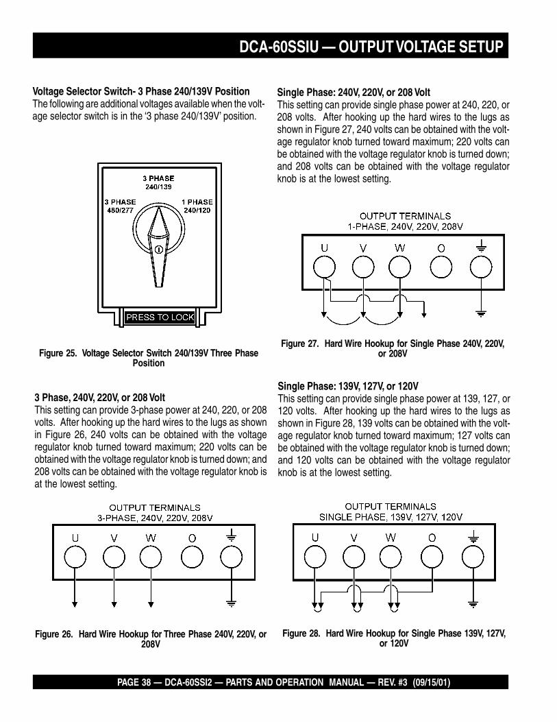
Voltage Selector Switch- 3 Phase 240/139V PositionThe following are additional voltages available when the volt-age selector switch is in the ‘3 phase 240/139V’ position.
3 Phase, 240V, 220V, or 208 VoltThis setting can provide 3-phase power at 240, 220, or 208volts. After hooking up the hard wires to the lugs as shownin Figure 26, 240 volts can be obtained with the voltageregulator knob turned toward maximum; 220 volts can beobtained with the voltage regulator knob is turned down; and208 volts can be obtained with the voltage regulator knob isat the lowest setting.
Single Phase: 240V, 220V, or 208 VoltThis setting can provide single phase power at 240, 220, or208 volts. After hooking up the hard wires to the lugs asshown in Figure 27, 240 volts can be obtained with the volt-age regulator knob turned toward maximum; 220 volts canbe obtained with the voltage regulator knob is turned down;and 208 volts can be obtained with the voltage regulatorknob is at the lowest setting.
Single Phase: 139V, 127V, or 120VThis setting can provide single phase power at 139, 127, or120 volts. After hooking up the hard wires to the lugs asshown in Figure 28, 139 volts can be obtained with the volt-age regulator knob turned toward maximum; 127 volts canbe obtained with the voltage regulator knob is turned down;and 120 volts can be obtained with the voltage regulatorknob is at the lowest setting.
Figure 25. Voltage Selector Switch 240/139V Three PhasePosition
Figure 26. Hard Wire Hookup for Three Phase 240V, 220V, or208V
Figure 27. Hard Wire Hookup for Single Phase 240V, 220V,or 208V
Figure 28. Hard Wire Hookup for Single Phase 139V, 127V,or 120V
DCA-60SSIU — OUTPUT VOLTAGE SETUP

DCA-60SSI2 — PARTS AND OPERATION MANUAL— REV. #3 (09/15/01) — PAGE 39
Voltage Selector Switch- Single Phase 240/120VPositionThe following are additional voltages available when the volt-age selector switch is in the ‘single phase 240/120V’ posi-tion.
Single Phase, 240 VoltThis setting can provide single phase power at 240 volts.After hooking up the hard wires to the lugs as shown inFigure 30, 240 volts can be obtained with the voltage regula-tor knob turned to fine tune.
Single Phase: 120 VoltThis setting can provide single phase power at 120 volts.After hooking up the hard wires to the lugs as shown inFigure 31, 120 volts can be obtained with the voltage regula-tor knob turned to fine tune.
Figure 29. Voltage Selector Switch 240/120V Single PhasePosition
Figure 30. Hard Wire Hookup for Single Phase 240 volt
Figure 31. Hard Wire Hookup for Single Phase, 120 volt
DCA-60SSIU — OUTPUT VOLTAGE SETUP

PAGE 40 — DCA-60SSI2 — PARTS AND OPERATION MANUAL — REV. #3 (09/15/01)
CAUTION :An electric shock may happen whenvibrators are used. Pay close attention tohandling when operating vibrators andalways use rubber boots and gloves toinsulate the body from electrical shock.
Generator Grounding
To guard against electrical shock and possible damage tothe equipment, it is important to provide a good EARTHground.
Article 250 (Grounding) of the National Electrical Code (NEC)provides guide lines for proper grounding and specifies thatthe cable ground shall be connected to the grounding systemof the building as close to the point of cable entry aspractical.
NEC articles 25064(b) a and 250-66 set the followinggrounding requirements:
1. Use one of the following wire types to connect thegenerator to earth ground.
a. Copper - 10 AWG (5.3 mm2) or larger.
b. Aluminum - 8 AWG (8.4 mm2) or larger.
2. When grounding the generator (Figure 32) connect theground cable between the lock washer and the nut onthe generator and tighten the nut fully. Connect the otherend of the ground cable to earth ground.
3. NEC article 250-52(c) specifies that the earth groundrod should be buried a minimum of 8 ft. into the ground.
DCA-60SSI2 — INSTALLATION
NOTEWhen connecting the generator to any buildingselectrical system ALWAYS consult with a licensedelectrician.
Outdoor Installation
Install the generator in a location where it will not be exposedto rain or sunshine. Make sure the generator is on securelevel ground so that it cannot slide or shift around. Alsoinstall the generator in a manner so that the exhaust will notbe discharged in the direction of nearby homes.
The installation site must be relatively free from moistureand dust. All electrical equipment should be protected fromexcessive moisture. Failure to do will result in deteriorationof the insulation and will result in short circuits and grounding.
Foreign materials such as dust, sand, lint and abrasivematerials have a tendency to cause excessive wear toengine and alternator parts.
CAUTION :Pay close attention to ventilation whenoperating the generator inside tunnels andcaves. The engine exhaust containsnoxious elements. Engine exhaust mustbe routed to a ventilated area.
Indoor Installation
Exhaust gases from diesel engines are extremely poisonous.Whenever an engine is installed indoors the exhaust fumesmust be vented to the outside. The engine should be installedat least two feet from any outside wall. Using an exhaustpipe which is too long or too small can cause excessiveback pressure which will cause the engine to heatexcessively and possibly burn the valves.
Mounting
The generator must be mounted on a solid foundation (suchas concrete) and set firmly on the foundation to isolatevibration of the generator when it is running. The generatormust set at least 6 inches above the floor or grade level (inaccordance to NFPA 110, Chapter 5-4.1). DO NOT removethe metal skids on the bottom of the generator. They are toresist damage to the bottom of the generator and to maintainalignment.

DCA-60SSI2 — PARTS AND OPERATION MANUAL— REV. #3 (09/15/01) — PAGE 41
Figure 32. Typical Generator Grounding Application
DCA-60SSI2 — INSTALLATION

PAGE 42 — DCA-60SSI2 — PARTS AND OPERATION MANUAL — REV. #3 (09/15/01)
General Inspection Prior to Operation
The DCA-60SSI2 generator has been thoroughly inspectedand accepted prior to shipment from the factory. However,be sure to check for damaged parts or components, or loosenuts and bolts, which could have occurred in transit.
Extension Cable
When electric power is to be provided to various tools orloads at some distance from the generator, extensioncords are normally used. Cables should be sized to allowfor distance in length and amperage so that the voltagedrop between the generator and point of use (load) is heldto a minimum. Use the Cable Selection Guide (Table 10)as a guide for selecting proper cable size.
Circuit Breakers
To protect the generator from an overload, a 3-pole, 150 amp,main main main main main circuit breaker is provided to protect the UNV outputterminals from overload. In addition two single-pole, 20 ampGFCIGFCIGFCIGFCIGFCI circuit breakers are provided to protect the GFCIreceptacles from overload. Three 50 amp loadloadloadloadload circuit breakershave also been provided to protect the load side of thegenerator from overload. Make sure to switch ALLALLALLALLALL circuitbreakers to the "OFF" position prior to starting the engine.
DCA-60SSI2 — PRE-SETUP
)noitarepOesahPelgniS,zH06(noitceleSelbaC.01elbaT
nitnerruCserepmA
sttaWnIdaoL htgneLelbaCelbawollAmumixaM
021tAstloV
042tAstloV
eriW01# eriW21# eriW41# eriW61#
5.2 003 006 .tf0001 .tf006 .tf573 .tf052
5 006 0021 .tf005 .tf003 .tf002 .tf521
5.7 009 0081 .tf053 .tf002 .tf521 .tf001
01 0021 0042 .tf052 .tf051 .tf001
51 0081 0063 .tf051 .tf001 .tf56
02 0042 0084 .tf521 .tf57 .tf05
.egatlovwolmorftlusernacegamadtnempiuqE:NOITUAC
ALWAYS consult with a licensedelectrician for correct extensioncord wire size.
NOTE

DCA-60SSI2 — PARTS AND OPERATION MANUAL— REV. #3 (09/15/01) — PAGE 43
Lubrication Oil
Fill the engine crankcase with lubricating oil through the fillerhole, but do not overfill. Make sure the generator is level.With the dipstick inserted all the way, but without being screwinto the filler hole, verify that the oil level is maintainedbetween the two notches (Figure 33) on the dipstick. SeeTable 11 for proper selection of engine oil.
FuelFill the fuel tank with clean and fresh diesel fuel.diesel fuel.diesel fuel.diesel fuel.diesel fuel. DO NOTfill the tank beyond capacity.
Pay attention to the fuel tank capacity when replenishingfuel. Refer to the fuel tank capacity listed on page 23,Specification Table 7.
The fuel tank cap must be closed tightly after filling. Handlefuel in a safety container. If the container does not have aspout, use a funnel. Wipe up any spilled fuel immediately.
DCA-60SSI2 — PRE-SETUP
Figure 33. Engine Oil Dipstick
When checking the engine oil, be sure to check if the oil isclean and viscous. If the oil is not clean, drain the oil byremoving the oil drain plug, and refill with the specified amountof oil as outlined in the Isuzu Engine Owner's Manual.
liOrotoMdednemmoceR.11elbaT
egnaRerutarepmeT liOepyT
F°32~F°401)C°5-~C°04(
03EAS
F°5~F°32)C°51-~C°5-(
03-W01EASro02EAS
)°51-(C°5woleB 03-W01EASroW01EAS
CAUTION:Never fill the fuel tank while the engine isrunning or in the dark. Diesel spillage ona hot engine can cause a fire orexplosion. If diesel spillage occurs, wipeup the spilled diesel completely toprevent fire hazards.
CoolantUse only drinkable tap water. If hard water or water withmany impurities is used, the inside of the engine and radiatormay become coated with deposits and cooling efficiencywill be reduced.
An anticorrosion additive added to the water will help preventdeposits and corrosion in the cooling system. See the enginemanual for further details.

PAGE 44 — DCA-60SSI2 — PARTS AND OPERATION MANUAL — REV. #3 (09/15/01)
DCA-60SSIU — PRE-SETUP
Day-to-day addition of coolant is done from the reserve tank.When adding coolant to the radiator, DO NOT remove theradiator cap until the unit has completely cooled. See Table12. for engine, radiator, and reserve tank coolant capacities.Make sure the coolant level in the reserve tank is alwaysbetween the "H" and the "L" markings.
CAUTION :When adding coolant or antifreeze to theradiator, do not remove the radiator capuntil the unit has completely cooled.
yticapaCtnalooC.21elbaT
rotaidaRdnaenignE )retiL5.92(.laG8.7
knaTevreseR )retiL2(.laG59.
Operation in Freezing WeatherWhen operating in freezing weather, be certain the properamount of antifreeze (Table 13) has been added.
serutarepmeTgnitarepOezeerF-itnA.31elbaT
%loVezeerF-itnA
tnioPgnizeerF tnioPgnilioB
C° F° C° F°
04 42- 21- 601 222
05 73- 43- 801 622
When the antifreeze is mixed withWhen the antifreeze is mixed withWhen the antifreeze is mixed withWhen the antifreeze is mixed withWhen the antifreeze is mixed withwwwwwateraterateraterater, the antifreez, the antifreez, the antifreez, the antifreez, the antifreeze mixing re mixing re mixing re mixing re mixing ratio matio matio matio matio mustustustustustbe less than 50%.be less than 50%.be less than 50%.be less than 50%.be less than 50%.
NOTE
Cleaning the Outer RadiatorThe engine may overheat if the radiator fins becomeoverloaded with dust or debris. Periodically clean the radiatorfins with compressed air. Cleaning inside the radiator isdangerous, so clean only with the engine turned off and thebattery disconnected.
Air CleanerPeriodic cleaning/replacement is necessary. Inspect it inaccordance with the Isuzu Engine Owner's Manual.
Fan Belt TensionA slack fan belt may contribute to overheating, or toinsufficient charging of the battery. Inspect the fan belt fordamage and wear and adjust it in accordance with the IsuzuEngine Owner's Manual.
The fan belt tension is proper if the fan belt bends 10 to 15mm (Figure 34) when depressed with the thumb as shownbelow. Never place hands near the belts or fan while thegenerator is running.
Figure 34. Fan Belt Tension
Never place hands near the belts or fanwhile the generator set is running.
CAUTION :
Adjusting Fan BeltIf the fan belt does not have the 10 to 15 mm defectionfollow the procedure below to adjust:Loosen the alternator adjusting plate and alternator moundingbolt.Pivot the alternator at the mounting bolt toward the engineleft or right until the belt reflects the proper tension.Tighten the mounting bolt and the adjusting bolt.

DCA-60SSI2 — PARTS AND OPERATION MANUAL— REV. #3 (09/15/01) — PAGE 45
DCA-60SSIU — PRE-SETUP
Battery Cable InstallationALWAYS be sure the battery cables (Figure 35) are properlyconnected to the battery terminals as shown below. The REDREDREDREDREDcable is connected to the positive terminal of the battery,and the BLACK cable is connected to the negative terminalof the battery.
CAUTION :
When connecting battery do the following:
1. DO NOT connect the battery cables to the batteryterminals when the key is in the ignition and is set in'START' mode. ALWAYS remove the key from theignition and the ignition switch is in the OFF positionwhen connecting the battery.
2. Place a small amount of grease around both batteryterminals. This will ensure a good connection and willhelp prevent corrosion around the battery terminals.
CAUTION :
Inadequate battery connections maycause poor starting of the generator, andcreate other malfunctions.
WiringInspect the entire generator for bad or worn electrical wiringor connections. If any wiring or connections are exposed(insulation missing) replace wiring immediately.
Piping and Hose ConnectionInspect all piping, oil hose, and fuel hose connections forwear and tightness. Tighten all hose clamps and check hosesfor leaks.
If any hose (fuel or oil) lines are defective replace themimmediately.Figure 35. Battery Connections
If the battery cable is connectedincorrectly, damage to the generator willoccur. Pay close attention to the polarityof the battery when connecting thebattery.
BatteryThis unit is of negative ground. DO NOT connect in reverse.Always maintain battery fluid level between the specifiedmarks. Battery life will be shortened, if the fluid level is notproperly maintained. Add only distilled water whenreplenishment is necessary. DO NOT over fill.
The battery is sufficiently charged if the specific gravity ofthe battery fluid is 1.28 (at 68° F). If the specific gravityshould fall to 1.245 or lower, it indicates that the battery isdead and needs to be recharged or replaced.
Check to see whether the battery cables are loose. Poorcontact may result in poor starting or malfunctions. Alwayskeep the terminals firmly tightened. Coating the terminalswith a thin film of grease will help to inhibit corrosion.
AlternatorThe polarity of the alternator is negative grounding type.When an inverted circuit connection takes place, the circuitwill be in short circuit instantaneously resulting the alternatorfailure.
Do not put water directly on the alternator. Entry of waterinto the alternator leads an electrolyte corrosion causing analternator failure.
Before charging the battery with an external electric source,be sure to disconnect the battery cables.

PAGE 46 — DCA-60SSI2 — PARTS AND OPERATION MANUAL — REV. #3 (09/15/01)
DCA-60SSI2 — LOAD APPLICATION
Single Phase Load
Always be sure to check the nameplate on the generatorand equipment to insure the wattage, amperage andfrequency requirements are satisfactorily supplied by thegenerator for operating the equipment.
Generally, the wattage listed on the nameplate of theequipment is its rated output. Equipment may require 130—150% more wattage than the rating on the nameplate, asthe wattage is influenced by the efficiency, power factor andstarting system of the equipment.
When the voltage selector switch is in single phase (240/120V position), place the AC voltmeter change-over switchto the U-W position and the AC ammeter change over-switchto the U or W position to read the ouput.
Motors and motor-driven equipment drawmuch greater current for starting thanduring operation.
An inadequate size connecting cable which cannot carrythe required load can cause a voltage drop which can burnout the appliance or tool and overheat the cable.
When connecting a resistance load such as anincandescent lamp or electric heater, a capacity of upto the generating set’s rated output (kW) can be used.
When connecting a fluorescent or mercury lamp, acapacity of up to the generating set’s rated output (kW)multiplied by 0.6 can be used.
When connecting an electric drill or other power tools,pay close attention to the required starting currentcapacity.
If wattage is not available on the equipment, approximatewattage may be determined by mulitplying the nameplatevoltage by the nameplate amperage for three-phase:WATTS =1.732 x VOLTAGE x AMPERAGE
daoLyBrotcaFrewoP.41elbaT
daoLfOepyT rotcaFrewoP
srotomnoitcudniesahp-elgniS 57.0-4.0
tnecsednacni,sretaehcirtcelEspmal 0.1
spmalyrucrem,spmaltnecseroulF 9.0-4.0
noitacinummoc,secivedcinortcelEtnempiuqe 0.1
slootrewopnommoC 8.0
NOTEIf wattage is not given on theequipment's name plate, approximatewattage may be determined bymultiplying nameplate voltage by thenameplate amperage.WATTS = VOLTAGE x AMPERAGE
The power factor of this generator is 1.0. See Table 14.below when connecting loads.
Before connecting this generator to anybuilding’s electrical system, a licensedelectrician must install an isolation(transfer) switch. Serious injury or deathmay result without this transfer switch.
CAUTION:
Three Phase LoadWhen calculating the power requirements for 3-phase poweruse the following equation:
CAUTION:
NOTEIf output (kVA) is not given on theequipment nameplate, approximateoutput may be determined bymultiplying voltage by amperage by

DCA-60SSI2 — PARTS AND OPERATION MANUAL— REV. #3 (09/15/01) — PAGE 47
WARNING:
Before Starting
Engine
1. Check the lubricating oil level prior to starting the engine.Make sure the generator is level. The oil level must bemaintained between two notches on the dipstick.
2. When there is not enough lubricating oil, fill the crankcasewith high grade motor oil. Use a high quality detergentoil classified CC or higher (See Table 11 on page 43).
3. Check the coolant level in the radiator and subtank.Replenish with antifreeze as necessary. Always maintainthe coolant level between the FULL and LOW markingson the coolant container. Be sure that the radiator cap isfastened securely.
4. Check the fuel level on the fuel gauge. If fuel is low, fillthe fuel tank with clean fresh unleaded automotive diesel.If diesel spillage occurs, completely wipe up the spilledfuel immediately.
Before Starting
Generator and Control PanelCAUTION:
1. Be sure to disconnect theelectrical load and switch the main, load main, load main, load main, load main, load and G.FG.FG.FG.FG.F.C.C.C.C.C.I..I..I..I..I.circuit breakers (Figure 12) to the “OFF” position prior tostarting the engine.
NEVER start the engine with themain,main,main,main,main, GFCI GFCI GFCI GFCI GFCI or loadloadloadloadload circuit breakersin the ON position.
The engine's exhaust contains harmfulemissions. A LA LA LA LA LWWWWWAAAAAYS YS YS YS YS ventilate theexhaust when operating inside tunnels,excavations or buildings. Direct exhaustaway from nearby personnel.
Figure 36. Main, GFCI andLoad Circuit Breakers
DCA-60SSI2 — GENERATOR START-UP PROCEDURE
2. Connect the load to the UVW terminals as shown inFigure 37. These terminals can be found on the outputterminal panel, (see page 22 Figure 6). To gain accessto the output terminals lift the UVW cover. Tightenterminal nuts securely to prevent load wires from slippingout.
Figure 37. UVW Terminal Lugs (Load)
NEGATIVE
POSTIVE
BATTERY
3. Connect the negative battery cable (BLACK) to thenegative post on the battery (Figure 38).
Figure 38. Battery Connections
PAGE 48 — DCA-60SSI2 — PARTS AND OPERATION MANUAL — REV. #3 (09/15/01)
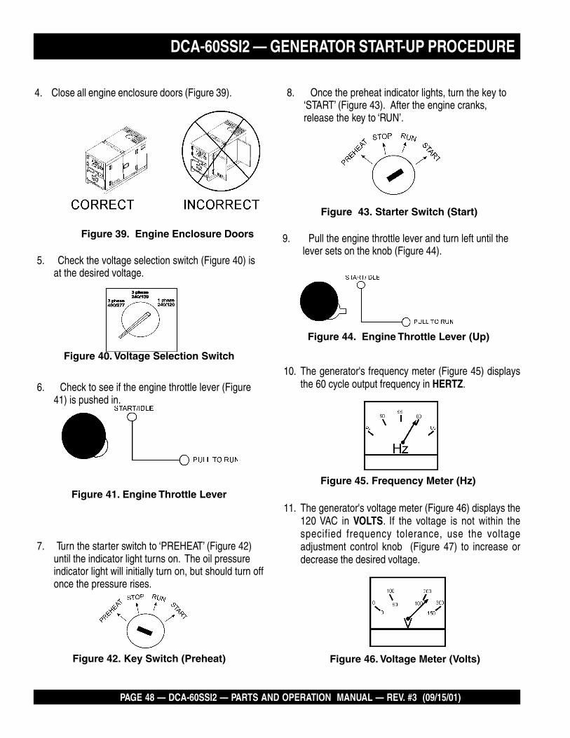
10. The generator's frequency meter (Figure 45) displaysthe 60 cycle output frequency in HERTZ.
Figure 46. Voltage Meter (Volts)
11. The generator's voltage meter (Figure 46) displays the120 VAC in VOLTS. If the voltage is not within thespecified frequency tolerance, use the voltageadjustment control knob (Figure 47) to increase ordecrease the desired voltage.
Figure 40. Voltage Selection Switch
4. Close all engine enclosure doors (Figure 39).
Figure 39. Engine Enclosure Doors
DCA-60SSI2 — GENERATOR START-UP PROCEDURE
5. Check the voltage selection switch (Figure 40) isat the desired voltage.
6. Check to see if the engine throttle lever (Figure41) is pushed in.
7. Turn the starter switch to ‘PREHEAT’ (Figure 42)until the indicator light turns on. The oil pressureindicator light will initially turn on, but should turn offonce the pressure rises.
8. Once the preheat indicator lights, turn the key to‘START’ (Figure 43). After the engine cranks,release the key to ‘RUN’.
Figure 41. Engine Throttle Lever
Figure 42. Key Switch (Preheat)
Figure 43. Starter Switch (Start)
Figure 45. Frequency Meter (Hz)
9. Pull the engine throttle lever and turn left until thelever sets on the knob (Figure 44).
Figure 44. Engine Throttle Lever (Up)

DCA-60SSI2 — PARTS AND OPERATION MANUAL— REV. #3 (09/15/01) — PAGE 49
A
0
40
60
75
20
Figure 48. Ammeter (No Load)
Figure 47. Voltage Adjust ControlKnob
12. The ammeter (Figure 48) will indicate zero amps with noload applied. When a load is applied, this meter willindicate the amount of current that the load is drawingfrom the generator’s alternator.
Figure 52. Engine Tachometer
DCA-60SSI2 — GENERATOR START-UP PROCEDURE
13. The engine oil pressure gauge (Figure 49) will indicatethe oil pressure (kg/ cm2) of the engine. Under normaloperating conditions the oil pressure is approximately25 psi.
14. The coolant temperature gauge (Figure 50) will indicatethe coolant temperature. Under normal operatingconditions the coolant temperature is between 165 and215 degrees fahrenheit.
WATER TEMP
Figure 50. Coolant Temperature Gauge
Figure 49. Oil Pressure Gauge
16. The tachometer (Figure 52) will indicate the speed ofthe engine when the generator is operating. Under normaloperating conditions this speed is approximately 1800RPM’s.
18. Observe the generator's ammeter (Figure 54) and verifyit reads the anticipated amount of current with respectto the load. The ammeter will only display a currentreading if the load is in use.
19. The generator will run until manually stopped or anabnormal condition occurs.
Figure 53. Main and GFCI Circuit Breakers
Figure 54. Ammeter (Load)
A
0
40
60
75
20
17. Turn the MAIN, GFCI and LOAD circuit breakers totheir ON position (Figure 53).
15. The charging ammeter (Figure 51) will indicate if thebattery is properly charged.
Figure 51. Charging Ammeter

PAGE 50 — DCA-60SSI2 — PARTS AND OPERATION MANUAL — REV. #3 (09/15/01)
1. To stop the engine in the event of an emergency, switchthe MAIN, GFCI and LOAD circuit breakers to ‘OFF’position.
2. Turn the key switch to ‘STOP’.
EMERGENCY STOPENGINE SHUTDOWNTo shutdown the generator, use the following procedure:
1. Switch both the MAIN, GFCI and LOAD circuit breakers(Figure 55)to the “OFF” position.
2. Turn to the right and press in the engine throttle lever(Figure 56).
3. Let the engine cool by running it for 3-5 minutes with noload applied.
4. Turn the key switch to ‘STOP’’ (Figure 57).
5. Remove the load from the UVW terminal strip.
Figure 55. Main, GFCI and Load circuit breakers
Figure 56. Engine Throttle Lever
DCA-60SSI2 — GENERATOR SHUT-DOWN PROCEDURE
Figure 57. Key Switch (OFF)

DCA-60SSI2 — PARTS AND OPERATION MANUAL— REV. #3 (09/15/01) — PAGE 51
NOTE PAGE

PAGE 52 — DCA-60SSI2 — PARTS AND OPERATION MANUAL — REV. #3 (09/15/01)
DCA-60SSIU — MAINTENANCE
General Inspection
Prior to each use, the generator should be cleaned andinspected for deficiencies. Check for loose, missing ordamaged nuts, bolts or other fasteners. Also check for fuel,oil, and coolant leaks.
Engine Side (Refer to the Engine Instruction Manual)
Air Cleaner
Every 50 hours: Remove air cleaner element and clean heavyduty paper element with kerosene, or foam element withliquid detergent and hot water. Wrap foam element in a clothand squeeze dry. For heavy duty paper element, wipeexcess kerosene with towel.
The air cleaner is equipped with an indicator. After the dirtyair cleaner has been replaced, press the dust indicator buttonto reset the indicator.
Fuel Addition
Add diesel fuel (the grade may vary according to seasonand locations). Always pour through the mesh filter.
Removing Water from the Fuel Tank
After prolonged use, water and other impurities accumulatein the bottom of the tank. Occasionally remove the draincock and drain the contents. During cold weather, the moreempty volume inside the tank, the easier it is for water tocondense. This can be reduced by keeping the tank full asmuch as possible.
Air Removal
If air enters the fuel injection system of a diesel engine,starting becomes impossible. After running out of fuel, orafter disassembling the fuel system, bleed the systemaccording to the following procedure.
To restart after running out of fuel, turn the switch to the“ON” position for 15-30 seconds. Try again, if needed. Thisunit is equipped with an automatic air bleeding system.
Service Daily
If the engine is operating in very dusty or dry grassconditions, a clogged air cleaner will result. This can lead toa loss of power, excessive carbon buildup in the combustionchamber in high fuel consumption.
Cleaning the Fuel Strainer
Clean the fuel strainer if it contains dust or water. Removedust or water in the strainer cap and wash it in gasoline.Securely fasten the fuel strainer cap so that fuel will notleak. Check the fuel strainer every 200 hours of operation oronce a month.
Check Oil Level
Check the crankcase oil level prior to each use, or when thefuel tank is filled. Insufficient oil may cause severe damageto the engine. Make sure the generator is level. The oil levelmust be between the two notches on the dipstick as shownin Figure 32, page 43.
Replacing Oil Filter
1. Detach the oil filter cartridge with a filter wrench.
2. Apply a film of oil to the gasket for the cartridge.
3. Screw in the cartridge by hand. When the gasket is incontact with the seal surface, tighten the cartridge oneor two more times by hand.
4. After the oil cartridge has been replaced, the engine oilwill drop slightly. Run the engine for a while and checkfor leaks before adding more oil if needed. Cleanexcessive oil from engine.
Replacing Fuel Filter
1. Replace the fuel filter cartridge with new one every 400hours or so.
2. Apply fuel oil thinly over the gasket and hand-tightenthe cartridge into position.
3. Vent any air.
4. Fuel Injection Nozzle
5. Use an injection nozzle tester to check the static injectionstarting pressure and the fuel spray conditions.
6. Abnormal fuel consumption will lead to a lowered outputand blackish exhaust smoke. The required injectionstarting pressure should be 14.7MPa (150kg/cm2,2130psi).

DCA-60SSI2 — PARTS AND OPERATION MANUAL— REV. #3 (09/15/01) — PAGE 53
DCA-60SSIU — MAINTENANCE
CAUTION :
Allow engine to cool when flushing outradiator. Flushing the radiator while hot willdamage radiator.
Feed Pump Strainer Cleaning
The strainer is incorporated in the feed pump inlet side jointbolt. Clean the strainer with compressed air and rinse it inthe fuel oil.
Flushing Out Radiator and Replacing Coolant
1. Open both cocks located at the crankcase side and atthe lower part of the radiator and drain coolant. Openthe radiator cap while draining. Remove the overflowtank and drain.
2. Check hoses for softening and kinks. Check clamps forsigns of leakage.
3. Flush the radiator by running clean tap water throughradiator until signs of rust and dirt are removed. DONOT clean radiator core with any objects, such as ascrewdriver.
4. Tighten both cocks and replace the overflow tank.
5. Replace with coolant (see page 44, Table 14 for mixture).
6. Close radiator cap tightly.

PAGE 54 — DCA-60SSI2 — PARTS AND OPERATION MANUAL — REV. #3 (09/15/01)
DCA-60SSIU — MAINTENANCE
Figure 58. Valve Adjustment
Valve Clearance Check
1. In order to bring No. 1 or No. 4 cylinder to top dead centerin the compression stroke, align the notched line on thecrank pulley with TDC mark on the timing gear casecover.
2. Do the adjustment on the circle marked valves in thebelow table where No. 1 cylinder is at the center in thecompression stroke.
3. After adjustment started from either piston top center,turn the crankshaft 360o to align the notched line withthe TDC mark to do the adjustment again on theremaining valve. See Table 16 and Figure 55 for valvearrangement.
Injection Timing Check and Adjustment
1. Bring No. cylinder to the top dead center on thecompression stroke.
2. Turn the crankshaft pulley clockwise (viewed at enginefront) and align the notched line on the crank pulley withthe TDC mark on the timing gear case cover.
3. Remove the timing check hole cover at the front ofinjection pump to check the alignment between thepointer “a” on the injection pump gear lock plate and theprojected area mark “b” on the timing gear case.
4. If “a” and “b” are in alignment, the timing is set correctly.If not, follow nos. 1-3 until the “a” and “b” are aligned.
5. Reversely turn the crankshaft pulley counterclockwiseviewed at the engine front about 30o crank angle.
6. Remove No. 1 injection pipe from the engine.
7. Remove the injection pump No. 1 delivery valve holder,delivery valve and spring and reinstall the delivery valveholder on the original place.
8. Delivery valve holder tightening torque:39~44Nm(29~33lbft.)
9. Slowly turn the crankshaft pulley clockwise and at thesame time continue to feed the fuel with pumping theFeed pump. When the fuel stop to flow out from No. 1delivery valve holder, stop pumping.
10. Observe and make sure which mark (injection startingangle line) on the timing gear case cover is aligning withthe notched line on the crank pulley.
11. The timing line shows the injection starting crank angleof the engine.
12. The injection starting crank angle should be at the 14o
timing mark.
tnemtsudAevlaV.51elbaT)tsuahxE=E;telnI=I(
.oNrednilyC 1 2 3 4
tnemegnarrAevlaV I E I E I E I E
pottasi1.oNnehWehtniretnecdaedekotsnoisserpmoc
X X X X
pottasi4.oNnehWehtniretnecdaedekortsnoisserpmoc
O O O O
NOTE:
Take necessary precautions to prevent dust andforeign particles in the pump interior when timingadjustments are made.

DCA-60SSI2 — PARTS AND OPERATION MANUAL— REV. #3 (09/15/01) — PAGE 55
Generator Storage
For storage of the generator for over 30 days, the followingis required:
Fill the fuel tank completely.
Completely drain the oil from the crankcase and refillwith fresh oil.
Clean all external parts of the generator with a cloth.
Cover the generating set and store in a clean, dry place.
DCA-60SSIU — MAINTENANCE
ECNANETNIAM/NOITCEPSNI srH01YLIAD srH052 srH005 srH0001
ENIGNE
sleveLdiulFenignEkcehC X
renaelCriAkcehC X
leveLdicAyrettaBkcehC X
noitidnoCtleBnaFkcehC X
skaeLrofkcehC X
straPfogninesooLrofkcehC X
*retliFdnaliOenignEecalpeR 1 X
retliFriAnaelC X
knaTleuFfomottoBniarD X
edistuOdnaedisnI,tinUnaelC X
*retliFleuFegnahC 2 X
noitcetorPtnalooCkcehCdnarotaidaRnaelCleveL
X
tnemelEretliFriAecalpeR X
rotsiseRnoisorroCegnahC X
spmalCdnasesoHllakcehC X
knaTleuFfoedisnInaelC X
ROTARENEG smhoM3revOecnatsiseRnoitalusnIerusaeM X
*1 .ylnoemittsrif,sruoh001taretliffnalioenigneecalpeR
*2 .ylnoemittsrif,sruoH052taretlifleufecalpeR

PAGE 56 — DCA-60SSI2 — PARTS AND OPERATION MANUAL — REV. #3 (09/15/01)
DCA-60SSI2 — GENERATOR WIRING DIAGRAM

DCA-60SSI2 — PARTS AND OPERATION MANUAL— REV. #3 (09/15/01) — PAGE 57
DCA-60SSI2 — ENGINE WIRING DIAGRAM
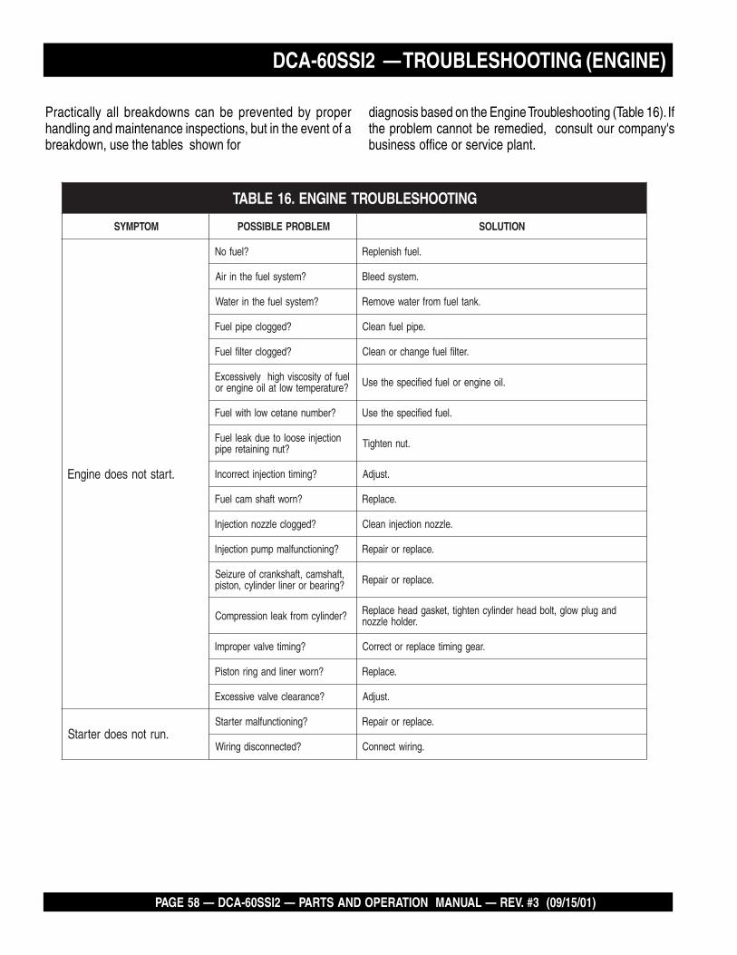
PAGE 58 — DCA-60SSI2 — PARTS AND OPERATION MANUAL — REV. #3 (09/15/01)
DCA-60SSI2 — TROUBLESHOOTING (ENGINE)
Practically all breakdowns can be prevented by properhandling and maintenance inspections, but in the event of abreakdown, use the tables shown for
diagnosis based on the Engine Troubleshooting (Table 16). Ifthe problem cannot be remedied, consult our company'sbusiness office or service plant.
GNITOOHSELBUORTENIGNE.61ELBAT
MOTPMYS MELBORPELBISSOP NOITULOS
.tratstonseodenignE
?leufoN .leufhsinelpeR
?metsysleufehtniriA .metsysdeelB
?metsysleufehtniretaW .knatleufmorfretawevomeR
?deggolcepipleuF .epipleufnaelC
?deggolcretlifleuF .retlifleufegnahcronaelC
leuffoytisocsivhgihylevissecxE?erutarepmetwoltalioenignero .lioenigneroleufdeificepsehtesU
?rebmunenatecwolhtiwleuF .leufdeificepsehtesU
noitcejniesooloteudkaelleuF?tungniniaterepip .tunnethgiT
?gnimitnoitcejnitcerrocnI .tsujdA
?nrowtfahsmacleuF .ecalpeR
?deggolcelzzonnoitcejnI .elzzonnoitcejninaelC
?gninoitcnuflampmupnoitcejnI .ecalperroriapeR
,tfahsmac,tfahsknarcfoeruzieS?gniraebrorenilrednilyc,notsip .ecalperroriapeR
?rednilycmorfkaelnoisserpmoC dnagulpwolg,tlobdaehrednilycnethgit,teksagdaehecalpeR.redlohelzzon
?gnimitevlavreporpmI .raeggnimitecalperrotcerroC
?nrowrenildnagnirnotsiP .ecalpeR
?ecnaraelcevlavevissecxE .tsujdA
.nurtonseodretratS?gninoitcnuflamretratS .ecalperroriapeR
?detcennocsidgniriW .gniriwtcennoC

DCA-60SSI2 — PARTS AND OPERATION MANUAL— REV. #3 (09/15/01) — PAGE 59
DCA-60SSI2 — TROUBLESHOOTING (ENGINE)
)DEUNITNOC(GNITOOHSELBUORTENIGNE.61ELBAT
MOTPMYS MELBORPELBISSOP NOITULOS
.htoomstonsinoituloverenignE
?ytridrodeggolcretlifleuF .egnahcronaelC
?deggolcrenaelcriA .egnahcronaelC
noitcejniesooloteudkaelleuF?tungniniaterepip .tunnethgiT
?gninoitcnuflampmupnoitcejnI .ecalperroriapeR
gninepoelzzontcerrocnI?erusserp .tsujdA
rokcutselzzonnoitcejnI?deggolc .ecalperroriapeR
?deggolcepipwolfrevoleuF .naelC
?gninoitcnuflamronrevoG .riapeR
sagtsuahxeeulbroetihwrehtiE.devresbosi
?lioenigneevissecxE .leveldeificepsehtotecudeR
ronrowrenildnagnirnotsiP?kcuts .ecalperroriapeR
?gnimitnoitcejnitcerrocnI .tsujdA
?noisserpmoctneicifeD .ecnaraelcpottsujdA
tsuahxeyargkradrokcalbrehtiE.devresbosisag
?daolrevO .daolehtnesseL
?desuleufedargwoL .leufdeificepsehtesU
?deggolcretlifleuF .egnahcronaelC
?deggolcrenaelcriA .egnahcronaelC
?noitcejnielzzontneicifeD .elzzonehtecalperroriapeR
.tuptuotneicifeD
?gnimitnoitcejnitcerrocnI .tsujdA
otmeesstrapgnivoms'enignE?gnizieseb .ecalperroriapeR
?noitcejnileufnevenU .pmupnoitcejniehtecalperroriapeR
?noitcejnielzzontneicifeD .elzzonehtecalperroriapeR
?kaelnoisserpmoC dnagulpwolg,tlobdaehrednilycnethgit,teksagdaehecalpeR.redlohelzzon
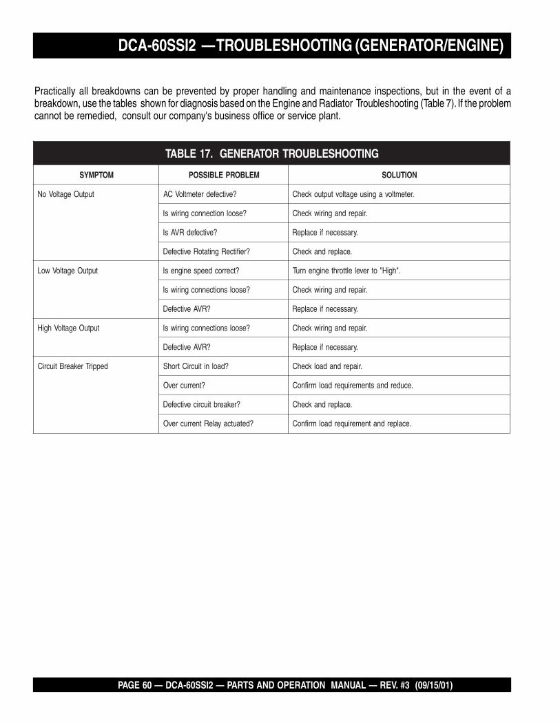
PAGE 60 — DCA-60SSI2 — PARTS AND OPERATION MANUAL — REV. #3 (09/15/01)
GNITOOHSELBUORTROTARENEG.71ELBAT
MOTPMYS MELBORPELBISSOP NOITULOS
tuptuOegatloVoN ?evitcefedretemtloVCA .retemtlovagnisuegatlovtuptuokcehC
?esoolnoitcennocgniriwsI .riaperdnagniriwkcehC
?evitcefedRVAsI .yrassecenfiecalpeR
?reifitceRgnitatoRevitcefeD .ecalperdnakcehC
tuptuOegatloVwoL ?tcerrocdeepsenignesI ."hgiH"otrevelelttorhtenignenruT
?esoolsnoitcennocgniriwsI .riaperdnagniriwkcehC
?RVAevitcefeD .yrassecenfiecalpeR
tuptuOegatloVhgiH ?esoolsnoitcennocgniriwsI .riaperdnagniriwkcehC
?RVAevitcefeD .yrassecenfiecalpeR
deppirTrekaerBtiucriC ?daolnitiucriCtrohS .riaperdnadaolkcehC
?tnerrucrevO .ecuderdnastnemeriuqerdaolmrifnoC
?rekaerbtiucricevitcefeD .ecalperdnakcehC
?detautcayaleRtnerrucrevO .ecalperdnatnemeriuqerdaolmrifnoC
Practically all breakdowns can be prevented by proper handling and maintenance inspections, but in the event of abreakdown, use the tables shown for diagnosis based on the Engine and Radiator Troubleshooting (Table 7). If the problemcannot be remedied, consult our company's business office or service plant.
DCA-60SSI2 — TROUBLESHOOTING (GENERATOR/ENGINE)

DCA-60SSI2 — PARTS AND OPERATION MANUAL— REV. #3 (09/15/01) — PAGE 61
NOTE PAGE

PAGE 62 — DCA-60SSI2 — PARTS AND OPERATION MANUAL — REV. #3 (09/15/01)
How to read the marks and remarks used in this partsbook.
Items Found In the “Remarks” Column
Serial Numbers-Where indicated, this indicates a serialnumber range (inclusive) where a particular part is used.
Model Number-Where indicated, this shows that thecorresponding part is utilized only with this specific modelnumber or model number variant.
Items Found In the “Items Number” Column
All parts with same symbol in the number column, *, #,+, or %, belong to the same assembly or kit.
Note: If more than one of the same reference number islisted, the last one listed indicates newest (or latest)part available.
EXPLANATION OF CODE IN REMARKS COLUMN

DCA-60SSI2 — PARTS AND OPERATION MANUAL— REV. #3 (09/15/01) — PAGE 63
DCA-60SSI2 DCA-60SSI2 DCA-60SSI2 DCA-60SSI2 DCA-60SSI2 W/ISUZU 6BG1 DIESEL ENGINEW/ISUZU 6BG1 DIESEL ENGINEW/ISUZU 6BG1 DIESEL ENGINEW/ISUZU 6BG1 DIESEL ENGINEW/ISUZU 6BG1 DIESEL ENGINE 1 1 1 1 1 TTTTTO 3 UNITSO 3 UNITSO 3 UNITSO 3 UNITSO 3 UNITS
DCA-60SSI2 — SUGGESTED SPARE PARTS
NOTEPart number on this Suggested SpareParts list may supercede/replace theP/N shown in the text pages of this
book.
Qty. P/N Description1 ......... 0601805869 ......... CIRCUIT BREAKER1 ......... 0601820671 ......... AUTOMATIC VOLTAGE REGULATOR1 ......... 0601840073 ......... RHEOSTAT VOLTAGE REGULATOR1 ......... 0601840121 ......... KNOB REHOSTAT1 ......... 0602013901 ......... RADIATOR HOSE, UPPER1 ......... 0602013160 ......... RADIATOR HOSE, LOWER5 ......... 1878100753 ......... OIL FILTER5 ......... X132400240 ........ FUEL FILTER5 ......... 0602040193 ......... ELEMENT, AIR1 ......... 0602122200 ......... UNIT OIL PRESSURE1 ......... 0602123204 ......... UNIT WATER PRESSURE1 ......... 0601810244 ......... BULB, ALARM LAMP1 ......... 0601808507 ......... TRANSDUCER WATT METER1 ......... 8972322520 ......... FAN BELT1 ......... 1823100080 ......... STARTER SWITCH3 ......... KEYISUZUF ........ KEY, STARTER SWITCH

PAGE 64 — DCA-60SSI2 — PARTS AND OPERATION MANUAL — REV. #3 (09/15/01)
DCA-60SSI2 --- GENERATOR ASSY.GENERATOR ASSY.

DCA-60SSI2 — PARTS AND OPERATION MANUAL— REV. #3 (09/15/01) — PAGE 65
NO. PART NO. ITEM QTY. REMARKS
DCA-60SSI2 --- GENERATOR ASSY.
GENERATOR ASSY.
1 8081000302 ROTOR ASSY. ................................ 1 ........... UP TO S/N36211721 8081000312 ROTOR ASSY. ................................ 1 ........... FROM S/N3621173~1-1 FIELD ASSY. 11-2 8051070003 FAN 11-3 0010310030 HEX. HEAD BOLT ........................... 8 ........... UP TO S/N3621172
0012110035 HEX. HEAD BOLT ........................... 8 ........... S/N3621173~1-4 030210250 LOCK WASHER .............................. 8 ........... REPLACES 00425100001-5 8041611004 COUPLING DISK 41-6 8041015003 BALANCING PLATE 11-7 0010310025 HEX. HEAD BOLT ........................... 6 ........... REPLACES 00103100251-8 0042610000 LOCK WASHER 61-6 8001026013 SET PLATE RECTUFER 11-10 0601821349 RECTIFIER ..................................... 2 ............ PT36101-11 0601822601 SURGER ABSORBER .................... 1 ............ ERZM14JK621A1-12 8001020004 INSULATOR WASHER 11-13 8001020504 INSULATOR WASHER 11-14 0010108020 LOCK WASHER 41-15 0040008000 LOCK WASHER 41-16 0601000209 BALANCING WEIGHT KIT 11-17 0070806309 BEARING ........................................ 1 ........... 6309DU;UP TO S/N36211721-17 0071906310 BEARING ........................................ 1 ........... 6310DDU; S/N3621173~2 8051614003 COUPLING RING 13 8051653004 REAMER BOLT 24 012010030 HEX. HEAD BOLT ........................... 7 ........... REPLACES 00121100305 0042510000 LOCK WASHER .............................. 9 ........... REPLACES 00425100006 8081340503 STRATOR ASSY. 17 0845041904 GROMMET 28 8041315202 END BRACKET .............................. 1 ........... UP TO S/N3621728 8041315202 END BRACKET .............................. 1 ........... S/N362173~9 8041350013 FIELD ASSY. EXCITER 110 0010308065 HEX. HEAD BOLT 411 0042608000 LOCK WASHER 412 031108160 PLAIN WASHER ............................. 6 ........... REPLACES 004120800013 0010108025 HEX. HEAD BOLT 614 0040008000 LOCK WASHER 615 0041208000 PLAIN WASHER 616 0601000003 WAVE WASHER .............................. 1 ........... BWW6309; UP TO S/N362117217 8041310014 COVER, BEARING ......................... 1 ........... UP TO S/N3621172
8041310024 COVER, BEARING ......................... 1 ........... S/N3621173~18 8041312004 GASKET, BEARING ....................... 1 ........... UP TO S/N3621173
8041310014 GASKET, BEARING ....................... 1 ........... S/N3621173~

PAGE 66 — DCA-60SSI2 — PARTS AND OPERATION MANUAL — REV. #3 (09/15/01)
DCA-60SSI2 --- GENERATOR ASSY.GENERATOR ASSY.

DCA-60SSI2 — PARTS AND OPERATION MANUAL— REV. #3 (09/15/01) — PAGE 67
19 8041331014 COVER, END BRACKET 120 0105050616 HEX. HEAD BOLT ........................... 8 ........... REPLACES 001710601221 8001333003 COVER, END BRACKET 122 0010106030 HEX. HEAD BOLT 223 0040006000 LOCK WASHER 224 952404470 PLAIN WASHER ............................ 2 ........... REPLACES 004120600025 015091025 HEX. HEAD BOLT ........................... 6 ........... REPLACES 001031002526 030210250 LOCK WASHER .............................. 6 ........... REPLACES 004251000027 8051332003 COVER, FAN................................... 1 ........... UP TO S/N3621172
8051332014 COVER, FAN................................... 1 ........... S/N3621173~28 0605000010 RUBBER SUSPENSION29 0030012000 HEX. NUT 4
0040012000 LOCK WASHER 4
NO. PART NO. ITEM QTY. REMARKS
DCA-60SSI2 --- GENERATOR ASSY.
GENERATOR ASSY.

PAGE 68 — DCA-60SSI2 — PARTS AND OPERATION MANUAL — REV. #3 (09/15/01)
DCA-60SSI2 --- CONTROL BOX ASSY.
CONTROL BOX ASSY.

DCA-60SSI2 — PARTS AND OPERATION MANUAL— REV. #3 (09/15/01) — PAGE 69
NO. PART NO. ITEM QTY. REMARKS
DCA-60SSI2 --- CONTROL BOX ASSY.
CONTROL BOX ASSY.
1 8081812502 CONTROL BOX ............................................ 1 ....... UP TO S/N3646800B4214000002 CONTROL BOX ............................................ 1 ....... S/N3646801~
2 0601801143 CURRENT TRANSFORMER, AMMETER ..... 3 ....... CT-3.5MR 100/5A3 0027104010 MACHINE SCREW 64 0601823860 RELAY UNIT ................................................. 2 ....... MSA90135 0027104016 MACHINE SCREW 46 0601820628 AUTOMATIC VOLTAGE REGULATOR ........... 1 ....... NTA5A2D; UP TO S/N3656070
0601820671 AUTOMATIC VOLTAGE REGULATOR ........... 1 ....... NTA5A2DB; S/N3656071~7 0027105012 MACHINE SCREW 48 0601820853 OVER CURRENT RELAY ............................. 1 ....... THK20KP; UP TO S/N3656070
0601820892 OVER CURRENT RELAY ............................. 1 ....... THN20HZKP; S/N3656071~9 0027104016 MACHINE SCREW 410 0602200405 EMERGENCY RELAY .................................. 1 ....... ISUZU 182550073011 0027106016 MACHINE SCREW 412 0601823706 RELAY .......................................................... 1 ....... HE1AAHE1112 DC24V13 0027104016 MACHINE SCREW 214 0601805352 CIRCUIT BREAKER ..................................... 1 ....... KM203150AT; UP TO S/N364680014 0601805869 CIRCUIT BREAKER ..................................... 1 ....... NY203A 150AT; S/N3646801~15 0021004020 MACHINE SCREW 4
0040004000 LOCK WASHER 4031104080 PLAIN WASHER ........................................... 4 ....... REPLACES 0041204000
16 M1923100004 SELECTOR SWITCH .................................... 1 ....... REPLACES 801015310417 0020004010 MACHINE SCREW ....................................... 4 ....... REPLACES 002110401018 8051839504 BRACKET, SELECTOR SWITCH 119 0021003010 MACHINE SCREW 420 0017106016 HEX. HEAD BOLT 2
020106050 HEX. NUT ..................................................... 2 ....... REPLACES 003000600021 7451822503 CONTROL PANEL ......................................... 1 ....... UP TO /SN3646800
7451822513 CONTROL PANEL ......................................... 1 ....... S/N36463801~22 0601800460 FREQUENCY METER .................................. 1 ....... PAK60 220V 45~65Hz23 0601800784 AC AMMETER .............................................. 1 ....... PSK60 0~100A -~200A24 0601801040 CHANGE-OVER SWITCH, AMMETER ......... 1 ....... SL2AS25 0601800212 AC VOLTMETER ........................................... 1 ....... REPLACES 0601800217 PCK60 0~600V26 0601801041 CHANGE-OVER SWITCH, VOLTMETER ...... 1 ....... SL2VS27 0601810072 PILOT LAMP ................................................. 1 ....... LP132DC 220V
0601810261 BULB............................................................. 1 ....... T1328 0601840073 VOLTAGE REGULATOR ................................ 1 ....... RA20A2SE102BJ 2W 1k OHM29 0601840121 KNOB 1

PAGE 70 — DCA-60SSI2 — PARTS AND OPERATION MANUAL — REV. #3 (09/15/01)
DCA-60SSI2 --- CONTROL BOX ASSY.
CONTROL BOX ASSY.

DCA-60SSI2 — PARTS AND OPERATION MANUAL— REV. #3 (09/15/01) — PAGE 71
NO. PART NO. ITEM QTY. REMARKS
DCA-60SSI2 --- CONTROL BOX ASSY.
CONTROL BOX ASSY.
30 3331824003 STOPPER, CONTROL PANEL 131 0027105016 MACHINE SCREW 2
0030005000 HEX. NUT 232 0805001304 SET SCREW................................................. 2 ....... UP TO S/N3655377
0845056404 SET SCREW................................................. 2 ....... S/N3655378~33 031108160 PLAIN WASHER ........................................... 2 ....... REPLACES 004120800034 020108060 HEX. NUT ..................................................... 2 ....... REPLACES 003000800035 0027105010 MACHINE SCREW 436 8081814503 COVER 137 0017106016 HEX. HEAD BOLT 1138 8081814604 SIDE PANEL 139 0017106016 HEX. HEAD BOLT 440 011208025 HEX. HEAD BOLT ......................................... 4 ....... REPLACES 0017108025

PAGE 72 — DCA-60SSI2 — PARTS AND OPERATION MANUAL — REV. #3 (09/15/01)
DCA-60SSI2 ENGINE AND RADIATOR ASSY.
ENGINE AND RADIATOR ASSY.

DCA-60SSI2 — PARTS AND OPERATION MANUAL— REV. #3 (09/15/01) — PAGE 73
DCA-60SSI2 ENGINE AND RADIATOR ASSY.
NO. PART NO. ITEM QTY. REMARKSENGINE AND RADIATOR ASSY.
1 0602000100 ENGINE ........................................... 1 ......... ISUZU 6BD1; UP TO S/N3656070B4924200114 ENGINE ........................................... 1 ......... ISUZU A6BD1; S/N3656071~
2 0602010802 RADIATOR ....................................... 1 ......... H1901100003 0017108020 HEX. HEAD BOLT 64 0602013901 RADIATOR HOSE ............................ 1 ......... B4000085 0602013160 RADIATOR HOSE ............................ 1 ......... B4000076 0602014302 HOSE BAND 37 06020143303 HOSE BAND 18 0602040090 AIR CLEANER ................................. 1 ......... FWG088006
0602040193 ELEMENT, AIR CLEANER............... 1 ......... P1049729 0602040690 DUST INDICATOR ............................ 1 ......... RBX00225210 0602040598 BAND, AIR CLEANER ..................... 2 ......... AAH00826311 0017108020 HEX. HEAD BOLT 412 7452032303 HOSE, AIR CLEANER 113 0605515008 HOSE BAND 214 0602041106 ELEMENT, OIL FILTER ................... 1 ......... 187810075115 0602042106 ELEMENT, FUEL FILTER ................ 1 ......... 988511911;UP TO S/N3656070
X132400240 ELEMENT, FUEL FILTER ................ 1 ......... S/N3656071~; REPLACES 113240079116 3345112403 ENGINE FOOT 117 3345112503 ENGINE FOT 118 0010710025 HEX. HEAD BOLT 719 0030610000 HEX. NUT 120 0040010000 LOCK WASHER 821 060500009 RUBBER SUSPENSON 422 0040012000 LOCK WASHER 423 0030112000 HEX. NUT 424 1819001931 ENGINE STEOPPER ...................... 1 ......... REPLACES 0602210803 & 181900016125 7452215104 BRACKET, ENGINE STOPPER 126 0027106016 MACHIEN SCREW 327 00171080220 HEX. HEA BOLT 2

PAGE 74 — DCA-60SSI2 — PARTS AND OPERATION MANUAL — REV. #3 (09/15/01)
DCA-60SSI2 ENGINE AND RADIATOR ASSY.
ENGINE AND RADIATOR ASSY.

DCA-60SSI2 — PARTS AND OPERATION MANUAL— REV. #3 (09/15/01) — PAGE 75
DCA-60SSI2 ENGINE AND RADIATOR ASSY.
ENGINE AND RADIATOR ASSY.
28 74522051104 DRIAN JOINT 129 0805013704 PACKING, OIL PAN SIDE 130 0805014204 PACKING 131 3362054104 JOINT BOLT 132 3362051003 DRIAN GOINT 133 0802024004 PACKING 134 0802010204 PLUG135 7452053104 DRINAG HOSE 136 0605515158 HOSE BAND 237 0017108020 HEX. HEAD BOLT 238 0030008000 HEX. NUT 239 0845031303 RESERVE TANK 140 0802081104 CAP, RESERVE TANK 141 7452082504 BRAKET, RESERVE TANK 142 0017108020 HEX. HEAD BOLT 243 0017106025 HEX. HEAD BOLT 144 0199500470 HOSE 145 0199500175 HOSE 146 0193602000 HOSE 147 0605515013 HOSE BAND 448 0193100950 HOSE 149 0605515007 HOSE BAND 150 0193800850 HOSE 151 0605515019 HOSE BAND 152 7452220404 EARTH CABLE 153 8970209410 FILTER ............................................. 1 ......... REPLACES 9581541441
NO. PART NO. ITEM QTY. REMARKS

PAGE 76 — DCA-60SSI2 — PARTS AND OPERATION MANUAL — REV. #3 (09/15/01)
ENGINE OPERATING PANEL ASSY.
DCA-60SSI2 --- ENGINE OPERATING PANEL ASSY.

DCA-60SSI2 — PARTS AND OPERATION MANUAL— REV. #3 (09/15/01) — PAGE 77
ENGINE OPERATING PANEL ASSY.
DCA-60SSI2 --- ENGINE OPERATING PANEL ASSY.
NO. PART NO. ITEM QTY. REMARKS1 7452111103 OPERATING PANEL 12 7452142014 SLIDE BAR 13 0601840190 KNOB ............................................... 1 ......... REPLACES 08050129044 020108060 HEX. NUT ........................................ 1 ......... REPLACES 00360030005 7452140504 BRACKET, GOVERNOR ROD 16 020108060 HEX. NUT ........................................ 2 ......... REPLACES 00300080007 0605010503 SNAP PIN 18 1823100080 STARTER SWITCH .......................... 1 ......... REPLACES 06021000004
KEYISUZUF KEY, STARTER SWITCH 19 1814020031 PREHEAT LAMP.............................. 1 ......... REPLACES 982530043010 0602120054 TACHOMETER................................. 1 ......... 25000KX411011 0602120154 CABLE, TACHOMETER ................... 1 ......... 621000KA6710L=115012 0602122060 OIL PRESSURE GAUGE ................. 1 ......... 4200KX141013 0602122200 UNIT, OIL PRESSURE..................... 1 ......... 53000AC010114 0131300000 STREET SOCKET ........................... 1 ......... UP TO S/N362345714 9099022380 STREET SOCKET ........................... 1 ......... S/N3623458~; REPLACES 060330635015 0602123061 WATER TEMPERATURE GAUGE .... 1 ......... 51400KA120016 0602123204 UNIT, WATER TEMPERATURE ........ 1 ......... 41400KA120017 0602121052 CHARGING AMMETER GAUGE ..... 1 ......... 43000KV030018 0602103091 ALARM LAMP .................................. 2 ......... REPLACES 0602103090
0601810244 BULB 219 0601830420 SWITCH, LAMP CHECK.................. 1 ......... SB61A20 0601810120 PANEL LIGHT .................................. 1 ......... DL31000
0601810214 BULB................................................ 1 ......... REPLACES 060181020121 0040520000 TOOTHED LOCK WASHER 122 0601830710 SWITCH, PANEL LIGHT .................. 1 ......... S301T23 011008040 HEX. HEAD BOLT ............................ 2 ......... REPLACES 0010008040
0040008000 LOCK WASHER 2031108160 PLAIN WASHER ............................... 2 ......... REPLACES 0041208000
24 011008020 HEX. HEAD BOLT ............................. 2 ......... REPLACES 001710802025 8085312103 SUPPORT LEG 126 0017110025 HEX.HEAD BOLT 227 011208025 HEX. HEAD BOLT ............................ 2 ......... REPLACES 0017108025
020108060 HEX. NUT ........................................ 2 ......... REPLACES 003000800028 7452183004 LINK, GOVERNOR ROD 129 0105091025 HEX. HEAD BOLT ............................ 1 ......... REPLACES 001001002530 031110160 PLAIN WASHER .............................. 2 ......... REPLACES 004121000031 020310080 HEX. NUT ........................................ 1 ......... REPLACES 003001000032 7452182014 GOVERNOR ROD 133 7452152004 GOVERNOR ROD 134 0602180106 BALL JOINT 235 020108060 HEX. NUT ........................................ 2 ......... REPLACES 0030008000

PAGE 78 — DCA-60SSI2 — PARTS AND OPERATION MANUAL — REV. #3 (09/15/01)
ENGINE OPERATING PANEL ASSY.
DCA-60SSI2 --- ENGINE OPERATING PANEL ASSY.

DCA-60SSI2 — PARTS AND OPERATION MANUAL— REV. #3 (09/15/01) — PAGE 79
36 0602180108 BALL JOINT 137 020106050 HEX. NUT ........................................ 3 ......... REPLACES 003000600038 952404470 PLAIN WASHER .............................. 1 ......... REPLACES 004120600039 8111860103 SET BOARD, OUPUT TERMINAL 140 0801830204 OUTPUT TERMINAL 541 0801830704 HEX. HEAD BOLT 542 0039312000 HEX. NUT 1043 0040012000 LOCK WASHER 1544 0041412000 PLAIN WASHER 2045 011208030 HEX. HEAD BOLT ............................ 5 ......... REPLACES 001710803046 8081865504 COVER, OUTPUT TERMINAL 147 0605010051 HINGE 248 0027103016 MACHINE SCREW 12
0207003000 HEX. NUT 649 0017106016 HEX. HEAD BOLT 250 0601811034 RECEPTACLE .................................. 2 ......... REPLACES 0601812565; CS6369 250V 50A;51 0601811030 RECEPTACLE .................................. 2 ......... UP TO S/N3627236; 5-20R 125V0 20A
0601812598 RECEPTACLE .................................. 1 ......... S/N3627237~;GF53 OEM 125V 20A52 0027103010 MACHINE SCREW 10
0207003000 HEX. NUT ...................................... 10 ......... REPLACES 0030003000S8413 PLAIN WASHER ............................ 10 ......... REPLACES 0041203000
53 0601805306 CIRCUIT BREAKER ........................ 2 ......... UP TO S/N3627236; KM51 265V 40A0601804887 CIRCUIT BREAKER ........................ 2 ......... S/N3627237~;REPLACES 0601805313
KM51 265V 20A54 0601805840 CIRCUIT BREAKER ........................ 3 ......... KM52 265V 50A55 8081816303 BRACKET, CIRCUIT BREAKER 1
0222100200 RUBBER SHEET 156 0017106016 HEX. HEAD BOLT 257 8085182004 RUBBER COVER 159 011206020 HEX. HEAD BOLT ............................ 6 ......... REPLACES 001710602060 8081865303 COVER, RECEPTACLE 161 12212045 HEX. HEAD BOLT ............................ 2 ......... REPLACES 001001204562 031112230 PLAIN WASHER .............................. 4 ......... REPLACES 004161200063 0805009804 RUBBER WASHER 264 0030012000 HEX. NUT 265 0601820015 RECTIFER ....................................... 4 ......... IS276266 0601802133 FUSE ............................................... 1 ......... 5A67 0601851780 GROMMET ...................................... 2 ......... S/N3700638~
ENGINE OPERATING PANEL ASSY.
DCA-60SSI2 --- ENGINE OPERATING PANEL ASSY.
NO. PART NO. ITEM QTY. REMARKS

PAGE 80 — DCA-60SSI2 — PARTS AND OPERATION MANUAL — REV. #3 (09/15/01)
DCA-60SSI2 --- BATTERY ASSY.
BATTERY ASSY.

DCA-60SSI2 — PARTS AND OPERATION MANUAL— REV. #3 (09/15/01) — PAGE 81
NO. PART NO. ITEM QTY. REMARKS
DCA-60SSI2 --- BATTERY ASSY.
BATTERY ASSY.
1 0168409541 BATTERY ......................................... 2 ......... 95E41R2 0805003904 BATTERY SHEET 23 0805004004 BATTERY BAND 24 0805002904 BATTERY BOLT 45 031108160 PLAIN WASHER .............................. 4 ......... REPLACES 00412080006 0040008000 LOCK WASHER 47 0037808000 WING NUT 48 0215260065 BATTERY CABLE 19 0211160180 BATTERY CABLE 110 0215860100 BATTERY CABLE 111 0602220310 TERMINAL ASSY (+) 2
020800800 WING NUT 212 0602220311 TERMINAL ASSY (-) 2
0208008000 WING NUT 213 0845040414 TERMINAL CAP 214 0845041304 TERMINAL CAP 2

PAGE 82 — DCA-60SSI2 — PARTS AND OPERATION MANUAL — REV. #3 (09/15/01)
DCA-60SSI2 --- MUFFLER ASSY.
MUFFLER ASSY.

DCA-60SSI2 — PARTS AND OPERATION MANUAL— REV. #3 (09/15/01) — PAGE 83
NO. PART NO. ITEM QTY. REMARKS
DCA-60SSI2 --- MUFFLER ASSY.
MUFFLER ASSY.
1 8082330303 EXHAUST PIPE 12 1141450690 GASKET .......................................... 1 ......... REPLACES 92211600103 9091103100 HEX. NUT ........................................ 6 ......... REPLACES 90911031004 3802311122 MUFFLER 15 012210020 HEX. HEAD BOLT ............................ 4 ......... REPLACES 00171100206 7452330303 EXHAUST PIPE 17 B4334200404 GASKET 18 011008035 HEX. HEAD BOLT ............................ 4 ......... REPLACES 00101080359 031108160 PLAIN WASHER .............................. 4 ......... REPLACES 004120800010 0040008000 LOCK WASHER 411 0030008000 HEX. NUT 412 1382320003 PIPE BAND 113 011208030 HEX. HEAD BOLT ............................ 1 ......... REPLACES 001000803014 031108160 PLAIN WASHER .............................. 1 ......... REPLACES 004120800015 020108060 HEX. NUT ........................................ 1 ......... REPLACES 003000800016 3342354104 COVER 117 3342354004 COVER 218 3342328104 PIPE CLAMPER 119 031108160 PLAIN WASHER .............................. 2 ......... REPLACES 004120800020 020108060 HEX. NUT ........................................ 4 ......... REPLACES 003000800021 3342359004 COVER SHEET 222 011208025 HEX. HEAD BOLT ............................ 4 ......... REPLACES 0017108025

PAGE 84 — DCA-60SSI2 — PARTS AND OPERATION MANUAL — REV. #3 (09/15/01)
DCA-60SSI2 --- FUEL TANK ASSY.
FUEL TANK ASSY.

DCA-60SSI2 — PARTS AND OPERATION MANUAL— REV. #3 (09/15/01) — PAGE 85
NO. PART NO. ITEM QTY. REMARKS
DCA-60SSI2 --- FUEL TANK ASSY.
FUEL TANK ASSY.
1 7455510303 FUEL TANK 11-1 0810105004 CAP, FUEL TANK 11-2 0810105400 FUEL FILTER 11-3 0193100255 FUEL GAUGE HOSE 11-4 0605515079 HOSE BAND 22 7455523304 TANK BAND 23 0805003414 PAD, TANK BAND 44 011008020 HEX. HEAD BOLT ............................ 2 ......... REPLACES 00171080205 0207008000 HEX. NUT ........................................ 2 ......... REPLACES 02070080006 020108060 HEX. NUT ........................................ 2 ......... REPLACES 00300080007 0222100200 TANK SHEET 48 0131906000 CAP 19 0191301150 SUCTION HOSE 110 0191300670 RETURN HOSE 111 0605515109 HOSE BAND 412 0845032204 DRAIN JOINT .................................. 1 ......... UP TO S/N3653118
0845047504 DRAIN JOINT .................................. 1 ......... S/N3653119~13 0150000018 O RING 114 0802011104 PLUG 1

PAGE 86 — DCA-60SSI2 — PARTS AND OPERATION MANUAL — REV. #3 (09/15/01)
ENCLOSURE ASSY.
DCA-60SSI2 --- ENCLOSURE ASSY.
5 -BLACK6 -CATERPILLAR YELLOW7 -CATO GOLD8 -RED
THE SERIAL NUMBER MAY BE REQUIRED.
ADD THE FOLLOWING DIGITS AFTER THE PART NUMBER WHEN ORDERING ANY PAINTED PANEL TOINDICATE COLOR OF UNIT:1-ORANGE2-WHITE3 -SPECTRUM GRAY4 -SUNBELT GREEN
UP TO S/N3656070

DCA-60SSI2 — PARTS AND OPERATION MANUAL— REV. #3 (09/15/01) — PAGE 87
NO. PART NO. ITEM QTY. REMARKSENCLOSURE ASSY.
DCA-60SSI2 --- ENCLOSURE ASSY.
1 7455111112 BASE 12 7455116004 FLOOR PANLE 13 0017108020 HEX. HEAD BOLT 124 7455116504 COVER 15 0017108020 HEX.HEAD BOLT 26 7455121012 FRONT FRAME ................................... 1 ............UP TO S/N3656070
7455121022 FRONT FRAME ................................... 1 ............S/N3656071~7455109203 ACOUSTIC SHEET 1
7 0017108020 HEX. HEAD BOLT 68 0800251201 FILLER COVER 19 0027106016 MACHINE SCREW 210 7455125503 COVER, FRONT FRAME 1
7455109304 ACOUSTIC SHET 111 0017108020 HEX. HEAD BOLT 1612 7455125304 COVER, FRONT FRAME 113 00171080220 HEX. HEAD BOLT 1214 3385155104 COVER ................................................. 2 ............UP TO S/N365607015 0017106020 HEX. HEAD BOLT ................................ 8 ............UP TO S/N365607016 7455125104 COVER, FRONT FRAME 1
7455109404 ACOUSTIC SHEET 117 0017108020 HEX. HEAD BOLT 418 7455125704 COVER, FRONT FRAME 1
7455109504 ACOUSTIC SHEET 119 0017108020 HEX. HEAD BOLT 420 7455132013 CENTER FRAME ................................. 1 ............UP TO S/N3656070
B4434300003 CENTER FRAME ................................. 1 ............S/N3656071~21 7455132213 CENTER FRAME ................................. 1 ............UP TO S/N3656070
B4434300103 CENTER FRAME ................................. 1 ............S/N3656071~22 0010114040 HEX. HEAD BOLT ................................ 8 ............UP TO S/N3656070
0030014000 HEX. NUT ............................................. 8 ............UP TO S/N36560700040014000 LOCK WASHER ................................... 8 ............UP TO S/N36560700041214000 PLAIN WASHER ................................... 16 ..........UP TO S/N3656070
22 0010124040 HEX. HEAD BOLT ................................ 8 ............S/N3656071~0030014000 HEX. NUT ............................................. 1 ............S/N3656071~0040014000 LOCK WASHER ................................... 8 ............S/N3656071~0041214000 PLAIN WASHER ................................... 9 ............S/N3656071~
23 0010112030 HEX. HEAD BOLT 100040012000 LOCK WASHER 100041212000 PLAIN WASHER 10
24 7455141122 REAR FRAME ...................................... 1 ............UP TO S/N3656070B4444000102 REAR FRAME ...................................... 1 ............S/N3656071 TO 3700637B4444000112 REAR FRAME ...................................... 1 ............S/N3700638~7455109603 ACOUSTIC SHEET 1
25 0017108020 HEX. HEAD BOLT 426 7455155003 COVER, REAR FRAME ....................... 1 ............UP TO S/N3656070
B4444300203 COVER, REAR FRAME ....................... 1 ............S/N3656071~7455109713 ACOUSTIC SHEET 1

PAGE 88 — DCA-60SSI2 — PARTS AND OPERATION MANUAL — REV. #3 (09/15/01)
ENCLOSURE ASSY.
DCA-60SSI2 --- ENCLOSURE ASSY.
5 -BLACK6 -CATERPILLAR YELLOW7 -CATO GOLD8 -RED
THE SERIAL NUMBER MAY BE REQUIRED.
ADD THE FOLLOWING DIGITS AFTER THE PART NUMBER WHEN ORDERING ANY PAINTED PANEL TOINDICATE COLOR OF UNIT:1-ORANGE2-WHITE3 -SPECTRUM GRAY4 -SUNBELT GREEN
UP TO S/N3656070

DCA-60SSI2 — PARTS AND OPERATION MANUAL— REV. #3 (09/15/01) — PAGE 89
ENCLOSURE ASSY.
DCA-60SSI2 --- ENCLOSURE ASSY.
NO. PART NO. ITEM QTY. REMARKS27 0010108040 HEX. HEAD BOLT 8
0040008000 LOCK WASHER 80041208000 PLAIN WASHER 8
28 7455143113 DOOR, REAR FRAME ......................... 1 ............UP TO S/N3656070B4444200203 DOOR, REAR FRAME ......................... 1 ............S/N3656071 TO 3700637B4444200213 DOOR, REAR FRAME ......................... 1 ............S/N3700638~
29 3805147104 WINDOW PLATE 130 0021006020 MACHINE SCREW 6
0030006000 HEX. NUT 60040006000 LOCK WASHER 60041206000 PLAIN WASHER 6
31 0845028303 HINGE .................................................. 2 ............UP TO S/N36560700845047204 HINGE .................................................. 2 ............S/N656071~
32 0017108025 HEX. HEAD BOLT 433 7455161012 ROOF PANEL 1
7455109803 ACOUSTIC SHEET 134 0017108020 HEX. HEAD BOLT 1635 7455165004 GUIDE PANEL, AIR 2
7455109904 ACOUSTIC SHEET 236 0017108020 HEX. HEAD BOLT 837 8085181202 SPLASHER PANEL .............................. 1 ............UP TO S/N3627236
8085181212 SPLASHER PANEL .............................. 1 ............S/N3627237 TO 37006378085181222 SPLASHER PANEL .............................. 1 ............S/N3700638~
38 0010108055 HEX. HEAD BOLT 60040008000 LOCK WASHER 60041208000 PLAIN WASHER 6
39 7455171413 SIDE DOOR ......................................... 1 ............UP TO S/N3656070B4454000703 SIDE DOOR ......................................... 1 ............S/N3656071 TO 3700637B4454000713 SIDE DOOR ......................................... 1 ............S/N3700638~7455105104 ACOUSTIC SHEET ............................. 1 ............UP TO S/N3656070B4494100104 ACOUSTIC SHEET ............................. 1 ............S/N3656071~
40 7455171513 SIDE DOOR ......................................... 1 ............UP TO S/N3656070B4454000803 SIDE DOOR ......................................... 1 ............S/N3656071 TO 3700637B4454000813 SIDE DOOR ......................................... 1 ............S/N3700638~7455105204 ACOUSTIC SHEET ............................. 1 ............UP TO S/N3656070B4494100204 ACOUSTIC SHEET ............................. 1 ............S/N3656071~
41 7455171613 SIDE DOOR ......................................... 1 ............UP TO S/N3656070B4454000903 SIDE DOOR ......................................... 1 ............S/N3656071 TO 3700637B4454000913 SIDE DOOR ......................................... 1 ............S/N3700638~7455105304 ACOUSTIC SHEET ............................. 1 ............UP TO S/N3656070B4494300204 ACOUSTIC SHEET ............................. 1 ............S/N3656071~
42 7455171723 SIDE DOOR ......................................... 1 ............UP TO S/N3656070B4454001003 SIDE DOOR ......................................... 1 ............S/N3656071 TO 3700637B4454001013 SIDE DOOR ......................................... 1 ............S/N3700638~7455105414 ACOUSTIC SHEET ............................. 1 ............UP TO S/N3656070B4494300304 ACOUSTIC SHEET ............................. 1 ............S/N3656071~

PAGE 90 — DCA-60SSI2 — PARTS AND OPERATION MANUAL — REV. #3 (09/15/01)
ENCLOSURE ASSY.
DCA-60SSI2 --- ENCLOSURE ASSY.
UP TO S/N3656070

DCA-60SSI2 — PARTS AND OPERATION MANUAL— REV. #3 (09/15/01) — PAGE 91
ENCLOSURE ASSY.
DCA-60SSI2 --- ENCLOSURE ASSY.
NO. PART NO. ITEM QTY. REMARKS43 0845028203 HINGE .................................................. 4 ............UP TO S/N3656070
0845046904 HINGE .................................................. 4 ............S/N3656071~44 0845028304 HINGE .................................................. 4 ............UP TO S/N3656070
0845047004 HINGE .................................................. 4 ............S/N3656071~45 0017108025 HEX. HEAD BOLT 16
0601850097 RUBBER CUSHION 847 0845031504 CAP 1048 6360510003 EMBLEM............................................... 2 ............UP TO S/N3660480
0600500090 EMBLEM............................................... 2 ............S/N3660481~49 0021106020 MACHINE SCREW 469 0825007362 DOOR HANDLE................................... 5 ............S/N3656071~70 0221806015 MACHINE SCREW .............................. 20 ..........S/N3656071~71 B4444800004 DUCT ................................................... 1 ............S/N3656071~
7455109713 ACOUSTIC SHEET 172 B4444800104 DUCT ................................................... 1 ............S/N3656071~
7455109713 ACOUSTIC SHEET 173 0207006000 HEX. NUT ............................................. 10 ..........S/N3656071~
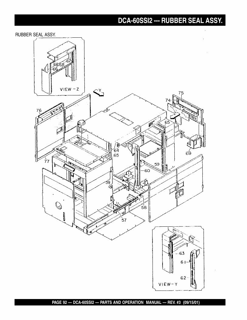
PAGE 92 — DCA-60SSI2 — PARTS AND OPERATION MANUAL — REV. #3 (09/15/01)
DCA-60SSI2 --- RUBBER SEAL ASSY.
RUBBER SEAL ASSY.

DCA-60SSI2 — PARTS AND OPERATION MANUAL— REV. #3 (09/15/01) — PAGE 93
NO. PART NO. ITEM QTY. REMARKS
DCA-60SSI2 --- RUBBER SEAL ASSY.
RUBBER SEAL ASSY. UP TO S/N3656070
57 7455104104 RUBBER SEAL 258 7455104204 RUBBER SEAL 259 7455104304 RUBBER SEAL 360 7455104404 RUBBER SEAL 161 7455104514 RUBBER SEAL 162 7455104614 RUBBER SEAL 163 7455104714 RUBBER SEAL 164 7455104804 RUBBER SEAL 265 7455104904 RUBBER SEAL 266 0225100365 RUBBER SEAL 167 0220100365 RUBBER SEAL 168 0220200750 RUBBER SEAL 2
57 0229200668 RUBBER SEAL 258 0228900665 RUBBER SEAL 159 0228900890 RUBBER SEAL 360 0228900890 RUBBER SEAL 161 0228900555 RUBBER SEAL 162 0228800335 RUBBER SEAL 163 0228900555 RUBBER SEAL 164 0228901465 RUBBER SEAL 165 0229200900 RUBBER SEAL 266 0228800365 RUBBER SEAL 167 0228800325 RUBBER SEAL 168 0228800780 RUBBER SEAL 274 0278100120 RUBBER SEAL .................................... 2 ............SN3700638~75 0228100560 RUBBER SEAL .................................... 1 ............S/N3700638~76 0228900670 RUBBER SEAL .................................... 2 ............S/N3700638~
NO. PART NO. ITEM QTY. REMARKSRUBBER SEAL ASSY. S/N3656071~

PAGE 94 — DCA-60SSI2 — PARTS AND OPERATION MANUAL — REV. #3 (09/15/01)
DCA-60SSI2 --- DECALS
DECAL ASSY.
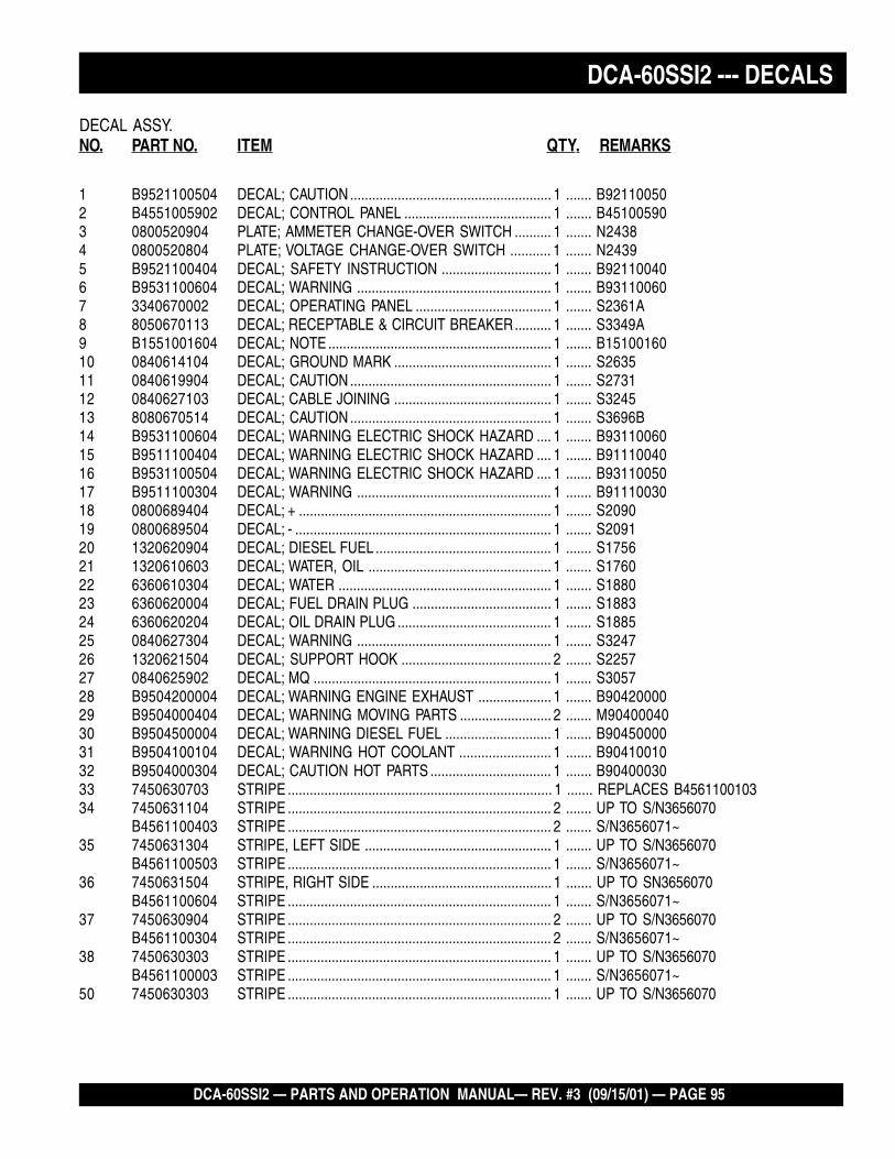
DCA-60SSI2 — PARTS AND OPERATION MANUAL— REV. #3 (09/15/01) — PAGE 95
NO. PART NO. ITEM QTY. REMARKS
DCA-60SSI2 --- DECALS
DECAL ASSY.
1 B9521100504 DECAL; CAUTION ....................................................... 1 ....... B921100502 B4551005902 DECAL; CONTROL PANEL ........................................ 1 ....... B451005903 0800520904 PLATE; AMMETER CHANGE-OVER SWITCH .......... 1 ....... N24384 0800520804 PLATE; VOLTAGE CHANGE-OVER SWITCH ........... 1 ....... N24395 B9521100404 DECAL; SAFETY INSTRUCTION .............................. 1 ....... B921100406 B9531100604 DECAL; WARNING ..................................................... 1 ....... B931100607 3340670002 DECAL; OPERATING PANEL ..................................... 1 ....... S2361A8 8050670113 DECAL; RECEPTABLE & CIRCUIT BREAKER.......... 1 ....... S3349A9 B1551001604 DECAL; NOTE ............................................................. 1 ....... B1510016010 0840614104 DECAL; GROUND MARK ........................................... 1 ....... S263511 0840619904 DECAL; CAUTION ....................................................... 1 ....... S273112 0840627103 DECAL; CABLE JOINING ........................................... 1 ....... S324513 8080670514 DECAL; CAUTION ....................................................... 1 ....... S3696B14 B9531100604 DECAL; WARNING ELECTRIC SHOCK HAZARD .... 1 ....... B9311006015 B9511100404 DECAL; WARNING ELECTRIC SHOCK HAZARD .... 1 ....... B9111004016 B9531100504 DECAL; WARNING ELECTRIC SHOCK HAZARD .... 1 ....... B9311005017 B9511100304 DECAL; WARNING ..................................................... 1 ....... B9111003018 0800689404 DECAL; + ..................................................................... 1 ....... S209019 0800689504 DECAL; - ...................................................................... 1 ....... S209120 1320620904 DECAL; DIESEL FUEL ................................................ 1 ....... S175621 1320610603 DECAL; WATER, OIL .................................................. 1 ....... S176022 6360610304 DECAL; WATER .......................................................... 1 ....... S188023 6360620004 DECAL; FUEL DRAIN PLUG ...................................... 1 ....... S188324 6360620204 DECAL; OIL DRAIN PLUG .......................................... 1 ....... S188525 0840627304 DECAL; WARNING ..................................................... 1 ....... S324726 1320621504 DECAL; SUPPORT HOOK ......................................... 2 ....... S225727 0840625902 DECAL; MQ ................................................................. 1 ....... S305728 B9504200004 DECAL; WARNING ENGINE EXHAUST .................... 1 ....... B9042000029 B9504000404 DECAL; WARNING MOVING PARTS ......................... 2 ....... M9040004030 B9504500004 DECAL; WARNING DIESEL FUEL ............................. 1 ....... B9045000031 B9504100104 DECAL; WARNING HOT COOLANT ......................... 1 ....... B9041001032 B9504000304 DECAL; CAUTION HOT PARTS ................................. 1 ....... B9040003033 7450630703 STRIPE ........................................................................ 1 ....... REPLACES B456110010334 7450631104 STRIPE ........................................................................ 2 ....... UP TO S/N3656070
B4561100403 STRIPE ........................................................................ 2 ....... S/N3656071~35 7450631304 STRIPE, LEFT SIDE ................................................... 1 ....... UP TO S/N3656070
B4561100503 STRIPE ........................................................................ 1 ....... S/N3656071~36 7450631504 STRIPE, RIGHT SIDE ................................................. 1 ....... UP TO SN3656070
B4561100604 STRIPE ........................................................................ 1 ....... S/N3656071~37 7450630904 STRIPE ........................................................................ 2 ....... UP TO S/N3656070
B4561100304 STRIPE ........................................................................ 2 ....... S/N3656071~38 7450630303 STRIPE ........................................................................ 1 ....... UP TO S/N3656070
B4561100003 STRIPE ........................................................................ 1 ....... S/N3656071~50 7450630303 STRIPE ........................................................................ 1 ....... UP TO S/N3656070

PAGE 96 — DCA-60SSI2 — PARTS AND OPERATION MANUAL — REV. #3 (09/15/01)
CYLINDER HEAD COVER ASSY.
ISUZU 6BG1 — CYLINDER HEAD COVER ASSY.

DCA-60SSI2 — PARTS AND OPERATION MANUAL— REV. #3 (09/15/01) — PAGE 97
ISUZU 6BG1 — CYLINDER HEAD COVER ASSY.
EA1013
CYLINDER HEAD COVER ASSY.
NO PART NO PART NAME QTY. REMARKS1 1111803500 CYLINDER HEAD COVER 127 9111790300 GASKET 468 9111791050 CAP NUT WASHER 469 1111730550 GASKET 175 8943401920 NUT 4

PAGE 98 — DCA-60SSI2 — PARTS AND OPERATION MANUAL — REV. #3 (09/15/01)
ISUZU 6BG1 — CYLINDER HEAD ASSY.
CYLINDER HEAD ASSY.

DCA-60SSI2 — PARTS AND OPERATION MANUAL— REV. #3 (09/15/01) — PAGE 99
ISUZU 6BG1 — CYLINDER HEAD ASSY.
CYLINDER HEAD ASSY.
NO PART NO PART NAME QTY. REMARKS1 1111106142 CYLINDER HEAD ASSY. .................. 1 ........ INCL. ITEMS W/*2 1111411960 GASKET 14* 5117210010 VALVE GUIDE 125A* 1117150540 INLET SEAT 65B* 1117110430 EXHAUST SEAT 67A* 1096000051 SEALING CUP, OD=45 17B* 9111291280 SEALING CUP, OD=20 37C* 5112190150 SEALING CUP, OD=32 37D* 5096000130 SEALING CUP, OD=12.3 67E* 1096000160 SEALING CUP, OD=25 57F 9111296010 SEALING CUP, OD=12.5 59 9041108250 STUD, M8X25 L=37 310 1825130430 GLOW PLUG ..................................... 6 ........ REPLACES 982513928911A 5197320011 CONNECTOR, L=236 111B 5197320021 CONNECTOR, L=354 112 9117776221 HANGER 114 9096300260 STUD, M8X86 L=99 1241A 0286810200 BOLT, M10X20 FLANGE 341B 0208014250 BOLT, M14X25 154 9098301630 STUD, M8X83 L=96 456 1093000180 STUD, M8X40 L=58 1281* 9096600340 PLUG, OD=11.9 6112 9099167550 CLIP 1113 0280806100 BOLT, M6X10 FLANGE 1117 9091505140 WASHER 1120A 1090701010 BOLT, M12X113 20120B 1090701000 BOLT, M12X100 6168 5117770551 HANGER 1

PAGE 100 — DCA-60SSI2 — PARTS AND OPERATION MANUAL — REV. #3 (09/15/01)
ISUZU 6BG1 — CYLINDER BLOCK ASSY.
CYLINDER BLOCK ASSY.

DCA-60SSI2 — PARTS AND OPERATION MANUAL— REV. #3 (09/15/01) — PAGE 101
ISUZU 6BG1 — CYLINDER BLOCK ASSY.
CYLINDER BLOCK ASSY.
NO. PART NO. PART NAME QTY. REMARKS1 1112103408 CYLINDER BLOCK 1 .......... INCL. ITEMS W/*2 1878116900 LINER, GRADE=1 ................................................. 6 .......... UP TO DEC. 98; INCL. ITEMS W/#
1878119420 LINER, GRADE=1 ................................................. 6 .......... FROM JAN. 99~1878116910 LINER, GRADE=2 ................................................. 6 .......... UP TO DEC. 981878119430 LINER, GRADE=2 ................................................. 6 .......... FROM JAN. 99~1878116920 LINER, GRADE=3 ................................................. 6 .......... UP TO DEC. 981878119440 LINER, GRADE=3 ................................................. 6 .......... FROM JAN. 99~1878116930 LINER, GRADE=4 ................................................. 6 .......... UP TO DEC. 981878119450 LINER, GRADE=4 ................................................. 6 .......... FROM JAN. 99~
4*# 1112612480 LINER, OD GRD=1 ID GRD=AX ........................... 6 .......... UP TO DEC. 981112613820 LINER, OD GRD=1 ID GRD=AX ........................... 6 .......... FROM JAN. 99~1112612490 LINER, OD GRD=1 ID GRD=CX ........................... 6 .......... UP TO DEC. 981112613830 LINER, OD GRD=1 ID GRD=CX ........................... 6 .......... FROM JAN. 99~1112612500 LINER, OD GRD=2 ID GRD=AX ........................... 6 .......... UP TO DEC. 981112613840 LINER, OD GRD=2 ID GRD=AX ........................... 6 .......... FROM JAN. 99~1112612510 LINER, OD GRD=2 ID GRD=CX ........................... 6 .......... UP TO DEC. 981112613850 LINER, OD GRD=2 ID GRD=CX ........................... 6 .......... FROM JAN. 99~1112612520 LINER, OD GRD=3 ID GRD=AX ........................... 6 .......... UP TO DEC. 981112613860 LINER, OD GRD=3 ID GRD=AX ........................... 6 .......... FROM JAN. 99~1112612530 LINER, OD GRD=3 ID GRD=CX ........................... 6 .......... UP TO DEC. 981112613870 LINER, OD GRD=3 ID GRD=CX ........................... 6 .......... FROM JAN. 99~1112612540 LINER, OD GRD=4 ID GRD=AX ........................... 6 .......... UP TO DEC. 981112613880 LINER, OD GRD=4 ID GRD=AX ........................... 6 .......... FROM JAN. 99~1112612550 LINER, OD GRD=4 ID GRD=CX ........................... 6 .......... UP TO DEC. 981112613890 LINER, OD GRD=4 ID GRD=CX ........................... 6 .......... FROM JAN. 99~
8* 1090004691 BOLT, M16X119 1412 1096660360 CONNECTOR 128 1112191630 COVER 130 8941480790 PIN, OD=16 234 8970233390 VALVE 135 5096230350 GASKET 137 1096050681 PLUG 238 1097400780 PIN, OD=10 L=50 155 1096050660 PLUG, PT 3/8 T=8.0 170* 1096000520 SEALING CUP, OD=60 271 8943673681 GASKET 372C 8970285250 COVER 272D 9112916051 COVER 174 8943675301 BOLT, M8X56 FLANGE 680* 1096000121 CUP, OD=32 382 5093000231 STUD, M14X44 L=65 183 9081510180 PIN, OD=10 L=18 2

PAGE 102 — DCA-60SSI2 — PARTS AND OPERATION MANUAL — REV. #3 (09/15/01)
ISUZU 6BG1 — CYLINDER BLOCK ASSY.
CYLINDER BLOCK ASSY.

DCA-60SSI2 — PARTS AND OPERATION MANUAL— REV. #3 (09/15/01) — PAGE 103
ISUZU 6BG1 — CYLINDER BLOCK ASSY.
NO. PART NO. PART NAME QTY. REMARKSCYLINDER BLOCK ASSY.
113* 5112190140 CUP, OD=28 2130* 5112570011 DOWEL 1136 9112246021 BUSHING 1137 1096800240 DRAIN COCK 1162 9099147010 HOSE, L=900 S.B. L=10000 1179 9095720080 GASKET 6218 9095714120 GASKET ................................................................ 1 .......... UP TO MAR. 98
9095720140 GASKET ................................................................ 1 .......... FROM APR. 98~219 5096540130 NIPPLE 1220 9098600190 PLUG 1236 1093000530 STUD, M10X18.5 L=33 1242 0286808200 BOLT, M8X20 FLANGE 2267 8970157540 CLIP 1269 1096301150 GASKET 1279 0286810200 BOLT, M10X20 FLANGE 2281 5197890030 BRACKET 1335A 5096050180 PLUG, RIGHT SIDE 8335B 1096050791 PLUG, LEFT SIDE 1335C 9992023140 PLUG, LEFT SIDE 1335D 9992023120 PLUG, RIGHT SIDE 1338 5111290030 SEALING CUP, OD=15.6 1

PAGE 104 — DCA-60SSI2 — PARTS AND OPERATION MANUAL — REV. #3 (09/15/01)
ISUZU 6BG1 — OIL PAN AND LEVEL GAUGE ASSY.
OIL PAN AND LEVEL GAUGE ASSY.

DCA-60SSI2 — PARTS AND OPERATION MANUAL— REV. #3 (09/15/01) — PAGE 105
ISUZU 6BG1 — OIL PAN AND LEVEL GAUGE ASSY.
OIL PAN AND LEVEL GAUGE ASSY.
NO. PART NO. PART NAME QTY. REMARKS1 1113604421 OIL PAN ASSY. ............................................... 1 .......... INCL. ITEMS W/*2 1117602000 GAUGE 15* 1096230570 GASKET 16* 9096620120 PLUG 116 1113671000 GASKET 123 0500408180 BOLT, M8X12 W/LOCK WASHER 32119C 9992023240 PLUG, M24X12 1
9992023160 PLUG; M16X12 1120 9095714240 GASKET, ID=24.5 1
9095714160 GASKET, ID=16.5 1151 9112290700 CLIP 1153 9831514320 THERMOMETER 1

PAGE 106 — DCA-60SSI2 — PARTS AND OPERATION MANUAL — REV. #3 (09/15/01)
ISUZU 6BG1 — CAMSHAFT AND VALVE ASSY.
CAMSHAFT AND VALVE ASSY.

DCA-60SSI2 — PARTS AND OPERATION MANUAL— REV. #3 (09/15/01) — PAGE 107
ISUZU 6BG1 — CAMSHAFT AND VALVE ASSY.
CAMSHAFT AND VALVE ASSY.
NO. PART NO. PART NAME QTY. REMARKS1 1125140050 CAMSHAFT 14 1125510830 VALVE, INLET 65 1125520251 VALVE, EXHAUST 67 9920614280 BOLT, M14X28 18 9098518503 WASHER, ID=14.5 19 1125220162 GEAR, Z=50 110 9116810150 THRUST PLATE 111 0500408250 BOLT, M8X25 W/LOCK WASHER 214 9080307130 KEY 137A 9116110480 METAL 137B 9116130350 METAL 551 9091800190 SNAP RING 153 1126210621 ROCKER ARM SHAFT 155 9126260050 PLUG 258 5126280120 BRACKET 165 5126560060 SPLIT COLLAR 2468 1125610990 VALVE SPRING 1271A 8941145790 SPRING SEAT 1271B 5125630010 SPRING SEAT 1272 1125690150 SEAL 1275A 1090005670 BOLT, M8X65 875B 9096021480 BOLT, M8X65 176 9098514300 WASHER 978 1126111180 ROCKER ARM 1281 9126160420 SCREW 1283 9091115080 ADJ. SCREW LOCK NUT 1284 9126281050 BRACKET 688 1125750360 PUSH ROD 1289 5125710032 TAPPET VALVE 1293 1094001160 NUT 494 9095814300 WASHER 495 1095803350 SPRING 5100 5096230600 GASKET 1103 9091505100 WASHER 2107 9125310300 SHAFT 1111 5125350011 COLLAR 1112 8941339373 GEAR 1207 0108110550 BOLT, M10X55 2

PAGE 108 — DCA-60SSI2 — PARTS AND OPERATION MANUAL — REV. #3 (09/15/01)
ISUZU 6BG1 — CRANKSHAFT, PISTON AND FLYWHEEL ASSY.
CRANKSHAFT, PISTON AND FLYWHEEL ASSY.

DCA-60SSI2 — PARTS AND OPERATION MANUAL— REV. #3 (09/15/01) — PAGE 109
ISUZU 6BG1 — CRANKSHAFT, PISTON AND FLYWHEEL ASSY.
CRANKSHAFT, PISTON AND FLYWHEEL ASSY.
NO PART NO PART NAME QTY. REMARKS1 1123104480 CRANKSHAFT ............................ 1 ........ INCL. ITEMS W/*7 1115100742 METAL KIT ................................. 1 ........ INCL. ITEMS W/#12 5123310642 FLYWHEEL 113 9098401071 NUT 114 9098514310 WASHER 115 9123790450 BUSHING 128 8971379101 GEAR, Z=25 131 5097380010 FEATHER KEY 132* 9081512200 PIN 133 5123190032 RING 135 9123336070 GEAR, Z=129 137 1098002140 BEARING 138 5123360081 WASHER 140 9098013340 BOLT 642# 1116800012 WASHER 256 5123712092 PULLEY, 2-GROOVE 163 1121117690 PISTON, STD. GRD=AX 6
1121117700 PISTON, STD. GRD=CX 668 1121211011 RING SET 673 9122716080 METAL SET 683 9122116040 PISTON PIN 684 1122301041 CONNECTOR ARM ASSY. ......... 6 ........ INCL. ITEMS W/%85% 1122510270 BUSHING 686% 1122350271 BOLT, M20X49.5 1293 1123620031 THROWER 196 5123620031 DUST THROWER 1126 8941075751 SNAP RING 12

PAGE 110 — DCA-60SSI2 — PARTS AND OPERATION MANUAL — REV. #3 (09/15/01)
ISUZU 6BG1 — TIMING GEAR AND FLYWHEEL HOUSING ASSY.
TIMING GEAR AND FLYWHEEL HOUSING ASSY.

DCA-60SSI2 — PARTS AND OPERATION MANUAL— REV. #3 (09/15/01) — PAGE 111
ISUZU 6BG1 — TIMING GEAR AND FLYWHEEL HOUSING ASSY.
TIMING GEAR AND FLYWHEEL HOUSING ASSY.
NO. PART NO. PART NAME QTY. REMARKS1 5113110113 TIMING GEAR CASE 12 8943213304 FLYWHEEL HOUSING 132 8943706710 GASKET 135 1096254380 SEAL 136 0280808450 BOLT, M8X45 FLANGE 2
0286808200 BOLT, M8X20 FLANGE 438 9081510180 PIN, OD=10 L=18 149 8970222160 GASKET 154 1113210790 COVER 157 5113210090 TIMING COVER 258 0280806120 BOLT, M6X12 FLANGE 462A 0286808250 BOLT, M8X25 FLANGE 762B 0280808500 BOLT, M8X50 FLANGE 565 8970276011 GASKET 286 9839101012 ELBOW 193 1096234650 GASKET 1175 1096254391 SEAL 1178 8943218380 PLUG 1205 0911602140 NUT 1211 0500408250 BOLT, M8X25 W/LOCK WASHER .. 7 ........... REPLACES 0288914450224 9944112350 STUD, M12X35 L=53 3252 0286808200 BOLT, M8X20 FLANGE 2275 5113270090 POINTER 1297 9095714160 GASKET 1298 9992023160 PLUG 1

PAGE 112 — DCA-60SSI2 — PARTS AND OPERATION MANUAL — REV. #3 (09/15/01)
ISUZU 6BG1 — INLET MANIFOLD ASSY.
INLET MANIFOLD ASSY.

DCA-60SSI2 — PARTS AND OPERATION MANUAL— REV. #3 (09/15/01) — PAGE 113
ISUZU 6BG1 — INLET MANIFOLD ASSY.
INLET MANIFOLD ASSY.
NO. PART NO. PART NAME QTY. REMARKS1 1141121842 INLET MANIFOLD 17 1141150610 GASKET 110A 1141150590 GASKET 110B 1096370610 GASKET 113 0501408280 BOLT, M8X28 ................................. 9 ........... W/LOCK AND PLAIN WASHER20A 9091104080 NUT. M8 320B 0911501080 NUT, M8 FLANGE 322 9091505080 LOCK WASHER 323 9091605080 PLAIN WASHER 327 9040108200 STUD, M8X20 L=36 327A 9040108450 STUD, M8X45 L=61 332 9044110250 STUD, M10X25 L=40 250G 1141123150 PIPE 150I 1141126310 PIPE 154 9091505100 LOCK WASHER 255 9091104100 NUT 294 0500406300 BOLT, M6X30 ................................. 1 ........... W/LOCK WASHER159 8941640270 PIPE 1168 1154192151 CLIP 1225A 9044110280 STUD, M10X28 L=43 2225B 5093000290 STUD, M10X18 L=33 2231 1154192162 STAY 1

PAGE 114 — DCA-60SSI2 — PARTS AND OPERATION MANUAL — REV. #3 (09/15/01)
ISUZU 6BG1 — EXHAUST MANIFOLD ASSY.
EXHAUST MANIFOLD ASSY.

DCA-60SSI2 — PARTS AND OPERATION MANUAL— REV. #3 (09/15/01) — PAGE 115
ISUZU 6BG1 — EXHAUST MANIFOLD ASSY.
EXHAUST MANIFOLD ASSY.
NO. PART NO. PART NAME QTY. REMARKS1A 9141412761 EXHAUST MANIFOLD 11B 9141418030 EXHAUST MANIFOLD 12C 1141451140 GASKET ............................................. 6 ............. UP TO MAR. 992A 8944046100 GASKET ............................................. 3 ............. FROM APR. 99~16 9044110300 STUD, M10X30 L=45 318 9098445650 NUT 12155 9141496530 RING 3

PAGE 116 — DCA-60SSI2 — PARTS AND OPERATION MANUAL — REV. #3 (09/15/01)
ISUZU 6BG1 — VENTILATION ASSY.
VENTILATION ASSY.

DCA-60SSI2 — PARTS AND OPERATION MANUAL— REV. #3 (09/15/01) — PAGE 117
ISUZU 6BG1 — VENTILATION ASSY.
VENTILATION ASSY.
NO. PART NO. PART NAME QTY. REMARKS23 1093607520 HOSE, L=240 124 1097070841 CLIP, ID=20 2141 8941101110 DIAPHRAGM ASSY. 1142 1143620020 COVER 1143 9934905100 SCREW, M5X10 PANHEAD 6

PAGE 118 — DCA-60SSI2 — PARTS AND OPERATION MANUAL — REV. #3 (09/15/01)
ISUZU 6BG1 — WATER PUMP AND CORROSION RESISTOR ASSY.
WATER PUMP AND CORROSION RESISTOR ASSY.

DCA-60SSI2 — PARTS AND OPERATION MANUAL— REV. #3 (09/15/01) — PAGE 119
ISUZU 6BG1 — WATER PUMP AND CORROSION RESISTOR ASSY.
WATER PUMP AND CORROSION RESISTOR ASSY.
NO. PART NO. PART NAME QTY. REMARKS1 1136500180 PUMP ASSY ........................ 1 ..................... INCL. ITEMS W/*3 8943706610 GASKET 14* 1878112530 REPAIR KIT .......................... 1 ..................... INCL. ITEMS W/#7 5136410381 PULLEY, 2-GROOVE, D=173 1 ..................... UP TO MAR. 99
1136411870 PULLEY, 2-GROOVE, D=173 1 ..................... FROM APR. 99~8*# 5136390010 THROWER 19A*# 9099521430 SNAP RING 19B* 9091801520 SNAP RING 110A* 5098000510 BEARING 110B* 5098000500 BEARING 111* 5136340020 SPACER 117*# 5136200062 SEAL UNIT 118*# 9136218020 IMPELLER 119*# 9136136130 GASKET 120* 9136128020 COVER 124* 0280810700 BOLT, M10X70 FLANGE 1
0280810500 BOLT, M10X50 20286810350 BOLT, M10X35 1
25* 5136420072 CENTER 128*# 1095030700 WASHER 129*# 1136310740 SHAFT 165* 9030908200 SCREW 366*# 5096250550 SEAL 1117* 1096601192 CONNECTOR 1
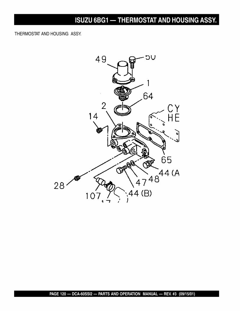
PAGE 120 — DCA-60SSI2 — PARTS AND OPERATION MANUAL — REV. #3 (09/15/01)
THERMOSTAT AND HOUSING ASSY.
ISUZU 6BG1 — THERMOSTAT AND HOUSING ASSY.

DCA-60SSI2 — PARTS AND OPERATION MANUAL— REV. #3 (09/15/01) — PAGE 121
ISUZU 6BG1 — THERMOSTAT AND HOUSING ASSY.
THERMOSTAT AND HOUSING ASSY.
NO. PART NO. PART NAME QTY. REMARKS1 1137700700 THERMOSTAT 12 5137160260 HOUSING 114 9096640050 PLUG, PT 3/4 117 5097040460 CLIP 228 9096620340 HEATER PLUG, M25 144A 0286810350 BOLT, M10X35 344B 0108060950 BOLT, M10X95 347 9091505100 LOCK WASHER 348 9091605100 PLAIN WASHER 349 1137130370 PIPE 150 0501408250 BOLT, M8X25 ............................ 3 ................ W/LOCK AND PLAIN WASHER64 1137430160 GASKET 165 113740130 GASKET 1107 5137210152 PIPE 1

PAGE 122 — DCA-60SSI2 — PARTS AND OPERATION MANUAL — REV. #3 (09/15/01)
ISUZU 6BG1 — ENGINE WATER PIPING ASSY.
ENGINE WATER PIPING ASSY.

DCA-60SSI2 — PARTS AND OPERATION MANUAL— REV. #3 (09/15/01) — PAGE 123
ISUZU 6BG1 — ENGINE WATER PIPING ASSY.
ENGINE WATER PIPING ASSY.
NO. PART NO. PART NAME QTY. REMARKS 132 8971380860 HOSE 1

PAGE 124 — DCA-60SSI2 — PARTS AND OPERATION MANUAL — REV. #3 (09/15/01)
ISUZU 6BG1 — FAN AND FAN BELT ASSY.
FAN AND FAN BELT ASSY.

DCA-60SSI2 — PARTS AND OPERATION MANUAL— REV. #3 (09/15/01) — PAGE 125
ISUZU 6BG1 — FAN AND FAN BELT ASSY.
FAN AND FAN BELT ASSY.
NO. PART NO. PART NAME QTY. REMARKS1 8944838971 FAN, D=550-7 BLOW 116 9091647080 PLAIN WASHER 424 1090440730 BOLT 436 1136712260 BELT, L=1246 2 PIECE SET 138A 8944340750 SPACER, T=51.7 138G 1136420470 SPACER, T=61 168 9091505120 LOCK WASHER 169 9091607120 PLAIN WASHER 270 9991104120 NUT 171 1090091141 BOLT, M10X155 180 1136741181 ADJ. PLATE 181 1136741610 SLIDING PIECE 186 0286810250 ADJ. BOLT, M10X25 FLANGE 1110 9034906100 SCREW, M6X10 2122 9091505080 LOCK WASHER 4

PAGE 126 — DCA-60SSI2 — PARTS AND OPERATION MANUAL — REV. #3 (09/15/01)
ISUZU 6BG1 — FUEL INJECTION ASSY.
FUEL INJECTION ASSY.

DCA-60SSI2 — PARTS AND OPERATION MANUAL— REV. #3 (09/15/01) — PAGE 127
ISUZU 6BG1 — FUEL INJECTION ASSY.
FUEL INJECTION ASSY.
NO. PART NO. PART NAME QTY. REMARKS1 1156032880 FUEL INJ. PUMP ASSY. ........... 1 ................ INCL. ITEMS W/*2 0108108750 BOLT, M8X75 43 9091505080 LOCK WASHER 74A 9098519340 WASHER 44B 9091605080 WASHER 77C 0108108600 BOLT, M8X60 ............................ 7 ................ REPLACES 01080586007D 0500410250 BOLT, M10X25 ........................... 1 ................ W/LOCK WASHER15* 1157801720 COUPLING ASSY. 116 1154151831 PIPE, INJ. NO. 1 117 1154151841 PIPE, INJ. NO. 2 118 1154151851 PIPE, INJ. NO. 3 119 1154151861 PIPE, INJ. NO. 4 120 1154151871 PIPE, INJ. NO. 5 121 1154151881 PIPE, INJ. NO. 6 131 1153002912 NOZZLE ASSY. 632 8970161471 HOLDER ASSY. ........................ 6 ................ INCL. ITEMS W/#33 5153110270 NOZZLE 634# 1096750371 BOLT 635# 1153320170 NUT 636# 1096300820 GASKET, ID=8 OD=13.2 1237# 5153320060 NUT 638# 5153390600 GASKET 639# 8941695030 SCREW 641# 8943203080 CONNECTOR 642# 5153390030 GASKET 644# 5153430050 SPRING 645# 8941695020 PUSH ROD 646# 9153470030 PIN 1254 9153390510 COVER 660 9091505080 LOCK WASHER 1262 9091104080 NUT 1266 5153150030 GASKET 675 9091607100 PLAIN WASHER 378 0500410200 BOLT, M10X20 ........................... 2 ................ W/PLAIN WASHER80 1197511200 BRACKET 185 8943706750 GASKET 1114 9154196120 CLIP 6133 1154124711 PIPE 1134 1096750371 BOLT 1135 1096300820 GASKET, ID=8.2 OD=13.2 2

PAGE 128 — DCA-60SSI2 — PARTS AND OPERATION MANUAL — REV. #3 (09/15/01)
ISUZU 6BG1 — FUEL FILTER AND BRACKET ASSY.
FUEL FILTER AND BRACKET ASSY.

DCA-60SSI2 — PARTS AND OPERATION MANUAL— REV. #3 (09/15/01) — PAGE 129
ISUZU 6BG1 — FUEL FILTER AND BRACKET ASSY.
FUEL FILTER AND BRACKET ASSY.
NO. PART NO. PART NAME QTY. REMARKS1 1132007011 FUEL FILTER ASSY. ................. 1 ................ INiICL. ITEMS W/*21* 1132121080 COVER 129* 1132600470 VALVE 130* 1096300850 GASKET 258* 1132400691 ELEMENT 162 9091104100 NUT 263 9091505100 LOCK WASHER 264 9091605100 PLAIN WASHER 272 9091105100 NUT, M10 299 9091505100 LOCK WASHER 2

PAGE 130 — DCA-60SSI2 — PARTS AND OPERATION MANUAL — REV. #3 (09/15/01)
ISUZU 6BG1 — FUEL PUMP AND PIPE ASSY.
FUEL PUMP AND PIPE ASSY.

DCA-60SSI2 — PARTS AND OPERATION MANUAL— REV. #3 (09/15/01) — PAGE 131
ISUZU 6BG1 — FUEL PUMP AND PIPE ASSY.
FUEL PUMP AND PIPE ASSY.
NO. PART NO. PART NAME QTY. REMARKS107 1154142940 PIPE 1108 1096750860 BOLT 1110 1096300850 GASKET 2111A 5097091030 CLIP, W/TUBE L=48 3111C 5097091040 CLIP, W/OUT TUBE L=45 3112 1096750860 BOLTM14X27 1115 1096300850 GASKET, ID=14.2 OD=19.2 2119 1154142950 PIPE 1123 1154142962 PIPE 1124 1094680021 NUT 1126 0500406300 BOLT M6X30 ............................. 2 ................ W/LOCK WASHER145 9095245550 CLIP, ID=6 1150 1096300850 GASKET, ID=14.2 OD=19.2 2212 1132600011 OVERFLOW VALVE 1216 0500406300 BOLT, M6X30 ............................ 1 ................ W/ LOCK WASHER217 1096300850 GASKET, ID=14.2 OD=19.2 1

PAGE 132 — DCA-60SSI2 — PARTS AND OPERATION MANUAL — REV. #3 (09/15/01)
ISUZU 6BG1 — OIL COOLER AND OIL FILTER ASSY.
OIL COOLER AND OIL FILTER ASSY.

DCA-60SSI2 — PARTS AND OPERATION MANUAL— REV. #3 (09/15/01) — PAGE 133
ISUZU 6BG1 — OIL COOLER AND OIL FILTER ASSY.
OIL COOLER AND OIL FILTER ASSY.
NO. PART NO. PART NAME QTY. REMARKS2 1878100752 OIL FILTER ELEMENT ............. 1 ................ INCL. ITEMS W/%76A 9098009281 BOLTM10X145 276B 0286810350 BOLT, M10X35 2102 1217002491 OIL COOLER ASSY. ................. 1 ................ INCL. ITEMS W/*103A 8942059861 BOLT, M8X65 1103B 0501408450 BOLT, M8X65 .......................... 10 ................ W/LOCK AND PLAIN WASHER103C 0501408280 BOLT. M8X28 ........................... 15 ................ W/LOCK AND PLAIN WASHER103D 1090300910 BOLT, M8X20 ............................ 2 ................ W/PLAIN WASHER107 9091605080 PLAIN WASHER 3110* 1112810281 BODY 1111* 1112820180 CORE 1115* 9091114100 NUT 4116* 9091645100 PLAIN WASHER 4189* 9132630100 PLUG 1190* 9095622150 GASKET 1191* 5095800920 BYPASS SPRING 1192* 5112880010 BYPASS VALVE 1196 5096050170 PLUG 2265# 5132110100 BODY 1281# 5132120212 COVER 1284# 1132310420 BOLT 1288# 109000105 PLUG, M10 1290A%# 9099203110 GASKET 1290B%# 9099206940 GASKET, ID=15.5 1290C%# 1096230550 GASKET, ID=9.8 1292 9099412830 SPRING 1293 9132390250 SEAT 1297 9098621610 PLUG 1307 5132600061 VALVE 1309 1096231630 GASKET 1321 8943706700 GASKET 1328 8941486171 BOLT 1331 9091605100 PLAIN WASHER 2333 9095720100 GASKET, ID=10.2 OD=19 2410 1096231630 GASKET 1444* 1112820140 GASKET 2469 112820200 GASKET 1496 5132000726 OIL FILTER ASSY. .................... 1 ................ INCL. ITEMS W/#

PAGE 134 — DCA-60SSI2 — PARTS AND OPERATION MANUAL — REV. #3 (09/15/01)
ISUZU 6BG1 — OIL PUMP AND OIL STRAINER ASSY.
OIL PUMP AND OIL STRAINER ASSY.

DCA-60SSI2 — PARTS AND OPERATION MANUAL— REV. #3 (09/15/01) — PAGE 135
ISUZU 6BG1 — OIL PUMP AND OIL STRAINER ASSY.
OIL PUMP AND OIL STRAINER ASSY.
NO. PART NO. PART NAME QTY. REMARKS1 1131002770 OIL PUMP ASSY. ...................... 1 ................. INCL. ITEMS W/*2* 5131650040 SEAT 13* 9081140300 PIN 15* 5095800980 SPRING 18* 5131250010 GEAR 111* 1131130470 COVER ASSY. 120* 5131210050 GEAR 129 0286810250 BOLT, M10X25 FLANGE 232* 1131280180 PINION 137* 1131190030 DOWEL 139* 9131190100 COLLAR 140* 1131230160 COUPLING 141* 5098430030 BALL 142* 1131401160 STRAINER 165 9131190100 COLLAR 197* 1090440470 BOLT, M8X60 4

PAGE 136 — DCA-60SSI2 — PARTS AND OPERATION MANUAL — REV. #3 (09/15/01)
ISUZU 6BG1 — OIL AND VACUUM PIPING ASSY.
OIL AND VACUUM PIPING ASSY.

DCA-60SSI2 — PARTS AND OPERATION MANUAL— REV. #3 (09/15/01) — PAGE 137
ISUZU 6BG1 — OIL AND VACUUM PIPING ASSY.
OIL AND VACUUM PIPING ASSY.
NO. PART NO. PART NAME QTY. REMARKS1 5133112050 PIPE ....................................... 1 ................... INCL. ITEMS W/*2 1096750770 BOLT, M10X21 137 5133111190 PIPE 140 0286808400 BOLT, M8X40 FLANGE 447A 9099211880 GASKET, ID=18 247B 1096234620 GASKET, ID=22.8 262 1133115322 PIPE 1110 9098440220 NUT 1117 1096300830 GASKET, ID=10.2 2134* 9099171051 CLIP 1143 0280808400 BOLT, M8X40 FLANGE 4277# 1117500241 CAP 1278 9099129760 HOSE 1279 9099155531 CLIP 2430 9091505080 LOCK WASHER 1434 9091104080 NUT 1448 1117402011 FILLER ................................... 1 ................... INCL. ITEMS W/#

PAGE 138 — DCA-60SSI2 — PARTS AND OPERATION MANUAL — REV. #3 (09/15/01)
ISUZU 6BG1 — ELECTRICAL CONTROL ASSY.
ELECTRICAL CONTROL ASSY.

DCA-60SSI2 — PARTS AND OPERATION MANUAL— REV. #3 (09/15/01) — PAGE 139
ISUZU 6BG1 — ELECTRICAL CONTROL ASSY.
ELECTRICAL CONTROL ASSY.
NO. PART NO. PART NAME QTY. REMARKS1 1811001911 STARTER ASSY. 12 1812003650 GENERATOR ASSY. 17 9991104120 NUT 316 1090001331 BOLT, M14X135 117 9091605140 PLAIN WASHER 118 9091505140 LOCK WASHER 123 9991104140 NUT 126A 0280810250 BOLT, M10X25 FLANGE 126C 0286810350 BOLT, M10X35 238 9825300430 RESISTOR 156A 5831510030 SWITCH ................................... 1 .................. INCL. ITEMS W/*56D* 9827200690 SWITCH 188* 9099022380 ADAPTER 189 8971256010 SWITCH 1252 1197190362 COVER 1292 9091505120 LOCK WASHER 3293 9829322110 CABLE 1488 1819001931 STOPPER 1

PAGE 140 — DCA-60SSI2 — PARTS AND OPERATION MANUAL — REV. #3 (09/15/01)
ISUZU 6BG1 — STARTER COMP. ASSY.
STARTER COMP. ASSY.

DCA-60SSI2 — PARTS AND OPERATION MANUAL— REV. #3 (09/15/01) — PAGE 141
ISUZU 6BG1 — STARTER COMP. ASSY.
STARTER COMP. ASSY.
NO. PART NO. PART NAME QTY. REMARKS1 1811293640 SEAL KIT ........................................ 1 .................. INCL. ITEMS W/12 1811230250 CASE .............................................. 1 .................. INCL. ITEMS W/%3% 1811293970 METAL 14 5811291420 COVER 15 5811291440 CLIP 26 5811291450 STOPPER 18 1811130260 BRACKET 19& 1811293860 BEARING 110 1811230240 SHAFT ........................................... 1 .................. INCL. ITEMS W/&11A 5811291600 WASHER 111B 5811291590 WASHER 211C 5811291580 WASHER 112 1811130730 BRACKET 115 1811160440 WIRE 116 1811210370 ARMATURE ................................... 1 .................. INCL. ITEMS W/#17A# 1811293950 BEARING ....................................... 1 .................. UP TO MAR. 95
5811291550 BEARING ....................................... 1 .................. FROM APR. 95~17B# 1811293850 BEARING ....................................... 1 .................. UP TO MAR. 95
1811291960 BEARING ....................................... 1 .................. FROM APR. 95~18 5811291560 WASHER 219 1811293960 COIL 120* 1811160420 BRUSH, + 221* 1811170140 SPRING 222* 1811180360 HOLDER 123* 1811150620 COVER 127A 1811293870 BOLT 327B 5811292140 BOLT 228 1811270310 LEVER 129 1811291850 PIN 130 5811291470 PLATE 131 5811510360 SWITCH 150* 1811160430 BRUSH, - 254 5811220160 CLUTCH 157 1811150610 COVER ASSY. ................................ 1 .................. INCL. ITEMS W/*59 5811291500 TERMINAL 160 5811291460 PLUNGER 161 5811291480 CONTACT 162 9821161400 BUSHING 163 5811180190 HOLDER 164A 9821161420 WASHER 164B 5811291510 WASHER 265 5811291490 RING 277 1812291140 WASHER 278 1811293840 TERMINAL 180 1811291840 NUT 186 1825530230 RELAY ............................................ 1 .................. UP TO MAR. 95
1825530370 RELAY ............................................ 1 .................. FROM APR. 95~

PAGE 142 — DCA-60SSI2 — PARTS AND OPERATION MANUAL — REV. #3 (09/15/01)
ISUZU 6BG1 — ALTERNATOR COMP. ASSY.
ALTERNATOR COMP. ASSY.

DCA-60SSI2 — PARTS AND OPERATION MANUAL— REV. #3 (09/15/01) — PAGE 143
ISUZU 6BG1 — ALTERNATOR COMP. ASSY.
ALTERNATOR COMP. ASSY.
NO. PART NO. PART NAME QTY. REMARKS1 1812142290 REAR COVER 1 .................. INCL. ITEMS W/#2 1812210720 ROTOR 13T 1812292250 BEARING 13U 8941730540 BEARING 15 1812170620 HOLDER 16# 1812700070 REGULATOR ASSY. 110# 1812170690 RECTIFIER 111# 1812142240 COVER 112 9822158670 KEY 113 1812293830 GASKET 214B 1812295270 COLLAR 114C 1812295430 COLLAR 115H 1812295130 RETAINER 115F 1812293760 RETAINER 115I 1812295260 RETAINER 115L 8941730600 RETAINER 117 1812130670 FRONT COVER 119 1812220550 PULLEY 120 1812230090 FAN 122 1812110900 STATOR 133# 1812295560 WIRE 149# 8941730610 BUSHING 157 1812295440 COVER 162 1812291220 CLIP 169 1812295160 CLIP 1

PAGE 144 — DCA-60SSI2 — PARTS AND OPERATION MANUAL — REV. #3 (09/15/01)
ISUZU 6BG1 — INJ. PUMP COMP. ASSY.
INJ. PUMP COMP. ASSY.

DCA-60SSI2 — PARTS AND OPERATION MANUAL— REV. #3 (09/15/01) — PAGE 145
ISUZU 6BG1 — INJ. PUMP COMP. ASSY.
INJ. PUMP COMP. ASSY.
NO. PART NO. PART NAME QTY. REMARKS1 5156110250 HOUSING ............................................ 1 .................... INCL. ITEMS W/*6* 5156440170 HOLDER 67* 1096230520 GASKET 68* 5156290450 STOPPER 69* 5156430010 SPRING 610* 1156490010 GASKET 614* 5156410010 VALVE 619* 1156310690 PLUNGER ASSY. 633 1096230130 GASKET 146 1156192430 COVER 148 5156191560 GASKET 1449 9812250470 RING 150* 5156210250 CAMSHAFT 151 5196190490 KEY 162 9812350150 SEAT 663 5156430090 SPRING 664 9812350210 SET 668 9812212230 TAPPET ............................................... 6 .................... INCL. ITEMS W/#69# 5156190410 GUIDE 670# 9812222200 PIN 671# 1156290010 BUSHING 672# 1156220030 ROLLER 673*% 1157299600 GASKET 174 1156120500 COVER ................................................ 1 .................... INCL. ITEMS W/%75* 1156190030 SCREW 277 1156190330 BEARING 179* 9812151150 STUD 380 8941711100 NUT 382 5156191360 PLUG 688 1156190920 BOLT 189 1157190930 GASKET 2105 9000906770 BEARING, NSK 1
5098000380 BEARING, NTN 1107 5156290150 SHIM .................................................AR .................... T=0.10
5156290160 SHIM .................................................AR .................... T=0.125156290170 SHIM .................................................AR .................... T=0.145156290180 SHIM .................................................AR .................... T=0.165156290190 SHIM .................................................AR .................... T=0.185156290200 SHIM .................................................AR .................... T=0.505156290380 SHIM .................................................AR .................... T=1.009812250330 SHIM .................................................AR .................... T=0.305156190390 SHIM .................................................AR .................... T=0.705156290900 SHIM .................................................AR .................... T=1.401156390880 SHIM .................................................AR .................... T=2.40
109* 5156370030 RACK 1114 5098000380 BEARING, NTN 1
9000906770 BEARING, NSK 1117 1096300850 GASKET, ID=14.2 OD=19.2 2118 1157590110 BOLT 1126* 9812350170 ADAPTER 1127* 5156190440 ADAPTER 1130 9019006140 SCREW, M6X14 ................................... 4 .................... W/LOCK WASHER148* 9812151440 GASKET 2115 1156190240 BOLT 1

PAGE 146 — DCA-60SSI2 — PARTS AND OPERATION MANUAL — REV. #3 (09/15/01)
ISUZU 6BG1 — INJ. PUMP COMP. ASSY.
INJ. PUMP COMP. ASSY.

DCA-60SSI2 — PARTS AND OPERATION MANUAL— REV. #3 (09/15/01) — PAGE 147
ISUZU 6BG1 — INJ. PUMP COMP. ASSY.
NJ. PUMP COMP. ASSY.
NO. PART NO. PART NAME QTY. REMARKS157* 8941445880 GASKET 1159 9812250470 RING 1160 9884100660 SCREW 2161 9812250430 GASKET 2162 5156290150 SHIM .................................................AR .................... T=0.10
5156290160 SHIM .................................................AR .................... T=0.125156290170 SHIM .................................................AR .................... T=0.145156290180 SHIM .................................................AR .................... T=0.165156290190 SHIM .................................................AR .................... T=0.185156290200 SHIM .................................................AR .................... T=0.505156290380 SHIM .................................................AR .................... T=1.009812250330 SHIM .................................................AR .................... T=0.305156190390 SHIM .................................................AR .................... T=0.705156290900 SHIM .................................................AR .................... T=1.401156390880 SHIM .................................................AR .................... T=2.40
167* 1156390030 BOLT 1176 5156250010 PLATE 3177 9812250570 PINION 6178 9812350030 SCREW 6181 5156190340 SHIM .................................................AR .................... T=0.30
5156190350 SHIM .................................................AR .................... T=0.405156190360 SHIM .................................................AR .................... T=0.505156190010 SHIM .................................................AR .................... T=0.605156190020 SHIM .................................................AR .................... T=0.705156190030 SHIM .................................................AR .................... T=0.805156190040 SHIM .................................................AR .................... T=0.905156190050 SHIM .................................................AR .................... T=1.005156190070 SHIM .................................................AR .................... T=1.105156190080 SHIM .................................................AR .................... T=1.205156190090 SHIM .................................................AR .................... T=1.305156190100 SHIM .................................................AR .................... T=1.405156190110 SHIM .................................................AR .................... T=0.555156190120 SHIM .................................................AR .................... T=0.655156190130 SHIM .................................................AR .................... T=0.755156190150 SHIM .................................................AR .................... T=0.859812350420 SHIM .................................................AR .................... T=0.959812350430 SHIM .................................................AR .................... T=1.059812350440 SHIM .................................................AR .................... T=1.159812350450 SHIM .................................................AR .................... T=1.255156191060 SHIM .................................................AR .................... T=1.505156191070 SHIM .................................................AR .................... T=1.605156190250 SHIM .................................................AR .................... T=0.205156190260 SHIM .................................................AR .................... T=0.255156190270 SHIM .................................................AR .................... T=0.355156190370 SHIM .................................................AR .................... T=0.455156191080 SHIM .................................................AR .................... T=1.355156191090 SHIM .................................................AR .................... T=1.455156191100 SHIM .................................................AR .................... T=1.55

PAGE 148 — DCA-60SSI2 — PARTS AND OPERATION MANUAL — REV. #3 (09/15/01)
ISUZU 6BG1 — GOVERNOR COMP. ASSY.
GOVERNOR COMP. ASSY.
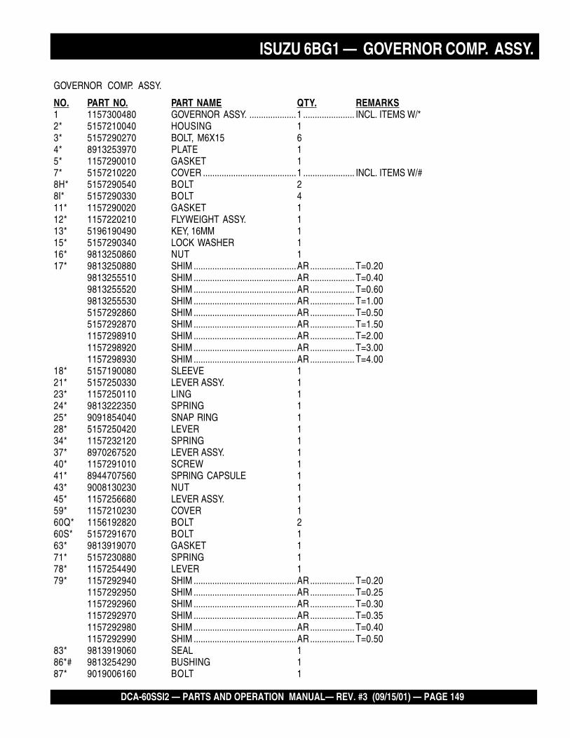
DCA-60SSI2 — PARTS AND OPERATION MANUAL— REV. #3 (09/15/01) — PAGE 149
ISUZU 6BG1 — GOVERNOR COMP. ASSY.
GOVERNOR COMP. ASSY.
NO. PART NO. PART NAME QTY. REMARKS1 1157300480 GOVERNOR ASSY. ....................1 ...................... INCL. ITEMS W/*2* 5157210040 HOUSING 13* 5157290270 BOLT, M6X15 64* 8913253970 PLATE 15* 1157290010 GASKET 17* 5157210220 COVER ........................................1 ...................... INCL. ITEMS W/#8H* 5157290540 BOLT 28I* 5157290330 BOLT 411* 1157290020 GASKET 112* 1157220210 FLYWEIGHT ASSY. 113* 5196190490 KEY, 16MM 115* 5157290340 LOCK WASHER 116* 9813250860 NUT 117* 9813250880 SHIM ............................................AR ................... T=0.20
9813255510 SHIM ............................................AR ................... T=0.409813255520 SHIM ............................................AR ................... T=0.609813255530 SHIM ............................................AR ................... T=1.005157292860 SHIM ............................................AR ................... T=0.505157292870 SHIM ............................................AR ................... T=1.501157298910 SHIM ............................................AR ................... T=2.001157298920 SHIM ............................................AR ................... T=3.001157298930 SHIM ............................................AR ................... T=4.00
18* 5157190080 SLEEVE 121* 5157250330 LEVER ASSY. 123* 1157250110 LING 124* 9813222350 SPRING 125* 9091854040 SNAP RING 128* 5157250420 LEVER 134* 1157232120 SPRING 137* 8970267520 LEVER ASSY. 140* 1157291010 SCREW 141* 8944707560 SPRING CAPSULE 143* 9008130230 NUT 145* 1157256680 LEVER ASSY. 159* 1157210230 COVER 160Q* 1156192820 BOLT 260S* 5157291670 BOLT 163* 9813919070 GASKET 171* 5157230880 SPRING 178* 1157254490 LEVER 179* 1157292940 SHIM ............................................AR ................... T=0.20
1157292950 SHIM ............................................AR ................... T=0.251157292960 SHIM ............................................AR ................... T=0.301157292970 SHIM ............................................AR ................... T=0.351157292980 SHIM ............................................AR ................... T=0.401157292990 SHIM ............................................AR ................... T=0.50
83* 9813919060 SEAL 186*# 9813254290 BUSHING 187* 9019006160 BOLT 1

PAGE 150 — DCA-60SSI2 — PARTS AND OPERATION MANUAL — REV. #3 (09/15/01)
ISUZU 6BG1 — GOVERNOR COMP. ASSY.
GOVERNOR COMP. ASSY.

DCA-60SSI2 — PARTS AND OPERATION MANUAL— REV. #3 (09/15/01) — PAGE 151
ISUZU 6BG1 — GOVERNOR COMP. ASSY.
GOVERNOR COMP. ASSY.
NO. PART NO. PART NAME QTY. REMARKS90* 5157291230 SCREW 1918* 8944278480 SPRING CAPSULE 193S* 9844100270 NUT 193T* 1157790580 NUT 193U* 1157790400 NUT 193V* 1157296890 NUT 194* 1157795020 SCREW 196* 5157290530 PLUG 299* 9813250620 PIN 1101* 8941445880 GASKET 2103* 1157290920 NUT 1104* 8971796700 CAP 1105* 1157259210 LEVER 1106* 9813250300 KEY, 13MM 1107* 9813254880 WASHER AR108* 1157293010 COLLAR 1109* 1157290990 SHIM 1
9813251730 SHIM AR110* 1157290980 SEAL 1111G* 8970242390 BUSHING 1111H* 8970242400 BUSHING 1112* 9813212050 GASKET 2113* 9091854150 RING 2158* 9813252100 CAP 1145* 1157795650 CAP 1150F* 9813150650 ADAPTER 1150G* 1157795670 ADAPTER 1151* 9019008180 BOLT, M8X18 ..............................1 ...................... W/LOCK WASHER154* 1157795620 BOLT 1156* 1835794920 WASHER 1160* 1157290150 GASKET 1161* 1157290380 PLUG 1196* 1157791910 BRACKET 1253* 1157296360 LIMITER 1352* 1157795640 CAP NUT 1429* 5157290990 GASKET 2

PAGE 152 — DCA-60SSI2 — PARTS AND OPERATION MANUAL — REV. #3 (09/15/01)
ISUZU 6BG1 —FEED PUMP ASSY.
FEED PUMP ASSY.

DCA-60SSI2 — PARTS AND OPERATION MANUAL— REV. #3 (09/15/01) — PAGE 153
ISUZU 6BG1 — FEED PUMP ASSY.
FEED PUMP ASSY.
NO. PART NO. PART NAME QTY. REMARKS1 1157501620 PUMP ASSY. .................................. 1 .................. INCL. ITEMS W/*2* 1157610060 PUMP 13* 1196230160 GASKET 14* 9813517020 VALVE SPRING 25* 1157550020 PUMP VALVE 27* 1196230160 GASKET 210* 1157590030 ADAPTER 111* 1096750630 BOLT 112* 1096300850 GASKET 213* 9813550250 SNAP RING 215* 5157510120 HOUSING 116* 9813512050 PISTON 117* 9813513020 SPRING 118* 9813550350 GASKET 119* 8941711850 PLUG 128* 5157540010 TAPPET ASSY. 129* 9813514030 ROLLER 130* 9813514100 PIN 131* 1157590020 GUIDE 2

PAGE 154 — DCA-60SSI2 — PARTS AND OPERATION MANUAL — REV. #3 (09/15/01)
ISUZU 6BG1 — MISC. INJECTION PUMP ASSY.
MISC. INJECTION PUMP ASSY.

DCA-60SSI2 — PARTS AND OPERATION MANUAL— REV. #3 (09/15/01) — PAGE 155
ISUZU 6BG1 — MISC. INJECTION PUMP ASSY.
MISC. INJECTION PUMP ASSY.
NO. PART NO. PART NAME QTY. REMARKS2 1197510490 BRACKET ................................. 1 ................ INCL. ITEM W/*3* 9041010300 STUD 48 9091645100 PLAIN WASHER 49 9091506100 LOCK WASHER 410 5156390020 NUT 4

PAGE 156 — DCA-60SSI2 — PARTS AND OPERATION MANUAL — REV. #3 (09/15/01)
ISUZU 6BG1 — COUPLING ASSY,
COUPLING ASSY.

DCA-60SSI2 — PARTS AND OPERATION MANUAL— REV. #3 (09/15/01) — PAGE 157
ISUZU 6BG1 — COUPLING ASSY.
COUPLING ASSY.
NO. PART NO. PART NAME QTY. REMARKS1 5157810030 COUPLING 12 9096620070 BOLT 13 9884105020 NUT 14 1156192470 PLATE 15 5156190480 WASHER 127 1125240150 GEAR 130 8944575170 BOLT 6

PAGE 158 — DCA-60SSI2 — PARTS AND OPERATION MANUAL — REV. #3 (09/15/01)
ISUZU 6BG1 — WATER SEDIMENTER ASSY.
WATER SEDIMENTER ASSY.

DCA-60SSI2 — PARTS AND OPERATION MANUAL— REV. #3 (09/15/01) — PAGE 159
ISUZU 6BG1 — WATER SEDIMENTER ASSY.
WATER SEDIMENTER ASSY.
NO. PART NO. PART NAME QTY. REMARKS1 1132008410 FUEL SEDIMENTER ................. 1 ................. INCL. ITEMS W/*4* 5132120591 COVER 15* 5096230700 GASKET 17* 5132190200 PLUG 19* 5096300240 GASKET 119 1197550921 BRACKET 120 0280808250 BOLT, M8X25 FLANGE 233*# 8944163770 WASHER 134* 8944537460 PLUG ......................................... 1 ................ INCL. ITEMS W/#36* 5132190221 RING 138* 5132190210 FLOAT 144 5154112231 PIPE 145 1096750860 BOLT, M14X27 246 1096300850 GASKET 447 1154143741 PIPE 156* 1132112110 CASE 1

PAGE 160 — DCA-60SSI2 — PARTS AND OPERATION MANUAL — REV. #3 (09/15/01)
ISUZU 6BG1 — SWITCH AND RELAY ASSY.
SWITCH AND RELAY ASSY.

DCA-60SSI2 — PARTS AND OPERATION MANUAL— REV. #3 (09/15/01) — PAGE 161
ISUZU 6BG1 — SWITCH AND RELAY ASSY.
SWITCH AND RELAY ASSY.
NO. PART NO. PART NAME QTY. REMARKS4 1858886780 LABEL, ENGINE MAINT. 163 1823100080 SWITCH ASSY. 1244 1823200010 BATTERY SWITCH 1417 1825500732 EMERGENCY RELAY 1S

PAGE 162 — DCA-60SSI2 — PARTS AND OPERATION MANUAL — REV. #3 (09/15/01)
PAYMENT TERMS
Terms of payment for parts are net 10 days.
FREIGHT POLICY
All parts orders will be shipped collect orprepaid with the charges added to the invoice.All shipments are F.O.B. point of origin.Multiquip’s responsibility ceases when asigned manifest has been obtained from thecarrier, and any claim for shortage or damagemust be settled between the consignee and thecarrier.
MINIMUM ORDER
The minimum charge for orders from Multiquipis $15.00 net. Customers will be asked forinstructions regarding handling of orders notmeeting this requirement.
RETURNED GOODS POLICY
Return shipments will be accepted and creditwill be allowed, subject to the followingprovisions:
1. A Returned Material Authorization mustbe approved by Multiquip prior to shipment.
2. To obtain a Return Material Authorization,a list must be provided to Multiquip PartsSales that defines item numbers,quantities, and descriptions of the itemsto be returned.
a. The parts numbers and descriptionsmust match the current parts pricelist.
b. The list must be typed or computergenerated.
c. The list must state the reason(s) forthe return.
d. The list must reference the salesorder(s) or invoice(s) under whichthe items were originally purchased.
e. The list must include the name andphone number of the personrequesting the RMA.
3. A copy of the Return MaterialAuthorization must accompany the returnshipment.
PRICING AND REBATES
Prices are subject to change without priornotice. Price changes are effective on a specificdate and all orders received on or after that datewill be billed at the revised price. Rebates forprice declines and added charges for priceincreases will not be made for stock on handat the time of any price change.
Multiquip reserves the right to quote and selldirect to Government agencies, and to OriginalEquipment Manufacturer accounts who useour products as integral parts of their ownproducts.
SPECIAL EXPEDITING SERVICE
A $20.00 to $50.00 surcharge will be added tothe invoice for special handling including busshipments, insured parcel post or in caseswhere Multiquip must personally deliver theparts to the carrier.
LIMITATIONS OF SELLER’S LIABILITY
Multiquip shall not be liable here under fordamages in excess of the purchase price of theitem with respect to which damages areclaimed, and in no event shall Multiquip beliable for loss of profit or good will or for anyother special, consequential or incidentaldamages.
LIMITATION OF WARRANTIES
No warranties, express or implied, are madein connection with the sale of parts or tradeaccessories nor as to any engine notmanufactured by Multiquip. Such warrantiesmade in connection with the sale of new,complete units are made exclusively by astatement of warranty packaged with suchunits, and Multiquip neither assumes notauthorizes any person to assume for it anyother obligation or liability whatever inconnection with the sale of its products. A partfrom such written statement of warranty, thereare no warranties, express, implied or statutory,which extend beyond the description of theproducts on the face hereof.
4. Freight is at the sender’s expense. Allparts must be returned freight prepaid toMultiquip’s designated receiving point.
5. Parts must be in new and resalablecondition, in the original Multiquip package(if any), and with Muiltiquip part numbersclearly marked.
6. The following items are not returnable:
a. Obsolete parts. (If an item is listedin the parts price book as beingreplaced by another item, it isobsolete.)
b. Any parts with a limited shelf life(such as gaskets, seals, “O” rings,and other rubber parts) that werepurchased more than six monthsprior to the return date.
c. Any line item with an extended dealernet price of less than $5.00.
d. Special order items.
e. Electrical components.
f. Paint, chemicals, and lubricants.
g. Decals and paper products.
h. Items purchased in kits.
7. The sender will be notified of any materialreceived that is not acceptable.
8. Such material will be held for 5 workingdays from notification, pendinginstructions. If a reply is not receivedwithin 5 days, the material will be returnedto the sender at his expense.
9. Credit on returned parts will be issued atdealer net price at time of the originalpurchase, less a 15% restocking charge.
10. In cases where an item is accepted forwhich the original purchase documentcan not be determined, the price will bebased on the list price that was effectivetwelve months prior to the RMA date.
11. Credit issued will be applied to futurepurchases only.
Effective: July 1, 2000 TERMS AND CONDITIONS OF SALE — PARTS

DCA-60SSI2 — PARTS AND OPERATION MANUAL— REV. #3 (09/15/01) — PAGE 163
NOTE PAGE

© C
OP
YR
IGH
T 2
001,
MU
LTIQ
UIP
IN
C.
PARTS AND OPERATION MANUAL
MULTIQUIP INC. PARTS DEPARTMENT:18910 WILMINGTON AVE. 800-427-1244CARSON, CALIFORNIA 90746 FAX: 800-672-7877310-537-3700 SERVICE DEPARTMENT:800-421-1244 800-835-2551FAX: 310-537-3927 FAX: 310-638-8046E-mail:[email protected] • www:multiquip.com
PARTS AND OPERATION MANUAL
HERE'S HOW TO GET HELPPLEASE HAVE THE MODEL AND SERIAL NUMBERON-HAND WHEN CALLING
PPPPPARARARARARTS DEPTS DEPTS DEPTS DEPTS DEPARARARARARTMENTTMENTTMENTTMENTTMENT800/427-1244 or 310/537-3700FAX: 800/672-7877 or 310/637-3284
SERSERSERSERSERVICE DEPVICE DEPVICE DEPVICE DEPVICE DEPARARARARARTMENTTMENTTMENTTMENTTMENT800/835-2551 or 310/537-3700FAX: 310/638-8046
WWWWWARRANTY DEPARRANTY DEPARRANTY DEPARRANTY DEPARRANTY DEPARARARARARTMENTTMENTTMENTTMENTTMENT800/835-2551 or 310/537-3700FAX: 310/638-8046
MAINMAINMAINMAINMAIN800/421-1244 or 310/537-3700FAX: 310/537-3927