mqp electronics ltd power delivery tester usb … manual v1.00.pdfmqp electronics ltd power delivery...
TRANSCRIPT
MQP Electronics Ltd
Power Delivery Tester
USB-PDT
Guide to Performing PD Compliance Tests
09 December 2015

USB-PDT Manual V1.0 - 9 Dec 2015 MQP Electronics Ltd
2
1 Introduction .................................................................................................................................... 4
2 Connecting up ................................................................................................................................. 5
3 Installing Software .......................................................................................................................... 5
4 Starting up ....................................................................................................................................... 6
5 Testing Cable Markers .................................................................................................................... 7
5.1 Vendor Information File (VIF) ................................................................................................. 8
5.2 General Information Tab ......................................................................................................... 9
5.3 Discover ID Tab ..................................................................................................................... 10
5.4 SVID Tab ................................................................................................................................ 11
5.5 Test Parameter Tab ............................................................................................................... 12
5.6 Cable Test Selector Tab ......................................................................................................... 13
5.7 Running the tests .................................................................................................................. 14
5.8 HTML Report ......................................................................................................................... 15
5.9 Analyser Capture Report ....................................................................................................... 18
5.10 Viewing Scope Captures ........................................................................................................ 20
5.11 Saving the Results Files To Disk............................................................................................. 23
5.12 Providing Vendor with Results Files ...................................................................................... 24
5.13 Exporting All Results Files ..................................................................................................... 25
5.14 Selecting a Previously Loaded Vendor Information File ....................................................... 26
6 Testing PD Devices ........................................................................................................................ 27
6.1 Vendor Information File ........................................................................................................ 28
6.2 General Information Tab ....................................................................................................... 29
6.3 General Information (continued) Tab ................................................................................... 30
6.4 Source Capabilities Tab ......................................................................................................... 31
6.5 Sink Capabilities Tab ............................................................................................................. 32
6.6 Discover ID (SOP) Tab............................................................................................................ 33
6.7 SVID Tab ................................................................................................................................ 34
6.8 Test Parameter Tab ............................................................................................................... 35
6.9 Test Selector Tab ................................................................................................................... 36
6.10 Test Progress ......................................................................................................................... 37
6.11 Protocol Test Progress .......................................................................................................... 38
6.12 Power Test Progress .............................................................................................................. 40
6.13 HTML Report File .................................................................................................................. 42
6.14 Capture File ........................................................................................................................... 45
USB-PDT Manual V1.0 - 9 Dec 2015 MQP Electronics Ltd
3
6.15 Eye Diagram .......................................................................................................................... 46
6.16 Hard Reset Scope Capture .................................................................................................... 48
6.17 Capture File Error Indications ............................................................................................... 49
6.18 Power Supply Test Capture Details ....................................................................................... 50
6.19 VBUS Scope Capture - Hard Reset ........................................................................................ 51
6.20 VBUS Scope Capture - Power Role Swap .............................................................................. 52

USB-PDT Manual V1.0 - 9 Dec 2015 MQP Electronics Ltd
4
1 Introduction
This is a brief introduction to the USB-PDT, specifically for running Cable E-Marker and PD Device
Compliance Tests.
The USB-PDT is a Power Delivery Compliance tester.
Using the PDT-BT2-CON1 plug-in, it is capable of performing the Power Delivery Compliance Tests.
Notes: Currently the touch screen display is not a critical part of operation, but is reserved for future
development.
USB-PDT Manual V1.0 - 9 Dec 2015 MQP Electronics Ltd
5
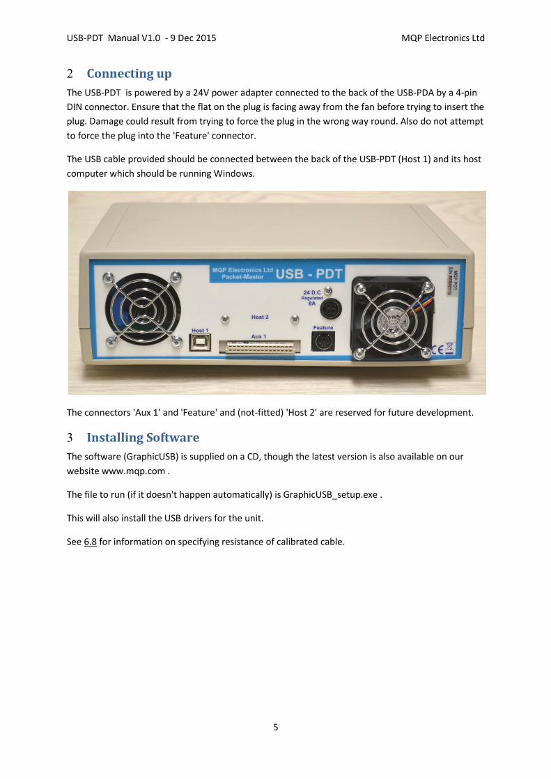
2 Connecting up
The USB-PDT is powered by a 24V power adapter connected to the back of the USB-PDA by a 4-pin
DIN connector. Ensure that the flat on the plug is facing away from the fan before trying to insert the
plug. Damage could result from trying to force the plug in the wrong way round. Also do not attempt
to force the plug into the 'Feature' connector.
The USB cable provided should be connected between the back of the USB-PDT (Host 1) and its host
computer which should be running Windows.
The connectors 'Aux 1' and 'Feature' and (not-fitted) 'Host 2' are reserved for future development.
3 Installing Software
The software (GraphicUSB) is supplied on a CD, though the latest version is also available on our
website www.mqp.com .
The file to run (if it doesn't happen automatically) is GraphicUSB_setup.exe .
This will also install the USB drivers for the unit.
See 6.8 for information on specifying resistance of calibrated cable.

USB-PDT Manual V1.0 - 9 Dec 2015 MQP Electronics Ltd
6
4 Starting up
After plugging in the cables to the back of the USB-PDT, run the GraphicUSB software.
When the Tester is ready, the Tester icon on the toolbar will be lit, and the white LED on the Tester
plug-in will also light.
Check that the unit (and its plug-in) has been recognised, by clicking Help...About GraphicUSB... and
check that the unit shows up there and its plug-in is recognised.
USB-PDT Manual V1.0 - 9 Dec 2015 MQP Electronics Ltd
7
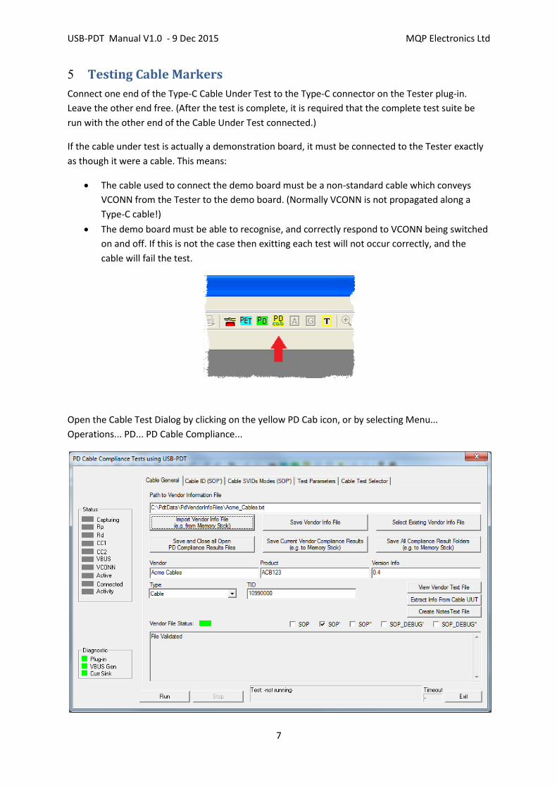
5 Testing Cable Markers
Connect one end of the Type-C Cable Under Test to the Type-C connector on the Tester plug-in.
Leave the other end free. (After the test is complete, it is required that the complete test suite be
run with the other end of the Cable Under Test connected.)
If the cable under test is actually a demonstration board, it must be connected to the Tester exactly
as though it were a cable. This means:
The cable used to connect the demo board must be a non-standard cable which conveys
VCONN from the Tester to the demo board. (Normally VCONN is not propagated along a
Type-C cable!)
The demo board must be able to recognise, and correctly respond to VCONN being switched
on and off. If this is not the case then exitting each test will not occur correctly, and the
cable will fail the test.
Open the Cable Test Dialog by clicking on the yellow PD Cab icon, or by selecting Menu...
Operations... PD... PD Cable Compliance...
USB-PDT Manual V1.0 - 9 Dec 2015 MQP Electronics Ltd
8
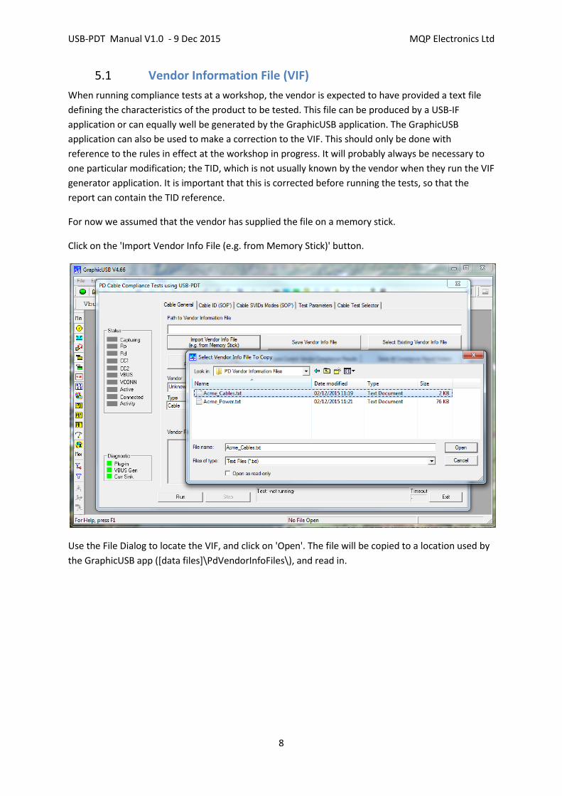
5.1 Vendor Information File (VIF)
When running compliance tests at a workshop, the vendor is expected to have provided a text file
defining the characteristics of the product to be tested. This file can be produced by a USB-IF
application or can equally well be generated by the GraphicUSB application. The GraphicUSB
application can also be used to make a correction to the VIF. This should only be done with
reference to the rules in effect at the workshop in progress. It will probably always be necessary to
one particular modification; the TID, which is not usually known by the vendor when they run the VIF
generator application. It is important that this is corrected before running the tests, so that the
report can contain the TID reference.
For now we assumed that the vendor has supplied the file on a memory stick.
Click on the 'Import Vendor Info File (e.g. from Memory Stick)' button.
Use the File Dialog to locate the VIF, and click on 'Open'. The file will be copied to a location used by
the GraphicUSB app ([data files]\PdVendorInfoFiles\), and read in.

USB-PDT Manual V1.0 - 9 Dec 2015 MQP Electronics Ltd
9
5.2 General Information Tab
The contents of the file will be validated, and the result shown in the bottom window. This report
will describe any problem with the file, to enable easy correction. 'Path to Vendor Information File'
will show the internal location allocated by the version of Windows in use.
After correcting the TID, use the 'Save Vendor Info File' button, maintaining the suggested file name
and location.
At this point, during a Workshop, it is recommended that you also use the 'Create Notes Text File'
button. This creates a pre-initialised text document for making any observations about the testing.
The file appears in the main window below this dialog. On saving, maintain the suggested file name
and location.
The boxes under the buttons show the general characteristics of the vendor information file:
Vendor Name
Product Name
TID
UUT type (must be 'Cable' in this case)
SOP* types which will be responded to with GoodCRC messages
USB-PDT Manual V1.0 - 9 Dec 2015 MQP Electronics Ltd
10
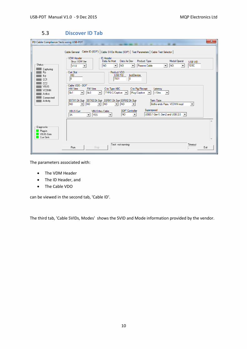
5.3 Discover ID Tab
The parameters associated with:
The VDM Header
The ID Header, and
The Cable VDO
can be viewed in the second tab, 'Cable ID'.
The third tab, 'Cable SVIDs, Modes' shows the SVID and Mode information provided by the vendor.
USB-PDT Manual V1.0 - 9 Dec 2015 MQP Electronics Ltd
11
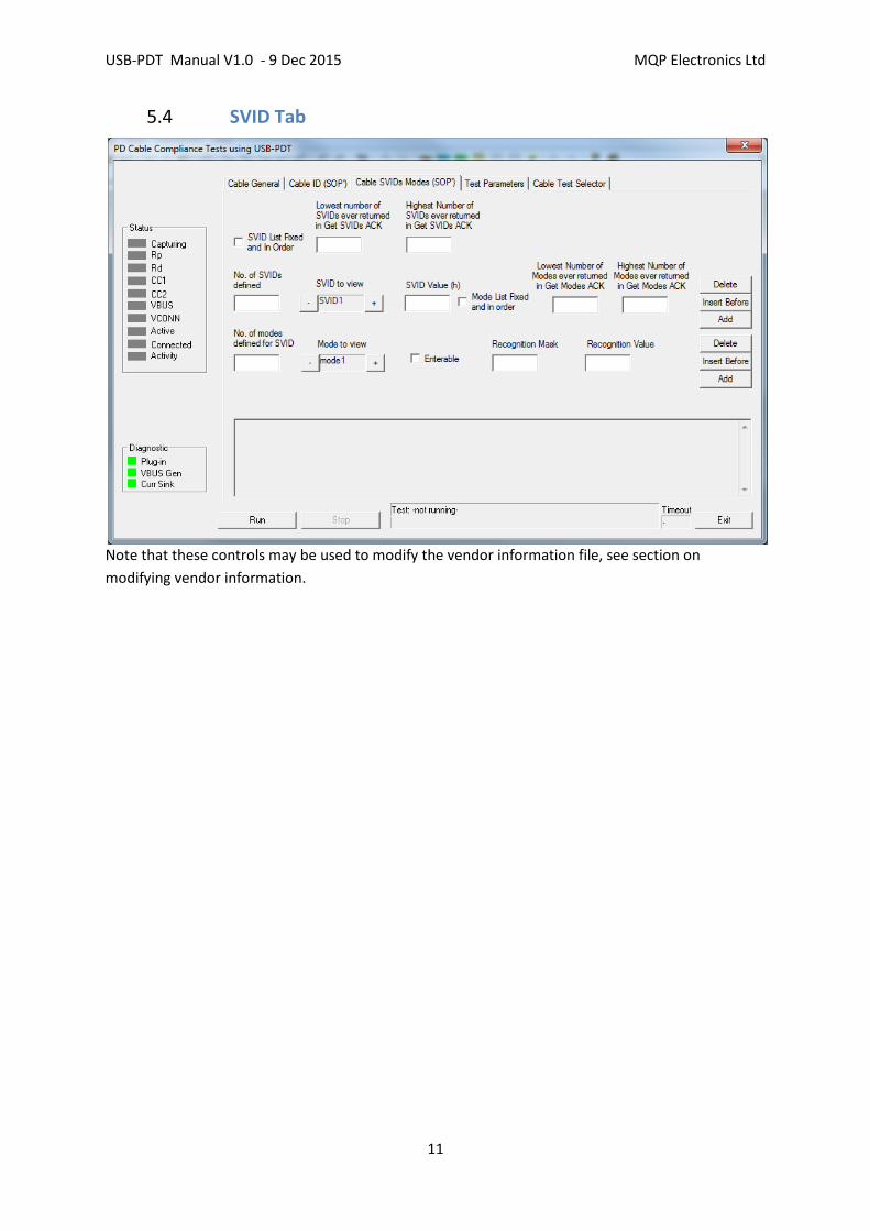
5.4 SVID Tab
Note that these controls may be used to modify the vendor information file, see section on
modifying vendor information.

USB-PDT Manual V1.0 - 9 Dec 2015 MQP Electronics Ltd
12
5.5 Test Parameter Tab
The fourth tab is for the 'Test Parameters'.
The Tx parameters define the waveform sent by the Tester transmitter:
under normal conditions
while sending BIST messages during PHY-TX-INT-REJ Group 1 noise testing
while sending BIST messages during PHY-TX-INT-REJ Group 2 noise testing
The Capture Tester Eye buttons allow the generated waveform to be displayed. This is useful as a
double check on calibration. Before clicking on this button, ensure that nothing is connected to the
plug-in panel.
The parameters relating to group 1 and 2 noise default to the Compliance Plan values, but may be
altered during development to alter the stress on the receiver.

USB-PDT Manual V1.0 - 9 Dec 2015 MQP Electronics Ltd
13
5.6 Cable Test Selector Tab
The last tab shows the selected tests (set on reading in the vendor file). Typically the SOP' tests will
all be selected, and none of the SOP'' tests.
This actually depends on the setting of the 'SOP'' Controller Present' bit in the vendor file. To avoid
running the SOP'' tests in this case, simply disable that bit (second tab), and resave the vendor info
file, before re-running the test.
Any test may be enabled or disabled, in the dialog above. This may be useful if a certain test fails to
complete for some reason.

USB-PDT Manual V1.0 - 9 Dec 2015 MQP Electronics Ltd
14
5.7 Running the tests
Click on the 'Run' button (bottom left). This will start the test running and the test name and
progress will be indicated at the bottom of the dialog. Test names will be colour-highlighted as they
are run and completed.
Allow the test to run to completion before clicking on anything. This will be indicated by the Exit
button being re-enabled.
When the tests have completed, click on 'Exit'.

USB-PDT Manual V1.0 - 9 Dec 2015 MQP Electronics Ltd
15
The test run will have created two documents:
an HTML report
an MQP Capture file (.mqu)
5.8 HTML Report
The HTML report comprises a number of sections:
Header information describing
o the test software version
o the product being tested
o The actual tests to be run
Runtime Report
This is a description of the real time procedures. Some of these may result in test failures.
Post-run Analysis Report
This is an analysis of the Analyser Capture file taken during the test run. The Capture file
stores every PD event which occurred, together with embedded 'Goals'. The file is analysed
for :
o PD timing errors
o PD protocol errors
o valid usage of all parameter fields
o match of all parameter fields with vendor supplied information
o whether embedded test goals have been achieved
Every PD message is reported on in the Post-run Analysis Report (with the exception of
multiple messages sent during the Interference Rejection tests).
USB-PDT Manual V1.0 - 9 Dec 2015 MQP Electronics Ltd
16
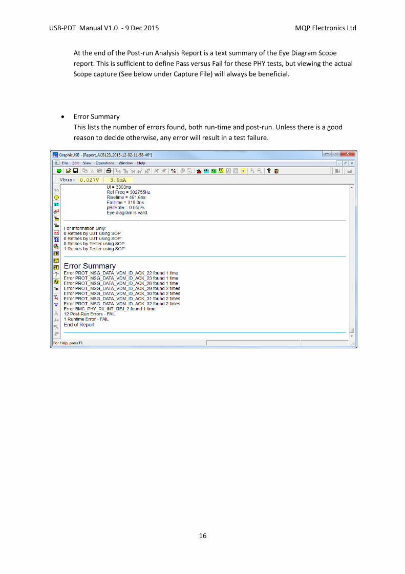
At the end of the Post-run Analysis Report is a text summary of the Eye Diagram Scope
report. This is sufficient to define Pass versus Fail for these PHY tests, but viewing the actual
Scope capture (See below under Capture File) will always be beneficial.
Error Summary
This lists the number of errors found, both run-time and post-run. Unless there is a good
reason to decide otherwise, any error will result in a test failure.

USB-PDT Manual V1.0 - 9 Dec 2015 MQP Electronics Ltd
17
In the event of an error being found, it is reported in a manner similar to the example shown above.
The word 'FAIL' will appear in the right hand column of the report.
To the left of this the error is described, both in words, and also by reference to the error code
defined in the Compliance Plan. Searching the Compliance Plan for this code will reveal the exact
clause which has been violated.

USB-PDT Manual V1.0 - 9 Dec 2015 MQP Electronics Ltd
18
5.9 Analyser Capture Report
Underneath the HTML report (use menu item Window... to find it) is the Analyser Capture report.
The left hand pane shows the PD events (use Min and Max to reveal more of less detail).
The top right hand (Detail) pane gives an analysis of the event selected in the event pane.
The pane below the Detail pane shows any data involved in the event selected.
The bottom pane shows a zoomable timeline of all the events in the complete capture.
In the example above can be seen the BIST continuous waveform on the left (in brown),
followed by two long blue lines (each containing 13000 BIST test messages during the
Interference Rejection test), followed by various other PD messages from the other tests.
Above that is a simple representation of VBUS, going between 0 and 5V.

USB-PDT Manual V1.0 - 9 Dec 2015 MQP Electronics Ltd
19
The capture file shows a complete analysis of the PD messages which were transferred. Any general
error will be shown by the use of an orange or red coloured area in the appropriate pane. Such
errors will be detailed in the Details pane.
Use the Details pane to examine every aspect of the messages captured.

USB-PDT Manual V1.0 - 9 Dec 2015 MQP Electronics Ltd
20
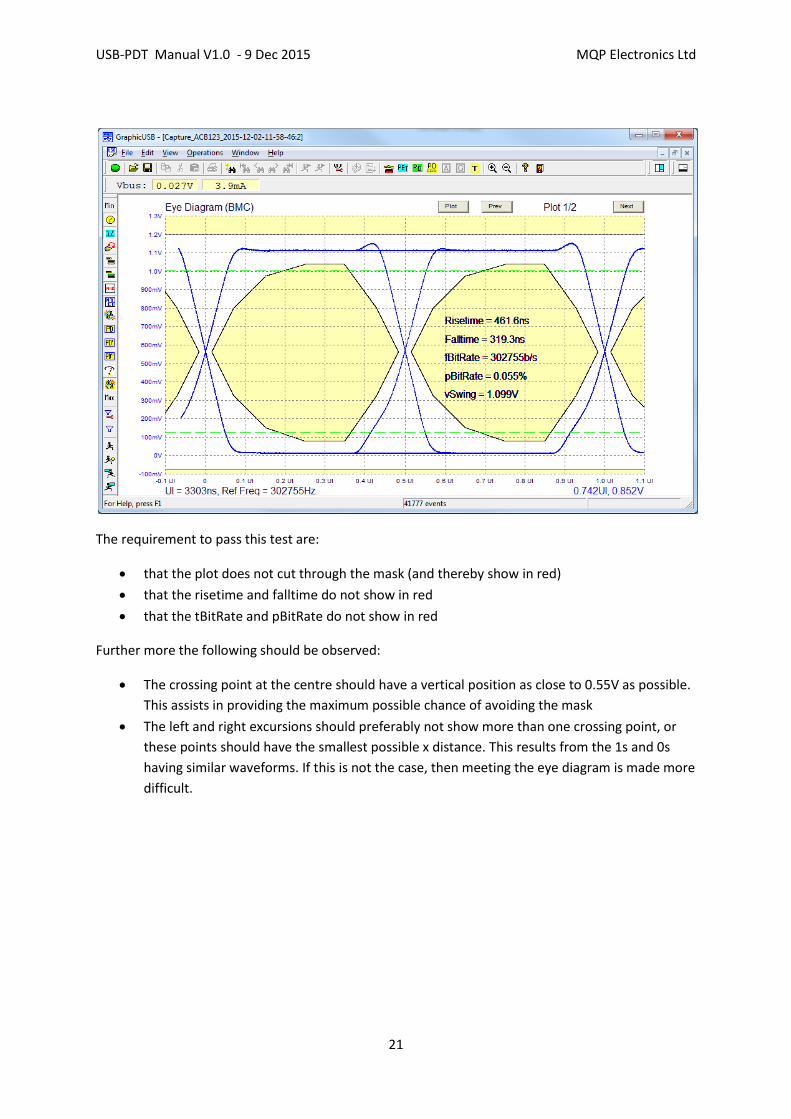
5.10 Viewing Scope Captures
At the bottom of the Event pane is the Scope Capture event. This always comes at the end, if
present. To view the scope capture, click on the Scope Capture event, then on the Show Scope
Display in the Details pane.
USB-PDT Manual V1.0 - 9 Dec 2015 MQP Electronics Ltd
21
The requirement to pass this test are:
that the plot does not cut through the mask (and thereby show in red)
that the risetime and falltime do not show in red
that the tBitRate and pBitRate do not show in red
Further more the following should be observed:
The crossing point at the centre should have a vertical position as close to 0.55V as possible.
This assists in providing the maximum possible chance of avoiding the mask
The left and right excursions should preferably not show more than one crossing point, or
these points should have the smallest possible x distance. This results from the 1s and 0s
having similar waveforms. If this is not the case, then meeting the eye diagram is made more
difficult.
USB-PDT Manual V1.0 - 9 Dec 2015 MQP Electronics Ltd
22
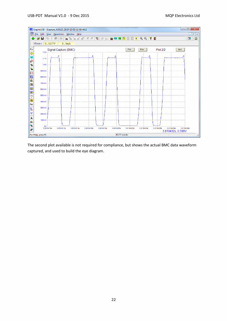
The second plot available is not required for compliance, but shows the actual BMC data waveform
captured, and used to build the eye diagram.

USB-PDT Manual V1.0 - 9 Dec 2015 MQP Electronics Ltd
23
5.11 Saving the Results Files To Disk
After viewing the report and capture documents it is required to close and save them for the record.
To do this click on the 'Save and Close all Open PD Compliance Files' button. The open documents
will be closed, and saved in a folder built from the Vendor name and the Product Name ([data files]
\[vendor]\[product]).

USB-PDT Manual V1.0 - 9 Dec 2015 MQP Electronics Ltd
24
5.12 Providing Vendor with Results Files
In order to provide the vendor with the files which have been captured for his product, insert his
Memory stick into a suitable USB socket, and click on the 'Save Current Vendor Compliance Results
(e.g. to Memory Stick)' button (see picture above).
In the dialog which appears, locate the memory stick name. Click on OK. The files will be copied to a
unique folder on the memory stick. The vendor can then take away these files on his stick.
USB-PDT Manual V1.0 - 9 Dec 2015 MQP Electronics Ltd
25
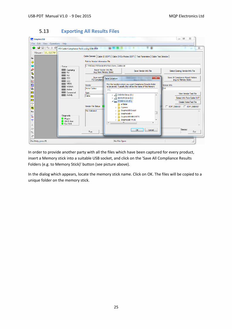
5.13 Exporting All Results Files
In order to provide another party with all the files which have been captured for every product,
insert a Memory stick into a suitable USB socket, and click on the 'Save All Compliance Results
Folders (e.g. to Memory Stick)' button (see picture above).
In the dialog which appears, locate the memory stick name. Click on OK. The files will be copied to a
unique folder on the memory stick.
USB-PDT Manual V1.0 - 9 Dec 2015 MQP Electronics Ltd
26
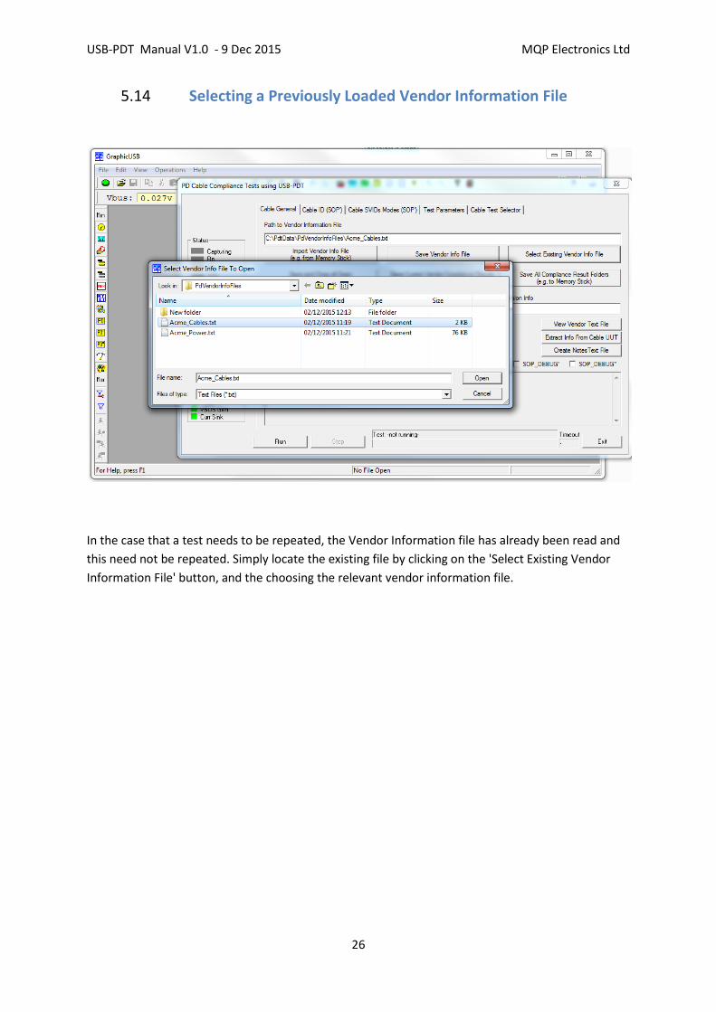
5.14 Selecting a Previously Loaded Vendor Information File
In the case that a test needs to be repeated, the Vendor Information file has already been read and
this need not be repeated. Simply locate the existing file by clicking on the 'Select Existing Vendor
Information File' button, and the choosing the relevant vendor information file.

USB-PDT Manual V1.0 - 9 Dec 2015 MQP Electronics Ltd
27
6 Testing PD Devices
Connect one end of the supplied calibrated Type-C Test Cable to the Type-C receptacle on the Tester
plug-in. Connect the other end to the Unit Under Test (UUT).
If the UUT has a captive cable, connect this to the Type-C receptacle on the Tester plug-in.
Open the Test Dialog by clicking on the green PD icon, or by selecting Menu... Operations... PD... PD
Compliance...
The PD Compliance Test dialog will open:

USB-PDT Manual V1.0 - 9 Dec 2015 MQP Electronics Ltd
28
6.1 Vendor Information File
When running compliance tests at a workshop, the vendor is expected to have provided a text file
defining the characteristics of the product to be tested. This file can be produced by a USB-IF
application or can equally well be generated by the GraphicUSB application. The GraphicUSB
application can also be used to make a correction to the VIF. This should only be done with
reference to the rules in effect at the workshop in progress. It will probably always be necessary to
one particular modification; the TID, which is not usually known by the vendor when they run the VIF
generator application. It is important that this is corrected before running the tests, so that the
report can contain the TID reference.
For now we assumed that the vendor has supplied the file on a memory stick.
Click on the 'Import Vendor Info File (e.g. from Memory Stick)' button.

USB-PDT Manual V1.0 - 9 Dec 2015 MQP Electronics Ltd
29
6.2 General Information Tab
The contents of the file will be validated, and the result shown in the bottom window. This report
will describe any problem with the file, to enable easy correction. 'Path to Vendor Information File'
will show the internal location allocated by the version of Windows in use.
After correcting the TID, use the 'Save Vendor Info File' button, maintaining the suggested file name
and location.
At this point, during a Workshop, it is recommended that you also use the 'Create Notes Text File'
button. This creates a pre-initialised text document for making any observations about the testing.
The file appears in the main window below this dialog. On saving, maintain the suggested file name
and location.
The boxes under the buttons show the general characteristics of the vendor information file:
Vendor Name
Product Name
Version Info
TID
UUT type
USB-PDT Manual V1.0 - 9 Dec 2015 MQP Electronics Ltd
30
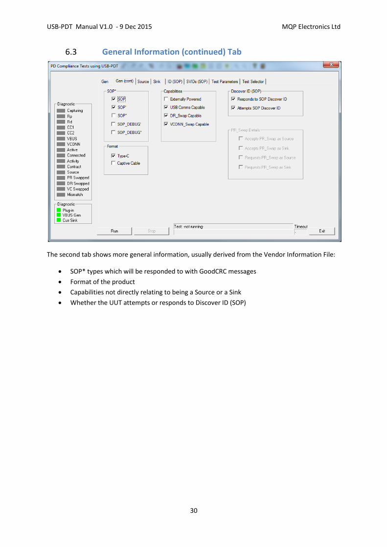
6.3 General Information (continued) Tab
The second tab shows more general information, usually derived from the Vendor Information File:
SOP* types which will be responded to with GoodCRC messages
Format of the product
Capabilities not directly relating to being a Source or a Sink
Whether the UUT attempts or responds to Discover ID (SOP)
USB-PDT Manual V1.0 - 9 Dec 2015 MQP Electronics Ltd
31
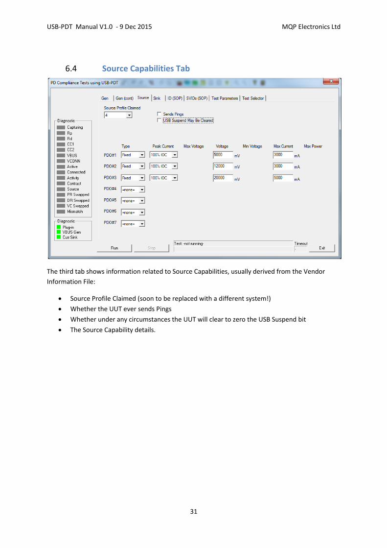
6.4 Source Capabilities Tab
The third tab shows information related to Source Capabilities, usually derived from the Vendor
Information File:
Source Profile Claimed (soon to be replaced with a different system!)
Whether the UUT ever sends Pings
Whether under any circumstances the UUT will clear to zero the USB Suspend bit
The Source Capability details.
USB-PDT Manual V1.0 - 9 Dec 2015 MQP Electronics Ltd
32
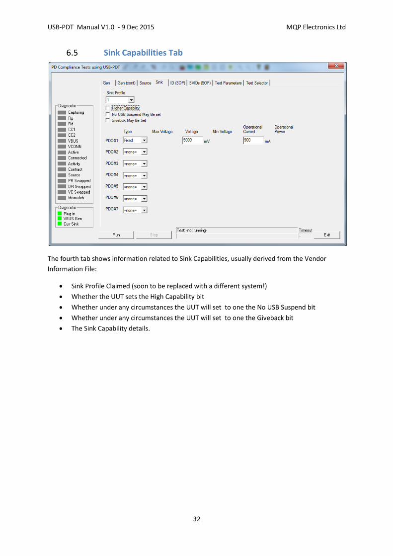
6.5 Sink Capabilities Tab
The fourth tab shows information related to Sink Capabilities, usually derived from the Vendor
Information File:
Sink Profile Claimed (soon to be replaced with a different system!)
Whether the UUT sets the High Capability bit
Whether under any circumstances the UUT will set to one the No USB Suspend bit
Whether under any circumstances the UUT will set to one the Giveback bit
The Sink Capability details.

USB-PDT Manual V1.0 - 9 Dec 2015 MQP Electronics Ltd
33
6.6 Discover ID (SOP) Tab
The fifth tab shows information related to Discover ID (SOP), usually derived from the Vendor
Information File:
VDM Header Information
ID Header Information
Cert Stat Information
Product VDO Information
AMA VDO Information

USB-PDT Manual V1.0 - 9 Dec 2015 MQP Electronics Ltd
34
6.7 SVID Tab
The sixth tab shows information related to Discover ID (SOP), usually derived from the Vendor
Information File:
SVID Information
USB-PDT Manual V1.0 - 9 Dec 2015 MQP Electronics Ltd
35
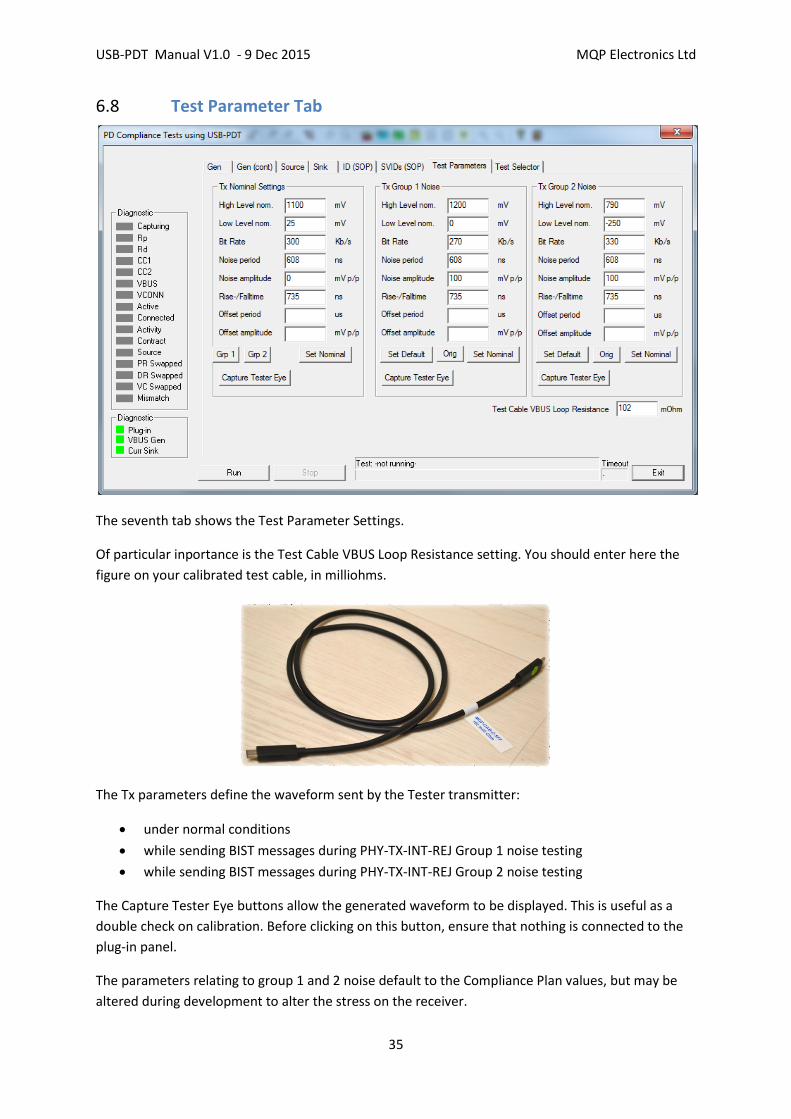
6.8 Test Parameter Tab
The seventh tab shows the Test Parameter Settings.
Of particular inportance is the Test Cable VBUS Loop Resistance setting. You should enter here the
figure on your calibrated test cable, in milliohms.
The Tx parameters define the waveform sent by the Tester transmitter:
under normal conditions
while sending BIST messages during PHY-TX-INT-REJ Group 1 noise testing
while sending BIST messages during PHY-TX-INT-REJ Group 2 noise testing
The Capture Tester Eye buttons allow the generated waveform to be displayed. This is useful as a
double check on calibration. Before clicking on this button, ensure that nothing is connected to the
plug-in panel.
The parameters relating to group 1 and 2 noise default to the Compliance Plan values, but may be
altered during development to alter the stress on the receiver.

USB-PDT Manual V1.0 - 9 Dec 2015 MQP Electronics Ltd
36
6.9 Test Selector Tab
The last tab shows the Test Selectors.
PD Tests should be run as three separate groups: PHY, Protocol and Power. This is to avoid the
resultant files becoming too large and too slow.
The 'Settings during Tests' options default to the standard required settings for a full Compliance
Test. The settings may be altered to experiment with different options. 'Sink Real Current' may be
switched off while performing PD tests on a 'Silicon Only' product.
Bypass capacitance is normally set to various default values during tests. However for development
reasons the value may be set to a specific value in this dialog.
As you may expect, any individual test may be selected, when working on a development issue.
The button 'Set All PHY Tests' causes the five PHY tests to be selected (and all others to be de-
selected). After selecting the tests, click on the 'Run' button.
You may then exit the dialog and examine the results of just the PHY tests, or continue to perform
the other two groups of tests first, depending on the situation.
USB-PDT Manual V1.0 - 9 Dec 2015 MQP Electronics Ltd
37
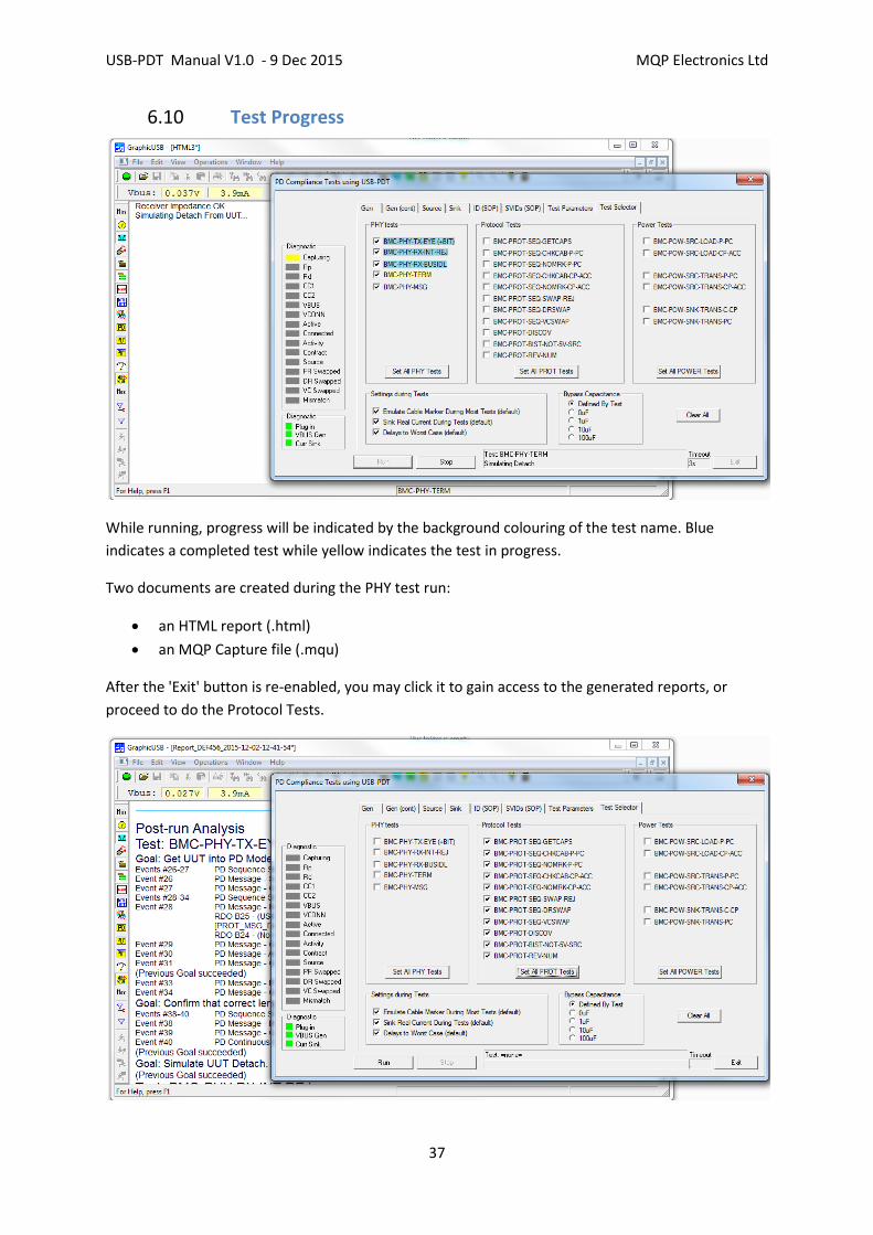
6.10 Test Progress
While running, progress will be indicated by the background colouring of the test name. Blue
indicates a completed test while yellow indicates the test in progress.
Two documents are created during the PHY test run:
an HTML report (.html)
an MQP Capture file (.mqu)
After the 'Exit' button is re-enabled, you may click it to gain access to the generated reports, or
proceed to do the Protocol Tests.

USB-PDT Manual V1.0 - 9 Dec 2015 MQP Electronics Ltd
38
6.11 Protocol Test Progress
The button 'Set All PROT Tests' causes the eleven Protocol tests to be selected (and all others to be
de-selected). Some tests may be inappropriate to the UUT Type. After selecting the tests, click on
the 'Run' button.

USB-PDT Manual V1.0 - 9 Dec 2015 MQP Electronics Ltd
39
While running, progress will be indicated by the background colouring of the test name. Blue
indicates a completed test while yellow indicates the test in progress.
Two documents are created during the Protocol test run:
an HTML report (.html)
an MQP Capture file (.mqu)
After the 'Exit' button is re-enabled, you may click it to gain access to the generated reports, or
proceed to do the Power Tests.
USB-PDT Manual V1.0 - 9 Dec 2015 MQP Electronics Ltd
40
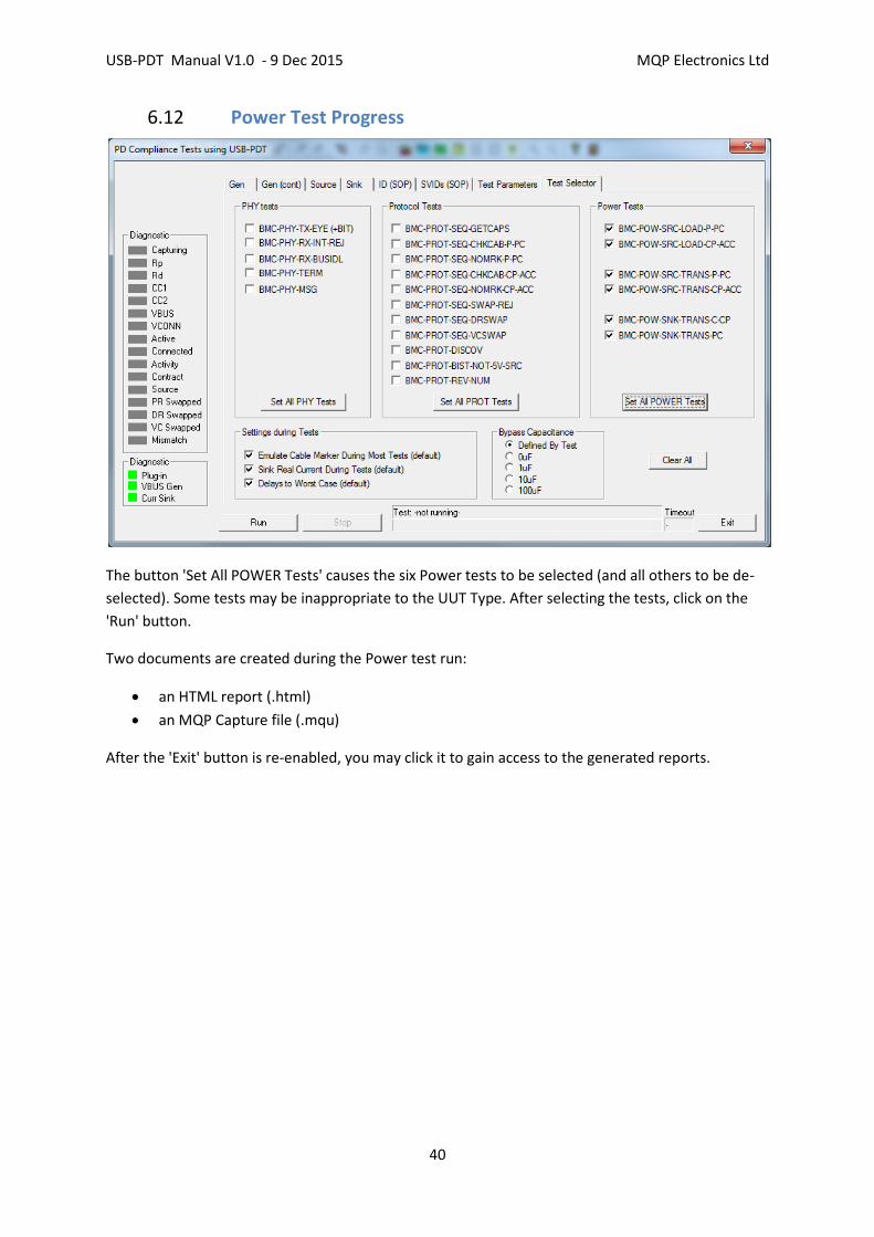
6.12 Power Test Progress
The button 'Set All POWER Tests' causes the six Power tests to be selected (and all others to be de-
selected). Some tests may be inappropriate to the UUT Type. After selecting the tests, click on the
'Run' button.
Two documents are created during the Power test run:
an HTML report (.html)
an MQP Capture file (.mqu)
After the 'Exit' button is re-enabled, you may click it to gain access to the generated reports.
USB-PDT Manual V1.0 - 9 Dec 2015 MQP Electronics Ltd
41
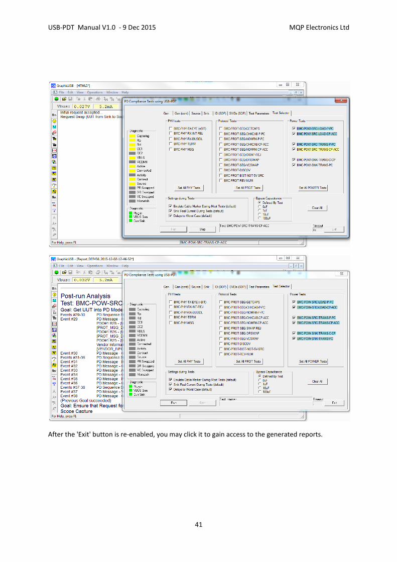
After the 'Exit' button is re-enabled, you may click it to gain access to the generated reports.

USB-PDT Manual V1.0 - 9 Dec 2015 MQP Electronics Ltd
42
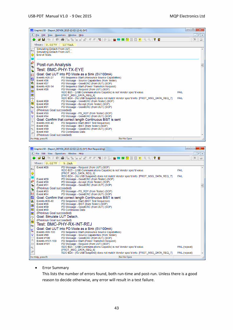
6.13 HTML Report File
The HTML report comprises a number of sections:
Header information describing
o the test software version
o the product being tested
o The actual tests to be run
Runtime Report
This is a description of the run time procedures. Some of these may result in test failures.
Post-run Analysis Report
This is an analysis of the Analyser Capture file taken during the test run. The Capture file
stores every PD event which occurred, together with embedded 'Goals'. The file is analysed
for :
o PD timing errors
o PD protocol errors
o valid usage of all parameter fields
o match of all parameter fields with vendor supplied information
o whether embedded test goals have been achieved
Every PD message is reported on in the Post-run Analysis Report (with the exception of
multiple messages sent during the Interference Rejection tests).
At the end of the Post-run Analysis Report for the PHY tests is a text summary of the Eye
Diagram Scope report. This is sufficient to define Pass versus Fail for these PHY tests, but
viewing the actual Scope capture (See below under Capture File) will always be beneficial.
USB-PDT Manual V1.0 - 9 Dec 2015 MQP Electronics Ltd
43
Error Summary
This lists the number of errors found, both run-time and post-run. Unless there is a good
reason to decide otherwise, any error will result in a test failure.

USB-PDT Manual V1.0 - 9 Dec 2015 MQP Electronics Ltd
44
USB-PDT Manual V1.0 - 9 Dec 2015 MQP Electronics Ltd
45
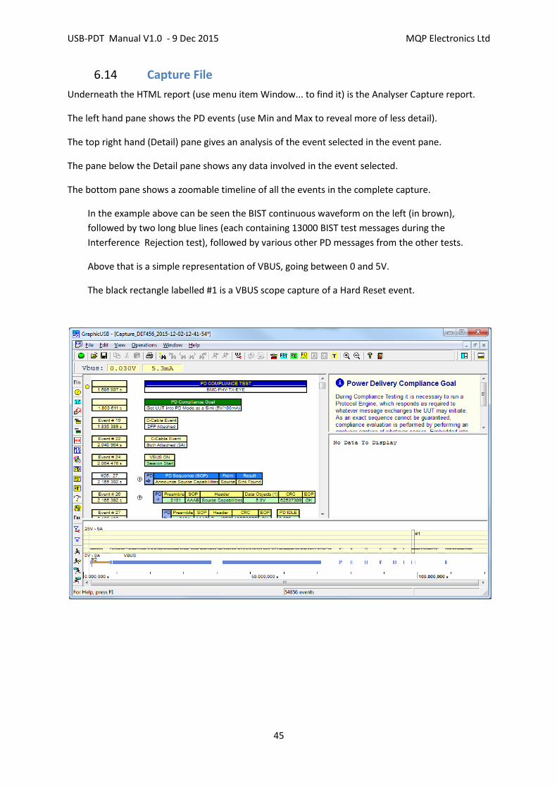
6.14 Capture File
Underneath the HTML report (use menu item Window... to find it) is the Analyser Capture report.
The left hand pane shows the PD events (use Min and Max to reveal more of less detail).
The top right hand (Detail) pane gives an analysis of the event selected in the event pane.
The pane below the Detail pane shows any data involved in the event selected.
The bottom pane shows a zoomable timeline of all the events in the complete capture.
In the example above can be seen the BIST continuous waveform on the left (in brown),
followed by two long blue lines (each containing 13000 BIST test messages during the
Interference Rejection test), followed by various other PD messages from the other tests.
Above that is a simple representation of VBUS, going between 0 and 5V.
The black rectangle labelled #1 is a VBUS scope capture of a Hard Reset event.

USB-PDT Manual V1.0 - 9 Dec 2015 MQP Electronics Ltd
46
6.15 Eye Diagram
The last event in the Events pane is the Scope Capture event #2, relating the the eye diagram. Click
on this event, then on Show Scope Display. The Eye Diagram will appear.
USB-PDT Manual V1.0 - 9 Dec 2015 MQP Electronics Ltd
47
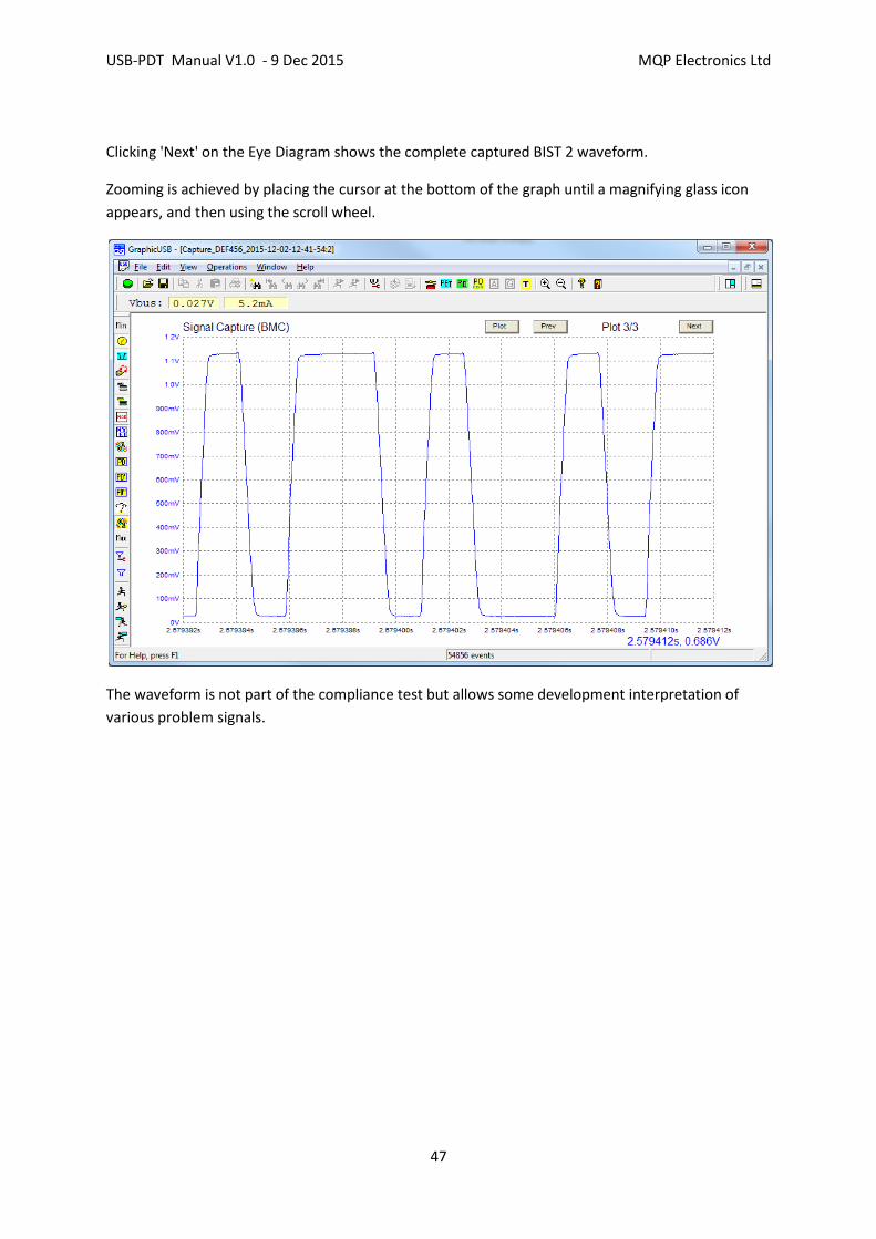
Clicking 'Next' on the Eye Diagram shows the complete captured BIST 2 waveform.
Zooming is achieved by placing the cursor at the bottom of the graph until a magnifying glass icon
appears, and then using the scroll wheel.
The waveform is not part of the compliance test but allows some development interpretation of
various problem signals.

USB-PDT Manual V1.0 - 9 Dec 2015 MQP Electronics Ltd
48
6.16 Hard Reset Scope Capture
Scope Capture #1 in this case, is a Hard Reset, generated by the tester, with VBUS controlled by the
tester. It is included here to show how a mask is automatically drawn to indicate valid areas for the
VBUS waveform. Typically the blue voltage waveform will be coloured red if the VBUS cuts through
part of the mask.

USB-PDT Manual V1.0 - 9 Dec 2015 MQP Electronics Ltd
49
6.17 Capture File Error Indications
The Capture File indicates error
USB-PDT Manual V1.0 - 9 Dec 2015 MQP Electronics Ltd
50
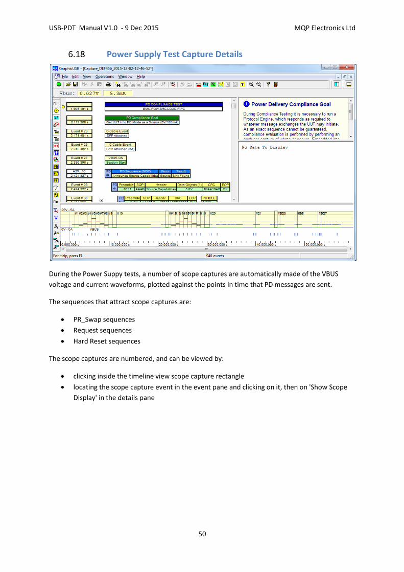
6.18 Power Supply Test Capture Details
During the Power Suppy tests, a number of scope captures are automatically made of the VBUS
voltage and current waveforms, plotted against the points in time that PD messages are sent.
The sequences that attract scope captures are:
PR_Swap sequences
Request sequences
Hard Reset sequences
The scope captures are numbered, and can be viewed by:
clicking inside the timeline view scope capture rectangle
locating the scope capture event in the event pane and clicking on it, then on 'Show Scope
Display' in the details pane

USB-PDT Manual V1.0 - 9 Dec 2015 MQP Electronics Ltd
51
6.19 VBUS Scope Capture - Hard Reset
In the above view we click on scope capture timeline rectangle #10, and see the following' Hard
Reset' scope capture. It is noticable that the mask has closed up at the left end because the voltage
fell too quickly, and the waveform therefore cuts through the mask.

USB-PDT Manual V1.0 - 9 Dec 2015 MQP Electronics Ltd
52
6.20 VBUS Scope Capture - Power Role Swap
The following scope capture shows a successful PR_Swap sequence:
Zooming in shows how the PD message positions are indicated in their exact time positions:

USB-PDT Manual V1.0 - 9 Dec 2015 MQP Electronics Ltd
53
This capture shows a Request sequence for a change of current without a voltage change. The green
line indicates a current decrease at the start of the sequence. Negative current is current sunk by the
PDT. Note that the voltage remains in specification.
The plotted voltage is calculated, on a point by point basis, to be the voltage at the source end of the
cable. This is why the calibrated cable must be used and its resistance entered into the Test
Parameter dialog: