mr-eye: high-resolution microscopy coil mri for the ... · anatomy, from basic compartmental...
TRANSCRIPT
REVIEW ARTICLE
MR-Eye: High-Resolution Microscopy Coil MRI for theAssessment of the Orbit and Periorbital Structures, Part 1:
Technique and AnatomyN.W. Dobbs, M.J. Budak, R.D. White, and I.A. Zealley
ABSTRACT
SUMMARY:Microscopy coil MR imaging of the orbits has been described previously as a technique for anatomic depiction. In thefirst part of this 2-part series, the improvement in spatial resolution that the technique offers compared with conventional MRimaging of the orbits is demonstrated. We provide a guide to implementing the technique, sharing pearls and pitfalls gleaned fromour own practice to make implementation of microscopy coil MR imaging at your own center easy. As a quick reference guide tothe small-scale structures encountered when reading the studies, a short anatomy section is included, which doubles as a showcasefor the high-quality imaging that can be obtained. In the second part, our experience of microscopy coil MR imaging in day-to-dayclinical practice takes it far beyond being a useful anatomic educational tool. Through a series of interesting cases, we highlight theadded benefit of microscopy coil MR imaging compared with standard orbital MR imaging.
ABBREVIATION: MC-MRI ¼ microscopy coil MR imaging
Imaging of orbital and periorbital structures and pathologiespresents challenges due to the various limitations intrinsic to
ultrasound, CT, and conventional MR imaging.1,2 Managementof structural pathology in and around the orbit is guided byknowledge of the compartments involved and the tissue of ori-gin.3 Both the initial surgical approach4 and subsequent recon-struction techniques are influenced by factors that can only beresolved at a very small scale, sometimes at submillimeter resolu-tion. Changes of this order cannot be resolved using CT or con-ventional head coil MR imaging, while ultrasound is limited todemonstration of soft tissues only and cannot demonstrate rela-tionships with bony structures.
The use of microscopy coil MR imaging (MC-MR imaging) todepict orbital anatomy has previously been reported, generallyfor research studies.5-7 In this 2-part article, we first aimed toequip the reader with an understanding of MC-MR imaging tech-niques to enable implementing this simple, straightforward imag-ing at his or her own institution. We also aimed to refresh and
expand the reader’s knowledge of orbital anatomy, essential forinterpretation of MC-MR images. Pearls and pitfalls of the tech-nique that we have gleaned from everyday practice are shared, tomake implementation of the technique easier.
In Part 2, in addition to using MC-MR imaging as a tool foranatomic depiction, we explore the benefits of using MC-MRimaging in everyday clinical practice. We have previouslydescribed the application of MC-MR imaging in preoperativeplanning for Mohs micrographic surgery for nasofacial skin neo-plasms.2 Collaboration with ophthalmic surgeons has extendedour practice to provide high-resolution imaging of the orbits andsurrounding structures.
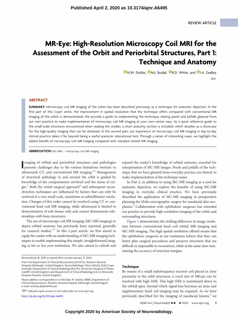
Figure 1 demonstrates the striking difference in image resolu-tion between conventional head coil orbital MR imaging andMC-MR imaging. The high spatial resolution offered means thatthe ophthalmic surgeons at our institution believe that they canbetter plan surgical procedures and preserve structures that aredifficult or impossible to reconstruct, while at the same time max-imizing the accuracy of resection margins.
TechniqueBy means of a small radiofrequency receiver coil placed in closeproximity to the orbit structures, a voxel size of 300mm can beresolved with high SNR. This high SNR is maintained down tothe orbital apex, beyond which signal loss becomes an issue andsupplementary head coil imaging may be required. As we havepreviously described for the imaging of nasofacial lesions,2 we
Received July 18, 2019; accepted after revision January 21, 2020.
From the Department of Clinical Neuroscience (N.W.D.), Western GeneralHospital, Edinburgh, United Kingdom; Qscan Radiology Clinics (M.J.B.), Gold Coast,Australia; Department of Clinical Radiology (R.D.W.), University Hospital of Wales,Cardiff, United Kingdom; and Department of Clinical Radiology (I.A.Z.), NinewellsHospital, Dundee, United Kingdom.
Please address correspondence to Nicholas W. Dobbs, MBBS, Department ofClinical Neuroscience, Western General Hospital, Edinburgh, United Kingom;e-mail: [email protected]
Indicates open access to non-subscribers at www.ajnr.org
http://dx.doi.org/10.3174/ajnr.A6495
AJNR Am J Neuroradiol �:� � 2020 www.ajnr.org 1
Published April 2, 2020 as 10.3174/ajnr.A6495
Copyright 2020 by American Society of Neuroradiology.
use a 40-mm-internal-diameter small-loop radiofrequency re-ceiver coil with a 1.5T MR imaging unit (Magnetom Avanto;Siemens, Erlangen, Germany). This has 32 receiver channelsand SQ-engine gradients (maximum gradient field strength,45mT/m; slew rate, 200 T/m/s). Sequence parameters aredescribed in the Table.
Our standard imaging consists of optimized T1-weighted andT2-weighted TSE sequences with 0.3 � 0.3mm pixel size and1.5-mm section thickness acquired with no intersection gaps.Images can be acquired in any plane depending on the structuresto be assessed. We have found that axial acquisitions are optimalto demonstrate the nasal bone, tarsal plate, optic nerve, and themedial and lateral rectus muscles. Sagittal acquisitions are usefulfor depiction of the orbital septum and the levator apparatus, aswell as the superior and inferior rectus muscles. Coronal acquisi-tions provide an excellent overview of the extraocular muscles,the optic nerve, and any intraconal lesion extension. The presenceof orbital fat around most structures means that, generally speak-ing, T1-weighted imaging delivers the best depiction of structuralinvolvement, with T2-weighted and occasionally T1-weightedfat-saturation sequences used to aid lesion characterization if thisis required.
With T1-weighted acquisitions taking .5 minutes, and T2-weighted acquisitions, .7 minutes, movement needs to be mini-mized to make the best use of the high SNR to deliver high-reso-lution imaging. Thus, while we make every effort to ensure
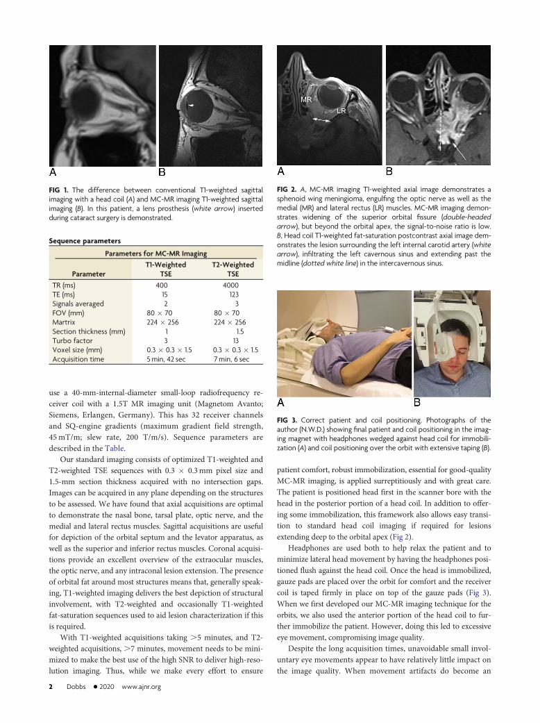
patient comfort, robust immobilization, essential for good-qualityMC-MR imaging, is applied surreptitiously and with great care.The patient is positioned head first in the scanner bore with thehead in the posterior portion of a head coil. In addition to offer-ing some immobilization, this framework also allows easy transi-tion to standard head coil imaging if required for lesionsextending deep to the orbital apex (Fig 2).
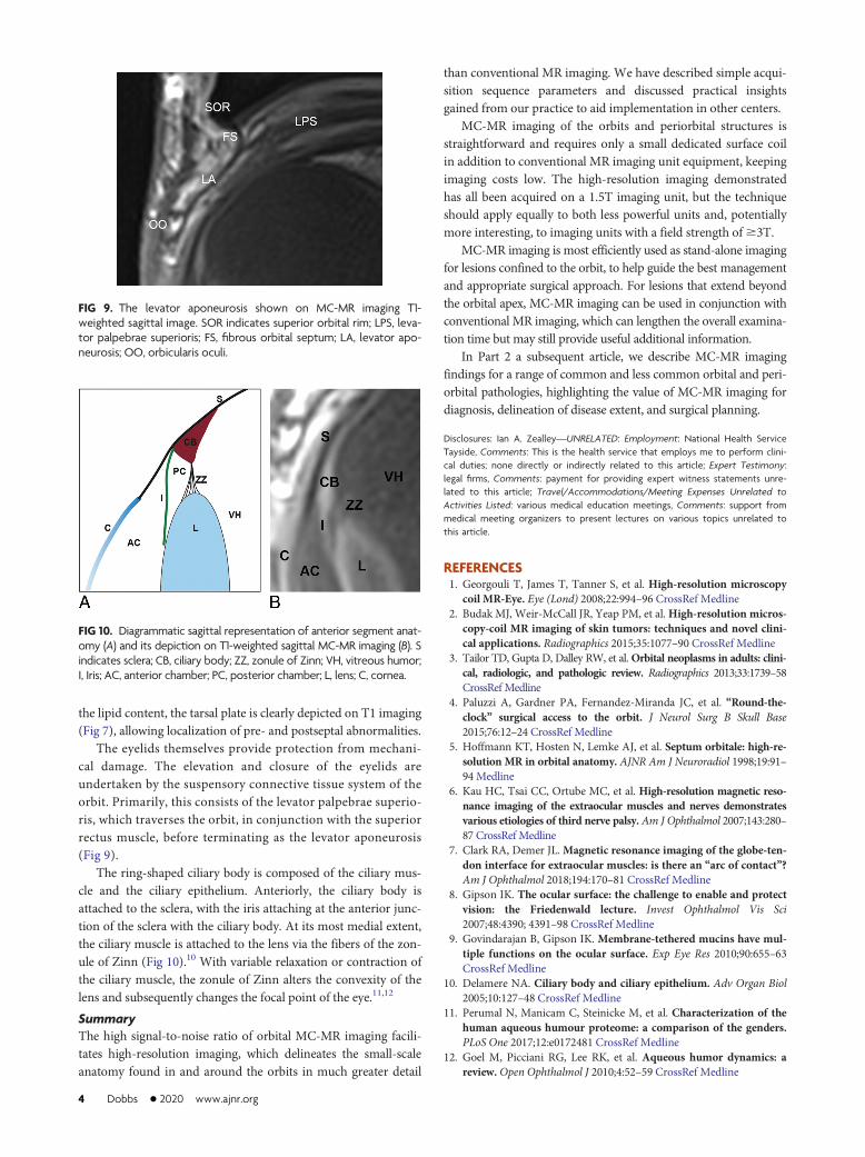
Headphones are used both to help relax the patient and tominimize lateral head movement by having the headphones posi-tioned flush against the head coil. Once the head is immobilized,gauze pads are placed over the orbit for comfort and the receivercoil is taped firmly in place on top of the gauze pads (Fig 3).When we first developed our MC-MR imaging technique for theorbits, we also used the anterior portion of the head coil to fur-ther immobilize the patient. However, doing this led to excessiveeye movement, compromising image quality.
Despite the long acquisition times, unavoidable small invol-untary eye movements appear to have relatively little impact onthe image quality. When movement artifacts do become an
FIG 1. The difference between conventional T1-weighted sagittalimaging with a head coil (A) and MC-MR imaging T1-weighted sagittalimaging (B). In this patient, a lens prosthesis (white arrow) insertedduring cataract surgery is demonstrated.
Sequence parameters
Parameters for MC-MR Imaging
ParameterT1-Weighted
TSET2-Weighted
TSETR (ms) 400 4000TE (ms) 15 123Signals averaged 2 3FOV (mm) 80 � 70 80 � 70Martrix 224 � 256 224 � 256Section thickness (mm) 1 1.5Turbo factor 3 13Voxel size (mm) 0.3 � 0.3 � 1.5 0.3 � 0.3 � 1.5Acquisition time 5min, 42 sec 7min, 6 sec
FIG 2. A, MC-MR imaging T1-weighted axial image demonstrates asphenoid wing meningioma, engulfing the optic nerve as well as themedial (MR) and lateral rectus (LR) muscles. MC-MR imaging demon-strates widening of the superior orbital fissure (double-headedarrow), but beyond the orbital apex, the signal-to-noise ratio is low.B, Head coil T1-weighted fat-saturation postcontrast axial image dem-onstrates the lesion surrounding the left internal carotid artery (whitearrow), infiltrating the left cavernous sinus and extending past themidline (dotted white line) in the intercavernous sinus.
FIG 3. Correct patient and coil positioning. Photographs of theauthor (N.W.D.) showing final patient and coil positioning in the imag-ing magnet with headphones wedged against head coil for immobili-zation (A) and coil positioning over the orbit with extensive taping (B).
2 Dobbs � 2020 www.ajnr.org

issue, taking the time to assess any causative factor or patientdiscomfort is often effective (Fig 4). Most important, no cos-metics should be worn due to the artifacts arising from metallicelements in these products, particularly mascara (Fig 5).
The capital outlay required to purchase a small-loop re-ceiver coil is small, and at Ninewells Hospital, the coil was
found unused on a shelf. The case-by-case cost is also low, witha scanner time for a 3-sequence examination of ,20minutes.We have found it best to use MC-MR imaging for the imagingof orbital lesions; through its high spatial and contrast resolu-tion, MC-MR imaging can assess the relationship of a lesion tonormal anatomic structures in detail sufficient to more confi-dently guide an appropriate clinical and surgical approach.However, the signal-to-noise ratio beyond the orbital apex islow (Fig 2). For lesions that extend beyond this point, MC-MRimaging can be used as an optional adjunct to traditional imag-ing if the extra-anatomic information provided stands to influ-ence surgical options.
Orbital AnatomyA detailed understanding of orbital anatomy is essential fordescribing the salient features that the ophthalmic surgeonrequires for diagnosis, determining the extent of disease, and pre-operative planning. MC-MR imaging allows depiction of thisanatomy, from basic compartmental anatomy (Fig 6), muscularanatomy (Fig 7A) including the complex course of the superioroblique muscle (Fig 8), and beyond.
Vision relies on a smooth refractive surface maintained by theocular surface system—a triple-layer tear film.8,9 The most super-ficial is an oily lipid layer, produced by the meibomian glands ofthe tarsal plate, which reduce evaporation from the aqueous layerbelow, which is produced by the lacrimal gland (Fig 7).8 Due to
FIG 4. Persistence pays off with movement artifacts. A, T2-weightedaxial image of the orbit with image degradation due to movementartifacts. B, The same patient and same imaging protocol, after ensur-ing patient comfort.
FIG 5. MC-MR imaging T2-weighted sagittal image degraded by me-tallic artifacts from mascara.
FIG 6. Compartmental anatomy shown by MC-MR imaging T1-weighted axial image, original on the left and annotated on the right.The solid black line indicates the orbital septum, defined by nativehigh signal of the tarsal plate; EC, extraconal space, external to the ex-traocular muscles; IC, intraconal space, inside the extraocular muscles;VH, vitreous humor, behind the lens; solid white fill, aqueous humor,anterior to the lens and ciliary muscles.
FIG 7. A, T1-weighted coronal MC-MR image. LG indicates the lacri-mal gland, positioned superolaterally in the orbit, lying directly infe-rior to the orbital rim; LP, levator palpebrae superioris muscle; SR,superior rectus muscle; SO, superior oblique tendon; MR, medial rec-tus muscle; IR, inferior rectus muscle; IO, inferior oblique muscle; LR,lateral rectus muscle; G, globe. B, T2-weighted coronal MC-MR image.In this patient, a protruding dermoid cyst (DC) caused epiphora, fillingthe nasolacrimal duct (NLD) and allowing its demonstration with highsignal on T2-weighted imaging. C, T1-weighted axial MC-MR imageillustrates the high-signal dots of the meibomian glands within thetarsal plate (TP).
FIG 8. T1-weighted MC-MR images in the coronal, sagittal, and axialplanes demonstrating the course of the superior oblique muscle andtendon (dotted line) through the trochlea (circle).
AJNR Am J Neuroradiol �:� � 2020 www.ajnr.org 3
the lipid content, the tarsal plate is clearly depicted on T1 imaging(Fig 7), allowing localization of pre- and postseptal abnormalities.
The eyelids themselves provide protection from mechani-cal damage. The elevation and closure of the eyelids areundertaken by the suspensory connective tissue system of theorbit. Primarily, this consists of the levator palpebrae superio-ris, which traverses the orbit, in conjunction with the superiorrectus muscle, before terminating as the levator aponeurosis(Fig 9).
The ring-shaped ciliary body is composed of the ciliary mus-cle and the ciliary epithelium. Anteriorly, the ciliary body isattached to the sclera, with the iris attaching at the anterior junc-tion of the sclera with the ciliary body. At its most medial extent,the ciliary muscle is attached to the lens via the fibers of the zon-ule of Zinn (Fig 10).10 With variable relaxation or contraction ofthe ciliary muscle, the zonule of Zinn alters the convexity of thelens and subsequently changes the focal point of the eye.11,12
SummaryThe high signal-to-noise ratio of orbital MC-MR imaging facili-tates high-resolution imaging, which delineates the small-scaleanatomy found in and around the orbits in much greater detail
than conventional MR imaging. We have described simple acqui-sition sequence parameters and discussed practical insightsgained from our practice to aid implementation in other centers.
MC-MR imaging of the orbits and periorbital structures isstraightforward and requires only a small dedicated surface coilin addition to conventional MR imaging unit equipment, keepingimaging costs low. The high-resolution imaging demonstratedhas all been acquired on a 1.5T imaging unit, but the techniqueshould apply equally to both less powerful units and, potentiallymore interesting, to imaging units with a field strength of$3T.
MC-MR imaging is most efficiently used as stand-alone imagingfor lesions confined to the orbit, to help guide the best managementand appropriate surgical approach. For lesions that extend beyondthe orbital apex, MC-MR imaging can be used in conjunction withconventional MR imaging, which can lengthen the overall examina-tion time but may still provide useful additional information.
In Part 2 a subsequent article, we describe MC-MR imagingfindings for a range of common and less common orbital and peri-orbital pathologies, highlighting the value of MC-MR imaging fordiagnosis, delineation of disease extent, and surgical planning.
Disclosures: Ian A. Zealley—UNRELATED: Employment: National Health ServiceTayside, Comments: This is the health service that employs me to perform clini-cal duties; none directly or indirectly related to this article; Expert Testimony:legal firms, Comments: payment for providing expert witness statements unre-lated to this article; Travel/Accommodations/Meeting Expenses Unrelated toActivities Listed: various medical education meetings, Comments: support frommedical meeting organizers to present lectures on various topics unrelated tothis article.
REFERENCES1. Georgouli T, James T, Tanner S, et al. High-resolution microscopy
coil MR-Eye. Eye (Lond) 2008;22:994–96 CrossRef Medline2. Budak MJ, Weir-McCall JR, Yeap PM, et al.High-resolution micros-
copy-coil MR imaging of skin tumors: techniques and novel clini-cal applications. Radiographics 2015;35:1077–90 CrossRef Medline
3. Tailor TD, Gupta D, Dalley RW, et al.Orbital neoplasms in adults: clini-cal, radiologic, and pathologic review. Radiographics 2013;33:1739–58CrossRef Medline
4. Paluzzi A, Gardner PA, Fernandez-Miranda JC, et al. “Round-the-clock” surgical access to the orbit. J Neurol Surg B Skull Base2015;76:12–24 CrossRef Medline
5. Hoffmann KT, Hosten N, Lemke AJ, et al. Septum orbitale: high-re-solution MR in orbital anatomy. AJNR Am J Neuroradiol 1998;19:91–94 Medline
6. Kau HC, Tsai CC, Ortube MC, et al. High-resolution magnetic reso-nance imaging of the extraocular muscles and nerves demonstratesvarious etiologies of third nerve palsy. Am J Ophthalmol 2007;143:280–87 CrossRef Medline
7. Clark RA, Demer JL.Magnetic resonance imaging of the globe-ten-don interface for extraocular muscles: is there an “arc of contact”?Am J Ophthalmol 2018;194:170–81 CrossRef Medline
8. Gipson IK. The ocular surface: the challenge to enable and protectvision: the Friedenwald lecture. Invest Ophthalmol Vis Sci2007;48:4390; 4391–98 CrossRef Medline
9. Govindarajan B, Gipson IK. Membrane-tethered mucins have mul-tiple functions on the ocular surface. Exp Eye Res 2010;90:655–63CrossRef Medline
10. Delamere NA. Ciliary body and ciliary epithelium. Adv Organ Biol2005;10:127–48 CrossRef Medline
11. Perumal N, Manicam C, Steinicke M, et al. Characterization of thehuman aqueous humour proteome: a comparison of the genders.PLoS One 2017;12:e0172481 CrossRef Medline
12. Goel M, Picciani RG, Lee RK, et al. Aqueous humor dynamics: areview.Open Ophthalmol J 2010;4:52–59 CrossRef Medline
FIG 10. Diagrammatic sagittal representation of anterior segment anat-omy (A) and its depiction on T1-weighted sagittal MC-MR imaging (B). Sindicates sclera; CB, ciliary body; ZZ, zonule of Zinn; VH, vitreous humor;I, Iris; AC, anterior chamber; PC, posterior chamber; L, lens; C, cornea.
FIG 9. The levator aponeurosis shown on MC-MR imaging T1-weighted sagittal image. SOR indicates superior orbital rim; LPS, leva-tor palpebrae superioris; FS, fibrous orbital septum; LA, levator apo-neurosis; OO, orbicularis oculi.
4 Dobbs � 2020 www.ajnr.org