mri1-iu voltage controlled time overcurrent relay (idmt, dmt) and adjusted pick up value is. the...
TRANSCRIPT

MRI1-IU - Voltage controlled time overcurrent relay

2 TD_MRI1-IU_05.04_GB
Contents 1 Introduction and application 2 Features and characteristics 3 Design
3.1 Connections 3.1.1 Analogue input circuits 3.1.2 Output relays 3.1.3 Blocking input 3.1.4 External reset input 3.2 LEDs
4 Working principle
4.1 Analogue circuits 4.2 Digital circuits 4.3 Voltage controlled tripping characteristic 4.4 Demand imposed on the main current transformers
5 Operation and setting
5.1 Display 5.2 Setting procedure 5.2.1 Current setting values for overcurrent relay (ISN and ISL) 5.2.2 Time current characteristics for phase overcurrent element (CHAR I>) 5.2.3 Trip delay or time multiplier for phase overcurrent element (tI>) 5.2.4 Reset setting for inverse time tripping characteristics in the phase current path 5.2.5 Current setting for high set element (I>>N and I>>L) 5.2.6 Trip delay for high set element (tI>>) 5.2.7 Undervoltage set reference value 5.2.8 Nominal frequency 5.2.9 Adjustment of the slave address 5.2.10 Blocking the protection functions and assignment of the output relays 5.3 Indication of measuring values and fault data 5.3.1 Indication of measuring values 5.3.2 Indication of fault data 5.4 Reset
6 Relay testing and commissioning
6.1 Power-On 6.2 Testing the output relays and LEDs 6.3 Checking the set values 6.4 Secondary injection test 6.4.1 Test equipment 6.4.2 Example of test circuit 6.4.3 Checking the input circuits and measured values 6.4.4 Checking the operating and resetting values of the relay under normal and low voltage 6.4.5 Checking the relay operating time 6.4.6 Checking the high set element 6.4.7 Checking the external blocking and reset functions 6.5 Primary injection test 6.6 Maintenance
7 Technical data
7.1 Measuring input circuits 7.2 Common data 7.3 Setting ranges and steps 7.3.1 Definite time overcurrent protection relay 7.3.2 Inverse time overcurrent protection relay 7.4 Inverse time characteristics 7.5 Output contacts
8 Order form Important: For additional common data of all MR-relays please refer to manual "MR - Digital Multifunctional relays". This technical manual is valid for software version D08-6.00.
TD_MRI1-IU_05.04_GB 3
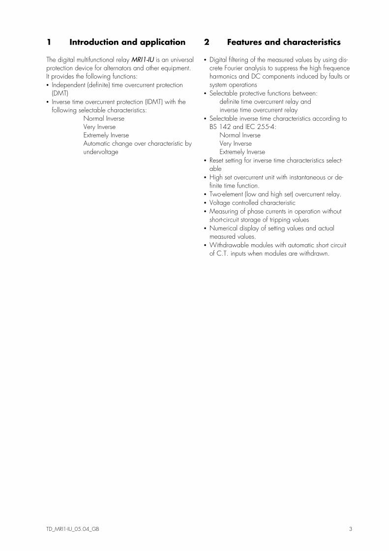
1 Introduction and application The digital multifunctional relay MRI1-IU is an universal protection device for alternators and other equipment. It provides the following functions: • Independent (definite) time overcurrent protection
(DMT) • Inverse time overcurrent protection (IDMT) with the
following selectable characteristics: Normal Inverse Very Inverse Extremely Inverse Automatic change over characteristic by undervoltage
2 Features and characteristics • Digital filtering of the measured values by using dis-
crete Fourier analysis to suppress the high frequence harmonics and DC components induced by faults or system operations
• Selectable protective functions between: definite time overcurrent relay and inverse time overcurrent relay
• Selectable inverse time characteristics according to BS 142 and IEC 255-4: Normal Inverse Very Inverse Extremely Inverse
• Reset setting for inverse time characteristics select-able
• High set overcurrent unit with instantaneous or de-finite time function.
• Two-element (low and high set) overcurrent relay. • Voltage controlled characteristic • Measuring of phase currents in operation without
short-circuit storage of tripping values • Numerical display of setting values and actual
measured values. • Withdrawable modules with automatic short circuit
of C.T. inputs when modules are withdrawn.
4 TD_MRI1-IU_05.04_GB
3 Design 3.1 Connections
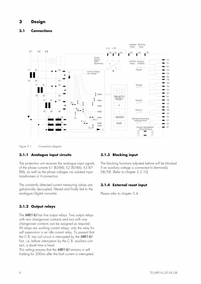
Figure 3.1: Connection diagram
3.1.1 Analogue input circuits The protection unit receives the analogue input signals of the phase currents IL1 (B3-B4), IL2 (B5-B6), IL3 B7-B8)), as well as the phase voltages via isolated input transformers in V-connection. The constantly detected current measuring values are galvanically decoupled, filtered and finally fed to the analogue/digital converter. 3.1.2 Output relays The MRI1-IU has five output relays. Two output relays with two change-over contacts and two with one change-over contacts can be assigned as required. All relays are working current relays, only the relay for self supervision is an idle current relay. To prevent that the C.B. trip coil circuit is interrupted by the MRI1-IU first, i.e. before interruption by the C.B. auxiliary con-tact, a dwell time is fixed. This setting ensures that the MRI1-IU remains in self holding for 200ms after the fault current is interrupted.
3.1.3 Blocking input The blocking functions adjusted before will be blocked if an auxiliary voltage is connected to (terminals) D8/E8. (Refer to chapter 5.2.10) 3.1.4 External reset input Please refer to chapter 5.4.

TD_MRI1-IU_05.04_GB 5
3.2 LEDs The LEDs left from the display are partially bi-coloured, the green indicating measuring, and the red fault indi-cation. The LED marked with letters RS lights up during setting of the slave address of the device for serial data com-munication. The 5 LEDs arranged at the characteristic points on the setting curves support the comfortable setting menu se-lection.
Figure 3.2: Front panel
4 Working principle 4.1 Analogue circuits The incoming currents from the main current transform-ers on the protected object are converted to voltage signals in proportion to the currents via the input trans-formers and burden. The noise signals caused by in-ductive and capacitive coupling are suppressed by an analogue R-C filter circuit. The analogue voltage signals are fed to the A/D-converter of the microprocessor and transformed to digital signals through Sample- and Hold-circuits. The analogue signals are sampled at 50 Hz (60 Hz) with a sampling frequency of 800 Hz (960 Hz), namely, a sampling rate of 1.25 ms (1.04 ms) for every measur-ing quantity. (16 scans per period). The incoming voltages from the main voltage trans-formers are led to operational amplifiers through the input transformers and R-C filters.
Figure 4.1: Block diagram

6 TD_MRI1-IU_05.04_GB
4.2 Digital circuits The essential part of the MRI1-IU relay is a powerful microcontroller. All of the operations, from the ana-logue digital conversion to the relay trip decision, are carried out by the microcontroller digitally. The relay program is located in an EPROM (Electrically-Programmable-Read-Only-Memory). With this program the CPU of the microcontroller calculates the three phase currents in order to detect a possible fault situa-tion in the protected object. For the calculation of the current value an efficient digi-tal filter based on the Fourier Transformation (DFFT - Discrete Fast Fourier Transformation) is applied to sup-press high frequency harmonics and DC components caused by fault-induced transients or other system dis-turbances. The calculated actual current values are compared with the relay settings. If a phase current exceeds the pickup value, an alarm is given and after the set trip delay has elapsed, the corresponding trip relay is acti-vated. The relay setting values for all parameters are stored in a parameter memory (EEPROM - Electrically Erasable Programmable Read-only Memory), so that the actual relay settings cannot be lost, even if the power supply is interrupted. The microprocessor is supervised by a built-in "watch-dog" timer. In case of a failure the watchdog timer re-sets the microprocessor and gives an alarm signal, via the output relay "self supervision". selection of current transformers. It implies that, if an electromechanical relay is replaced by MRI1, a high accuracy limit factor is automatically obtained by using the same current transformer. 4.3 Voltage controlled tripping characteristic The voltage controlled time overcurrent relay MRI1-IU is the combination of a time overcurrent relay (basic unit MRI1) and an additional undervoltage supervision unit. The undervoltage supervision unit has an influence on the tripping delay of the overcurrent and short-circuit steps by switching two setting points. In normal opera-tion (at nominal voltage) the MRI1-IU operates like a normal time overcurrent relay with preselected tripping characteristic (IDMT, DMT) and adjusted pick up value IS. The following diagram explains the switching-over to another IS value. ISN is the pickup value during nor-mal operation and ISL at undervoltage (low voltage).
Switching-over at undervoltage (Example ISL = 0.5)
0.4 0.6 0.8 11 2 4 6 8 1010 20I/IN
1
1010
100100
t[s]
1.0
1.0
tI>=
ISL=0.5
ISN=1.0
In case of failure (short-circuit of the alternator) the al-ternator voltage decreases. The MRI1-IU will recognise this and then switch over without delay to a lower pickup value IS. The value ISL can be adjusted. As a result, shorter tripping periods of the overcurrent and short-circuit step can be achieved. The adjusted trip-ping characteristics (normal inverse, very inverse, ex-tremely inverse or DMT is maintained). Setting ranges see in 7.3. 4.4 Demand imposed on the main current transformers The current transformers have to be rated in such a way, that a saturation should not occur within the fol-lowing operating current ranges: Independent time overcurrent function: K1 = 2 Inverse time overcurrent function: K1 = 20 High-set function: K1 = 1.2 - 1.5 K1 = Current factor related to set value Moreover, the current transformers have to be rated according to the maximum expected short circuit cur-rent in the network or in the protected objects. The low power consumption in the current circuit of MRI1, namely <0,2 VA, has a positive effect on the selection of current transformers. It implies that, if an electromechanical relay is replaced by MRI1, a high accuracy limit factor is automatically obtained by using the same current transformer.
TD_MRI1-IU_05.04_GB 7
5 Operation and setting 5.1 Display
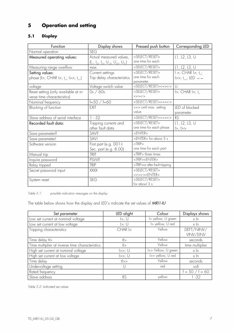
Function Display shows Pressed push button Corresponding LED Normal operation SEG Measured operating values: Actual measured values,
(IL1, IL2, IL3, U12, U23, U31) <SELECT/RESET> one time for each
L1, L2, L3, U
Measuring range overflow max. <SELECT/RESET> L1, L2, L3, U Setting values: phase (I>; CHAR I>; tI>; I>>; tI>>)
Current settings Trip delay characteristics
<SELECT/RESET> one time for each parameter
I >; CHAR I>; tI>; I>>; tI>>; LED →←
voltage Voltage switch value <SELECT/RESET><+><-> U Reset setting (only available at in-verse time characteristics)
0s / 60s <SELECT/RESET> <+><->
I>; CHAR I>; tI>
Nominal frequency f=50 / f=60 <SELECT/RESET><+><-> Blocking of function EXIT <+> until max. setting
value LED of blocked parameter
Slave address of serial interface 1 - 32 <SELECT/RESET><+><-> RS Recorded fault data: Tripping currents and
other fault data <SELECT/RESET> one time for each phase
L1, L2, L3, U I>, I>>
Save parameter? SAV? <ENTER> Save parameter! SAV! <ENTER> for about 3 s Software version First part (e.g. D01-)
Sec. part (e.g. 8.00) <TRIP> one time for each part
Manual trip TRI? <TRIP> three times Inquire password PSW? <TRIP><ENTER> Relay tripped TRIP <TRIP>or after fault tripping Secret password input XXXX <SELECT/RESET>
<+><-><ENTER>
System reset SEG <SELECT/RESET> for about 3 s
Table 5.1: possible indication messages on the display
The table below shows how the display and LED´s indicate the set values of MRI1-IU
Set parameter LED alight Colour Displays shows Low set current at nominal voltage I>; U I> yellow, U green x In Low set current at low voltage I>; U I> yellow, U red x In Tripping characteristics CHAR I> Yellow DEFT/NINV/
VINV/EINV Time delay tI> tI> Yellow seconds Time multiplier at inverse time characteristics tI> Yellow time multiplier High set current at nominal voltage I>>; U I>> Yellow, U green x In High set current at low voltage I>>; U I>> yellow, U red x In Time delay tI>> Yellow seconds Undervoltage setting U red volt Rated frequency f = 50 / f = 60 Slave address RS yellow 1 -32
Table 5.2: Indicated set values

8 TD_MRI1-IU_05.04_GB
5.2 Setting procedure After push button <SELECT/RESET> has been pressed, always the next measuring value is indicated. Firstly the operating measuring values are indicated and then the setting parameters. By pressing the <ENTER> push button the setting values can directly be called up and changed. 5.2.1 Current setting values for overcurrent relay (ISN und ISL) When adjusting the setting values ISN (during normal operation) and ISL (during undervoltage) the values shown on the display are related to the nominal cur-rent IN. This means: Pickup current (ISN) = displayed value x rated current (IN) e.g. if displayed value = 1.25, then Is = 1.25 x IN. The pickup of the relay is indicated by the flashing LED I>. LED U flashes red. The pickup value ISL is also indicated by the flashing LED I>. LED U however flashes red.
5.2.2 Time current characteristics for phase overcurrent element (CHAR I>) By setting this parameter, one of the following 4 messages appears on the display: DEFT - Definite Time NINV - Normal Inverse VINV - Very Inverse EINV - Extremely Inverse Anyone of these four characteristics can be chosen by using <+> <->-push buttons, and can be stored by us-ing <ENTER>-push button. 5.2.3 Trip delay or time multiplier for phase overcurrent element (tI>) Usually, after the characteristic is changed, the time delay or the time multiplier should be changed accord-ingly. In order to avoid an unsuitable arrangement of relay modes due to carelessness of the operator, the following precautions are taken: After the characteristic setting, the setting process turns to the time delay setting automatically. The LED tI> is going to flash yellow to remind the operator to change the time delay setting accordingly. After pressing the <SELECT>-push button, the present time delay setting value is shown on the display. The new setting value can then be changed by using <+> <-> -push buttons. If, through a new setting, another relay characteristic other than the old one has been chosen (e.g. from DEFT to NINV), but the time delay setting has not been changed despite the warning from the flashing LED, the relay will be set to the most sensitive time setting value of the selected characteristics after five minutes warning of flashing LED tI>. The most sensitive time set-ting value means the fastest tripping for the selected re-lay characteristic.

TD_MRI1-IU_05.04_GB 9
5.2.4 Reset setting for inverse time tripping characteristics in the phase current path To ensure tripping, even with recurring fault pulses shorter than the set trip delay, the reset mode for in-verse time tripping characteristics can be switched over. If the adjustment tRST is set at 60s, the tripping time is only reset after 60s faultless condition. This function is not available if tRST is set to 0. With fault current cease the trip delay is reset immediately and started again at recurring fault current. 5.2.5 Current setting for high set element (I>>N und I>>L) The current setting value of this parameter appearing on the display is related to the nominal current of the relay This means: I>> = displayed value x IN. The response value I>>N is indicated by flashing the LED I>>. LED U flashes green. The response value I>>L is also indicated by flashing the LED I>>. LED U however flashes red. When the current setting for high set element is set out of range (on display appears "EXIT"), the high set ele-ment of the overcurrent relay is blocked. The high set element can be blocked via terminals E8/D8 if the corresponding blocking parameter is set to bloc. 5.2.6 Trip delay for high set element (tI>>) Independent from the chosen tripping characteristic for I>, the high set element I>> has always a definite-time tripping characteristic. An indication value in seconds appears on the display.
5.2.7 Undervoltage set reference value When adjusting the undervoltage switching point a value in volt is shown on the display. The LED U flashes red during the setting. 5.2.8 Nominal frequency The adapted FFT-algorithm requires the nominal fre-quency as a parameter for correct digital sampling and filtering of the input currents. By pressing <SELECT> the display shows "f=50" or "f=60". The desired nominal frequency can be ad-justed by <+> or <-> and then stored with <ENTER>. 5.2.9 Adjustment of the slave address Pressing push buttons <+> and <-> the slave address can be set in range of 1-32.

10 TD_MRI1-IU_05.04_GB
5.2.10 Blocking the protection functions and assignment of the output relays Blocking the protection functions: The blocking function of the MRI1-IU can be set ac-cording to requirement. By applying the aux. voltage to D8/E8, the functions chosen by the user are blocked. Setting of the parameter should be done as follows: • When pressing push buttons <ENTER> and <TRIP>
at the same time, message "BLOC" is displayed (i.e. the respective function is blocked) or "NO_B" (i.e. the respective function is not blocked). The LED allocated to the first protection function I> lights red.
• By pressing push buttons <+> <-> the value dis-played can be changed.
• The changed value is stored by pressing <ENTER> and entering the password.
• By pressing the <SELECT/RESET> push button, any further protection function which can be blocked is displayed.
• Thereafter the blocking menu is left by pressing <SELECT/RESET> again.
Function Display LED/Colour I> Overcurrent
(Low set) NO_B I> yellow
I>> Overcurrent (High set)
BLOC I>> yellow
Table 5.3: Default settings of blocking functions
Assignment of the output relays: The relay has five output relays. The fifth output relay is provided as permanent alarm relay for self supervision is normally on. Output relays 1 - 4 are normally off and can be assigned as alarm or tripping relays to the current functions which can either be done by using the push buttons on the front plate or via serial inter-face RS485. The assignment of the output relays is similar to the setting of parameters, however, only in the assignment mode. The assignment mode can be reached only via the blocking mode. By pressing push button <SELECT/RESET> in blocking mode again, the assignment mode is selected.
The relays are assigned as follows: LEDs I>, I>>, are two-coloured and light up green when the output re-lays are assigned as alarm relays and red as trip-ping relays. Definition: Alarm relays are activated at pickup. Tripping relays are only activated after elapse of the tripping delay. After the assignment mode has been activated, first LED I> lights up green. Now one or several of the four output relays can be assigned to current element I> as alarm relays. At the same time the selected alarm re-lays for frequency element 1 are indicated on the dis-play. Indication "1_ _ _" means that output relay 1 is assigned to this current element. When the display shows "_ _ _ _", no alarm relay is assigned to this cur-rent element. The assignment of output relays 1 - 4 to the current elements can be changed by pressing <+> and <-> push buttons. The selected assignment can be stored by pressing push button <ENTER> and subse-quent input of the password. By pressing push button <SELECT/RESET>, LED I> lights up red. The output re-lays can now be assigned to this current element as tripping relays. Relays 1 - 4 are selected in the same way as de-scribed before. By repeatedly pressing of the <SELECT/RESET> push button and assignment of the relays all elements can be assigned separately to the relays. The assignment mode can be terminated at any time by pressing the <SELECT/RESET> push button for some time (abt. 3 s). Note: • The function of jumper J2 described in general de-
scription "MR Digital Multifunctional Relays" has no function. For relays without assignment mode this jumper is used for parameter setting of alarm relays (activation at pickup or tripping).
• A form is attached to this description where the set-ting requested by the customer can be filled-in. This form is prepared for telefax transmission and can be used for your own reference as well as for tele-phone queries.
Relay function Output relays Display- Lighted LED
1 2 3 4 indication I> alarm X _ 2 _ _ I>: green tripping X 1 _ _ _ tI>: red I>> alarm X _ _ 3 _ I>>: green tripping X 1 _ _ _ tI>>: red Table 5.4: Example of assignment matrix of the output relay (default settings).

TB MRI1-IU 10.98 E 11
5.3 Indication of measuring values and fault data 5.3.1 Indication of measuring values The following measuring quantities can be indicated on the display during normal service: • Apparent current in phase 1 (LED L1 green) • Apparent current in phase 2 (LED L2 green) • Apparent current in phase 3 (LED L3 green) • Phase to phase voltage U12 (LED L1, L2, U green) • Phase to phase voltage U23 (LED L1, L3, U green) • Phase to phase voltage U31 (LED L1, L3, U green) 5.3.2 Indication of fault data All of the faults detected by the relay are indicated on the front panel optically. The three phase LEDs L1, L2, L3, the undervoltage LED U and the two function LEDs I>, I>> are used to indicate the fault events. At the time when a certain relay function is energised by a fault, the corresponding function LED lights up yel-low. At the same time, the phase LED(s) is (are) flash-ing red to indicate the faulty phase(s). After the time delay is expired, the relay tripps, the LED(s) for faulty phase(s) indication turn(s) to a steady red light.
5.4 Reset Unit MRI1-IU has the following three possibilities to re-set the display of the unit as well as the output relay at jumper position J3=ON. Manual Reset • Pressing the push button <SELECT/RESET> for some
time (about 3 s) Electrical Reset • Through applying auxiliary voltage to C8/D8 Software Reset • The software reset has the same effect as the
<SELECT/RESET> push button (see also communica-tion protocol of RS485 interface).
The display can only be reset when the pickup is not present anymore (otherwise "TRIP" remains in display). During resetting of the display the parameters are not affected.

12 TD_MRI1-IU_05.04_GB
6 Relay testing and commissioning The test instructions following below help to verify the protection relay performance before or during commis-sioning of the protection system. To avoid a relay damage and to ensure a correct relay operation, be sure that: • the auxiliary power supply rating corresponds to the
auxiliary voltage on site. • the rated current and rated voltage of the relay cor-
respond to the plant data on site. • the current transformer circuits and voltage trans-
former circuits are connected to the relay correctly. • all signal circuits and output relay circuits are con-
nected correctly. 6.1 Power-On NOTE! Prior to switch on the auxiliary power supply, be sure that the auxiliary supply voltage corresponds with the rated data on the type plate. Switch on the auxiliary power supply to the relay and check that the message "ISEG" appears on the display and the self supervision alarm relay (watchdog) is en-ergised (Contact terminals D7 and E7 closed). 6.2 Testing the output relays and LEDs NOTE! Prior to commencing this test, interrupt the trip circuit to the circuit breaker if tripping is not desired. By pressing the push button <TRIP> once, the display shows the first part of the software version of the relay (e.g. „D08-“). By pressing the push button <TRIP> twice, the display shows the second part of the soft-ware version of the relay (e.g. „4.01“). The software version should be quoted in all correspondence. Press-ing the <TRIP> button once more, the display shows "PSW?". Please enter the correct password to proceed with the test. The message "TRI?" will follow. Confirm this message by pressing the push button <TRIP> again. All output relays and LEDs should then be acti-vated and the self supervision alarm relay (watchdog) be deactivated one after another with a time interval of 3 second. Thereafter, reset all output relays back to their normal positions by pressing the push button <SELECT/RESET> (about 3 s).
6.3 Checking the set values By repeatedly pressing the push button <SELECT>, all relay set values may be checked. Set value modifica-tion can be done with the push button <+><-> and <ENTER>. For detailed information about that, please refer to chapter 5. For a correct relay operation, be sure that the fre-quency set value (f=50/60) has been selected ac-cording to your system frequency (50 or 60 Hz). 6.4 Secondary injection test 6.4.1 Test equipment • Voltmeter, Ammeter with class 1 or better • Auxiliary power supply with the voltage correspond-
ing to the rated data on the type plate • Single-phase current supply unit (adjustable from
0 to ≥ 4 x In) • Three-phase voltage supply unit (adjustable from 0 to
≥ 1.2 x Un) • Timer to measure the operating time
(Accuracy class ≤ ±10 ms) • Switching device • Test leads and tools

TD_MRI1-IU_05.04_GB 13
6.4.2 Example of test circuit for MRI1-IU relays without directional feature For testing MRI1-IU relays current and voltage input signals are required. Figure 6.1 shows an example of a test circuit connected to the MRI1-IU relay under test. For testing relays with voltage controlled feature, three phase voltages from a variable voltage source should be applied to the relay with a V-connection as shown in the diagram.
The three phase voltage should be adjustable within the effective operating range of the undervoltage ele-ment and have a phase relationship apart from 120°. The current inputs could be single or three phase.
Figure 6.1: Test curcuit
6.4.3 Checking the input circuits and measured values Apply three phase rated voltage (e.g. 100 V phase to phase) to the voltage input circuits (terminals A3, A5, A7) and inject a current, which is less than the relay pickup current set values, in phase 1 (terminals B3-B4), and check the measured current on the display by pressing the push button <SELECT/RESET>. For a re-lay with rated current In = 5A, for example, a secon-dary current injection of 1A should be indicated on the display with about 0.2 (0.2 x In). The voltage will be indicated on the display in volts. The current can be also injected into the other current input circuits (Phase 2: terminals B5-B6, Phase 3: terminals B7-B8).
Compare the displayed current and voltage value with the reading of the ammeter and voltmeter. The devia-tion must not exceed 3%. By using an RMS-metering instrument, a greater deviation may be observed if the test current contains harmonics. Because the MRI1-IU relay measures only the fundamental component of the input signals, the harmonics will be rejected by the in-ternal DFFT-digital filter. Whereas the RMS-metering in-strument measures the RMS-value of the input signals.
14 TD_MRI1-IU_05.04_GB
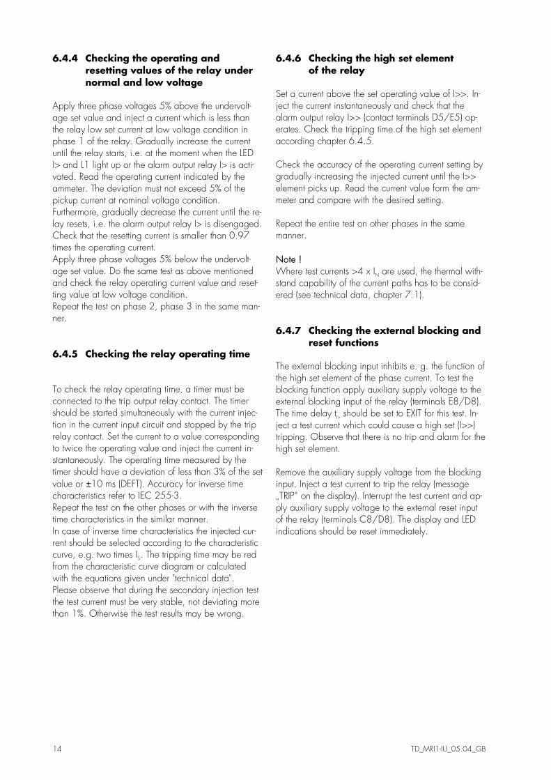
6.4.4 Checking the operating and resetting values of the relay under normal and low voltage Apply three phase voltages 5% above the undervolt-age set value and inject a current which is less than the relay low set current at low voltage condition in phase 1 of the relay. Gradually increase the current until the relay starts, i.e. at the moment when the LED I> and L1 light up or the alarm output relay I> is acti-vated. Read the operating current indicated by the ammeter. The deviation must not exceed 5% of the pickup current at nominal voltage condition. Furthermore, gradually decrease the current until the re-lay resets, i.e. the alarm output relay I> is disengaged. Check that the resetting current is smaller than 0.97 times the operating current. Apply three phase voltages 5% below the undervolt-age set value. Do the same test as above mentioned and check the relay operating current value and reset-ting value at low voltage condition. Repeat the test on phase 2, phase 3 in the same man-ner. 6.4.5 Checking the relay operating time To check the relay operating time, a timer must be connected to the trip output relay contact. The timer should be started simultaneously with the current injec-tion in the current input circuit and stopped by the trip relay contact. Set the current to a value corresponding to twice the operating value and inject the current in-stantaneously. The operating time measured by the timer should have a deviation of less than 3% of the set value or ±10 ms (DEFT). Accuracy for inverse time characteristics refer to IEC 255-3. Repeat the test on the other phases or with the inverse time characteristics in the similar manner. In case of inverse time characteristics the injected cur-rent should be selected according to the characteristic curve, e.g. two times IS. The tripping time may be red from the characteristic curve diagram or calculated with the equations given under "technical data". Please observe that during the secondary injection test the test current must be very stable, not deviating more than 1%. Otherwise the test results may be wrong.
6.4.6 Checking the high set element of the relay Set a current above the set operating value of I>>. In-ject the current instantaneously and check that the alarm output relay I>> (contact terminals D5/E5) op-erates. Check the tripping time of the high set element according chapter 6.4.5. Check the accuracy of the operating current setting by gradually increasing the injected current until the I>> element picks up. Read the current value form the am-meter and compare with the desired setting. Repeat the entire test on other phases in the same manner. Note ! Where test currents >4 x IN are used, the thermal with-stand capability of the current paths has to be consid-ered (see technical data, chapter 7.1). 6.4.7 Checking the external blocking and reset functions The external blocking input inhibits e. g. the function of the high set element of the phase current. To test the blocking function apply auxiliary supply voltage to the external blocking input of the relay (terminals E8/D8). The time delay tI> should be set to EXIT for this test. In-ject a test current which could cause a high set (I>>) tripping. Observe that there is no trip and alarm for the high set element. Remove the auxiliary supply voltage from the blocking input. Inject a test current to trip the relay (message „TRIP“ on the display). Interrupt the test current and ap-ply auxiliary supply voltage to the external reset input of the relay (terminals C8/D8). The display and LED indications should be reset immediately.

TD_MRI1-IU_05.04_GB 15
6.5 Primary injection test Generally, a primary injection test could be carried out in the similar manner as the secondary injection test described above. With the difference that the pro-tected power system should be, in this case, con-nected to the installed relays under test „on line“, and the test currents and voltages should be injected to the relay through the current and voltage transformers with the primary side energised. Since the cost and poten-tial hazards are very high for such a test, primary in-jection tests are usually limited to very important protec-tive relays in the power system. Because of its powerful combined indicating and measuring functions, the MRI1-IU relay may be tested in the manner of a primary injection test without extra expenditure and time consumption. In actual service, for example, the measured current values on the MRI1-IU relay display may be compared phase by phase with the current indications of the ammeter of the switchboard to verify that the relay works and measures correctly.
6.6 Maintenance Maintenance testing is generally done on site at regu-lar intervals. These intervals vary among users depend-ing on many factors: e.g. the type of protective relays employed; the importance of the primary equipment being protected; the user's past experience with the re-lay, etc. For electromechanical or static relays, maintenance testing will be performed at least once a year accord-ing to the experiences. For digital relays like MRI1, this interval can be substantially longer. This is be-cause: • the MRI1-IU relays are equipped with very wide self-
supervision functions, so that many faults in the relay can be detected and signalised during service. Im-portant: The self-supervision output relay must be connected to a central alarm panel!
• the combined measuring functions of MRI1-IU relays enable supervision the relay functions during service.
• the combined TRIP test function of the MRI1-IU relay allows to test the relay output circuits.
A testing interval of two years for maintenance will, therefore, be recommended. During a maintenance test, the relay functions includ-ing the operating values and relay tripping characteris-tics as well as the operating times should be tested.
16 TD_MRI1-IU_05.04_GB
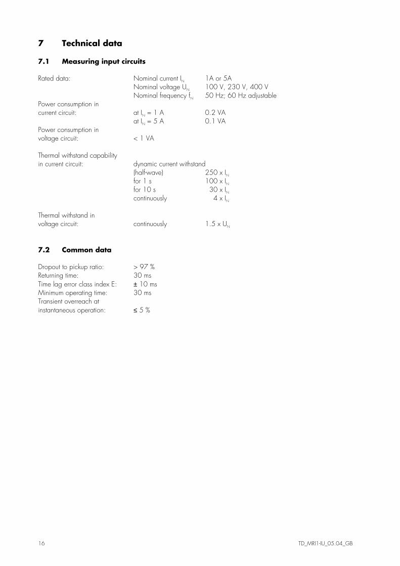
7 Technical data 7.1 Measuring input circuits Rated data: Nominal current IN 1A or 5A Nominal voltage UN 100 V, 230 V, 400 V Nominal frequency fN 50 Hz; 60 Hz adjustable Power consumption in current circuit: at IN = 1 A 0.2 VA at IN = 5 A 0.1 VA Power consumption in voltage circuit: < 1 VA Thermal withstand capability in current circuit: dynamic current withstand (half-wave) 250 x IN for 1 s 100 x IN for 10 s 30 x IN continuously 4 x IN Thermal withstand in voltage circuit: continuously 1.5 x UN 7.2 Common data Dropout to pickup ratio: > 97 % Returning time: 30 ms Time lag error class index E: ± 10 ms Minimum operating time: 30 ms Transient overreach at instantaneous operation: ≤ 5 %

TD_MRI1-IU_05.04_GB 17
7.3 Setting ranges and steps 7.3.1 Definite time overcurrent protection relay Setting range Step Tolerance ISN; ISL tI>
0.2...4.0 x IN 0.03 - 260 s
0.05; 0.1 x IN 0.01; 0.02; 0.05; 0.1; 0.2; 0.5; 1.0; 2.0; 5.0 s
±3 % from set value or min. ±1 % In ±3 % or ±10 ms
I>>N I>>L tI>>
1...40 x IN 0.03...2 s
0.1; 0.2; 0.5; 1.0 x IN 0.01 s; 0.02 s; 0.05 s
±3 % from set value or min. ±1 % In ±3 % or ±10 ms
U UN = 100 V: 10 - 110 V UN = 230 V: 20 - 250 V UN = 400 V: 40 - 440 V
5 V 10 V 20 V
±5 % from set value
7.3.2 Inverse time overcurrent protection relay According to IEC 255-4 or BS 142
Normal Inverse [ ]tIIs
tI s=
−
>0140 02
1
,,
Very Inverse [ ]tIIs
tI s=
−>135
1
,
Extremely Inverse [ ]tIIs
tI s=
−
>802
1
Where: t = tripping time tI> = time multiplier I = fault current Is = Starting current Setting range Step Tolerance ISN; ISL tI>
0.2...4.0 x IN 0.05 - 10
0.05; 0.1 x IN 0.01; 0.02
±3 % from set value or min. ±1 % In ±5 % for NINV and VINV ±7.5 % for NINV and EINV
I>>N I>>L tI>>
1...40 x IN 0.03...2 s
0.1; 0.2; 0.5; 1.0 x IN 0.01 s; 0.02 s; 0.05 s
±3 % from set value or min. ±1 % In ±3 % or ±10 ms
U UN = 100 V: 10 - 110 V UN = 230 V: 20 - 250 V UN = 400 V: 40 - 440 V
5 V 10 V 20 V
±5 % from set value

18 TD_MRI1-IU_05.04_GB
7.4 Inverse time characteristics
1 2 3 4 5 6 7 8 910 20I/IS
0.1
1
10
100
1000
t[s]
tI>=
3.0
10.08.0
6.0
4.0
2.0
0.05
0.1
0.2
0.3
0.40.50.6
0.81.0
1.4
Figure 7.1: Normal Inverse
1 2 3 4 5 6 7 8 910 20I/IS
0.01
0.1
1
10
100
1000
t[s]
tI>=10.08.06.04.03.02.0
0.05 0.10.20.30.40.50.60.81.01.4
Figure 7.2: Extremely Inverse
1 2 3 4 5 6 7 8 910 20I/IS
0.1
1
10
100
1000
t[s]tI>=
10.08.06.0
4.03.0
2.0
0.05
0.1
0.2
0.30.40.50.60.81.01.4
Figure 7.3: Very Inverse
1 10I/IN
0.01
0.1
1
10
100
t[s]
tI>
I>>
tI>>
260
0.03
1.0 402.0
0.03
I>0.02 4.0
Figure 7.4 Definite time overcurrent relay
7.5 Output contacts Number of relays: dependent on relay type Contacts: 2 change-over contacts for trip relay 1 change-over contact for alarm relays Technical data subject to change without notice!

TD_MRI1-IU_05.04_GB 19
8 Order form
Voltage controlled time overcurrent relay MRI1-
3-phase current I>, I>> Rated current 1 A 5 A
I1 I5
Voltage dependent tripping characteristic Rated voltage 100 V 230 V 400 V
U1 U2 U4
Housing (12TE) 19“-rack Flush mounting
A D
Setting of code jumpers
Code jumper J1 J2 J3
Default setting Actual setting Default setting Actual setting Default setting Actual setting
Plugged no function
Not plugged X X
Assignment of the output relays:
Function Relay 1 Relay 2 Relay 3 Relay 4
Default setting
Actual setting
Default setting
Actual setting
Default setting
Actual setting
Default setting
Actual setting
I> alarm X
I> tripping X
I>> alarm X
I>> tripping X
Assignment of the blocking function: Default setting Actual setting Function Blocking Not blocking Blocking Not blocking I> X I>> X

20 TD_MRI1-IU_05.04_GB
Setting list MRI1 Note ! All settings must be checked at site and should the occasion arise, adjusted to the object/item to be protected. Project: SEG job.-no.: Function group: = Location: + Relay code: - Relay functions: Password: Date: Setting of the parameters
Default Actual
Function Unit settings settings
I>SNormal Low set current at nominal voltage x In 0.2
I>SLow Low set current at low voltage x In 0.2
CHAR I> Tripping characteristics DEFT
tI> Time delay at independent time s 0.03
tI> Time multiflier at dependent time characteristics
tI> Reset Reset Modus for dependent time characteristics
I>>SNormal High set current at nominal voltage x In 1.0
I>>SLow High set current at low voltage x In 1.0
tI>> Time delay s 0.03
U Threshold value for undervoltage setting V 10V/20V/40V *
Rated frequency Hz 50
RS Slave address 1
All settings must be checked at site and should the occarision arise, adjusted to the object/item to be protected. * thresholds dependent on rated voltage 100 V / 230 V / 400 V

TD_MRI1-IU_05.04_GB 21

Woodward
Woodward Kempen GmbH Krefelder Weg 47 D – 47906 Kempen (Germany)
Postfach 10 07 55 (P.O.Box) D – 47884 Kempen (Germany) Phone: +49 (0) 21 52 145 1
Internet
www.woodward.com
Sales Phone: +49 (0) 21 52 145 216 or 342 Telefax: +49 (0) 21 52 145 354
e-mail: [email protected]
Service Phone: +49 (0) 21 52 145 614 Telefax: +49 (0) 21 52 145 455
e-mail: [email protected]