ms-cip user manual - imu | inertial measurement unit · 3.3 imu configuration 1. overview imu...
TRANSCRIPT

Copyright © 2019 Memsense, LLC
USER MANUAL
DOC00464 REVISION C

Rev C DOC00464 2
CONTENTS Contents 2
1.0 Overview .............................................................................................................................................. 3
2.0 Installation ........................................................................................................................................... 3
2.1 System Requirements ...................................................................................................................... 3 2.2 Installation........................................................................................................................................ 3
3.0 Application Operation.......................................................................................................................... 4
3.1 Quick Start ........................................................................................................................................ 4 3.2 Data Collection & Visualization ........................................................................................................ 6 3.3 IMU Configuration ............................................................................................................................ 8 3.4 Sample Information........................................................................................................................ 10 3.5 IMU Information ............................................................................................................................ 10 3.6 TimeStamp ..................................................................................................................................... 11
Revision History ........................................................................................................................................ 12

Rev C DOC00464 3
1.0 OVERVIEW
The Memsense Communication Interface Protocol Evaluation Software (MS-CIP Eval SW) is
implemented as a simple application to allow customers to rapidly connect to, configure and
collect data from a Memsense Inertial Measurement Unit (IMU). The software supports the MS-
IMU3020, MS-IMU3030, and the MS-IMU3050.
2.0 INSTALLATION
2.1 SYSTEM REQUIREMENTS
The MS-CIP Evaluation Software requirements are included in the table below.
System Parameter Requirement
Operating System Windows 7 (.NET 4.5 or later) or newer
Minimum Graphics Resolution 1024 x 768
Graphics Device DirectX 9 with WDDM 1.0 or higher driver
Minimum RAM 1 GB
USB Port 1 port available
2.2 INSTALLATION
The MS-CIP Evaluation Software can be downloaded by going to the Memsense website and
selecting the Software tab under any of the MS-IMU3020, MS-IMU3030, or MS-IU3050 product
pages. Once at the Software tab, click the MS-CIP Evaluation Application Download option.
Simply follow the installation instructions provided in the installer.
Rev C DOC00464 4
3.0 APPLICATION OPERATION
3.1 QUICK START
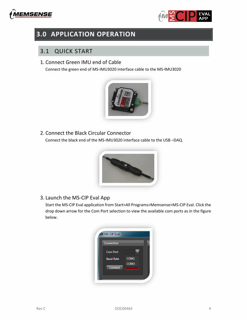
1. Connect Green IMU end of Cable Connect the green end of MS-IMU3020 interface cable to the MS-IMU3020
2. Connect the Black Circular Connector Connect the black end of the MS-IMU3020 interface cable to the USB –DAQ.
3. Launch the MS-CIP Eval App Start the MS-CIP Eval application from Start>All Programs>Memsense>MS-CIP Eval. Click the
drop down arrow for the Com Port selection to view the available com ports as in the figure
below.
Rev C DOC00464 5
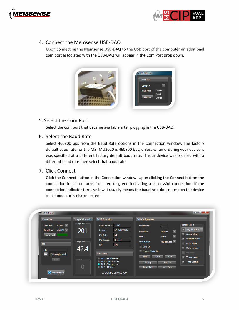
4. Connect the Memsense USB-DAQ Upon connecting the Memsense USB-DAQ to the USB port of the computer an additional
com port associated with the USB-DAQ will appear in the Com Port drop down.
5. Select the Com Port Select the com port that became available after plugging in the USB-DAQ.
6. Select the Baud Rate Select 460800 bps from the Baud Rate options in the Connection window. The factory
default baud rate for the MS-IMU3020 is 460800 bps, unless when ordering your device it
was specified at a different factory default baud rate. If your device was ordered with a
different baud rate then select that baud rate.
7. Click Connect Click the Connect button in the Connection window. Upon clicking the Connect button the
connection indicator turns from red to green indicating a successful connection. If the
connection indicator turns yellow it usually means the baud rate doesn’t match the device
or a connector is disconnected.

Rev C DOC00464 6
3.2 DATA COLLECTION & VISUALIZATION
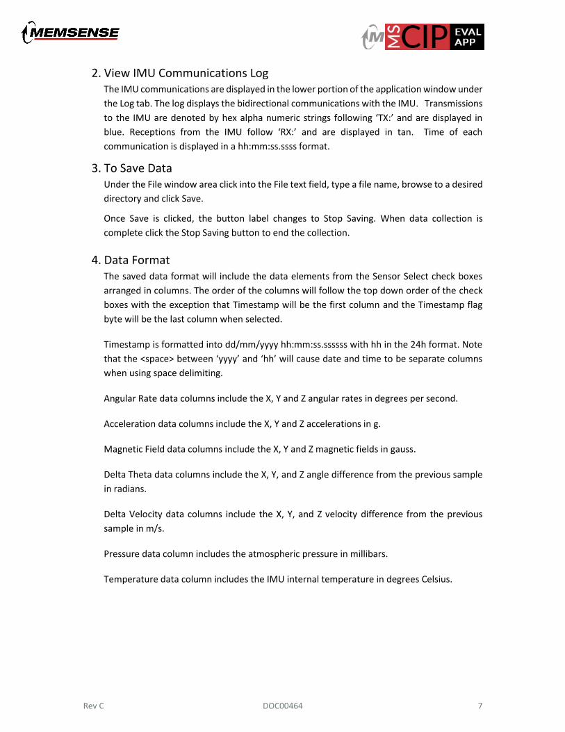
1. View Data Output Plots The inertial sensor outputs are displayed in the lower portion of the application window
under the plots tab. The plots provide a quick visual feedback of the IMU’s operational status.
The plots include gyros with an angular rate displayed in degrees per second, accelerometers
in g, and magnetometers in gauss. The inertial data is plotted at one-tenth of the IMU
configured output sample rate.
When any of the three sensor types plotted are deselected under IMU Configuration the
corresponding plot will be removed from the display. This does not remove the sensor type
from the IMU output until the write button is clicked.
Rev C DOC00464 7
2. View IMU Communications Log The IMU communications are displayed in the lower portion of the application window under
the Log tab. The log displays the bidirectional communications with the IMU. Transmissions
to the IMU are denoted by hex alpha numeric strings following ‘TX:’ and are displayed in
blue. Receptions from the IMU follow ‘RX:’ and are displayed in tan. Time of each
communication is displayed in a hh:mm:ss.ssss format.
3. To Save Data Under the File window area click into the File text field, type a file name, browse to a desired
directory and click Save.
Once Save is clicked, the button label changes to Stop Saving. When data collection is
complete click the Stop Saving button to end the collection.
4. Data Format The saved data format will include the data elements from the Sensor Select check boxes
arranged in columns. The order of the columns will follow the top down order of the check
boxes with the exception that Timestamp will be the first column and the Timestamp flag
byte will be the last column when selected.
Timestamp is formatted into dd/mm/yyyy hh:mm:ss.ssssss with hh in the 24h format. Note
that the <space> between ‘yyyy’ and ‘hh’ will cause date and time to be separate columns
when using space delimiting.
Angular Rate data columns include the X, Y and Z angular rates in degrees per second.
Acceleration data columns include the X, Y and Z accelerations in g.
Magnetic Field data columns include the X, Y and Z magnetic fields in gauss.
Delta Theta data columns include the X, Y, and Z angle difference from the previous sample
in radians.
Delta Velocity data columns include the X, Y, and Z velocity difference from the previous
sample in m/s.
Pressure data column includes the atmospheric pressure in millibars.
Temperature data column includes the IMU internal temperature in degrees Celsius.
Rev C DOC00464 8
3.3 IMU CONFIGURATION
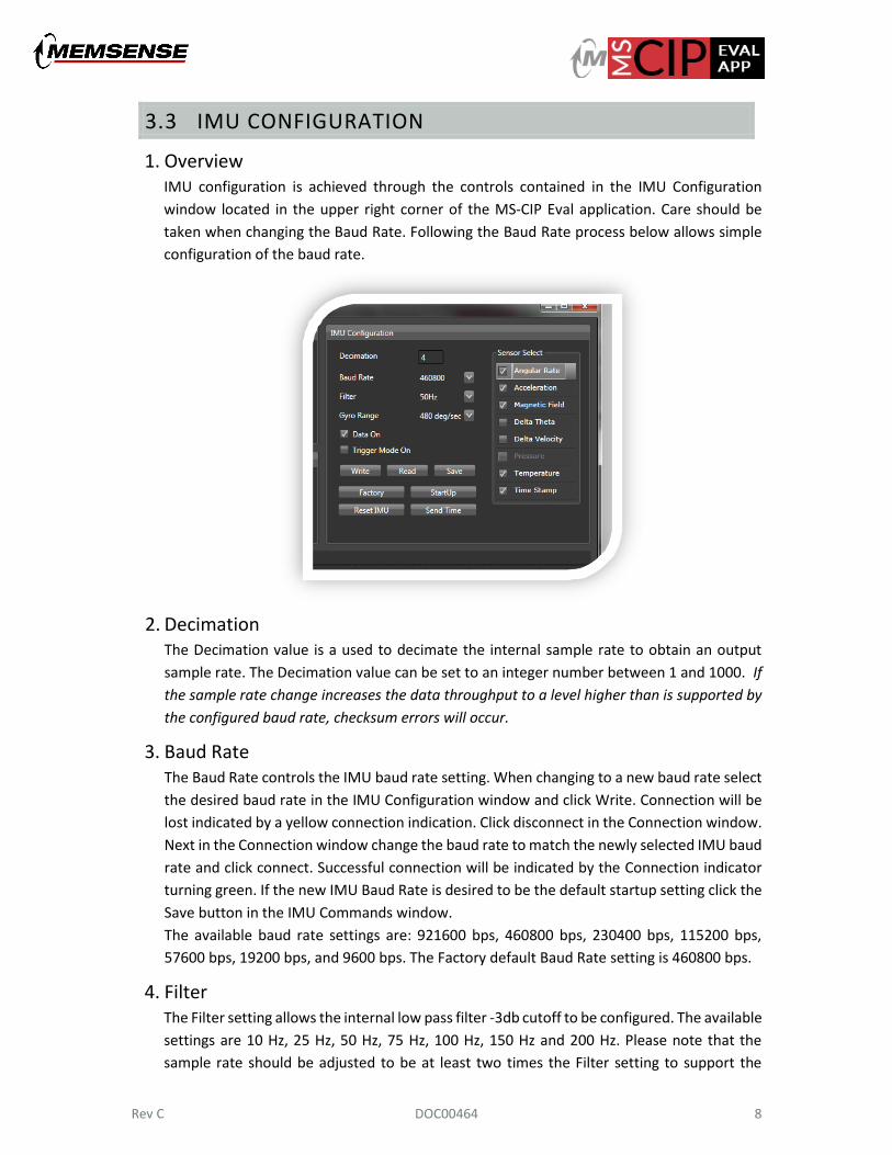
1. Overview IMU configuration is achieved through the controls contained in the IMU Configuration
window located in the upper right corner of the MS-CIP Eval application. Care should be
taken when changing the Baud Rate. Following the Baud Rate process below allows simple
configuration of the baud rate.
2. Decimation The Decimation value is a used to decimate the internal sample rate to obtain an output
sample rate. The Decimation value can be set to an integer number between 1 and 1000. If
the sample rate change increases the data throughput to a level higher than is supported by
the configured baud rate, checksum errors will occur.
3. Baud Rate The Baud Rate controls the IMU baud rate setting. When changing to a new baud rate select
the desired baud rate in the IMU Configuration window and click Write. Connection will be
lost indicated by a yellow connection indication. Click disconnect in the Connection window.
Next in the Connection window change the baud rate to match the newly selected IMU baud
rate and click connect. Successful connection will be indicated by the Connection indicator
turning green. If the new IMU Baud Rate is desired to be the default startup setting click the
Save button in the IMU Commands window.
The available baud rate settings are: 921600 bps, 460800 bps, 230400 bps, 115200 bps,
57600 bps, 19200 bps, and 9600 bps. The Factory default Baud Rate setting is 460800 bps.
4. Filter The Filter setting allows the internal low pass filter -3db cutoff to be configured. The available
settings are 10 Hz, 25 Hz, 50 Hz, 75 Hz, 100 Hz, 150 Hz and 200 Hz. Please note that the
sample rate should be adjusted to be at least two times the Filter setting to support the

Rev C DOC00464 9
Nyquist sampling theorem. The table below provides the decimation for the lowest sample
rate associated with each bandwidth.
Filter Cutoff (Hz)
Sample Rate (sps) Decimation
10 20 40
25 50 16
50 100 8
75 160 5
100 200 4
150 400 2
200 400 2
5. Gyro Range The Gyro Range drop down allows the setting of the gyro’s maximum dynamic range. Click
the down arrow and select the dynamic range desired then click the write button. If the range
selected is desired as a startup range then click the Save button. The gyro dynamic range
options vary by IMU model.
6. Data On The Data On check box allows data outputs to be enabled and disabled.
7. Write The Write button writes the settings contained in the IMU Commands window to the
connected IMU.
8. Read The Read button requests the current settings from the connected IMU.
9. Save The Save button saves the IMU’s current settings as startup settings.
10. Factory The Factory button reads the factory default settings from the connected IMU.
11. Startup The Startup button reads the startup default settings from the connected IMU.
12. Sensor Select Sensor Select options are listed on the right side of the IMU Commands window and allow
the user to configure which sensor measurements are to be included in the IMU out data.
After selecting or deselecting measurements clicking Write configures the IMU and clicking
Save sets the configuration as the default startup configuration.
13. Trigger Mode On When Trigger Mode On is selected and a write performed the external trigger input initiates
a sample. If there is no trigger pulse on the input then the IMU will stop sampling. See the
IMU user manual for input requirements.

Rev C DOC00464 10
3.4 SAMPLE INFORMATION
1. Sample Rate The number of samples per second that are collected from the IMU.
2. Temperature The IMU temperature in degrees Celsius.
3. Pressure The atmospheric pressure in millibar. If the model number of the IMU doesn’t include
pressure or the Sensor Select command has been used to deselect pressure measurements
the pressure display will read 0 and be greyed out.
3.5 IMU INFORMATION
1. Serial Number The unique serial number of the IMU.
2. Product The product model.
3. Cal Date The date at which the IMU calibration was programmed.
4. FW Version The version of the firmware programmed on the IMU.
5. ISR The internal sample rate of the IMU in samples per second.

Rev C DOC00464 11
3.6 TIMESTAMP
1. Bit 0 – PPS Received Set to indicate GPS 1 PPS received.
2. Bit 1 – Time was Set Set to indicate GPS Time was set.
3. Bit 2 – Time not Set No GPS Time Set, Using GPS Week 0 and Time 0
4. Bit 3 – PPS Lost No 1 PPS received
5. Timestamp Display Displays the Timestamp starting from GPS Week 0 and Time 0 if no GPS time is set. When
the GPS time was set then the Timestamp increments from the set time. Time adjustments
are performed when GPS time is set and 1 PPS is received.

Rev C DOC00464 12
REVISION HISTORY
REV STATUS DESCRIPTION DATE
A Obsolete Initial Release 3-4-2016
B Obsolete Updated plot functionality
Added Timestamp Flag byte description to Data Format
Updated Delta Theta and Velocity descriptions.
Updated pressure display details
Added External Trigger Description
Added Timestamp section.
6-24-2016
C Released Corrected error relative to IMUs supported. 4-3-2019