msd41 pump repair manual - maruyama
TRANSCRIPT

MSD41 Pump
Repair Manual
PDF created with pdfFactory Pro trial version www.pdffactory.com

Remove the six 6mm Allen head screws retaining Manifold B.
1
2
3
4
5
6
PDF created with pdfFactory Pro trial version www.pdffactory.com

Remove Manifold B from the Cylinders. Sometimes the adapter with stay in cylinder and other times it will remain in Manifold B. Either way it will have removed for further disassembly. Use caution here so not to cause any damage to either component.
Adapter
PDF created with pdfFactory Pro trial version www.pdffactory.com

If adapter stays in Manifold B and proves be difficult to remove , You may use a flat bladed screw driver to gently pry it from the manifold. There will always be a small gap between the adapter and Manifold B. Use caution not to damage either component.
If adapter stays in cylinder and can not be removed by simply twisting them apart with your hands you may need to carefully try holding cylinder with your hands and twisting adapter with some pliers. Use caution to stay on the larger boss of the adapter or you will damage the adapter and it will have to be replaced.
PDF created with pdfFactory Pro trial version www.pdffactory.com

Remove the valve stack from Manifold B.
Remove the cylinders from piston rods by sliding them forward.
PDF created with pdfFactory Pro trial version www.pdffactory.com

Now that you have cylinders removed from the rods. Look at the components closely . Take note how the parts are orientated for future reference.
Remove the 10mm nut retaining the Piston packing and associated items.
PDF created with pdfFactory Pro trial version www.pdffactory.com

Lay out the components in order as you remove them so you will know how to reassemble them. The Square cut edge of the piston always goes toward the Manifold B .
Manifold B
Rounded Edge Square Cut Edge
PDF created with pdfFactory Pro trial version www.pdffactory.com

Manifold BClean Manifold B , make sure there is no corrosion present. Inspect the sealing surfaces for wear and flaws. Lightly lubricate sealing surfaces that will be receiving O-rings.
Lubricate with light weight oil
Install Valve sack into Manifold B
PDF created with pdfFactory Pro trial version www.pdffactory.com

Install the three springs into the valve sacks.
PDF created with pdfFactory Pro trial version www.pdffactory.com

Install the three valves over the springs. The valves form a bowl shape which centers the spring.
Correct Orientation
PDF created with pdfFactory Pro trial version www.pdffactory.com

Lubricate and Install new O-rings on to each adapter. Gently push adapter into the Manifold B, This will keep the valve stacks in place. Always use new O-rings .
PDF created with pdfFactory Pro trial version www.pdffactory.com
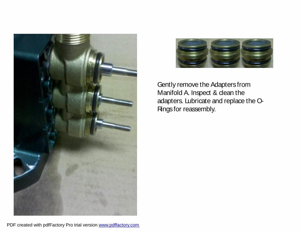
Gently remove the Adapters from Manifold A. Inspect & clean the adapters. Lubricate and replace the O-Rings for reassembly.
PDF created with pdfFactory Pro trial version www.pdffactory.com
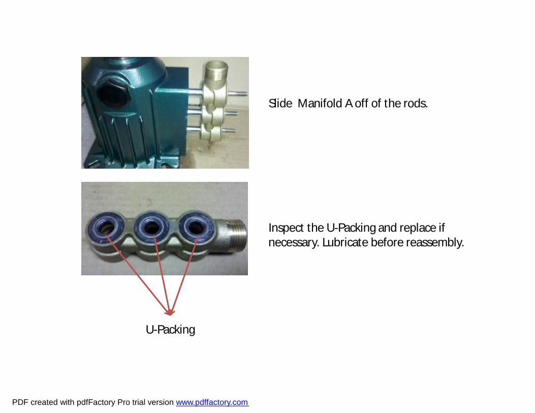
Slide Manifold A off of the rods.
Inspect the U-Packing and replace if necessary. Lubricate before reassembly.
U-Packing
PDF created with pdfFactory Pro trial version www.pdffactory.com

Install Manifiold A on the rods. Remove the old O-rings and replace with new lubricated O-rings. Slide adapters into Manifold A.
PDF created with pdfFactory Pro trial version www.pdffactory.com

Inlet Valve Seat
Piston Packing
Spacer
Piston Retainer
Spring Washer
Nut
Install the inlet valve seat and spacer onto the piston rod.
Lubricate the piston packing with light oil and slide it over the spacer. The square cut edge goes toward manifold B.
Now install the Piston Retainer, Spring Washer, and Nut. Finally tighten the nuts down.
PDF created with pdfFactory Pro trial version www.pdffactory.com

Lubricate the Cylinders and slide them over the Piston Packing. Use your fingers to compress the Piston Packing to start it into the cylinder. Never use any sharp object to do this as it will damage the Piston Packing.
PDF created with pdfFactory Pro trial version www.pdffactory.com

Slide Manifold B on to the cylinders. Then Install the six 6mm Allen head screws with a small amount of Loctite on each bolt.
1
5
4
3
6
2
Run all six bolts down to eliminate the slack between the bolts and the Manifold. Using the pattern in the picture you are going to slowly tighten the bolts to pull the manifold down evenly. This may take two or three times before the bolts are completely tight.
PDF created with pdfFactory Pro trial version www.pdffactory.com