mse retaining wall design considerations by … retaining wall design considerations by marcus...
TRANSCRIPT

MSE Retaining Wall Design Considerations
by
Marcus Galvan, P.E. TxDOT Bridge Division
Geotechnical Branch

Wall Selection MSE
CONCRETE BLOCK
TEMPORARY EARTH
SPREAD FOOTING
Gabions
Drilled Shaft
Tiedback
Soil Nail
Hybrid Walls – MSE/Soil Nail
RETAINING WALL
SELECTION
FILL SITUATIONS
CUT SITUATIONS
CUT/FILL SITUATIONS
DRILLED SHAFT
TIEDBACK SOIL NAIL
MSE WITH SHORING SPREAD FOOTING
WITH SHORING
DRILLED SHAFT MSE WITH SHORING SPREAD FOOTING
WITH SHORING HYBRID – SOIL NAIL/MSE
MSE CONCRETE BLOCK SPREAD FOOTING
TEMPORARY EARTH GABION

Wall Usage by TxDOT (August 2010 through September 2011)
Retaining Wall By Type
72%
1%
12%
3%5%
2% 4% 1%
MSE Conc. Block CIP SN RN DS TB other

Wall Usage by TxDOT (August 2010 through September 2011)
Wall Type Area (ft2) % MSE 3,196,417 72 Concrete block (no r/f) 47,791 1 Cantilever drilled shaft 72,286 2 Soil Nailed 146,793 3 Rock Nailed 197,216 5 Tied-back 161,827 4 Spread footing 505,019 12 Other 22,389 1
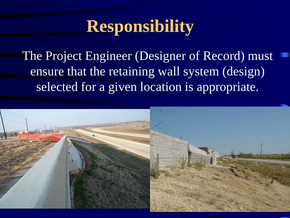
Responsibility The Project Engineer (Designer of Record) must
ensure that the retaining wall system (design) selected for a given location is appropriate.

MSEW Construction Project Development
• External Stability Check by TXDOT or Consultant – Sliding – Limiting Eccentricity – Bearing Capacity – Global Stability – Settlement
• Internal Stability Check by Vendor
– Tensile Resistance – Pullout Resistance – Face Element – Face Element Connection
• MSEW reinforcement and wall type is NOT specified at
project bidding stage

MSEW Construction Project Development
• External Stability Check by TXDOT or Consultant – Sliding – FS > 1.5 – Limiting Eccentricity – e < B/6 – Bearing Capacity – FS > 2.0 – Global Stability – FS > 1.3 – Settlement

Assumed Soil Parameters (External Analysis)
Material Short- term Long-term
c (psf) φ (ο) c (psf) φ (ο)
Reinforced fill
Type A,B,D 0 34 0 34
Type C 0 30 0 30
Retained backfill
controlled fill, PI<30 750 0 0
30 or PI- correlation
Foundation soil (Fill)
controlled fill, PI<30 750 0 0
30 or PI- correlation

Principal Modes of Failure - External

Principal Modes of Failure - External
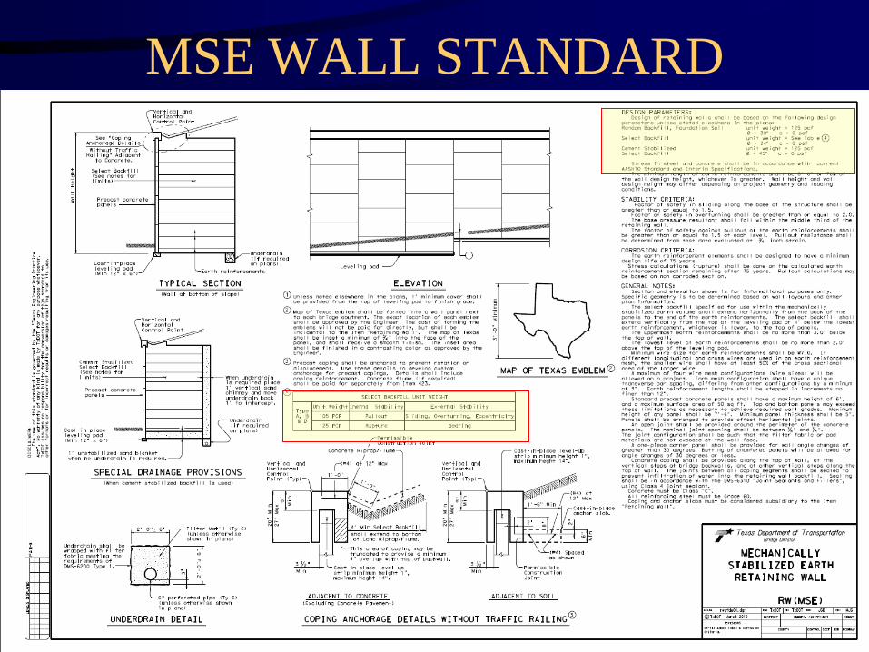
MSE WALL STANDARD

External Stability - Sliding
FS – Sliding = V1(Tan (phi)) F1 + F2
105/125 = 0.84 or a 16% reduction in sliding resistance

Sliding Analysis

Sliding Analysis
But less than 2.04
or 0.84 H

Sliding Analysis
But less than 2.04
or 0.87 H
We find that the sliding analysis is very sensitive to the unit weight in both the resisting and driving zones and to the coefficient of friction utilized at the base of the wall.

Principal Modes of Failure - External

Soil Characteristics
• Stability of every wall must be evaluated • Short-term and Long-term conditions (make
sure that the soil strengths used in analysis are valid for the given soil profile).

Soil Characteristics If the site investigation and geotechnical analysis
results in design parameters that are different from those shown on the RW(MSE) standard, minimum factors of safety for the principle external modes of failure and a ground improvement strategy is not employed that would improve strength values to meet or exceed design parameters shown on the standard, the design strengths must be communicated to the wall supplier. This can be accomplished by plan note or a modified standard reflecting lower strengths as applicable.

DETERMINATION OF THE UNDRAINED SHEAR STRENGTH
OF FINE GRAINED SOILS Short Term Analysis
• TEXAS CONE PENETROMETER
• UNDRAINED TRIAXIAL TESTING
• IN-SITU VANE SHEAR TESTING
• DIRECT SHEAR TESTING

Texas Cone Penetrometer - TCP
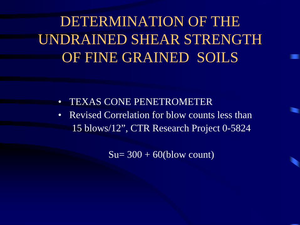
DETERMINATION OF THE UNDRAINED SHEAR STRENGTH
OF FINE GRAINED SOILS
• TEXAS CONE PENETROMETER • Revised Correlation for blow counts less than
15 blows/12”, CTR Research Project 0-5824
Su= 300 + 60(blow count)
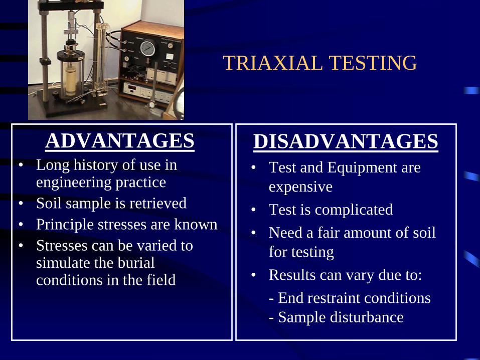
TRIAXIAL TESTING
ADVANTAGES • Long history of use in
engineering practice • Soil sample is retrieved • Principle stresses are known • Stresses can be varied to
simulate the burial conditions in the field
DISADVANTAGES • Test and Equipment are
expensive • Test is complicated • Need a fair amount of soil
for testing • Results can vary due to: - End restraint conditions
- Sample disturbance

IN-SITU VANE SHEAR TESTING
ADVANTAGES • Rapid, simple, and inexpensive test • Long history of use in engineering
practice • Reproducible results in
homogeneous fine grained soils • Minimal soil disturbance • Yields the peak and residual
undrained shear strength of fine grained soils
DISADVANTAGES • No sample is recovered • Limited to soft to medium stiff fine
grained soils • Results can be affected by roots,
shells, gravel, sand seams, and lenses

SHORT TERM GLOBAL STABILITY ANAYLYS BASED ON APPROPRIATE
SHEAR STRENGTH
C = 2000 psf, φ = 0o
C = 1200 psf, φ = 0o C = 1000 psf, φ = 0o
C = 750 psf,
φ = 0o
C = 2000 psf,
φ = 34o
FS = 1.45
DETERMINATION OF THE DRAINED SHEAR STRENGTH
OF FINE GRAINED SOILS Long Term Analysis
• Consolidated Undrained TRIAXIAL Test
with Pore Pressure measurements. • P.I. Correlation

CU TRIAXIAL TESTING
ADVANTAGES • Long history of use in
engineering practice • Soil sample is retrieved • Principle stresses are known • Stresses can be varied to
simulate the burial conditions in the field
DISADVANTAGES • Test and Equipment are
expensive • Test is complicated • Testing Takes Time. • Need a fair amount of soil
for testing • Results can vary due to: - End restraint conditions
- Sample disturbance

CU Triaxial Test Results
Cohesion Intercept = 2.3 psi (330 psf)
Phi = 29 degrees

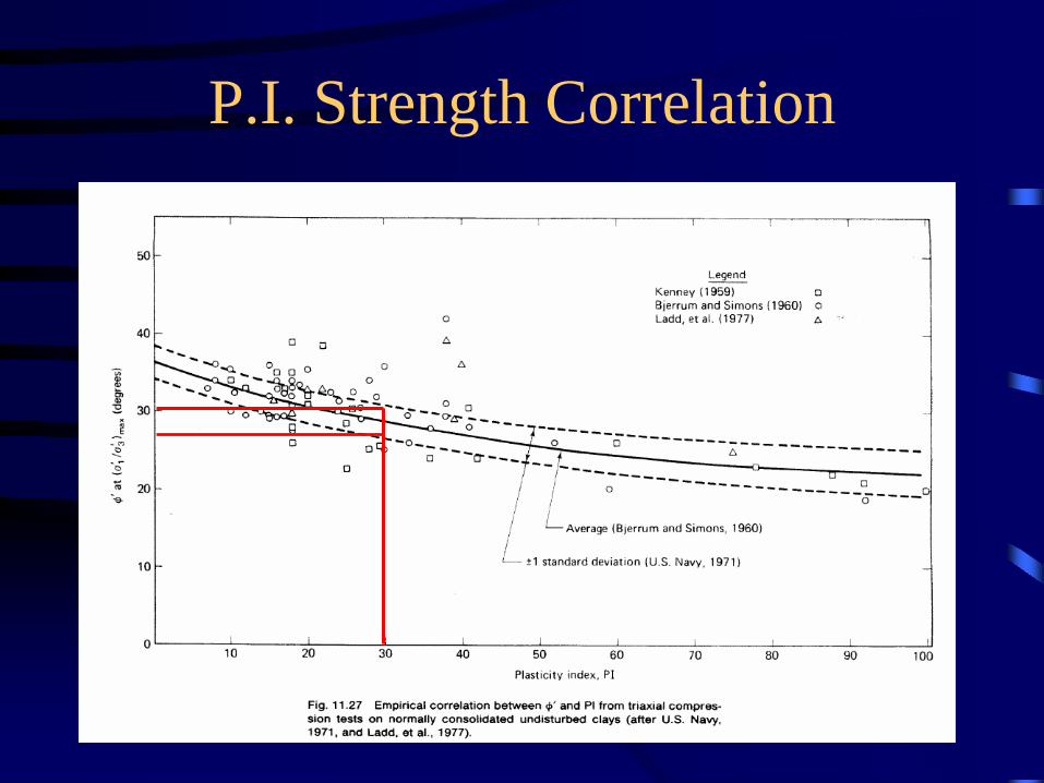
P.I. Strength Correlation
• ADVANTAGES • Quick • History of use in
engineering practice • Various studies have
contributed to the correlation charts.
DISADVANTAGES • Correlation, does not take
into account secondary structure of materials.
• Indirect measure of soil shear strength.
• Uncertainty in correlation. • Cohesive component is
unknown.
P.I. Strength Correlation

Long Term GLOBAL STABILITY ANAYLYS BASED ON APPROPRIATE
SHEAR STRENGTH
C = 2200 psf, φ = 0o
C = 70 psf, φ = 30o C = 60 psf, φ = 29o
C = 50 psf,
φ = 30o
C = 2000 psf,
φ = 34o
FS = 1.35

Principal Modes of Failure - External

POOR PREPARATION OF RETAINING WALL FOUNDATION SOILS
OTHER CONSIDERATIONS

MSE Wall W/Fill
and Ground Improvement

Foundation Settlement
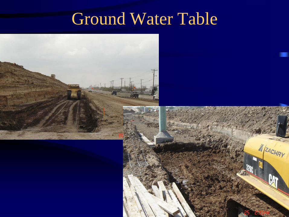
Ground Water Table
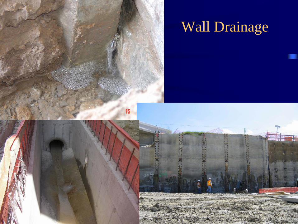
Wall Drainage

Special Design Considerations
• Ground Improvement – Remove and Replace – Stone Columns – Rammed Aggregate Piers

Pile Supported Embankment
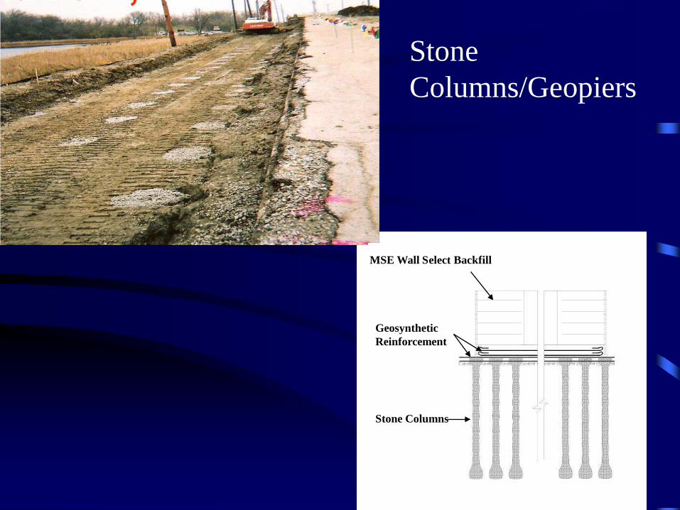
Stone Columns
MSE Wall Select Backfill
Geosynthetic Reinforcement
Stone Columns/Geopiers

Remove and Replace/Wick Drains

Remove and Replace – Reinforced Pad

CONCLUSIONS • TxDOT has designed and constructed numerous MSE retaining
walls.
• In spite of the increased usage, TxDOT has had relatively few retaining wall failures.
• The design and planning phase of retaining walls is critical and must address the actual site conditions, including soil and loading, that the wall will be subjected to.
• If values in the analysis of the wall (i.e. friction angle for both the retained and foundation soils) are less than that shown on the RW(MSE) standard and do not result in a ground improvement that would positively impact these values, the designer of record should include the soil strength information in the plan set for use by the wall supplier.

QUESTIONS?

Ground Conditions
• Soil Shear Strength – Short Term, C and phi – Long Term, C’ and phi’
• Ground Water Table • Necessary Fill • Necessary Cut

MSE Principal Modes of Failure

LOSS OF MSE BACKFILL

LOSS OF MSE BACKFILL
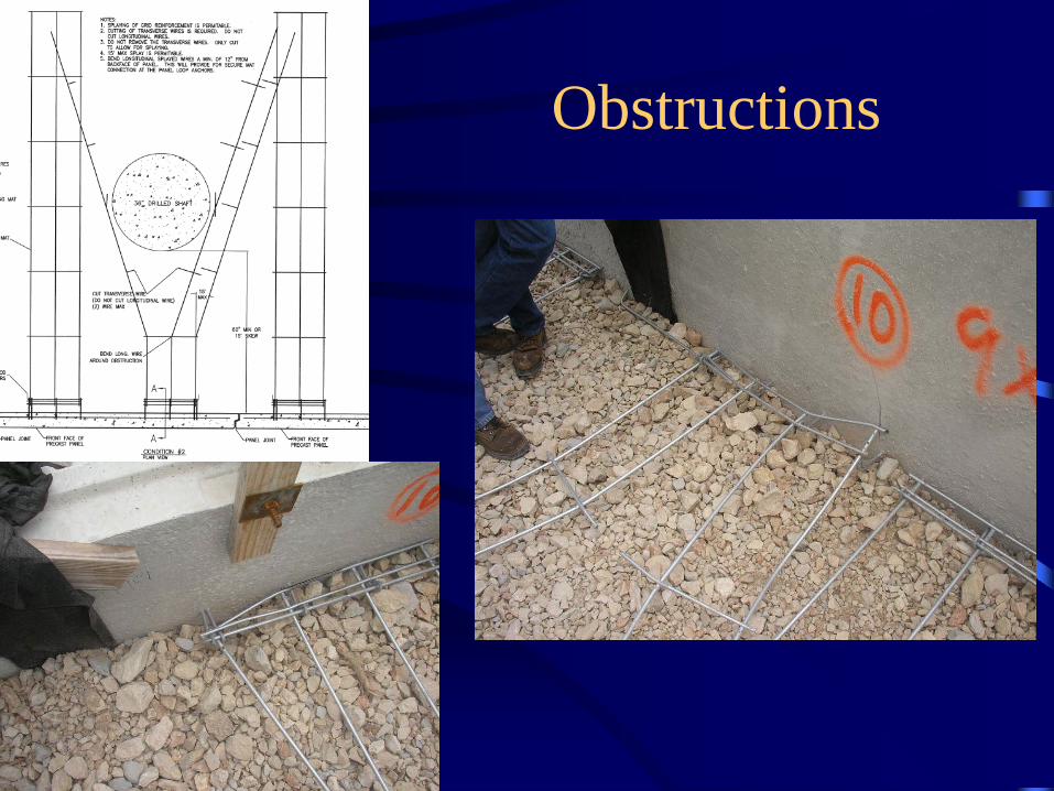
Obstructions

Obstructions
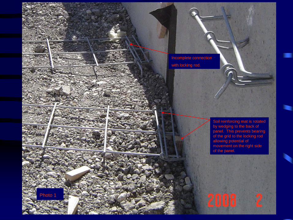
Incomplete connection
with locking rod.
Soil reinforcing mat is rotated by wedging to the back of panel. This prevents bearing of the grid to the locking rod allowing potential of movement on the right side of the panel.
Photo 1

Obstructions

Omitted Reinforcement

P.I. Strength Correlation

Design Considerations vs
Special Design Considerations
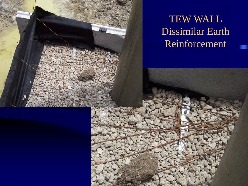
TEW WALL Dissimilar Earth Reinforcement
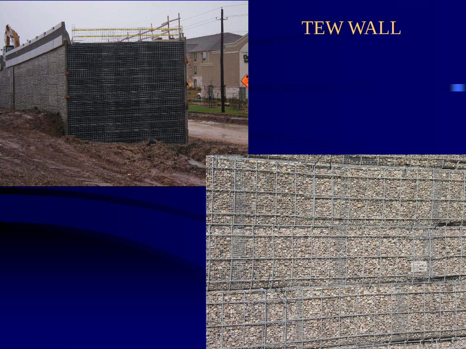
TEW WALL