msg3 revision 2005.1
DESCRIPTION
msg3TRANSCRIPT
ATA MSG-3
Copyright © 2005-2006 Air Transport Association of America, Inc. All rights reserved. Output Page: 1
A TA MSG-3 Information
Quick Access(1)
ATA MSG-3
Operator/ManufacturerScheduled Maintenance Development
Revision 2005.1
Air Transport Association of America, Inc.1301 Pennsylvania Avenue, NW - Suite 1100
Washington, DC 20004-1707USA
Copyright © 2005-2006 Air Transport Association of America, Inc. All rights reserved. No part of this document may bereproduced or transmitted by any means, electronic or mechanical, including photocopying and recording, or by anyinformation storage or retrieval system, except as may be expressly permitted in writing by the publisher.

ATA MSG-3
Copyright © 2005-2006 Air Transport Association of America, Inc. All rights reserved. Output Page: 2
Important Information About This Document
Read Before Using This Document
This document contains recommended specifications that have been developed for the covered topics. ATA does notmandate their use. You must decide whether or not to use the recommendations in this document. You may choose to usethem in whole, in part, or not at all.
There may be practices, standards and/or regulatory requirements applicable to your operations that exceed therecommendations in this document. You are solely responsible for determining if such practices, standards or requirementsexist and whether they apply to your activities, and for complying with those that are applicable. Such practices, standardsand requirements can change significantly over time.
ATA does not guarantee, promise or warrant that the specifications in this document will meet the needs of your operations.This is a determination that you must make and for which ATA is not responsible.
For Additional Information
For more information or to order additional publications, refer to the ATA Publications Catalog, the Web site atwww.airlines.org, e-mail [email protected]., or call the ATA Distribution Center at:
800-497-3326 (U.S. and Canada)301-490-7951
For Technical Information and Change Submissions
Errata information for ATA Publications is available at the ATA Publications Web page.
For technical information or to recommend an alteration or amendment to this specification, please submit therecommendation and any supporting documentation to ATA:
E-mail: [email protected]: 202-626-4062Fax: 202-626-4181

ATA MSG-3
Copyright © 2005-2006 Air Transport Association of America, Inc. All rights reserved. Output Page: 3
Transmittal Letters

ATA MSG-3
Copyright © 2005-2006 Air Transport Association of America, Inc. All rights reserved. Output Page: 4

ATA MSG-3
Copyright © 2005-2006 Air Transport Association of America, Inc. All rights reserved. Output Page: 5
Highlights
Prepared By:
Maintenance Steering Group - 3 Task Force
Air Transport Association of America
Release History
Revision 2005.1 (March, 2005)
Revision 2003.1 (March, 2003)
Revision 2002.1 (March, 2002)
Revision 2001.1 (February, 2001)
Revision 2000.1 (March 2000, reformatted into an electronic document)
Revision 2 (September 12, 1993)
Revision 1 (March 31, 1988)
Original Issue (September 30, 1980)
Revision 2005.1 (Revised March, 2005)
Location Description of Change
All See the Preface section for a complete description.
ATA MSG-3
Copyright © 2005-2006 Air Transport Association of America, Inc. All rights reserved. Output Page: 6
Preface
Airline and manufacturer experience in developing scheduled maintenance for new aircraft has shown that more efficientprograms can be developed through the use of logical decision processes.
In July, 1968, representatives of various airlines developed Handbook MSG-1, "Maintenance Evaluation and ProgramDevelopment," which included decision logic and inter-airline/manufacturer procedures for developing scheduledmaintenance for the new Boeing 747 aircraft.
Subsequently, it was decided that experience gained on this project should be applied to update the decision logic and todelete certain 747 detailed procedural information so that a universal document could be made applicable for later new typeaircraft. This was done and resulted in the document, entitled, "Airline/ Manufacturer Maintenance Program PlanningDocument," MSG-2. MSG-2 decision logic was used to develop scheduled maintenance for the aircraft of the 1970's.
In 1979, a decade after the publication of MSG-2, experience and events indicated that an update of MSG procedures wasboth timely and opportune in order for the document to be used to develop maintenance for new aircraft, systems orpowerplants.
An ATA Task Force reviewed MSG-2 and identified various areas that were likely candidates for improvement. Some ofthese areas were the rigor of the decision logic, the clarity of the distinction between economics and safety, and the adequacyof treatment of hidden functional failures. Additionally
A. The development of new generation aircraft provided a focus, as well as motivation, for an evolutionaryadvancement in the development of the MSG concept.
B. New regulations which had an effect on maintenance programs had been adopted and therefore needed to bereflected in MSG procedures. Among those were new damage tolerance rules for structures and the SupplementalStructural Inspection program for high time aircraft.
C. The high price of fuel and the increasing cost of materials created trade-off evaluations which had great influenceson maintenance program development. As a result, maintenance programs required careful analysis to ensure thatonly those tasks were selected which provided genuine retention of the inherent designed level of safety andreliability, or provided economic benefit.
MSG-3, Original Revision
Against this background, ATA airlines decided that a revision to existing MSG-2 procedures was both timely andappropriate. The active participation and combined efforts of the FAA, CAA/UK, AEA, U.S. and European aircraft andengine manufacturers, U.S. and foreign airlines, and the U.S. Navy generated the document, MSG-3. As a result there werea number of differences between MSG-2 and MSG-3, which appeared both in the organization/presentation of the materialand in the detailed procedural content. However, MSG-3 did not constitute a fundamental departure from the previousversion, but was built upon the existing framework of MSG-2 which had been validated by ten years of reliable aircraftoperation using maintenance based thereon.
The following reflects some of the major improvements and enhancements generated by MSG-3 as compared to MSG-2.
1. Systems/Powerplant Treatment:
MSG-3 adjusted the decision logic flow paths to provide a more rational procedure for task definition and a more
ATA MSG-3
Copyright © 2005-2006 Air Transport Association of America, Inc. All rights reserved. Output Page: 7
straightforward and linear progression through the decision logic.
MSG-3 logic took a "from the top down" or consequence of failure approach. At the outset, the functional failurewas assessed for consequence of failure and was assigned one of two basic categories:
A. SAFETY
B. ECONOMIC
Further classification determined sub-categories based on whether the failure was evident to or hidden from theoperating crew. (For structures, category designation was "significant" or "other" structure, and all functionalfailures were considered safety consequence items).
With the consequence category established for systems/powerplants, only those task selection questions pertinent tothe category needed to be asked. This eliminated unnecessary assessments and expedited the analysis. A definiteapplicability and effectiveness criteria was developed to provide more rigorous selection of tasks. In addition, thisapproach helped to eliminate items from the analytical procedure whose failures had no significant consequence.
Task selection questions were arranged in a sequence such that the most preferred, most easily accomplished task,was considered first. In the absence of a positive indication concerning the applicability and effectiveness of a task,the next task in sequence was considered, down to and including possible redesign.
2. Structures Treatment:
Structures logic evolved into a form which more directly assessed the possibility of structural deteriorationprocesses. Considerations of fatigue, corrosion, accidental damage, age exploration and others, were incorporatedinto the logic diagram and were routinely considered.
3. MSG-3 recognized the new damage tolerance rules and the supplemental inspection programs, and provided amethod by which their intent could be adapted to the Maintenance Review Board (MRB) process instead ofrelying on type data certificate restraints. Concepts such as multiple failures, effect of failure on adjacent structure,crack growth from detectable to critical length, and threshold exploration for potential failure, were covered in thedecision logic of the procedural material.
4. The MSG-3 logic was task-oriented and not maintenance process oriented (MSG-2). This eliminated the confusionassociated with the various interpretations of Condition Monitoring (CM), On-Condition (OC), Hardtime (HT)and the difficulties encountered when attempting to determine what maintenance was being accomplished on anitem that carried one of the process labels.
By using the task-oriented concept, one would be able to view the MRB document and see the initial scheduledmaintenance reflected for a given item (e.g., an item might show a lubrication task at the "A" frequency, andinspection/functional check at the "C" frequency and a restoration task at the "D" frequency).
5. Servicing/Lubrication was included as part of the logic diagram to ensure that this important category of task wasconsidered each time an item was analyzed.
6. The selection of maintenance tasks, as output from the decision logic, was enhanced by a clearer and more specificdelineation of the task possibilities contained in the logic.
7. The logic provided a distinct separation between tasks applicable to either hidden or evident functional failures;therefore, treatment of hidden functional failures was more thorough than that of MSG-2.
8. The effect of concurrent or multiple failure was considered. Sequential failure concepts were used as part of thehidden functional failure assessment (Systems/Powerplant), and multiple failure was considered in structuralevaluation (Structures).

ATA MSG-3
Copyright © 2005-2006 Air Transport Association of America, Inc. All rights reserved. Output Page: 8
9. There was a clear separation between tasks that were economically desirable and those that were required for safeoperation.
10. The structures decision logic no longer contained a specific numerical rating system. The responsibility fordeveloping rating systems was assigned to the appropriate manufacturer with approval of the Industry SteeringCommittee.
MSG-3, Revision 1
In 1987, after using MSG-3 procedures on a number of new aircraft and powerplants in the first half of the 1980's, it wasdecided that the benefits of the experience so gained should be used to improve the document for future application; thus,Revision 1 was undertaken.
This revised document includes changes developed by American and European airframe manufacturers, American andEuropean airworthiness authorities, supplemented and agreed to by the Air Transport Association of America and otherairline representatives.
The major improvements and enhancements reflected in items one through nine above were basically unchanged and remainapplicable to this revised document.
The following are some of the more noteworthy revisions that have been incorporated:
1. Table of Contents and a List of Effective Pages: ADDED.
2. Clarification that MSG-3 is used to develop an "initial scheduled maintenance program."
3. The task - "Operating Crew Monitoring": DELETED.
4. Section addressing "Threshold Sample": REVISED.
5. Section addressing "Program Development Administration": DELETED.
6. "Top-down approach" - explanation of process: ADDED.
7. "Visual Check" added to "Operational Check" task.
8. System/Powerplant and Structures logic diagrams: REVISED.
9. Task selection criteria table: ADDED.
10. Inspections:
Detailed Inspection - REVISED.
Directed Inspection - DELETED.
External Surveillance Inspection - DELETED.
General Visual Inspection - REVISED.
Internal Surveillance Inspection - DELETED.
Special Detailed Inspection - UNCHANGED.
Walk Around Check Inspection - DELETED.

ATA MSG-3
Copyright © 2005-2006 Air Transport Association of America, Inc. All rights reserved. Output Page: 9
11. Clarification of hidden functional failure: "one additional failure."
12. Inspection/Functional Check task question revised.
13. Reference to a "User's Guide" for procedures related to administration and forms added.
14. Reference to "off-aircraft" deleted.
15. Operating Crew Normal Duties - "Normal Duties" revised to delete pre-flight and post-flight check list; added "ona daily basis" for frequency of usage with respect to normal crew duties.
16. Added that procedures for handling composite of other new materials may have to be developed.
17. Reference to specific U.S. Federal Air Regulations: DELETED.
18. Definition of "Operating": REVISED.
19. Defined logic for failures which may affect dispatch capability or involve the use of abnormal or emergencyprocedures. Failure-effect Category 6 is now identified as "Operational - Evident".
20. Noted that each MSI and SSI should be recorded for tracking purposes whether or not a task was derivedtherefrom.
MSG-3, Revision 2
In 1993, MSG-3 Revision 2 was incorporated. The most significant changes introduced were:
1. To adapt MSG-3 logic procedures to assure development of tasks/intervals associated with the aircraft's certificatedoperating capabilities.
2. To provide guidelines which ensure that a consistent approach be taken with respect to tasks/intervals required tomaintain compliance with Type Certification requirements.
3. To provide guidelines on the development of Corrosion Prevention and Control Programs.
4. To introduce procedures to determine the appropriate scheduled maintenance requirements for composite structure.
5. To revise inspection task definitions.
MSG-3 [Section 2-4] and its respective logic diagrams have been revised to add an evaluation process to insure theCorrosion Prevention and Control Program (CPCP) is considered in the evaluation of each Structural Significant Item(SSI) and every zone.
Damage Sources [Heading 2-4-3.1] now includes a discussion of non-metallic materials (composites).
Procedures [Heading 2-4-4.1] has been revised to add Procedure and Decision blocks for the CPCP evaluation and edited toproduce a more ordered flow of the Procedure and Decision block numbers.
The Glossary - [Appendix A] Inspection Level Definitions have been revised to apply to Systems, Powerplants andStructures, and definitions related to CPCP have been added.
It is suggested, in order to fully comprehend the MSG-3 concept, that the entire MSG-3 document be reviewed andconsidered prior to accepting or modifying its approaches to maintenance development. A User's Guide or Policies and
ATA MSG-3
Copyright © 2005-2006 Air Transport Association of America, Inc. All rights reserved. Output Page: 10
Procedures Handbook may be adopted with guidance and approval of the Industry Steering Committee.
MSG-3, Revision 2001
In 2001, MSG-3 Revision 2001 was incorporated. The most significant changes introduced were:
1. Added distance requirement and use of a mirror to definition of General Visual Inspection (GVI).
2. Deleted "visual" from definition of Detailed Inspection, and substituted the term "used" for the word "necessary."
3. Corrected terminology throughout the document to change the product of MSG-3 from a "maintenance program" tosimply "maintenance."
4. Guidance was added to [Heading 2-3-5.1]. to cover acceptable assumptions as to the flight crew "normal duties" indetermining whether or not a functional failure is evident.
5. Expanded the wording on hidden functions of safety/emergency systems or equipment [Heading 2-3-5.3].
6. Deletion of the requirement to forward FEC 6 items without task to the ISC/MRB for review..
7. Significantly expanded the wording on "Interval Determination" [Subject 2-3-8].
8. Rewrote [Section 2-5] to incorporate enhanced zonal analysis.
9. Added a section [Section 2-6] on analysis for Lightning/High Intensity Radiated Field (L/HIRF).
10. Added many more terms to the Glossary.
MSG-3, Revision 2002
In 2002, MSG-3 Revision 2002 was incorporated. The most significant changes introduced were:
1. Added wording emphasizing the importance of recording any and all assumptions made during analysis.
2. Added wording emphasizing the importance of fully considering all available Vendor Recommendations duringMWG discussions.
3. Rewrote the MSI Selection Process to expand and clarify.
4. Added a new [Subject 2-3-2], "Analysis Procedure" in order to separate its paragraphs from the MSI SelectionProcess.
5. Procedure added for Fault-Tolerant Systems Analysis.
6. Explanation provided for use of MMEL in answering Systems Analysis Level 1 Question 4.
7. General Visual Inspection (GVI) definition was clarified.
8. Structural Maintenance Task Development expanded to address analysis of non-metallic structures.
9. Glossary additions - "Fault" and "Redundant Functional Elements."
MSG-3, Revision 2003

ATA MSG-3
Copyright © 2005-2006 Air Transport Association of America, Inc. All rights reserved. Output Page: 11
In 2003, MSG-3 Revision 2003 was incorporated. The most significant changes introduced were:
1. Added 3-letter task abbreviations to the 2-letter task abbreviations of [Heading 2-1-2.2]
2. Rewrote the procedural [Subject 2-3-4]. for "Fault-Tolerant Systems"as per FAA request.
3. Added a definition for "Fault-Tolerant System" to the Appendix A, Glossary.
4. Divided existing definition in Appendix A, Glossary, for "Safety/Emergency Systems or Equipment" into bulletpoints to clarify.
MSG-3, Revision 2005
The changes introduced in 2005 were:
1. Added a NOTE in the MSI Selection [Subject 2-3-1]. Step 2 to identify design features that may result indevelopment of ignition sources in the fuel tank system.
2. Corrected [Heading 2-3-5.1] referencing the Airplane Flight Manual (AFM).
3. In [Heading 2-4-1.1], rewrote the paragraph differentiating Structural Significant Items (SSI) and PrincipalStructural Elements (PSE).
4. Corrected wording relating to Fatigue Damage (FD) detection in non-metals; [Subject 2-4-2].
5. Corrected a typo in the first box in [Figure 2-4-4.6].
6. Enhanced the Zonal Analysis Procedure, [Subject 2-5-1], paragraphs "e" and "f," added paragraph "l," enhancedboth [Figure 2-5-1.1] and [Figure 2-5-1.2] to incorporate the most current recommendations from the FAA's AgingTransport Systems Rulemaking Advisory Committee (ATSRAC) on aging wiring.
7. Added a definition for "Electrical Wiring Interconnection System (EWIS)" to the Appendix A, Glossary.

ATA MSG-3
Copyright © 2005-2006 Air Transport Association of America, Inc. All rights reserved. Output Page: 12
Chapter 1. General
1-1. Objective
It is the objective of this document to present a means for developing the scheduled maintenance tasks and intervals whichwill be acceptable to the regulatory authorities, the operators, and the manufacturers. The scheduled maintenance task andinterval details will be developed by coordination with specialists from the operators, manufacturers, and the RegulatoryAuthority of the country of manufacture. Specifically, this document outlines the general organization and decisionprocesses for determining scheduled maintenance requirements initially projected for the life of the aircraft and/orpowerplant.
Historically, the initial scheduled maintenance tasks and intervals have been specified in Maintenance Review Board(MRB) Reports. MSG-3 is intended to facilitate the development of initial scheduled maintenance. The remainingmaintenance, that is, non-scheduled or non-routine maintenance, consists of maintenance actions to correct discrepanciesnoted during scheduled maintenance tasks, other non-scheduled maintenance, normal operation, or data analysis.
This document addresses the development of scheduled maintenance using the MSG-3 analysis procedure. Any additionalrequirements developed, using different ground rules and procedures from MSG-3, must be submitted with selection criteriato the Industry Steering Committee for consideration and inclusion in the MRB Report recommendation.
ATA MSG-3
Copyright © 2005-2006 Air Transport Association of America, Inc. All rights reserved. Output Page: 13
1-2. Scope
For the purpose of developing an MRB report, MSG-3 is to be used to determine initial scheduled maintenancerequirements. The analysis process identifies all scheduled tasks and intervals based on the aircraft's certificated operatingcapabilities.
ATA MSG-3
Copyright © 2005-2006 Air Transport Association of America, Inc. All rights reserved. Output Page: 14
1-3. Organization
The organization to carry out the scheduled maintenance development for a specific type aircraft shall be staffed byrepresentatives of the airline operators purchasing the equipment, the prime manufacturers of the airframe and powerplant,and the Regulatory Authority.
1-3-1. Industry Steering Committee
The management of the scheduled maintenance development activities shall be accomplished by an Industry SteeringCommittee composed of members from a representative number of operators and representatives of the prime airframe andengine manufacturers. It shall be the responsibility of this committee to establish policy, set initial goals for scheduledmaintenance check intervals, direct the activities of working groups or other working activity, carry out liaison with themanufacturer and other operators, prepare the final recommendations and represent the operators in contacts with theRegulatory Authority. The ISC should see that the MSG-3 process identifies 100% accountability for all MaintenanceSignificant Items (MSI's) and Structural Significant Items (SSI's), whether or not a task has been derived from theanalysis.
The ISC should advise Maintenance Working Groups (MWG) to fully consider available Vendor Requirements (VR), andaccept them only if they are applicable and effective according to MSG-3 criteria.
1-3-2. Working Groups
One or more Working Groups, consisting of specialist representatives from the participating operators, the primemanufacturer, and the Regulatory Authority, may be constituted. The Industry Steering Committee, alternatively, mayarrange some other means for obtaining the detailed technical information necessary to develop recommendations forscheduled maintenance in each area. Irrespective of the organization of the working activity, written technical data must beprovided that supports its recommendations to the Industry Steering Committee. After approval by the Industry SteeringCommittee, these analyses and recommendations shall be consolidated into a final report for presentation to the RegulatoryAuthority.

ATA MSG-3
Copyright © 2005-2006 Air Transport Association of America, Inc. All rights reserved. Output Page: 15
Chapter 2. Development of Scheduled Maintenance
2-1. General
It is necessary to develop scheduled maintenance for each new type of aircraft prior to its introduction into airline service.
2-1-1. Purpose
The primary purpose of this document is to develop a proposal to assist the Regulatory Authority in establishing initialscheduled maintenance tasks and intervals for new types of aircraft and/or powerplant. The intent is to maintain the inherentsafety and reliability levels of the aircraft. These tasks and intervals become the basis for the first issue of each airline'smaintenance requirements to govern its initial maintenance policy. Initial adjustments may be necessary to addressoperational and/or environmental conditions unique to the operator. As operating experience is accumulated, additionaladjustments may be made by the operator to maintain efficient scheduled maintenance.
2-1-2. Approach
It is desirable, therefore, to define in some detail
a) The objectives of efficient scheduled maintenance.
b) The content of efficient scheduled maintenance.
c) The method by which efficient scheduled maintenance can be developed.
1. Scheduled Maintenance Objectives
The objectives of efficient aircraft scheduled maintenance are
a) To ensure realization of the inherent safety and reliability levels of the aircraft.
b) To restore safety and reliability to their inherent levels when deterioration has occurred.
c) To obtain the information necessary for design improvement of those items whose inherent reliability provesinadequate.
d) To accomplish these goals at a minimum total cost, including maintenance costs and the costs of resulting failures.
These objectives recognize that scheduled maintenance, as such, cannot correct deficiencies in the inherent safety andreliability levels of the aircraft. The scheduled maintenance can only prevent deterioration of such inherent levels. If theinherent levels are found to be unsatisfactory, design modification is necessary to obtain improvement.

ATA MSG-3
Copyright © 2005-2006 Air Transport Association of America, Inc. All rights reserved. Output Page: 16
2. Scheduled Maintenance Content
The content of the scheduled maintenance itself consists of two groups of tasks
a) A group of scheduled tasks to be accomplished at specified intervals. The objective of these tasks is to preventdeterioration of the inherent safety and reliability levels of the aircraft. The tasks in scheduled maintenance mayinclude:
(1) Lubrication/Servicing (LU/SV or LUB/SVC)
(2) Operational/Visual Check (OP/VC or OPC/VCK)
(3) Inspection/Functional Check (IN*/FC or */FNC)
* General Visual Inspection (GV or GVI)
* Detailed Inspection (DI or DET)
* Special Detailed Inspection (SI or SDI)
(4) Restoration (RS or RST)
(5) Discard (DS or DIS)
and
b) A group of non-scheduled tasks which result from:
(1) The scheduled tasks accomplished at specified intervals.
(2) Reports of malfunctions (usually originated by the operating crew).
(3) Data analysis.
The objective of these non-scheduled tasks is to restore the aircraft to an acceptable condition.
An efficient program is one which schedules only those tasks necessary to meet the stated objectives. It does not scheduleadditional tasks which will increase maintenance costs without a corresponding increase in reliability protection.
3. Method for Scheduled Maintenance Development
This document describes the method for developing the scheduled maintenance. Non-scheduled maintenance results fromscheduled tasks, normal operation or data analysis.
Scheduled maintenance will be developed via use of a guided logic approach and will result in a task-oriented program. Thelogic's flow of analysis is failure-effect oriented.
Items that, after analysis, have no scheduled task specified, may be monitored by an operator's reliability program.
Assumptions made during the analysis, that can result in a change to the analysis, are to be recorded.

ATA MSG-3
Copyright © 2005-2006 Air Transport Association of America, Inc. All rights reserved. Output Page: 17
Assumptions applying to the program as a whole, and not only to an individual MSG-3 analysis, are to bedocumented in the appropriate "Policy and Procedures Handbook" or "User's Guide." As a minimum, this appliesto statements concerning anticipated average annual utilization, the environments to be considered, and theoperating capabilities to which the aircraft/powerplant is certificated.
If an analysis is (partially or as a whole) based on design solutions not completely frozen, this should be recorded inthe analysis.

ATA MSG-3
Copyright © 2005-2006 Air Transport Association of America, Inc. All rights reserved. Output Page: 18
2-2. Divisions of MSG-3 Document
The working portions of MSG-3 are contained in the next four (4) sections. Systems/Powerplant, including components andAPU's, are considered in [Section 2-3]. Aircraft Structures is considered in [Section 2-4], Zonal Inspections in [Section 2-5]and L/HIRF is considered in [Section 2-6]. Each section contains its own explanatory material and decision logic diagram(as appropriate); therefore, it may be used independently of other MSG-3 sections.
ATA MSG-3
Copyright © 2005-2006 Air Transport Association of America, Inc. All rights reserved. Output Page: 19
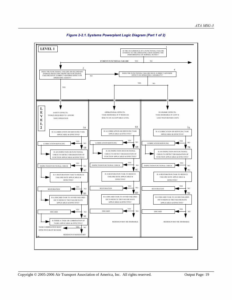
Figure 2-2.1. Systems Powerplant Logic Diagram (Part 1 of 2)
DOES THE FUNCTIONAL FAILURE OR SECONDARYDAMAGE RESULTING FROM THE FUNCTIONALFAILURE HAVE A DIRECT ADVERSE EFFECT ON
OPERATING SAFETY?
DOES THE FUNCTIONAL FAILURE HAVE A DIRECT ADVERSEEFFECT ON OPERATING CAPABILITY?
SAFETY EFFECTS:TASK(S) REQUIRED TO ASSURE
SAFE OPERATION
OPERATIONAL EFFECTS:TASK DESIRABLE IF IT REDUCES
RISK TO AN ACCEPTABLE LEVEL
ECONOMIC EFFECTS:TASK DESIRABLE IF COST IS
LESS THAN REPAIR COSTS
LUBRICATION/SERVICING
INSPECTION/FUNCTIONAL CHECK
RESTORATION
TASK/COMBINATION MOST
EFFECTIVE MUST BE DONE
REDESIGN IS MANDATORY
YESEVIDENT FUNCTIONAL FAILURE
YES
DISCARD
NO
NO
1
24
5A
5B
5C
5D
5E
SYSTEMS/POWERPLANTLOGIC DIAGRAM
FIGURE 1
LEVEL 1IS THE OCCURRENCE OF A FUNCTIONAL FAILUREEVIDENT TO THE OPERATING CREW DURING THE
PERFORMANCE OF NORMAL DUTIES ?
LEVEL2
IS A LUBRICATION OR SERVICING TASKAPPLICABLE & EFFECTIVE?
IS AN INSPECTION OR FUNCTIONALCHECK TO DETECT DEGRADATION OFFUNCTION APPLICABLE & EFFECTIVE?
IS A RESTORATION TASK TO REDUCEFAILURE RATE APPLICABLE &
EFFECTIVE?
IS A DISCARD TASK TO AVOID FAILURESOR TO REDUCE THE FAILURE RATE
APPLICABLE & EFFECTIVE?
IS THERE A TASK OR COMBINATION OFTASKS APPLICABLE & EFFECTIVE?
LUBRICATION/SERVICING
INSPECTION/FUNCTIONAL CHECK
RESTORATION
REDESIGN MAY BE DESIRABLE
DISCARD
6A
6B
6C
6D
IS A LUBRICATION OR SERVICING TASKAPPLICABLE & EFFECTIVE?
IS AN INSPECTION OR FUNCTIONAL
CHECK TO DETECT DEGRADATION OFFUNCTION APPLICABLE & EFFECTIVE?
IS A RESTORATION TASK TO REDUCEFAILURE RATE APPLICABLE &
EFFECTIVE?
IS A DISCARD TASK TO AVOID FAILURESOR TO REDUCE THE FAILURE RATE
APPLICABLE & EFFECTIVE?
LUBRICATION/SERVICING
INSPECTION/FUNCTIONAL CHECK
RESTORATION
DISCARD
7A
7B
7C
7D
IS A LUBRICATION OR SERVICING TASKAPPLICABLE & EFFECTIVE?
IS AN INSPECTION OR FUNCTIONALCHECK TO DETECT DEGRADATION OFFUNCTION APPLICABLE & EFFECTIVE?
IS A RESTORATION TASK TO REDUCEFAILURE RATE APPLICABLE &
EFFECTIVE?
IS A DISCARD TASK TO AVOID FAILURESOR TO REDUCE THE FAILURE RATE
APPLICABLE & EFFECTIVE?
YES
REDESIGN MAY BE DESIRABLE
NOYES
YESNO
NOYES
YESNO
NOYES
YESNO
NOYES
YESNO
NOYES
NOYES
YESNO
NOYES
YESNO
DN
NO

ATA MSG-3
Copyright © 2005-2006 Air Transport Association of America, Inc. All rights reserved. Output Page: 20
Figure 2-2.1. Systems Powerplant Logic Diagram (Part 2 of 2)
SAFETY EFFECTS:
TASK(S) REQUIRED TO ASSURE THE AVAILABILITY
NECESSARY TO AVOID EFFECTS OF MULTIPLE FAILURES
NON-SAFETY EFFECTS:
TASK(S) DESIRABLE TO ASSURE THE AVAILABILITY NECESSARY
TO AVOID ECONOMIC EFFECTS OF MULTIPLE FAILURES
LUBRICATION/SERVICING
INSPECTION/FUNCTIONAL CHECK
RESTORATION
TASK/COMBINATION MOST
EFFECTIVE MUST BE DONE
REDESIGN IS MANDATORY
YES
DISCARD
8A
8C
8D
8E
8F
SYSTEMS/POWERPLANTLOGIC DIAGRAM
FIGURE 1 (CONT’D.)
LEVEL 1
LEVEL2
IS A LUBRICATION OR SERVICING TASK
APPLICABLE & EFFECTIVE?
IS AN INSPECTION OR FUNCTIONAL
CHECK TO DETECT DEGRADATION OF
FUNCTION APPLICABLE & EFFECTIVE?
IS A RESTORATION TASK TO REDUCE
FAILURE RATE APPLICABLE &
EFFECTIVE?
IS A DISCARD TASK TO AVOID FAILURES
OR TO REDUCE THE FAILURE RATE
APPLICABLE & EFFECTIVE?
IS THERE A TASK OR COMBINATION OF
TASKS APPLICABLE & EFFECTIVE?
HIDDEN FUNCTIONAL FAILURE
NOYES
YES
NO
NOYES
YESNO
NOYES
DOES THE COMBINATION OF A HIDDEN FUNCTIONALFAILURE AND ONE ADDITIONAL FAILURE OF A SYSTEM
RELATED OR BACKUP FUNCTION HAVE AN ADVERSEEFFECT ON OPERATING SAFETY ?
NO
OPERATIONAL/VISUAL CHECK
8B
IS A CHECK TO VERIFY OPERATION
APPLICABLE & EFFECTIVE ?
YESNO
LUBRICATION/SERVICING
INSPECTION/FUNCTIONAL CHECK
RESTORATION
REDESIGN IS DESIRABLE
DISCARD
9A
9C
9D
9E
IS A LUBRICATION OR SERVICING TASK
APPLICABLE & EFFECTIVE?
IS AN INSPECTION OR FUNCTIONAL
CHECK TO DETECT DEGRADATION OF
FUNCTION APPLICABLE & EFFECTIVE?
IS A RESTORATION TASK TO REDUCE
FAILURE RATE APPLICABLE &
EFFECTIVE?
IS A DISCARD TASK TO AVOID FAILURES
OR TO REDUCE THE FAILURE RATE
APPLICABLE & EFFECTIVE?
NOYES
YESNO
NOYES
YESNO
OPERATIONAL/VISUAL CHECK
9B
IS A CHECK TO VERIFY OPERATION
APPLICABLE & EFFECTIVE ?
YES
NO
DN
3

ATA MSG-3
Copyright © 2005-2006 Air Transport Association of America, Inc. All rights reserved. Output Page: 21
2-3. Aircraft Systems/Powerplant Analysis Procedure
The method for determining the scheduled maintenance tasks and intervals for systems/powerplant, including componentsand APU's, uses a progressive logic diagram. A glossary of terms and definitions used in the logic diagram is listed inAppendix A. This logic is the basis of an evaluation technique applied to each maintenance significant item (system,sub-system, module, component, accessory, unit, part, etc.), using the technical data available. Principally, the evaluationsare based on the item's functional failures and failure causes.
2-3-1. MSI Selection
Before the actual MSG-3 logic can be applied to an item, the aircraft's significant systems and components must beidentified.
Maintenance Significant Items (MSIs) are items fulfilling defined selection criteria (see Step 3., below) for which MSIanalyses are established at the highest manageable level.
This process of identifying Maintenance Significant Items is a conservative process (using engineering judgment) based onthe anticipated consequences of failure. The top-down approach is a process of identifying the significant items on theaircraft at the highest manageable level.
The MSI selection process is outlined below:
1. Step 1.
The manufacturer partitions the aircraft into major functional areas; ATA Systems and Subsystems. This process continuesuntil all on-aircraft replaceable components have been identified.
NOTE: Items within the Structural ATA Chapters (51-57) that lend themselves to System analysis (e.g.,fuselage drains, door mechanisms, etc.) should be included in this step. In addition, allsafety/emergency systems or equipment should also be included.
2. Step 2.
Using a top-down approach, the manufacturer establishes the list of items to which the MSI selection questions will beapplied.
NOTE: Regulatory policy developed for fuel tank system safety Instructions for Continued Airworthiness(ICA), requires the identification of design features that may result in development of ignition sources inthe fuel tank systems; e.g., the bonding subsystem to carry electrical current generated in the event oflightning, and the wire harnesses in an around fuel tanks that maintain separation to prevent wirecontact/chafing. These design features are to be included in MSI selection and analysis.
3. Step 3
The manufacturer applies the following questions to the list of items identified in Step 2:

ATA MSG-3
Copyright © 2005-2006 Air Transport Association of America, Inc. All rights reserved. Output Page: 22
a) Could failure be undetectable or not likely to be detected by the operating crew during normal duties?
b) Could failure affect safety (on ground or in flight), including safety/emergency systems or equipment?
c) Could failure have significant operational impact?
d) Could failure have significant economic impact?
4. Step 4a) For those items for which at least one of the four questions is answered with a "YES," MSG-3 analysis is required,
and the highest manageable level must be confirmed (see Step 2, above). Consideration should be given toselecting a higher manageable level that includes this item as part of that higher-level system.
An MSI is usually a system or sub-system, and is, in most cases, one level above the lowest (on-aircraft) levelidentified in Step 1. This level is considered the highest manageable level; i.e., one which is high enough to avoidunnecessary analysis, but low enough to be properly analyzed and ensure that all functions, functional failures andfailure causes are covered.
b) For those items for which all four questions are answered with a "NO," MSG-3 analysis is not required and furtherMSI selection analysis is not necessary at lower levels. Additionally, the lower-level items should be listed toidentify those that will not be further assessed. This list must be presented by the manufacturer to the ISC forreview and approval.
5. Step 5
Once the highest manageable level is confirmed per Step 4, the resulting list of items is now considered the "Candidate MSIList," and is presented by the manufacturer to the ISC. The ISC, in turn, reviews and approves this list for subsequentdistribution to the Working Groups.
6. Step 6
The Working Groups will review the Candidate MSI List, and through application of MSG-3 analysis, validate the selectedhighest manageable level or (if required) propose modification of the MSI list to the ISC. The primary aim of the WorkingGroup review is to verify that no significant item has been overlooked, and that the right level for the analysis has beenchosen.
NOTE: Although an item may be selected as an MSI and will be analyzed, this does not imply that a task willnecessarily result from the analysis.

ATA MSG-3
Copyright © 2005-2006 Air Transport Association of America, Inc. All rights reserved. Output Page: 23
2-3-2. Analysis Procedure
After the MSI's have been selected, the following must be identified for each MSI:
a) Function(s) - the normal characteristic actions of an item
b) Functional Failure(s) - Failure of an item to perform its intended function within specified limits
c) Failure Effect(s) - what is the result of a functional failure
d) Failure Cause(s) - why the functional failure occurs
Defining some functional failures may require a detailed understanding of the system and its design principles. For example,for system components having single element dual load path features, such as concentric tubes or back-to-back plates, thefunction of both paths should be analyzed individually. The degradation and/or failure of one path may not be evident.
When listing functions, functional failures, failure effects, and failure causes, care should be taken to identify the functionsof all protective devices. These include devices with the following functions:
a) to draw the attention of the operating crew to abnormal conditions
b) to shut down equipment in the event of a failure
c) to eliminate or relieve abnormal conditions which follow a failure
d) to take over from a function that has failed
Protective function statements should describe the protective function itself, and should also include the words "if" or "in theevent of" followed by a brief description of the events or circumstances that would activate or require activation of theprotection. For example, "To open the relief valve to atmosphere in the event of system X pressure exceeding 300 psi."
Tasks and intervals required in the scheduled maintenance are identified using the procedures set forth herein. Both theeconomic and safety related tasks are included so as to produce initial scheduled maintenance tasks/intervals.
All available Vendor Recommendations (VR) should be fully considered, discussed in the MWG meetings, and acceptedonly if they are applicable and effective according to MSG-3 criteria.
Prior to applying the MSG-3 logic diagram to an item, a preliminary work sheet will be completed that clearly defines theMSI, its function(s), functional failure(s), failure effect(s), failure cause(s) and any additional data pertinent to the item; e.g.,ATA chapter reference, fleet applicability, manufacturer's part number, a brief description of the item, expected failure rate,hidden functions, need to be on M.E.L., redundancy (may be unit, system or system management), etc. This work sheet is tobe designed to meet the user's requirements and will be included as part of the total MSG-3 documentation for the item.
The approach taken in the following procedure is to provide a logic path for each functional failure. Each functional failureand failure cause must be processed through the logic so that a judgment will be made as to the necessity of a task. Theresultant tasks and intervals will form the initial scheduled maintenance.
ATA MSG-3
Copyright © 2005-2006 Air Transport Association of America, Inc. All rights reserved. Output Page: 24
2-3-3. Logic Diagram
The decision logic diagram (Ref. [Figure 2-2.1]) is used for analysis of systems/powerplant items. The logic flow isdesigned whereby the user begins the analysis at the top of the diagram, and answers to the "YES" or "NO" questions willdictate direction of the analysis flow.
1. Levels of Analysis
The decision logic has two levels (Ref. [Figure 2-2.1])
a) Level 1 (questions 1, 2, 3 and 4) requires the evaluation of each FUNCTIONAL FAILURE for determination of theFailure Effect Category; i.e., safety, operational, economic, hidden safety or hidden non-safety.
b) Level 2 (questions 5, 6 , 7, 8 and 9, "A" through "F", as applicable) then takes the FAILURE CAUSE(S) for eachfunctional failure into account for selecting the specific type of task(s).
At level 2, the task selection section, paralleling and default logic have been introduced. Regardless of the answerto the first question regarding "Lubrication/Servicing", the next task selection question must be asked in all cases.When following the hidden or evident safety effects path, all subsequent questions must be asked. In the remainingcategories, subsequent to the first question, a "YES" answer will allow exiting the logic.
NOTE: At the user's option, advancement to subsequent questions after deriving a "YES" answer is allowable,but only until the cost of the task is equal to the cost of the failure prevented.
Default logic is reflected in paths outside the safety effects areas by the arrangement of the task selection logic. Inthe absence of adequate information to answer "YES" or "NO" to questions in the second level, default logicdictates a "NO" answer be given and the subsequent question be asked. As "NO" answers are generated the onlychoice available is the next question, which in most cases provides a more conservative, stringent and/or costlytask.

ATA MSG-3
Copyright © 2005-2006 Air Transport Association of America, Inc. All rights reserved. Output Page: 25
2-3-4. Procedure
This procedure requires consideration of the functional failures, failure causes, and the applicability/ effectiveness of eachtask. Each functional failure processed through the logic will be directed into one of five Failure Effect categories [Subject2-3-6].
Fault-Tolerant Systems
For the purposes of this MSG-3 analysis, a fault-tolerant system is defined as one that is designed with redundant elementsthat can fail without impact on safety or operating capability. In other words, redundant elements of the system may fail(fault), but the system itself has not failed. Individually, and in some combinations, these faults may not be annunciated tothe operating crew, but by design the aircraft may be operated indefinitely with the fault(s) while still satisfying allcertification and airworthiness requirements.
Consequently, this means that the implementation of fault-tolerant system design by the manufacturer enhances thein-service system availability.
MSG-3 is only to be applied to each MSI's functional failure and failure cause for the purpose of maintaining the inherentsafety and reliability levels of the aircraft [Subject 2-1-1.]; NOT to maintain enhanced in-service system availability. Tasksmay be used to enhance in-service availability by identifying the faults of the fault-tolerant system of operational oreconomic benefit to an operator. Such tasks are NOT developed by use of MSG-3, NOR should they be submitted for thesubsequent MRB report.

ATA MSG-3
Copyright © 2005-2006 Air Transport Association of America, Inc. All rights reserved. Output Page: 26
2-3-5. Consequences of Failure (First Level)
The decision logic diagram (Ref. [Figure 2-2.1]) facilitates the identification of the tasks required. There are four first levelquestions.
1. Evident or Hidden Functional Failure
QUESTION 1: IS THE OCCURRENCE OF A FUNCTIONAL FAILURE EVIDENT TOTHE OPERATING CREW DURING THE PERFORMANCE OF NORMALDUTIES?
This question asks if the operating crew will be aware of the loss (failure) of the function during performance of normaloperating duties. Question 1 must be asked for each functional failure of the item being analyzed. The intent is to segregatethe evident and hidden functional failures. The operating crew consists of qualified flight compartment and cabin attendantpersonnel who are on duty. Normal duties are those duties associated with the routine operation of the aircraft on a dailybasis.
If there is uncertainty about the frequency of use of certain systems, and assumptions are to be made, then the assumptionsmade must be recorded in the analysis for later verification. This applies equally to assumptions made concerning tests thatare performed automatically by electronic equipment.
Ground crew is not part of the operating crew.
Flight crew "normal duties" are described (in part) in the Airplane Flight Manual (AFM) and must be accomplished by theflight crew. Working groups may consider these flight crew checks part of the operating crew's "normal duties" for thepurpose of categorizing failures as evident in the MSG-3 analysis. It should be documented in the analysis whenever creditis taken for such flight crew checks.
Since the AFM is not available during the initial MSG-3 analysis, working groups should document all Level 1 failureanalysis that is based on flight crew checks assumed to be included in the AFM. Once the AFM is available, all Level 1analyses based on such assumptions must be verified to ensure that these checks are included in the AFM. Level 1 analysismust be redone for any assumed flight crew check not included in the AFM. System failures which are indicated to theoperating crew when performing their normal duties shall be considered as evident.
NOTE: Evidence of AFM tasks which are assumed in the MSG-3 Level 1 analysis submitted to the MRB must be availableprior to the MRB Report approval; otherwise, the MSG-3 Level 1 analysis submitted to the MRB must be based on theassumption that these tasks are not part of the crew's normal duties.
A "YES" answer indicates the functional failure is evident; proceed to Question 2 (Ref. [Heading 2-3-5.2]).
A "NO" answer indicates the functional failure is hidden; proceed to Question 3 (Ref. [Heading 2-3-5.3]).
ATA MSG-3
Copyright © 2005-2006 Air Transport Association of America, Inc. All rights reserved. Output Page: 27
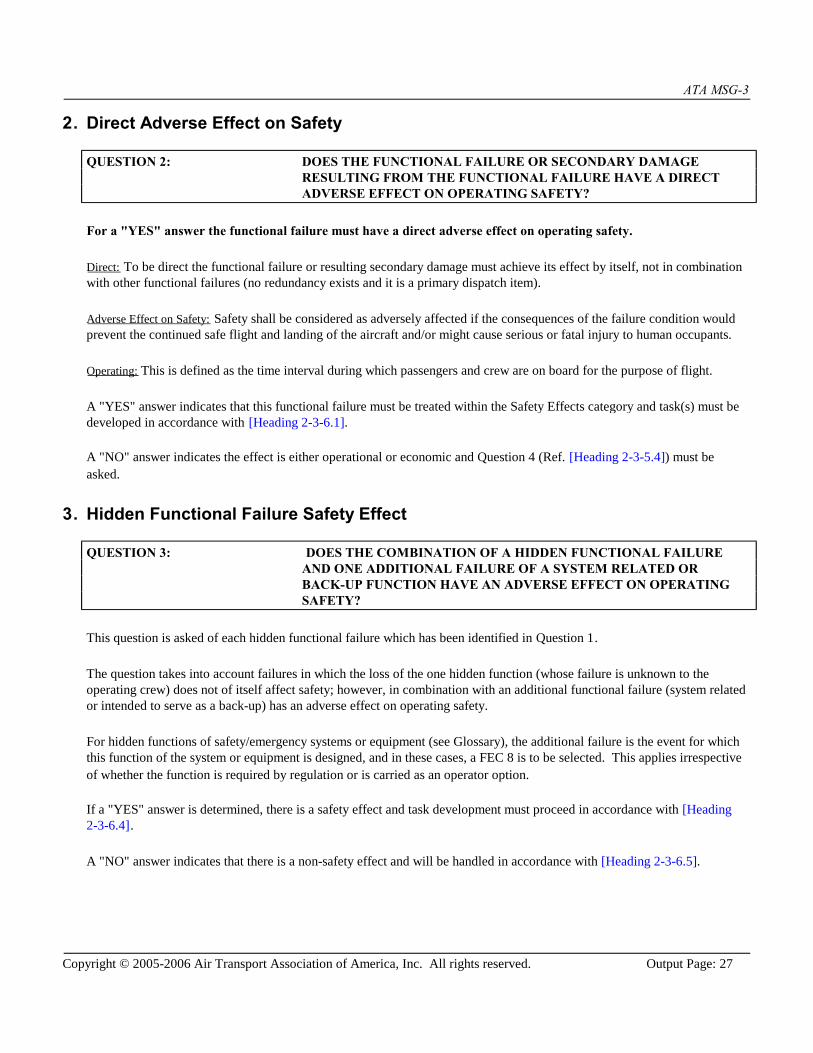
2. Direct Adverse Effect on Safety
QUESTION 2: DOES THE FUNCTIONAL FAILURE OR SECONDARY DAMAGERESULTING FROM THE FUNCTIONAL FAILURE HAVE A DIRECTADVERSE EFFECT ON OPERATING SAFETY?
For a "YES" answer the functional failure must have a direct adverse effect on operating safety.
Direct: To be direct the functional failure or resulting secondary damage must achieve its effect by itself, not in combinationwith other functional failures (no redundancy exists and it is a primary dispatch item).
Adverse Effect on Safety: Safety shall be considered as adversely affected if the consequences of the failure condition wouldprevent the continued safe flight and landing of the aircraft and/or might cause serious or fatal injury to human occupants.
Operating: This is defined as the time interval during which passengers and crew are on board for the purpose of flight.
A "YES" answer indicates that this functional failure must be treated within the Safety Effects category and task(s) must bedeveloped in accordance with [Heading 2-3-6.1].
A "NO" answer indicates the effect is either operational or economic and Question 4 (Ref. [Heading 2-3-5.4]) must beasked.
3. Hidden Functional Failure Safety Effect
QUESTION 3: DOES THE COMBINATION OF A HIDDEN FUNCTIONAL FAILUREAND ONE ADDITIONAL FAILURE OF A SYSTEM RELATED ORBACK-UP FUNCTION HAVE AN ADVERSE EFFECT ON OPERATINGSAFETY?
This question is asked of each hidden functional failure which has been identified in Question 1.
The question takes into account failures in which the loss of the one hidden function (whose failure is unknown to theoperating crew) does not of itself affect safety; however, in combination with an additional functional failure (system relatedor intended to serve as a back-up) has an adverse effect on operating safety.
For hidden functions of safety/emergency systems or equipment (see Glossary), the additional failure is the event for whichthis function of the system or equipment is designed, and in these cases, a FEC 8 is to be selected. This applies irrespectiveof whether the function is required by regulation or is carried as an operator option.
If a "YES" answer is determined, there is a safety effect and task development must proceed in accordance with [Heading2-3-6.4].
A "NO" answer indicates that there is a non-safety effect and will be handled in accordance with [Heading 2-3-6.5].

ATA MSG-3
Copyright © 2005-2006 Air Transport Association of America, Inc. All rights reserved. Output Page: 28
4. Operational Effect
QUESTION 4: DOES THE FUNCTIONAL FAILURE HAVE A DIRECT ADVERSEEFFECT ON OPERATING CAPABILITY?
This question asks if the functional failure could have an adverse effect on operating capability:
a) requiring either the imposition of operating restrictions or correction prior to further dispatch; or
b) requiring flight crew use of abnormal or emergency procedures.
This question is asked of each evident functional failure not having a direct adverse effect on safety. The answer maydepend on the type of operation.
The assessment of whether or not a failure has an effect on operating capability may require consultation of the MMELand/or other documentation with operational procedures. As the documents necessary to assess the effect on operatingcapability are normally not available during the initial MSG-3 analysis, working groups should document all Level 1 failureanalyses based on assumptions regarding question 4. Once the affected documents become available, all Level 1 analysesbased on such assumptions must be verified.
If the answer to this question is "YES", the effect of the functional failure has an adverse effect on operating capability, andtask selection will be handled in accordance with [Heading 2-3-6.2].
A "NO" answer indicates that there is an economic effect and should be handled in accordance with [Heading 2-3-6.3].

ATA MSG-3
Copyright © 2005-2006 Air Transport Association of America, Inc. All rights reserved. Output Page: 29
2-3-6. Failure Effect Categories (First Level)
Once the analysts have answered the applicable first level questions, they are directed to one of the five Effect Categories
a) Evident Safety (Category 5)
b) Evident Operational (Category 6)
c) Evident Economic (Category 7)
d) Hidden Safety (Category 8)
e) Hidden Non-Safety (Category 9)
ATA MSG-3
Copyright © 2005-2006 Air Transport Association of America, Inc. All rights reserved. Output Page: 30
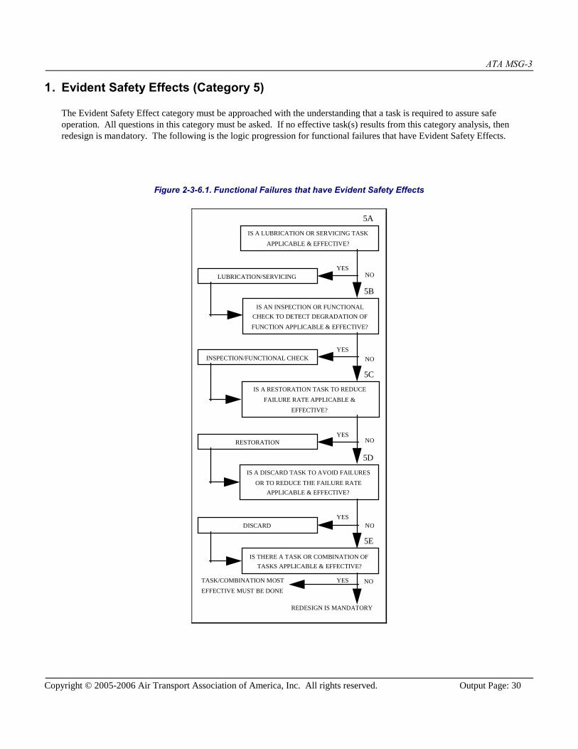
1. Evident Safety Effects (Category 5)
The Evident Safety Effect category must be approached with the understanding that a task is required to assure safeoperation. All questions in this category must be asked. If no effective task(s) results from this category analysis, thenredesign is mandatory. The following is the logic progression for functional failures that have Evident Safety Effects.
Figure 2-3-6.1. Functional Failures that have Evident Safety Effects
LUBRICATION/SERVICING
INSPECTION/FUNCTIONAL CHECK
RESTORATION
TASK/COMBINATION MOST
EFFECTIVE MUST BE DONE
REDESIGN IS MANDATORY
DISCARD
5A
5B
5C
5D
5E
IS A LUBRICATION OR SERVICING TASK
APPLICABLE & EFFECTIVE?
IS AN INSPECTION OR FUNCTIONALCHECK TO DETECT DEGRADATION OF
FUNCTION APPLICABLE & EFFECTIVE?
IS A RESTORATION TASK TO REDUCE
FAILURE RATE APPLICABLE &
EFFECTIVE?
IS A DISCARD TASK TO AVOID FAILURES
OR TO REDUCE THE FAILURE RATEAPPLICABLE & EFFECTIVE?
IS THERE A TASK OR COMBINATION OFTASKS APPLICABLE & EFFECTIVE?
NOYES
YESNO
NOYES
YESNO
NOYES

ATA MSG-3
Copyright © 2005-2006 Air Transport Association of America, Inc. All rights reserved. Output Page: 31
2. Evident Operational Effects (Category 6)
A task(s) is desirable if it reduces the risk of failure to an acceptable level. Analysis of the failure causes through the logicrequires the first question (Lubrication/Servicing) to be answered. Either a "YES" or "NO" answer of question "A" stillrequires movement to the next level; from this point on, a "YES" answer will complete the analysis and the resultant task(s)will satisfy the requirements. If all answers are "NO", then no task has been generated. If operational penalties are severe, aredesign may be desirable. The following is the logic progression for functional failures that have Evident OperationalEffects.
Figure 2-3-6.2.Functional Failures that have Evident Operational Effects
LUBRICATION/SERVICING
INSPECTION/FUNCTIONAL CHECK
RESTORATION
REDESIGN MAY BE DESIRABLE
DISCARD
6A
6B
6C
6D
IS A LUBRICATION OR SERVICING TASK
APPLICABLE & EFFECTIVE?
IS AN INSPECTION OR FUNCTIONAL
CHECK TO DETECT DEGRADATION OF
FUNCTION APPLICABLE & EFFECTIVE?
IS A RESTORATION TASK TO REDUCE
FAILURE RATE APPLICABLE &
EFFECTIVE?
IS A DISCARD TASK TO AVOID FAILURES
OR TO REDUCE THE FAILURE RATE
APPLICABLE & EFFECTIVE?
YESNO
NOYES
YESNO
NOYES

ATA MSG-3
Copyright © 2005-2006 Air Transport Association of America, Inc. All rights reserved. Output Page: 32
3. Evident Economic Effects (Category 7)
A task(s) is desirable if the cost of the task is less than the cost of repair. Analysis of the failure causes through the logicrequires the first question (Lubrication/Servicing) to be answered. Either a "YES" or "NO" answer to question "A" stillrequires movement to the next level; from this point on, a "YES" answer will complete the analysis and the resultant task(s)will satisfy the requirements. If all answers are "NO", no task has been generated. If economic penalties are severe, aredesign may be desirable. The following is the logic progression for functional failures that have Evident EconomicEffects.
Figure 2-3-6.3. Functional Failures that have Evident Economic Effects
LUBRICATION/SERVICING
INSPECTION/FUNCTIONAL CHECK
RESTORATION
DISCARD
7A
7B
7C
7D
IS A LUBRICATION OR SERVICING TASK
APPLICABLE & EFFECTIVE?
IS AN INSPECTION OR FUNCTIONAL
CHECK TO DETECT DEGRADATION OF
FUNCTION APPLICABLE & EFFECTIVE?
IS A RESTORATION TASK TO REDUCE
FAILURE RATE APPLICABLE &
EFFECTIVE?
IS A DISCARD TASK TO AVOID FAILURES
OR TO REDUCE THE FAILURE RATE
APPLICABLE & EFFECTIVE?
REDESIGN MAY BE DESIRABLE
NOYES
YESNO
NOYES
YESNO
ATA MSG-3
Copyright © 2005-2006 Air Transport Association of America, Inc. All rights reserved. Output Page: 33
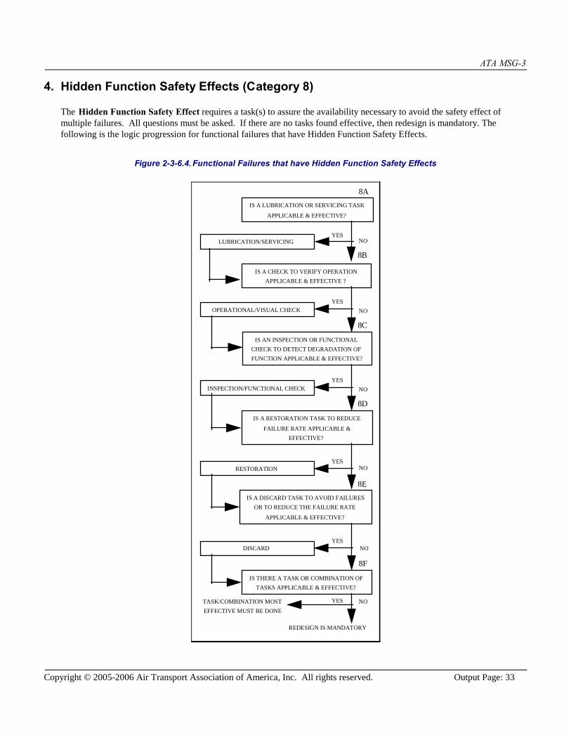
4. Hidden Function Safety Effects (Category 8)
The Hidden Function Safety Effect requires a task(s) to assure the availability necessary to avoid the safety effect ofmultiple failures. All questions must be asked. If there are no tasks found effective, then redesign is mandatory. Thefollowing is the logic progression for functional failures that have Hidden Function Safety Effects.
Figure 2-3-6.4.Functional Failures that have Hidden Function Safety Effects
LUBRICATION/SERVICING
INSPECTION/FUNCTIONAL CHECK
RESTORATION
TASK/COMBINATION MOST
EFFECTIVE MUST BE DONE
REDESIGN IS MANDATORY
DISCARD
8A
8C
8D
8E
8F
IS A LUBRICATION OR SERVICING TASK
APPLICABLE & EFFECTIVE?
IS AN INSPECTION OR FUNCTIONAL
CHECK TO DETECT DEGRADATION OF
FUNCTION APPLICABLE & EFFECTIVE?
IS A RESTORATION TASK TO REDUCE
FAILURE RATE APPLICABLE &
EFFECTIVE?
IS A DISCARD TASK TO AVOID FAILURES
OR TO REDUCE THE FAILURE RATE
APPLICABLE & EFFECTIVE?
IS THERE A TASK OR COMBINATION OF
TASKS APPLICABLE & EFFECTIVE?
NOYES
YES
NO
NOYES
YESNO
NOYES
OPERATIONAL/VISUAL CHECK
8B
IS A CHECK TO VERIFY OPERATION
APPLICABLE & EFFECTIVE ?
YES
NO

ATA MSG-3
Copyright © 2005-2006 Air Transport Association of America, Inc. All rights reserved. Output Page: 34
5. Hidden Function Non-Safety Effects (Category 9)
The Hidden Function Non-Safety Effect category indicates that a task(s) may be desirable to assure the availabilitynecessary to avoid the economic effects of multiple failures. Movement of the failure causes through the logic requires thefirst question (Lubrication/Servicing) to be answered. Either a "YES" or "NO" answer still requires movement to the nextlevel; from this point on, a "YES" answer will complete the analysis and the resultant task(s) will satisfy the requirements. Ifall answers are "NO", no task has been generated. If economic penalties are severe, a redesign may be desirable. Thefollowing is the logic progression for functional failures that have Hidden Function Non-Safety Effects.
Figure 2-3-6.5.Functional Failures that have Hidden Function Non-Safety Effects
LUBRICATION/SERVICING
INSPECTION/FUNCTIONAL CHECK
RESTORATION
REDESIGN IS DESIRABLE
DISCARD
9A
9C
9D
9E
IS A LUBRICATION OR SERVICING TASK
APPLICABLE & EFFECTIVE?
IS AN INSPECTION OR FUNCTIONAL
CHECK TO DETECT DEGRADATION OF
FUNCTION APPLICABLE & EFFECTIVE?
IS A RESTORATION TASK TO REDUCE
FAILURE RATE APPLICABLE &
EFFECTIVE?
IS A DISCARD TASK TO AVOID FAILURES
OR TO REDUCE THE FAILURE RATE
APPLICABLE & EFFECTIVE?
NOYES
YES
NO
NOYES
YESNO
OPERATIONAL/VISUAL CHECK
9B
IS A CHECK TO VERIFY OPERATION
APPLICABLE & EFFECTIVE ?
YES
NO
ATA MSG-3
Copyright © 2005-2006 Air Transport Association of America, Inc. All rights reserved. Output Page: 35
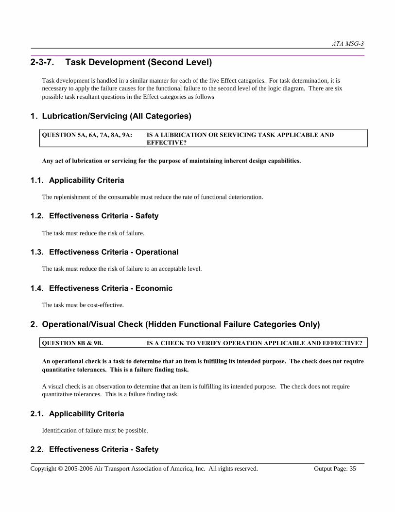
2-3-7. Task Development (Second Level)
Task development is handled in a similar manner for each of the five Effect categories. For task determination, it isnecessary to apply the failure causes for the functional failure to the second level of the logic diagram. There are sixpossible task resultant questions in the Effect categories as follows
1. Lubrication/Servicing (All Categories)
QUESTION 5A, 6A, 7A, 8A, 9A: IS A LUBRICATION OR SERVICING TASK APPLICABLE ANDEFFECTIVE?
Any act of lubrication or servicing for the purpose of maintaining inherent design capabilities.
1.1. Applicability Criteria
The replenishment of the consumable must reduce the rate of functional deterioration.
1.2. Effectiveness Criteria - Safety
The task must reduce the risk of failure.
1.3. Effectiveness Criteria - Operational
The task must reduce the risk of failure to an acceptable level.
1.4. Effectiveness Criteria - Economic
The task must be cost-effective.
2. Operational/Visual Check (Hidden Functional Failure Categories Only)
QUESTION 8B & 9B. IS A CHECK TO VERIFY OPERATION APPLICABLE AND EFFECTIVE?
An operational check is a task to determine that an item is fulfilling its intended purpose. The check does not requirequantitative tolerances. This is a failure finding task.
A visual check is an observation to determine that an item is fulfilling its intended purpose. The check does not requirequantitative tolerances. This is a failure finding task.
2.1. Applicability Criteria
Identification of failure must be possible.
2.2. Effectiveness Criteria - Safety

ATA MSG-3
Copyright © 2005-2006 Air Transport Association of America, Inc. All rights reserved. Output Page: 36
The task must ensure adequate availability of the hidden function to reduce the risk of a multiple failure.
2.3. Effectiveness Criteria - Economic
The task must ensure adequate availability of the hidden function in order to avoid economic effects of multiple failures andmust be cost-effective.
3. Inspection/Functional Check (All Categories)
QUESTION 5B, 6B, 7B, 8C & 9C. IS AN INSPECTION OR FUNCTIONAL CHECK TO DETECTDEGRADATION OF FUNCTION APPLICABLE AND EFFECTIVE?
An inspection is:
A. GENERAL VISUAL INSPECTION (GVI)
A visual examination of an interior or exterior area, installation or assembly to detect obvious damage, failure orirregularity. This level of inspection is made from within touching distance, unless otherwise specified. A mirrormay be necessary to enhance visual access to all exposed surfaces in the inspection area. This level of inspection ismade under normally available lighting conditions such as daylight, hangar lighting, flashlight or drop-light andmay require removal or opening of access panels or doors. Stands, ladders or platforms may be required to gainproximity to the area being checked.
OR
B. DETAILED INSPECTION (DET)
An intensive examination of a specific item, installation or assembly to detect damage, failure or irregularity.Available lighting is normally supplemented with a direct source of good lighting at an intensity deemedappropriate. Inspection aids such as mirrors, magnifying lenses, etc. may be necessary. Surface cleaning andelaborate access procedures may be required.
OR
C. SPECIAL DETAILED INSPECTION (SDI)
An intensive examination of a specific item, installation, or assembly to detect damage, failure or irregularity. Theexamination is likely to make extensive use of specialized Inspection Techniques and/or equipment. Intricatecleaning and substantial access or disassembly procedure may be required.
A functional check is a quantitative check to determine if one or more functions of an item performs within specified limits.
3.1. Applicability CriteriaReduced resistance to failure must be detectable, and there exists a reasonably consistent interval between adeterioration condition and functional failure.
3.2. Effectiveness Criteria - SafetyThe task must reduce the risk of failure to assure safe operation.

ATA MSG-3
Copyright © 2005-2006 Air Transport Association of America, Inc. All rights reserved. Output Page: 37
3.3. Effectiveness Criteria - OperationalThe task must reduce the risk of failure to an acceptable level.
3.4. Effectiveness Criteria - Economic
The task must be cost-effective; i.e., the cost of the task must be less than the cost of the failure prevented.
4. Restoration (All Categories)
QUESTION 5C, 6C, 7C, 8D, & 9D. IS A RESTORATION TASK TO REDUCE FAILURE RATE APPLICABLEAND EFFECTIVE?
That work necessary to return the item to a specific standard.
Since restoration may vary from cleaning or replacement of single parts up to a complete overhaul, the scope of eachassigned restoration task has to be specified.
4.1. Applicability Criteria
The item must show functional degradation characteristics at an identifiable age and a large proportion of units must surviveto that age. It must be possible to restore the item to a specific standard of failure resistance.
4.2. Effectiveness Criteria - Safety
The task must reduce the risk of failure to assure safe operation.
4.3. Effectiveness Criteria - Operational
The task must reduce the risk of failure to an acceptable level.
4.4. Effectiveness Criteria - Economic
The task must be cost-effective: i.e., the cost of the task must be less than the cost of the failure prevented.
5. Discard (All Categories)
QUESTION 5D, 6D, 7D, 8E, 9E IS A DISCARD TASK TO AVOID FAILURES OR TO REDUCE THEFAILURE RATE APPLICABLE AND EFFECTIVE?
The removal from service of an item at a specified life limit.
Discard tasks are normally applied to so-called single celled parts such as cartridges, canisters, cylinders, engine disks,safe-life structural members, etc.

ATA MSG-3
Copyright © 2005-2006 Air Transport Association of America, Inc. All rights reserved. Output Page: 38
5.1. Applicability Criteria
The item must show functional degradation characteristics at an identifiable age and a large proportion of units must surviveto that age.
5.2. Effectiveness Criteria - Safety
A safe-life limit must reduce the risk of failure to assure safe operation.
5.3. Effectiveness Criteria - Operational
The task must reduce the risk of failure to an acceptable level.
5.4. Effectiveness Criteria - Economic
An economic-life limit must be cost-effective: i.e., the cost of the task must be less than the cost of the failure prevented.
6. Combination (Safety Categories Only)
QUESTION 5E, 8F. IS THERE A TASK OR COMBINATION OF TASKS APPLICABLE ANDEFFECTIVE?
Since this is a safety category question and a task is required, all possible avenues must be analyzed. To do this, areview of the task(s) that are applicable is necessary. From this review the most effective task(s) must be selected.

ATA MSG-3
Copyright © 2005-2006 Air Transport Association of America, Inc. All rights reserved. Output Page: 39
7. Task Selection Criteria
Table 2-3-7.1.Criteria for Task Selection
TASK APPLICABILITY SAFETYEFFECTIVENESS
OPERATIONALEFFECTIVENESS
ECONOMICEFFECTIVENESS
LUBRICATIONOR SERVICING
The replenishment ofthe consumable mustreduce the rate offunctionaldeterioration.
The task must reducethe risk of failure.
The task must reducethe risk of failure toan acceptable level.
The task must be costeffective.
OPERATIONALOR VISUALCHECK
Identification offailure must bepossible.
The task must ensureadequate availabilityof the hidden functionto reduce the risk of amultiple failure.
Not applicable. The task must ensureadequate availabilityof the hidden functionin order to avoideconomic effects ofmultiple failures andmust be costeffective.
INSPECTION ORFUNCTIONALCHECK
Reduced resistance tofailure must bedetectable, and thereexists a reasonablyconsistent intervalbetween adeteriorationcondition andfunctional failure.
The task must reducethe risk of failure toassure safe operation.
The task must reducethe risk of failure toan acceptable level.
The task must be costeffective; i. e., thecost of the task mustbe less than the costof the failureprevented.
RESTORATION The item must showfunctionaldegradationcharacteristics at anidentifiable age, and alarge proportion ofunits must survive tothat age. It must bepossible to restore theitem to a specificstandard of failureresistance.
The task must reducethe risk of failure toassure safe operation.
The task must reducethe risk of failure toan acceptable level.
The task must be costeffective; i.e., the costof the task must beless than the cost ofthe failure prevented.
DISCARD The item must showfunctionaldegradationcharacteristics at anidentifiable age and alarge proportion ofunits must survive tothat age.
The safe life limitmust reduce the riskof failure to assuresafe operation.
The task must reducethe risk of failure toan acceptable level.
An economic lifelimit must be costeffective; i.e., the costof the task must beless than the cost ofthe failure prevented.

ATA MSG-3
Copyright © 2005-2006 Air Transport Association of America, Inc. All rights reserved. Output Page: 40
2-3-8. Systems/Powerplant Task Interval Determination
1. General
As part of the MSG-3 Logic-Analysis, the Maintenance Working Group (MWG) determines the interval of each scheduledmaintenance task that satisfies both the applicability & effectiveness criteria. The MWGs should select the most appropriateinterval for each maintenance task based on available data and good engineering judgment. In the absence of specific dataon failure rates & characteristics, intervals for systems tasks are largely determined based on service experience with similarsystems/components.
The information needed to determine optimum intervals is ordinarily not available until after the equipment enters service.In many cases previous experience with the same or a similar item serves as a guide. The difficulty of establishing "correct"intervals for maintenance tasks is essentially an information problem and one that continues throughout the operating life ofthe equipment.
A task should not be done more often than experience or other data suggests simply because it is easily accomplished (doingtasks more often than necessary increases the chance for maintenance-induced errors and may have an adverse effect onreliability and safety).
2. Sources of Information
The MWG should consider the following in determining the most appropriate task interval:
manufacturer's tests and technical analysis
manufacturer's data and/or vendor recommendations
customer requirements
service experience gained with comparable or identical components and subsystems
'best engineering estimates'
In order to arrive at the 'best initial' maintenance interval for each task, each MWG must assess the interval based on allrelevant data that is available. As part of this assessment, the MWG should consider answering the following questions inorder to determine the most appropriate interval:
What service experience is available for common/similar parts/components/systems on other aircraft that defines aneffective task interval?
What design improvements have been incorporated that warrant a longer interval between checks?
What task interval is recommended by the vendor/manufacturer based on test data or failure analysis?
3. Task Interval Parameters
Task intervals are established in terms of the measure of exposure to the conditions that cause the failure at which the task isdirected. The most widely used usage parameters are:

ATA MSG-3
Copyright © 2005-2006 Air Transport Association of America, Inc. All rights reserved. Output Page: 41
calendar time
flight hours
flight cycles
Engine/APU hours/cycles.
Task interval determination consists of identifying the correct usage parameter and its associated numerical interval or theappropriate letter check. Both intervals expressed in usage parameters and/or letter checks are acceptable and may be usedin line with specific procedures established for a given program. If an interval is to be expressed in a usage parameter,interval determination consists of the following steps:
The first step is to define the predominant (governing) usage parameter(s). For many Systems/Powerplant tasks,flight hours is the predominant usage parameter; however, for some tasks, flight cycles or calendar time may be thepredominant usage parameter. Intervals may also be expressed in terms of more than one usage parameter.
The second step is to determine the interval in terms of the selected usage parameter subject to the criteriadiscussed below.
As a matter of convenience, usage of letter checks for individual tasks and the establishment of a check interval frameworkmay be considered by the ISC; e.g., if no predominant usage parameter can be identified.
For some tasks, it may be appropriate for the MWG to consider specifying an initial interval that is different from the repeatinterval.
4. Task Interval Selection Criteria
In addition to the general guidelines included in [Heading 2-3-8.1], the following detailed recommendations should beconsidered:
Lubrication/Servicing (failure prevention):
The interval should be based on the consumable's usage rate, the amount of consumable in the storagecontainer (if applicable) and the deterioration characteristics.
Typical operating environments and climatic conditions are to be considered when assessing the deteriorationcharacteristics.
Operational Checks & Visual Checks (failure-finding):
Consider the length of potential exposure time to a hidden failure and the potential consequences if the hiddenfunction is unavailable.
Task intervals should be based on the need to reduce the probability of the associated multiple failure to a levelconsidered tolerable by the MWG.
The failure-finding task and associated interval selection process should take into account any probability thatthe task itself might leave the hidden function in a failed state.
Inspections & Functional checks (potential failure finding):
There should exist a clearly defined potential failure condition.
The task interval should be less than the shortest likely interval between the point at which a potential failure
ATA MSG-3
Copyright © 2005-2006 Air Transport Association of America, Inc. All rights reserved. Output Page: 42
becomes detectable and the point at which it degrades into a functional failure. (If the specific failure data isavailable, this interval may be referred to as the P to F interval.)
It should be practical to do the task at this interval.
The shortest time between the discovery of a potential failure and the occurrence of the functional failureshould be long enough for an appropriate action to be taken to avoid, eliminate or minimize the consequencesof the failure mode.
Restoration and Discard (failure avoidance):
Intervals should be based on the "identifiable age" when significant degradation begins and where theconditional probability of failure increases significantly.
Vendor recommendations based on in-service experience of similar parts should also be taken intoconsideration.
A sufficiently large proportion of the occurrences of this failure should occur after this age to reduce theprobability of premature failure to a level that is tolerable.
5. "Access-Defined" Inspection Intervals
Occasionally, it is impossible to accomplish a task until a component/system is removed/displaced; the interval of such atask should be coordinated with the removal/displacement of that component/system.
If the component/system is removed/displaced at intervals shorter than what is required for the task, then the task intervalshould be defined by the MWG as the removal/displacement interval (scheduled or unscheduled). If the task interval isshorter than the removal/displacement interval, then an access-defined interval is not appropriate.
NOTE: If the MWG selects an access-defined interval, consideration should be given to defining a minimuminterval between tasks. For example, if "Engine Change" is the access-defined interval, and the engineis removed soon after the last engine change due to an unscheduled event, the task should not berepeated unless a minimum number of hours have elapsed.
6. Certification Maintenance Requirements (CMRs)
In addition to those tasks and intervals established through MSG-3 analysis, scheduled maintenance tasks may arise withinthe FAR 25.1309 certification process.
A CMR is a required periodic task, established during the design certification of the airplane as an operating limitation ofthe type certificate. CMRs are a subset of the tasks identified during the type certification process. CMRs usually resultfrom a formal, numerical analysis conducted to show compliance with catastrophic and hazardous failure conditions. ACMR is intended to detect safety significant latent failures that would, in combination with one or more other specificfailures or events, result in a hazardous or catastrophic failure condition.
It is important to note that CMRs are derived from a fundamentally different analysis process than the maintenance tasks andintervals that result from MSG-3 analysis. The process for coordinating MSG-3 derived tasks with CMRs is described indetail in AC 25-19 and involves a Certification Maintenance Coordination Committee (CMCC) that may influence theMWG's interval decision.

ATA MSG-3
Copyright © 2005-2006 Air Transport Association of America, Inc. All rights reserved. Output Page: 43
7. Sampling
Sampling may be established for items defined in the Systems and Powerplant Analysis Procedures.
Sampling is an examination of a specific number of items at defined intervals in order to confirm that there are nounexpected degradation characteristics. Non-sampled items may continue in service until sampling results highlight theneed for additional scheduled maintenance.

ATA MSG-3
Copyright © 2005-2006 Air Transport Association of America, Inc. All rights reserved. Output Page: 44
2-4. Aircraft Structural Analysis Procedure
This section contains guidelines for developing scheduled maintenance tasks for aircraft structure. These are designed torelate the scheduled maintenance tasks to the consequences of structural damage remaining undetected. Each structural itemis assessed in terms of its significance to continuing airworthiness, susceptibility to any form of damage, and the degree ofdifficulty involved in detecting such damage. Once this is established, scheduled structural maintenance can be developedwhich can be shown to be effective in detecting and preventing structural degradation due to fatigue, environmentaldeterioration, or accidental damage throughout the operational life of the aircraft. The structural maintenance task(s)developed as part of the scheduled structural maintenance are used to satisfy aircraft type certification and MRBrequirements.
Mandatory replacement times for structural safe-life parts are included in the Airworthiness Limitations, required by theregulatory authorities as part of the Instructions for Continued Airworthiness. Some of the items requiring fatigue relatedinspections may also be included, as well as specific Corrosion Prevention and Control Program (CPCP) tasks whichsubsequently warrant inclusion, based on the in-service experience of the operators.
Requirements for detecting Accidental Damage (AD), Environmental Deterioration (ED), Fatigue Damage (FD), andprocedures for preventing and/or controlling corrosion form the basis for the MRB structural maintenance. However, all FDinspection requirements may not be available when the aircraft enters service. In such cases the manufacturer shall propose,prior to the entry of the aircraft into service, an appropriate time frame for completing the FD inspection requirements.
If the need arises, procedures should be developed for any new material (e.g., new composite material) whose damagecharacteristics do not follow those procedures described in this document

ATA MSG-3
Copyright © 2005-2006 Air Transport Association of America, Inc. All rights reserved. Output Page: 45
2-4-1. Aircraft Structure Defined
Aircraft structure consists of all load carrying members including wings, fuselage, empennage, engine mountings, landinggear, flight control surfaces and related points of attachment. The actuating portions of items such as landing gear, flightcontrols, doors, etc. will be treated as systems components and will be analyzed as described in [Section 2-3]. Attachmentof the actuators to the airframe will be treated as structure.
1. Significant and Other Structure
Structure can be subdivided into items according to the consequences of their failure to aircraft safety as follows
a. A Structural Significant Item (SSI) is any detail, element or assembly, which contributes significantly to carryingflight, ground, pressure or control loads, and whose failure could affect the structural integrity necessary for thesafety of the aircraft.
SSIs must not be confused with Principal Structural Elements, PSE (FAR 25.571); however, all PSEs must beaddressed by the SSIs.
b. Other Structure is that which is judged not to be a Structural Significant Item. It is defined both externally andinternally within zonal boundaries.

ATA MSG-3
Copyright © 2005-2006 Air Transport Association of America, Inc. All rights reserved. Output Page: 46
2-4-2. Scheduled Structural Maintenance
The primary objective of the scheduled structural maintenance is to maintain the inherent airworthiness throughout theoperational life of the aircraft in an economical manner. To achieve this, the inspections must meet the detectionrequirements from each of the AD, ED and FD assessments. Full account may be taken of all applicable inspectionsoccurring in the fleet.
Inspections related to detection of AD/ED are applicable to all aircraft when they first enter service. Changes or adjustmentscan be made to these inspections based on individual operator experience, when approved by their local regulatory authority.
Additional maintenance tasks (related to ED in metallics) to control corrosion to Level 1 or better are applicable at athreshold which is established during the aircraft type certification process. These are based on manufacturer and operatorexperience with similar aircraft structure, taking into consideration differences in relevant design features e.g. choice ofmaterial, assembly process, corrosion protection systems, galley and toilet design etc. See also [Heading 2-4-2.5] entitledCorrosion Prevention and Control Program.
Non-metallic structure is susceptible to damage and/or deterioration (e.g., disbonding and delamination). Such structure thatis classified as an SSI will require inspections to ensure adequate strength throughout its operational life. Susceptibility tolong term deterioration is assessed with regard to the operating environment. Areas such as major attachments, joints withmetallic parts and areas of high stress levels are suggested as likely candidates for inspection.
Inspections related to FD detection in metals are applicable after a threshold, which is established during the aircraft typecertification process. At the time the fatigue related inspections are implemented, sampling can be used, where it isapplicable and effective. The fatigue related inspections are based directly on the manufacturer's approved damagetolerance evaluations and changes or adjustments by the operators require use of an approved procedure.
Inspections related to FD detection in non-metals should not be required if their design is based on a "no-damage growth"design philosophy, and substantiated by testing.
Where no service experience exists with similar structure, the structural maintenance requirements shall be based onmanufacturer's recommendations.
Proposed initial scheduled maintenance tasks, to be used as the basis for the structural maintenance, are established for eachaircraft type by the Industry Steering Committee on the basis of:
a. Operator experience
b. Manufacturer's proposals
c. Considerations of systems analysis requirements
1. Structural Maintenance Tasks
As part of the structural maintenance development procedure, applicable and effective structural maintenance tasks areselected for each deterioration process of the SSI. To assure a direct correlation between the structural damage toleranceevaluations and the structural maintenance, it is necessary to describe each task.
To all extents possible, the inspection methods specified in the tasks should use the standard set of definitions included inthe MSG-3 glossary. Changes and/or additions to the inspection methods and definitions must be approved by the Industry

ATA MSG-3
Copyright © 2005-2006 Air Transport Association of America, Inc. All rights reserved. Output Page: 47
Steering Committee.
2. Inspection Thresholds
The inspection threshold for each SSI inspection task is a function of the source of damage as follows:
a. Accidental Damage - The first inspection (threshold) for accidental damage normally corresponds to a periodequal to the defined repeat inspection interval, from the time of first entry into service.
b. Environmental Deterioration - The initial inspection thresholds for all levels of inspection are based on existingrelevant service experience, manufacturers recommendations, and/or a conservative age exploration process.
c. Fatigue Damage - Inspections directly related to fatigue damage detection will occur after a threshold(s) to beestablished by the manufacturer and approved by the appropriate regulatory authority Thresholds are normallyestablished as part of the damage tolerance certification requirements. These are subject to change as serviceexperience, additional testing, or analysis work is obtained.
3. Repeat Inspection Intervals
After each inspection has been conducted, the repeat interval sets the period until the next inspection:
a. Accidental Damage - The repeat interval should be based on operator and manufacturer experience with similarstructure. Selected intervals will normally correspond to single or multiple levels of the scheduled maintenancecheck intervals.
b. Environmental Deterioration - The repeat interval for detection/prevention/control of ED (corrosion, stresscorrosion, delamination, disbonding, etc.) should be based on existing relevant service experience and/ormanufacturers recommendations.
c. Fatigue Damage - The repeat intervals for fatigue related inspections are based on the damage toleranceevaluations. These are used to demonstrate that applicable and effective inspections provide sufficient probabilityof detecting fatigue damage for each SSI.
4. Fatigue Related Sampling Inspections
Transport aircraft with the highest number of flight cycles are most susceptible to initial fatigue cracking in the fleet. Thismeans that adequate inspections on such aircraft will provide the greatest benefits for timely detection of fatigue damage.Such sampling inspections are developed on the basis of appropriate statistical variables, including:
a. The number of aircraft inspected.
b. The inspection methods and repeat intervals.
c. The number of flight cycles completed.
A list of SSIs that are suitable for a fatigue related sampling inspections will be established by the Structures Working Groupand submitted to the Industry Steering Committee for approval and inclusion in the MRB report proposal. Full details of thefatigue related sampling inspections will be established by a joint operator/ manufacturer task force, based on themanufacturer's technical evaluations, prior to aircraft exceeding the fatigue damage threshold(s).
5. Corrosion Prevention and Control Programs (CPCP)
ATA MSG-3
Copyright © 2005-2006 Air Transport Association of America, Inc. All rights reserved. Output Page: 48
A Corrosion Prevention and Control Program should be established to maintain the aircraft's resistance to corrosion as aresult of systematic (e.g. age related) deterioration through chemical and/or environmental interaction.
The program is expected to allow control of the corrosion on the aircraft to Corrosion Level 1 or better. The CPCP shouldbe based on the ED analysis, assuming an aircraft operated in a typical environment. If corrosion is found to exceed Level 1at any inspection time, the corrosion control program for the affected area must be reviewed by the operator with theobjective to ensure Corrosion Level 1 or better.
6. Age Exploration Program
An age exploration program may be desirable to verify the aircraft's resistance to corrosion deterioration before theCorrosion Prevention and Control Program Task Thresholds.
To improve on the specific task intervals for non-metallic significant structure, an age exploration program may be desirableto verify the rate of structural deterioration.
Guidelines for age exploration should be established by the Structures Working Group and submitted to the IndustrySteering Committee for approval and inclusion in the scheduled structural maintenance tasks and intervals.
7. Zonal Inspections
Some parts of the inspection requirements for SSIs and most of the items categorized as Other Structure can be provided bythe zonal inspections (Ref. [Section 2-5]).
Tasks and intervals included in the zonal inspections should be based on operator and manufacturer experience with similarstructure. For structure containing new materials and/or construction concepts, tasks and intervals may be established basedon assessment of the manufacturer's recommendations.
8. Inspection Results
The type certificate holder (manufacturer) and the operators will implement a satisfactory system for the effective collectionand dissemination of service experience from the scheduled structural maintenance.
This process will supplement the system which is required by existing regulations for reporting occurrences of failures,malfunctions or defects (e.g. Service Difficulty Reports).
ATA MSG-3
Copyright © 2005-2006 Air Transport Association of America, Inc. All rights reserved. Output Page: 49
2-4-3. Damage Sources and Inspection Requirements
This section describes the damage sources and inspection requirements to be considered when developing the scheduledstructural maintenance.
1. Damage Sources
The assessment of structure for the selection of maintenance tasks should consider the following damage sources
a. Accidental Damage (AD), which is characterized by the occurrence of a random discrete event which may reducethe inherent level of residual strength. Sources of such damage include ground and cargo handling equipment,foreign objects, erosion from rain, hail, lightning, runway debris, spillage, freezing, thawing, etc., and thoseresulting from human error during aircraft manufacture, operation or maintenance that are not included in otherdamage sources.
The same sources of accidental damage as those considered for metallic materials are to be considered fornon-metallic material such as composites. The consequence of damage may not be readily apparent and mayinclude internal damage, e.g., disbonding or delamination.
Large size accidental damage, such as that caused by engine disintegration, bird strike or major collision withground equipment, will be readily detectable and no maintenance task assessment is required.
b. Environmental Deterioration (ED), which is characterized by structural deterioration as a result of a chemicalinteraction with its climate or environment. Assessments are required to cover corrosion, including stresscorrosion, and deterioration of non-metallic materials. Corrosion may or may not be time/usage dependent. Forexample, deterioration resulting from a breakdown in surface protection is more probable as the calendar ageincreases; conversely, corrosion due to galley spillage is a randomly occurring discrete event.
Stress corrosion cracking in a given environment is directly dependent upon the level of sustained tensile stresswhich may result from heat treatment, forming, fit-up, or misalignment.
In contrast to the environmental deterioration process of metallic structures, non-metallic structures such ascomposites are not normally susceptible to degradation due to the environment. However, the effect of long-termaging in an operating environment has to be taken into consideration when developing the structural maintenance.
c. Fatigue Damage (FD) which is characterized by the initiation of a crack or cracks due to cyclic loading andsubsequent propagation. It is a cumulative process with respect to aircraft usage (flight cycles or flight hours).
2. Inspection Requirements
Inspection requirements in relation to the damage sources are as follows:
a. Accidental Damage (AD), stress corrosion and some other forms of corrosion are random in nature and can occurany time during the aircraft service life. In such cases, inspection requirements apply to all aircraft in the fleetthroughout their operational lives.
b. Most forms of corrosion are time/usage dependent and more likely to occur as the fleet ages. In such cases,operator and manufacturer experience on similar structure can be used to establish appropriate maintenance tasks(including CPCP tasks) for the control of environmental deterioration.

ATA MSG-3
Copyright © 2005-2006 Air Transport Association of America, Inc. All rights reserved. Output Page: 50
The deterioration of non-metallic structures such as composites has to be taken into consideration whenestablishing maintenance tasks. Appropriate inspection levels and frequencies should be based on existing relevantservice experience and manufacturer's recommendations.
c. Detectable size fatigue cracking is not normally anticipated in primary airframe structure until the fleet hasmatured. Thereafter, scheduled structural maintenance may require revision.
For most transport aircraft structure, aircraft with the highest number of flight cycles are more susceptible to initialfatigue cracking in the fleet and are suitable candidates for a fatigue related sampling, should this be applicable andeffective.

ATA MSG-3
Copyright © 2005-2006 Air Transport Association of America, Inc. All rights reserved. Output Page: 51
2-4-4. Scheduled Structural Maintenance Development
The scheduled structural maintenance tasks and intervals are based on an assessment of structural design information,fatigue and damage tolerance evaluations, service experience with similar structure and pertinent test results.
The assessment of structure for selection of maintenance tasks should include the following
a. The sources of structural deterioration:
1. Accidental Damage
2. Environmental Deterioration
3. Fatigue Damage
b. The susceptibility of the structure to each source of deterioration.
c. The consequences of structural deterioration to continuing airworthiness
1. Effect on aircraft (e.g. loss of function or reduction of residual strength).
2. Multiple site or multiple element fatigue damage.
3. The effect on aircraft flight or response characteristics caused by the interaction of structural damage or failurewith systems or powerplant items.
4. In-flight loss of structural items.
d. The applicability and effectiveness of various methods of preventing, controlling or detecting structuraldeterioration, taking into account inspection thresholds and repeat intervals.
1. Procedure
The procedure for developing structural maintenance tasks is shown in the logic diagram (Ref. [Figure 2-4-4.1]) anddescribed by a series of process steps (P1, P2, P3, etc.) and decision steps (D1, D2, D3, etc.) as follows:
a. The structural maintenance analysis is to be applied to all aircraft structure which is divided into zones or areas(P1) and structural items (P2) by the manufacturer.
b. The manufacturer categorizes each item as structurally significant (SSI) or Other Structure, on the basis of theconsequences to aircraft safety of item failure or malfunction (D1).
c. The same procedure is repeated until all structural items have been categorized.
d. Items categorized as Structural Significant Item (SSI) (P3) are listed as SSI’s. They are to be categorized assafe-life or damage-tolerant (D5), and are additionally subjected to AD/ED/CPCP analysis (either as metallic ornon-metallic structure).
e. Items categorized as Other Structure (P4) are compared to similar items on existing aircraft (D2). Maintenancerecommendations are developed by the Structures Working Group (SWG) for items which are similar and by themanufacturer for those which are not, e. g., new materials or design concepts (P5). All tasks selected by the SWG(P6) are included in the scheduled structural maintenance (P20).

ATA MSG-3
Copyright © 2005-2006 Air Transport Association of America, Inc. All rights reserved. Output Page: 52
f. The manufacturer must consider two types of AD/ED analysis; for metallic structure (P7-P9) and for non-metallicstructure (P10-P14). Each SSI may consist of one or the other, or both.
g. Inspection requirements for timely detection of Accidental Damage (AD) and Environmental Deterioration (ED)are determined for all metallic SSIs (P7). These can be determined for individual SSIs or groups of SSIs which aresuitable for comparative assessments on the basis of their location, boundaries, inspection access, analysisbreakdown, etc. The manufacturer's rating systems (Ref. [Subject 2-4-5]) are used to determine these requirements.
h. For each SSI containing metallic structure, the maintenance requirements are determined (P8) such that theexpectations of the CPCP (Ref. [Heading 2-4-2.5]) are fulfilled.
i. The inspection requirement of the ED analysis is compared with the requirement of the CPCP (D3). If they aresimilar or identical, the ED task will cover the CPCP requirement. If the CPCP task requirement is not met, the EDtask has to be reviewed and/or additional and separate CPCP tasks have to be determined (P9).
j. The process (P7, P8, P9) is repeated until all metallic SSIs are examined.
k. Each SSI containing non-metallic structure is assessed as to its sensitivity to Accidental Damage (AD) or not (D4),on the basis of SSI location, frequency of exposure to the damage source, and location of damage site.
l. SSIs containing non-metallic structure classified as sensitive to Accidental Damage (AD), are assessed forfrequency of exposure to each likely damage source and the likelihood of multiple occurrence (P10), and its impacton the Environmental Deterioration (ED) analysis (P11).
m. When applicable, AD impact on the ED analysis is considered when the SSI is assessed for sensitivity to structuralcomposition (P12) and sensitivity to the environment (P13), considering the material type.
n. Inspection requirements for timely detection of damage (e.g., delamination and disbonding) are determined for allSSIs containing non-metallic structure (P14). The manufacturer's rating systems (Ref.[Subject 2-4-5]) are used todetermine these requirements.
o. All tasks resulting from AD/ED analysis ([Figure 2-4-4.3] and/or [Figure 2-4-4.4]), selected by the SWG, areincluded in the structural maintenance (P20).
p. The manufacturer categorizes each SSI as damage tolerant or safe-life (D5).
q. For each item categorized as safe-life, the manufacturer determines the safe-life limit (P15) which is included in theaircraft Airworthiness Limitations (P19). No fatigue related inspection is required to assure continuingairworthiness.
r. All remaining SSIs are damage tolerant and the manufacturer determines if timely detection of fatigue damage isdependent on scheduled inspections (P16). Scheduled fatigue related inspection may not be required for SSIsdesigned to carry the required load with damage that will be readily detectable during routine operation of theaircraft (D6).
s. Visual inspections during appropriate scheduled maintenance checks are used, where applicable and effective, toprovide the necessary fatigue damage detection opportunities (D7).
t. Applicable nondestructive inspection (NDI) methods, during appropriate scheduled maintenance checks, are usedto provide necessary fatigue damage detection opportunities when visual inspections are inadequate (D8).
u. Details of the fatigue related inspection requirements are presented to the SWG who determines if they are feasible(D9). Improved inspection access and/or redesign of the SSI may be required if no practical and effective visualand/or nondestructive inspections are available (D10, P17). If this is not feasible for the manufacturer, the SSImust be categorized as safe-life (P15).
ATA MSG-3
Copyright © 2005-2006 Air Transport Association of America, Inc. All rights reserved. Output Page: 53
v. Fatigue related inspection requirements selected by the SWG are included in the preliminary Scheduled StructuralMaintenance (P20).
w. To support Type Certification, selected SSIs (P18, P19) that will eventually be included in the fatigue relatedinspection should be listed in the Airworthiness Limitations document.
x. The FD analysis procedure is repeated for all damage tolerant SSIs.
y. Tasks from AD, ED, FD, and other structure analyses are listed in the Scheduled Structural Maintenance (P20).
z. The resulting maintenance requirements for all structure are submitted to the ISC for approval and inclusion in theMRB report proposal.
aa. The structural maintenance portion of the Airworthiness Limitations should be included in a separate document andsubmitted to the appropriate Regulatory Authority (certification) for approval.

ATA MSG-3
Copyright © 2005-2006 Air Transport Association of America, Inc. All rights reserved. Output Page: 54
Figure 2-4-4.1.Structural Logic Diagram
AIRCRAFT STRUCTURE
DEFINE AIRCRAFT ZONES OR AREAS
DEFINE AIRCRAFT STRUCTURALITEMS
AD/ED/CPCPANALYSIS
(METALLIC)FIGURE 2-4-4.3.
D3, P7 - P9
FD ANALYSISFIGURE 2-4-4.6.
D6 - D10P16 - P18
SAFE LIFE LIMITANALYSIS
FIGURE 2-4-4.5.P15
AD/ED ANALYSIS(NON-METALLIC)FIGURE 2-4-4.4.
D4, P10 - P14
ANALYSIS OFOTHER STRUCTURE
FIGURE 2-4-4.2.D2, P4 - P6
AIRWORTHINESS LIMITATIONS CONSOLIDATED STRUCTURAL MAINTENANCETASKS AND INTERVALS
CATEGORIZE ANDLIST AS SSI
P1
P2
D1
NO
P3
YES
D5
NO YES
P19 P20
ALL ITEMS
SELECTEDITEMS
IS ITEM ASTRUCTURAL
SIGNIFICANT ITEM(SSI)?
IS SSIDAMAGE
TOLERANT?
YES
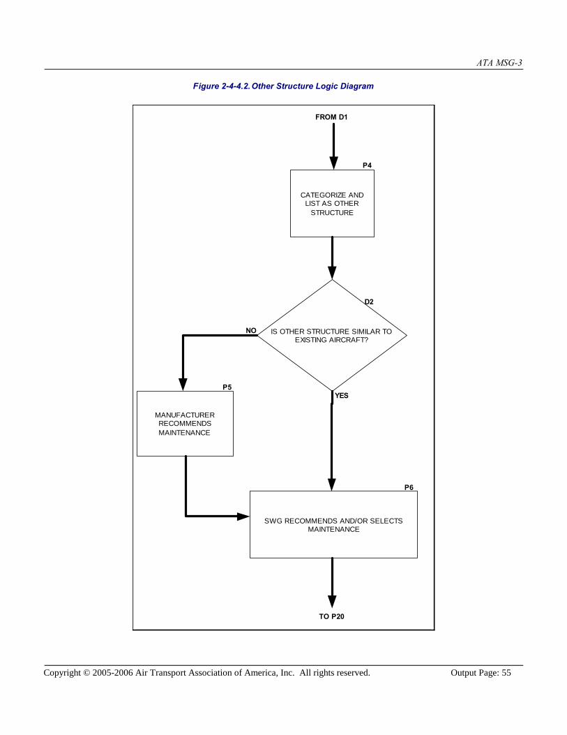
ATA MSG-3
Copyright © 2005-2006 Air Transport Association of America, Inc. All rights reserved. Output Page: 55
Figure 2-4-4.2.Other Structure Logic Diagram
FROM D1
CATEGORIZE ANDLIST AS OTHER
STRUCTURE
MANUFACTURERRECOMMENDSMAINTENANCE
SWG RECOMMENDS AND/OR SELECTSMAINTENANCE
TO P20
IS OTHER STRUCTURE SIMILAR TOEXISTING AIRCRAFT?
P4
YES
NO
P5
D2
P6
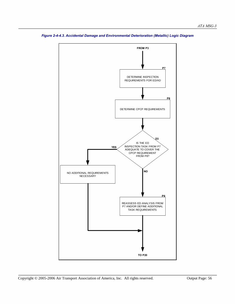
ATA MSG-3
Copyright © 2005-2006 Air Transport Association of America, Inc. All rights reserved. Output Page: 56
Figure 2-4-4.3. Accidental Damage and Environmental Deterioration (Metallic) Logic Diagram
FROM P3
DETERMINE INSPECTIONREQUIREMENTS FOR ED/AD
DETERMINE CPCP REQUIREMENTS
NO ADDITIONAL REQUIREMENTSNECESSARY
REASSESS ED ANALYSIS FROMP7 AND/OR DEFINE ADDITIONAL
TASK REQUIREMENTS
TO P20
IS THE EDINSPECTION TASK FROM P7ADEQUATE TO COVER THE
CPCP REQUIREMENTFROM P8?
YES
NO
P9
D3
P8
P7

ATA MSG-3
Copyright © 2005-2006 Air Transport Association of America, Inc. All rights reserved. Output Page: 57
Figure 2-4-4.4.Accidental Damage and Environmental Deterioration (Non-Metallic) Logic Diagram
FROM P3
SSI SENSITIVE TOAD?
DETERMINE LIKELIHOOD OFMULTIPLE OCCURRENCE
DETERMINE AD IMPACT ON EDANALYSIS
DETERMINE SSI SENSITIVITYTO STRUCTURAL
COMPOSITION
DETERMINE SSI SENSITIVITYTO THE ENVIRONMENT
DETERMINE INSPECTIONLEVEL AND INTERVAL
TO P20
D4
NO
YES
P10
P11
P12
P13
P14

ATA MSG-3
Copyright © 2005-2006 Air Transport Association of America, Inc. All rights reserved. Output Page: 58
Figure 2-4-4.5.Safelife Limit Analysis Logic Diagram
FROM D5
CATEGORIZE AND LIST AS SAFE LIFE;MANUFACTURER DETERMINES SAFE LIFE AND
INCLUDES WITH SSI DESCRIPTION IN AIRWORTHINESSLIMITATIONS
TO P19
P15
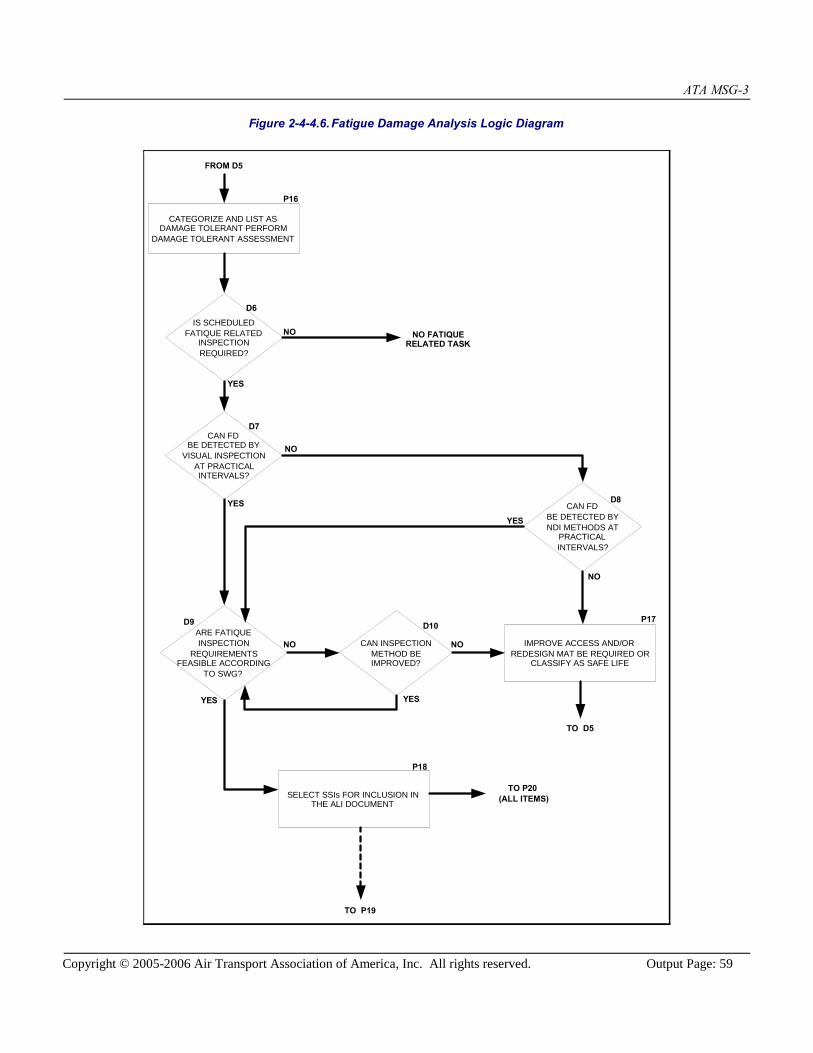
ATA MSG-3
Copyright © 2005-2006 Air Transport Association of America, Inc. All rights reserved. Output Page: 59
Figure 2-4-4.6.Fatigue Damage Analysis Logic Diagram
FROM D5
CATEGORIZE AND LIST ASDAMAGE TOLERANT PERFORM
DAMAGE TOLERANT ASSESSMENT
IMPROVE ACCESS AND/ORREDESIGN MAT BE REQUIRED OR
CLASSIFY AS SAFE LIFE
SELECT SSIs FOR INCLUSION INTHE ALI DOCUMENT
IS SCHEDULEDFATIQUE RELATED
INSPECTIONREQUIRED?
CAN FDBE DETECTED BY
VISUAL INSPECTIONAT PRACTICALINTERVALS?
CAN FDBE DETECTED BYNDI METHODS AT
PRACTICALINTERVALS?
ARE FATIQUEINSPECTION
REQUIREMENTSFEASIBLE ACCORDING
TO SWG?
CAN INSPECTIONMETHOD BEIMPROVED?
TO P19
TO P20(ALL ITEMS)
NO FATIQUERELATED TASK
TO D5
P16
D6
NO
YES
NO
YES
D7
D8
YES
NO
P17
NONO
YES YES
D10D9
P18

ATA MSG-3
Copyright © 2005-2006 Air Transport Association of America, Inc. All rights reserved. Output Page: 60
2-4-5. Rating Systems for Structural Significant Items
As part of the scheduled structural maintenance development, it is necessary to rate each Structural Significant Item in termsof susceptibility (likelihood of damage) and detectability (timely detection of damage). This section provides guidelines toassist manufacturers in the development of suitable rating systems. The rating system should account for the susceptibilityof the SSI to the likely source of damage and the likely type of deterioration of the SSI due to the damage source.Differences between metallic and non-metallic portions of the SSI's must be taken into account.
The scheduled structural maintenance tasks and intervals are developed on the basis of requirements to assure timelydetection of Accidental Damage, Environmental Deterioration, and Fatigue Damage. Rating systems for AD and ED shouldbe compatible to allow comparative assessments for each group of SSIs. Emphasis is placed on rating each SSI in relationto other SSIs in the same inspection area, leading to increased inspection emphasis for the most critical SSIs. Manufacturerand operator experience is a key ingredient for these evaluations.
Rating systems for FD of metals should incorporate results from the manufacturer's residual strength and crack growthevaluations. Where required, rating systems for FD of non-metals should incorporate results from manufacturer's approvedtests. The applicability and effectiveness of various inspection methods, detectable damage sizes and access requirementsare key ingredients for these evaluations.
1. Rating Accidental Damage
Accidental damage rating systems should include evaluations of the following
a. Susceptibility to minor (not obvious) accidental damage based on frequency of exposure to and the location ofdamage from one or more sources, including:
1. Ground handling equipment
2. Cargo handling equipment
3. Those resulting from human error during manufacture, maintenance, and/or operation of the aircraft, that arenot included in other damage sources.
4. Rain, hail, etc.
5. Runway debris
6. Lightning strike
7. Water entrapment
b. Residual strength after accidental damage, normally based on the likely size of damage relative to the criticaldamage size for the SSI.
c. Timely detection of damage, based on the relative rate of growth after damage is sustained and visibility of the SSIfor inspection. Assessments should take into account damage growth associated with non-chemical interaction withan environment, such as disbond or delamination growth associated with a freeze/thaw cycle.
Rating values should be assigned to groups of SSIs in the same inspection area on the basis of comparative assessmentswithin the group.

ATA MSG-3
Copyright © 2005-2006 Air Transport Association of America, Inc. All rights reserved. Output Page: 61
2. Rating Environmental Deterioration (metals)
Environmental deterioration rating systems should allow for evaluations of susceptibility to and timely detection ofcorrosion and stress corrosion.
Susceptibility to corrosion is assessed on the basis of probable exposure to an adverse environment and adequacy of theprotective system. For example:
a. Exposure to a deteriorating environment such as cabin condensation, galley spillage, toilet spillage, cleaning fluids,etc.
b. Contact between dissimilar materials (potential for galvanic activity).
c. Breakdown of surface protection systems; for example, deterioration of paint, primer, bonding, sealant, corrosioninhibiting compounds and cladding systems with the resulting corrosion of metallic materials or fluid incursion intopermeable non-metallic materials, etc.
Material characteristics, coupled with the likelihood of sustained tensile stress, are used to assess susceptibility to stresscorrosion.
Timely detection is determined by sensitivity to relative size of damage and visibility of the SSI for inspection.
NOTE: Rating system evaluations should be made taking into account the requirement for each operator tocontrol the aircraft structure at corrosion Level 1 or better.
3. Rating Environmental Deterioration (non-metals)
Environmental deterioration rating systems should allow for evaluations of susceptibility to, and timely detection of,structural deterioration (e.g., delamination and disbonding).
Susceptibility to deterioration (e.g., loss of stiffness) is assessed on the basis of materials subjected to environmental sourcesand the adequacy of the protective system. For example:
a. Aramind Fiber Reinforced Plastic (AFRP, also known as Kevlar) is sensitive to Ultra-Violet (UV) light, moistureand other fluids, when directly exposed.
b. Glass Fiber Reinforced Plastic (GFRP) may undergo long term degradation when directly exposed to UV light, butotherwise has low sensitivity to the environment.
c. Carbon Fiber Reinforced Plastic (CFRP) has low sensitivity to the environment.
Susceptibility to delamination and disbonding is assessed on the basis of material type, adequacy of the protective system,and structural composition (e.g., honeycomb and solid laminate), coupled with the likelihood of AD, and exposure to certainenvironmental conditions.
4. Rating Fatigue Damage
The rating system must lead to inspections that provides a high probability of detecting fatigue damage in the fleet beforesuch damage reduces any aircraft's residual strength below allowable levels. To achieve this, the rating system should

ATA MSG-3
Copyright © 2005-2006 Air Transport Association of America, Inc. All rights reserved. Output Page: 62
consider the following:
a. Residual strength, including the effects of multiple site fatigue damage, where appropriate.
b. Crack growth rate, including effects of multiple site or multiple element fatigue damage, where appropriate.
c. Damage detection period which corresponds to the interval for the fatigue damage to grow from the threshold ofdetection (detectable) to the limiting size defined by "a" (critical). This period will vary according to the inspectionmethod used, and may be influenced by structural parts or processes, e.g., sealant obscuring parts of the damage.
d. Detection standards for applicable inspection methods.
NOTE: Estimated detectable crack lengths can be used for the fatigue damage detection evaluations required aspart of aircraft type certification.
e. Applicable inspection levels and methods (e.g., visual, NDI), directions (e.g., external, internal) and repeat intervals(e.g., C, 2C, 4C).

ATA MSG-3
Copyright © 2005-2006 Air Transport Association of America, Inc. All rights reserved. Output Page: 63
2-5. Zonal Analysis Procedure
Zonal inspections may be developed from application of the Zonal Analysis Procedure. This requires a summary review ofeach zone on the aircraft and normally occurs as the MSG-3 analyses of structures, systems, and powerplants are beingconcluded. These inspections may subsequently be included in the Zonal Inspections.
This Zonal Analysis Procedure permits appropriate attention to be given to electrical wiring installations. Thus, as well asdetermining zonal inspections, the logic provides a means to identify applicable and effective tasks to minimizecontamination and to address significant wiring installation discrepancies that may not be reliably detected through zonalinspection. These dedicated tasks may subsequently be included in the Systems and Powerplant tasks.
In top down analyses conducted under MSG-3, many support items such as plumbing, ducting, Other Structure, wiring, etc.,may be evaluated for possible contribution to functional failure. In cases where a general visual inspection is required toassess degradation, the zonal inspection is an appropriate method.
2-5-1. ProcedureThe following procedures may be used
a. Divide the aircraft externally and internally into zones as defined in [ATA iSpec 2200], (formerly ATA Spec 100).
b. For each zone, prepare a work sheet that identifies data such as: zone location and access, approximate size(volume), type of systems and components installed, typical power levels in any wiring bundles, features specific toL/HIRF protection, etc. In addition, assess potential for the presence of combustible material, either throughcontamination (e.g., dust and lint) or occurring by design (e.g., fuel vapor).
c. Develop rating tables to determine the repeat interval for a zonal inspection. Rating tables will permit thelikelihood of accidental damage, environmental deterioration and the density of equipment in the zone to be takeninto account.
d. For all zones containing systems installations, perform a standard zonal analysis using the rating tables fromparagraph (c.) to define the extent and interval of zonal inspection tasks. Multiple zonal inspections may beidentified for each zone with those having less frequent intervals requiring increased access requirements.
e. Identify zones that both contain electrical wiring and have potential for combustible material being present. Forthose zones, perform an enhanced zonal analysis that permits the identification of stand-alone inspection tasks thatallow appropriate attention to be given to deterioration of installed wiring and electrical wiring interconnectionsystem (EWIS), in particular for wiring in close proximity (i.e., within 2 inches or 50 mm) to both primary andback-up hydraulic, mechanical, or electrical flight controls, and tasks that minimize contamination by combustiblematerials, if applicable and effective. Rating tables addressing the potential effects of fire caused by awiring/EWIS failure on adjacent wiring and systems (e.g., the risk to aircraft controllability), the size of the zoneand the density of installed equipment may be used to determine the inspection level. General Visual Inspectionsmay be found effective for the complete zone. Detailed Inspections may be found applicable and effective forspecific items in a zone. Interval determination may be accomplished using rating tables that consider accidentaldamage and environment.
f. Detailed Inspections, stand-alone GVIs, and tasks to minimize contamination, arising from paragraph "e" should beincluded in the Systems and Powerplant tasks. Since these tasks are not specific to the routine ATA-definedsystems and do not have a Failure Effect Category, introduction in a dedicated section is suggested, for example,under ATA 20.

ATA MSG-3
Copyright © 2005-2006 Air Transport Association of America, Inc. All rights reserved. Output Page: 64
g. General Visual Inspections arising from the enhanced zonal analysis (paragraph e.) may be compared with theZonal Inspections determined from the standard zonal analysis (paragraph d.). The former may be considered fullycovered by the zonal inspection if the access requirement is the same and the proposed interval is at least asfrequent. Otherwise, a stand-alone GVI should be included with the tasks identified in paragraph (f.).
h. General Visual Inspections arising from the systems, powerplants and structures may be compared with the ZonalInspections determined from the standard zonal analysis (paragraph d.). Work sheets should record the intervalproposed in the originating analysis. These GVIs may be considered fully covered by the zonal inspection if theaccess requirement is the same and the proposed interval is at least as frequent. Otherwise, a stand-alone GVIshould be included within the MSI or SSI from which it was identified.
i. General Visual Inspections arising from the analysis of L/HIRF may be compared with the Zonal Inspectionsdetermined from the standard zonal analysis (paragraph d.). These GVIs may be considered fully covered by thezonal inspection if the access requirement is the same and the proposed interval is at least as frequent. Otherwise, astand-alone GVI should be included within the Systems and Powerplants tasks as described in [Subject 2-6-1].
j. Visual Checks may be considered covered by the Zonal Inspections provided that the Systems Working Group thatidentified them consider that the failure would be noted and addressed during a zonal inspection. Otherwise, thetask should remain in the Systems and Powerplants tasks where specific attention can be drawn to the item.
k. All tasks developed through application of the standard zonal analysis (paragraph d.) should be included in theZonal Inspections. For accountability purposes, any General Visual Inspection or Visual Check originating fromapplication of systems, powerplant or structures analyses should be referenced in the MRB Report zonal task. Toavoid giving unjustified attention to these items, this should not be indicated on task/work cards.
l. All EZAP-derived stand-alone tasks (GVI or DET) should be uniquely identified in the data documentation fortraceability during future changes. This is intended to prevent the inadvertent deletion or escalation of anEZAP-derived stand-alone task without proper consideration of the risk basis for the task and its interval.
A typical logic diagram is depicted in [Figure 2-5-1.1] and [Figure 2-5-1.2]. This is provided as a guide and may becustomized to reflect individual company policies and procedures.

ATA MSG-3
Copyright © 2005-2006 Air Transport Association of America, Inc. All rights reserved. Output Page: 65
Figure 2-5-1.1.Typical Zonal Analysis Procedure
Prepare A/C Zoning,including boundaries
List details of Zone, e.g.:-- Access-- Installed Equipment-- L/HIRF protection
features-- Wire bundle installation-- Possible combustible
materials in zone-- etc.
Zone contains onlyStructure?
Zone containsWiring?
Zonal Analysisnecessary?
No Task
Perform Zonal Analysis; e.g.,Rating Table:
-- AD-- Environment-- Density
Define interval and accessrequirements
Consider candidatesfrom System &
Powerplant, L/HIRF,and Structure
Analysis Procedures
Wiring inspection task determination
Inspection level definition.Inspection level verification.
Interval determination.
Combustiblematerials in zone?
Is there aneffective task to significantly
reduce the likelihood ofaccumulation of combustible
materials?
Define Task and Interval
MRB ReportSystem and Powerplant Section
MRB ReportZonal Section
Task Consolidation?
and/or
and/or
YES
NO
NO
YES
NOYES
NO
YES
YES
NO
DET GVI
Continue analysisStand-alone
See Figure 2-5-1.2
ENHANCED ZONAL ANALYSIS
STANDARD ZONAL ANALYSIS
Wiring portion
Is wiringclose to both
primary & back-uphydraulic, mechanical,
or electricalflight
controls?
NO
YES
Non-wiring portion
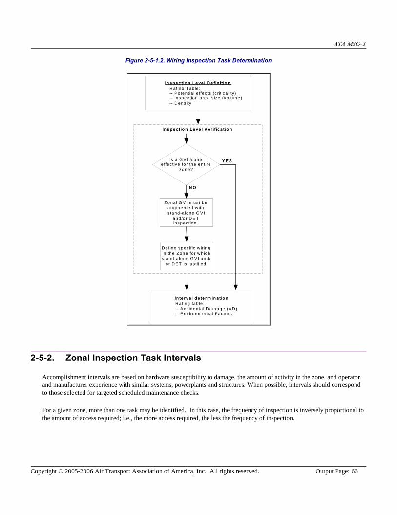
ATA MSG-3
Copyright © 2005-2006 Air Transport Association of America, Inc. All rights reserved. Output Page: 66
Figure 2-5-1.2. Wiring Inspection Task Determination
Inspection Level D e fin itionR ating Tab le :-- Potentia l e ffects (c ritica lity)-- Inspec tion area s ize (vo lum e)-- D ens ity
Is a G VI a loneeffec tive for the entire
zone?
Zona l G V I m ust beaugm ented w iths tand-a lone G V I
and/o r D E Tinspec tion .
In terval determ inationR ating tab le :-- A cc identa l D am age (A D )-- E nvironm enta l Fac tors
Y ES
N O
Inspection Level V erification
D efine specific w iringin the Zone for w h ichstand-a lone G V I and/
or D E T is jus tified
2-5-2. Zonal Inspection Task Intervals
Accomplishment intervals are based on hardware susceptibility to damage, the amount of activity in the zone, and operatorand manufacturer experience with similar systems, powerplants and structures. When possible, intervals should correspondto those selected for targeted scheduled maintenance checks.
For a given zone, more than one task may be identified. In this case, the frequency of inspection is inversely proportional tothe amount of access required; i.e., the more access required, the less the frequency of inspection.
ATA MSG-3
Copyright © 2005-2006 Air Transport Association of America, Inc. All rights reserved. Output Page: 67
2-6. Lightning/High Intensity Radiated Field (L/HIRF) AnalysisProcedure
Lightning/High Intensity Radiated Field (L/HIRF) protection systems have been identified for development of dedicatedmaintenance. The intent of this maintenance is to reduce the possibility that a single failure cause (such as a lightningstrike), and the occurrence of a common failure cause (such as ED or AD) across redundant channels of L/HIRF protection,could impact aircraft airworthiness.
This section contains guidelines for development of scheduled maintenance tasks for aircraft L/HIRF protection systems.Each L/HIRF protective system item is evaluated in terms of its susceptibility to degradation from environmentaldeterioration and/or accidental damage. The L/HIRF protection system maintenance tasks are developed in support of theaircraft type certification and MRB report development.
Using a logic type analysis, the Working Group determines the type of scheduled maintenance task that is both applicableand effective along with the frequency (interval) of the task.
Lightning/High Intensity Radiated Field (L/HIRF) protection is rated for its criticality with respect to the consequences ofthe protection's failure.
L/HIRF maintenance is divided into two (2) distinct categories:
1. L/HIRF Protection within LRUs (contained in the Component Maintenance Manual, CMM). L/HIRF protectionfeatures are incorporated inside the LRU. Protection devices such as filter pin connectors, discrete filter capacitorsand transient protection devices (tranzorbs) are installed within LRUs on one or more of the LRU interface circuits.
The aircraft manufacturer will work with the suppliers of LRUs requiring L/HIRF protection to ensure that theCMM states the Supplier's maintenance philosophy to ensure the continued effectiveness of L/HIRF protectivedevices. The maintenance of this type of L/HIRF protection is not developed with the use of this document.
2. L/HIRF Protection on the aircraft (developed during this MSG-3 process, and contained in the subsequent MRBReport).All Level A and B L/HIRF protection on the aircraft (any protection not within an LRU) that was identified duringL/HIRF certification must be analyzed. Normally this includes items such as shielded wires, raceways, bondingjumpers, connectors, composite fairings with conductive mesh, and the inherent conductivity of the structure, butmay include aircraft specific devices, e.g., RF Gaskets.
Level A systems are electrical and electronic systems whose failure would cause or contribute to a failure offunction resulting in a catastrophic-failure condition of the aircraft.
Level B systems are electrical and electronic systems whose failure would cause or contribute to a failure offunction resulting in a hazardous-failure condition of the aircraft.

ATA MSG-3
Copyright © 2005-2006 Air Transport Association of America, Inc. All rights reserved. Output Page: 68
2-6-1. L/HIRF Maintenance
The scheduled maintenance must cover all identified L/HIRF protection. The majority of this protection will be coveredthrough the Zonal Inspections. Where this Zonal maintenance will not adequately identify degradation of the L/HIRFprotection, additional scheduled maintenance may be generated.
1. L/HIRF Protection Analysis Focus
In order to narrow the focus of the analysis, the following concepts are accepted:
1. All visible L/HIRF protection (wires, shields, connectors, bonding straps, or raceways between connectors ortermination points) may be covered by the Zonal Inspections.
2. L/HIRF protection within conduit or heatshrink, is covered in the Zonal Inspections by confirming integrity of theprotective covering.
3. Inherent conductivity of the aircraft structure is covered by the Zonal Inspections. Corrosion concerns areaddressed by the Structural Inspections.
4. Composite fairings with conductive mesh are covered by the Zonal Inspections.
5. Where the Zonal Inspections are not effective, additional analysis may produce other scheduled maintenance tasks.
2. L/HIRF Protection Analysis Ratings
L/HIRF protections require an analysis for the effects of Environmental Deterioration (ED) and Accidental Damage (AD) todetermine what maintenance will effectively detect degradation.
Environment - consider the effects of the atmosphere, corrosive products, condensation, temperature, and vibration onthe protection, with respect to degradation.
Susceptibility to Damage - consider the likelihood of damage during maintenance or damage during operations.Examples would be areas where connectors could be stepped on, or effects of de-icing fluid on a connector duringwinter operations.
3. Analysis Approval
Once the analysis is completed, the resulting maintenance tasks and intervals for all L/HIRF systems are submitted to theISC for approval and inclusion in the MRB Report proposal.
4. Flowchart Description
The following is the intent of each block of the flow chart that follows:
Block 1 - "Aircraft L/HIRF Protective Systems"Self-explanatory; flow diagram "Title" block.
Block 2 - "Define Aircraft Zones"Prior to accomplishment of L/HIRF analysis, it is necessary to have the Zones defined.
Block 3 - "Define Level A and B"

ATA MSG-3
Copyright © 2005-2006 Air Transport Association of America, Inc. All rights reserved. Output Page: 69
Defining what systems are Level A or Level B is a separate process from MSG-3, and is usually derived from aseparate engineering report
Block 4 - Is it a Level A or B?"Analysis for Level A will follow a separate flow path from Level B.
Block 5 - "Determine Inspection"L/HIRF analysis will use an ED/AD assessment to determine task and interval for L/HIRF protection maintenance.
Block 6 - "Are Zonal Inspection Tasks Applicable and Effective?"Wherever possible, credit will be taken for Zonal Inspections.
Block 7 - "Covered by Zonal Maintenance"Assessment shows the Zonal Inspections are effective.
Block 8 - "Is Protection Similar?"Is it possible to take credit for similar protection that has been evaluated to be effective on similar type aircraft?
Block 9 - "Manufacturer's Maintenance"If there is no similar protection installed on another aircraft, the manufacturer can choose its own method for taskdetermination on Level B systems.
Block 10 - Working Group Recommendations"Incorporation of the Working Group's recommendations.
Block 11 - "L/HIRF Maintenance"All tasks roll into the L/HIRF Maintenance.
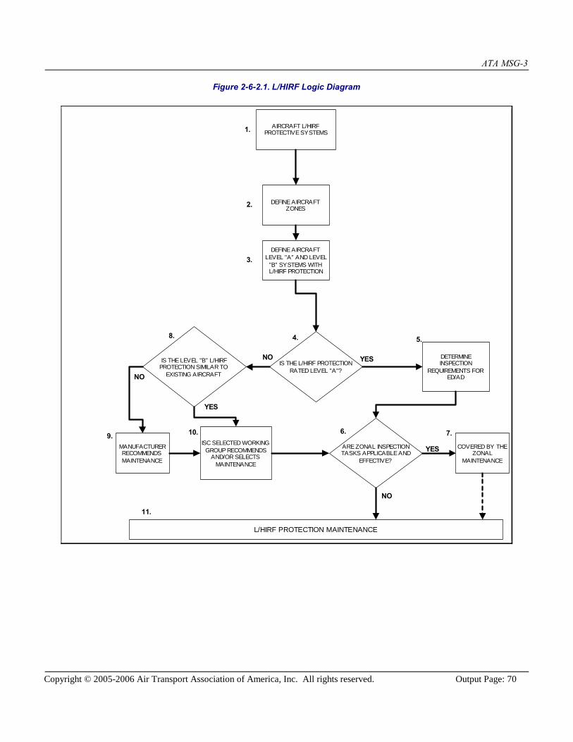
ATA MSG-3
Copyright © 2005-2006 Air Transport Association of America, Inc. All rights reserved. Output Page: 70
Figure 2-6-2.1. L/HIRF Logic Diagram
AIRCRAFT L/HIRFPROTECTIVE SYSTEMS
DEFINE AIRCRAFTZONES
DEFINE AIRCRAFTLEVEL "A" AND LEVEL
"B" SYSTEMS WITHL/HIRF PROTECTION
IS THE L/HIRF PROTECTIONRATED LEVEL "A"?
DETERMINEINSPECTION
REQUIREMENTS FORED/AD
IS THE LEVEL "B" L/HIRFPROTECTION SIMILAR TO
EXISTING AIRCRAFT
MANUFACTURERRECOMMENDSMAINTENANCE
ISC SELECTED WORKINGGROUP RECOMMENDS
AND/OR SELECTSMAINTENANCE
ARE ZONAL INSPECTIONTASKS APPLICABLE AND
EFFECTIVE?
COVERED BY THEZONAL
MAINTENANCE
L/HIRF PROTECTION MAINTENANCE
1.
2.
3.
4.
NO YES
5.
7.
YES
NO
6.
8.
9. 10.
11.
YES
NO

ATA MSG-3
Copyright © 2005-2006 Air Transport Association of America, Inc. All rights reserved. Output Page: 71
Appendix A. Glossary
Accidental Damage (AD) Physical deterioration of an item caused by contact or impact with an objector influence which is not a part of the aircraft, or by human error duringmanufacturing, operation of the aircraft, or maintenance practices.
Age Exploration A systematic evaluation of an item based on analysis of collected informationfrom in-service experience. It verifies the item's resistance to a deteriorationprocess with respect to increasing age.
Airworthiness Limitations A section of the Instructions for Continued Airworthiness that contains eachmandatory replacement time, structural inspection interval, and relatedstructural inspection task. This section may also be used to define a thresholdfor the fatigue related inspections and the need to control corrosion to Level 1or better. The information contained in the Airworthiness Limitations sectionmay be changed to reflect service and/or test experience or new analysismethods.
Conditional Probability of Failure The probability that a failure will occur in a specific period provided that theitem concerned has survived to the beginning of that period.
Corrosion Level 1 Corrosion damage that does not require structural reinforcement orreplacement.orCorrosion occurring between successive inspections exceeds allowable limitbut is local and can be attributed to an event not typical of operator usage ofother aircraft in the same fleet (e.g. Mercury spill).
Corrosion Prevention and Control Program (CPCP) A program of maintenance tasks implemented at a threshold designed tocontrol an aircraft structure to Corrosion Level 1 or better.
Damage Tolerant A qualification standard for aircraft structure. An item is judged to bedamage tolerant if it can sustain damage and the remaining structure canwithstand reasonable loads without structural failure or excessive structuraldeformation until the damage is detected.
Delamination/Disbond Structural separation or cracking that occurs at or in the bond plane of astructural element, within a structural assembly, caused by in serviceaccidental damage, environmental effects and/or cyclic loading.
Direct Adverse Effect on Operating Safety
Direct To be direct, the functional failure or resulting secondary damage mustachieve its effect by itself, not in combination with other functional failures(no redundancy exists and it is a primary dispatch item).
Adverse Effect on Safety Safety shall be considered as adversely affected if the consequences of thefailure condition would prevent the continued safe flight and landing of theaircraft and/or might cause serious or fatal injury to human occupants.
Operating This is defined as the time interval during which passengers and crew are onboard for the purpose of flight.
Discard The removal from service of an item at a specified life limit.

ATA MSG-3
Copyright © 2005-2006 Air Transport Association of America, Inc. All rights reserved. Output Page: 72
Economic Effects Failure effects which do not prevent aircraft operation, but are economicallyundesirable due to added labor and material cost for aircraft or shop repair.
Electrical Wiring Interconnection System (EWIS) An electrical connection between two or more points including the associatedterminal devices (e.g., connectors, terminal blocks, splices) and the necessarymeans for its installation and identification.
Environmental Deterioration (ED) Physical deterioration of an item's strength or resistance to failure as a resultof chemical interaction with its climate or environment.
Failure The inability of an item to perform within previously specified limits.
Failure Cause Why the functional failure occurs.
Failure Condition The effect on the aircraft and its occupants, both direct and consequential,caused or contributed to by one or more failures, considering relevant adverseoperational or environmental conditions.
Failure Effect What is the result of a functional failure?
Fatigue Damage (FD) The initiation of a crack or cracks due to cyclic loading and subsequentpropagation.
Fatigue Related Sampling Inspection Inspections on specific aircraft selected from those which have the highestoperating age/usage in order to identify the first evidence of deterioration intheir condition caused by fatigue damage.
Fault An identifiable condition in which one element of a redundant system hasfailed (no longer available) without impact on the required function output ofthe system (MSI). At the system level, a fault is not considered a functionalfailure.
Fault-Tolerant System A system that is designed with redundant elements that can fail withoutimpact on safety or operating capability.
Function The normal characteristic actions of an item.
Functional Check A quantitative check to determine if one or more functions of an itemperforms within specified limits.
Functional Failure Failure of an item to perform its intended function within specified limits.
Hidden Function 1. A function which is normally active and whose cessation will not beevident to the operating crew during performance of normal duties.2. A function which is normally inactive and whose readiness to perform,prior to it being needed, will not be evident to the operating crew duringperformance of normal duties.
Inherent Level of Reliability and Safety That level which is built into the unit and, therefore, inherent in its design.This is the highest level of reliability and safety that can be expected from aunit, system, or aircraft if it receives effective maintenance to achieve higherlevels of reliability generally requires modification or redesign.
Inspection - Detailed (DET) An intensive examination of a specific item, installation or assembly to detectdamage, failure or irregularity. Available lighting is normally supplementedwith a direct source of good lighting at an intensity deemed appropriate.
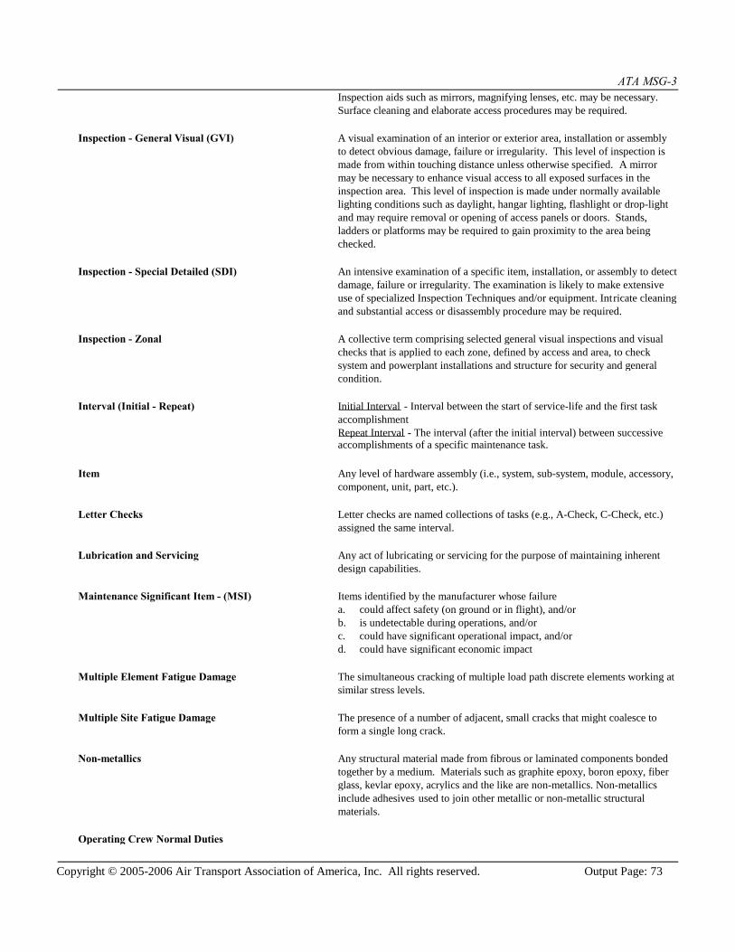
ATA MSG-3
Copyright © 2005-2006 Air Transport Association of America, Inc. All rights reserved. Output Page: 73
Inspection aids such as mirrors, magnifying lenses, etc. may be necessary.Surface cleaning and elaborate access procedures may be required.
Inspection - General Visual (GVI) A visual examination of an interior or exterior area, installation or assemblyto detect obvious damage, failure or irregularity. This level of inspection ismade from within touching distance unless otherwise specified. A mirrormay be necessary to enhance visual access to all exposed surfaces in theinspection area. This level of inspection is made under normally availablelighting conditions such as daylight, hangar lighting, flashlight or drop-lightand may require removal or opening of access panels or doors. Stands,ladders or platforms may be required to gain proximity to the area beingchecked.
Inspection - Special Detailed (SDI) An intensive examination of a specific item, installation, or assembly to detectdamage, failure or irregularity. The examination is likely to make extensiveuse of specialized Inspection Techniques and/or equipment. Intricate cleaningand substantial access or disassembly procedure may be required.
Inspection - Zonal A collective term comprising selected general visual inspections and visualchecks that is applied to each zone, defined by access and area, to checksystem and powerplant installations and structure for security and generalcondition.
Interval (Initial - Repeat) Initial Interval - Interval between the start of service-life and the first taskaccomplishmentRepeat Interval - The interval (after the initial interval) between successiveaccomplishments of a specific maintenance task.
Item Any level of hardware assembly (i.e., system, sub-system, module, accessory,component, unit, part, etc.).
Letter Checks Letter checks are named collections of tasks (e.g., A-Check, C-Check, etc.)assigned the same interval.
Lubrication and Servicing Any act of lubricating or servicing for the purpose of maintaining inherentdesign capabilities.
Maintenance Significant Item - (MSI) Items identified by the manufacturer whose failurea. could affect safety (on ground or in flight), and/orb. is undetectable during operations, and/orc. could have significant operational impact, and/ord. could have significant economic impact
Multiple Element Fatigue Damage The simultaneous cracking of multiple load path discrete elements working atsimilar stress levels.
Multiple Site Fatigue Damage The presence of a number of adjacent, small cracks that might coalesce toform a single long crack.
Non-metallics Any structural material made from fibrous or laminated components bondedtogether by a medium. Materials such as graphite epoxy, boron epoxy, fiberglass, kevlar epoxy, acrylics and the like are non-metallics. Non-metallicsinclude adhesives used to join other metallic or non-metallic structuralmaterials.
Operating Crew Normal Duties

ATA MSG-3
Copyright © 2005-2006 Air Transport Association of America, Inc. All rights reserved. Output Page: 74
Operating Crew Qualified flight compartment and cabin attendant personnel who are on duty.
Normal Duties Those duties associated with the routine operation of the aircraft, on a dailybasis, to include the fol lowing:a. Procedures and checks performed during aircraft operation inaccordance with the Aircraft Flight Manual.b. Recognition of abnormalities or failures by the operating crew throughthe use of normal physical senses (e.g., odor, noise, vibration, temperature,visual observation of damage or failure, changes in physical input forcerequirements, etc.).
Operational Check An operational check is a task to determine that an item is fulfilling itsintended purpose. Does not require quantitative tolerances. This is a failurefinding task.
Operational Effects Failure effects which interfere with the completion of the aircraft mission.These failures cause delays, cancellations, ground or flight interruptions, highdrag coefficients, altitude restrictions, etc.
Other Structure Structure which is judged not to be a Structural Significant Item."Other Structure" is defined both externally and internally within zonalboundaries.
Potential Failure A defined identifiable condition that indicates that a degradation process istaking place that will lead to a functional failure.
Protective Device Any device or system that has a function to avoid, eliminate or reduce theconsequences of an event or the failure of some other function.
P to F Interval Interval between the point at which a potential failure becomes detectable andthe point at which it degrades into a functional failure.
Redundant Functional Elements Two or more independent physical elements of a system/item providing thesame function.
Residual Strength The strength of a damaged structure.
Restoration That work necessary to return the item to a specific standard. Restorationmay vary from cleaning or replacement of single parts up to a completeoverhaul.
Safe Life Structure Structure which is not practical to design or qualify as damage tolerant. Itsreliability is protected by discard limits which remove items from servicebefore fatigue cracking is expected.
Safety (adverse effect) Safety shall be considered as adversely affected if the consequences of thefailure condition would prevent the continued safe flight and landing of theaircraft and/or might cause serious or fatal injury to human occupants.
Safety/Emergency Systems or Equipment A device or system that:
1) enhances the evacuation of the aircraft in an emergency or,
2) if it does not function when required, results in a Failure Condition thatmight have an adverse effect on safety.

ATA MSG-3
Copyright © 2005-2006 Air Transport Association of America, Inc. All rights reserved. Output Page: 75
Scheduled Maintenance Check Any of the maintenance opportunities which are prepackaged and areaccomplished on a regular basis.
Structural Significant Item - (SSI) Any detail, element or assembly, which contributes significantly to carryingflight, ground, pressure or control loads and whose failure could affect thestructural integrity necessary for the safety of the aircraft.
Structural Assembly One or more structural elements which together provide a basic structuralfunction.
Structural Detail The lowest functional level in an aircraft structure. A discrete region or areaof a structural element, or a boundary intersection of two or more elements.
Structural Element Two or more structural details which together form an identifiedmanufacturer's assembly part.
Structural Function The mode of action of aircraft structure. It includes acceptance and transferof specified loads in items (details /elements /assemblies) and providesconsistently adequate aircraft response and flight characteristics.
Task Applicability A set of conditions that leads to the identification of a task type when aspecific set of characteristics of the failure cause being analyzed would bediscovered and/or corrected as a result of the task being accomplished.
Task Effectiveness A specific set of conditions that leads to the selection of a task alreadyidentified to be applicable. Avoids, eliminates, or reduces the negativeconsequences of the failure to an extent that justifies doing the task at theselected interval.
Tasks - Maintenance An action or set of actions required to achieve a desired outcome whichrestores an item to or maintains an item in serviceable condition, includinginspection and determination of condition.
Threshold See "Interval - Initial".
Threshold Period A period during which no occurrences of the failure can reasonably beexpected to occur after the item enters into service.
Visual Check A visual check is an observation to determine that an item is fulfilling itsintended purpose. Does not require quantitative tolerances. This is a failurefinding task.

ATA MSG-3
Copyright © 2005-2006 Air Transport Association of America, Inc. All rights reserved. Output Page: 76
Annex 1. References
[ATA iSpec 2200] ATA Specification 2200. Information Standards for Aviation Maintenance. Air TransportAssociation (www.airlines.org), Washington, DC.
ATA MSG-3
Copyright © 2005-2006 Air Transport Association of America, Inc. All rights reserved. Output Page: 77
Endnotes1 (Popup - QuickAccess)
[Clear]Display all:
FiguresTablesReferencesRevisions:
In Condensed ModeIn Full ContextIn Full Specification
Deprecated Areas