mt-200cc, mt-400cc & mt-400ccehd* gun - esab... · aws c5.5 - "recommended practices for...
TRANSCRIPT
INSTRUCTIONS for F-15-085-CApril, 1998
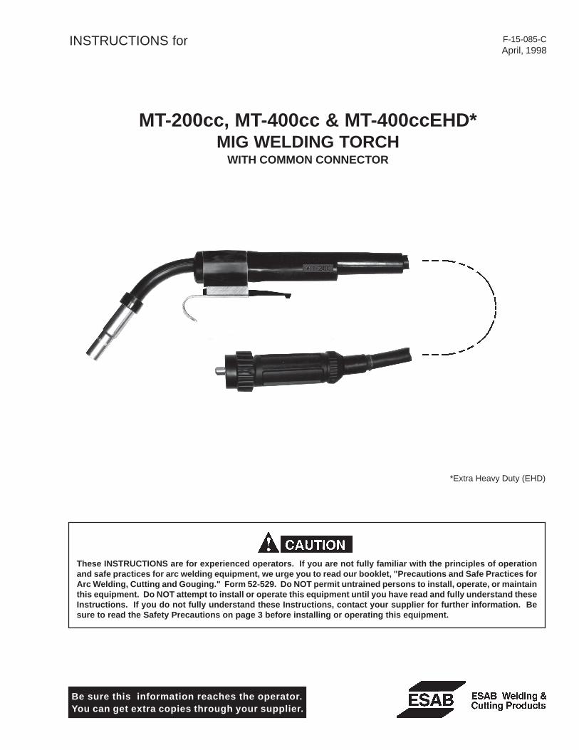
MT-200cc, MT-400cc & MT-400ccEHD*MIG WELDING TORCH
WITH COMMON CONNECTOR
Be sure this information reaches the operator.You can get extra copies through your supplier.
These INSTRUCTIONS are for experienced operators. If you are not fully familiar with the principles of operationand safe practices for arc welding equipment, we urge you to read our booklet, "Precautions and Safe Practices forArc Welding, Cutting and Gouging." Form 52-529. Do NOT permit untrained persons to install, operate, or maintainthis equipment. Do NOT attempt to install or operate this equipment until you have read and fully understand theseInstructions. If you do not fully understand these Instructions, contact your supplier for further information. Besure to read the Safety Precautions on page 3 before installing or operating this equipment.
*Extra Heavy Duty (EHD)

2
��������������
������������� ����������������������� ����������������������������������������������������������������������������������������� ������������������������������������������������������������� ������������������������������������������������������������������������������������������������������������������������������������������������� ������������������������������������������������������������ �������������������������������������������������������������������������������������������� �����������������������������������������������!������"���#��������������� ������������
������������������������������������������������������ ���������������� ��������������������������������������������������������������������������������������������������������������� ������������������������������������������������������������������������������������������������������������������������������������������������������������������������
����������������
�� ����������� ���������������������������������������������������������������������������������������������������������� ��� � �������������������������������������������������������������������������������������������������������������������� ��� ���������������������������������������������������������������������������������������������������������������� ���� ������� !"����#��� ������������������������������������������������������������������������������������������ ���$ ��� %!& �����'!(�� �!)!��*� ���� ������������������������������������������������������������������� �
��� ����&++&���� ������������������������������������������������������������������������������������������������������������ ,��� ��� %!���� ����� ��������������������������������������������������������������������������������������������� ,����� &��-��*� !.� �*� ��������������������������������������������������������������������������������������������� ,
���� �/"�&��������������������������������������������������������������������������������������������������������������������� ,��� ��������0!�����'!/�� ������� ���������������������������������������������������������������������������� ,��� /��-1�* !�������#���� ������������������������������������������������������������������������������������ 2��� 1�* ��0!/�� � ���� ������������������������������������������������������������������������������������������ 2��$ �%�� �3�!/�� � ��� ����������������������������������������������������������������������������������������� 2
4 �"�4�" ���������������������������������������������������������������������������������������������������������������������� 2$�� ���5� �!/�� � ��� ��������������������������������������������������������������������������������������������� 2$�� ����� �!�� !���5� �!��� %!��0�*��*' ��������������������������������������������������������������� �6$�� ��77*�� ������������������������������������������������������������������������������������������������������������ �6$�$ 1���!��� !+����!8�9 ���!6�6��-���!*����: ���������������������������������������������������������� �6$� 6�6��-���!1���!��� !+���� �������������������������������������������������������������������������������� ��$�� ��5� !1���!(�� � ������������������������������������������������������������������������������������������ ��$�; ��� %!�3�� % ���������������������������������������������������������������������������������������������������� ��$�, <�� *�!�� !�=*�!&���#=*' ���������������������������������������������������������������������������� ��
4� �"/+&"."��!/&��� �������������������������������������������������������������������������������������������� ��

3
WARNING: These Safety Precautions are foryour protection. They summarize precaution-ary information from the references listed inAdditional Safety Information section. Before
performing any installation or operating procedures, besure to read and follow the safety precautions listed belowas well as all other manuals, material safety data sheets,labels, etc. Failure to observe Safety Precautions can resultin injury or death.
PROTECT YOURSELF AND OTHERS --Some welding, cutting, and gougingprocesses are noisy and require earprotection. The arc, like the sun, emitsultraviolet (UV) and other radiation and
can injure skin and eyes. Hot metal can cause burns.Training in the proper use of the processes and equip-ment is essential to prevent accidents. Therefore:
1. Always wear safety glasses with side shields in any workarea, even if welding helmets, face shields, and gogglesare also required.
2. Use a face shield fitted with the correct filter and coverplates to protect your eyes, face, neck, and ears fromsparks and rays of the arc when operating or observingoperations. Warn bystanders not to watch the arc andnot to expose themselves to the rays of the electric-arcor hot metal.
3. Wear flameproof gauntlet type gloves, heavy long-sleeveshirt, cuffless trousers, high-topped shoes, and a weld-ing helmet or cap for hair protection, to protect againstarc rays and hot sparks or hot metal. A flameproof apronmay also be desirable as protection against radiatedheat and sparks.
4. Hot sparks or metal can lodge in rolled up sleeves,trouser cuffs, or pockets. Sleeves and collars should bekept buttoned, and open pockets eliminated from thefront of clothing
5. Protect other personnel from arc rays and hot sparkswith a suitable non-flammable partition or curtains.
6. Use goggles over safety glasses when chipping slag orgrinding. Chipped slag may be hot and can fly far.Bystanders should also wear goggles over safety glasses.
FIRES AND EXPLOSIONS -- Heat fromflames and arcs can start fires. Hot slagor sparks can also cause fires and ex-plosions. Therefore:
1. Remove all combustible materials well away from thework area or cover the materials with a protective non-flammable covering. Combustible materials include wood,cloth, sawdust, liquid and gas fuels, solvents, paints andcoatings, paper, etc.
2. Hot sparks or hot metal can fall through cracks orcrevices in floors or wall openings and cause a hiddensmoldering fire or fires on the floor below. Make certainthat such openings are protected from hot sparks andmetal.“
3. Do not weld, cut or perform other hot work until theworkpiece has been completely cleaned so that thereare no substances on the workpiece which might pro-duce flammable or toxic vapors. Do not do hot work onclosed containers. They may explode.
4. Have fire extinguishing equipment handy for instant use,such as a garden hose, water pail, sand bucket, orportable fire extinguisher. Be sure you are trained in itsuse.
SAFETY PRECAUTIONS
11/95
5. Do not use equipment beyond its ratings. For example,overloaded welding cable can overheat and create a firehazard.
6. After completing operations, inspect the work area tomake certain there are no hot sparks or hot metal whichcould cause a later fire. Use fire watchers when neces-sary.
7. For additional information, refer to NFPA Standard 51B,"Fire Prevention in Use of Cutting and Welding Pro-cesses", available from the National Fire Protection Asso-ciation, Batterymarch Park, Quincy, MA 02269.
ELECTRICAL SHOCK -- Contact with liveelectrical parts and ground can causesevere injury or death. DO NOT use ACwelding current in damp areas, if move-ment is confined, or if there is danger offalling.
1. Be sure the power source frame (chassis) is connectedto the ground system of the input power.
2. Connect the workpiece to a good electrical ground.3. Connect the work cable to the workpiece. A poor or
missing connection can expose you or others to a fatalshock.
4. Use well-maintained equipment. Replace worn or dam-aged cables.
5. Keep everything dry, including clothing, work area, cables,torch/electrode holder, and power source.
6. Make sure that all parts of your body are insulated fromwork and from ground.
7. Do not stand directly on metal or the earth while workingin tight quarters or a damp area; stand on dry boards oran insulating platform and wear rubber-soled shoes.
8. Put on dry, hole-free gloves before turning on the power.9. Turn off the power before removing your gloves.
10. Refer to ANSI/ASC Standard Z49.1 (listed on next page)for specific grounding recommendations. Do not mistakethe work lead for a ground cable.
ELECTRIC AND MAGNETIC FIELDS —May be dangerous. Electric current flow-ing through any conductor causes lo-calized Electric and Magnetic Fields(EMF). Welding and cutting current cre-ates EMF around welding cables andwelding machines. Therefore:
1. Welders having pacemakers should consult their physi-cian before welding. EMF may interfere with some pace-makers.
2. Exposure to EMF may have other health effects which areunknown.
3. Welders should use the following procedures to minimizeexposure to EMF:A. Route the electrode and work cables together. Secure
them with tape when possible.B. Never coil the torch or work cable around your body.C. Do not place your body between the torch and work
cables. Route cables on the same side of your body.�� ������������ ������������ ��������������
������������������������������ ��������������������������������� �������
�����������������������

4
FUMES AND GASES -- Fumes andgases, can cause discomfort or harm,particularly in confined spaces. Donot breathe fumes and gases. Shield-ing gases can cause asphyxiation.Therefore:
1. Always provide adequate ventilation in the work area bynatural or mechanical means. Do not weld, cut, or gougeon materials such as galvanized steel, stainless steel,copper, zinc, lead, beryllium, or cadmium unless positivemechanical ventilation is provided. Do not breathe fumesfrom these materials.
2. Do not operate near degreasing and spraying opera-tions. The heat or arc rays can react with chlorinatedhydrocarbon vapors to form phosgene, a highly toxicgas, and other irritant gases.
3. If you develop momentary eye, nose, or throat irritationwhile operating, this is an indication that ventilation is notadequate. Stop work and take necessary steps to im-prove ventilation in the work area. Do not continue tooperate if physical discomfort persists.
4. Refer to ANSI/ASC Standard Z49.1 (see listing below)for specific ventilation recommendations.
CYLINDER HANDLING -- Cylinders, ifmishandled, can rupture and violentlyrelease gas. Sudden rupture of cylin-der, valve, or relief device can injure orkill. Therefore:
1. Use the proper gas for the process and use the properpressure reducing regulator designed to operate fromthe compressed gas cylinder. Do not use adaptors.Maintain hoses and fittings in good condition. Followmanufacturer's operating instructions for mounting regu-lator to a compressed gas cylinder.
2. Always secure cylinders in an upright position by chainor strap to suitable hand trucks, undercarriages, benches,walls, post, or racks. Never secure cylinders to worktables or fixtures where they may become part of anelectrical circuit.
3. When not in use, keep cylinder valves closed. Havevalve protection cap in place if regulator is not con-nected. Secure and move cylinders by using suitablehand trucks. Avoid rough handling of cylinders.
4. Locate cylinders away from heat, sparks, and flames.Never strike an arc on a cylinder.
5. For additional information, refer to CGA Standard P-1,"Precautions for Safe Handling of Compressed Gases inCylinders", which is available from Compressed GasAssociation, 1235 Jefferson Davis Highway, Arlington,VA 22202.
EQUIPMENT MAINTENANCE -- Faulty or im-properly maintained equipment can causeinjury or death. Therefore:
1. Always have qualified personnel perform the installa-tion, troubleshooting, and maintenance work. Do not
perform any electrical work unless you are qualified toperform such work.
2. Before performing any maintenance work inside a powersource, disconnect the power source from the incomingelectrical power.
3. Maintain cables, grounding wire, connections, powercord, and power supply in safe working order. Do notoperate any equipment in faulty condition.
4. Do not abuse any equipment or accessories. Keepequipment away from heat sources such as furnaces,wet conditions such as water puddles, oil or grease,corrosive atmospheres and inclement weather.
5. Keep all safety devices and cabinet covers in positionand in good repair.
6. Use equipment only for its intended purpose. Do notmodify it in any manner.
ADDITIONAL SAFETY INFORMATION -- Formore information on safe practices for elec-tric arc welding and cutting equipment, askyour supplier for a copy of "Precautions andSafe Practices for Arc Welding, Cutting andGouging", Form 52-529.
The following publications, which are available from theAmerican Welding Society, 550 N.W. LeJuene Road, Mi-ami, FL 33126, are recommended to you:1. ANSI/ASC Z49.1 - "Safety in Welding and Cutting"2. AWS C5.1 - "Recommended Practices for Plasma Arc
Welding"3. AWS C5.2 - "Recommended Practices for Plasma Arc
Cutting"4. AWS C5.3 - "Recommended Practices for Air Carbon
Arc Gouging and Cutting"5. AWS C5.5 - "Recommended Practices for Gas Tungsten
Arc Welding“6. AWS C5.6 - "Recommended Practices for Gas Metal Arc
Welding"“7. AWS SP - "Safe Practices" - Reprint, Welding Hand-
book.8. ANSI/AWS F4.1, "Recommended Safe Practices for
Welding and Cutting of Containers That Have HeldHazardous Substances."
This symbol appearing throughout this manualmeans Attention! Be Alert! Your safety isinvolved.
The following definitions apply to DANGER, WARNING,CAUTION found throughout this manual:
Used to call attention to immediate haz-ards which, if not avoided, will result inimmediate, serious personal injury or lossof life.
Used to call attention to potential haz-ards which could result in personal injuryor loss of life.
Used to call attention to hazards whichcould result in minor personal injury.
5
I. INTRODUCTION
1.1 SCOPE
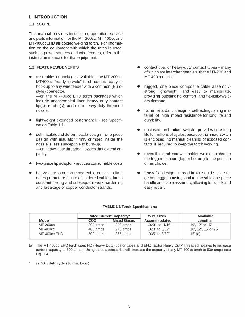
This manual provides installation, operation, serviceand parts information for the MT-200cc, MT-400cc andMT-400ccEHD air-cooled welding torch. For informa-tion on the equipment with which the torch is used,such as power sources and wire feeders, refer to theinstruction manuals for that equipment.
1.2 FEATURES/BENEFITS
� assembles or packages available - the MT-200cc,MT400cc "ready-to-weld" torch comes ready tohook up to any wire feeder with a common (Euro-style) connector.—or, the MT-400cc EHD torch packages whichinclude unassembled liner, heavy duty contacttip(s) or tube(s), and extra-heavy duty threadednozzle.
� lightweight extended performance - see Specifi-cation Table 1.1.
� self-insulated slide-on nozzle design - one piecedesign with insulator firmly crimped inside thenozzle is less susceptible to burn-up.—or, heavy-duty threaded nozzles that extend ca-pacity.
� two-piece tip adaptor - reduces consumable costs
� heavy duty torque crimped cable design - elimi-nates premature failure of soldered cables due toconstant flexing and subsequent work hardeningand breakage of copper conductor strands.
TABLE 1.1 Torch Specifications
(a) The MT-400cc EHD torch uses HD (Heavy Duty) tips or tubes and EHD (Extra Heavy Duty) threaded nozzles to increasecurrent capacity to 500 amps. Using these accessories will increase the capacity of any MT-400cc torch to 500 amps (seeFig. 1.4).
* @ 60% duty cycle (10 min. base)
Rated Current Capacity* Wire Sizes AvailableModel CO2 Mixed Gases Accommodated LengthsMT-200cc 300 amps 200 amps .023" to 1/16" 10', 12' or 15'MT-400cc 400 amps 275 amps .023" to 3/32" 10', 12', 15' or 25'MT-400cc EHD 500 amps 375 amps .035" to 3/32" 15' (a)
� contact tips, or heavy-duty contact tubes - manyof which are interchangeable with the MT-200 andMT-400 models.
� rugged, one piece composite cable assembly-strong lightweight and easy to manipulate,providing outstanding comfort and flexibility weld-ers demand.
� flame retardant design - self-extinguishing ma-terial of high impact resistance for long life anddurability.
� enclosed torch micro-switch - provides sure longlife for millions of cycles; because the micro-switchis enclosed, no manual cleaning of exposed con-tacts is required to keep the torch working.
� reversible torch screw - enables weldier to changethe trigger location (top or bottom) to the positionof his choice.
� "easy fix" design - thread-in wire guide, slide to-gether trigger housing, and replaceable one-piecehandle and cable assembly, allowing for quick andeasy repair.

6
TABLE 1.2 Basic Torch Assemblies Available (see Fig. 5.1)*
* Basic torches do not include liners, contact tips/tubes, or nozzles. Mix and match the accessories listed in Fig. 1.4 andTables 1.4.1, 1.4.2, and 1.4.3 to customize a torch for your welding application.
Heavy Duty Tips, Tubes and Nozzles improve the per-formance and extend the service life when used withhigh current applications, high spatter wires, pulsed arcmig and when used in confined areas.
Extra Heavy Duty (brass) Slide-on Nozzles provideimproved service life when subjected to extreme im-pact abuse.
Extra Heavy Duty Threaded Nozzles and Heavy DutyTips and Tubes extend the rating of the MT-400cc from400 amps to 500 amps @ 60% duty cycle.
Accessory Selection - Assembly Guide .. see Fig. 1.4Contact Tips and Tubes .................... see Table 1.4.1Nozzles (slip-on or threaded) ............ see Table 1.4.2Liners ............................................... see Table 1.4.3
1.3 REQUIRED EQUIPMENT
WIRE FEEDERThe MT-200cc and MT-400cc torch connects to anywire feeder equipped with a common (or Euro) styleconnector. This quick-disconnect style connector in-cludes power/wire, gas supply and trigger circuit con-nections. The required wire feeder accessories, whichinclude feed rolls and wire outlet guides, are shown inthe power source/wire feeder instruction booklet.
1.4 TORCH ACCESSORY GUIDE & SELECTION -Fig. 1.4, & Tables 1.4.1, 1.4.2 and 1.4.3.
Standard Duty Tips and Nozzles provide good perfor-mance and service life for the majority of welding ap-plications.
Basic Assy./Length 10-ft. (3.0m) 12-ft. (3.6m) 15-ft. (4.5m) 25-ft. (7.5m)MT-200cc 21091 21092 21093 ---MT-400cc 21138 21139 21140 21141
Figure 1.4 Accessories Selection - Assembly Guide
To select correct accessories, choose tip based on wire and follow Guide Chart to determine nozzle and adaptors.
CONTACT TIPSAND TUBES
STANDARD DUTY CONTACT TIPS
ADAPTORSNOZZLES
SLIDE ON SELF INSULATED NOZZLES
MT-200cc
MT-400cc
STANDARD DUTY
SEE TABLE1.4.1
FOR PARTNUMBERS
.023" M or L .052" S or M
.030" M or L 1/16" S or M
.035" M or L 5/64" S or M
.045" - 3/64" S, M or L
SHORT (S)
MEDIUM (M)
LONG (L)
SEE TABLE1.4.1
FOR PARTNUMBERS
#6 TAPERED #12#8 #12 SPOT#10
EXTRA HEAVYDUTY
HEAVY DUTY#8#10#12#12 SPOT
#12 BRASS
STANDARD ACCESSORIES
SEE TABLE1.4.2
FOR PARTNUMBERS
HEAVY DUTY CONTACT TIPS EXTRA HEAVY DUTYTHREADED NOZZLESSHORT (S)
MEDIUM (M)
.045" - 3/64" M 1/16" M
.052"M 5/64" M 3/32" M
SEE TABLE1.4.1
FOR PARTNUMBERS
HEAVY DUTY CONTACT TUBES
SHORT (S)
MEDIUM (M)
.035" M 1/16" M
.045" - 3/64" M 5/64" S
.052" M 3/32" S
SEE TABLE1.4.2
FOR PARTNUMBERS
#8#10#12#16 SPOT
P/N 948785
P/N 17766 (.045" - 1/16")P/N 948786 (5/64" - 3/32")
P/N 17135P/N 17136 P/N 17154
P/N 17318
P/N 948793
COLLET BODY COLLET
PRIMARY USE OF ACCESSORIES ALTERNATE USE OF ACCESSORIES
ACCESSORIES FOR EXTENDED RATING *
NOZZLE ADAPTOR
EXTRA HEAVYDUTY
ADAPTOR
TIP ADAPTOR
TIP ADAPTOR
P/N 17983
P/N 17984
P/N 999452
NOZZLEADAPTOR
* Using Heavy Duty contact tips or tubes and Extra Duty threadednozzles will increase the rated capacity of the MT-400cc to 500 amps.
7
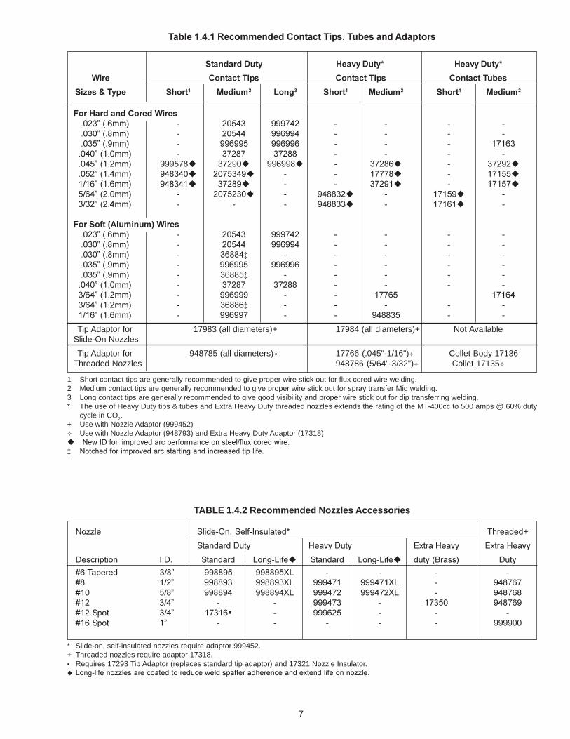
1 Short contact tips are generally recommended to give proper wire stick out for flux cored wire welding.2 Medium contact tips are generally recommended to give proper wire stick out for spray transfer Mig welding.3 Long contact tips are generally recommended to give good visibility and proper wire stick out for dip transferring welding.* The use of Heavy Duty tips & tubes and Extra Heavy Duty threaded nozzles extends the rating of the MT-400cc to 500 amps @ 60% duty
cycle in CO2.+ Use with Nozzle Adaptor (999452)� Use with Nozzle Adaptor (948793) and Extra Heavy Duty Adaptor (17318)�������������� �������� ������������������������������� ������������� ������������������������������� �����
�������������� ��������������������������������������
����������� ��� ���� ��� ����
���� ������������ ������������ ������������
����������� ������ ������ ����� ������ ������ ������ ������
����������������������������� �!��" # ��$%� &&&'%� # # # #����� �(��" # ��$%% &&!&&% # # # #���$� �&��" # &&!&&$ &&!&&! # # # )')!���%�� )����" # �'�(' �'�(( # # # #��%$� )����" &&&$'(� �'�&�� &&!&&(� # �'�(!� # �'�&����$�� )�%��" &%(�%�� ��'$�%&� # # )'''(� # )')$$�)*)!� )�!��" &%(�%)� �'�(&� # # �'�&)� # )')$'�$*!%� �����" # ��'$���� # &%((��� # )')$&� #�*��� ��%��" # # # &%((��� # )')!)� #
������ ��!"#����$����������� �!��" # ��$%� &&&'%� # # # #����� �(��" # ��$%% &&!&&% # # # #����� �(��" # �!((%� # # # # #���$� �&��" # &&!&&$ &&!&&! # # # #���$� �&��" # �!(($� # # # # #��%�� )����" # �'�(' �'�(( # # # #�*!%� )����" # &&!&&& # # )''!$ )')!%�*!%� )����" # �!((!� # # # # #)*)!� )�!��" # &&!&&' # # &%((�$ # #
Tip Adaptor for 17983 (all diameters)+ 17984 (all diameters)+ Not AvailableSlide-On Nozzles
Tip Adaptor for 948785 (all diameters)� 17766 (.045"-1/16")� Collet Body 17136Threaded Nozzles 948786 (5/64"-3/32")� Collet 17135�
TABLE 1.4.2 Recommended Nozzles Accessories
+�,,�� -����#.�/-���#0��������1 2������+
-����������� 3��4����� �5���3��4� �5���3��4�
����������� 0��� -������� 6���#6���� -������� 6���#6���� ���� 7����" ����
8!2������ �*(� &&((&$ &&((&$96 # # # #8( )*�� &&((&� &&((&�96 &&&%') &&&%')96 # &%('!'8)� $*(� &&((&% &&((&%96 &&&%'� &&&%'�96 # &%('!(8)� �*%� # # &&&%'� # )'�$� &%('!&8)�-��� �*%� )'�)!� # &&&!�$ # # #8)!-��� )� # # # # # &&&&��
* Slide-on, self-insulated nozzles require adaptor 999452.+ Threaded nozzles require adaptor 17318.� Requires 17293 Tip Adaptor (replaces standard tip adaptor) and 17321 Nozzle Insulator.� ���������������������������������������� ��������������������������������������

8
b. The radiant energy of the arc can decompose chlo-rinated solvent vapors, such as trichloroethyleneand perchloroethylene, to form phosgene, evenwhen these vapors are present in low concentra-tions. Do NOT weld where chlorinated solventsare present in atmospheres in or around the arc.
c. Do NOT touch the electrode, contact tip or metalparts in contact with them when power is ON; allare electrically energized (HOT) and can cause apossibly fatal shock. DO NOT allow electrode totouch grounded metal; it will create an arc flashthat can injure eyes. It may also start a fire orcause other damage.
d. When working in a confined space, be sure it issafe to enter. The confined space should be testedfor adequate oxygen (at least 19%) with an ap-proved oxygen measuring instrument. The con-fined space should not contain toxic concentrationsof fumes or gases. If this cannot be determined,the operator should wear an approved air suppliedbreathing apparatus.
Avoid gas leaks in a confined space, as the leakedgas can dangerously reduce oxygen concentra-tion in the breathing air.
DO NOT bring gas cylinders to confined spaces.
When leaving a confined space, shut OFF gassupply at the source to prevent gas from leakinginto the space. Check the breathing atmospherein the confined space to be sure it is safe to reen-ter.
e. Never operate the equipment at currents greaterthan the rated ampere capacity; over-heating willoccur.
II. INSTALLATION
2.1 TORCH CONNECTIONS
2.1.1 AIR-COOLED MODELS
a. Install appropriate guide tube in wire feeder priorto mounting torch. On wire feeders equipped withquick-disconnect torch adapter, line up service andtrigger pins, insert and tighten retaining collar. (SeeTable for guide tube part numbers in wire feederinstruction booklet.)
b. The MT-200cc torch is supplied with liner and con-tact tip for particular wire size and No. 8 nozzleinstalled. If desiring to change these componentsfor another wire size as given in Table 1.4, refer tothe Maintenance section for instructions.
NOTEThe MT-200cc is rated to operate up to 300 ampsusing CO2; 200 amps using mixed gases (60% dutycycle).
III. OPERATION
3.1 OPERATING SAFETY PRECAUTIONS
Comply with all ventilation, fire and other safety require-ments for arc welding as established in the SAFETYSection at the front of this manual.
Comply, also, with the following precautions:
a. Whenever welding above 250 amps, a No. 14 fil-ter lens should be worn on your protective helmet.Up to 250 amps, No. 11 or 12 filter lens is recom-mended.
Wire Liner
Size & Type 10' 12' 15' 25'Hard Wires & Cored Wires.023" (.6mm) 999743* 34929* - -.030" (.8mm) 948850 17717 - -.035" (.9mm) 2075237 17718 2075238 18235.045" (1.2mm) 2075237 17718 2075238 18235.052" (1.4mm) 2075239 17719 2075240 182361/16" (1.6mm) 2075239 17719 2085240 182365/64" (2.0mm) 2075245 17720 2075246 -3/32" (2.4mm) 2075245+ 17720 2075246 -Soft Wires (aluminum).035" (.9mm) 948862 33931 - -3/64" (1.2mm) 948863 34932 - -1/16" (1.6mm) 19065** - - -
TABLE 1.4.3 Recommended Liners Accessories
* Requires support liner for .023" wire. Order P/N 999797 for 10 ft. or P/N 34930 for 12 ft.** Requires Support Liner, P/N 34930.+ 45° curved wire guide (P/N 18243) recommended for 3/32" wire.

9
f. Never operate equipment in damp, wet or confinedareas without suitable insulation for protectionagainst shock. Keep hands, feet and clothing dryat all times.
g. Whenever the equipment is left unattended, turnall control and power source switches and gas sup-plies OFF and open the main line switch.
h. Wear dark substantial clothing to protect exposedskin from arc burn, sparks and flying hot metal.
i. Turn off welding power before adjusting or replac-ing electrodes, contact tips, nozzles, or contact tipadaptors.
3.2 PRE-WELD REQUIREMENTS
Before welding, refer to feeder manual for pre-weldrequirements and checklist. Also check that:
a. Correct size liner, guide tube, contact tip and nozzleare installed and uncontaminated by dirt or spat-ter.
b. Wire is properly threaded through gun.
c. Nozzle is free from excessive spatter.
If all pre-weld requirements have been met for feederand torch, turn on all required power controls and pro-ceed to weld.
IMPORTANTFor argon shield gas applications, copper nozzlesshould be used in place of brass nozzles.
When the POWER is ON, and torch trigger is de-pressed, the electrode wire becomes electricallyHOT. Do NOT touch the wire as it may cause apossibly fatal shock. Do NOT allow wire to touchgrounded metal surfaces other than the work tobe welded.
3.3 WELDING PROCEDURE
a. On each new application, weld trial pieces of simi-lar metal to determine any necessary welding ad-justments.
b. When the trigger is squeezed, weld wire feedscontinuously into the arc and the resulting weldpuddle is protected by the shielding gas. Protectthe arc from strong drafts which can disrupt shield-ing gas coverage and cause porous welds.
NOTECorrect torch position, and coating of an anti-spat-ter compound on all torch surfaces exposed tospatter, reduces spatter accumulation.
IMPORTANTKeep hoses, and cables from touching hot metal.Do not lay torch down on hot metal.
c. To stop the arc, release the trigger.
NOTERelease the trigger, pull torch away from work onlyfar enough to prevent welding wire from freezingin weld puddle. Gas will continue to flow for a shortperiod.
d. When putting torch down, comply with (Step c) andCAUTION in next paragraph.
IMPORTANTNever use torch as a hammer to remove spatter.
3.4 SHUTDOWN PROCEDURE
When welding is completed, shut down the equipmentas follows:a. Shut OFF all power controls.b. Turn off gas at source.c. Place torch in safe location.
Do not allow protruding welding wire to touch agrounded metal surface.
d. Coil or drape hose and cable without sharp bends.
IV. SERVICE
4.1 SERVICE PROCEDURE
Always shut OFF all power and gas supplies be-fore attempting inspection, maintenance, or repairunless otherwise instructed here. Remove mainline fuses or lock and red tag switches.If power source is ON, electrode wire becomes elec-trically HOT when gun trigger is pressed, and driverolls start. Keep fingers clear of drive rolls. DoNOT touch wire or metal parts contacting it or al-low wire to touch grounded metal. It may causepossibly fatal shock, fire or other damage. (SeeOperating Safety Precautions in preceding section,item 3.1).

10
grounded metal, it would create an arc flash. If itshould touch the body, it could cause a fatal shock.
d. Periodically remove any weld spatter or foreignmatter which has accumulated around the nozzleorifice and contact tip. To ease spatter removal,spray a thin film of anti-spatter compound on con-tact tip and nozzle before welding and reapply thecompound after cleaning of tip and nozzle.
e. Replace contact tip if worn.
f. Remove any accumulation around trigger that maymake it stick, or cause short circuits.
To avoid shock, do not depress trigger while han-dling contact tip or nozzle parts or while disassem-bling torch.
4.3 NOZZLESIMPORTANT
Do not hammer torch or nozzle to remove spatter.
Spatter can be removed from the inside of the nozzlewith a hand reamer or file. Adherence of spatter canbe minimized and removal made easier by coating theinside of the nozzle with No. 65 Nozzle Anti-SpatterCompound.
4.4 WIRE FEED LINER (Except 0.023-in liner, seeSection 4.4)
To remove liner for cleaning or replacement, proceedas follows:
1. Remove nozzle, contact tip, tip adaptor and frontinsulator.
2. Loosen the setscrew in the curved wire guide andremove the liner retaining nut (21073) from thecentral adaptor block (21067), and then lay thetorch cable out relatively straight.
3. Push on the liner extending from the front end ofthe torch. You should then be able to grab the endof the liner at the adaptor block by hand and pull itout of the torch keeping the cable relatively straightwhile pulling.
4. Be sure to wear proper eye and face protection.Blow out metallic chips, grit, etc. from the liner andthe handle and cable assembly with compressedair.
NOTE: Direct the initial blast of air away from theparts to clear moisture that occasionally ac-cumulates in compressed air lines.
Equipment which is not functioning properly should notbe used until all required repairs have been completedand the equipment has been tested to ascertain that itis in proper operating condition.
Inspection, troubleshooting, and repair of this equip-ment as indicated in this manual may ordinarily be un-dertaken by a competent person having at least gen-eral experience in the maintenance and repair of equip-ment of this nature.
No such maintenance or repair should ever be un-dertaken by anyone not having such qualifications.
It is recommended that worn parts be replaced withparts manufactured and sold by ESAB Welding & Cut-ting Products.
Except for inspection, troubleshooting, and repairs in-dicated in this manual, it is recommended that all otherservicing be done by an authorized service facility.Contact the Distributor from whom purchased for as-sistance.
If so advised, the unit should be sent to the authorizedservice facility, adequately packaged, in the originalshipping container, if possible, and shipped prepaid,with a statement of the observed deficiency. Returntransportation charges are to be paid by Buyer. In allcases other than when warranty is applicable, repairswill be made at current list price for the replacementpart(s) plus a reasonable labor charge.
4.2 INSPECT AND SERVICE TORCH REGULARLY
a. Clean accumulated dirt from all areas, particularlyelectrical parts where metallic particles can causeshort circuits. Blow out liner with compressed airwhen changing wire. Compressed air should NOTexceed 30 psig (2.1 bar).
b. Tighten loose hardware including all gas and elec-trical connections. (Loose power connections over-heat during welding).
c. Regularly inspect insulation on equipment for pos-sible damage or wear. Check for frayed andcracked insulation. Before using equipment again,make necessary repairs or replace all worn or dam-aged insulation, hoses, cables, conduit, and con-nectors.
With any repairs, make sure that metallic parts donot protrude from insulation. Damaged insulationcan expose the conductor. If it should touch

11
5. Inspect the small gas sealing O-ring (646988) onthe adaptor block. Replace it if damaged. Makesure the O-ring is properly located in the groove.
6. Remove all burrs from the O.D. of the liner's barespring end (particularly if installing a new liner) toprevent snagging while pushing the liner throughthe cable.
7. With the torch cable laying straight, insert the bareend of the liner into the adaptor body. Then pushthe liner slowly through the cable. To prevent pos-sible kinking of the liner, it is recommended to pushit in no more than 150 mm (6-in.) at a time. Anoccasional slight whip-snapping of the inlet flexsupport will also facilitate liner installation as illus-trated below.
b. Remove any sharp burrs on end (O.D. and I.D.)of the spring liner. Burrs could cause wire tobind during the feeding or the liner to sag dur-ing reinstallation into the torch.
SETSCREW
5-6 MM(3/16" - 1/4")
8. After seating the liner ferrule against the adaptorblock, reassemble liner retaining nut to the adap-tor block and tighten firmly with a wrench.
9. If installing a used liner, it should extend beyondthe end of the curved wire guide 3/8 to 7/16-in (9to 11mm). If short rotate the torch handle in thecounter clockwise direction as illustrated below(white arrow) to force the liner to extend more. Ifliner is extending excessively, then rotate thehandle in the clockwise direction (dark arrow).
10. If installing a new replacement liner, it should beextending several inches past the curved wireguide. Proceed as follows:
a. Snip off excess liner with a sharp cutting toolso that the liner extends 3/16-in. to 1/4-in.(5-6mm) from the face of the nozzle adaptor.
11. Install tip adaptor wrench tight to seat the liner.Then tighten the setscrew in the curved wire guidewith the supplied 5/64-in. (2mm) hex key. Do NOTovertighten.
12. Install and tighten proper size contact tip with apair of pliers.
13. Install push-on nozzle. A slight rotating motion willhelp slide the nozzle past the friction rings and O-ring.
4.5 0.023-IN. WIRE FEED LINERS
To install liner and support liners into the torch, use thefollowing procedure (refer to Figure 4.4).
1. Remove nozzle, contact tip, tip adaptor (998869)and front insulator (999474). Back out setscrewin wire guide until it is flush with wire guideO.D. (This setscrew must remain in wire guide toprevent loss of shielding gas.)
2. Remove Liner Retaining Nut (21073), this nut willbe replaced with a different retaining nut (21119),later in the procedure.
3. Lay torch out straight and insert support liner(999797) from inlet end of torch. Seat liner endfitting firmly into torch inlet.
4. Snip off excess support liner protruding from wireguide so that it is flush with end of wire guide.
5. Remove the support liner and cut off an additional1/2-in. (13mm). Deburr and reinstall in torch. Atthis point, you may need to screw-on the new re-taining nut (21119) to temporarily hold the supportliner in place.
12
INNER LINEREND FITTING
TORCHWIRE GUIDE
DO NOT TIGHTENTHIS SETSCREW
INNER LINER
SUPPORT LINER
1/2"
5/16"
SUPPORTLINER
LINERRETAININGNUT
INNER LINER
ADAPTOR BLOCK
ADAPTORSUPPORT BODY
LINER RECEPTACLE ADAPTOR NUT
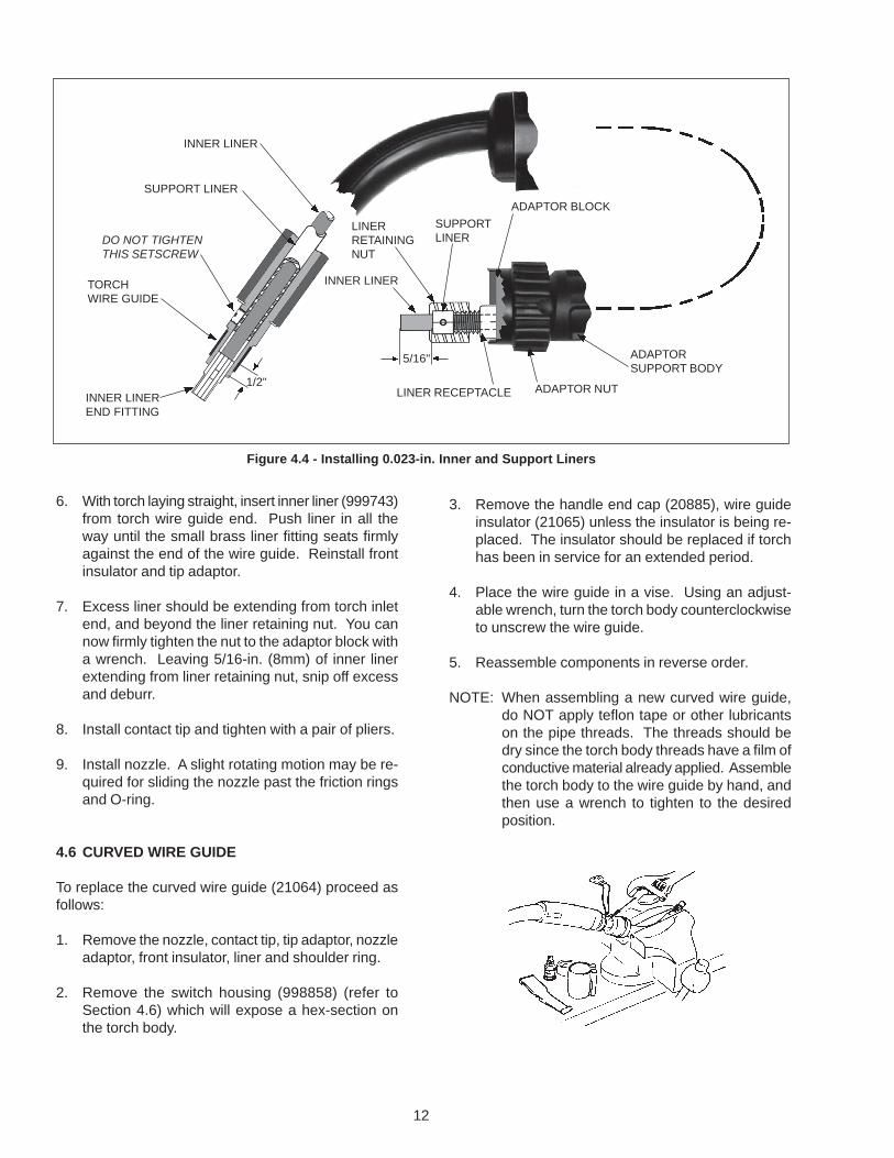
Figure 4.4 - Installing 0.023-in. Inner and Support Liners
6. With torch laying straight, insert inner liner (999743)from torch wire guide end. Push liner in all theway until the small brass liner fitting seats firmlyagainst the end of the wire guide. Reinstall frontinsulator and tip adaptor.
7. Excess liner should be extending from torch inletend, and beyond the liner retaining nut. You cannow firmly tighten the nut to the adaptor block witha wrench. Leaving 5/16-in. (8mm) of inner linerextending from liner retaining nut, snip off excessand deburr.
8. Install contact tip and tighten with a pair of pliers.
9. Install nozzle. A slight rotating motion may be re-quired for sliding the nozzle past the friction ringsand O-ring.
4.6 CURVED WIRE GUIDE
To replace the curved wire guide (21064) proceed asfollows:
1. Remove the nozzle, contact tip, tip adaptor, nozzleadaptor, front insulator, liner and shoulder ring.
2. Remove the switch housing (998858) (refer toSection 4.6) which will expose a hex-section onthe torch body.
3. Remove the handle end cap (20885), wire guideinsulator (21065) unless the insulator is being re-placed. The insulator should be replaced if torchhas been in service for an extended period.
4. Place the wire guide in a vise. Using an adjust-able wrench, turn the torch body counterclockwiseto unscrew the wire guide.
5. Reassemble components in reverse order.
NOTE: When assembling a new curved wire guide,do NOT apply teflon tape or other lubricantson the pipe threads. The threads should bedry since the torch body threads have a film ofconductive material already applied. Assemblethe torch body to the wire guide by hand, andthen use a wrench to tighten to the desiredposition.
13
4.8 HANDLE AND CABLE ASSEMBLY (See Figure5.1)
The handle and cable assembly includes the powercable switch leads, and gas and wire passages. Theouter jacket should be examined periodically for signsof minor damage which may be repaired by the cus-tomer. If severe damage occurs, causing torch mal-functions, the handle and cable assembly should bereplaced.
V. REPLACEMENT PARTS
5.1 GENERAL
All replacement parts are keyed in figure 5.1. Otherreplacement parts by part number and part name. Donot order by part number alone.
The following illustrations of the equipment identify eachreplacement part by part number, description and quan-tity used (in parentheses, if more than one).
Some assemblies are available as a unit or as indi-vidual parts. These parts are listed below such as-semblies. When any of the assembly parts is a subas-sembly, its individual parts are listed below it, indentedanother space.
Attaching hardware items are listed below the part theyattach. They may not be shown. Order them sepa-rately.
5.2 ORDERING
To assure proper operation, it is recommended thatonly genuine ESAB parts be used with this equipment.To order replacement parts:
a. Give the part number, description and quantity ofeach part required.
b. Give part number and description of equipment onwhich the parts are to be used.
c. Indicate any special shipping instructions.
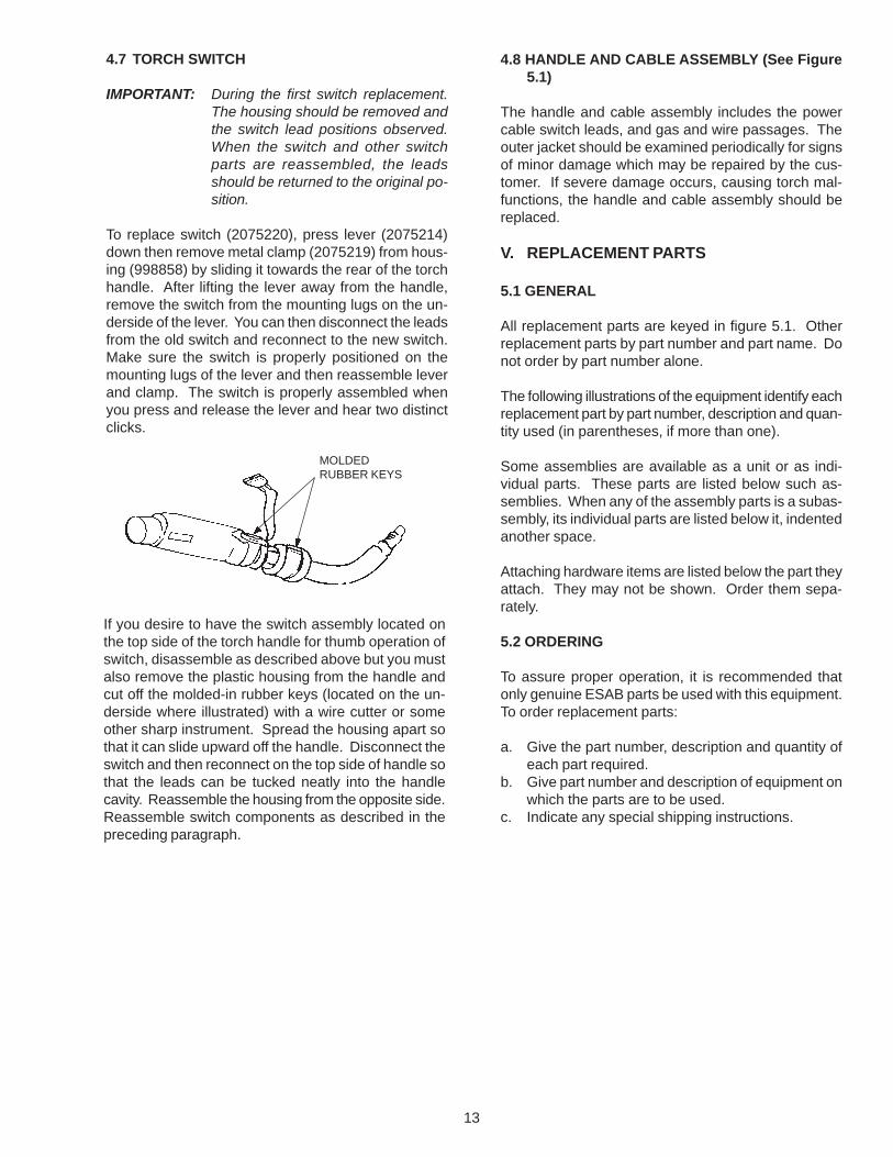
4.7 TORCH SWITCH
IMPORTANT: During the first switch replacement.The housing should be removed andthe switch lead positions observed.When the switch and other switchparts are reassembled, the leadsshould be returned to the original po-sition.
To replace switch (2075220), press lever (2075214)down then remove metal clamp (2075219) from hous-ing (998858) by sliding it towards the rear of the torchhandle. After lifting the lever away from the handle,remove the switch from the mounting lugs on the un-derside of the lever. You can then disconnect the leadsfrom the old switch and reconnect to the new switch.Make sure the switch is properly positioned on themounting lugs of the lever and then reassemble leverand clamp. The switch is properly assembled whenyou press and release the lever and hear two distinctclicks.
MOLDEDRUBBER KEYS
If you desire to have the switch assembly located onthe top side of the torch handle for thumb operation ofswitch, disassemble as described above but you mustalso remove the plastic housing from the handle andcut off the molded-in rubber keys (located on the un-derside where illustrated) with a wire cutter or someother sharp instrument. Spread the housing apart sothat it can slide upward off the handle. Disconnect theswitch and then reconnect on the top side of handle sothat the leads can be tucked neatly into the handlecavity. Reassemble the housing from the opposite side.Reassemble switch components as described in thepreceding paragraph.

14
Fig
. 5.1
- R
epla
cem
ent P
arts
- M
T-20
0cc
& M
T-40
0cc
Bas
ic T
orch
Ass
embl
ies
** D
enot
es It
ems
Not
Incl
uded
With
Bas
ic T
orch
1
1110
9
21A
**
21B
**
22 *
*
23 *
*
1615
14
13
12
3
17
19
20
9A
6
5
47
18

15
Replacement Parts List for Figure 5.
ITEM QTY. PARTNO. REQ'D. NO. DESCRIPTION
1 1 Handle and Cable Assembly:21094 10-Ft., MT-200 (includes Handle 20829 and Cable 21097)21095 12-Ft., MT-200 (includes Handle 20829 and Cable 21098)21096 15-Ft., MT-200 (includes Handle 20829 and Cable 21099)21142 10-Ft., MT-400 (includes Handle 20948 and Cable 21146)21143 12-Ft., MT-400 (includes Handle 20948 and Cable 21147)21144 15-Ft., MT-400 (includes Handle 20948 and Cable 21148)21145 25-Ft., MT-400 (includes Handle 20948 and Cable 21149)
3 1 2062294 Terminal, Supplied in Pkg. of 10(included with Item 1)
4 1 951880 Central Adaptor Block(Includes 2-female wire connectors,Item 5 & 6)
5 1 21073 Liner Retaining Nut (see Item 4)*6 1 18406 O-Ring (see Item 4)7 1 21074 Adaptor Support Screw9 1 21069 Adaptor Support9A 1 21068 Adaptor Nut10 1 21070 Bayonet Ring11 1 21071 Cable Support Sleeve12 1 998858 Switch Housing, MT-200
1 2075745 Switch Housing, MT-40013 1 20885 End Cap, MT-200
1 2075215 End Cap, MT-40014 1 21065 Wire Guide Insulator, MT-200
1 999475 Wire Guide Insulator, MT-40015 1 185W31 Shoulder Ring16 1 21064 Curved Wire Guide, MT-200 (Includes #8-32 x 3/16"
Setscrew & a supplied (5/64" Hex Key)1 18234 Curved Wire Guide, MT-400 (Includes #8-32 x 3/16"
Setscrew & a supplied 5/64" Hex Key)17 1 2075220 Switch18 1 999474 Front Insulator19 1 2075214 Lever20 1 2075219 Clamp
21A** 1 999452 Nozzle Adaptor (Includes O-Ring & 2-Friction Ring)21B** 1 17983 Tip Adaptor22** 1 - Contact Tip (See Figure 1.4 & Table 1.4.1)23** 1 - Nozzle (See Figure 1.4 & Table 1.4.2)
* For all wire liners except .023" wire which uses Liner Retaining Nut 21119
** Denotes Items not included with Basic Torch
MT-200cc Basic Torch Assembly, 10-Ft., 21091 MT-400cc Basic Torch Assembly,10-Ft., 21138MT-200cc Basic Torch Assembly, 12-Ft., 21092 MT-400cc Basic Torch Assembly, 12-Ft., 21139MT-200cc Basic Torch Assembly, 15-Ft., 21093 MT-400cc Basic Torch Assembly, 15-Ft., 21140
MT-400cc Basic Torch Assembly, 25-Ft., 21141

F-15-085-C 4/98 Printed in U.S.A.
IF YOU DO NOT KNOW WHOM TO CALL
Telephone: (800) ESAB-123/ Fax: (803) 664-4452/Web: http://www.esab.com
Hours: 7:30 AM to 5:00 PM EST
ESAB Welding & Cutting Products, Florence, SC Welding EquipmentCOMMUNICATIONS GUIDE - CUSTOMER SERVICES
A. CUSTOMER SERVICE QUESTIONS: Telephone (803) 664-5540/Fax: (800) 634-7548Order Entry Product Availability Pricing Hours: 8:30 AM to 5:00 PM ESTOrder Changes Saleable Goods Returns DeliveryShipping Information
B. ENGINEERING SERVICE: Telephone: (803) 664-4416 / Fax : (800) 446-5693Welding Equipment Troubleshooting Hours: 7:30 AM to 5:00 PM ESTWarranty Returns Authorized Repair Stations
C. TECHNICAL SERVICE: Telephone: (800) ESAB-123/ Fax: (803) 664-4452Part Numbers Technical Applications Hours: 8:00 AM to 5:00 PM ESTPerformance Features Technical Specifications Equipment Recommendations
D. LITERATURE REQUESTS: Telephone: (803) 664-5501 / Fax: (803) 664-5548Hours: 7:30 AM to 4:00 PM EST
E. WELDING EQUIPMENT REPAIRS: Telephone: (803) 664-4469 / Fax: (803) 664-5557Repair Estimates Repair Status Hours: 7:30 AM to 3:30 PM EST
F. WELDING EQUIPMENT TRAINING:Telephone: (803)664-4428 / Fax: (803) 664-4476Training School Information and Registrations Hours: 7:30 AM to 4:00 PM EST
G. WELDING PROCESS ASSISTANCE:Telephone: (803) 664-4248 / Fax: (803) 664-4454 Hours: 7:30 AM to 4:00 PM EST
H. TECHNICAL ASST. CONSUMABLES:Telephone: (800) 934-9353 Hours: 7:30 AM to 5:00 PM EST