mtech project_2013_ppt
TRANSCRIPT

Presented by
(1RV11CSE02)
IV Semester, M Tech- Structural Engg. RVCE
Under the Guidance of
Associate Professor, Dept. of Civil Engg., RVCE
2
OUTLINE
• INTRODUCTION
• LITERATURE SURVEY
• PROJECT OBJECTIVE & METHODOLOGY
• VALIDATION OF ANSYS
• PARAMETRIC STUDIES
• CONCLUSIONS
• SCOPE FOR FURTHER STUDIES
• REFERENCES
3
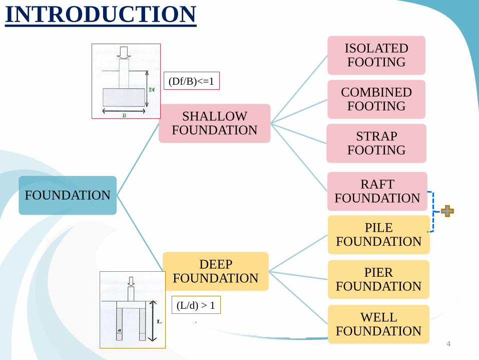
INTRODUCTION
FOUNDATION
SHALLOW FOUNDATION
ISOLATED FOOTING
COMBINED FOOTING
STRAP FOOTING
RAFT FOUNDATION
DEEP FOUNDATION
PILE FOUNDATION
PIER FOUNDATION
WELL FOUNDATION
4
(Df/B)<=1
(L/d) > 1
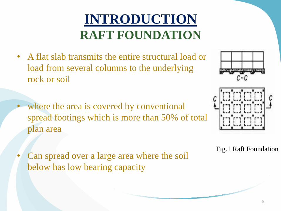
INTRODUCTION
RAFT FOUNDATION
• A flat slab transmits the entire structural load or
load from several columns to the underlying
rock or soil
• where the area is covered by conventional
spread footings which is more than 50% of total
plan area
• Can spread over a large area where the soil
below has low bearing capacity
Fig.1 Raft Foundation
5
INTRODUCTION
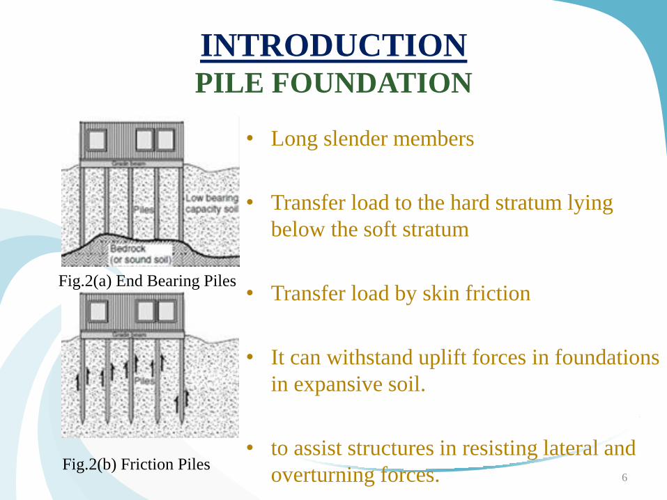
PILE FOUNDATION
• Long slender members
• Transfer load to the hard stratum lying
below the soft stratum
• Transfer load by skin friction
• It can withstand uplift forces in foundations
in expansive soil.
• to assist structures in resisting lateral and
overturning forces.
Fig.2(a) End Bearing Piles
Fig.2(b) Friction Piles 6
PILED RAFT FOUNDATION
NEED FOR PILED RAFT FOUNDATION
• The major disadvantage of Rafts are they will undergo
excessive settlement in case of weak soil & with higher
loads
• In case of free standing pile foundation, they are prone to
differential settlement since the loads from the
superstructure are not equally distributed on all the piles
Piled Raft foundation system which is a combination of
both Rafts and piles are used to overcome the above
disadvantages.
7
PILED RAFT FOUNDATION
8
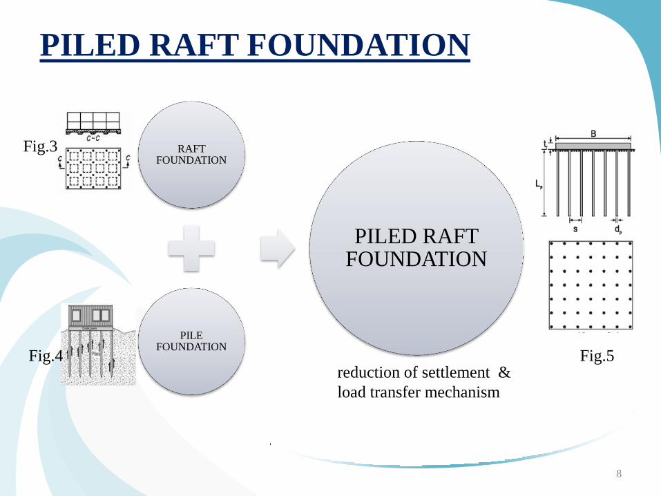
RAFT FOUNDATION
PILE FOUNDATION
PILED RAFT FOUNDATION
reduction of settlement &
load transfer mechanism
Fig.3
Fig.4 Fig.5
WORKING MECHANISM OF PILED RAFT
FOUNDATION
• reduction of settlement & load transfer mechanism
• A geotechnical assessment for design of such a
foundation system therefore needs to consider not only
the capacity of the pile elements and the raft elements, but
their combined capacity and interaction under
serviceability loading.
9
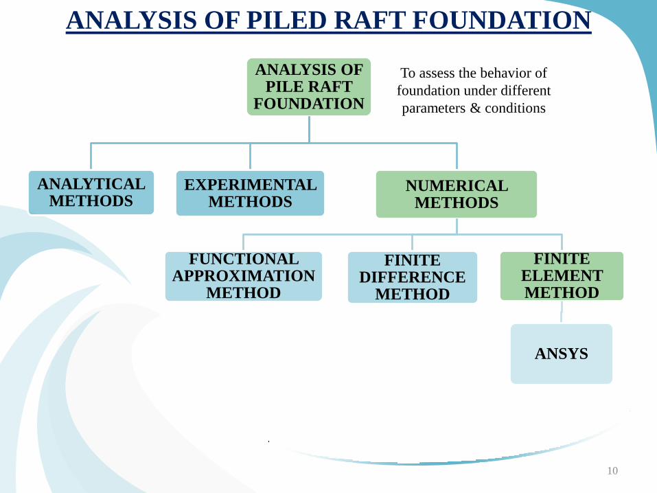
ANALYSIS OF PILED RAFT FOUNDATION
ANALYSIS OF PILE RAFT
FOUNDATION
ANALYTICAL METHODS
EXPERIMENTAL METHODS
NUMERICAL METHODS
FUNCTIONAL APPROXIMATION
METHOD
FINITE DIFFERENCE
METHOD
FINITE ELEMENT METHOD
ANSYS
10
To assess the behavior of
foundation under different
parameters & conditions
FINITE ELEMENT METHOD OF ANALYSIS
• BASIS : representation of a body or a structure by an assemblage of
subdivisions called finite elements.
• all the complexities like material properties, boundary conditions, varying
loads can be taken care of.
• Approximate but acceptable solutions are obtained
Use of computer is the basic and essential part of the finite element analysis
with variety of computer software packages have been used of which one we
are using is ANSYS.
With the advent of computer, this technique can be used for getting better
engineering analysis results.
11
• A sophisticated and leading FEM integrated software package
consisting of whole module required for modeling, meshing, analysis
and post processing of results.
• tailor made for analysis of foundation as it is more versatile and
flexible as the field conditions can be incorporated easily
• capable of analyzing unusual and complex raft shapes, rafts with
different thicknesses, piles with different shapes, piles with different
lengths and diameters of pile, interaction between piles, raft and soil.
ANSYS
12
STEPS IN ANSYS
• Pre Processing mode
Defining element type (for Pile, raft and soil) and element behavior
(Eg: Plane strain)
Assigning material properties
Modeling by joining key points through lines and create areas for
entire dimension of the model.
Meshing the entire model by assigning material properties
Also, model contact elements at the interfaces
Apply Boundary conditions to incorporate field conditions
• Solution and Post Processing mode
A Non-linear analysis is carried out
Results are observed ( Ultimate load carrying capacity and
settlements are observed) from the analysis
13
LITERATURE STUDY [3] Oh. et.al.(2008) FINITE ELEMENT MODELING OF PILED RAFT IN SAND
using PLAXIS.
Raft thickness doesn’t affect the load carrying capacity of foundation
[17] Ningobham Thoiba Singh & Baleshwar Singh studied INTERACTION ANALYSIS FOR PILED RAFTS IN COHESIVE SOILS (2008) using Ansys
Increase in raft thickness hasn’t improved the foundation behavior
greater raft thickness is not generally advantageous in reducing overall or maximum settlement, provide optimum raft thickness
Addition of piles increases the load carrying capacity of a raft with reduction in settlement.
Axial load is maximum at top portion of pile and is minimum at the tip.
[5] Srilakshmi & Chetan Gowda suggested that raft thickness does not have
influence on unifrom settlement & ultimate load capacity of foundatiom 14
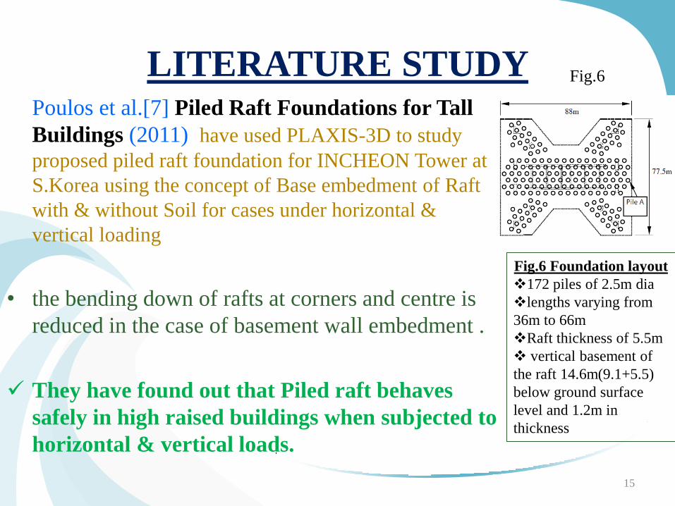
LITERATURE STUDY Poulos et al.[7] Piled Raft Foundations for Tall
Buildings (2011) have used PLAXIS-3D to study
proposed piled raft foundation for INCHEON Tower at
S.Korea using the concept of Base embedment of Raft
with & without Soil for cases under horizontal &
vertical loading
• the bending down of rafts at corners and centre is
reduced in the case of basement wall embedment .
They have found out that Piled raft behaves
safely in high raised buildings when subjected to
horizontal & vertical loads.
15
Fig.6 Foundation layout
172 piles of 2.5m dia
lengths varying from
36m to 66m
Raft thickness of 5.5m
vertical basement of
the raft 14.6m(9.1+5.5)
below ground surface
level and 1.2m in
thickness
Fig.6
LITERATURE STUDY FINDINGS
• It is found out that piled raft foundation is the most effective
system for high rise structures
• Most of the studies were comprised of 2D analysis on piled
raft foundation .
• Most of the analysis were done using softwares other than
ANSYS.
• Influence of raft thickness & pile spacing is stressed often.
17
• Piled raft has major role to play in case of high rise structures
• Analyses carried out on piled rafts mainly dealt with raft
thickness and dimensions of pile
• The work was concentrated on uniform diameter & uniform
length of piles
In this study, the influence of different diameters and different
lengths of pile on the performance of foundation system is
considered.
18
MOTIVATION FOR THE PROJECT
OBJECTIVES OF THE PROJECT
• To study the variables which influence the load carrying
capacity of piled raft foundation & finally to know the
performance of the piled raft foundation system on uniform
sand & clay under vertical load- Parametric study using
FEM Analysis.
• To study the effect of parameters like
Pile diameters in different combinations
Pile length in different combinations
Raft thickness
19
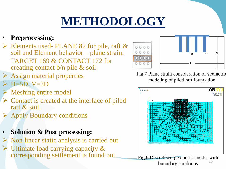
METHODOLOGY
• Preprocessing:
Elements used- PLANE 82 for pile, raft & soil and Element behavior – plane strain.
TARGET 169 & CONTACT 172 for creating contact b/n pile & soil.
Assign material properties
H=5D, V=3D
Meshing entire model
Contact is created at the interface of piled raft & soil.
Apply Boundary conditions
• Solution & Post processing:
Non linear static analysis is carried out
Ultimate load carrying capacity & corresponding settlement is found out.
20
Fig.7 Plane strain consideration of geometric
modeling of piled raft foundation
Fig.8 Discretized geometric model with
boundary condtions
SCOPE OF THE WORK
Influence of different parameters on Ultimate load carrying
capacity of piles will be clearly observed.
The combination of suitable length, diameter of pile, thickness
of raft and type of soil from this study can be optimized for
getting good results in terms of Ultimate load carrying
capacity
21
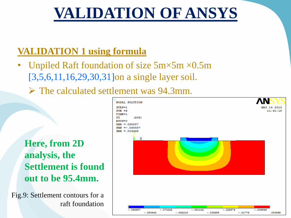
VALIDATION OF ANSYS
VALIDATION 1 using formula
• Unpiled Raft foundation of size 5m×5m ×0.5m
[3,5,6,11,16,29,30,31]on a single layer soil.
The calculated settlement was 94.3mm.
22
Fig.9: Settlement contours for a
raft foundation
Here, from 2D
analysis, the
Settlement is found
out to be 95.4mm.
VALIDATION OF ANSYS
23
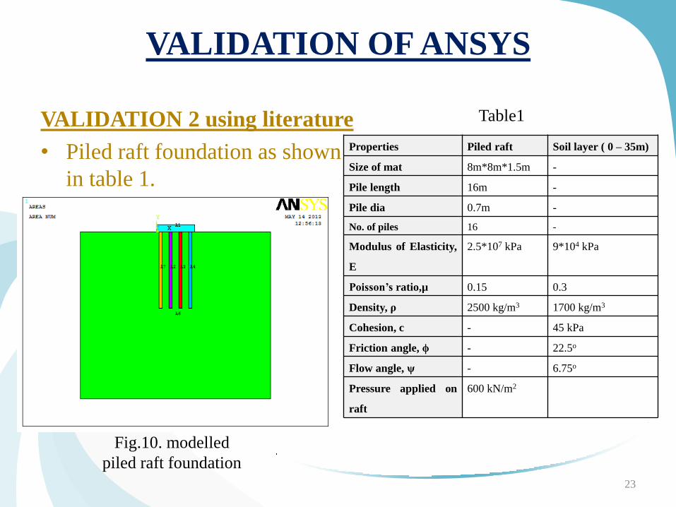
VALIDATION 2 using literature
• Piled raft foundation as shown
in table 1.
Fig.10. modelled
piled raft foundation
Properties Piled raft Soil layer ( 0 – 35m)
Size of mat 8m*8m*1.5m -
Pile length 16m -
Pile dia 0.7m -
No. of piles 16 -
Modulus of Elasticity,
E
2.5*107 kPa 9*104 kPa
Poisson’s ratio,µ 0.15 0.3
Density, ρ 2500 kg/m3 1700 kg/m3
Cohesion, c - 45 kPa
Friction angle, ϕ - 22.5o
Flow angle, ψ - 6.75o
Pressure applied on
raft
600 kN/m2
Table1
24
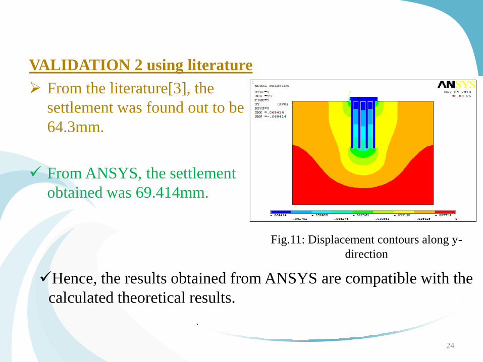
Fig.11: Displacement contours along y-
direction
VALIDATION 2 using literature
From the literature[3], the
settlement was found out to be
64.3mm.
From ANSYS, the settlement
obtained was 69.414mm.
Hence, the results obtained from ANSYS are compatible with the
calculated theoretical results.
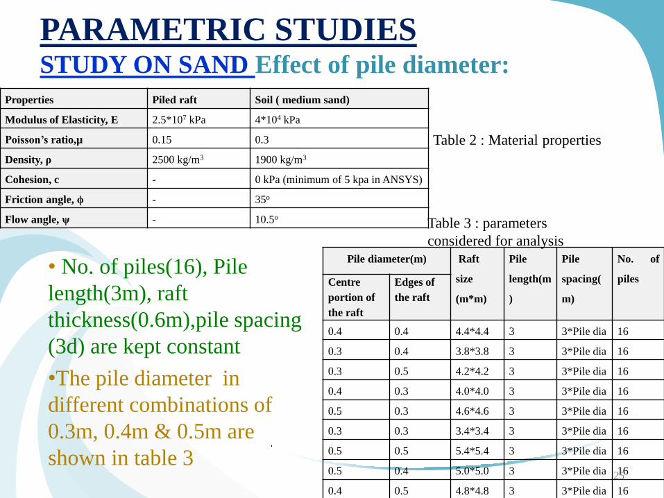
PARAMETRIC STUDIES STUDY ON SAND Effect of pile diameter:
• No. of piles(16), Pile
length(3m), raft
thickness(0.6m),pile spacing
(3d) are kept constant
•The pile diameter in
different combinations of
0.3m, 0.4m & 0.5m are
shown in table 3
25
Table 2 : Material properties
Properties Piled raft Soil ( medium sand)
Modulus of Elasticity, E 2.5*107 kPa 4*104 kPa
Poisson’s ratio,µ 0.15 0.3
Density, ρ 2500 kg/m3 1900 kg/m3
Cohesion, c - 0 kPa (minimum of 5 kpa in ANSYS)
Friction angle, ϕ - 35o
Flow angle, ψ - 10.5o
Pile diameter(m) Raft
size
(m*m)
Pile
length(m
)
Pile
spacing(
m)
No. of
piles Centre
portion of
the raft
Edges of
the raft
0.4 0.4 4.4*4.4 3 3*Pile dia 16
0.3 0.4 3.8*3.8 3 3*Pile dia 16
0.3 0.5 4.2*4.2 3 3*Pile dia 16
0.4 0.3 4.0*4.0 3 3*Pile dia 16
0.5 0.3 4.6*4.6 3 3*Pile dia 16
0.3 0.3 3.4*3.4 3 3*Pile dia 16
0.5 0.5 5.4*5.4 3 3*Pile dia 16
0.5 0.4 5.0*5.0 3 3*Pile dia 16
0.4 0.5 4.8*4.8 3 3*Pile dia 16
Table 3 : parameters
considered for analysis
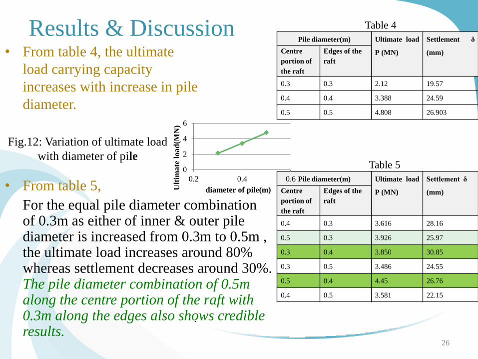
Results & Discussion • From table 4, the ultimate
load carrying capacity
increases with increase in pile
diameter.
26
Pile diameter(m) Ultimate load
P (MN)
Settlement δ
(mm) Centre
portion of
the raft
Edges of the
raft
0.3 0.3 2.12 19.57
0.4 0.4 3.388 24.59
0.5 0.5 4.808 26.903
Table 4
Pile diameter(m) Ultimate load
P (MN)
Settlement δ
(mm) Centre
portion of
the raft
Edges of the
raft
0.4 0.3 3.616 28.16
0.5 0.3 3.926 25.97
0.3 0.4 3.850 30.85
0.3 0.5 3.486 24.55
0.5 0.4 4.45 26.76
0.4 0.5 3.581 22.15
Table 5
• From table 5,
For the equal pile diameter combination of 0.3m as either of inner & outer pile diameter is increased from 0.3m to 0.5m , the ultimate load increases around 80% whereas settlement decreases around 30%. The pile diameter combination of 0.5m along the centre portion of the raft with 0.3m along the edges also shows credible results.
0
2
4
6
0.2 0.4 0.6U
ltim
ate
load
(MN
)
diameter of pile(m)
Fig.12: Variation of ultimate load
with diameter of pile
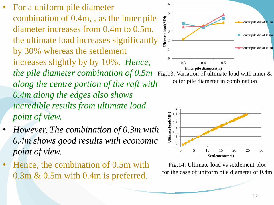
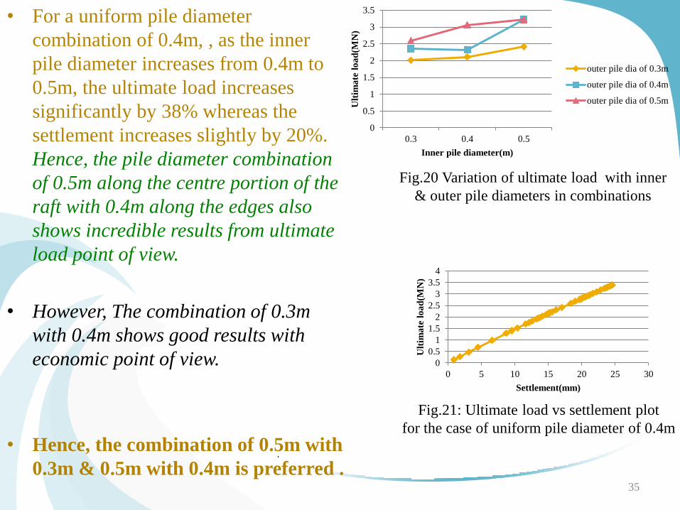
• For a uniform pile diameter
combination of 0.4m, , as the inner pile
diameter increases from 0.4m to 0.5m,
the ultimate load increases significantly
by 30% whereas the settlement
increases slightly by by 10%. Hence,
the pile diameter combination of 0.5m
along the centre portion of the raft with
0.4m along the edges also shows
incredible results from ultimate load
point of view.
• However, The combination of 0.3m with
0.4m shows good results with economic
point of view.
• Hence, the combination of 0.5m with
0.3m & 0.5m with 0.4m is preferred.
27
0
1
2
3
4
5
6
0.3 0.4 0.5
Ult
ima
te l
oa
d(M
N)
Inner pile diameter(m)
outer pile dia of 0.3m
outer pile dia of 0.4m
outer pile dia of 0.5m
Fig.13: Variation of ultimate load with inner &
outer pile diameter in combination
0
0.5
1
1.5
2
2.5
3
3.5
4
0 5 10 15 20 25 30
Ult
ima
te l
oa
d(M
N)
Settlement(mm)
Fig.14: Ultimate load vs settlement plot
for the case of uniform pile diameter of 0.4m
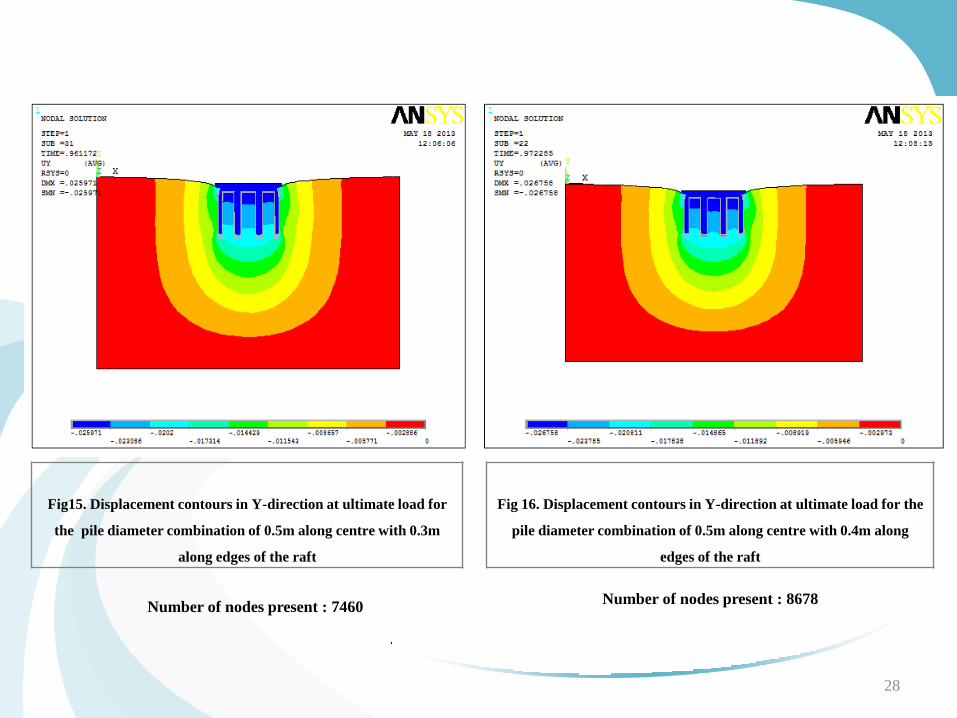
Fig15. Displacement contours in Y-direction at ultimate load for
the pile diameter combination of 0.5m along centre with 0.3m
along edges of the raft
28
Fig 16. Displacement contours in Y-direction at ultimate load for the
pile diameter combination of 0.5m along centre with 0.4m along
edges of the raft
Number of nodes present : 7460 Number of nodes present : 8678
Even though relatively it is difficult for casting different diameters, but it is giving relatively higher values of ultimate load which is cost effective also.
Since, the load carried in case of piled raft foundation is more at the centre of the raft, there is a need to provide larger pile diameter in the central portion of the piled raft.
Greater the pile diameter at the centre of raft, greater is the ultimate load carrying capacity of the foundation system.
Hence, t is ideal to provide a combination of different diameter piles rather than equal diameter piles throughout where different pile diameters lead for better function of foundation.
29
Findings
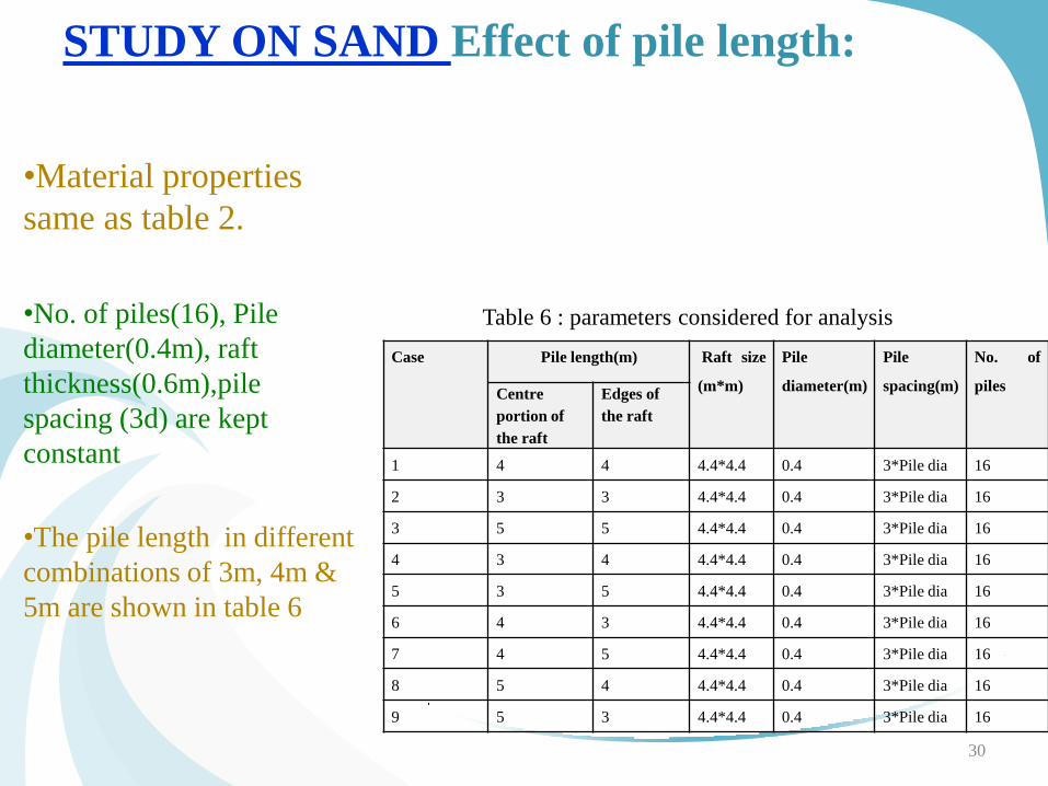
STUDY ON SAND Effect of pile length:
•Material properties
same as table 2.
•No. of piles(16), Pile
diameter(0.4m), raft
thickness(0.6m),pile
spacing (3d) are kept
constant
•The pile length in different
combinations of 3m, 4m &
5m are shown in table 6
30
Case Pile length(m) Raft size
(m*m)
Pile
diameter(m)
Pile
spacing(m)
No. of
piles Centre
portion of
the raft
Edges of
the raft
1 4 4 4.4*4.4 0.4 3*Pile dia 16
2 3 3 4.4*4.4 0.4 3*Pile dia 16
3 5 5 4.4*4.4 0.4 3*Pile dia 16
4 3 4 4.4*4.4 0.4 3*Pile dia 16
5 3 5 4.4*4.4 0.4 3*Pile dia 16
6 4 3 4.4*4.4 0.4 3*Pile dia 16
7 4 5 4.4*4.4 0.4 3*Pile dia 16
8 5 4 4.4*4.4 0.4 3*Pile dia 16
9 5 3 4.4*4.4 0.4 3*Pile dia 16
Table 6 : parameters considered for analysis
Results & Discussion
Pile length(m) Ultimate load P
(MN)
Settlement δ
(mm) Centre
portion of
the raft
Edges of the raft
3 3 3.388 24.59
4 4 3.037 20.99
5 5 2.251 15.12
31
Table 7
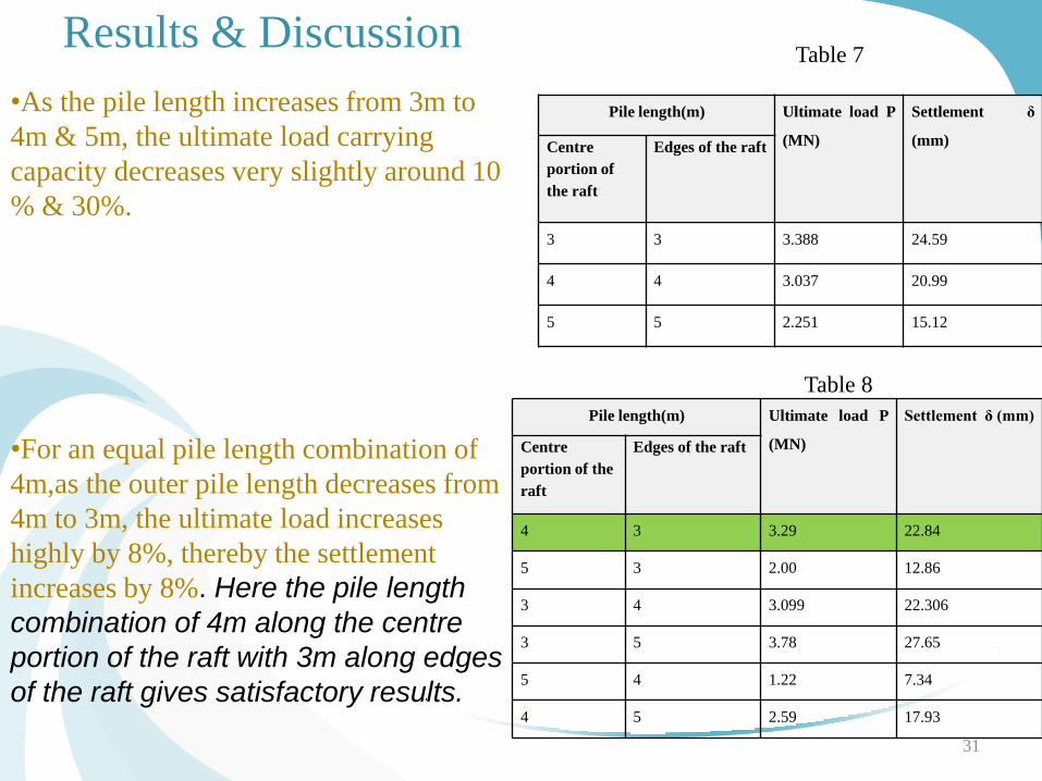
•As the pile length increases from 3m to
4m & 5m, the ultimate load carrying
capacity decreases very slightly around 10
% & 30%.
•For an equal pile length combination of
4m,as the outer pile length decreases from
4m to 3m, the ultimate load increases
highly by 8%, thereby the settlement
increases by 8%. Here the pile length
combination of 4m along the centre
portion of the raft with 3m along edges
of the raft gives satisfactory results.
Pile length(m) Ultimate load P
(MN)
Settlement δ (mm)
Centre
portion of the
raft
Edges of the raft
4 3 3.29 22.84
5 3 2.00 12.86
3 4 3.099 22.306
3 5 3.78 27.65
5 4 1.22 7.34
4 5 2.59 17.93
Table 8
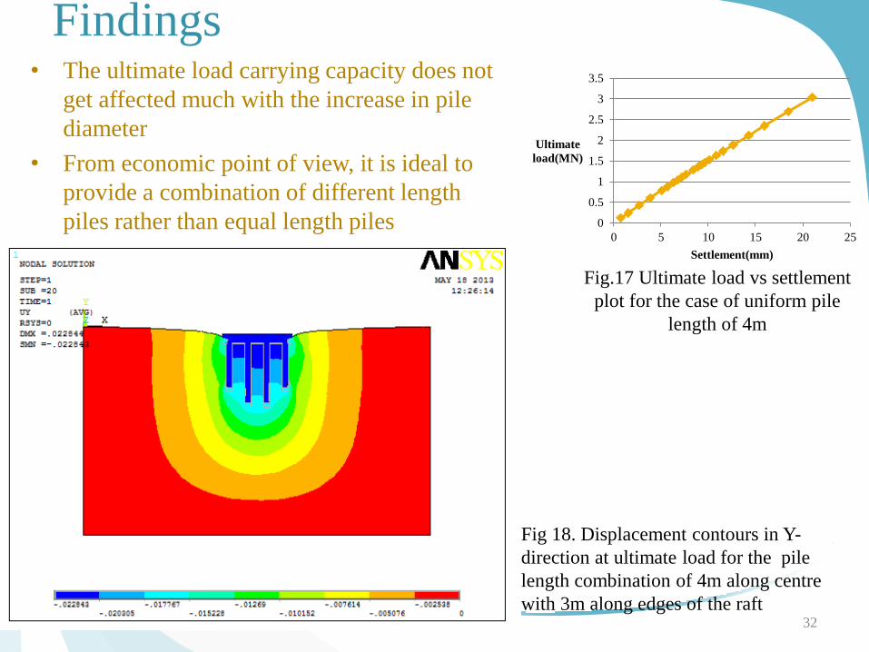
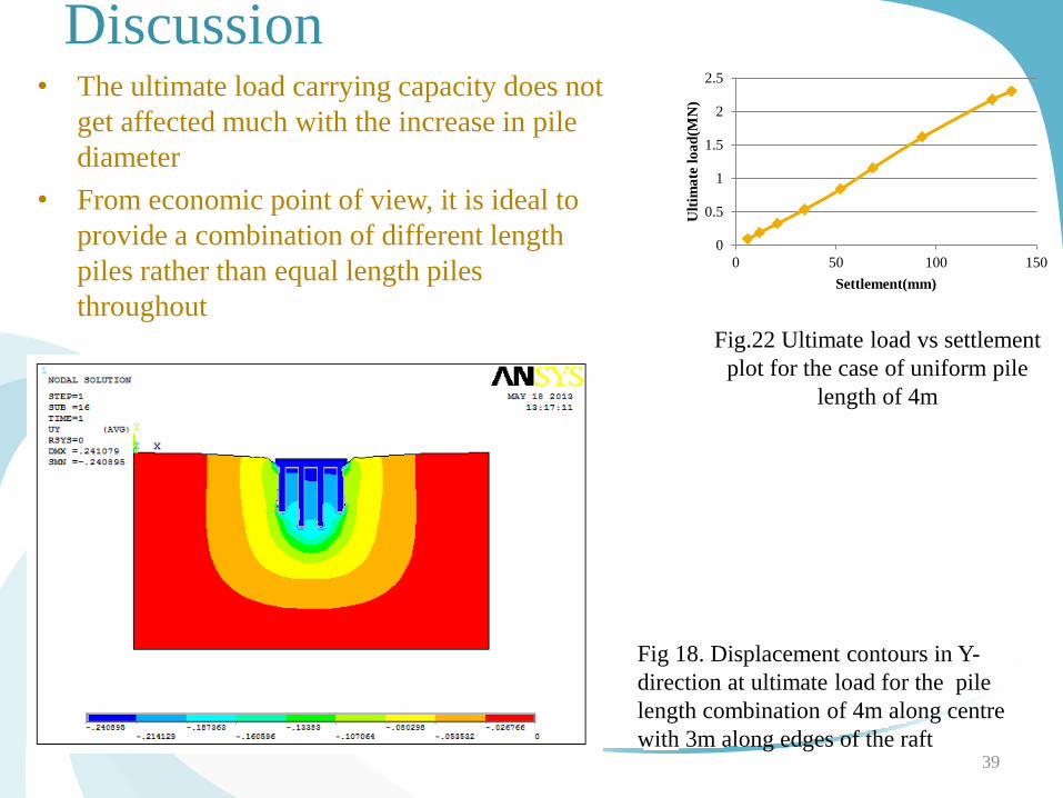
Findings • The ultimate load carrying capacity does not
get affected much with the increase in pile
diameter
• From economic point of view, it is ideal to
provide a combination of different length
piles rather than equal length piles
throughout
32
0
0.5
1
1.5
2
2.5
3
3.5
0 5 10 15 20 25
Ultimate
load(MN)
Settlement(mm)
Fig.17 Ultimate load vs settlement
plot for the case of uniform pile
length of 4m
Fig 18. Displacement contours in Y-
direction at ultimate load for the pile
length combination of 4m along centre
with 3m along edges of the raft
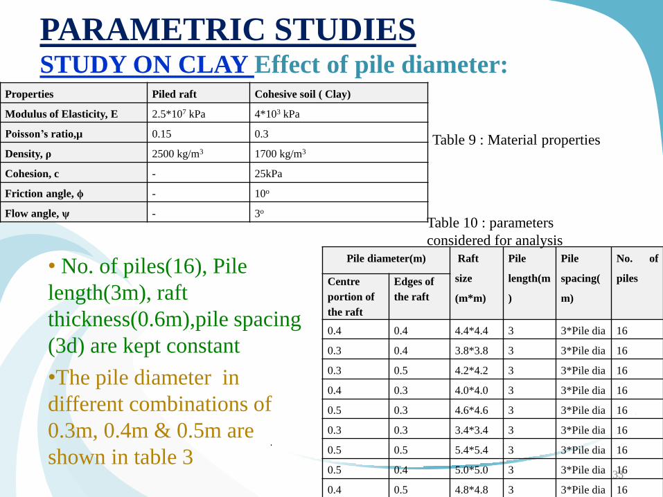
PARAMETRIC STUDIES STUDY ON CLAY Effect of pile diameter:
• No. of piles(16), Pile
length(3m), raft
thickness(0.6m),pile spacing
(3d) are kept constant
•The pile diameter in
different combinations of
0.3m, 0.4m & 0.5m are
shown in table 3
33
Table 9 : Material properties
Pile diameter(m) Raft
size
(m*m)
Pile
length(m
)
Pile
spacing(
m)
No. of
piles Centre
portion of
the raft
Edges of
the raft
0.4 0.4 4.4*4.4 3 3*Pile dia 16
0.3 0.4 3.8*3.8 3 3*Pile dia 16
0.3 0.5 4.2*4.2 3 3*Pile dia 16
0.4 0.3 4.0*4.0 3 3*Pile dia 16
0.5 0.3 4.6*4.6 3 3*Pile dia 16
0.3 0.3 3.4*3.4 3 3*Pile dia 16
0.5 0.5 5.4*5.4 3 3*Pile dia 16
0.5 0.4 5.0*5.0 3 3*Pile dia 16
0.4 0.5 4.8*4.8 3 3*Pile dia 16
Table 10 : parameters
considered for analysis
Properties Piled raft Cohesive soil ( Clay)
Modulus of Elasticity, E 2.5*107 kPa 4*103 kPa
Poisson’s ratio,µ 0.15 0.3
Density, ρ 2500 kg/m3 1700 kg/m3
Cohesion, c - 25kPa
Friction angle, ϕ - 10o
Flow angle, ψ - 3o
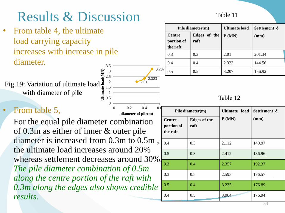
Results & Discussion • From table 4, the ultimate
load carrying capacity
increases with increase in pile
diameter.
34
Table 11
Table 12
• From table 5,
For the equal pile diameter combination of 0.3m as either of inner & outer pile diameter is increased from 0.3m to 0.5m , the ultimate load increases around 20% whereas settlement decreases around 30%. The pile diameter combination of 0.5m along the centre portion of the raft with 0.3m along the edges also shows credible results.
Fig.19: Variation of ultimate load
with diameter of pile
Pile diameter(m) Ultimate load
P (MN)
Settlement δ
(mm) Centre
portion of
the raft
Edges of the
raft
0.3 0.3 2.01 201.34
0.4 0.4 2.323 144.56
0.5 0.5 3.207 156.92
2.01 2.323
3.207
0
0.5
1
1.5
2
2.5
3
3.5
0 0.2 0.4 0.6
Ult
ima
te l
oa
d(M
N)
diameter of pile(m) Pile diameter(m) Ultimate load
P (MN)
Settlement δ
(mm) Centre
portion of
the raft
Edges of the
raft
0.4 0.3 2.112 140.97
0.5 0.3 2.412 136.96
0.3 0.4 2.357 192.37
0.3 0.5 2.593 176.57
0.5 0.4 3.225 176.89
0.4 0.5 3.064 176.94
• For a uniform pile diameter
combination of 0.4m, , as the inner
pile diameter increases from 0.4m to
0.5m, the ultimate load increases
significantly by 38% whereas the
settlement increases slightly by 20%.
Hence, the pile diameter combination
of 0.5m along the centre portion of the
raft with 0.4m along the edges also
shows incredible results from ultimate
load point of view.
• However, The combination of 0.3m
with 0.4m shows good results with
economic point of view.
• Hence, the combination of 0.5m with
0.3m & 0.5m with 0.4m is preferred . 35
0
0.5
1
1.5
2
2.5
3
3.5
4
0 5 10 15 20 25 30
Ult
ima
te l
oa
d(M
N)
Settlement(mm)
Fig.21: Ultimate load vs settlement plot
for the case of uniform pile diameter of 0.4m
0
0.5
1
1.5
2
2.5
3
3.5
0.3 0.4 0.5
Ult
ima
te l
oa
d(M
N)
Inner pile diameter(m)
outer pile dia of 0.3m
outer pile dia of 0.4m
outer pile dia of 0.5m
Fig.20 Variation of ultimate load with inner
& outer pile diameters in combinations
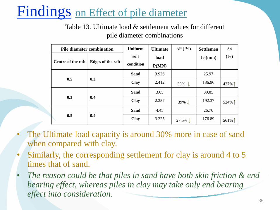
Findings on Effect of pile diameter
36
Table 13. Ultimate load & settlement values for different
pile diameter combinations
• The Ultimate load capacity is around 30% more in case of sand when compared with clay.
• Similarly, the corresponding settlement for clay is around 4 to 5 times that of sand.
• The reason could be that piles in sand have both skin friction & end bearing effect, whereas piles in clay may take only end bearing effect into consideration.
Pile diameter combination Uniform
soil
condition
Ultimate
load
P(MN)
∆P ( %) Settlemen
t δ(mm)
∆δ
(%)
Centre of the raft Edges of the raft
0.5 0.3
Sand 3.926 25.97
Clay 2.412 39% ↓ 136.96 427%↑
0.3 0.4
Sand 3.85 30.85
Clay 2.357 39% ↓ 192.37 524%↑
0.5 0.4
Sand 4.45 26.76
Clay 3.225 27.5% ↓ 176.89 561%↑
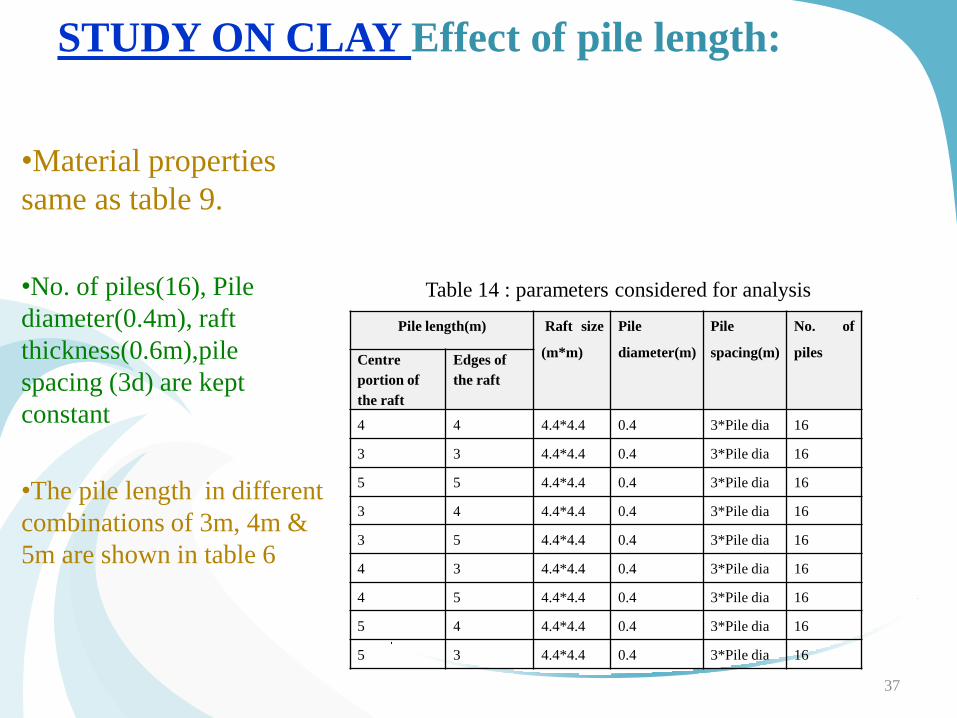
STUDY ON CLAY Effect of pile length:
•Material properties
same as table 9.
•No. of piles(16), Pile
diameter(0.4m), raft
thickness(0.6m),pile
spacing (3d) are kept
constant
•The pile length in different
combinations of 3m, 4m &
5m are shown in table 6
37
Pile length(m) Raft size
(m*m)
Pile
diameter(m)
Pile
spacing(m)
No. of
piles Centre
portion of
the raft
Edges of
the raft
4 4 4.4*4.4 0.4 3*Pile dia 16
3 3 4.4*4.4 0.4 3*Pile dia 16
5 5 4.4*4.4 0.4 3*Pile dia 16
3 4 4.4*4.4 0.4 3*Pile dia 16
3 5 4.4*4.4 0.4 3*Pile dia 16
4 3 4.4*4.4 0.4 3*Pile dia 16
4 5 4.4*4.4 0.4 3*Pile dia 16
5 4 4.4*4.4 0.4 3*Pile dia 16
5 3 4.4*4.4 0.4 3*Pile dia 16
Table 14 : parameters considered for analysis
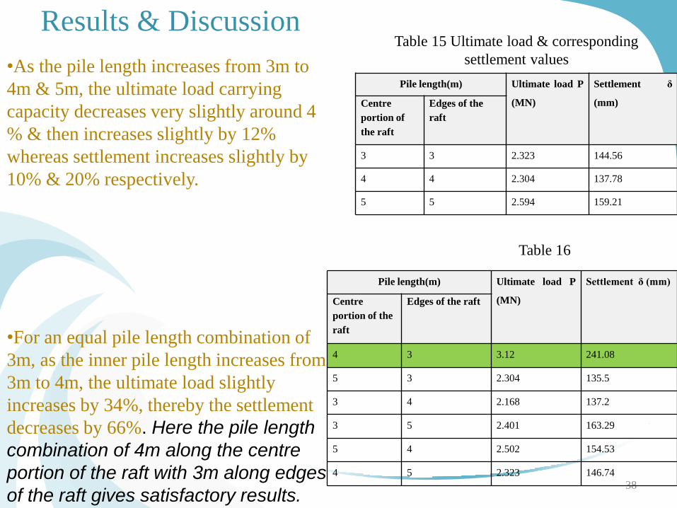
Results & Discussion
38
Table 15 Ultimate load & corresponding
settlement values •As the pile length increases from 3m to
4m & 5m, the ultimate load carrying
capacity decreases very slightly around 4
% & then increases slightly by 12%
whereas settlement increases slightly by
10% & 20% respectively.
•For an equal pile length combination of
3m, as the inner pile length increases from
3m to 4m, the ultimate load slightly
increases by 34%, thereby the settlement
decreases by 66%. Here the pile length
combination of 4m along the centre
portion of the raft with 3m along edges
of the raft gives satisfactory results.
Table 16
Pile length(m) Ultimate load P
(MN)
Settlement δ
(mm) Centre
portion of
the raft
Edges of the
raft
3 3 2.323 144.56
4 4 2.304 137.78
5 5 2.594 159.21
Pile length(m) Ultimate load P
(MN)
Settlement δ (mm)
Centre
portion of the
raft
Edges of the raft
4 3 3.12 241.08
5 3 2.304 135.5
3 4 2.168 137.2
3 5 2.401 163.29
5 4 2.502 154.53
4 5 2.323 146.74
Discussion • The ultimate load carrying capacity does not
get affected much with the increase in pile
diameter
• From economic point of view, it is ideal to
provide a combination of different length
piles rather than equal length piles
throughout
39
Fig.22 Ultimate load vs settlement
plot for the case of uniform pile
length of 4m
Fig 18. Displacement contours in Y-
direction at ultimate load for the pile
length combination of 4m along centre
with 3m along edges of the raft
0
0.5
1
1.5
2
2.5
0 50 100 150
Ult
ima
te l
oa
d(M
N)
Settlement(mm)
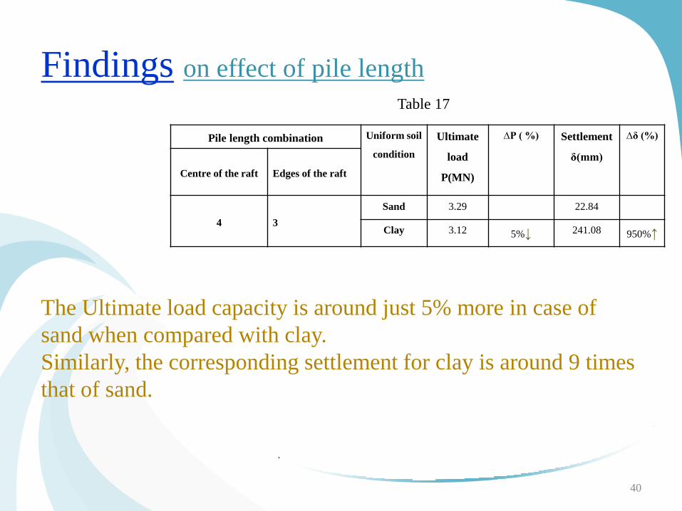
Findings on effect of pile length
Pile length combination Uniform soil
condition
Ultimate
load
P(MN)
∆P ( %) Settlement
δ(mm)
∆δ (%)
Centre of the raft Edges of the raft
4 3
Sand 3.29 22.84
Clay 3.12 5%↓ 241.08 950%↑
40
Table 17
The Ultimate load capacity is around just 5% more in case of
sand when compared with clay.
Similarly, the corresponding settlement for clay is around 9 times
that of sand.
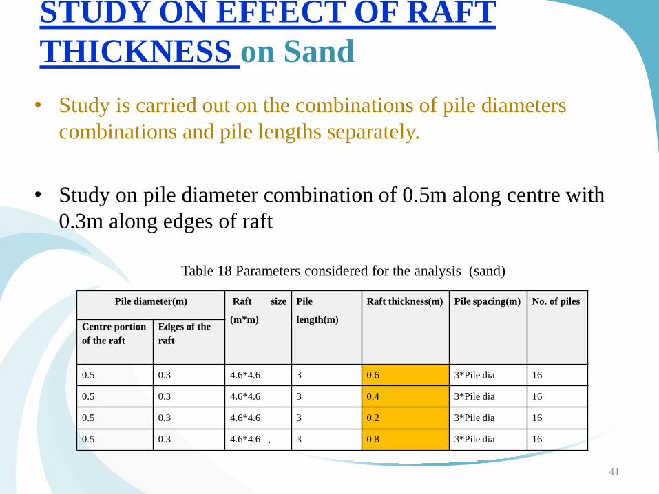
STUDY ON EFFECT OF RAFT
THICKNESS on Sand
• Study is carried out on the combinations of pile diameters
combinations and pile lengths separately.
• Study on pile diameter combination of 0.5m along centre with
0.3m along edges of raft
41
Table 18 Parameters considered for the analysis (sand)
Pile diameter(m) Raft size
(m*m)
Pile
length(m)
Raft thickness(m) Pile spacing(m) No. of piles
Centre portion
of the raft
Edges of the
raft
0.5 0.3 4.6*4.6 3 0.6 3*Pile dia 16
0.5 0.3 4.6*4.6 3 0.4 3*Pile dia 16
0.5 0.3 4.6*4.6 3 0.2 3*Pile dia 16
0.5 0.3 4.6*4.6 3 0.8 3*Pile dia 16
Pile diameter(m) Raft thickness(m) Ultimate load
P (MN)
∆P (%) Settlement δ
(mm)
∆ δ (%)
Centre
portion of
the raft
Edges of
the raft
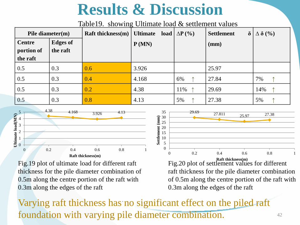
0.5 0.3 0.6 3.926 25.97
0.5 0.3 0.4 4.168 6% ↑ 27.84 7% ↑
0.5 0.3 0.2 4.38 11% ↑ 29.69 14% ↑
0.5 0.3 0.8 4.13 5% ↑ 27.38 5% ↑
42
Results & Discussion Table19. showing Ultimate load & settlement values
4.38 4.168 3.926 4.13
0
1
2
3
4
5
0 0.2 0.4 0.6 0.8 1
Ult
ima
te l
oa
d(M
N)
Raft thickness(m)
29.69 27.811
25.97 27.38
0
5
10
15
20
25
30
35
0 0.2 0.4 0.6 0.8 1
Set
tlem
ent
(mm
) Raft thickness(m)
Fig.19 plot of ultimate load for different raft
thickness for the pile diameter combination of
0.5m along the centre portion of the raft with
0.3m along the edges of the raft
Fig.20 plot of settlement values for different
raft thickness for the pile diameter combination
of 0.5m along the centre portion of the raft with
0.3m along the edges of the raft
Varying raft thickness has no significant effect on the piled raft
foundation with varying pile diameter combination.
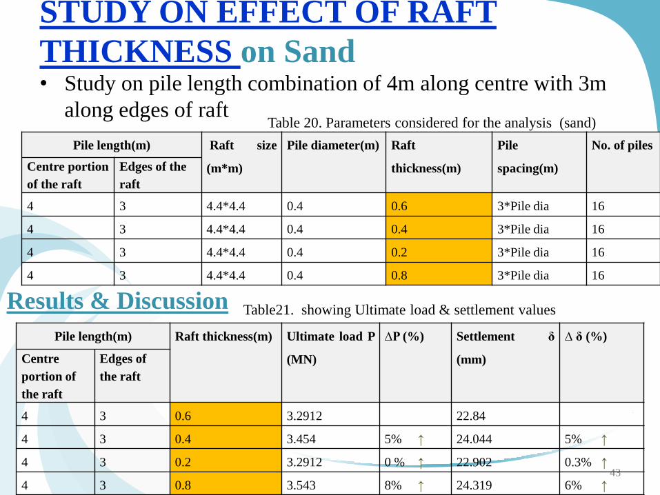
STUDY ON EFFECT OF RAFT
THICKNESS on Sand • Study on pile length combination of 4m along centre with 3m
along edges of raft
43
Table 20. Parameters considered for the analysis (sand)
Pile length(m) Raft size
(m*m)
Pile diameter(m) Raft
thickness(m)
Pile
spacing(m)
No. of piles
Centre portion
of the raft
Edges of the
raft
4 3 4.4*4.4 0.4 0.6 3*Pile dia 16
4 3 4.4*4.4 0.4 0.4 3*Pile dia 16
4 3 4.4*4.4 0.4 0.2 3*Pile dia 16
4 3 4.4*4.4 0.4 0.8 3*Pile dia 16
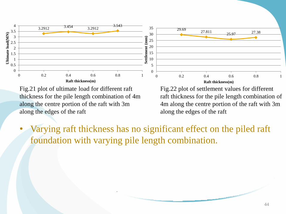
Results & Discussion Table21. showing Ultimate load & settlement values
Pile length(m) Raft thickness(m) Ultimate load P
(MN)
∆P (%) Settlement δ
(mm)
∆ δ (%)
Centre
portion of
the raft
Edges of
the raft
4 3 0.6 3.2912 22.84
4 3 0.4 3.454 5% ↑ 24.044 5% ↑
4 3 0.2 3.2912 0 % ↑ 22.902 0.3% ↑
4 3 0.8 3.543 8% ↑ 24.319 6% ↑
44
Fig.21 plot of ultimate load for different raft
thickness for the pile length combination of 4m
along the centre portion of the raft with 3m
along the edges of the raft
Fig.22 plot of settlement values for different
raft thickness for the pile length combination of
4m along the centre portion of the raft with 3m
along the edges of the raft
• Varying raft thickness has no significant effect on the piled raft
foundation with varying pile length combination.
3.2912 3.454
3.2912 3.543
0
0.5
1
1.5
2
2.5
3
3.5
4
0 0.2 0.4 0.6 0.8 1
Ult
ima
te l
oa
d(M
N)
Raft thickness(m)
29.69 27.811
25.97 27.38
0
5
10
15
20
25
30
35
0 0.2 0.4 0.6 0.8 1
Set
tlem
ent
(mm
)
Raft thickness(m)
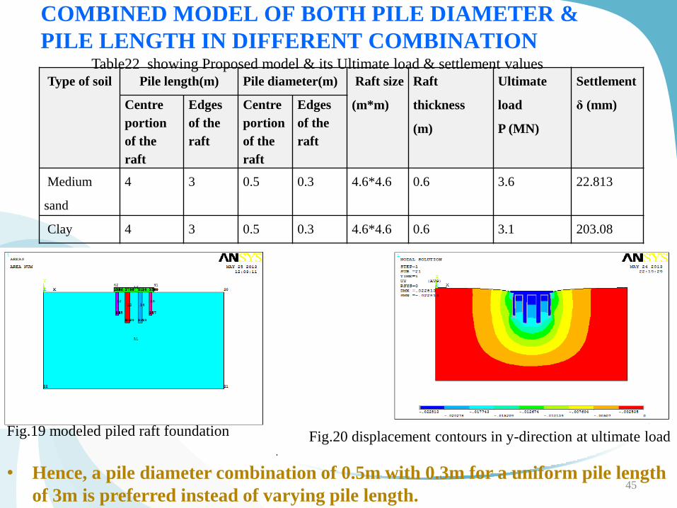
COMBINED MODEL OF BOTH PILE DIAMETER &
PILE LENGTH IN DIFFERENT COMBINATION
Type of soil Pile length(m) Pile diameter(m) Raft size
(m*m)
Raft
thickness
(m)
Ultimate
load
P (MN)
Settlement
δ (mm) Centre
portion
of the
raft
Edges
of the
raft
Centre
portion
of the
raft
Edges
of the
raft
Medium
sand
4 3 0.5 0.3 4.6*4.6 0.6 3.6 22.813
Clay 4 3 0.5 0.3 4.6*4.6 0.6 3.1 203.08
45
Fig.19 modeled piled raft foundation Fig.20 displacement contours in y-direction at ultimate load
Table22 showing Proposed model & its Ultimate load & settlement values
• Hence, a pile diameter combination of 0.5m with 0.3m for a uniform pile length
of 3m is preferred instead of varying pile length.
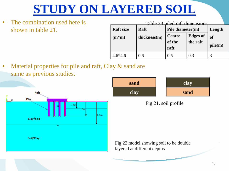
STUDY ON LAYERED SOIL • The combination used here is
shown in table 21.
46
Raft size
(m*m)
Raft
thickness(m)
Pile diameter(m) Length
of
pile(m)
Centre
of the
raft
Edges of
the raft
4.6*4.6 0.6 0.5 0.3 3
Table 23 piled raft dimensions
• Material properties for pile and raft, Clay & sand are
same as previous studies.
sand
clay
clay
sand
Fig 21. soil profile
Fig.22 model showing soil to be double
layered at different depths
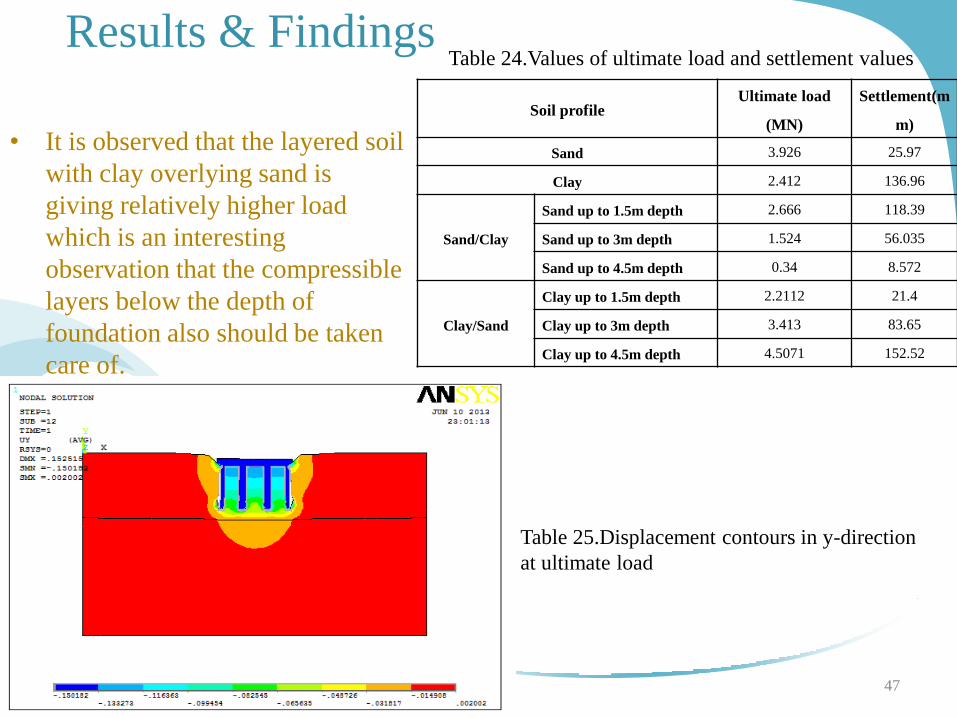
Results & Findings
47
• It is observed that the layered soil
with clay overlying sand is
giving relatively higher load
which is an interesting
observation that the compressible
layers below the depth of
foundation also should be taken
care of.
Table 24.Values of ultimate load and settlement values
Soil profile Ultimate load
(MN)
Settlement(m
m)
Sand 3.926 25.97
Clay 2.412 136.96
Sand/Clay
Sand up to 1.5m depth 2.666 118.39
Sand up to 3m depth 1.524 56.035
Sand up to 4.5m depth 0.34 8.572
Clay/Sand
Clay up to 1.5m depth 2.2112 21.4
Clay up to 3m depth 3.413 83.65
Clay up to 4.5m depth 4.5071 152.52
Table 25.Displacement contours in y-direction
at ultimate load
CONCLUSION
• Pile diameter has significant influence on the ultimate capacity
of piled raft foundation.
• Varying Pile diameters that too in combination has significant
effect on the ultimate capacity of the foundation system. Instead
of equal pile diameters throughout in a piled raft system, a
combination of different inner & outer pile diameters in
combination is suggested.
• In case of foundation in sand, ultimate load carrying capacity of
foundation increases by 126% with increase in pile diameter
from 0.3 to 0.5 m uniformly.
48
CONCLUSION
• In case of foundation in sand, the pile diameter combination of 0.3m along
the centre portion of the raft with 0.4m along the edges of the raft shows
best results with respect to ultimate load capacity point of view.
Similarly, pile diameter combination of 0.5m along the centre portion of the
raft with 0.3m along the edges also shows acceptable results.
From economic point of view, the pile diameter combination of 0.3m along
the centre with 0.4m along the edges of raft is suggested
• Same combinations for foundation in clays showed good results.
• In case of foundation in clayey soil, the ultimate load capacity increases by
60% with increase in pile diameter from 0.3 to 0.5 m uniformly. This
implies that it has a considerable effect on the behavior of the foundation.
• It is concluded that piled raft foundations having higher pile diameter at the
centre and smaller diameter at the edges is preferred for higher ultimate
loads.
49
CONCLUSION • Varying pile lengths throughout uniformly does not have significant
effect on the ultimate load carrying capacity of the foundation.
• Hence, pile length has no significant effect on the behavior of the foundation on both sand & clay.
• However, in case of foundation in both sand & clay, a pile length combination of 4m along the centre with 3m along the edges of raft shows credible results.
• Further parametric studies shows that the raft thickness does not affect much on the ultimate load carrying capacity of the foundation.
• Ultimate capacity of foundation in sand is around 50% more than that of clay.
• The layered soil with clay overlying sand is giving relatively higher loads when compared with that of sand overlying clay.
50
SCOPE FOR FURTHER STUDY
• Foundation system can be analyzed by different soil in multiple
layers for the combination of different pile lengths & pile diameters.
• Research can be carried on 3-D modeling for analysis of piled raft
under load & bending moment.
51
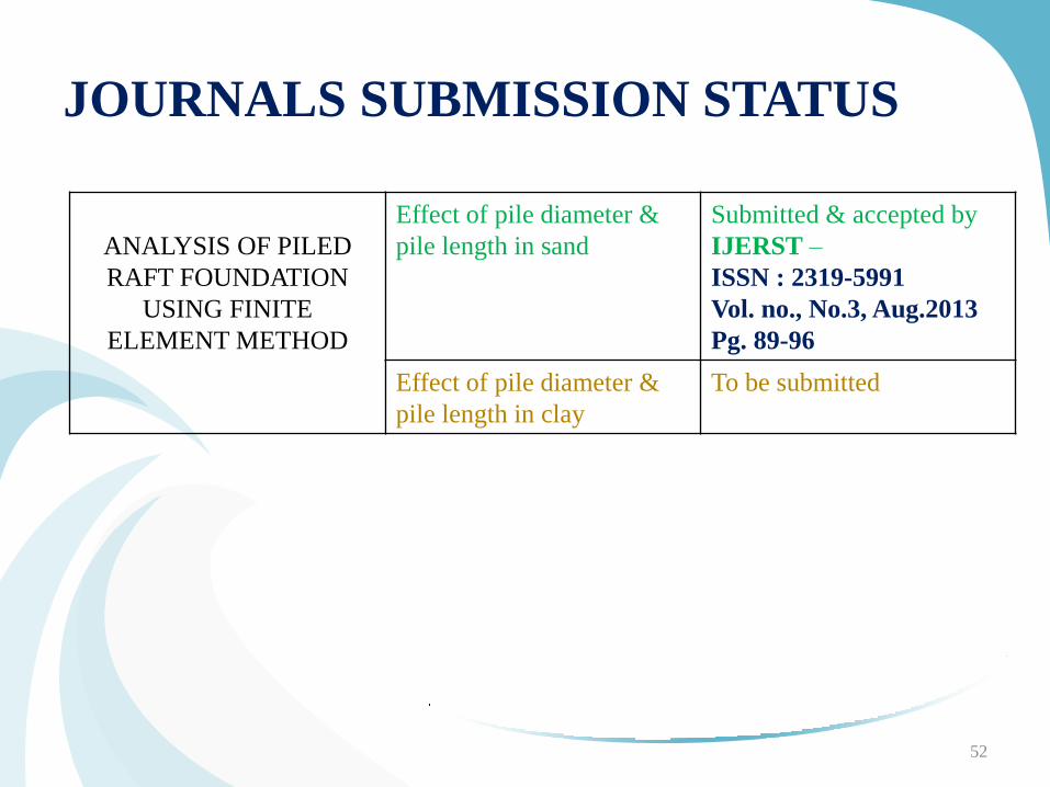
JOURNALS SUBMISSION STATUS
ANALYSIS OF PILED
RAFT FOUNDATION
USING FINITE
ELEMENT METHOD
Effect of pile diameter &
pile length in sand
Submitted & accepted by
IJERST –
ISSN : 2319-5991
Vol. no., No.3, Aug.2013
Pg. 89-96
Effect of pile diameter &
pile length in clay
To be submitted
52
REFERENCES
1. Dang Dinh Chung Nguyen, Seong-Bae Jo and Dong-Soo Kim(2013), “Design Method of
Piled-Raft Foundations under Vertical Load Considering Interaction Effects”, Science direct-
Computers and Geotechnics, Vol. 47, pp. 16–27
2. Der-Guey Lin and Zheng-Yi Feng(2006), “A Numerical Study Of Piled Raft Foundations”,
Journal of the Chinese Institute of Engineers, Vol. 29, , pp. 1091-1097
3. E.Y. N Oh, M. Huang, C. Surarak and A. S. Balasubramaniam (2008) , “Finite Element
Modeling For Piled Raft Foundation in Sand”, Eleventh East Asia-Pacific Conference on
Structural Engineering & Construction (EASEC-11) ; Building a Sustainable Environment;
Taipei; Taiwan, pp. 1-8
4. Emilios M. Comodromos , Mello C. Papadopoulou and Ioannis K. Rentzeperis(2009), “Pile
Foundation Analysis and Design Using Experimental Data And 3-D Numerical Analysis”,
Science direct - Computers and Geotechnics, Vol. 36 , pp. 819–836
5. G.Srilakshmi and Chethan Gowda R.K (2012), “Analysis of Piled raft foundation by Finite
Element method”, Dissertation report to VTU Belgaum.
6. G. Srilakshmi and Rekha (2011), “Analysis of Mat Foundation Using Finite Element
Method”, International Journal of Earth Sciences and Engineering, Vol. 4, pp. 113-115
53
REFERENCES 7. H.G. Poulos, J.C. Small and H. Chow (2011), “Pile Raft Foundation For Tall Buildings”,
Geotechnical Engineering Journal of the SEAGS & AGSSEA, Vol.42, pp. 78-84
8. Helen Sze Wai Chow(2007), “Analysis of piled raft foundations with piles of different and diameters”, Doctoral Thesis submitted to University of Sydney School of Engineering, August 2007.
9. J.C. Small and H.H. Zhang (2002), “Behavior of Piled Raft Foundations under Lateral and Vertical Loading”, The International Journal of Geo mechanics, Vol.2, pp. 29–45
10. Jaeyeon Cho, Jin-HyungLee, SangseomJeong and JaehwanLee (2012), “The Settlement Behavior Of Piled Raft In Clay Soils”, Science Verse – Science direct - Ocean Engineering, Vol.53,pp. 153–163
11. Joseph E Bowles, Foundation Analysis and Design, McGraw- Hill Companies, 5th edition, New York, 1997.
12. JinHyung Lee, Youngho Kim and Sangseom Jeong(2010), “Three-Dimensional Analysis of Bearing Behavior Of Piled Raft On Soft Clay”, Science direct - Computers and Geotechnics, Vol. 37, pp. 103–114
54
REFERENCES
13. Luca de Sanctis and Alessandro Mandolini(2006), “Bearing Capacity Of Pr On Soft Clays”,
Journal of Geotechnical And Geoenvironmental Engineering; vol. 132, pp.1600-1610.
14. Luca de Sanctis and Gianpiero Russo (2008), “Analysis and Performance of Piled Rafts
Designed Using Innovative Criteria”, Journal of Geotechnical And Geoenvironmental
Engineering, vol.134, pp. 1118-1128
15. M. H. Baziar, A. Ghorbani and R. Katzenbach (2009), Three-Dimensional Analysis of Pile-
Raft Foundation On Medium-Dense Sand, International Journal of Civil Engineering, Vol. 7,
pp. 170 -175.
16. Nainan P Kurian and G.Srilakshmi(2003), “Studies on behavior of under reamed piles in
normal and expansive soils by finite element method”, Doctoral Thesis, Indian Institute of
Technology, Madras, Chennai, India
17. Ningombam Thoiba Singh and Baleshwar Singh(2008), “Interaction Analysis For Piled
Rafts In Cohesive Soils”, The 12th International Conference of International Association for
Computer Methods and Advances in Geomechanics (IACMAG); 1-6 October 2008; Goa;
India, pp. 3289-3296
55
REFERENCES 18. Oliver Reul (2004), “Numerical study of the bearing behavior of piled rafts”, International
Journal Of Geomechanical Engineering, Vol.4, pp. 59-68
19. Oliver Reul and Mark F. Randolph (2004), “Design Strategies For Piled Rafts Subjected to
Nonuniform Vertical Loading”, Journal of Geotechnical & Geoenvironmental Engineering,
vol 130, pp. 1-13.
20. Phung Duc Long (2010), “Piled Raft – A Cost-Effective Foundation Method For High-
Rises”, Geotechnical Engineering Journal of the SEAGS & AGSSEA, Vol. 41, pp. 1-12
21. R. P. Cunha, H. G. Poulos and J. C. Small(2001), “Investigation of Design Alternatives for a
Piled Raft Case History”, Journal Of Geotechnical And Geoenvironmental Engineering, vol.
127, pp. 635-641
22. R. Ziaie-Moayed, M.Kamalzare and M. Safavian(2010), “Evaluation Of Piled Raft
Foundations Behavior With Different Dimensions of Piles”, Journal of Applied Sciences
,Vol.10, pp.1320-1325
23. Rajendra Singh Bisht and Baleshwar Singh(2012) , “Study On Behaviour Of Piled Raft
Foundation By Numerical Modelling” , SAITM Research Symposium on Engineering
Advancements (SAITM – RSEA 2012),Indian Institute of Technology, Guwahati.
56
REFERENCES 24. Widjojo A. Prakoso and Fred H. Kulhawy(2001), “Contribution To Piled Raft Foundation Design”,
Journal of Geotechnical & Geoenvironmental Engineering , vol. 127, pp. 17-24
25. Y. F. Leung , A. Klar, and K. Soga(2010), “Theoretical Study On Pile Length Optimization Of Pile
Groups And Piled Rafts”, Journal Of Geotechnical And Geoenvironmental Engineering, vol. 136, pp.
319-330
26. Zehai Cheng Zhejiang (2011) , “Prediction And Measurement Of Settlement Of A Piled Raft
Foundation Over Thick Soft Ground”, EJGE ,Vol. 16 ; Bund. A, pp. 125-136
27. CODE OF PRACTICE FOR DESIGN AND CONSTRUCTION OF PILE FOUNDATIONS.
IS:2911(PART I/SECI)-1979
28. CODE OF PRACTICE FOR CALCULATION OF SETTLEMENTS OF FOUNDATIONS.
IS:8009(PART I)-1976
29. CODE OF PRACTICE FOR DETERMINATION OF BREAKING CAPACITYOF SHALLOW
FOUNDATIONS. IS 6403:1981
30. CODE OF PRACTICE FOR DESIGN AND CONSTRUCTION OF RAFT FOUNDATIONS.
IS:2950(PART I)-1981
31. V.N.S Murthy, Soil mechanics and Foundation Engineering, CBS Publishers and Distributors
Bangalore, 2007
57