mtl zirconia oxygen analyser mtl zirconia oxygen analyser february 2017 inm mtl 130-0200 rev 4...
TRANSCRIPT
Z130 MTL zirconia oxygen analyser
February 2017INM MTL 130-0200 Rev 4
Instruction manualMTL gas analysers & systems

ii INM MTL 130-0200 Rev 4
DECLARATION OF CONFORMITY
A printed version of the Declaration of Conformity has been provided separately within the original shipment of goods. However, you can find a copy of the latest version at -
http://www.mtl-inst.com/certificates
INM MTL 130-0200 Rev 4 iii
CONTENTS
DECLARATION OF CONFORMITY . . . . . . . . . . . . . . . . . . . . . . . . . . . . . . . . . . . . . . . . . . . . . . . . . . . . . . . . ii
1 INTRODUCTION . . . . . . . . . . . . . . . . . . . . . . . . . . . . . . . . . . . . . . . . . . . . . . . . . . . . . . . . . . . . . . . . . . . . 1
1.1 General Description . . . . . . . . . . . . . . . . . . . . . . . . . . . . . . . . . . . . . . . . . . . . . . . . . . . . . . . . . . . . . . . . . . . . . . . .11.2 Manual symbols . . . . . . . . . . . . . . . . . . . . . . . . . . . . . . . . . . . . . . . . . . . . . . . . . . . . . . . . . . . . . . . . . . . . . . . . . . .11.3 Information . . . . . . . . . . . . . . . . . . . . . . . . . . . . . . . . . . . . . . . . . . . . . . . . . . . . . . . . . . . . . . . . . . . . . . . . . . . . . . .1
2 SPECIFICATION . . . . . . . . . . . . . . . . . . . . . . . . . . . . . . . . . . . . . . . . . . . . . . . . . . . . . . . . . . . . . . . . . . . . . 2
2.1 Display . . . . . . . . . . . . . . . . . . . . . . . . . . . . . . . . . . . . . . . . . . . . . . . . . . . . . . . . . . . . . . . . . . . . . . . . . . . . . . . . . . .22.2 Display ranges . . . . . . . . . . . . . . . . . . . . . . . . . . . . . . . . . . . . . . . . . . . . . . . . . . . . . . . . . . . . . . . . . . . . . . . . . . . .22.3 Display Resolution . . . . . . . . . . . . . . . . . . . . . . . . . . . . . . . . . . . . . . . . . . . . . . . . . . . . . . . . . . . . . . . . . . . . . . . . .22.4 Accuracy . . . . . . . . . . . . . . . . . . . . . . . . . . . . . . . . . . . . . . . . . . . . . . . . . . . . . . . . . . . . . . . . . . . . . . . . . . . . . . . . .22.5 Stability . . . . . . . . . . . . . . . . . . . . . . . . . . . . . . . . . . . . . . . . . . . . . . . . . . . . . . . . . . . . . . . . . . . . . . . . . . . . . . . . . .22.6 Sample flow . . . . . . . . . . . . . . . . . . . . . . . . . . . . . . . . . . . . . . . . . . . . . . . . . . . . . . . . . . . . . . . . . . . . . . . . . . . . . .22.7 Speed of response . . . . . . . . . . . . . . . . . . . . . . . . . . . . . . . . . . . . . . . . . . . . . . . . . . . . . . . . . . . . . . . . . . . . . . . . .22.8 Sample inlet pressure (no pump fitted) . . . . . . . . . . . . . . . . . . . . . . . . . . . . . . . . . . . . . . . . . . . . . . . . . . . . . . . .22.9 Sample temperature . . . . . . . . . . . . . . . . . . . . . . . . . . . . . . . . . . . . . . . . . . . . . . . . . . . . . . . . . . . . . . . . . . . . . . .22.10 Sampling system material . . . . . . . . . . . . . . . . . . . . . . . . . . . . . . . . . . . . . . . . . . . . . . . . . . . . . . . . . . . . . . . . . . .22.11 Sample connections . . . . . . . . . . . . . . . . . . . . . . . . . . . . . . . . . . . . . . . . . . . . . . . . . . . . . . . . . . . . . . . . . . . . . . . .22.12 Analogue output - isolated . . . . . . . . . . . . . . . . . . . . . . . . . . . . . . . . . . . . . . . . . . . . . . . . . . . . . . . . . . . . . . . . . . .32.13 Alarm outputs . . . . . . . . . . . . . . . . . . . . . . . . . . . . . . . . . . . . . . . . . . . . . . . . . . . . . . . . . . . . . . . . . . . . . . . . . . . . .32.14 Serial Communication Port . . . . . . . . . . . . . . . . . . . . . . . . . . . . . . . . . . . . . . . . . . . . . . . . . . . . . . . . . . . . . . . . . .32.15 Environment . . . . . . . . . . . . . . . . . . . . . . . . . . . . . . . . . . . . . . . . . . . . . . . . . . . . . . . . . . . . . . . . . . . . . . . . . . . . . .32.16 Power supply . . . . . . . . . . . . . . . . . . . . . . . . . . . . . . . . . . . . . . . . . . . . . . . . . . . . . . . . . . . . . . . . . . . . . . . . . . . . .32.17 Dimensions . . . . . . . . . . . . . . . . . . . . . . . . . . . . . . . . . . . . . . . . . . . . . . . . . . . . . . . . . . . . . . . . . . . . . . . . . . . . . . .32.18 Enclosure details . . . . . . . . . . . . . . . . . . . . . . . . . . . . . . . . . . . . . . . . . . . . . . . . . . . . . . . . . . . . . . . . . . . . . . . . . .3
3 INSTALLATION . . . . . . . . . . . . . . . . . . . . . . . . . . . . . . . . . . . . . . . . . . . . . . . . . . . . . . . . . . . . . . . . . . . . . 4
3.1 Unpacking and visual checking . . . . . . . . . . . . . . . . . . . . . . . . . . . . . . . . . . . . . . . . . . . . . . . . . . . . . . . . . . . . . . .43.2 Calibration overview . . . . . . . . . . . . . . . . . . . . . . . . . . . . . . . . . . . . . . . . . . . . . . . . . . . . . . . . . . . . . . . . . . . . . . .43.3 Sample. . . . . . . . . . . . . . . . . . . . . . . . . . . . . . . . . . . . . . . . . . . . . . . . . . . . . . . . . . . . . . . . . . . . . . . . . . . . . . . . . . .4
3.3.1 Key requirements . . . . . . . . . . . . . . . . . . . . . . . . . . . . . . . . . . . . . . . . . . . . . . . . . . . . . . . . . . . . . . . . . . . . . . .43.3.2 General advice Sample . . . . . . . . . . . . . . . . . . . . . . . . . . . . . . . . . . . . . . . . . . . . . . . . . . . . . . . . . . . . . . . . . .53.3.3 Measuring low levels of oxygen . . . . . . . . . . . . . . . . . . . . . . . . . . . . . . . . . . . . . . . . . . . . . . . . . . . . . . . . . . .5
3.4 Electrical connections . . . . . . . . . . . . . . . . . . . . . . . . . . . . . . . . . . . . . . . . . . . . . . . . . . . . . . . . . . . . . . . . . . . . . .63.4.1 Measuring low levels of oxygen . . . . . . . . . . . . . . . . . . . . . . . . . . . . . . . . . . . . . . . . . . . . . . . . . . . . . . . . . . .63.4.2 RS232 Connection . . . . . . . . . . . . . . . . . . . . . . . . . . . . . . . . . . . . . . . . . . . . . . . . . . . . . . . . . . . . . . . . . . . . . .43.4.3 Alarm and Analogue Output connections . . . . . . . . . . . . . . . . . . . . . . . . . . . . . . . . . . . . . . . . . . . . . . . . . . .6
4 COMMISIONING . . . . . . . . . . . . . . . . . . . . . . . . . . . . . . . . . . . . . . . . . . . . . . . . . . . . . . . . . . . . . . . . . . . . 7
4.1 Switching on . . . . . . . . . . . . . . . . . . . . . . . . . . . . . . . . . . . . . . . . . . . . . . . . . . . . . . . . . . . . . . . . . . . . . . . . . . . . . .74.2 Programming . . . . . . . . . . . . . . . . . . . . . . . . . . . . . . . . . . . . . . . . . . . . . . . . . . . . . . . . . . . . . . . . . . . . . . . . . . . . .7
4.2.1 Analogue output . . . . . . . . . . . . . . . . . . . . . . . . . . . . . . . . . . . . . . . . . . . . . . . . . . . . . . . . . . . . . . . . . . . . . . .74.2.2 Alarm 2 . . . . . . . . . . . . . . . . . . . . . . . . . . . . . . . . . . . . . . . . . . . . . . . . . . . . . . . . . . . . . . . . . . . . . . . . . . . . . . .7
5 CALIBRATION . . . . . . . . . . . . . . . . . . . . . . . . . . . . . . . . . . . . . . . . . . . . . . . . . . . . . . . . . . . . . . . . . . . . . 9
5.1 Calibration overview . . . . . . . . . . . . . . . . . . . . . . . . . . . . . . . . . . . . . . . . . . . . . . . . . . . . . . . . . . . . . . . . . . . . . . .95.2 Calibration gases . . . . . . . . . . . . . . . . . . . . . . . . . . . . . . . . . . . . . . . . . . . . . . . . . . . . . . . . . . . . . . . . . . . . . . . . . .95.3 Calibration procedure . . . . . . . . . . . . . . . . . . . . . . . . . . . . . . . . . . . . . . . . . . . . . . . . . . . . . . . . . . . . . . . . . . . . .10
5.3.1 ‘High point’ calibration . . . . . . . . . . . . . . . . . . . . . . . . . . . . . . . . . . . . . . . . . . . . . . . . . . . . . . . . . . . . . . . . .105.3.2 ‘Low point’ calibration . . . . . . . . . . . . . . . . . . . . . . . . . . . . . . . . . . . . . . . . . . . . . . . . . . . . . . . . . . . . . . . . . .10
6 MAINTENANCE . . . . . . . . . . . . . . . . . . . . . . . . . . . . . . . . . . . . . . . . . . . . . . . . . . . . . . . . . . . . . . . . . . . 11
6.1 Ordering parts . . . . . . . . . . . . . . . . . . . . . . . . . . . . . . . . . . . . . . . . . . . . . . . . . . . . . . . . . . . . . . . . . . . . . . . . . . . . 11
7 TECHNICAL DESCRIPTION OF SENSOR . . . . . . . . . . . . . . . . . . . . . . . . . . . . . . . . . . . . . . . . . . . . . . . 12
8 COMMUNICATION PROTOCOL . . . . . . . . . . . . . . . . . . . . . . . . . . . . . . . . . . . . . . . . . . . . . . . . . . . . . . . 13
Table 1 - Common groups . . . . . . . . . . . . . . . . . . . . . . . . . . . . . . . . . . . . . . . . . . . . . . . . . . . . . . . . . . . . . 14/15
Table 2 - Error messages . . . . . . . . . . . . . . . . . . . . . . . . . . . . . . . . . . . . . . . . . . . . . . . . . . . . . . . . . . . 16

iv INM MTL 130-0200 Rev 4
THIS PAGE IS LEFT INTENTIONALLY BLANK
INM MTL 130-0200 Rev 4 1
1 INTRODUCTION
1.1 General Description
The Z130 is a microprocessor controlled oxygen analyser based on a Zirconia oxygen sensor. It provides a range of features and a performance without parallel for an analyser of this type and cost. Standard features include auto-ranging over a span of 100% to 0.01ppm, user programmable alarm levels, hysteresis and analogue output. The unique sensor and heater design gives very fast warm-up times, rapid response, and long sensor life.
The instrument measures oxygen over the range of 0.01ppm to 100% in non-reactive gases like nitrogen & argon. Standard features include an auto-ranging display over the full span of the instrument, user programmable alarm levels, hysteresis and analogue output.
NOTE: the Relay operation and labelling “Normal” relates to process normal and not the electrical rest position of the relays. In process normal the relays are energised.
1.2 Manual symbols
The following methods are used in this manual to alert the user to important information:-
WARNINGWarnings are provided to ensure operator safety and MUST be followed.
WARNINGThis symbol alerts you to the presence of hazardous voltages. Refer to manual.
CAUTIONA Caution is provided to prevent damage to the instrument.
NOTEThese are used to give general information to ensure correct operation
1.3 Information
Waste Electrical and Electronic Equipment directive (WEEE) 2002/96/EC(RoHS) directive 2002/95/EC
WARNINGThis equipment must only be used in accordance with the manufacturer’s specification, instructions for installation, use and maintenance to ensure that the protection of the operator is not impaired. It is the responsibility
of the installer to ensure the safety and EMC compliance of any particular installation.
2 INM MTL 130-0200 Rev 4
2 SPECIFICATION
2.1 Display
• Multi digit LCD - character height 12.7mm
2.2 Display ranges
• Display range 0.01ppm to 100%, auto ranging
2.3 Display Resolution
• From 100% to 103% 1%
• From 10.0% to 99.0% 0.1%
• From 1.00% to 9.99% 0.01%
• From 0.100 to 0.999% 0.001%
• From 100ppm to 999ppm 1ppm
• From 10.0ppm to 99.9ppm 0.1ppm
• From 0.00ppm to 9.99ppm 0.01ppm
2.4 Accuracy
• 25% to 100ppm: ±2% of reading or better
• 99ppm to 10ppm: ±1ppm
• 0ppm to 9.9ppm: ±0.1ppm
2.5 Stability
• Better than 2% of reading or 0.5ppm/month, whichever is greater.
2.6 Sample flow
• Between 100 and 500 ml/min for optimum operation.
2.7 Speed of response
• T-90 less than 4 seconds at 300ml/min sample flow
2.8 Sample inlet pressure (no pump fitted)
• 10mbar to 8bar
2.9 Sample temperature
• 100°C maximum at the analyser
2.10 Sampling system material
• Dependent upon sampling system: Stainless steel, platinum, zirconia, nickel, brass
aluminium alumina,
PTFE, nitrile-rubber and nylon
2.11 Sample connections
• Dependant upon sampling system: Nickel plated brass (captive seal
suitable for 6mm/0.25” O.D. pipe)
INM MTL 130-0200 Rev 4 3
2.12 Analogue output - isolated
• 0 to 5 volts – minimum load 10k ohms or
• 4 to 20mA – maximum load 500 ohms
NOTE
Programmable for full scale values of between 1ppm and 100% oxygen and zero scale values of between 0ppm and 90% however The full scale value must always be higher
than zero scale value
2.13 Alarm outputs
2 alarms each user programmable for:
• Mode - HIGH, LOW or OFF.
• Level - full range of instrument.
• Hysteresis - 0% to 10% of set point.
• Volt free C/O contacts rated at 48v 0.5A AC or DC, normally energised
2.14 Serial Communication Port
• RS232 DCE (9w female D connector)
2.15 Environment
• Operating: 0°C to +40°C, RH 90% (non-condensing)
• Storage: -20°C to +55°C, RH 90% (non-condensing)
2.16 Power supply
• 90-260V AC 50/60 Hz unit, Maximum power consumption 30VA.
2.17 Dimensions
• 483mm (w) x 133mm (h) x 315mm (d)
2.18 Enclosure details
• Material: Mild steel instrument • Protection: IP40 (front face only) • Weight: 5Kg
4 INM MTL 130-0200 Rev 4
3 INSTALLATION
3.1 Unpacking and visual checking
Take all normal precautions when opening packages. In particular, avoid the use of long bladed cutters. Check for any sign of damage. Check that all pipe connections have captive seal nuts - search packing if any are missing.
3.2 Calibration overview
The instrument should be installed where free air ventilation around the whole case is provided. The ambient temperature should not exceed 45°C. Dust and dirt should be kept to a minimum. Ambient air must contain a normal Oxygen level.
WARNINGThe case should not be exposed to water jets or drips.
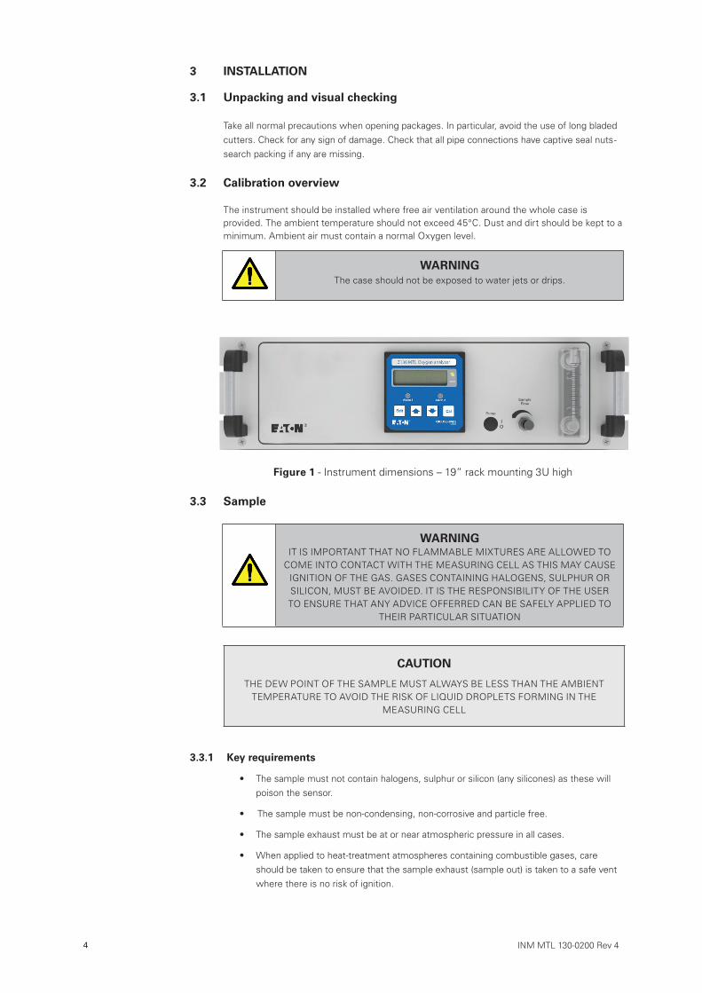
Figure 1 - Instrument dimensions – 19” rack mounting 3U high
3.3 Sample
WARNINGIT IS IMPORTANT THAT NO FLAMMABLE MIXTURES ARE ALLOWED TO
COME INTO CONTACT WITH THE MEASURING CELL AS THIS MAY CAUSE IGNITION OF THE GAS. GASES CONTAINING HALOGENS, SULPHUR OR SILICON, MUST BE AVOIDED. IT IS THE RESPONSIBILITY OF THE USER TO ENSURE THAT ANY ADVICE OFFERRED CAN BE SAFELY APPLIED TO
THEIR PARTICULAR SITUATION
CAUTION
THE DEW POINT OF THE SAMPLE MUST ALWAYS BE LESS THAN THE AMBIENT TEMPERATURE TO AVOID THE RISK OF LIQUID DROPLETS FORMING IN THE
MEASURING CELL
3.3.1 Key requirements
• The sample must not contain halogens, sulphur or silicon (any silicones) as these will poison the sensor.
• The sample must be non-condensing, non-corrosive and particle free.
• The sample exhaust must be at or near atmospheric pressure in all cases.
• When applied to heat-treatment atmospheres containing combustible gases, care should be taken to ensure that the sample exhaust (sample out) is taken to a safe vent where there is no risk of ignition.
INM MTL 130-0200 Rev 4 5
3.3.2 General advice Sample
The instrument is supplied with one of several sample system types specified by the user on order. A label on the instrument shows the pressure limits and other data for the particular one fitted. This should be taken into account before applying a sample.
WARNINGThe case should not be exposed to water jets or drips.
For permanently installed analysers it is advisable to fit an isolating valve in the sample delivery line so that the analyser can easily be removed for servicing. In cases where the sample exhaust is not vented to atmosphere then a valve may be required there too. The use of a three-way valve on the inlet side is also useful in allowing easy connection of other gases for calibration checks.
Dead-legs, particularly those present in Bourdon tube type pressure gauges and some fittings can take a long time to purge out as can small dead zones. Unnecessary dead-legs should be avoided.
Most analysers are supplied with a built-in sample flow-regulating valve. If a valve is fitted in the sample outlet pipe work it is important to remember that it must be the last to be shut.
3.3.3 Measuring low levels of oxygen
All piping should be of good quality material with sound joints and couplings. When measuring concentrations of less than 500ppm oxygen very small leakages can noticeably affect the readings- for ppm concentrations the piping must be of hard plastic or metal. Suitable plastics are Nylon and rigid P.V.C. Soft plastics, P.T.F.E. and flexible P.V.C. are not suitable. Cylinder pressure regulators should have a low volume and a metal diaphragm. Most pressure gauges etc. contain cavities that entrain air/oxygen and can take several hours to purge down, for this reason they should be avoided.
Flow regulating valves are typically poor shut-off valves and vice-versa. Multi-way valves can also be problematic, particularly if they have a source of pressurised high oxygen gas (air for instance) connected to one of their ports. If it is necessary to isolate a pressure regulator, a shut-off valve should be fitted to its outlet port.
If a pump is needed because the sample is at near atmospheric pressure, then it should be connected to the sample outlet and the sample drawn through the analyser, with the flow adjustment valve between the analyser outlet and the pump inlet. If the pump is placed at the sample inlet then it will need to be of a construction that will not contaminate the sample.
Flow meters can introduce leaks at these levels and should be installed in the sample outlet pipe work.
Before connecting a gas sample to the analyser it is advisable to thoroughly purge the external gas train.
6 INM MTL 130-0200 Rev 4
3.4 Electrical connections
3.4.1 Measuring low levels of oxygen
Power connections should be made to the instrument using the IEC lead supplied.
3.4.2 RS232 Connection
NOTE See also section 8: Communication Protocol
DCE (instrument) DTE (PC)
signal description 9W 25W 9W
GND Signal gnd 5 7 5
RX Data received by instrument 2 2 3
TX Data transmitted from instrument 3 3 2
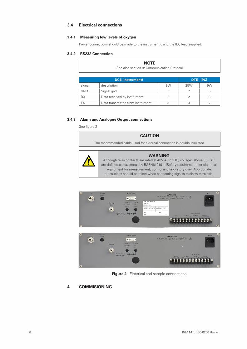
3.4.3 Alarm and Analogue Output connections
See figure 2
CAUTION
The recommended cable used for external connection is double insulated.
WARNINGAlthough relay contacts are rated at 48V AC or DC, voltages above 33V AC
are defined as hazardous by BSEN61010-1 (Safety requirements for electrical equipment for measurement, control and laboratory use). Appropriate
precautions should be taken when connecting signals to alarm terminals.
Figure 2 - Electrical and sample connections
4 COMMISIONING
INM MTL 130-0200 Rev 4 7
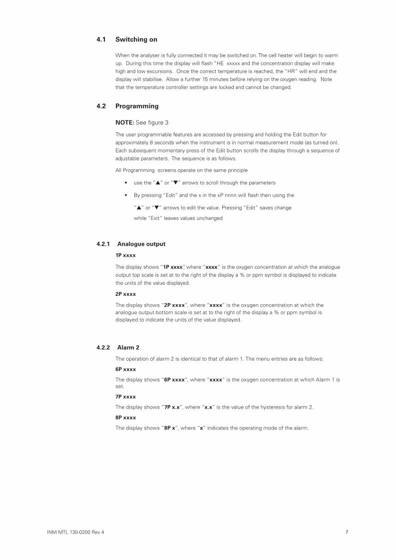
4.1 Switching on
When the analyser is fully connected it may be switched on. The cell heater will begin to warm up. During this time the display will flash “HE xxxxx and the concentration display will make high and low excursions. Once the correct temperature is reached, the “HR” will end and the display will stabilise. Allow a further 15 minutes before relying on the oxygen reading. Note that the temperature controller settings are locked and cannot be changed.
4.2 Programming
NOTE: See figure 3
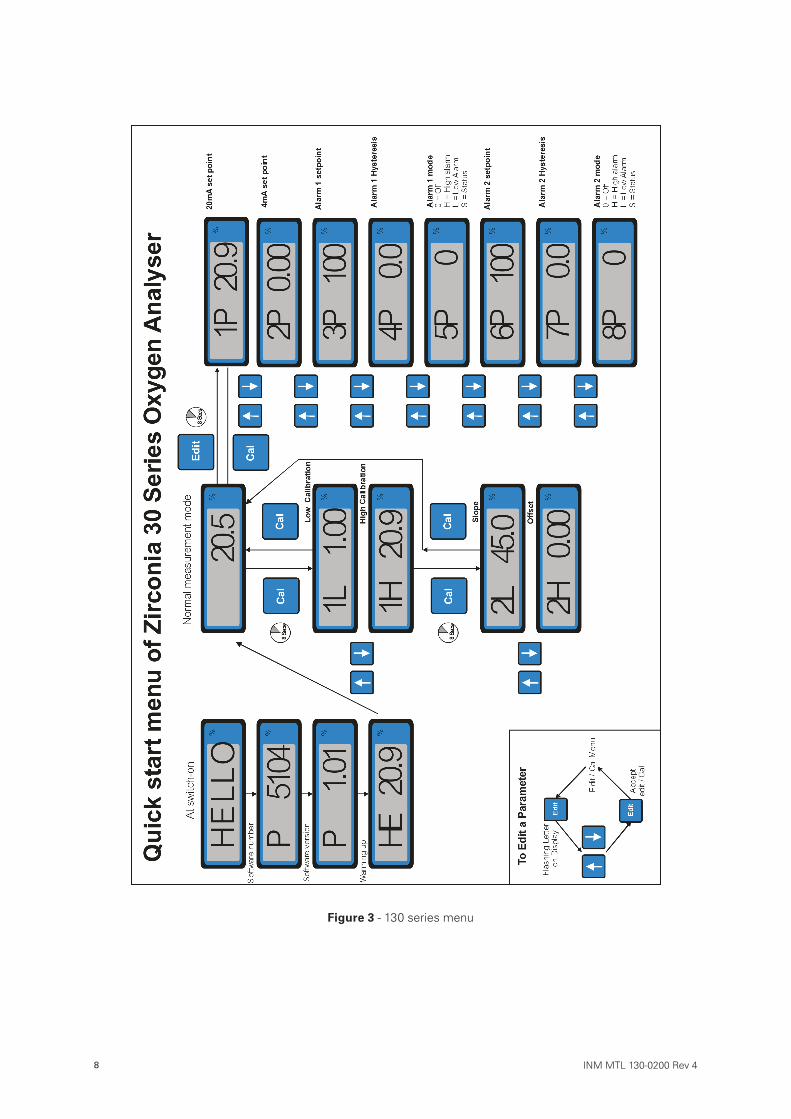
The user programmable features are accessed by pressing and holding the Edit button for approximately 8 seconds when the instrument is in normal measurement mode (as turned on). Each subsequent momentary press of the Edit button scrolls the display through a sequence of adjustable parameters. The sequence is as follows.
All Programming screens operate on the same principle
• use the “ ” or “ ” arrows to scroll through the parameters
• By pressing “Edit” and the x in the xP nnnn will flash then using the
“ ” or “ ” arrows to edit the value. Pressing “Edit” saves change
while “Exit” leaves values unchanged
4.2.1 Analogue output
1P xxxx
The display shows “1P xxxx”, where “xxxx” is the oxygen concentration at which the analogue output top scale is set at to the right of the display a % or ppm symbol is displayed to indicate the units of the value displayed.
2P xxxx
The display shows “2P xxxx”, where “xxxx” is the oxygen concentration at which the analogue output bottom scale is set at to the right of the display a % or ppm symbol is displayed to indicate the units of the value displayed.
4.2.2 Alarm 2
The operation of alarm 2 is identical to that of alarm 1. The menu entries are as follows:
6P xxxx
The display shows “6P xxxx”, where “xxxx” is the oxygen concentration at which Alarm 1 is set.
7P xxxx
The display shows “7P x.x”, where “x.x” is the value of the hysteresis for alarm 2.
8P xxxx
The display shows “8P x”, where “x” indicates the operating mode of the alarm.
8 INM MTL 130-0200 Rev 4
Figure 3 - 130 series menu
INM MTL 130-0200 Rev 4 9
5 CALIBRATION
CAUTION
Various procedures associated with calibration maintenance affect the outputs of the instrument. Any of these outputs that are being used for control (or the associated control
loop) should be disabled before commencing.
5.1 Calibration overview
The Z130 is a very stable analyser with a drift rate of better than 2% of reading per month. How often the calibration is checked or verified depends on the quality regime being operated at the installation site. Typically monthly checks are found to be adequate.
It is preferable to use a calibration technique that starts by checking or verifying the response of the analyser and only altering the calibration of the analyser if the errors are significant. The readings may be verified by introducing a gas mixture of known concentration (calibration gas), and checking that the reading is correct after allowing the system to stabilise.
A full calibration requires two standard gases to set two points that are equivalent to zero and span. (See section 7 for a technical description of the sensor and how it works). The gas calibration points are referred to as high(H) and low(L). It is usual, mainly because of convenience, to use air as the “high” gas. The “low” gas should ideally have approximately the same oxygen concentration as the normal sample
As with most instruments of this type it is important to have a reasonable concentration difference between the two calibration points. For the Z130 the recommended difference is 0.25 decades, i.e. LOG (H concentration/ L concentration) > ±0.25.
Because the most common high level gas is air, in order to maintain an adequate difference in concentration, the instrument will not accept a “low” level calibration gas between 10% and 40%.
5.2 Calibration gases
Because the sensor operates at high temperature, the calibration gases must not contain any flammable or reactive components. Typically this means using mixtures of oxygen with nitrogen. Refer to section 3.3 for sample connection and handling precautions.
Instrument grade compressed air (i.e. clean, dry and oil free) is frequently the most convenient gas to use for the upper concentration. Clean dry air has an oxygen content of 20.95%. If moist air is used then its water content must be allowed for. For example air at 20°C and 70% relative humidity (typical room air) contains 1.6% water. This will lower the oxygen content of the air by dilution to 20.6%.
It is important that the analyser IS NOT ZEROED in the conventional manner using a ‘zero’ grade gas. This is because the notion of zero oxygen has no real meaning for sensors of the type used in this analyser (See Section 7 – Technical description of sensor). We recommend that the standard gas contains at least 5ppm oxygen and
10 INM MTL 130-0200 Rev 4
only ppb levels of combustibles.
5.3 Calibration procedure
NOTE: see Figure 3
All calibration screens operate on the same principle :-
• The display shows the present reading. This may be changed by pressing
“Edit” and then using the “ ” or “ ” arrows to adjust the value.
• “Edit” saves change.
• “Cal” cancels the change.
5.3.1 ‘High point’ calibration
Expose the process side of the cell to air at normal ambient pressure.
Press and hold the “Cal” button for about 8 seconds until the display changes to show “1L xxxx”, where “xxxx” is the gas concentration measured by the instrument (if the button is released before the display changes then the analyser will remain in normal measuring mode).
Cycle through the menu entries using the “ ” or “ ” arrows until display shows “1H xxxx”
(pressing “ ” at the bottom of the menu returns you to the top).
When the reading has stabilised, press the “Edit” button and use the “ ” or “ ” arrows to adjust the reading to the correct level, then press the “Edit” button to store the calibration setting (or “Cal” to cancel).
To return the unit to measuring mode press and release the “Cal” button, otherwise the “” or “ ” arrows until the display changes to “L xxxx” to continue with setting the “Low”
calibration point.
5.3.2 ‘Low point’ calibration
Change the sample gas supply to the “Low” level concentration and establish a flow of the gas through the analyser.
In measuring mode, Press and hold the “Cal” button for about 8 seconds until the display changes to show “1L xxxx”.
In high point calibration, use the “ ” and “ ” arrows until the display changes to “L xxxx”.
When the reading has stabilised, press the “Edit” button and use the “ ” or “ ” arrows to adjust the reading to the correct level, then press the “Edit” button to store the calibration setting (or “Cal” to cancel).
With the calibration complete press and release the “Cal” button to return the unit to normal measuring mode.
NOTE
Calibration limits are set in the software that prevents the user from adjusting the readings too far away from where the sensor output would indicate. When these limits are reached
the displayed value will stop changing.
INM MTL 130-0200 Rev 4 11
6 MAINTENANCECalibration is the only routine operation that is necessary on a regular basis.
The Z130 is a very stable analyser with a drift rate of better than 2% of reading per month. How often the calibration is checked or verified depends on the quality regime being operated at the installation site. Typically monthly checks are found to be adequate.
WARNINGOpening the analyser case will expose you to mains voltage. Disconnect the analyser from the mains supply and any potentially hazardous process wiring
before opening the case.
6.1 Ordering parts
Should a failure occur, return the instrument to your local MTL Gas sales office for repair. When ordering spares or raising queries on the instrument, it is important to quote its serial number or job number. These numbers are on the data label located on the rear panel of the instrument.
Our contact details can be found on the back page of this manual.
12 INM MTL 130-0200 Rev 4
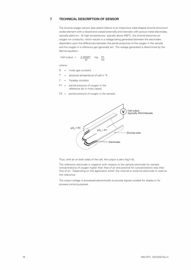
7 TECHNICAL DESCRIPTION OF SENSOR The zirconia oxygen sensor (see sketch below) is an impervious tube-shaped zirconia (zirconium oxide) element with a closed end coated externally and internally with porous metal electrodes, typically platinum. At high temperatures, typically above 400°C, the zirconia becomes an oxygen ion conductor, which results in a voltage being generated between the electrodes dependent upon the differences between the partial pressures of the oxygen in the sample and the oxygen in a reference gas (generally air). The voltage generated is determined by the Nernst equation:-
Cell output = 2.303RT log P14F P2
where:-
R = molar gas constant
T = absolute temperature of cell in °K
F = Faraday constant
P1 = partial pressure of oxygen in the reference (air in most cases)
P2 = partial pressure of oxygen in the sample.
Thus, with air on both sides of the cell, the output is zero (log1=0).
The reference electrode is negative with respect to the sample electrode for sample concentrations of oxygen higher than that of air and positive for concentrations less than that of air. Depending on the application either the internal or external electrode is used as the reference.
The output voltage is processed electronically to provide signals suitable for display or for process control purposes.
��������������������������� ��� �
�����������
������� ��
����������������
�
INM MTL 130-0200 Rev 4 13
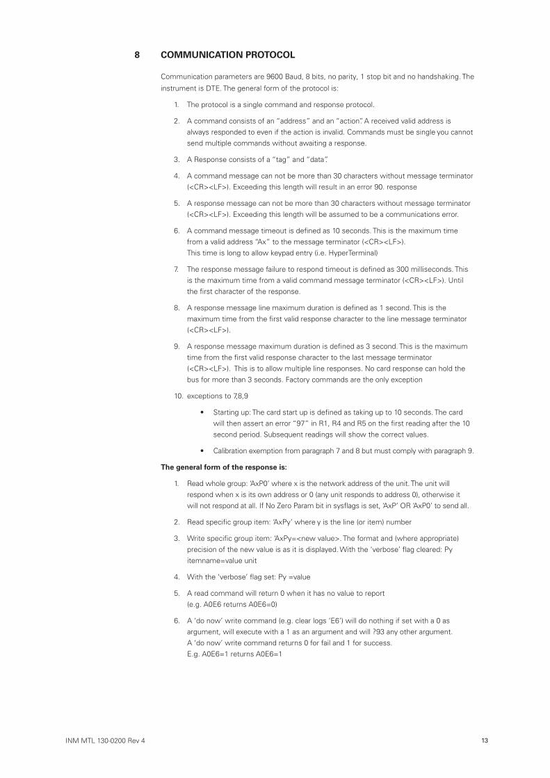
8 COMMUNICATION PROTOCOL
Communication parameters are 9600 Baud, 8 bits, no parity, 1 stop bit and no handshaking. The
instrument is DTE. The general form of the protocol is:
1. The protocol is a single command and response protocol.
2. A command consists of an “address” and an “action”. A received valid address is always responded to even if the action is invalid. Commands must be single you cannot send multiple commands without awaiting a response.
3. A Response consists of a “tag” and “data”.
4. A command message can not be more than 30 characters without message terminator (<CR><LF>). Exceeding this length will result in an error 90. response
5. A response message can not be more than 30 characters without message terminator (<CR><LF>). Exceeding this length will be assumed to be a communications error.
6. A command message timeout is defined as 10 seconds. This is the maximum time from a valid address “Ax” to the message terminator (<CR><LF>). This time is long to allow keypad entry (i.e. HyperTerminal)
7. The response message failure to respond timeout is defined as 300 milliseconds. This is the maximum time from a valid command message terminator (<CR><LF>). Until the first character of the response.
8. A response message line maximum duration is defined as 1 second. This is the maximum time from the first valid response character to the line message terminator (<CR><LF>).
9. A response message maximum duration is defined as 3 second. This is the maximum time from the first valid response character to the last message terminator (<CR><LF>). This is to allow multiple line responses. No card response can hold the bus for more than 3 seconds. Factory commands are the only exception
10. exceptions to 7,8,9
• Starting up: The card start up is defined as taking up to 10 seconds. The card will then assert an error “97” in R1, R4 and R5 on the first reading after the 10 second period. Subsequent readings will show the correct values.
• Calibration exemption from paragraph 7 and 8 but must comply with paragraph 9.
The general form of the response is:
1. Read whole group: ‘AxP0’ where x is the network address of the unit. The unit will respond when x is its own address or 0 (any unit responds to address 0), otherwise it will not respond at all. If No Zero Param bit in sysflags is set, ‘AxP’ OR ‘AxP0’ to send all.
2. Read specific group item: ‘AxPy’ where y is the line (or item) number
3. Write specific group item: ‘AxPy=<new value>. The format and (where appropriate) precision of the new value is as it is displayed. With the ‘verbose’ flag cleared: Py itemname=value unit
4. With the ‘verbose’ flag set: Py =value
5. A read command will return 0 when it has no value to report (e.g. A0E6 returns A0E6=0)
6. A ‘do now’ write command (e.g. clear logs ‘E6’) will do nothing if set with a 0 as argument, will execute with a 1 as an argument and will ?93 any other argument. A ‘do now’ write command returns 0 for fail and 1 for success. E.g. A0E6=1 returns A0E6=1
14 INM MTL 130-0200 Rev 4
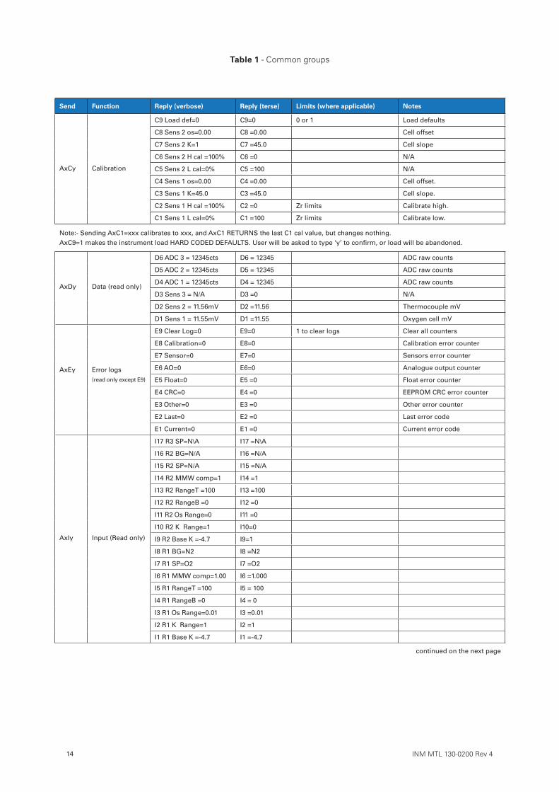
Table 1 - Common groups
Send Function Reply (verbose) Reply (terse) Limits (where applicable) Notes
AxCy Calibration
C9 Load def=0 C9=0 0 or 1 Load defaults
C8 Sens 2 os=0.00 C8 =0.00 Cell offset
C7 Sens 2 K=1 C7 =45.0 Cell slope
C6 Sens 2 H cal =100% C6 =0 N/A
C5 Sens 2 L cal=0% C5 =100 N/A
C4 Sens 1 os=0.00 C4 =0.00 Cell offset.
C3 Sens 1 K=45.0 C3 =45.0 Cell slope.
C2 Sens 1 H cal =100% C2 =0 Zr limits Calibrate high.
C1 Sens 1 L cal=0% C1 =100 Zr limits Calibrate low.
Note:- Sending AxC1=xxx calibrates to xxx, and AxC1 RETURNS the last C1 cal value, but changes nothing. AxC9=1 makes the instrument load HARD CODED DEFAULTS. User will be asked to type ‘y’ to confirm, or load will be abandoned.
AxDy Data (read only)
D6 ADC 3 = 12345cts D6 = 12345 ADC raw counts
D5 ADC 2 = 12345cts D5 = 12345 ADC raw counts
D4 ADC 1 = 12345cts D4 = 12345 ADC raw counts
D3 Sens 3 = N/A D3 =0 N/A
D2 Sens 2 = 11.56mV D2 =11.56 Thermocouple mV
D1 Sens 1 = 11.55mV D1 =11.55 Oxygen cell mV
AxEy Error logs (read only except E9)
E9 Clear Log=0 E9=0 1 to clear logs Clear all counters
E8 Calibration=0 E8=0 Calibration error counter
E7 Sensor=0 E7=0 Sensors error counter
E6 AO=0 E6=0 Analogue output counter
E5 Float=0 E5 =0 Float error counter
E4 CRC=0 E4 =0 EEPROM CRC error counter
E3 Other=0 E3 =0 Other error counter
E2 Last=0 E2 =0 Last error code
E1 Current=0 E1 =0 Current error code
AxIy Input (Read only)
I17 R3 SP=N\A I17 =N\A
I16 R2 BG=N/A I16 =N/A
I15 R2 SP=N/A I15 =N/A
I14 R2 MMW comp=1 I14 =1
I13 R2 RangeT =100 I13 =100
I12 R2 RangeB =0 I12 =0
I11 R2 Os Range=0 I11 =0
I10 R2 K Range=1 I10=0
I9 R2 Base K =-4.7 I9=1
I8 R1 BG=N2 I8 =N2
I7 R1 SP=O2 I7 =O2
I6 R1 MMW comp=1.00 I6 =1.000
I5 R1 RangeT =100 I5 = 100
I4 R1 RangeB =0 I4 = 0
I3 R1 Os Range=0.01 I3 =0.01
I2 R1 K Range=1 I2 =1
I1 R1 Base K =-4.7 I1 =-4.7
continued on the next page
INM MTL 130-0200 Rev 4 15
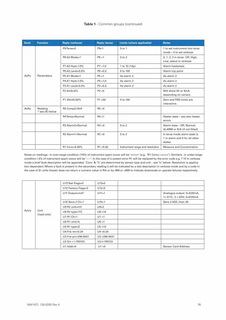
Table 1 - Common groups (continued)
Send Function Reply (verbose) Reply (terse) Limits (where applicable) Notes
AxPy Parameters.
P9 Terse=0 P9=1 0 or 1 1 to set instrument into terse mode – 0 to set verbose
P8 A2 Mode=1 P8 =1 0 to 3 0, 1, 2, 3 in terse - Off, High, Low, status in verbose
P7 A2 Hyst=1.0% P7 =1.0 1 to 10 (1dp) Alarm hysteresis
P6 A2 Level=5.0% P6 =5.0 0 to 100 Alarm trip point
P5 A1 Mode=1 P5 =1 As alarm 2 As alarm 2
P4 A1 Hyst=1.0% P4 =1.0 As alarm 2 As alarm 2
P3 A1 Level=5.0% P3 =5.0 As alarm 2 As alarm 2
P2 4mA=0% P2 =0 Will show 0V or 4mA depending on variant.
P1 20mA=50% P1 =50 0 to 100 Zero and FSD limits are interactive.
AxRy Reading * see (8) below
R5 Comp2=N/A R5 =0
R4 Temp=Normal R4 =1 Heater state – see also heater errors.
R3 Alarm2=Normal R3 =0 0 to 2 Alarm state – Off, Normal, ALARM or N/A (if not fitted)
R2 Alarm1=Normal R2 =0 0 to 2 In terse mode alarm state is 1 in alarm and 0 for all other states
R1 Conc=5.00% R1 =5.00 Instrument range and resolution Measure and Concentration
Notes on readings:- In over-range condition (110% of instrument span) xxxxx will be ‘+++++’ (e.g. ‘R1 Conc= +++++’). Similarly in under-range condition (-5% of instrument span) xxxxx will be ‘-----’. In the case of a system error R1 will be replaced by the error code e.g. ? 72 In verbose mode a brief fault description will be appended. ‘Conc’ & ‘%’ are determined by sensor type and unit – see ‘U’ below. Resolution is applica-tion dependant. Where a fault is present in the secondary reading it will be indicated by a text description in verbose mode and by a code in the case of Zr units (heater does not return a numeric value in R4) or by -999 or +999 to indicate downscale or upscale failures respectively.
AxUy Unit (read only)
U13 Test Flags=0 U13=0
U12 Factory Flags=0 U12=0
U11 Output=mA* U11=1 Analogue output: 0=4/20mA, 1= 0/1V, 2 = 0/5V, 3=0/20mA
U10 Sens 2 Ch=1 U10=1 Sens 2 ADC chan (9)
U9 R2 unit=mV U9=2
U8 R2 type=T/C U8 =14
U7 R1 Ch=1 U7 =1
U6 R1 unit=% U6 =1
U5 R1 type=Z U5 =13
U4 F/w rev=0.24 U4 =0.24
U3 F/w p/n=290-6031 U3 =290-6031
U2 S/n = I-700123 U2=I-700123
U1 Addr=0 U1 =0 Sensor Card Address
16 INM MTL 130-0200 Rev 4
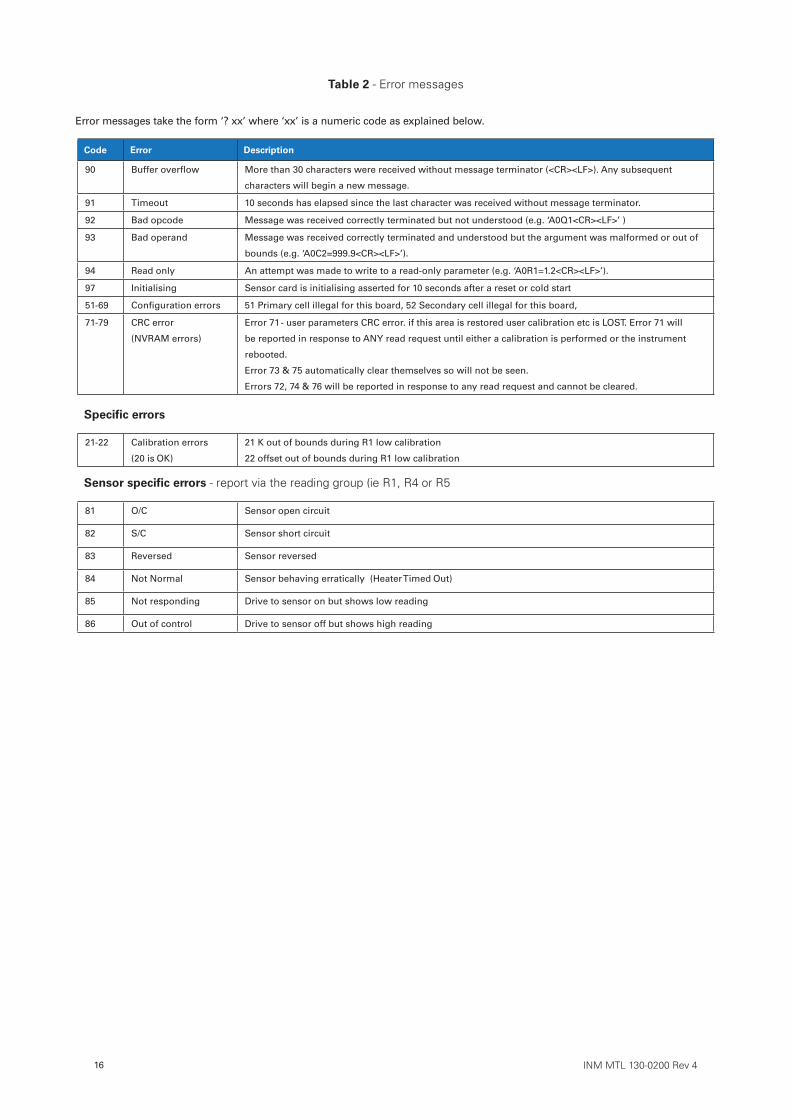
Code Error Description
90 Buffer overflow More than 30 characters were received without message terminator (<CR><LF>). Any subsequent
characters will begin a new message.
91 Timeout 10 seconds has elapsed since the last character was received without message terminator.
92 Bad opcode Message was received correctly terminated but not understood (e.g. ‘A0Q1<CR><LF>’ )
93 Bad operand Message was received correctly terminated and understood but the argument was malformed or out of
bounds (e.g. ‘A0C2=999.9<CR><LF>’).
94 Read only An attempt was made to write to a read-only parameter (e.g. ‘A0R1=1.2<CR><LF>’).
97 Initialising Sensor card is initialising asserted for 10 seconds after a reset or cold start
51-69 Configuration errors 51 Primary cell illegal for this board, 52 Secondary cell illegal for this board,
71-79 CRC error
(NVRAM errors)
Error 71 - user parameters CRC error. if this area is restored user calibration etc is LOST. Error 71 will
be reported in response to ANY read request until either a calibration is performed or the instrument
rebooted.
Error 73 & 75 automatically clear themselves so will not be seen.
Errors 72, 74 & 76 will be reported in response to any read request and cannot be cleared.
Specific errors
21-22 Calibration errors
(20 is OK)
21 K out of bounds during R1 low calibration
22 offset out of bounds during R1 low calibration
Sensor specific errors - report via the reading group (ie R1, R4 or R5
81 O/C Sensor open circuit
82 S/C Sensor short circuit
83 Reversed Sensor reversed
84 Not Normal Sensor behaving erratically (Heater Timed Out)
85 Not responding Drive to sensor on but shows low reading
86 Out of control Drive to sensor off but shows high reading
Table 2 - Error messages
Error messages take the form ‘? xx’ where ‘xx’ is a numeric code as explained below.

INM MTL 130-0200 Rev 4 17
THIS PAGE IS LEFT INTENTIONALLY BLANK

18 INM MTL 130-0200 Rev 4
THIS PAGE IS LEFT INTENTIONALLY BLANK

INM MTL 130-0200 Rev 4 19
THIS PAGE IS LEFT INTENTIONALLY BLANK
DRAFT - 27 November 2014
AUSTRALIAMTL Instruments Pty Ltd, 10 Kent Road, Mascot, New South Wales, 2020, Australia
Tel: +61 1300 308 374 Fax: +61 1300 308 463E-mail: [email protected]
BeNeLuxMTL Instruments BVAmbacht 6, 5301 KW ZaltbommelThe Netherlands
Tel: +31 (0) 418 570290 Fax: +31 (0) 418 541044E-mail: [email protected]
CHINACooper Electric (Shanghai) Co. Ltd955 Shengli Road, Heqing Industrial ParkPudong New Area, Shanghai 201201
Tel: +86 21 2899 3817 Fax: +86 21 2899 3992E-mail: [email protected]
FRANCEMTL Instruments sarl,7 rue des Rosiéristes, 69410 Champagne au Mont d’OrFrance
Tel: +33 (0)4 37 46 16 53 Fax: +33 (0)4 37 46 17 20E-mail: [email protected]
GERMANYMTL Instruments GmbH, Heinrich-Hertz-Str. 12, 50170 Kerpen, Germany
Tel: +49 (0)22 73 98 12 - 0 Fax: +49 (0)22 73 98 12 - 2 00E-mail: [email protected]
INDIAMTL India, No.36, Nehru Street, Off Old Mahabalipuram RoadSholinganallur, Chennai - 600 119, India
Tel: +91 (0) 44 24501660 /24501857 Fax: +91 (0) 44 24501463E-mail: [email protected]
ITALYMTL Italia srl, Via San Bovio, 3, 20090 Segrate, Milano, Italy
Tel: +39 02 959501 Fax: +39 02 95950759E-mail: [email protected]
JAPANCooper Crouse-Hinds Japan KK, MT Building 3F, 2-7-5 Shiba Daimon, Minato-ku,Tokyo, Japan 105-0012
Tel: +81 (0)3 6430 3128 Fax: +81 (0)3 6430 3129E-mail: [email protected]
NORWAYNorex ASFekjan 7c, Postboks 147, N-1378 Nesbru, Norway
Tel: +47 66 77 43 80 Fax: +47 66 84 55 33E-mail: [email protected]
RUSSIACooper Industries Russia LLCElektrozavodskaya Str 33Building 4Moscow 107076, Russia
Tel: +7 (495) 981 3770 Fax: +7 (495) 981 3771E-mail: [email protected]
SINGAPORECooper Crouse-Hinds Pte LtdNo 2 Serangoon North Avenue 5, #06-01 Fu Yu BuildingSingapore 554911
Tel: +65 6645 9864 / 6645 9865 Fax: +65 6 645 9865E-mail: [email protected]
SOUTH KOREACooper Crouse-Hinds Korea7F. Parkland Building 237-11 Nonhyun-dong Gangnam-gu,Seoul 135-546, South Korea.
Tel: +82 6380 4805 Fax: +82 6380 4839E-mail: [email protected]
UNITED ARAB EMIRATESCooper Industries/Eaton Corporation Office 205/206, 2nd Floor SJ Towers, off. Old Airport Road, Abu Dhabi, United Arab Emirates
Tel: +971 2 44 66 840 Fax: +971 2 44 66 841E-mail: [email protected]
UNITED KINGDOMEaton Electric Limited, Great Marlings, Butterfield, LutonBeds LU2 8DL
Tel: +44 (0)1582 723633 Fax: +44 (0)1582 422283E-mail: [email protected]
AMERICASCooper Crouse-Hinds MTL Inc. 3413 N. Sam Houston Parkway W.Suite 200, Houston TX 77086, USA
Tel: +1 281-571-8065 Fax: +1 281-571-8069E-mail: [email protected]
The given data is only intended as a product description and should not be regarded as a legal warranty of properties or guarantee. In the interest of further technical developments, we reserve the right to make design changes.
EUROPE (EMEA):
+44 (0)1582 723633 [email protected]
THE AMERICAS:
+1 800 835 7075 [email protected]
ASIA-PACIFIC:
+65 6645 9864 / 9865 [email protected]
Eaton Electric Limited, Great Marlings, Butterfield, LutonBeds, LU2 8DL, UK.Tel: + 44 (0)1582 723633 Fax: + 44 (0)1582 422283E-mail: [email protected] © 2017 Eaton All Rights ReservedPublication No. INM MTL 130-0200 Rev 4 140217February 2017