mu-troniii - schems.comschems.com/bmampscom/effects_misc/mu-tron iii_om_sch.pdf · mu-troniii...
TRANSCRIPT
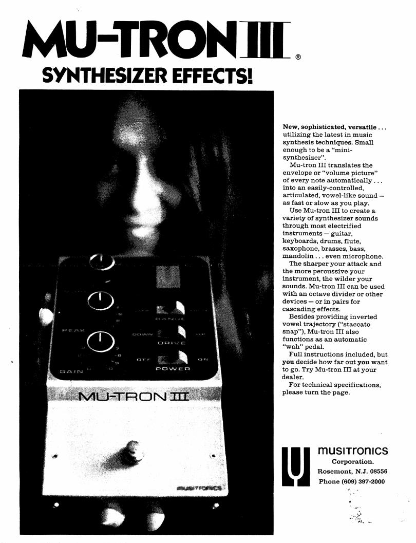
MU-TRONIIISYNTHESIZER EFFECTS!
New, sophisticated, versatile ...
utilizing the latest in music
synthesis techniques. Small
enough to be a "mini-
synthesizer".
Mu-tron III translates the
envelope or "volume picture"
of every note automatically...
into an easily-controlled,
articulated, vowel-like sound —
as fast or slow as you play.
Use Mu-tron III to create a
variety of synthesizer sounds
through most electrified
instruments — guitar,
keyboards, drums, flute,
saxophone, brasses, bass,
mandolin ... even microphone.
The sharper your attack and
the more percussive your
instrument, the wilder your
sounds. Mu-tron III can be used
with an octave divider or other
devices — or in pairs for
cascading effects.
Besides providing inverted
vowel trajectory ("staccato
snap"), Mu-tron III also
functions as an automatic
"wah" pedal.
Full instructions included, but
you decide how far out you want
to go. Try Mu-tron III at your
dealer.
For technical specifications,
please turn the page.
L'JmusiTronics
Corporation.
Rosemont, N.J. 08556
Phone (609) 397-2000
.. "7k -
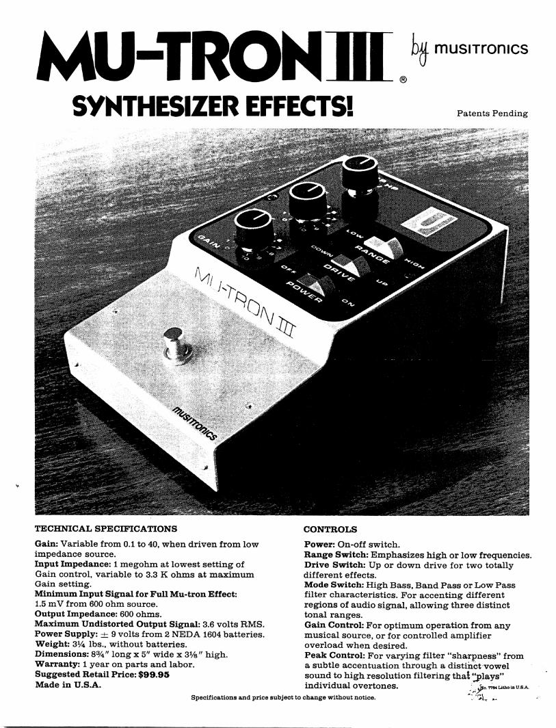
MU-TRONIIISYNTHESIZER EFFECTS!
musiTronics
Patents Pending
TECHNICAL SPECIFICATIONS
Gain: Variable from 0.1 to 40, when driven from low
impedance source.
Input Impedance: 1 megohm at lowest setting of
Gain control, variable to 3.3 K ohms at maximum
Gain setting.
Minimum Input Signal for Full Mu-tron Effect:
1.5 mV from 600 ohm source.
Output Impedance: 600 ohms.
Maximum Undistorted Output Signal: 3.6 volts RMS.
Power Supply: ± 9 volts from 2 NEDA 1604 batteries.
Weight: 3AA lbs., without batteries.
Dimensions: 8%" long x 5" wide x 3%" high.
Warranty: 1 year on parts and labor.
Suggested Retail Price: $99.95
Made in U.S.A.
CONTROLS
Power: On-off switch.
Range Switch: Emphasizes high or low frequencies.
Drive Switch: Up or down drive for two totally
different effects.
Mode Switch: High Bass, Band Pass or Low Pass
filter characteristics. For accenting different
regions of audio signal, allowing three distinct
tonal ranges.
Gain Control: For optimum operation from any
musical source, or for controlled amplifier
overload when desired.
Peak Control: For varying filter "sharpness" from
a subtle accentuation through a distinct vowel
sound to high resolution filtering that Splays"
individual overtones. j,o. 7784utho m t
Specifications and price subject to change without notice.
IMPORTANT NOTE CONCERNING DATTERIES:
The first indication of battery failure will be a reduction or
Icst of ihr» "Wah" effect, which may or may not be accompanied by a
high frequency oscillation. Always try new batteries before assuminq
that your Mu-tron is defective, keeping in mind the following:
Due to unequal current drain during operation, the useful life
ci the battery in the holder with the red lead is considerably
:.. ',r\rr Khnn th*t of the battery in the holder with the black lead.
t-yj should he able to repl*c» cniy the battery in the holder
ri**. tf.e red lead at least two or three times before both batteries
?49n*nfc"?rf h',vr/<r, that if the Kj-troo is accidentally left with
•.-• PV*ZP switch in its C'f position, particularly if the DPIVE switch
Is in *•-.- DOW position, battery life will be short.
We recorrend the use of alkaline type batteries in this product,
especially in the holder with the red lead.
In order to avoid noisy or intermittent connections between the
battery terminals and battery holder contacts, remove weak batteries
by lifting straight up from the rear of the battery without any side
to side rocking motion which might spread the "♦•• or female contact
of the holder. Should these contacts ever become loose or noisy,
close them together slightly with a pliers.
USE WITH MOOEL PS-1 BATTERY ELIMINATOR
A 3-pin socket located on the rear of your Mu-tron will accept
the output of the MODEL PS-1. When using the PS-1, it is best to
remove the batteries from the Mu-tron. Batteries left in the holder
will be charged by the PS-1 whenever it is connected to the power line
and the Mu-tron. Should the batteries already be fully charged, there
is some danger of leakage or even damage to the battery cases taking
place.
TECHNICAL SPECIFICATIONS:
GAIN: Variable from 0.1 to 40, when driven from low impedance
source.
INPUT IMPEDANCE: 1 Megohm at lowest setting of GAIN control,
variable to 3.3K ohms at maximum gain setting.
MINIMUM INPUT SIGNAL FOR FULL MU-TRON EFFECT: 1.5mV from 600
ohm source.
OUTPUT IMPEDANCE: 600 ohms
MAXIMUM UNDISTORTED OUTPUT SIGNAL: 3.6 volts RMS
POWER SUPPLY: ± 9 Volts from 2 NEDA 1604 batteries or Musitronics
Model PS-1 Artery Eliminator.
L'J
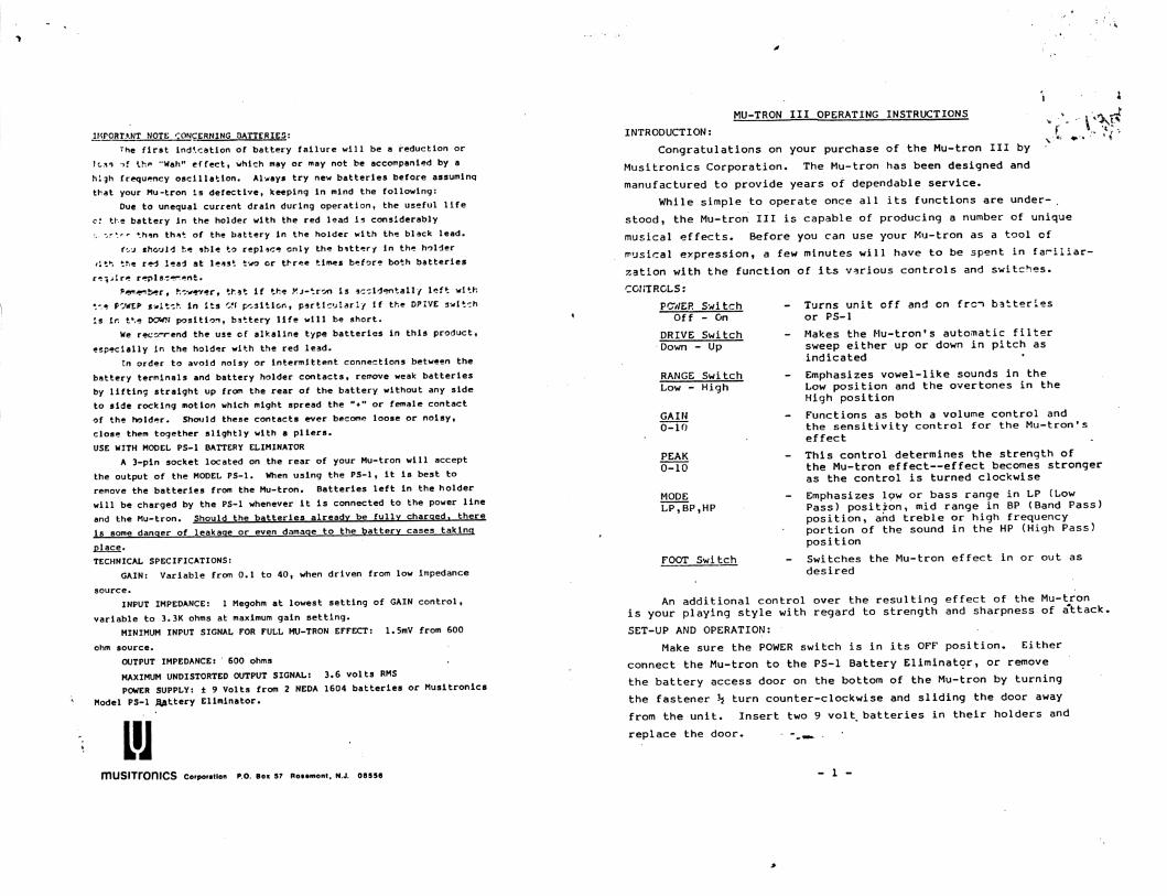
MU-TRON III OPERATING INSTRUCTIONS . ^
INTRODUCTION: f V >
Congratulations on your purchase of the Mu-tron III by
Musitronics Corporation. The Mu-tron has been designed and
manufactured to provide years of dependable service.
While simple to operate once all its functions are under-,
stood, the Mu-tron III is capable of producing a number of unique
musical effects. Before you can use your Mu-tron as a tool of
musical expression, a few minutes will have to be spent in fariliar-
zation with the function of its various controls and switches.
CONTROLS:
- Turns unit off and on frcn batteries
or PS-1
- Makes the Mu-tronfs automatic filter
sweep either up or down in pitch as
indicated
Emphasizes vowel-like sounds in the
Low position and the overtones in the
High position
Functions as both a volume control and
the sensitivity control for the Mu-tronfs
effect
- This control determines the strength of
the Mu-tron effect—effect becomes stronger
as the control is turned clockwise
Emphasizes low or bass range in LP (Low
Pass) position, mid range in BP (Band Pass)position, and treble or high frequency
portion of the sound in the HP (High Pass)
position
- Switches the Mu-tron effect in or out as
desired
PC7/ER
Off
DRIVE
Down -
RANGE
Low -
GAIN
0-10
PEAK
0-10
MODE
LP,BP
Switch
- On
Switch
- Up
Switch
High
• HP
FOOT Switch
Corporation P.O. Bo* 57 Ro«»mont, N.J. 08556
An additional control over the resulting effect of the Mu-tron
is your playing style with regard to strength and sharpness of attack.
SET-UP AND OPERATION:
Make sure the POWER switch is in its OFF position. Either
connect the Mu-tron to the PS-1 Battery Eliminator, or remove
the battery access door on the bottom of the Mu-tron by turning
the fastener h turn counter-clockwise and sliding the door away
from the unit. Insert two 9 volt, batteries in their holders and
replace the door. -mw.-
- 1 -
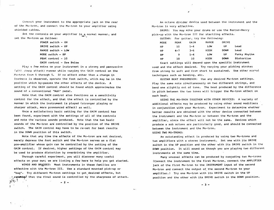
Connect your instrument to the appropriate jack on the rear
of tho Mu-tron, and connect the Mu-tron to your amplifier using
shielded cables.
Sot the controls on your amplifier in a normal manner, and
set the Mu-tron as follows:
POWER switch - ON
DRIVE switch - UP
RANGE switch - LOW
MODE switch - BP
PEAK control - 10
GAIN control - See Below
Play o few notes on yo'jr instrument in a strong and percussive
(wit.*-. :;h*rp attack) manner while varying the GAIN control on the
tfu-trcn from 0 through 5. If no effect other than a change in
loudness is observed, operate the foot sv/itch, which may be in the
position which by-passes the other effects of the device. A
setting of the GAIN control should be found which approximates the
sound of a conventional "Wan" pedal.
Note that the GAIN control also functions as a sensitivity
control for the effect, and that the effect is controlled by the
manner in which the instrument is played (stronger playing or
sharper attack, more pronounced effect) as well.
Once a satisfactory basic setting for the GAIN control has
been found, experiment with the settings of all of the controls
and note the various sounds produced. Note that the two basic
sounds of the Mu-tron are controlled by the position of the DRIVE
switch. The GAIN control may have to be re-set for best results
in the DOWN position of this switch.
Note that any time the effects of the Mu-tron are not desired,
merely depress the foot switch and the Mu-tron serves as a flat
pre-amplifier whose gain can be controlled by the setting of the
GAIN control. If desired, higher settings of the GAIN control may
be used to produce distortion by overdriving the amplifier.
Through careful experiment, you will discover many useful
effects on your own; we are listing a few here to help you get started.
WINDS AND BRASSES: Most instruments in these families are
effective with the Mu-tron III. Use a standard mounted pick-up or
"bug". Try different Mu-tron settings to get desired effects, but
, ^ remetnber that the final sound is controlled by the sharpness of attack.
^ /,'t ' \
An octave divider device used between the instrument and the
Mu-tron is very effective.
DRUMS: You may mike your drums or use the Barcus-Berry
pick-up with the Mu-tron III for startling effects.
GUITAR: For guitar, try the following:
MODE PEAK GAIN RANGE DRIVE
HP 10 1-4 LOW UP Lead
HP 4-7 3-6 HIGH DOWN Lead
BP 9 1-4 LOW UP Funky Rhythm
HP 10 10 HIGH DOWN Distortion
Exact settings will depend upon the specific instrument
used and the effect desired. Try varying your picking strokes
from strong to soft and from short to sustained. Use other ncrnal
techniques such as bending, etc.
GUITAR BEAT PHENOMENON: Use any desired Mu-tron settings.
Play the same note simultaneously on two different strings, and
bend one slightly out of tune. The beat produced by the difference
in pitch between the two tones will trigger the Mu-tron effect on
each beat.
USING THE MU-TRON TOGETHER WITH OTHER DEVICES: A variety of
additional effects may be produced by using other sound modifiers
in conjunction with your Mu-tron. Experiment to determine whether
better results are obtained with the other device connected between
the instrument and the Mu-tron or between the Mu-tron and the
amplifier, since the effect will not be the same. Devices which
produce a sub octave are particularly good, and should be connected
between the instrument and the Mu-tron.
USING TWO MU-TRONS:
An outstanding effect is produced by using two Mu-trons and
two amplifiers with a stereo instrument. Set one with its DRIVE
switch in the UP position and the other with its DRIVE switch in the
DOWN position. It will sound as though you are playing two different
instruments at the same time.
Many unusual effects can be produced by cascading two Mu-trons
(Connect the instrument to the first Mu-tron, connect the AMPLIFIER
jack of the first Mu-tron to the INSTRUMENT input of the second
Mu-tron and connect the output of. the second Mu-tron to your
amplifier.) Try one Mu-tron with its DRIVE switch in the UP
position and the other with its DRIVE switch in the DOWN position.
- 3- -
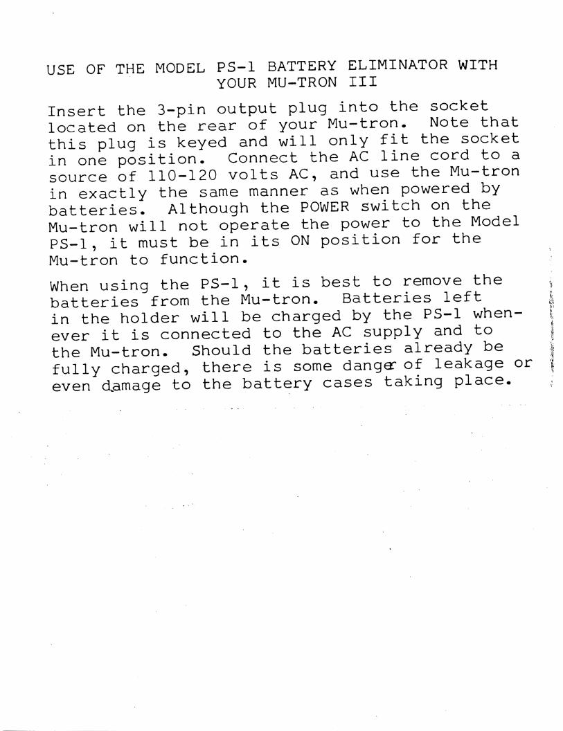
USE OF THE MODEL PS-1 BATTERY ELIMINATOR WITH
YOUR MU-TRON III
Insert the 3-pin output plug into the socketlocated on the rear of your Mu-tron. Note that
this plug is keyed and will only fit the socketin one position. Connect the AC line cord to a
source of 110-120 volts AC, and use the Mu-tron
in exactly the same manner as when powered bybatteries. Although the POWER switch on the
Mu-tron will not operate the power to the ModelPS-1, it must be in its ON position for the
Mu-tron to function.
When using the PS-1, it is best to remove the ,batteries from the Mu-tron. Batteries left |in the holder will be charged by the PS-1 when- iever it is connected to the AC supply and to §the Mu-tron. Should the batteries already be |
fully charged, there is some danger of leakage or |
even damage to the battery cases taking place. .
KU-TRON, Incorporated
£5 liartwell Avenue
Lexington, Massachusetts, 02173
Telephone: 617/861-6000
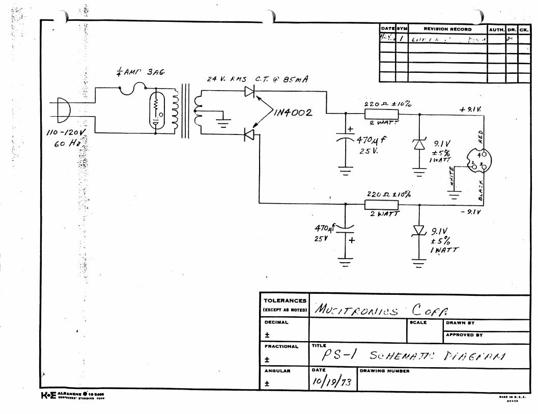
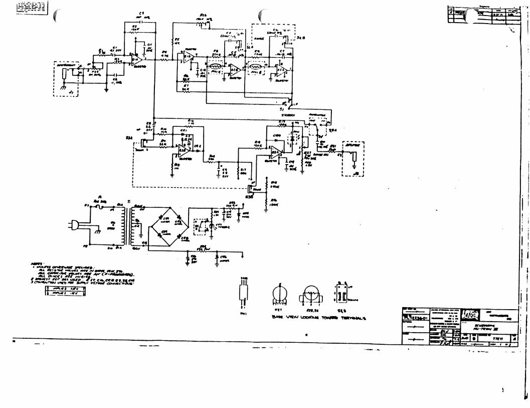
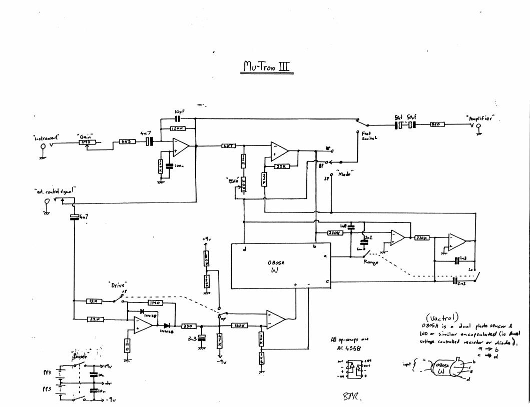
THE MU-TRON III
Since the Mu-tron effects devices are quite simple in
comparison to the much larger ARP synthesizers, we are not
including all the detailed instruction that goes into the
ARP service manuals. You will find herewith the necessary
schematics, assembly drawings and parts lists, should you
have any questions, please call the ARP Service Department
at (617) 861-6000.
J-TROh
MU-TRON, Incorporated
45 Hartweii Avenue
Lexington, Massachusetts. 02173
Telephone: 617/861-6000
TERENCE
\1
17
G
15
,2,
.4,
,6
,10
r8,9
,2,3
!5
!6
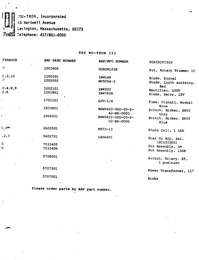
ARP PART NUMBER
1001602
1200301
1202002
1202101
1201901
1701101
1903901
1904001
2602501
5602701
7533405
7533406
5708001
5707301
5707001
THE MU-TRON III
ARP/MFG NUMBER
U260R103B
1N4148
MV5054-2
1N4002
1N4742A
GJV-1/4
RSW0422-OSD-00-P-
A2-BK-0000
RSW0422-0SD-00-P-
U2-BK-0000
P873-13
1406401
DESCRIPTICN
Pot# Rotary Trimmer 10
Diode, Signal
Diode, Light emitting,
Red
Rectifier, 100V
Diode, Zer.er, 12V
Fuse, Pigtail, Normal
Blow
Svitch, Rccker, DPDT
Gray
Svitch, Rocker, DPDT
Blue
Photo Cell, 1 LED
l>jal Op Azp, Sel.
(RC455BK3)
Pot Assesibly, 1M
Pot Assemhly, 150K
Switch, Rc.ary, SP,
3 position
Power Transformer, 117
Knobs
Please order parts by ARP part number.
' I'
-MU-TRON, Incorporated
45 Hartvt'ell Avenue
Lexington, Massachusetts, 02173
>.U-TRON Telephone: 617/861-6000
Kusitronics Bi-PKASE
ARP PART NUMBER ARP/MFG PART NUMBER
5707101
5707201 •
1001901
1001902
1001904
1903S01
5708001
1903901
1904001
1904401
1903701
5708301
1305701
1200301
1202101
2502401
2602901
12C2001
1410101
5502701
1700901
5708601
5708501
CTS type VDT450
CTS type VDT450
Brel (Mfg.)
RSW422-SD-P-R1-BK
212-1
RSW422-SD-P-A2-BK
RSW422-SD-P-U2-BK
8174K11X121T50
112-P
2N4401
1N4148
1N4002
P653-G50-6
P873-12
MV5054-1
RC4195TK
RC455SNB
312.001
AR-3-M-L
AR-1-B-SK-M
(No references given)
DESCRIPTION
Pot, 10K, Linear
Pot, 25K, Clockwise log taper
Trim Pot, 10K, 3 terminal, horiz. mtg.
Trim Pot, IK,
Trim Pot, 22K
Rocker Switch DPDT, Red
Rotary Switch, SP3T
Rocker Switch DPDT, Gray
Rocker Switch, DPDT, Blue
Rocker Switch, power, illuminated
Footswitch S?DT
Power transformer, 117VAC
Transistor NPN
Diode, Signal
Rectifier, 1A
Photo cell
Photo cell
LED
IC, Voltage Regulator
IC, Dual Op Amp, Selected
Fuse, lAmp
Knob
Knob'
M
% ffi
H
l
•2, r
ft.
N
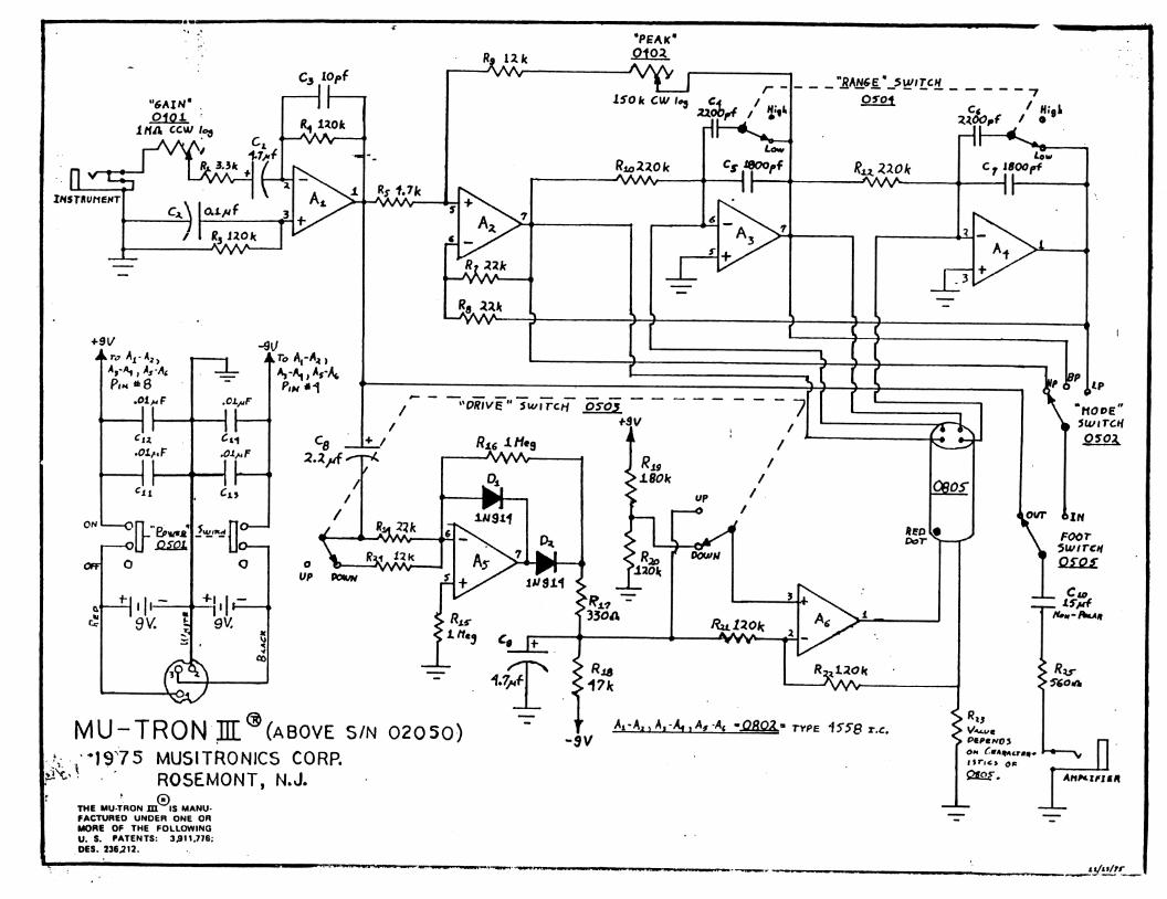
MU-TRON IH (above s/n 02050)
•1975 MUSITRONICS CORP.
1 ' ROSEMONT, N.J.
„©.THE MU-TRON HI IS MANU
FACTURED UNOER ONE OR
MORE OF THE FOLLOWING
U. S. PATENTS: 3J911.776;
OES. 236,212.