mu uuuu ui iiui iiui mii uui um uui imi iuu umi uu uii mi · mu uuuu ui iiui iiui mii uui um uui...
TRANSCRIPT

mu uuuu ui iiui iiui mii uui um uui imi iuu umi uu uii mi
(12) United States PatentHahn et al.
(54) AIRCRAFT WING FOR OVER-THE-WINGMOUNTING OF ENGINE NACELLE
(75) Inventors: Andrew S. Hahn, Yorktown, VA (US);David J. Kinney, Manteca, CA (US)
(73) Assignee: The United States of America asrepresented by the Administrator ofthe National Aeronautics and SpaceAdministration, Washington, DC (US)
(*) Notice: Subject to any disclaimer, the term of thispatent is extended or adjusted under 35U.S.C. 154(b) by 652 days.
(21) Appl. No.: 11/954,452
(22) Filed: Dec. 12, 2007
(65) Prior Publication Data
US 2009/0127405 Al May 21, 2009
Related U.S. Application Data
(60) Provisional application No. 60/870,634, filed on Dec.19, 2006.
(51) Int. Cl.B64C 39100 (2006.01)B64D 27100 (2006.01)
(52) U.S. Cl . ....................... 244/45 R; 244/55; 244/12.5(58) Field of Classification Search ................ 244/12.1,
244/13, 4 R, 23 R, 34 R, 35 R, 45 R, 55,244/12.5, 23 D, 36, 46; D12/341
See application file for complete search history.
(56) References Cited
U.S. PATENT DOCUMENTS
D140,302 S * 2/1945 Heinemann ................ D12/341
(lo) Patent No.: US 7,883,052 B2(45) Date of Patent: Feb. 8, 2011
D232,927 S * 9/1974 Blattner ..................... D12/3374,036,452 A 7/1977 SchairerD256,906 S * 9/1980 Conroy ...................... D12/341
4,398,683 A * 8/1983 Schmetzer ................. 244/12.54,447,028 A * 5/1984 Wang ......................... 244/212
4,449,680 A 5/1984 Gratzer et al.4,449,681 A 5/1984 Gratzer et al.4,482,108 A * 11/1984 Sutton ....................... 244/12.4
5,135,185 A 8/1992 Adamson et al.6,102,328 A 8/2000 Kumata et al.6,308,913 B1 10/2001 Fujinoetal.
OTHER PUBLICATIONS
D.J.Kinney et al. in "Comparison of Low and High Nacelle SubsonicTransport Configurations," American Institute of Aeronautics andAstronautics, AIAA 1997-2318, (1997) pp. 806-819.
* cited by examiner
Primary Examiner Joshua J Michener(74) Attorney, Agent, or Firm Andrea Z. Warmbier; RobinW. Edwards
(57) ABSTRACT
An aircraft wing has an inboard section and an outboard
section. The inboard section is attached (i) on one side thereofto the aircraft's fuselage, and (ii) on an opposing side thereofto an inboard side of a turbofan engine nacelle in an over-the-wing mounting position. The outboard section's leading edgehas a sweep of at least 20 degrees. The inboard section'sleading edge has a sweep between —15 and +15 degrees, andextends from the fuselage to an attachment position on thenacelle that is forward of an index position defined as animaginary intersection between the sweep of the outboardsection's leading edge and the inboard side of the nacelle. Inan alternate embodiment, the turbofan engine nacelle isreplaced with an open rotor engine nacelle.
24 Claims, 8 Drawing Sheets
100A
22A
100 I100C 15°
100D w
20 1008
^^ II
24A1I
100B-
24 —JJ 22 .--"
24B 22B 200
202
https://ntrs.nasa.gov/search.jsp?R=20110006855 2018-07-18T14:40:33+00:00Z

U.S. Patent Feb. 8, 2011 Sheet 1 of 8 US 7,883,052 B2
Fig. 1 A(Prior Art)
10
14 --'" 10B
Fig. 1 B(Prior Art)

U.S. Patent
Feb. 8, 2011 Sheet 2 of 8 US 7,883,052 B2
70 -%
14A---,
14 -^14B
100A100F
100E100 12A
Arir100D I
rrr
r i i
1000
ii
1008ii
J'?
12B 200
202
Fig. 2
100B100
1000100A
200
100D 100E
12
Fig. 3
14

U.S. Patent Feb. 8, 2011 Sheet 3 of 8 US 7,883,052 B2
a ^^ A r) r) A
Fig. 4

U.S. Patent Feb. 8, 2011 Sheet 4 of 8 US 7,883,052 B2
-1 nnu
GVL.
Fig. 5

U.S. Patent Feb. 8, 2011 Sheet 5 of 8 US 7,883,052 B2
Fig. 6

U.S. Patent
Feb. 8, 2011 Sheet 6 of 8 US 7,883,052 B2
f ^
400200 ^►
400C
t400D 400E
e 42
1 Ar
44
40
Fig. 7

U.S. Patent Feb. 8, 2011 Sheet 7 of 8 US 7,883,052 B2
GV6.
Fig. 8
U.S. Patent Feb. 8, 2011 Sheet 8 of 8 US 7,883,052 B2
A MW
4u^
Fig. 9

US 7,883,052 B21
AIRCRAFT WING FOR OVER-THE-WINGMOUNTING OF ENGINE NACELLE
Pursuant to 35 U.S.C. §119, the benefit of priority fromprovisional application 60/870,634, with a filing date of Dec.19, 2006, is claimed for this non-provisional application.
ORIGIN OF THE INVENTION
This invention was made by employees of the United StatesGovernment and may be manufactured and used by or for theGovernment of the United States of America for governmen-tal purposes without the payment of any royalties thereon ortherefore.
BACKGROUND OF THE INVENTION
1. Field of the InventionThis invention relates to wing configurations for aircraft.
More specifically, the invention is an aircraft wing that sup-ports an over-the-wing mounting of an engine nacelle.
2. Description of the Related ArtIn aircraft design, engine nacelle geometry and placement
has a significant impact on an aircraft's aerodynamics, struc-tural requirements, engine performance, noise levels, main-tenance, crash worthiness, passenger comfort, and cost. Bal-ancing all of these criteria/requirements, aircraft designershave traditionally relied on the mounting of engine nacelleseither on pylons attached to the underside of an aircraft'swings or attached to the aft portion of the aircraft's fuselage.Another engine nacelle placement option that has been con-sidered is over-the-wing placement. However, the large uppersurface pressure disturbances caused by such placement havenot made this placement option popular. Thus, it is generallyaccepted in the art that an efficient-design, under-the-wingpylori-mounted engine nacelle provides the best mountingoption for most current engine designs. However, aircraftengine design is moving towards the development of high-bypass ratio turbofans.
Briefly, a high-bypass ratio provides increased efficiency atdecreased noise levels, thereby making it desirable to developand integrate these types of engines into aircraft design. How-ever, high-bypass ratio turbofan engines tend to have rela-tively large fan diameters. This fact raises new engine nacelleplacement issues for aircraft designers trying to use tradi-tional under-the-wing engine placement. These new issuesinclude reduced ground clearance to the bottom of the engineunder normal and collapsed nose gear situations, increasedforeign object damage susceptibility, increased drag fromever shorter pylons, and greater weight from longer landinggear. Accordingly, aircraft designers have started to exploreover-the-wing engine nacelle placement for turbofan engines.For example, FIGS. 1A and 1B illustrate a top and side view,respectively, of an over-the-wing engine nacelle design pro-posed by D. J. Kinney et al. in "Comparison of Low and HighNacelle Subsonic Transport Configurations," American Insti-tute of Aeronautics and Astronautics, AIAA-1997-2318,1997, pp. 806-819. In this design, the aircraft's wing 10 has anunswept inboard section 10A attached to the inboard side ofan engine nacelle 20 and has a swept outboard section 10Battached to the outboard side of engine nacelle 20. The lead-ing edge 12 of inboard section 10A is aligned with the point(indicated by reference numeral 22) on the inboard side ofengine nacelle that intersects with the sweep line 14A definedby the leading edge 14 of outboard section 1OB. The problemswith this design are that (i) the shock wave is not confined tothe forward part of the airfoil which increases compressibility
2drag, (ii) there is lift loss due to reduced wing area whichraises stall speed and lowers cruise buffet Mach number, (iii)wing bending stress is higher due to a reduction in thicknessat the fuselage which increases weight, and (iv) torsional
5 stiffness is reduced due to the reduced airfoil cross sectionarea at the fuselage which lowers flutter speed.
SUMMARY OF THE INVENTION
10 Accordingly, it is an object of the present invention toprovide a wing design that supports an over-the-wing enginenacelle mounting.
Another object of the present invention is to provide anaerodynamically efficient wing design that supports an over-
15 the-wing mounting of a turbofan engine nacelle.Another object of the present invention is to provide an
aerodynamically efficient wing design that supports an over-the-wing mounting of an open rotor engine nacelle.
Other objects and advantages of the present invention will20 become more obvious hereinafter in the specification and
drawings.In accordance with the present invention, an aircraft wing
has an inboard section and an outboard section. The inboardsection is attached (i) on one side thereof to the aircraft's
25 fuselage, and (ii) on an opposing side thereof to an inboardside of a turbofan engine nacelle in an over-the-wing mount-ing position. The outboard section is attached on one sidethereof to an outboard side of the nacelle. The outboard sec-tion's leading edge has a sweep of at least 20 degrees. The
30 inboard section's leading edge has a sweep between —15 and+15 degrees. Further, the inboard section's leading edgeextends from the fuselage to an attachment position on thenacelle that is forward of an index position on the inboard sideof the nacelle. The index position is defined as an imaginary
35 intersection between the sweep of the outboard section'sleading edge and the inboard side of the nacelle. In an alter-nate embodiment, the turbofan engine nacelle is replacedwith an open rotor engine nacelle.
40 BRIEF DESCRIPTION OF THE DRAWINGS
FIG. 1A is a top view of an aircraft illustrating a prior artwing design for over-the-wing engine nacelle placement;
FIG. 1B is a side view of the aircraft in FIG. 1A;45 FIG. 2 is a top schematic view of a wing that supports an
over-the-wing mounting of a turbofan engine nacelle inaccordance with an embodiment of the present invention;
FIG. 3 is a front schematic view of the wing and turbofan
50 engine nacelle;
FIG. 4 is a top schematic view of a wing that supports anover-the-wing mounting of a turbofan engine nacelle inaccordance with another embodiment of the present inven-tion;
55 FIG. 5 is a top schematic view of a wing illustrating therange of positions for the leading edge of the wing's inboardsection for a turbofan engine nacelle in accordance with thepresent invention;
FIG. 6 is a top schematic view of a wing that supports an60 over-the-wing mounting of an open rotor engine nacelle in
accordance with an embodiment of the present invention;FIG. 7 is a front schematic view of the wing and open rotor
engine nacelle;FIG. 8 is a top schematic view of a wing that supports an
65 over-the-wing mounting of an open rotor engine nacelle inaccordance with another embodiment of the present inven-tion; and

US 7,883,052 B23
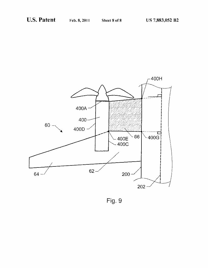
FIG. 9 is a top schematic view of a wing illustrating therange of positions for the leading edge of the wing's inboardsection for an open rotor engine nacelle in accordance withthe present invention;
DETAILED DESCRIPTION OF THE INVENTION
Referring now to the drawings, in which like referencenumbers represent corresponding parts throughout, and moreparticularly to FIG. 2, a top view is shown of a wing 10 inaccordance with an embodiment of the present invention.Wing 10 supports an over-the-wing mounting of a turbofanengine nacelle 100 in a "slipper" (no pylon) fashion. Forexample, as illustrated in the front view of wing 10 in FIG. 3,engine nacelle 100 is attached/integrated into wing 10 with itsintake or highlight 100A being represented by the solid-linecircle and its D-shaped exhaust opening (formed above wing10) represented by dashed lines 100B. Engine nacelle 100 islocated on the forward portion of wing 10, with the exhaustexit 100B generally located at approximately mid-chord tomaximize the noise shielding effect. However, it is to beunderstood that engine nacelle 100 could assume other ver-tical positions relative to wing 10 that still qualify as anover-the-wing mounting without departing from the scope ofthe present invention. The particular methods of attachingand/or integrating engine nacelle 100 with wing 10 via a"slipper" attachment would be understood in the art and arenot limitations of the present invention.
In terms of the present invention, wing 10 has an inboardsection 12 and an outboard section 14, Inboard section 12 isattached to and extends from a plane's fuselage 200 wheresuch attachment is well understood in the art. Inboard section12 extends from fuselage 200 to an inboard side 1000 ofengine nacelle 100 that faces fuselage 200. Outboard section14 extends outward from an outboard side 100D of enginenacelle 100. More specifically, outboard section 14 defines aconventional transonic wing shape that has a substantiallytrapezoidal planform and that has a leading edge 14A with aleading edge sweep of 20 degrees or more. The sweep angleA is measured relative to a line perpendicular to the longitu-dinal axis 202 of fuselage 200 as is known in the art.
In the illustrated embodiment, inboard section 12 has aleading edge 12A with a leading edge sweep of approxi-mately 0 degrees. Further, leading edge 12A mates with theinboard side 1000 of engine nacelle 100 at a position onnacelle 100 that is forward of a point 100E on inboard side1000 of engine nacelle 100. Point 100E is defined as thelocation on inboard side 1000 where the leading edge sweep(represented by dashed lines 14S) of leading edge 14 inter-sects inboard side 1000. In the illustrated embodiment, lead-ing edge 12A mates with inboard side 1000 at a position thatis approximately located at the nacelle's lip region 100F.
The sweep of trailing edges 12B and 14B of inboard sec-tion 12 and outboard section 14, respectively, can be designedon a case-by-case basis and are not part of the present inven-tion. For example, the sweeps of trailing edges 12B and 14Bcan be the same or different without departing from the scopeof the present invention. Further, the sweep of trailing edge12B could be approximately 0 degrees just like leading edge12A.
The present invention is not limited to inboard section wingsweeps of approximately 0 degrees. For example, as illus-trated in FIG. 4, a wing 20 has an inboard section 22 with aleading edge 22A that has a sweep of approximately 15degrees while leading edge 24A of outboard section 24 has asweep of at least 20 degrees. Further, leading edge 22Aattaches to inboard side 1000 at a position on engine nacelle
4100 that is just aft of the highlight 100A of engine nacelle 100.Once again, the configuration of trailing edges 22B and 24Bis not a limitation of the present invention.
The requirements of the present invention can be general-s ized and will be described with the aid of FIG. 5 where a wing
30 has an inboard section 32 and an outboard section 34.Outboard section 34 is a conventional transonic design that isanalogous to outboard section 14 (FIG. 1). A leading edge ofinboard section 32 must have a sweep of —15 to +15 degrees
to and lie anywhere in a hatched region 36 of inboard section 32.Note that hatchedregion 36 is forward of (previously defined)point 100E on inboard side 1000 of engine nacelle 100 andends on engine nacelle 100 just aft of its highlight 10A.Additionally, the hatched region extends from point 100G to
15 point 100H on the fuselage 200.The advantages of the present invention are numerous. The
sweep angle and location of the wing's inboard section rela-tive to an over-the-wing mounted engine nacelle locates andconfines a shock over the leading edge of the wing. This
20 enhances the leading edge suction of the affected wing areawhile reducing the severity of the shock located near thetrailing edge of the wing. The net effect is to reduce overallcompressibility-based interference drag. Wetted area reduc-
25 tion results in a lower friction drag.
Placing the engine exhaust nozzle above the wing shieldsthe lower hemisphere from that noise source, thereby reduc-ing the noise experienced by communities on the ground.That is, engine nozzle exit is tangential to the wing's upper
30 surface and is generally near the middle of the wing localchord to put the exhaust noise source in the best position forthe wing shielding effect. Further, by integrating the enginenacelle into the wing thereby reducing nacelle wetted areaand eliminating the engine mounting pylon altogether, wetted
35 area is used more efficiently to reduce drag. This allows anozzle location above the wing that is at least as missioncapable and cost effective as the conventional installation,which then enables a community noise reduction through theabove-described shielding effect.
40 Elimination of the historically unacceptable interferencedrag of over-the-wing nacelle installation enables many ben-efits to be realized (e.g., flexible installation of high-bypassengines, excellent engine clearance under emergency situa-tions such as collapsed landing gear or water ditching,
45 reduced "foreign object damage" susceptibility, reducedground damage from servicing accidents, increased torsionalstiffness thereby increasing flutter margin, reduced commu-nity noise through wing shielding, possible gapless flaps tolower airframe noise and increase lift, flexible landing gear
50 design and placement to save weight and reduce airframenoise).
In an alternate embodiment of the present invention, anopen rotor (also commonly referred to in the past as unductedfan (UDF) or prop fan) is mounted in the over-the-wing
55 configuration in a "slipper" (no pylon) fashion. Referringnow to FIG. 6, wing 40 supports an over-the-wing mountingof an open rotor engine nacelle 400 having a spinner base400A. As illustrated in the front view of wing 40 in FIG. 7,engine nacelle 400 is attached/integrated onto wing 40.
6o Engine nacelle 400 is located on the forward portion of wing40, with the exhaust exit 400B generally located at approxi-mately mid-chord to maximize the noise shielding effect. It isto be understood that engine nacelle 400 could assume othervertical positions relative to wing 40 that still qualify as an
65 over-the-wing mounting without departing from the scope ofthe present invention. The particular methods of attachingand/or integrating engine nacelle 400 with wing 40 via a

US 7,883,052 B25
"slipper" attachment would be understood in the art and arenot limitations of the present invention.
Inboard section 42 of wing 40 is attached to and extendsfrom a plane's fuselage 200 where such attachment is wellunderstood in the art. Inboard section 42 extends from fuse-lage 200 to an inboard side 4000 of engine nacelle 400 thatfaces fuselage 200. Outboard section 44 extends outwardfrom an outboard side 400D of engine nacelle 400. Morespecifically, outboard section 44 defines a conventional tran-sonic wing shape that has a substantially trapezoidal plan-form and that has a leading edge 44A with a leading edgesweep of 20 degrees or more. The sweep angleA is measuredrelative to a line perpendicular to the longitudinal axis 202 offuselage 200 as is known in the art.
Inboard section 42 has a leading edge 42A with a leadingedge sweep of approximately 0 degrees. Further, leading edge42A mates with the inboard side 4000 of engine nacelle 400at a position on nacelle 400 that is forward of a point 400E oninboard side 4000 of engine nacelle 400. Point 400E isdefined as the location on inboard side 4000 where the lead-ing edge sweep (represented by dashed lines 44S) of leadingedge 44 intersects inboard side 4000. In the illustratedembodiment, leading edge 42A mates with inboard side 4000at a position that is located approximately midway betweenthe spinner base 400A and point 400E.
The sweep of trailing edges 42B and 44B of inboard sec-tion 42 and outboard section 44, respectively, can be designedon a case-by-case basis and are not part of the present inven-tion. For example, the sweeps of trailing edges 42B and 44Bcan be the same or different without departing from the scopeof the present invention. Further, the sweep of trailing edge42B could be approximately 0 degrees just like leading edge42A.
This embodiment is not limited to inboard section wingsweeps of approximately 0 degrees. For example, as illus-trated in FIG. 8, a wing 50 has an inboard section 52 with aleading edge 52A that has a sweep of 15 degrees while lead-ing edge 54A of outboard section 24 has a sweep of at least 20degrees. Further, leading edge 52A attaches to inboard side4000 at a position on engine nacelle 400 that is approximatelyat the spinner base 400A of engine nacelle 400. Once again,the configuration of trailing edges 52B and 54B is not alimitation of the present invention.
The requirements of this embodiment can be generalizedand will be described with the aid of FIG. 9 where a wing 60has an inboard section 62 and an outboard section 64. Out-board section 64 is a conventional transonic design that isanalogous to outboard section 14 (FIG. 1). A leading edge ofinboard section 62 must have a sweep of —15 to +15 degreesand lie anywhere in a hatched region 66 of inboard section 62.Note that hatched region 66 is forward of (previously defined)point 400E on inboard side 4000 of engine nacelle 400 andends on engine nacelle 400 at approximately the spinner base400A. Additionally, the hatched region extends from point400G to point 400H on the fuselage 200.
Although the invention has been described relative to spe-cific embodiments thereof, there are numerous variations andmodifications that will be readily apparent to those skilled inthe art in light of the above teachings. For example, while thepresent invention is particularly applicable to wings mountedlow on the fuselage, it would also be applicable to wingsmounted mid or high on the fuselage. It is therefore to beunderstood that, within the scope of the appended claims, theinvention may be practiced other than as specificallydescribed.
6What is claimed as new and desired to be secured by
Letters Patent of the United States is:1. A wing, comprising:an inboard section adapted to be attached on one side
5 thereof to a fuselage and adapted to be attached on anopposing side thereof to an inboard side of an enginenacelle in an over-the-wing mounting position, saidinboard section having a leading edge and a trailingedge;
10 an outboard section adapted to be attached on one sidethereof to an outboard side of said nacelle, said outboardsection having a leading edge and a trailing edge;
said outboard section leading edge having a sweep of atleast 20 degrees;
15 said inboard section leading edge having a sweep between—15 and +15 degrees; and
said inboard section leading edge extending from saidfuselage to an attachment position on said nacelle,wherein the attachment position on said fuselage and
20 said attachment position on said nacelle are forward ofan index position on the inboard side of said nacelle, saidindex position defined as an imaginary intersectionbetween said sweep of said outboard section and saidinboard side of said nacelle.
25 2. A wing as in claim 1 wherein said sweep of said inboardsection leading edge is 0 degrees.
3. A wing as in claim 1 wherein said nacelle is a turbofanengine nacelle and said nacelle attachment position is aft of ahighlight of said nacelle.
so 4. A wing as in claim 1 wherein said nacelle is an open rotorengine nacelle and said nacelle attachment position is aft of aspinner base of said nacelle.
5. A wing as in claim 1 wherein said nacelle is a turbofan35 engine nacelle and said nacelle attachment position is
approximately at an intake lip of said nacelle.6.A wing as in claim 1 wherein said nacelle is an open rotor
engine nacelle and said nacelle attachment position isapproximately midway between a spinner base of said nacelle
40 and said index position.7. A wing as in claim 1 wherein said nacelle is a turbofan
engine nacelle, said sweep of said inboard section leadingedge is 0 degrees and said nacelle attachment position is aft ahighlight of said nacelle.
45 8. A wing as in claim 1 wherein said nacelle is an open rotorengine nacelle, said sweep of said inboard section leadingedge is 0 degrees and said nacelle attachment position is aft ofa spinner base of said nacelle.
9. A wing as in claim 1 wherein said nacelle is a turbofan
50 engine nacelle, said sweep of said inboard section leadingedge is 0 degrees and said nacelle attachment position isapproximately at an intake lip of said nacelle.
10. A wing as in claim 1 wherein said nacelle is an openrotor engine nacelle, said sweep of said inboard section lead-
55 ing edge is 0 degrees and said nacelle attachment position isapproximately midway between a spinner base of said nacelleand said index position.
11. A wing, comprising:an inboard section adapted to be attached on one side
60 thereof to a fuselage and adapted to be attached on anopposing side thereof to an inboard side of a turbofanengine nacelle in an over-the-wing mounting position,said inboard section having a leading edge and a trailingedge;
65 an outboard section adapted to be attached on one sidethereof to an outboard side of said nacelle, said outboardsection having a leading edge and a trailing edge;

US 7,883,052 B27
said outboard section leading edge having a sweep of atleast 20 degrees;
said inboard section leading edge having a sweep ofapproximately 0 degrees; and
said inboard section leading edge extending from saidfuselage to an attachment position on said nacelle that is(i) forward of an index position on the inboard side ofsaid nacelle, said index position defined as an imaginaryintersection between said sweep of said outboard sectionand said inboard side of said nacelle, and (ii) aft of ahighlight of said nacelle, and further wherein the attach-ment position on said fuselage is forward of said indexposition.
12. A wing as in claim 7 wherein said nacelle attachmentposition is approximately at an intake lip of said nacelle.
13. A wing, comprising:an inboard section adapted to be attached on one side
thereof to a fuselage and adapted to be attached on anopposing side thereof to an inboard side of an open rotorengine nacelle in an over-the-wing mounting position,said inboard section having a leading edge and a trailingedge;
an outboard section adapted to be attached on one sidethereof to an outboard side of said nacelle, said outboardsection having a leading edge and a trailing edge;
said outboard section leading edge having a sweep of atleast 20 degrees;
said inboard section leading edge having a sweep ofapproximately 0 degrees; and
said inboard section leading edge extending from saidfuselage to an attachment position on said nacelle that is(i) forward of an index position on said inboard side ofsaid nacelle, said index position defined as an imaginaryintersection between said sweep of said outboard sectionand said inboard side of said nacelle, and (ii) aft of aspinner base of said nacelle, and further wherein theattachment position on said fuselage is forward of saidindex position.
14.A wing as in claim 13 wherein said nacelle attachmentposition is approximately midway between said spinner baseand said index position.
15. A wing, comprising:an inboard section adapted to be attached on one side
thereof to a fuselage and adapted to be attached on anopposing side thereof to an inboard side of an enginenacelle in an over-the-wing mounting position, saidinboard section having a leading edge and a trailingedge;
a substantially trapezoidal outboard section adapted to beattached on one side thereof to an outboard side of said
8nacelle wherein said nacelle is integrated into saidinboard section and said outboard section in the over-the-wing mounting position, said outboard section hav-ing a leading edge and a trailing edge;
5 said outboard section leading edge having a sweep of atleast 20 degrees;
said outboard section trailing edge joining to said inboardsection trailing edge aft of said nacelle;
said inboard section leading edge having a sweep between10 —15 and +15 degrees; and
said inboard section leading edge extending from saidfuselage to an attachment position on said nacelle that isforward of an index position on the inboard side of saidnacelle, said index position defined as an imaginary
15 intersection between said sweep of said outboard sectionand said inboard side of said nacelle, further wherein theattachment position on said fuselage is forward of saidindex position.
16. A wing as in claim 15 wherein said sweep of said20 inboard section leading edge is 0 degrees.
17.A wing as in claim 15 wherein said nacelle is a turbofanengine nacelle and said nacelle attachment position is aft of ahighlight of said nacelle.
18. A wing as in claim 15 wherein said nacelle is an open25 rotor engine nacelle and said nacelle attachment position is
aft of a spinner base of said nacelle.19.A wing as in claim 15 wherein said nacelle is a turbofan
engine nacelle and said nacelle attachment position isapproximately at an intake lip of said nacelle.
30 20. A wing as in claim 15 wherein said nacelle is an openrotor engine nacelle and said nacelle attachment position isapproximately midway between a spinner base of said nacelleand said index position.
21. A wing as in claim 15 wherein said nacelle is a turbofan35 engine nacelle, said sweep of said inboard section leading
edge is 0 degrees and said nacelle attachment position is aft ofa highlight of said nacelle.
22. A wing as in claim 15 wherein said nacelle is an openrotor engine nacelle, said sweep of said inboard section lead-
40 ing edge is 0 degrees and said nacelle attachment position isaft of a spinner base of said nacelle.
23. A wing as in claim 15 wherein said nacelle is a turbofanengine nacelle, said sweep of said inboard section leadingedge is 0 degrees and said nacelle attachment position is
45 approximately at an intake lip of said nacelle.24. A wing as in claim 15 wherein said nacelle is an open
rotor engine nacelle, said sweep of said inboard section lead-ing edge is 0 degrees and said nacelle attachment position isapproximately at an intake lip of said nacelle.