multi air conditioning system for buildings airstage v-2.pdf · large capacity multi vrf system dc...
TRANSCRIPT
Large Capacity Multi VRF SystemDC Inverter Control Compressor Long Piping System Design High Efficiency Refrigerant R410A
Multi Air Conditioning System for Buildings
N807
All products specified in this brochure comply with the AustralianCommunications Authority's (ACA)requirements for Electromagnetic
The colors may be different from the actual colors because this catalog is printed matter.Product specifications are subject to change without notice.
Distributed by :
“ ” is a worldwide trademark of FUJITSU GENERAL LIMITED and is a registered trademark in Japan, the U.S.A and other countries or areas.*Microsoft® and Windows® are registered trademarks of Microsoft Corporation in the United States.*Adobe® Reader® are registered trademarks of Adobe Systems Incorporated in the United States.*Intel®, Pentium® and Celeron® are registered trademark of Intel Corporation or its subsidiaries in the United States.*AMD AthlonTM and AMD DuronTM are registered trademark of Advanced Micro Devices, Inc.*Echelon®, LONWORKS®, and the Echelon logo are trademarks of Echelon Corporation registered in the United States and other countries.*BACnet® is a registered trademark of the American Society of Heating Refrigeration and Air Conditioning Engineers (ASHRAE).
6NNV25-1010E
1116, Suenaga, Takatsu-ku, Kawasaki 213-8502, Japanhttp://www.fujitsu-general.com/
Copyright© 2009-2010 Fujitsu General Limited. All rights reserved.
Fujitsu General (Thailand) Co., Ltd.
ISO 9001Certified number : 01 100 89394
ISO 14001Certified number : 01 104 9245101
Fujitsu General (Shanghai) Co., Ltd.
ISO 9001Certified number : 01 100 79269
ISO 14001Certified number : 272043
Fujitsu General Central Air-conditioner (Wuxi) Co., Ltd.
ISO 9001Certified number : 00608Q11061R2M
ISO 14001Certified number : 00609E20454R2M
Jäähdytinpalvelu RefGroup Oy, Kelatie 9 C, 01450 Vantaa, puh. 050 - 433 2222, fax 09 - 242 4277, [email protected], www.ilmalampopumput.com
FEATURESHigh Efficiency Operation ................. 4Design Versatility .............................. 6High Reliability .................................. 8Easy Installation .............................. 10Comfort and Convenience .............. 12Easy Service & Maintenance ......... 14
OUTDOOR UNITSLineup ............................................. 16Specifications ................................. 18Dimensions ..................................... 20
INDOOR UNITSLineup.............................................. 22Compact Cassette .......................... 24Cassette ......................................... 26Compact Duct ................................. 28Slim Duct ....................................... 30Low Static Pressure Duct / Duct...... 32High Static Pressure Duct .............. 34Floor / Ceiling ................................. 36Ceiling ............................................. 38Compact Wall Mounted .................. 40Wall Mounted .................................. 42
CONTROLLERControl System ............................... 44Wiring System ................................. 46Comparison table of Controllers ...... 47Wired Remote Controller ................. 48Simple Remote Controller ............... 49Wireless Remote Controller ............ 50IR Receiver Unit ............................. 51IR Receiver Kit ............................... 51Group Remote Controller ............... 52Central Remote Controller............... 54Touch Panel Controller ................... 56System Controller (Software) ............. 58
CONVERTOR & ADAPTORNetwork Convertor ......................... 62Network Convertor for LONWORKS® ..... 63BACnet® Gateway (Software) ............ 64Signal Amplifier .............................. 65External Switch Controller .............. 65
SERVICE & MONITORINGService Tool (Software) ...................... 66Web Monitoring Tool (Software) ......... 68
OTHERSEnergy Recovery Ventilator ............ 70Fujitsu General Supports Diverse
VRF System Design ....................... 72Optional Parts ................................. 73
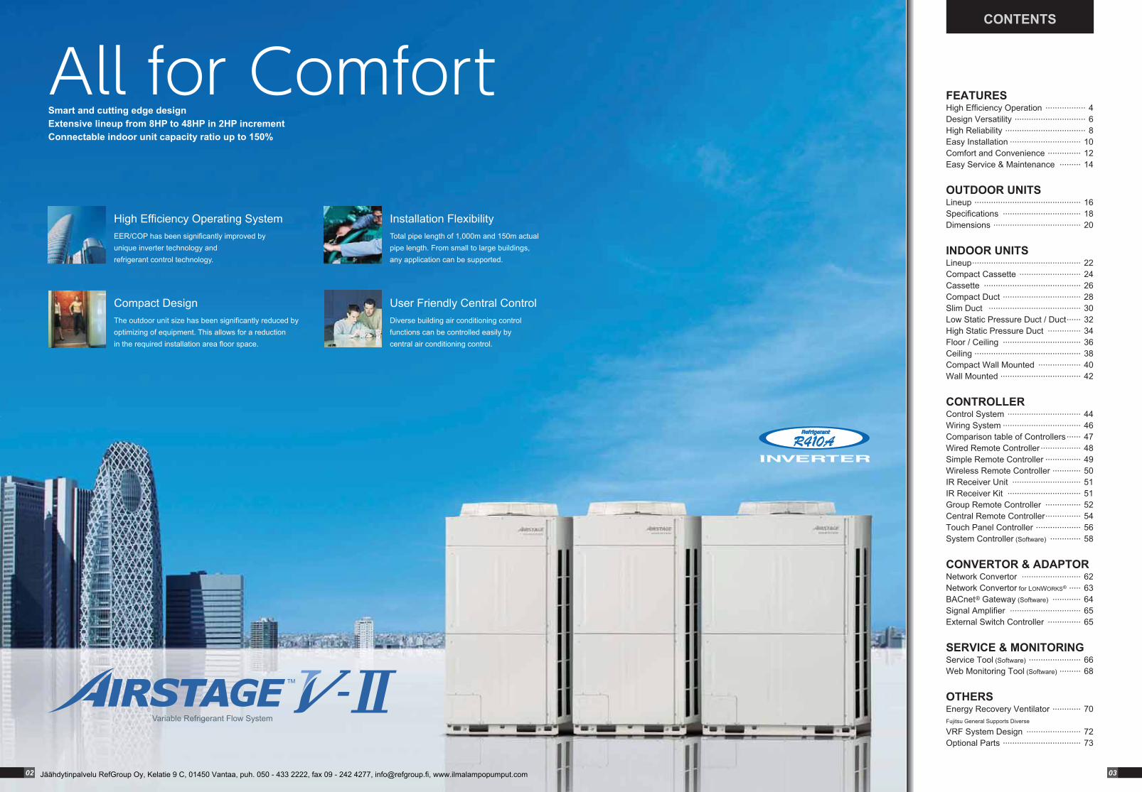
High Efficiency Operating SystemEER/COP has been significantly improved by unique inverter technology and refrigerant control technology.
Smart and cutting edge designExtensive lineup from 8HP to 48HP in 2HP incrementConnectable indoor unit capacity ratio up to 150%
All for Comfort
Installation FlexibilityTotal pipe length of 1,000m and 150m actual pipe length. From small to large buildings, any application can be supported.
Compact DesignThe outdoor unit size has been significantly reduced by optimizing of equipment. This allows for a reduction in the required installation area floor space.
User Friendly Central ControlDiverse building air conditioning control functions can be controlled easily by central air conditioning control.
CONTENTS
02 03Jäähdytinpalvelu RefGroup Oy, Kelatie 9 C, 01450 Vantaa, puh. 050 - 433 2222, fax 09 - 242 4277, [email protected], www.ilmalampopumput.com
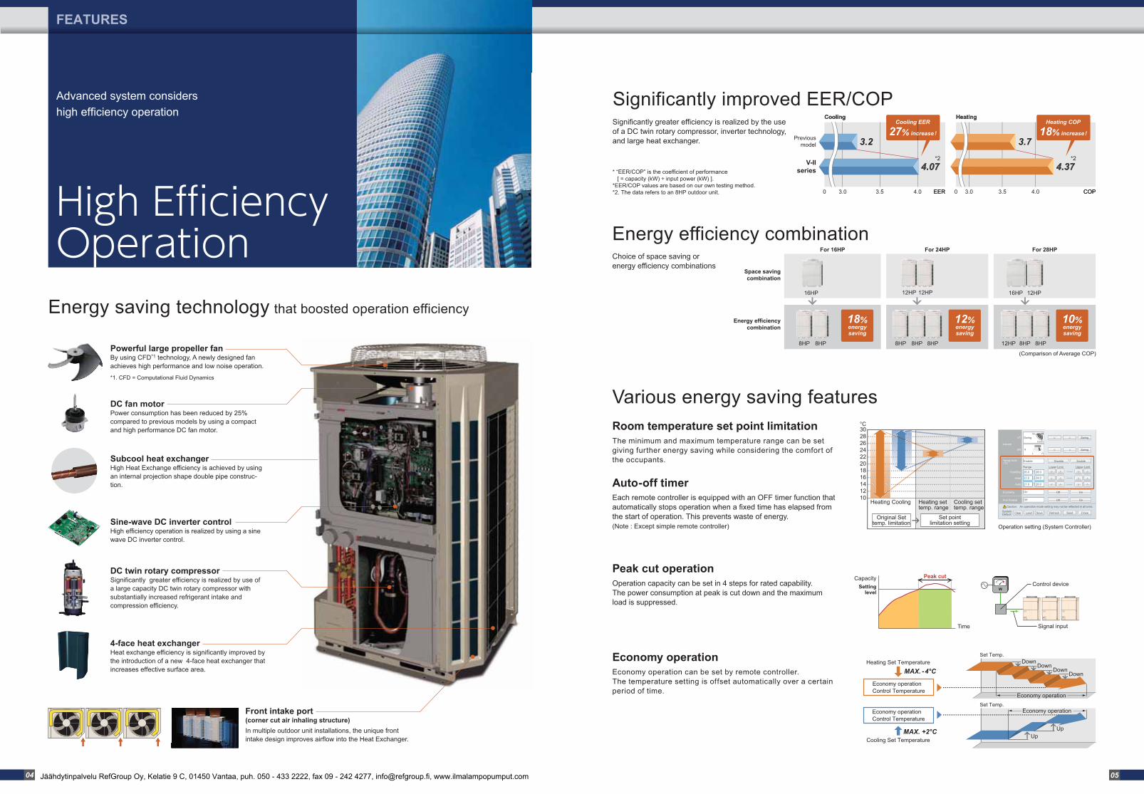
4-face heat exchanger Heat exchange efficiency is significantly improved by the introduction of a new 4-face heat exchanger that increases effective surface area.
Front intake port (corner cut air inhaling structure)In multiple outdoor unit installations, the unique front intake design improves airflow into the Heat Exchanger.
Energy saving technology that boosted operation efficiency
Significantly improved EER/COP Significantly greater efficiency is realized by the use of a DC twin rotary compressor, inverter technology, and large heat exchanger.
DC fan motor Power consumption has been reduced by 25% compared to previous models by using a compact and high performance DC fan motor.
Previousmodel
V-IIseries
3.0 3.50 4.0 COPCOPEEREER3.0 3.50 4.0
CoolingCooling HeatingHeating
3.2 3.7
4.074.07 4.374.37* “EER/COP” is the coefficient of performance [ = capacity (kW) ÷ input power (kW) ].*EER/COP values are based on our own testing method.*2. The data refers to an 8HP outdoor unit.
Sine-wave DC inverter controlHigh efficiency operation is realized by using a sine wave DC inverter control.
Subcool heat exchangerHigh Heat Exchange efficiency is achieved by using an internal projection shape double pipe construc-tion.
DC twin rotary compressorSignificantly greater efficiency is realized by use of a large capacity DC twin rotary compressor with substantially increased refrigerant intake and compression efficiency.
For 16HP
Space savingcombination
Energy efficiencycombination
18%energysaving
16HP
8HP 8HP
For 24HP
12%energysaving
For 28HP
8HP 8HP 8HP 12HP 8HP 8HP
16HP 12HP
(Comparison of Average COP)
*2 *2
Economy operationEconomy operation can be set by remote controller.The temperature setting is offset automatically over a certain period of time.
Room temperature set point limitationThe minimum and maximum temperature range can be set giving further energy saving while considering the comfort of the occupants.
Peak cut operationOperation capacity can be set in 4 steps for rated capability. The power consumption at peak is cut down and the maximum load is suppressed.
Auto-off timerEach remote controller is equipped with an OFF timer function that automatically stops operation when a fixed time has elapsed from the start of operation. This prevents waste of energy. (Note : Except simple remote controller)
Cooling Set Temperature
Economy operationControl Temperature
Heating Set Temperature
Economy operationControl Temperature
Set Temp.
MAX. -4°C
MAX. +2°C
Economy operation
UpUp
Economy operation
Set Temp.Down
DownDown
Down
Heating set temp. range
Cooling set temp. range
Heating Cooling
Original Settemp. limitation
Set pointlimitation setting
°C3028262422201816141210
Operation setting (System Controller)
W
Capacity
Time
Settinglevel
Peak cutControl device
Signal input
High Efficiency Operation
FEATURES
Advanced system considers high efficiency operation
Energy efficiency combination
Various energy saving features
Choice of space saving or energy efficiency combinations
Powerful large propeller fanBy using CFD*1 technology, A newly designed fan achieves high performance and low noise operation.
12HP 12HP
10%energysaving
*1. CFD = Computational Fluid Dynamics
Cooling EER
27% increase !
Heating COP
18% increase !
04 05Jäähdytinpalvelu RefGroup Oy, Kelatie 9 C, 01450 Vantaa, puh. 050 - 433 2222, fax 09 - 242 4277, [email protected], www.ilmalampopumput.com
15m max.
Height difference between indoor and indoor units
60m max.
Pipe length from first separation tube to the farthest indoor unit
Actual pipe length
150m max.
1,000m max.
Total pipe length
50m max.For the outdoor unit stated below : 40m max.
Height difference between outdoor and indoor units
*1. Note : When there is 1 outdoor unit, the maximum is 700m.
*1
FEATURES
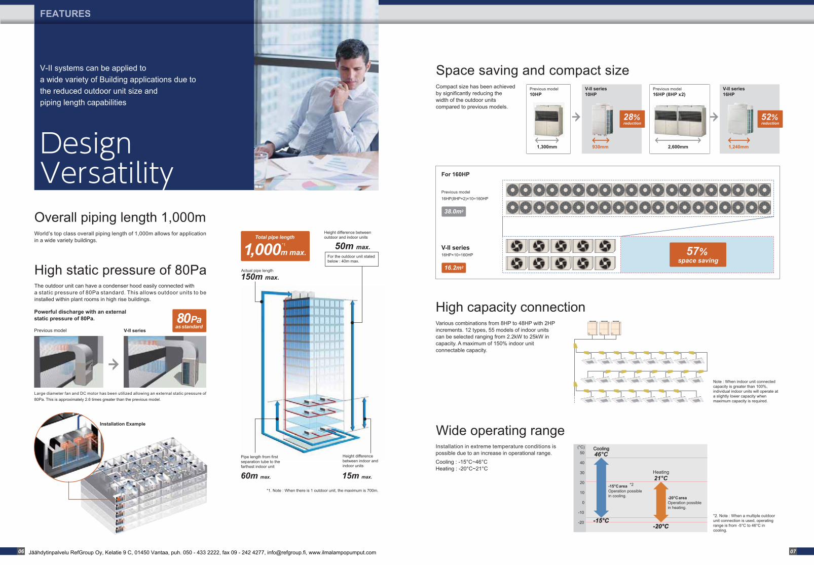
V-II systems can be applied to a wide variety of Building applications due to the reduced outdoor unit size and piping length capabilities
High static pressure of 80Pa
Overall piping length 1,000mWorld’s top class overall piping length of 1,000m allows for application in a wide variety buildings.
The outdoor unit can have a condenser hood easily connected with a static pressure of 80Pa standard. This allows outdoor units to be installed within plant rooms in high rise buildings.
Space saving and compact sizeCompact size has been achieved by significantly reducing the width of the outdoor units compared to previous models.
Design Versatility
Large diameter fan and DC motor has been utilized allowing an external static pressure of 80Pa. This is approximately 2.6 times greater than the previous model.
Installation Example
80Paas standard
Installation in extreme temperature conditions is possible due to an increase in operational range.Cooling : -15°C~46°CHeating : -20°C~21°C
Wide operating range
Various combinations from 8HP to 48HP with 2HP increments. 12 types, 55 models of indoor units can be selected ranging from 2.2kW to 25kW in capacity. A maximum of 150% indoor unit connectable capacity.
High capacity connection
Previous model10HP
V-II series10HP
52% reduction
28% reduction
CoolingCooling46°C
21°C
-15°C -15°C -20°C -20°C
Heating
(°C)
-15°C areaOperation possiblein cooling. -20°C area
Operation possiblein heating.
50
40
30
20
10
0
-10
-20
*2
*2. Note : When a multiple outdoor unit connection is used, operating range is from -5°C to 46°C in cooling.
Note : When indoor unit connected capacity is greater than 100%, individual indoor units will operate at a slightly lower capacity when maximum capacity is required.
For 160HP
Previous model V-II series
Powerful discharge with an external static pressure of 80Pa.
16HP(8HP×2)×10=160HP
38.0m2
Previous model
16HP×10=160HP
16.2m2
V-II series 57% space saving
1,300mm 930mm
Previous model16HP (8HP x2)
V-II series16HP
2,600mm 1,240mm
06 07Jäähdytinpalvelu RefGroup Oy, Kelatie 9 C, 01450 Vantaa, puh. 050 - 433 2222, fax 09 - 242 4277, [email protected], www.ilmalampopumput.com
Transmission line
USB adaptor (Field supplied)
Outdoor unit
Web Monitoring ToolInternetor
Public Telephone Line
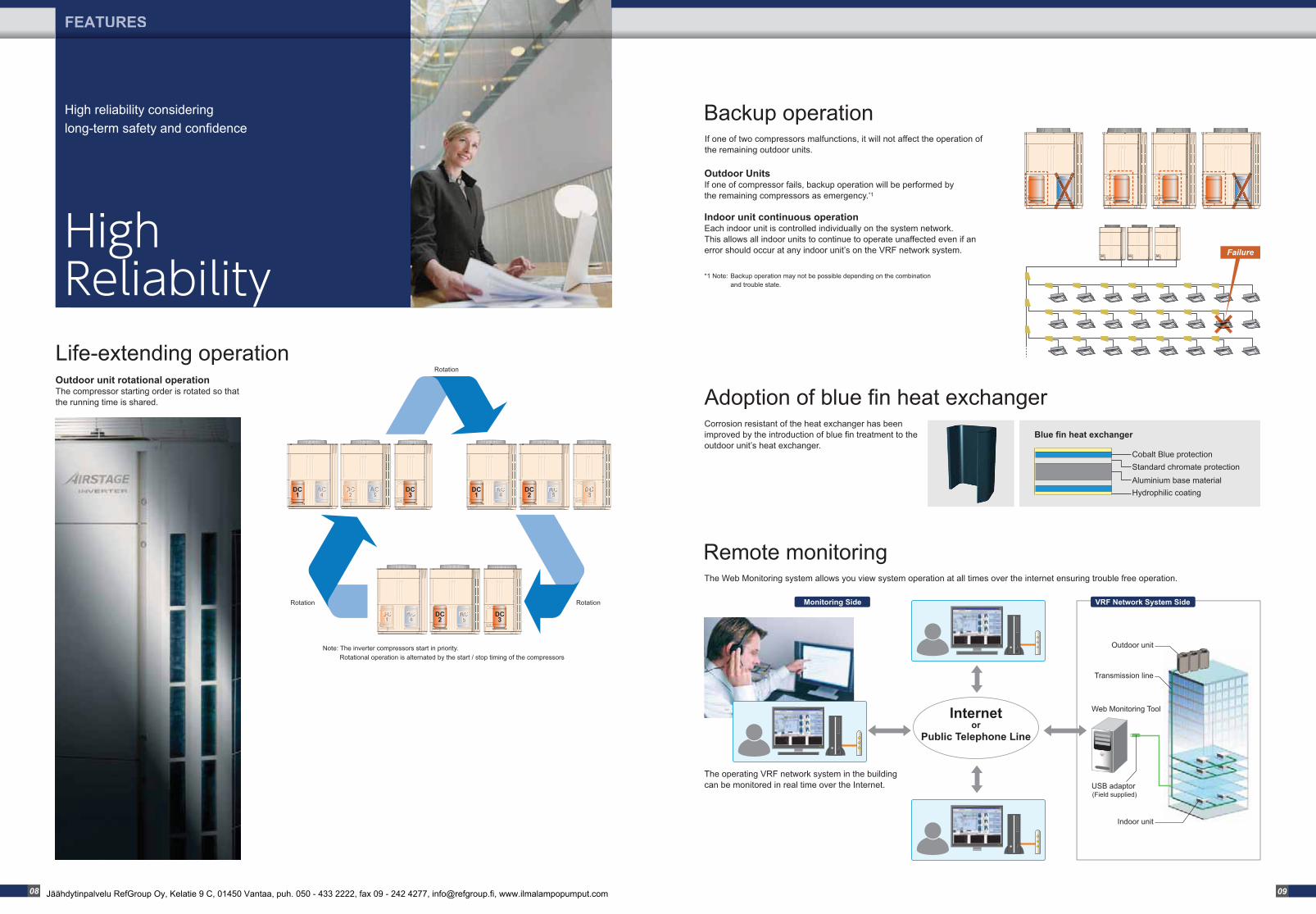
Backup operation may not be possible depending on the combination and trouble state.
*1 Note:
Monitoring Side VRF Network System Side
The operating VRF network system in the building can be monitored in real time over the Internet.
High Reliability
FEATURES
High reliability considering long-term safety and confidence
Note: The inverter compressors start in priority. Rotational operation is alternated by the start / stop timing of the compressors
Failure
Corrosion resistant of the heat exchanger has been improved by the introduction of blue fin treatment to the outdoor unit’s heat exchanger.
Outdoor UnitsIf one of compressor fails, backup operation will be performed by the remaining compressors as emergency.*1
Indoor unit continuous operationEach indoor unit is controlled individually on the system network. This allows all indoor units to continue to operate unaffected even if an error should occur at any indoor unit’s on the VRF network system.
Backup operationIf one of two compressors malfunctions, it will not affect the operation of the remaining outdoor units.
The Web Monitoring system allows you view system operation at all times over the internet ensuring trouble free operation.
Remote monitoring
Adoption of blue fin heat exchanger
Hydrophilic coating
Cobalt Blue protectionStandard chromate protectionAluminium base material
Blue fin heat exchanger
DC2
DC3
DC1
DC3
DC1
DC2
Rotation
Rotation Rotation
Life-extending operationOutdoor unit rotational operationThe compressor starting order is rotated so that the running time is shared.
Indoor unit
08 09Jäähdytinpalvelu RefGroup Oy, Kelatie 9 C, 01450 Vantaa, puh. 050 - 433 2222, fax 09 - 242 4277, [email protected], www.ilmalampopumput.com
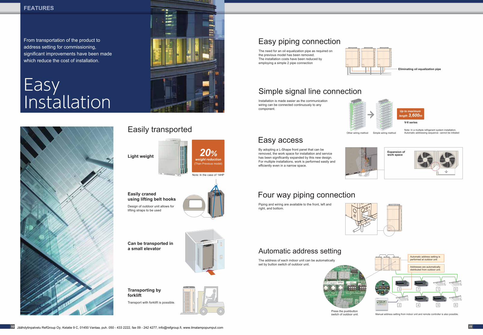
Transport with forklift is possible.
Easy Installation
FEATURES
From transportation of the product to address setting for commissioning, significant improvements have been made which reduce the cost of installation.
Simple wiring methodOther wiring method
Design of outdoor unit allows for lifting straps to be used
Up to maximum length 3,600m
Installation is made easier as the communication wiring can be connected continuously to any component.
Simple signal line connection
20%weight reduction
(Than Previous model)
Note: In the case of 14HP
Light weight
Easily craned using lifting belt hooks
Transporting by forklift
Can be transported in a small elevator
V-II series
Note: In a multiple refrigerant system installation, Automatic addressing sequence cannot be initiated
The address of each indoor unit can be automatically set by button switch of outdoor unit.
Automatic address setting
Four way piping connectionPiping and wiring are available to the front, left and right, and bottom.
Easy accessExpansion of work space
By adopting a L-Shape front panel that can be removed, the work space for installation and service has been significantly expanded by this new design. For multiple installations, work is performed easily and efficiently even in a narrow space.
Automatic address setting is performed at outdoor unit
Addresses are automaticallydistributed from outdoor unit.
Manual address setting from indoor unit and remote controller is also possible.
7 1 0
2 4 5 6
Press the pushbutton switch of outdoor unit.
Eliminating oil equalization pipe
Easily transported
Easy piping connectionThe need for an oil equalization pipe as required on the previous model has been removed. The installation costs have been reduced by employing a simple 2 pipe connection
3
10 11Jäähdytinpalvelu RefGroup Oy, Kelatie 9 C, 01450 Vantaa, puh. 050 - 433 2222, fax 09 - 242 4277, [email protected], www.ilmalampopumput.com
Room A24°C
Room C27°C
Room DOFF
Room E23°C
Room B18°C
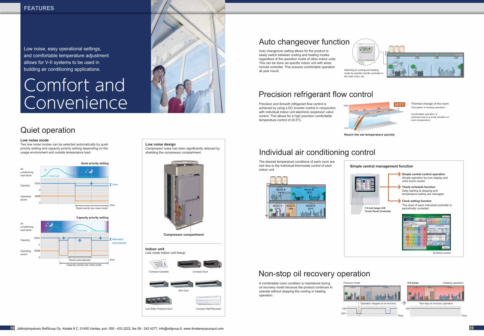
Precision refrigerant flow control
Simple central management function
Individual air conditioning control
Simple central control operation
Yearly schedule function
Simple operation by icon display and color touch screen
Clock setting function
7.5 inch large LCD Touch Panel Controller
Schedule screen
Daily starting & stopping and temperature setting are managed.
The clock of each individual controller is periodically corrected.
Thermal change of the room*Simulation in heating operation.
Comfortable operation is achieved due to a small variation of room temperature
Comfort and Convenience
FEATURES
Low noise, easy operational settings, and comfortable temperature adjustment allows for V-II systems to be used in building air conditioning applications.
Compressor compartment
Low noise design Compressor noise has been significantly reduced by shielding the compressor compartment.
Indoor unit Low noise indoor unit lineup
Auto changeover setting allows for the product to easily switch between cooling and heating modes regardless of the operation mode of other indoor units. This can be done via specific indoor unit with wired remote controller. This ensures comfortable operation all year round. Switching to cooling and heating
mode by specific remote controller in the main room, etc.
Auto changeover function
Compact Duct
Slim Duct
Low Static Pressure Duct Compact Wall Mounted
Compact Cassette
Air conditioning load factor
Capacity
Operating sound
Air conditioning load factor
Capacity
Operating sound
time
100%
58dB
0
0
Heat load
down
Quiet priority low noise mode
Quiet priority setting
Capacity priority low noise mode
time
100%
58dB
0
0Reset automatically
Alternatedautomatically
Capacity priority setting
Heat loadHeat loadHeat load
Low noise modeTwo low noise modes can be selected automatically by quiet priority setting and capacity priority setting depending on the usage environment and outside temperature load.
Precision and Smooth refrigerant flow control is achieved by using a DC Inverter control in conjunction with individual indoor unit electronic expansion valve control. This allows for a high precision comfortable temperature control of ±0.5°C.
The desired temperature conditions of each room are met due to the Individual thermostat control of each indoor unit.
Reach the set temperature quickly
Low
High
Set temp.
ColdCold
Hot Hot±0.5�C
A comfortable room condition is maintained during oil recovery mode because the product continues to operate without stopping the cooling or heating operation.
Non-stop oil recovery operationPrevious model V-II series (Heating operation)
Time
ON
OFF
Operation stopped at oil recovery
Time
ON
Non-stop oil recovery operation
Quiet operation
12 13Jäähdytinpalvelu RefGroup Oy, Kelatie 9 C, 01450 Vantaa, puh. 050 - 433 2222, fax 09 - 242 4277, [email protected], www.ilmalampopumput.com
SU MO TU WE TH FR SA
Indoor unit
Easy Service & Maintenance
FEATURES
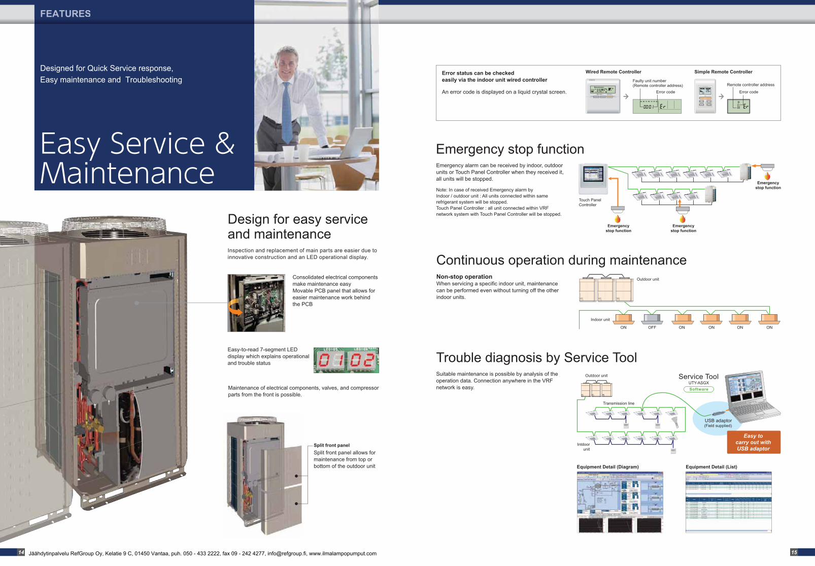
Designed for Quick Service response, Easy maintenance and Troubleshooting
Emergency alarm can be received by indoor, outdoor units or Touch Panel Controller when they received it, all units will be stopped.
Split front panel allows for maintenance from top or bottom of the outdoor unit
Maintenance of electrical components, valves, and compressor parts from the front is possible.
Easy-to-read 7-segment LED display which explains operational and trouble status
Note: In case of received Emergency alarm by Indoor / outdoor unit : All units connected within same refrigerant system will be stopped. Touch Panel Controller : all unit connected within VRF network system with Touch Panel Controller will be stopped.
Non-stop operationWhen servicing a specific indoor unit, maintenance can be performed even without turning off the other indoor units.
Emergency stop function
Suitable maintenance is possible by analysis of the operation data. Connection anywhere in the VRF network is easy.
Trouble diagnosis by Service Tool
Continuous operation during maintenance
ON OFF ON ON ON ON
Intdoor unit
USB adaptor(Field supplied)
Service Tool
Transmission line
Outdoor unit
Outdoor unit
Easy tocarry out withUSB adaptor
Touch Panel Controller
Emergencystop function
Emergencystop function
Emergencystop function
SoftwareUTY-ASGX
Inspection and replacement of main parts are easier due to innovative construction and an LED operational display.
Consolidated electrical components make maintenance easyMovable PCB panel that allows for easier maintenance work behind the PCB
Split front panel
Equipment Detail (Diagram) Equipment Detail (List)
Design for easy service and maintenance
Wired Remote Controller Simple Remote ControllerError status can be checked easily via the indoor unit wired controller
An error code is displayed on a liquid crystal screen.
Faulty unit number(Remote controller address)
Error code
Remote controller address
Error code
14 15Jäähdytinpalvelu RefGroup Oy, Kelatie 9 C, 01450 Vantaa, puh. 050 - 433 2222, fax 09 - 242 4277, [email protected], www.ilmalampopumput.com

Energy efficiency combination
Space saving combination
AJ* : AJY(FUJITSU), AJH(GENERAL)
Outdoor Units Lineup
OUTDOOR UNITS
AJ*A72LALHUNIT : AJ*A72LALH
AJ*A90LALHUNIT : AJ*A90LALH
AJ*108LALHUNIT : AJ*108LALH
AJ*126LALHUNIT : AJ*126LALH
AJ*144LALHUNIT : AJ*144LALH
AJ*162LALHUNIT : AJ*A90/A72LALH
AJ*180LALHUNIT : AJ*108/A72LALH
AJ*198LALHUNIT : AJ*108/A90LALH
AJ*216LALHUNIT : AJ*108/108LALH
AJ*234LALHUNIT : AJ*126/108LALH
AJ*252LALHUNIT : AJ*144/108LALH
AJ*270LALHUNIT : AJ*144/126LALH
AJ*288LALHUNIT : AJ*144/144LALH
AJ*306LALHUNIT : AJ*108/108/A90LALH
AJ*324LALHUNIT : AJ*108/108/108LALH
AJ*342LALHUNIT : AJ*126/108/108LALH
AJ*360LALHUNIT : AJ*144/108/108LALH
AJ*378LALHUNIT : AJ*144/126/108LALH
AJ*396LALHUNIT : AJ*144/144/108LALH
AJ*414LALHUNIT : AJ*144/144/126LALH
AJ*432LALHUNIT : AJ*144/144/144LALH
22.4kW (8HP) 33.5kW (12HP)28.0kW (10HP) 40.0kW (14HP) 50.4kW (18HP)45.0kW (16HP)
55.9kW (20HP) 67.0kW (24HP)61.5kW (22HP) 85.0kW (30HP)73.5kW (26HP) 78.5kW (28HP)
AJ*144LALHHUNIT : AJ*A72/A72LALH
AJ*198LALHHUNIT : AJ*126/A72LALH
AJ*216LALHHUNIT : AJ*A72/A72/A72LALH
AJ*234LALHHUNIT : AJ*A90/A72/A72LALH
AJ*252LALHHUNIT : AJ*108/A72/A72LALH
AJ*270LALHHUNIT : AJ*126/A72/A72LALH
AJ*288LALHHUNIT : AJ*108/108/A72LALH
AJ*306LALHHUNIT : AJ*126/108/A72LALH
AJ*324LALHHUNIT : AJ*126/126/A72LALH
AJ*360LALHHUNIT : AJ*126/126/108LALH
AJ*378LALHHUNIT : AJ*126/126/126LALH
AJ*396LALHHUNIT : AJ*144/126/126LALH
44.8kW (16HP) 67.2kW (24HP)62.4kW (22HP) 72.8kW (26HP) 84.8kW (30HP)78.3kW (28HP)
89.8kW (32HP) 102.4kW (36HP)95.9kW (34HP) 125.0kW (44HP)113.5kW (40HP) 120.0kW (42HP)
100.5kW (36HP)90.0kW (32HP) 95.0kW (34HP) 118.5kW (42HP)107.0kW (38HP) 112.0kW (40HP)
135.0kW (48HP)123.5kW (44HP) 130.0kW (46HP)
• Extensive line up from 8HP to 48HP in 2HP increments• Space saving combination and Energy efficiency combination available, which can be selected to suit any air conditioning needs• Combinations other than the followings are not recommended.
16 17Jäähdytinpalvelu RefGroup Oy, Kelatie 9 C, 01450 Vantaa, puh. 050 - 433 2222, fax 09 - 242 4277, [email protected], www.ilmalampopumput.com
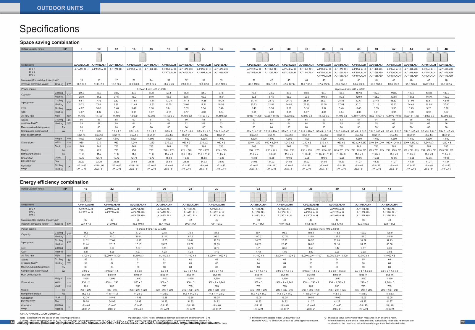
Specifications
HPRating Capacity range
m3/h
kW
kW
mm
mmmmmm
�C
W/W
dB(A)
kW
Capacity
Power source
PakW
kgkg
CoolingHeatingCoolingHeatingCoolingHeatingHighCoolingHeating
Cooling
Unit 1Unit 2Unit 3
Model name
Maximum Connectable Indoor Unit*1
Indoor unit connectable capacity
Input power
EERCOPAir flow rate
Dimensions
WeightRefrigerant charge
Connection pipe diameter
Operation range
Sound pressure level*2
Maximum external static pressureCompressor motor outputHeat exchanger fin
HeightWidthDepth
LiquidGasCoolingHeating
8
22.425.05.515.724.074.37
11,1005658803.9
Blue fin1,690930 76522011.2
12.7022.20
-15 to 46-20 to 21
1511.2-33.6
10
28.031.57.737.83 3.62 4.02
11,1005859803.9
Blue fin1,690 93076522011.2
12.7022.20
-15 to 46-20 to 21
1614.0-42.0
12
33.537.59.62 9.28 3.484.04
11,100586080
3.9 + 4.5Blue fin1,690 93076527511.8
12.7028.58
-15 to 46-20 to 21
1716.8-50.2
14
40.045.011.5311.453.473.93
13,000606180
3.9 + 4.5Blue fin1,690 1,24076529611.8
12.7028.58
-15 to 46-20 to 21
2120.0-60.0
16
45.050.014.1712.603.183.97
13,000616180
3.9 + 4.5Blue fin1,690 1,24076529611.8
12.7028.58
-15 to 46-20 to 21
2422.4-67.2
18
50.456.513.2413.55 3.81 4.17
11,100 x 2606280
3.9 x 2Blue fin1,690 930 x 2
765220 + 22011.2 x 215.8828.58
-5 to 46-20 to 21
3225.2-75.6
20
55.962.5
15.13 15.00 3.694.17
11,100 x 2606280
3.9 x 2 + 4.5Blue fin1,690
930 x 2765
275 + 22011.8 + 11.2
15.8828.58
-5 to 46-20 to 21
3228.0-83.9
22
61.569.0
17.35 17.11 3.54 4.03
11,100 x 2616380
3.9 x 2 + 4.5Blue fin1,690
930 x 2765
275 + 22011.8 + 11.2
15.8834.92
-5 to 46-20 to 21
3230.8-92.3
24
67.075.0
19.24 18.56 3.484.04
11,100 x 2616380
3.9 x 2 + 4.5 x 2Blue fin1,690
930 x 2765
275 + 27511.8 x 215.8834.92
-5 to 46-20 to 21
3533.5-100.5
36
100.5112.528.86 27.84 3.484.04
11,100 x 3636580
3.9 x 3 + 4.5 x 3Blue fin1,690 930 x 3
765275 + 275 + 275
11.8 x 319.0541.27
-5 to 46-20 to 21
4850.3-150.8
34
95.0106.526.97 26.39 3.524.04
11,100 x 3636480
3.9 x 3 + 4.5 x 2Blue fin1,690 930 x 3
765275 + 275 + 22011.8 x 2 + 11.2
19.0534.92
-5 to 46-20 to 21
4847.5-142.5
32
90.0100.028.3425.203.183.97
13,000 x 2646480
3.9 x 2 + 4.5 x 2Blue fin1,690
1,240 x 2 765
296 + 29611.8 x 219.0534.92
-5 to 46-20 to 21
4845.0-135.0
30
85.095.0
25.7024.053.313.95
13,000 x 2646480
3.9 x 2 + 4.5 x 2Blue fin1,690
1,240 x 2765
296 + 29611.8 x 219.0534.92
-5 to 46-20 to 21
4542.5-127.5
28
78.587.5
23.79 21.88 3.304.00
13,000 + 11,100636480
3.9 x 2 + 4.5 x 2Blue fin1,690
930 + 1,240765
296 + 27511.8 x 215.8834.92
-5 to 46-20 to 21
4239.3-117.8
26
73.582.5
21.15 20.73 3.483.98
13,000 + 11,100626480
3.9 x 2 + 4.5 x 2Blue fin1,690
930 + 1,240765
296 + 27511.8 x 215.8834.92
-5 to 46-20 to 21
3936.8-110.3
38
107.0120.030.77 30.01 3.484.00
13,000 + 11,100 × 2646580
3.9 x 3 + 4.5 x 3Blue fin1,690
930 x 2 + 1,240765
296 + 275 + 27511.8 x 319.0541.27
-5 to 46-20 to 21
4853.5-160.5
40
112.0125.033.41 31.16 3.354.01
13,000 + 11,100 × 2646580
3.9 x 3 + 4.5 x 3Blue fin1,690
930 x 2 + 1,240765
296 + 275 + 27511.8 x 319.0541.27
-5 to 46-20 to 21
4856.0-168.0
42
118.5132.535.32 33.33 3.363.98
13,000 × 2 + 11,100656580
3.9 x 3 + 4.5 x 3Blue fin1,690
930 + 1,240 x 2765
296 + 296 + 27511.8 x 319.0541.27
-5 to 46-20 to 21
4859.3-177.8
44
123.5137.537.96 34.48 3.253.99
13,000 × 2 + 11,100656580
3.9 x 3 + 4.5 x 3Blue fin1,690
930 + 1,240 x 2765
296 + 296 + 27511.8 x 319.0541.27
-5 to 46-20 to 21
4861.8-185.3
46
130.0145.039.8736.653.263.96
13,000 x 3656680
3.9 x 3 + 4.5 x 3Blue fin1,690
1,240 x 3765
296 + 296 + 29611.8 x 319.0541.27
-5 to 46-20 to 21
4865.0-195.0
48
135.0150.042.5137.803.183.97
13,000 x 3666680
3.9 x 3 + 4.5 x 3Blue fin1,690
1,240 x 3765
296 + 296 + 29611.8 x 319.0541.27
-5 to 46-20 to 21
4867.5-202.5
AJ*A72LALH
AJ*A72LALH
AJ*A90LALH
AJ*A90LALH
AJ*108LALH
AJ*108LALH
AJ*126LALH
AJ*126LALH
AJ*144LALH
AJ*144LALH
AJ*162LALH
AJ*A90LALHAJ*A72LALH
AJ*180LALH
AJ*108LALHAJ*A72LALH
AJ*198LALH
AJ*108LALHAJ*A90LALH
AJ*216LALH
AJ*108LALHAJ*108LALH
AJ*324LALH
AJ*108LALHAJ*108LALHAJ*108LALH
AJ*306LALH
AJ*108LALHAJ*108LALHAJ*A90LALH
AJ*288LALH
AJ*144LALHAJ*144LALH
AJ*270LALH
AJ*144LALHAJ*126LALH
AJ*252LALH
AJ*144LALHAJ*108LALH
AJ*234LALH
AJ*126LALHAJ*108LALH
AJ*342LALH
AJ*126LALHAJ*108LALHAJ*108LALH
AJ*360LALH
AJ*144LALHAJ*108LALHAJ*108LALH
AJ*378LALH
AJ*144LALHAJ*126LALHAJ*108LALH
AJ*396LALH
AJ*144LALHAJ*144LALHAJ*108LALH
AJ*414LALH
AJ*144LALHAJ*144LALHAJ*126LALH
AJ*432LALH
AJ*144LALHAJ*144LALHAJ*144LALH
HPRating Capacity range
m3/h
kW
kW
mm
mmmmmm
�C
W/W
dB(A)
kW
Capacity
Power source
PakW
kgkg
CoolingHeatingCoolingHeatingCoolingHeatingHighCoolingHeating
Cooling
Unit 1Unit 2Unit 3
Model name
Maximum Connectable Indoor Unit*1
Indoor unit connectable capacity
Input power
EERCOPAir flow rate
Dimensions
WeightRefrigerant charge
Connection pipe diameter
Operation range
Sound pressure level*2
Maximum external static pressureCompressor motor outputHeat exchanger fin
HeightWidthDepth
LiquidGasCoolingHeating
16
44.850.011.0211.444.074.37
11,100 x 2595980
3.9 x 2Blue fin1,690 930 x 2
765220 + 22011.2 x 212.7028.58
-5 to 46-20 to 21
3022.4-67.2
22
62.470.017.0417.173.664.08
13,000 + 11,100616280
3.9 x 2 + 4.5Blue fin1,690
930 + 1,240765
296 + 22011.8 + 11.2
15.8834.92
-5 to 46-20 to 21
3331.2-93.6
24
67.275.016.5317.164.074.37
11,100 x 3616180
3.9 x 3Blue fin1,690
930 x 3765
220 + 220 + 22011.2 x 315.8834.92
-5 to 46-20 to 21
3633.6-100.8
26
72.881.518.7519.27 3.88 4.23
11,100 x 3626280
3.9 x 3Blue fin1,690
930 x 3765
220 + 220 + 22011.2 x 315.8834.92
-5 to 46-20 to 21
3936.4-109.2
28
78.387.5
20.64 20.72 3.794.22
11,100 x 3626380
3.9 x 3 + 4.5Blue fin1,690
930 x 3765
275 + 220 + 22011.8 + 11.2 x 2
15.8834.92
-5 to 46-20 to 21
4239.2-117.4
30
84.895.0
22.5522.893.764.15
13,000 + 11,000 x 2636380
3.9 x 3 + 4.5Blue fin1,690
930 x 2 + 1,240765
296 + 220 + 22011.8 + 11.2 x 2
19.0534.92
-5 to 46-20 to 21
4542.4-127.2
44
125.0140.037.2335.503.363.94
13,000 x 3656680
3.9 x 3 + 4.5 x 3Blue fin1,690
1,240 x 3765
296 + 296 + 29611.8 x 319.0541.27
-5 to 46-20 to 21
4862.5-187.5
42
120.0135.034.5934.353.473.93
13,000 x 3656680
3.9 x 3 + 4.5 x 3Blue fin1,690
1,240 x 3765
296 + 296 + 29611.8 x 319.0541.27
-5 to 46-20 to 21
4860.0-180.0
40
113.5127.532.68 32.18 3.473.96
13,000 x 2 + 11,100646580
3.9 x 3 + 4.5 x 3Blue fin1,690
930 + 1,240 x 2765
296 + 296 + 27511.8 x 319.0541.27
-5 to 46-20 to 21
4856.8-170.2
36
102.4115.028.5728.623.584.02
13,000 x 2 + 11,100646580
3.9 x 3 + 4.5 x 2Blue fin1,690
930 + 1,240 x 2765
296 + 296 + 22011.8 x 2 + 11.2
19.0541.27
-5 to 46-20 to 21
4851.2-153.6
34
95.9107.526.66 26.45 3.604.06
13,000 + 11,100 x 2636480
3.9 x 3 + 4.5 x 2Blue fin1,690
930 x 2 + 1,240765
296 + 275 + 22011.8 x 2 + 11.2
19.0534.92
-5 to 46-20 to 21
4848.0-143.8
32
89.4 100.0 24.75 24.28 3.61 4.12
11,100 x 3626480
3.9 × 3 + 4.5 × 2Blue fin1,690
930 × 3765
275 + 275 + 22011.8 × 2 + 11.2
19.0534.92
-5 to 46-20 to 21
4844.7-134.1
AJ*144LALHH
AJ*A72LALHAJ*A72LALH
AJ*198LALHH
AJ*126LALHAJ*A72LALH
AJ*216LALHH
AJ*A72LALHAJ*A72LALHAJ*A72LALH
AJ*234LALHH
AJ*A90LALHAJ*A72LALHAJ*A72LALH
AJ*252LALHH
AJ*108LALHAJ*A72LALHAJ*A72LALH
AJ*270LALHH
AJ*126LALHAJ*A72LALHAJ*A72LALH
AJ*396LALHH
AJ*144LALHAJ*126LALHAJ*126LALH
AJ*378LALHH
AJ*126LALHAJ*126LALHAJ*126LALH
AJ*360LALHH
AJ*126LALHAJ*126LALHAJ*108LALH
AJ*324LALHH
AJ*126LALHAJ*126LALHAJ*A72LALH
AJ*306LALHH
AJ*126LALHAJ*108LALHAJ*A72LALH
AJ*288LALHH
AJ*108LALHAJ*108LALHAJ*A72LALH
3-phase 4 wire, 400 V, 50Hz 3-phase 4 wire, 400 V, 50Hz
3-phase 4 wire, 400 V, 50Hz3-phase 4 wire, 400 V, 50Hz
Space saving combination
Energy efficiency combination
Note : Specifications are based on the following conditions.Cooling : Indoor temperature of 27°CDB / 19°CWB, and outdoor temperature of 35°CDB / 24°CWB.Heating : Indoor temperature of 20°CDB / (15°CWB), and outdoor temperature of 7°CDB / 6°CWB.
Pipe length : 7.5 m; Height difference between outdoor unit and indoor unit : 0 m.When cooling operation will be conducted at outdoor air temperature below -5°C, the outdoor unit must be installed in a position that is higher than or equal to those of indoor units.
*2 The noise value is the value when measured in an anechoic room. When measured in the actual installed state, surrounding noise and reflections are received and the measured value is usually larger than the indicated value.
*1 Minimum connectable indoor unit number is 2. However ARXC72 and ARXC90 can be used signal connection.18 19
AJ* : AJY(FUJITSU), AJH(GENERAL)
OUTDOOR UNITS
Jäähdytinpalvelu RefGroup Oy, Kelatie 9 C, 01450 Vantaa, puh. 050 - 433 2222, fax 09 - 242 4277, [email protected], www.ilmalampopumput.com
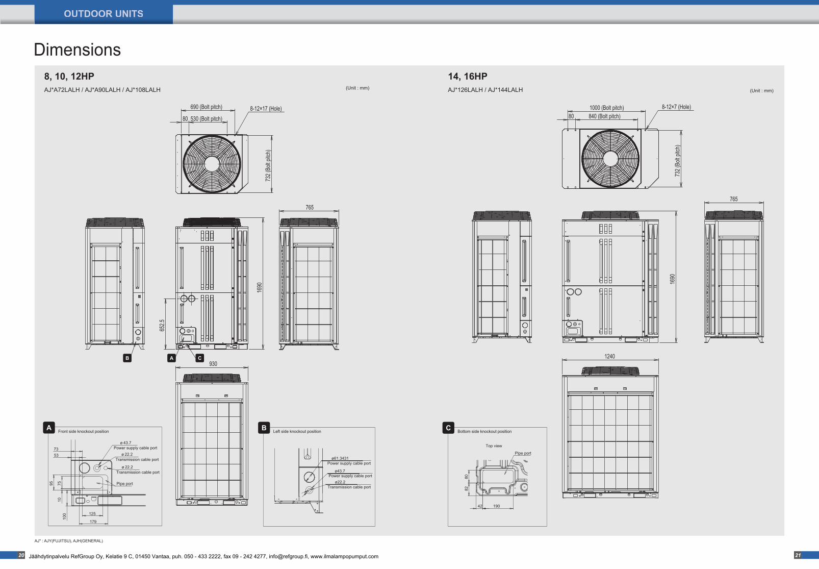
AJ*A72LALH / AJ*A90LALH / AJ*108LALH
8-12×17 (Hole)
1690
652.5
765
930
530 (Bolt pitch)80
690 (Bolt pitch)
(Unit : mm) (Unit : mm)
732 (
Bolt p
itch)
8-12×7 (Hole)
1240
1690
765
732 (
Bolt p
itch)
1000 (Bolt pitch)840 (Bolt pitch)80
ø43.7
ø22.2Transmission cable port
Power supply cable portø61.3431
80
190
82
42
Pipe port
100
5373
7595
179
ø 43.7
ø 22.2
ø 22.2
125
Pipe port
Power supply cable port
Transmission cable port
Transmission cable port
10
A B Bottom side knockout positionCFront side knockout position Left side knockout position
Top view
CAB
Power supply cable port
AJ* : AJY(FUJITSU), AJH(GENERAL)
Dimensions8, 10, 12HP
AJ*126LALH / AJ*144LALH
14, 16HP
20 21
OUTDOOR UNITS
Jäähdytinpalvelu RefGroup Oy, Kelatie 9 C, 01450 Vantaa, puh. 050 - 433 2222, fax 09 - 242 4277, [email protected], www.ilmalampopumput.com
INDOOR UNITS
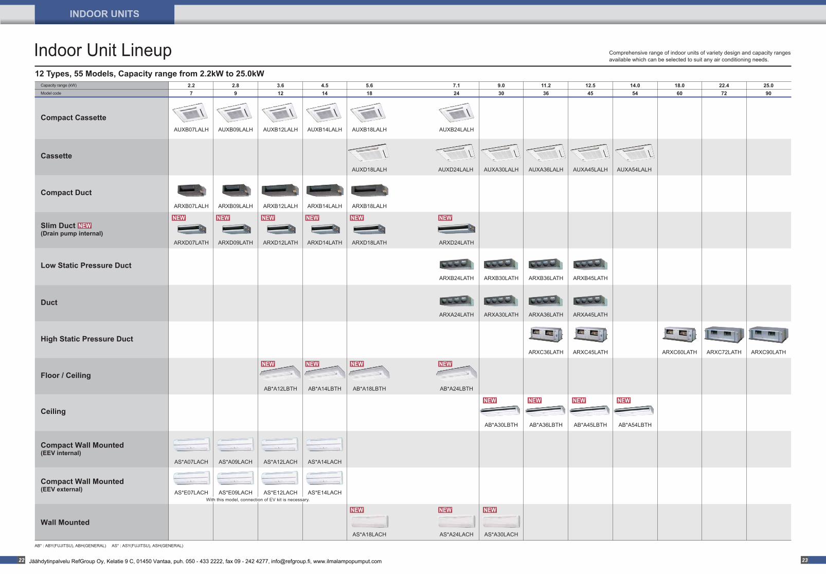
Comprehensive range of indoor units of variety design and capacity ranges available which can be selected to suit any air conditioning needs.
Compact Cassette
Cassette
Compact Duct
Slim Duct(Drain pump internal)
Low Static Pressure Duct
High Static Pressure Duct
Duct
Floor / Ceiling
Ceiling
2.2Capacity range (kW)
Model code
2.8 3.6 4.5 5.6 7.1 11.29.0 12.5 14.0 18.0 22.4 25.07 9 12 14 18 24 3630 45 54 60 72 90
AUXB07LALH AUXB09LALH AUXB12LALH AUXB14LALH AUXB18LALH
AUXD18LALH
ARXB07LALH ARXB09LALH ARXB12LALH ARXB14LALH
AS*E07LACH AS*E09LACH AS*E12LACH AS*E14LACH
ARXB18LALH
AS*A18LACH
AB*A12LBTH AB*A14LBTH AB*A18LBTH AB*A24LBTH
AUXD24LALH
AUXB24LALH
AUXA45LALHAUXA36LALH AUXA54LALH
ARXB30LATH
AUXA30LALH
ARXB24LATH ARXB36LATH ARXB45LATH
ARXA30LATHARXA24LATH ARXA36LATH ARXA45LATH
ARXC36LATH ARXC45LATH ARXC60LATH ARXC72LATH ARXC90LATH
AB*A30LBTH AB*A36LBTH AB*A45LBTH AB*A54LBTH
Compact Wall Mounted(EEV internal)
Wall Mounted
Compact Wall Mounted(EEV external)
AS*A07LACH AS*A09LACH AS*A12LACH AS*A14LACH
ARXD07LATH ARXD09LATH ARXD12LATH ARXD14LATH ARXD18LATH ARXD24LATH
AS*A30LACHAS*A24LACH
Indoor Unit Lineup12 Types, 55 Models, Capacity range from 2.2kW to 25.0kW
AB* : ABY(FUJITSU), ABH(GENERAL) AS* : ASY(FUJITSU), ASH(GENERAL)
With this model, connection of EV kit is necessary.
22 23Jäähdytinpalvelu RefGroup Oy, Kelatie 9 C, 01450 Vantaa, puh. 050 - 433 2222, fax 09 - 242 4277, [email protected], www.ilmalampopumput.com

A
B
C
D
Grille cover2
1
3
Models: AUXB07 / AUXB09 / AUXB12 / AUXB14 / AUXB18 / AUXB24
Dimensions (Unit : mm)
Adoption of laminar wing
Spin direction
Airflow direction
Quiet
Airflow runs through smoothly along the laminar wing
No airflow separation
Laminar wingQuiet
High efficiency design by 2 stage structure
Previous turbo fan
Heat exchangeefficiency
20%UP
1-stage 2-stage turbo fan
+ =2-stage
Designed by CFD-analysis (fluid) simulations
Compact Cassette
Compact size panel design that fits standard ceiling panel (600x600mm)
ModelsAUXB07LALHAUXB09LALHAUXB12LALHAUXB14LALHAUXB18LALHAUXB24LALH
2-stage turbo fan Quiet quality
Improvement of the airflow distribution
Compact design
High lift drain pump
During installation, maintenance and operation, the drain pump and kit can be checked easily.
A : Fan motorC : Bell-mouth
B : 2-stage turbo fanD : Panel
1 Maintenance of fan motor and fan
2 Long life filter : standard equipment
3 Adaptation of transparent drainage parts
Maintenance of the fan motor and fan can be done easily after taking off the panel as the bell mouth of the fan can be removed easily.
Worlds first 24,000Btu model in the compact cassette category (Easy installation by taking off ceiling panel of 600 x 600 size)
Optimization of wing form (laminar wing type) and wing number (7 blades each)
An evenly spread air distribution across the heat exchanger is possible due to the new 2 stage turbo fan which produces two separate airflow streams.
In the case of a previous fan, the air outlet range was narrow as the airflow moved to the motor side which meant the velocity of air passing through the heat exchanger was uneven.
070912141824
Model code
2.72.72.72.72.72.7
Standard mode--3.03.03.03.0
High ceiling modeThe maximum height from floor to ceiling (m)
High ceiling modeThe compact cassette can be installed up to a height of 3.0m (12/14/18/24).
570mm570mm
Fast
Slow
Wind velocity
Ceiling panelHeight
700mm
700
30 4970
0
530 (Bolt pitch)
540
(Bol
t pitc
h)
570
(Indo
or u
nit)
580-
660
(Cei
ling
open
ings
)
75
116
222 26
2
58 124
135 250
Control box
Liquid pipe Gas pipe
Ceiling
Side view
Top view
Side view
Bottom view
30
9940250135
102
108
146
40
245
Optional parts
Air Outlet Shutter Plate :Insulation Kit for High Humidity :Fresh Air Intake Kit :
UTR-YDZBUTZ-KXGCUTZ-VXAA
2.2
2.8
25
540
450
350
34
30
25
AUXB07LALH AUXB09LALH AUXB12LALH AUXB18LALHAUXB14LALH
Cooling
Heating
High
Med
Low
High
Med
Low
Liquid (Flare)
Gas (Flare)
Drain
2.8
3.2
25
550
450
350
35
30
25
4.5
5.0
35
680
590
390
38
34
27
5.6
6.3
36
710
580
400
41
35
27
7.1
8.0
84
1,030
830
450
50
44
30
3.6
4.1
29
600
530
390
37
34
27
kW
W
m3/h
dB(A)
mm
kg
mm
mm
kg
Model name
Power source
Capacity
Input power
Airflow rate
Sound pressure level
Dimensions (H x W x D)
Weight
Connection pipe diameter
Grille(option)
F* : FY (FUJITSU) ; FG(GENERAL)Note : Specifications are based on the following conditions.
Cooling : Indoor temperature of 27�CDB / 19�CWB, and outdoor temperature of 35�CDB / 24�CWB.Heating : Indoor temperature of 20�CDB / (15�CWB), and outdoor temperature of 7�CDB / 6�CWB.Pipe length : 7.5 m; Height difference between outdoor unit and indoor unit : 0 m. Voltage : 230 [V].
15
ø6.35
ø12.70
AUXB24LALH
245 x 570 x 570
UTG-UF*C-W
50 x 700 x 700
2.6
17
ø9.52
ø15.88
230V ~, 50Hz
ø25 (I.D) ; ø32 (O.D.)
Model name
Dimensions (H x W x D)
Weight
Specifications
24 25
INDOOR UNITS
Jäähdytinpalvelu RefGroup Oy, Kelatie 9 C, 01450 Vantaa, puh. 050 - 433 2222, fax 09 - 242 4277, [email protected], www.ilmalampopumput.com
182430364554
Model code
3.03.03.23.23.23.2
Standard mode3.53.53.64.24.24.2
High ceiling modeThe maximum height from floor to ceiling (m)
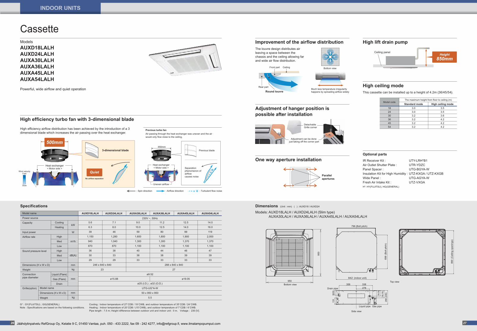
Models: AUXD18LALH / AUXD24LALH (Slim type) AUXA30LALH / AUXA36LALH / AUXA45LALH / AUXA54LALH
Cassette
Dimensions (Unit : mm) ( ) : AUXD18 / AUXD24
High efficiency turbo fan with 3-dimensional bladeDetachable Grille corner
Adjustment can be done just taking off the corner part
Parallel apertures
450mm
Heat exchanger< Motor side >
Uneven airflow
Separation phenomenon of airflow causes noise
: Spin direction : Airflow direction : Turbulent flow noise
< Motor side >Heat exchanger
3-dimensional blade
High efficiency airflow distribution has been achieved by the introduction of a 3 dimensional blade which increases the air passing over the heat exchanger.
Previous blade
500mm
No airflow separation
Quiet
Ceiling panel
Improvement of the airflow distribution
Adjustment of hanger position is possible after installation
One way aperture installation
High lift drain pump
High ceiling mode
The louvre design distributes air leaving a space between the chassis and the ceiling allowing far and wide air flow distribution.
This cassette can be installed up to a height of 4.2m (36/45/54).Much less temperature irregularity happens by spreading airflow widely
Bottom viewFront part Ceiling
Rear part
Round louvre
Optional parts
IR Receiver Kit :Air Outlet Shutter Plate :Panel Spacer :Insulation Kit for High Humidity :Wide Panel :Fresh Air Intake Kit :
UTY-LRH*B1UTR-YDZCUTG-BGYA-WUTZ-KXGA / UTZ-KXGBUTG-AGYA-WUTZ-VXGA
H*: HY(FUJITSU), HG(GENERAL)
358
98(5
6)13
3
118 (7
6)
158 (
116)
288
(246
)
Drain pipe
Liquid pipe
Side view
Top view
Gas pipe
338278
950
950Bottom view
890
(Cei
ling
open
ings
)
699
(Bol
t pitc
h)
796 (Bolt pitch)
842 (indoor unit)
Height850mm
Powerful, wide airflow and quiet operation
ModelsAUXD18LALHAUXD24LALHAUXA30LALH AUXA36LALHAUXA45LALHAUXA54LALH
Previous turbo fanAir passing through the heat exchanger was uneven and the air would only flow close to the ceiling.
Fast
Slow
Wind velocity
5.6
6.3
39
1,150
940
870
36
30
29
Cooling
Heating
High
Med
Low
High
Med
Low
Liquid (Flare)
Gas (Flare)
Drain
kW
W
m3/h
dB(A)
mm
mm
mm
kg
kg
Model name
Power source
Capacity
Input power
Airflow rate
Sound pressure level
Dimensions (H x W x D)
Weight
Connection pipe diameter
Grille(option)
G* : GY(FUJITSU) ; GG(GENERAL)Note : Specifications are based on the following conditions.
Cooling : Indoor temperature of 27�CDB / 19�CWB, and outdoor temperature of 35�CDB / 24�CWB.Heating : Indoor temperature of 20�CDB / (15�CWB), and outdoor temperature of 7�CDB / 6�CWB.Pipe length : 7.5 m; Height difference between outdoor unit and indoor unit : 0 m. Voltage : 230 [V].
AUXD18LALH
230V ~, 50Hz
AUXD24LALH AUXA30LALH AUXA45LALHAUXA36LALH AUXA54LALH
246 x 840 x 840
23
288 x 840 x 840
27
ø9.52
ø25 (I.D.) ; ø32 (O.D.)
UTG-UG*A-W
50 x 950 x 950
5.5
Model name
Dimensions (H x W x D)
Weight
Specifications
9.0
10.0
59
1,600
1,300
1,100
40
38
33
11.2
12.5
80
1,800
1,300
1,100
44
38
33
14.0
16.0
119
2,000
1,370
1,100
47
39
33
7.1
8.0
46
1,280
1,040
870
38
33
29
ø15.88
12.5
14.0
99
1,900
1,370
1,100
46
39
33
ø19.05
26 27
INDOOR UNITS
Jäähdytinpalvelu RefGroup Oy, Kelatie 9 C, 01450 Vantaa, puh. 050 - 433 2222, fax 09 - 242 4277, [email protected], www.ilmalampopumput.com
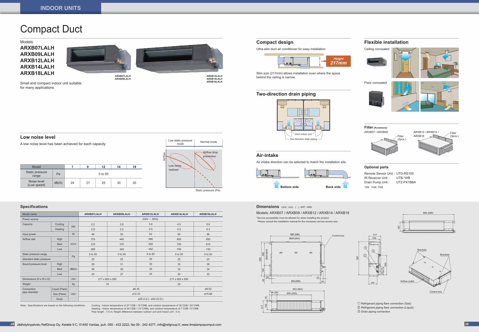
Slim size (217mm) allows installation even where the space behind the ceiling is narrow.
Compact design
Low noise level
Refrigerant piping flare connection (Gas)Refrigerant piping flare connection (Liquid)Drain piping connection
21
3
Models: ARXB07 / ARXB09 / ARXB12 / ARXB14 / ARXB18*Service accessibility must be allowed for when installing the product. Please consult the installation manual for the necessary service access size.
Two-direction drain piping
Two-direction drain piping
Duct indoor unitFilter (2pcs.)
ARXB07 / ARXB09 ARXB12 / ARXB14 / ARXB18
Filter (3pcs.)
7 9
0 to 50
27
Pa
dB(A)
Static pressurerange
Noise level(Low speed)
30
Model
24 25 30
12 14 18
A low noise level has been achieved for each capacity
Ultra-slim duct air conditioner for easy installation
Static pressure (Pa)
Low static pressuremode
Normal mode
Airflow drop prevention
Low noise realized
Airf
low
2
13
Control box
Brackets
Brackets
Airflow outlet
Control box
886(Bolt pitch)
(Bol
t pitc
h)
(596)
850 (560)
390
166
595
20
24 47
85
587
194
150
7565
344
953 (663)
600 (400)94 (50)
1021
715
0
886 (596)
167
217
Compact Duct
Small and compact indoor unit suitable for many applications
ModelsARXB07LALHARXB09LALHARXB12LALHARXB14LALHARXB18LALH
Refrigerant piping flare connection (Gas)Refrigerant piping flare connection (Liquid)Drain piping connection
21
3
Models: ARXB07 / ARXB09 / ARXB12 / ARXB14 / ARXB18*Service accessibility must be allowed for when installing the product. Please consult the installation manual for the necessary service access size.
2
13
Control box
Brackets
Brackets
Airflow outlet
Control box
886(Bolt pitch)
(Bol
t pitc
h)
(596)
850(560)
390
166
595
20
24 47
85
587
194
150
7565
344
953 (663)
600 (400)94 (50)
1021
715
0
886 (596)
167
217
Dimensions (Unit : mm) ( ) : AR7 / AR9
Air-intake
Back sideBottom side
Air intake direction can be selected to match the installation site.
Height217mm
Flexible installation
Floor concealed
Ceiling concealed
Filter (Accessory)
Optional parts
Remote Sensor Unit :IR Receiver Unit :Drain Pump Unit :
UTD-RS100UTB-*WBUTZ-PX1BBA
*WB : YWB, TWB
ARXB07LALHARXB09LALH
ARXB12LALHARXB14LALHARXB18LALH
2.2
2.8
46
370
310
280
0 to 50
25
29
26
24
ARXB07LALH ARXB09LALH ARXB12LALH ARXB18LALHARXB14LALH
Cooling
Heating
High
Med
Low
High
Med
Low
Liquid (Flare)
Gas (Flare)
Drain
2.8
3.2
55
440
370
340
0 to 50
25
31
29
27
4.5
5.0
90
800
750
700
0 to 50
25
33
32
30
217 x 953 x 595
25
5.6
6.3
96
890
810
730
0 to 50
25
36
34
30
ø9.52
ø15.88
230V ~, 50Hz
3.6
4.0
63
590
500
450
0 to 50
25
30
28
25
ø25 (I.D.) ; ø32 (O.D.)
kW
W
m3/ h
Pa
dB(A)
mm
kg
mm
Model name
Power source
Capacity
Input power
Airflow rate
Static pressure range
Standard static pressure
Sound pressure level
Dimensions (H x W x D)
Weight
Connectionpipe diameter
217 x 663 x 595
18
ø6.35
ø12.70
Note : Specifications are based on the following conditions. Cooling : Indoor temperature of 27�CDB / 19�CWB, and outdoor temperature of 35�CDB / 24�CWB.Heating : Indoor temperature of 20�CDB / (15�CWB), and outdoor temperature of 7�CDB / 6�CWB.Pipe length : 7.5 m; Height difference between outdoor unit and indoor unit : 0 m.
Specifications
28 29
INDOOR UNITS
Jäähdytinpalvelu RefGroup Oy, Kelatie 9 C, 01450 Vantaa, puh. 050 - 433 2222, fax 09 - 242 4277, [email protected], www.ilmalampopumput.com