multi-aspirator - kicekice industries, inc. 4 important write down the model and serial number of...
TRANSCRIPT
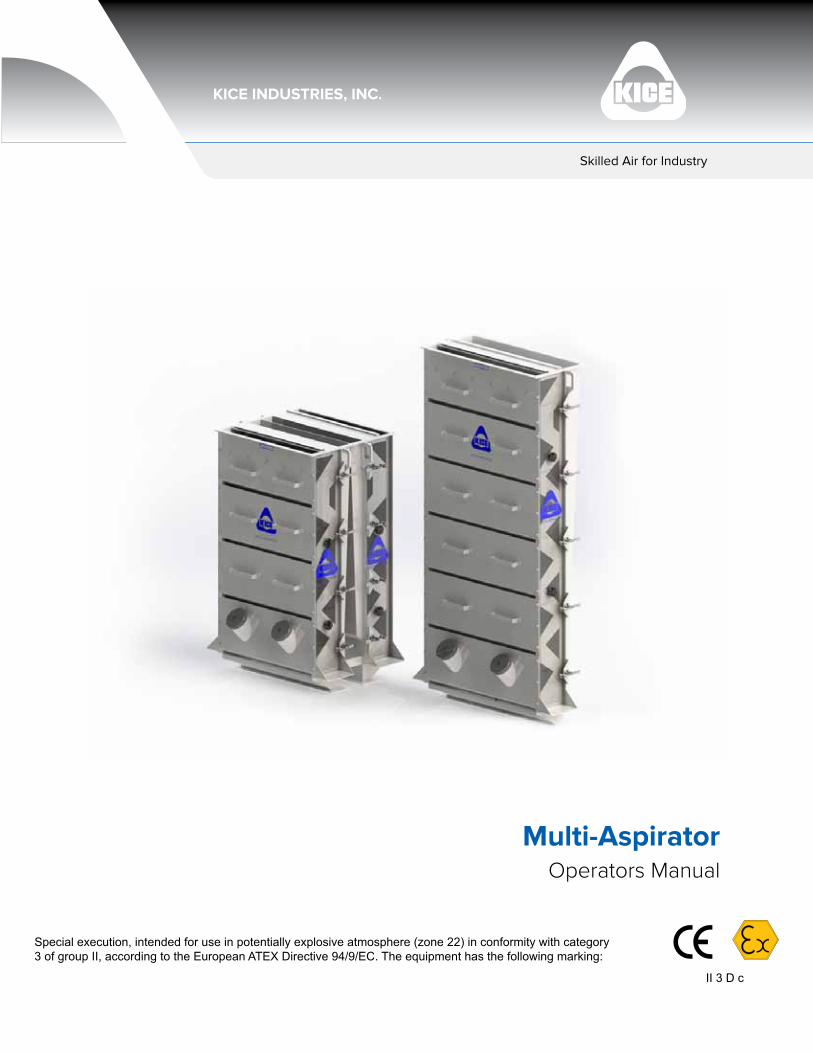
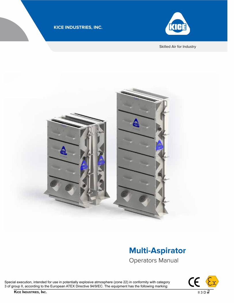
Operators ManualMulti-Aspirator
Skilled Air for Industry
II 3 D c
2Kice industries, inc.
Skilled Air for Industry
Special execution, intended for use in potentially explosive atmosphere (zone 22) in conformity with category 3 of group II, according to the European ATEX Directive 94/9/EC. The equipment has the following marking:
II 3 D c
Operators ManualMulti-Aspirator
3Kice industries, inc.
IntroductIon
When you purchased your Kice Multi-Aspirator, you bought an air classifier that has proven to be the best design based on thousands of installations and years of proven reliability and operation.
We are proud of our products and the people at Kice Industries who build them. At Kice, we start with the highest quality raw materials and follow the construction standards and manufacturing techniques that have proven superior over the last 60 years.
The results of our development work and input from users have resulted in the present design of the Kice Multi-Aspirators.
This owner’s manual is intended as a guide for proper installation, operation and maintenance to keep your Kice Multi-Aspirator operating safely and efficiently on the job. Service and spare parts information is also included for your benefit.
Sincerely,
Drew Kice, PresidentKice Industries, Inc.
Warranty
Limited Warranty and Limitations of Warranty: Kice warrants the equipment manufactured by Kice to be free of defects in material and workmanship for a period of one (1) year from the date of shipment. Kice agrees to repair or replace, at its discretion, any parts found to be defective in the opinion of Kice. Kice is not liable for any costs in connection with the removal, shipment or reinstallation of said parts. This warranty does not apply to abrasion, corrosion, erosion, abuse or misuse of the product. Assistance by Kice in system layout or selecting equipment does not imply Kice’s responsibility. Buyer agrees to look to the warranty, if any, of the manufacturer or supplier of products manufactured by others and supplied by Kice for any alleged defects in such products and for any damages or injuries caused thereby or as a result thereof. Where work is made to measurements or specifications furnished by the Buyer, Kice does not assume any responsibility for the accuracy of Buyer’s specifications. Kice will not assume responsibility for alteration or repairs unless the same are made with the written consent and approval of Kice.
BUYER SHALL BE RESPONSIBLE FOR COMPLIANCE WITH ELECTRICAL MANUFACTURER’S RECOMMENDATIONS, UNDERWRITERS CODE AND ALL SAFETY PRECAUTIONS.
Kice extends no other warranty for any of its products other than the above express warranty, and there are no other warranties, express or implied, including warranties of merchantability, fitness for a particular purpose or otherwise which extend beyond the above limited express warranty. Kice and its dealers shall not in any event be liable for consequential or incidental damages, and this agreement provides buyer’s sole and exclusive remedy. Any actions for breach of this agreement or warranty must be commenced within one year after the cause of action has occurred.
4Kice industries, inc.
important
Write down the MODEL and SERIAL NUMBER of the Kice Multi-Aspirator, along with the same information for the auxiliary equipment (i.e., fan, cyclone, filter, airlock valve, etc.).
For additional information, application assistance or special service, you should contact the factory. We will need to know the MODEL and SERIAL NUMBER of your Multi-Aspirator. For ready reference, please record this information and the date of delivery or installation on the lines below. See the General Information section for the location of the model and serial number.
MODEL
SERIAL NUMBER
Date of delivery or installation / /
table of contents
introduction...................................................................................................................................... 2
1. General information...................................................................................................................... 4
2. safety precautions....................................................................................................................... 6
3. multi-aspirator information and operatinG instructions............................................................... 8
4. start-up procedure.................................................................................................................... 12
5. maintenance................................................................................................................................. 12
6. troubleshootinG.......................................................................................................................... 13
7. special ateX information........................................................................................................... 14
8. torque Values for maintenance and installation........................................................................ 15
9. illustrated parts list................................................................................................................. 16
10. operation of 6dt8 lab and 6dt8 production units................................................................. 17
11. additional equipment from Kice industries, inc. ....................................................................... 18
5Kice industries, inc.
1. General InformatIon
to the neW oWner
The purpose of this manual is to assist owners and operators in maintaining and operating the Kice Multi-Aspirator System. Please read it carefully; information and instructions furnished can help you achieve years of dependable performance. Separate manuals are included for auxiliary equipment, such as airlock valves, fans, cyclones and filters. They contain additional information that may not be repeated in this manual. You are urged to read all manuals before attempting any operation or repair of the equipment in the system. If these manuals are not included in your owner’s packet, contact our customer service department. Along with surprisingly complete separation of closely related particles, some fringe benefits are often obtained which add to the desirability of the system. These benefits include:
1. Cooling of the aspirated stock, depending on particle size and temperature differential of air and stock.
2. Conveying of the liftings to the desired destination by the same air that lifts the fines from the stock3. Virtually no operator or maintenance attention is required because of the simplicity of the unit. Once
a uniform spread of stock is attained and the air volume is adjusted to lift the desired particles, the unit will consistently remove the majority of these particles that are present in the incoming product.
usinG this manual
General operation, adjustment and maintenance guidelines are outlined for owners and operators of Kice Multi-Aspirator systems. Operating conditions vary considerably and cannot be addressed individually. Through experience, however, operators should have no difficulty in developing good operating, safety and monitoring skills. The term “disconnect and lockout” as used in this manual means that power to the equipment has been disconnected through the use of a padlockable, manual, power cutoff, or power lockout switch. Directions used in this manual, for example RIGHT or LEFT, CLOCKWISE or COUNTERCLOCKWISE, refer to directions when facing the front (air inlet) side of the Multi-Aspirator or looking down in plan view.
Photographs and illustrations were current at the time of printing, but subsequent production changes may cause your Multi-Aspirator to vary slightly in detail. Kice Industries, Inc., reserves the right to redesign and change the equipment as deemed necessary, without notification. If a change has been made to your Kice Multi-Aspirator that is not reflected in this owner’s manual or the illustrated parts list, write or call Kice Industries, Inc., for current information and parts.

6Kice industries, inc.
General information continued
model and serial number
The Kice Multi-Aspirator model and serial number can be found stamped on the metal identification plate located on the back of the Multi-Aspirator (just below the air outlet flange).
Identification Plate Examples
Kice multi-aspirator parts and serVice
Use original Kice Multi-Aspirator replacement parts only. These parts are available from Kice Industries, Inc. To obtain prompt, efficient service, always provide the following information when ordering parts:
1. Correct part description and number, as given in the Illustrated Parts List section of this manual2. Correct model number3. Correct serial number
For assistance in service or ordering parts, contact the customer service department at Kice Industries, Inc., 5500 Mill Heights Drive, Wichita, KS 67219-2358, Phone 316-744-7151, and Fax 316-744-7355.
IMPORTANT: Any unauthorized modification, alteration, or use of non-approved attachments voids the warranty and releases Kice Industries, Inc., from any liability arising from subsequent use of the equipment. Each type of Multi-Aspirator is designed to be used with a specific type and quantity of material. Using the Multi-Aspirator for any purpose other than that for which it was designed could result in reduced aspiration performance or personal injury, as well as, product or property damage.
for motor and speed reducer parts and serVice Any motor or speed reducer associated with the Kice Multi-Aspirator system is covered by the manufacturer’s warranty. If there is a problem, check with the local supplier or service representative.
7Kice industries, inc.
2. safety PrecautIons
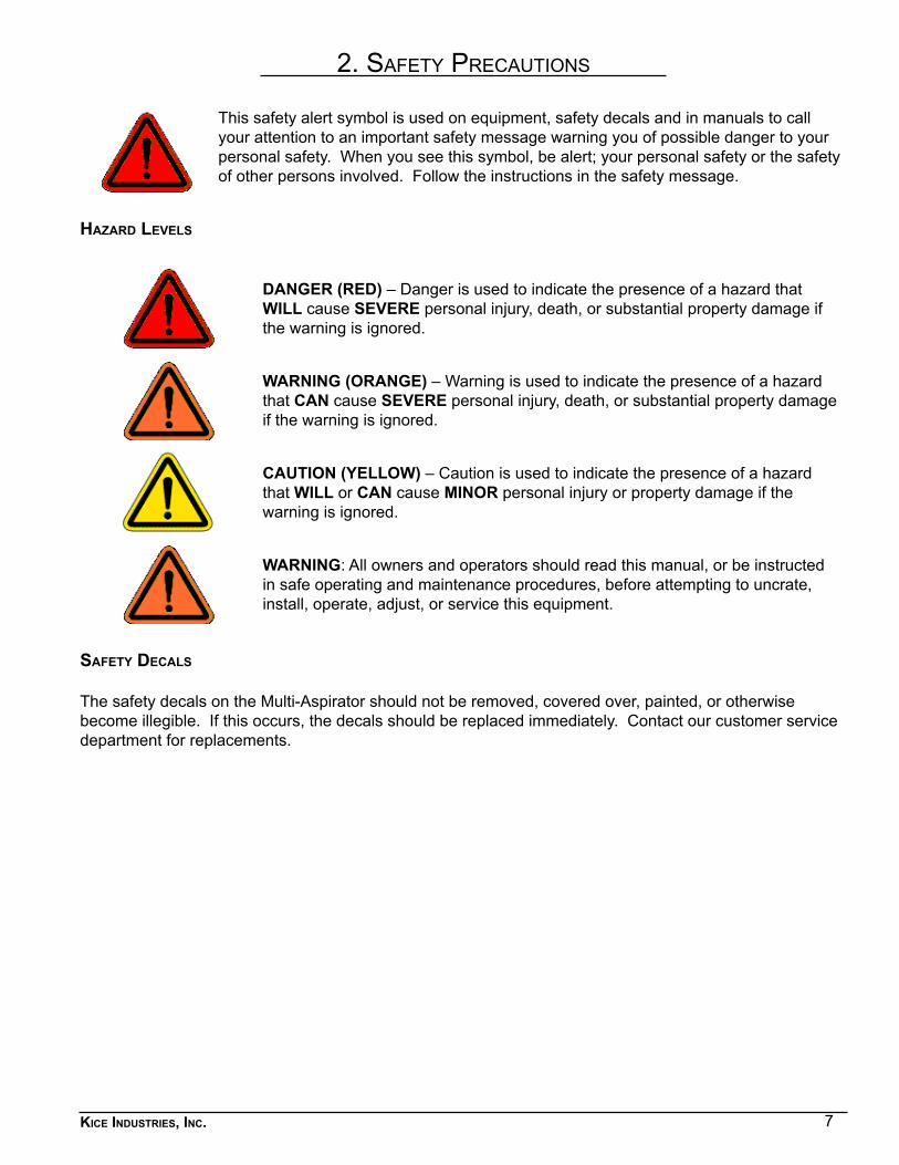
This safety alert symbol is used on equipment, safety decals and in manuals to call your attention to an important safety message warning you of possible danger to your personal safety. When you see this symbol, be alert; your personal safety or the safety of other persons involved. Follow the instructions in the safety message.
hazard leVels
DANGER (RED) – Danger is used to indicate the presence of a hazard that WILL cause SEVERE personal injury, death, or substantial property damage if the warning is ignored.
WARNING (ORANGE) – Warning is used to indicate the presence of a hazard that CAN cause SEVERE personal injury, death, or substantial property damage if the warning is ignored.
CAUTION (YELLOW) – Caution is used to indicate the presence of a hazard that WILL or CAN cause MINOR personal injury or property damage if the warning is ignored.
WARNING: All owners and operators should read this manual, or be instructed in safe operating and maintenance procedures, before attempting to uncrate, install, operate, adjust, or service this equipment.
safety decals
The safety decals on the Multi-Aspirator should not be removed, covered over, painted, or otherwise become illegible. If this occurs, the decals should be replaced immediately. Contact our customer service department for replacements.
8Kice industries, inc.
safety precautions continued
1. Do not attempt to install, operate or service your new Multi-Aspirator without proper instruction and until you have been thoroughly trained in its use by your employer.
2. The unit must be lifted by a means with sufficient lifting capacity.3. The Kice Multi-Aspirator is fully encapsulated if properly connected during installation.4. Operate the Multi-Aspirator (including upstream and downstream components only after all pipes or
hoses have been connected.5. When installed, the unit must be separately grounded.6. Do not manually override or electrically bypass any protective device.7. If the Multi-Aspirator is equipped with a maintenance panel or access door incorporating a Protective
Interlocking Limit Switch (PLS), the PLS must be interlocked with all electrical controls. This is to prevent all motors or powered devices associated with the unit from being energized if any protective cover, guard, grate or maintenance panel is open or removed. Never attempt to manually override or electrically bypass a safety device. The interlock function of the PLS must be tested and logged daily by supervisory personnel.
8. It is the owner’s and the employer’s responsibility to adequately train the employee-operator in the proper and safe use of the equipment. Written safety programs and formal instruction are essential. All new employees must be made aware of company policies and operating rules, especially the established safety and health procedures. Refresher training of experienced employees in the potential hazards of the job is important. Up-to-date training records must be maintained at the job site.
9. Special attention must be devoted to outside contractors engaged to enter and perform work on equipment or in the workplace. Special care must be exercised to insure all such personnel are fully informed of the potential hazards and follow plant rules – with special emphasis on explosion proof electrical tools and cutting or welding in unsafe environments.
10. Keep the workplace cleaned up and free of dirt and dust at all times. Do not attempt to work on slippery or unsafe ladders or work platforms when maintenance or repair work is being performed on the Multi-Aspirator.
11. Do not climb on ladders or work on platforms unless maximum load rating is posted. Do not exceed maximum load ratings when installing or servicing the Multi-Aspirator.
12. Never allow any kind of metal or other foreign objects to enter a Multi-Aspirator while in operation, unless the system is specifically designed as a wire or metal reclaim system.
13. The Kice Multi-Aspirator has no moving parts. Therefore, access into the machine is not restricted. However, in some installations, there is a machine metering the material into the Multi-Aspirator and/or a machine discharging the material from the Multi-Aspirator. The accessory machinery feeding and discharging the material may be dangerous to personnel working on or around the Multi-Aspirator.
14. Operate safely at all times. Use personal protective equipment when and where appropriate, such as hard hats, helmets, gloves, earplugs, and eye protection devices. Keep personal protective equipment in good repair and convenient to the operator.
15. When carrying out cleaning, service or maintenance activities a dust mask should be worn. 16. The operator of the Multi-Aspirator must ensure that adequate lighting conditions are provided at the
set-up location.17. It is ultimately the operator’s responsibility to implement the above listed precautions and insure proper
equipment use, maintenance and lubrication. Keep these instructions and list of warnings with your machine at all times.
18. There is a separate ignition source analysis for the Kice Multi-Aspirator, where all dangers concerning explosion protection are considered.
WORK SAFELY AT ALL TIMES
9Kice industries, inc.
3. multI-asPIrator InformatIon and oPeratInG InstructIons
receiVinG and inspection
Kice Industries, Inc. has prepared your new Multi-Aspirator for shipment in accordance with the Uniform Freight Classification. It has been thoroughly inspected at the factory and, barring damage in transit, should be in excellent condition upon arrival. The Kice Multi-Aspirator and accessory equipment should be inspected upon receipt for any shipping damage. If dampers or shutters are provided, check these accessories for free operation of all moving parts. When a carrier signs the Kice Industries, Inc., bill of lading, the carrier accepts the responsibility for any subsequent shortages or damage, evident or concealed, and any claim must be made against the carrier by the purchaser. Evident shortage or damage should be noted on the carrier’s delivery document before signature of acceptance. Inspection by the carrier of damage, evident or concealed, must be requested. After inspection, issue a purchase order for necessary parts or arrange for return of the equipment to Kice Industries, Inc., for repair.
handlinG and storaGe
Kice Multi-Aspirators are shipped completely assembled and skidded when size permits. These units may be handled and moved using good rigging techniques, being careful to avoid concentrated stresses that will distort any of the parts. Items or parts of the Multi-Aspirator that are shipped separately (knocked down) will be clearly labeled for reassembly. If the Kice Multi-Aspirator is not to be installed promptly, store it in a clean, dry location to prevent rust and corrosion of steel components. If outdoor storage is necessary, protection should be provided. Cover the inlets and outlets to prevent the accumulation of dirt and moisture inside the unit. Refer to the maintenance section of this manual regarding any further storage instructions.
10Kice industries, inc.
multi-aspirator information and operatinG instructions continued
multi-aspirator installation
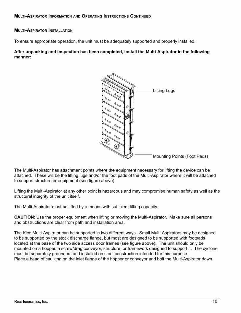
To ensure appropriate operation, the unit must be adequately supported and properly installed.
After unpacking and inspection has been completed, install the Multi-Aspirator in the following manner:
The Multi-Aspirator has attachment points where the equipment necessary for lifting the device can be attached. These will be the lifting lugs and/or the foot pads of the Multi-Aspirator where it will be attached to support structure or equipment (see figure above).
Lifting the Multi-Aspirator at any other point is hazardous and may compromise human safety as well as the structural integrity of the unit itself.
The Multi-Aspirator must be lifted by a means with sufficient lifting capacity.
CAUTION: Use the proper equipment when lifting or moving the Multi-Aspirator. Make sure all persons and obstructions are clear from path and installation area. The Kice Multi-Aspirator can be supported in two different ways. Small Multi-Aspirators may be designed to be supported by the stock discharge flange, but most are designed to be supported with footpads located at the base of the two side access door frames (see figure above). The unit should only be mounted on a hopper, a screw/drag conveyor, structure, or framework designed to support it. The cyclone must be separately grounded, and installed on steel construction intended for this purpose. Place a bead of caulking on the inlet flange of the hopper or conveyor and bolt the Multi-Aspirator down.
Lifting Lugs
Mounting Points (Foot Pads)
11Kice industries, inc.
multi-aspirator information and operatinG instructions continued
The Multi-Aspirator should be installed in a level position to prevent material from flowing to one side of the unit. The incoming stock MUST be evenly spread across the full width of the Multi-Aspirator. This is accomplished by feeding the stock into the unit in such a manner that one part of the Multi-Aspirator does not receive a larger percentage of the stock than any other part. On Multi-Aspirators wider than 24”, the stock should be split and enter at more than one point or have special inlet transitions to insure a uniform spread. NOTE: The stock inlet connection and/or associated gravity spouting and the air outlet connection should brace the Multi-Aspirator. Product inlet or outlet transitions are not designed to support the weight of the Multi-Aspirator or of accessory equipment such as an airlock valve or a rotary stream splitter. If the unit is installed outdoors, cross bracing from the angle iron frame may be required for wind loading connections.
Proper installation of the Kice Multi-Aspirator also includes assembling the duct work and required machinery to the unit, fully enclosing it for quality operation. The unit should only be operated once it is properly connected and fully encapsulated. All duct work or stacks should be independently supported as excess weight may distort the system causing improper airflow, affecting the efficiency of the Multi-Aspirator as well as all subsequent points in the system.
General operatinG information
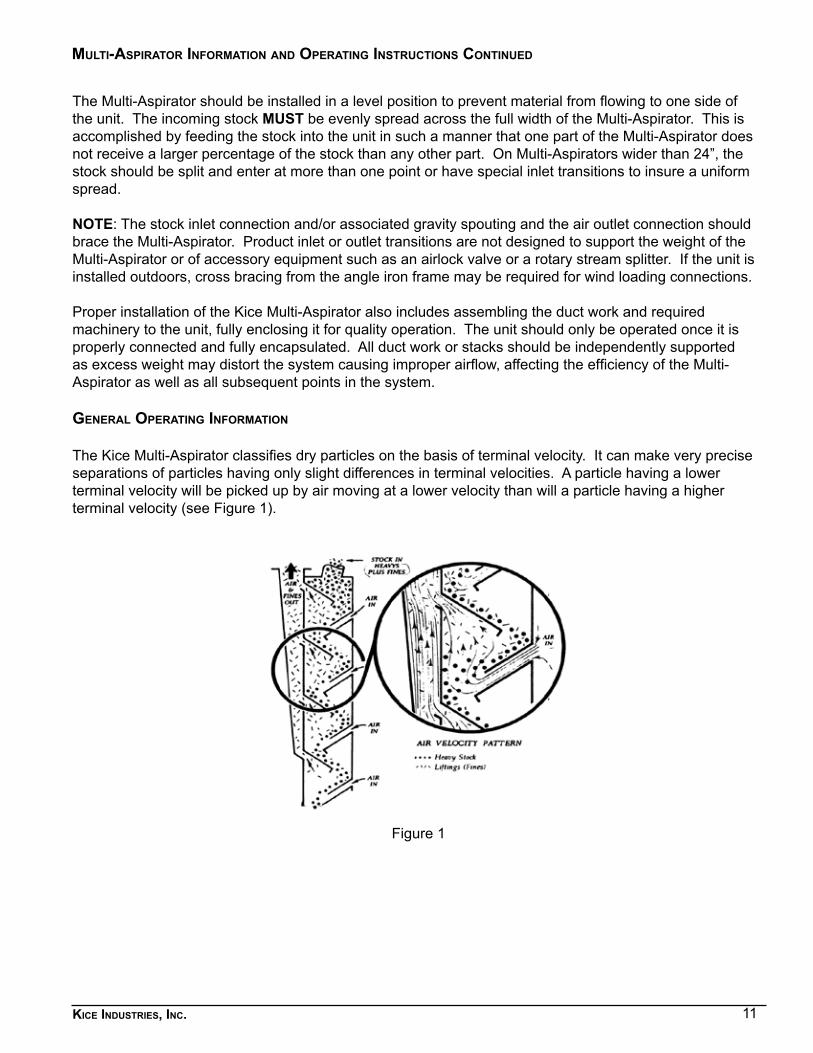
The Kice Multi-Aspirator classifies dry particles on the basis of terminal velocity. It can make very precise separations of particles having only slight differences in terminal velocities. A particle having a lower terminal velocity will be picked up by air moving at a lower velocity than will a particle having a higher terminal velocity (see Figure 1).
Figure 1
12Kice industries, inc.
multi-aspirator information and operatinG instructions continued
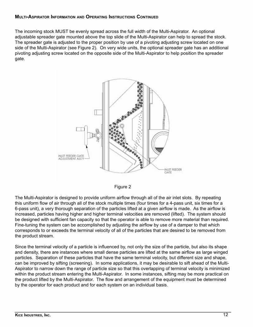
The incoming stock MUST be evenly spread across the full width of the Multi-Aspirator. An optional adjustable spreader gate mounted above the top slide of the Multi-Aspirator can help to spread the stock. The spreader gate is adjusted to the proper position by use of a pivoting adjusting screw located on one side of the Multi-Aspirator (see Figure 2). On very wide units, the optional spreader gate has an additional pivoting adjusting screw located on the opposite side of the Multi-Aspirator to help position the spreader gate.
Figure 2
The Multi-Aspirator is designed to provide uniform airflow through all of the air inlet slots. By repeating this uniform flow of air through all of the stock multiple times (four times for a 4-pass unit, six times for a 6-pass unit), a very thorough separation of the particles lifted at a given airflow is made. As the airflow is increased, particles having higher and higher terminal velocities are removed (lifted). The system should be designed with sufficient fan capacity so that the operator is able to remove more material than required. Fine-tuning the system can be accomplished by adjusting the airflow by use of a damper to that which corresponds to or exceeds the terminal velocity of all of the particles that are desired to be removed from the product stream. Since the terminal velocity of a particle is influenced by, not only the size of the particle, but also its shape and density, there are instances where small dense particles are lifted at the same airflow as large winged particles. Separation of these particles that have the same terminal velocity, but different size and shape, can be improved by sifting (screening). In some applications, it may be desirable to sift ahead of the Multi-Aspirator to narrow down the range of particle size so that this overlapping of terminal velocity is minimized within the product stream entering the Multi-Aspirator. In some instances, sifting may be more practical on the product lifted by the Multi-Aspirator. The flow and arrangement of the equipment must be determined by the operator for each product and for each system on an individual basis.
13Kice industries, inc.
multi-aspirator information and operatinG instructions continued
air Volume
The air volume required for the Multi-Aspirator for a specific material is determined by testing or experience, and is engineered into the system by the designer. After installation, the air volume is fine tuned by observing the material as the air volume is varied by adjusting the damper provided with the fan. The pressure differential across the Kice Multi-Aspirator is quite low – very close to 1” w.c. in most cases and no higher than 3” w.c. when filters are installed on the air inlets.
4. start-uP Procedure
1. Insure that all personnel are clear of any moving pieces of equipment.2. Start the motors on the Multi-Aspirator accessory equipment, such as fans, filters and airlock valves. 3. Completely open the spreader gate, if provided, located above the top slide of the Multi-Aspirator.4. Start any conveying equipment mounted beneath the discharge of the Multi-Aspirator.5. Start the material feeding into the system.6. Adjust the spreader gate, if provided, to insure uniform flow of incoming product across the full width
of the Multi-Aspirator.7. Begin opening the fan damper until excessive material (that has a higher terminal velocity than the
material slated to be removed) is detected in the liftings stream. The determination of what material is to be removed will be made by the system operator.
8. Slightly decrease the airflow by slowly closing the fan damper and lock the damper in place at the optimum setting.
5. maIntenance
There are no moving parts in the Kice Multi-Aspirator to wear out or malfunction, so no lubrication or periodic servicing is required. As the stock cascades down from one slide to another, it drops onto other stock that absorbs the impact, thereby reducing slide wear. Abrasive stock entering the top of the Multi-Aspirator should enter via a deadfall box so that the speed of the incoming stock is reduced and the impact at this point is absorbed, reducing wear. Experience indicates that several years of continuous duty on granular and moderately abrasive material will not wear out the slides or the vertical, tapered air outlet plenum. When wear does occur, it is easy to install a wear plate over the portion of the slide that exhibits erosion. Wear plate installation is facilitated by the fact that all the slides on the air inlet side of the Multi-Aspirator are removable. Elbows, fans and separators in the system are subject to the normal wear expected in any system handling comparable stocks, so equipment must be examined regularly for signs of wear and damage. The Multi-Aspirator has a built-in resistance to wear because the stock is unable to gain momentum within the unit and impact on the internal surfaces. The operator should occasionally look into the unit to see that the stock is spread properly, and should examine the liftings to see that the desired product is being removed. However, there are no close tolerance points that are likely to become blocked and upset the performance of the unit. Keep case exterior and cover clean. Painted surfaces must be cleaned by means of vacuuming and with an anti-static cloth. If heavy machine components must be dismantled to carry out service and maintenance activities, suitable lifting equipment must be used. Use the proper hardware torque values listed at the end of this manual for all maintenance and installation activity.
The optional adjustable spreader gate is mounted between two external flange bearings for ease in positioning the gate. A lever is mounted externally and adjusted by screwing the adjusting arm in and out with a manually operated crank. The bearings and the adjusting screw with the associated pivot will need to be lubricated every 90 to 120 days.
14Kice industries, inc.
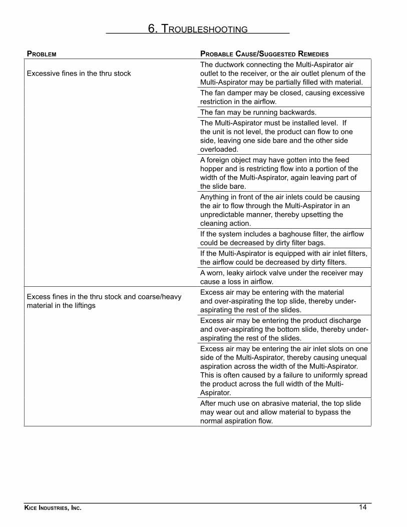
6. troubleshootInG
problem probable cause/suGGested remedies
Excessive fines in the thru stockThe ductwork connecting the Multi-Aspirator air outlet to the receiver, or the air outlet plenum of the Multi-Aspirator may be partially filled with material.The fan damper may be closed, causing excessive restriction in the airflow.The fan may be running backwards.The Multi-Aspirator must be installed level. If the unit is not level, the product can flow to one side, leaving one side bare and the other side overloaded.A foreign object may have gotten into the feed hopper and is restricting flow into a portion of the width of the Multi-Aspirator, again leaving part of the slide bare.Anything in front of the air inlets could be causing the air to flow through the Multi-Aspirator in an unpredictable manner, thereby upsetting the cleaning action.If the system includes a baghouse filter, the airflow could be decreased by dirty filter bags.If the Multi-Aspirator is equipped with air inlet filters, the airflow could be decreased by dirty filters.A worn, leaky airlock valve under the receiver may cause a loss in airflow.
Excess fines in the thru stock and coarse/heavy material in the liftings
Excess air may be entering with the material and over-aspirating the top slide, thereby under-aspirating the rest of the slides.Excess air may be entering the product discharge and over-aspirating the bottom slide, thereby under-aspirating the rest of the slides.Excess air may be entering the air inlet slots on one side of the Multi-Aspirator, thereby causing unequal aspiration across the width of the Multi-Aspirator. This is often caused by a failure to uniformly spread the product across the full width of the Multi-Aspirator.After much use on abrasive material, the top slide may wear out and allow material to bypass the normal aspiration flow.
15Kice industries, inc.
7. sPecIal ateX InformatIon
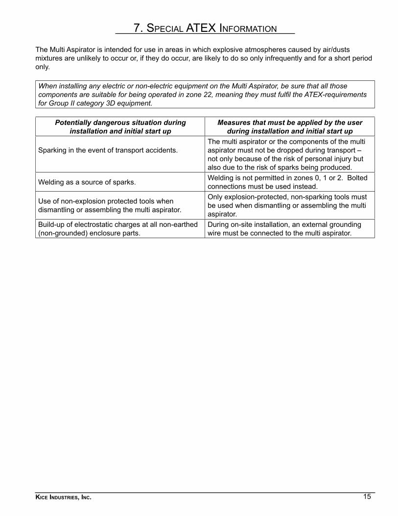
The Multi Aspirator is intended for use in areas in which explosive atmospheres caused by air/dusts mixtures are unlikely to occur or, if they do occur, are likely to do so only infrequently and for a short period only.
When installing any electric or non-electric equipment on the Multi Aspirator, be sure that all those components are suitable for being operated in zone 22, meaning they must fulfil the ATEX-requirements for Group II category 3D equipment.
Potentially dangerous situation during installation and initial start up
Measures that must be applied by the user during installation and initial start up
Sparking in the event of transport accidents.The multi aspirator or the components of the multi aspirator must not be dropped during transport – not only because of the risk of personal injury but also due to the risk of sparks being produced.
Welding as a source of sparks. Welding is not permitted in zones 0, 1 or 2. Bolted connections must be used instead.
Use of non-explosion protected tools when dismantling or assembling the multi aspirator.
Only explosion-protected, non-sparking tools must be used when dismantling or assembling the multi aspirator.
Build-up of electrostatic charges at all non-earthed (non-grounded) enclosure parts.
During on-site installation, an external grounding wire must be connected to the multi aspirator.
16Kice industries, inc.
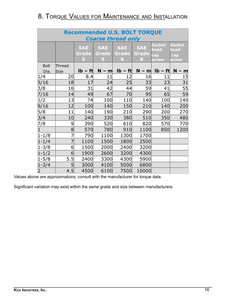
8. torque Values for maIntenance and InstallatIon
Recommended U.S. BOLT TORQUECoarse thread only
SAE Grade
5
SAE Grade
5
SAE Grade
8
SAE Grade
8
Socket head
Socket head
cap screw
cap screw
Bolt Threadlb – ft N – m lb – ft N – m lb – ft N – m Dia. Size
1/4 20 8.4 11 12 16 11 155/16 18 17 24 25 33 23 313/8 16 31 42 44 59 41 557/16 14 49 67 70 95 65 591/2 13 74 100 110 140 100 1409/16 12 100 140 150 210 140 2005/8 11 140 190 210 290 200 2703/4 10 240 330 380 510 350 4807/8 9 390 520 610 820 570 7701 8 570 780 910 1100 850 12001-1/8 7 790 1100 1300 1700 1-1/4 7 1100 1500 1800 2500 1-3/8 6 1500 2000 2400 3200 1-1/2 6 1900 2600 3200 4300 1-5/8 5.5 2400 3300 4300 5900 1-3/4 5 3000 4100 5000 6800 2 4.5 4500 6100 7500 10000
Values above are approximations; consult with the manufacturer for torque data.
Significant variation may exist within the same grade and size between manufacturers.
17Kice industries, inc.
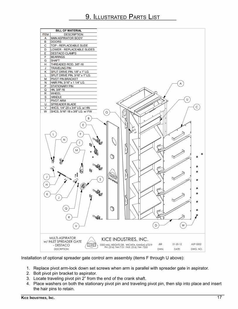
9. Illustrated Parts lIst
Installation of optional spreader gate control arm assembly (items F through U above):
1. Replace pivot arm-lock down set screws when arm is parallel with spreader gate in aspirator.2. Bolt pivot pin bracket to aspirator.3. Locate traveling pivot pin 2” from the end of the crank shaft.4. Place washers on both the stationary pivot pin and traveling pivot pin, then slip into place and insert
the hair pins to retain.
C
A
K
R
G
H
J
Q
M
N
L
E
B
F
T
J
D W
S
U
V
DWG. NO.
KICE INDUSTRIES, INC.
DATE:DWN:
5500 MILL HEIGHTS DR. WICHITA, KANSAS 67219PH: (316) 744-7151 FAX: (316) 744- 7355
01-20-12JBR ASP-5002
DESCRIPTION:
MULTI-ASPIRATORw/ INLET SPREADER GATE
- DESTACO
18Kice industries, inc.
10. oPeratIon of 6dt8 lab and 6dt8 ProductIon unIts
The Kice 6DT4 and 6DT8 Multi-Aspirators work on the same basic principle as the full size “E” Series and “F” Series Kice Multi-Aspirators, classifying material on the basis of the terminal velocity of the particles (see General Operating Information in this manual).
On the 6DT4 and the 6DT8 Multi-Aspirators, the airflow is adjusted utilizing the damper located on the air exhaust of the CE-15 cyclone with the integral ¾ hp fan. In order to lift additional (heavier) particles, the airflow must be increased by opening the damper (resulting in the display of a larger number on the counter). Once the proper air setting is determined for your operation, the product should be introduced into the stock inlet of the Multi-Aspirator in one of the three following ways:
1. 6DT4 and 6DT8-2 – Product is fed by gravity into an open feed hopper. The discharge of the feed hopper is equipped with an adjustable slide gate to regulate product flow.
2. 6DT8-3 – Product is conveyed by a positive pressure conveying system to a cyclone collector and an airlock valve mounted above the Multi-Aspirator stock inlet.
3. 6DT8-4 and 6DT8-5 – Product is conveyed by a Kice supplied vacuum conveying system to a cyclone collector and an airlock valve mounted above the Multi-Aspirator stock inlet.
With the fan turned on, the main air damper should be slowly opened to the proper setting. The proper setting is determined as previously outlined in this manual. The spring-loaded flap or the container to receive the fines below the CE-15 cyclone collector must be in place and the customer’s clean product container should be beneath the Multi-Aspirator stock outlet. The product is then introduced into the system and allowed to flow through the Multi-Aspirator. On the 6DT4 unit, there is a slide gate included with the main damper control. This slide gate is closed to stop the airflow while the fan motor is still running. After the air has stopped flowing, the lifted particles can then be removed by pushing down on the spring-loaded flap located on the stock outlet of the CE-15 cyclone.
After the product has passed through the 6DT8-2, 3 and 4 units, the motor(s) should be stopped. After the air has stopped flowing, the lifted particles collected in the airtight container and the heavy material can then be removed and inspected.
The 6DT8-5 unit is designed to be a continuous operating model. The material is removed from the stock outlet of the Multi-Aspirator and the stock outlet of the cyclone receiver continuously and spouted to the proper destination.
19Kice industries, inc.
11. addItIonal equIPment from KIce IndustrIes, Inc.
centrifuGal fans - fans for eVery industrial needKice fans are durable – built to run around the clock and the calendar, consistently delivering high performance under tough conditions. Four series of versatile workhorse fans are available, including fans and pressure vacuum service operating at both normal and high-pressure differentials.
baGhouse filters - full line of filters/collectors for indoor or outdoor use Five series of high-ratio filters cover most every type of application. They are available in round, square and modular design for capacity, in a large range of sizes. Kice offers an unexcelled selection of filtering materials.
positiVe displacement bloWers - air poWered units for pneumatic conVeyinG systemsKice manufactures a quality line of positive displacement air pump power units. They utilize either positive or negative air pressure to convey materials through a pneumatic system. Pressures, motor sizes and options are matched to your system requirements. A full range of Kice fabricated accessories is available.
multi-aspirators - coVers Wide ranGe of industrial applicationsKice has developed a line of aspirators for use in the feed and grain, plastics powder/bulk solids industries in a wide range of sizes and capacities. Models include the Multi-Aspirator, the Portable Aspirator and the Mini-Aspirator. Applications include cleaning, testing, separation, and sizing.
dust duct - ductWorK and fittinG standardsSystem of pre-engineered piping standards developed especially for air pollution and dust control. Catalog numbering system simplifies design and ordering. Equipment is of solid, sanitary construction, with a smooth aerodynamic design.
rotary airlocKs - World’s most complete line of rotary airlocKsKice builds nearly 100 basic types of airlocks, with thousands of variations available to fit most any pneumatic conveying requirement. Special designs are available for handling difficult materials, high temperatures and high positive and negative pressures. A wide range of capacities is available in both drop-thru and injector series.
20Kice industries, inc.PDB-3-8/12© 2013 Kice Industries, Inc.
5500 N. Mill Heights Dr.Wichita, KS 67219-2358(P) 316.744.7151(F) [email protected]
kice.com