multi channel av receiver - appliance parts | replacement …€¦ · · 2008-04-23o n"_...
TRANSCRIPT

O N"_ 3-284-o83-11./
Multi ChannelReceiver
AV
Operating Instructions
STR-DG520
©2008 Sony Corporation

Owner's RecordThe model :rod serial nunfl_ers are located on the rear
of the unit. Record the serial number in the space
provided below. Rel'cr to them whenever you call
upon your Sony dealer regarding this product.
Model No.
Serial No.
To reduce the risk of fire or electric
shock, do not expose this apparatus torain or moisture.
To prevent fire, do not cover the ventilation of the
apl):u'atus with newspapers, table-cloths, curtains.
etc. And don't place lighted candles on the
apparatus.
To prevent fire or shock hazard, do not place objects
filled with liquids, such as vases, on the apparatus.
Do not install the appliance in a confined space, suchas a bookcase or built-in cabinet.
lnslall this system so that Ilae power cord can be
unplugged from the wall socket immediately in the
eveul (71'trouble.
Batteries or batteries installed apparalus shall not be
exposed to excessive heat such as sunshine, fire ortile like.
For customers in the UnitedStates
This symbol is intended to alert the
user to the presence of uuinsulated
"dangerous voltage" within the
product's enclosure that may be of
sufficient magnitude to constitute a
risk of electric shock to persons.
This symbol is inleuded to alerl file
user to tile presence (71'imperlant
operaling and/71ah/leuauce
(servicing) inslruclions ill the
literature accompanying tile
appliance.
WARNINGThis equipment has been tested :rod lkmnd to comply
with the limits for a (!lass B digital device, pursuantto Part 15 of the FCC Rules. These limits are
designed to provide reasonable protection againstharmful interference in a residential installaliou.
This equipment generates, uses. and can radiate
radio frequency energy and. if not installed and used
in accordance with the instructions, may causeharmful interference to radio communications.
However. there is no guarantee that interference will
not occur in a particular installation. If this
equipment does cause harmful interference to radio
or television reception, which can be determined by
turning the equipment off and on. the user is
encouraged to try to correct the interference by one
or more of the following measures:
Reorient or relocate the receiving antenna.
Increase the separation between the equipmentIlit(]receiver.
Connect the equipment into an outlet on a circuitdifferent from that to which the receiver is
connected.
Consult the dealer or an experienced radio/TV
technician for help.
CAUTIONYou are cautioned that any changes or modification
not expressly approved in this manual could void
your authority to operate this equipment.
Note to CATV system installer:This reminder is provided to c:dl CATV s_stemiustaller's attention to Article 820-40 of the NEC
that provides guidelines for proper grouudi ug and. in
particular, specifies that the cable ground shall be
connected to the grounding system of the building,
as close to the point of cable entry as practical.
2u$

About This Manual
• Tile instructions in this manual are fur mudel
STR-DG520. Check your model number by
louking at the lower right corner of the front paneh
In this mauuah models of area code U is used for
illustratiun purposes unless stated otherwise. Any
difference in operation is clearly indicated in the
text. for example. "Models of area code U only".
• The instructions in this manual describe the
controls on the supplied remute. You can also use
the controls on the receiver if they have the same
or simi]ar uameg as thuse uu the remote.
About area codes
The :wea cude of the receiver you purchased is
shown uu the lower right portiuu of the rear panelsee the illustration below).
Area code
Any differences in operatiuu, accurding to the area
code. are clearly indicated in the text. for example,
"Models of area code AA only".
This receiver incurporates Dolby : Digital and Pru
Logic Surruund aud the DTS:: Digital Surround
System.
: Manufactured under license from DolbyLaboraturies.
Dulby, Pro Logic. and the double-D symbol are
trademarks of Dolby Laboratories.Manufactured under license under U.S. Patent
#'s: 5.451.942: 5.956.674: 5.974.380: 5.978.762:
6.487.535 & other U.S. and wurldwide patents
issued & pending. DTS and DTS Digital
Surround are registered trademarks and the DTS
lugos and Symbol are trademarks of DTS. Inc.
Q 1996-2(I(17 DTS. Inc. All Rights Reserved.
This receiver incorporates High-Definition
Multimedia Interface/HDMI TM) technology.
HDMI. the HDMI logo and High-Definition
Multimedia Interface are trademarks ur registered
trademarks of HDMI Licensing LLC.
3 US

Tableof Contents
Getting StartedDescription and location of parts ................... 5
1: Installing speakers ................................... 13
2: Connecting speakers ................................ 14
3a: Connecting the audio components ......... 15
3b: Connecting the video components ........ 16
4: Connecting the antennas (aerials) ............ 24
5: Preparing the receiver and the remote .....25
6: Adjusting the speaker levels and
balance (TEST TONE) ........................... 26
PlaybackSelecting a component ................................. 28
Listening/Watching. a component . .............. . 29
Amplifier OperationsNavigating through menus ........................... 31
Adjusting the level (LEVEL menu) ............. 34
Adjusting the tone (TONE menn) ............... 35
Settings for the surround sound
(SUR menu) ............................................ 35
Settings for the tuner (TUNER menu) ......... 36
Settings for the audio (AUDIO menu) ......... 36
Settings for the system (SYSTEM menu) ...37
Tuner OperationsListening to FM/AM radio .......................... 4(,
Presetting radio stations .............................. 47
Other Operations
Switching between digital and analog andio
(INPUT MODE) .................................... 50
Enjoying the DIGITAL MEDIA PORT
(DMPORT) ............................................ 50
Naming inputs ............................................. 52
Changing the display .................................. 53
Using the Sleep Timer ................................ 53
Recording using the receiver ....................... 54
Using the RemoteChanging button assignments ..................... 54
Additional Information
Glossary ...................................................... 55
Precautions .................................................. 57
Troubleshooting .......................................... 58
Specifications .............................................. 61
Index ........................................................... 63
Enjoying Surround SoundEnjoying Dolby Digital and DTS Surround
sound (AUTO FORMAT DIRECT) ....... 40
Selecting a pre-programmed sound field.....42
Using only the front speakers
(2CH STEREO) ...................................... 44
Listening to the sound without any
adjustment (ANALOG DIRECT) ........... 45
Resetting sound fields to the initial
settings .................................................... 45
4 Us

O
Descriptionandlocationof parts g.
Q.
Name Fu nction
[] I/(_ Press to turn the receiver on(on/standby) or off (page 25.29. 30. 45.
62).
[] SPEAKERS Press to turn the speaker(ON/OFF) system on or off (page 14).
[] Display The current status of tileselected compouent or a listof selectable items appears
here (page 7).
[] Remote Receives signals from remotesensor comm:mder.
[] DISPLAY Press to select informationdisplayed on the display
(page 53).
[] INPUT MODE Press to select the input mode
wheu the same componentsare connected to both digitaland analog .jacks (page 50).
Name Function
[] MASTER Turn to adjust the volumeVOLUME level of all speakers at the
same time (page 27.28.29.30).
[] MUTING Press to turn off the soundtemporarily.
Press MUTING again torestore the sound (page 28).
[] ANALOG Press to listen to high qu:dity
DIRECT analog sound (page 45).
[] INPUT Turn to select the input
SELECTOR source to play back (page 28.29. 30. 45.46. 48.49. 50. 52.
54).
[] 2CH Press to select a sound Field
A.F.D. (page 40).
MOVIE
MUSIC
continued_5us

Name Function[] MEMORY/ Press to opernte the tuner
ENTER (FM/AM) (page 46).
TUNINGMODE
TUNING +/-
[] PHONES jack Connects to headphones
(page 58).
6 US
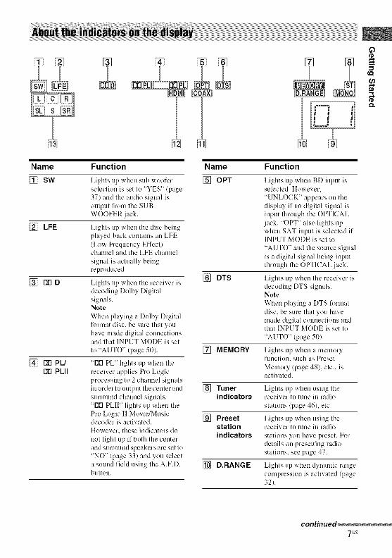
Name Fu nction Name Fu nction
[] SW Lights up when sub woofer [] OPTselection is set to "YES" (page37) and the audio signal isoutput from the SUBWOOFER .jack.
[] LFE Lights up when the disc beingplayed back contains an LFE/Low Frequency Effect)channel and the LFE channel
signal is actually beingreproduced.
[] DTS[] FIN D Lights up when the receiver is
decoding Dolby Digitalsignals.NoteWhen playing a Dolby Digitalformat disc. be sure that youhave made digital connectionsand that INPUT MODE is set
to "AUTO" (page 50).
[] rlrl PL/rlrl PLII
"Dr1 PL" lights up when thereceiver applies Pro Logicprocessing to 2 channel signalsin order to output the center andsurround channel signals."DFI PLIF' lights tip when thePro Logic I1 Movie/Musicdecoder is activated.However. these indicators do
not light up if both the centerand surround speakers are set to"NO" (page 33) and you selecta sound field using the A.F.D.button.
Lights tip when BD input isselected. However.
"UNLOCK" appears on thedisplay if no digital signal isinput through the OPTICALjack. "OPT" also lights upwhen SAT input is selected ifINPUT MODE is set to
"AUTO" and the source signalis a digital signal being inputthrough the OPTICAL .jack.
Lights tip when the receiver isdecoding DTS signals.NoteWhen playing a DTS l\wmatdisc. be sure that you havemade digital connections atKlthat INPUT MODE is set to
"AUTO" (page 50).
[] MEMORY Lights up when a memoryfunction, such as Preset
Memory (page 48), etc.. isactivated.
[] Tuner Lights up when using theindicators receiver to tune in radio
stations (page 46), etc.
[] Preset Lights tip when using thestation receiver to tune in radio
indicators stations you have preset. Fordetails on presetting radiostations, see page 47.
[] D,RANGE Lights up when dynamic rangecompression is activated (page32).
continued_7us

Name Fu nction
[] COAX Lights up 'ahen DVD input isselected. However,
"UNLOCK" appears on tiledisplay if no digital signal isinput through tile COAXIALjack.
[] HDMI Lights up when tile receiver
recognizes a conlponent
connected via a HDMI IN jack(page 171.
[] Playback Tile letters (L, C, R, etc.)channel indicale the channels beingindicators played back. The boxes around
the letters vary to show how thereceiver downmixes the source
sound (based on the speakersettings).
k Front Left
R Front RightC Center (monaural)SL Surround Left
SR Surround RightS Surround (monaural or the
S/lrrO/lIl(] componelltS obtained
by Pro Logic processing)Exalnple:Recording format (Front/Surround): 3/2. I
Output channel: Whensurrouod speakers are set to"NO" (page 33)Sound Field: A.F.D. AUTO
$L SR
8us

D
o.
[] DIGITAL INPUT/OUTPUT section
D OPTICAL Connects Io a DVDIN jacks player, etc. The
COAXIAL jack
O OAXIAL IN provides a belierjack sound quality (page17, 20, 22).
HDMI IN/ Connects to a DVD
OUT jacks: player or a Blu-ray
disc player. Tile
image and tile
sound are output to
aTV (page 17).
[] COMPONENT VIDEO INPUT/OUTPUT section
COMPONENT Connects to a DVD
0 Gyr)een VIDEO player. TV. or aINPUT/ satellite tuner. Yeu
O Blue OUTPUT can enjoy high(PB/CB) jacks' quality image (page
O ed 19.20. 22).(PR/CR)
[] SPEAKERS section
Collllects to
speakers/page 14).
+
[] VIDEO/AUDIO INPUT/OUTPUTsection
O AUDIO IN/ Connects to videoWhite (L) OUT jacks and audio jacks eraVCR. a DVD
O Red (R) (pageplayer, etc.
19 23).
VIDEO IN/Yellow OUT jacks:
[] AUDIO INPUT section
AUDIO IN Connects tea SuperWhite (k) jacks Audie CD player,
CD player, etc.
ORed (R) (page 15).
O AUDIO OUT Connects to a subBlack jack woofer (page 14).
contmued_gus

[] ANTENNA section
FM (-!onnects Io tile EM
Q ANTENNA wire anlelma
.jack (aerial) suppliedwith this receiver
(p_ge 24).
AM Connects to tile AM
ANTENNA loop antennaterminals (aerial) supplied
with this receiver
(page 24).
[] DMPORT
DMPORT Connects to a
.jack DIGITAL MEDIAPORT adapter(page 51 ).
: You can watch the selected input image when you
connect the HDMI OUT or MONITOR OUT jack
to a TV or prqjector (page 17, 19).
You can use the supplied remote to operate thereceiver and to control the Sony audio/videocomponents that the remote is assigned tooperate (page 54).
RM-AAU020
lOUS

Name Function
[] TV I/(_ Press TV I1_ and TV/_) at
(on/standby) the same time to turn the TVon or off.
AV I/(D Press to turn on or off the
(on/standby) Sonyaudio/videocomponentsthat the remote is assigned tooperate (page 54).If you press I1@ ([_/at thesame time. it will turn off thereceiver and other
components (SYSTEMSTANDBY).NoteThe fum.'tion of the AV I/(_)
switch changes automaticallyeach time vou press the inputbull(ms ([_).
[] I/(D Press to turn the receiver on or
(on/standby) off.To [urll oIT all celilponenls,
press I1(_)and AV I1(_)/[_) atthe same time (SYSTEM
STANDBY).
[] Input buttons Press one of the buttons to
select the component youw:mt to use. When you pressany of the input buttons, thereceiver turns on. The buttons
are factory assigned to controlSony components.You can change the buttonassigmnents following thesteps in "Changing buttonassignments" on page 54.
[] 2CH Press to select a sound field.
A.F.D.
MOVIE
MUSIC
[] DVD/BD Press to display the menu of
MENU the DVD or Blu-ray disc onthe TV screen. Then. use 4". _.
*..*. and (_) ([_/to performmenu operations.
[] D.SKIP Press to skip a disc whenusing a multi-disc changer.
[] D.TUNING Press to enter direct tuningmode.
Name
[] AMP MENU
[] MEMORY
ENTER
[] MUTING
[] TV VOL+a)/_
MASTERVOL +a)/_
REPLAY *-./ADVANCE .'-_
_I_I/IIH_ b)
[2>-a)b)
II b)
Function
Press to display the menu ofthe receiver. Then. use 4". _.*. * and (_) ([]) to perform
menu operations.
Press to store a station.
Press to enter the value after
selecting a chmmel, disc ortrack using the numericbuttons of the TV. VCR orsatellite tuner.
Press to turn off the sound
temporarily.Press MUTING again torestore the gOllnd.Press MUTING and TV ([])at the same time to activate
the TV's muting function.
Press TV VOL +M and TV/[]) at the same time to adjustthe TV volume level.
Press to a;[just the volumelevel of all speakers at thesame time.
Press to skip a track of the CDplayer, DVD player or Blu-ray disc player.
Press to replay the previousscene or fast forward thecurrent scene of the VCR.
DVD player or Blu-ray discplayer.
Press tosearch tracks in the forward/
reverse direction of the
DVD player.start fast forward/rewind of
the VCR. CD player or Bit>ray disc player.
Press to start playback of theVCR. CD player, DVD playeror Blu-ray disc player.
Press to pause playback orrecording of the VCR. CDplayer, DVD player or Blu-ray disc player./Also startsrecording with components inrecording standby.)
,,.,I(.Q
Q.
continued_11us

Name Function
I b) Press to stop playback of tileVCR, CD player, DVD playeror Blu-ray disc player.
FM MODE Press to select tile FM
ulouaura] or stereo reception.
TV CH +/- Press TV CH +/ aud TV ([_})at the same time to select
preset TV channels.
PRESET +/- Press to select
preset stations.preset channels of the VCRor satellite tuner.
TUNING +/- Press to scan a station.
[] TV Press TV and tile butlou yOUwant at the same time toactivate the buttons with
orange printing.
[] MENU/HOME Press to display the menu of
the VCR, DVD player,satellite tuner or Blu-ray discplayer on the TV screen.Press MENU/HOME and TV([]) at tile same time to
display the TV's menu.Then, use t, !, _, ,*,and @([]) IO perfornl u/euu
operations.
[] RETURN/EXIT
Press to
return to tile previous menu.exit tile menu while tile
menu or on-screen guide of
the VCR, DVD player,
satellite tuner or Blu-ray disc
player is displayed on tileTV screen.
Press RETURN/EXIT _ mid
TV ([]) at tile same time to
return to tile previous menu orexit the TV's menu while the
menu is displayed on the TVscreen.
Name Function
[] DISPLAY
After pressing DVD/BDMENU ([_), AMP MENIJ/[_) or MENU/HOME/[]),
press t, !, ._,or ,*,to select thesettings. Then. press (_) toenter the selection if you havepressed DVD/BD MENU orMENU/HOME previously.Press (_) also Ill enter tileselection of the receiver.VCR. satellite tuner. CD
player, DVD player or Blu-ray disc player.
Press to select infornmtion
displayed on the TV screen ofthe VCR, satellite tuner, CD
player, DVD player or Blu-ray disc player.Press DISPLAY aud TV ([])
at the same time to displayTV's inlbrmation on tile TVscreen.
[] TOOLS/OPTIONS
] ./..
Press to display and select theoptions of tile DVD player orBlu-ray disc player.Press TOOLS/OPTIONS andTV ([]) at tile same lime to
display options applicable totile Sony TV.
Press to select the channel
entry mode, either (}lie or twodigit of the VCR.Press -/-- and TV ([]) al filesame time to select the
channel entry mode, eitherone or two digits of the TV.
>10/- Press to selecttrack mnubers over lO of tileVCR, satellite tuner or CD
player.channel nmubers of tile
Digital CATV terminal.
CLEAR Press to clear a mistake when
you press the incorrectnumeric button.
12us

Name Function
[] Numeric Press to
buttons preset/tune to [)reset(number 5a)) stations.
select track tmmbers of the
CD player, DVD player or
Blu-ray disc player. Press O/I 0 to select track number 10.select channel numbers of
the VCR or satellite tuner.
Press the numeric buttons and
TV ([_/at the same time toselect the TV channels.
[] TV INPUT Press TV INPUT and TV ([_)
at the same time to select the
input signal (TV input or
vide() input).
SLEEP Press to activate the SleepTimer function and the
duration which the receiver
turns off automatically.
:'/The number 5. MASTER VOL +. TV VOL +. :rod
E::>- buttons have tactile dots. Use the tactile dots
:is references when operating the receiver.blThis button is also available for DIGITAL
MEDIA PORT adapter operation. For details on
the function of the button, see the operating
instructions supplied with the DIGITAL MEDIA
PORT adapter.
Notes
• Some functions exph,ined in this section may not
work depending on the modeh
• The above explanation is intended to serve as an
example only. Therefore. depending on the
component, the above operation may not be
possible or may operate differently than described.
1"InstallingspeakersThis receiver allows you to use a 5.1 channelsystem (5 speakers and one sub woofer).To tully enjoy theater-like multi channelsurround sound requires five speakers (twofront speakers, a center speaker, and twosurround speakers) and a sub woofer (5.1channel).
Example of a 5.1 channelspeaker system configuration
I_Front speaker (left)
I_]Front speaker (right)
r_Center speaker
r_Surronnd speaker (left)
rllSurround speaker (right)
rdsub woofer
TipSince the sub woofer does not emil highly
directional signals, you can place it wherever you
want.
o
,,.,I
Q.
13us

2: ConnectingspeakersBet_re connecting cords, make sure to
disconnect the AC power cord (mains lead).
[] [] []
0 0
0
O Monaural audio cord (not supplied)Speaker cords (not supplied)
[]Front speaker (left)
rfflFront speaker (right)
[_Center speaker
ri'lSurround speaker (left)
r_Surround speaker (right)
rtSub woofer '_
: When you connect a sub woofer with an auto
standby function, turn off tile flmction when
watching movies. If the auto standby lhnction is
set to on. it turns to standby mode automatically
based on the level of the input signal to a sub
woofer, then sound may not be output.
Note
You czm turn on or off the speaker s_stem "_ith the
SPEAKERS (ON/OFF) button (page 51.
14us

3a"Connectingthe audiocomponentsBefore cennecling _.'erds, make s/ire t() discel]eect
the AC pewer cord (mains lead).
The following illustration shows how to
connect a Super Audio CD/CD player.
After connecting your Super Audio CD/CD
player, proceed to "3b: Connecting the video
components" (page 16) or "4: Connecting the
antennas (aerials)" (page 24).
if)
Q.
Super Audio CDplayer/CD player
OAudio cord (not supplied)
15us

3b: Connectingthe videocomponents
This section describes how to connect yourvideo components to this receiver. Before youbegin, refer to "Component to be connected"below for the pages which describe how toconnect each component.After connecting all your components,proceed to "4: Connecting the antennas(aerials)" (page 24).
Component to be connected
Component Page
With HDMI.jack 17
TV 19
DVD player/DVD recorder 20
Satellite tuner/Set-top box 22
VCR 23
The image quality depends on the connecting
jack. Refer to the illustration that t_llows.
Select the connection according to the jacks on
your components.
Digital Analog
High quality image
16us

HDMI is the abbreviated name for High-Definition Multimedia Interfuce. It is aninterface which transmits video and audio
signals in digital fornlat.Before connecting cables, make sure todisconnect the AC power cord (mains lead).
if)
I.Q
Q.
DVD player
Audio Audio/videosignals signals
nO O
Blu-ray disc player
Audio I Audio/video
signals
O O
TV, etc.
Audio/video
signals
O Coaxial digital cord (not supplied)Q HDMI cable (not supplied)
"_Vereconimend that you use a Sony HDMI cable.
_Optical digital cord (not supplied)
continued_17us

Notes on HDMI connections• The sound is output from the TV speaker
only when a playback component and this
receiver, as well as this receiver and the TV
are connected via the HDMI jack. To output
the sound from the speakers and to take
advantage of the multi channel surround
sound, be sure to
- connect the digital audio jacks on the
playback component to the receiver.
turn off TV's volume or activate the TV's
muting flmction.
• The nmlti/stereo area audio signals of a
Super Audio CD are not output.
• Vkteo signals input to the HDMI IN jack can
only be output from the HDMI OUT jack.
The input video signals cannot be output
from the VIDEO OUT jacks, or MONITOR
OUT jacks.
• Check the setup of the connected component
if an image is poor or the sound does not
come out of a component connected via the
HDMI cable.
• This receiver may not be able to transfer
video or audio signals with certain types of
components.
• Refer to the operating instructions of each
component connected for details.
Notes
• Be sure to turn on the receiver when the video :rod
audio signals of a playback component are being
output to a TV via the receiver. Unless the power is
turned on, neither video nor audio signals will betransmitted.
• When connecting optical digital cords, insert the
plugs straight in until they click into place.
• Do not bend or tie optical digital cords.
TipAll the digital audio jacks are compatible with
32 kHz. 44.1 kHz. 48 kHz. and 96 kHz sampling
frequencies.
18us

The image from a video component connectedto this receiver can be displayed on a TVscreen.It is not necessary to connect all the cords.Connect audio and video cords according tothe jacks of your components.Bel\_re connecting cords, make sure todisconnect the AC power cord (mains lead).
Note
Be sure to turn oil the receiver when tile video and
audio signals of a playback component are being
output to a TV via tile receiver. Unless tile power is
turned on. neither video nor audio signals will betransmitted.
Tips
• You can watch the selected input image when you
connect the MONITOR OUT or HDMI OUT.jack
to a TV or projector.
• To output the sound of the TV from the speakersconnected to the receiver, be sure to:
connect the audio output jacks of the TV to the
TV AUDIO IN .jacks of the receiver.
turn off TV's vohune or activate the TV's mutingfunction.
D
D.
TV
Audio signals Video signals
il e o IIi o
_Audio cord (not supplied)OVideo cord (not supplied)_Component video cord (not supplied)
1gus

The following illustration shows how to
connect a DVD player/DVD recorder.
It is not necessary to connect all the cords.
Connect audio and video cords according to
the jacks of your components.
Bet_re connecting cords, make sure to
disconnect the AC power cord (mains lead).
Notes
• To input nmlti chmmel digital audio from tile DVD
player, set tile digital audio output setting on tile
DVD player. Refer to the operating instructions
supplied with the DVD player.
• As this receiver does not have analog audio input
jacks for DVD, connect your DVD player to the
DIGITAL COAXIAL DVD IN jack on tile
receiver. To output sound from the front lefl/right
speakers only, press 2CH.
TipAll the digital audio jacks are compatible with
32 kHz, 44.1 kHz, 48 kHz, and 96 kHz sampling
frequencies.
Connecting a DVD player
Audio signals
DVD player
Video signals
O O
OCoaxial digital cord (not supplied)_Video cord (not supplied)l_Component video cord (not supplied)
20us

Connecting a DVD recorder
Video signals
DVD recorder
Audio signals
L
O
(,Q
Q.
OVideo cord (not supplied)OAudio cord (not supplied)
Notes
• Be stlre to ch:li'Jge the factory setting of the VIDEO
input button on the remote se that you can use the
button to control your DVD recorder. For details.
see "Changing button assignments" (page 54).
• You can also rename the VIDEO input so that it
can be displayed on the receiver's display. For
details, see "Naming inputs" (page 52).
21us

.ii
The following illustration shows how to
connect a satellite tnner or a set-top box.
It is not necessary to connect all the cords.
Connect audio and video cords according to
the jacks of your components.
Bet_re connecting cords, make sure to
disconnect the AC power cord (mains lead).
Notes
• When connecting optical digit:d cords, insert tileplugs slraight in until they click into place.
• Do not bend or tie optical digital cords.
TipAll the digital audio jacks are compatible with32 kHz. 44.1 kHz. 48 kHz. and 96 kHz samplingfrequencies.
Satellite tuner/set-top box
Audio signals Video signals
OAudio cord (not supplied)_Optical digital cord (not supplied)OVideo cord (not supplied)_Component video cord (not supplied)
22us

Before connecting cords, make sure to
disconnect the AC power cord (mains lead).
The t_llowing illustration shows how toconnect a component which has analog jackssuch as a VCR, etc.It is not necessary to connect all the cords.Connect audio and video cords according tothe jacks of your components.
Video signals
VIDEO VII
VCR
Audio signals
o
OVideo cord (not supplied)OAudio cord (not supplied)
23 us

4: Connectingthe antennas(aerials)Connect the supplied AM loop antenna(aerial) and FM wire antenna (aerial).
Bet_re connecting the antennas, make sure todisconnect the AC power cord (mains lead).
FM wire antenna (aerial) (supplied)
AM loop antenna (aerial)(supplied)
: The shape of the connector varies depending onthe area cede of this receiver.
Notes
• To prevent noise pickup, keep the AM loopantenna (aerial) away from tile receiver and ether
cenlponents.
• Be sure to fiflly extend the FM wire antenna(aerial).
• After connecting the FM wire antenna (aerial),
keep it as horizontal as pessible.
24us

5: Preparingthereceiverandtheremote
Connect the AC power cord (mains lead) to awall outlet.
Notes
• Bel\_re connecting tile AC po'_ er cord (mains
lead), make sure that the stripped end of the
speaker cords are not toeching each other between
the speaker terminals.
• Connect the AC power cord (mains lead) firmly.
AC power cord (mains lead)
To the wall outlet
Before using the receiver for the first time,m,
initialize the receiver by performing the "
following procedure. This procedure can also
be used to return settings you have made to
their factory defaults. _.Be sure to use the buttons on the receiver t_r
this operation.
1,2
1
2
3
3
Press I/_ to turn off thereceiver.
Hold down I/(_ for 5 seconds.
"PUSH" and "ENTER" appears on thedisplay alternately.
Press MEMORY/ENTER.
After "CLEARING" appears on thedisplay for a while, "CLEARED"
appears.All the settings you have changed oradjusted are reset to the initial settings.
25us

Insert two R6 (size-AA) batteries in the
RM-AAU020 Remote Commander.
Observe the correct polarity when installing
batteries.
Notes
• Do not leave tile remote in an extremely hot or
humid place.
• Do not use a new battery with old ones.
• Do not mix manganese batteries and other kinds ofbatteries.
• Do not expose the remote sensor to direct sunlight
or lighting apparatuses. Doing so may cause amalfunction.
• If you do not intend to use the remote for an
extended period of time. remove the batteries to
avoid possible damage from battery leakage andcorrosioll.
• When you replace the batteries, the remote buttons
may be reset to their factory settings. If this
happens, reassign the buttons again (page 54).
TipUnder normal conditions, the batteries should last
for about 3 months. When the remote no longer
operates the receiver, replace all the batteries withnew ones.
6: Adjustingthe speakerlevelsandbalance(TEST TONE)
You can adjust the speaker levels and balancewhile listening to the test tone from yourlistening position.
TipThe receiver employs a test tone with a frequencycentered at 800 Hz.
Input
2-!MASTER
,4! Press AMP MENU.
"I-LEVEL" appears on the display.
2 Press (_) or, to enter themenu.
3 Press 4,14,repeatedly to select"T. TONE".
4 Press -_ or* to enter theparameter.
26us

5
6
7
Press 4,/,!, repeatedly to select"T. TONE Y".
The test tone is output from each speaker
in sequence as follows:
Front left _ Center _ Front right
Surround right _ Surround left
Sub woofer
Adjust the speaker levels andbalance using the LEVEL menuso that the level of the test tonesounds the same from each
speaker.For details, see "Adjusting the le'_el
(LEVEL menu)" (page 34).
Tips
• To mljust tile level of all speakers at tile same
time, press MASTER VOL +_. You can alsouse MASTER VOLUME on the receiver.
• The adjusted wflue is shown on the display
during a@lstment.
Repeat steps 1 to 5 to select"T. TONE N".
You can also press any input buttons.The test tone turns oft'.
When a test tone is not outputfrom the speakers• The speaker cords may not be connected
securely.
• The speaker cords may have the short-circuit
problem.
Note
Tile test tolle does not "_ork when ANAL()(;
DIRECT is selected.
O
,,.,I
Q.
27us

Selectinga component
MUTING
3
Press the input button to selecta component.You can also use INPUT SELECTOR on
the receiver.
The selected input appears on the display.
Selected input Components that can[Display] be played back
VIDEO VCR. etc.. connected to
[VIDEO] tile VIDEO .jack
BD Blu-ray disc player, etc..[BD] connected to the BD jack
DVD DVD player, etc..[DVD] connected to the DVD
jack
SAT Satellite tuner, etc..
[SAT] connected to the SAT jack
TV TV. etc.. connected to the
[TVI TV .jack
SA-CD/CD Super Audio CD/CD[SA-CD/CD] player, etc.. connected to
the SA-CD/CD jack
TUNER Built-in radio tuner
[FM or AM bandl
DMPORT DIGITALMEDIA PORT
[DMPORT] adapter connected toDM PORT jack
2 Turn on the component andstart playback.
3 Press MASTER VOL +/- to
adjust the volume.You can alsouse MASTER VOLUME onthe receiver.
To activate the muting functionPress MUTING.
The muting function will be canceled when
you do the following.
• Press MUTING again.• Increase the volume.
• Turn offthe receiver.
To avoid damaging yourspeakersBefore you turn off the receiver, be sure to turn
down the volume level.
28us

Listening/Watchinga component
=5
5
3
Notes
• The operatkm is described 1i)1"a
Sony Super Audio CD phlyer.
• Refer to tile operating
instructions supplied with the
Super Audio CD player or CD
player.
Tip
You can select the sound field to
suit the music. Refer to p_ge 40for details.
Recommended sound fields:
Classical: HALL
Jazz: JAZZ
Live concert: CONCERT
1
23
456
Turn on the Super Audio CD player/CDplayer, then place the disc on the tray.
Turn on the receiver.
Press SA-CD/CD.
You can also use INPUT SELECTOR on the receiver to
select "SA-CD/CD".
Play back the disc.
Adjust to a suitable volume.
After you have finished listening to theSuper Audio CD/CD, eject the disc and turnoff the receiver and Super Audio CD player/CD player.
29us

_i_ !III_II!_
Nili!ii!ii!ii!_i:i!i!!Niiiilliii_iiiiiiiiiiiiiiiiiiiiiiii_iiiiiiiiiilN_i_iiiiiiiiiiiiiiiiiiiiiiiiiiiiiiiiiiiiiii!__
Notes
• Refer to the operating
iustructiuus supplied with tile
TV and DVD player or Blu-ray
disc player.
• Check the following if youcmmot listen tu multi channel
sound.
Be sure this receiver is
cuuuected tu the DVD player
or Blu-ray disc player via a
digital connection.
Be sure the digital audio
output uf the DVD player or
Blu-ray disc player is set up
pruperly.
Tips• Select the sound format of the
disc to be played, if necessary.• You can select the sound field to
suit the movie/music. Refer to
page 40 lk_rdetails.Recommended sound fields:
Muvie: C.ST.EX
Music: CONCERT
1
23
4
567
6
3
Turn on the TV and DVD player or Blu-raydisc player.
Turn on the receiver.
Press DVD or BD.You can also use INPUT SELECTOR on this receiver to
select "DVD" or "BD".
Switch the input of the TV so that an imageof the DVD or Blu-ray disc is displayed.
Play back the disc.
Adjust to a suitable volume.
After you have finished watching the DVD orBlu-ray disc, eject the disc and turn off thereceiver, TV and DVD player or Blu-ray discplayer.
30 us

Navigating throughmenus
To return to the previous displayPress I,.
By using the amplifier menus, you can make
various adjustments to customize the receiver.
2-1
To exit the menuPress AMP MENU.
NoteSome paranleters and settings may appear dilnmed
on the display. This means that they are either
unavailable or fixed and unchangeable.
3m,
oI'D
1 Press AMP MENU.
"I-LEVEL" appears on the display.
2 Press 4,1,!,repeatedly to selectthe menu you want.
3 Press @ or* to enter themenu.
4 Press 4,1,!,repeatedly to select
the parameter you want toadjust.
5
6
Press _;) or * to enter theparameter.
Press 4,1,!,repeatedly to selectthe setting you want.
The setting is entered automatically.
31us

The following options are available in eachmenu. For details on navigating through
menus, see page 31.
Menu Parameters
[Display] [Display]
LEVEL Test tone _°IT. TONE]
[I-LEVEL] Front speaker balance _/(page 341 [FRT BALI
Center speaker level[CNT LVL]
Surround left speaker level[SL LVLI
Surround right speaker level[SR LVLI
Sub woofer level
[SW LVL]
Dynamic range conlpressor a)
[D. RANGEI
TONE Front speaker bass level[2-TONEI [BASS LVLI
(page 35)Front speaker treble level[TRE LVL]
SUR Sound field selection a)
[3-SUR] [S.F. SELCT]
(page 35)
Effect level a/[EFFECT] EFCT. MIN. EFCT. STD.EFCT. MAX
TUNER FM slalion receiving mode a) FM AUTO. FM MONO[4-TUNER] [FM MODEl
(page 36)
Naming preset stations a) For details, see "Naming presel
[NAME IN] stations" (page 49).
Settings Initialsetting
T. TONE N. T. TONE Y T. TONE N
BAL. L+I to BAL. L+8. BALANCE. BALANCEBAL. R +1 to BAL. R +8
CNT l0 dB toCNT +10dB CNT 0dB
/ l dB step)
SURL 10dB to SUR L +10dB SUR L0 dB
/ l dB step)
SURR 10dB to SUR R +10dB SUR R 0dB
/ l dB step)
SW 10dBtoSW+10dB SW0dB
/ l dB step)
COMP. OFF. COMP. STD. COMP. OFF
COMP. MAX
BASS 6dBtoBASS+6dB BASS0dB
/ 1 dB step)
TRE 6dB to TRE +6 dB TRE0dB
/ 1 dB step)
For details, see "E_joying Surround A.F.D. AUTOSound" (page 401. for:
VXDEO. BD.
DVD. SAT:2CH ST. for:TV. SA-CD/CD.TUNER.
DMPORT
EFCT. STD
FM AUTO
32us

Menu Parameters Settings Initial[Display] [Display] setting
AUDIO Digital :radio input decoding DE(-'. PCM. DE(-'. AUTO DE(-'. AUTO[5-AUDIO] priority a) [DEC. PRI.]
(page 36)
Digital broadcast language DUAL M/S. DUAL M. D1JAL S. D1JAL Mselection a_[DUAL] DUAL M+S
Synchronizes audio and vide() A.V.SYNC. N. A.V.SYNC. Y A.V.SYNC. Noutput a) [A.V. SYNC.]
Naming inputs a) [NAME IN] For details, see "Naming inputs"
(page 52).
SYSTEM Sub woofer a) YES. NO YES
[6-SYSTEM] [SW SPK]
(page 37)
Front speakers a) SMALL. LARGE LARGE[FRT SPK]
Center speakers a} NO. SMALL. LARGE LARGE[CNT SPK]
Surround speakers a) NO. SMALL. LARGE LARGE[S1JR SPK]
Front speaker distance a) DIST. 3 ft. to DIST. 23 It. DIST. 10 It.
[FRT DIST.] (1 It. step)
Center speaker distance a} DIST. 3 ft. to DIST. 23 It. DIST. 10 It.
[CNT DIST.] (1 It. step)
Surround left speaker distance a) DIST. 3 ft. to DIST. 23 It. DIST. 10 It.
[SL DIST.] (1 It. step)
Surround right speaker DIST. 3 ft. to DIST. 23 It. DIST. 10 It.distance a) (1 It. step)
[SR DIST.]
Surround speaker position a) BEHD/HI. BEHD/LO. SIDE/HI. SIDE/LO
[SUR POS.] SIDE/LO
Speaker crossover frequency a) CRS > 4(}Hz to CRS > 16(}Hz CRS > 100 Hz
[CRS. FREQ]
Brightness of the display a) OC)_dim. 40c)_ dim. 70c)_ dim 0(/_ dim[DIMMER]
a)For details, refer to the page in the parentheses.
3
O
33us

Adjustingthe level(LEVELmenu)
You can use the LEVEL menu to adjust the
balance and level of each speaker. These
settings are applied to all sound fields.
Select "I-LEVEL" in the amplifier menus. For
details on adjusting the parameters, see
"Navigating through menus" (page 31) and
"Overview of the menus" (page 32).
LEVEL menu parameters
• T. TONE (Test tone)Lets you adjust tile speaker le_.els mid bahmce
while listening to the test tone from your
listening position. For details, see
"6: Ac[justing the speaker levels and balance
(TEST TONE)" (page 26).
• FRT BAL (Front speakerbalance)
Lets you adjust tile bahmce between front left
and right speakers.
• CNT LVL (Center speaker level)
• SL LVL (Surround left speakerlevel)
• SR LVL (Surround right speakerlevel)
• SW LVL (Sub woofer level)
• D. RANGE (Dynamic rangecompressor)
Lets you compress the dynamic range of the
sound track. This may be usefid when you
want to watch movies at low volumes late at
night. Dynamic range compression is possible
with Dolby Digital sources only.
• COMR OFF
The dynamic range is not compressed.
• COMR STD
The dynamic range is compressed as
intended by the recording engineer.• COMR MAX
The dynamic range is compressed
dramatically.
ripDynamic range compressor lets you compress the
dynanfic range of the soundtrack based on the
dynanfic range information included in the Dolby
Digital signah
"COMP. STD" is the standard setting, but it only
enacts light compression. Therefore, we recommend
using the "COMP. MAX" setting. This greatly
compresses the dynamic range and lets you view
movies late at night at low vohnnes. Unlike analog
limiters, the levels are predetermined and provide a
very natural compression.
34us

Adjustingthe tone(TONE menu)
You can use the TONE menu to ac[iust the
tonal quality (bass/treble level) of the front
speakers. These settings are applied to allsound fields.
Select "2-TONE" in the amplifier menus. For
details on adjusting the parameters, see
"Navigating through menus" (page 31) and
"Overview of the menus" (page 32).
TONE menu parameters
• BASS LVL (Front speaker basslevel)
• TRE LVL (Front speaker treblelevel)
Settingsfor the surroundsound(SURmenu)
You can use the SUR menu to select the sound
fiekt you want l\_r your listening pleasure.
Select "3-SUR" in the amplifier menus. For
details on adjusting the parameters, see
"Navigating through menus" (page 31) and
"Overview of the menus" (page 32).
SUR menu parameters
• S.F. SELCT (Sound fieldselection)
Lets you select the sound fiekt you want. For
details, see "Enjoying Surround Sound" (page
40).
Note
Tile receiver lets you apply the last selected sound
field to an input whenever it is selected (Sound Field
Link). For example, if you select "HALL" for the
SA-CD/CD input, then change to a different inputand then return to SA-CD/CD, "HALL" will
automatically be applied again.
• EFFECT (Effect level)Lets you adjust the "presence" of the surroundeffect for sound fields selected with theMOVIE or MUSIC buttons and for "HPTHEA" sound field.• EFCT. MIN
The surround effect is minimum.• EFCT. STD
The surround effect is standard.• EFCT. MAX
The surround effect is maximum.
3
O
I'D
,,',I
35us

Settingsfor the tuner(TUNERmenu)
You can use the TUNER menu to set the FM
station receiving mode and to name presetstations.
Select "4-TUNER" in the amplifier menus.
For details on adjusting the parameters, see
"Navigating through menus" (page 31) and
"Overview of the menns" (page 32).
TUNER menu parameters
• FM MODE (FM station receivingmode)
• FM AUTO
This receiver will decode the signal as stereo
signal when the radio station is broadcast instereo.
• FM MONO
This receiver will decode the signal as mono
signal regardless of the broadcast signal.
• NAME IN (Naming presetstations)
Lets you set tile name of preset stations. For
details, see "Naming preset stations" (page
49).
Settingsfor the audio(AUDIO menu)
Yon can use the AUDIO menu to make
settings for the audio to suit your preference.
Select "5-AUDIO" in the amplifier menns. For
details on adjusting the parameters, see
"Navigating through menus" (page 31 ) and
"Overview of the menus" (page 32).
AUDIO menu parameters
• DEC. PRI. (Digital audio inputdecoding priority)
Lets you specify the input mode for the digital
signal input to the DIGITAL IN jacks.• DEC. PCM
PCM signals are given priority (to prevent
interruption when playback starts).
However, when other signals are input, there
may be no sound depending on the format.
In this case, set to "DEC. AUTO".
• DEC. AUTO
Automatically switches the input mode
between DTS, Dolby Digital, or PCM.
Note
When set to "DEC. AUTO" and the sound from the
digital audio jacks (for a CD. etc.) is interrupted
when playback starts, set to "DE(?. PCM'.
36us

• DUAL (Digital broadcastlanguage selection)
Lets you select tile hmguage you want to listen
to during digital broadcast. This feature only
fimctions for Dolby Digital sources.
• DUAL M/S (Main/Sub)
Sound of the main language will be output
through the front left speaker and sound of
the sub language will be output through the
front right speaker simultaneously.
• DUAL M (Main)
Sound of the main language will be output.
• DUAL S (Sub)
Sound of the sub language will be output.
• DUAL M+S (Main + Sub)
Mixed sound of both the main and sub
languages will be output.
• A.V. SYNC. (Synchronizes audioand video output)
• A.V.SYNC. N (No) 0)clay time: 0 ms)
The audio output is not delayed.
• A.V.SYNC. Y (Yes) (Delay time: 60 ms)
The audio output is delayed so that the time
gap between the audio output and visual
display is minimized.
Notes
• This p:wameter is useful wlmn you use a l:wge LCDor plasma TV or a prc_iector.
• This parameter is valid only when you use a soundfield selected with the 2CH or A.F.D. buttons.
• This parameter is not valid when
signals with a sampling frequency of more than
48 kHz is input.ANALOG DIRECT flmction is selected.
• NAME IN (Naming inputs)Lets you set the name of inputs. For details,
see "Naming inputs" (page 52).
Settingsfor thesystem(SYSTEMmenu)
You can use the SYSTEM menu to set the size
and distance of the speakers connected to this
system.
Select "6-SYSTEM" in the amplifier menus.
For details on adjusting the parameters, see
"Navigating through menus" (page 31) and
"Overview of the menus" (page 32).
SYSTEM menu parameters
• SW SPK (Sub woofer)• YES
If you have connected a sub woofer, select"YES".
• NO
If you have not connected a sub woofer,select "NO". This activates the bass
redirection circuitry and outputs the LFE
signals from other speakers.
TipIn order to take full advantage of the Dolby Digital
bass redirection circuitry, we recommend setting the
sub woofcr's cut off frequency as high as possible.
3
O
ID
continued,37us

• FRT SPK (Front speakers)• SMALL
If the sound is distorted, or you feel a lack of
surround effects when using multi channel
surround sound, select "SMALL" to activate
the bass redirection circuitry and outpnt the
front channel bass frequencies t_om the sub
woofer. When the front speakers are set to
"SMALL", the center and surround speakers
are also automatically set to "SMALL"
(unless previously set to "NO").
• LARGE
If yon connect large speakers that will
effectively reproduce bass frequencies,
select "LARGE". Normally, select"LARGE". When the sub woofer is set to
"NO", the front speakers are automatically
set to "LARGE".
• CNT SPK (Center speaker)• NO
If you have not connected a center speaker,
select "NO". The sound of the center
channel will be output from the front
speakers.
• SMALL
If the sound is distorted, or you feel a lack of
surround effects when using multi channel
surround sound, select "SMALL" to activate
the bass redirection circuitry and output the
center channel bass frequencies from the
front speakers (if set to "LARGE") or sub
woofer.
• LARGE
If yon connect a large speaker that will
effectively reproduce bass frequencies,
select "LARGE". Normally, select
"LARGE". However. if the front speakers
are set to "SMALL", you cannot set the
center speaker to "LARGE".
• SUR SPK (Surround speakers)• NO
If you have not connected surronnd
speakers, select "NO".• SMALL
If the sound is distorted, or you feel a lack of
surround effects when using multi channel
surround sound, select "SMALL" to activate
the bass redirection circuitry and output the
surround channel bass t_equencies from the
sub woofer or other "LARGE" speakers.
• LARGE
If you connect large speakers that will
effectively reproduce bass frequencies,
select "LARGE". Normally, select
"LARGE". However, if the front speakers
are set to "SMALL", you cannot set the
surround speakers to "LARGE".
TipThe "LARGE" and "SMALL" settings for each
speaker determine whether the internal sound
processor will cut the bass signal from that channel.When the bass is cut from a channel, file bass
redirection circuitry sends the corresponding bass
frequencies to the sub woofer or other "LARGE"
speakers.However. since bass Sotlnds have a certain amount
of directionality, it is best not to cut them. if
possible. Therelk)re. even when using small
speakers, you can set them to "LARGE" if you want
to output the bass frequencies from thai speaker. On
the ()tiler hand. if you are using a large speaker, but
prefer not to have bass frequencies output from that
speaker, set it to "SMALL".
If the overall sound level is lower than you prefer.
set all speakers to "LARGE". If there is not enough
bass. you can use tile tone to boost tile bass levels.
For details, see page 32.
38 us

• FRT DIST. (Front speakerdistance)
Lets you set tile distance from your listening
position to the front speakers (O). If both
front speakers are not placed an equal distance
from your listening position, set the distance to
the closest speaker.
• CNT DIST. (Center speakerdistance)
Lets you set the distance from your listening
position to the center speaker.
• SL DIST. (Surround left speakerdistance)
• SR DIST. (Surround rightspeaker distance)
Lets you set the distance from your listening
position to the surround speaker.
• SUR POS.(Surround speaker position)
Lets you specify the location of your surround
speakers for proper implementation of the
surround effects in the Cinema Studio EX
modes (page 43). This setup item is not
available when the surround speakers are set to
"NO" (page 33).
O O
ill
....... ,,, iiii!i
• BEHD/HI
Select if the location of your surround
speakers corresponds to sections O and _}.
• BEHD/LO
Select if the location of your snrround
speakers corresponds to sections O and i_.
• SIDE/HI
Select if the location of your surround
speakers corresponds to sections _ and 1_.
• SIDE/LO
Select if the location of your surround
speakers corresponds to sections _ and i_.
3m,
O
o
continued_39us

Tip
Surround speaker position is designed specifically
lk_rimplementation ufthe Cinema Studio EX modes.
For other sound fields, speaker position is not socritical.
Those sound fields were designed under the premise
that the surround speakers would be located behind
the listening position, but presentation remains
fairly consistent even with the surround speakers
positioned at a rather wide angle. However. if the
speakers are pointing toward the listener from the
immediate left and right of the listening position, thesurruuud effects becunm unclear unless set to
"SIDE/LO" or "SIDE/HI".
Nevertheless. each listening enviromnent has many
variables, such as wall reflections, and you may
obtain better results using "BEHD/HF' if your
speakers are located high above the listening
position, even if they are located to the immediate
left and right.
Therefore. although it may result in a setting
contrary to the above explanation, we recolunmnd
that you playback multi chamml surround encoded
software and select the setting that provides a good
sense of spaciousness and that best succeeds in
lk_rming a cohesive space between the surround
sound lhom the surround speakers and the sound of
the front speakers. If you are not sure which soundsbest. select "BEHD/LO" or "BEHD/H]" and then
use the speaker distance parameter and speaker level
atliustments to obtain proper balance.
• CRS. FREQ (Speaker crossoverfrequency)
Lets you set the bass crossover frequency ofthe speakers that have been set to "SMALL"on the SYSTEM menu. This setup item is onlyavailable when at least one speaker is set to"SMALL" and the corresponding speakerindicator flashes on the display.
• DIMMER (Brightness of thedisplay)
Lets you adjust the brightness in 3 steps.
EnjoyingD01byDigitalandDTSSurroundsound(AUTO FORMAT DIRECT)
The Auto Format Direct (A.F.D.) mode allows
you to listen to higher fidelity sound and selectthe decoding mode for listening to a 2 channelstereo sound as multi channel sound.
Press A.F.D. repeatedly to selectthe sound field you want.
For details, see "Types of A,F.D. mode"(page 41).
40us

Types of A.F.D. modeA.F.D. mode Multi channel Effect
[Display] audio afterdecoding
A.F.D. AUTO (Detecting Preseuls the sound as it was recorded/encoded "_vithoul[A.F.D. AUTO] automatically) adding any surround effects. However. tiffs receiver ',.,,'ill
geuerale a low frequency signal for output to the subwoofer when there is no LFE signals.
PRO LOGIC 4 chamml Performs Dolby Pro Logic decoding. The source recorded[DOLBY PL] in 2 channel formal is decoded inlo 4.1 channels.
} )(r )_, " 'PRO LOGIC 11MOVIE 5 chamml Performs Dolby Pro L( _,ic I1 M( le mode decoding. This[PLII MV] selling is ideal for movies encoded in Dolby Surround. In
addition, lhis mode can reproduce sound in 5.1 channel for
watching videos of overdubbed or old movies.
PRO LOGIC 11MUSIC 5 chamml Performs Dolby Pro Logic II Music mode decoding. This[PLII MS] setting is ideal lk_rnormal stereo sources such as CDs.
MULTI STEREO (Multi Stere()) Outputs 2 channel lefl/right signals from all speakers.[MULTI ST.] However, sound may not be output from certain speakers
depending on the speaker settings.
If you connect a sub wooferThis receiver will generate a low frequency
signal for output to the sub woofer when there
is no LFE signal, which is a low-pass sound
effect output from a sub woofer to a 2 channel
signal.
m
o
e,-
oe.--Ie_
oe,-
Note
This function does not work when
ANALOG DIRECT is selected.
signals with a sampling frequency of more than
48 kHz is input.
41us

Selectinga pre-programmedsoundfieldYou can take advantage of surround soundsimply by selecting one of the receiver's pre-programmed sound fields. They bring theexciting and powertul sound of movie theatersand concert halls into your home.
MOVIE
Press MOVIE repeatedly to select asound field for movies or pressMUSIC repeatedly to select asound field for music.
For details, see "Types of sound fieldavailable" (page 43).
42us

Types of sound field availableSound Sound field Effect
field for [Display]
Movie CINEMA STUDIO EX A Reproduces the sound characteristics of the Son_ Pictures[C.ST.EX A] Emerlaimnent "Cary Granl Theater" cinema produclion studio.
Tiffs is a standard mode, great for watching ahnost any type ofmovie.
CINEMA STUDIO EX B Reproduces the sound characteristics of the Sony Pictures[C.ST.EX B] Enlerlainment "Kim Novak Thealer" cinema production studio.
This mode is ideal for watching science-fiction or action movieswith lots of sound effects.
CINEMA STUDIO EX C Reproduces the sound characteristics of the Sony Pictures[_[_1 [C.ST.EX C] Enterlainment scoring stage. This mode is ideal for watching
musicals or fihaas where orcheslra music is featured in thesoundtrack.
mReproduces a clear enhanced sound image from your portable audio ,_.
OMusic PORTABLE AUDIO
ENHANCER device. This mode is ideal for MP3 and other compressed music.[PORTABLE]
HALL [HALL] Reproduces the acoustics of a classical concert halh
JAZZ CLUB [JAZZ] Reproduces the acoustics of a jazz club.
LIVE CONCERT Reproduces the acoustics of a 300-seat live house.[CONCERTI
Headphone # HEADPHONE 2CH This mode is selected automatically if you use heMphones when 2[HP 2CH] channel mode (page 44)/A.F.D. mode (page 41) is selected.
Standard 2 channel stereo sources completely bypass the soundfield processing and multi channel surround formats aredownmixed to 2 channels.
HEADPHONE DIRECT Outputs the analog signals without processing by the tone. sound[HP DIR] field, etc.
HEADPHONE THEATER This mode is selected automatically if you use headphones when a| [HP THEA] sound field for movie/music is selected. 11allows you 1o experience
a theaterdike environment while listening through a pair ofheadphones.
: You can only select this sound field if the headphones are connected to the receiver.
e,-
oe.--Ie_
oe,-,,x
continued_43us

Notes
• The effects proxided hy tile virtual speakers may
cause increased noise in the playback signah
• When listening with sound fields that employ the
virtual speakers, you will not be able to hear any
sound coming directly from the surround speakers.• This function does not work when:
ANALOG DIRECT is selected.
signals with a sampling frequency of more than
48 kHz is input.• When/me of the sound fields for music is selected,
11osound is output from the sub woofer if all the
speakers are set to "LARGE"/111 the SYSTEM
menu. However, the sound will be output from thesub woofer if
the digital input sign:d contains LEE signals.
the front :rod surround speakers are set to"SMALL'.
the sound field lk_rmovie is selected.
the portable audio is selected.
Tips
• You can identity the encoding forum( 171"DVDsoftware, etc., by looking at the logo on the
package.• Sound fields with _ mark use DCS
technology. See "Glossary" (page 55).
To turn off the surround effectfor movie/music
Press 2CH to select "2CH ST." or press A.F.D.
repeatedly to select "A.F.D. AUTO".
Usingonly the frontspeakers(2C1-1STEREO)
In this mode, the receiver outputs the soundfrom the front left/right speakers only. There isno sound from the sub woofer.
Standard 2 channel stereo sources completelybypass the sound fieM processing and multichannel surround formats are downmixed to 2channel.
2CH
Press 2CH.
Note
No so/uld is output from the sub woofer in the 2CHSTEREO mode. To lister) to 2 channel stereo
sources using the from left/right speakers and a sub
woofer, select "A.F.D. AUTO" (page 41 ).
44us

Listeningto the soundwithoutanyadjustment(ANALOG DIRECT)
You can switch the audio of the selected input
to two channel analog input. This function
enables you to enjoy high quality analog
SOUrCes.
When using this function, only the volume and
front speaker balance can be adjusted.
Soundfield 1 2buttons
2
Turn INPUT SELECTOR on the
receiver to select the input youwant to listen to in analogaudio.
You can also use tile input buttons on tile
renlote.
Press ANALOG DIRECT on thereceiver.
The analog audio is output.
To cancel ANALOG DIRECTPress ANALOG DIRECT on tile receiver
again.
You can also press any sound fiekt buttons.
NoteWhen headphones are connected, "HP DIR" appears
on the display.
Resettingsoundfields tothe initialsettingsBe sure to use the buttons on tile receiver for
this operation.
1,2
12
m
_=.o
2 _-"
(/)c-
Press I/_ to turn off the power.ot..
While holding down 2CH, press _.
n,,_."S.F. CLR." appears on the display andall sound fields are reset to their initial
setting.
45us

Listeningto FM/AMradioYou can listen to FM and AM broadcasts
through the built-in tuner. Before operation,
make sure you have connected the FM and
AM antennas (aerials) to the receiver (page
24).
Tip
Tile tuning scale for direct tuning differs depending
on the area code as shown in tile lkfllowing table. For
details on area codes, see page 3.
Area code FM AM
U. CA IO0 kHz 10 kHz'
: The AM tuning scale can be chm_ged (page 62).
1
2
Press TUNER repeatedly toselect the FM or AM band.
Press TUNING + or TUNING -.
Press TUNING + to scan from low to
high; press TUNING to scan from high
to low.
The receiver stops scanning whenever a
station is received.
Using the controls on thereceiver1 Turn INPUT SELECTOR to select the FM
or AM band.
2 Press TUNING MODE repeatedly to select
"AUTO T.".
3 Press TUNING + or TUNING .
In case of poor FM stereoreceptionIf the FM stereo reception is poor and "ST"
flashes on the display, select monaural audio
so that the sound will he less distorted.
Press FM MODE repeatedly until the
"MONO" indicator lights up on the display.
To return to stereo mode, press FM MODE
repeatedly until the "MONO" indicator on the
display does not light up.
MODE
46us

Enter the frequency of a station directly by
using the numeric buttons.
..............
Presettingradio stations
You can preset up to 30 FM stations and 30
AM stations. Then you can easily tune in the
stations you often listen to.
23
4
Press TUNER repeatedly toselect the FM or AM band.
You can also use INPUT SELECTOR on
the receiver.
Press D.TUNING.
Press the numeric buttons to
enter the frequency.Example 1: FM 102.50 MHz
Selectl*0*2*5*0
Example 2: AM 1,350 kHz
Selectl*3*5*0
If you have tuned in an AM station, adjust
the direction of the AM loop antenna
(aerial) for optimum reception.
Press ENTER.You can also use MEMORY/ENTER on
the receiver.
If you cannot tune in a stationMake sure you have entered the right
frequency. If not, repeat steps 2 to 4. If you
still cannot tune in a station, the frequency is
not used in your area.
2
PRESET
Press TUNER repeatedly toselect the FM or AM band.
You can also use INPUT SELECTOR on
the receiver.
Tune in the station that youwant to preset using AutomaticTuning (page 46) or DirectTuning (page 47).Switch the FM reception mode, it"
necessary (page 46).
continued_47us

3
4
5
6
Press MEMORY.
You can ulso use MEMORY/ENTER on
the receiver.
"MEMORY" lights up for a few seconds.
Perform steps 4 and 5 before
"MEMORY" goes out.
Press the numeric buttons to
select a preset number.You cun ulso press PRESET + or
PRESET - repeatedly to select a preset
number.
If "MEMORY" goes out before you
select the preset number, start again from
step 3.
Press ENTER.
You cun also use MEMORY/ENTER on
the receiver.
The station is stored as the selected presetnunlber.
If "MEMORY" goes out before you press
ENTER, start again from step 3.
Repeat steps 1 to 5 to presetanother station.
Numericbuttons
1
2
Press TUNER repeatedly toselect the FM or AM band.
Press PRESET + or PRESET -
repeatedly to select the presetstation you want.Each time you press the button, you cun
select a preset station as follows:
You can also press the numeric buttons to
select the preset station you want. Then,
press ENTER to enter the selection.
Using the controls on thereceiver1 Turn INPUT SELECTOR to select the FM
or AM band.
2 Press TUNING MODE repeatedly to select
"PRESET T.".
3 Press TUNING + or TUNING - repeatedly
to select the preset station you want.
48us

2
3
4
5
6
7
Press TUNER repeatedly toselect the FM or AM band.
You can also use INPUT SELECTOR on
tile recei vet.
Tune in the preset station youwant to create an index name
for (page 48).
Press AMP MENU.
"l-LEVEL" appears on tile display.
Press 4,/4, repeatedly to select"4-TUNER'.
Press (_ or * to enter themenu.
Press 4,1,!,repeatedly to select"NAME IN".
Press _ or * to enter theparameter.Tile cursor flashes and you can select a
character. Follow the procedure given in"To create an index name" below.
To create an index name1 Use 1./4/*/* to create an index name.
Press i./4 to select a character, then press
I,/* to move the cursor to the next position.
If you made a mistakePress I,/* until tile character you want to
change flashes, then press 1.11. to select the
correct character.
Tips
• You c:m select the character t_pe as lk_llo'_s by
pressing tt/,!-.
Alphabet (upper case) --+ Numbers --+
Symbols
• To enter a blank space, press ,_ without
selecting a character.
2 Press @.The entered name is registered.
I'D
O
I'D
-I
49us

Switchingbetweendigitalandanalogaudio(INPUT MIODE)
When you connect components to both digital
and analog audio input jacks (SAT) on the
receiver, you can fix the audio input mode.
1 Turn INPUT SELECTOR on the
receiver to select the input.
You can also use tile input buttons on tile
remote.
2 Press INPUT MODE repeatedlyon the receiver to select theaudio input mode.
Tile selected audio input mode appears on
the display.
Audio input modes• AUTO
Gives priority to digital audio signals when
there are both digital and analog
connections. If there are no digital audio
signals, analog audio signals are selected.• ANALOG
Specifies the analog audio signals input to
the AUDIO IN (L/R)jacks.
Notes
• Some audio input modes may not be set up
depending on the input.
• When the ANALOG DIRECT function is being
used, tile audio input mode is set to "ANALOG"
amom:Jtic:dly. You cannot select ()tiler modes.
Enjoyingthe DIGITALMEDIA PORT(DIVlPORT)
The DIGITAL MEDIA PORT (DMPORT)
allows you to enjoy sound fwm a network
system such as a portable audio source or
computer.
By connecting a DIGITAL MEDIA PORT
adapter (not supplied), you can enjoy sound
from the connected component on thereceiver.
For details, refer to the operating instructions
supplied with the DIGITAL MEDIA PORT
adapter.
Notes
• Do not connect an adapter other than tile DIGITAL
MEDIA PORT adapter.
• Before connecting cords, make sure to disconnect
the AC power cord (mains lead).• Do not connect or disconnect the DIGITAL
MEDIA PORT adapter while the receiver is turnedon.
• Depending on the DIGITAL MEDIA PORT
adapter, video output may not be possible.
• Tile DIGITAL MEDIA PORT adapters are
available for purchase depending on the area.
50 us

You can listen to the sound from the
component connected through the DIGITAL
MEDIA PORT adapter to the DMPORT jack
on the receiver.
You can also view the images on the TV
screen by connecting the video output of the
DIGITAL MEDIA PORT adapter to the video
input of the TV.
i DIGITALMEDIA O
me
To detach the DIGITAL MEDIAPORT adapter from DMPORTjack
21t
Press and hokt both sides of the connector and
then pull out the connector.
Notes
• When connecting the DIGITAL MEDIA PORT
adapter, be sure the connector is inserted with the
arrow mark facing towards the arrow mark on the
DMPORT jack.• Be sure to make DMPORT connections firmly,
insert the connector straight in.• As the connector of the DIGITAL MEDIA PORT
adapter is fragile, be sure to handle with care when
placing or moving the receiver.
.o
O
('D
-,,I
: The type of connector varies depending on theDIGITAL MEDIA PORT adapter.
For details, refer to the operating instructions
supplied with the DIGITAL MEDIA PORTadapter.
OVideo cord (not supplied)
51us

2
Press DMPORT.
You can also use the INPUT SELECTORon the receiver to select "DMPORT".
Start playback of the connected
component.The sound is played back on the receiver
and the image appears on the TV.For details, refer to the operatinginstructions supplied with the DIGITALMEDIA PORT adapter.
Notes
• Depending on tile type of DIGITAL MEDIAPORT adapter, you can operate the connectedcomponent by using the remote. Fordetails oil theremote button operation, see page 10.
• Be sure you have made the video connection fromDIGITAL MEDIA PORT adapter to the TV (page51).
• Depending on the DIGITALMEDIA PORTadapter, video output may not be possible.
TipWhen listening to MP3 or other compressed musicusing a portable audio source, you can enhance thesound. Press MUSIC repeatedly to select"PORTABLE" (page 42).
Naming inputsYou can enter a name of up to 8 characters forinputs and display it on the receiver's display.This is convenient for labeling the jacks withthe names of the connected components.
1 Press the input button to select
the input you want to create anindex name for.
You can also use INPUT SELECTOR ,.mthe receiver.
2
3
4
56
Press AMP MENU.
"I-LEVEL" appears on the display.
Press 4,1,!,repeatedly to select"5-AUDIO".
Press (_) or, to enter themenu.
Press 4,/_ to select "NAME IN".
Press _ or. to enter the
parameter.
The cursor flashes and you can select :tcharacter, Follow the procedure given in"To create an index name" (page 49).
52us

Changingthe displayYou can check the sound field, etc., by
changing the int_rmation on the display.Be sure to use the buttons on the receiver for
this operation.
Press DISPLAY repeatedly.
Each time you press tile button, the disphty
changes cyclically as follows.
All inputs except the FM and AMband
Index lmme of the input* -_ Selected input -_
Sound fieM currently applied
FM and AM band
Preset station name* _ Frequency _ Sound
fieM currently applied
: Index nanle appears only when you hax e assigned
one to the input or preset station (page 49, 52).
Index name does not appear when only blank
spaces have been entered, or it is the same as the
input name.
NoteCharacter or marks may not be displayed for some
languages.
Usingthe SleepTimerYou can set the receiver to turn off
automatically at a specified time.
Press SLEEP repeatedly while the
power is on.
Each time you press the button, tile displaychanges cyclically as follows:
24104)0 ---+ 1-30-00 -....+1-00-00 -....+0-30-00--_ OFF
When sleep timer is activated, the displaydims.
Note
If you press any buttons on the remote or receiver
after the display dims, the disphly brightens up.
After a while, the display dims again if no button is
pressed.
TipTo check the renmining time before the receiver
turns off press SLEEP. The renmining time appears
on the display. If you press SLEEP again, the sleeptimer will be canceled.
o
O
I'D
-I
53us

Recordingusingthereceiver
You can record from a video component using
the receiver. See the operating instructions
supplied with your recording component.
1 Press one of the input buttonsto select the playbackcomponent.You can also use INPUT SELECTOR on
the receiver.
2
3
4
Prepare the playbackcomponent for playing.
For example, insert the video tape you
want to copy into the VCR.
Prepare the recordingcomponent.
Insert a blank video tape, etc. into tile
recording component (VIDEO) for
recording.
Start recording on therecording component, thenstart playback on the playbackcomponent.
Note
Some sources cont:un copy guards to prevent
recording. In this case, you may not be able to recordfrom the Sotlrce.
Changingbuttonassignments
You can change tile factory settings of the
input buttons to suit the components in your
system. For example, if you connect a DVD
recorder to the VIDEO jacks on the receiver,
you can set the VIDEO button on this remoteto control the DVD recorder.
1 Hold down the input button ofwhich you want to change theassignment.
Example: Hold down VIDEO.
2 Referring to the table below,press the correspondingbutton for the category youwant.
Example: Press 4.
Now you can use the VIDEO button tocontrol the DVD recorder.
54us

Categories and thecorresponding buttons
Categories Press
VCR (command mode VTR 3)a) 1
VCR (command mode VTR 2) a) 2
DVD player/DVD recorder 3
(command mode DVDI )b)
DVD recorder 4
(command mode DVD3) b)
CD player 5
Euro Digital Satellite Receiver 6
DVR (Digital CATV terminal) 7
DSS (Digital Satellite Receiver) 8
Blu-ray disc player 9
(command mode BD 1)c)
Blu-ray disc recorder 0110
(command mode BD3) c)
TV -1--
Not assigned ENTER/
MEMORY
a/Sony VCRs are operated with a VTR 2 or VTR 3
setting which corresponds to 8 mm and VHS
respectively.blSony DVD recorders are operated with a DVD 1 or
DVD3 setting. For details, refer to the operating
instructions supplied with the DVD recorders.c)For details on the BD 1 or BD3 setting, refer to the
operating instructions supplied with the Blu-ray
disc player or Blu-ray disc recorder.
To clear all remote buttonassignmentsPress I/_), DMPORT and MASTER VOL - at
the same time.
The remote is reset to its factory settings.
Glossary
• Cinema Studio EXA surround sound mode that can be regarded
as the compilation of Digital Cinema Sound
technology, delivers the sound of a clubbing
theater using three technologies: "Virtual
Multi Dimensions", "Screen Depth
Matching", and "Cinema StudioReverberation".
"Virtual Multi Dimensions", the virtual
speaker technology, creates a virtual nmlti-
surround enviromnent with actual speakers up
to 7.1 channels, and brings the surround sound
experience of a theater with the latest facilities
into your home.
"Screen Depth Matching" reproduces treble
attenuation, fullness, and depth of sound
usually created in a theater using soundemission from behind the screen. This is then
added to the front and center channels.
"Cinema Studio Reverberation" reproducesthe sound characteristics of state-of-the-art
dubbing theaters and recording studios,including Sony Pictures Entertainment'sdubbing studios. There are three modes, A/B/C, available according to the studio type.
• Component videoA format for transmitting video signalinformation consisting of three separatesignals: luminance Y, chrominance Pb, andchrominance Pr. High quality pictures, such asDVD video or HDTV pictures, are transmittedmore faithfully. The three jacks are color -coded green, blue and red.
• Composite videoA standard format for transmitting "video
signal information. The luminance signal Y
and chrominance signal C are combined and
transmitted together.
€-
3
I'D
ID
3o
o.o.
3
E8"
3
continued_55us

• Digital Cinema Sound (DCS)A unique sound reproduction technology for
home theater developed by Sony, in
cooperation with Sony Pictures Entertainment,
for enjoying the exciting and powerful sound
of movie theaters at home. With this "Digital
Cinema Sound" developed by integrating a
DSP (Digital Signal Processor) and measured
data. the ideal sound fiekt intended by
fihnmakers can be experienced at home.
• Dolby DigitalDigital audio encoding/decoding technology
developed by Dolby Laboratories, Inc. It
consists of front (left/right), center, surround
(left/right) and sub woofer channels. It is a
designated audio standard for DVD-video and
also known as 5.1 channel surround. Since
surround information is recorded and
reprodnced in stereo, more realistic sound with
filler presence is delivered than with Dolby
snrronnd,
• Dolby Pro Logic IIThis technology converts 2 channel stereo
recorded audio into 5.1 channel for playback.
There is a MOVIE mode for movies and
MUSIC mode for stereo sources such as
nmsic. Old movies encoded in the traditional
stereo format can be enhanced with 5.1
channel surround sound.
• Dolby Surround (Dolby ProLogic)
Audio processing technology de_.eloped by
Dolby Laboratories, Inc. Center and mono
surround information is matrixed into two
stereo channels. When reproduced, audio is
decoded and output in 4 channel surround
sound. This is the most common audio
processing method for DVD-video.
• DTS Digital SurroundDigital audio encoding/decoding technology
l\_r theaters developed by DTS, Inc. It
compresses audio less than Dolby Digital,
delivering a higher quality sound
reprodnction.
• HDMI (High-DefinitionMultimedia Interface)
HDMI (High-Definition Multimedia
Interface) is an interfuce that supports both
video and audio on a single digital connection,
allowing yon to enjoy high quality digital
picture and sound. The HDMI specification
supports HDCP (High-bandwidth Digital
Contents Protection), a copy protection
technology that incorporates coding
technology for digital video signals.
• L.F.E. (Low Frequency Effects)Sound effects of low frequencies which are
output from a sub woofer in Dolby Digital or
DTS, etc. By adding a deep bass with a
frequency between 20 to 120 Hz, audio
becomes more powerful.
• Sampling frequencyTo convert analog audio to digital, analog data
should be quantified. This process is called
sampling, and the number of times per second
the analog data is quantified is called the
sampling frequency. A standard music CD
stores data quantified at 44,100 times per
second, which is expressed as a sampling
frequency of 44.1 kHz. Generally speaking, a
higher sampling frequency means better sound
quality.
56 us

Precautions
On safetyShould any solid object or liquid fall into tile
cabinet, unplug the receiver and have it
checked by qualified personnel before
operating it any fllrther.
On power sources• Bet_re operating the receiver, check that the
operating voltage is identical with your local
power supply.
The operating voltage is indicated on the
nameplate on the back of the receiver.• The unit is not disconnected from the AC
power source (mains) as long as it is
connected to the wall outlet, even if the unit
itself has been turned oft'.
• If you are not going to use the receiver for a
long time, be sure to disconnect the receiverfrom the wall outlet. To disconnect the AC
power cord (mains lead), grasp the plug
itself; never pull the cord.
• One blade of the plug is wider than the other
for the purpose of safety and will fit into the
wall outlet only one way. If you are unable to
insert the plug fully into the outlet, contact
your dealer.
• The AC power cord (mains lead) nmst be
changed only at a qualified service shop.
On heat buildupAlthough the recei,_er heats up during
operation, this is not a malfunction. If you
continuously use this receiver at a large
volume, the cabinet temperature of the top,
side and bottom rises considerably. To avoid
burning yourseff, do not touch the cabinet.
On placement• Place tile receiver ill a location with adequate
ventilation to prevent heat buildup and
prolong the life of the receiver.
• Do not place the receiver near heat sources,
or in a place subject to direct sunlight,
excessive dust, or mechanical shock.
• Do not place anything on top of the cabinet
that might block the ventilation holes and
cause malfunctions.
• Do not place the receiver near equipment
such as a television, VCR, or tape deck. If
the receiver is being used in combination
with a television, VCR, or tape deck, and is
placed too close to that equipment, noise
may result, and picture quality may suffer.
This is especially likely when using an
indoor antenna (aerial). Therefore, we
recommend using an outdoor antenna
(aerial).
• Use caution when placing the receiver on
surfaces that have been specially treated
(with wax, oil, polish, etc.) as staining or
discoloration of the surface may result.
On operationBefore counectiug other components, be sure
to turn off and unplug the receiver.
On cleaningClean the cabinet, panel, and controls with a
soft cloth slightly moistened with a mild
detergent solution. Do not use any type of
abrasive pad, scouring powder, or solvent,
such as alcohol or benzine.
If you have any questions or problems
concerning your receiver, please consult your
nearest Sony dealer.
o..
3
57us

Troubleshooting
If you experience any of the followingdifficulties while nsing the receiver, use thistroubleshooting gnide to help you remedy theproblem.
Audio
There is no sound, no matter whichcomponent is selected, or only a verylow-level sound is heard.
• Check that the speakers and components
are connected correctly and securely.
• Check that both the receiver and all
components are turned on,
• Check that MASTER VOLUME is not set
to "VOL MIN".
• Check that the SPEAKERS (ON/OFF) is
not set to "SPK OFF".
• Check that headphones are not connected.
• Press MUTING to cancel the muting
function.
• Check that you have selected the correct
component with the input buttons.
• The protective device on the receiver has
been activated. Turn off the receiver,
eliminate the short-circuit problem, and
turn on the power again.
There is no sound from a specificcomponent.
• Check that tile component is connected
correctly to the audio input jacks for that
component.
• Check that the cord(s) used for the
connection is (are) fldly inserted into the
jacks on both the receiver and the
component.
There is no sound from one of the front
speakers.
• Connect a pair of headphones to the
PHONES jack to verify that sound is
output from the headphones. If only one
channel is output from the headphones, the
component may not be connected to the
receiver correctly. Check that all the cords
are fully inserted into the jacks on both the
receiver and the component. If both
channels are output from the headphones,
the front speaker may not be connected to
the receiver correctly. Check the
connection of the t_ont speaker which is
not outpntting any sound.
• Make sure you have connected to both the
L and R jacks of an analog component, and
not only to either the L or R jack. Use an
audio cord (not supplied).
There is no sound from digital sources(from OPTICAL input jack) whenselecting SAT input.
• Check that the INPUT MODE is not set to
"ANALOG" (page 50).• Check that ANALOG DIRECT is not set
to on.
The left and right sounds areunbalanced or reversed.
• Check that the speakers and componentsare connected correctly and securely.
• Adjust the balance parameters using theLEVEL menu.
58 us

There is severe hum or noise.
• Check that the speakers and components
are connected securely.
• Check that the connecting cords are away
from a transformer or motor, and at least
10 feet away t_om a TV set or fluorescent
light.
• Move your audio components away fromthe TV.
• The plugs and jacks are dirty. Wipe them
with a cloth slightly moistened withalcohol.
There is no sound, or only a very low-level sound is heard from the center/
surround speakers.
• Select a CINEMA STUDIO EX mode
(page 43).
• Adjust the speaker level (page 26).
• Make sure the center/surround speakers
are set to either "SMALL" or "LARGE"
(page 33).
There is no sound from the sub woofer.
• Check that the sub woofer is connected
correctly and securely.
• Make sure you have turned on your subwoofer.
• Make sure the sub woofer is set to "YES"
(page 33).• There is no sound from the sub woofer
depending on the sound fiekt.
There is no sound from the componentconnected to the DIGITAL MEDIA PORTadapter.
• Adjust tile volume of this receiver.• The DIGITAL MEDIA PORT adapter
and/or component is not connectedcorrectly. Turn oft" the receiver, thenreconnect the DIGITAL MEDIA PORT
adapter and/or component.• Check the DIGITAL MEDIA PORT
adapter and/or component device to makesure it supports this receiver.
There is no sound from the speakers ofthe receiver when you connect thereceiver and the playback componentvia a HDMI connection.
• Make sure that you have connected the
digital audio jacks on the playback
component to the receiver. Then, turn off
TV's volume or activate the TV's mutingfunction.
The surround effect cannot beobtained.
• Make sure the sound field flmction is on
(press MOVIE, or MUSIC).
• Sound fields do not function for signals
with a sampling frequency of more than
48 kHz.
Dolby Digital or DTS multi channelsound is not reproduced.
• Check that the DVD, etc. you are playing
is recorded in Dolby Digital or DTSformat.
• When connecting the DVD player, etc., to
the digital input jacks of this receiver,
check the audio setting (the settings for the
audio output) of the connected component.
Video
There is no picture or an unclearpicture appears on the TV screen.
• Select the appropriate input using the input
buttons.
• Set your TV to the appropriate input mode.
• Move your audio components away from
the TV.
The source image input to the HDMIjack on the receiver is not output fromthe TV.
• Check the HDMI connection.
• Depending on the playback component,
you may need to set up the component.
Refer to the operating instructions
supplied with each component.
1=,o..
v3
continued_59us

Recording cannot be carried out.
• Check that tile components are connected
correctly.
• Select the source component using the
input buttons.
Tuner
The FM reception is poor.
• Use a 75-ohm coaxial cable (not supplied)to connect the receiver to an outdoor FM
antenna (aerial) as shown below. If youconnect the receiver to an outdoor antenna
(aerial), ground it against lightning. To
prevent a gas explosion, do not connect the
ground wire to a gas pipe.
Outdoor FM antenna (aerial)
Ground wire
(not supplied)
4_Toground
Radio stations cannot be tuned in.
• Check that the antennas (aerials) are
connected securely. Adjust the antennas
(aerials) and connect an external antenna
(aerial), if necessary.
• The signal strength of the stations is too
weak (when tuning in with automatic
tuning). Use direct tuning.
• Make sure you set the tuning interval
correctly (when tuning in AM stations
with direct tuning).
• No stations have been preset or the preset
stations have been cleared (when tuning by
scanning preset stations). Preset the
stations (page 47).
• Press DISPLAY repeatedly on the receiver
so that the frequency appears on the
display.
Remote commander
The remote does not function.
• Point tile remote at the remote sensor on
the receiver.
• Remove any obstacles in the path between
the remote and the receiver.
• Replace all the batteries in the remote with
new ones, if they are weak.
• Make sure you select the correct input onthe remote.
60 us

Error messagesIf there is a malflmction, the display shows a
message. You can check the condition of the
system by the message. Refer to the following
table to solve the problem. If any problem
persists, consult your nearest Sony dealer.
PROTECT
Irregular current is outpnt to the speakers.
The receiver will automatically turn offafter
a few seconds. Check the speaker
connection and turn on the power again.
If you are unable to remedy theproblem using thetroubleshooting guideClearing the receiver's menlory may remedy
the problem (page 25). However, note that all
memorized settings will be reset to their
factory settings and you will have to readjust
all settings on the receiver.
If the problem persistConsult your nearest Sony dealer. Note that if
service personnel changes some parts during
repair, these parts may be retained.
Reference sections for clearingthe receiver's memory
To clear See
All memorized settings page 25
Customized sound fields page 45
Specifications
AUDIO POWERSPECIFICATIONS
POWER OUTPUT AND TOTALHARMONIC DISTORTION:
(Models of area code U only)
With 8 ohm loads, both channels driven, from
20 20,000 Hz; rated 90 watts per channel
minimum RMS power, with no more than0.09% total harmonic distortion from 250
milliwatts to rated output.
Amplifier sectionModels of m'ea code U, (-'A 1)
Minimum RMS Output Power (8 ohms, 2(1Hz -2(1kHz, THD (t.(t9%)
90 W + 90 W
Stereo Mode Output Power (8 ohms, 1 kHz,THD 1%)
100 W + 100 W
Surround Mode Output Power 2) (8 ohms, 1 kHz,
THD 10_/_)
13O W/oh
l)Measured under the following conditions:
Area code Power requirements
U, CA 121)V AC, 60 Hz
_) -Relerence power oulput for front, center and
surround speakers. Depending on the sound field
settings and the source, there may be no sound
output.
Frequency response
Analog 10 Hz - 70 kHz
+0.51-2 dB (with sound
field and lone bypassed)
5"
3
continued_61us

Inputs
Analog
Digital (Coaxial)
Digital (Optical)
Outputs (Analog)
AUDIO OUT
SUB WOOFER
Tone
Gain levels
Sensitivity: 500 mV/50 kohms
S/N3): 96 dB
(A, 500 mV 4))
hnpedance: 75 ohmsS/N: 100 dB
(A, 20 kHz LPF)
S/N: 100 dB
(A, 20 kHz LPF)
Voltage: 500 mV/l 0kohms
Voltage: 2 V/I kotun
_+6 dB, 1 dB step
3)INPUT SHORT (with sound field and tune
bypassed).4)Weighted network, input level.
FM tuner section
Tuning range 87.5 - 108.0 MHz
Antenna FM wire antenna
Antenna terminals 75 ohms, unbalanced
Intermediate fi'equency
10.7 MHz
AM tuner section
Tuning range
Area code Tuning scale
10kHz step 9 kHz step
U. CA 530 5311.710 kHz 5) 1.710 kHz 5)
Antenna Loop antenna
Intermediate l?equency450 kHz
5)You can change the AM tuning scale to 9 kHz or
I() kHz. After tuning in any AM station, turn off
the receiver. While holding down TUNINGMODE, press I/(_. All preset stations will be
erased when you change the tuning scale. Tn reset
the scale to 10 kHz (or 9 kHz), repeat the
procedure.
Video sectionInputs/Outputs
Vide(>: 1Vp-p/75 ohmsCOMPONENT VIDEO:
Y: 1Vp=p/75 ohms
PI3/CB:0.7 Vp-p/75 ohms
Pla/Cla:0.7 Vp-p/75 ohms80 MHz HD Pass Through
General
Power requirements
Area code Power requirements
U, CA 120 V AC, 60 Hz
Power output (DIGITAL MEDIA PORT)
DC OUT: 5 V, 0.7 A MAX
Power consumption
Area code Power consumption
U 220 W
CA 300 VA
Power COllSUlrlption
Dimensions (w/h/d)
Mass (Approx.)
(during standby mode)
0.3 W
(Approx.)
430 x 157.5 x 318 mm
(16718x6218x 12518
inches) including
projecting parts andcontrols
7.7 kg (16 lb 16 oz)
Supplied accessoriesOperating Instruction (tiffs manual)
Quick Setup Guide (1)FM wire antenna (aerial) (1)AM loop antenna (aerial) (1)Remote commander (RM-AAU020) (I)
R6 (size-AA) batteries (2)
For details on the area code of the
component you are using, see page 3.
Design and specifications are subject to
change without notice.
62us

Index
Numerics2 channel 44
2CH STEREO 44
5.1 channel 13
AAUTO FORMAT DIRECT
(A.F.D.) 40
BBlu-ray disc player
connecting 17
playback 30
CCDplayer
connecting 15
playback 29
DDigital Cinema Sound
(DCS) 43DIGITAL MEDIA PORT
connecting 51
input 28
Dolby Digital 56DTS 56
DVD player
connecting 20
playback 30DVD recorder
connecting 20
EError messages 61
HHDMI
connecting 17
IInitial setup 25INPUT MODE 50
MMenu
AUDIO 36
LEVEL 34
SUR 35
SYSTEM 37
TONE 35
TUNER 36
Muting 28
NNaming 49, 52
RRecording onto a recording
media 54
SSatellite tuner
connecting 22
Selecting
component 28sound field 42
Set-top box
connecting 22
Sleep Timer 53Sound fiekts
resetting 45
selecting 42
Speakers
connecting 14
Super Audio CD player
connecting 15
playback 29
TTEST TONE 26
Tuner
connecting 24
Tuning
automatically 46
directly 47
to preset stations 48TV
connecting 19
VVCR
connecting 23
Q.D.
-T
O-I
63us

IIIIIIIIIIIIIIIII IIIII"328408311"(t)
Sony Corporation Printed in Malaysia http://www.sony.net/