multi digital scroll units - acson internationalfor r22 r41… · mds - am multi digital scroll...
TRANSCRIPT

Application Manual
Engineered for flexibility and performance.TM
MDS - AM
MULTI DIGITAL SCROLL UNITS
MODEL: MDSR22Series MDSR410ASeries MDSBHCSeries MDSEUSpecs
ContentsCHAPTER 1 Overview....................................................................................................... 3
1.1GeneralInformation........................................................................................... 31.2WorkingPrinciple&SystemPrinciple................................................................ 31.3MainFeatures.................................................................................................... 8
CHAPTER 2 Unit Control................................................................................................ 142.1IntroductiontotheController............................................................................ 142.2MainFunctions................................................................................................. 142.3OperationoftheController............................................................................... 152.4IntroductiontotheCentralWireController....................................................... 192.5MDSOutdoorUnitController........................................................................... 262.6MDSIndoorUnitController.............................................................................. 352.7FeaturesofMC501.......................................................................................... 55
CHAPTER 3 Smart Control System.............................................................................. 583.1SmartControlSystem...................................................................................... 583.2IntroductiontoSmartCommanderSoftware.................................................... 623.3MC-CCS05A-MC510Gateway....................................................................... 91
CHAPTER 4 Design and Model Selection................................................................... 974.1 LoadCalculation............................................................................................. 974.2IndoorUnitModelSelection............................................................................. 994.3OutdoorUnitModelSelection........................................................................ 1004.4AirSystemDesign.......................................................................................... 1034.5RefnetModelselection................................................................................... 1084.6RefrigerantPipeConnection...........................................................................110
CHAPTER 5 Installation.................................................................................................1125.1IndoorUnitInstallation....................................................................................1125.2OutdoorUnitInstallation..................................................................................1195.3DesignandInstallationofRefrigerantPipes.................................................. 1245.4R410APipes.................................................................................................. 1425.5Design,ManufacturingandFixingofCondensingpipes................................ 145
Literature No.: AM-MDS-1001B Supersedes: AM-MDS-0903A Part No.: M08039120002

2
McQuay Air Conditioning MDS Multi System
“McQuay”isaregisteredtrademarkofMcQuayInternational.Allrightsreservedthroughouttheworld.
©2010McQuayInternational
“BulletinillustrationscoverthegeneralappearanceofMcQuayInternationalproductsatthetimeofpublicationandwereservetherighttomakechangesindesignandconstructionatanytimewithoutnotice.”
Note:Installation and maintenance are to be performed only by qualified personnel who are familiarwithlocalcodesandregulations,andexperiencedwiththistypeofequipment.
Caution: Sharpedgesandcoilsurfacesareapotentialinjuryhazard.Avoidcontactwiththem.
Warning:Movingmachineryandelectricalpowerhazardmaycauseseverepersonalinjuryordeath.Disconnectandlockoffpowerbeforeservicingequipment.
CHAPTER 6 Servicing and Maintenance................................................................... 1506.1UserGuide..................................................................................................... 1506.2ServicingandMaintenance............................................................................ 1506.3ServicingTools(forR410ASeriesUnits)....................................................... 155
3
CHAPTER 1Overview
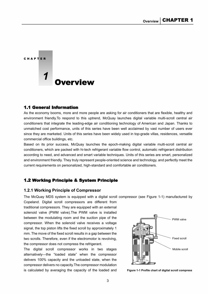
Figure 1-1 Profile chart of digital scroll compressor
PWM valve
Fixed scroll
Mobile scroll
1.1 General InformationAs the economy booms, more and more people are asking for air conditioners that are flexible, healthy and environment friendly.To respond to this uptrend, McQuay launches digital variable multi-scroll central airconditioners that integrate the leading-edgeairconditioning technologyofAmericanandJapan.Thanks tounmatchedcostperformance,unitsof thisserieshavebeenwellacclaimedbyvastnumberofuserseversincetheyaremarketed.Unitsofthisserieshavebeenwidelyusedintop-gradevillas,residences,versatilecommercial office buildings, etc.Based on its prior success, McQuay launches the epoch-making digital variable multi-scroll central airconditioners, which are packed with hi-tech refrigerant variable flow control, automatic refrigerant distribution accordingtoneed,andadvancedandsmartvariabletechniques.Unitsofthisseriesaresmart,personalizedandenvironmentfriendly.Theytrulyrepresentpeople-orientedscienceandtechnology,andperfectlymeetthecurrentrequirementsonpersonalized,high-standardandcomfortableairconditioners.
1.2 Working Principle & System Principle
1.2.1 Working Principle of CompressorThe McQuay MDS system is equipped with a digital scroll compressor (see Figure 1-1) manufactured byCopeland. Digital scroll compressors are different fromtraditionalcompressors.Theyareequippedwithanexternalsolenoid valve (PWM valve).The PWM valve is installedbetween the modulating room and the suction pipe of thecompressor. When the solenoid valve receives a voltagesignal, the top piston lifts the fixed scroll by approximately 1 mm. The move of the fixed scroll results in a gap between the twoscrolls.Therefore,eveniftheelectromotorisrevolving,thecompressordoesnotcompresstherefrigerant.The digital scroll compressor works in two stagesalternatively—the “loaded state” when the compressordelivers 100% capacity and the unloaded state, when thecompressordeliversnocapacity.Thecompressormodulationis calculated by averaging the capacity of the loaded and
C H A P T E R
1 Overview
4
McQuay Air Conditioning MDS Multi System
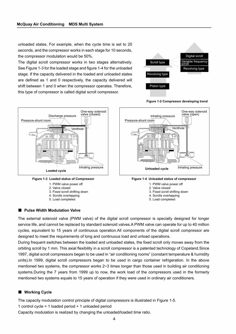
Scroll type
Revolving type
Piston type
Digital scroll
Variable frequency scroll
Revolving type
Figure 1-2 Compressor developing trend
1. PWM valve power off2. Valve closed3. Fixed scroll shifting down4. Scrolls overlapping5. Load completed
1. PWM valve power off2. Valve closed3. Fixed scroll shifting down4. Scrolls overlapping5. Load completed
Pressure-shunt roomDischarge pressure
One-way solenoid valve (closed)
Pressure-shunt roomInhaling pressure
Venthole
Inhaling pressureUnloaded cycle
One-way solenoid valve (open)
Venthole
Inhaling pressureLoaded cycle
Figure 1-3 Loaded status of Compressor Figure 1-4 Unloaded status of compressor
unloadedstates.Forexample,when thecycle time isset to20seconds,andthecompressorworksineachstagefor10seconds,thecompressormodulationwouldbe50%.The digital scroll compressor works in two stages alternatively.See Figure 1-3 for the loaded stage and figure 1-4 for the unloaded stage.Ifthecapacitydeliveredintheloadedandunloadedstatesare defined as 1 and 0 respectively, the capacity delivered will shiftbetween1and0whenthecompressoroperates.Therefore,thistypeofcompressoriscalleddigitalscrollcompressor.
Pulse Width Modulation Valve
The external solenoid valve (PWM valve) of the digital scroll compressor is specially designed for longerservicelife,andcannotbereplacedbystandardsolenoidvalves.APWMvalvecanoperateforupto40millioncycles,equivalent to15yearsof continuousoperation.All componentsof thedigital scroll compressoraredesignedtomeettherequirementsoflongandcontinuousloadandunloadoperations.During frequent switches between the loaded and unloaded states, the fixed scroll only moves away from the orbiting scroll by 1 mm. This axial flexibility in a scroll compressor is a patented technology of Copeland.Since 1997,digitalscrollcompressorsbegantobeusedin“airconditioningrooms”(constanttemperature&humidityunits).In 1999, digital scroll compressors began to be used in cargo container refrigeration. In the abovementionedtwosystems,thecompressorworks2~3timeslongerthanthoseusedinbuildingairconditioningsystems.During the7 years from1999up tonow, thework loadof the compressorsused in the formerlymentionedtwosystemsequalsto15yearsofoperationiftheywereusedinordinaryairconditioners.
Working Cycle
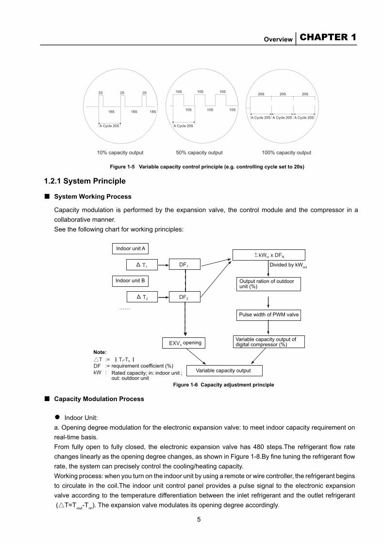
ThecapacitymodulationcontrolprincipleofdigitalcompressorsisillustratedinFigure1-5.1controlcycle=1loadedperiod+1unloadedperiodCapacitymodulationisrealizedbychangingtheunloaded/loadedtimeratio.
■
■
5
CHAPTER 1Overview
2S
18S 18S 18S
A Cycle 20S A Cycle 20S
A Cycle 20S A Cycle 20S A Cycle 20S
10% capacity output 50% capacity output 100% capacity output
2S 2S 10S 10S 10S
10S 10S 10S
20S 20S 20S
Figure 1-5 Variable capacity control principle (e.g. controlling cycle set to 20s)
Indoor unit A
Indoor unit B
opening
Variable capacity outputrequirement coefficient (%)Rated capacity; in: indoor unit ; out: outdoor unit
Note:
Variable capacity output of digital compressor (%)
Output ration of outdoor unit (%)
Divided by kWout
Pulse width of PWM valve
Figure 1-6 Capacity adjustment principle
1.2.1 System Principle
System Working Process
Capacitymodulation isperformedby theexpansionvalve, thecontrolmoduleand thecompressor inacollaborativemanner.Seethefollowingchartforworkingprinciples:
■
Capacity Modulation Process
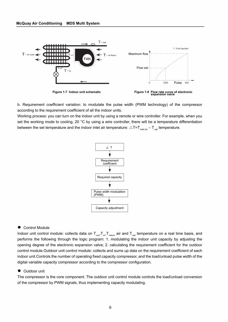
IndoorUnit:a.Openingdegreemodulationfortheelectronicexpansionvalve:tomeetindoorcapacityrequirementonreal-timebasis.From fully open to fully closed, the electronic expansion valve has 480 steps.The refrigerant flow rate changes linearly as the opening degree changes, as shown in Figure 1-8.By fine tuning the refrigerant flow rate,thesystemcanpreciselycontrolthecooling/heatingcapacity.Workingprocess:whenyouturnontheindoorunitbyusingaremoteorwirecontroller,therefrigerantbeginstocirculate in thecoil.The indoorunitcontrolpanelprovidesapulsesignal to theelectronicexpansionvalveaccordingtothetemperaturedifferentiationbetweentheinletrefrigerantandtheoutletrefrigerant(△T=T-out-T-in).Theexpansionvalvemodulatesitsopeningdegreeaccordingly.
■
●
6
McQuay Air Conditioning MDS Multi System
T-midAir Uutlet Air Return
T - To Be Specified
Maximum flow
Flow set
Pulse
Figure 1-7 Indoor unit schematic Figure 1-8 Flow rate curve of electronic expansion valve
Requirement coefficient
Required capacity
Pulse width modulation (PWM)
Capacity adjustment
T
b. Requirement coefficient variation: to modulate the pulse width (PWM technology) of the compressor according to the requirement coefficient of all the indoor units.Workingprocess:youcanturnontheindoorunitbyusingaremoteorwirecontroller.Forexample,whenyousettheworkingmodetocooling,20°Cbyusingawirecontroller,therewillbeatemperaturedifferentiationbetweenthesettemperatureandtheindoorinletairtemperature:△T=T-inletair–T-settemperature.
ControlModuleIndoorunitcontrolmodule:collectsdataonT-out,T-in,T-returnairandT-settemperatureonarealtimebasis,andperforms the following through the logic program: 1. modulating the indoor unit capacity by adjusting theopening degree of the electronic expansion valve; 2. calculating the requirement coefficient for the outdoor control module.Outdoor unit control module: collects and sums up data on the requirement coefficient of each indoor unit.Controls the number of operating fixed capacity compressor, and the load/unload pulse width of the digital variable capacity compressor according to the compressor configuration.
OutdoorunitThecompressoristhecorecomponent.Theoutdoorunitcontrolmodulecontrolstheload/unloadconversionofthecompressorbyPWMsignals,thusimplementingcapacitymodulating.
●
●
7
CHAPTER 1Overview
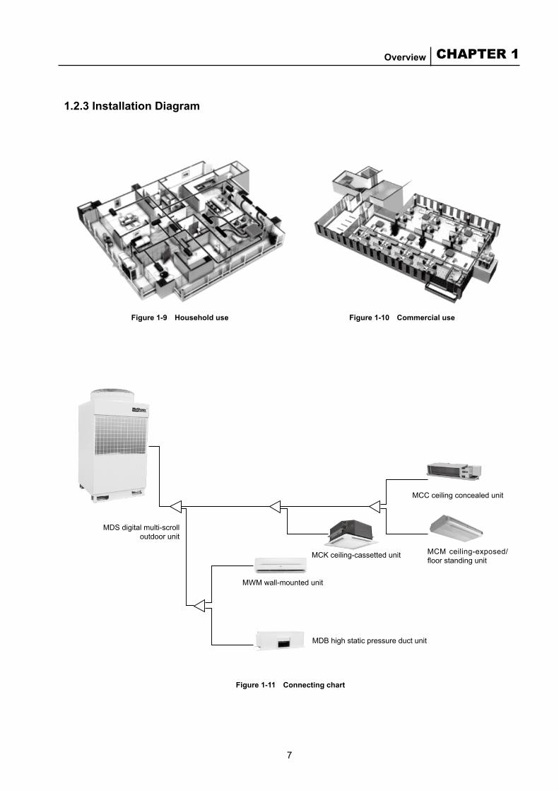
Figure 1-11 Connecting chart
1.2.3 Installation Diagram
MDSdigitalmulti-scrolloutdoorunit
MWMwall-mountedunit
MDBhighstaticpressureductunit
MCKceiling-cassettedunit
MCCceilingconcealedunit
MCMceiling-exposed/floor standing unit
Figure 1-9 Household use Figure 1-10 Commercial use
8
McQuay Air Conditioning MDS Multi System
100
90
80
70
60
50
40
30
20
10
0 10 20 30 40 50 60 70 80 90 100
100%
10%
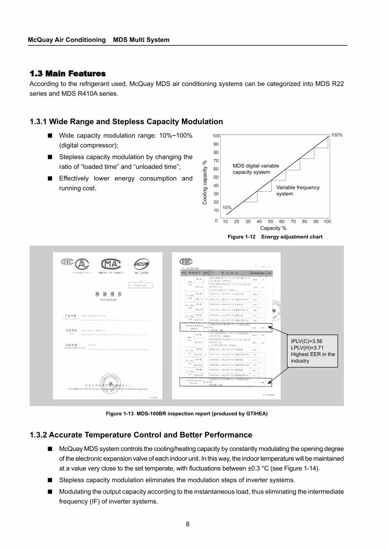
Figure 1-12 Energy adjustment chart
Coo
ling
capa
city
% MDS digital variable capacity system
Variable frequency system
Capacity %
1.3 Main FeaturesAccordingtotherefrigerantused,McQuayMDSairconditioningsystemscanbecategorizedintoMDSR22seriesandMDSR410Aseries.
1.3.1 Wide Range and Stepless Capacity ModulationWidecapacitymodulation range:10%~100%(digitalcompressor);
Steplesscapacitymodulationbychangingtheratioof“loadedtime”and“unloadedtime”;
Effectively lower energy consumption andrunningcost.
■
■
■
Figure 1-13 MDS-100BR inspection report (produced by GTIHEA)
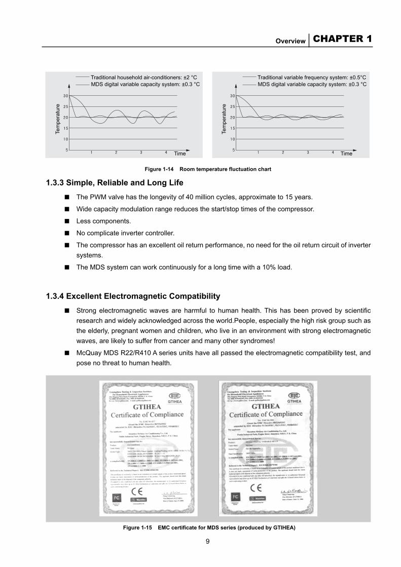
1.3.2 Accurate Temperature Control and Better PerformanceMcQuayMDSsystemcontrolsthecooling/heatingcapacitybyconstantlymodulatingtheopeningdegreeoftheelectronicexpansionvalveofeachindoorunit.Inthisway,theindoortemperaturewillbemaintainedat a value very close to the set temperate, with fluctuations between ±0.3 °C (see Figure 1-14).
Steplesscapacitymodulationeliminatesthemodulationstepsofinvertersystems.
Modulatingtheoutputcapacityaccordingtotheinstantaneousload,thuseliminatingtheintermediatefrequency(IF)ofinvertersystems.
■
■■
IPLV(C)=3.56LPLV(H)=3.71HighestEERintheindustry
9
CHAPTER 1Overview
Figure 1-14 Room temperature fluctuation chart
Traditional household air-conditioners: ±2 °C MDS digital variable capacity system: ±0.3 °C
Time Time
Traditional variable frequency system: ±0.5°CMDS digital variable capacity system: ±0.3 °C
Tem
pera
ture
Tem
pera
ture
Figure 1-15 EMC certificate for MDS series (produced by GTIHEA)
1.3.3 Simple, Reliable and Long LifeThePWMvalvehasthelongevityof40millioncycles,approximateto15years.
Widecapacitymodulationrangereducesthestart/stoptimesofthecompressor.
Lesscomponents.
Nocomplicateinvertercontroller.
Thecompressorhasanexcellentoilreturnperformance,noneedfortheoilreturncircuitofinvertersystems.
TheMDSsystemcanworkcontinuouslyforalongtimewitha10%load.
1.3.4 Excellent Electromagnetic CompatibilityStrong electromagnetic waves are harmful to human health. This has been proved by scientific researchandwidelyacknowledgedacrosstheworld.People,especiallythehighriskgroupsuchastheelderly,pregnantwomenandchildren,wholiveinanenvironmentwithstrongelectromagneticwaves,arelikelytosufferfromcancerandmanyothersyndromes!
McQuayMDSR22/R410Aseriesunitshaveallpassedtheelectromagneticcompatibilitytest,andposenothreattohumanhealth.
■■■■■
■
■
■
10
McQuay Air Conditioning MDS Multi System
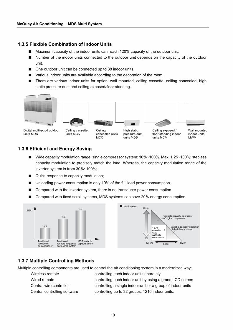
Digital multi-scroll outdoor units MDS
Ceiling cassette units MCK
Ceiling concealed units MCC
High static pressure duct units MDB
Ceiling exposed / floor standing indoor units MCM
Wall mounted indoor units MWM
Traditional household air-conditioner
EER
2.5
2.8
3.3
Traditional variable frequency multi-scroll system
MDS variable capacity sytem
10HP system
Variable capacity operation of digital compressor
100% operation of fixed capacity compressor
Loadhigher lower
Variable capacity operation of digital compressor
1.3.5 Flexible Combination of Indoor UnitsMaximumcapacityoftheindoorunitscanreach120%capacityoftheoutdoorunit.Numberoftheindoorunitsconnectedtotheoutdoorunitdependsonthecapacityoftheoutdoorunit.Oneoutdoorunitcanbeconnectedupto38indoorunits.Variousindoorunitsareavailableaccordingtothedecorationoftheroom.Therearevarious indoorunits foroption:wallmounted,ceilingcassette,ceilingconcealed,highstatic pressure duct and ceiling exposed/floor standing.
■■
■■■
1.3.7 Multiple Controlling MethodsMultiplecontrollingcomponentsareusedtocontroltheairconditioningsysteminamodernizedway:
Wirelessremote controllingeachindoorunitseparatelyWiredremote controllingeachindoorunitbyusingagrandLCDscreenCentralwirecontroller controllingasingleindoorunitoragroupofindoorunitsCentralcontrollingsoftware controllingupto32groups,1216indoorunits.
1.3.6 Efficient and Energy SavingWidecapacitymodulationrange:singlecompressorsystem:10%~100%,Max.1.25~100%;steplesscapacitymodulation topreciselymatch the load.Whereas, thecapacitymodulation rangeof theinvertersystemisfrom30%~100%;
Quickresponsetocapacitymodulation;
Unloadingpowerconsumptionisonly10%ofthefullloadpowerconsumption.
Comparedwiththeinvertersystem,thereisnotransducerpowerconsumption.
Compared with fixed scroll systems, MDS systems can save 20% energy consumption.
■
■■■■

11
CHAPTER 1Overview
Model Wired controller Card remote controller Wireless remote controller Central Wired controller
MCCceilingconcealedunit Standard Optional N/A Optional
MDBhighstaticpressureductunit Standard Optional N/A Optional
MCKceiling-cassettedunit Optional N/A Standard Optional
MCM ceiling-exposed/floor standing unit Optional N/A Standard Optional
MWMwall-mountedunit N/A N/A Standard Optional
1.3.8 Reliable Long Stud Piping
R22 Series
Thesystemsupportsamaximumpipinglengthof150m(12HP-32HP)andamaximumfallof50m(3HP-32HP).
■
Unit capacity Max. total pipe length (m) Max. pipe length (m)Fall (m)
Positive (m) Negative (m)
8~32HP 500 150 50 40
6~7HP 150 70 30 30
3~5HP 100 50 20 20
Note: Positivefallmeanstheoutdoorunitisabovetheindoorunit.Negativefallmeanstheoutdoorunitisbelowtheindoorunit.
R410A Series
Thesystemsupportsamaximumpipinglengthof175m(12HP-50HP)andamaximumfallof50m(8HP-50HP).
■
Unit capacity Max. total pipe length (m) Max. pipe length (m)Fall (m)
Positive (m) Negative (m)
8~50HP 500 150 50 40
6~7HP 150 70 30 30
5HP 100 50 20 20
Note:Positivefallmeanstheoutdoorunitisabovetheindoorunit.Negativefallmeanstheoutdoorunitisbelowtheindoorunit.
Wiredcontroller+cardstyleremote(optional) Wirelessremote
12
McQuay Air Conditioning MDS Multi System
1.3.10 Easy to Install and Simple to Maintain
Easy installation
MDSsystemissimplewithclearpipelayout.Fieldinstallationonlyinvolvesinstallingandconnectingtheindoorandoutdoorunits.Therefrigerantpipesareeasytoinstallandsimpletomaintain.
Independent system, installed by stages
EasyinstallationallowstheownertochooseasuitabletimefortheMDSsysteminstallationinalongerperiod,greatly reducing the time limitationon theairconditioner installationduring theconstructionstage.Fornewprojects,installingbystagescanreducelump-suminvestment.Foralterationprojects,itiseasyfortheownertoinstall.
No need for special maintenance
Itonlyinvolvessimplerefrigerantpipingsystem,withoutcomplexmaintenance;Comparedwithwater-cooledsystem,ithasnowatersystem.Therefore,nowaterpipecleaningandwater system maintaining work is involved.The system is easy to use, and requires no dedicatedmanagementandmaintenancepersonnel.
1.3.11 Wide Application RangeMDSsystemsarehigh-techcooling/heatingairconditioningsystemsequippedwithdigitallycontrolledvariablecapacitycompressor.Multipleindoorunitscanconnecttooneoutdoorunit.Theyareanewgeneration of modular multi-scroll systems after the efficiency of air conditioners became a major concern.Theymeettheairconditioningrequirementsoftallbuildingsperfectly.
MDS systems are applicable to various buildings such as offices, apartments, shopping malls, hotels, hospitalsandschools.Inaddition,theyareeasytoinstallandmaintain.Inthissense,theymeetthevariousrequirementsofairconditionermarkets.
■●
■●
●●
■●●
■
■
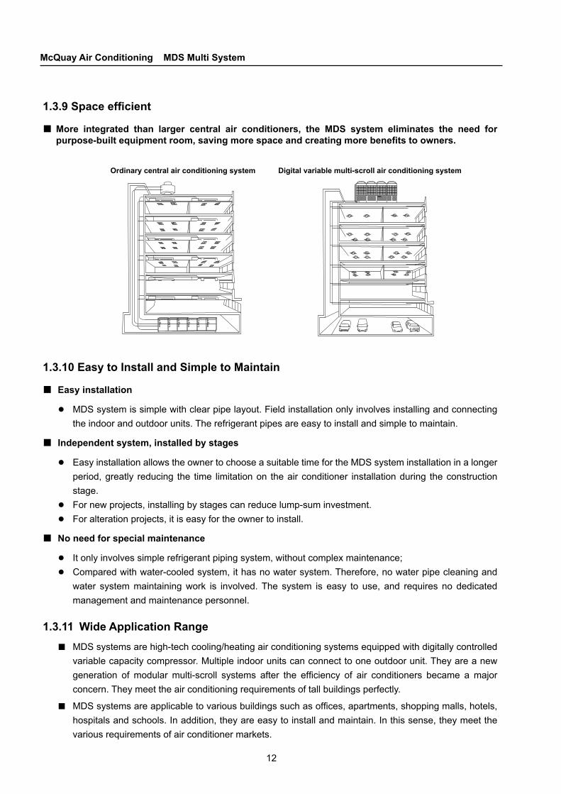
1.3.9 Space efficient
More integrated than larger central air conditioners, the MDS system eliminates the need for purpose-built equipment room, saving more space and creating more benefits to owners.
■
Digital variable multi-scroll air conditioning systemOrdinary central air conditioning system
13
CHAPTER 1Overview
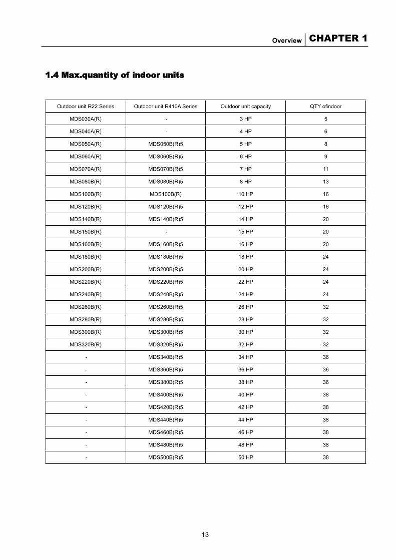
OutdoorunitR22Series OutdoorunitR410ASeries Outdoorunitcapacity QTY ofindoor
MDS030A(R) - 3HP 5
MDS040A(R) - 4HP 6
MDS050A(R) MDS050B(R)5 5HP 8
MDS060A(R) MDS060B(R)5 6HP 9
MDS070A(R) MDS070B(R)5 7HP 11
MDS080B(R) MDS080B(R)5 8HP 13
MDS100B(R) MDS100B(R) 10HP 16
MDS120B(R) MDS120B(R)5 12HP 16
MDS140B(R) MDS140B(R)5 14HP 20
MDS150B(R) - 15HP 20
MDS160B(R) MDS160B(R)5 16HP 20
MDS180B(R) MDS180B(R)5 18HP 24
MDS200B(R) MDS200B(R)5 20HP 24
MDS220B(R) MDS220B(R)5 22HP 24
MDS240B(R) MDS240B(R)5 24HP 24
MDS260B(R) MDS260B(R)5 26HP 32
MDS280B(R) MDS280B(R)5 28HP 32
MDS300B(R) MDS300B(R)5 30HP 32
MDS320B(R) MDS320B(R)5 32HP 32
- MDS340B(R)5 34HP 36
- MDS360B(R)5 36HP 36
- MDS380B(R)5 38HP 36
- MDS400B(R)5 40HP 38
- MDS420B(R)5 42HP 38
- MDS440B(R)5 44HP 38
- MDS460B(R)5 46HP 38
- MDS480B(R)5 48HP 38
- MDS500B(R)5 50HP 38
1.4 Max.quantity of indoor units

14
McQuay Air Conditioning MDS Multi System
C H A P T E R
2.1 Introduction to the ControllerMDS system is controlled by micro-computers. Several types of controller are available, including wireless controller, wired controller, wired controller + remote controller and central controller.One wireless controller can control one indoor unit. One wired controller can control one indoor unit . The central controller can control up to 32 units.
2.2 Main Functions
Cooling/heating/air supply/dehumidification modes are available LCD wired controller and remote control are available, or remote control onlyDigital scroll compressor is used for load balancing to reduce the start/stop times of the constant-capacity compressorElectronic expansion valve is used to control the refrigerant flowOne outdoor unit can connect up to 38 indoor units(R410A) or 32 indoor units(R22).Networking control is available2/3-speed outdoor unit fan speed and 3-speed indoor unit fan speed controlTimer for ON/OFF with precision up to minuteEnergy-saving mode is available for both cooling and heating modesHigh/low pressure protection/overload protection for the compressorOverload protection for fans of indoor and outdoor units Anti-icing function for the indoor unit coilAuto restart when powered onAuto/manual defrost mode is availableAuto error checking for the temperature sensorOverheat protection for the indoor unit coil during heating operationError displayTemperature unit can be ℃ or ℉
■■■
■■■■■■■■■■■■■■■
2 Unit Control

15
CHAPTER 2Unit Control
Reset key Reset key
CLK key CLK key
Timer Timer
Fresh air
Fan FanMode Mode
Sleep
Match with MDS units Match with fresh air fans
LCD LCD screen
Temp. Temp.
SleepHeat/Swing
2.3 Operation of the Controller
2.3.1 Main FeaturesBoth the keyboard and the remote (equipped with infrared receiver to receive orders) can be used for controlling the unit, such as setting parameters, working mode, display status and error indication.Features:
Working modeCooling only unit: cooling/air supply/dehumidification; Heat pump unit: cooling/heating/air supply/dehumidification.
Indoor unit fan have several speed: Auto/Low/Medium/High. 1-speed fan does not have this feature.Temperature range: 16 ℃ (61 ℉) ~ 30 ℃ (86 ℉)Timer for ON/OFF. Max. time is 24 hours.Sleep mode which makes sleeping more comfortableAuxiliary electric heater & hot water heater control and wind wing function (optional). LCD is used to display the temperature setting, working mode, real time timer, week day, and ON/OFF status of the unit.
2.3.2 Operation of the Wire Controller
Keys on the wired controller panel
■
■■■■■■
■
Operation guide
Default parameterIf auto restart after power is not active: OFF, 24 ℃/75 ℉, cooling, high speed, no sleep, no manual defrost, no wind wing, no electric heater. If auto restart after power is active: the unit is restored to its status before the power failure.
■●
16
McQuay Air Conditioning MDS Multi System
Temperature settingNormally, pressing △ or ▽ key can immediately increase or decrease the set temperature by 1 ℃ or 1 ℉. Meanwhile, the backlight will light up. The temperature setting range is 16 ~ 30 ℃ (61 ~ 86 ℉). When the set temperature reaches the highest or lowest limit, the △ or ▽ becomes invalid.
Temperature unit settingThere is a dial switch on the PCB board. You can select the temperature unit according to your own habit by turning the OP1 switch to ON or OFF. When the switch OP1 is ON, the unit is ℃; when it is OFF, the unit is ℉. To switch between the two units, you can press and hold the Fan key for 5 seconds in normal condition. The buzzer buzzes if the switch is successful.
Real time settingIn normal condition, you can press CLK once to set the week day. When the week icon appears, you can press the △ or ▽ key to set the week day, ranging from Sunday to Saturday. Meanwhile, the timer does not change. Do not press any key in five seconds and wait until the controller is restored to normal condition. Then pressing CLK again will complete the week day setting. Meanwhile, the timer icon appears, and the time displayed start twinkling. At this time, you can press △ once to increase Hour by 1, or press ▽ once to increase Minute by 1. When you press and hold △ or ▽, Hour or Minute increases faster. Do not press any key in five seconds. Wait until the time displayed stops twinkling. The set time has not been saved yet. You need to Press CLK again to confirm the time setting. Otherwise, the time setting will not take effect. If you press any other irrelevant key, the time setting mode is terminated, and the setting will not be saved.
Mode settingWhen the unit is OFF, you can press the Mode Key to set the mode. When you press the Mode key, the current mode starts twinkling. Every time you press the Mode key, the mode changes once in the following order:When the outdoor unit is OFF:Heat pump: Cooling → Heating → Air supply → Dehumidification → CoolingCooling only: Cooling → Air supply → Dehumidification → CoolingWhen the outdoor unit is in cooling mode: Cooling → Air supply → Dehumidification → CoolingWhen the outdoor unit is in heating mode: Heating → Air supply → HeatingNote: indoor units within the same system cannot be some units cooling, while others heating at the same time.
Air flow settingIn normal condition, when you press the Fan key, the air flow changes in the following order:High → Auto → Low → Medium → High. The Auto feature is not available for the air supply mode.
SleepWhen you press the Sleep key, the Sleep icon will light up or turn off, indicating this feature is ON or OFF.
Auto restart after powered onWhen you turn the OP2 dial switch (on the PCB board) to OK, the feature of auto restart after powered on will be activated, and there will be an icon indicating so at the lower left corner of the LCD.
●
●
●
●
●
●
●
17
CHAPTER 2Unit Control
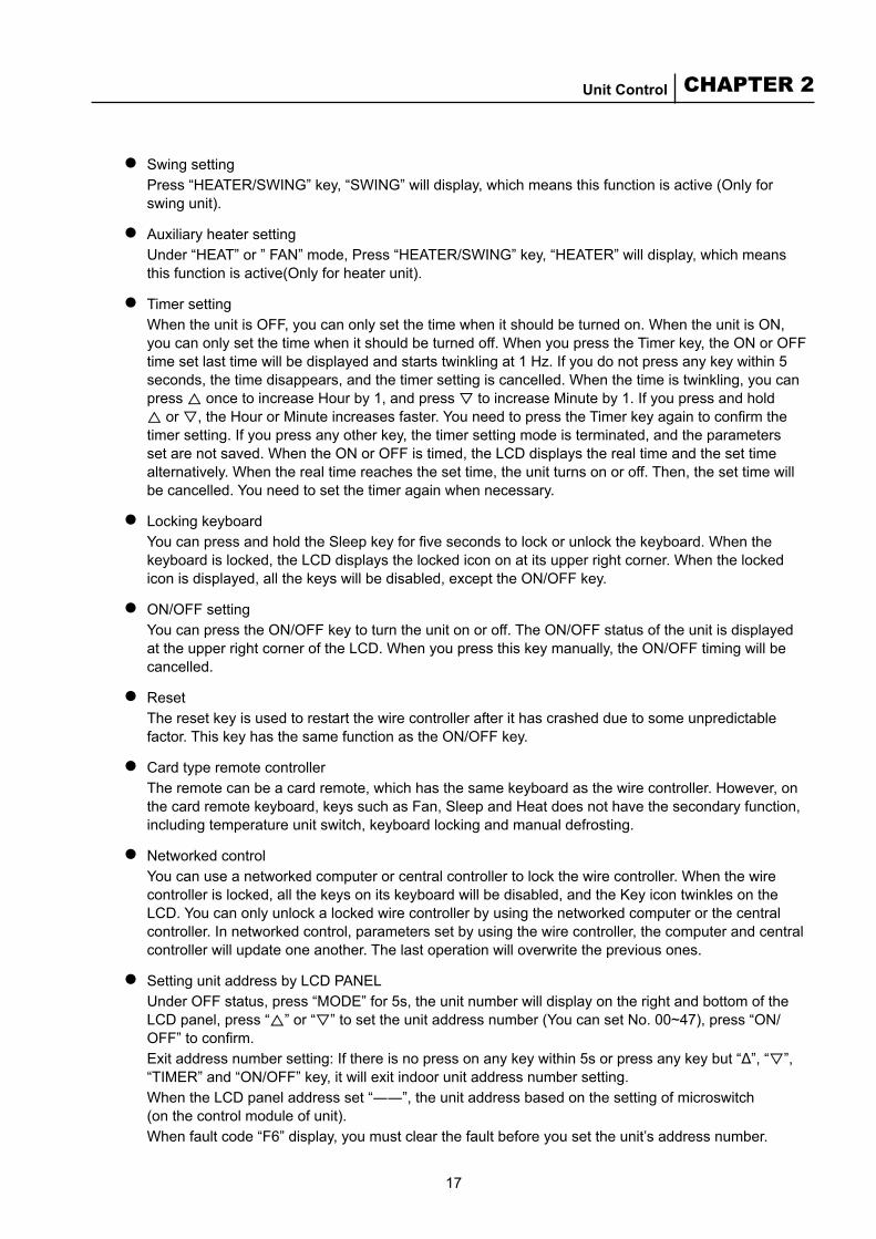
Swing settingPress “HEATER/SWING” key, “SWING” will display, which means this function is active (Only for swing unit).
Auxiliary heater setting Under “HEAT” or ” FAN” mode, Press “HEATER/SWING” key, “HEATER” will display, which means this function is active(Only for heater unit).
Timer settingWhen the unit is OFF, you can only set the time when it should be turned on. When the unit is ON, you can only set the time when it should be turned off. When you press the Timer key, the ON or OFF time set last time will be displayed and starts twinkling at 1 Hz. If you do not press any key within 5 seconds, the time disappears, and the timer setting is cancelled. When the time is twinkling, you can press △ once to increase Hour by 1, and press ▽ to increase Minute by 1. If you press and hold △ or ▽, the Hour or Minute increases faster. You need to press the Timer key again to confirm the timer setting. If you press any other key, the timer setting mode is terminated, and the parameters set are not saved. When the ON or OFF is timed, the LCD displays the real time and the set time alternatively. When the real time reaches the set time, the unit turns on or off. Then, the set time will be cancelled. You need to set the timer again when necessary.
Locking keyboardYou can press and hold the Sleep key for five seconds to lock or unlock the keyboard. When the keyboard is locked, the LCD displays the locked icon on at its upper right corner. When the locked icon is displayed, all the keys will be disabled, except the ON/OFF key.
ON/OFF settingYou can press the ON/OFF key to turn the unit on or off. The ON/OFF status of the unit is displayed at the upper right corner of the LCD. When you press this key manually, the ON/OFF timing will be cancelled.
ResetThe reset key is used to restart the wire controller after it has crashed due to some unpredictable factor. This key has the same function as the ON/OFF key.
Card type remote controllerThe remote can be a card remote, which has the same keyboard as the wire controller. However, on the card remote keyboard, keys such as Fan, Sleep and Heat does not have the secondary function, including temperature unit switch, keyboard locking and manual defrosting.
Networked controlYou can use a networked computer or central controller to lock the wire controller. When the wire controller is locked, all the keys on its keyboard will be disabled, and the Key icon twinkles on the LCD. You can only unlock a locked wire controller by using the networked computer or the central controller. In networked control, parameters set by using the wire controller, the computer and central controller will update one another. The last operation will overwrite the previous ones.
Setting unit address by LCD PANEL Under OFF status, press “MODE” for 5s, the unit number will display on the right and bottom of the LCD panel, press “△” or “▽” to set the unit address number (You can set No. 00~47), press “ON/OFF” to confirm.Exit address number setting: If there is no press on any key within 5s or press any key but “Δ”, “▽”, “TIMER” and “ON/OFF” key, it will exit indoor unit address number setting. When the LCD panel address set “――”, the unit address based on the setting of microswitch (on the control module of unit).When fault code “F6” display, you must clear the fault before you set the unit’s address number.
●
●
●
●
●
●
●
●
●
18
McQuay Air Conditioning MDS Multi System
Fan ON/OFF
Temp.
ON/OFF
Temp.
ON/OFF
Temp.
ON/OFF ON/OFF
Temp. Temp.
Fan speed Sleep
Timer TimerMode
Fan
Sleep
Timer Timer
Sleep Sleep
Mode
Fan
Mode
Fan
Heat
Timer
SleepHeat
Mode
Fan
Mode
For three-speed unit with swing
For the cooling andheat pump unit withthree-speed
For the cooling andheat pump unit withsingle-speed
For three speedunit with auxiliaryheater
For single speedunit with auxiliaryheater
Heat
Fan
Fan
ON/OFF
Sleep
Timer ModeModeTemp. Temp.
Temp.
Timer TimerHeat/Swing Sleep SleepFresh air
Fan Mode
LCD screen LCD screen
Unit: mm
CAUTION:The Connector(A) must be protected by insulating pipe A
To control Module
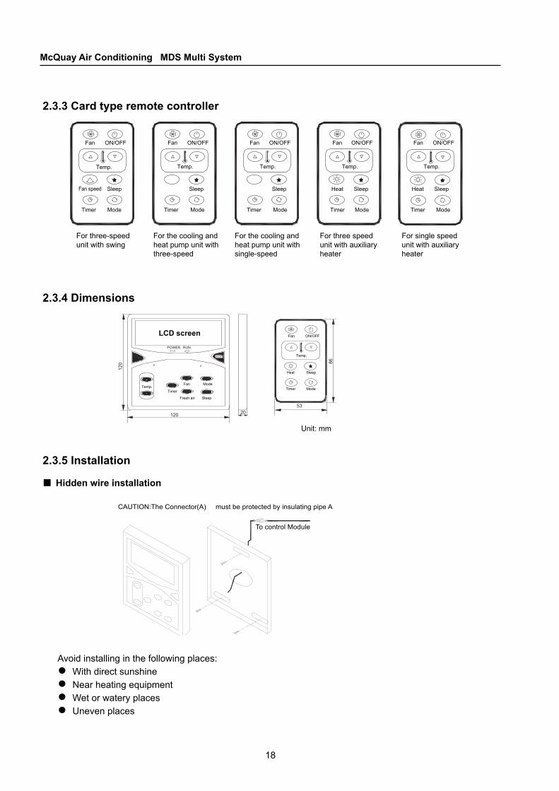
2.3.3 Card type remote controller
2.3.4 Dimensions
2.3.5 Installation
Hidden wire installation■
Avoid installing in the following places:With direct sunshineNear heating equipmentWet or watery placesUneven places
●●●●
19
CHAPTER 2Unit Control
RESET KEY CLOCK KEY
LCD
TEMP
ENTER FAN MODE
TIMER SWING UNIT No.
SETUP HEATER SLEEP
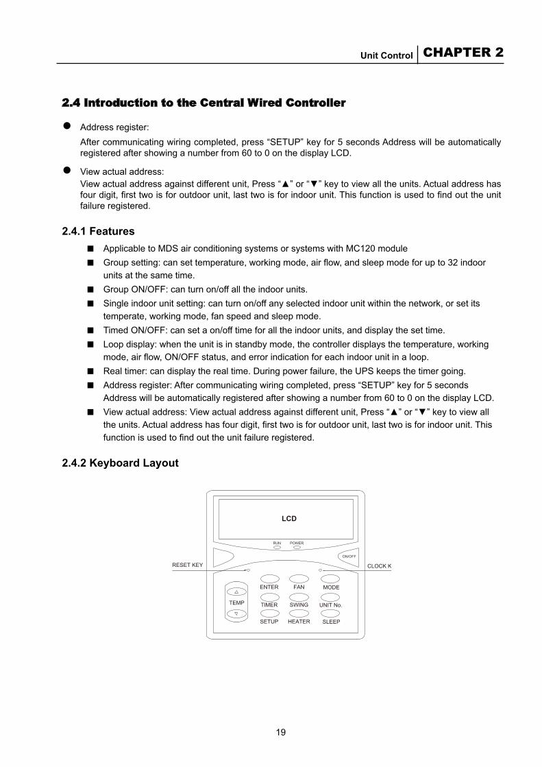
2.4 Introduction to the Central Wired Controller
Address register: After communicating wiring completed, press “SETUP” key for 5 seconds Address will be automatically
registered after showing a number from 60 to 0 on the display LCD.
View actual address: View actual address against different unit, Press “▲” or “▼” key to view all the units. Actual address has
four digit, first two is for outdoor unit, last two is for indoor unit. This function is used to find out the unit failure registered.
2.4.1 FeaturesApplicable to MDS air conditioning systems or systems with MC120 moduleGroup setting: can set temperature, working mode, air flow, and sleep mode for up to 32 indoor units at the same time.Group ON/OFF: can turn on/off all the indoor units.Single indoor unit setting: can turn on/off any selected indoor unit within the network, or set its temperate, working mode, fan speed and sleep mode.Timed ON/OFF: can set a on/off time for all the indoor units, and display the set time.Loop display: when the unit is in standby mode, the controller displays the temperature, working mode, air flow, ON/OFF status, and error indication for each indoor unit in a loop.Real timer: can display the real time. During power failure, the UPS keeps the timer going.Address register: After communicating wiring completed, press “SETUP” key for 5 seconds Address will be automatically registered after showing a number from 60 to 0 on the display LCD.View actual address: View actual address against different unit, Press “▲” or “▼” key to view all the units. Actual address has four digit, first two is for outdoor unit, last two is for indoor unit. This function is used to find out the unit failure registered.
2.4.2 Keyboard Layout
●
●
■■
■■
■■
■■
■

20
McQuay Air Conditioning MDS Multi System
Earthed screen layer Connected screen layers Connected screen layers
Indoor unit Indoor unit Indoor unit
Disconnected screen layer
Power adapter
2.4.3 Installation Wiring Diagram
Address setting for units with MC201 module■Address number SW2.1 SW2.2 SW2.3 SW2.4 SW2.5 SW2.6
0 0 0 0 0 0 0
1 0 0 0 0 0 1
2 0 0 0 0 1 0
3 0 0 0 0 1 1
4 0 0 0 1 0 0
5 0 0 0 1 0 1
6 0 0 0 1 1 0
7 0 0 0 1 1 1
8 0 0 1 0 0 0
9 0 0 1 0 0 1
10 0 0 1 0 1 0
11 0 0 1 0 1 1
12 0 0 1 1 0 0
13 0 0 1 1 0 1
14 0 0 1 1 1 0
15 0 0 1 1 1 1
16 0 1 0 0 0 0
17 0 1 0 0 0 1
18 0 1 0 0 1 0
Address number SW2.1 SW2.2 SW2.3 SW2.4 SW2.5 SW2.6
19 0 1 0 0 1 1
20 0 1 0 1 0 0
21 0 1 0 1 0 1
22 0 1 0 1 1 0
23 0 1 0 1 1 1
24 0 1 1 0 0 0
25 0 1 1 0 0 1
26 0 1 1 0 1 0
27 0 1 1 0 1 1
28 0 1 1 1 0 0
29 0 1 1 1 0 1
30 0 1 1 1 1 0
31 0 1 1 1 1 1
32 1 0 0 0 0 0
33 1 0 0 0 0 1
34 1 0 0 0 1 0
35 1 0 0 0 1 1
36 1 0 0 1 0 0
37 1 0 0 1 0 1
Wiring diagram for units equipped with MC201 module■
The jumper of the last indoor unit of the system must be set "close".Normal control MC301:JP1; Central controller MC303:JP2
21
CHAPTER 2Unit Control
2.4.4 Parameter Setting
Parameter setting for a single unitIn the loop display mode, you just need to press the Unit No. key to view and set the status for several indoor units. When the Unit No. is not displayed on the LCD, you can select the target indoor unit by pressing the ▲/▼ and OK key. Then the Unit No. starts twinkling on the LCD. The status of the related indoor unit is also displayed. You can now set parameters for the selected indoor unit.
Default ParameterWhen powered on, the LCD displays the parameters of each indoor unit in a loop: OFF, 24 ℃ /75 ℉, Cooling (MDS indoor unit)/Auto (other models), High air flow, No sleep, No wind wing, No heating.
ON/OFF operationYou can press the “ON/OFF” key to turn on/off the unit. The status of the unit is displayed at the upper right corner of the LCD. Do not press this key too frequently.
Mode settingWhen the unit is OFF, you can press the “Mode” Key to set the mode. When you press the Mode key, the current mode starts is displayed on the LCD. Every time you press the Mode key, the mode changes once in the following order:
◆ MDS model:When the outdoor unit is OFF:Heat pump: Cooling → Heating → Air supply → Dehumidification → CoolingCooling only: Cooling → Air supply → Dehumidification → CoolingWhen the outdoor unit is heating:Heating → Air supply → HeatingWhen the outdoor unit is cooling:Cooling → Air supply → Dehumidification → Cooling
◆ Non-MDS model:Cooling only: Cooling → Air supply → Dehumidification → CoolingHeat pump: Cooling → Heating → Auto → Air supply → Dehumidification → Cooling
Temperature settingNormally, pressing the ▲/▼ key once can immediately increase or decrease the set temperature by 1 ℃ or 1 ℉. Meanwhile, the backlight will light up. The temperature setting range is 16 ~ 30 ℃ (61 ~ 86 ℉). When the set temperature reaches the upper or lower limit, the ▲/▼ key becomes invalid.
Air flow settingIn normal condition, when you press the “Fan” key, the air flow changes in the following order:High → Auto → Low → Medium → High. The Auto feature is not available for the air supply mode.
Wind wing settingIn normal condition, when you press the “swing” key, the Wind wing icon on the upper right corner of the LCD lights up or turns off, indicating this feature is activated or inactivated. This feature is only available for units having the wind wing feature.
Sleep settingIn normal condition, when you press the “Sleep” key, the Sleep icon on the upper right corner of
■
●
●
●
●
●
●
●
22
McQuay Air Conditioning MDS Multi System
the LCD lights up or turns off, indicating this feature is activated or inactivated (this feature is only available when the unit is in Cooling, Heating or Auto mode).After completing all the settings, you can press the OK key to exit the single unit control mode and return to the loop display mode. If no key is pressed within 10 seconds, the single unit control mode automatically switches to the loop display mode.
Parameter setting for a group of unitsTo facilitate parameter setting, the controller also supports centralized group control over all the connected indoor units. In the loop display mode, you just need to press the “Unit No.” key. When the Unit No. is not displayed on the LCD, you can select the target indoor units by pressing the ▲/▼ and “Enter” key. Then the Unit No. starts twinkling on the LCD. You can now set parameters for the all the selected indoor units within the network, thus implementing group control.
Mode settingWhen the unit is OFF, you can press the “Mode” Key to set the mode. When you press the Mode key, the current mode starts is displayed on the LCD. Every time you press the Mode key, the mode changes once in the following order: Cooling → Heating → Air supply → Dehumidification → Cooling.
Temperature settingNormally, pressing the ▲/▼ button once can immediately increase or decrease the set temperature by 1 ℃ or 1 oF. Meanwhile, the backlight will light up. The temperature setting range is 16 ~ 30 ℃ (61 ~ 86 ℉). When the set temperature reaches the upper or lower limit, the ▲/▼ button becomes invalid.
Air flow settingIn normal condition, when you press the “Fan” key, the air flow changes in the following order: High → Auto → Low → Medium → High. The Auto feature is not available for the air supply mode.
Wind wing settingIn normal condition, when you press the “swing” key, the Wind wing icon on the upper right corner of the LCD lights up or turns off, indicating this feature is activated or inactivated. This feature is only available for units having the wind wing feature.
Sleep settingIn normal condition, when you press the “Sleep” key, the Sleep icon on the upper right corner of the LCD lights up or turns off, indicating this feature is activated or inactivated (this feature is only available when the unit is in Cooling, Heating or Auto mode).After completing all the settings, you can press the “Enter” key to exit the group control mode and return to the loop display mode. If no key is pressed within 10 seconds, the group control mode automatically switches to the loop display mode.
Group ON/OFF operationTo facilitate users, the controller also supports centralized group ON/OFF operation on all the connected indoor units.In the loop display mode, when you press and hold the “ON/OFF” key for 5 seconds, the Unit No. starts twinkling. The [ ] is displayed. You can then carry out ON/OFF operation on all the indoor units within the network. You can also carry out group ON/OFF operation in this way: Press the Unit No. key. When the Unit No. is not displayed on the LCD, you can select the target indoor units by pressing the ▲/▼ and “Enter” key. Then the Unit No. starts twinkling on the LCD. You can then carry out ON/OFF operation on all the indoor units within the network.
Note: After completing all the settings, you can press the “Enter” key to exit the group ON/OFF mode and return to the loop display mode. If no key is pressed within 10 seconds, the group ON/OFF mode automatically switches to the loop display mode.
■
●
●
●
●
●
●
23
CHAPTER 2Unit Control
Other settings
Temperature unit settingOn the PCB board, you can set the temperature unit by dialing the first bit of K1 to ON (℉) or OFF (℃).You can select a unit according to your own habit. To switch between ℉ and ℃, you just need to press “Fan” key for 5 seconds in normal condition.The buzzer buzzes when the switch is active.◆ Real time setting
In normal condition, when you press the “Clock” key on the upper right corner of the panel once, the Week icon is displayed at the lower left corner of the LCD. You can then press ▲/▼ to set the week, from Sunday to Saturday.Then you need to press the “Clock” key again to confirm the week setting. If no key is pressed within 5 seconds, the week setting mode will terminate and switch back to the normal condition. In this case, the setting made will be cancelled.
◆ After the week is set, the time setting icon appears. The time displayed starts twinkling. Then you can press ▲ once to increase Hour by 1, or press ▼ once to increase minute by 1. When you press and hold ▲ or ▼, Hour or Minute increases faster. If no key is pressed within 5 seconds, the time setting mode will terminate after the time displayed has twinkled for 5 times. In this case, the time setting will not be saved. To confirm the time setting, you need to press the “Clock” key again, otherwise the setting will be cancelled. If you press any other irrelevant key during time setting, the time setting mode will terminate and switch back to normal condition. In this case, the parameters set will not be saved.
Timer setting◆ To time ON operation, you can press the Timer key. When the Time ON is displayed on the LCD,
you can press ▲ once to increase Hour by 1, or press ▼ once to increase minute by 1. When you press and hold ▲ or ▼, Hour or Minute increases faster. To save the Time ON parameter, you need to press the OK key. You can also press another irrelevant key to exit without saving the parameter.
◆ To time OFF operation, you can press the Timer key. When the Time OFF is displayed on the LCD, you can press ▲ once to increase Hour by 1, or press ▼ once to increase minute by 1. When you press and hold ▲ or ▼, Hour or Minute increases faster. To save the Time OFF parameter, you need to press the OK key. You can also press another irrelevant key to exit without saving the parameter.
◆ To cancel timed ON/OFF, you can press and hold “Timer” for 5 seconds. The buzzer buzzes once. Then the timed ON/OFF parameters are cleared.
◆ Timed ON/OFF indication: if such a time is set, it is displayed every 5 seconds. If cleared or not set, no such time is displayed.
ResetThe reset key at the upper left corner of the panel is used to restart the unit. This key has the same function as the ON/OFF key.
2.4.5 Notice
TroubleshootingThe LCD displays the status of all the indoor units in a loop. If an error takes place in some indoor unit, the error code will be displayed on the LCD. The error code represents the address of the indoor unit. The code related to the specific error is displayed on the wire controller of the indoor unit on which the error has occurred.
■●
●
●
■
24
McQuay Air Conditioning MDS Multi System
TEMP
ENTER FAN MODE
TIMER SWING UNIT No.
SETUP HEATER SLEEP
LCD
The buzzerIf a key is pressed and the operation is successful, the buzzer buzzes, otherwise it does not buzz.
Back lightWhen the unit is powered on or a key is pressed, the back light lights up for 5 seconds and goes off.
LED indicatorMC303 central wire controller has two LED indicators, one is for “Power”, and the other for the operation status---“Run”. When MC303 is powered on, the Power indicator lights up. When some indoor unit is working, the Operation indicator lights up.
Communication troubleshootingIf the central controller cannot acquire the status of an indoor unit, it means they cannot communicate with each other. In this case, the central controller will skip the unit and move on to display the status of another indoor unit.
Special troubleshooting
Auto mode for interconnection:IfMDS indoor units and ordinary indoor units are interconnected, you cannot set the central wire controller to Auto mode. You can set an ordinary indoor unit to Auto mode, but cannot set aMDS indoor unit to Auto mode.
Mode clash for group ON/OFF operationThe outdoor unit works in the mode that is firstly set. The indoor unit will turn off in case of mode clash.
Group operation for interconnected cooling only and heat pump unitsIf you set the wire controller to the heating mode, cooling only units does not respond, with cooling only + electric heater units excluded.
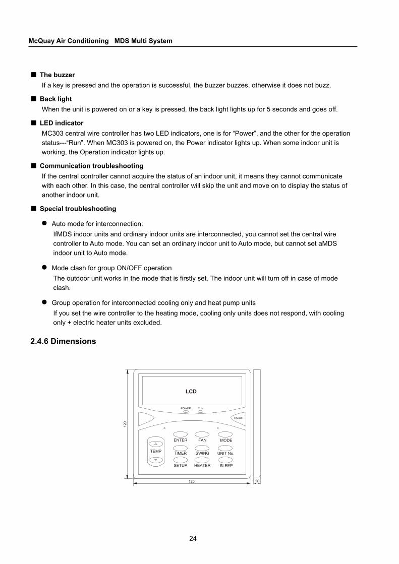
2.4.6 Dimensions
■
■
■
■
■●
●
●
25
CHAPTER 2Unit Control
Power Supply
ACDCAC/DC
ADAPTOR
TO CONTROL MODULE
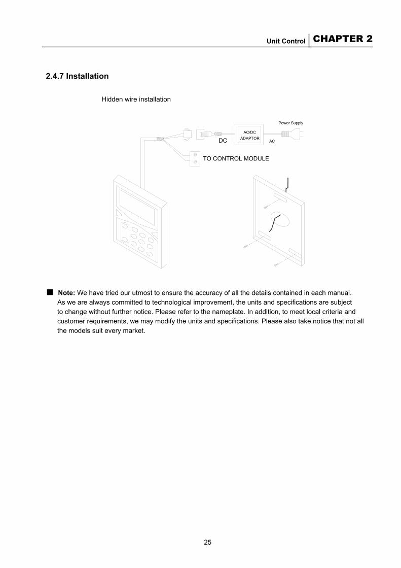
2.4.7 Installation
Hidden wire installation
■ Note: We have tried our utmost to ensure the accuracy of all the details contained in each manual. As we are always committed to technological improvement, the units and specifications are subject to change without further notice. Please refer to the nameplate. In addition, to meet local criteria and customer requirements, we may modify the units and specifications. Please also take notice that not all the models suit every market.
26
McQuay Air Conditioning MDS Multi System
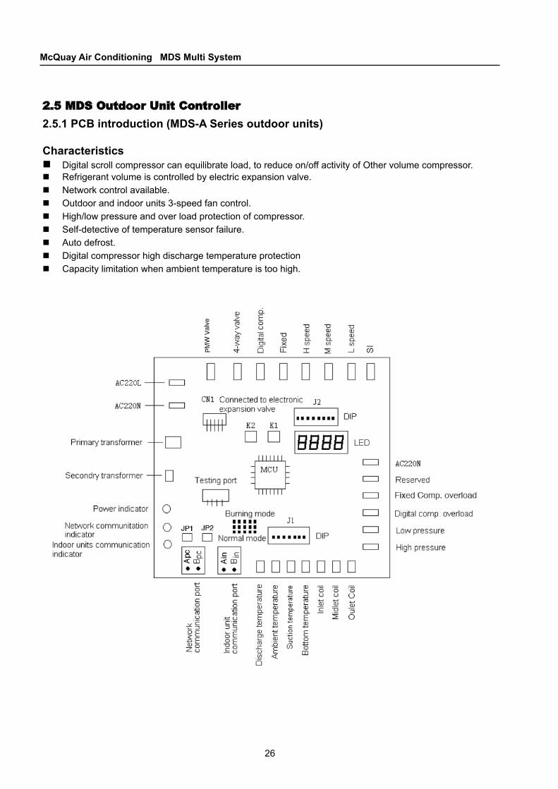
2.5 MDS Outdoor Unit Controller2.5.1 PCB introduction (MDS-A Series outdoor units) CharacteristicsDigital scroll compressor can equilibrate load, to reduce on/off activity of Other volume compressor. Refrigerant volume is controlled by electric expansion valve. Network control available. Outdoor and indoor units 3-speed fan control. High/low pressure and over load protection of compressor. Self-detective of temperature sensor failure. Auto defrost. Digital compressor high discharge temperature protection Capacity limitation when ambient temperature is too high.
27
CHAPTER 2Unit Control
PCB description■ Input ports The system has 5 testing ports: High pressure detective, low pressure detective, digital compressor
overload detective, Other compressor overload and reserved. ■ Output ports There are 9 output control ports: electronic expansion valve, PWM valve, 4-way valve, digital compressor
power source, other compressor power source, high fan speed, medium fan speed, low fan speed and reserved.
■ Sensor detective ports There are 7 sensor detective ports: digital compressor discharge temperature detective, ambient
temperature detective, return air temperature detective, compressor bottom temperature detective inlet coil temperature, mid coil temperature, outlet coil temperature detective. (Note: inlet and outlet is based on refrigerant flow direction.
■ Communication ports: There are two RS485 communication ports, one is connected to indoor units, and the other one is
connected to central controller (reserved now).
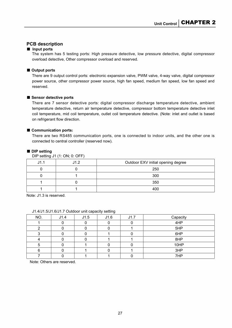
■ DIP settingDIP setting J1 (1: ON; 0: OFF)
J1.1 J1.2 Outdoor EXV initial opening degree
0 0 250
0 1 300
1 0 350
1 1 400Note: J1.3 is reserved.
J1.4/J1.5/J1.6/J1.7 Outdoor unit capacity settingNO. J1.4 J1.5 J1.6 J1.7 Capacity
1 0 0 0 0 4HP2 0 0 0 1 5HP3 0 0 1 0 6HP4 0 0 1 1 8HP5 0 1 0 0 10HP6 0 1 0 1 3HP7 0 1 1 0 7HP
Note: Others are reserved.
28
McQuay Air Conditioning MDS Multi System
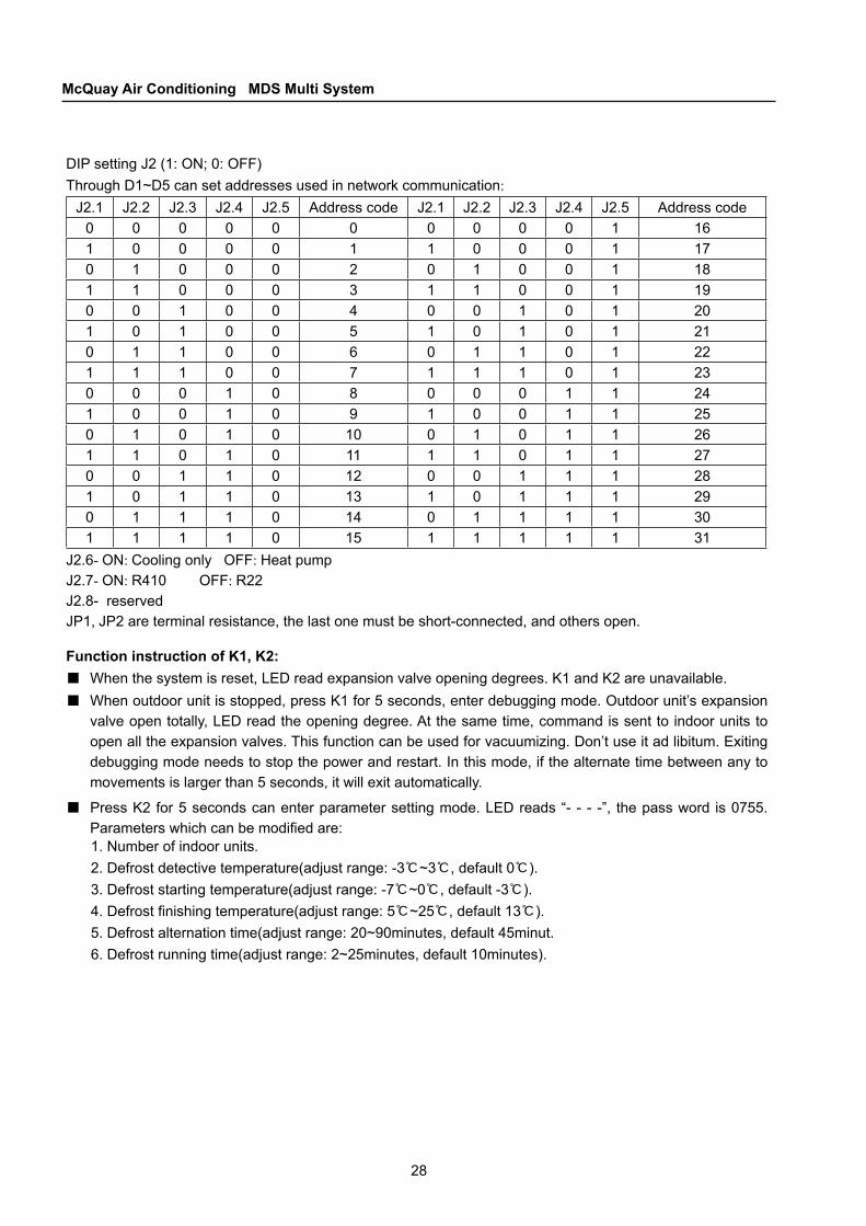
DIP setting J2 (1: ON; 0: OFF)Through D1~D5 can set addresses used in network communication:
J2.1 J2.2 J2.3 J2.4 J2.5 Address code J2.1 J2.2 J2.3 J2.4 J2.5 Address code0 0 0 0 0 0 0 0 0 0 1 161 0 0 0 0 1 1 0 0 0 1 170 1 0 0 0 2 0 1 0 0 1 181 1 0 0 0 3 1 1 0 0 1 190 0 1 0 0 4 0 0 1 0 1 201 0 1 0 0 5 1 0 1 0 1 210 1 1 0 0 6 0 1 1 0 1 221 1 1 0 0 7 1 1 1 0 1 230 0 0 1 0 8 0 0 0 1 1 241 0 0 1 0 9 1 0 0 1 1 250 1 0 1 0 10 0 1 0 1 1 261 1 0 1 0 11 1 1 0 1 1 270 0 1 1 0 12 0 0 1 1 1 281 0 1 1 0 13 1 0 1 1 1 290 1 1 1 0 14 0 1 1 1 1 301 1 1 1 0 15 1 1 1 1 1 31
J2.6- ON: Cooling only OFF: Heat pumpJ2.7- ON: R410 OFF: R22J2.8- reservedJP1, JP2 are terminal resistance, the last one must be short-connected, and others open.
Function instruction of K1, K2:■ When the system is reset, LED read expansion valve opening degrees. K1 and K2 are unavailable.■ When outdoor unit is stopped, press K1 for 5 seconds, enter debugging mode. Outdoor unit’s expansion
valve open totally, LED read the opening degree. At the same time, command is sent to indoor units to open all the expansion valves. This function can be used for vacuumizing. Don’t use it ad libitum. Exiting debugging mode needs to stop the power and restart. In this mode, if the alternate time between any to movements is larger than 5 seconds, it will exit automatically.
■ Press K2 for 5 seconds can enter parameter setting mode. LED reads “- - - -”, the pass word is 0755. Parameters which can be modified are:1. Number of indoor units. 2. Defrost detective temperature(adjust range: -3℃~3℃, default 0℃). 3. Defrost starting temperature(adjust range: -7℃~0℃, default -3℃).4. Defrost finishing temperature(adjust range: 5℃~25℃, default 13℃).5. Defrost alternation time(adjust range: 20~90minutes, default 45minut.6. Defrost running time(adjust range: 2~25minutes, default 10minutes).
29
CHAPTER 2Unit Control
■ Pass word input instruction:When LED read “- - - -“ press K1 in 5 seconds, LED will display 0~9. when the number is correct, press K2 to confirm input and the number will move to the left digit. After all the numbers are input correctly, LED read the number if indoor unit. Press K1 can modify it, and press K2 to confirm. If this parameter doesn’t need to be modified, press K2 move to the next parameter display. When all the parameters are finished, press K2 can exit parameter setting mode. In this mode, if the alternate time between any to operation is longer than 5 seconds, it will exit automatically.
Press K1 shortly, switch between current parameter display mode and setting mode.Press K2 shortly, LED show error code displayed by outdoor unit, including all the outdoor unit’s error (not including indoor units’ error). The modular memory can keep the latest 16 errors. Errors before 16 will be deleted. Display format is as “02F2”, the 2 digit on the left express error number. The 2 digit on the right express error type. The number of error which happened earliest is 01, the latest is 16.Press K1 and K2 at the same time for 5 seconds will delete all the error memory and go back to system parameter display mode.Error between outdoor and indoor units are expressed by “CX”, “X” is the number of indoor unit. When all the indoor units have error with outdoor unit, display “C-”.
●●
●
●
30
McQuay Air Conditioning MDS Multi System
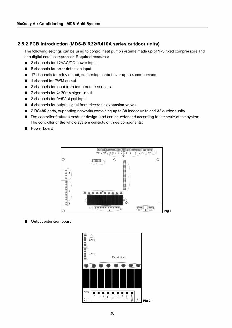
2.5.2 PCB introduction (MDS-B R22/R410A series outdoor units)The following settings can be used to control heat pump systems made up of 1~3 fixed compressors and one digital scroll compressor. Required resource:
2 channels for 12VAC/DC power input 8 channels for error detection input17 channels for relay output, supporting control over up to 4 compressors1 channel for PWM output2 channels for input from temperature sensors2 channels for 4~20mA signal input2 channels for 0~5V signal input4 channels for output signal from electronic expansion valves 2 RS485 ports, supporting networks containing up to 38 indoor units and 32 outdoor unitsThe controller features modular design, and can be extended according to the scale of the system. The controller of the whole system consists of three components:Power board
■■■■■■■■■■
■
Fig 1
Fig 2
Output extension board■
31
CHAPTER 2Unit Control
Power indicator Reset key
Fixing hole
Matching resistance for the central controller communication terminals
Connected to the central controller
Monitor communica-tion indicators
Connecting to the indoor unit
Connection socket
Terminal matching resistance for indoor unit communication
Indoor unit communica-tion indicators
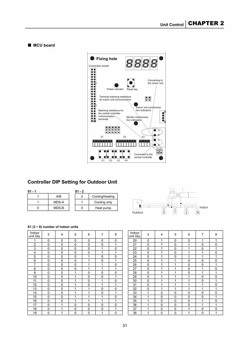
MCU board ■
Controller DIP Setting for Outdoor Unit
1 A/B
1 MDS-A
0 MDS-B
2 Cooling/heating
1 Cooling only
0 Heat pump
S1 - 1 S1 - 2
S1 (3 ~ 8) number of indoor units
Indoor unit Qty. 3 4 5 6 7 8
1 0 0 0 0 0 02 0 0 0 0 0 13 0 0 0 0 1 04 0 0 0 0 1 15 0 0 0 1 0 06 0 0 0 1 0 17 0 0 0 1 1 08 0 0 0 1 1 19 0 0 1 0 0 0
10 0 0 1 0 0 111 0 0 1 0 1 012 0 0 1 0 1 113 0 0 1 1 0 014 0 0 1 1 0 115 0 0 1 1 1 016 0 0 1 1 1 117 0 1 0 0 0 018 0 1 0 0 0 119 0 1 0 0 1 0
Indoor unit Qty. 3 4 5 6 7 8
20 0 1 0 0 1 121 0 1 0 1 0 022 0 1 0 1 0 123 0 1 0 1 1 024 0 1 0 1 1 125 0 1 1 0 0 026 0 1 1 0 0 127 0 1 1 0 1 028 0 1 1 0 1 129 0 1 1 1 0 030 0 1 1 1 0 131 0 1 1 1 1 032 0 1 1 1 1 133 1 0 0 0 0 034 1 0 0 0 0 135 1 0 0 0 1 036 1 0 0 0 1 137 1 0 0 1 0 038 1 0 0 1 0 1

32
McQuay Air Conditioning MDS Multi System
Master/slave
ReservedOutdoor unit capacity
Outdoor unit address Outdoor unit capacityCooling/heating only
Indoor unit
S2 - 1 S2 - 2 S2 - 3
1 Master/slave0 Slave module1 Master module
2 Reserved0 Standard unit1 -
3 Capacity0 (refer to S3)1 (refer to S3)
S2 (4 ~ 8) outdoor units addressAddress 4 5 6 7 8
0 0 0 0 0 01 0 0 0 0 12 0 0 0 1 03 0 0 0 1 14 0 0 1 0 05 0 0 1 0 16 0 0 1 1 07 0 0 1 1 18 0 1 0 0 09 0 1 0 0 1
10 0 1 0 1 011 0 1 0 1 112 0 1 1 0 013 0 1 1 0 114 0 1 1 1 015 0 1 1 1 1
Address 4 5 6 7 816 1 0 0 0 017 1 0 0 0 118 1 0 0 1 019 1 0 0 1 120 1 0 1 0 021 1 0 1 0 122 1 0 1 1 023 1 0 1 1 124 1 1 0 0 025 1 1 0 0 126 1 1 0 1 027 1 1 0 1 128 1 1 1 0 029 1 1 1 0 130 1 1 1 1 031 1 1 1 1 1
S2, S3 capacity of outdoor unit
S2 S3NO. 3 1 2 3 4 MDS-B
1 0 0 0 0 0 8HP1 0 0 0 0 1 10HP3 0 0 0 1 0 12HP4 0 0 0 1 1 15HP5 0 0 1 0 0 18HP6 0 0 1 0 1 20HP7 0 0 1 1 0 22HP8 0 0 1 1 1 24HP9 0 1 0 0 0 26HP
10 0 1 0 0 1 28HP11 0 1 0 1 0 30HP12 0 1 0 1 1 32HP
S2 S3NO. 3 1 2 3 4 MDS-B13 0 1 1 0 0 34HP14 0 1 1 0 1 36HP15 0 1 1 1 0 38HP16 0 1 1 1 1 40HP17 1 0 0 0 0 42HP18 1 0 0 0 1 44HP19 1 0 0 1 0 46HP20 1 0 0 1 1 48HP21 1 0 1 0 0 50HP22 1 0 1 0 1 14HP23 1 0 1 1 0 16HP
33
CHAPTER 2Unit Control
Monitoring
Monitoring
Master unit Slave unit
Indoor unit
System with a slave unit
Indoor unit
System without a slave unit
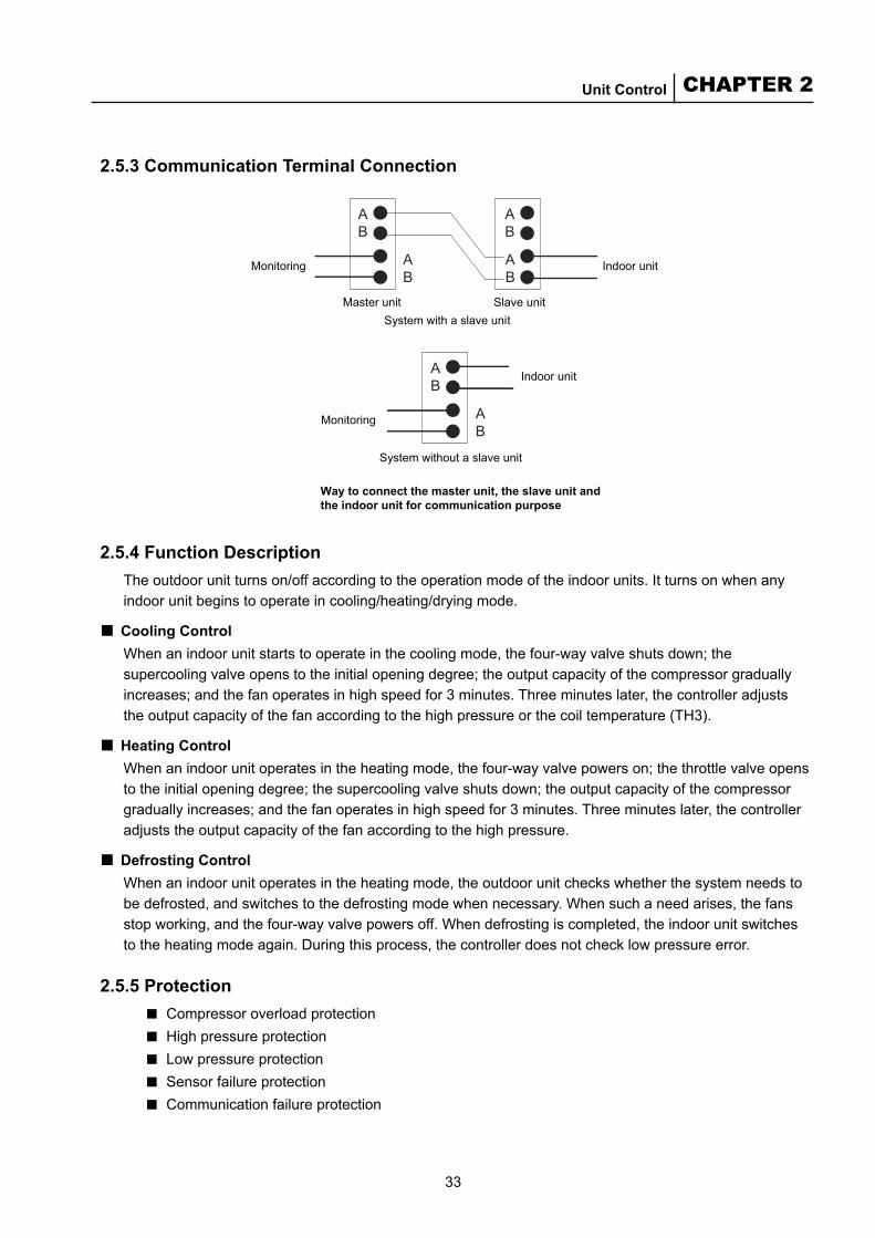
Way to connect the master unit, the slave unit and the indoor unit for communication purpose
2.5.3 Communication Terminal Connection
2.5.4 Function DescriptionThe outdoor unit turns on/off according to the operation mode of the indoor units. It turns on when any indoor unit begins to operate in cooling/heating/drying mode.
Cooling ControlWhen an indoor unit starts to operate in the cooling mode, the four-way valve shuts down; the supercooling valve opens to the initial opening degree; the output capacity of the compressor gradually increases; and the fan operates in high speed for 3 minutes. Three minutes later, the controller adjusts the output capacity of the fan according to the high pressure or the coil temperature (TH3).
Heating ControlWhen an indoor unit operates in the heating mode, the four-way valve powers on; the throttle valve opens to the initial opening degree; the supercooling valve shuts down; the output capacity of the compressor gradually increases; and the fan operates in high speed for 3 minutes. Three minutes later, the controller adjusts the output capacity of the fan according to the high pressure.
Defrosting Control When an indoor unit operates in the heating mode, the outdoor unit checks whether the system needs to be defrosted, and switches to the defrosting mode when necessary. When such a need arises, the fans stop working, and the four-way valve powers off. When defrosting is completed, the indoor unit switches to the heating mode again. During this process, the controller does not check low pressure error.
2.5.5 ProtectionCompressor overload protectionHigh pressure protectionLow pressure protectionSensor failure protectionCommunication failure protection
■
■
■
■■■■■

34
McQuay Air Conditioning MDS Multi System
Troubleshooting indoor unit communication failure:When some indoor units fail to communicate properly, the outdoor unit switches to protected operation mode. If some parameters put the unit at risk, the outdoor unit stops automatically.
Communication error protection (For MDS-A Series outdoor units only)The outdoor unit time checks indoor units. if some indoor units failed in communicating, the outdoor unit will consider it as disconnected, and displays communication error. Then the outdoor unit stops. After that, if outdoor unit checks again and finds no communication error, it will starts running.
All the units stop working when master/slave communication fails.The outdoor unit compressor stops working when the above failures take place. If the failure takes places 3 times within 1 hour, the system fails and requires a power-off reset to restart. When a sensor failure takes place, the system switches to protected operation mode according to the parameters detected.
●
●
●
Attached Table:■ Parameters code of outdoor unit(MDS-A Series outdoor units)When the unit is running, LED of outdoor unit will show operation parameters. It turns to be error code when system has failure.When LED display operation parameters, it will show the code numbers too(from 0 to 9). The number is shown for 0.5 seconds, and then parameter for 1.5 seconds.
1 TH1 Temperature of the discharged air2 TH 2/TH4 Inlet temperature of the heat exchanger 1/2 3 TH3 Middle part temperature of the heat exchanger 1 4 TH8 Outdoor environment temperature5 TH9 Temperature before supercooling6 TH10 Temperature after supercooling7 TH11 Outlet (returning to the compressor) temperature of the supercooling circuit8 TH12 Temperature of the inhaled air9 HS/LS Pressure of the discharged/inhaled air
10 HP High pressure switch
■ The following table lists the sequence of the cooling mode, and is applicable toMDS-B systems with HS and LS.
The numbers and parameters are as follow:NO. Parameter NO. Parameter
0 Digital comp. discharge temp. 5 Outdoor coil temperature (Midlet).1 Ambient temp. 6 Outdoor coil temperature (Outlet).2 Suction temperature. 7 Electronic expansion valve opening degree.3 Crankcase temperature. 8 PMW percentage4 Outdoor coil temperature (Inlet). 9 Control integral constant
LED read “PX—“ for 0.5 seconds and then read “YYYY” for 1.5 seconds.X is parameter number as follow
NO. Parameter NO. Parameter0 Number of indoor units. 5 Defrost running time.1 Defrost detective temperature setting. 6 Integral time.2 Defrost starting temperature setting. 7 Proportion constant.3 Defrost finishing temperature setting. 8 Integral constant.4 Defrost alternation time. 9 Controlling time.
35
CHAPTER 2Unit Control
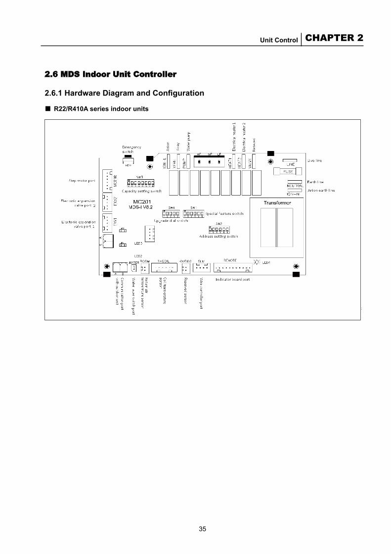
2.6 MDS Indoor Unit Controller
2.6.1 Hardware Diagram and Configuration
R22/R410A series indoor units■
36
McQuay Air Conditioning MDS Multi System
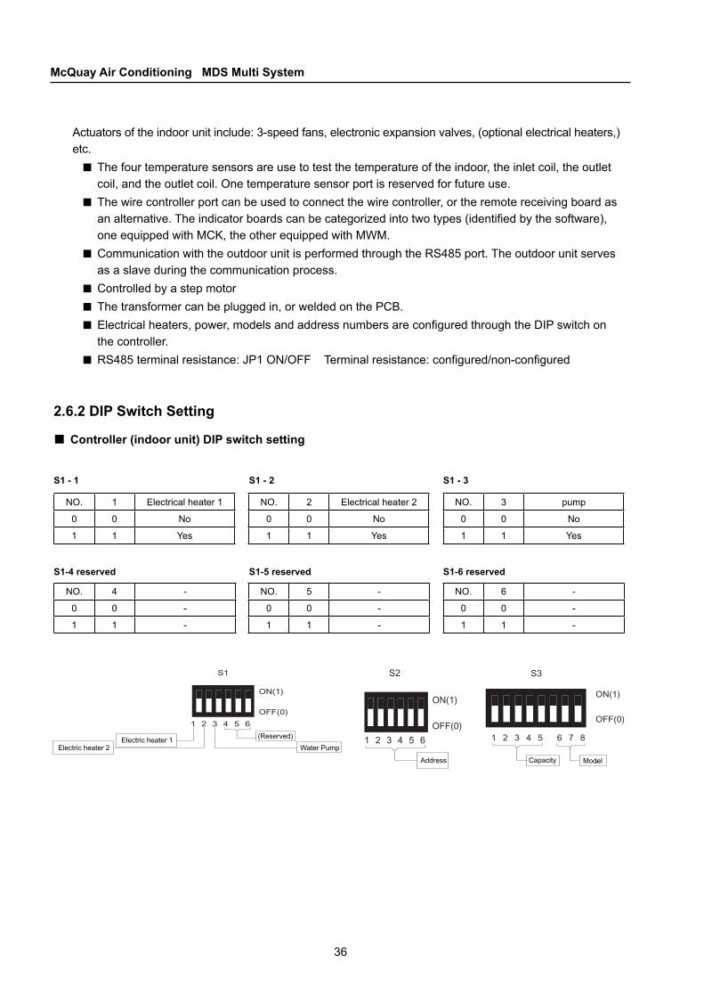
Actuators of the indoor unit include: 3-speed fans, electronic expansion valves, (optional electrical heaters,) etc.
The four temperature sensors are use to test the temperature of the indoor, the inlet coil, the outlet coil, and the outlet coil. One temperature sensor port is reserved for future use.The wire controller port can be used to connect the wire controller, or the remote receiving board as an alternative. The indicator boards can be categorized into two types (identified by the software), one equipped with MCK, the other equipped with MWM.Communication with the outdoor unit is performed through the RS485 port. The outdoor unit serves as a slave during the communication process.Controlled by a step motorThe transformer can be plugged in, or welded on the PCB.Electrical heaters, power, models and address numbers are configured through the DIP switch on the controller.RS485 terminal resistance: JP1 ON/OFF Terminal resistance: configured/non-configured
2.6.2 DIP Switch Setting
Controller (indoor unit) DIP switch setting
■
■
■
■■■
■
■
NO. 1 Electrical heater 1
0 0 No
1 1 Yes
NO. 2 Electrical heater 2
0 0 No
1 1 Yes
NO. 3 pump
0 0 No
1 1 Yes
NO. 4 -
0 0 -
1 1 -
NO. 5 -
0 0 -
1 1 -
NO. 6 -
0 0 -
1 1 -
S1-4 reserved S1-5 reserved S1-6 reserved
S1 - 1 S1 - 2 S1 - 3
Water Pump
Address Capacity Model
Electric heater 2Electric heater 1 (Reserved)

37
CHAPTER 2Unit Control
S2 (1 ~ 6) indoor unit address
Address 1 2 3 4 5 60 0 0 0 0 0 01 0 0 0 0 0 12 0 0 0 0 1 03 0 0 0 0 1 14 0 0 0 1 0 05 0 0 0 1 0 16 0 0 0 1 1 07 0 0 0 1 1 18 0 0 1 0 0 09 0 0 1 0 0 1
10 0 0 1 0 1 011 0 0 1 0 1 112 0 0 1 1 0 013 0 0 1 1 0 114 0 0 1 1 1 015 0 0 1 1 1 116 0 1 0 0 0 017 0 1 0 0 0 118 0 1 0 0 1 0
Address 1 2 3 4 5 619 0 1 0 0 1 120 0 1 0 1 0 021 0 1 0 1 0 122 0 1 0 1 1 023 0 1 0 1 1 124 0 1 1 0 0 025 0 1 1 0 0 126 0 1 1 0 1 027 0 1 1 0 1 128 0 1 1 1 0 029 0 1 1 1 0 130 0 1 1 1 1 031 0 1 1 1 1 132 1 0 0 0 0 033 1 0 0 0 0 134 1 0 0 0 1 035 1 0 0 0 1 136 1 0 0 1 0 037 1 0 0 1 0 1
S3 (1 ~ 5) indoor unit
NO. 1 2 3 4 5 Cooling capacity0 0 0 0 0 0 0.8 HP1 0 0 0 1 0 1.0 HP2 0 0 1 0 0 1.5 HP 3 0 0 1 1 0 1.8 HP4 0 1 0 0 0 2.0 HP5 0 1 0 1 0 2.5 HP6 0 1 1 0 0 3.0 HP7 0 1 1 1 0 4.0 HP8 1 0 0 0 0 5.0 HP9 1 0 0 1 0 6.0 HP
10 1 0 1 0 0 0.9 HP11 1 0 1 1 0 1.1 HP12 1 1 0 0 0 2.8 HP13 1 1 0 1 0 3.2 HP14 1 1 1 0 0 3.5 HP15 1 1 1 1 0 4.5 HP16 0 0 0 0 1 8.0 HP17 0 0 0 1 1 10.0 HP18 0 0 1 0 1 12.0 HP19 0 0 1 1 1 18.0 HP20 0 1 0 0 1 22.0 HP21 0 1 0 1 1 6.5HP22 0 1 1 0 1 24.0 HP
NO. 6 7 8 Model
0 0 0 0 MCC
1 0 0 1 MCK
2 0 1 0 MCM
3 0 1 1 MWM
4 1 0 0 MDB/MDBV
5 1 0 1 MDBX
6 1 1 0 -
7 1 1 1 -
38
McQuay Air Conditioning MDS Multi System
2.6.3 Description
Power On Setting
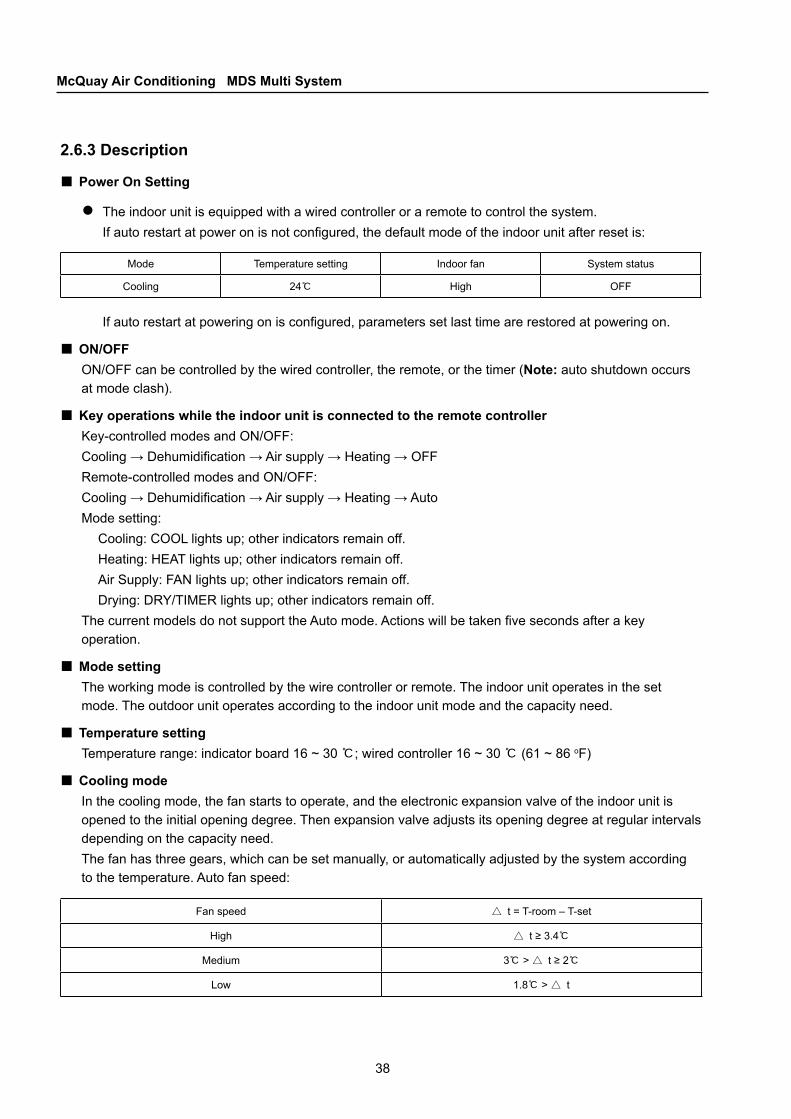
The indoor unit is equipped with a wired controller or a remote to control the system.If auto restart at power on is not configured, the default mode of the indoor unit after reset is:
■●
Mode Temperature setting Indoor fan System status
Cooling 24℃ High OFF
If auto restart at powering on is configured, parameters set last time are restored at powering on.
ON/OFFON/OFF can be controlled by the wired controller, the remote, or the timer (Note: auto shutdown occurs at mode clash).
Key operations while the indoor unit is connected to the remote controllerKey-controlled modes and ON/OFF:Cooling → Dehumidification → Air supply → Heating → OFFRemote-controlled modes and ON/OFF:Cooling → Dehumidification → Air supply → Heating → AutoMode setting:
Cooling: COOL lights up; other indicators remain off.Heating: HEAT lights up; other indicators remain off.Air Supply: FAN lights up; other indicators remain off.Drying: DRY/TIMER lights up; other indicators remain off.
The current models do not support the Auto mode. Actions will be taken five seconds after a key operation.
Mode settingThe working mode is controlled by the wire controller or remote. The indoor unit operates in the set mode. The outdoor unit operates according to the indoor unit mode and the capacity need.
Temperature settingTemperature range: indicator board 16 ~ 30 ℃; wired controller 16 ~ 30 ℃ (61 ~ 86 oF)
Cooling modeIn the cooling mode, the fan starts to operate, and the electronic expansion valve of the indoor unit is opened to the initial opening degree. Then expansion valve adjusts its opening degree at regular intervals depending on the capacity need. The fan has three gears, which can be set manually, or automatically adjusted by the system according to the temperature. Auto fan speed:
■
■
■
■
■
Fan speed △ t = T-room – T-set
High △ t ≥ 3.4℃
Medium 3℃ > △ t ≥ 2℃
Low 1.8℃ > △ t

39
CHAPTER 2Unit Control
Setting temperatureCooling mode
Heating mode
Operation time
Unit: hour
Dehumidification modeDehumidification is controlled in the same way as cooling control.
Heating modeIn the heating mode, the fan starts to operate, and the electronic expansion valve of the indoor unit is opened to the initial opening degree. Then expansion valve adjusts its opening degree at regular intervals depending on the capacity need. The fan has three gears, which can be set manually, or automatically adjusted by the system according to the temperature. Auto fan speed:
■
■
Fan speed △t = T-set – T-room
High △t ≥ 3.4℃
Medium 3℃ > △t ≥ 2℃
Low 1.8℃ > △t
In the cooling, heating or dehumidification mode, the outdoor unit adjusts the compressor output according to the capacity need of the indoor unit.
Air supply modeIn this mode, the indoor unit fan can be set to Low, medium or High speed. In the cooling/dehumidification mode, when the outdoor unit is heating, the electronic expansion valve of the indoor unit in air supply mode should be opened to a certain degree.When all the indoor unit fans are set to the air supply mode, the outdoor unit stops working. When the outdoor unit is heating, the indoor unit in air supply mode stops working. Meanwhile, the electronic expansion valve will be closed.
Sleeping
■
■
This feature increases or decreases the set temperature as the time goes by. It is only available for the heating and cooling mode. In any other mode, this feature cannot be activated, and the timer will be reset. Switching between the cooling and the heating mode will reset the sleep time.
40
McQuay Air Conditioning MDS Multi System
Singel electric heater Double electric heaters
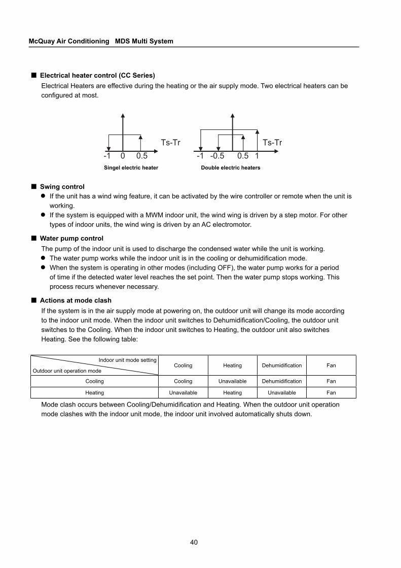
Electrical heater control (CC Series)Electrical Heaters are effective during the heating or the air supply mode. Two electrical heaters can be configured at most.
■
Swing controlIf the unit has a wind wing feature, it can be activated by the wire controller or remote when the unit is working.If the system is equipped with a MWM indoor unit, the wind wing is driven by a step motor. For other types of indoor units, the wind wing is driven by an AC electromotor.
Water pump controlThe pump of the indoor unit is used to discharge the condensed water while the unit is working.
The water pump works while the indoor unit is in the cooling or dehumidification mode.When the system is operating in other modes (including OFF), the water pump works for a period of time if the detected water level reaches the set point. Then the water pump stops working. This process recurs whenever necessary.
Actions at mode clashIf the system is in the air supply mode at powering on, the outdoor unit will change its mode according to the indoor unit mode. When the indoor unit switches to Dehumidification/Cooling, the outdoor unit switches to the Cooling. When the indoor unit switches to Heating, the outdoor unit also switches Heating. See the following table:
■●
●
■
●●
■
Indoor unit mode setting
Outdoor unit operation modeCooling Heating Dehumidification Fan
Cooling Cooling Unavailable Dehumidification Fan
Heating Unavailable Heating Unavailable Fan
Mode clash occurs between Cooling/Dehumidification and Heating. When the outdoor unit operation mode clashes with the indoor unit mode, the indoor unit involved automatically shuts down.
41
CHAPTER 2Unit Control
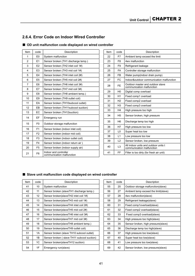
2.6.4. Error Code on Indoor Wired Controller
OD unit malfunction code displayed on wired controller■Item code Description
1 E0 System malfunction
2 E1 Sensor broken (TH1 discharge temp.)
3 E2 Sensor broken (TH2 inlet coil 1#)
4 E3 Sensor broken (TH3 mid coil 1#)
5 E4 Sensor broken (TH4 inlet coil 2#)
6 E5 Sensor broken (TH5 mid coil 2#)
7 E6 Sensor broken (TH6 inlet coil 3#)
8 E7 Sensor broken (TH7 mid coil 3#)
9 E8 Sensor broken (TH8 ambient temp.)
10 E9 Sensor broken (TH9 outlet coil)
11 EA Sensor broken (TH10subcool outlet)
12 EB Sensor broken (TH11subcool suction)
13 EC Sensor broken (TH12suction)
14 EF Emergency run
15 F0 Outdoor storage malfunction
16 F1 Sensor broken (indoor inlet coil)
17 F2 Sensor broken (indoor mid coil)
18 F3 Sensor broken (indoor outlet coil)
19 F4 Sensor broken (indoor return air )
20 F5 Sensor broken (indoor supply air)
21 F6 Indoor and controller communication malfunction
Slave unit malfunction code displayed on wired controller■
Item code Description
22 F7 Ambient temp exceed the limit
23 F8 4wv malfunction
24 F9 Refrigerant leakage
25 FA Controller storage malfunction
26 FB Water pump(indoor drain pump)
27 FC Indoor&outdoor communication malfunction
28 FE Outdoor master and outdoor slave communication malfunction
29 H0 Digital comp overload
30 H1 Fixed comp1 overload
31 H2 Fixed comp2 overload
32 H3 Fixed comp3 overload
33 H4 High pressure too high
34 H5 Sensor broken, high pressure
35 H6 Discharge temp too high
36 H7 High pressure too low
37 L0 Super heat too low
38 L1 Low pressure too low
39 L2 Sensor broken, low pressure
40 L3 All indoor units and outdoor units t communication malfunction
41 FF Filter is too dirty (for fresh air unit)
Item code Description
41 10 System malfunction
42 11 Sensor broken (slaveTH1 discharge temp.)
43 12 Sensor broken(slaveTH2 inlet coil 1#)
44 13 Sensor broken(slaveTH3 mid coil 1#)
45 14 Sensor broken(slaveTH4 inlet coil 2#)
46 15 Sensor broken(slaveTH5 mid coil 2#)
47 16 Sensor broken(slaveTH6 inlet coil 3#)
48 17 Sensor broken(slaveTH7 mid coil 3#)
49 18 Sensor broken(slaveTH8 ambient temp.)
50 19 Sensor broken(slaveTH9 outlet coil)
51 1A Sensor broken (slave TH10 subcool outlet)
52 1B Sensor broken ( slave TH11 subcool suction)
53 1C Sensor broken(slaveTH12 suction)
54 1F Emergency run(slave)
Item code Description
55 20 Outdoor storage malfunction(slave)
56 27 Ambient temp exceed the limit(slave)
57 28 4wv malfunction(slave)
58 29 Refrigerant leakage(slave)
60 31 Fixed comp1overload(slave)
61 32 Fixed comp2 overload(slave)
62 33 Fixed comp3 overload(slave)
63 34 High pressure too high(slave)
64 35 Sensor broken, high pressure(slave)
65 36 Discharge temp too high(slave)
66 37 High pressure too low(slave)
67 40 Super heat too low(slave)
68 41 Low pressure too low(slave)
69 42 Sensor broken, low pressure(slave)

42
McQuay Air Conditioning MDS Multi System
2.6.5 Error Indicated by Indicator BoardFailure type Heat Sleep/Fan Time/Dry
Indoor unit temperature sensor failure Off Off Blink
Indoor unit pump failure Off Blink Off
Communication failure between the indoor and outdoor units Blink Off Off
Outdoor unit temperature sensor failure Off Blink Blink
Compressor overload (including digital and fixed scroll compressors) Blink Blink Off
Pressure is too high or too low Blink Off Blink
Outdoor unit pressure sensor failure Blink Blink On
System failure Blink Blink Blink
Other failures Blink On On
Notes:
Mode clash is not a kind of failure. Instead, it is a kind of operation restriction. Therefore, at mode clash, the indoor unit shuts down, but the alarm does not go off.When communication failure occurs between the indoor and outdoor units, the indicator only indicates failures of the indoor unit.Simplified failure indication of indicator board
■
■
■
2.6.6 Error Code Displayed byMDS Outdoor Unit LED
■ Error Code Displayed by MDS-A Series Outdoor Unit LED:NO. Error code Error description Result
1 E0 Sensor broken (Outdoor discharge temperature) Unit stops.
2 E1 Sensor broken (Outdoor ambient temperature) Fans run high speed when outdoor unit cooling.System take it as 0℃ when outdoor unit heating.
3 E2 Sensor broken (Outdoor suction temperature). Alarm
4 E3 Sensor broken (Crankcase temperature). Ignore(doesn’t effect system operation)
5 E4 Sensor broken (Outdoor coil inlet). Alarm when cooling.
6 E5 Sensor broken (Outdoor coil midlet).Fans run high speed when outdoor unit cooling.In heating mode, defrost period is 1 hour, 5 minutes is each time.
7 E6 Sensor broken (Outdoor coil outlet). As same as E4
8 E7 Discharge temp. is too high(>130) Unit stops. It can only be restarted after system power off.
9 E8 System failure Unit stops. It can only be restarted after system power off.
10 H1 Compressor high is too high Compressors stop for 3 minutes to protect system. If H1 comes up 3 times in 1 hour, E8 error works.
11 H2 Digital compressor overload As same as H1
12 H3 Fixed compressor overload As same as H1
13 L1 Compressor low pressure is too low As same as H1
14 C- all the indoor units and outdoor unit communication malfunction. Unit stops.
15 CX X# indoor unit and outdoor unit communication malfunction. Unit stops.
Notice: “X” means the address code of the indoor unit.

43
CHAPTER 2Unit Control
■ Error Code Displayed by MDS Outdoor Unit LED (MDS-B R22/R410A Series )
Error code Symptom Result
EC00 Communication malfunction between 0# indoor/outdoor units
Ignores the indoor unit and switches to protected operation mode
ECXX Communication malfunction between XX# indoor/outdoor units
Ignores the indoor unit and switches to protected operation mode
ER48 Digital compressor overload Stops working
ER49 No. 1 fixed compressor overload Stops working
ER50 No. 2 fixed compressor overload Stops working
ER51 No. 3 fixed compressor overload Stops working
ER52 High pressure is too high Stops working
ER53 Low pressure is too low Stops working
ER54 Memory failure (outdoor unit) Works according to the default parameters
ER55 System malfunction Stops working
ER56 Discharge temperature is too high. Stops working
ER57 Communication failure between the indoor and outdoor units Switches to protected operation mode
ER58 Four-way valve malfunction Currently unavailable
ER59 The environment temperature exceeds the operational temperature range. Stops working
ER60 Emergent operation 30 minutes each time
ER61 Protection against a too low superheating degree Stops working
ER62 Refrigerant leakage Currently unavailable
ER63 Slave unit communication malfunction The master unit works properly, but the slave unit stops working.
ER64 TH1 broken/shorted circuit ( discharged air temperature) Stops working
ER65 TH2 broken/shorted circuit (1# inlet coil)The broken/shorted circuit does not raise the alarm if it makes no change on the current operation control logic.
ER66 TH3 broken/shorted circuit (1# midlet coil) Ditto the above.
ER67 TH4 broken/shorted circuit (2# inlet coil) Ditto the above.
ER68 TH5 broken/shorted circuit (2# midlet coil) Ditto the above.
ER69 TH6 broken/shorted circuit (3# inlet coil) Ditto the above.
ER70 TH7 broken/shorted circuit (3# midlet coil) Ditto the above.
ER71 TH8 broken/shorted circuit (environment) Ditto the above.
ER72 TH9 broken/shorted circuit (general outlet coil) Ditto the above.
ER73 TH10 broken/shorted circuit (supercooling inlet) Ditto the above.
ER74 TH11 broken/shorted circuit (supercooling outlet) Ditto the above.
ER75 TH12 broken/shorted circuit (return air) Ditto the above.
ER76 High pressure sensor malfunction Stops working
ER77 Low pressure sensor malfunction Stops working
ER78 Communication malfunction exist among all the indoor and outdoor units. Stops working
44
McQuay Air Conditioning MDS Multi System
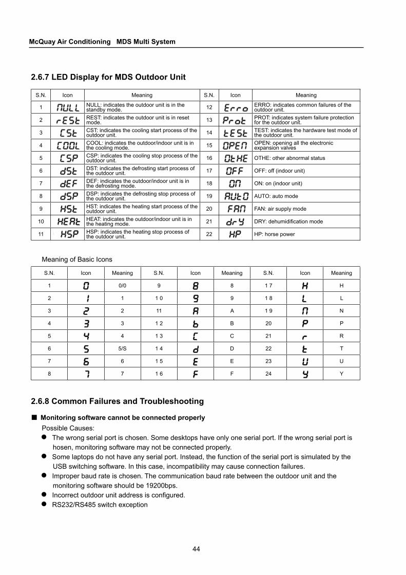
2.6.7 LED Display for MDS Outdoor Unit
S.N. Icon Meaning S.N. Icon Meaning
1 NULL: indicates the outdoor unit is in the standby mode. 12 ERRO: indicates common failures of the
outdoor unit.
2 REST: indicates the outdoor unit is in reset mode. 13 PROT: indicates system failure protection
for the outdoor unit.
3 CST: indicates the cooling start process of the outdoor unit. 14 TEST: indicates the hardware test mode of
the outdoor unit.
4 COOL: indicates the outdoor/indoor unit is in the cooling mode. 15 OPEN: opening all the electronic
expansion valves
5 CSP: indicates the cooling stop process of the outdoor unit. 16 OTHE: other abnormal status
6 DST: indicates the defrosting start process of the outdoor unit. 17 OFF: off (indoor unit)
7 DEF: indicates the outdoor/indoor unit is in the defrosting mode. 18 ON: on (indoor unit)
8 DSP: indicates the defrosting stop process of the outdoor unit. 19 AUTO: auto mode
9 HST: indicates the heating start process of the outdoor unit. 20 FAN: air supply mode
10 HEAT: indicates the outdoor/indoor unit is in the heating mode. 21 DRY: dehumidification mode
11 HSP: indicates the heating stop process of the outdoor unit. 22 HP: horse power
Meaning of Basic Icons
S.N. Icon Meaning S.N. Icon Meaning S.N. Icon Meaning
1 0/0 9 8 1 7 H
2 1 1 0 9 1 8 L
3 2 11 A 1 9 N
4 3 1 2 B 20 P
5 4 1 3 C 21 R
6 5/S 1 4 D 22 T
7 6 1 5 E 23 U
8 7 1 6 F 24 Y
2.6.8 Common Failures and Troubleshooting
Monitoring software cannot be connected properlyPossible Causes:
The wrong serial port is chosen. Some desktops have only one serial port. If the wrong serial port is hosen, monitoring software may not be connected properly.Some laptops do not have any serial port. Instead, the function of the serial port is simulated by the USB switching software. In this case, incompatibility may cause connection failures.Improper baud rate is chosen. The communication baud rate between the outdoor unit and the monitoring software should be 19200bps.Incorrect outdoor unit address is configured.RS232/RS485 switch exception
■
●
●
●
●●

45
CHAPTER 2Unit Control
Communication failure between the indoor and outdoor unitsPossible Causes:
Communication wires are connected in the wrong wayThe indoor unit addresses are not correctly configured (repetition or missing)The indoor unit trip or powers off
Other failures that may occur in both the indoor and outdoor units:Communication IC is damagedInterference from large power cables nearbyThe program version is not compatibleThe line is too long (should not exceed 1000m)Communication wires are connected in the wrong wayImproper network structure weakens the signal
TripThe power supply is not properly connectedMCU board is being burned
Other considerations Set the DIP switches before powering on the systemConnect the communication wires before powering on the system. To prevent damage to the communication IC, hot plug/unplug is not allowed.Do not turn on the compressor or any large power equipment while testing the hardware Pay attention to the electrodes while connecting the pressure sensorsWhile plugging in the modules, check that the pins and pinholes are correctly matched. Any improper plugging may cause fatal damage to the controller.The DIP switch must match the unit model; otherwise it may generate incorrect output.Perform other operations according to the user guide or installation manual.
■
●●●
●●●●●●
■
■●●
●●●
●●
Symptom analyses Solution
Compressor stop and fan work normally
Indoor temperature is higher (heating) or lower (cooling) than setting temperature Re – set up the temperature
When heating and defrost mode, indoor unit is just running Waiting for 10minutes
Units do not work
Power is not on Check and connect the power
Set up the re-start function Wait or cancel timer On
Fuse broken in main power supply Replace the fuse
Cooling or heating not enough or too much Air filter too dirty Clean or replace the filter
Return air barrier Remove the barrier
Remote controller unreadable Low battery Replace the battery
Wrong installation of battery Install properly
Condensing water in front panel Humidity too high Dehumidify
Setting temperature too low Set up the higher indoor temperature
If the followings unit malfunction occurred, please follow the below simple checking step to fix :■
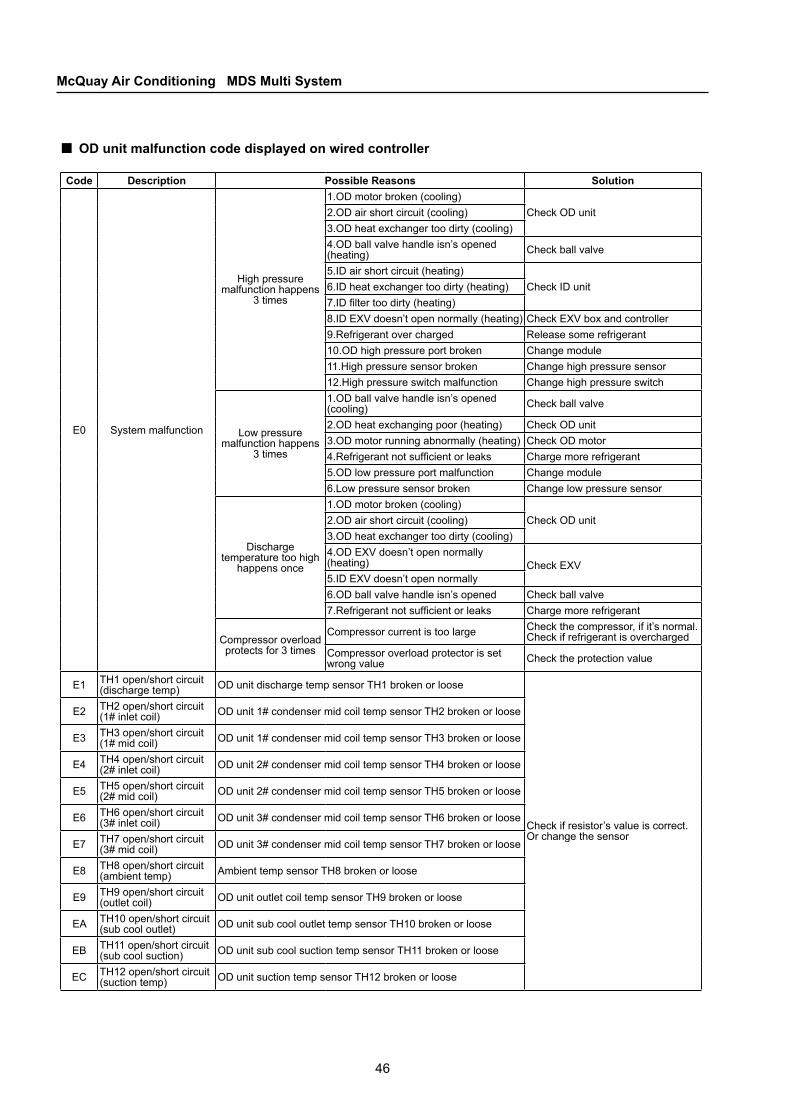
46
McQuay Air Conditioning MDS Multi System
OD unit malfunction code displayed on wired controller■Code Description Possible Reasons Solution
E0 System malfunction
High pressure malfunction happens
3 times
1.OD motor broken (cooling)Check OD unit2.OD air short circuit (cooling)
3.OD heat exchanger too dirty (cooling)4.OD ball valve handle isn’s opened (heating) Check ball valve
5.ID air short circuit (heating)Check ID unit6.ID heat exchanger too dirty (heating)
7.ID filter too dirty (heating)8.ID EXV doesn’t open normally (heating) Check EXV box and controller9.Refrigerant over charged Release some refrigerant10.OD high pressure port broken Change module11.High pressure sensor broken Change high pressure sensor12.High pressure switch malfunction Change high pressure switch
Low pressure malfunction happens
3 times
1.OD ball valve handle isn’s opened (cooling) Check ball valve
2.OD heat exchanging poor (heating) Check OD unit3.OD motor running abnormally (heating) Check OD motor4.Refrigerant not sufficient or leaks Charge more refrigerant5.OD low pressure port malfunction Change module6.Low pressure sensor broken Change low pressure sensor
Discharge temperature too high
happens once
1.OD motor broken (cooling)Check OD unit2.OD air short circuit (cooling)
3.OD heat exchanger too dirty (cooling)4.OD EXV doesn’t open normally (heating) Check EXV5.ID EXV doesn’t open normally6.OD ball valve handle isn’s opened Check ball valve7.Refrigerant not sufficient or leaks Charge more refrigerant
Compressor overload protects for 3 times
Compressor current is too large Check the compressor, if it’s normal. Check if refrigerant is overcharged
Compressor overload protector is set wrong value Check the protection value
E1 TH1 open/short circuit (discharge temp) OD unit discharge temp sensor TH1 broken or loose
Check if resistor’s value is correct. Or change the sensor
E2 TH2 open/short circuit (1# inlet coil) OD unit 1# condenser mid coil temp sensor TH2 broken or loose
E3 TH3 open/short circuit (1# mid coil) OD unit 1# condenser mid coil temp sensor TH3 broken or loose
E4 TH4 open/short circuit (2# inlet coil) OD unit 2# condenser mid coil temp sensor TH4 broken or loose
E5 TH5 open/short circuit (2# mid coil) OD unit 2# condenser mid coil temp sensor TH5 broken or loose
E6 TH6 open/short circuit (3# inlet coil) OD unit 3# condenser mid coil temp sensor TH6 broken or loose
E7 TH7 open/short circuit (3# mid coil) OD unit 3# condenser mid coil temp sensor TH7 broken or loose
E8 TH8 open/short circuit (ambient temp) Ambient temp sensor TH8 broken or loose
E9 TH9 open/short circuit (outlet coil) OD unit outlet coil temp sensor TH9 broken or loose
EA TH10 open/short circuit (sub cool outlet) OD unit sub cool outlet temp sensor TH10 broken or loose
EB TH11 open/short circuit (sub cool suction) OD unit sub cool suction temp sensor TH11 broken or loose
EC TH12 open/short circuit (suction temp) OD unit suction temp sensor TH12 broken or loose

47
CHAPTER 2Unit Control
Code Description Possible Reasons Solution
EF Emergency run
While communication malfunction happens to parts of ID units: Find out failed ID untis and solve it.
Refrigerant overcharge. Solve TH12 malfunction.1.Super heaing temperature <1℃ for 15 minutes
2.TH2 malfunction
F0 OD unit storage malfunction1.OD unit module failed reading the data from the chip while power on Reset OD unit.
2.OD unit’s module broken Change the module.
F1 ID unit inlet temp sensor malfunction ID unit inlet sensor(Tin) broken or loose
Check if resistor’s value is correct. Or change the sensor
F2 ID unit mid coil temp sensor malfunction ID unit mid coil sensor(Tmid) broken or loose
F3 ID unit outlet temp sensor malfunction ID unit outlet sensor(Tout) broken or loose
F4 ID unit return air temp sensor malfunction ID unit return air temp sensor(Troom) broken or loose
F5 ID unit supply air temp sensor malfunction ID unit supply air temp sensor(Troom) broken or loose
F6 communication malfunction1.Wired controller is loose or unconnected Check communication wire2.Wired controller broken Change wired controller3.TH12 malfunction Change ID unit module
F7 Ambient temperature out of limit
1.Ambient temperature out of limitAvoid to protect the unit a.Cooling temperature range:0~43℃
b.Heating temperature range:-15~30℃2.OD unit’s air flow short circuit
Check the OD unit a.Makes OD units working temperature higher untill out of limit b.Makes OD units working temperature lower untill out of limit
F8 4 way valve malfunction RemaindF9 Refrigerant leakage Remaind
FA Wired controller momery malfunction
1.Data reading failed when power on Reset through the wired controller2.Chip broken Change controller
FB Pump malfunciton1.Water level switch broken Change water level switch2.Pump broken Change pump
FC ID and OD communication malfunction
1.Communication wire between ID units loose or broken
Check wire connection2.AB line connected contrarily3.Communication wire is too long(over 1000m)4.OD unit power off Check power supply5.ID/OD units jumper set wrong
Check the module6.The last ID unit’s terminal resistance not short circuit.7.ID&OD module version not compatible8.ID/OD module abnormal
FE OD master and slave communication malfunction
1.AB line connected contrarilyCheck wire connection
2.Communication wire loose or broken
3.Slave unit’s jumper set wrong Check jumper. All the jumper are same with master unit’s except SW2.1.
OD unit malfunction code displayed on wired controller■
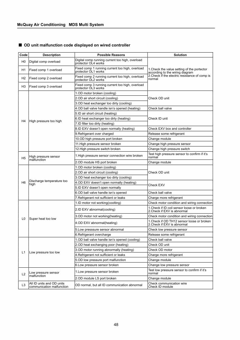
48
McQuay Air Conditioning MDS Multi System
Code Description Possible Reasons Solution
H0 Digital comp overload Digital comp running current too high, overload protector OL4 works
1.Check the value setting of the portector according to the wiring diagram 2.Check if the electric resistance of comp is normal
H1 Fixed comp 1 overload Fixed comp 1 running current too high, overload protector OL1 works
H2 Fixed comp 2 overload Fixed comp 2 running current too high, overload protector OL2 works
H3 Fixed comp 3 overload Fixed comp 3 running current too high, overload protector OL3 works
H4 High pressure too high
1.OD motor broken (cooling)Check OD unit2.OD air short circuit (cooling)
3.OD heat exchanger too dirty (cooling)4.OD ball valve handle isn’s opened (heating) Check ball valve5.ID air short circuit (heating)
Check ID unit6.ID heat exchanger too dirty (heating)7.ID filter too dirty (heating)8.ID EXV doesn’t open normally (heating) Check EXV box and controller9.Refrigerant over charged Release some refrigerant10.OD high pressure port broken Change module11.High pressure sensor broken Change high pressure sensor12.High pressure switch broken Change high pressure switch
H5 High pressure sensor malfunction
1.High pressure sensor connection wire broken Test high pressure sensor to confirm if it’s normal
2.OD module HS port broken Change module
H6 Discharge temperature too high
1.OD motor broken (cooling)Check OD unit2.OD air short circuit (cooling)
3.OD heat exchanger too dirty (cooling)4.OD EXV doesn’t open normally (heating)
Check EXV5.ID EXV doesn’t open normally6.OD ball valve handle isn’s opened Check ball valve7.Refrigerant not sufficient or leaks Charge more refrigerant
L0 Super heat too low
1.ID motor not working(coolting) Check motor condition and wiring connection
2.ID EXV abnormal(cooling) 1.Check if ID coil sensor loose or broken 2.Check if EXV is abnormal
3.OD motor not working(heating) Check motor condition and wiring connection
4.OD EXV abnormal(heating) 1.Check if OD TH12 sensor loose or broken 2.Check if EXV is abnormal
5.Low presssure sensor abnormal Check low pressure sensor6.Refrigerant overcharge Release some refrigerant
L1 Low pressure too low
1.OD ball valve handle isn’s opened (cooling) Check ball valve2.OD heat exchanging poor (heating) Check OD unit3.OD motor running abnormally (heating) Check OD motor4.Refrigerant not sufficient or leaks Charge more refrigerant5.OD low pressure port malfunction Change module6.Low pressure sensor broken Change low pressure sensor
L2 Low pressure sensor malfunction
1.Low pressure sensor broken Test low pressure sensor to confirm if it’s normal
2.OD module LS port broken Change module
L3 All ID units and OD units communication malfunction OD normal, but all ID communication abnormal Check communication wire
Check ID module
OD unit malfunction code displayed on wired controller■
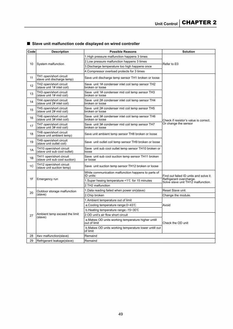
49
CHAPTER 2Unit Control
Code Description Possible Reasons Solution
10 System malfunction
1.High pressure malfunction happens 3 times
Refer to E02.Low pressure malfunction happens 3 times3.Discharge temperature too high happens once4.Compressor overload protects for 3 times
11 TH1 open/short circuit slave unit discharge temp) Save unit discharge temp sensor TH1 broken or loose
Check if resistor’s value is correct. Or change the sensor
12 TH2 open/short circuit (slave unit 1# inlet coil)
Save unit 1# condenser inlet coil temp sensor TH2 broken or loose
13 TH3 open/short circuit (slave unit 1# mid coil)
Save unit 1# condenser mid coil temp sensor TH3 broken or loose
14 TH4 open/short circuit (slave unit 2# inlet coil)
Save unit 2# condenser inlet coil temp sensor TH4 broken or loose
15 TH5 open/short circuit (slave unit 2# mid coil)
Save unit 2# condenser mid coil temp sensor TH5 broken or loose
16 TH6 open/short circuit (slave unit 3# inlet coil)
Save unit 3# condenser inlet coil temp sensor TH6 broken or loose
17 TH7 open/short circuit (slave unit 3# mid coil)
Save unit 3# condenser mid coil temp sensor TH7 broken or loose
18 TH8 open/short circuit (slave unit ambient temp) Save unit ambient temp sensor TH8 broken or loose
19 TH9 open/short circuit (slave unit outlet coil) Save unit outlet coil temp sensor TH9 broken or loose
1A TH10 open/short circuit (slave unit sub cool outlet)
Save unit sub cool outlet temp sensor TH10 broken or loose
1B TH11 open/short circuit (slave unit sub cool suction)
Save unit sub cool suction temp sensor TH11 broken or loose
1C TH12 open/short circuit (slave unit suction temp) Save unit suction temp sensor TH12 broken or loose
1F Emergency run
While communication malfunction happens to parts of ID units: Find out failed ID untis and solve it.
Refrigerant overcharge. Solve slave unit TH12 malfunction.1.Super heaing temperature <1℃ for 15 minutes
2.TH2 malfunction
20 Outdoor storage malfunction (slave)
1.Data reading failed when power on(slave) Reset Slave unit.2.Chip broken Change the module.
27 Ambient temp exceed the limit (slave)
1.Ambient temperature out of limitAvoid a.Cooling temperature range:0~43℃
b.Heating temperature range:-15~30℃2.OD unit’s air flow short circuit
Check the OD unit a.Makes OD units working temperature higher untill out of limit b.Makes OD units working temperature lower untill out of limit
28 4wv malfunction(slave) Remaind29 Refrigerant leakage(slave) Remaind
Slave unit malfunction code displayed on wired controller■
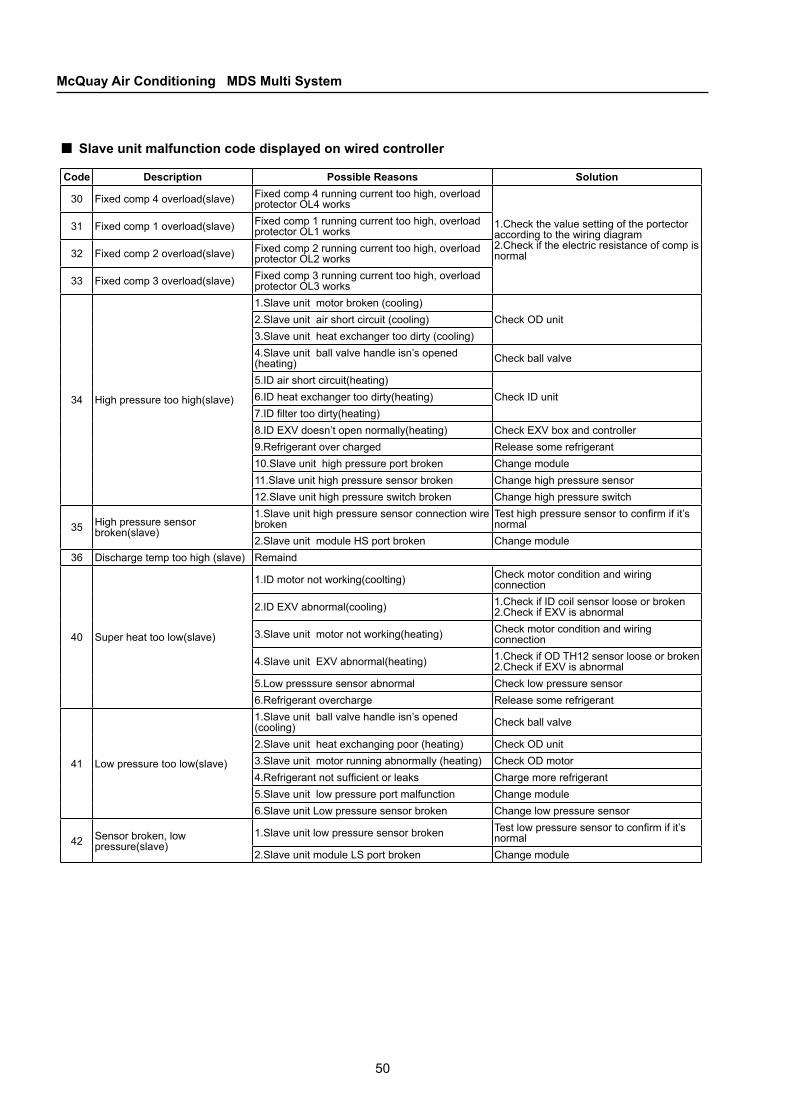
50
McQuay Air Conditioning MDS Multi System
Code Description Possible Reasons Solution
30 Fixed comp 4 overload(slave) Fixed comp 4 running current too high, overload protector OL4 works
1.Check the value setting of the portector according to the wiring diagram 2.Check if the electric resistance of comp is normal
31 Fixed comp 1 overload(slave) Fixed comp 1 running current too high, overload protector OL1 works
32 Fixed comp 2 overload(slave) Fixed comp 2 running current too high, overload protector OL2 works
33 Fixed comp 3 overload(slave) Fixed comp 3 running current too high, overload protector OL3 works
34 High pressure too high(slave)
1.Slave unit motor broken (cooling)Check OD unit2.Slave unit air short circuit (cooling)
3.Slave unit heat exchanger too dirty (cooling)4.Slave unit ball valve handle isn’s opened (heating) Check ball valve
5.ID air short circuit(heating)Check ID unit6.ID heat exchanger too dirty(heating)
7.ID filter too dirty(heating)8.ID EXV doesn’t open normally(heating) Check EXV box and controller9.Refrigerant over charged Release some refrigerant10.Slave unit high pressure port broken Change module11.Slave unit high pressure sensor broken Change high pressure sensor12.Slave unit high pressure switch broken Change high pressure switch
35 High pressure sensor broken(slave)
1.Slave unit high pressure sensor connection wire broken
Test high pressure sensor to confirm if it’s normal
2.Slave unit module HS port broken Change module36 Discharge temp too high (slave) Remaind
40 Super heat too low(slave)
1.ID motor not working(coolting) Check motor condition and wiring connection
2.ID EXV abnormal(cooling) 1.Check if ID coil sensor loose or broken 2.Check if EXV is abnormal
3.Slave unit motor not working(heating) Check motor condition and wiring connection
4.Slave unit EXV abnormal(heating) 1.Check if OD TH12 sensor loose or broken 2.Check if EXV is abnormal
5.Low presssure sensor abnormal Check low pressure sensor6.Refrigerant overcharge Release some refrigerant
41 Low pressure too low(slave)
1.Slave unit ball valve handle isn’s opened (cooling) Check ball valve
2.Slave unit heat exchanging poor (heating) Check OD unit3.Slave unit motor running abnormally (heating) Check OD motor4.Refrigerant not sufficient or leaks Charge more refrigerant5.Slave unit low pressure port malfunction Change module6.Slave unit Low pressure sensor broken Change low pressure sensor
42 Sensor broken, low pressure(slave)
1.Slave unit low pressure sensor broken Test low pressure sensor to confirm if it’s normal
2.Slave unit module LS port broken Change module
Slave unit malfunction code displayed on wired controller■
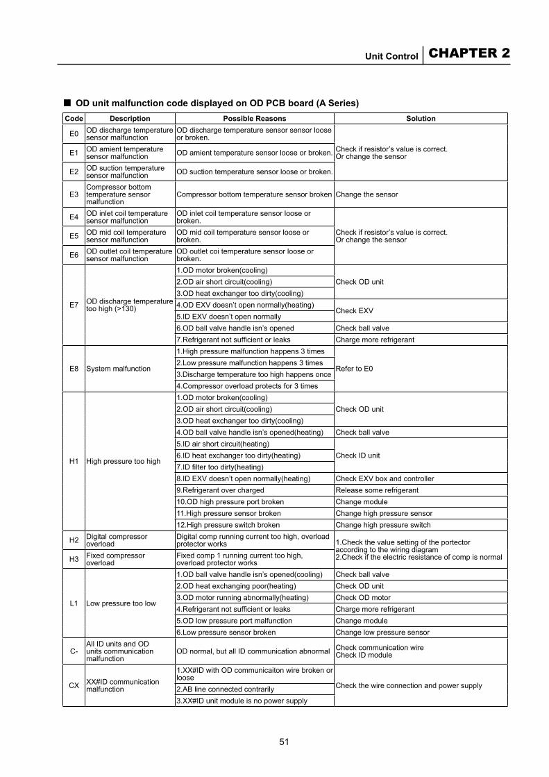
51
CHAPTER 2Unit Control
OD unit malfunction code displayed on OD PCB board (A Series)■Code Description Possible Reasons Solution
E0 OD discharge temperature sensor malfunction
OD discharge temperature sensor sensor loose or broken.
Check if resistor’s value is correct. Or change the sensorE1 OD amient temperature
sensor malfunction OD amient temperature sensor loose or broken.
E2 OD suction temperature sensor malfunction OD suction temperature sensor loose or broken.
E3Compressor bottom temperature sensor malfunction
Compressor bottom temperature sensor broken Change the sensor
E4 OD inlet coil temperature sensor malfunction
OD inlet coil temperature sensor loose or broken.
Check if resistor’s value is correct. Or change the sensorE5 OD mid coil temperature
sensor malfunctionOD mid coil temperature sensor loose or broken.
E6 OD outlet coil temperature sensor malfunction
OD outlet coi temperature sensor loose or broken.
E7 OD discharge temperature too high (>130)
1.OD motor broken(cooling)Check OD unit2.OD air short circuit(cooling)
3.OD heat exchanger too dirty(cooling)4.OD EXV doesn’t open normally(heating)
Check EXV5.ID EXV doesn’t open normally6.OD ball valve handle isn’s opened Check ball valve7.Refrigerant not sufficient or leaks Charge more refrigerant
E8 System malfunction
1.High pressure malfunction happens 3 times
Refer to E02.Low pressure malfunction happens 3 times3.Discharge temperature too high happens once4.Compressor overload protects for 3 times
H1 High pressure too high
1.OD motor broken(cooling)Check OD unit2.OD air short circuit(cooling)
3.OD heat exchanger too dirty(cooling)4.OD ball valve handle isn’s opened(heating) Check ball valve5.ID air short circuit(heating)
Check ID unit6.ID heat exchanger too dirty(heating)7.ID filter too dirty(heating)8.ID EXV doesn’t open normally(heating) Check EXV box and controller9.Refrigerant over charged Release some refrigerant10.OD high pressure port broken Change module11.High pressure sensor broken Change high pressure sensor12.High pressure switch broken Change high pressure switch
H2 Digital compressor overload
Digital comp running current too high, overload protector works 1.Check the value setting of the portector
according to the wiring diagram 2.Check if the electric resistance of comp is normalH3 Fixed compressor
overloadFixed comp 1 running current too high, overload protector works
L1 Low pressure too low
1.OD ball valve handle isn’s opened(cooling) Check ball valve2.OD heat exchanging poor(heating) Check OD unit3.OD motor running abnormally(heating) Check OD motor4.Refrigerant not sufficient or leaks Charge more refrigerant5.OD low pressure port malfunction Change module6.Low pressure sensor broken Change low pressure sensor
C-All ID units and OD units communication malfunction
OD normal, but all ID communication abnormal Check communication wire Check ID module
CX XX#ID communication malfunction
1.XX#ID with OD communicaiton wire broken or loose
Check the wire connection and power supply2.AB line connected contrarily3.XX#ID unit module is no power supply
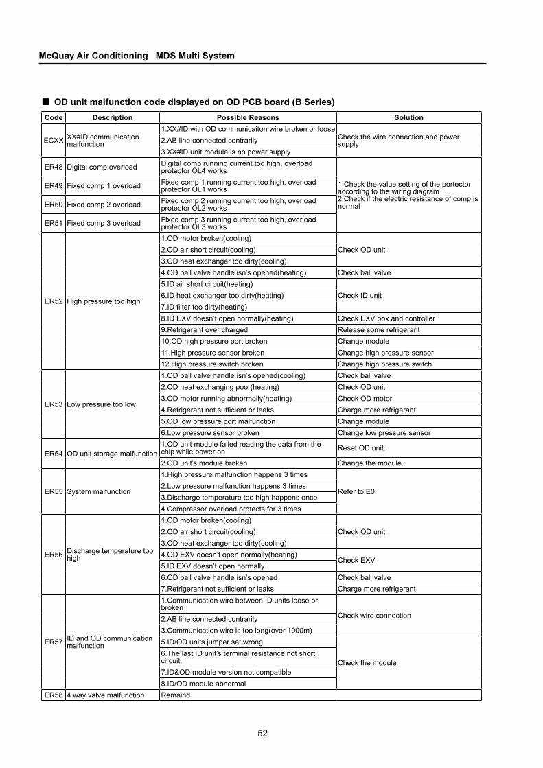
52
McQuay Air Conditioning MDS Multi System
OD unit malfunction code displayed on OD PCB board (B Series)■Code Description Possible Reasons Solution
ECXX XX#ID communication malfunction
1.XX#ID with OD communicaiton wire broken or looseCheck the wire connection and power supply2.AB line connected contrarily
3.XX#ID unit module is no power supply
ER48 Digital comp overload Digital comp running current too high, overload protector OL4 works
1.Check the value setting of the portector according to the wiring diagram 2.Check if the electric resistance of comp is normal
ER49 Fixed comp 1 overload Fixed comp 1 running current too high, overload protector OL1 works
ER50 Fixed comp 2 overload Fixed comp 2 running current too high, overload protector OL2 works
ER51 Fixed comp 3 overload Fixed comp 3 running current too high, overload protector OL3 works
ER52 High pressure too high
1.OD motor broken(cooling)Check OD unit2.OD air short circuit(cooling)
3.OD heat exchanger too dirty(cooling)4.OD ball valve handle isn’s opened(heating) Check ball valve5.ID air short circuit(heating)
Check ID unit6.ID heat exchanger too dirty(heating)7.ID filter too dirty(heating)8.ID EXV doesn’t open normally(heating) Check EXV box and controller9.Refrigerant over charged Release some refrigerant10.OD high pressure port broken Change module11.High pressure sensor broken Change high pressure sensor12.High pressure switch broken Change high pressure switch
ER53 Low pressure too low
1.OD ball valve handle isn’s opened(cooling) Check ball valve2.OD heat exchanging poor(heating) Check OD unit3.OD motor running abnormally(heating) Check OD motor4.Refrigerant not sufficient or leaks Charge more refrigerant5.OD low pressure port malfunction Change module6.Low pressure sensor broken Change low pressure sensor
ER54 OD unit storage malfunction1.OD unit module failed reading the data from the chip while power on Reset OD unit.
2.OD unit’s module broken Change the module.
ER55 System malfunction
1.High pressure malfunction happens 3 times
Refer to E02.Low pressure malfunction happens 3 times3.Discharge temperature too high happens once4.Compressor overload protects for 3 times
ER56 Discharge temperature too high
1.OD motor broken(cooling)Check OD unit2.OD air short circuit(cooling)
3.OD heat exchanger too dirty(cooling)4.OD EXV doesn’t open normally(heating)
Check EXV5.ID EXV doesn’t open normally6.OD ball valve handle isn’s opened Check ball valve7.Refrigerant not sufficient or leaks Charge more refrigerant
ER57 ID and OD communication malfunction
1.Communication wire between ID units loose or broken
Check wire connection2.AB line connected contrarily3.Communication wire is too long(over 1000m)5.ID/OD units jumper set wrong
Check the module6.The last ID unit’s terminal resistance not short circuit.7.ID&OD module version not compatible8.ID/OD module abnormal
ER58 4 way valve malfunction Remaind
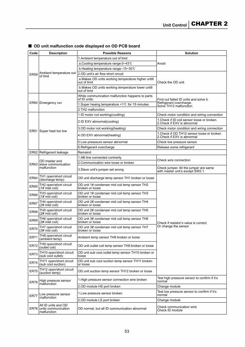
53
CHAPTER 2Unit Control
OD unit malfunction code displayed on OD PCB board■Code Description Possible Reasons Solution
ER59 Ambient temperature out of limit
1.Ambient temperature out of limitAvoid a.Cooling temperature range:0~43℃
b.Heating temperature range:-15~30℃2.OD unit’s air flow short circuit
Check the OD unit a.Makes OD units working temperature higher untill out of limit b.Makes OD units working temperature lower untill out of limit
ER60 Emergency run
While communication malfunction happens to parts of ID units: Find out failed ID untis and solve it.
Refrigerant overcharge. Solve TH12 malfunction.1.Super heaing temperature <1℃ for 15 minutes
2.TH2 malfunction
ER61 Super heat too low
1.ID motor not working(coolting) Check motor condition and wiring connection
2.ID EXV abnormal(cooling) 1.Check if ID coil sensor loose or broken 2.Check if EXV is abnormal
3.OD motor not working(heating) Check motor condition and wiring connection
4.OD EXV abnormal(heating) 1.Check if OD TH12 sensor loose or broken 2.Check if EXV is abnormal
5.Low presssure sensor abnormal Check low pressure sensor6.Refrigerant overcharge Release some refrigerant
ER62 Refrigerant leakage Remaind
ER63OD master and slave communication malfunction
1.AB line connected contrarilyCheck wire connection
2.Communication wire loose or broken
3.Slave unit’s jumper set wrong Check jumper. All the jumper are same with master unit’s except SW2.1.
ER64 TH1 open/short circuit (discharge temp) OD unit discharge temp sensor TH1 broken or loose
Check if resistor’s value is correct. Or change the sensor
ER65 TH2 open/short circuit (1# inlet coil)
OD unit 1# condenser mid coil temp sensor TH2 broken or loose
ER66 TH3 open/short circuit (1# mid coil)
OD unit 1# condenser mid coil temp sensor TH3 broken or loose
ER67 TH4 open/short circuit (2# inlet coil)
OD unit 2# condenser mid coil temp sensor TH4 broken or loose
ER68 TH5 open/short circuit (2# mid coil)
OD unit 2# condenser mid coil temp sensor TH5 broken or loose
ER69 TH6 open/short circuit (3# inlet coil)
OD unit 3# condenser mid coil temp sensor TH6 broken or loose
ER70 TH7 open/short circuit (3# mid coil)
OD unit 3# condenser mid coil temp sensor TH7 broken or loose
ER71 TH8 open/short circuit (ambient temp) Ambient temp sensor TH8 broken or loose
ER72 TH9 open/short circuit (outlet coil) OD unit outlet coil temp sensor TH9 broken or loose
ER73 TH10 open/short circuit (sub cool outlet)
OD unit sub cool outlet temp sensor TH10 broken or loose
ER74 TH11 open/short circuit (sub cool suction)
OD unit sub cool suction temp sensor TH11 broken or loose
ER75 TH12 open/short circuit (suction temp) OD unit suction temp sensor TH12 broken or loose
ER76 High pressure sensor malfunction
1.High pressure sensor connection wire broken Test high pressure sensor to confirm if it’s normal
2.OD module HS port broken Change module
ER77 Low pressure sensor malfunction
1.Low pressure sensor broken Test low pressure sensor to confirm if it’s normal
2.OD module LS port broken Change module
ER78All ID units and OD units communication malfunction
OD normal, but all ID communication abnormal Check communication wire Check ID module
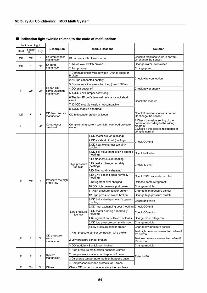
54
McQuay Air Conditioning MDS Multi System
Indication light twinkle related to the code of malfunction:■Indication Light
Description Possible Reasons SolutionHeat Sleep/
Fan Dry
Off Off F ID temp sensor malfunction ID unit sensor broken or loose Check if resistor’s value is correct.
Or change the sensor.
Off F Off ID pump malfunction
1.Water level switch broken Change water level switch2.Pump broken Change pump
F Off OffID and OD communication malfunction
1.Communication wire between ID units loose or broken
Check wire connection2.AB line connected contrily3.Communication wire is too long (over 1000m)4.OD unit power off Check power supply5.ID/OD units jumper set wrong
Check the module6.The last ID unit’s terminal resistance not short circuit.7.ID&OD module version not compatible8.ID/OD module abnormal
Off F F OD temp sensor malfunction OD unit sensor broken or loose Check if resistor’s value is correct.
Or change the sensor.
F F Off Compressor overload
Comp running current too high, overload protector works
1.Check the value setting of the portector according to the wiring diagram 2.Check if the electric resistance of comp is normal
F Off F Pressure too high or too low
High pressure too high
1.OD motor broken (cooling)
Check OD unit2.OD air short circuit (cooling)3.OD heat exchanger too dirty (cooling)4.OD ball valve handle isn’s opened (heating) Check ball valve
5.ID air short circuit (heating)
Check ID unit6.ID heat exchanger too dirty (heating)7.ID filter too dirty (heating)8.ID EXV doesn’t open normally (heating) Check EXV box and controller
9.Refrigerant over charged Release some refrigerant10.OD high pressure port broken Change module11.High pressure sensor broken Change high pressure sensor12.High pressure switch broken Change high pressure switch
Low pressure too low
1.OD ball valve handle isn’s opened (cooling) Check ball valve
2.OD heat exchanging poor (heating) Check OD unit3.OD motor running abnormally (heating) Check OD motor
4.Refrigerant not sufficient or leaks Charge more refrigerant5.OD low pressure port malfunction Change module6.Low pressure sensor broken Change low pressure sensor
F F OnOD pressure sensor malfunction
1.High pressure sensor connection wire broken Test high pressure sensor to confirm if it’s normal
2.Low pressure sensor broken Test low pressure sensor to confirm if it’s normal
3.OD module HS or LS port broken Change module
F F F System malfunction
1.High pressure malfunction happens 3 times
Refer to E02.Low pressure malfunction happens 3 times3.Discharge temperature too high happens once4.Compressor overload protects for 3 times
F On On Others Check OD unit error code to solve the problems

55
CHAPTER 2Unit Control
2.7 Features of MC501MC501 can be used as a burner to burn control program for MDS indoor and outdoor units.MC501 can be used as a communication transformer to facilitate RS232 & RS485, USB & RS485 and RS485 & RS485 communication.
2.7.1 Application
Used as a burnerConfigure the jumper as instructed by the figure. Connect MC501 to a PC serial port. Plug in a 9V power supply. Then you can start burning.
■
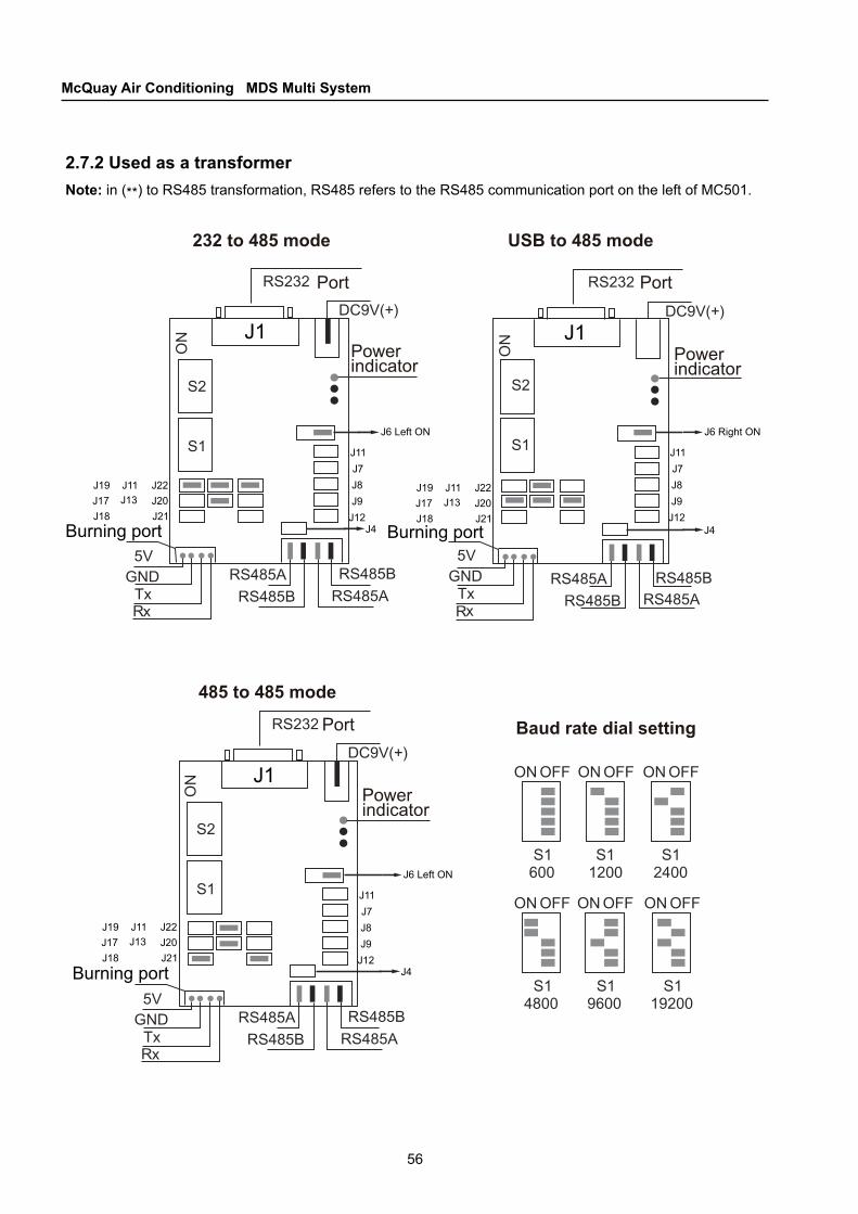
56
McQuay Air Conditioning MDS Multi System
J1
J1 J1
J6 Left ON
J11J7J8J9
J12
J11J7J8J9
J12
J11J7J8J9
J12
Port
Power indicator
Port
232 to 485 mode
485 to 485 mode
Baud rate dial setting
Power indicator
Port
Power indicator
USB to 485 mode
Burning port Burning port
Burning port
J19J17J18
J11J13
J22J20J21
J19J17J18
J11J13
J22J20J21
J19J17J18
J11J13
J22J20J21
J6 Left ON J6 Right ON
J4
J4 J4
2.7.2 Used as a transformerNote: in (**) to RS485 transformation, RS485 refers to the RS485 communication port on the left of MC501.
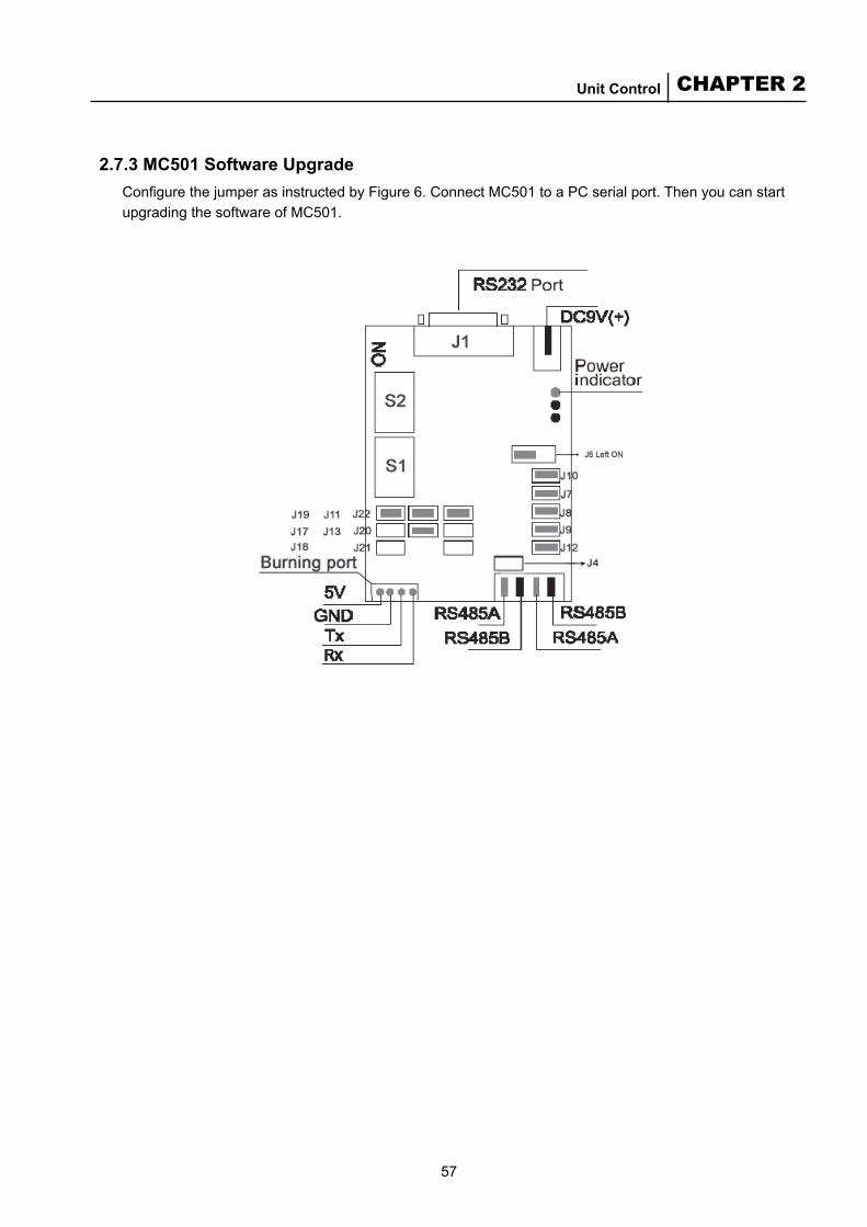
57
CHAPTER 2Unit Control
2.7.3 MC501 Software UpgradeConfigure the jumper as instructed by Figure 6. Connect MC501 to a PC serial port. Then you can start upgrading the software of MC501.
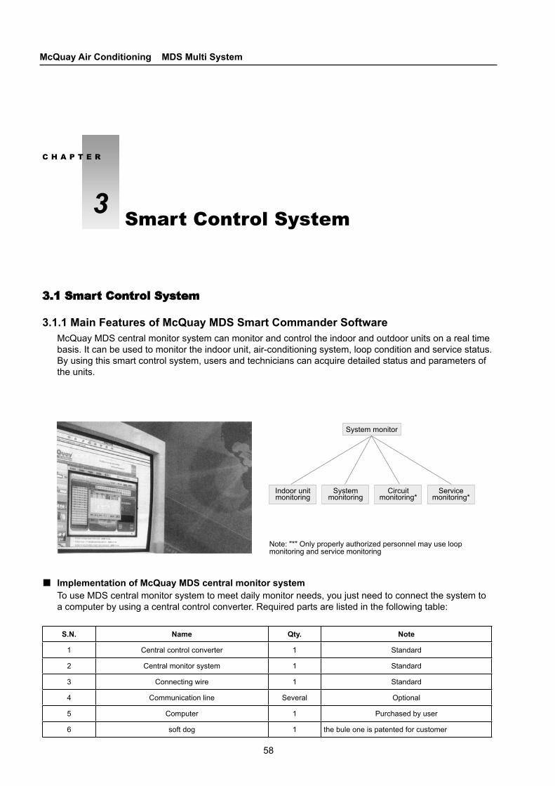
58
McQuay Air Conditioning MDS Multi System
Indoor unit monitoring
System monitoring
Circuit monitoring*
Service monitoring*
Note: "*" Only properly authorized personnel may use loop monitoring and service monitoring
System monitor
3.1 Smart Control System
3.1.1 Main Features of McQuay MDS Smart Commander SoftwareMcQuay MDS central monitor system can monitor and control the indoor and outdoor units on a real time basis. It can be used to monitor the indoor unit, air-conditioning system, loop condition and service status. By using this smart control system, users and technicians can acquire detailed status and parameters of the units.
Implementation of McQuay MDS central monitor systemTo use MDS central monitor system to meet daily monitor needs, you just need to connect the system to a computer by using a central control converter. Required parts are listed in the following table:
■
S.N. Name Qty. Note
1 Central control converter 1 Standard
2 Central monitor system 1 Standard
3 Connecting wire 1 Standard
4 Communication line Several Optional
5 Computer 1 Purchased by user
6 soft dog 1 the bule one is patented for customer
C H A P T E R
3 Smart Control System
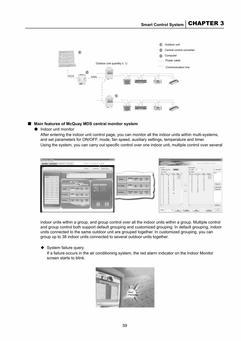
59
CHAPTER 3Smart Control System
Outdoor unit quantity ≤
Outdoor unit
Central control converter
Computer
Power cable
Communication line
Main features of McQuay MDS central monitor system● Indoor unit monitor
After entering the indoor unit control page, you can monitor all the indoor units within multi-systems, and set parameters for ON/OFF, mode, fan speed, auxiliary settings, temperature and timer.Using the system, you can carry out specific control over one indoor unit, multiple control over several
■
indoor units within a group, and group control over all the indoor units within a group. Multiple control and group control both support default grouping and customized grouping. In default grouping, indoor units connected to the same outdoor unit are grouped together. In customized grouping, you can group up to 38 indoor units connected to several outdoor units together.
◆System failure queryIf a failure occurs in the air conditioning system, the red alarm indicator on the Indoor Monitor screen starts to blink.
Alert message
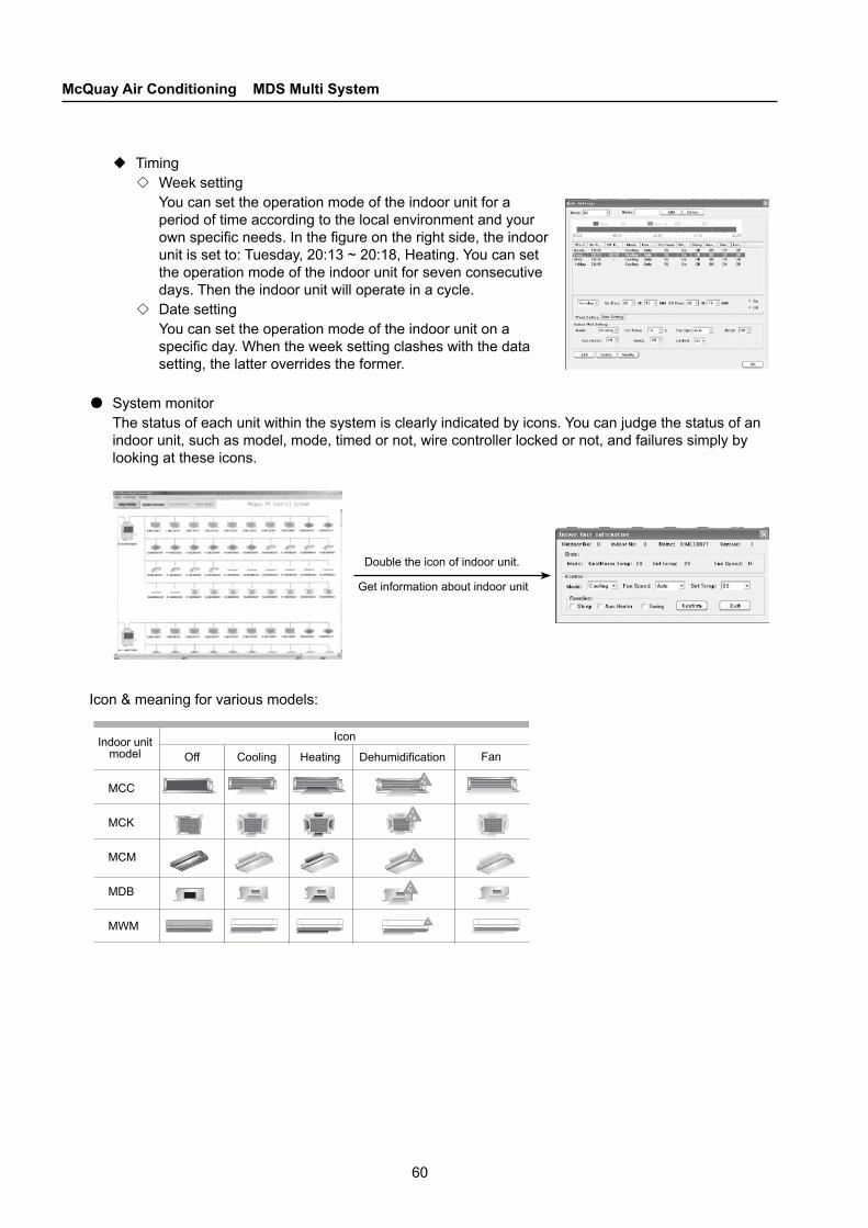
60
McQuay Air Conditioning MDS Multi System
MCC
MCK
MCM
MDB
MWM
Indoor unit model Off Cooling Heating Dehumidification
Icon
Double the icon of indoor unit.
Get information about indoor unit
◆Timing◇Week setting
You can set the operation mode of the indoor unit for a period of time according to the local environment and your own specific needs. In the figure on the right side, the indoor unit is set to: Tuesday, 20:13 ~ 20:18, Heating. You can set the operation mode of the indoor unit for seven consecutive days. Then the indoor unit will operate in a cycle.
◇Date settingYou can set the operation mode of the indoor unit on a specific day. When the week setting clashes with the data setting, the latter overrides the former.
●System monitorThe status of each unit within the system is clearly indicated by icons. You can judge the status of an indoor unit, such as model, mode, timed or not, wire controller locked or not, and failures simply by looking at these icons.
Icon & meaning for various models:
Fan
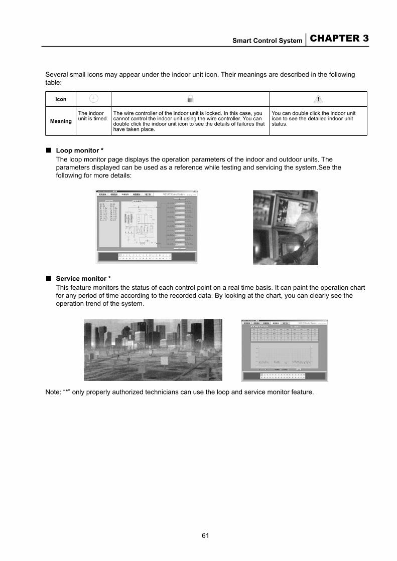
61
CHAPTER 3Smart Control System
Several small icons may appear under the indoor unit icon. Their meanings are described in the following table:
Icon
MeaningThe indoor unit is timed.
The wire controller of the indoor unit is locked. In this case, you cannot control the indoor unit using the wire controller. You can double click the indoor unit icon to see the details of failures that have taken place.
You can double click the indoor unit icon to see the detailed indoor unit status.
Loop monitor *The loop monitor page displays the operation parameters of the indoor and outdoor units. The parameters displayed can be used as a reference while testing and servicing the system.See the following for more details:
■
Service monitor *This feature monitors the status of each control point on a real time basis. It can paint the operation chart for any period of time according to the recorded data. By looking at the chart, you can clearly see the operation trend of the system.
■
Note: “*” only properly authorized technicians can use the loop and service monitor feature.
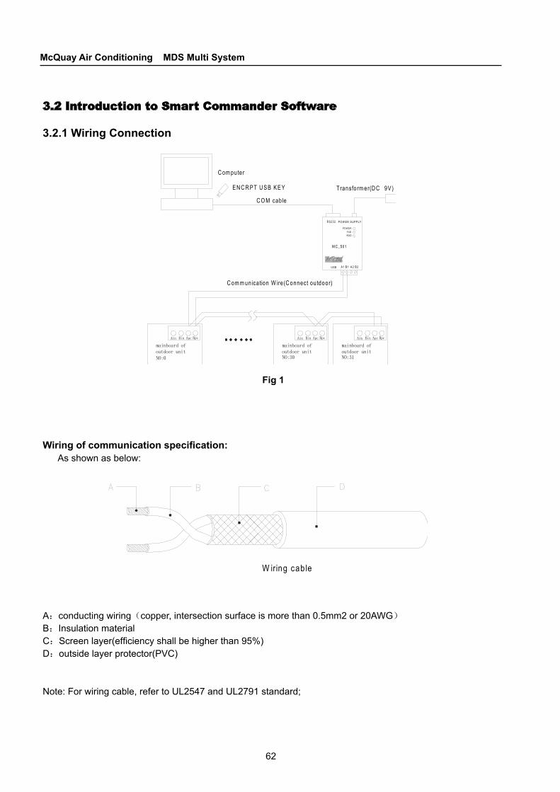
62
McQuay Air Conditioning MDS Multi System
T ransfo rm er(D C 9V )
C om puter
C om m unica tion W ire (C onnect ou tdoor)
C O M cab le
A 2B 1A 1 B 2
M C _501
R S 232
U S B
P O W E R S U P P LY
P O W E RFX DR X D
E N C R P T U S B K E Y
3.2 Introduction to Smart Commander Software
3.2.1 Wiring Connection
Fig 1
Wiring of communication specification:As shown as below:
W iring cab le
A:conducting wiring(copper, intersection surface is more than 0.5mm2 or 20AWG)
B:Insulation material C:Screen layer(efficiency shall be higher than 95%)D:outside layer protector(PVC)
Note: For wiring cable, refer to UL2547 and UL2791 standard;
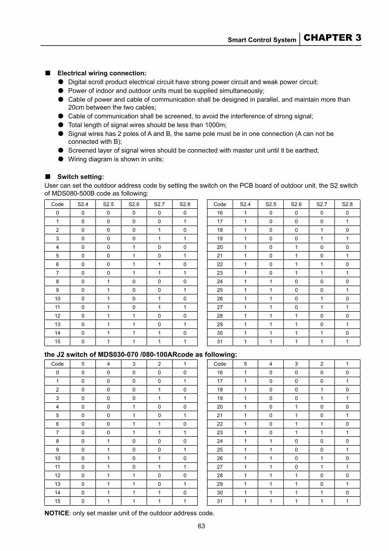
63
CHAPTER 3Smart Control System
■ Electrical wiring connection:●Digital scroll product electrical circuit have strong power circuit and weak power circuit;●Power of indoor and outdoor units must be supplied simultaneously;●Cable of power and cable of communication shall be designed in parallel, and maintain more than 20cm between the two cables;●Cable of communication shall be screened, to avoid the interference of strong signal;●Total length of signal wires should be less than 1000m;●Signal wires has 2 poles of A and B, the same pole must be in one connection (A can not be connected with B);●Screened layer of signal wires should be connected with master unit until it be earthed;●Wiring diagram is shown in units;
■ Switch setting:User can set the outdoor address code by setting the switch on the PCB board of outdoor unit. the S2 switch of MDS080-500B code as following:
the J2 switch of MDS030-070 /080-100ARcode as following:
Code S2.4 S2.5 S2.6 S2.7 S2.80 0 0 0 0 01 0 0 0 0 12 0 0 0 1 03 0 0 0 1 14 0 0 1 0 05 0 0 1 0 16 0 0 1 1 07 0 0 1 1 18 0 1 0 0 09 0 1 0 0 1
10 0 1 0 1 011 0 1 0 1 112 0 1 1 0 013 0 1 1 0 114 0 1 1 1 015 0 1 1 1 1
Code S2.4 S2.5 S2.6 S2.7 S2.816 1 0 0 0 017 1 0 0 0 118 1 0 0 1 019 1 0 0 1 120 1 0 1 0 021 1 0 1 0 122 1 0 1 1 023 1 0 1 1 124 1 1 0 0 025 1 1 0 0 126 1 1 0 1 027 1 1 0 1 128 1 1 1 0 029 1 1 1 0 130 1 1 1 1 031 1 1 1 1 1
Code 5 4 3 2 10 0 0 0 0 01 0 0 0 0 12 0 0 0 1 03 0 0 0 1 14 0 0 1 0 05 0 0 1 0 16 0 0 1 1 07 0 0 1 1 18 0 1 0 0 09 0 1 0 0 1
10 0 1 0 1 011 0 1 0 1 112 0 1 1 0 013 0 1 1 0 114 0 1 1 1 015 0 1 1 1 1
Code 5 4 3 2 116 1 0 0 0 017 1 0 0 0 118 1 0 0 1 019 1 0 0 1 120 1 0 1 0 021 1 0 1 0 122 1 0 1 1 023 1 0 1 1 124 1 1 0 0 025 1 1 0 0 126 1 1 0 1 027 1 1 0 1 128 1 1 1 0 029 1 1 1 0 130 1 1 1 1 031 1 1 1 1 1
NOTICE: only set master unit of the outdoor address code.
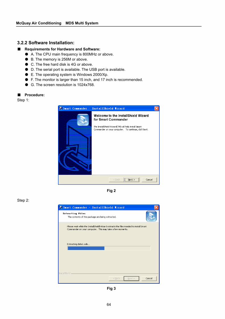
64
McQuay Air Conditioning MDS Multi System
Fig 3
3.2.2 Software Installation:■ Requirements for Hardware and Software:
●A. The CPU main frequency is 800MHz or above. ●B. The memory is 256M or above. ●C. The free hard disk is 4G or above. ●D. The serial port is available. The USB port is available.●E. The operating system is Windows 2000/Xp. ●F. The monitor is larger than 15 inch, and 17 inch is recommended.●G. The screen resolution is 1024x768.
■ Procedure:Step 1:
Fig 2
Step 2:
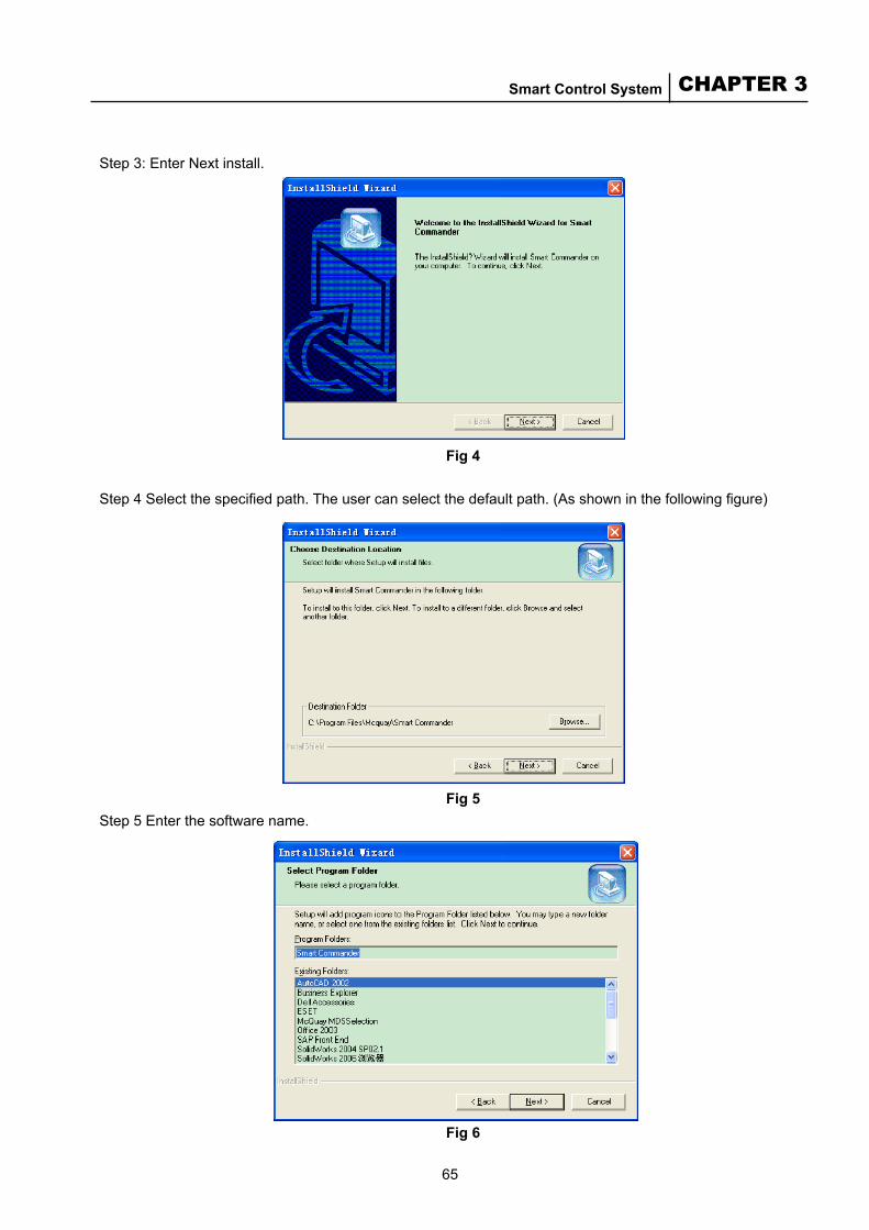
65
CHAPTER 3Smart Control System
Fig 5
Fig 4
Step 3: Enter Next install.
Step 4 Select the specified path. The user can select the default path. (As shown in the following figure)
Step 5 Enter the software name.
Fig 6

66
McQuay Air Conditioning MDS Multi System
3.2.3 User Login:
Fig 7
NOTE: User must install the driver of ENCRYPT USB KEY in front of login the software. The driver file is SPI730RC9 (in installation CD). You can login after put the ENCRYPT USB KEY into the computer, and keep the right user name and the code only. So please keep your code key properly
3.2.4 Basic Concepts:■ Single Control, Multiple Control and Group Control◆Limits:
●The indoor unit cannot be set to the heating mode when the outdoor unit is in cooling or dehumidity mode. Otherwise, mode conflict appears.
●The indoor unit cannot be set to cooling or dehumidity mode when the outdoor unit is in heating mode. Otherwise, mode conflict appears. ●If the indoor unit is to be set to the heating mode when the outdoor unit is in cooling or dehumidity
mode, turn off all indoor units connected with this outdoor unit, or set the indoor unit to air vent mode. Then turn on indoor units and set them to the heating mode. It is the same to set the indoor unit to cooling or dehumidity mode when the outdoor unit is in heating mode.
●The setting temperature must be set between 16 to 30°C. ● The wing wind function of the indoor unit is only applicable for MCM, MCK and MWM series. ● The user cannot select the cooling mode and the auxiliary heating mode simultaneously. ● The user cannot select the dehumidity mode and the auxiliary heating mode simultaneously. ● H. The indoor unit cannot be set to the sleep mode when it is not in the cooling or heating mode.

67
CHAPTER 3Smart Control System
Fig 8
Single control means that the user can control one indoor unit in a group using the monitor software. As shown in the following figure
Multiple control means that the user can control multiple indoor units in a group using the monitor software. As shown in the following figure
Fig 9

68
McQuay Air Conditioning MDS Multi System
Group control means that the user can control all indoor units in a group using the monitor software. As shown in the following figure
Fig 10
■ Timing, Mode and TaskTiming means that the monitor software sets time to each indoor unit of MDS system, such as time to turn on/off the indoor unit, or changing the indoor unit status at some time etc.Mode is set to ease the timing setting. Multiple tasks can be set in a mode. A mode can contain multiple tasks.Task means the specified command the indoor unit executing in a specified time setting in the timing mode.Relationship between task and timing is as follows:
Fig 11

69
CHAPTER 3Smart Control System
■ System Monitor and Indoor MonitorSystem monitor: From the second tab on the left, you canquery the model and status of the indoor and outdoor units, and can perform single control to each unit.As shown in the following figure
Indoor control: From the first tab on the left, you can perform related operation to the indoor units connected to the outdoor unit.As shown in the following figure
Fig 13
Fig 12

70
McQuay Air Conditioning MDS Multi System
■ Customized Group and Name:Customized group: To ease the control of indoor units connected to different outdoor units in the multi-online system, group these indoor units using customized group method so that the user can operate the units easily. Customized name: In the MDS system, each indoor unit has a default name, namely, outdoor unit number-indoor unit number. For example, 0-1, which means indoor unit NO.1 connected outdoor unit NO.0. But it is easier to remember the location of each indoor unit in actual use for the user, such as meeting rooms and libraries (less than 16 characters). So the customized name is generated. (Only the interior service personnel of Shenzhen McQuay air condictioning Co ., Ltd. can use the circuit monitor and the service monitor)
Fig 14
3.2.5 Function Operation: ■ Menu Introduction:
Fig 15
71
CHAPTER 3Smart Control System
●Initiating: If the operating environment of the hardware changes (for example: the quantity of indoor or outdoor changes, the type of the indoor changes), customs can click this function, the software will monitor the dates of indoor and outdoor.
●Error History: To record the date and the time of the indoor and outdoor’s faults in the system.●User Management: To manage the name and the pass-words of the users.●Parameter Setting: To set the parameter of the system, It is better to perform by the service persons.● Manager Owner: To manage the owner .● Static Indoor status: To stat the indoors running time data.● State History: To stat the units running data.
■ Control of One or More Indoor Units: The user can select the default group or customized group to perform single control or multiple control. (Note: the function of “locked” can be performed single control、 multiple control or group control)●To perform single control, follow these steps.:
A. Select the outdoor unit number button. B. Select the indoor unit number button. C. Select Mode, Speed or Auxiliary buttons to set functions as needed. D. Adjust the indoor temperature as needed. E. Click the Apply button to perform the operation.
●To perform Multiple control, follow these steps: A. Select the outdoor unit number button. B. Select the indoor unit number button. In multiple control mode, the user can click buttons to select multiple indoor units. C. Select Mode, Speed or Auxiliary buttons to set functions as needed. D. Adjust the indoor temperature as needed. E. Click the Confirm button to perform.
●To perform Group control, follow these steps: A. Select the outdoor unit number button. B. Select the indoor unit number button. In Group control mode, the user can click buttons to select multiple indoor units. C. Select Mode, Speed or Auxiliary buttons to set functions as needed. D. Adjust the indoor temperature as needed. E. Click the Apply button to perform.
●To perform Group control, follow these steps: A. Select the outdoor unit number button. B. Select the indoor unit number button. In Group control mode, the user can click buttons to select multiple indoor units. C. Select Mode, Speed or Auxiliary buttons to set functions as needed. D. Adjust the indoor temperature as needed. E. Click the Apply button to perform.

72
McQuay Air Conditioning MDS Multi System
■ Customized Group Setting: A. Click the Group and Timing buttons. B. Select Default group indoor unit number -> Outdoor unit number (As shown in the Fig 16).
As shown in the following figure
Select the indoor unit number. (Press Shift to select multiple indoor units numbers.) (As shown in the Fig 17)Note: The max. members in a customized group is 48. As shown in the following figure
Fig 16
Fig 17
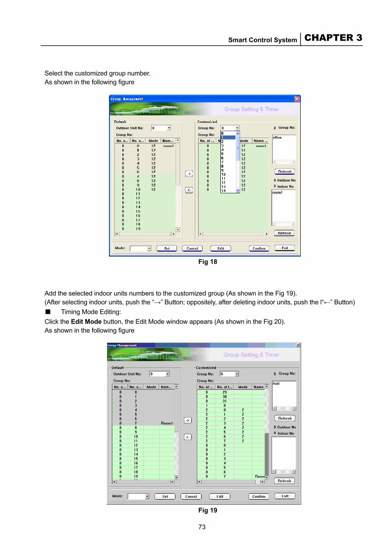
73
CHAPTER 3Smart Control System
Select the customized group number.As shown in the following figure
Fig 18
Add the selected indoor units numbers to the customized group (As shown in the Fig 19).(After selecting indoor units, push the “→” Button; oppositely, after deleting indoor units, push the l“←” Button)■ Timing Mode Editing:Click the Edit Mode button, the Edit Mode window appears (As shown in the Fig 20).As shown in the following figure
Fig 19
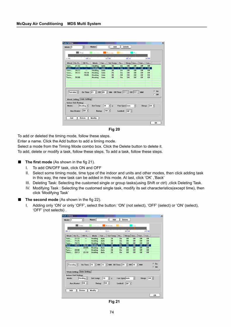
74
McQuay Air Conditioning MDS Multi System
Fig 20To add or deleted the timing mode, follow these steps.Enter a name. Click the Add button to add a timing mode.Select a mode from the Timing Mode combo box. Click the Delete button to delete it.To add, delete or modify a task, follow these steps. To add a task, follow these steps.
■ The first mode (As shown in the fig 21).I. To add ON/OFF task, click ON and OFFII. Select some timing mode, time type of the indoor and units and other modes, then click adding task
in this way, the new task can be added in this mode. At last, click ’OK’ ,’Back’ III. Deleting Task: Selecting the customed single or group tasks(using Shift or ctrl) ,click Deleting Task.IV. Modifying Task : Selecting the customed single task, modify its set characteristics(except time), then
click ‘Modifying Task’
■ The second mode (As shown in the fig 22).I. Adding only ‘ON’ or only ‘OFF’, select the button: ‘ON’ (not select), ‘OFF’ (select) or ‘ON’ (select),
‘OFF’ (not selects) .
Fig 21
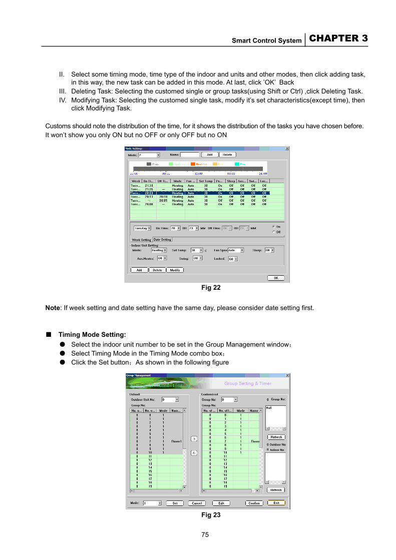
75
CHAPTER 3Smart Control System
II. Select some timing mode, time type of the indoor and units and other modes, then click adding task, in this way, the new task can be added in this mode. At last, click ’OK’ Back
III. Deleting Task: Selecting the customed single or group tasks(using Shift or Ctrl) ,click Deleting Task. IV. Modifying Task: Selecting the customed single task, modify it’s set characteristics(except time), then
click Modifying Task.
Customs should note the distribution of the time, for it shows the distribution of the tasks you have chosen before. It won’t show you only ON but no OFF or only OFF but no ON
Fig 22
Note: If week setting and date setting have the same day, please consider date setting first.
■ Timing Mode Setting:● Select the indoor unit number to be set in the Group Management window;
● Select Timing Mode in the Timing Mode combo box;● Click the Set button;As shown in the following figure
Fig 23
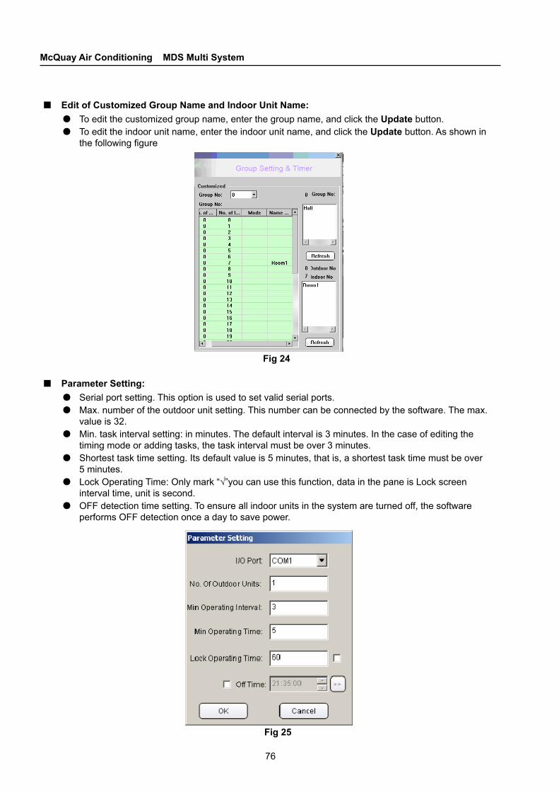
76
McQuay Air Conditioning MDS Multi System
■ Edit of Customized Group Name and Indoor Unit Name:● To edit the customized group name, enter the group name, and click the Update button.● To edit the indoor unit name, enter the indoor unit name, and click the Update button. As shown in
the following figure
Fig 24
■ Parameter Setting:● Serial port setting. This option is used to set valid serial ports.● Max. number of the outdoor unit setting. This number can be connected by the software. The max.
value is 32.● Min. task interval setting: in minutes. The default interval is 3 minutes. In the case of editing the
timing mode or adding tasks, the task interval must be over 3 minutes.● Shortest task time setting. Its default value is 5 minutes, that is, a shortest task time must be over
5 minutes.● Lock Operating Time: Only mark “√”you can use this function, data in the pane is Lock screen
interval time, unit is second.● OFF detection time setting. To ensure all indoor units in the system are turned off, the software
performs OFF detection once a day to save power.
Fig 25

77
CHAPTER 3Smart Control System
● Some indoor units can be set without the OFF detection. Click the Double-arrow button to edit all indoor units numbers.
Fig 26
■ User Management:● The name is “admin” and the password first loading is “mcquaymds”. This name can’t be modified ,
the password can be modified. Please keeping the password validly!● To add a user, enter the user name and password, and click the Add User button.● To modify a user, enter the user name, and click the Modify User button. Note that only the
password can be modified.● To delete a user, select the user to be deleted in the user listing, and click the Delete User button.
As shown in the following figure
Fig 27

78
McQuay Air Conditioning MDS Multi System
■ Prompts for Fault Records and Real-time Fault● The fault records list the faults took place in the whole system.
Fig 28
● Real-time fault. In case that any faults occur in the system, a red indicator blink on the upper right in the Indoor Monitor page. Double-click the red indicator. The Real-time Fault window pops up.
(Red light)
Fig 29
Fig 30
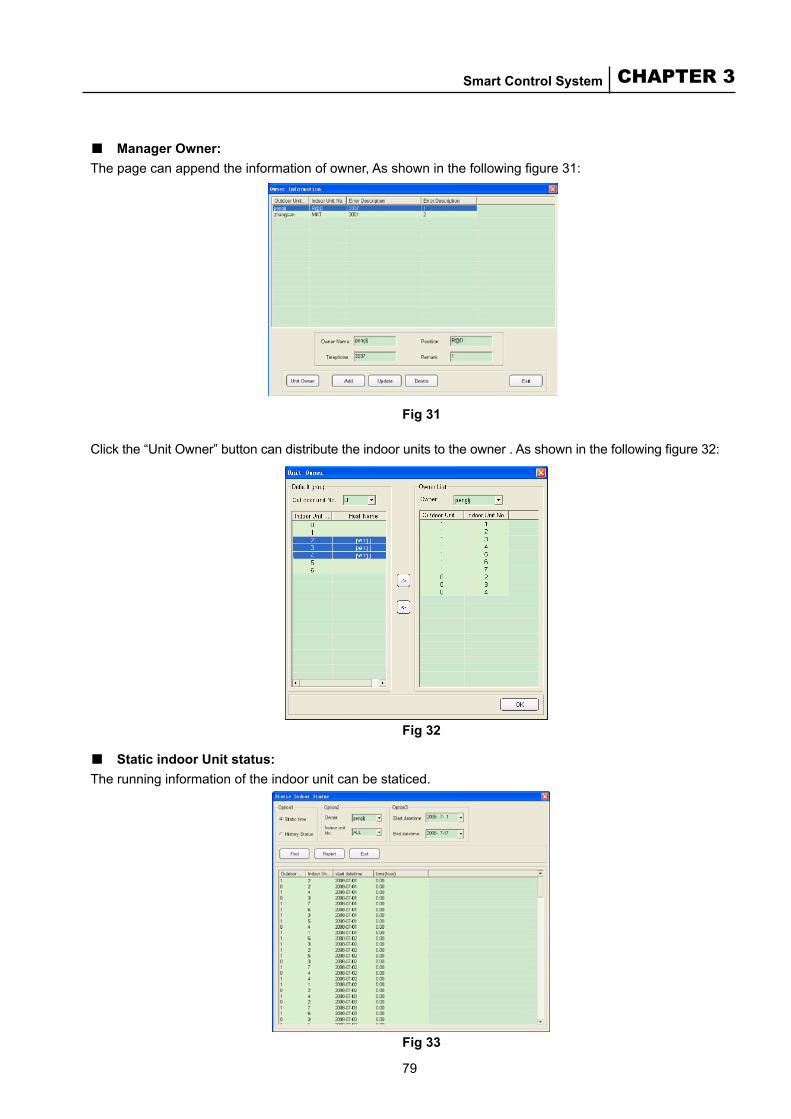
79
CHAPTER 3Smart Control System
■ Manager Owner:The page can append the information of owner, As shown in the following figure 31:
Fig 31
Click the “Unit Owner” button can distribute the indoor units to the owner . As shown in the following figure 32:
Fig 32
■ Static indoor Unit status:The running information of the indoor unit can be staticed.
Fig 33
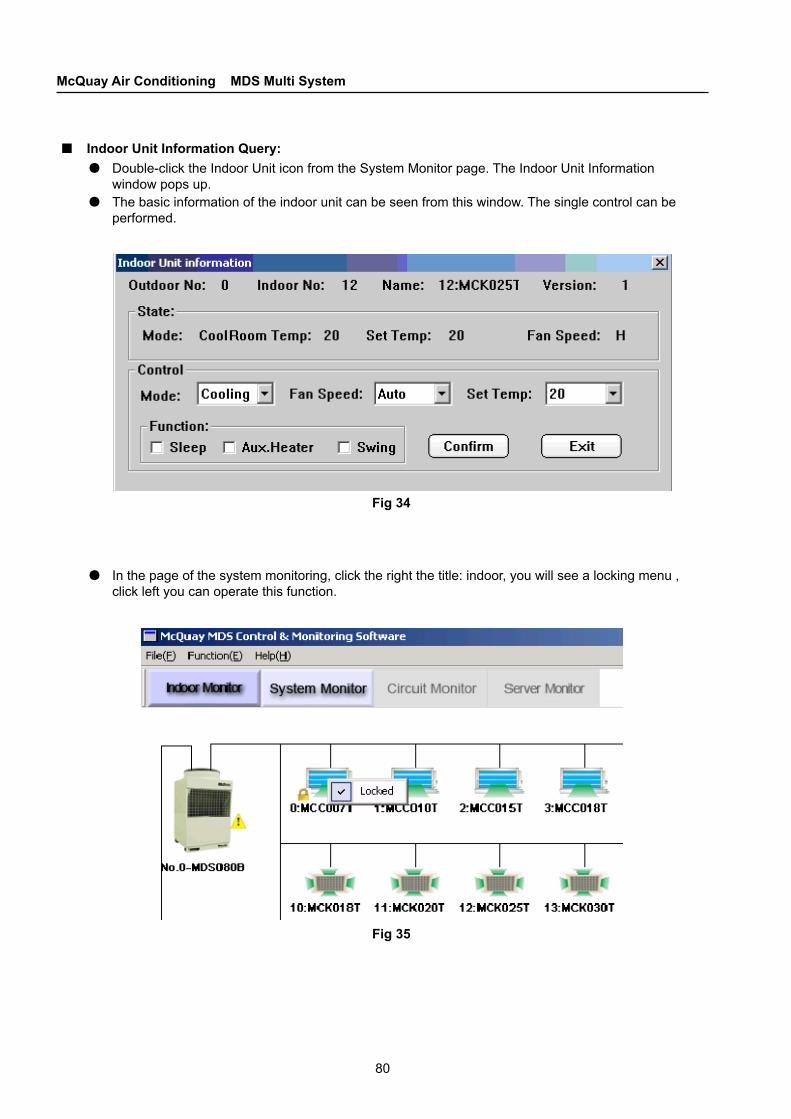
80
McQuay Air Conditioning MDS Multi System
■ Indoor Unit Information Query:● Double-click the Indoor Unit icon from the System Monitor page. The Indoor Unit Information
window pops up.● The basic information of the indoor unit can be seen from this window. The single control can be
performed.
Fig 34
● In the page of the system monitoring, click the right the title: indoor, you will see a locking menu , click left you can operate this function.
Fig 35

81
CHAPTER 3Smart Control System
3.2.6 Icon Description:■ Model Icon:
modelIcon
Stop Cooling Heating Dehumidity Air vent
MCC(green) (red)
MCK
MCM
MDB
MWM
Fig 36
■ Status Icon:
Mode
Cooling Heating Dehumidity Air vent
Speed
Automatic High Middle Low
Auxili-ary
Locked Sleep Auxiliary heating Swing wind
The applied button
Down set temp. Up set temp. OFF ON
Fig 37
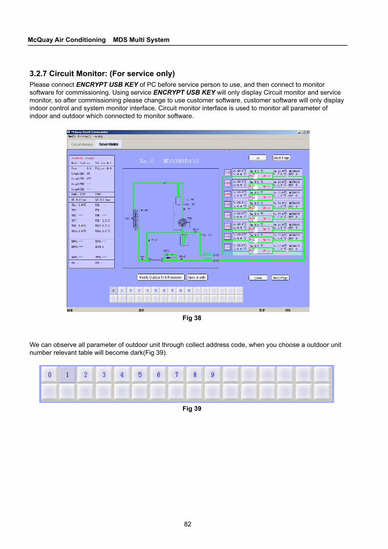
82
McQuay Air Conditioning MDS Multi System
3.2.7 Circuit Monitor: (For service only)Please connect ENCRYPT USB KEY of PC before service person to use, and then connect to monitor software for commissioning. Using service ENCRYPT USB KEY will only display Circuit monitor and service monitor, so after commissioning please change to use customer software, customer software will only display indoor control and system monitor interface. Circuit monitor interface is used to monitor all parameter of indoor and outdoor which connected to monitor software.
Fig 38
We can observe all parameter of outdoor unit through collect address code, when you choose a outdoor unit number relevant table will become dark(Fig 39).
Fig 39
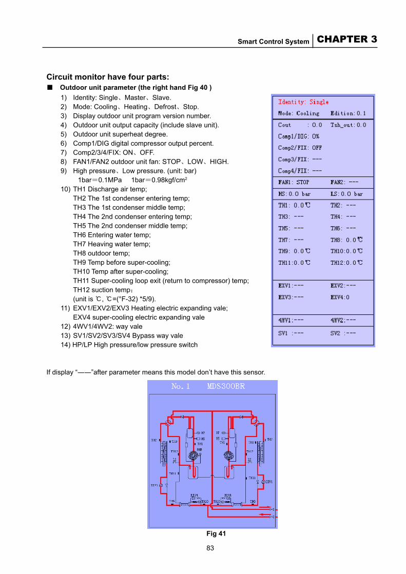
83
CHAPTER 3Smart Control System
Circuit monitor have four parts:■ Outdoor unit parameter (the right hand Fig 40 )
1) Identity: Single、Master、Slave.2) Mode: Cooling、Heating、Defrost、Stop.3) Display outdoor unit program version number.4) Outdoor unit output capacity (include slave unit).5) Outdoor unit superheat degree.6) Comp1/DIG digital compressor output percent.7) Comp2/3/4/FIX: ON、OFF.8) FAN1/FAN2 outdoor unit fan: STOP、LOW、HIGH.9) High pressure、Low pressure. (unit: bar) 1bar=0.1MPa 1bar=0.98kgf/cm2
10) TH1 Discharge air temp; TH2 The 1st condenser entering temp; TH3 The 1st condenser middle temp; TH4 The 2nd condenser entering temp; TH5 The 2nd condenser middle temp; TH6 Entering water temp; TH7 Heaving water temp; TH8 outdoor temp; TH9 Temp before super-cooling; TH10 Temp after super-cooling; TH11 Super-cooling loop exit (return to compressor) temp; TH12 suction temp; (unit is ℃, ℃=(°F-32) *5/9).11) EXV1/EXV2/EXV3 Heating electric expanding vale; EXV4 super-cooling electric expanding vale12) 4WV1/4WV2: way vale13) SV1/SV2/SV3/SV4 Bypass way vale14) HP/LP High pressure/low pressure switch
If display “――”after parameter means this model don’t have this sensor.
Fig 41
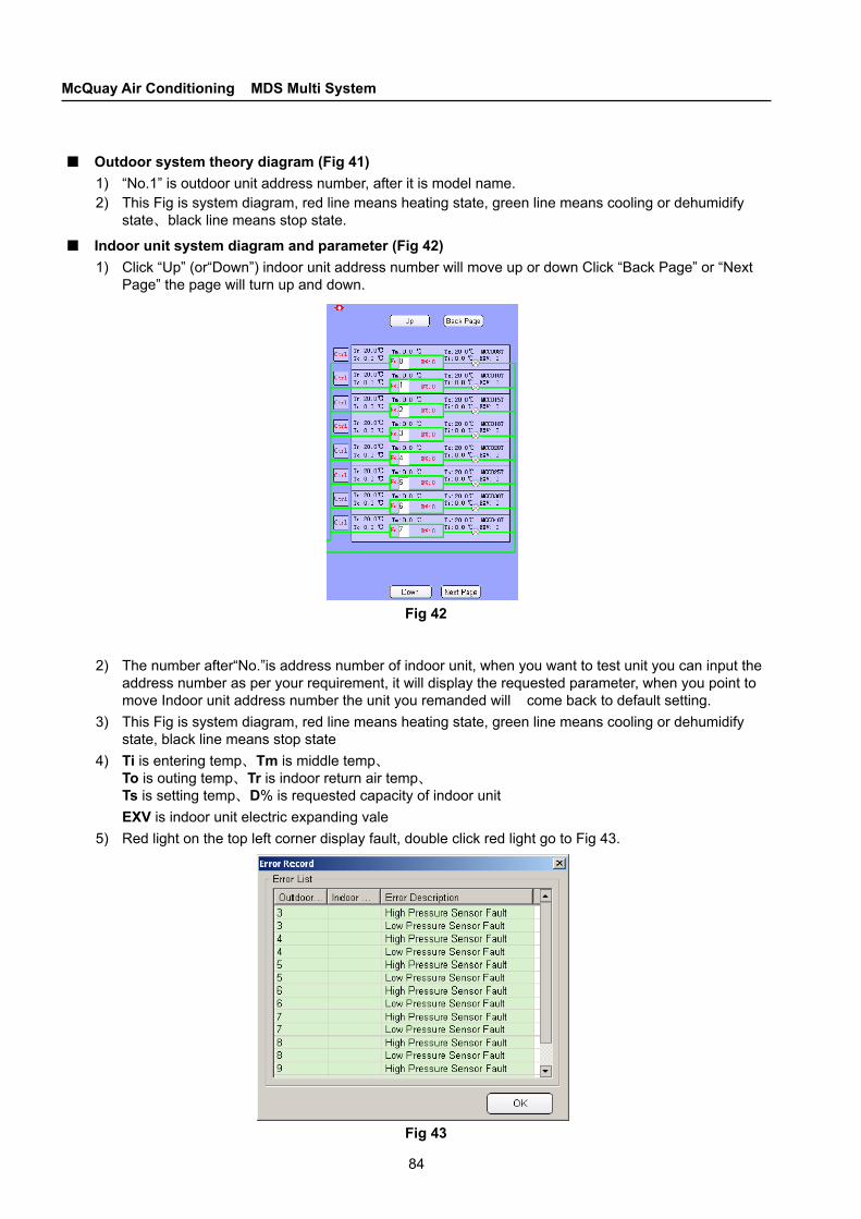
84
McQuay Air Conditioning MDS Multi System
■ Outdoor system theory diagram (Fig 41)1) “No.1” is outdoor unit address number, after it is model name.2) This Fig is system diagram, red line means heating state, green line means cooling or dehumidify
state、black line means stop state.
■ Indoor unit system diagram and parameter (Fig 42)1) Click “Up” (or“Down”) indoor unit address number will move up or down Click “Back Page” or “Next
Page” the page will turn up and down.
Fig 42
2) The number after“No.”is address number of indoor unit, when you want to test unit you can input the address number as per your requirement, it will display the requested parameter, when you point to move Indoor unit address number the unit you remanded will come back to default setting.
3) This Fig is system diagram, red line means heating state, green line means cooling or dehumidify state, black line means stop state
4) Ti is entering temp、Tm is middle temp、 To is outing temp、Tr is indoor return air temp、 Ts is setting temp、D% is requested capacity of indoor unit
EXV is indoor unit electric expanding vale5) Red light on the top left corner display fault, double click red light go to Fig 43.
Fig 43
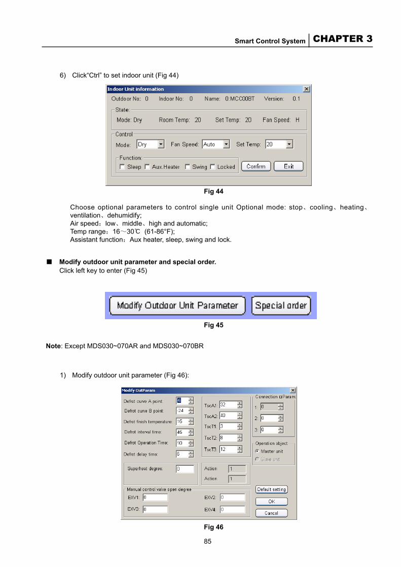
85
CHAPTER 3Smart Control System
6) Click“Ctrl” to set indoor unit (Fig 44)
Fig 44
Choose optional parameters to control single unit Optional mode: stop、cooling、heating、ventilation、dehumidify;
Air speed:low、middle、high and automatic; Temp range:16~30℃ (61-86°F); Assistant function:Aux heater, sleep, swing and lock.
■ Modify outdoor unit parameter and special order. Click left key to enter (Fig 45)
Fig 45
Note: Except MDS030~070AR and MDS030~070BR
1) Modify outdoor unit parameter (Fig 46):
Fig 46

86
McQuay Air Conditioning MDS Multi System
① Defrost curve A、B point: defined defrost area, A’s section [-2,-15], B’s section [-15,-30], smaller value means smaller section and more difficult to meet defrost condition; larger value means larger section and easier to meet defrost condition; Default setting A is -6℃, B is -24℃. The low heat units B’s section [-20,-32], Default setting B is -30℃, the same to the others.
② Defrost finish temp: section is [10,50], show that when TH9 up to setting temp the defrost will stop. Default setting of MDS080~240 is 15℃, default setting of MDS260~500 is18℃.
③ Defrost interval time: set time form last setting, section is [25,90], default setting is 45 minute④ Defrost operation time: one time longest defrost time setting, section is [5,15], default setting is
10 minute⑤ Noise reduction delay time: don’t have this function for a while⑥ TscA1, TscA2, TscT1, TscT2, TscT3: super-cooling degree set, TscA is relevant with TH9, TscT is object
super-cooling degree When TH9≤TscA1℃, super-cooling degree is TscT1℃; When TscA1℃<TH9≤TscA2℃, super-cooling degree is TscT2℃; When TH9>TscA2℃, super-cooling degree is TscT3℃; Default setting: When TH9≤32℃, default setting is 3℃; When 32℃<TH9≤40℃, default setting is 8℃; When TH9>40℃, default setting is 12℃; TscA1, TscA2, TscT1, TscT2, TscT3 section [0,50], Note: must set: TscA1<TscA2, TscT1<TscT2<TscT3.⑦ Connection parameters: a. is blank item for use : b. is compensating parameter for long connection, section [10,50], default setting is 10 (this parameter
is decuple relation, set 10 means compensating multiple is 1, set 15 means compensating multiple is 1.5…..); Sum of all indoor unit requirement capacity multiply this compensating multiple is total output capacity.
c. Set value express if middle temp of all indoor units in heating status can’t up to this value, outdoor units will automatic compensate, till up to maximal compensating quantity, default setting 37℃.
⑧ Operation object: the item you want to amend parameters, amend master please choose master to amend, amend slave please choose slave to amend
⑨ Aim superheating degree: controlled by outdoor units, default setting for R22 is 5℃, default setting for R410A is 3℃.
⑩ Adjust electric expanding vale in hand: can change to your setting degree for any moment Choose the parameter, click “ok” button to do, click“cancel”the page will be closed, the black parameter
cann’t be amended.
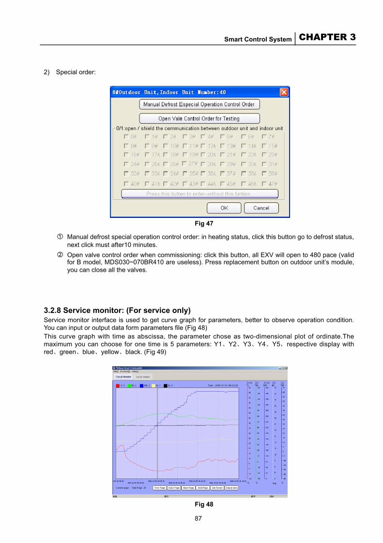
87
CHAPTER 3Smart Control System
2) Special order:
Fig 47
① Manual defrost special operation control order: in heating status, click this button go to defrost status, next click must after10 minutes.
② Open valve control order when commissioning: click this button, all EXV will open to 480 pace (valid for B model, MDS030~070BR410 are useless). Press replacement button on outdoor unit’s module, you can close all the valves.
3.2.8 Service monitor: (For service only)Service monitor interface is used to get curve graph for parameters, better to observe operation condition. You can input or output data form parameters file (Fig 48)This curve graph with time as abscissa, the parameter chose as two-dimensional plot of ordinate.The maximum you can choose for one time is 5 parameters: Y1、Y2、Y3、Y4、Y5,respective display with red、green、blue、yellow、black. (Fig 49)
Fig 48
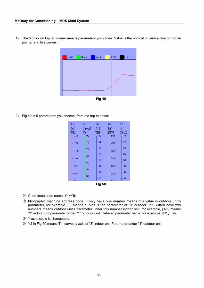
88
McQuay Air Conditioning MDS Multi System
1) The 5 color on top left corner means parameters you chose. Value is the nodical of vertical line of mouse pointer and five curves .
Fig 49
2) Fig 49 is 5 parameters you choose, from the top to down:
Fig 50
① Coordinate code name: Y1~Y5;② Idiographic machine address code, if only have one number means this value is outdoor unit's
parameter, for example, [0] means curves is the parameter of "0" outdoor unit; When have two numbers means outdoor unit's parameter under this number indoor unit, for example, [1-3] means "3" indoor unit parameter under “1” outdoor unit. Detailed parameter name, for example TH1、Tm.
③ Y-axis, scale is changeable.④ Y2 in Fig 50 means Tm curves y-axis of "3" indoor unit Parameter under "1" outdoor unit.

89
CHAPTER 3Smart Control System
3) Function button:
① Current page: it is the page of display section.② Total pages: means have all pages curve③ First page: click this button can go back to the first page’s curve④ Back page: click this button go to preceding page of current page⑤ Next page: click this button go to next page of current page⑥ End page: click this button go to the last page’s curve⑦ Set Parameter: click this button go to interface as follows (Fig 52)
Fig 51
Fig 52
4) Y1~Y5 parameter option:Outdoor unit NO.: can choose all outdoor units have been connectedIndoor unit NO.: mark “√” on indoor unit to choose this indoor unit, don’t mark “√” means you just want to choose outdoor unitDisplay: mark “√” display selective parameters,if don’t mark “√” will not display.Name: you can make user-defined nameDate item: choose any parameter in pull down menu. When you choose outdoor unit only have outdoor unit’s parameter in pull down menu; When you choose indoor unit only have indoor unit’s parameter in pull down menu Upper limit: scale maximum of Y-axis, can be changed. Lower limit: scale least of Y-axis, can be changed. Unit scale: can be changed to by hand, adjust curve to the best position.Function option: Real time monitor: display data received as curves Automatic turn page: choose this function, every time creates curve will display the last page’s curve History data: display the data of the date you want to see Input data: input file not is “* .top” formAfter choose all the parameter, click “confirm” will display curve pf the parameters⑧ Output data (Fig 53): default track is C tray root directory, can be changed, file name can not be
changed
Fig 52

90
McQuay Air Conditioning MDS Multi System
3.2.9 Fault List (For service only)■ Outdoor unit faults
a. Communication faults between indoor unit n1 and outdoor unit m1b. Digital compressor overload c. Common compressor 1 overload d. Common compressor 2 overload e.Common compressor 3 overload f. High-pressure fault g. Low-pressure fault h. Memory fault i. System fault j. High discharge temp. k. Communication fault between indoor units and outdoor units l. Four-way valve fault m. Operation forbidden in super-high/low environment temp. n. Emergent operation startupo. Super-high temp. within 2°C protection p. Refrigerant leakage q. Communication fault between the master unit and the slave unit r. High-pressure sensor fault s. Low-pressure sensor fault t. Outdoor unit “NO.n” not connected
■ Indoor unit faultsa. Coil inlet temperature sensor faultb. Coil outlet temperature sensor faultc. Coil midlet temperature sensor faultd. Return air temperature sensor fault
Note:
■ You must insert code key to USB connection when you login in, so please keep your code key properly.
■ When open the monitor software, the system will build a file named as per date time under installation directory, it’s a file with suffix “top”, this file deposit all operation data, the longest save time is 40 days, exceed 40 days will delete the data.
■ All function mentioned in above is base on monitor software is opened.

91
CHAPTER 3Smart Control System
COM 0Ethernet USB RS485 (to ModBus)
RS485 (to units)
Fuse Power supply
3.3 MC-CCS05A - MC510 Gateway
3.3.1 IntroductionMC510 Gateway Protocol can be used to facilitate the communication between the McQuay cooling/heating unit control system and the ModBus-based communication system.The gateway automatically translates the communication protocol of McQuay units into ModBus communication protocol, and ensures that the units can be connected to the ModBus-based BAS system. Here, ModBus communication protocol is a publicly released official document:
Modicon ModBus ProtocolReference GuideMarch 1992,PI-MBUS-300Rev.D
All of our protocols are based on RTU format.
3.3.2 Indication of LEDPOWER indicator: lights up when the unit is powered on.LED1 indicator (reserved)LED2 indicator (reserved)COM1 indicator: twinkles when the MC510 communicates with the BAS system.COM2 indicator: twinkles when the MC510 outdoor units are communicating.
3.3.3 Installation Considerations1. Do not operate on the gateway when it is powered on.2. Do not install the gateway near transformer cables, electromagnetic wave sources or strong power
supplies.Do not touch the electronic components while fixing jumpers. Otherwise, electric discharge might damage the components to a degree beyond reparation.
3.3.4 Power SupplyThe power supply for the gateway main-board should be 100Vac—240Vac and 50/60Hz.The rated current for the fuse is 250mA.
3.3.5 Configurations for MC5109 Gateway are As Follows:
■■■■■
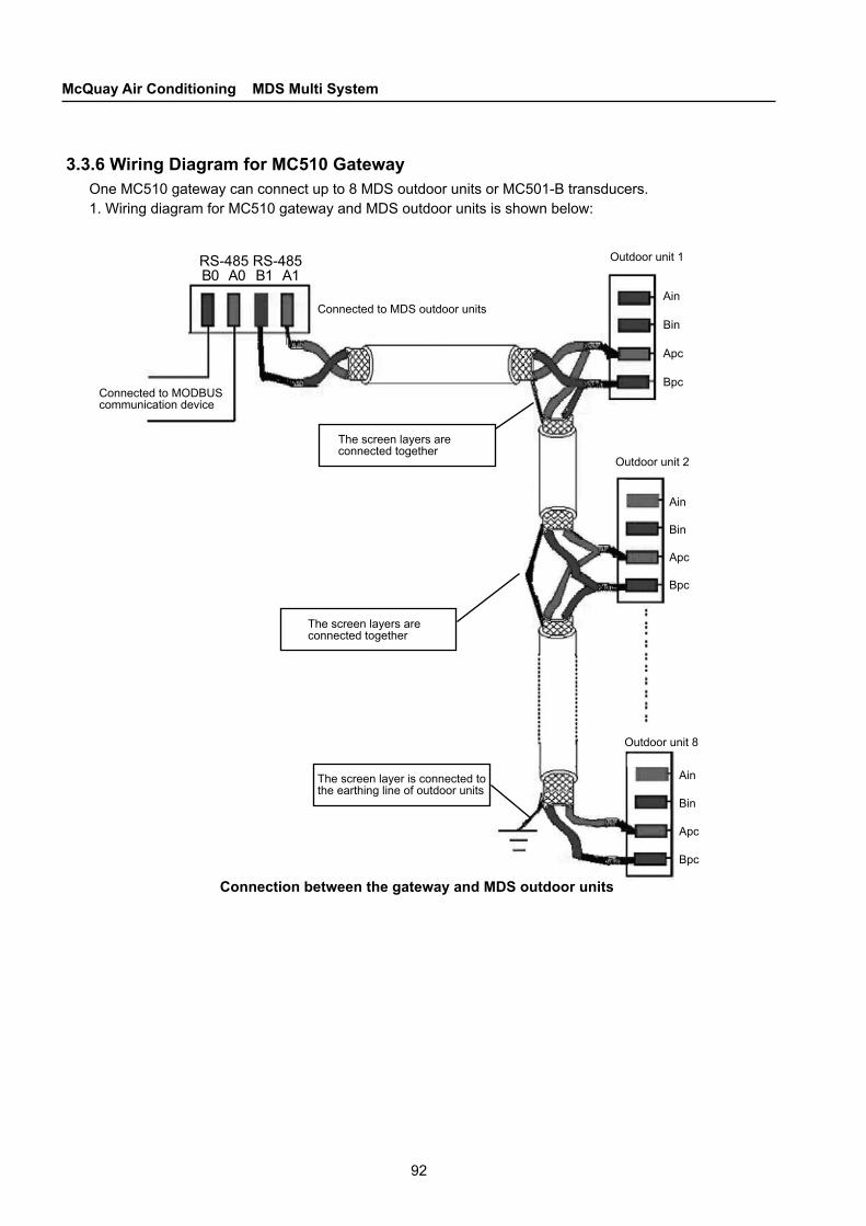
92
McQuay Air Conditioning MDS Multi System
Connected to MODBUS communication device
Connected to MDS outdoor units
The screen layers are connected together
Outdoor unit 1
Outdoor unit 8
The screen layers are connected together
The screen layer is connected to the earthing line of outdoor units
RS-485 RS-485B0 A0 B1 A1
Outdoor unit 2
3.3.6 Wiring Diagram for MC510 GatewayOne MC510 gateway can connect up to 8 MDS outdoor units or MC501-B transducers.1. Wiring diagram for MC510 gateway and MDS outdoor units is shown below:
Connection between the gateway and MDS outdoor units
Ain
Bin
Apc
Bpc
Ain
Bin
Apc
Bpc
Ain
Bin
Apc
Bpc

93
CHAPTER 3Smart Control System
2. Wiring diagram for MC510 gateway and MC501-B transformer is shown below:
The screen layers are connected together
Connected to MODBUS communication device
Connection between the gateway and MC501 controller
Connected to MC501-B
The screen layer is connected to the earthing line of outdoor units
RS-485 RS-485B0 A0 B1 A1
The screen layers are connected together
MC501-B
No. 1
No. 2
MC501-B
MC501-B
3.3.7 Requirements on Network CableThe screen layer is connected to the earthing line of outdoor unitsShielded twisted pair diagram
Printing
A B C D
Shielded twisted pair diagram
A1
B1
A2
B2
A1
B1
A2
B2
A1
B1
A2
B2

94
McQuay Air Conditioning MDS Multi System
1. The network cable is shown in the above figureA: Conductor (WTC pair with cross section area of at least 0.5mm2 or 20AWG)B: InsulatorC: Shielding layer (Twisted WTC with screening factor no less than 95%).D: Outer jacket (PVC)
2. Note:(1) Choose network cables with shielding layer as intense as possible, and with twisting distance as
small as possible.(2) You can refer to the UL2547or UL2791 wire specification. (3) The total length of all cables should not exceed 100m.
3.3.8 Application cases of MC510 and McQuay Air Conditioners1. MC510 gateway and MDS units
MC510No.0
RS-485
RS-485
RS-485
ModBus
OutdoorunitNo.0
OutdoorunitNo.1
OutdoorunitNo.7
OutdoorunitNo.0
OutdoorunitNo.1
OutdoorunitNo.7
OutdoorunitNo.0
Indoor unitNo.1
Indoor unitNo.2
Indoor unitNo.48
MDS Indoor unit: MDBX, MCK, MCM, MCC, MDB, MWM…
OutdoorunitNo.1
OutdoorunitNo.7
MC510No.1
MC510No.15
Application case 1 — MC510 and MDS units
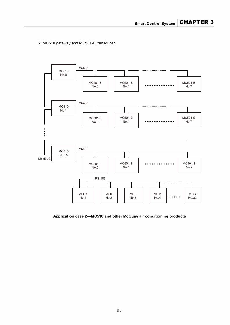
95
CHAPTER 3Smart Control System
2. MC510 gateway and MC501-B transducer
Application case 2—MC510 and other McQuay air conditioning products
MC510No.0
MC501-BNo.0
MC510No.1
MC510No.15
ModBUS
MC501-BNo.0
RS-485
RS-485
RS-485
RS-485
MC501-BNo.1
MC501-BNo.1
MC501-BNo.7
MC501-BNo.7
MC501-BNo.0
MDBXNo.1
MCKNo.2
MDBNo.3
MCMNo.4
MCCNo.32
MC501-BNo.1
MC501-BNo.7

96
McQuay Air Conditioning MDS Multi System
MC510No.0
RS-485
RS-485
RS-485
MDS Outdoor
unitNo.0
MC510No.1
MC510No.15
MC501-BNo.0
MC501-BNo.1
MC501-BNo.7
MDS Outdoor
unitNo.1
MDS Outdoor
unitNo.7
MDS Outdoor
unitNo.0
MDS Outdoor
unitNo.1
MDS Outdoor
unitNo.7
3. Mixed connection for MDS outdoor units and MC501-B transducer
Application 3—Mixed connection for MDS units and MC501-B
Presently, one MC510 gateway can connect up to 8 MDS outdoor units or MC501-B transducers. Whereas one ModBus bus system can connect up to 16 MC510 gateways. If the quantity of the outdoor units requires, you can set up another ModBus channel.
97
CHAPTER 4Selection
4.1 Load Calculation
4.1.1 Planning and CoordinationBefore the project starts, we recommend you to carry out the following estimation and planning:
Calculate the cooling/heating load (which depends on the temperature, humidity and ventilation) based on the functions of each air-conditioned area; Query the weather data, especially sunlight, wind direction and peripheral cold/heat sources in winters and summers, and other external factors that may affect the running environment of the unit, consider all the factors in the environment that are favorable to the normal running of the unit, and determine the location and position to install the unit. (For outdoor weather parameters of each large city in China, refer to Annex 2. The description on model selection in this manual is for reference only. For actual engineering, please contact a professional design academy or related construction company);Fix the project schedule, set aside the installation space of the unit, and coordinate the installation with the construction and decoration;Carry out field check to confirm the size and layout of the selected access for the air-conditioning equipment or the capacity for the bearing weight of the hoisting cable, specify the range of the auxiliary project, and determine the location of the power supply; Verify the calculation value of the design, and confirm and determine the model and specification of the unit.
4.1.2 Calculating the Cooling load of the Air-Conditioning AreaThe cooling load of the air-conditioning area is determined by the maximum value of the cooling load of each room by hours or the accumulated value of the cooling load of each room based on the size, height and purpose of each air-conditioned room. Besides, the cooling load of fresh air and the additional cooling load incurred by the ventilator, induced draft fan and wind pipe system should be added. During the actual project, the total cooling load of the air-conditioning can be estimated through the following formula:Q = F1q1 + F2q2 + … + Fnqn, in this formula, F1 —— the air-conditioning area of each calculation unit, m2.q1 —— the cooling load per unit air-conditioning area of each calculation unit, W/m2.
Annex 3(1) lists the estimation indexes and design parameters of the air-conditioning cooling load of each type of building for reference.
4.1.3 Calculating the Heating Load of the Air-Conditioning AreaThe heating load of the air-conditioning system has much to do with the thermal insulation performance of the protection structure such as the wall, door, window and roof. In addition, the cold wind from outdoor, opening frequency of the external door, and running status of the indoor appliance also have great impacts upon the cooling load of the air-conditioning system. The method
■
■
■
■
■
■
■
■
C H A P T E R
4 Design and Model Selection
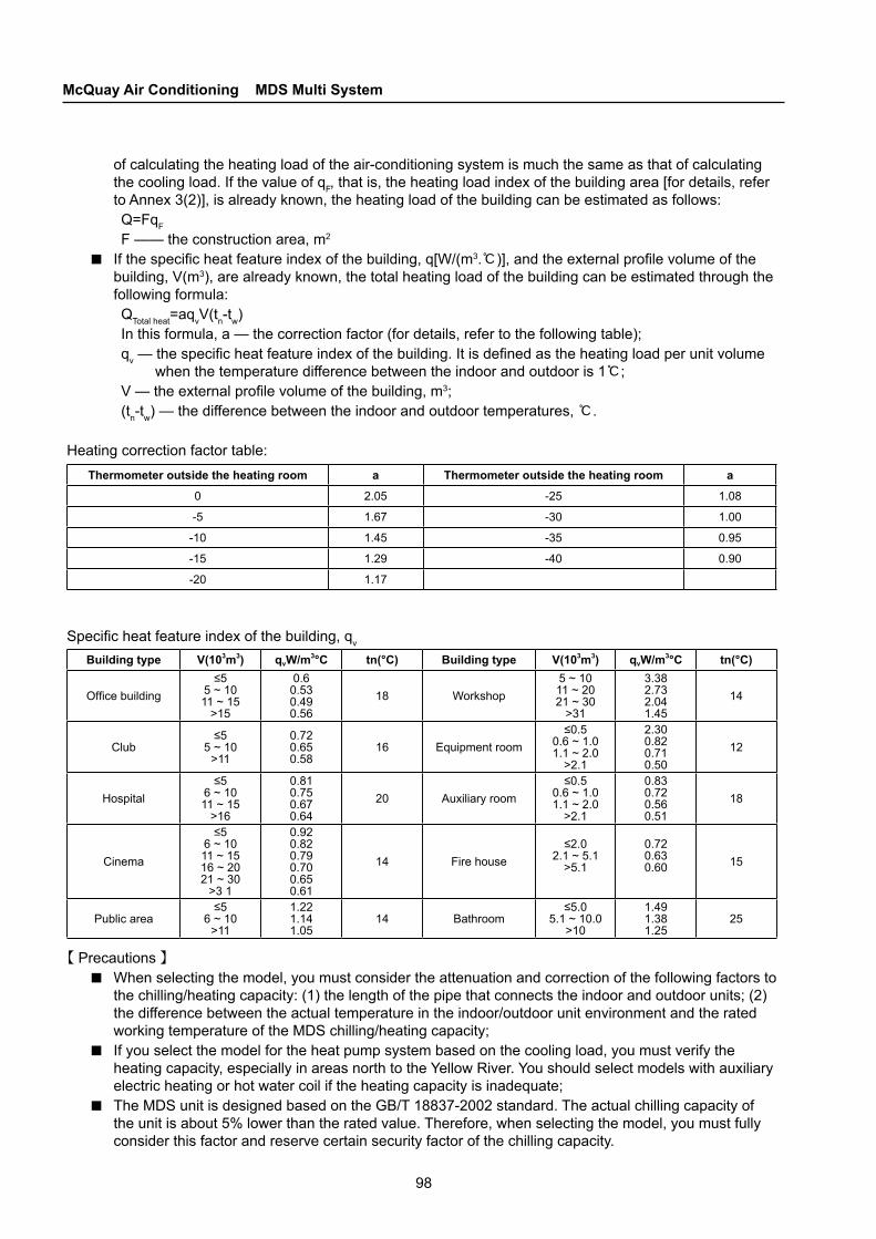
98
McQuay Air Conditioning MDS Multi System
of calculating the heating load of the air-conditioning system is much the same as that of calculating the cooling load. If the value of qF, that is, the heating load index of the building area [for details, refer to Annex 3(2)], is already known, the heating load of the building can be estimated as follows:Q=FqF
F —— the construction area, m2
If the specific heat feature index of the building, q[W/(m3.℃)], and the external profile volume of the building, V(m3), are already known, the total heating load of the building can be estimated through the following formula: QTotal heat=aqvV(tn-tw)In this formula, a — the correction factor (for details, refer to the following table);qv — the specific heat feature index of the building. It is defined as the heating load per unit volume
when the temperature difference between the indoor and outdoor is 1℃;V — the external profile volume of the building, m3;(tn-tw) — the difference between the indoor and outdoor temperatures, ℃.
Heating correction factor table:
■
Thermometer outside the heating room a Thermometer outside the heating room a
0 2.05 -25 1.08
-5 1.67 -30 1.00
-10 1.45 -35 0.95
-15 1.29 -40 0.90
-20 1.17
Specific heat feature index of the building, qv
Building type V(103m3) qvW/m3°C tn(°C) Building type V(103m3) qvW/m3°C tn(°C)
Office building≤5
5 ~ 1011 ~ 15
>15
0.60.530.490.56
18 Workshop5 ~ 1011 ~ 2021 ~ 30
>31
3.382.732.041.45
14
Club≤5
5 ~ 10>11
0.720.650.58
16 Equipment room≤0.5
0.6 ~ 1.01.1 ~ 2.0
>2.1
2.300.820.710.50
12
Hospital≤5
6 ~ 1011 ~ 15
>16
0.810.750.670.64
20 Auxiliary room≤0.5
0.6 ~ 1.01.1 ~ 2.0
>2.1
0.830.720.560.51
18
Cinema
≤56 ~ 1011 ~ 1516 ~ 2021 ~ 30
>3 1
0.920.820.790.700.650.61
14 Fire house≤2.0
2.1 ~ 5.1>5.1
0.720.630.60 15
Public area≤5
6 ~ 10>11
1.221.141.05
14 Bathroom≤5.0
5.1 ~ 10.0>10
1.491.381.25
25
【 Precautions 】When selecting the model, you must consider the attenuation and correction of the following factors to the chilling/heating capacity: (1) the length of the pipe that connects the indoor and outdoor units; (2) the difference between the actual temperature in the indoor/outdoor unit environment and the rated working temperature of the MDS chilling/heating capacity; If you select the model for the heat pump system based on the cooling load, you must verify the heating capacity, especially in areas north to the Yellow River. You should select models with auxiliary electric heating or hot water coil if the heating capacity is inadequate; The MDS unit is designed based on the GB/T 18837-2002 standard. The actual chilling capacity of the unit is about 5% lower than the rated value. Therefore, when selecting the model, you must fully consider this factor and reserve certain security factor of the chilling capacity.
■
■
■
99
CHAPTER 4Selection
4.2 Indoor Unit Model SelectionThe model for the indoor unit (flush and ceiling mounted, ceiling-embedded, open and ceiling mounted or high static pressure duct model) is selected based on the customer requirements, the indoor air flow distribution and decoration; Find out the indoor and outdoor temperatures based on the indoor unit capacity table and select an indoor unit that has a load closest to the given one. The capacity of the indoor unit should be equal to or larger than the given load;Due to the difference between the total capacities of the indoor and outdoor units, the actual running capacity may differ from the rated capacity of each indoor unit. Therefore, the actual capacity should be calculated based on the outdoor unit capacity table.
4.2.1 Selecting Models for Indoor Units of Air Duct Air Supply Air-conditionersMcQuay MCC and MDB air-cooled duct air-conditioning indoor units are classified into standard series, auxiliary electric heating series, and auxiliary hot water coil heating series.
Main factors for selecting models:● Chilling capacity/heating capacity; ● Auxiliary heating capacity (optional);● Air supply volume of indoor unit; ● Air supply plenum of indoor unit; ● Shape and size; ● Power supply and others;
Steps in selecting models:
Determine the type of air-conditioning unitYou should determine the mode and location of the air-conditioning system and specify the air-conditioning unit type (cooling only or heat pump, that is, auxiliary heating) based on the requirements and features of the air-conditioning project and the weather conditions of the local region. Generally, in regions with high temperatures all through the year (such as Southern China) that do not need heating during winters, you can select the cooling only models. In regions with distinct temperature changes, you should select the heat pump models. In regions where the temperature is low (below 0), you also need to consider heat pump models with auxiliary heating to increase the heating capacity during winters. For regions where hot water is available, you can select auxiliary hot water heating models. For regions with abundant power supply, you can select electric heating models.
Calculate the cooling load in summer QTotal cooling and the heating load in winter QTotal heating
At first, you should correctly count the load in each air-conditioned area based on the function and utilization of the building. The design load of the air-conditioner should also include the concurrency factor (≤1). Rooms with different functions and air-conditioning design modes may differ in the concurrency factor.
Determine the models and number of air-conditioning unitsThe models are selected based on the total chilling capacity in summer and verified based on the total heat load in winter. To select a model: ◆ Select the unit model and determine the total chilling capacity/sensible cooling capacity of the unit
based on the total chilling capacity, indoor and outdoor temperatures, humidity and air volume in summer.
◆ Based on the air volume and layout of the wind pipe system, determine the external static pressure desired by the system.
◆ Based on the selected model, indoor and outdoor temperatures, humidity and air volume in winter, determine and compare the heating capacity of the unit with the total amount of heat in winter. If the unit cannot meet the needs, you should select related auxiliary heating equipment or re-select the model.
■
■●
●
●
100
McQuay Air Conditioning MDS Multi System
◆ For a cooling only air-conditioning project, determine the model and number of units based on the calculated cooling load and amended cooling capacity of the unit, that is: the cooling load of the unit = amended total cooling capacity of the selected model × number of units
◆ For a heat pump air-conditioning project, determine the model and number of units in the same way as stated earlier and check the heating capacity of the unit with the heating load of the air-conditioning project based on the following formula: Heating load of the air-conditioning unit = amended total heating capacity of the selected model × number of units + (auxiliary heating capacity)
◆ Select the most economic one that can bear the cooling/heating load as the design solution. The nominal cooling/heating capacity of the unit is measured under the nominal working conditions. Under other working conditions, you need to multiply this value with a proper correction factor for calculation.
◆ Units selected based on the cooling/heating load can ensure the temperature in the room in peak load hours only. There must be adequate air volume (to ensure times of air ventilation) and comfortable air supply temperature difference to ensure necessary precision and comfort.
In design, we recommend you to:● Select the unit based on the cooling load (generally based on the sensible cooling capacity);● Verify the air volume during model selection; ● In scenarios where the latent heat load is high, you should take necessary measures for
dehumidification; ● The proper temperature difference for air supply of an air-cooled duct unit is between 12 and 14℃.
4.2.2 Operating CostsOperating costs include the electricity charge for equipment and necessary maintenance costs. The air-cooled duct air supply air-conditioner (heat pump) uses the electricity and air as the basic energy. It does not need related maintenance. Hence, the operating costs of such air-conditioners are the charge for the consumed electricity.
4.3 Outdoor Unit Model SelectionA standard combination of indoor and outdoor units refers to the value closest to the capacity of combination of outdoor units (100%).
4.3.1 Calculating Actual CapacityFind out the capacity of the outdoor unit (kW) and that of each indoor unit (kW) based on the temperatures of the given indoor and outdoor units. The formula is as follows:
IUC=OUC×(INX/TNX)IUC: the actual capacity (kW) of an indoor unitOUC: the capacity (kW) of the outdoor unit INX: the capacity index of an indoor unitTNX: total capacity of indoor units
The capacity of the indoor unit varies with the length of the refrigerant pipe. If the changed capacity is lower than the load, you need to select an indoor unit with larger capacity and repeat the selection procedure.
■
■

101
CHAPTER 4Selection
0
0
100%
100%
98.0%
98.0%
99.0%
96.0%
96.0% 95.0% 94.0% 93.0% 92.0% 90.0%
97.0%
94.0% 92.0% 91.0%
10
10
20
20
30
30
40
40
50
50 60 70 80 90 100-40
-30
-20
-10
0
0
100%
100%
97.0%
97.0%
98.5%
94.0%
95.5%
92.5% 91.0% 89.5% 88.0% 86.5%94.0%
91.0% 88.0% 86.5%10
10
20
20
30
30
40
40
50
50 60 70 80 90 100-40
-30
-20
-10Fall (m)
Pipe length (m)
Fall (m)
Fall (m)
Pipe length (m)
Fall (m)
Changes to Cooling Capacity of R410A Series Units (8-50HP)■
Changes to Heating Capacity of R22 Series Units (3-32HP)■
Changes to Heating Capacity of R410A Series Units (8-50HP)■
4.3.2 Changes to Cooling CapacityChanges to Cooling Capacity of R22 Series Units (3-32HP)■
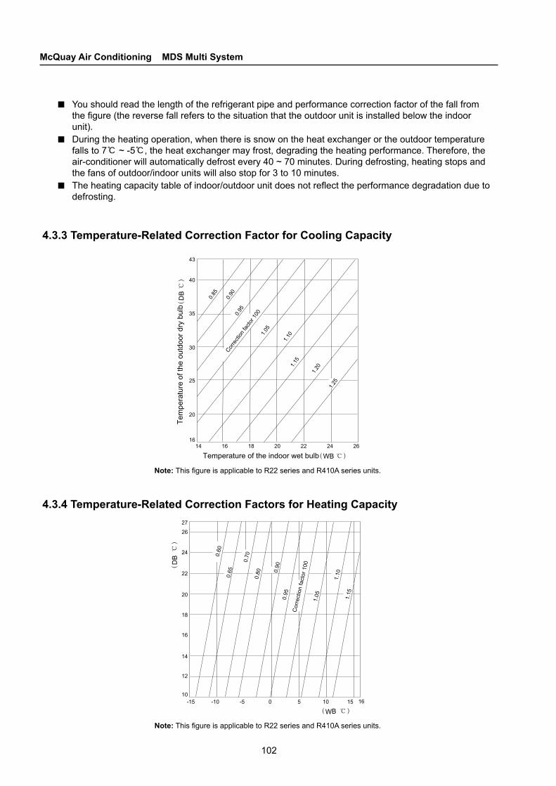
102
McQuay Air Conditioning MDS Multi System
Tem
pera
ture
of t
he o
utdo
or d
ry b
ulb
Temperature of the indoor wet bulb
Corre
ction
facto
r 100
Cor
rect
ion
fact
or 1
00
You should read the length of the refrigerant pipe and performance correction factor of the fall from the figure (the reverse fall refers to the situation that the outdoor unit is installed below the indoor unit). During the heating operation, when there is snow on the heat exchanger or the outdoor temperature falls to 7℃ ~ -5℃, the heat exchanger may frost, degrading the heating performance. Therefore, the air-conditioner will automatically defrost every 40 ~ 70 minutes. During defrosting, heating stops and the fans of outdoor/indoor units will also stop for 3 to 10 minutes. The heating capacity table of indoor/outdoor unit does not reflect the performance degradation due to defrosting.
4.3.3 Temperature-Related Correction Factor for Cooling Capacity
■
■
■
Note: This figure is applicable to R22 series and R410A series units.
4.3.4 Temperature-Related Correction Factors for Heating Capacity
Note: This figure is applicable to R22 series and R410A series units.
103
CHAPTER 4Selection
4.4 Air System DesignThe air system is an important and complex part of the air-cooled duct air-conditioning unit. The design of the air system must comply with the Specifications for Design of Heating Ventilation and Air Regulation and Fire-proof Specifications for Design of Building. To make your life more comfortable and save more energy, you need to properly design and construct the diameter of the air duct and its processing technique, air outlet, anechoic and plenum chamber, fire-proof valve, thermal insulation, and indoor air layout. The materials or data provided below serves as reference for design.
4.4.1 Selecting A Design Plan for Air Volume, Air Duct and Air VentYou need to provide the air volume based on the load indoors and the most comfortable fan speed for flexible air regulation.
Calculation in design of air vent: ● The function of the air outlet is to send the cold/hot air to the entire room or the specified air-
conditioned area, and lead and mix the indoor air to the specified temperature by producing an air flow.
● The direction and driving force of the air outlet vary with the shape and type and depend on the purpose;
● You should determine the air volume and stretch of a single air vent based on the specification parameter table in the given product catalog. You should select a model that matches the ceiling pattern and consider the noise when specifying the fan speed of the air vent. Annex 3 is for reference only.
Air supply mode of the air vent:
■
■S.N. Air supply and
return mode Applicable scope Pro and con
1 Side blow with top return
Rooms with low roofs or high depth
People stay in the air return area; the occupied space is small or null; the air vent can be freely adjusted; there are two ceiling levels or twice ceiling installation is required
2 Top blow with top return
Rooms with high ceiling for cooling in summers only
The air duct and fan coil are installed within the ceiling part, facilitating decoration;But the floor is required to be high and certain ceiling space is needed
3 Side blow with side return Rooms with low ceiling
People stay in the air return area; the fan coil does not occupy the indoor space when installed in the corridor; the direction of the air vent can be freely adjusted, but short flow easily occurs
● For the air inlet, because the conflux at the air inlet has few impacts upon the air flow in the room, the model is simple. You can install a metal grid or shutter at the hole;
● The position and shape of the air inlet depends on the air flow. If installed at the lower part of the room, the inlet bottom should be at least 0.15m higher than the floor;
● The air inlet can be simple in model as long as it is equipped with an apparatus to regulate the air volume.
The size of the air vent determines the number of air outlets and required air volume in the air-conditioned room, the air volume to be supplied from a single air outlet and the model; make sure the preset air volume does not overlap with the minimum diffusion radius. The maximum diffusion radius should cover the entire air-conditioned room. Also set aside enough vertical space, and fix the air speed at the air outlet at the maximum noise level.
■
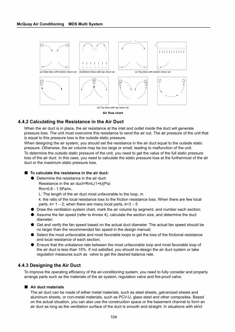
104
McQuay Air Conditioning MDS Multi System
Air flow chart
(a) Side blow with bottom return air
(d) Top blow with top return air
(b) Bottom blow with top return air (c) Top blow with bottom return air
4.4.2 Calculating the Resistance in the Air DuctWhen the air duct is in place, the air resistance at the inlet and outlet inside the duct will generate pressure loss. The unit must overcome this resistance to send the air out. The air pressure of the unit that is equal to this pressure loss is the outside static pressure. When designing the air system, you should set the resistance in the air duct equal to the outside static pressure. Otherwise, the air volume may be too large or small, leading to malfunction of the unit. To determine the outside static pressure of the unit, you need to get the value of the full static pressure loss of the air duct. In this case, you need to calculate the static pressure loss at the furthermost of the air duct or the maximum static pressure loss.
To calculate the resistance in the air duct:● Determine the resistance in the air duct:
Resistance in the air duct=RmL(1+k)(Pa)Rm=0.8 - 1.5Pa/m,
L: The length of the air duct most unfavorable to the loop, mk: the ratio of the local resistance loss to the friction resistance loss. When there are few local parts, k= 1 – 2; when there are many local parts, k=3 – 5
● Draw the ventilation system chart, mark the air volume by segment, and number each section; ● Assume the fan speed (refer to Annex 4), calculate the section size, and determine the duct
diameter; ● Get and verify the fan speed based on the actual duct diameter. The actual fan speed should be
no larger than the recommended fan speed in the design manual; ● Select the most unfavorable and most favorable loops to get the loss of the frictional resistance
and local resistance of each section; ● Ensure that the unbalance rate between the most unfavorable loop and most favorable loop of
the air duct is less than 15%. If not satisfied, you should re-design the air duct system or take regulation measures such as valve to get the desired balance rate.
4.4.3 Designing the Air DuctTo improve the operating efficiency of the air-conditioning system, you need to fully consider and properly arrange parts such as the materials of the air system, regulation valve and fire-proof valve.
Air duct materialsThe air duct can be made of either metal materials, such as steel sheets, galvanized sheets and aluminum sheets, or non-metal materials, such as PCV-U, glass steel and other composites. Based on the actual situation, you can also use the construction space or the basement channel to form an air duct as long as the ventilation surface of the duct is smooth and straight. In situations with strict
■
■
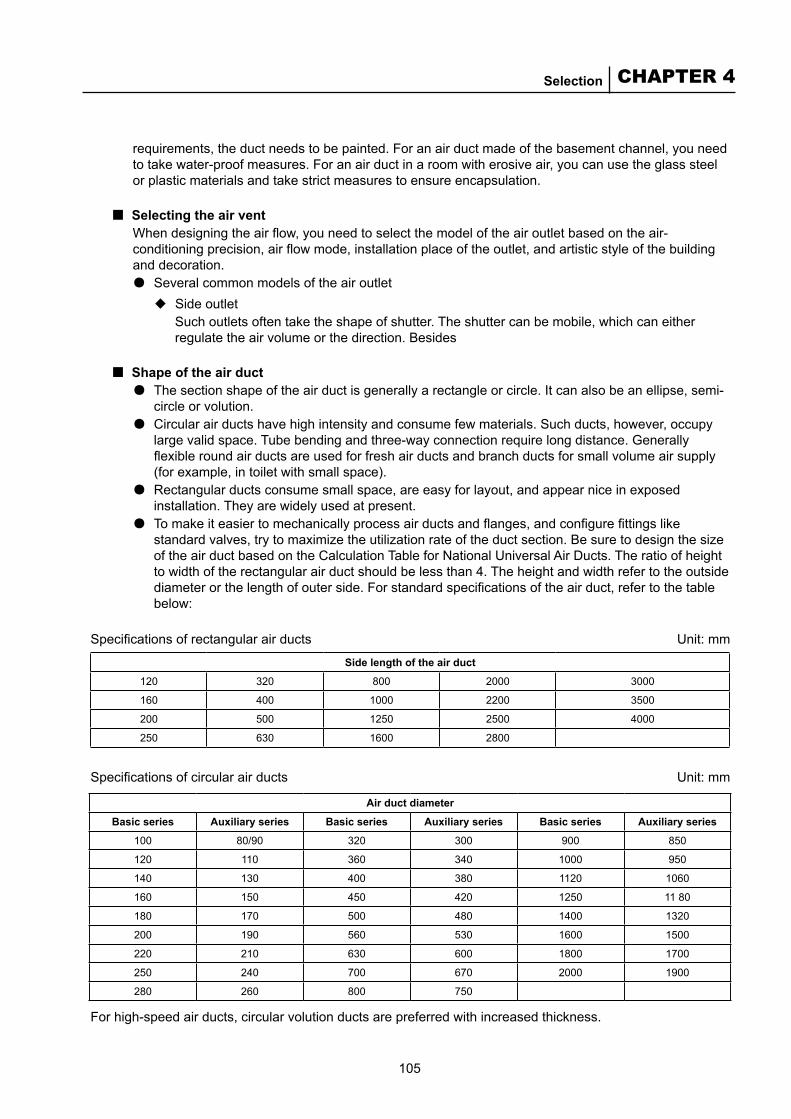
105
CHAPTER 4Selection
requirements, the duct needs to be painted. For an air duct made of the basement channel, you need to take water-proof measures. For an air duct in a room with erosive air, you can use the glass steel or plastic materials and take strict measures to ensure encapsulation.
Selecting the air ventWhen designing the air flow, you need to select the model of the air outlet based on the air-conditioning precision, air flow mode, installation place of the outlet, and artistic style of the building and decoration. ● Several common models of the air outlet
◆ Side outletSuch outlets often take the shape of shutter. The shutter can be mobile, which can either regulate the air volume or the direction. Besides
Shape of the air duct● The section shape of the air duct is generally a rectangle or circle. It can also be an ellipse, semi-
circle or volution. ● Circular air ducts have high intensity and consume few materials. Such ducts, however, occupy
large valid space. Tube bending and three-way connection require long distance. Generally flexible round air ducts are used for fresh air ducts and branch ducts for small volume air supply (for example, in toilet with small space).
● Rectangular ducts consume small space, are easy for layout, and appear nice in exposed installation. They are widely used at present.
● To make it easier to mechanically process air ducts and flanges, and configure fittings like standard valves, try to maximize the utilization rate of the duct section. Be sure to design the size of the air duct based on the Calculation Table for National Universal Air Ducts. The ratio of height to width of the rectangular air duct should be less than 4. The height and width refer to the outside diameter or the length of outer side. For standard specifications of the air duct, refer to the table below:
Specifications of rectangular air ducts Unit: mm
■
■
Side length of the air duct
120 320 800 2000 3000
160 400 1000 2200 3500
200 500 1250 2500 4000
250 630 1600 2800
Specifications of circular air ducts Unit: mm
Air duct diameter
Basic series Auxiliary series Basic series Auxiliary series Basic series Auxiliary series
100 80/90 320 300 900 850
120 110 360 340 1000 950
140 130 400 380 1120 1060
160 150 450 420 1250 11 80
180 170 500 480 1400 1320
200 190 560 530 1600 1500
220 210 630 600 1800 1700
250 240 700 670 2000 1900
280 260 800 750
For high-speed air ducts, circular volution ducts are preferred with increased thickness.

106
McQuay Air Conditioning MDS Multi System
Air pipe bend(b) Inner arc (c) Inner diagonal(a) Inner-outer arc
Wall-thickness of the air ductThe wall-thickness of the duct determines the use effect and life span. If the wall is too thin, the air duct may not be stable enough and the duct may vibrate fiercely during ventilation, increasing the noise. Together with the frictional effect, this may easily shorten the life span of the air duct, thus affecting the life span of the entire air-conditioning system.
Recommended values for thickness of steel air ducts and parts Unit: mm
■
Diameter of circular air duct or the longest side of rectangular air duct ≤320 340 ~ 450 480 ~ 630 670 ~ 1000 1120 ~ 1250 1320 ~ 2000
Rectangular air duct
Low speed duct 0.5 0.6 0.8 1.0 1.2
High speed duct 0.8 0.8 0.8 1.0 1.2
Circular air duct 0.5 0.6 0.8 1.0 1.2
Connecting mode Plugging Flange
Processing bended ductsYou can use inner arc or inner diagonal bended tubes for rectangular air ducts. When the long side A is equal to or longer than 500mm, you must set a deflector.
■
Consolidating air ductsYou can consolidate air ducts by consolidating the edge or adding a flange or reinforcement frame. When producing and installing the duct, you need to strictly abide by the latest national standard, Specifications for Construction and Acceptance of Ventilation and Air-conditioning Projects.
Accessories of the air systemAccessories of the air system mainly include air inlets and outlets, outer wall water-proof shutters, air volume regulation valves, fire-proof valves for smoke and deflectors. Before installation, you should check that the inlets and outlets of the fire smoke damper and smoke vents are flat and that the size around the neck is within the allowed range so as to closely connect to the air duct. The entire air system including accessories should be fixed and encapsulated. After installation, you should check the air system based on the low pressure air duct system. The air system should also pass the acceptance test on light or air leak.
Heat preservation of the air systemYou should use insulation materials for the insulation layer of the air duct system. For rubber plastics PE materials, they should be 25mm thick. For ordinary fiber glass materials, they should be no thinner than 35mm. The insulation layer should be flat and encapsulated. It should be closely connected with the air duct and accessories without cold bridge. Make sure the insulation layer is free from ripping.
Calculation in design of fresh air volume: The volume of fresh air depends on sanitation requirements, supplementation of local ventilation volume, and “positive pressures” in the air-conditioned room:
Sanitation requirements:In ordinary rural and urban areas, the density of carbon dioxide in the outdoor air is 0.5 - 0.75g/kg. You can use the full ventilation volume stated in the Industrial Ventilation to get the amount of fresh
■
■
■
■
●

107
CHAPTER 4Selection
air required to eliminate the carbon dioxide based on the allowed density of carbon dioxide (refer to the table below).
Allowed density of carbon dioxide (CO2)
Room typeAllowed CO2 density
L/m3 g/kg
Where people stay for long time 1.00 1.50
Where children and patients stay 0.70 1.00
Where people periodically stay (such as institutions) 1.25 1.75
Where people stay for short time 2.00 3.0
In reality, you can follow the standard: whatever the density of people in the room, provide a volume of fresh air by no less than 30m3/h.person. For densely populated buildings, such as stadiums and meeting places with air-conditioning units, where the space for each person is small and people stay for short time, provide a volume of fresh air by 7 - 15m3/h.person depending on whether people are allowed to smoke. The fresh air volume thus specified, however, generally accounts for 30 – 40% of the total air volume. In this case, the chilling capacity will be heavily burdened. Hence, you should be fully aware of the results when making such a decision.
Supplementation of local ventilation volumeWhen you set ventilation in an air-conditioned room, to avoid negative pressures in the room, there must be adequate fresh air to supply the ventilation air. Generally, for a comfortable air-conditioned room, the ventilation volume is recommended to be about 80% of the fresh air volume.
Positive pressures in the air-conditioned roomTo prevent the outside air (from outdoor or a neighboring room with low air-conditioning requirements) from interfering the temperature and humidity or reducing the purity of air in the local air-conditioned room, you need to set certain am ount of fresh air in the air-conditioning system to maintain the positive pressure in the room (that is, the atmospheric pressure indoors is higher than the pressure outdoors). Generally, a positive pressure indoors between 5Pa and 10Pa will do. A higher pressure is not only unnecessary, but also costs more. In actual design, the volume of fresh air in the system should account for over 10% of the air supply volume to make sure the air is clean and comfortable.
Introducing fresh airFresh air inlets should be installed at clean places outdoors far from the discharge outlets. You should also consider factors such as the wind directions through the year and avoid pollution sources such as smoke, dust and other harmful and poisonous substances; To prevent dust from outdoors, the bottom of a fresh air inlet should be at least 2m higher than the ground, or 1m higher than the ground when the inlet is placed in a green belt; To introduce outdoor air with relatively low temperature in summers, the inlets should be placed at the shaded side of the building. You should install the inlets at the northern wall instead of the roof or western wall; You should add accessories such as water-proof shutters, metal grids and air volume regulation valves to the fresh air inlets when necessary; To guarantee the quality and temperature of the introduced fresh air, do not install the fresh air inlets close to the outdoor unit with a condenser or the discharge outlets;The size of a fresh air inlet can be inferred from the air volume and fan speed. For the fan speed, refer to Annex 4.
【Precautions】For a heat pump unit, you should consider the impacts of floor height upon the air-conditioning results based on the actual situation. When the floor is higher than 3 meters, you should select a proper shape of inlet to improve the air flow and air-supply flow.
●
●
■●
●
●
●
●
●

108
McQuay Air Conditioning MDS Multi System
4.5 Refnet Model selection
4.5.1 Selecting Copper Pipe Models (take MDS100BR for example)
Diameters of the main pipe and terminal (equivalent length < 90m)Main pipe: Φ12.7/Φ28.6 (equal to the size of the connecting pipe of the outdoor unit)Terminal: (equal to the size of the connecting pipe of the indoor unit)
Calculate the capacity of each branch under point A A—B—C: 16.4kWA—D—E: 11.55kW
Get the pipe diameter under point A by querying the specifications of refrigerant copper pipeA—B pipe diameter: Φ12.7/Φ22.3A—D pipe diameter: Φ9.52/Φ19.05
Get the pipe diameters under points B and D in the same wayB—C pipe diameter: Φ9.52/Φ19.05D—E pipe diameter: Φ9.52/Φ15.88
4.5.2 Selecting Pipe Connector Models
Determine the specifications for pipe connectors based on the pipe diameters above and under point A (refer to the table of pipe connector specifications)
Point A pipe connector (liquid): MDS-Y2Point A pipe connector (gas): MDS-Y1
Get the specifications of pipe connectors at points B and D in the same wayPoint B pipe connector (liquid): MDS-Y2 Point C pipe connector (liquid): MDS-Y2Point B pipe connector (gas): MDS-Y4 Point C pipe connector (gas): MDS-Y4Point D pipe connector (liquid): MDS-Y2 Point E pipe connector (liquid): MDS-Y2Point D pipe connector (gas): MDS-Y4 Point E pipe connector (gas): MDS-Y1
■
■
■
■
■
■
MDS100BR
A B C
MCK020T MCC020T
MCC015T MCK020T
MCK020T
MCC010T
D E
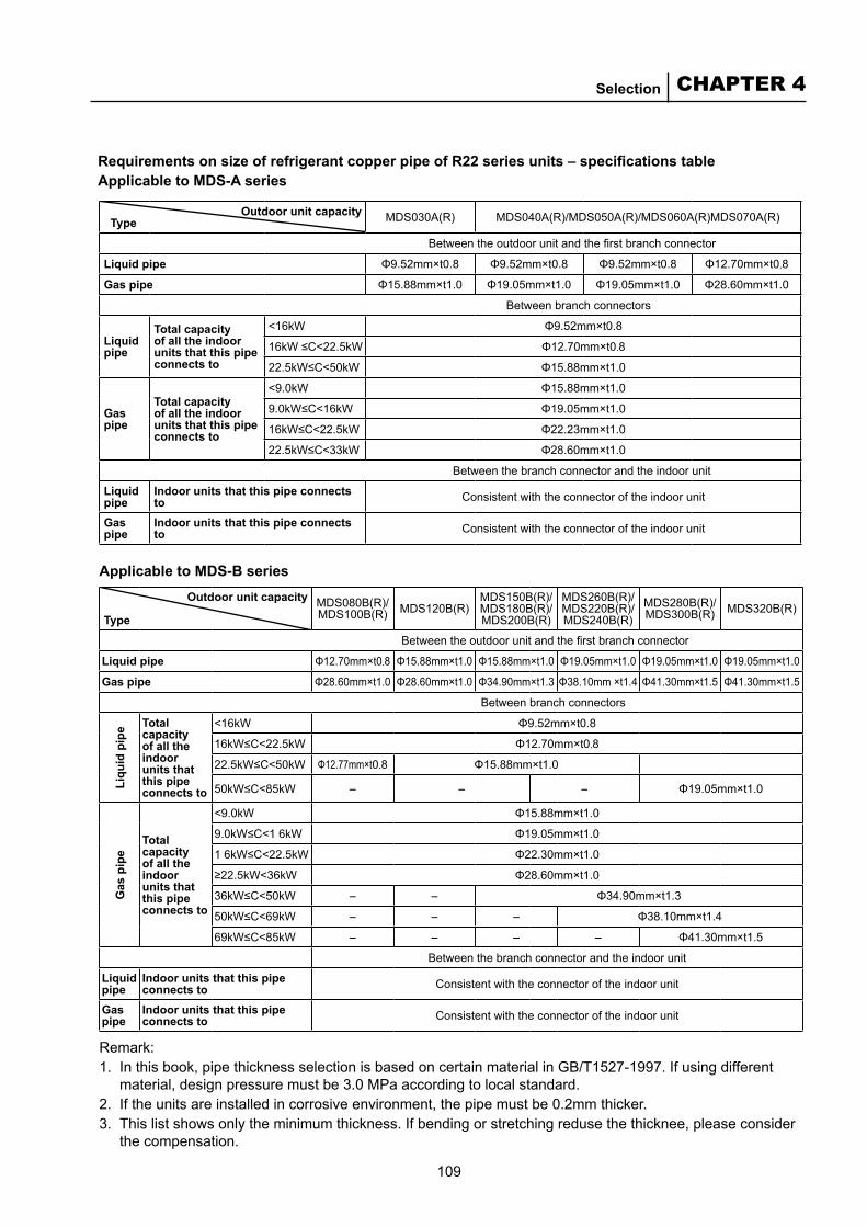
109
CHAPTER 4Selection
Requirements on size of refrigerant copper pipe of R22 series units – specifications tableApplicable to MDS-A series
Applicable to MDS-B series
Outdoor unit capacity Type MDS030A(R) MDS040A(R)/MDS050A(R)/MDS060A(R)MDS070A(R)
Between the outdoor unit and the first branch connector
Liquid pipe Φ9.52mm×t0.8 Φ9.52mm×t0.8 Φ9.52mm×t0.8 Φ12.70mm×t0.8
Gas pipe Φ15.88mm×t1.0 Φ19.05mm×t1.0 Φ19.05mm×t1.0 Φ28.60mm×t1.0
Between branch connectors
Liquid pipe
Total capacity of all the indoor units that this pipe connects to
<16kW Φ9.52mm×t0.8
16kW ≤C<22.5kW Φ12.70mm×t0.8
22.5kW≤C<50kW Φ15.88mm×t1.0
Gas pipe
Total capacity of all the indoor units that this pipe connects to
<9.0kW Φ15.88mm×t1.0
9.0kW≤C<16kW Φ19.05mm×t1.0
16kW≤C<22.5kW Φ22.23mm×t1.0
22.5kW≤C<33kW Φ28.60mm×t1.0
Between the branch connector and the indoor unit
Liquid pipe
Indoor units that this pipe connects to Consistent with the connector of the indoor unit
Gas pipe
Indoor units that this pipe connects to Consistent with the connector of the indoor unit
Outdoor unit capacity
TypeMDS080B(R)/MDS100B(R) MDS120B(R)
MDS150B(R)/MDS180B(R)/MDS200B(R)
MDS260B(R)/MDS220B(R)/MDS240B(R)
MDS280B(R)/MDS300B(R) MDS320B(R)
Between the outdoor unit and the first branch connector
Liquid pipe Φ12.70mm×t0.8 Φ15.88mm×t1.0 Φ15.88mm×t1.0 Φ19.05mm×t1.0 Φ19.05mm×t1.0 Φ19.05mm×t1.0
Gas pipe Φ28.60mm×t1.0 Φ28.60mm×t1.0 Φ34.90mm×t1.3 Φ38.10mm ×t1.4 Φ41.30mm×t1.5 Φ41.30mm×t1.5
Between branch connectors
Liqu
id p
ipe Total
capacity of all the indoor units that this pipe connects to
<16kW Φ9.52mm×t0.8
16kW≤C<22.5kW Φ12.70mm×t0.8
22.5kW≤C<50kW Φ12.77mm×t0.8 Φ15.88mm×t1.0
50kW≤C<85kW - - - Φ19.05mm×t1.0
Gas
pip
e
Total capacity of all the indoor units that this pipe connects to
<9.0kW Φ15.88mm×t1.0
9.0kW≤C<1 6kW Φ19.05mm×t1.0
1 6kW≤C<22.5kW Φ22.30mm×t1.0
≥22.5kW<36kW Φ28.60mm×t1.0
36kW≤C<50kW - - Φ34.90mm×t1.3
50kW≤C<69kW - - - Φ38.10mm×t1.4
69kW≤C<85kW - - - - Φ41.30mm×t1.5
Between the branch connector and the indoor unit
Liquid pipe
Indoor units that this pipe connects to Consistent with the connector of the indoor unit
Gas pipe
Indoor units that this pipe connects to Consistent with the connector of the indoor unit
Remark:1. In this book, pipe thickness selection is based on certain material in GB/T1527-1997. If using different
material, design pressure must be 3.0 MPa according to local standard.2. If the units are installed in corrosive environment, the pipe must be 0.2mm thicker.3. This list shows only the minimum thickness. If bending or stretching reduse the thicknee, please consider
the compensation.
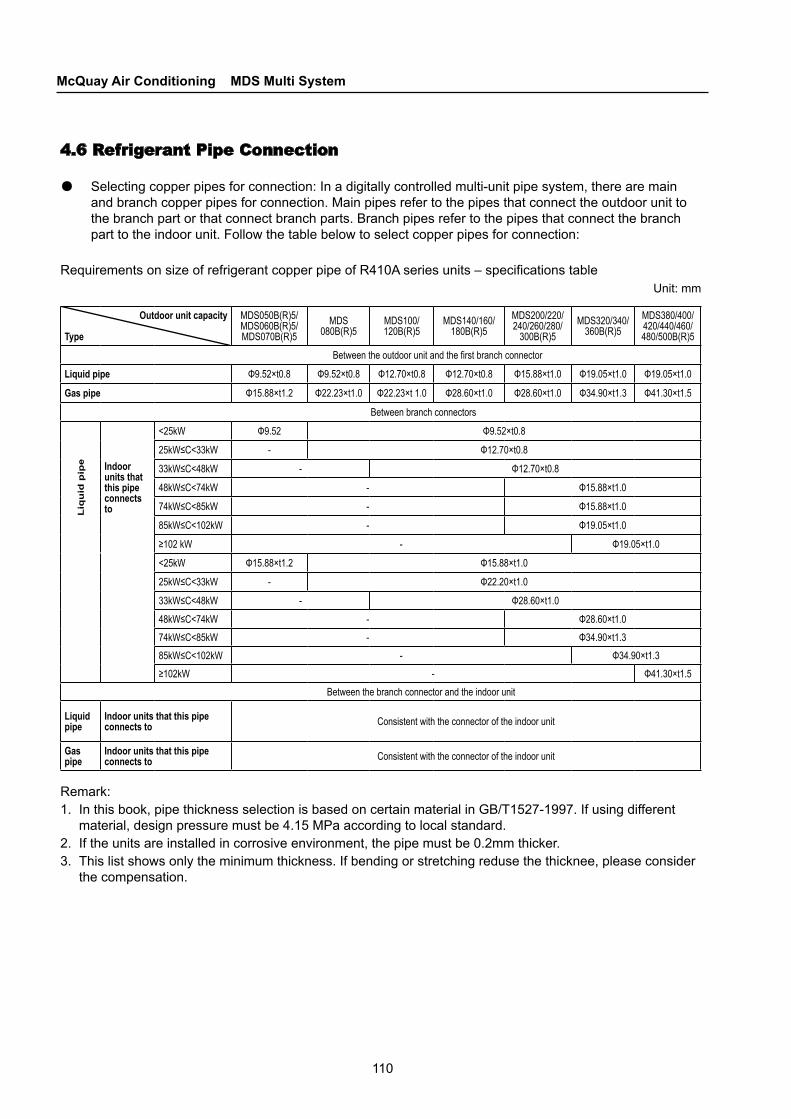
110
McQuay Air Conditioning MDS Multi System
4.6 Refrigerant Pipe Connection
● Selecting copper pipes for connection: In a digitally controlled multi-unit pipe system, there are main and branch copper pipes for connection. Main pipes refer to the pipes that connect the outdoor unit to the branch part or that connect branch parts. Branch pipes refer to the pipes that connect the branch part to the indoor unit. Follow the table below to select copper pipes for connection:
Requirements on size of refrigerant copper pipe of R410A series units – specifications tableUnit: mm
Outdoor unit capacity
Type
MDS050B(R)5/ MDS060B(R)5/ MDS070B(R)5
MDS080B(R)5
MDS100/120B(R)5
MDS140/160/180B(R)5
MDS200/220/240/260/280/
300B(R)5MDS320/340/
360B(R)5MDS380/400/420/440/460/480/500B(R)5
Between the outdoor unit and the first branch connector
Liquid pipe Φ9.52×t0.8 Φ9.52×t0.8 Φ12.70×t0.8 Φ12.70×t0.8 Φ15.88×t1.0 Φ19.05×t1.0 Φ19.05×t1.0
Gas pipe Φ15.88×t1.2 Φ22.23×t1.0 Φ22.23×t 1.0 Φ28.60×t1.0 Φ28.60×t1.0 Φ34.90×t1.3 Φ41.30×t1.5
Between branch connectors
Liq
uid
pip
e Indoor units that this pipe connects to
<25kW Φ9.52 Φ9.52×t0.8
25kW≤C<33kW - Φ12.70×t0.8
33kW≤C<48kW - Φ12.70×t0.8
48kW≤C<74kW - Φ15.88×t1.0
74kW≤C<85kW - Φ15.88×t1.0
85kW≤C<102kW - Φ19.05×t1.0
≥102 kW - Φ19.05×t1.0
<25kW Φ15.88×t1.2 Φ15.88×t1.0
25kW≤C<33kW - Φ22.20×t1.0
33kW≤C<48kW - Φ28.60×t1.0
48kW≤C<74kW - Φ28.60×t1.0
74kW≤C<85kW - Φ34.90×t1.3
85kW≤C<102kW - Φ34.90×t1.3
≥102kW - Φ41.30×t1.5
Between the branch connector and the indoor unit
Liquid pipe
Indoor units that this pipe connects to Consistent with the connector of the indoor unit
Gas pipe
Indoor units that this pipe connects to Consistent with the connector of the indoor unit
Remark:1. In this book, pipe thickness selection is based on certain material in GB/T1527-1997. If using different
material, design pressure must be 4.15 MPa according to local standard.2. If the units are installed in corrosive environment, the pipe must be 0.2mm thicker.3. This list shows only the minimum thickness. If bending or stretching reduse the thicknee, please consider
the compensation.
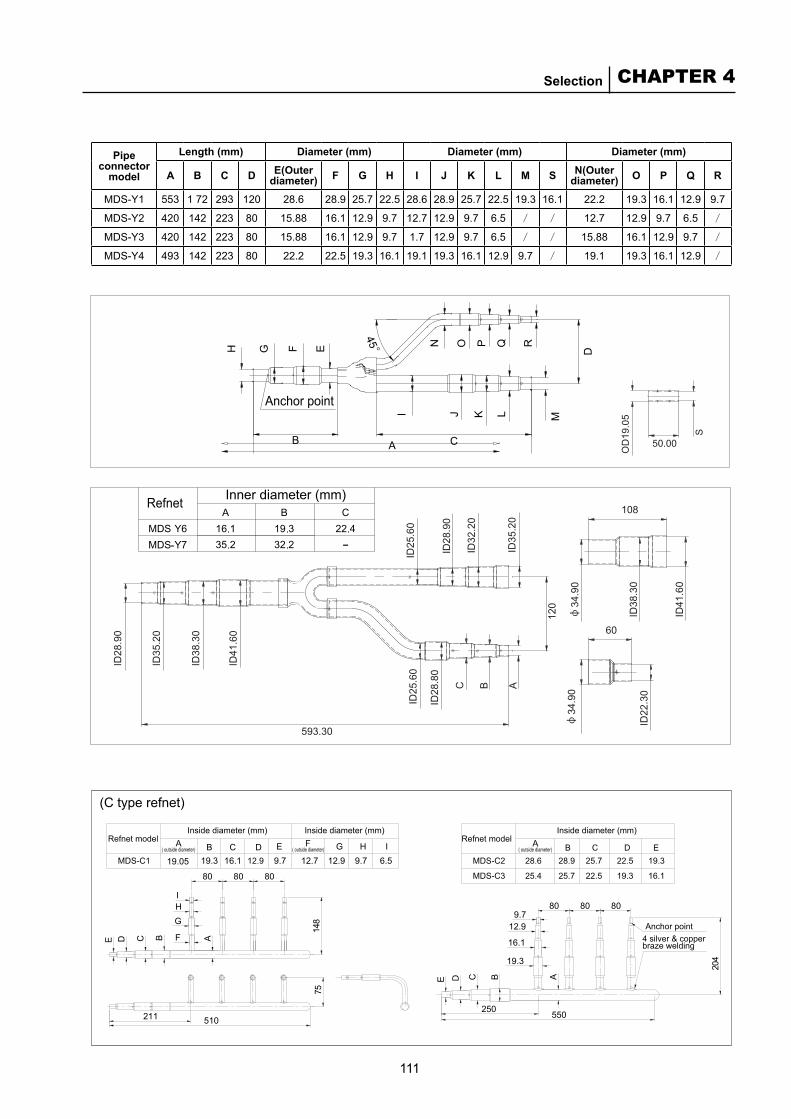
111
CHAPTER 4Selection
Inner diameter (mm)
-
Refnet
Anchor point
Pipe connector
model
Length (mm) Diameter (mm) Diameter (mm) Diameter (mm)
A B C D E(Outer diameter) F G H I J K L M S N(Outer
diameter) O P Q R
MDS-Y1 553 1 72 293 120 28.6 28.9 25.7 22.5 28.6 28.9 25.7 22.5 19.3 16.1 22.2 19.3 16.1 12.9 9.7
MDS-Y2 420 142 223 80 15.88 16.1 12.9 9.7 12.7 12.9 9.7 6.5 / / 12.7 12.9 9.7 6.5 /
MDS-Y3 420 142 223 80 15.88 16.1 12.9 9.7 1.7 12.9 9.7 6.5 / / 15.88 16.1 12.9 9.7 /
MDS-Y4 493 142 223 80 22.2 22.5 19.3 16.1 19.1 19.3 16.1 12.9 9.7 / 19.1 19.3 16.1 12.9 /
(C type refnet)
7 5
211 510
80
9.7 12.7 12.9 9.7 6.5E
8080
E D C B A
G
F
HI
19.3 16.119.05BA DC
148
G IH
C
250 550
DE
12.9
204
B A
19.3
16.1
809.7
8080
Refnet model Inside diameter (mm) Inside diameter (mm)
( outside diameter)ARefnet model
MDS-C1 MDS-C2 28.6 28.9 25.7 22.5 19.3B C D E
MDS-C3 25.4 25.7 22.5 19.3 16.1
12.9
Inside diameter (mm)
( outside diameter)F
( outside diameter)
4 silver & copper braze welding
Anchor point
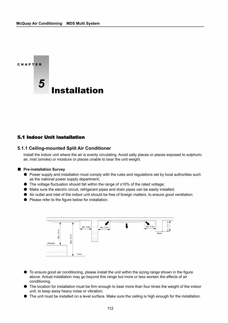
112
McQuay Air Conditioning MDS Multi System
Min. 0.5m
Min
. 1.0
m
Max
. 3.0
m
. 3m
Min. 0.5m Min. 0.5m
Obstacle
Floor
Beam
5.1 Indoor Unit Installation
5.1.1 Ceiling-mounted Split Air ConditionerInstall the indoor unit where the air is evenly circulating. Avoid salty places or places exposed to sulphuric air, mist (smoke) or moisture or places unable to bear the unit weight.
Pre-installation Survey●Power supply and installation must comply with the rules and regulations set by local authorities such
as the national power supply department; ●The voltage fluctuation should fall within the range of ±10% of the rated voltage;●Make sure the electric circuit, refrigerant pipes and drain pipes can be easily installed; ●Air outlet and inlet of the indoor unit should be free of foreign matters, to ensure good ventilation; ●Please refer to the figure below for installation.
■
●To ensure good air conditioning, please install the unit within the sizing range shown in the figure above. Actual installation may go beyond this range but more or less worsen the effects of air conditioning.
●The location for installation must be firm enough to bear more than four times the weight of the indoor unit, to keep away heavy noise or vibration;
●The unit must be installed on a level surface. Make sure the ceiling is high enough for the installation.
C H A P T E R
5 Installation
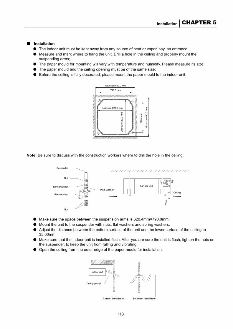
113
CHAPTER 5Installation
Unit size 820.0 mm
Uni
t siz
e 82
0.0
mm
Gap
siz
e 89
0.0
mm
Gap size 890.0 mm
790.0 mm
620.
4 m
m
Plain washerFan coil unit
Ceiling
Suspender
Nut
Nut
Spring washer
Plain washer
Indoor unit
Drainpipe clip
Correct installation Incorrect installation
Installation●The indoor unit must be kept away from any source of heat or vapor, say, an entrance;●Measure and mark where to hang the unit. Drill a hole in the ceiling and properly mount the
suspending arms; ●The paper mould for mounting will vary with temperature and humidity. Please measure its size; ●The paper mould and the ceiling opening must be of the same size; ●Before the ceiling is fully decorated, please mount the paper mould to the indoor unit.
■
●Make sure the space between the suspension arms is 620.4mm×790.0mm; ●Mount the unit to the suspender with nuts, flat washers and spring washers;●Adjust the distance between the bottom surface of the unit and the lower surface of the ceiling to
35.00mm. ●Make sure that the indoor unit is installed flush. After you are sure the unit is flush, tighten the nuts on
the suspender, to keep the unit from falling and vibrating; ●Open the ceiling from the outer edge of the paper mould for installation.
Note: Be sure to discuss with the construction workers where to drill the hole in the ceiling.
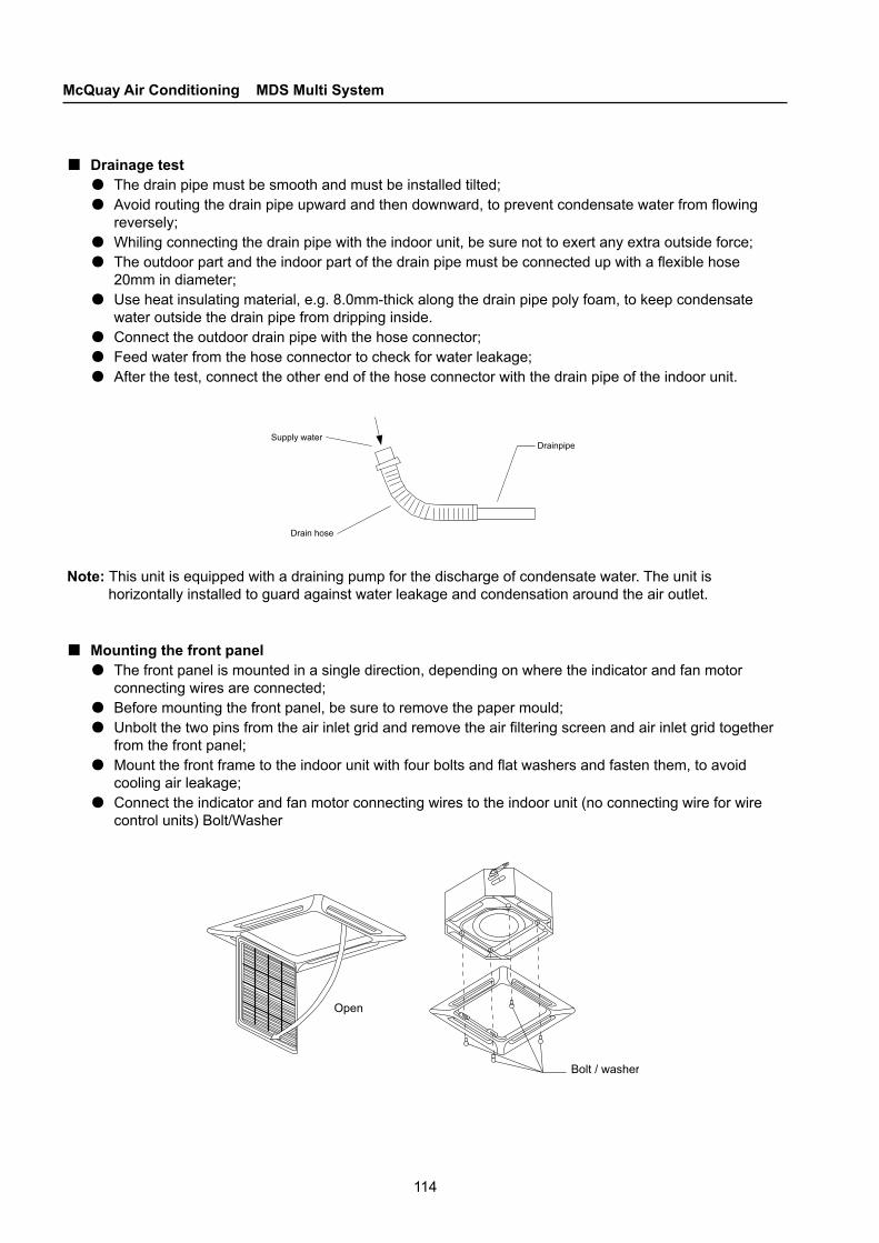
114
McQuay Air Conditioning MDS Multi System
Supply waterDrainpipe
Drain hose
Open
Bolt / washer
Drainage test●The drain pipe must be smooth and must be installed tilted; ●Avoid routing the drain pipe upward and then downward, to prevent condensate water from flowing
reversely; ●Whiling connecting the drain pipe with the indoor unit, be sure not to exert any extra outside force; ●The outdoor part and the indoor part of the drain pipe must be connected up with a flexible hose
20mm in diameter; ●Use heat insulating material, e.g. 8.0mm-thick along the drain pipe poly foam, to keep condensate
water outside the drain pipe from dripping inside. ●Connect the outdoor drain pipe with the hose connector; ●Feed water from the hose connector to check for water leakage; ●After the test, connect the other end of the hose connector with the drain pipe of the indoor unit.
■
Mounting the front panel●The front panel is mounted in a single direction, depending on where the indicator and fan motor
connecting wires are connected; ●Before mounting the front panel, be sure to remove the paper mould; ●Unbolt the two pins from the air inlet grid and remove the air filtering screen and air inlet grid together
from the front panel; ●Mount the front frame to the indoor unit with four bolts and flat washers and fasten them, to avoid
cooling air leakage; ●Connect the indicator and fan motor connecting wires to the indoor unit (no connecting wire for wire
control units) Bolt/Washer
■
Note: This unit is equipped with a draining pump for the discharge of condensate water. The unit is horizontally installed to guard against water leakage and condensation around the air outlet.
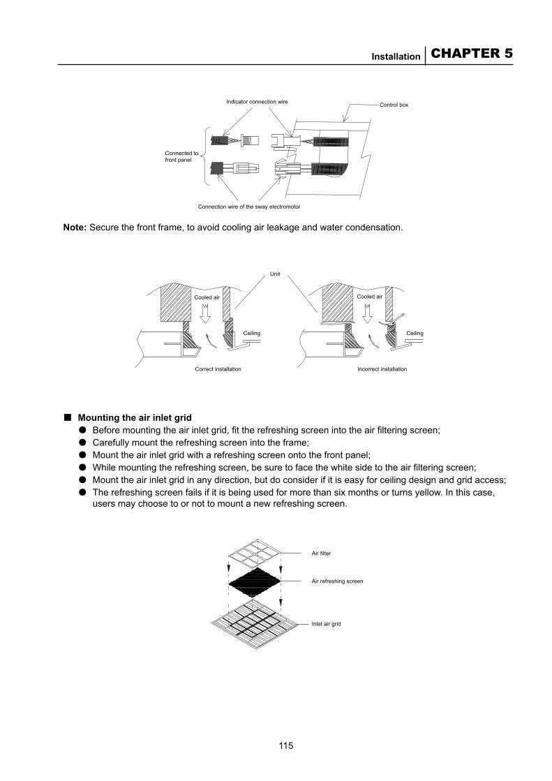
115
CHAPTER 5Installation
Control box
Connection wire of the sway electromotor
Connected to front panel
Indicator connection wire
Cooled air
Unit
Ceiling
Cooled air
Ceiling
Correct installation Incorrect installation
Air filter
Air refreshing screen
Inlet air grid
Mounting the air inlet grid●Before mounting the air inlet grid, fit the refreshing screen into the air filtering screen; ●Carefully mount the refreshing screen into the frame; ●Mount the air inlet grid with a refreshing screen onto the front panel;●While mounting the refreshing screen, be sure to face the white side to the air filtering screen; ●Mount the air inlet grid in any direction, but do consider if it is easy for ceiling design and grid access; ●The refreshing screen fails if it is being used for more than six months or turns yellow. In this case,
users may choose to or not to mount a new refreshing screen.
■
Note: Secure the front frame, to avoid cooling air leakage and water condensation.

116
McQuay Air Conditioning MDS Multi System
10m
m
Indoor unit
Bell-mouthed connector
OutletThrottle box
Liquid pipe(Throttle box) inlet
Air pipe
5.1.2 Concealed Ceiling Split Air Conditioner
Site surveyPower cables must be connected in line with local rules. For example, the national electric standard requires a voltage fluctuation within the range of ±10% of the rated voltage. The power cables must be independent from wielding the transformer circuit for the equipment. Because the transformer may result in a large voltage fluctuation, be sure that it is easy to connect and lay out wires on the installation site.
InstallationMake sure the top suspender is strong enough to bear the unit weight. Locate the suspender and check if it is aligned with the unit. Check the hanging plate to see if it is secured. Follow the instructions shown in the figure below to design the draining slope (tilted toward the drain pipe on the drain pan).
■
■
Note: Make sure system piping and air piping is the shortest. Generally these pipes are mounted in the middle; While mounting the indoor unit, make sure the air return inlet is no less than 3m away from the air supply outlet of the heat exchanger. ●Some models must go with an electronic expansion valve box (throttle box) for refrigerant piping. See
the figure on the right: ●Mounting the throttle box:
All the models in this series must connect with a throttle box for refrigerant piping, as shown in the figure below. Note: As the electronic expansion valve is located in a throttle box, mount the valve at the proper position along the liquid piping. Be sure to keep the electronic expansion valve upright. Properly mount the cable for the electronic expansion valve to the indoor unit module, to make sure the length of the cable mounted in the throttle box falls within the accepted range. See the top right figure. Mount the throttle box as shown in the figure below. Be sure that box is securely mounted. Keep the box upright as indicated in the figure.
■■
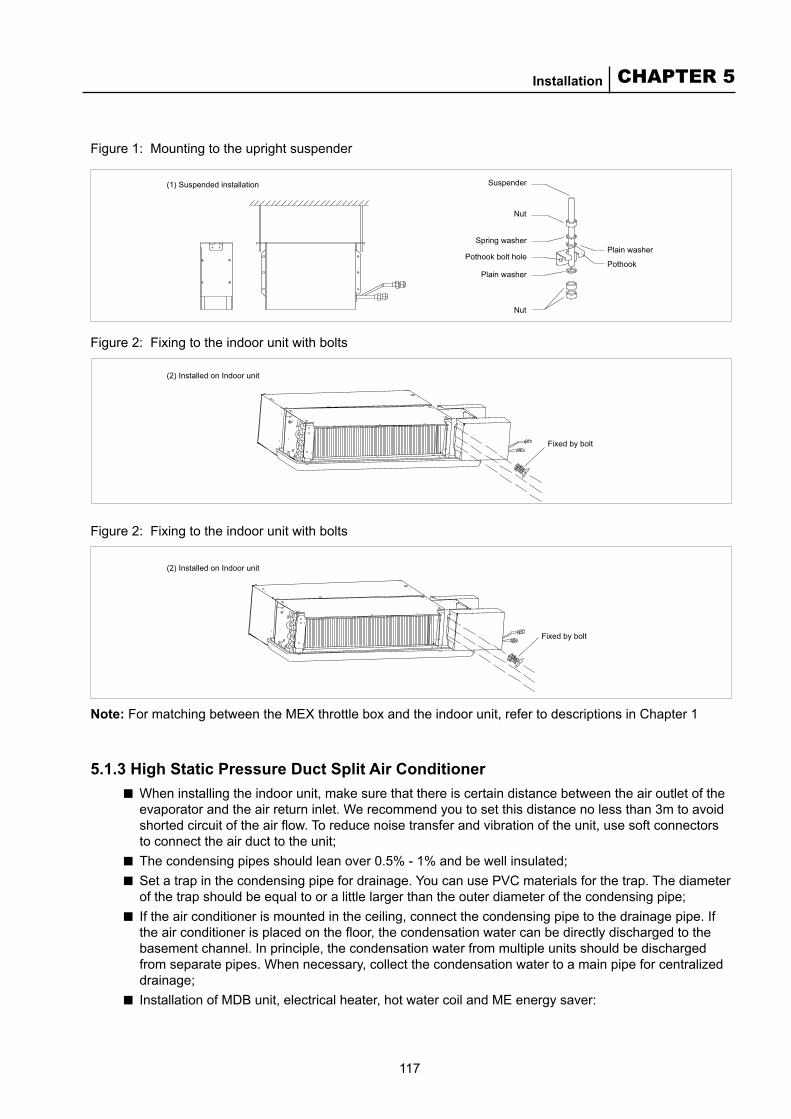
117
CHAPTER 5Installation
(1) Suspended installation Suspender
Nut
Nut
Spring washer
Pothook bolt hole
Plain washer
Plain washer
Pothook
Fixed by bolt
(2) Installed on Indoor unit
Fixed by bolt
(2) Installed on Indoor unit
Note: For matching between the MEX throttle box and the indoor unit, refer to descriptions in Chapter 1
5.1.3 High Static Pressure Duct Split Air ConditionerWhen installing the indoor unit, make sure that there is certain distance between the air outlet of the evaporator and the air return inlet. We recommend you to set this distance no less than 3m to avoid shorted circuit of the air flow. To reduce noise transfer and vibration of the unit, use soft connectors to connect the air duct to the unit; The condensing pipes should lean over 0.5% - 1% and be well insulated; Set a trap in the condensing pipe for drainage. You can use PVC materials for the trap. The diameter of the trap should be equal to or a little larger than the outer diameter of the condensing pipe; If the air conditioner is mounted in the ceiling, connect the condensing pipe to the drainage pipe. If the air conditioner is placed on the floor, the condensation water can be directly discharged to the basement channel. In principle, the condensation water from multiple units should be discharged from separate pipes. When necessary, collect the condensation water to a main pipe for centralized drainage; Installation of MDB unit, electrical heater, hot water coil and ME energy saver:
■
■■
■
■
Figure 2: Fixing to the indoor unit with bolts
Figure 2: Fixing to the indoor unit with bolts
Figure 1: Mounting to the upright suspender
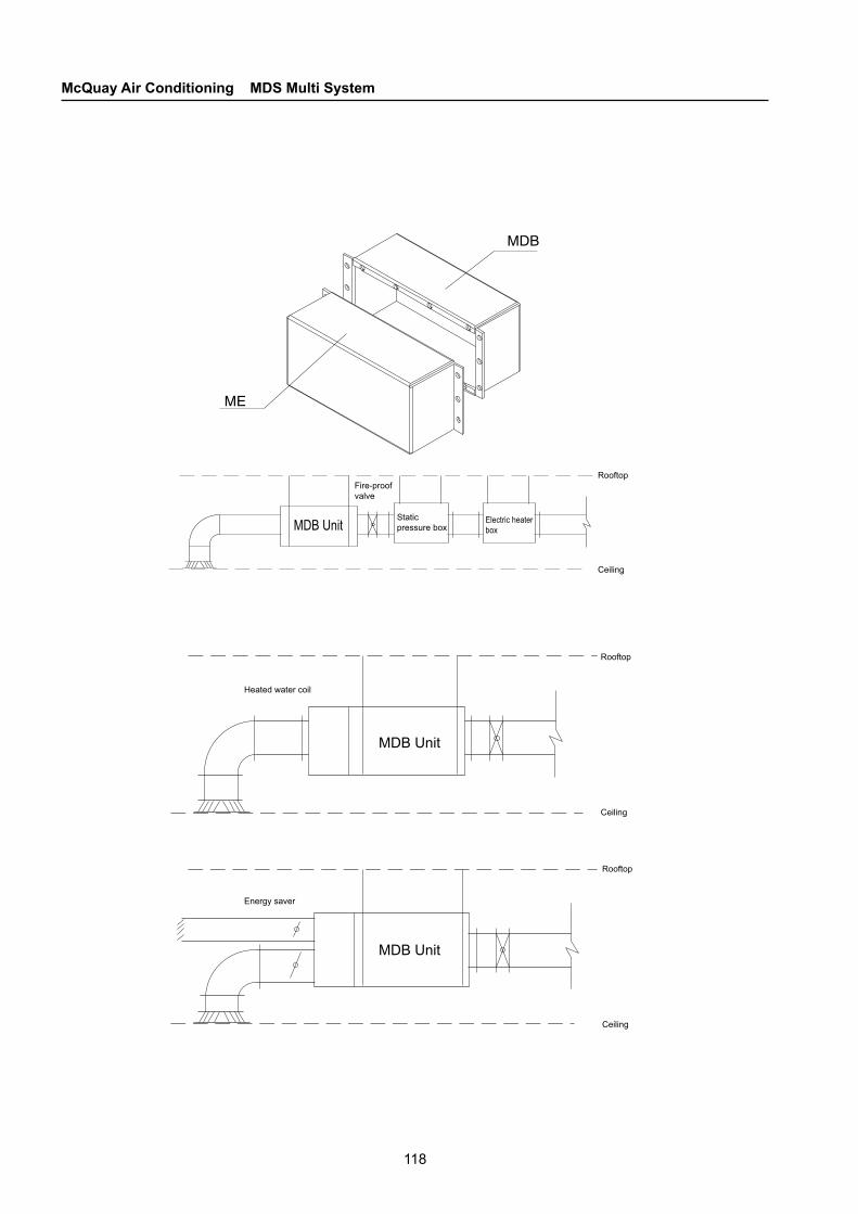
118
McQuay Air Conditioning MDS Multi System
Fire-proof valve
Static pressure box
Electric heater box
Rooftop
Ceiling
Rooftop
MDB Unit
Ceiling
Rooftop
MDB Unit
Energy saver
Heated water coil
MDB Unit
Ceiling

119
CHAPTER 5Installation
Coil section for heat water Connecting point Master unit
Outlet water
Inlet water
Protective cushio n
Hoisting cable (two)
Add supporting and lifting brackets for horizontal and vertical air ducts. Add stow-wood between the supporting and lifting brackets and the insulation layer of the insulation air duct. For the distance between supporting and lifting brackets, refer to the table below.
■
Length of the longest side of rectangular air duct (mm) ≤500 630-1000 ≥1250
Distance between supporting and lifting brackets (m) <3 <2.5 2
Mounting the hot water coilThe hot water coil is fixed with rivets or bolts at the mouth of the host air outlet valve. The connection schematic is as follows:
■
5.2 Outdoor Unit Installation
5.2.1 Hoisting Outdoor UnitFollow the figure below to hoist the outdoor unit. When moving the outdoor unit, lift the four points with supporting equipment. Do not lift three points only. Otherwise, the unit may not be well supported and thus fall.

120
McQuay Air Conditioning MDS Multi System
Note: The outdoor unit must be moved with great care.
Accessory strips cannot be used to hoist or move the unit, since they might break and cause unexpected accidents. Do not touch the heat sinks of the heat exchanger bear-handedly, since they are cutting.Dispose all plastic bags properly and keep them away from children. When the condensation temperature of the outdoor unit condenser rises, the chilling capacity will be reduced. In order to get the largest chilling capacity, you need to choose the location of the outdoor unit based on the following factors.
Make sure that the hot air through the condenser is not introduced back to the unit and that the unit does not introduce the hot air discharged by another unit. In addition, make sure there is enough space for unit maintenance; Make sure there are no obstacles on the air discharging and introducing channels; Make sure the unit is well ventilated to discharge the hot air and introduce fresh air with low temperature; The location should be strong enough to bear the weight and vibration of the unit while it is working; Avoid installing the unit in dirty, salty or sulfured places.
■
■■
■■
MDS030 - 070A/AR units ■
A B C D
Minimum distance (mm) 500 1500 300 300
Obstacle
Obstacle
Obstacle
Obstacle
Air intake
Maintenance space
Outlet air
Air intake
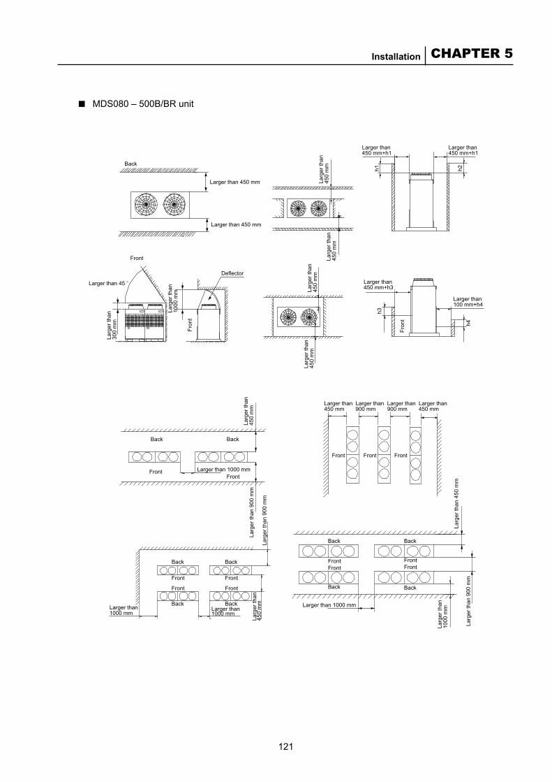
121
CHAPTER 5Installation
Back
Larger than 450 mmFr
ont
Fron
t
h3
h4
Front
Larger than 45
Deflector
Front
Back Back
Front FrontFront Front
Front Front Front
Back Back
Back Back
Larger than 1000 mm
Larg
er th
an 9
00 m
m
Larg
er th
an 9
00 m
m
Larg
er th
an 4
50 m
m
Larg
er th
an 9
00 m
m
Larg
er th
an
1000
mm
Larg
er th
an
450
mm
Front
Front
Back
Back
Front
Front
Back
BackLarger than 1000 mm
Larger than 1000 mm
Larger than 1000 mmFront
Larg
er th
an
300
mm
Larg
er th
an
1000
mm
Larg
er th
an
450
mm
Larg
er th
an
450
mm
Larg
er th
an
450
mm
Larg
er th
an
450
mm
Larg
er th
an
450
mm
Larger than 450 mm+h3
Larger than 100 mm+h4
Larger than 450 mm
Larger than 450 mm
Larger than 900 mm
Larger than 900 mm
Larger than 450 mm
Larger than 450 mm+h1
Larger than 450 mm+h1
h2h1
MDS080 – 500B/BR unit■
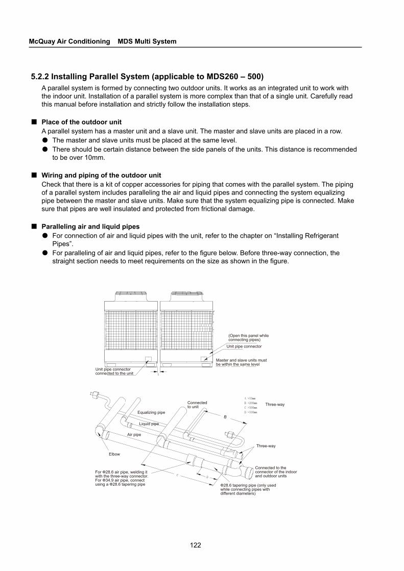
122
McQuay Air Conditioning MDS Multi System
Equalizing pipe
Liquid pipe
Air pipe
For Ф28.6 air pipe, welding it with the three-way connector. For Ф34.9 air pipe, connect using a Ф28.6 tapering pipe
Elbow
Connected to the connector of the indoor and outdoor units
Three-way
Three-way
B
Ф28.6 tapering pipe (only used while connecting pipes with different diameters)
Connected to unit
Unit pipe connector connected to the unit
(Open this panel while connecting pipes)
Master and slave units must be within the same level
Unit pipe connector
5.2.2 Installing Parallel System (applicable to MDS260 – 500)A parallel system is formed by connecting two outdoor units. It works as an integrated unit to work with the indoor unit. Installation of a parallel system is more complex than that of a single unit. Carefully read this manual before installation and strictly follow the installation steps.
Place of the outdoor unitA parallel system has a master unit and a slave unit. The master and slave units are placed in a row. ●The master and slave units must be placed at the same level. ●There should be certain distance between the side panels of the units. This distance is recommended
to be over 10mm.
Wiring and piping of the outdoor unitCheck that there is a kit of copper accessories for piping that comes with the parallel system. The piping of a parallel system includes paralleling the air and liquid pipes and connecting the system equalizing pipe between the master and slave units. Make sure that the system equalizing pipe is connected. Make sure that pipes are well insulated and protected from frictional damage.
Paralleling air and liquid pipes●For connection of air and liquid pipes with the unit, refer to the chapter on “Installing Refrigerant
Pipes”. ●For paralleling of air and liquid pipes, refer to the figure below. Before three-way connection, the
straight section needs to meet requirements on the size as shown in the figure.
■
■
■
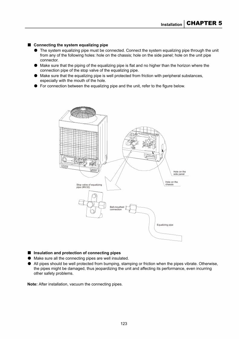
123
CHAPTER 5Installation
Stop valve of equalizing pipe (Ф9.52)
Bell-mouthed connection
Equalizing pipe
Hole on the side panel
Hole on the chassis
Connecting the system equalizing pipe●The system equalizing pipe must be connected. Connect the system equalizing pipe through the unit
from any of the following holes: hole on the chassis; hole on the side panel; hole on the unit pipe connector.
●Make sure that the piping of the equalizing pipe is flat and no higher than the horizon where the connection pipe of the stop valve of the equalizing pipe.
●Make sure that the equalizing pipe is well protected from friction with peripheral substances, especially with the mouth of the hole.
●For connection between the equalizing pipe and the unit, refer to the figure below.
■
Insulation and protection of connecting pipes●Make sure all the connecting pipes are well insulated. ●All pipes should be well protected from bumping, stamping or friction when the pipes vibrate. Otherwise,
the pipes might be damaged, thus jeopardizing the unit and affecting its performance, even incurring other safety problems.
Note: After installation, vacuum the connecting pipes.
■

124
McQuay Air Conditioning MDS Multi System
5.3 Design and Installation of Refrigerant Pipes
5.3.1 Designing Refrigerant Piping (including selection of branch connectors)
Capacity combinationThe combination ratio of indoor unit to outdoor unit in a capacity variable and multi-unit system should satisfy the following conditions:
■
Note: We recommend a value of no less than 100%. A value of higher than 100% applies to scenarios where the concurrency factor is small.
Restrictions on length of refrigerant pipeApplicable to R22 series units (Refer to the figure on P238)
■
50%≤ ≤120%∑nominal cooling capacity of the indoor unit∑nominal cooling capacity of the outdoor unit
Allowed value Pipe
Pipe
Total pipe length (actual length) ≤250m L1 + L2 + …… + Li
Max. pipe length (m)Actual length ≤125m
L1 + L3 + …… + LiEquivalent length ≤150m
Relative length from the first node to the farthest pipe L (m) ≤ 40m L3 + L4 + …… + Li
FallFall between the indoor unit and outdoor unit
When the outdoor unit is above the indoor unit ≤50m -
When the outdoor unit is below the indoor unit ≤40m -
Fall between the indoor unit and outdoor unit ≤15m -
Note: Relative length is inferred by assuming 0.5m/pipe connector and 1.0m/pipe header. The data in the table takes 8HP/10HP for example.
Applicable to R410 series unitsAllowed value Pipe
Pipe
Total pipe length (actual length) ≤350m L1 + L2 + …… + Li
Max. pipe length (m)Actual length ≤175m
L1 + L3 + …… + LiEquivalent length ≤200m
Distance from the first node to the farthest pipe L (m) ≤ 40m L3 + L4 + …… + Li
FallFall between the indoor unit and outdoor unit
When the outdoor unit is above the indoor unit ≤50m -
When the outdoor unit is below the indoor unit ≤40m -
Fall between the indoor unit and outdoor unit ≤15m -
Note: Relative length is inferred by assuming 0.5m/pipe connector and 1.0m/pipe header. The data in the table takes 8HP/10HP for example.
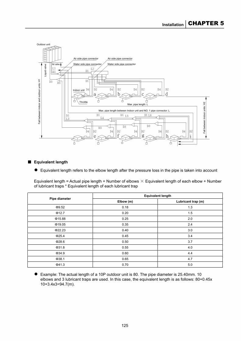
125
CHAPTER 5Installation
Air side pipe connector
Water side pipe connector
Air side pipe connector
Water side pipe connector
Fall
betw
een
Indo
or u
nits
: H2
Max. pipe length between Indoor unit and NO. 1 pipe connector: L
Max. pipe length: L
Indoor unit
Air valve
Outdoor unitLi
quid
val
ve
Fall
betw
een
indo
or a
nd o
utdo
or u
nits
: H1
Throttle
Equivalent length
Equivalent length refers to the elbow length after the pressure loss in the pipe is taken into account
Equivalent length = Actual pipe length + Number of elbows × Equivalent length of each elbow + Number of lubricant traps * Equivalent length of each lubricant trap
■●
Pipe diameterEquivalent length
Elbow (m) Lubricant trap (m)
Φ9.52 0.18 1.3
Φ12.7 0.20 1.5
Φ15.88 0.25 2.0
Φ19.05 0.35 2.4
Φ22.23 0.40 3.0
Φ25.4 0.45 3.4
Φ28.6 0.50 3.7
Φ31.8 0.55 4.0
Φ34.9 0.60 4.4
Φ38.1 0.65 4.7
Φ41.3 0.70 5.0
Example: The actual length of a 10P outdoor unit is 80. The pipe diameter is 25.40mm. 10 elbows and 3 lubricant traps are used. In this case, the equivalent length is as follows: 80+0.45x 10+3.4x3=94.7(m).
●

126
McQuay Air Conditioning MDS Multi System
Outdoor unit
Branch connector
Controller
Indoor unit
Applications of equivalent length●When the equivalent length exceeds 90% of the maximum actual length (for 6HP, it is 63m; for
8/10HP, it is 90m), the air pipe diameter of the main pipe (from the outdoor unit to the first branch pipe) needs to be a level larger. For example, when the equivalent length of a 10HP outdoor unit exceeds 90m, the diameter of the air pipe increases from 28.6mm to 31.8mm.
●When the air pipe diameter increases, you need to re-calculate the valid equivalent length. When calculating the degree of performance degradation due to the pipe length based on the drawing, use the valid equivalent length of the pipe length.
Valid equivalent length = Equivalent length of the main pipe * 0.5 + Equivalent length after the branch (when the air pipe diameter of the main pipe increases)
Example: The actual pipe length of a 10HP outdoor unit is 80m. The equivalent length after the branch pipe is 20m. The air pipe diameter of the main pipe is 25.40mm. 10 elbows and 3 lubricant traps are used (suppose they are all used inside the main pipe). ●Equivalent length: 80+0.45×10+3.4×3=94.7(m)●Since the equivalent length exceeds 90m, the air pipe diameter of the main pipe needs to be
increased. ●Valid equivalent length = (60+0.45*10+3.4*3)*0.5+20=59.1(m)● In this case, when the air pipe diameter of the main pipe increases, the performance loss due to
lengthened pipe equals to an equivalent length of 59.1m.
Branch connector only/branch pipe connection only
■
■
■
Connector-only connection

127
CHAPTER 5Installation
Outdoor unit
Outdoor unit
Branch connector
Branch header
Indoor unit
Controller
Branch pipe connection only
Combination of branch connector and branch pipe
Branch header
Controller
Horizontal line
Horizontal line
Or
View from direction B
View from direction A
A
B
Within ±3°
Within ±3°
Precautions in piping
Only use the pipe with specified diameter for a refrigerant pipe;
Mount the pipe connectors vertically.
■●●
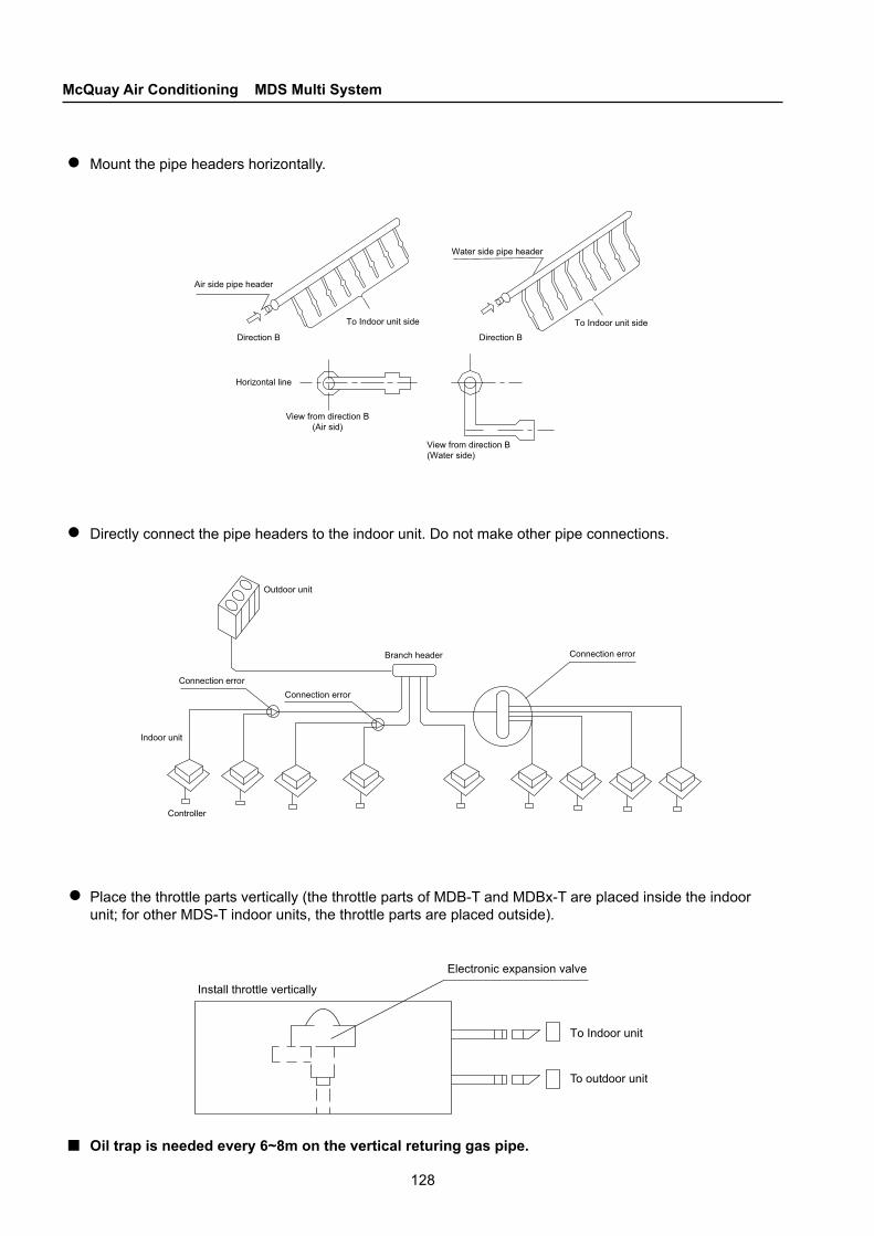
128
McQuay Air Conditioning MDS Multi System
Air side pipe header
Direction B
Horizontal line
View from direction B(Air sid)
To Indoor unit side
Water side pipe header
To Indoor unit side Direction B
View from direction B(Water side)
Connection error
Connection errorConnection error
Outdoor unit
Branch header
Indoor unit
Controller
Install throttle vertically
Electronic expansion valve
To Indoor unit
To outdoor unit
Mount the pipe headers horizontally. ●
Directly connect the pipe headers to the indoor unit. Do not make other pipe connections. ●
Place the throttle parts vertically (the throttle parts of MDB-T and MDBx-T are placed inside the indoor unit; for other MDS-T indoor units, the throttle parts are placed outside).
●
Oil trap is needed every 6~8m on the vertical returing gas pipe. ■
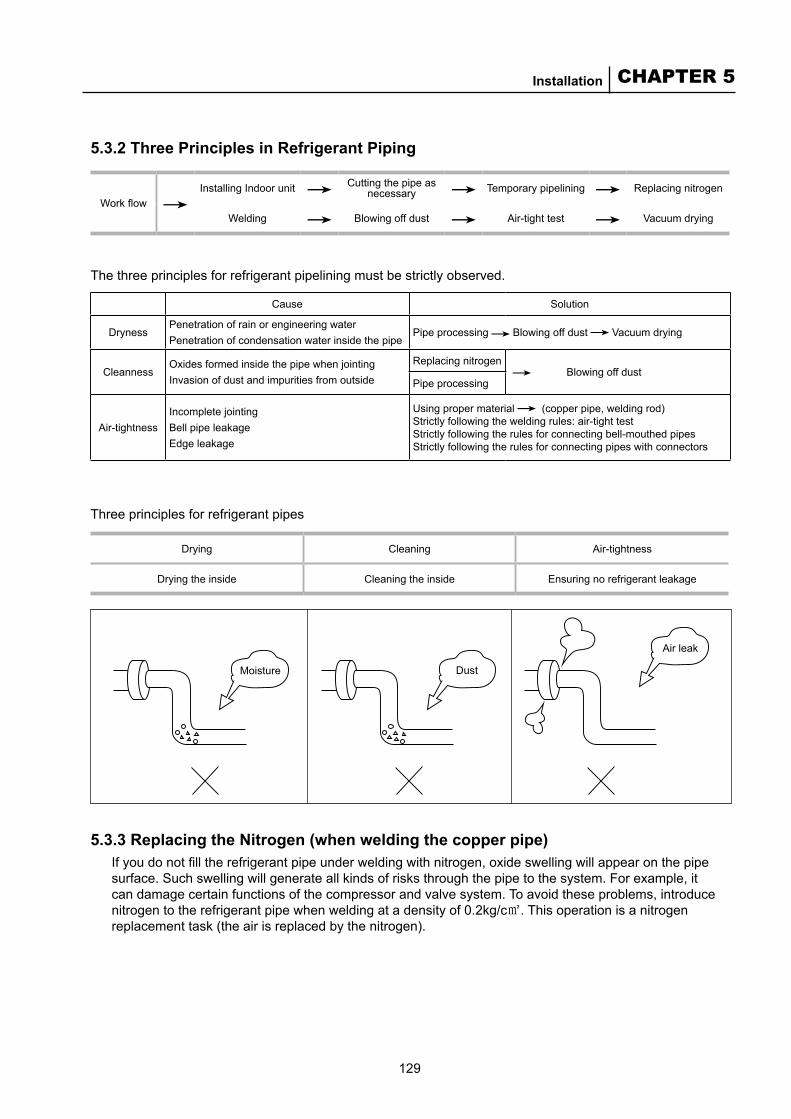
129
CHAPTER 5Installation
Dust
Air leak
Moisture
5.3.2 Three Principles in Refrigerant Piping
Cause Solution
DrynessPenetration of rain or engineering waterPenetration of condensation water inside the pipe
Pipe processing Blowing off dust Vacuum drying
CleannessOxides formed inside the pipe when jointingInvasion of dust and impurities from outside
Replacing nitrogen Blowing off dust
Pipe processing
Air-tightnessIncomplete jointingBell pipe leakageEdge leakage
Using proper material (copper pipe, welding rod)Strictly following the welding rules: air-tight testStrictly following the rules for connecting bell-mouthed pipes Strictly following the rules for connecting pipes with connectors
Three principles for refrigerant pipes
5.3.3 Replacing the Nitrogen (when welding the copper pipe)If you do not fill the refrigerant pipe under welding with nitrogen, oxide swelling will appear on the pipe surface. Such swelling will generate all kinds of risks through the pipe to the system. For example, it can damage certain functions of the compressor and valve system. To avoid these problems, introduce nitrogen to the refrigerant pipe when welding at a density of 0.2kg/c㎡. This operation is a nitrogen replacement task (the air is replaced by the nitrogen).
Work flowInstalling Indoor unit Cutting the pipe as
necessary Temporary pipelining Replacing nitrogen
Welding Blowing off dust Air-tight test Vacuum drying
The three principles for refrigerant pipelining must be strictly observed.
Drying Cleaning Air-tightness
Drying the inside Cleaning the inside Ensuring no refrigerant leakage

130
McQuay Air Conditioning MDS Multi System
High pressure pipe
Welding areaBandage
Pipe
Nitrogen cylinder Helium
cylinder
Non-hermetic valve
Copper pipeEquipment pipe
Pressure adjuster
Pressure adjuster
Non-hermetic valve
Pipe
Outdoor unit
Copper pipe
Flatten
Welding area
Welded
Open terminal
Copper pipe
PVC beltBending beltReturn belt to the starting point Twist a few
more loops
Pipe plug
Outdoor Indoor
Spare pipes must also be plugged
It is a standard practice in welding.
Key points:■The gas must be nitrogen. Neither carbon oxide nor Freon is appropriate, while oxygen is forbidden
because it causes dangers. ■Use a pressure regulator.
5.3.4 Transporting and Preserving Pipes■Make sure the pipes are not bended or distorted in transportation. Cover pipe caps to keep the pipes
away from unwanted things or rain. Seal the terminals of each pipe for preservation. You can joint or wrap the terminals, as shown in the figure below:
■Pay special attention to the following operations:●Make holes on the copper pipe (unwanted things can easily get into the pipe). ●Leave the copper pipe outdoors (the rain may easily get into the pipe).
(Pay special attention when the pipe stands vertical outdoors.)
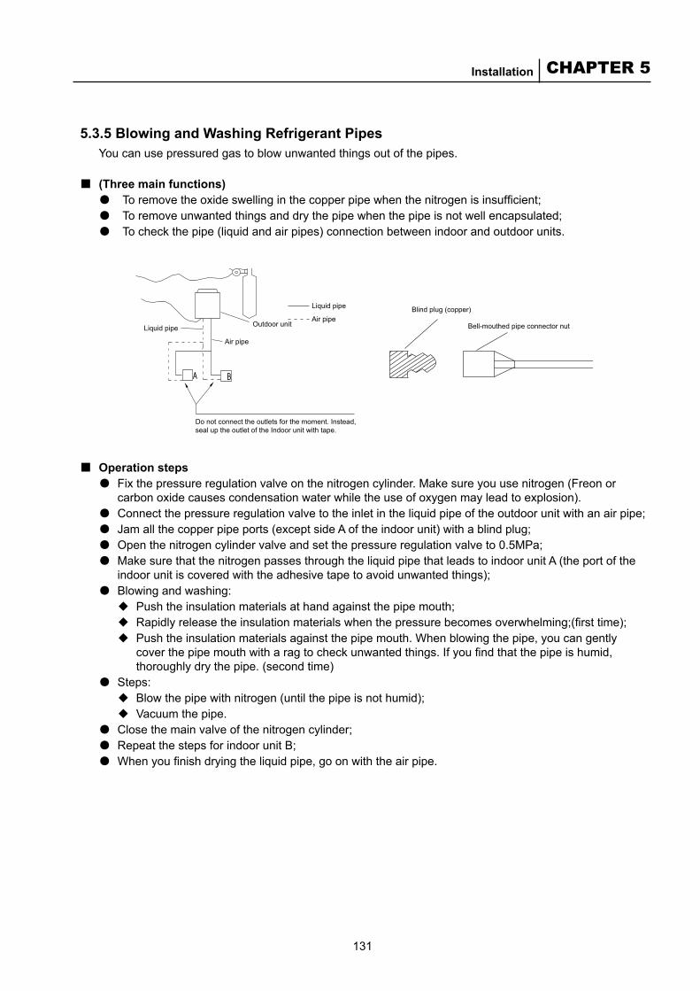
131
CHAPTER 5Installation
Liquid pipe
Air pipe
Do not connect the outlets for the moment. Instead, seal up the outlet of the Indoor unit with tape.
Liquid pipe
Air pipe
Outdoor unit
Blind plug (copper)
Bell-mouthed pipe connector nut
5.3.5 Blowing and Washing Refrigerant PipesYou can use pressured gas to blow unwanted things out of the pipes.
(Three main functions)● To remove the oxide swelling in the copper pipe when the nitrogen is insufficient; ● To remove unwanted things and dry the pipe when the pipe is not well encapsulated; ● To check the pipe (liquid and air pipes) connection between indoor and outdoor units.
■
Operation steps● Fix the pressure regulation valve on the nitrogen cylinder. Make sure you use nitrogen (Freon or
carbon oxide causes condensation water while the use of oxygen may lead to explosion). ● Connect the pressure regulation valve to the inlet in the liquid pipe of the outdoor unit with an air pipe; ● Jam all the copper pipe ports (except side A of the indoor unit) with a blind plug; ● Open the nitrogen cylinder valve and set the pressure regulation valve to 0.5MPa; ● Make sure that the nitrogen passes through the liquid pipe that leads to indoor unit A (the port of the
indoor unit is covered with the adhesive tape to avoid unwanted things); ● Blowing and washing:
◆Push the insulation materials at hand against the pipe mouth; ◆Rapidly release the insulation materials when the pressure becomes overwhelming;(first time);◆ Push the insulation materials against the pipe mouth. When blowing the pipe, you can gently
cover the pipe mouth with a rag to check unwanted things. If you find that the pipe is humid, thoroughly dry the pipe. (second time)
● Steps:◆ Blow the pipe with nitrogen (until the pipe is not humid);◆ Vacuum the pipe.
● Close the main valve of the nitrogen cylinder; ● Repeat the steps for indoor unit B;● When you finish drying the liquid pipe, go on with the air pipe.
■
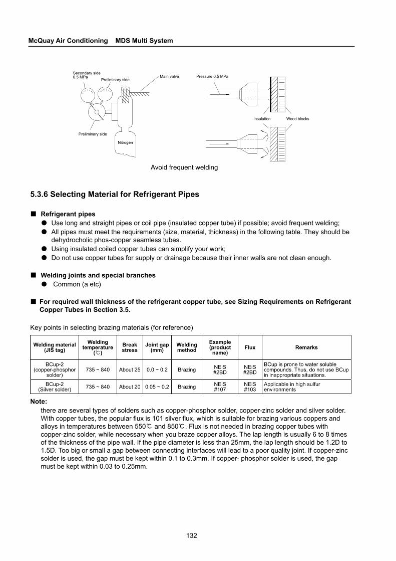
132
McQuay Air Conditioning MDS Multi System
Secondary side 0.5 MPa
Preliminary side
Preliminary side
Nitrogen
Main valve
Insulation Wood blocks
Avoid frequent welding
Pressure 0.5 MPa
5.3.6 Selecting Material for Refrigerant Pipes
Refrigerant pipes● Use long and straight pipes or coil pipe (insulated copper tube) if possible; avoid frequent welding;● All pipes must meet the requirements (size, material, thickness) in the following table. They should be
dehydrocholic phos-copper seamless tubes.● Using insulated coiled copper tubes can simplify your work;● Do not use copper tubes for supply or drainage because their inner walls are not clean enough.
Welding joints and special branches● Common (a etc)
For required wall thickness of the refrigerant copper tube, see Sizing Requirements on Refrigerant Copper Tubes in Section 3.5.
Key points in selecting brazing materials (for reference)
■
■
■
Welding material (JIS tag)
Welding temperature
(℃)Break stress
Joint gap (mm)
Welding method
Example(product name)
Flux Remarks
BCup-2(copper-phosphor
solder)735 ~ 840 About 25 0.0 ~ 0.2 Brazing NEiS
#2BDNEiS#2BD
BCup is prone to water soluble compounds. Thus, do not use BCup in inappropriate situations.
BCup-2(Silver solder) 735 ~ 840 About 20 0.05 ~ 0.2 Brazing NEiS
#107NEiS#103
Applicable in high sulfur environments
Note: there are several types of solders such as copper-phosphor solder, copper-zinc solder and silver solder. With copper tubes, the popular flux is 101 silver flux, which is suitable for brazing various coppers and alloys in temperatures between 550℃ and 850℃. Flux is not needed in brazing copper tubes with copper-zinc solder, while necessary when you braze copper alloys. The lap length is usually 6 to 8 times of the thickness of the pipe wall. If the pipe diameter is less than 25mm, the lap length should be 1.2D to 1.5D. Too big or small a gap between connecting interfaces will lead to a poor quality joint. If copper-zinc solder is used, the gap must be kept within 0.1 to 0.3mm. If copper- phosphor solder is used, the gap must be kept within 0.03 to 0.25mm.

133
CHAPTER 5Installation
Increase pressure Check whether the pressure drops
Find out the leaking point and repair it
Yes
NoSatisfactoryRefrigerant piping finished
Flow chart
The 3rd phase: satisfactory
The 2nd phase
The 1st phase
Pressure does not change after 24 hours
0.3 MPa×3 minutes
1.5 MPa×3 minutes Satisfactory
SatisfactoryPre
ssur
e
24 hours
3 m
inut
es3
min
utes
5.3.7 Air-tightness Test Order
Key points (for MDS R22 series units)Follow the order below to do the test●With each refrigerant system, test the air pipe and liquid pipe respectively by increasing pressure in
them gradually (use nitrogen)◆ Stage 1, exert a pressure of 0.3 MPa for 3 minutes → Big leaking points are likely to be found;◆ Stage 2, exert a pressure of 1.5 MPa for 3 minutes → Big leaking points are likely to be found;◆ Stage 3, exert a pressure of 2.8 MPa for 24 hours.
Note: Even with a pressure of 2.8 MPa, tiny leaking points are hard to be found if the time is short. Therefore, in stage 3 you are required to wait for 24 hours before observation.
The pressure must not exceed 2.8 MPa!
●Check if the pressure drops◆ If the pressure does not drop, the pipes are good.◆ If the pressure drops, you should find the leaking point(s) by following the description in 4.3.8.◆ If the temperature when you exerted pressure is different from that when you took observation,
you should modify your result. A difference of one Celsius degree causes a pressure variance of 0.01 MPa.
◆ Modified value = (temperature when exerting pressure - temperature when observing) x 0.1;
For example, if the pressure is 2.8 MPa and the temperature is 25℃ when you exert pressure, and the pressure is 2.75 MPa and the temperature is 20℃ when you observe, the pipe is still air-tight.
■
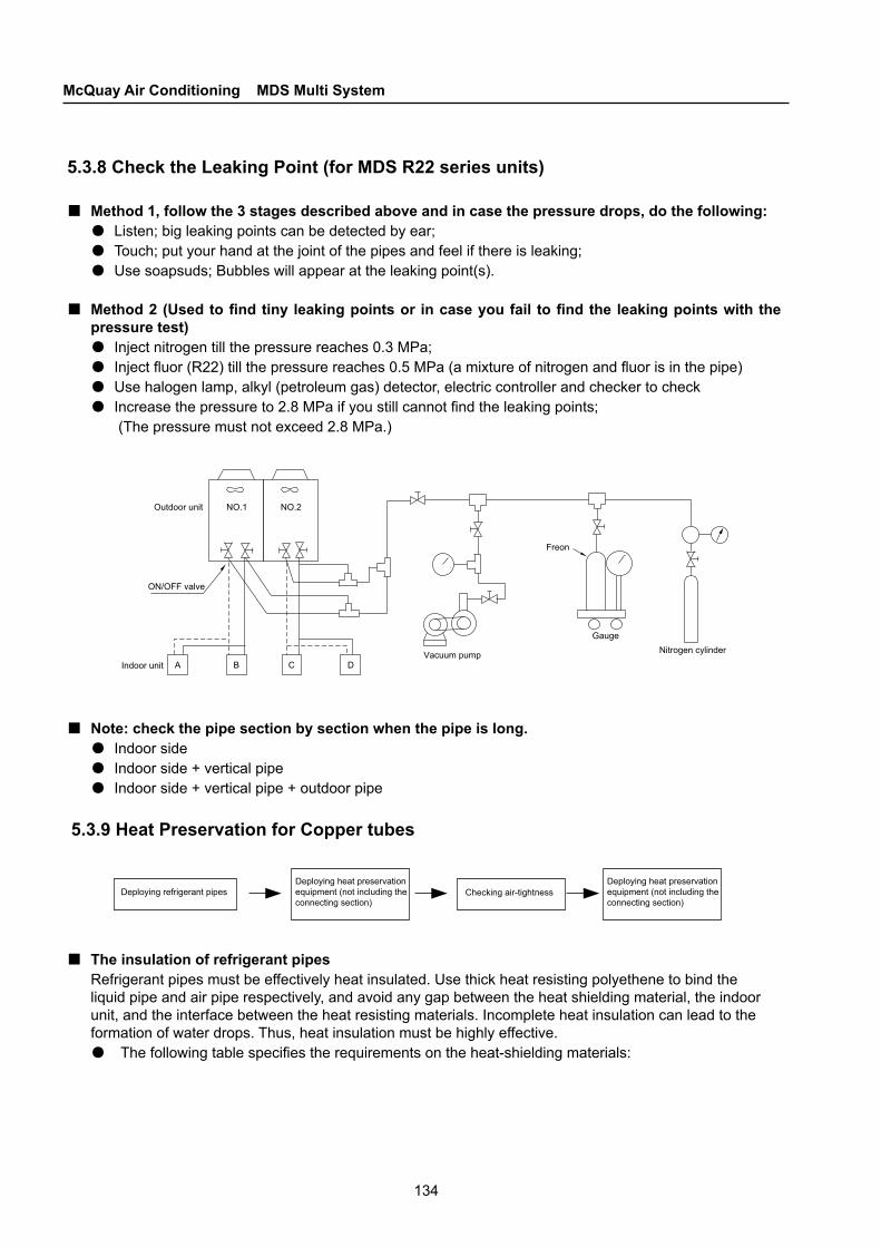
134
McQuay Air Conditioning MDS Multi System
Outdoor unit NO.1
A B C D
NO.2
Vacuum pump
Freon
GaugeNitrogen cylinder
ON/OFF valve
Indoor unit
Deploying refrigerant pipesDeploying heat preservation equipment (not including the connecting section)
Deploying heat preservation equipment (not including the connecting section)
Checking air-tightness
5.3.8 Check the Leaking Point (for MDS R22 series units)
Method 1, follow the 3 stages described above and in case the pressure drops, do the following:●Listen; big leaking points can be detected by ear; ●Touch; put your hand at the joint of the pipes and feel if there is leaking; ●Use soapsuds; Bubbles will appear at the leaking point(s).
Method 2 (Used to find tiny leaking points or in case you fail to find the leaking points with the pressure test)● Inject nitrogen till the pressure reaches 0.3 MPa;● Inject fluor (R22) till the pressure reaches 0.5 MPa (a mixture of nitrogen and fluor is in the pipe)●Use halogen lamp, alkyl (petroleum gas) detector, electric controller and checker to check● Increase the pressure to 2.8 MPa if you still cannot find the leaking points;
(The pressure must not exceed 2.8 MPa.)
■
■
Note: check the pipe section by section when the pipe is long.● Indoor side● Indoor side + vertical pipe● Indoor side + vertical pipe + outdoor pipe
5.3.9 Heat Preservation for Copper tubes
■
The insulation of refrigerant pipes Refrigerant pipes must be effectively heat insulated. Use thick heat resisting polyethene to bind the liquid pipe and air pipe respectively, and avoid any gap between the heat shielding material, the indoor unit, and the interface between the heat resisting materials. Incomplete heat insulation can lead to the formation of water drops. Thus, heat insulation must be highly effective.● The following table specifies the requirements on the heat-shielding materials:
■
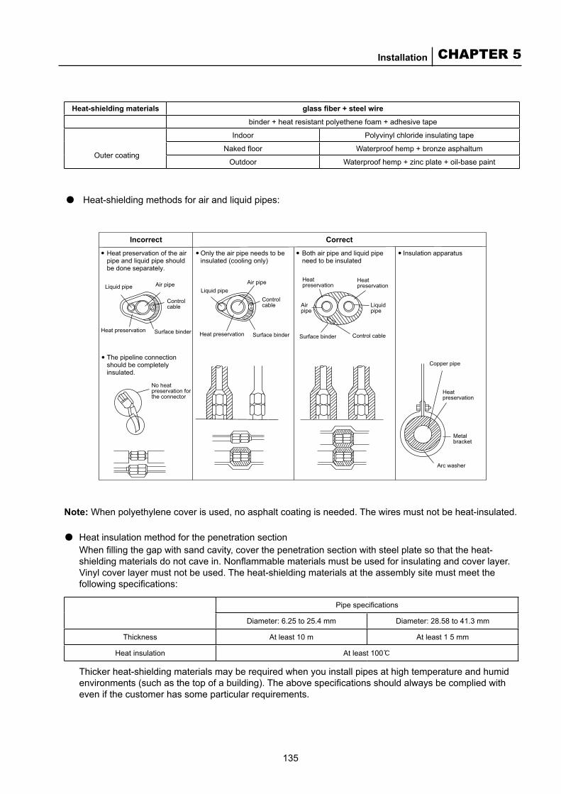
135
CHAPTER 5Installation
Liquid pipe
Incorrect Correct
Liquid pipeAir pipe Air pipe Heat
preservation
Surface binder Surface binder
Control cable
Control cable
Heat preservationHeat preservation
Liquid pipe
Air pipe
Heat preservation
Surface binder Control cable
Copper pipe
No heat preservation for the connector
Heat preservation
Metal bracket
Arc washer
Heat preservation of the air pipe and liquid pipe should be done separately.
The pipeline connection should be completely insulated.
Only the air pipe needs to be insulated (cooling only)
Both air pipe and liquid pipe need to be insulated
Insulation apparatus
Heat-shielding materials glass fiber + steel wire
binder + heat resistant polyethene foam + adhesive tape
Indoor Polyvinyl chloride insulating tape
Outer coatingNaked floor Waterproof hemp + bronze asphaltum
Outdoor Waterproof hemp + zinc plate + oil-base paint
● Heat-shielding methods for air and liquid pipes:
Note: When polyethylene cover is used, no asphalt coating is needed. The wires must not be heat-insulated.
●Heat insulation method for the penetration sectionWhen filling the gap with sand cavity, cover the penetration section with steel plate so that the heat-shielding materials do not cave in. Nonflammable materials must be used for insulating and cover layer. Vinyl cover layer must not be used. The heat-shielding materials at the assembly site must meet the following specifications:
Pipe specifications
Diameter: 6.25 to 25.4 mm Diameter: 28.58 to 41.3 mm
Thickness At least 10 m At least 1 5 mm
Heat insulation At least 100℃
Thicker heat-shielding materials may be required when you install pipes at high temperature and humid environments (such as the top of a building). The above specifications should always be complied with even if the customer has some particular requirements.
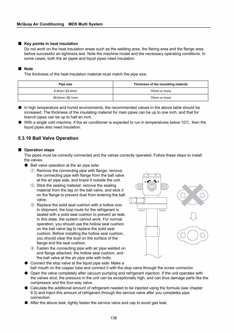
136
McQuay Air Conditioning MDS Multi System
o s
Key points in heat insulationDo not work on the heat insulation areas such as the welding area, the flaring area and the flange area before successful air-tightness test. Note the machine model and the necessary operating conditions. In some cases, both the air pipes and liquid pipes need insulation.
NoteThe thickness of the heat insulation material must match the pipe size.
■
■
Pipe size Thickness of the insulating material
6.4mm~25.4mm 10mm or more
28.6mm~38.1mm 15mm or more
● In high temperature and humid environments, the recommended values in the above table should be increased. The thickness of the insulating material for main pipes can be up to one inch, and that for branch pipes can be up to half an inch.
●With a single cold machine, if the air conditioner is expected to run in temperatures below 10℃, then the liquid pipes also need insulation.
5.3.10 Ball Valve Operation
Operation stepsThe pipes must be correctly connected and the valves correctly operated. Follow these steps to install the valves.●Ball valve operation at the air pipe side:
① Remove the connecting pipe with flange: remove the connecting pipe with flange from the ball valve at the air pipe side, and braze it outside the unit.
② Stick the sealing material: remove the sealing material from the tag on the ball valve, and stick it on the flange to prevent dust from entering the ball valve.
③ Replace the solid seal cushion with a hollow one: In shipment, the loop route for the refrigerant is sealed with a solid seal cushion to prevent air leak. In this state, the system cannot work. For normal operation, you should use the hollow seal cushion on the ball valve tag to replace the solid seal cushion. Before installing the hollow seal cushion, you should clear the dust on the surface of the flange and the seal cushion.
④ Fasten the connecting pipe with air pipe welded on and flange attached, the hollow seal cushion, and the ball valve at the air pipe side with bolts.
●Connect the stop valve at the liquid pipe side: Make a bell mouth on the copper tube and connect it with the stop valve through the screw connector.
●Open the valve completely after vacuum pumping and refrigerant injection. If the unit operates with the valves shut, the pressure in the unit can be exceptionally high, and can thus damage parts like the compressor and the four-way valve.
●Calculate the additional amount of refrigerant needed to be injected using the formula (see chapter 9.3) and inject this amount of refrigerant through the service valve after you completes pipe connection.
●After the above task, tightly fasten the service valve and cap to avoid gas leak.
■
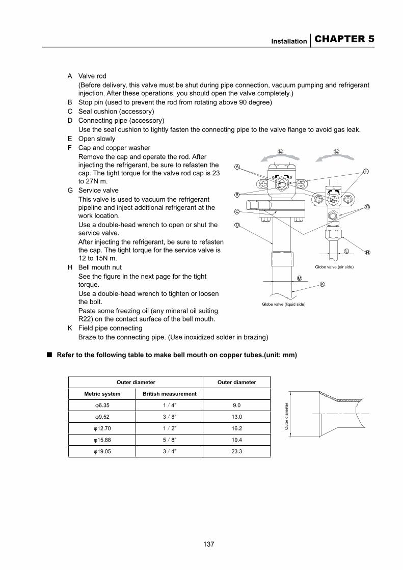
137
CHAPTER 5Installation
Globe valve (liquid side)
Globe valve (air side)
Out
er d
iam
eter
A Valve rod(Before delivery, this valve must be shut during pipe connection, vacuum pumping and refrigerant injection. After these operations, you should open the valve completely.)
B Stop pin (used to prevent the rod from rotating above 90 degree) C Seal cushion (accessory)D Connecting pipe (accessory)
Use the seal cushion to tightly fasten the connecting pipe to the valve flange to avoid gas leak.E Open slowlyF Cap and copper washer
Remove the cap and operate the rod. After injecting the refrigerant, be sure to refasten the cap. The tight torque for the valve rod cap is 23 to 27N m.
G Service valveThis valve is used to vacuum the refrigerant pipeline and inject additional refrigerant at the work location. Use a double-head wrench to open or shut the service valve. After injecting the refrigerant, be sure to refasten the cap. The tight torque for the service valve is 12 to 15N m.
H Bell mouth nutSee the figure in the next page for the tight torque. Use a double-head wrench to tighten or loosen the bolt. Paste some freezing oil (any mineral oil suiting R22) on the contact surface of the bell mouth.
K Field pipe connectingBraze to the connecting pipe. (Use inoxidized solder in brazing)
Refer to the following table to make bell mouth on copper tubes.(unit: mm)■
Outer diameter Outer diameter
Metric system British measurement
φ6.35 1/4” 9.0
φ9.52 3/8” 13.0
φ12.70 1/2” 16.2
φ15.88 5/8” 19.4
φ19.05 3/4” 23.3
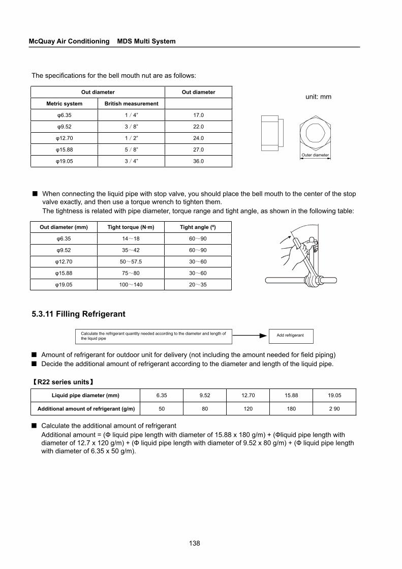
138
McQuay Air Conditioning MDS Multi System
Calculate the refrigerant quantity needed according to the diameter and length of the liquid pipe
Add refrigerant
The specifications for the bell mouth nut are as follows:
Out diameter Out diameter
Metric system British measurement
φ6.35 1/4” 17.0
φ9.52 3/8” 22.0
φ12.70 1/2” 24.0
φ15.88 5/8” 27.0
φ19.05 3/4” 36.0Outer diameter
unit: mm
■When connecting the liquid pipe with stop valve, you should place the bell mouth to the center of the stop valve exactly, and then use a torque wrench to tighten them. The tightness is related with pipe diameter, torque range and tight angle, as shown in the following table:
Out diameter (mm) Tight torque (N·m) Tight angle (º)
φ6.35 14~18 60~90
φ9.52 35~42 60~90
φ12.70 50~57.5 30~60
φ15.88 75~80 30~60
φ19.05 100~140 20~35
5.3.11 Filling Refrigerant
Liquid pipe diameter (mm) 6.35 9.52 12.70 15.88 19.05
Additional amount of refrigerant (g/m) 50 80 120 180 2 90
■Amount of refrigerant for outdoor unit for delivery (not including the amount needed for field piping)■Decide the additional amount of refrigerant according to the diameter and length of the liquid pipe.
【R22 series units】
■Calculate the additional amount of refrigerantAdditional amount = (Ф liquid pipe length with diameter of 15.88 x 180 g/m) + (Фliquid pipe length with diameter of 12.7 x 120 g/m) + (Ф liquid pipe length with diameter of 9.52 x 80 g/m) + (Ф liquid pipe length with diameter of 6.35 x 50 g/m).
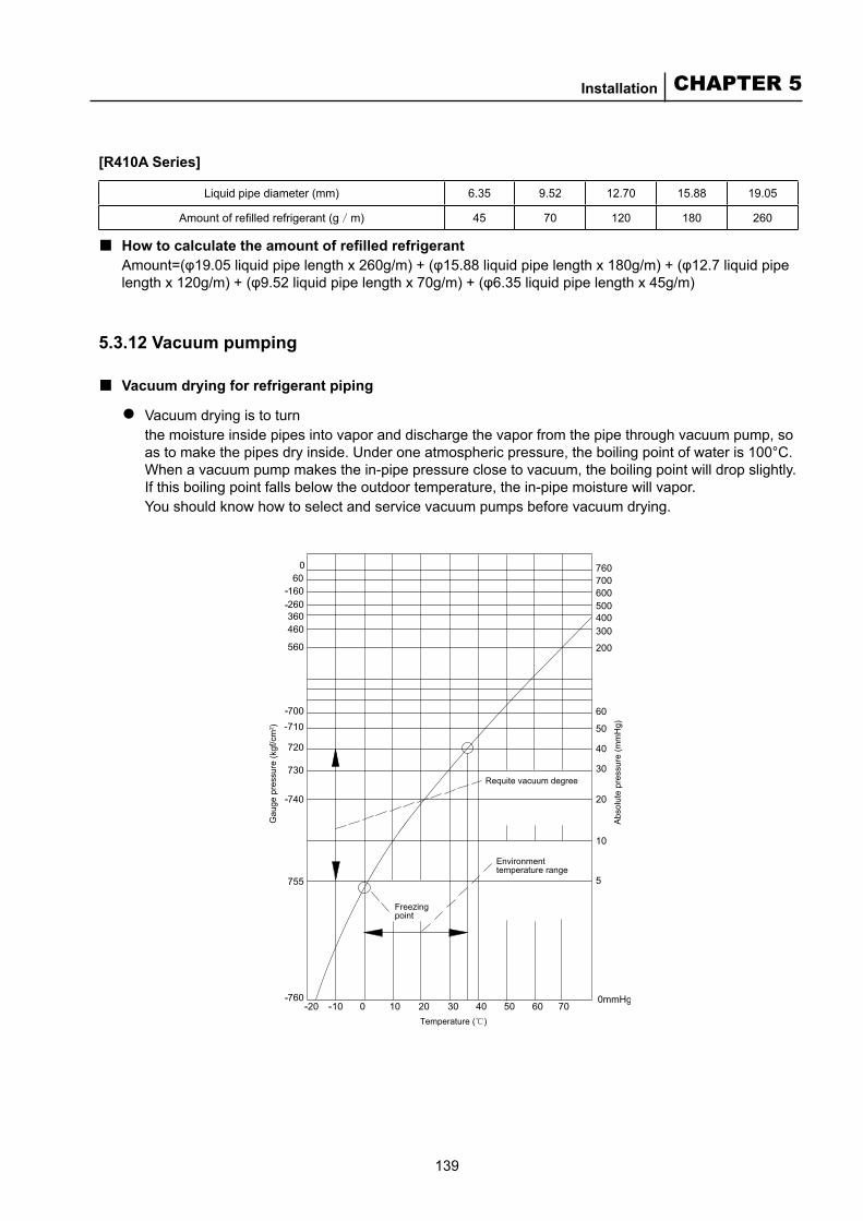
139
CHAPTER 5Installation
Requite vacuum degree
Environment temperature range
Freezing point
Gau
ge p
ress
ure
(kgf
/cm
2 )
Abs
olut
e pr
essu
re (m
mH
g)
Temperature ( )
[R410A Series]
Liquid pipe diameter (mm) 6.35 9.52 12.70 15.88 19.05
Amount of refilled refrigerant (g/m) 45 70 120 180 260
How to calculate the amount of refilled refrigerantAmount=(φ19.05 liquid pipe length x 260g/m) + (φ15.88 liquid pipe length x 180g/m) + (φ12.7 liquid pipe length x 120g/m) + (φ9.52 liquid pipe length x 70g/m) + (φ6.35 liquid pipe length x 45g/m)
5.3.12 Vacuum pumping
Vacuum drying for refrigerant piping
Vacuum drying is to turn the moisture inside pipes into vapor and discharge the vapor from the pipe through vacuum pump, so as to make the pipes dry inside. Under one atmospheric pressure, the boiling point of water is 100°C. When a vacuum pump makes the in-pipe pressure close to vacuum, the boiling point will drop slightly. If this boiling point falls below the outdoor temperature, the in-pipe moisture will vapor.You should know how to select and service vacuum pumps before vacuum drying.
■
■●
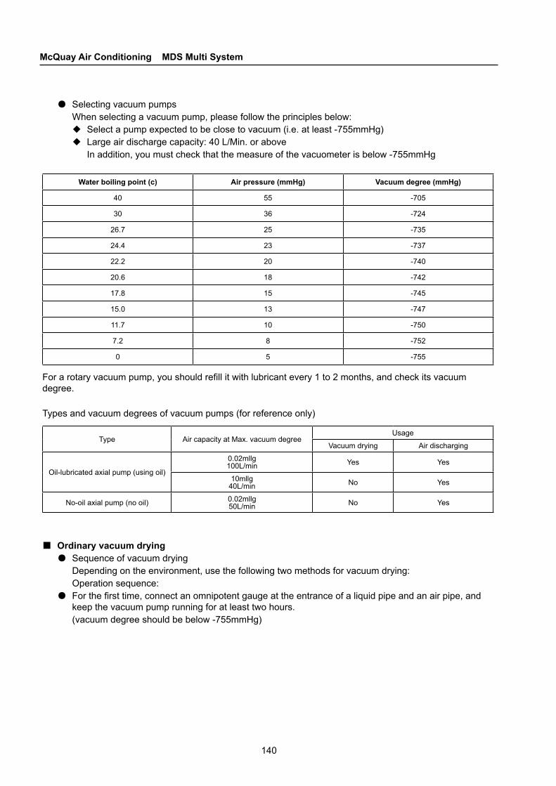
140
McQuay Air Conditioning MDS Multi System
●Selecting vacuum pumpsWhen selecting a vacuum pump, please follow the principles below:◆Select a pump expected to be close to vacuum (i.e. at least -755mmHg)◆Large air discharge capacity: 40 L/Min. or above
In addition, you must check that the measure of the vacuometer is below -755mmHg
Water boiling point (c) Air pressure (mmHg) Vacuum degree (mmHg)
40 55 -705
30 36 -724
26.7 25 -735
24.4 23 -737
22.2 20 -740
20.6 18 -742
17.8 15 -745
15.0 13 -747
11.7 10 -750
7.2 8 -752
0 5 -755
For a rotary vacuum pump, you should refill it with lubricant every 1 to 2 months, and check its vacuum degree.
Types and vacuum degrees of vacuum pumps (for reference only)
Ordinary vacuum drying●Sequence of vacuum drying
Depending on the environment, use the following two methods for vacuum drying:Operation sequence:
●For the first time, connect an omnipotent gauge at the entrance of a liquid pipe and an air pipe, and keep the vacuum pump running for at least two hours.(vacuum degree should be below -755mmHg)
■
Type Air capacity at Max. vacuum degreeUsage
Vacuum drying Air discharging
Oil-lubricated axial pump (using oil)
0.02mllg100L/min Yes Yes
10mllg40L/min No Yes
No-oil axial pump (no oil) 0.02mllg50L/min No Yes
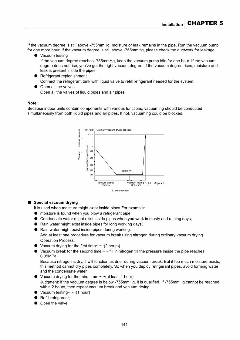
141
CHAPTER 5Installation
Ordinary vacuum drying processKgf / cm2
Vacuum drying2 hours
Vacuum testing2 hours
Add refrigerant
3 hours needed
(Atm
osph
eric
pre
ssur
e)
Vac
uum
In
crea
se p
ress
ure
-755mmHg
If the vacuum degree is still above -755mmHg, moisture or leak remains in the pipe. Run the vacuum pump for one more hour. If the vacuum degree is still above -755mmHg, please check the ductwork for leakage.
●Vacuum testingIf the vacuum degree reaches -755mmHg, keep the vacuum pump idle for one hour. If the vacuum degree does not rise, you’ve got the right vacuum degree. If the vacuum degree rises, moisture and leak is present inside the pipes.
●Refrigerant replenishmentConnect the refrigerant tank with liquid valve to refill refrigerant needed for the system.
●Open all the valvesOpen all the valves of liquid pipes and air pipes.
Note:Because indoor units contain components with various functions, vacuuming should be conducted simultaneously from both liquid pipes and air pipes. If not, vacuuming could be blocked.
Special vacuum dryingIt is used when moisture might exist inside pipes.For example:●moisture is found when you blow a refrigerant pipe;●Condensate water might exist inside pipes when you work in musty and raining days;●Rain water might exist inside pipes for long working days;●Rain water might exist inside pipes during working.
Add at least one procedure for vacuum break using nitrogen during ordinary vacuum dryingOperation Process:
●Vacuum drying for the first time……(2 hours)●Vacuum break for the second time……fill in nitrogen till the pressure inside the pipe reaches
0.05MPa;Because nitrogen is dry, it will function as drier during vacuum break. But if too much moisture exists, this method cannot dry pipes completely. So when you deploy refrigerant pipes, avoid forming water and the condensate water.
●Vacuum drying for the third time……(at least 1 hour) Judgment: if the vacuum degree is below -755mmHg, it is qualified. If -755mmHg cannot be reached within 2 hours, then repeat vacuum break and vacuum drying;
●Vacuum testing……(1 hour)●Refill refrigerant;●Open the valve.
■
142
McQuay Air Conditioning MDS Multi System
Special vacuum drying processKgf / cm2
(Atm
osph
eric
pre
ssur
e)
Vac
uum
In
crea
se p
ress
ure
Vac
uum
dry
ing
(2 h
ours
)
Vac
uum
bre
ach
Vac
uum
dry
ing
(1 h
our)
Vac
uum
test
ing
(1 h
our)
Add
refri
gera
nt
NoteNitrogen must be used for vacuum break.Using hydrogen might cause blast.Special vacuum drying flow chart
5.4 R410A Pipes
5.4.1 Pipe Specifications
Fixed torque and its standard for flare nuts ■Operation valve dimension Tightening torque N • m (kg • m) Tightening angel (°) Recommended tool length (mm)
φ6.35 14-18(1.4-1.8) 45-60 150
φ9.52 34-42(3.4-4.2) 30-45 200
φ12.70 49-61(4.9-6.1) 30-45 250
φ15.88 68-82(6.8-8.2) 15-20 300
Note: After fastening a nut, select a spanner with recommended length to fix according to the angle illustrated in the table.
Fixed torqueUse spanner to fix the flare connection well. For a nut toque, please fix according to lower limit of the fixed torque values in the table.
Flare manufacturingThe flare size for R410A is different from that for R22. Flare tool for R410A is recommended. But if you adjust the extrusion length of a cooper pipe for B inches, you can use the original tool.
■
■
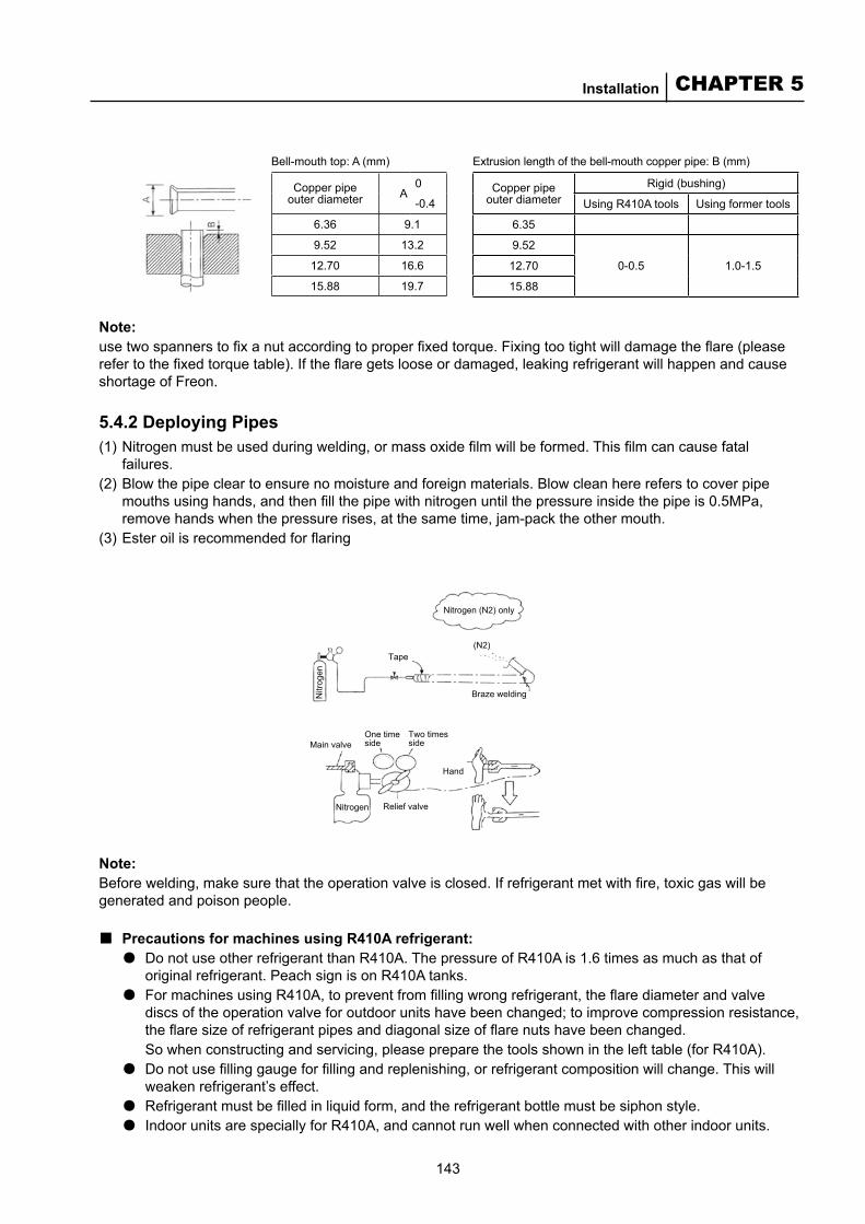
143
CHAPTER 5Installation
Nitrogen (N2) only
(N2)
Braze welding
Main valve
Nitrogen Relief valve
One time side
Two times side
Hand
Tape
Nitr
ogen
Note: use two spanners to fix a nut according to proper fixed torque. Fixing too tight will damage the flare (please refer to the fixed torque table). If the flare gets loose or damaged, leaking refrigerant will happen and cause shortage of Freon.
5.4.2 Deploying Pipes (1) Nitrogen must be used during welding, or mass oxide film will be formed. This film can cause fatal
failures.(2) Blow the pipe clear to ensure no moisture and foreign materials. Blow clean here refers to cover pipe
mouths using hands, and then fill the pipe with nitrogen until the pressure inside the pipe is 0.5MPa, remove hands when the pressure rises, at the same time, jam-pack the other mouth.
(3) Ester oil is recommended for flaring
Note: Before welding, make sure that the operation valve is closed. If refrigerant met with fire, toxic gas will be generated and poison people.
Precautions for machines using R410A refrigerant:●Do not use other refrigerant than R410A. The pressure of R410A is 1.6 times as much as that of
original refrigerant. Peach sign is on R410A tanks.●For machines using R410A, to prevent from filling wrong refrigerant, the flare diameter and valve
discs of the operation valve for outdoor units have been changed; to improve compression resistance, the flare size of refrigerant pipes and diagonal size of flare nuts have been changed.So when constructing and servicing, please prepare the tools shown in the left table (for R410A).
●Do not use filling gauge for filling and replenishing, or refrigerant composition will change. This will weaken refrigerant’s effect.
●Refrigerant must be filled in liquid form, and the refrigerant bottle must be siphon style.● Indoor units are specially for R410A, and cannot run well when connected with other indoor units.
■
Bell-mouth top: A (mm)
Copper pipe outer diameter A
0
-0.4
6.36 9.1
9.52 13.2
12.70 16.6
15.88 19.7
Extrusion length of the bell-mouth copper pipe: B (mm)
Copper pipe outer diameter
Rigid (bushing)
Using R410A tools Using former tools
6.35
9.52
0-0.5 1.0-1.512.70
15.88
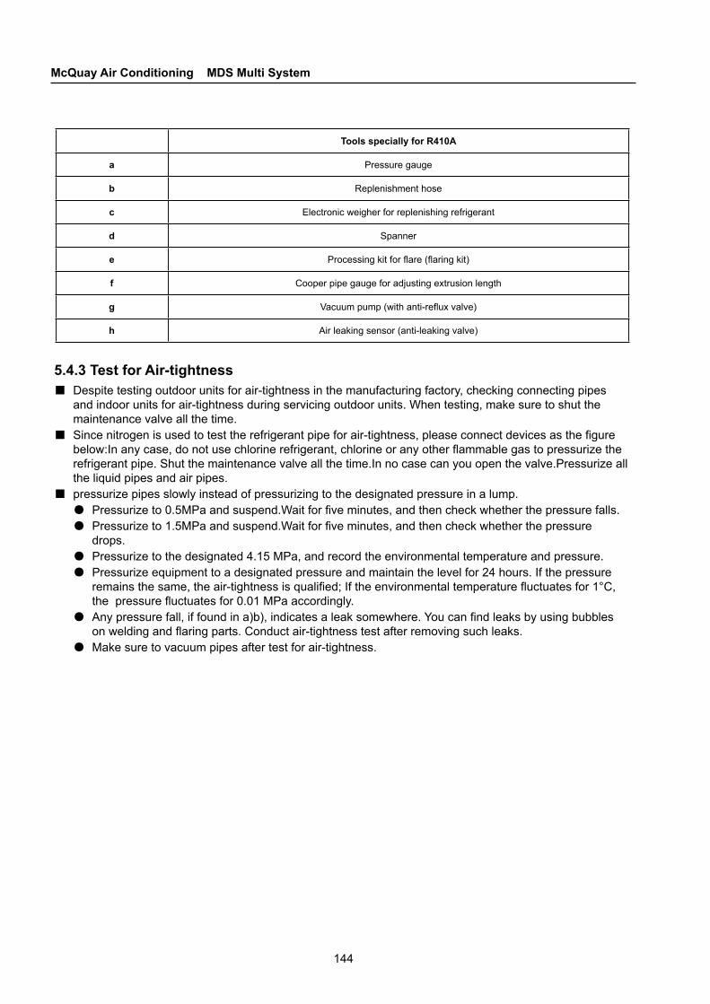
144
McQuay Air Conditioning MDS Multi System
Tools specially for R410A
a Pressure gauge
b Replenishment hose
c Electronic weigher for replenishing refrigerant
d Spanner
e Processing kit for flare (flaring kit)
f Cooper pipe gauge for adjusting extrusion length
g Vacuum pump (with anti-reflux valve)
h Air leaking sensor (anti-leaking valve)
5.4.3 Test for Air-tightness■Despite testing outdoor units for air-tightness in the manufacturing factory, checking connecting pipes
and indoor units for air-tightness during servicing outdoor units. When testing, make sure to shut the maintenance valve all the time.
■Since nitrogen is used to test the refrigerant pipe for air-tightness, please connect devices as the figure below:In any case, do not use chlorine refrigerant, chlorine or any other flammable gas to pressurize the refrigerant pipe. Shut the maintenance valve all the time.In no case can you open the valve.Pressurize all the liquid pipes and air pipes.
■pressurize pipes slowly instead of pressurizing to the designated pressure in a lump.●Pressurize to 0.5MPa and suspend.Wait for five minutes, and then check whether the pressure falls.●Pressurize to 1.5MPa and suspend.Wait for five minutes, and then check whether the pressure
drops.●Pressurize to the designated 4.15 MPa, and record the environmental temperature and pressure.●Pressurize equipment to a designated pressure and maintain the level for 24 hours. If the pressure
remains the same, the air-tightness is qualified; If the environmental temperature fluctuates for 1°C, the pressure fluctuates for 0.01 MPa accordingly.
●Any pressure fall, if found in a)b), indicates a leak somewhere. You can find leaks by using bubbles on welding and flaring parts. Conduct air-tightness test after removing such leaks.
●Make sure to vacuum pipes after test for air-tightness.

145
CHAPTER 5Installation
In addition to the above considerations specific to R410A and compatible units, you
also need to pay attention to the following:Using anti-reflux commutator to prevent machine oil of the vacuum pump from entering the refrigerant system.
(Outdoor unit)
Air side maintenance valveLiquid side maintenance valve
Anti-return connector
ClosedOpen
Connecting pipe of the pressure gauge
Open
<Vacuum pump>
Indoor unit
Indoor unit
Air side maintenance valve
Anti-return connector
Indoor unit
(Outdoor unit)
Indoor unit Indoor unit
Indoor unit
Closed
Clo
sed
Air-tightness test completed
Begin vacuumizing
Begin vacuumizing
Check the vacuometer
Add refrigerant
If the pressure gauge indicates 1KPa/cm2 or less than 755mmHg, run the vacuum pump for another hour.Check that the indication of the pressure gauge does not increase after one or more hours.
If moisture or leakage exists inside the system, the indication of the pressure gauge will increase.
5.4.4 Vacuum PumpingPlease vacuum simultaneously from the anti-return connectors of maintenance valves at liquid side and air side.
5.5 Design, Manufacturing and Fixing of Condensing pipes
5.5.1 Designing Drainpipes
Selecting the sizes of main drainpipes and risersSelect the drainpipe size from the below table according to the amount of condensate water discharged from main pipes;Based on 1HP 2L/h, the amount of condensate water for three units with 2HP and two units with 3HP is calculated as follows:2(L/h)x 2(HP)x 3(unit)+2L/h x 3(HP)x 2(unit)=24L/h.
■
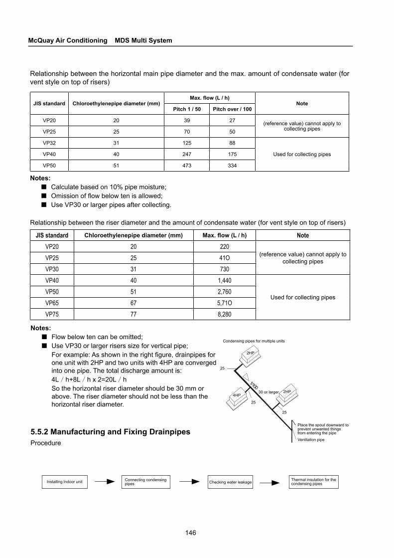
146
McQuay Air Conditioning MDS Multi System
Condensing pipes for multiple units
2HP
2HP4HP
25
30 or larger
Ventilation pipe
Place the spout downward to prevent unwanted things from entering the pipe
25
25
Checking water leakageInstalling Indoor unit Connecting condensing pipes
Thermal insulation for the condensing pipes
Relationship between the horizontal main pipe diameter and the max. amount of condensate water (for vent style on top of risers)
JIS standard Chloroethylenepipe diameter (mm)Max. flow (L / h)
NotePitch 1 / 50 Pitch over / 100
VP20 20 39 27 (reference value) cannot apply to collecting pipesVP25 25 70 50
VP32 31 125 88
Used for collecting pipesVP40 40 247 175
VP50 51 473 334
Notes:■Calculate based on 10% pipe moisture; ■Omission of flow below ten is allowed;■Use VP30 or larger pipes after collecting.
Relationship between the riser diameter and the amount of condensate water (for vent style on top of risers)
JIS standard Chloroethylenepipe diameter (mm) Max. flow (L / h) NoteVP20 20 220
(reference value) cannot apply to collecting pipesVP25 25 41O
VP30 31 730VP40 40 1,440
Used for collecting pipesVP50 51 2,760VP65 67 5,71OVP75 77 8,280
Notes:■Flow below ten can be omitted;■Use VP30 or larger risers size for vertical pipe;
For example: As shown in the right figure, drainpipes for one unit with 2HP and two units with 4HP are converged into one pipe. The total discharge amount is: 4L/h+8L/h x 2=20L/hSo the horizontal riser diameter should be 30 mm or above. The riser diameter should not be less than the horizontal riser diameter.
5.5.2 Manufacturing and Fixing DrainpipesProcedure

147
CHAPTER 5Installation
Indoor unit
Indoor unit
Indoor unit
Bulkhead
H: 50 mm or higherH
H
Bulkhead
5.5.3 Drainpipe pitches and its prop ■Fixing pitches of the drainpipe should be at least 1/100
● Make the drainpipe as short as possible and discharge water down the slope (no cavities along the slope)
Type Rated diameter Spacing
Hard PVC pipe 25 ~ 40mm less than 1.0m
■ For long drainpipes, you can use suspension bolts to assure a pitch of 1/100 (cannot bend PVC pipes)■ Prop capacity of horizontal pipes is as follows:
■ Make horizontal pipes as short as possible.
5.5.4 Traps for Condensate WaterFor indoor units which generate negative pressure at water outlets, the condensate water outlets should be equipped with traps to prevent bad smell from entering indoor units.■ Mount traps as illustrated in the right figure.■ Mount one trap for each indoor unit.Sharing one trap by several indoor units is not allowed.■ When mounting traps, leave room for future cleaning.
5.5.5 Collecting Pipes for Discharging Water of Some Indoor Units■ The typical method is to mount pipes from the upstream and make diameters of downstream
connecting pipes as large as possible.■Make pipes as short as possible and the quantity of indoor units in each group as few as possible.
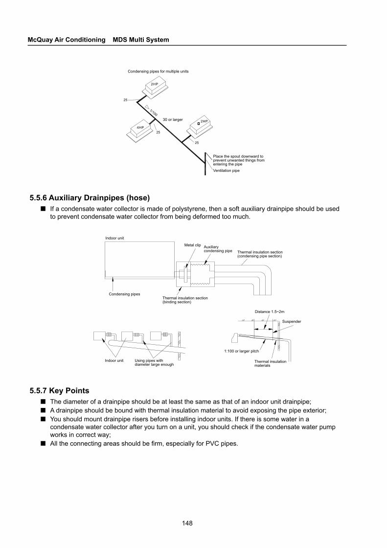
148
McQuay Air Conditioning MDS Multi System
Condensing pipes for multiple units
30 or larger
Ventilation pipe
Place the spout downward to prevent unwanted things from entering the pipe
Indoor unit
Condensing pipes
Metal clip
Thermal insulation section (binding section)
Indoor unit
Thermal insulation section (condensing pipe section)
Auxiliary condensing pipe
Distance 1.5~2m
Suspender
Using pipes with diameter large enough
1:100 or larger pitch
Thermal insulation materials
5.5.6 Auxiliary Drainpipes (hose)■ If a condensate water collector is made of polystyrene, then a soft auxiliary drainpipe should be used
to prevent condensate water collector from being deformed too much.
5.5.7 Key Points■ The diameter of a drainpipe should be at least the same as that of an indoor unit drainpipe; ■A drainpipe should be bound with thermal insulation material to avoid exposing the pipe exterior;■You should mount drainpipe risers before installing indoor units. If there is some water in a
condensate water collector after you turn on a unit, you should check if the condensate water pump works in correct way;
■All the connecting areas should be firm, especially for PVC pipes.

149
CHAPTER 5Installation
5.5.8 Precautions for discharge risers
Ceiling
Connecting pipe
200m
m
Ventilation equipment
Elastic hose
Ceiling
300m
m o
r sm
alle
r
500m
m o
r sm
alle
r
1~1.5m
Use spirit level to check if indoor units and ceiling are level; Mount ventilating devices to discharge condensate water well.
If there is a need to heighten a drainpipe, it should be below 30cm; If the height is above 50cm, leakage may happen.
Lean upwards
Ceiling
Prop
1:100 or larger pitch
1~1.5m
Ceiling
Don’t cause hoses to lean upwards after connecting ports. This tends to cause reverse water flow, and to cause water leakage when you stop a unit.
When connecting drainpipes, don’t put force on the pipes at one side of a system. Drainpipes between connecting areas and this system cannot be loose. Hooks must be used to fix drainpipes.
Ventilation outlet Drainpipe clip
1:100 or larger pitch
100mm or larger
Centralized drainpipe
If you mount centralized drainpipes, please refer to the below figure:
150
McQuay Air Conditioning MDS Multi System
6.1 User Guide
6.1.1 Responsibilities and ObligationsThis product is covered under McQuay warranty during the warranty period.Only McQuay technicians or experienced professionals designated by McQuay are allowed to install, test and servicing this series products.
6.1.2 Unpacking InspectionUpon receipt of the units, please check them against the packing list.Check carefully if the units are damaged during transportation, and if all the components are complete and in good condition.In case of any damaged unit or missing parts, please inform McQuay’s local branch or dealer in writing immediately.
6.1.3 Unit ApplicationThe total installed capacity of indoor units can be greater than but not more than 120% of the capacity of the outdoor units. However, the total capacity of the indoor units in operation should not be larger than that of the outdoor units. Otherwise, the output capacity of each indoor unit might not reach its rated value.All the indoor units are powered in a centralized manner.Before servicing and maintenance, check that the main power supply is cut off.After receiving the stop signal, the fan and electronic expansion valve of each indoor unit normally go on running for another 20 ~ 60 seconds. In this way, the indoor unit can make use of the afterheat or the cool air that remains in the heat exchanger, and also get ready for the next start. When the working mode of the indoor unit clashes with that of the outdoor unit, the indoor unit hand controller will indicate that a mode clash is in place. In this case, the indoor unit will stop working. To restart the indoor unit, you need to set it to a mode that does not clash with the current mode of the outdoor unit. The cooling mode does not clash with the dehumidification mode. The air supply mode does not clash with any other mode.The digital compressor adjusts the refrigerant flow by modulating the opening degree of the PWM solenoid. Normally, while the solenoid is operating, it clicks periodically.
6.2 Servicing and Maintenance
Caution
Do not use or store inflammable and explosive articles beside the air conditioning unit.
■
■
■
■
■
■
C H A P T E R
6 Servicing and Maintenance
151
CHAPTER 6Servicing and Maintenance
Power the indoor units in a centralized way.Check whether parts such as the bracket are damaged after longtime service.Do not alter or repair the product without authorization. To relocate the air conditioner, please contact the dealer or professional installation personnel.Do not install the air conditioner without authorization. Installation should be done by professionals to ensure that the unit works reliably for a long time.In case of any failure, please cut off the main power supply of the unit immediately.Do not remove the blade shield of an outdoor unit. Never put your hand or foreign matters inside the air outlet of the indoor and outdoor units.Do not check or repair the air conditioning unit while it is running.Do not splash water onto the unit, or operate the unit with wet hands.
6.2.1 PrecautionsBefore installation, check that the power supply meets the specifications on the nameplate and is safe to use.Before starting the unit, check that the power cables are correctly connected, to avoid electric shock or fire.Keep the air conditioning unit out of the reach of children.Cut off the main power supply before cleaning the air conditioning unit or replacing the air filtering screen.Cut off the main power supply if the air conditioning unit is to be left unused for a long time.Do not step onto the air conditioning unit or pile up anything on it.To avoid electricity shock, the unit must be properly grounded through the power supply socket which is well grounded. The earthing line must not be connected to gas pipes, water pipes, lightning rods or telephone lines. Once the air conditioner is turned on, it should operate for at least 5 minutes. Otherwise, compressor oil return might not work properly.Once the unit is installed, it should be checked for electricity leakage.
6.2.2 Servicing and Maintenance
Daily MaintenanceAll the units are strictly tested and inspected before they leave factory. To ensure the units can work reliably for a long time, users are recommended to arrange regular servicing, maintenance and repair for the units.
Servicing and maintenance for MCC and MDB indoor units
Air-filtering screenThe air filtering screen is chosen according to the local environment. It is installed at the air inlet, and can effectively filter soot, dust, farina and other impurities in the air. Before the filtering screen is blocked, it makes little sense to clean it.Cleaning intervals for the filtering screen should be decided according to the location of the unit and how much impurity exists in the environment.The filtering screen is made of washable nylon or leno. To get rid of heavy particles, you can place the screen on a hard surface and knock it gently.When necessary, you can also wash the screen in warm water using neutral detergent. Do not remount the screen until it is dry.
■■■
■
■■
■■
■
■
■■
■■■
■
■
■
■●
152
McQuay Air Conditioning MDS Multi System
Fan electromotorThis component requires very little maintenance.As the motor is lubricated and sealed before leaving the factory, no more lubrication is needed during serving and maintenance work.After the unit has worked for six months, check that the fan motor is insulated from the ground.
Heat exchangerYou can clean the surface of the heat exchanger using a dust collector and a nylon brush, or using compressed air if possible. However, if an air-filtering screen is properly installed and maintained, you do not need to clean the surface of the heat exchanger.
Fire damperCheck the damper once every three months, to see if the fuse is broken, scaling, loose or fallen off. Make sure it works properly.
DrainpipeBefore starting the unit, check that the drainpipe is unobstructed, so that condensate water can be freely discharged.As the condensate water is susceptible to bacteria, please check the water collector before or after each service season, to see if it smells unusual. If so, put some algaecide or penetrant inside the water collector to prevent bacteria and slime.
Replacing partsYou can get parts from dealers nearby. While asking for a part, you need to provide information on the unit model, factory serial number of the unit, name and quantity of the part.
For units equipped with a temperature controller, please pay attention to the following:◆ Make sure the start switch is closed.◆ Press the ON button.◆ Set the temperature according to your own specific needs.◆ The fan speed is usually preset.◆ To protect the compressor, after the unit stops running, you should wait for at least three minutes to
restart the unit. This rule does not apply to units equipped with a 3-minute relay.◆ In some cases, an air rate controller can be installed to control the air rate.
Servicing and maintenance for MCK indoor unitsAlthough the air conditioner is designed for long service life even with minimum maintenance, you should check the unit periodically to bring the best out of it.
●
●
●
●
●
●
■
Part Procedure Recommended interval
Air filtering screen (indoor unit)
1. Open the air inlet grid and take out the air filtering and refreshing screens.2. Disassemble the air filtering and refreshing screens.3. Clear the dust on the air filtering screen using a cleaner or water below 40 ℃ and
containing neutral detergent. Never wash the air refreshing screen.4. Reinstall the air filtering and refreshing screens into the air inlet grid when they are dry.
Caution: never clean the air filtering screen using petrol, dehydrant, benzene or other chemicals.
Min. once a month
Indoor unitWipe the dirt and dust off the grid and panel with a piece of soft cloth soaked in war or cool water, or water containing neutral washing powder.Caution: never clean the air filtering screen using petrol, dehydrant, benzene or any volatile chemicals, as they may deform the plastic surface.
Min. once a month
Condensate water collector and pipe
1. Check that they are clean. Wash them if necessary.2. Check that the condensate water can be freely discharged.
Once every three months
Indoor fan Check that no abnormal noise is generated. When necessary
Coil of Indoor and outdoor units
1. Check and clear the dirt between the blades.2. Check and clear any foreign matter that blocks the air flow between the indoor and
outdoor units.Once a month

153
CHAPTER 6Servicing and Maintenance
Note: maintenance work immediately before the service season is listed below:Thoroughly check and clean the indoor and outdoor units.Clean or replace the air filtering screen.Clean the drainpipe.Clean the coil of the indoor and outdoor units.Check the fan for dynamic balance before starting the unit.Secure all electric connections.Check if the refrigerant leaks.
Maintenance and servicing for outdoor unitsNormally, for an air-cooled duct unit manufactured by McQuay, you only need to check and clean the heat exchanger on a quarterly basis. However, if the unit works in an oily, salty, wet or dirty environment for a long period of time, maintenance work should be done by maintenance technicians. Otherwise, both the performance and life-span of the unit might be degraded.
Compressor maintenanceAfter leaving the unit unused for a long period of time, please electrify the unit 24 hours before turning it on. In this period of time, the crankcase and heater of the outdoor unit compressor will heat up. Then it will be safer to start the compressor.
Heat exchanger maintenanceCheck the heat exchanger once before and after the service season. If there is any tilted blade, put it upright. If there is any dust or foreign matters on the surface of the heat exchanger, get rid of it using a cleaner and a nylon brush. You can also blow the dust off the surface of the heat exchanger with compressed air if possible.If the unit works in an oily, salty, wet or dirty environment for a long period of time, you should clean the heat exchanger using a special detergent. It is not advised to wash the heat exchanger with water.If lots of dust is gathered, you can clean the heat exchanger using a special detergent such as SF-98 or YD-402.
Pay attention to the following when the unit is running:◆ WhiWhile testing for air-tightness and leakage, never let combustible air such as oxygen and
acetylene get into the refrigerant loop. For safety concerns, you are strongly recommended to use nitrogen or refrigerant while doing such tests.
◆ Maintenance before and after the service season
Before the service season
Check that no obstacles exist at the air inlet or outlet.◆ Check that the grounding equipment is in good condition; otherwise it is unsafe to run the unit.
●●●●●●●
■
●
●
●
■●
Part Procedure Recommended interval
Power supply 1. Check the operating current and voltage of the indoor and outdoor units.2. Check whether the electric lines are securely connected.
Once every two monthsOnce a year
Compressor Check the weld junctions and joints of the refrigerant pipes to see if they are airtight. Once every six months
Compressor lubricant
The lubricant is filled by the manufacturer. If the refrigerant loop is airtight, there is no need to refill the lubricant.
No need for maintenance
Fan motor lubricant
All motors are properly lubricated and sealed before they leave the factory. No need for maintenance
154
McQuay Air Conditioning MDS Multi System
◆ Thoroughly check and clean the indoor and outdoor units.Clean or replace the air filtering screen.Clean the drainpipe.Clean the coil of the indoor and outdoor units.Check the fan for dynamic balance before starting the unit.Secure all electric connections.Check if the refrigerant leaks.Ask technicians to overhaul the unit and clean the filtering screen.
After the service season◆ When the weather is clear, have the air conditioner running in air supply mode for half a day to dry
its inside.◆ Turn off the power supply; otherwise the unit still consumes energy.◆ Ask technicians to overhaul the unit and clean the filtering screen.
Considerations for daily operation, maintenance and servicingSet a proper indoor temperature, preferably within the range of 26℃ ~ 28℃ for cooling and 18℃ ~ 23℃ for heating.Keep the doors and windows of air conditioned rooms closed; otherwise the air conditioner will be less effective.Windows should have a curtain or a shutter to keep out direct sunshine.Do not put floc or any other thing near the air inlet and outlet. Otherwise, the unit will be less effective or even fail.Mechanical abrasion and dust inside the unit might degrade the performance of the unit. You need to clean up and service the unit whenever necessary.Turn off the power supply while leaving the unit unused for a long period of time. To protect the air conditioner in this case, you need to turn on the power supply at least 24 hours before starting the air conditioner again, to warm up the compressor and the heater.
CautionIn case of any exception, such as burning smell, turn off the power supply immediately and seek help from the local branch or dealer.Continue using the unit in case of any exception might damage the unit or even incur a fire or electric shock.Only service technicians are allowed to service the unit. Before touching any wired equipment, check that the power supply is turned off.Before cleaning the air conditioner, check that the unit has stop running and that the power supply is turned off. Otherwise you might be injured or get an electric shock.
●
■●
●
●●
●
●
■●
●
●
●
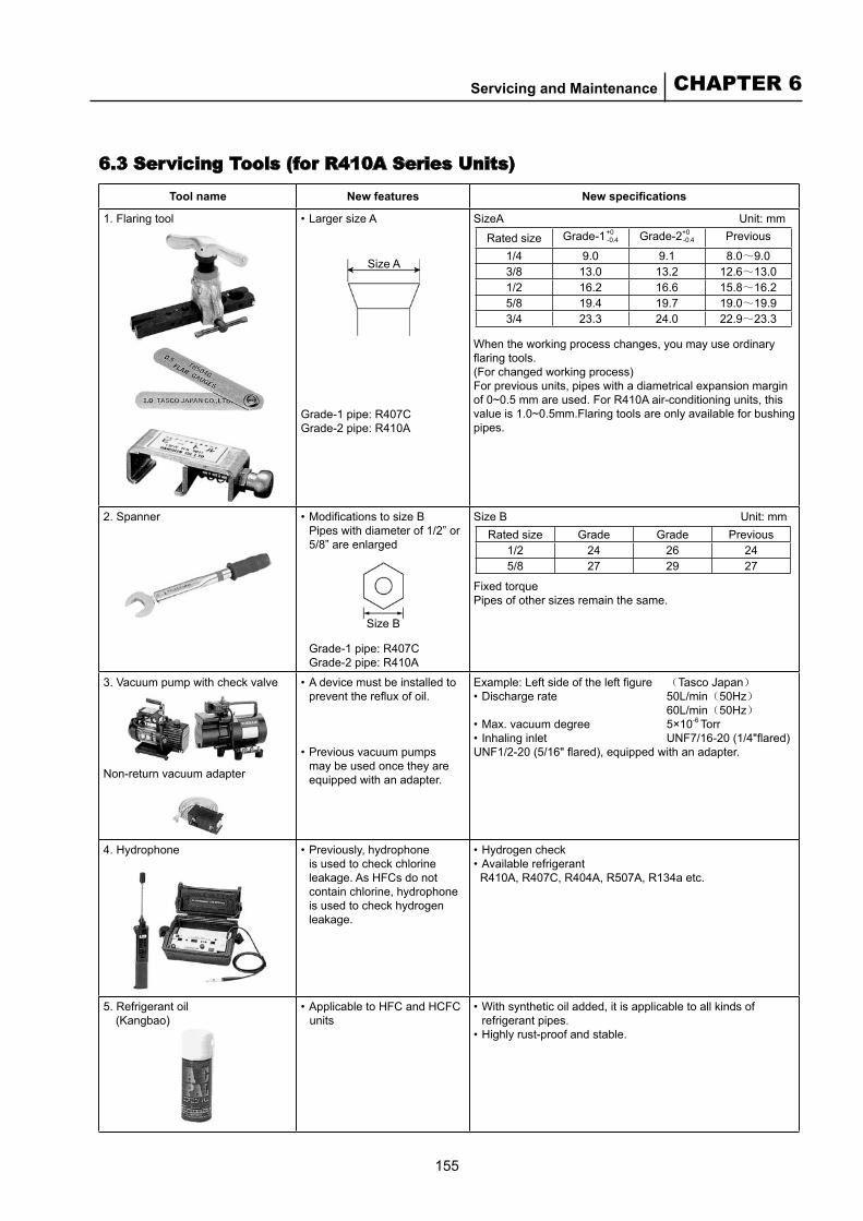
155
CHAPTER 6Servicing and Maintenance
Tool name New features New specifications
1. Flaring tool Larger size A
Size A
Grade-1 pipe: R407CGrade-2 pipe: R410A
• SizeA Unit: mm
When the working process changes, you may use ordinary flaring tools.(For changed working process)For previous units, pipes with a diametrical expansion margin of 0~0.5 mm are used. For R410A air-conditioning units, this value is 1.0~0.5mm.Flaring tools are only available for bushing pipes.
2. Spanner Modifications to size BPipes with diameter of 1/2” or 5/8” are enlarged
Size B
Grade-1 pipe: R407CGrade-2 pipe: R410A
• Size B Unit: mm
Fixed torquePipes of other sizes remain the same.
3. Vacuum pump with check valve
Non-return vacuum adapter
A device must be installed to prevent the reflux of oil.
Previous vacuum pumps may be used once they are equipped with an adapter.
•
•
Example: Left side of the left figure (Tasco Japan)Discharge rate 50L/min(50Hz)
60L/min(50Hz)Max. vacuum degree 5×10⁻⁶ TorrInhaling inlet UNF7/16-20 (1/4"flared)
UNF1/2-20 (5/16" flared), equipped with an adapter.
•
••
4. Hydrophone Previously, hydrophone is used to check chlorine leakage. As HFCs do not contain chlorine, hydrophone is used to check hydrogen leakage.
• Hydrogen checkAvailable refrigerant
R410A, R407C, R404A, R507A, R134a etc.
••
5. Refrigerant oil(Kangbao)
Applicable to HFC and HCFC units
• With synthetic oil added, it is applicable to all kinds of refrigerant pipes. Highly rust-proof and stable.
•
•
Rated size Grade-1+0-0.4 Grade-2+0
-0.4 Previous
1/4 9.0 9.1 8.0~9.03/8 13.0 13.2 12.6~13.01/2 16.2 16.6 15.8~16.25/8 19.4 19.7 19.0~19.93/4 23.3 24.0 22.9~23.3
Rated size Grade Grade Previous1/2 24 26 245/8 27 29 27
6.3 Servicing Tools (for R410A Series Units)
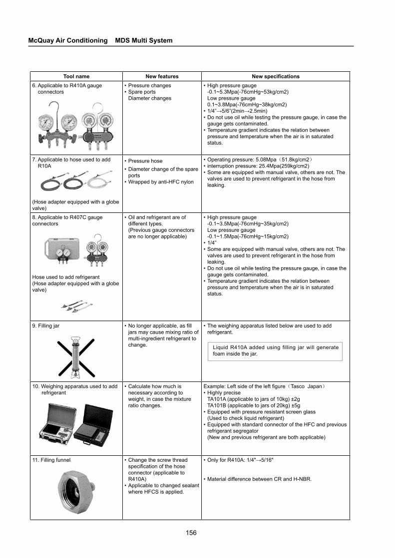
156
McQuay Air Conditioning MDS Multi System
Tool name New features New specifications6. Applicable to R410A gauge
connectorsPressure changesSpare portsDiameter changes
••
High pressure gauge-0.1~5.3Mpa(-76cmHg~53kg/cm2)Low pressure gauge0.1~3.8Mpa(-76cmHg~38kg/cm2)1/4”→5/6”(2min→2.5min)Do not use oil while testing the pressure gauge, in case the gauge gets contaminated.Temperature gradient indicates the relation between pressure and temperature when the air is in saturated status.
•
••
•
7. Applicable to hose used to add R10A
(Hose adapter equipped with a globe valve)
Pressure hose Diameter change of the spare portsWrapped by anti-HFC nylon
••
•
Operating pressure: 5.08Mpa(51.8kg/cm2)interruption pressure: 25.4Mpa(259kg/cm2)Some are equipped with manual valve, others are not. The valves are used to prevent refrigerant in the hose from leaking.
•••
8. Applicable to R407C gauge connectors
Hose used to add refrigerant(Hose adapter equipped with a globe valve)
Oil and refrigerant are of different types.(Previous gauge connectors are no longer applicable)
• High pressure gauge-0.1~3.5Mpa(-76cmHg~35kg/cm2)Low pressure gauge-0.1~1.5Mpa(-76cmHg~15kg/cm2)1/4”Some are equipped with manual valve, others are not. The valves are used to prevent refrigerant in the hose from leaking.Do not use oil while testing the pressure gauge, in case the gauge gets contaminated.Temperature gradient indicates the relation between pressure and temperature when the air is in saturated status.
•
••
•
•
9. Filling jar No longer applicable, as fill jars may cause mixing ratio of multi-ingredient refrigerant to change.
• The weighing apparatus listed below are used to add refrigerant.
Liquid R410A added using filling jar will generate foam inside the jar.
•
10. Weighing apparatus used to add refrigerant
Calculate how much is necessary according to weight, in case the mixture ratio changes.
• Example: Left side of the left figure(Tasco Japan)Highly preciseTA101A (applicable to jars of 10kg) ±2gTA101B (applicable to jars of 20kg) ±5gEquipped with pressure resistant screen glass(Used to check liquid refrigerant)Equipped with standard connector of the HFC and previous refrigerant segregator(New and previous refrigerant are both applicable)
•
•
•
11. Filling funnel Change the screw thread specification of the hose connector (applicable to R410A) Applicable to changed sealant where HFCS is applied.
•
•
Only for R410A: 1/4"→5/16"
Material difference between CR and H-NBR.
•
•

©2010 McQuay International +1 (800) 432-1342 www.mcquay.com
While utmost care is taken in ensuring that all details in the publication are correct at the time of going to press, we are constantly striving for improvement and therefore reserve the right to alter model specifications and equipment without notice.Details of specifications and equipment are also subject to change to suit local conditions and requirements and not all models are available in every market.