multi-modal intelligent traffic signal system · mmitss system design multi-modal intelligent...
TRANSCRIPT

MMITSS System Design
Multi-Modal Intelligent Traffic Signal
System System Design
University of Arizona (Lead)
University of California PATH Program
Savari Networks, Inc.
SCSC
Econolite
Version 1.0
5/25/2013

MMITSS System Design
MMITSS System Design
Page 2 of 30
RECORD OF CHANGES
A – Added, M- Modified, D - Deleted
Version Number
Date Identification of Figure, Table, or
Paragraph Title or Brief Description
Change Request Number
1.0
2/8/2013
N/A
Initial Draft for Team Review/Development
1.1 5/25/2013 Completion of the Software Component descriptions.
2.0 6/26/2013 Modifications in response to Panel review comments

MMITSS System Design
MMITSS System Design
Page 3 of 30
1 Purpose of Document ............................................................................................................................. 5
2 Scope of Project...................................................................................................................................... 5
3 Selected Use Cases for System Development ....................................................................................... 5
4 System Design ........................................................................................................................................ 7
4.1 Physical Architecture ........................................................................................................................ 7
4.1.1 MMITSS Roadside Processor ................................................................................................... 9
4.1.2 RSE Radio ............................................................................................................................... 10
4.2 Software Components .................................................................................................................... 10
4.2.1 Components ............................................................................................................................ 12
4.2.2 Artifacts .................................................................................................................................... 20
5 Appendices ........................................................................................................................................... 21
5.1 Acronyms ....................................................................................................................................... 21
5.2 Appendix A: Savari and Arada RSE Product Specification Sheets ............................................... 23
5.3 Appendix A: Savari OBE Product Specification Sheets ................................................................. 29

MMITSS System Design
MMITSS System Design
Page 4 of 30
List of Figures
Figure 4-1. MMITSS Physical Architecture. .................................................................................................. 8
Figure 4-2. MMITSS Software Components ............................................................................................... 11
List of Tables
Table 3-1. Summary of Down Selected Use Cases for Implementation ...................................................... 5

MMITSS System Design
MMITSS System Design
Page 5 of 30
1 Purpose of Document This document contains the high level system and software design for the Multi-Modal Intelligent Traffic
Signal Systems (MMITSS). The approach taken to the design has been to create a high level component
based design that ensures all of the requirements are addressed by one or more components. The
component based design approach supports both reuse and customization in the software
implementation. Each component can be developed by the best suited team member such that they can
use any desired detailed design approach available to them and define the interfaces that enable
communications with other components. Custom components can be developed where needed, such as
at the controller interface that is different in California and in Arizona. The common components can be
reused in each test network.
2 Scope of Project The Multi-Modal Intelligent Traffic Signal System (MMITSS) project is part of the Cooperative
Transportation System Pooled Fund Study (CTS PFS) entitled “Program to Support the Development and
Deployment of Cooperative Transportation System Applications.” The CTS PFS was developed by a
group of state and local transportation agencies and the Federal Highway Administration (FHWA). The
Virginia Department of Transportation (VDOT) serves as the lead agency and is assisted by the
University of Virginia’s Center for Transportation Studies, which serves as the technical and
administrative lead for the PFS.
The United States Department of Transportation (US DOT) has identified ten high-priority mobility
applications under the Dynamic Mobility Applications (DMA) program for the connected vehicle
environment where high-fidelity data from vehicles, infrastructure, pedestrians, etc. can be shared
through wireless communications. Three of the applications (Intelligent Traffic Signal System, Transit
Signal Priority, and Mobile Accessible Pedestrian Signal System) are related to transformative traffic
signal operations. Since a major focus of the CTS PFS members – who are the actual owners and
operators of transportation infrastructure – lies in traffic signal related applications, the CTS PFS team is
leading the project entitled “Multi-Modal Intelligent Traffic Signal System” in cooperation with US DOT’s
Dynamic Mobility Applications Program.
The MMITSS project is divided into four technical segments. The development of the ConOps, including
the solicitation of Stakeholder inputs and feedback, was the first technical stage. The reviewed
Stakeholder inputs and ConOps were used to develop, define, and populate the MMITSS system
requirements in the second technical stage. In the third stage, the system requirements and prior
research were used to define the MMITSS system design. The design effort will utilize the California Test
Bed and the Maricopa County Test Bed as the target implementation networks. Implementation,
integration, deployment, and test plans based on this design will be defined in the final stage
3 Selected Use Cases for System Development The Concept of Operations and Systems Requirements Documents developed and identified use cases,
functional, and performance requirements that characterize the desired behaviors of MMITSS. Table 3-1
summarizes the use cases that were considered the development of the Concept of Operations. These
use cases have been reviewed to determine which should be included in the Phase II development and
demonstration scope.
Table 3-1. Summary of Down Selected Use Cases for Implementation

MMITSS System Design
MMITSS System Design
Page 6 of 30
Operational Scenarios/Use Cases Include Defer AZ CA
11 MMITSS Operational Scenario
11.0.1 Network Section 1 X X
11.0.2 Network Section 2 X X
11.1 Intelligent Traffic Signal System Scenarios
11.1.1 Basic Signal Actuation X X X
11.1.2 Coordinated Section of Signals X X X
11.1.3 Congestion Control X
11.1.4 Dilemma Zone Protection X X X
11.2 TSP Operational Scenarios
11.2.1 Basic TSP Scenario and Variations X X X
Nearside Bus Stop X
Transit Signal Priority for Left Turn with Protected Signal X
11.2.2 Operational Scenarios for Rail Crossings in Urban Areas X
11.2.3 Extended TSP Scenario X X X
11.3 Pedestrian Mobility Operational Scenarios
11.3.1 Unequipped Non-Motorized Traveler -
11.3.2 Equipped Non-Motorized Traveler X X X
11.3.3 Equipped Bicyclist X
11.3.4 Inclement Weather Accommodations for Non-Motorized Travelers X
11.4 Freight Signal Priority Operational Scenarios
11.4.1 Basic Freight Signal Priority X X X
11.4.2 Coordinated Freight Signal Priority along a Truck Arterial X X X
11.5 Emergency Vehicle Priority
11.5.1 Single Intersection Priority/Preemptions X X
11.5.2 Route Based Intersection Priority/Preemption X
The review of the use cases considered several factors in selecting a fundamental set for inclusion in the
design and development effort (Phase II). The factors include: 1) importance to the demonstration of the
MMITSS concept, 2) feasibility to validate the requirements associated with each use case, 3) technical
feasibility to develop system components to achieve the desired behaviors given the resources available,
and 4) the strengths of the Arizona and California Testbeds in terms of transit, pedestrians, freight, and
emergency vehicles.
Use Cases 11.0.1 and 11.0.2 represent the highest-level goal of MMITSS. That is, to establish a multi-
modal operating policy that provides service to all modes of travel, but provides priority to one or more
modes. For example, Use Case 11.0.1 represents a corridor where freight is favored over transit and
pedestrians. Use Case 11.0.2 represents a corridor where transit and pedestrians are favored over
freight. Emergency vehicles receive priority over all modes in both Use Cases. Arizona was selected for
Use Case 11.0.1 since there is no transit service provided in the network (but transit service can be
demonstrated using simulated buses). The California testbed was selected for Use Case 11.0.2 since
there is transit service (but freight could be simulated if needed).

MMITSS System Design
MMITSS System Design
Page 7 of 30
Use Cases 11.1.1 (Basic Signal Actuation), 11.1.2 (Coordination of Signals) and 11.1.4 (Dilemma Zone
Protection) were selected since they represent the core traffic signal operation Use Cases. 11.1.2
(Coordination of Signals) represents the goal of having MMITSS provide some form of optimizing signal
control. 11.1.1 and 11.1.4 represent the key benefit of being able to track the trajectory of equipped
vehicles as they approach an intersection.
Note that the Congestion Control, Use Case (11.1.3) includes the use of queue length estimation to
terminate a phase that is feeding an oversaturated movement. Other Congestion Control strategies
include reverting to free operation at a congested intersection, and adjustment of the cycle length, splits
and/or phase sequence to coordinate upstream signals to control flow into the congested
intersection/movement. This Use Case was not selected based on the need for a sufficient network
penetration rate of equipped vehicles (e.g. passenger vehicles) in the network to allow accurate traffic
state estimation. This penetration rate is not feasible to achieve within the scope and budget available for
Phase II of this project.
The Use Cases associated with priority control (11.2, 11.4, and 11.5), including transit, freight, and
emergency vehicles, were selected since they represent core MMITSS functionality. All of these Use
Cases utilize the same underlying behavior (e.g. a vehicle sends a request for priority and the
infrastructure determines how priority can be accommodated). Only the basic Transit Priority (TSP) and
extended TSP Use Cases (11.2.1 and 11.2.3) were included. Special behaviors for near side bus stops,
protected left turn priority, and railroad crossings were excluded. Route based priority, or coordinated
corridor priority, for each transit and freight was included despite some concerns about having route
information available. It was assumed that the route information was available for transit routes and
assumed known for freight corridor coordination, and not available for emergency vehicles.
Pedestrian Mobility (Use Case 11.3) was included due to the importance to MMITSS, the feasibility to
validate the requirements, and the technical feasibility of implementation. Pedestrian Mobility is a
significant opportunity for MMITSS to demonstrate the modal interactions. The underlying mechanism of
Pedestrian Mobility is similar to Transit, Freight, and Emergency Vehicles priority, except it requires and
utilizes non-DSRC nomadic devices. This is an important capability of MMITSS that may have wider
implications for large scale deployment in the future.
4 System Design The high level system design is defined by the physical and software components.
4.1 Physical Architecture The Physical MMITSS architecture is shown in Figure 4-1 as a UML Deployment Diagram. This
architecture is based on the Conceptual Architecture identified in the MMITSS Concept of Operations and
MMITSS Systems Requirements documents. In the Unified Modeling Language (UML), nodes are shown
as 3D blocks and represent physical devices that have a processor (at least one), memory, and physical
interfaces (e.g. Ethernet, RS-232, or wireless – 3G/4G, 5.9GHz DSRC, or other such as CAN-bus).

MMITSS System Design
MMITSS System Design
Page 8 of 30
Figure 4-1. MMITSS Physical Architecture.
The nodes have been shaded such that the light colored nodes are part of the connected vehicle system,
Traffic Management and Fleet Management systems (or nodes that can be modified or assigned MMITSS
responsibilities) and the gray colored nodes represent the vehicles and travelers. The orange colored
nodes are the MMITSS Central System and Nomadic Traveler Server as described below. These two
nodes may be realized as a single node for the testbed implementations.
In this view of the system, there are two types of travelers – motorized vehicles and non-motorized
travelers. Motorized vehicles consist of passenger vehicles, trucks, transit vehicles, emergency vehicles,
and motorcycles. This type of traveler includes any vehicle that must be licensed to operate on the public
roadway. Non-motorized travelers include pedestrians, bicyclists, and other modes such as equestrians
that are not required to be licensed to operate on the public roadway. These travelers are either
unequipped or equipped, meaning that they have some type of OBE (On-Board Equipment) or nomadic
device that is connected vehicle (or MMITSS) aware and can operate as part of the traffic control system.
Motorized vehicles can be part of a fleet management system such as a transit management system,
commercial freight management system, emergency vehicle dispatch system, and taxi dispatch, which is
shown as a UML collaboration (oval in Figure 4-1) meaning that a collection of entities work together to
perform the traffic management functions, but there may be many different systems involved in this
collaboration.

MMITSS System Design
MMITSS System Design
Page 9 of 30
The infrastructure based traffic signal control equipment consists of the traffic signal controller, field
sensors/detectors, and a MMITSS Roadside Processor (MRP). There are two traffic signal controllers
models that will be utilized in the field installation: Econolite ASC/3 (NTCIP) (AZ) and Type 2070 (Caltrans
– AB3418) (CA). Each of these controllers offers different signal timing logic (software) and require
different communications interfaces. The Econolite ASC/3 controllers are based on NEMA standards and
support NTCIP over Ethernet communications. The Caltrans Type 2070 controllers are based on a
Caltrans standard and support AB3418 over serial RS-232 communications. Both networks utilize loop
detectors for vehicle detection. The MMITSS Roadside Processor was included in the architecture to
allow the RSE to provide a pure communications role in the systems. The MRP is a Linux based general-
purpose computer (see Section 4.1.1 below for details).
The RSE Radio is the hardware device that is responsible for managing all of the 5.9GHz DSRC
communications between the vehicles and the infrastructure. The Arizona network utilizes Savari RSE
units. The California utilizes both Savari and Arada RSE units. (see Section 4.1.2 below for details).
The OBE is a hardware device deployed on the vehicle. MMITSS will be developed and tested using
Savari MobilWave units for the OBE. These units are general purpose and provide a powerful and flexible
platform for development and testing. The product data sheet for the OBE is in Appendix A: Savari OBE
Product Specification Sheets.
The larger traffic management system is shown as a UML collaboration in Figure 4-1. The RSE is a
general communications processing node that coordinates messages from the various modes of
travelers. The MMITSS Roadside Processor (MRP) is a general purpose computer that hosts the core
intersection level infrastructure applications for MMITSS. The RSE contains (deploys) the MAP artifact,
which is the digital description of the intersection geometry and associated traffic control definitions.
Both motorized and non-motorized travelers can be detected by the Field Sensor/Detector node at the
intersections using a variety of detection technologies, including inductive loop detectors, video detection,
microwave, radar, pedestrian push button, etc. The detection system at an intersection provides
information to the traffic signal controller that stimulates the control algorithms. For example, a vehicle
that triggers a detector will call a signal control phase for service or extension. A pedestrian may activate
a pedestrian push button to request the traffic signal pedestrian interval associated with a crosswalk
movement.
Each of the systems that can be active participants in the MMITSS (e.g., connected vehicle, Traffic
Management, and Fleet Management) can have different responsibilities, and in alternative system
designs some of these responsibilities can be assigned to different components. In the discussion
presented here, the basic operating functions will be reviewed and the alternative assignments will be
explored in the detail design effort.
4.1.1 MMITSS Roadside Processor
The MMITSS Roadside Processor (MRP) selected for the California test network is described by the following specification:
Jetway NF9E-Q77 Mini-ITX Motherboard, Q77 Express vPro iAMT, LGA1155, Ivy
Bridge
Enclosure, power supply: Super Case MI-100BK Mini-ITX Case

MMITSS System Design
MMITSS System Design
Page 10 of 30
Digital I/O board: PCIe-IIRO-8
CPU chipset, fan: Intel Core i5-3570 Ivy Bridge 3.4GHz (3.8GHz Turbo
Boost) LGA 1155 77W Quad-Core Desktop Processor Intel HD Graphics 2500
BX80637i53570
Disk drive: Seagate Constellation ES ST500NM0011 500GB 7200 RPM 64MB
Cache SATA 6.0Gb/s 3.5" Enterprise Internal Hard Drive -Bare Drive
System memory: Transcend 8GB (2 x 4GB) 240-Pin DDR3 SDRAM DDR3 1333
Desktop Memory Model JM1333KLN-8GK
Operating System: Ubuntu Server 12.04.2 LTS
These components will be assembled into a field deployable roadside device. [Note: this processor is
planned for deployment in the California testbed. The temperature range of these units has a maximum
range of 140F. There is some concern about the use of this design in the Arizona testbed].
4.1.2 RSE Radio
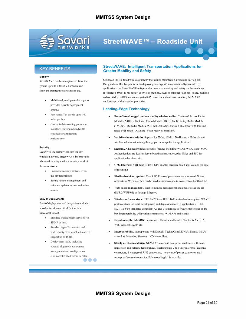
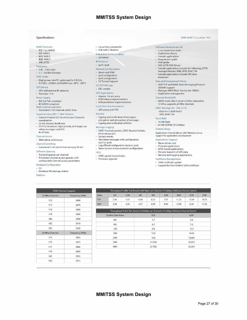
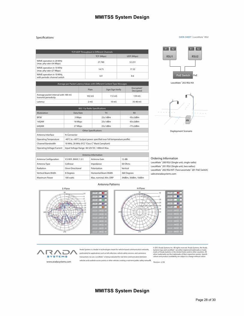
Two RSE Radios have been selected for this project: Savari Streetwave (3.1) and Arada LocoMate. The
Arizona testbed uses the Savari units. The California testbed used both Savari and Arada units. Both
units support two 5.9GHz DSRC radios and an Ethernet interface for communications. The product spec
sheets are available in Appendix A: Savari and Arada RSE Product Specification Sheets.
4.2 Software Components Figure 4-2 shows the primary software components of MMITSS. The software is grouped according to the
deployment nodes. The OBE (on-board equipment) is deployed on each equipped vehicle. The
OBE_name software components provide the functionality required of the OBE. The OBE communicates
with the RSE (roadside equipment) over the DSRC WAVE channel. The RSE_name software
components provide the key wireless communication behaviors including sending and receiving
messages, as well as the Service Advertisement and Security Certificate services. The MMITSS
Roadside Processor communicates with the RSE using local Ethernet network, and with the MMITSS
Central System and the Nomadic Traveler Service using a combination of field and backhaul
communications. In the Marcopa County SMARTDrive network a fiber optic local network is provided
between all of the test intersections and a wireless backhaul connection is provided from the field to the
MCDOT traffic operations center (TOC). In the California Test Network, field communications is managed
through a field master that communicates with each intersection controller over multi-drop serial
communications. The field master has backbone access to the traffic operations center. The MMITSS
Roadside Processor also communicates to the intersection traffic signal controller. The MMITSS
Roadside Processor hosts software components that perform the core intersection level functions of
MMITSS. These components include the MAP and SPaT broadcast manager, the equipped vehicle
tracker, the priority request server, traffic control logic, the interface to the traffic signal controller (AB3418
or NTCIP), and the components that communicate status to the Nomadic Traveler Service including
status and nomadic device tracking. The MMITSS Roadside Processor also hosts the performance
observer component.

MMITSS System Design
Figure 4-2. MMITSS Software Components

MMITSS System Design
The MMITSS Central system hosts software components that provide a user interface, configuration
manager, N-level priority policy configuration manager, and section level priority server and signal
coordination. The MMITSS Central system also hosts the section and system level performance
observers.
The Nomadic Traveler Service hosts two software components that provide the priority data service that
relays intersection data (e.g. MAP and SPaT data) to nomadic devices and receives requests for
service/priority from nomadic devices. The Nomadic Traveler Service also hosts the security and
authorization service for nomadic devices that ensures these devices are associated with valid users and
are authorized to receive special service if the user is a disabled pedestrian.
The Nomadic device is assumed to be a smart phone, either ios or Android based, and hosts an
applications (app) that uses two components. One component requests service/priority and the other
collects and makes status information available for display on the app.
4.2.1 Components
This section contains a summary of each of the software components in terms of their responsibility as
defined by the associated requirements and description in the concept of operations document. Each
component is given a name, traceability information to requirements, concept of operations, and/or
stakeholder requirements, a brief description of the components responsibility, and any additional text
useful for understanding the components role in MMITSS.
4.2.1.1 Road Side Equipment (RSE)
Node: RSE Component Name: RSE_SecurityCertificateService
Traceability: System Requirements Section 6.6.3
Description of Responsibility: This component is responsible for providing security services on the RSE. It is responsible for ensuring eligible equipped vehicles (OBE) can receive security credentials and for ensuring BSM messages are received from authorized users.
Supporting Text: The RSE_SecurityCertificateService will have a connection to a Certificate Server that will provide the security certificates for the equipped vehicles. When an eligible vehicle (OBE) requests a security certificate, the RSE will issue the certificate. The RSE will maintain a collection of certificates to be issued and will get new certificates from the Certificate Service as needed.
Node: RSE Component Name: RSE_ServiceAdvertisementMgr
Traceability: System Requirements Section 6.6.2
Description of Responsibility: This component is responsible for broadcasting a service advertisement message over a WAVE control channel that include information about the intersection ID, the MAP (GID) version number, and the service channel used for broadcasting the full MAP and GPS corrections.
Supporting Text: The RSE_ServiceAdvertisementMgr broadcasts a service advertisement so that approaching vehicles will be aware of the MMITSS Traffic Control application(s) that are available. Vehicles that receive the advertisement will be instructed to switch communication channels to receive application specific information.
Node: RSE Component Name: RSE_MessageTX
Traceability: C2009.001, Use Case 11.2.1.1

MMITSS System Design
MMITSS System Design
Page 13 of 30
Description of Responsibility: This component is responsible for transmitting properly formatted messages over a specified WAVE channel.
Supporting Text: The RSE_MessageTX component is responsible for transmitting properly formatted SAE J2735 messages over a specified (or appropriate) WAVE channel. Example messages would include the Signal Status Message (SSM), Emergency Vehicle Alert (EVA), etc.
Node: RSE Component Name: RSE_MessageRX
Traceability: C2001.001 (All vehicle data acquired by RSE through the WAVE communications)
Description of Responsibility: This component is responsible for receiving properly formatted messages over a specified WAVE channel.
Supporting Text: The RSE_MessageRX component is responsible for receiving properly formatted SAE J2735 messages over a specified (or appropriate) WAVE channel. Example messages would include the Basic Safety Message (BSM), Signal Request Message (SRM), etc.
4.2.1.2 On-Board Equipment (OBE)
Node: OBE Component Name: OBE_SecurityService
Traceability: System Requirements Section 6.6.3
Description of Responsibility: This component is responsible for ensuring that OBE’s receive authenticated messages from the infrastructure (and/or other vehicles) and that the OBE has proper security credentials for transmitting messages.
Supporting Text: The security requirements for connected vehicle systems have been determined outside the MMITSS project, but they need to be fully implemented and operational for MMITSS field deployment.
Node: OBE Component Name: OBE_BSMData_Transmitter
Traceability: C2001.001, 13.3.1, 13.3.2, 13.3.4, 13.3.5; §5, §8, §11.1.1,
§11.1.3, §11.2.1, §11.4.1, §11.5.1
Description of Responsibility: The OBE_ BSMData_Transmitter is responsible for collecting vehicle data from the GPS receiver and vehicle data systems (CAN bus) and formatting the data into a J2735 BSM Message.
Supporting Text: This component is responsible for getting vehicle data, GPS data, and forming the BSM message. (Part 1 and Part 2 as data is available). The OBE_BSMData_Transmitter component is responsible for broadcasting the data.
Node: OBE Component Name: OBE_MAP_SPaT_Receiver
Traceability: A1002, 13.3.1, 13.3.2, 13.3.4, 13.3.5; §5, §8, §11.1
Description of Responsibility: The OBE_MAP_SPaT_Receiver is responsible for listening for the MAP and SPaT messages and making the received data available to the other OBE components.
Supporting Text: The MAP and SPaT data are critical to the vehicle component related to requesting priority.
Node: OBE Component Name: OBE_PriorityRequestGenerator

MMITSS System Design
MMITSS System Design
Page 14 of 30
Traceability: C1003.201, C1003.402, C1003.503, C1004.201, C1004.402, C1004.503, A2501, Use Case 13.3.2; Use Case 13.3.4; Use Case 13.3.5; §4, §4.1.2, §4.1.4, §4.1.5, §5, §9.3.4, §11.0, §11.0.1, §11.0.2, §11.2, §11.4, §11.5; 11.5.1;
Description of Responsibility: The OBE_PriorityRequestGenerator is a critical MMITSS component that is responsible for determining a vehicles eligibility for priority, the level of priority to request, determining the response mode of emergency vehicles, estimating the desired service time (e.g. estimated time of arrival at the stop bar). It is also responsible for updating any of the request information if there is a change in status or data.
Supporting Text: The OBE_PriorityRequestGenerator is an important and active component on the vehicle that is responsible for determining eligibility, level, desired time, and service phase or approach. The OBE may require communications with a fleet management system (external to MMITSS) or may have the priority policy information pre-programmed. All vehicles that are active in the requesting of
Node: OBE Component Name: OBE_GUI
Traceability: System Requirements Section 6.3 (General Interface Requirements)
Description of Responsibility: OBE_GUI component is responsible for providing a human interface to the OBE so that the developers can visualize the data used by the OBE processes including vehicle data and priority request data.
Supporting Text: The ability to visualize the status of the OBE components is important in the development, testing, and demonstration of the MMITSS system. In previous efforts (e.g. the MCDOT SMARTDrive demonstration in Arizona on April 26, 2012) a web page interface was used to display data. While this interface was effective, there were issues related to latency between the webserver on the OBE and the device (iPad) used to display the data. This component should address the latency issues by improving the data processing and communications capabilities. It is intended to use an iPad mini for the display purpose. A wireless connection between the OBE and the iPad mini will be used for communications and a native display application will be used instead of web pages. The use of an application instead of a web page will reduce the latency by ensuring more reliable and frequent requests for data and communication of data. The display of data will be immediate and not limited to the sub set of html capabilities that are available on tablet devices. The iPad Mini (ios) device was selected based on the teams experience in app development. This design decision will be evaluated in the Phase II Detail Design effort.
4.2.1.3 MMITSS Roadside Processor (MRP)
Node: MRP Component Name: MRP_MAP_SPaT_Broadcast
Traceability: C2004.001, C2005.001, C2005.302, 13.3.1, 13.3.2, 13.3.3, 13.3.4, 13.3.5; §4.1.3, §5, §8, §9.1, §11.0, §11.2.1, §11.3, §11.4.1, §11.5.1
Description of Responsibility: This component is responsible for collecting information that composes the SPaT message from the signal controller and forming the SPaT message to be broadcast and for managing the MAP data that is broadcast. The MAP and SPaT data will be sent to the RSE_MessageTX component on the RSE for broadcast.
MMITSS System Design
MMITSS System Design
Page 15 of 30
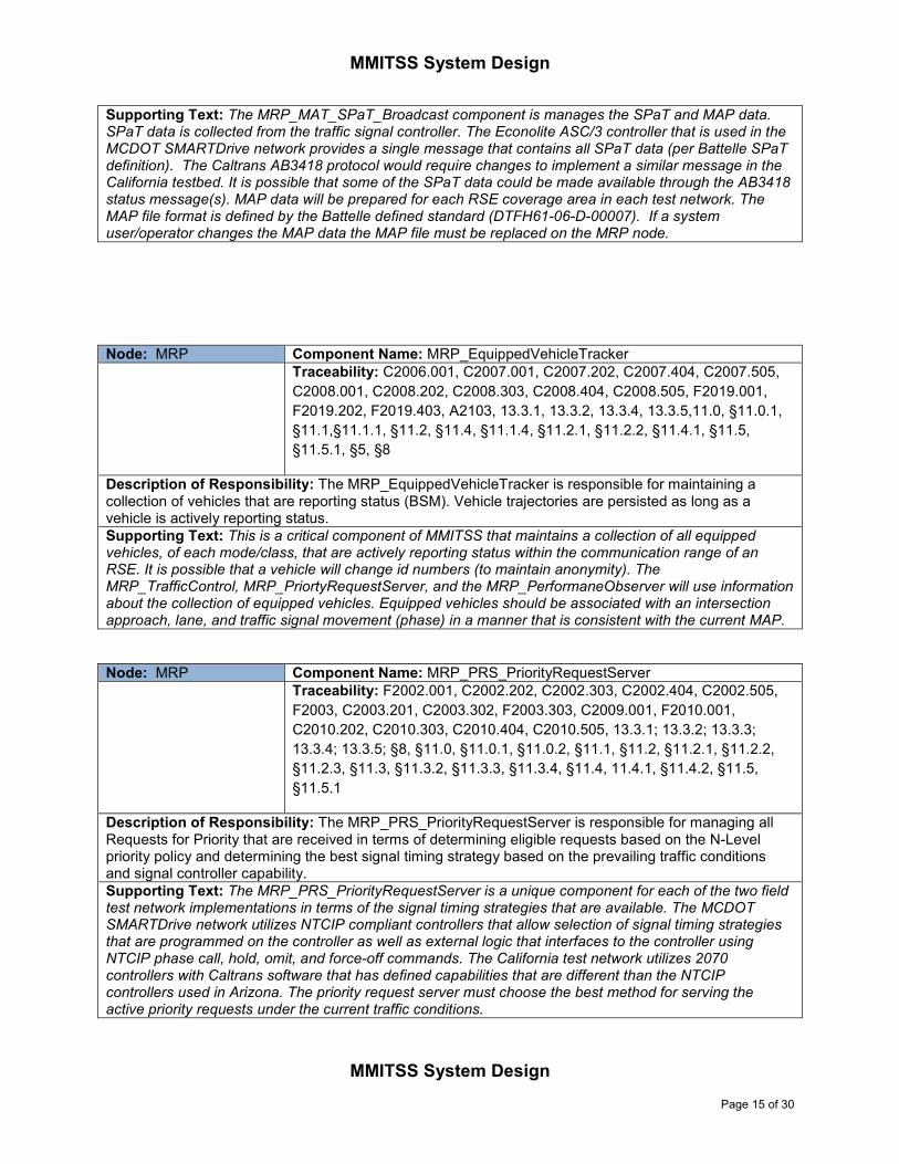
Supporting Text: The MRP_MAT_SPaT_Broadcast component is manages the SPaT and MAP data. SPaT data is collected from the traffic signal controller. The Econolite ASC/3 controller that is used in the MCDOT SMARTDrive network provides a single message that contains all SPaT data (per Battelle SPaT definition). The Caltrans AB3418 protocol would require changes to implement a similar message in the California testbed. It is possible that some of the SPaT data could be made available through the AB3418 status message(s). MAP data will be prepared for each RSE coverage area in each test network. The MAP file format is defined by the Battelle defined standard (DTFH61-06-D-00007). If a system user/operator changes the MAP data the MAP file must be replaced on the MRP node.
Node: MRP Component Name: MRP_EquippedVehicleTracker
Traceability: C2006.001, C2007.001, C2007.202, C2007.404, C2007.505,
C2008.001, C2008.202, C2008.303, C2008.404, C2008.505, F2019.001,
F2019.202, F2019.403, A2103, 13.3.1, 13.3.2, 13.3.4, 13.3.5,11.0, §11.0.1,
§11.1,§11.1.1, §11.2, §11.4, §11.1.4, §11.2.1, §11.2.2, §11.4.1, §11.5,
§11.5.1, §5, §8
Description of Responsibility: The MRP_EquippedVehicleTracker is responsible for maintaining a collection of vehicles that are reporting status (BSM). Vehicle trajectories are persisted as long as a vehicle is actively reporting status.
Supporting Text: This is a critical component of MMITSS that maintains a collection of all equipped vehicles, of each mode/class, that are actively reporting status within the communication range of an RSE. It is possible that a vehicle will change id numbers (to maintain anonymity). The MRP_TrafficControl, MRP_PriortyRequestServer, and the MRP_PerformaneObserver will use information about the collection of equipped vehicles. Equipped vehicles should be associated with an intersection approach, lane, and traffic signal movement (phase) in a manner that is consistent with the current MAP.
Node: MRP Component Name: MRP_PRS_PriorityRequestServer
Traceability: F2002.001, C2002.202, C2002.303, C2002.404, C2002.505,
F2003, C2003.201, C2003.302, F2003.303, C2009.001, F2010.001,
C2010.202, C2010.303, C2010.404, C2010.505, 13.3.1; 13.3.2; 13.3.3;
13.3.4; 13.3.5; §8, §11.0, §11.0.1, §11.0.2, §11.1, §11.2, §11.2.1, §11.2.2,
§11.2.3, §11.3, §11.3.2, §11.3.3, §11.3.4, §11.4, 11.4.1, §11.4.2, §11.5,
§11.5.1
Description of Responsibility: The MRP_PRS_PriorityRequestServer is responsible for managing all Requests for Priority that are received in terms of determining eligible requests based on the N-Level priority policy and determining the best signal timing strategy based on the prevailing traffic conditions and signal controller capability.
Supporting Text: The MRP_PRS_PriorityRequestServer is a unique component for each of the two field test network implementations in terms of the signal timing strategies that are available. The MCDOT SMARTDrive network utilizes NTCIP compliant controllers that allow selection of signal timing strategies that are programmed on the controller as well as external logic that interfaces to the controller using NTCIP phase call, hold, omit, and force-off commands. The California test network utilizes 2070 controllers with Caltrans software that has defined capabilities that are different than the NTCIP controllers used in Arizona. The priority request server must choose the best method for serving the active priority requests under the current traffic conditions.

MMITSS System Design
MMITSS System Design
Page 16 of 30
Node: MRP Component Name: MRP_TrafficControl
Traceability: C2011.001, C2011.302, C2011.303, C2011.304, C2011.005,
C2011.006, C2012.001, C2012.002, C2014.001, C2101.001, C2101.002,
C2101.003, C2101.004, C2101.305, A2106, 13.3.1, 13.3.2, 13.3.3, 13.3.4,
13.3.5; §11.0, §11.0.2, §11.1.1, §11.1.1.2, §11.1.1.3, §11.1.4, §11.2.1,
§11.2.2, §11.2.3, §11.3, §11.3.2, §11.3.3, §11.4.1, §11.5.1, §12.7.1, §5, §8
Description of Responsibility: The MRP_TrafficControl is responsible for integrating all equipped vehicles from the MRP_EquippedVehicleTracker into the traffic control logic through detection matching, phase calls, phase extensions, dilemma zone protection for each of the different modes (and dynamics) of vehicles.
Supporting Text: The MRP_TrafficControl component is a unique component for each of the two field test network implementations in terms of the capabilities of the controller features that are supported. The MCDOT SMARTDrive network utilizes NTCIP compliant controllers that allow data acquisition, including detector calls, phase status, etc., and control using NTCIP objects. The California test network utilizes 2070 controllers with Caltrans software that has defined capabilities that are different than the NTCIP controllers used in Arizona.
Node: MRP Component Name: MRP_TrafficControllerInterface
Traceability: C2011.001, C2011.302, C2011.303, C2011.304, C2011.005, C2011.006, C2012.001, C2012.002, C2014.001, C2101.001, C2101.002, C2101.003, C2101.004, C2101.305, A2106, 13.3.1, 13.3.2, 13.3.3, 13.3.4, 13.3.5; §11.0, §11.0.2, §11.1.1, §11.1.1.2, §11.1.1.3, §11.1.4, §11.2.1, §11.2.2, §11.2.3, §11.3, §11.3.2, §11.3.3, §11.4.1, §11.5.1, §12.7.1, §5, §8
Description of Responsibility: This component is responsible for providing the protocol specific interface to the traffic signal controller.
Supporting Text: The MRP_TrafficControllerInterface component is a unique component for each of the two field test network implementations in terms the protocol supported for communications. The MCDOT SMARTDrive network uses NTCIP controllers over wired Ethernet. The California network uses controllers that use the AB3418 protocol over serial multi-drop communications. This component will provide the necessary protocol specific interfaces including messages and channel control/management capabilities.
Node: MRP Component Name: MRP_SignalStatusNomadic
Traceability: C2004.302, C2009.302, A1301, A1302, 13.3.3; §5, §8, §11.0,
§11.1, §11.3, §11.3.2
Description of Responsibility: This component is responsible for collecting a subset of the SPaT data
and forwarding it to the Nomadic Traveler Server so that nomadic devices can receive signal status data.
Supporting Text: The signal status data to be sent to nomadic devices is a subset of the SPaT data.
This data is to be sent to the Nomadic Traveler Server where it can be distributed to Nomadic devices.
The signal status data required by the nomadic device includes, but is not limited to, the current signal
interval status (e.g. vehicle green, pedestrian walk, pedestrian clearance, pedestrian don’t walk, yellow,
red, and countdown information – remaining time in pedestrian don’t walk interval).
Node: MRP Component Name: MRP_NomadicDeviceTracker
MMITSS System Design
MMITSS System Design
Page 17 of 30
Traceability: C2006.302, F2006.003, C2001.302, 13.3.1, 13.3.2, 13.3.3,
13.3.4, 13.3.5; §8, §11.0, §11.1.1, §11.1.4, §11.2.1, §11.2.2, §11.3.2,
§11.3.3, §11.4.1, §11.5.1
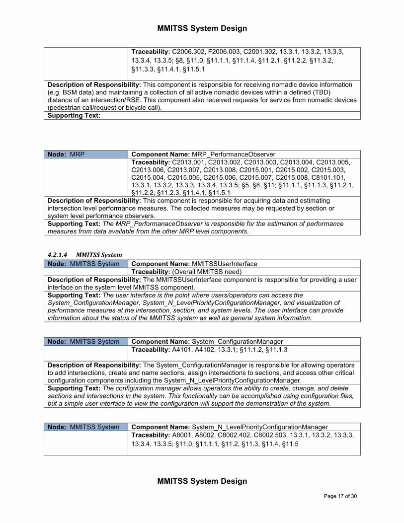
Description of Responsibility: This component is responsible for receiving nomadic device information (e.g. BSM data) and maintaining a collection of all active nomadic devices within a defined (TBD) distance of an intersection/RSE. This component also received requests for service from nomadic devices (pedestrian call/request or bicycle call).
Supporting Text:
Node: MRP Component Name: MRP_PerformanceObserver
Traceability: C2013.001, C2013.002, C2013.003, C2013.004, C2013.005, C2013.006, C2013.007, C2013.008, C2015.001, C2015.002, C2015.003, C2015.004, C2015.005, C2015.006, C2015.007, C2015.008, C8101.101, 13.3.1, 13.3.2, 13.3.3, 13.3.4, 13.3.5; §5, §8, §11; §11.1.1, §11.1.3, §11.2.1, §11.2.2, §11.2.3, §11.4.1, §11.5.1
Description of Responsibility: This component is responsible for acquiring data and estimating intersection level performance measures. The collected measures may be requested by section or system level performance observers.
Supporting Text: The MRP_PerformanaceObserver is responsible for the estimation of performance measures from data available from the other MRP level components.
4.2.1.4 MMITSS System
Node: MMITSS System Component Name: MMITSSUserInterface
Traceability: (Overall MMITSS need)
Description of Responsibility: The MMITSSUserInterface component is responsible for providing a user interface on the system level MMITSS component.
Supporting Text: The user interface is the point where users/operators can access the System_ConfigurationManager, System_N_LevelPrioriityConfigurationManager, and visualization of performance measures at the intersection, section, and system levels. The user interface can provide information about the status of the MMITSS system as well as general system information.
Node: MMITSS System Component Name: System_ConfigurationManager
Traceability: A4101, A4102, 13.3.1; §11.1.2, §11.1.3
Description of Responsibility: The System_ConfigurationManager is responsible for allowing operators to add intersections, create and name sections, assign intersections to sections, and access other critical configuration components including the System_N_LevelPriorityConfigurationManager.
Supporting Text: The configuration manager allows operators the ability to create, change, and delete sections and intersections in the system. This functionality can be accomplished using configuration files, but a simple user interface to view the configuration will support the demonstration of the system.
Node: MMITSS System Component Name: System_N_LevelPriorityConfigurationManager
Traceability: A8001, A8002, C8002.402, C8002.503, 13.3.1, 13.3.2, 13.3.3,
13.3.4, 13.3.5; §11.0, §11.1.1, §11.2, §11.3, §11.4, §11.5

MMITSS System Design
MMITSS System Design
Page 18 of 30
Description of Responsibility: This component is responsible for allowing an operator to set the policy preferences for the N-Level Priority policy.
Supporting Text: In each section, the decision makers define a preference for granting priority to different classes of vehicles, such as BRT transit is more important that Express transit and transit is more important than trucks or in another section trucks are more important than transit. The System_N_LevelPriorityConfigurationManager is the mechanism where an operator can configure the policy. Given a policy setting, the configuration manager will set the associated parameters on the MRP and within section level priority request servers.
Node: MMITSS System Component Name: Section_PriorityRequestServer
Traceability: C3001.202, C3001.403, C3001.504, C4003.201, C4003.402,
A4004, C4004.201, 13.3.2; 13.3.4; 13.3.5; §11.0, §11.0.1, §11.0.2, §11.2,
§11.2.3, §11.4, §11.4.2, §11.5
Description of Responsibility: This component is responsible for implementing section level priority control based on requests for priority that are acquired from the intersections.
Supporting Text: Section level priority strategy may include coordination of signals to provide priority for emergency vehicles, or transit/trucks. Typically these strategies include coordination changes (e.g. offsets), queue clearance, or creation of green bands. The N-level priority policy is used to determine which modes/classes of vehicles are given preference over other mode/classes of vehicles.
Node: MMITSS System Component Name: Section_Coordinator
Traceability: C3003.001, C3003.002, C3003.003, C3003.004, C3003.005,
C3003.006, A3004, C3005.001, C3005.002, A3006, A3101, C3101.001,
C3102.001, C3102.002, A3103, 11.1.2; 13.3.1, 13.3.2, 13.3.3, 13.3.4, 13.3.5;
§4.1.1, §4.2, §5, §11.0, §11.1.2, §11.4.2, §11.5.2
Description of Responsibility: This component is responsible for the identification of platoons, estimation of the platoon arrival time at intersections in the section, setting offsets and coordinated phase splits.
Supporting Text: The Section_Coordinator provides adjustments to coordination timing that considers the movement/progression of platoons within the priority framework. Trade-offs between priority for different modal vehicles and coordination is part of the N-level priority policy.
Node: MMITSS System Component Name: Section_PerformanceObserver
Traceability: C3002.001, C3002.002, C3002.003, C3002.004, C3002.005,
C3002.006, C3002.007, C3002.008, C8101.102, §11, 11.1.2 (13.3.1), §12.7"
Description of Responsibility: This component is responsible for acquiring intersection performance estimates and combining them with section level data to estimate section level performance measures.
Supporting Text: Section level performance measures utilize intersection level measures together with section leve information (e.g. platoon size, head, tail, stops, travel time, etc.) to provide estimates of section level performance.

MMITSS System Design
MMITSS System Design
Page 19 of 30
Node: MMITSS System Component Name: System_PerformanceObserver
Traceability: A4103, C4103.001, C4103.002, C4103.003, C4103.004,
C4103.405, C4103.006, C4103.007, C8101.103, 11.1.2 (13.3.1), 13.3.2,
13.3.4, 13.3.5; §11.0, §11.2.3, §12.7
Description of Responsibility: The System_PerformanceObserver is responsible for acquiring performance estimates from the sections and providing system level performance estimates.
Supporting Text: System level performance measurement estimates include network level travel time, delay, stops, throughput, and variability of these measures. These are aggregated performance measures aimed at characterizing how an entire system is operating.
4.2.1.5 Nomadic Device
Node: Nomadic Device Component Name: Nomadic_PriorityRequestGenerator
Traceability: C1303.302
Description of Responsibility: This component on the nomadic device is responsible for formulating and sending a request for service/priority from the nomadic device.
Supporting Text: The Nomadic_PriorityRequestGenerator is analogous to the OBE based priority request generator, with the additional capability of using the nomadic devices location services for determining the location and orientation of the device.
Node: Nomadic Device Component Name: Nomadic_SignalStatusReceiver
Traceability: A1301, A1302, 13.3.3; §5, §8, §11.1, §11.3"
Description of Responsibility: This component is responsible for receiving signal status data from an intersection and making the data available to the NomadicMMITSSApp.
Supporting Text: This is the analogous component to the OBE_MAP_SPaT_Receiver for the nomadic device. It is responsible for receiving status data and making it available to the app.
Node: Nomadic Device Component Name: NomadicMMITSSApp
Traceability: A1303, 13.3.3; §4, §4.1.5, §5, §9.3.4, §11.0, §11.0.1, §11.0.2,
§11.3
Description of Responsibility: The NomadicMMITSS App is a downloadable app that individuals can install on their nomadic device. It is the base application for the nomadic device.
Supporting Text: It is assumed that the Nomadic Device is a smartphone (ios based or android based) and that users will be able to download the app to their device. The app provides the functionality available to the nomadic device including knowing how to connect to the Nomadic_PriorityDataServer to get status data and send requests for service. The Nomdic Device app can be configured to indicate that a user (pedestrian) is disabled, authorized, and provided additional crossing time if needed. The MMITSS Team is planning to leverage the Phase II SBIR Project 11.1-FH1-008 SmartCross – Traffic Signal Interface on the Smartphone for the application development. This project includes both ios and android applications. MMITSS will ensure an ios version is developed since Savari (prime on SBIR project) has an android version developed as part of the Phase I proof of concept.
MMITSS System Design
MMITSS System Design
Page 20 of 30
4.2.1.6 Nomadic Server
Node: Nomadic Server Component Name: Nomadic_PriorityDataServer
Traceability: C1303.302
Description of Responsibility: This component is responsible for acquiring infrastructure data and providing it to nomadic devices using wireless 3G/4G, LTE, and/or wifi.
Supporting Text: Infrastructure data, including the MAP, SPaT, Signal Status Messages, etc. needs to be relayed from the MPR to the nomadic device through a cloud based (or server based) capability. The Nomadic_PriorityDataServer is responsible for providing this service. This component will host data for all (many) intersections and the nomadic device will request data (using the NomadicMMITSS App) based on the devices location.
Node: Nomadic Server Component Name: AuthroizedSpecialUserService
Traceability: C1303.301, C1303.302
Description of Responsibility: This component is responsible for ensuring that nomadic devices are authorized participants in the MMITSS system and to authorize special service for pedestrians with a disability.
Supporting Text: This service is required to ensure unauthorized devices do not request service or have any other impact on the MMITSS system. Special users, e.g. pedestrians with disabilities, are required to have special authorization before being allowed to request extra crossing time.
4.2.2 Artifacts
4.2.2.1 MAP Data
The key artifact in the MMITSS system is the MAP. The MAP is deployed on the MRP and distributed to
vehicles and travelers using the RSE and Nomadic server. The format of the MAP data is defined in
• Signal Phase And Timing And Related Messages For V-I Applications, Concept of
Operations, Document No. 60606-012c.
There should be a minimum of one MAP defined for each intersection in the MMITSS systems,
but it is possible that there may be more than one map depending on operational factors such
as time-of-day differences or temporary closures for repairs, etc.

MMITSS System Design
5 Appendices
5.1 Acronyms ABSM Alternate Basic Safety Message AC Alternating Current ADA Americans with Disabilities Act (1990) AQ Air Quality APS Accessible Pedestrian Signals ASC Actuated Signal Controller ATIS Advanced Traveler Information Systems ATDM Active Traffic and Demand Management ATV All-Terrain Vehicle BRT Bus Rapid Transit BSM Basic Safety Messages CA California CDRL Contract Deliverables Requirements List CMMI Capability Maturity Model Integration CONOPS Concept of Operations CTS Cooperative Transportation System CV Connected Vehicle DC Direct Current DMA Dynamic Mobility Applications DOORS Dynamic Object Oriented Requirement System DOT Department of Transportation DSRC Dedicated Short Range Communication EMS Emergency Medical/Management Services ESD Electro-static Discharge ETA Estimated Time of Arrival EV Emergency Vehicle EVP Emergency Vehicle Preemption FHWA Federal Highway Administration FOM Figure of Merit FPS Feet Per Second FTA Federal Transit Administration FYA Flashing Yellow Arrow GID Geometric Intersection Description GPS Global Positioning Systems IC Information Center ID Identification IM Incident Management INCOSE International Council on Systems Engineering ISIG Intelligent Traffic Signal System ITS Intelligent Transportation System LOS Level of Service MD Maryland MHz Megahertz (10
6 Hertz)
MMITSS Multi-Modal Intelligent Traffic Signal System MOE Measures of Effectiveness MPH Miles Per Hour MRP MMITSS Roadside Processor MTBF Mean Time Between Failure MTTF Mean Time to Failure

MMITSS System Design
MMITSS System Design
Page 22 of 30
NHTSA National Highway Traffic Safety Administration NTCIP National Transportation Communications for ITS Protocol OBE On-Board Equipment OD Origin-Destination OEM Original Equipment Manufacturer PATH Partners for Advanced Transportation Technology PFP Pooled Fund Project PFS Pooled Fund Study PI Principal Investigator PII Personally Identifiable Information PMPP Point to Multi-Point Protocol POV Privately Owned Vehicle R&D Research and Development RSE Roadside Equipment RV Recreational Vehicle SE Systems Engineering SPaT Signal Phase and Timing SRM Signal Request Message SSM Signal Status Message STMP Simple Transportation Management Protocol SVN Subversion (PFP Repository with Version Control) SyRS System Requirements TMDD Traffic Management Data Dictionary TSC Traffic Signal Controller TSP Transit Signal Priority UA University of Arizona UC University of California UML Unified Modeling Language USDOT United States Department of Transportation V2I Vehicle-to-Infrastructure V2V Vehicle-to-Vehicle VDOT Virginia Department of Transportation VMT Vehicle Miles Traveled

MMITSS System Design
5.2 Appendix A: Savari and Arada RSE Product Specification Sheets
MMITSS System Design
MMITSS System Design
Page 24 of 30
KEY BENEFITS
Mobility:
StreetWAVE has been engineered from the
ground up with a flexible hardware and
software architecture for outdoor use.
• Multi-band, multiple radio support
provides flexible deployment
options.
• Fast handoff at speeds up to 100
miles per hour.
• Customizable roaming parameter
maintains minimum bandwidth
required for application
performance.
Security:
Security is the primary concern for any
wireless network. StreetWAVE incorporates
advanced security methods at every level of
the transmission.
• Enhanced security protects over-
the-air transmission.
• Secure remote management and
software updates ensure authorized
access.
Easy of Deployment:
Ease of deployment and integration with the
wired network are critical factors in a
successful rollout.
• Standard management services via
SNMP or http.
• Standard type-N connector and
wide variety of external antennas to
support up to 15dBi.
• Deployment tools, including
antenna alignment and remote
management and configuration
eliminate the need for truck rolls.
StreetWAVE™ – Roadside Unit
StreetWAVE: Intelligent Transportation Applications for Greater Mobility and Safety
StreetWAVE is a fixed wireless gateway that can be mounted on a roadside traffic pole.
Designed as a flexible platform for deploying Intelligent Transportation Systems (ITS)
applications, the StreetWAVE unit provides improved mobility and safety on the roadways.
It features a 500Mhz processor, 256MB of memory, 4GB of compact flash disk space, multiple
radios (WiFi, DSRC) and an integrated GPS receiver and antenna. A sturdy NEMA 67
enclosure provides weather protection.
Leading-Edge Technology
• Best-of-breed rugged outdoor quality wireless radios. Choice of Access Radio
Module (2.4Ghz), Backhaul Radio Module (5Ghz), Public Safety Radio Module
(4.9Ghz), ITS Radio Module (5.9Ghz). All radios transmit at 600mw with transmit
range over 50km (LOS) and -94dB receive sensitivity;
• Variable channel widths. Support for 5Mhz, 10Mhz, 20Mhz and 40Mhz channel
widths enables customizing throughput vs. range for the application.
• Security. Advanced wireless security features including WPA2, WPA, WEP, MAC
Authentication and Radius Server based authentication, plus IPSec and SSL for
application level security.
• GPS. Integrated SiRF Star III USB GPS enables location-based applications for ease
of mounting.
• Flexible backhaul options. Two RJ45 Ethernet ports to connect to two different
networks or WiFi interface can be used in station mode to connect to a backhaul AP.
• Web-based management. Enables remote management and updates over the air
(DSRC/WiFi/3G) or through Ethernet.
• Wireless software stack. IEEE 1609.3 and IEEE 1609.4 standards compliant WAVE
protocol stack for rapid development and deployment of ITS applications. IEEE
802.11 a/b/g/n standards compliant AP and Client mode software enables out-of-the-
box interoperability with various commercial WiFi APs and clients.
• Easy-to-use, flexible SDK. Feature-rich libraries and header files for WAVE, IP,
Web, GPS, Bluetooth etc.
• Interoperability. Interoperates with Kapsch, TechnoCom MCNUs, Denso, WSUs,
as well as Econolite, Siemens traffic controllers.
• Sturdy mechanical design. NEMA 67 water and dust-proof enclosure withstands
immersion and extreme temperatures. Enclosure has 2 N-Type waterproof antenna
connectors, 2 waterproof RJ45 connectors, 1 waterproof power connector and 1
waterproof console connector. Pole mounting kit is provided.

MMITSS System Design
MMITSS System Design
Page 25 of 30
APPLICATIONS E-payment
• Toll collection
• Open road tolling
• Gas payment
• Drive-through payment
• Parking lot payment
Outdoor Networks
• Public WiFi network connectivity
• Public safety first responder networks
• Transportation system monitoring
• Telemetry
• Mobile security and surveillance
Mobility
• Intelligent ramp metering
• Intelligent signal control
• Traffic congestion data collection
• Traffic signal priority for emergency
and transit vehicles
• Crash data, amber alert dissemination
• Parking spot locator
Safety
• Traffic signal violation warning
• Curve over-speed warning
• Left turn assistant
• Stop sign movement assistance
• Approaching emergency vehicle
warning
• Pedestrian crossing warning
©2008 Savari Networks. All rights reserved.
Savari, StreetWAVE, MobiWAVE are trademarks of Savari Networks. All other products or services mentioned are
the trademarks, service marks, registered trademarks or registered service marks of their respective owners.
Product Specifications
Component Description
Processor 500Mhz AMD Geode LX800
Memory 256MB DDR DRAM
Storage 4GB Compact Flash
DSRC Radio IEEE 802.11a 5Ghz, 600mW 28dBm TX, -94dBm RX Sensitivity
WiFi Radio IEEE 802.11b/g 2.4Ghz, 400mW 26dBm TX, -97dBm RX Sensitivity
Channel Width 5/10/20/40 Mhz
DSRC & WiFi
Antenna Connectors N-Type Male
Ethernet Two (2) 10/100 (RJ-45) ports with Auto Uplink™
Console RS-232C interface
Power Supply 15V, 1.2A DC jack or Power over Ethernet.
Temperature -31C to +75C
Dimensions 8" (L) x 8 1/2"(H) x 2 3/4" (D)
GPS SiRF STAR III e/LP, 20 channel, USB based. Accuracy : 5m 2D RMS w/ WAAS, 10m 2D RMS w/o WAAS
Standards Compliance
IEEE 802.11 a/b/g/n, IEEE 802.11p, IEEE 1609.X
Security WPA2, WPA, AES-CCMP, TKIP, 64/128bit WEP, IEEE 802.1x, MAC, IPSec & SSL
Enclosure NEMA 67 rating, pole mount.
System Architecture
Savari Networks - 2328 Walsh Avenue Suite G, Santa Clara, CA 95051
tel: 408 833 6369 - www.savarinetworks.com - fax: 408 583 4061

MMITSS System Design
MMITSS System Design
Page 26 of 30
MMITSS System Design
MMITSS System Design
Page 27 of 30
MMITSS System Design
MMITSS System Design
Page 28 of 30

MMITSS System Design
MMITSS System Design
Page 29 of 30
5.3 Appendix A: Savari OBE Product Specification Sheets

MMITSS System Design
MMITSS System Design
Page 30 of 30
www.savari.netwww.savari.net
© 2012 Savari, Inc. All rights reserved. MobiWAVE™ is a trademark of Savari, Inc. All other products or services mentioned are the trademarks, service marks, registered trademarks or registered service marks of their respective owners.
Savari - 2005 De La Cruz Blvd #128, Santa Clara, CA 95050
Tel: 408 833 6369 - www.savarinetworks.com - Fax: 408 583 4061
SDKSDKSDKSDK
�
�
�
�
�
�
APPLICATIONS
APPLICATION 1
APPLICATION 2
SAE LIBRARY BSM
TIM MAP SPAT
SRM
SSM
WME Config RNDF Radio CSV
Events GPS 1609.2 NTCIP
Socket J2735
CanSav PathTrace
Application Logic
Application Logic
WSMP Rx
Config
WSMP Tx
1609.2 GPS Thread CongestionControl CAN Thread
1609.2
WSMP Tx
GPS Thread CAN Thread CongestionControl
WSMP Rx
Config
KERNE L
Wireless Driver GPS Driver CAN Driver
SERVICES
SSSSavavavavari Oari Oari Oari On Bn Bn Bn Boaroaroaroard Od Od Od Operating Sperating Sperating Sperating Systemystemystemystem