multi scale computational design and synthesis of ......
TRANSCRIPT
Multi‐Scale Computational Design and Synthesis of Protective Smart Coatings for Refractory Metal Alloys
John H. Perepezko (PI), Otto J. Lu‐SteffesDept. Materials Science & Engineering, University of Wisconsin‐Madison
Grant Number: FE0007377Performance Period: June 2013‐May 2014
2014 NETL Crosscutting Research Review MeetingSheraton Station Square Hotel
Pittsburgh, PA USA

Outline
• Background• Research Accomplishments
– Mo‐Si‐B coating development for Nb alloys– Zr additions to Mo‐Si‐B coating
• Future Work• Concluding Remarks

Background• Ni‐based superalloys provide the
necessary structural strength while at the same time remaining oxidation resistant in combustion systems
• Other high temperature materials must be explored because Ni‐based superalloys are reaching their limit in operational temperature
• Protective coatings necessary for increased oxidation performance
[1] J.H. Perepezko, Science, 326 (2009) 1068‐1069.
Core power output vs. inlet temperature for gas turbine engines [1]

Background• Refractory metals are have higher melting points than current nickel‐base superalloys.• Refractory metals readily oxidize at high temperatures forming metal oxides that
drastically reduce the integrity of the metal• Prospective alloys are Nb‐based alloys consisting of Hf, Ti, Cr, Ge, Al, B, and Si additions
[2] R. Smith, Journal of the Less Common Metals, 2 (1960) 191‐206.[3] P.R. Subramanian, M.G. Mendiratta, D.M. Dimiduk, M.A. Stucke, Materials Science and Engineering: A, 239–240 (1997) 1‐13.[4] K.S. Chan, Metall Mater Trans A, 35A (2004) 589‐597[5] R. Smith, Journal of the Less Common Metals, 2 (1960) 191‐206
Main alloying addition Function
Si Aid in creep and oxidation resistance resistance (Nb5Si3, Nb3Si)
Ti (~25 at.%) Formation of Nb2O5∙TiO2to reduce oxidation rate of alloy [2]
Cr (~8 at.%) Formation of Cr2Nb Laves phase, aiding in oxidation resistance (CrNbO4 during oxidation) [3][4]
Ge/B Reduce viscosity of silica glass
Oxidation of Nb alloys in air at 1100°C [5]

Background
• While alloy additions to Nb have shown increased oxidation resistance the long term goal of these alloys is still out of reach
– Long term goal operational temperature of 1315°C with <25µm material loss in 100 hrs
• Nb produces 3 different oxides: Nb2O5, NbO2, NbO [6]
• Protective coatings necessary for increased oxidation performance
– Retain ductility in Nb alloys
[6] E.A. Gulbransen, K.F. Andrew, Journal of The Electrochemical Society, 105 (1958) 4‐9[7] B.P. Bewlay, M.R. Jackson, J.C. Zhao, P.R. Subramanian, Metal Mater Trans A, 34A (2003) 2043‐2052.
Mass Loss Rate vs. Temperature for Nb alloys [7]

Background: Current Protection Methods• Current protection methods are based on silicide coatings that produce a protective silica layer
– Due to selective oxidation of Si• A study by Kurokawa et al. showed that disilicides would either form a protective SiO2 scale or a
non protective mixed oxide scale depending on the temperature during oxidation (Table 1) [8]– Refractory metal disilicides (MoSi2, WSi2) also form trioxide, which is either stable or volatile
depending on temperature and partial pressure of O2
[8] K. Kurokawa, A. Yamauchi, Solid State Phenomena, 127 (2007) 227‐232.

Mo‐Si‐B Coatings for Oxidation Protection
• The Mo‐Si‐B system has been proven to provide oxidation protection in a temperature range of 1200‐2000°C
– T1 phase serving as a source of Si and B to enable a self‐healing capability [10].– T2 phase serving as a diffusion barrier to inhibit dissolution of the coating into the substrate
• Mo‐Si‐B coatings have been applied to other refractory metal substrates and cermets to provide enhanced oxidation protection [11,12]
– Suggests coatings can be extended to Nb base systems [10] R. Sakidja and J. H. Perepezko, "Phase Stability and Alloying Behavior in the Mo‐Si‐B System", v. 36A, Metallurgical Transaction A, (2005) pp. 507‐514.[11] O.J. Lu‐Steffes, R. Sakidja, J. Bero, J.H. Perepezko, Surface and Coatings Technology, 207 (2012) 614‐619.[12] J.H. Perepezko, J.M. Bero, R. Sakidja, I.G. Talmy, J. Zaykoski, Surface and Coatings Technology, 206 (2012) 3816‐3822.

• 2 step processes:1. Mo deposition onto substrate for < 5 minutes at 300°C using
Mo(CO)6 decomposition process
Synthesis of Mo‐Si‐B Coatings on RM Substrates
SUBSTRATES
Mo
6( ) 6 ( )Mo CO Mo CO g
Plan view SEM image of Mo particles on Nb sample Cross section SEM image of
Mo particles on Nb sample

• 2 step processes:2. Co‐deposition of Si+B into Mo deposit and substrate ~ 50 hours at 1000°C.
• CVD technique that uses halide vapor species to diffuse to the substrate and decompose, depositing the desired elements
3NaF + 2Si(s) 2SiF(g) + 3Na(g) + ½F2(g)3NaF + 2B(s) 2BF(g) + 3Na(g) + ½F2(g)3SiF(g) SiF2(g) + Si(s)3SiF2(g) 2SiF3(g) + Si(s) 4SiF3(g) 3SiF4(g) + Si(s) 3BF(g) BF2(g) + B(s)3BF2(g) 2BF3(g) + B(s)
MoBMoSi2
800 850 900 950 1000 1050 1100 1150 1200-15
-14
-13
-12
-11
-10
-9
-8
-7
-6
-5
-4
-3
-2
-1
0
File: L:\Pack Cementation HSC\GibbsIn_SiB_NaF.OGI
C
Log(Activity)
Temperature
SiF4(g)
SiF3(g)
SiF2(g)
BF3(g)
BF2(g)
BF(g)
SiF(g)
B2F4(g)
Activity of Si and B flourides(NaF activator, 35:1 Si: B ratio)
• To optimize coating structure, vary the proportion of Si and B in the pack powder
Synthesis of Mo‐Si‐B Coatings on RM Substrates

Smart Coating: Benefits of TBC
• Thermal barrier coatings (TBC) are used to limit thermal exposure – reduce the substrate
temperature of a superalloy by as much as 300oC [13]
• CTE mismatch between the TBC and underlying layers can result in failure of the coating [14]
[13] N.P. Padture, M. Gell, E.H. Jordan, Science, 296 (2002) 280‐284[14] W. Beele, G. Marijnissen, A. van Lieshout, Surf Coat Tech, 120 (1999) 61‐67.
Schematic temperature profile of a turbine blade coated with a TBC [13]

Extended coating system• Mo‐Si‐B coatings provide robust oxidation resistance• Thermal barrier coatings (TBC) are used to limit thermal exposure • Research is focused on trying to create a coating that contains
advantageous properties of both Mo‐Si‐B and TBC coatings– Divide research into two categories
• Mo‐Si‐B coating for Nb alloys• Zr additions to Mo‐Si‐B on Mo
Mo‐Si‐B coating for Nb‐alloys Mo‐Zr‐Si‐B coating for Mo

• Oxidation tests show that for a given Si:Bratio, Mo‐Si‐B coatings offer better protection compared to Si‐B coatings
• However, the cross section of the coating reveals large amounts of Nb borides that can interfere with the formation of a protective oxidation coating
Performance of Mo‐Si‐B Coatings
Nb‐Mo‐Si‐B (35:1), mass change : 2.30 mg/cm2 (1200°C 5 hours)
Nb‐Si‐B (35:1), mass change: ‐9.10 mg/cm2
(1200°C 5 hours)
MoSi2+borosilicaNbSi2
Nb
Nb boride
Nb2O5 +borosilica
NbNbSi2
Nb borides
MoSi2
Cross section of as‐packed coating structure on Nbsubstrate

Boride Formation in Coatings• Study by Cockeram and Rapp produced a boron modified discilicide
coating on Ti alloys and also noticed significant boride formation [15]– proposed following reaction for the formation of TiB2:
2 → 2 (1) 1000°C, ∆G=‐95.64 kJ/mol• ∆G values calculated using HSC Chemistry for NbSi2 and MoSi2:2 → 2 (2) 1000°C, ∆G=‐44.33 kJ/mol2 → 2 (3) 1000°C, ∆G=+37.50 kJ/mol
• Explains why borides are less prominent in Mo‐Si‐B coatings• Boron additions in Si‐B coatings all resulted in substantial boride
formation
[15] B. Cockeram, R. Rapp, Oxidation of Metals, 45 (1996) 375‐425
Si‐B coating on Nb, Si:B ratio 10:1

Activities of Halides
• Optimize coating structure by varying both Si:Bsource ratio as well as B source
500 600 700 800 900 1000 1100 1200-35
-30
-25
-20
-15
-10
-5
0
5
File: L:\Pack Cementation HSC\GibbsIn_SiCrB_Na.OGI
C
Log(Activity)
Temperature
SiF4(g)
SiF3(g)BF3(g)
SiF2(g)
BF2(g)
BF(g) SiF(g)
CrF3(g) CrF(g)CrF2(g)
CrF4(g)
500 600 700 800 900 1000 1100 1200-35
-30
-25
-20
-15
-10
-5
File: L:\Pack Cementation HSC\GibbsIn_SiMoB_Na.OGI
C
Log(Activity)
Temperature
SiF4(g)SiF3(g)BF3(g)
SiF2(g)
BF2(g)BF(g)
SiF(g)
MoF(g)MoF2(g)
MoF3(g)
500 600 700 800 900 1000 1100 1200-35
-30
-25
-20
-15
-10
-5
0
5
File: L:\Pack Cementation HSC\GibbsIn_SiTiB_Na.OGI
C
Log(Activity)
Temperature
SiF4(g)
SiF3(g)
BF3(g) SiF2(g)BF2(g)
BF(g)TiF3(g)
SiF(g)TiF2(g)
TiF4(g)
TiF(g)
Plots have a Si: Bsource ratio of 10:1
TiB2
CrB2
MoB

Optimize Mo‐Si‐B coating for Nb• Substitution of TiB2 in place of
B in pack cementation treatment lowers the partial pressures of the boron flourides [16]– TiB2 substitution in pack
completely suppresses boride formation in the coating structure
• CrB2 source shows slightly more boride formation
[16] Brian V. Cockeram, “Growth and oxidation resistance of boron-modified and germanium-doped silicide diffusion coatings formed by the halide-activated pack cementation method”, Surface and Coatings Technology, Volumes 76–77, Part 1, November 1995, Pages 20-27
borosilica
MoSi2
NbSi2
Nb
Nb5Si3
As‐ packed coating structure using Si:TiB2 ratio of 1.8:1
As‐ packed coating structure using Si:CrB2 ratio of 10:1
NbMoSi2NbSi2
Nb boride

MoB substitution• Si:MoB ratio of 10:1 used in pack
cementation process at 1000°C for 25 hours• Heat treatment at 1200°C at 25 hours in Ar
flow• TGA results show minimal mass change (0.96
mg/cm2)• SEM of coating shows continuous glass
formed on top of the sample, but boride phase is still present at the MoSi2/NbSi2interface
• Suggests conditioning samples in Aratmosphere prior to oxidation testing a preferred option for Nb samples
‐0.4‐0.2
00.20.40.60.81
1.2
0 500 1000 1500 2000
Mass C
hange (m
g/cm
^2)
Time (min)
TGA 1200°C 24 hoursAs‐ packed coating structure using Si:MoB ratio of 10:1
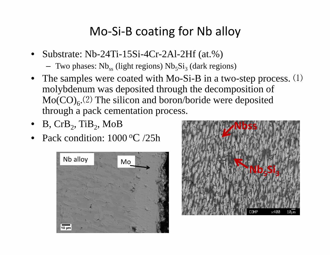
Mo‐Si‐B coating for Nb alloy
• Substrate: Nb-24Ti-15Si-4Cr-2Al-2Hf (at.%)– Two phases: Nbss (light regions) Nb5Si3 (dark regions)
• The samples were coated with Mo-Si-B in a two-step process. ⑴molybdenum was deposited through the decomposition of Mo(CO)6.⑵ The silicon and boron/boride were deposited through a pack cementation process.
• B, CrB2, TiB2, MoB• Pack condition: 1000 oC /25h
Nbss
Nb5Si3MoNb alloy

Si:B 35:1 Si : MoB 10:1
Si : CrB2 20:1 Si : TiB2 10:1
Bsource NbSi2 Boron Zone MoSi2+glass Total (μm)Si:B ~30 ~15 ~30 ~75
MoB ~40 ~10 ~30 ~80CrB2 ~13 ~7 ~30 ~50
TiB2 ~20 0 ~30 ~50
Coating structure (as‐pack) for Nb alloy
• Boride layer reduced with TiB2 and CrB2 substitutions
Nb alloy
Nb alloy
Nb alloy
Nb alloy
MoSi2 MoSi2
MoSi2 MoSi2
NbSi2
NbSi2
NbSi2
NbSi2
(Nb,Ti)+boron
(Nb,Ti)+ boron

Phase B(at.%)
Si(at.%)
Mo(at.%)
Nb(at.%)
Ti(at.%)
Na(at.%)
Al(at.%)
O(at.%)
Hf(at.%)
Cr(at.%)
Elemental total
NbSi2 0 56.94 0.00 25.12 12.56 0.05 0.63 1.41 0.56 2.36 99.63(Nb,Ti)5SiB2
31.88 14.10 0.34 29.90 14.99 0.04 1.22 4.35 0.62 2.54 99.11
MoSi2 0 62.84 29.28 0.01 0.02 0.89 0.63 6.97 0.00 0.10 98.41
EPMA
• XRD of the of sample is composed of MoSi2
• EPMA shows that the boron in the “boride region” is the (Nb,Ti)5SiB2 phase– T2 phase of Nb‐Si‐B system
XRD results of as‐pack sample using CrB2 as B source
Coating structure (as‐pack) for Nb alloy

Bsource: Si ratioWeight gain(mg/cm2)
MoB:Si (1:10) 1.46
CrB2:Si (1:20) 0.81, 0.82
TiB2:Si (1:10) 1.03, 2.37
B:Si (1:20) 1.52
Oxidation: 1300 2 hours in air
MoB TiB2 CrB2
• CrB2 B source shows the lowest mass gain• Surface of sample is composed of borosilica
and MoSi2• NbSi2 converted to Nb5Si3 during oxidation
Oxidation in air 1300 oC /2h CrB2 sample
Si : CrB2 20:1
Nb alloy
Nb5Si3
MoSi2 borosilica
T2

Anneal TGA
• Prior to TGA testing, sample was first annealed in Ar atmosphere at 1200°C for 25 hours, then oxidized in air at 1300°C for 2 hours
– Annealing step allows for NbSi2 to convert to Nb5Si3 for better coating compatibiilty
• TGA testing was conducted on coated Nb alloy (CrB2 B source) at 1300°C for 24 hours
– Mass change: ‐0.83 mg/cm2
– Initial transient stage (volatilization of MoO3) followed by steady state oxidation
– TGA curve shows a coating that prevents catastrophic oxidation of the alloy
Nb alloy Nb5Si3 MoSi2
T2
Phase Crystal Structure CTE in a direction (C‐1) CTE in c direction (if applicable) (C‐1)
MoSi2 Tetragonal I4/mmm (139) 1.04E‐05Mo5Si3 Tetragonal I4/mcm (140) 6.14x10‐6 1.10x10‐5
NbSi2 Hexagonal P62 22 (180) 9.81E‐06 1.13E10‐5Nb5Si3 Tetragonal I4/mcm (140) ~9.0E‐06
Oxidation: 1300 24 hours in air

Zr additions to Mo‐Si‐B coating
• Zr additions were made first by arc melting Mo‐Zr alloys (1, 2at. %Zr)
– Apply Si‐B pack cementation treatment• Static oxidation tests and TGA testing of coated Mo‐Zr alloys
– Samples conditioned at 1500°C for 2 hours prior to testing• Mo‐1at.% Zr 1500°C 50 hours mass change: ‐0.047 mg/cm2
• Zr rich particles seen in cross section and plan view of silica
T2 T1 A15
Element
Line
Atom % Atom %
ErrorO K 45.94 +/‐ 0.43Na K 0.62 +/‐ 0.05Al K 0.56 +/‐ 0.04Si K 33.34 +/‐ 0.13Zr L 19.54 +/‐ 0.09Total 100.00
Mo

TGA Results• TGA Results of Si‐B coated
Mo‐2atZr show reasonable oxidation– Zr additions do not
inhibit the formation of an oxidation resistant coating
• Mass change less than those obtained from Mo‐Si‐B‐Zralloy [ 17] – Oxidation protection not
obtained at temperatures above 1300°C
[17] S. Burk, B. Gorr, V. Trindade, H.‐J. Christ, Oxidation of metals, 73 (2010) 163‐181.
Calculated oxidation rates for MoSiB and MoSiB‐1Zr alloys [13]
‐2.5
‐2
‐1.5
‐1
‐0.5
0
0.5
0 1000 2000 3000 4000 5000
Mass C
hange (m
g/cm
^2)
Time (min)
TGA for Mo‐2at%Zr
1300 C
1200 C
1100 C

SEM: Mo‐2Zr (1500°C, 24 hr)
• Mass change: 1.40 mg/cm2
• Zr‐O phase seen within the substrate (~250 μm from the surface)– Zr additons increasing oxygen diffusion through coating
42 at.% O58 at.% Zr
Mo2Zr

Zr additions to Mo‐Si‐B coating
• Zr additions should be focused within the coating as opposed to the substrate– Could produce unwanted phases compromising the properties of the substrate
• Pack cementation treatment to infuse Zr into the Mo‐Si‐B coating– Check vapor pressures to assess feasibility
• ZrClx much more active compared to ZrFx
500 700 900 1100 1300 1500-40
-35
-30
-25
-20
File: L:\Pack Cementation HSC\GibbsIn_Zr_NaF.OGI
C
Log(Activity)
Temperature
ZrF(g)
ZrF2(g)
ZrF3(g)
ZrF4(g)
500 700 900 1100 1300 1500-35
-30
-25
-20
-15
-10
-5
0
5
File: L:\Pack Cementation HSC\GibbsIn_Zr_NH4Cl.OGI
C
Log(Activity)
Temperature
ZrCl4(g)
ZrCl3(g)
ZrCl2(g)
ZrCl(g)
NaF activator NH4Cl activator

• Si‐B pack cementation applied to polished Mo coins (2mm thickness)– 1000°C 50 hrs
• Samples were ultrasonic cleaned and packed in Zr pack– 5 wt.% Zr– 2.5 wt.% NH4Cl– Bal. Al2O3
– 1000°C 10 hr• Samples oxidized at 1500°C
Zr additions to Mo‐Si‐B coating
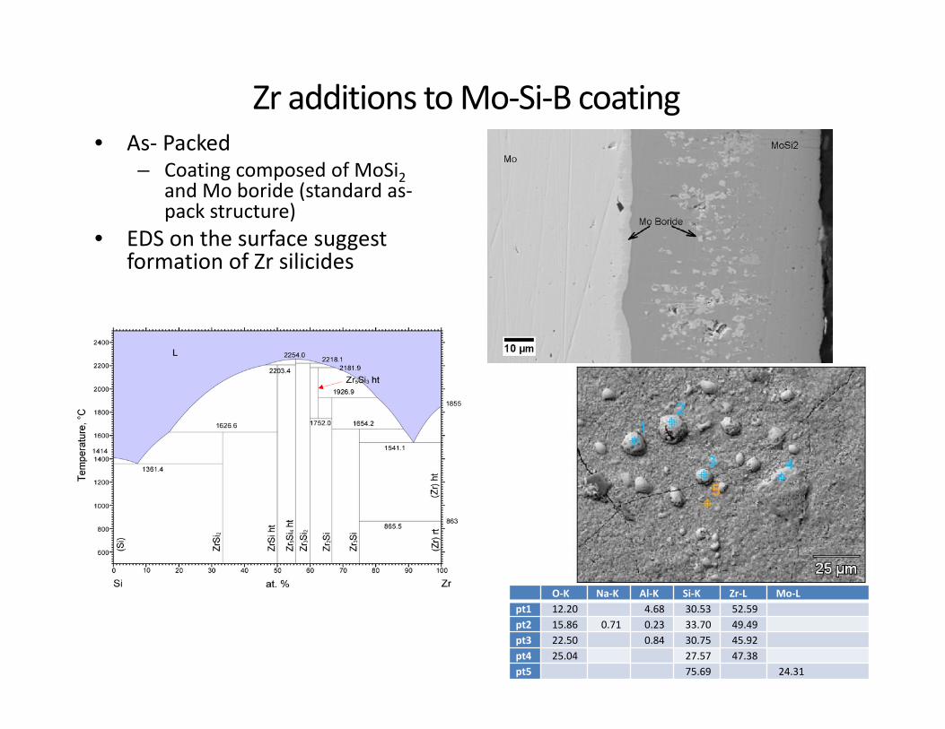
• As‐ Packed– Coating composed of MoSi2
and Mo boride (standard as‐pack structure)
• EDS on the surface suggest formation of Zr silicides
Zr additions to Mo‐Si‐B coating
O‐K Na‐K Al‐K Si‐K Zr‐L Mo‐Lpt1 12.20 4.68 30.53 52.59pt2 15.86 0.71 0.23 33.70 49.49pt3 22.50 0.84 30.75 45.92pt4 25.04 27.57 47.38pt5 75.69 24.31

• Mass change: 0.25 mg/cm2
• Cross section after oxidation shows Mo‐Si‐B coating has converted some of the MoSi2 into T1 and T2
• Surface of sample appears to be completely covered by Zr‐O particles– EDS detects regions containing
both ZrO2 as well as Zircon (ZrSiO4)
Zr additions to Mo‐Si‐B coating: oxidation (1500°C 2hr)
Element
Line
Atom %
O K 62.69Al K 0.37Si K 19.87Si L ‐‐‐Zr L 17.07Zr M ‐‐‐Total 100.00
O‐K Na‐K Al‐K Si‐K Zr‐LBase(209)_pt1 55.56 0.73 0.47 26.77 16.47Base(209)_pt2 54.93 9.42 35.65Base(209)_pt3 56.17 6.98 36.85
250 X

• 1500 C 10 hr, mass change: 1.30 mg/cm2
• XRD shows peaks corresponding to Zircon, MoSi2 and T1
• SEM shows a layer of Zircon formation on top of the borosilica
20.00 25.00 30.00 35.00 40.00 45.00 50.00 55.00 60.00 65.00 70.00 75.00 80.00 85.00 90.00 95.00 100.00
50
100
150
200
250
300
350
400
450
500
550
600
650
700
750
800
850
900
950
1000
0
2theta
Intensity
Cu-Ka1 (1.540600 A)
Experimental pattern: (mosib-zr-5wt-1500c-10hr.raw)[00-041-0612] Mo Si2 Molybdenum Silicide[00-034-0371] Mo5 Si3 Molybdenum Silicide[00-006-0266] Zr Si O4 Zirconium Silicate (Zircon)[00-039-1425] Si O2 Silicon Oxide (Cristobalite, syn)
Element
Line
Atom %
O K 63.40Al K 0.20Si K 18.14Si L ‐‐‐Zr L 18.26Zr M ‐‐‐Total 100.00
Zr additions to Mo‐Si‐B coating: oxidation (1500°C 10hr)

Future Work: Utilize plasma spray deposition• Thermal spray process combined with
Si‐B pack cementation technique is an effective process to produce Mo‐Si‐B coatings on larger samples [18]– Plasma spray deposition of Mo
allows for samples to be scaled up in size and complexity
• Formation of a larger coating allowing for more aggressive oxidation testing for Nb and Nballoys Substrate
Mo layer
Si‐B layer
[18] P. Ritt, O. Lu‐Steffes, R. Sakidja, J. H. Perepezko, W. Lenling, D. Crawmer, J. Beske. “Application of Plasma Spraying as a Precursor in the Synthesis of Oxidation Resistant Coatings.” Journal of Thermal Spray Technology. (2013)

Future Work: Formation of Smart Coating• Optimization of parameters for the CVD
coating processes• Integration of the smart coating into an
expanded range of other TM‐based alloys with emphasis on Nb‐based alloys.
• Coatings with a compositional gradient decrease residual stresses [19]
– Sharp changes in stresses may result in delamination of the coating
• Object Oriented FEA (OOF2) is public domain finite element analysis (FEA) software created by NIST to investigate the properties of microstructures
– utilizes actual microstructure images as the basis for the finite element mesh
– Obtain a coating structure that minimizes the residual stresses due to CTE mismatch of the coating and substrate
Temperatures of the TBC, BC, and Nb‐Silicide as Measured during the JETS Test; the BC Temperature Was Calculated Using Measurements of the Temperatures of the TBC and Nb‐Silicide Substrate, Together with Thermal Conductivity Measurements [20]
[20] Bewlay, B. P., Jackson, M. R., Subramanian, P. R., & Zhao, J. C. (2003). A review of very‐high‐temperature Nb‐silicide‐based composites.Metallurgical and Materials Transactions A, 34(10), 2043‐2052.
[19] X.C. Zhang, B.S. X u, H.D. Wang, Y. Jiang, Y.X. Wu, Thin Solid Films, 497 (2006) 223‐231

OOF‐2: Boundary Conditions• Bottom
– Y=0 (substrate)– X free to move (infinite plane)
• Left side– X=0 – Y free to move (no constraints on
top of coating)• Right side
– X= allow for free expansion such that ∑ 0
– Want non‐free surfaces to expand in a planar fashion
• Run simulation first under no constraints to provide estimate of expansion taking place

OOF‐2: Materials and BC
• Isotropic values• Assume at 1000°C the
coating is in a relaxed state (temperature at which coating forms).
• Boundary Conditions– Thot= 300– Tcold = 0– Ybottom =0– Xleft =0– Xright = 2.23x10‐8 m
MaterialDensity (kg/m^3)
Young's Modulus (GPa)
Poisson Ratio
Thermal Cond (W/mK) CTE (C‐1)
Mo 10200 324.8 0.293 138 6.50x10‐6
MoSi2 6300 432 0.151 28.6 1.04x10‐5
Mo5Si3 (T1) 8190 363 .268 19 8.35x10‐6
Mo5SiB2 (T2) 8800 383 0.27 28 8.5x10‐6
borosilicate glass 2400 64 0.19 1.1 4.00x10‐6
138.35 microns
98.28 microns
Thot
Tcold FEM mesh generated in OOF‐2

OOF‐2: Stesses• Top portion of coating is in compression while bottom (substrate) is in tension
• Compressive yield stress for MoSi2: 769 MPa– Suggests that coating will be intact under these conditions
87 MPa
‐127 MPa
‐150
‐100
‐50
0
50
100
SiO2 MoSi2 T1 T2 Mo
Stress (M
Pa)
Phase
Range of Stresses in Phases of the Coating

Concluding Remarks
• Mo‐Si‐B coating applied to Nb alloys to provide oxidation resistance– Can be synthesized first by applying a Mo layer via decomposition of
molybdenum hexacarbonyl followed by a Si‐B co‐pack cementation process
– Boride formation during pack cementation process within Nb produces undesirable coating structure, but can be optimize using different boride source
– Enhanced oxidation protection by reducing the formation of Nb oxides in favor for a protective borosilica coating
• Coated Mo‐Zr alloys show promise that the transition metal oxide can develop within the Mo‐Si‐B coating to provide further environmental protection. – Zr can be added to Mo‐Si‐B coating via pack cementation technique
• Upon oxidation, oxidation resistant silica and zircon/zirconia form– Coating provides the necessary components for the development of a
smart coating for refractory metal alloys.

Thank You!

List of papers published, conference presentations, students supported under grant FE0007377
• Publications: – Lu‐Steffes, O. J., Sakidja, R., Bero, J. & Perepezko, J. H. Multicomponent coating for enhanced
oxidation resistance of tungsten. Surface and Coatings Technology 207, 614‐619, doi:10.1016/j.surfcoat.2012.08.011 (2012)
– P. Ritt, O. Lu‐Steffes, R. Sakidja, J. H. Perepezko, W. Lenling, D. Crawmer, J. Beske. “Application of Plasma Spraying as a Precursor in the Synthesis of Oxidation Resistant Coatings.” Journal of Thermal Spray Technology. doi:10.1007/s11666‐013‐9947‐2 (2013)
– C. C. Dharmawardhana, R. Sakidja, S. Aryal, and W. Y. Ching, “Temperature dependent mechanical properties of Mo‐‐Si‐‐B compounds via ab initio molecular dynamics ,” APL Mater. 1, 012106 (2013), DOI:10.1063/1.4809539
• Conferences– Research results were presented at the 2012 Materials Science and Technology conference in the
symposium “Beyond Nickel Based Superalloys‐II.” The title of the presentation was “Transition Metal Doped Mo‐Si‐B Coatings.”
– Research results were presented at the 2012 First ACEEES International Forum. The title of the presentation was “Design and Synthesis of Zr Doped Mo‐Si‐B Coatings”
– Research results were presented at the 2013 Materials Science and Technology conference in the symposium “High Temperature Corrosion and Oxidation of Materials.” The title of the presentation is “Mo‐Si‐B Coatings on Niobium Base Systems for Enhanced Oxidation Protection”
– Research results were presented at the 2013 Second ACEEES International Forum. The title of the presentation was “Enhanced Oxidation Protection for Niobium Base Alloys Utilizing a Mo‐Si‐B Coating”
– Research Accomplishments from this project were presented at the 2012 University Coal Research/Historically Black Colleges and Universities and Other Minority Institutions Contractors Review that took place on May 31, 2012.
– Research Accomplishments from this project were presented at the 2013 University Coal Research/Historically Black Colleges and Universities and Other Minority Institutions Contractors Review that took place on June 11‐13, 2013.
• Support– John Perepezko; PI– Otto Lu‐Steffes; graduate student– Dana Jackson; undergraduate laboratory assistant